WJ Communications SX1115 User Manual 6030cn
WJ Communications, Inc. 6030cn
Contents
- 1. Excerpt from Cisco manual showing antenna mounting
- 2. Suhner antenna data
- 3. Hardware manual will be same for UNII but with MPE values shown in WJ test repor
- 4. RadioWave antenna data, page 1
- 5. RadioWave antenna, page 2
- 6. RadioWave antena, page 3
- 7. RSI Comsat patch antenna data, page 1
- 8. RSI patch, page 2
- 9. RSI patch, page 3
- 10. RSI patch, page 4
- 11. Antnenna mount detail, RadioWave 4 ft dish
- 12. Antennas used during tests (antenna list)
- 13. 14 dBi corne antenna data sheet
- 14. Response to 2 Dec request re MPE
- 15. WJ instruction manual with page 7 to be replaced
- 16. Mobil Mark antenna info
- 17. Radio Wave antenna info
- 18. Includes multiple antenna location instructions to installer
- 19. pdf version of MPE info from WJ
- 20. Copy of email sent to you and Kwok re MPE
- 21. Revised antenna installation instruction
Excerpt from Cisco manual showing antenna mounting
28 Cisco uBR7200 Series Universal Broadband Router Wireless Modem Card and Subsystem Installation and Configuration
Installing a Wireless Transverter
Final Review - Cisco Internal Use Only
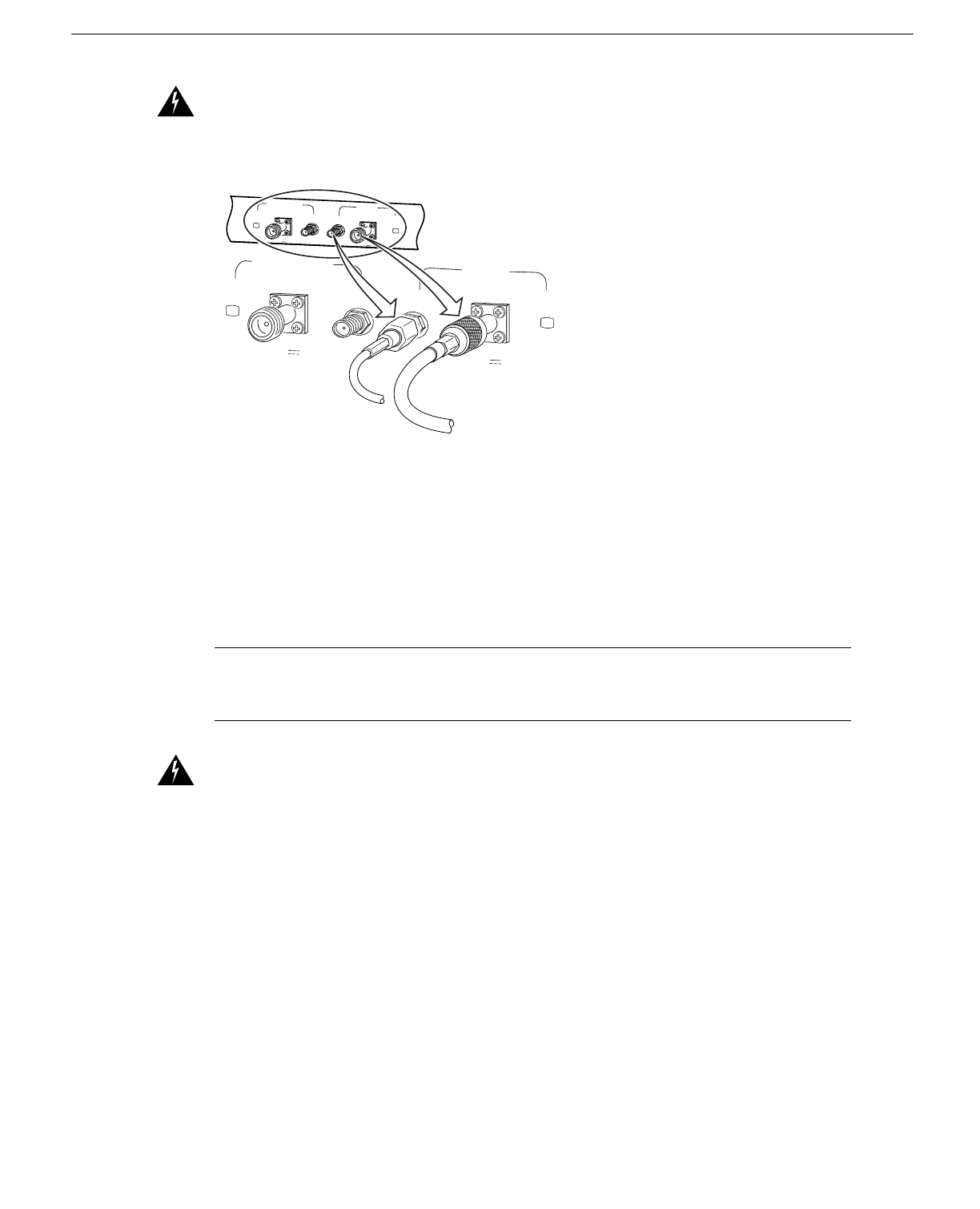
Warning Use RG-214 or similar size 50-ohm coaxial cable with a center conductor size of 14 AWG
or larger. Failure to do so can result in overheating and long-term failure.
Figure 29 Connecting the IF Cable (to the Wireless Transverter)
If you will be using the diversity feature, attach a second cable to the Diversity-ODU/Output
connector.
This completes the procedure for installing and cabling a power feed panel.
Installing a Wireless Transverter
This section provides instructions for installing the duplexer assembly in the transverter chassis, then
installing the transverter on the antenna mast.
Note These instructions apply to the MMDS transverter manufactured and supplied by Cisco. If
you have purchased a transverter from another vendor, refer to that vendor’s instructions for
installation.
Warning Do not locate the transverter near overhead power lines or other electric light or power
circuits, or where it can come into contact with such circuits. (See Figure 30.) When installing the
transverter, take extreme care not to come into contact with such circuits, as they may cause serious
injury and death.
OUTPUT
-48V ,7A OUTPUT
-48V ,7A
28542
PWR
ON PWR
ON
DIVERSITY
ODU ODU
MC MC
MAIN
PWR
ON PWR
ON
DIVERSITY
ODU ODU
MC MC
MAIN
OUTPUT
-48V ,7A OUTPUT
-48V ,7A
Cisco uBR7200 Series Universal Broadband Router Wireless Modem Card and Subsystem Installation and Configuration 29
Installing a Wireless Transverter
Final Review - Cisco Internal Use Only
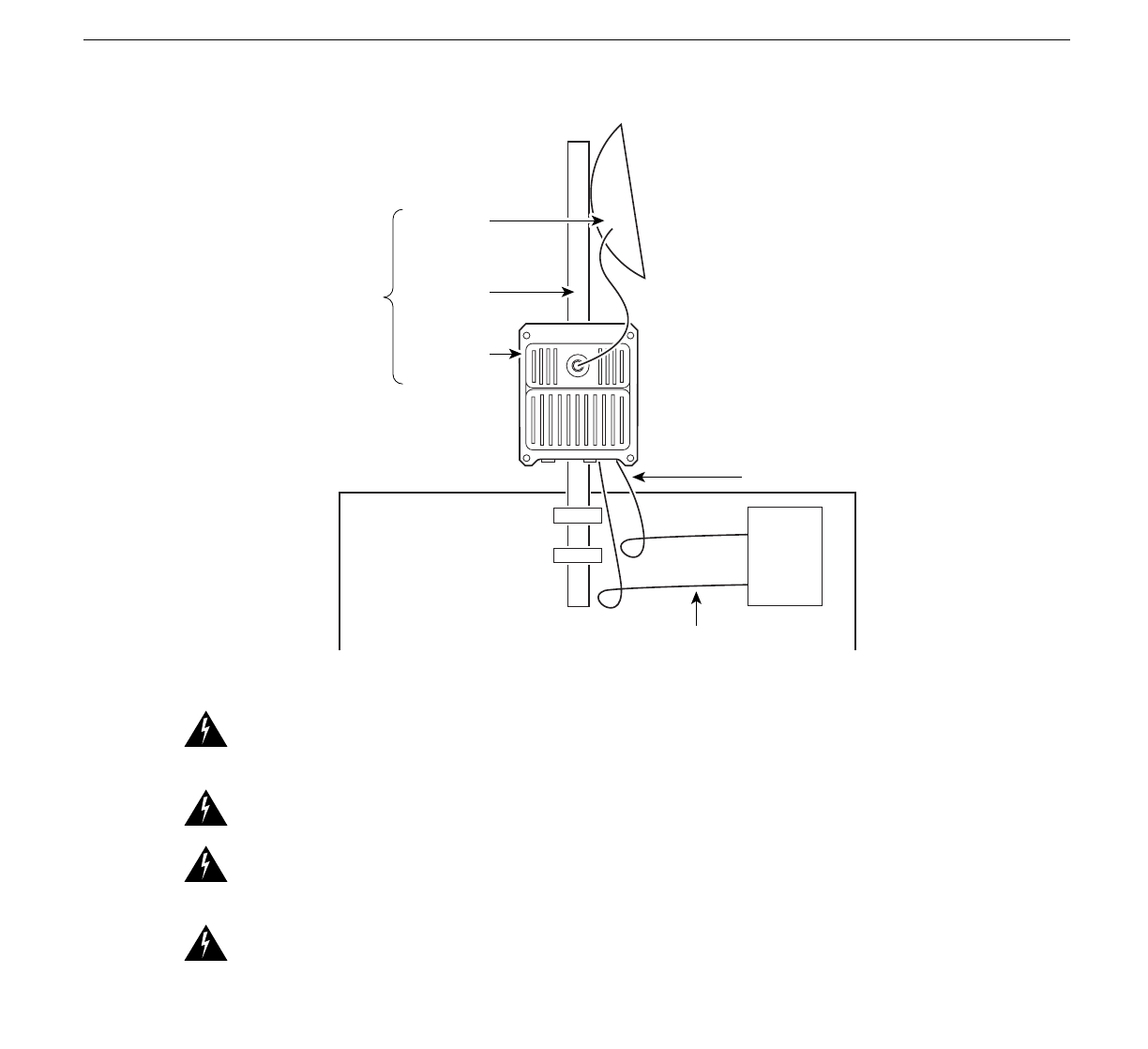
Figure 30 Roof Installation Considerations
Warning This unit is intended for installation in restricted access areas. A restricted access area is
where access can only be gained by service personnel through the use of a special tool, lock and key,
or other means of security, and is controlled by the authority responsible for the location.
Warning When installing the unit, the ground connection must always be made first and
disconnected last.
Warning Never defeat the ground conductor or operate the equipment in the absence of a suitably
installed ground conductor. Contact the appropriate electrical inspection authority or an electrician
if you are uncertain that suitable grounding is available.
Warning A radiation hazard may exist within a specific radius around the center point of the
antenna. The table below associates antenna gain (in dB) with a minimum acceptable distance.
Determine the gain of the antenna and use Table 6 to locate the minimum acceptable distance from
the center point of the antenna. (Transmitter Power = 33 dBi.)
Table 6 Radiation Hazard Calculation
Antenna
Gain
(dBi) EIRP
(dBm) EIRP
(W)
Minimum Acceptable
Distance under FCC Rules
– Uncontrolled
Environment (m)
Minimum Acceptable
Distance under FCC Rules
– Controlled Environment
(m)
10 43 20.0 0.4 </= 20 cm
11 44 25.1 0.4 </= 20 cm
12 45 31.6 0.5 </= 20 cm
13 46 39.8 0.6 0.3
27290
Wireless
Transverter
Mast
NEC Article 810
CEC Section 54
IF Power Cable
NEC Article 820
CEC Section 54
Control Cable
NEC Article 800
CEC Article 60
Antenna