Walker Mc 16 Hp Users Manual Parts 12012000
!! Walker-24 Walker Lawn Mower Manuals - Lawn Mower Manuals – The Best Lawn Mower Manuals Collection
MC (16 HP) to the manual a2e4376f-fa81-40da-9f76-66500564e6c0
2015-02-03
: Walker Walker-Mc-16-Hp-Users-Manual-476323 walker-mc-16-hp-users-manual-476323 walker pdf
Open the PDF directly: View PDF ![]() .
.
Page Count: 64

ILLUSTRATED
PARTS MANUAL
Model MC (16 HP)
(Covers Serial Numbers 01-49733 and on)
Effective Date: P/N 6000-6
12-01-00 Price $5.00
TM

Use only genuine Walker® replacement parts. Effective Date 12-01-00
KEY TO ABBREVIATIONS USED IN THIS MANUAL
º (Dimension) .................................................................................................................................... Degrees (Angle)
" (Dimension) .................................................................................................................................................... inches
(-) ...................................................................................................................................................Negative (Polarity)
(+).................................................................................................................................................... Positive (Polarity)
AT................................................................................................................................................................ All-Terrain
CCW .............................................................................................................................................. Counter-clockwise
Conn. ..........................................................................................................................................................Connector
CW .............................................................................................................................................................. Clockwise
D ...................................................................................................................................................................Diameter
DGHS...................................................................... Deck, Grass Handling System (number refers to size in inches)
DML ............................................................................................... Deck, Mulching (number refers to size in inches)
DSD ..................................................................................... Deck, Side Discharge (number refers to size in inches)
DU................................................................................................................................................... Garlock (Bearing)
ESNA (Fastener).........................................................................................................................Nylon Insert Locknut
FSC........................................................................................................................................ Forward Speed Control
GA.....................................................................................................................................................................Gauge
gal. .....................................................................................................................................................................gallon
GHS .......................................................................................................................................Grass Handling System
GR (Fastener) ................................................................................................................................................... Grade
HP ...........................................................................................................................................................Horse Power
HT .......................................................................................................................................................... Heat-Treated
ID ..............................................................................................................................Identification or Inside Diameter
L ....................................................................................................................................................................... Length
LH ..........................................................................................................Left Hand (orientated with operator on seat)
LP...............................................................................................................................................................Low Profile
mm (Dimension)......................................................................................................................................... millimeters
MS (Fastener) .....................................................................................................................................Machine Screw
NS (as part number) ...................................................................................Item is not sold by Walker Manufacturing
OD................................................................................................................................................... Outside Diameter
oz. ......................................................................................................................................................................ounce
PFH (Fastener) ............................................................................................................................... Phillips Flat Head
P/N .......................................................................................................................................................... Part Number
PPH (Fastener) ............................................................................................................................... Phillips Pan Head
PTH (Fastener) .............................................................................................................................Phillips Truss Head
PTO.....................................................................................................................................................Power Take-Off
QKS .......................................................................................................................................................... Quick Slide
qt. ........................................................................................................................................................................ quart
RH....................................................................................................... Right Hand (orientated with operator on seat)
SAE (Fastener) ....................................................................................................... Society of Automotive Engineers
SBH (Fastener) ..................................................................................................................Socket Button Head (Bolt)
SD .......................................................................................................................................................Side Discharge
SFH (Fastener) ................................................................................................................................Slotted Flat Head
SHC (Fastener) ............................................................................................................................... Socket Head Cap
SHL (Fastener) ................................................................................................................................... Shoulder (Bolt)
SM (Fastener) .............................................................................................................................Sheet Metal (Screw)
S/N ....................................................................................................................................................... Serial Number
Spg.................................................................................................................................................................... Spring
SQH (Fastener)...................................................................................................................................... Square Head
SS (Fastener).......................................................................................................................................Stainless Steel
ST (Fastener)............................................................................................................................. Self-Tapping (Screw)
Term. ..............................................................................................................................................................Terminal
V...........................................................................................................................................................................Volts
NOTE: In some instances, combinations of abbreviations may be used (e.g. PPHMS - Phillips Pan Head Machine Screw).
Abbreviation What it Represents

1
Effective Date 12-01-00 Use only genuine Walker® replacement parts.
Decals
Tractor Decals.......................................................... 2
Body / Chassis Assemblies
Body / Chassis Assembly (GHS Models)................. 4
Body Assembly
(GHS 9.5 Bushel Models).................................. 6
(SD Models)....................................................... 8
Tractor Components
Main Component Power Transmission
(GHS Models).................................................. 10
(SD Models)..................................................... 12
Engine Group......................................................... 14
Hydrostatic Ground Drive Assemblies ................... 16
Steering Control Assemblies.................................. 18
Throttle & Choke Control Assemblies .................... 20
Parking Brake Assembly ........................................ 22
GHS Group ............................................................ 24
GHS Powerfil® Assembly....................................... 26
GHS 6.7 Bushel Catcher &
Exhaust Deflector Assemblies ............................... 28
GHS 9.5 Bushel Catcher &
Exhaust Deflector Assemblies ............................... 30
Electrical Components
Electrical Assemblies
(Chassis Components) .................................... 32
(Body Components)......................................... 34
(GHS 6.7 Bushel Components) ....................... 36
(GHS 9.5 Bushel Components) ....................... 38
Electrical Connectors....................................... 40
Options and Kits
Armrest Kit / Touch-Up Paint ................................. 42
Comfort Seat / Armrest Kit ..................................... 44
Suspension Seat Kit............................................... 46
Light Kit .................................................................. 48
Case-Hardened Blower Kit .................................... 50
No Catch Deflector Kit (6.7 Bushel) ....................... 52
No Catch Deflector Kit (9.5 Bushel) ....................... 54
All-Terrain Tire Kit & Tire Chain Sets..................... 56
Maintenance
Lubrication Points .................................................. 58
Wiring Schematic ................................................... 60
Warranty
Limited Warranty .................................................... 61
Section of Mower Covered Page Section of Mower Covered Page
ILLUSTRATED PARTS LIST

2
IT E M P A R T DE S C R IP T I O N LO C ATI O N N O . NO .
NO. NO. REQ’D. GHS REQ’D SD
Use only genuine Walker® replacement parts. Effective Date 12-01-00
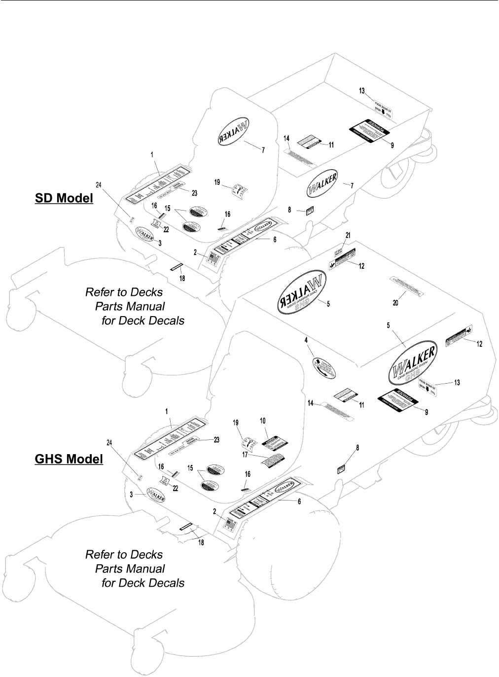
TRACTOR DECALS
Walker Product and Operation Decals
1 7802 RH Fender Body, RH near Seat 1 1
2 5856 Made in USA Body, Spring Bracket 1 1
3 5803 Walker Manufacturing Logo Body 1 1
4 5813-1 Powerfil®6.7 / 9.5 Bushel Catcher, Front 1 0
5 5801 GHS 6.7 / 9.5 Bushel Catcher (one on each side) 2 0
6 5802-2 LH Fender Body, LH near Seat 1 1
7 5800 Walker Mower (4 x 7-1/2) Utility Bed (one on each side) 0 2
Danger Decals Warning Decals Caution Decals
8 5805 Caution, Engine Exhaust Body, LH Side 1 1
9 5861 Danger, Raised Body Body - Underside, Center 1 1
10 5804 Danger, Rotating Blower Blades Body near Body Chute 1 0
11 6810 Danger, Engine Exhaust Engine 1 1
12 5868 Danger, Pinch Point 6.7 / 9.5 Bushel Catcher Mounting Frame Assembly 2 0
(one on each side)
Maintenance Decals
13 5815 Body Lift Rear Bumper 1 1
14 5855 Important, Engine Cooling Engine 1 1
15 5810-2 Reservoir Hydrostatic Drives (one on each) 2 2
16 5810-1 Axle Oil Level Gear Axle Drive Assemblies (one on each) 2 2
17 5819 Blower Maintenance Blower Housing 1 0
18 6875 PTO Alignment Arrow Universal Joint Tube Assembly 1 1
19 7827 Oil Level Jackshaft Support 1 1
20 5869 Removable Screen 6.7 / 9.5 Bushel Catcher Removable Screen 1 0
21 5874 Push to Release 6.7 / 9.5 Bushel Catcher Safety Latch 1 0
22 6807 Oil Pressure Body 1 1
23 7809 Parking Brake Body, RH below seat 1 1
Option Decals (applied only to units with corresponding Options installed)
24 5877 Lights, On-Off Body 1 1
8500-8 No Catch Deflector 6.7 / 9.5 Bushel No Catch Deflector, LH Side 1 0
(Refer to 6.7 or 9.5 Bushel No Catch Deflector Kit Listing)
8500-9 No Catch Deflector, Off-On Body, RH above fender 1 0
(Refer to 6.7 Bushel No Catch Deflector Kit Listing)
NOTE: All parts requiring decals are shipped with decals applied.
3
Effective Date 12-01-00 Use only genuine Walker® replacement parts.
TRACTOR DECALS

4
ITEM PART DESCRIP TION NO.
NO. NO. REQ’D ITEM PART DESCRIP TION NO.
NO. NO. REQ’D
Use only genuine Walker® replacement parts. Effective Date 12-01-00
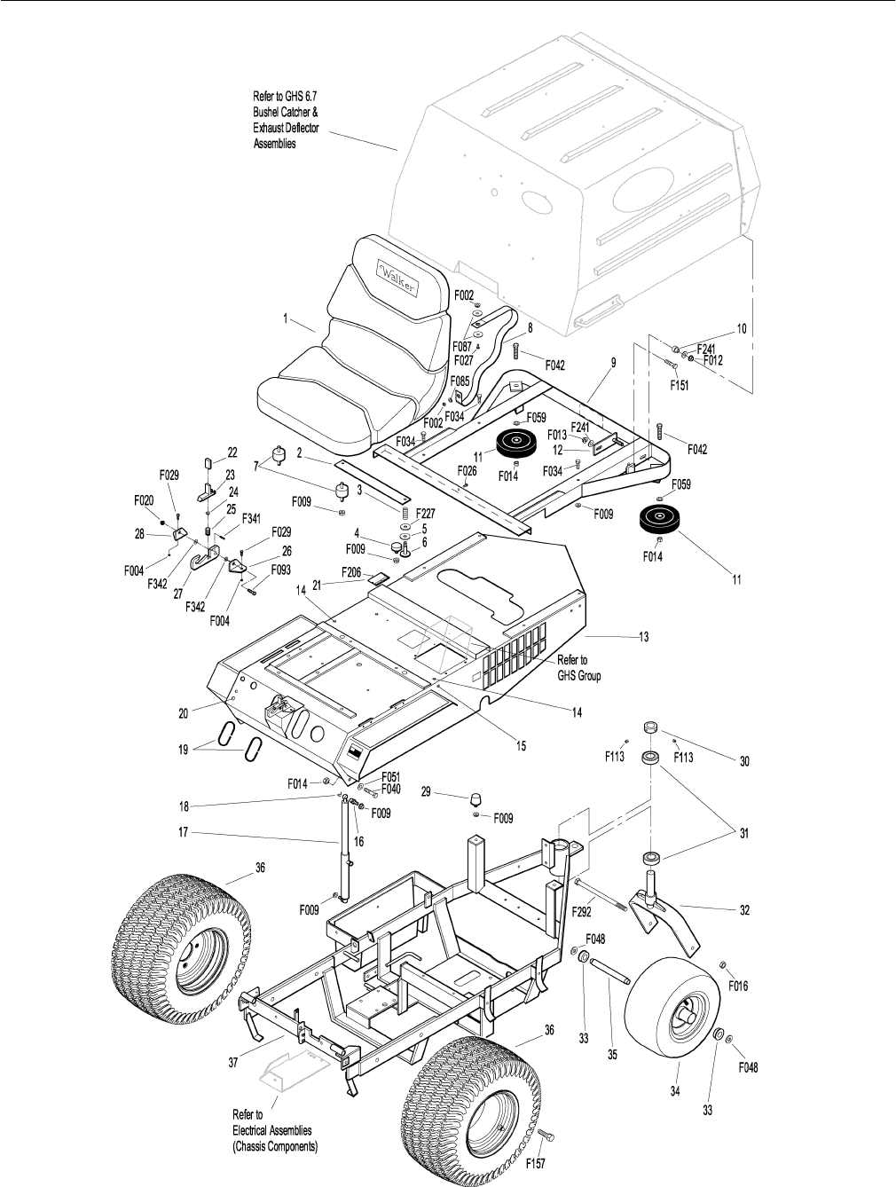
BODY / CHASSIS ASSEMBLY (GHS MODELS)
Seat Assembly
1 5103 Seat 1
2 7203 Seat Spring Plate 1
3 7223 Compression Spring (1/2 x 1) 2
4 7845 Rubber Bumper (1.375 OD x .63) 2
5 7846 Rubber Washer (3/8 ID x 1-1/4 OD x 1/8) 2
6 7204 Shoulder Bolt, Seat Mount 2
7 7440-5 Shock Mount (1.25 D x .75) 2
Rear Bumper Assembly (GHS 6.7 Bushel Models Only)*
8 5566 Tilt Stop Strap 1
9 5516 Rear Bumper (6.7) 1
10 7516-5 Catcher Pivot Bushing 2
11 5162 Roller Wheel (5") 2
12 7517-2 Catcher Pivot Plate 2
Body Assembly
13 6100-7 Welded Body 1
14 5989-3 Dome Plug (5/16) 2
15 5989-4 Dome Plug (3/8) 2
16 7146 13mm Ball Stud 2
17 5145 Gas Spring Assembly 1
(Includes Items # 16 & 18)
18 7147 Spring Clip 2
19 5180 Edge Molding, Lever Opening 2
20 5989-5 Dome Plug (7/16) 1
21 NS Body ID Plate 1
Tilt-Up Latch Assembly
22 5847 Plastic Tip 1
23 5744-20 Tilt-Up Latch Spring Arm 1
24 5744-10 Spring Pivot Bushing 1
25 5744-15 Compression Spring (3/8 x 5/8) 1
26 5744-13 Mount Angle, LH 1
27 5744-12 Hook, Tilt-Up Latch 1
28 5744-14 Mount Angle, RH 1
Chassis Assembly
29 5845 Rubber Bumper (1.50 OD x 1.25) 2
30 5267-1 Retainer Collar (1") 1
(Includes Item # F113)
31 5270-1 Pivot Bearing 2
32 5420-2 Tail Wheel Fork 1
33 5037-1 Bearing 2
34 5035 Tail Wheel & Tire Assembly (13 x 6.50-6) 1
5035-1 Tire Only (13 x 6.50-6) **
5036 Wheel & Hub Only (6 x 4.5) **
35 5038-1 Axle Spacer Tube (6-5/8) 1
36 5075 Wheel & Tire Assembly LP (18 x 8.50-10) 2
5070-2 Tire Only (18 x 8.50-8) **
5070-4 Wheel Only (8 x 7) **
5033-2 Wheel & Tire Assembly (18 x 6.50-8) ***
5030-2 Tire Only (18 x 6.50-8) **
5031-2 Wheel Only (8 x 5.5) **
5030-4 Tire Tube (18 x 8.50-8) **
37 6307-1 Chassis Frame 1
Fasteners
F002 10-24 Keps Nut 2
F004 1/4-20 Keps Nut 2
F009 5/16-18 Whiz Locknut 10
F012 3/8-16 Keps Nut 2
F013 3/8-16 Whiz Locknut 2
F014 3/8-16 ESNA Nut 4
F016 1/2-13 Self-Locking Nut 1
F020 5/16-18 ESNA Nut 1
F026 10-24 x 1/2 PPHMS 1
F027 10-24 x 5/8 PPHMS 1
F029 1/4-20 x 1/2 Hex Bolt 2
F034 5/16-18 x 3/4 Hex Bolt 4
F040 3/8-16 x 1-1/2 Hex Bolt 2
F042 3/8-16 x 2 1/4 Hex Bolt 2
F048 1/2 SAE Washer 2
F051 3/8 SAE Washer 2
F059 3/8 Wave Spring Washer 2
F085 3/16 Rivet Backup Washer 1
F087 #10 x 7/8 Fender Washer 2
F093 5/16-18 x 1 Hex Bolt 1
F113 5/16-18 x 5/16 Set Screw 2
F151 3/8-16 x 7/8 Hex Bolt 2
F157 1/2-20 x 1-1/4 Wheel Lug Bolt 8
F206 #2 x 3/16 Drive Pin 2
F227 3/8 x 1-1/4 x 1/8 Plastic Washer 2
F241 .375 x .875 x .10 Washer 4
F292 1/2-13 x 8-1/2 Hex Bolt GR 2 1
F341 Coil Roll Pin (7/64 x 9/16) 1
F342 5/16 Conical Washer 2
*Rear Bumper Assembly for GHS 9.5 Bushel Models is not
shown here. Refer to BODY ASSEMBLY (GHS 9.5 BUSHEL
MODELS), Page 6. Rear Bumper Assembly for SD Models is
not shown here. Refer to BODY ASSEMBLY (SD MODELS),
Page 8.
** Service Part Only
*** May be ordered as a factory-installed option or for dealer
installation. Narrow Drive Tires are used when installing a 36"
Deck. Contact your Walker dealer.
5
Effective Date 12-01-00 Use only genuine Walker® replacement parts.
BODY / CHASSIS ASSEMBLY (GHS MODELS)

6
ITEM PART DESCRIP TION NO.
NO. NO. REQ’D ITEM PART DESCRIP TION NO.
NO. NO. REQ’D
Use only genuine Walker® replacement parts. Effective Date 12-01-00
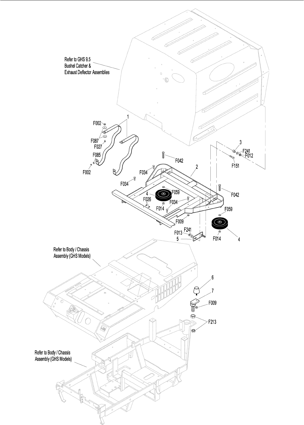
BODY ASSEMBLY (GHS 9.5 BUSHEL MODELS)
Body Assembly (GHS 9.5 Bushel Models Only)*
1 5566 Tilt Stop Strap 2
2 5516-15 Rear Bumper (9.5) MC Twin 1
3 7516-5 Catcher Pivot Bushing 2
4 5162 Roller Wheel (5") 2
5 7517-2 Catcher Pivot Plate 2
6 5845 Rubber Bumper (1.50 OD x 1.25) 1
7 5516-10 Bumper Mount (C-Twin) 2
Fasteners
F002 10-24 Keps Nut 4
F009 5/16-18 Whiz Locknut 5
F012 3/8-16 Keps Nut 2
F013 3/8-16 Whiz Locknut 2
F014 3/8-16 ESNA Nut 2
F026 10-24 x 1/2 PPHMS 2
F027 10-24 x 5/8 PPHMS 2
F034 5/16-18 x 3/4 Hex Bolt 4
F042 3/8-16 x 2-1/4 Hex Bolt 2
F059 3/8 Wave Spring Washer 2
F085 3/16 Rivet Backup Washer 2
F087 #10 x 7/8 Fender Washer 4
F151 3/8-16 x 7/8 Hex Bolt 2
F213 3/4-10 Jam Nut 2
F241 .375 x .875 x .10 Washer 4
*Rear Bumper Assembly for GHS 6.7 Bushel Models is not
shown here. Refer to BODY / CHASSIS ASSEMBLY (GHS
MODELS), Page 4. Rear Bumper Assembly for SD Models is
not shown here. Refer to BODY ASSEMBLY (SD MODELS),
Page 8.
NOTE: Refer to BODY / CHASSIS ASSEMBLY (GHS MODELS),
Page 4 for all common parts used on both GHS and SD
models.
7
Effective Date 12-01-00 Use only genuine Walker® replacement parts.
BODY ASSEMBLY (GHS 9.5 BUSHEL MODELS)

8
ITEM PART DESCRIP TION NO.
NO. NO. REQ’D ITEM PART DESCRIP TION NO.
NO. NO. REQ’D
Use only genuine Walker® replacement parts. Effective Date 12-01-00
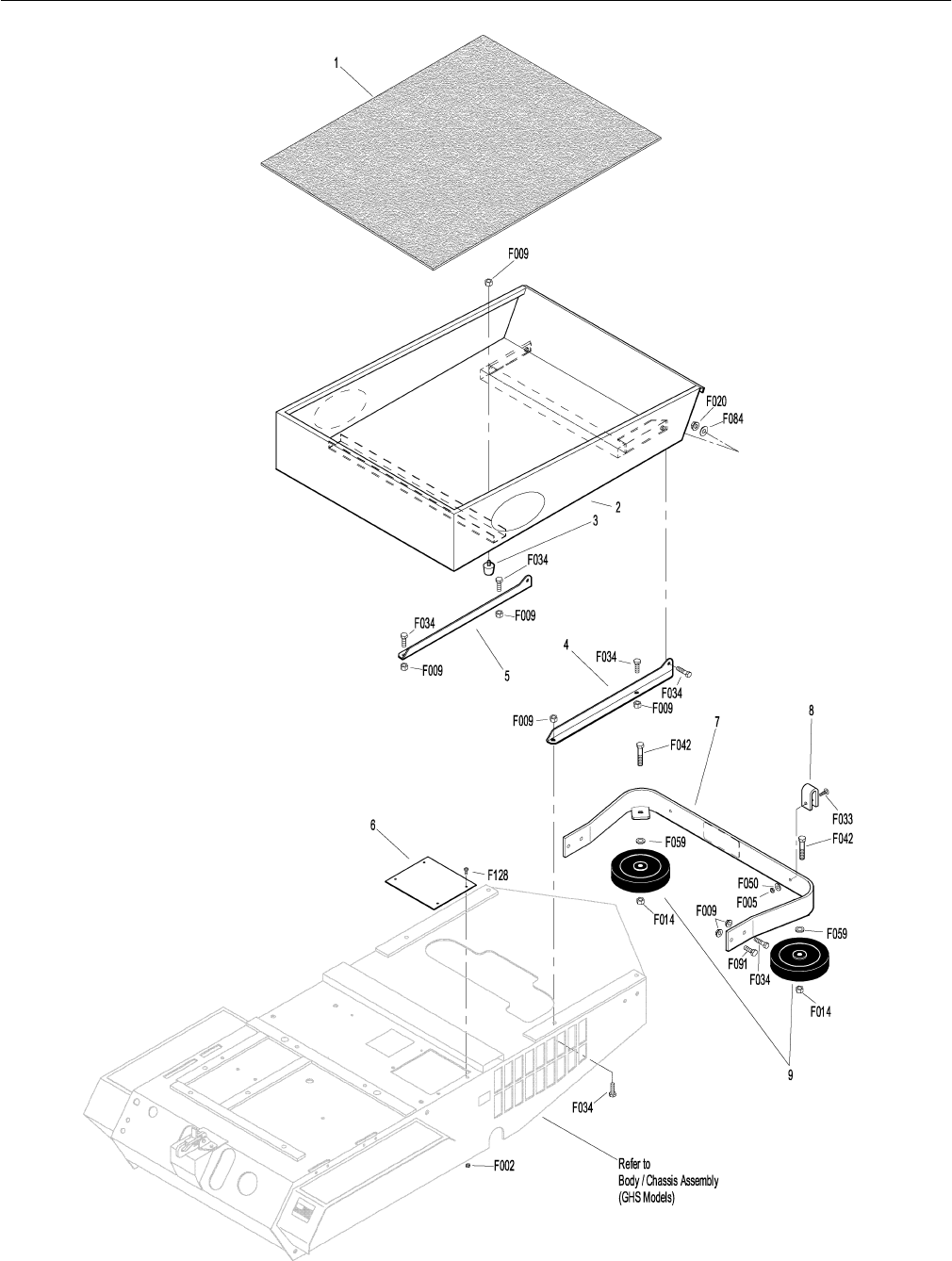
BODY ASSEMBLY (SD MODELS)
Utility Bed Assembly
1 8650-10 Bed Liner 1
2 5656 Utility Bed 1
(Includes Items # 1 & 3)
3 5845 Rubber Bumper (1.50 OD x 1.25) 2
4 5652-1 Utility Bed Mount, LH 1
5 5651-1 Utility Bed Mount, RH 1
Rear Bumper Assembly (SD Models Only)*
6 7153-3 Cover Plate 1
7 5112 Rear Bumper 1
8 5161 Bumper Pad 2
9 5162 Roller Wheel (5") 2
Fasteners
F002 10-24 Keps Nut 4
F005 1/4-20 ESNA Nut 2
F009 5/16-18 Whiz Locknut 10
F014 3/8-16 ESNA Nut 2
F020 5/16-18 ESNA Nut 2
F033 1/4-20 x 1 PTH Bolt 2
F034 5/16-18 x 3/4 Hex Bolt 8
F042 3/8-16 x 2-1/4 Hex Bolt 2
F050 1/4 SAE Washer 2
F059 3/8 Wave Spring Washer 2
F084 5/16 Wave Spring Washer 2
F091 5/16-18 x 5/8 Hex Bolt 2
F128 10-24 x 3/8 PTHMS 4
*Rear Bumper Assembly for GHS Models is not shown here.
Refer to BODY / CHASSIS ASSEMBLY (GHS MODELS),
Page 4, or BODY ASSEMBLY (GHS 9.5 BUSHEL MOD-
ELS), Page 6.
NOTE: Refer to BODY / CHASSIS ASSEMBLY (GHS MODELS),
Page 4 for all common parts used on both GHS and SD
models.
9
Effective Date 12-01-00 Use only genuine Walker® replacement parts.
BODY ASSEMBLY (SD MODELS)

10
ITEM PART DESCRIP TION NO.
NO. NO. REQ’D ITEM PART DESCRIP TION NO.
NO. NO. REQ’D
Use only genuine Walker® replacement parts. Effective Date 12-01-00
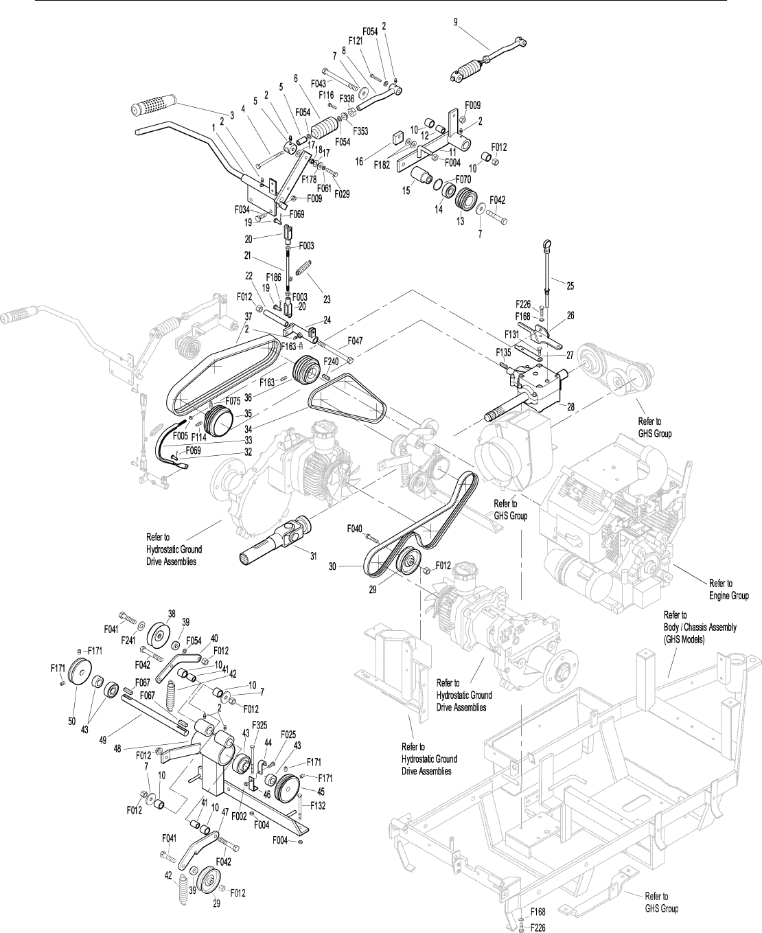
MAIN COMPONENT POWER TRANSMISSION (GHS MODELS)
Clutch Lever Assembly
1 6358-1 Clutch Lever (Includes Items # 2 & 3) 1
2 5830 Grease Fitting 6
3 7860 Handle Grip 1
4 7303-10 Clutch Actuator Bolt (3/8) 1
5 7380-5 Knuckle Joint, 3/8 ID 1
6 7226-10 Compression Spring (3/4 x 2-1/2) 1
7 5841 Retainer Washer 4
8 6130-5 Push Rod, Clutch Actuator 1
9 6130-10 Clutch Actuator Rod Assembly 1
(Includes Items # 2, 4-6, 8,
F054, F336 & F353)
10 7201-3 DU Bearing 6
11 8368 PTO Belt Tightener 1
12 7201-5 Inner Race (2-1/4) 1
13 8243-1 Clutch Idler Pulley 1
8243 Clutch Idler Pulley Assembly 1
(Includes Items # 14, 15 & F070)
14 5265 Bearing (3/4) 1
15 8243-3 Hub, Idler Pulley 1
16 8375 PTO Belt Tightener Stop 1
17 7377 Plastic Washer (1 x .438 x .025) 2
18 7378 Pivot Bearing (7/16 x 9/16) 1
19 5281-5 Clevis Pin (1/4 x 0.80) 2
20 5280 Clevis (1/4) 2
21 8305 Brake Actuator Rod 1
22 8370 Bearing, Brake Actuator 1
23 8250 Brake Spring (1/2 x 2-1/2) 1
24 8369 Brake Actuator (Includes Items # 2 & 22) 1
PTO Drive Shaft Assembly
25 7050-1 Dipstick, Gearbox 1
26 8371-1 Mount Bracket, Brake Band 1
27 8377 Brake Band Guide 1
28 8050 PTO Gearbox 1
29 5245 Idler Pulley (3") 2
30 7248 Ground Drive Belt, Micro-V 1
31 7275-15 Universal Joint Tube Assembly 1
32 7523-2 Clevis Pin (1/4 x 5/8) 1
33 8304 Brake Band (14-1/2) 1
34 6250 Drive Belt (3VX375) 1
35 7236 PTO Drive Pulley 1
(Includes Items # F075 & F114)
36 8237 Engine Pulley (Includes Item # F163) 1
37 8230 Engine PTO Belt 1
Jackshaft Assembly
38 7245-1 Idler Pulley (3/8 Groove) 1
39 6325-2 Spacer Bushing (5/16) 2
40 7349-13 Idler Arm 1
41 7210-4 Inner Race (1-1/2) 2
42 5221 Extension Spring (3/4 x 4) 2
43 5268 Bearing (3/4) 2
44 7833 Cable Clamp (7/8 x 1/4) 1
45 7241-2 Transmission Drive Pulley, Micro-V 1
(Includes Item # F171)
46 8539 Starter Relay Mount 1
47 8349 Transmission Belt Tightener Arm 1
48 8393 Jackshaft Support 1
49 8273 Jackshaft (3/4 x 7-1/2) 1
50 7240-1 Jackshaft Drive Pulley 1
(Includes Item # F171)
7240-2 Jackshaft Drive Pulley (2-3/4 / 3V) *
Fasteners
F002 10-24 Keps Nut 1
F003 1/4-28 Hex Nut 2
F004 1/4-20 Keps Nut 3
F005 1/4-20 ESNA Nut 1
F009 5/16-18 Whiz Locknut 3
F012 3/8-16 Keps Nut 8
F025 10-24 x 3/8 PPHMS 1
F029 1/4-20 x 1/2 Hex Bolt 1
F034 5/16-18 x 3/4 Hex Bolt 2
F040 3/8-16 x 1-1/2 Hex Bolt 1
F041 3/8-16 x 1-3/4 Hex Bolt 2
F042 3/8-16 x 2-1/4 Hex Bolt 3
F043 3/8-16 x 3 Hex Bolt 1
F047 3/8-16 x 4-1/2 Hex Bolt 1
F054 AN960616 Washer 4
F061 1/4 Internal Star Lock Washer 1
F067 3/16 x 3/16 x 1 Key 2
F069 3/32 x 1/2 Cotter Pin 2
F070 1-3/4 Internal Snap Ring 1
F075 5/16-18 x 1/2 SQH Set Screw 1
F114 5/16-18 x 5/8 SQH Set Screw 1
F116 1/4-20 x 1-1/4 Hex Bolt 1
F121 5/16-18 x 3/8 x 1 SHL Bolt 1
F131 5/16-18 x 1/2 Hex Bolt 2
F132 1/4-20 x 2-3/4 Hex Bolt 1
F135 3/16 x 3/16 x 1-3/4 Key 1
F163 5/16-18 x 3/4 SQH Set Screw 2
F168 5/16 Split Lock Washer 6
F171 5/16-18 x 3/8 Set Screw 4
F178 1/4 x 1 Fender Washer 1
F182 5/8 x 1/4 x 1/8 Washer 2
F186 5/64 x 1/2 Cotter Pin 1
F226 5/16-18 x 7/8 Hex Bolt 6
F240 1/4 x 1/4 x 2-1/4 Key 1
F241 .375 x .875 x .10 Washer 1
F325 1/4-20 x 3 Hex Bolt 1
F336 3/8-16 Jam Nut 1
F353 3/8-16 ESNA LP Nut 1
*May be ordered as a kit for dealer installation. Contact your
Walker dealer.
11
Effective Date 12-01-00 Use only genuine Walker® replacement parts.
MAIN COMPONENT POWER TRANSMISSION (GHS MODELS)

12
ITEM PART DESCRIP TION NO.
NO. NO. REQ’D ITEM PART DESCRIP TION NO.
NO. NO. REQ’D
Use only genuine Walker® replacement parts. Effective Date 12-01-00
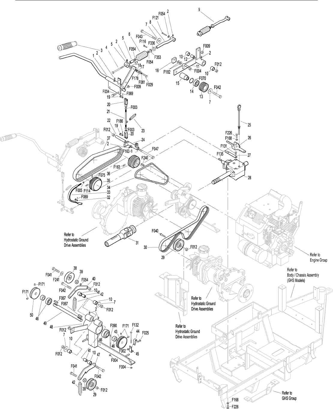
MAIN COMPONENT POWER TRANSMISSION (SD MODELS)
Clutch Lever Assembly
1 6358-1 Clutch Lever (Includes Items # 2 & 3) 1
2 5830 Grease Fitting 6
3 7860 Handle Grip 1
4 7303-10 Clutch Actuator Bolt (3/8) 1
5 7380-5 Knuckle Joint, 3/8 ID 1
6 7226-10 Compression Spring (3/4 x 2-1/2) 1
7 5841 Retainer Washer 4
8 6130-5 Push Rod, Clutch Actuator 1
9 6130-10 Clutch Actuator Rod Assembly 1
(Includes Items # 2, 4-6, 8,
F054, F336 & F353)
10 7201-3 DU Bearing 6
11 8368 PTO Belt Tightener 1
12 7201-5 Inner Race (2-1/4) 1
13 8243-1 Clutch Idler Pulley 1
8243 Clutch Idler Pulley Assembly 1
(Includes Items # 14, 15 & F070)
14 5265 Bearing (3/4) 1
15 8243-3 Hub, Idler Pulley 1
16 8375 PTO Belt Tightener Stop 1
17 7377 Plastic Washer (1 x .438 x .025) 2
18 7378 Pivot Bearing (7/16 x 9/16) 1
19 5281-5 Clevis Pin (1/4 x 0.80) 2
20 5280 Clevis (1/4) 2
21 8305 Brake Actuator Rod 1
22 8370 Bearing, Brake Actuator 1
23 8250 Brake Spring (1/2 x 2-1/2) 1
24 8369 Brake Actuator (Includes Items # 2 & 22) 1
PTO Drive Shaft Assembly
25 7050-1 Dipstick, Gearbox 1
26 8371-1 Mount Bracket, Brake Band 1
27 8377 Brake Band Guide 1
28 8050 PTO Gearbox 1
29 5245 Idler Pulley (3") 2
30 7248 Ground Drive Belt, Micro-V 1
31 7275-15 Universal Joint Tube Assembly 1
32 7523-2 Clevis Pin (1/4 x 5/8) 1
33 8304 Brake Band (14-1/2) 1
34 6250 Drive Belt (3VX375) 1
35 7236 PTO Drive Pulley 1
(Includes Items # F075 & F114)
36 8237 Engine Pulley (Includes Item # F163) 1
37 8230 Engine PTO Belt 1
Jackshaft Assembly
38 7245-1 Idler Pulley (3/8 Groove) 1
39 6325-2 Spacer Bushing (5/16) 2
40 7349-13 Idler Arm 1
41 7210-4 Inner Race (1-1/2) 2
42 5221 Extension Spring (3/4 x 4) 2
43 7241-2 Transmission Drive Pulley, Micro-V 1
(Includes Item # F171)
44 7833 Cable Clamp (7/8 x 1/4) 1
45 8539 Starter Relay Mount 1
46 5268 Bearing (3/4) 2
47 8349 Transmission Belt Tightener Arm 1
48 8393 Jackshaft Support 1
49 8273 Jackshaft (3/4 x 7-1/2) 1
50 7240-1 Jackshaft Drive Pulley 1
(Includes Item # F171)
7240-2 Jackshaft Drive Pulley (2-3/4 / 3V) *
Fasteners
F002 10-24 Keps Nut 1
F003 1/4-28 Hex Nut 2
F004 1/4-20 Keps Nut 3
F005 1/4-20 ESNA Nut 1
F009 5/16-18 Whiz Locknut 3
F012 3/8-16 Keps Nut 8
F025 10-24 x 3/8 PPHMS 1
F029 1/4-20 x 1/2 Hex Bolt 1
F034 5/16-18 x 3/4 Hex Bolt 2
F040 3/8-16 x 1-1/2 Hex Bolt 1
F041 3/8-16 x 1-3/4 Hex Bolt 2
F042 3/8-16 x 2-1/4 Hex Bolt 3
F043 3/8-16 x 3 Hex Bolt 1
F047 3/8-16 x 4-1/2 Hex Bolt 1
F054 AN960616 Washer 4
F061 1/4 Internal Star Lock Washer 1
F067 3/16 x 3/16 x 1 Key 2
F069 3/32 x 1/2 Cotter Pin 2
F070 1-3/4 Internal Snap Ring 1
F075 5/16-18 x 1/2 SQH Set Screw 1
F090 1/4-20 x 2-1/2 Hex Bolt 1
F114 5/16-18 x 5/8 SQH Set Screw 1
F116 1/4-20 x 1-1/4 Hex Bolt 1
F121 5/16-18 x 3/8 x 1 SHL Bolt 1
F131 5/16-18 x 1/2 Hex Bolt 2
F132 1/4-20 x 2-3/4 Hex Bolt 1
F135 3/16 x 3/16 x 1-3/4 Key 1
F163 5/16-18 x 3/4 SQH Set Screw 2
F168 5/16 Split Lock Washer 6
F171 5/16-18 x 3/8 Set Screw 4
F178 1/4 x 1 Fender Washer 1
F182 5/8 x 1/4 x 1/8 Washer 2
F186 5/64 x 1/2 Cotter Pin 1
F226 5/16-18 x 7/8 Hex Bolt 6
F240 1/4 x 1/4 x 2-1/4 Key 1
F241 .375 x .875 x .10 Washer 1
F336 3/8-16 Jam Nut 1
F353 3/8-16 ESNA LP Nut 1
*May be ordered as a kit for dealer installation. Contact your
Walker dealer.
13
Effective Date 12-01-00 Use only genuine Walker® replacement parts.
MAIN COMPONENT POWER TRANSMISSION (SD MODELS)

14
ITEM PART DESCRIP TION NO.
NO. NO. REQ’D ITEM PART DESCRIP TION NO.
NO. NO. REQ’D
Use only genuine Walker®replacement parts. Effective Date 12-01-00
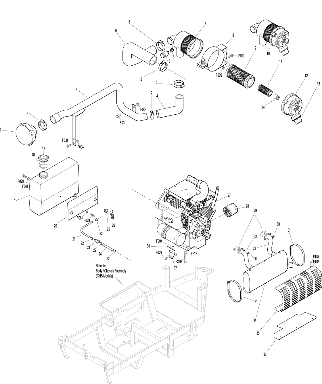
ENGINE GROUP
Precleaner Assembly
1 7026-2 Remote Precleaner (Includes Item # 2) 1
2 7840 Hose Clamp (1-5/16 to 2-1/4) 3
3 6028-1 Precleaner Tube 1
4 7027 Elbow, Precleaner 1
5 6029 Hose Clamp (2-1/2) 2
6 6087 Air Intake Hose 1
7 6090 Air Cleaner (Includes Item #11) 1
8 5088-1 Air Cleaner Band 1
9 5090-1 Air Cleaner Cartridge 1
10 6090-10 Air Cleaner Assembly *
(Includes Items # 7, 9, 11-13, 15 & 16)
11 5090-3 Safety Filter 1
12 5088-11 Air Cleaner Cap 1
13 5090-2 Vacuator Valve 1
14 5088-5 Air Cleaner Draw Latch 1
15 5091-9 Elbow, Brass 90° 1
16 5091-10 Air Flow Indicator & Nipple 1
Fuel Tank Assembly
17 5082 Fuel Tank Cap *
(Includes Item # 18)
18 5082-2 Fuel Cap Seal *
19 6046 Fuel Tank, 3.0 gal., Gas 1
(Includes Items # 17, 18, 25 & 26)
20 8023 Fuel Tank Support 1
21 8015-2 Fuel Line, Tank (1/4 x 15) 1
22 5879-3 Hose Clamp (1/2) 4
23 5020 Fuel Filter 1
24 6015-3 Fuel Line, Engine (1/4 x 12-1/2) 1
25 5083-1 Bushing, Rubber *
26 5083 Fuel Shut-Off Valve & Filter *
Engine & Exhaust Assemblies
27 NS 16 HP Engine 1
(Kohler TH16S, Spec. # 52518)
28 NS Oil Filter (Kohler 2805001) 1
29 NS Gasket (Kohler 2404102) 2
30 NS Nut (Kohler M-0841080) 4
31 8897 Muffler Band Clamp 2
32 6052 Exhaust Pipe, Rear 1
33 6051 Exhaust Pipe, Front 1
34 8013-1 Muffler 1
35 8013-5 Muffler Heat Shield 1
36 8013-7 Muffler Heat Deflector 1
37 NS Starter Solenoid (Kohler 2543502) 1
38 6327 Solenoid Mount 1
Fasteners
F004 1/4-20 Keps Nut 5
F009 5/16-18 Whiz Locknut 2
F029 1/4-20 x 1/2 Hex Bolt 4
F031 1/4-20 x 5/8 Hex Bolt 3
F061 1/4 Internal Star Lock Washer 2
F091 5/16-18 x 5/8 Hex Bolt 2
F184 1/4-20 x 1/2 Hex Bolt SS 6
F185 1/4 Internal Star Lock SS 6
F218 7/16 Split Lock Washer 4
F219 7/16-14 x 1-1/4 Hex Bolt 4
*Service Part Only
NOTE: Refer to Kohler Engine Decal (NS) for Engine Identifica-
tion Numbers.
15
Effective Date 12-01-00 Use only genuine Walker® replacement parts.
ENGINE GROUP

16
ITEM PART DESCRIP TION NO.
NO. NO. REQ’D ITEM PART DESCRIP TION NO.
NO. NO. REQ’D
Use only genuine Walker® replacement parts. Effective Date 12-01-00
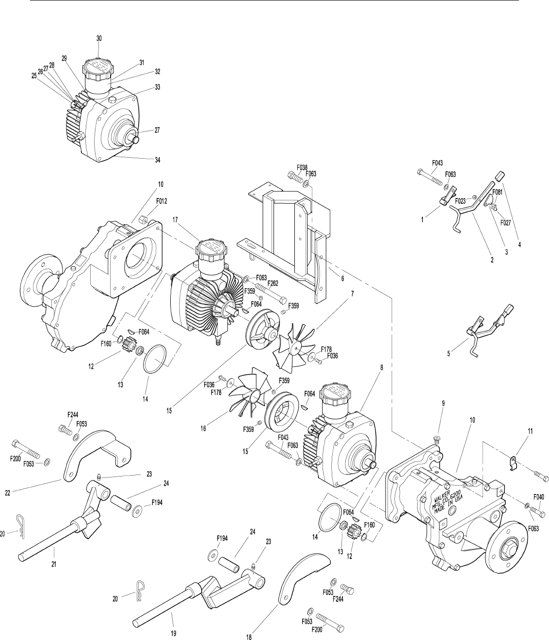
HYDROSTATIC GROUND DRIVE ASSEMBLIES
Transmission Lockout Assembly
1 5027 Lockout Mount 2
2 5028 Lockout Lever 2
3 5057 Lockout Cam 2
(Includes Item # F081)
4 5847 Plastic Tip 2
5 5028-3 Transmission Lockout Assembly *
(Includes Items # 1-4, F023 & F027)
Ground Drive Assemblies
6 6209-1 Bridge Assembly 1
7 6243-2 Hydro Fan, CCW 1
8 5026 Hydrostatic Drive, CW (700-041) 1
9 6206 Pressure Relief Valve *
10 6200-7 Gear Axle Drive Assembly 2
(Includes Item # 9)
11 5126 Cable Retainer 1
(Uses Existing Bolt on
Gear Axle Drive Assembly)
12 6233-1 Pinion Gear 2
13 6234 Spacer, Pinion Gear 2
14 6201 O-Ring Seal 2
15 7244 Hydro Pulley (3-7/8) 2
16 6243-1 Hydro Fan, CW 1
17 5025 Hydrostatic Drive, CCW (700-042) 1
Deck Support Arm Assemblies
18 6430-10 Outboard Mount, LH 1
19 6430-2 Deck Support Arm, LH 1
(Includes Item # 23)
20 5775-2 Hitch Pin (#6) 2
21 6430-1 Deck Support Arm, RH 1
(Includes Item # 23)
22 6430-9 Outboard Mount, RH 1
23 5830 Grease Fitting 2
24 6840-1 Support Arm Bushing 2
Transmission Repair Parts*
25 5025-5 Input Shaft *
26 5025-8 Bearing, Input *
27 5025-7 Snap Ring *
28 5025-2 Seal, Input Shaft *
29 5022 Reservoir to Casting Gasket *
30 5024 Reservoir Cap and Gasket *
31 5023 Transmission Reservoir Kit *
(Includes Items # 29, 30 & 32)
32 5023-1 Rubber Bladder *
33 5025-6 O-Ring & Plug Assembly *
34 5025-3 Seal, Control Shaft *
Fasteners
F012 3/8-16 Keps Nut 1
F023 10-24 ESNA Nut 2
F027 10-24 x 5/8 PPHMS 2
F036 1/4-20 x 1/2 SBH Screw 2
F038 3/8-16 x 1 Hex Bolt 4
F040 3/8-16 x 1-1/2 Hex Bolt 4
F043 3/8-16 x 3 Hex Bolt 7
F053 7/16 Internal Star Lock Washer 4
F063 3/8 Internal Star Lock Washer 16
F064 1/8 x 1/2 Woodruff Key (#3) 4
F081 A/A45D Aluminum Pop Rivet 2
F160 External Snap Ring (.669 Shaft) 2
F178 1/4 x 1 Fender Washer 2
F194 7/16 x 1-1/4 x 1/8 Washer 2
F200 7/16-20 x 3 Grade 8 Bolt 2
F244 7/16-20 x 3/4 Hex Bolt 2
F262 3/8-16 x 4 Hex Bolt (Spec) All Thread 1
F359 5/16-18 x 5/16 Set Screw
(Unbrako Knurl Point) 4
*Service Part Only
17
Effective Date 12-01-00 Use only genuine Walker® replacement parts.
HYDROSTATIC GROUND DRIVE ASSEMBLIES

18
ITEM PART DESCRIP TION NO.
NO. NO. REQ’D ITEM PART DESCRIP TION NO.
NO. NO. REQ’D
Use only genuine Walker® replacement parts. Effective Date 12-01-00
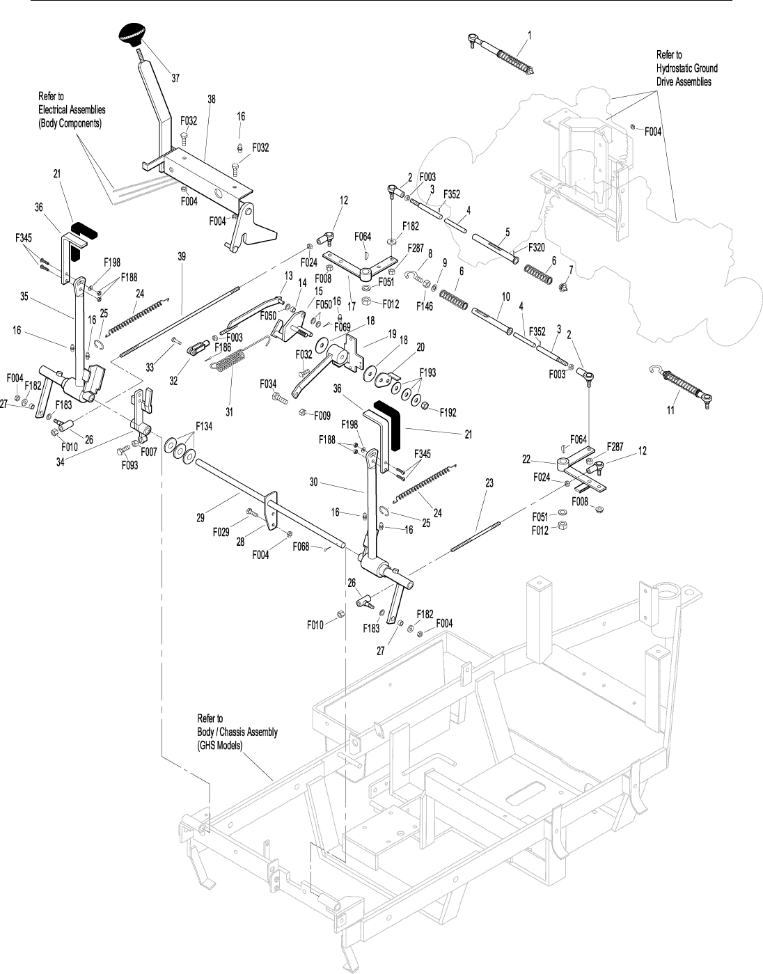
STEERING CONTROL ASSEMBLIES
Transmission Spring Assemblies
1 6199 Transmission Spring Assembly (RH) *
(Includes Items # 2-7, F003,
F287, F320 & F352)
2 5552 Ball Joint (1/4-28) 2
3 5192-1 Spring Plunger (5/32) Hole 2
4 5194 Plunger Sleeve 2
5 6191 Spring Slide (4-3/4) 1
6 5195 Compression Spring (1 x 5-1/8) 2
7 6196 Spring Slide Cap 1
8 5197 J-Bolt 1
9 5193 Washer (.750 ID x 1.00 OD x .085) 1
10 5191 Spring Slide (3-5/8) 1
11 5199 Transmission Spring Assembly (LH) *
(Includes Items # 2-4, 6, 8-10,
F003, F146, F287 & F352)
Steering Lever & FSC Assemblies
12 5214-2 Ball Joint (5/16-24), Nylon Lined 2
13 5173 FSC Actuator Rod 1
(Includes Items # 33 & F003)
14 5172 Bearing, Nylon (.255 ID x .379 OD x .250) 1
15 5142-2 FSC Actuator Cam 1
16 5830 Grease Fitting 6
17 6212 Transmission Control Arm, RH 1
18 5141 FSC Friction Washer 2
19 5140-15 FSC Friction Body 1
(Includes Item # 16)
20 5142-7 FSC Key 1
5140-13 FSC Control Assembly *
(Includes Items # 16, 18-20, 31,
F192 & F193)
21 5850-2 Handle Grip, Foam (5-1/2) 2
22 5212-2 Transmission Control Arm, LH 1
23 5213-2 Control Rod, LH (6") 1
24 5223 Extension Spring (1/4 x 5-1/2) 2
25 5450 D-Clip 2
26 5463 Steering Lever Actuator 2
27 5214-1 Bearing, Steering Lever Actuator 2
28 5391-3 Steering Lever Support 1
29 5217 Pivot Pin, Steering Lever 1
30 5451-3 Steering Lever Assembly, LH 1
(Includes Items # 16, 21, 36,
F188, F198 & F345)
5451-5 Adjustable Steering Lever Arm, LH 1
31 5219 FSC Extension Spring (3/4 x 6-3/4) 1
32 5280 Clevis (1/4) 1
33 5281-5 Clevis Pin (1/4 x 0.80) 1
34 5470-1 Speed Control Stop 1
35 5450-3 Steering Lever Assembly, RH 1
(Includes Items # 16, 21, 36,
F188, F198 & F345)
5450-5 Adjustable Steering Lever Arm, RH 1
36 5453-10 Adjustable Steering Lever Handle 2
(Includes Items # 21 & F345)
37 5862 FSC Knob 1
38 7170 FSC Lever Assembly 1
(Includes Item # 16)
39 5213-1 Control Rod, RH (15") 1
Fasteners
F003 1/4-28 Hex Nut 3
F004 1/4-20 Keps Nut 8
F007 5/16-18 Jam Nut 1
F008 5/16-24 Keps Nut 2
F009 5/16-18 Whiz Locknut 1
F010 5/16-24 ESNA Nut 2
F012 3/8-16 Keps Nut 2
F024 5/16-24 Jam Nut 2
F029 1/4-20 x 1/2 Hex Bolt 2
F032 1/4-20 x 3/4 Hex Bolt 4
F034 5/16-18 x 3/4 Hex Bolt 1
F050 1/4 SAE Washer 3
F051 3/8 SAE Washer 2
F064 1/8 x 1/2 Woodruff Key (#3) 2
F068 1/8 x 1 Cotter Pin 1
F069 3/32 x 1/2 Cotter Pin 1
F093 5/16-18 x 1 Hex Bolt 1
F134 AN960816L Washer 3
F146 1/4-20 Jam Nut 1
F182 1/4 x 5/8 x 1/8 Washer 3
F183 .312 x .700 x .074 Washer 2
F186 5/64 x 1/2 Cotter Pin 1
F188 1/4-20 Self-Locking Nut 4
F192 3/8-24 Self-Locking Nut 1
F193 3/8 Belleville Spring Washer 3
F198 .250 x .625 x .040 Washer, SS 2
F287 1/4-28 Keps Nut 2
F320 1/8 x 3/4 Split Spring Pin 1
F345 1/4-20 x .770 Knurled Bolt 4
F352 5/32 x 1 Hvy Duty Roll Pin 2
*Service Part Only
19
Effective Date 12-01-00 Use only genuine Walker® replacement parts.
STEERING CONTROL ASSEMBLIES

20
ITEM PART DESCRIP TION NO.
NO. NO. REQ’D ITEM PART DESCRIP TION NO.
NO. NO. REQ’D
Use only genuine Walker® replacement parts. Effective Date 12-01-00
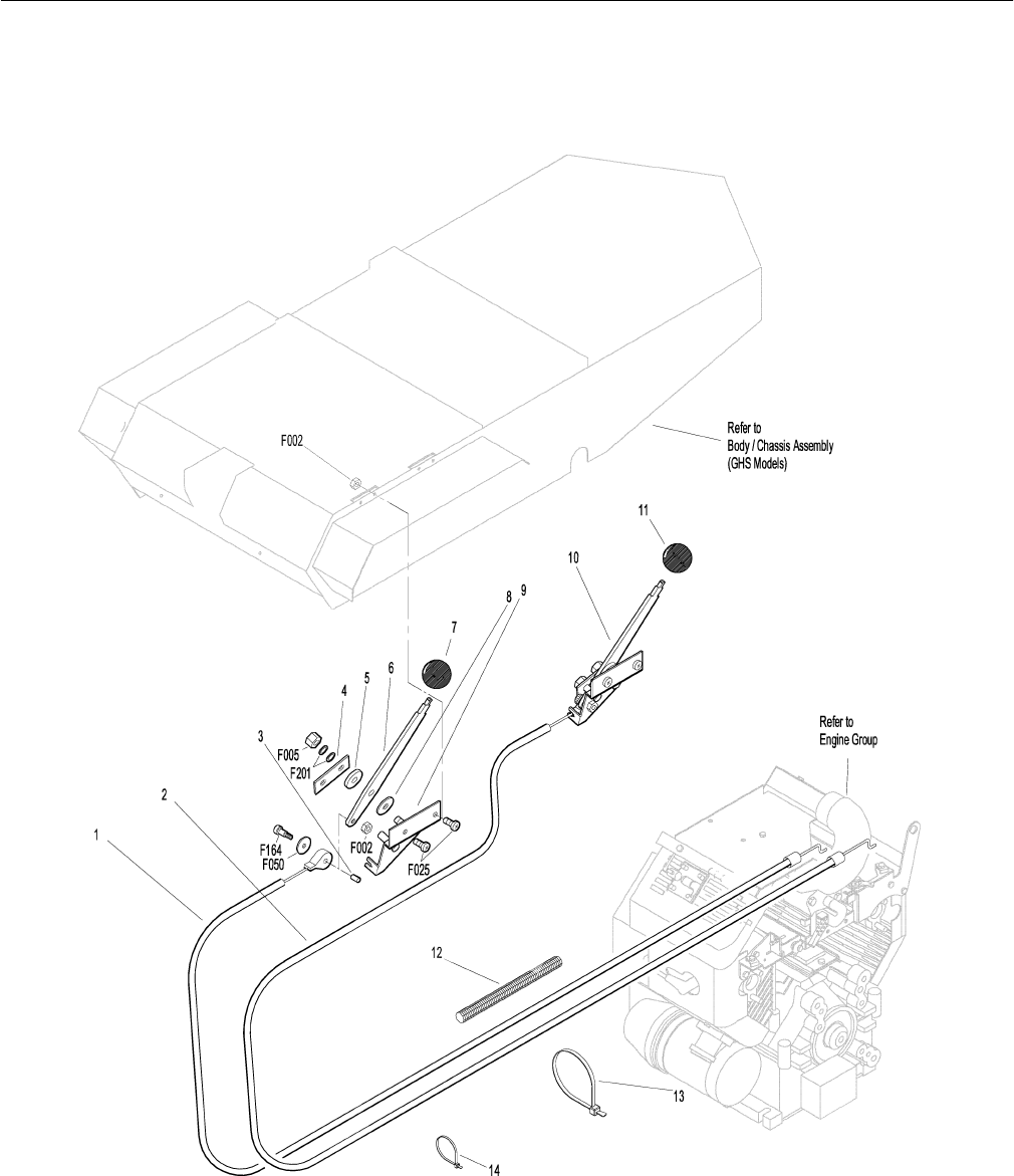
THROTTLE & CHOKE CONTROL ASSEMBLIES
Throttle & Choke Control Assemblies
1 8121-1 Throttle Cable 1
2 8122-1 Choke Cable 1
3 5172 Nylon Bearing 2
4 5108-7 Control Lock Tab 2
5 5108-10 Friction Washer (.125) 2
6 5108-1 Control Lever, Throttle & Choke 2
7 5108-5 Throttle Control Knob, Red 1
8 5108-11 Friction Washer (.062) 2
9 5108-8 Control Bracket 2
10 7108 Control Assembly, Throttle and Choke 2
8121 Complete Throttle Control and Cable *
Assembly (Includes Item # 7)
8122 Complete Choke Control and Cable *
Assembly (Includes Item # 11)
11 5108-6 Choke Control Knob, Black 1
12 8123 Insulation Sleeve (3/8 x 6) 1
13 5975-3 Cable Tie (50# x 7") 1
14 5975-1 Cable Tie (18# x 3-3/4") 1
Fasteners
F002 10-24 Keps Nut 6
F005 1/4-20 ESNA Nut 2
F025 10-24 x 3/8 PPHMS 4
F050 1/4 SAE Washer 2
F164 10-24-1/4 x 3/8 SHL Bolt 2
F201 1/4 Belleville Spring Washer 4
*Service Part Only
21
Effective Date 12-01-00 Use only genuine Walker® replacement parts.
THROTTLE & CHOKE CONTROL ASSEMBLIES

22
ITEM PART DESCRIP TION NO.
NO. NO. REQ’D ITEM PART DESCRIP TION NO.
NO. NO. REQ’D
Use only genuine Walker® replacement parts. Effective Date 12-01-00
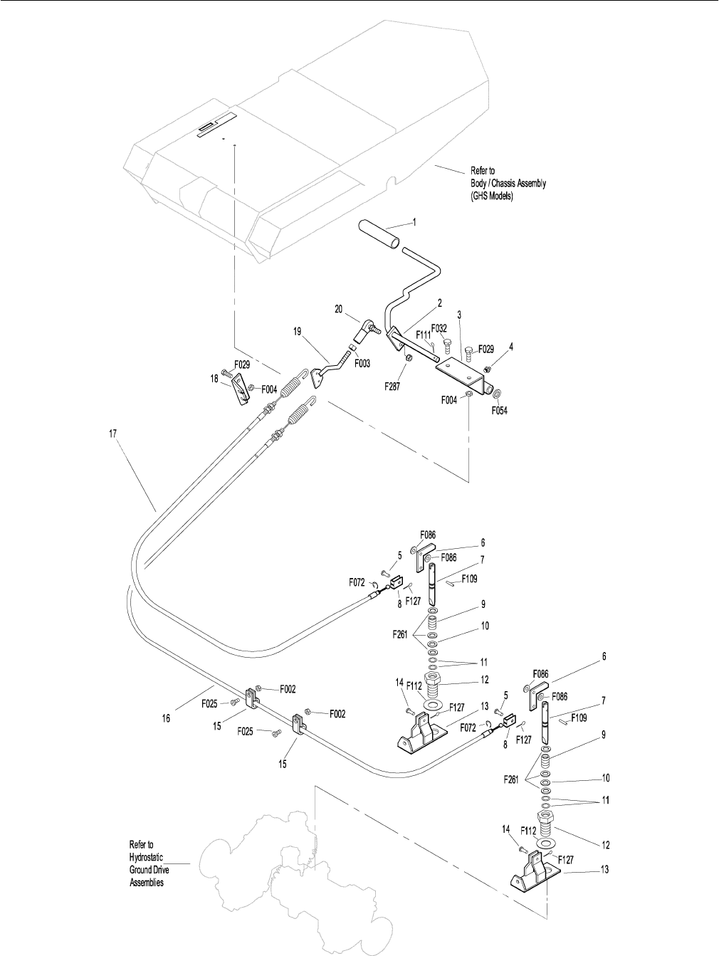
PARKING BRAKE ASSEMBLY
Parking Brake Assembly
1 7406-1 Handle Grip, Red 1
2 7406-5 Parking Brake Lever 1
3 7406-2 Lever Mount 1
4 5830 Grease Fitting 1
5 7407 Clevis Pin (3/16 x 1/2) 2
6 7404 Brake Actuator Arm 2
7 7405 Pin, Transmission Lock 2
8 7402 Clevis 2
9 7408 Compression Spring (1/2 x 3/4) 2
10 7415 Rubber Dust Shield (5/8 x 3/8 x 1/32) 2
11 5567-3 O-Ring Seal (1/4 x 3/8) 4
12 7403 Plunger Bushing, Gear Axle 2
13 7404-1 Brake Actuator Mount 2
14 7412 Clevis Pin (3/16 x 3/4) 2
15 5833 Cable Clamp (1/4) 2
16 7410 Brake Control Cable, LH (27") 1
17 7409 Brake Control Cable, RH (21") 1
18 7401-3 Cable Mount Bracket 1
19 7401-1 Cable Pull Rod 1
20 5552 Ball Joint (1/4-28) 1
Fasteners
F002 10-24 Keps Nut 2
F003 1/4-28 Hex Nut 1
F004 1/4-20 Keps Nut 4
F025 10-24 x 3/8 PPHMS 2
F029 1/4-20 x 1/2 Hex Bolt 3
F032 1/4-20 x 3/4 Hex Bolt 1
F054 AN960616 Washer 1
F072 1/4 “E” Retainer Ring 2
F086 #10 SAE Washer 4
F109 1/8 x 5/8 Roll Pin 2
F111 1/8 x 3/4 Cotter Pin 1
F112 5/8 x 1-1/4 x .03 Washer 2
F127 1/16 x 1/2 Cotter Pin 4
F261 AN960616L Washer 6
F287 1/4-28 Keps Nut 1
23
Effective Date 12-01-00 Use only genuine Walker® replacement parts.
PARKING BRAKE ASSEMBLY

24
ITEM PART DESCRIP TION NO.
NO. NO. REQ’D ITEM PART DESCRIP TION NO.
NO. NO. REQ’D
Use only genuine Walker® replacement parts. Effective Date 12-01-00
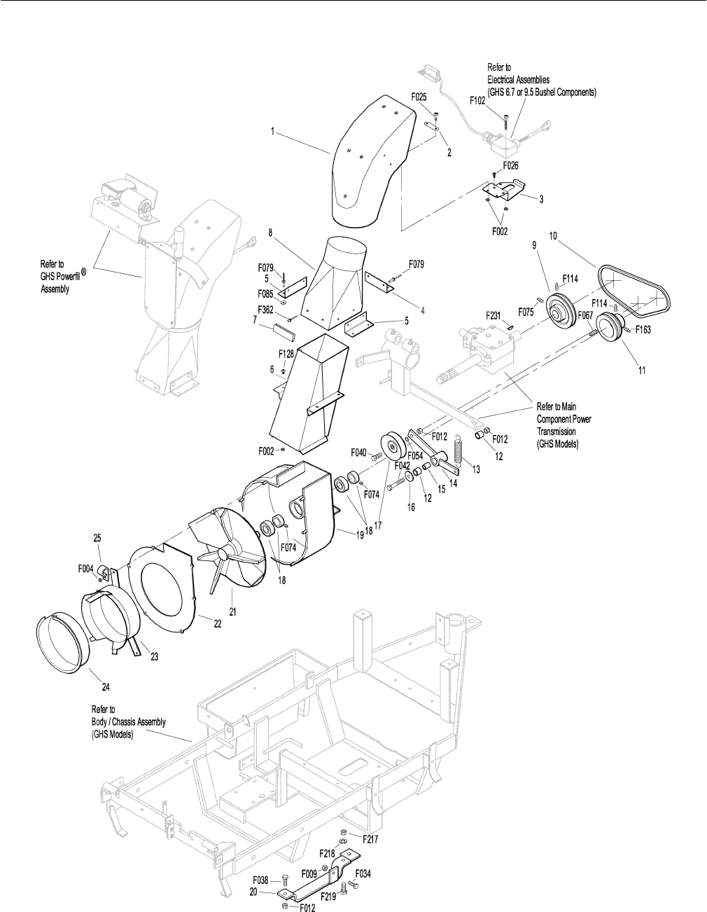
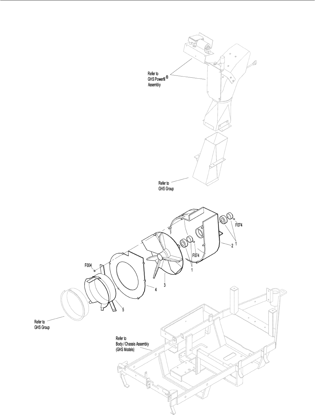
GHS GROUP
Delivery Chute Assembly
When Optional 9.5 Bushel Catcher Assembly is purchased, Item #
6 is replaced by P/N 7530 (Body Chute), and Item # 8 is replaced
by P/N 8511-1 (Delivery Chute Assembly, 9.5).
1 5515-2 Elbow Delivery Spout Assembly 1
2 5592-13 Backing Plate, Grass-Pak® Switch 1
3 5592-12 Mount Plate, Grass-Pak® Switch 1
4 5578 Rear Clip, Chute Mount 1
5 5577 Side Clip, Chute Mount 2
6 6530 Body Chute (10") 1
7 5578-10 Front Clip, Chute Mount 1
8 5511-3 Delivery Chute Assembly, (6.7) 1
(Includes Items # 4, 5, 7,
F079, F085 & F362)
Blower Belt Tightener Assembly
9 7238 Blower Drive Pulley (4-1/4 / 3V) 1
10 7234 Blower Belt (3VX280) 1
11 7239-2 Blower Pulley (3-3/8 / 3V) 1
12 7201-3 DU Bearing 2
13 5221 Extension Spring (3/4 x 4) 1
14 7364 Blower Belt Tightener Arm 1
15 7201-4 Inner Race (1-1/2) 1
16 5841 Retainer Washer 1
17 7245 Idler Pulley (1/2 Groove) 1
Blower Assembly
18 5268 Bearing (3/4) Includes Locking Collar 2
19 6543 Housing (10" Blower) 1
6542 Blower Assembly (10") *
20 7528 Skid Bar (10" Blower) 1
21 6545 Blower Wheel (10") 1
22 6525-2 Faceplate (10" Blower) 1
23 6526 Intake Tube (6-1/2 x 2-1/2) 1
24 5595-2 Intake Cover **
25 7833 Cable Clamp (7/8 x 1/4) 1
Fasteners
F002 10-24 Keps Nut 8
F004 1/4-20 Keps Nut 6
F009 5/16-18 Whiz Locknut 1
F012 3/8-16 Keps Nut 3
F025 10-24 x 3/8 PPHMS 2
F026 10-24 x 1/2 PPHMS 2
F034 5/16-18 x 3/4 Hex Bolt 1
F038 3/8-16 x 1 Hex Bolt 1
F040 3/8-16 x 1-1/2 Hex Bolt 1
F042 3/8-16 x 2-1/4 Hex Bolt 1
F054 AN960616 Washer 1
F067 3/16 x 3/16 x 1 Key 1
F074 1/4-20 x 3/8 Set Screw 2
F075 5/16-18 x 1/2 SQH Set Screw 1
F079 A/A66D Aluminum Pop Rivet 12
F085 3/16 Rivet Backup Washer 6
F102 10-24 x 1-1/2 PTHMS 2
F114 5/16-18 x 5/8 SQH Set Screw 2
F128 10-24 x 3/8 PTHMS 4
F163 5/16-18 x 3/4 SQH Set Screw 1
F217 7/16-14 Hex Nut 1
F218 7/16 Split Lock Washer 1
F219 7/16-14 x 1-1/4 Hex Bolt 1
F231 1/4 x 3/4 Woodruff Key (#806) 1
F362 A/A62D Alum. Pop Rivet (3/16D x 13/32L) 2
*Service Part Only
** Plugs blower when GHS is not in use. Furnished only with
Mulching Decks, SD Decks used on a GHS Tractor, Rotary
Broom Attachment and Snowblower Attachment.
25
Effective Date 12-01-00 Use only genuine Walker® replacement parts.
GHS GROUP

26
ITEM PART DESCRIP TION NO.
NO. NO. REQ’D ITEM PART DESCRIP TION NO.
NO. NO. REQ’D
Use only genuine Walker® replacement parts. Effective Date 12-01-00
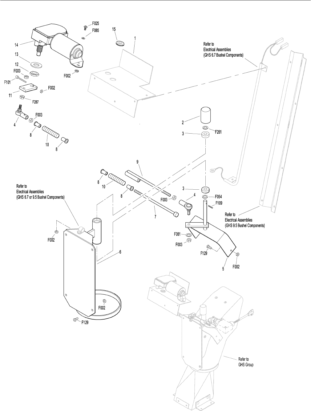
GHS POWERFIL® ASSEMBLY
GHS Powerfil® Assembly
1 5557 Motor Mount, Powerfil®1
2 5551-3 Bearing Cap, Powerfil®1
3 5551-1 Pivot Bearing (#S3PP) 2
4 5552 Ball Joint (1/4-28) 2
5 5518-2 Pivot, Delivery Spout 1
6 5517-2 Pivot Mount 1
7 5558-1 Powerfil® Push Rod 1
8 5553-3 Bushing, Powerfil® Actuator 4
9 5558-2 Powerfil® Actuator Rod 1
5549 Actuator Rod Assembly *
(Includes Items # 4, 7-10 & F003)
10 5553-1 Spring, Powerfil® Actuator 2
11 5554 Actuator Arm 1
12 5519-3 Motor Mount Nut (5/8-24 Panel Nut) *
13 5519-2 Motor Mount Washer *
14 5519 Actuator Motor (12/24V) 1
(Includes Items # 12 & 13)
15 5977 Grommet (1/2 ID x 7/8 OD x 1/16) 1
Fasteners
F002 10-24 Keps Nut 9
F003 1/4-28 Hex Nut 4
F025 10-24 x 3/8 PPHMS 1
F054 AN960616 Washer 1
F061 1/4 Internal Star Lock Washer 1
F085 3/16 Rivet Backup Washer 1
F101 10-24 x 1-1/4 SHC Screw 1
F109 1/8 x 5/8 Roll Pin 1
F129 10-24 x 1/2 PTHMS 7
F261 AN960616L Washer 1
F287 1/4-28 Keps Nut 1
*Service Part Only
27
Effective Date 12-01-00 Use only genuine Walker® replacement parts.
GHS POWERFIL® ASSEMBLY

28
ITEM PART DESCRIP TION NO.
NO. NO. REQ’D ITEM PART DESCRIP TION NO.
NO. NO. REQ’D
Use only genuine Walker® replacement parts. Effective Date 12-01-00
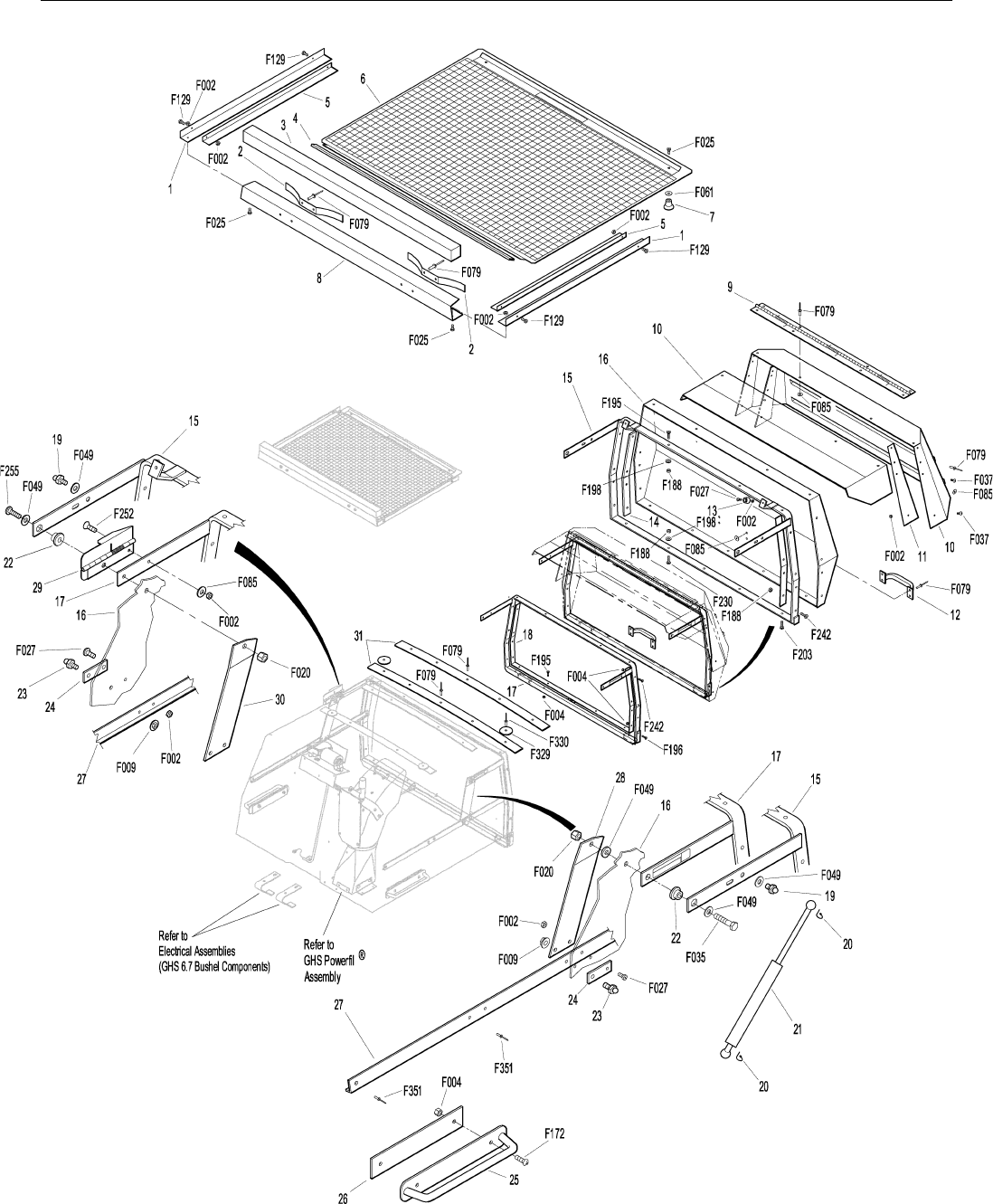
GHS 6.7 BUSHEL CATCHER & EXHAUST DEFLECTOR ASSEMBLIES
Upper Baffle Screen Assembly (Removable)
1 7509-3 Channel Bottom 2
2 7505 Mustache Spring 2
3 6507 Screen Seal, 6.7 (24") 1
4 6856-1 Edge Molding, 6.7 (21-3/4) 1
5 7509-2 Channel Top 2
6 6512-2 Removable Screen (6.7) 1
7 7506 Knob 2
8 6509-4 C-Channel (6.7) 1
Exhaust Deflector Assembly
5504 Exhaust Deflector Kit, 6.7 *
9 5504-3 Hinge, Exhaust Deflector 1
10 5504-1 Exhaust Deflector (Two Piece Set) 1
11 5504-8 Deflector Mount Doubler 2
GHS 6.7 Bushel Catcher Assembly
12 5583 Handle 1
13 5588 Rubber Bumper (.75 OD x .50) 2
14 5130 Side Strap, Door (6.7) 2
15 5514-10 Door Frame, Catcher (6.7) 1
16 5510-1 6.7 Bushel Catcher, Including Door 1
5502-1 6.7 Catcher, Without Powerfil®**
(Includes Door)
5502-2 6.7 Catcher Assembly **
(Includes Powerfil® )
5502-3 6.7 Catcher Assembly **
and Bumper Mount
(Includes Bumper & Powerfil®)
17 5503-2 Mounting Frame, Catcher (6.7) 1
18 5513-1 Mounting Frame Doubler (6.7) 1
19 5155-12 5/16 Ball Stud 2
20 5147 Spring Clip, Gas Spring 4
21 5155-10 Catcher Gas Spring Assembly 2
(Includes Items # 19, 20 & 23)
22 5524-1 Flanged Hinge Bearing 2
23 5155-13 3/4 Ball Stud 2
24 5523-6 Gas Spring Plate 2
25 7532 Handle, Catcher Lift 2
7534 Catcher Handle Kit *
(Includes Items # 25, 26, F004 & F172)
26 7533 Backing Plate, Handle 2
27 5155-15 Box Support, Gas Spring 2
28 5522-1 Hinge Backup Plate, LH 1
29 6508 Safety Latch Hinge 1
30 5522-2 Hinge Backup Plate, RH 1
31 5584 Reinforcing Strap, Catcher Top 1
5598 Optional Dump Bag (Not Shown)
May be ordered as an option. Contact your Walker dealer.
Fasteners
F002 10-24 Keps Nut 15
F004 1/4-20 Keps Nut 16
F009 5/16-18 Whiz Locknut 2
F020 5/16-18 ESNA Nut 2
F025 10-24 x 3/8 PPHMS 4
F027 10-24 x 5/8 PPHMS 4
F035 5/16-18 x 1-1/4 Hex Bolt 1
F037 10-24 x 5/8 PTH Screw 4
F049 5/16 SAE Washer 4
F061 1/4 Internal Star Lock Washer 2
F079 A/A66D Aluminum Pop Rivet 27
F085 3/16 Rivet Backup Washer 13
F129 10-24 x 1/2 PTHMS 4
F172 1/4-20 x 3/4 Carriage Bolt 4
F188 1/4-20 Self Locking Nut 17
F195 1/4-20 x 3/4 PPHMS SS 8
F196 1/4-20 x 1 PPHMS SS 2
F198 .625 x .250 x .040 Washer, SS 9
F203 1/4-20 x 5/8 PPHMS SS 4
F230 1/4-20 x 1-1/4 PPHMS SS 1
F242 1/4-20 x 7/8 PPHMS SS 14
F252 10-24 x 3/4 PFHMS 1
F255 5/16-18 x 1-1/2 Hex Bolt 1
F329 .260 ID x 1.939 OD Washer 2
F330 3/16 D x 21/32 L Rivet, SS 2
F351 Aluminum Pop Rivet 6
*This kit is sold as a complete assembly, including mounting
hardware.
** Service Part Only
29
Effective Date 12-01-00 Use only genuine Walker® replacement parts.
GHS 6.7 BUSHEL CATCHER & EXHAUST DEFLECTOR ASSEMBLIES

30
ITEM PART DESCRIP TION NO.
NO. NO. REQ’D ITEM PART DESCRIP TION NO.
NO. NO. REQ’D
Use only genuine Walker® replacement parts. Effective Date 12-01-00
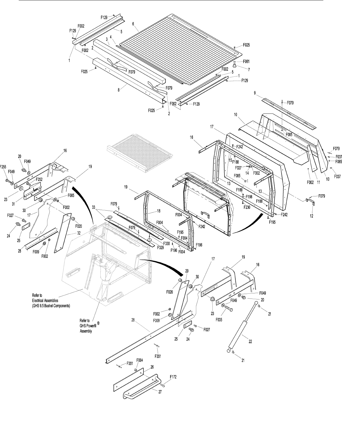
GHS 9.5 BUSHEL CATCHER & EXHAUST DEFLECTOR ASSEMBLIES
Upper Baffle Screen Assembly (Removable)
1 7509-3 Channel Bottom 2
2 7505 Mustache Spring 2
3 7507 7.0 / 9.5 Screen Seal, (27-1/2) 1
4 7856-1 7.0 / 9.5 Edge Molding, (26”) 1
5 7509-2 Channel Top
6 7512-2 7.0 / 9.5 Removable Screen 1
7 7506 Knob
8 7509-4 7.0 / 9.5 C-Channel 1
Exhaust Deflector Assembly
7504 Exhaust Deflector Kit, 7.0 / 9.5 *
9 7504-3 Hinge, Exhaust Deflector 1
10 7504-1 Exhaust Deflector (Two Piece Set) 1
11 7504-8 Deflector Mount Doubler 2
GHS 9.5 Bushel Catcher Assembly**
12 5583 Handle 1
13 8516 Backup Plate, Door Sides 2
14 5588 Rubber Bumper (.75 OD x .50) 2
15 7514-1 Backup Plate, Catcher Door 1
16 8514-11 Door Frame, Catcher (9.5) 1
(Begin S/N 49198)
17 8510-1 9.5 Bushel Catcher, Including Door 1
8502-1 9.5 Catcher Assembly, ***
Without Powerfil® (Includes Door)
8502-2 9.5 Catcher Assembly ***
(Includes Powerfil®)
8502-4 9.5 Catcher Assembly ***
(Includes Frame & Powerfil®)
18 8513-3 Mount Frame Doubler (9.5) 1
(Begin S/N 49198)
19 8503-2 Mounting Frame (9.5) 1
(Begin S/N 49198)
20 5155-12 5/16 Ball Stud 2
21 5147 Spring Clip, Gas Spring 4
22 5155-10 Catcher Gas Spring Assembly 2
(Includes Items # 20, 21 & 24)
23 5524-1 Flanged Hinge Bearing 2
24 5155-13 3/4 Ball Stud 2
25 5523-6 Gas Spring Plate 2
26 7533 Backing Plate, Handle 2
27 7532 Handle, Catcher Lift 2
7534 Catcher Handle Kit *
(Includes Items # 26, 27, F004 & F172)
28 5155-15 Box Support, Gas Spring 2
29 5522-1 Hinge Backup Plate, LH 1
30 7503-9 Pivot Bushing 2
31 7508 7.0 / 9.5 Safety Latch Hinge 1
32 5522-2 Hinge Backup Plate, RH 2
33 7584 Reinforcing Strap, Catcher Top 2
5598 Optional Dump Bag (Not Shown)
May be ordered as an option. Contact your Walker dealer.
Fasteners
F002 10-24 Keps Nut 15
F004 1/4-20 Keps Nut 19
F009 5/16-18 Whiz Locknut 2
F020 5/16-18 ESNA Nut 2
F025 10-24 x 3/8 PPHMS 4
F027 10-24 x 5/8 PPHMS 4
F035 5/16-18 x 1-1/4 Hex Bolt 1
F037 10-24 x 5/8 PTH Screw 4
F049 5/16 SAE Washer 4
F061 1/4 Internal Star Lock Washer 2
F079 A/A66D Aluminum Pop Rivet 33
F085 3/16 Rivet Backup Washer 16
F129 10-24 x 1/2 PTHMS 4
F172 1/4-20 x 3/4 Carriage Bolt 4
F188 1/4-20 Self Locking Nut 20
F195 1/4-20 x 3/4 PPHMS SS 8
F196 1/4-20 x 1 PPHMS SS 3
F198 .625 x .250 x .040 Washer, SS 5
F230 1/4-20 x 1-1/4 PPHMS SS 1
F242 1/4-20 x 7/8 PPHMS SS 23
F252 10-24 x 3/4 PFHMS 1
F255 5/16-18 x 1-1/2 Hex Bolt 1
F329 .260 ID x 1.939 OD Washer 2
F330 3/16 D x 21/32 L Rivet, SS 2
F351 Aluminum Pop Rivet 6
*This kit is sold as a complete assembly, including mounting
hardware.
** May be ordered as a factory-installed option.
Contact your Walker dealer.
*** Service Part Only
31
Effective Date 12-01-00 Use only genuine Walker® replacement parts.
GHS 9.5 BUSHEL CATCHER & EXHAUST DEFLECTOR ASSEMBLIES

32
ITEM PART DESCRIP TION NO.
NO. NO. REQ’D ITEM PART DESCRIP TION NO.
NO. NO. REQ’D
Use only genuine Walker® replacement parts. Effective Date 12-01-00
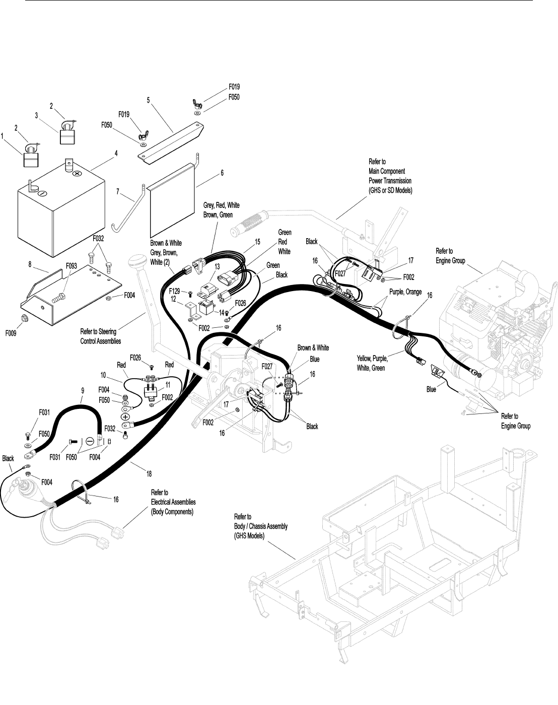
ELECTRICAL ASSEMBLIES (CHASSIS COMPONENTS)
Battery Assembly
1 5932 Battery Terminal Insul., Black (-) 1
2 5975-1 Cable Tie (18# x 3-3/4") 2
3 5933 Battery Terminal Insul., Red (+) 1
4 5910 Battery (12V U1-SP30, Dry) 1
5 5844 Battery Hold-Down Bar 1
6 6392 Battery Protector Plate 1
7 5839 Hook Bolt 2
8 6390 Battery Pan 1
9 6923 Negative Battery Cable 1
10 8943 Positive Battery Lead Wire 1
Harness Assembly
11 8941 Circuit Breaker (30 Amp) with Reset 1
12 7672 Mount Bracket 1
13 7948-1 Time Delay Module 1
14 6941 Relay Switch (30/40 Amp) 1
15 7948-5 Time Delay Harness 1
16 5975-3 Cable Tie (50# x 7") 6
17 5942-5 Safety Switch 2
18 6940-4 Wire Harness 1
Fasteners
F002 10-24 Keps Nut 9
F004 1/4-20 Keps Nut 5
F009 5/16-18 Whiz Locknut 1
F019 1/4-20 ESNA Wing Nut 2
F026 10-24 x 1/2 PPHMS 3
F027 10-24 x 5/8 PPHMS 4
F031 1/4-20 x 5/8 Hex Bolt 2
F032 1/4-20 x 3/4 Hex Bolt 3
F050 1/4 SAE Washer 5
F093 5/16-18 x 1 Hex Bolt 1
F129 10-24 x 1/2 PTHMS 1
NOTE: Refer to ELECTRICAL CONNECTORS, Page 40 for iden-
tification of all Electrical Wiring Service Parts.
33
Effective Date 12-01-00 Use only genuine Walker® replacement parts.
ELECTRICAL ASSEMBLIES (CHASSIS COMPONENTS)

34
ITEM PART DESCRIP TION NO.
NO. NO. REQ’D ITEM PART DESCRIP TION NO.
NO. NO. REQ’D
Use only genuine Walker® replacement parts. Effective Date 12-01-00
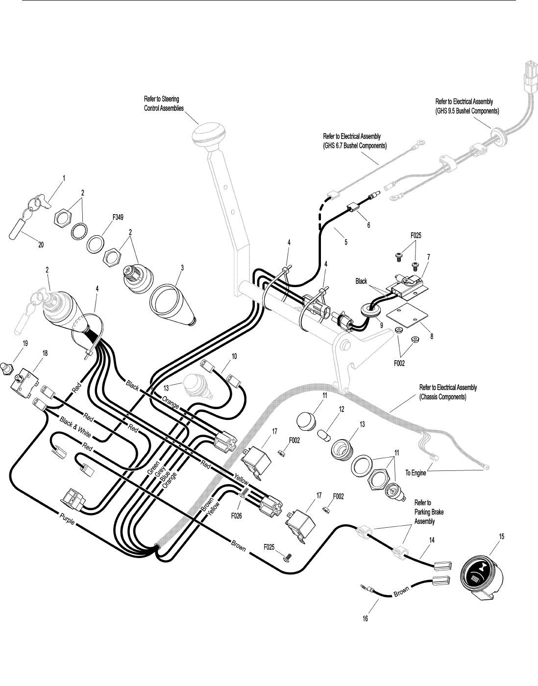
ELECTRICAL ASSEMBLIES (BODY COMPONENTS)
Electrical Assemblies (Body Components)
1 8960-2 Ignition Key (1 Set) 1
2 8960-21 Ignition Switch (with Keys) 1
(Includes Items # 1, 20 & F349)
3 5940-3 Ignition Switch Cover 1
4 5975-3 Cable Tie (50# x 7") 3
5 5983 Power Lead Wire, Body 1
6 5975-5 Wire Clip, Self-Mount 1
7 5941-5 Safety Switch 1
8 7203-6 Riser Plate 1
9 5977-6 Grommet 1
10 6940-10 Jumper Wire 1
11 8996-4 Red Indicator Lens 1
(Includes Item # 12)
12 8996-3 Indicator Bulb *
(Replacement for P/N 8996)
13 8996 Oil Pressure Light Assembly 1
(Includes Items # 11 & 12)
14 5991-1 Hourmeter Power Lead Wire 1
15 8990 Hourmeter 1
16 5991-2 Hourmeter Ground Wire 1
17 6941 Relay Switch (30/40 Amp) 2
18 7941-1 Circuit Breaker (5 Amp) 1
(Includes Item # 19)
19 7941-3 Boot, Circuit Breaker 1
20 7854 Key Tip Protector 1
Fasteners
F002 10-24 Keps Nut 4
F025 10-24 x 3/8 PPHMS 3
F026 10-24 x 1/2 PPHMS 1
F349 Washer .835 ID 1.122 OD, SS 1
*Service Part Only
NOTE: Refer to ELECTRICAL CONNECTORS, Page 40 for iden-
tification of all Electrical Wiring Service Parts.
35
Effective Date 12-01-00 Use only genuine Walker® replacement parts.
ELECTRICAL ASSEMBLIES (BODY COMPONENTS)

36
ITEM PART DESCRIP TION NO.
NO. NO. REQ’D ITEM PART DESCRIP TION NO.
NO. NO. REQ’D
Use only genuine Walker® replacement parts. Effective Date 12-01-00
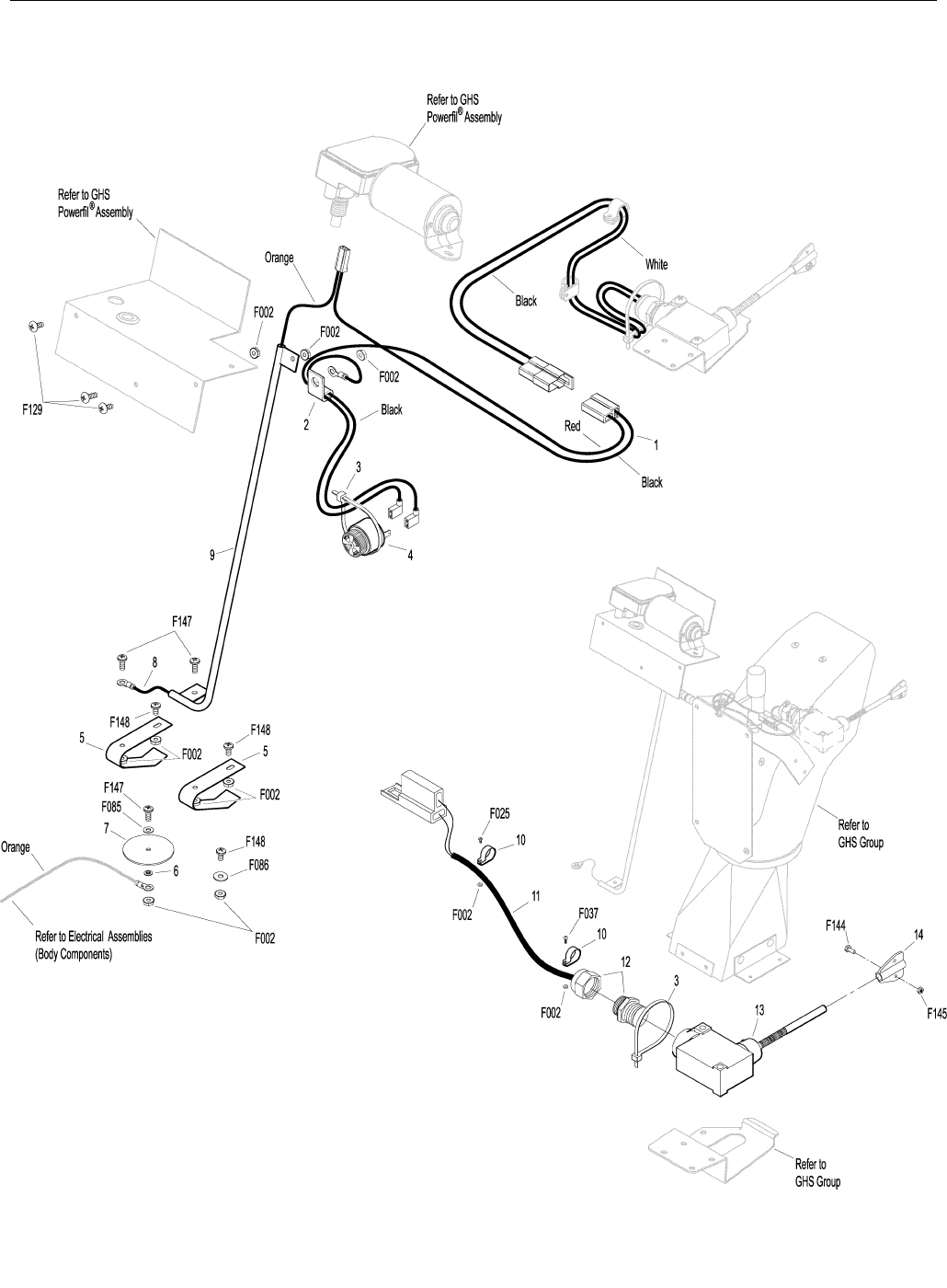
ELECTRICAL ASSEMBLIES (GHS 6.7 BUSHEL COMPONENTS)
Horn & Powerfil® Wiring Assemblies
1 5599 Pigtail Wire Set, Horn 1
2 5857 Wire Clamp (1/8 J-Clip) 1
3 5975-3 Cable Tie (50# x 7") 2
4 5536-2 Horn, Full Signal *
5 5984 Electric Contact Spring 2
6 5982-2 Insulator Bushing, Plastic 1
7 5982-1 Insulator Washer, Plastic (2") 1
8 5985-2 Power Lead Wire, Catcher 1
9 5988-1 Conduit Assembly, Powerfil® Wiring 1
5988-4 Powerfil® Tube & Wire Assembly *
(Includes Item # 8)
Grass-Pak® Switch Assembly
10 5833 Cable Clamp (1/4) 2
11 5980-3 Wire, Grass-Pak® Switch 1
12 5592-11 Liquid Tight Plug 1
13 5592-10 Grass-Pak® Switch Module 1
5592-4 Grass-Pak® Switch Assembly *
(Includes Items # 3 & 10-14) 1
14 5594-5 Vane Assembly, Grass-Pak® Switch 1
(Includes Items # F144 & F145) 1
Fasteners
F002 10-24 Keps Nut 11
F025 10-24 x 3/8 PPHMS 1
F037 10-24 x 5/8 PTH Screw 1
F085 3/16 Rivet Backup Washer 1
F086 #10 SAE Washer 1
F129 10-24 x 1/2 PTHMS 3
F144 4-40 x 1/4 PPHMS 1
F145 4-40 Keps Nut 1
F147 10-24 x 1/2 PPHMS SS 3
F148 10-24 x 3/8 PPHMS SS 3
*Service Part Only
NOTE: Refer to ELECTRICAL CONNECTORS, Page 40 for iden-
tification of all Electrical Wiring Service Parts.
37
Effective Date 12-01-00 Use only genuine Walker® replacement parts.
ELECTRICAL ASSEMBLIES (GHS 6.7 BUSHEL COMPONENTS)

38
ITEM PART DESCRIP TION NO.
NO. NO. REQ’D ITEM PART DESCRIP TION NO.
NO. NO. REQ’D
Use only genuine Walker® replacement parts. Effective Date 12-01-00
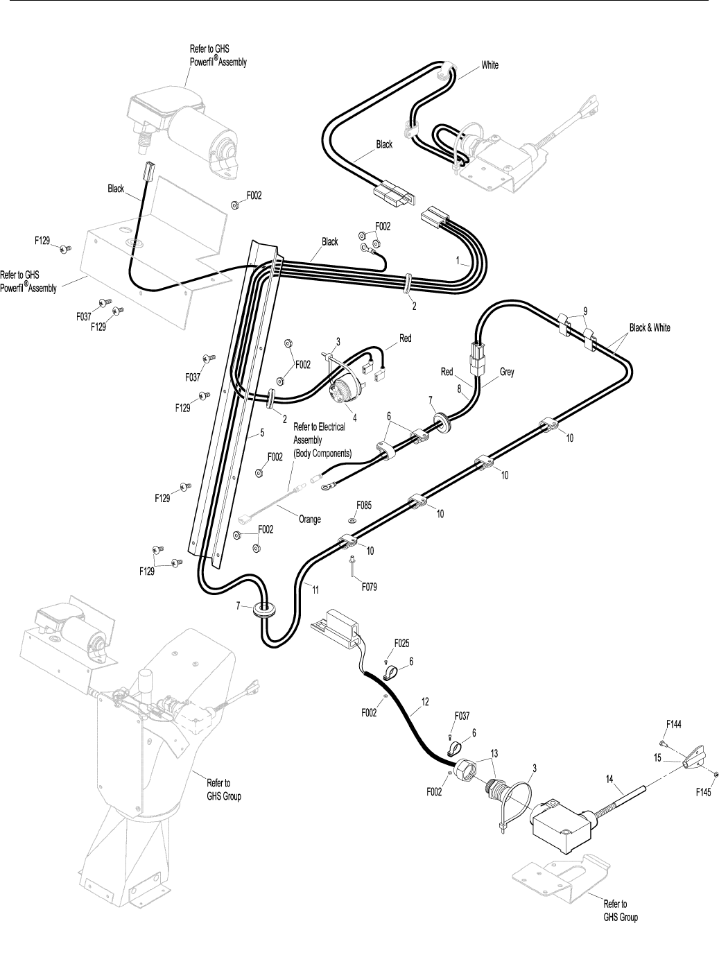
ELECTRICAL ASSEMBLIES (GHS 9.5 BUSHEL COMPONENTS)
Horn & Harness Channel Assemblies
1 5599 Pigtail Wire Set, Horn 1
2 5976 Grommet (3/8 ID x 11/16 OD) 2
3 5975-3 Cable Tie (50# x 7") 2
4 5536-2 Horn, Full Signal *
5 8117 9.5 Wire Harness Channel 1
Harness & Grass-Pak® Switch Assemblies
6 5833 Cable Clamp (1/4) 4
7 5977-2 Grommet, Cut (1/8 x 3/8) 2
8 8950-1 Extension Wire 9.5 Catcher 1
9 7835 Frame Clip 2
10 7834 Nylon Clamp 4
11 8950 Wire Harness, 9.5 Catcher 1
12 5980-3 Wire, Grass-Pak® Switch 1
13 5592-11 Liquid Tight Plug 1
14 5592-10 Grass-Pak® Switch Module 1
5592-4 Grass-Pak® Switch Assembly *
(Includes Items # 3, 6 & 12-15) 1
15 5594-5 Vane Assembly, Grass-Pak® Switch 1
(Includes Items # F144 & F145) 1
Fasteners
F002 10-24 Keps Nut 10
F025 10-24 x 3/8 PPHMS 1
F037 10-24 x 5/8 PTH Screw 3
F079 A/A66D Aluminum Pop Rivet 4
F085 3/16 Rivet Backup Washer 4
F129 10-24 x 1/2 PTHMS 6
F144 4-40 x 1/4 PPHMS 1
F145 4-40 Keps Nut 1
*Service Part Only
NOTE: Refer to ELECTRICAL CONNECTORS, Page 40 for iden-
tification of all Electrical Wiring Service Parts.
39
Effective Date 12-01-00 Use only genuine Walker® replacement parts.
ELECTRICAL ASSEMBLIES (GHS 9.5 BUSHEL COMPONENTS)

40
ITEM PART DESCRIP TION NO.
NO. NO. REQ’D ITEM PART DESCRIP TION NO.
NO. NO. REQ’D
Use only genuine Walker® replacement parts. Effective Date 12-01-00
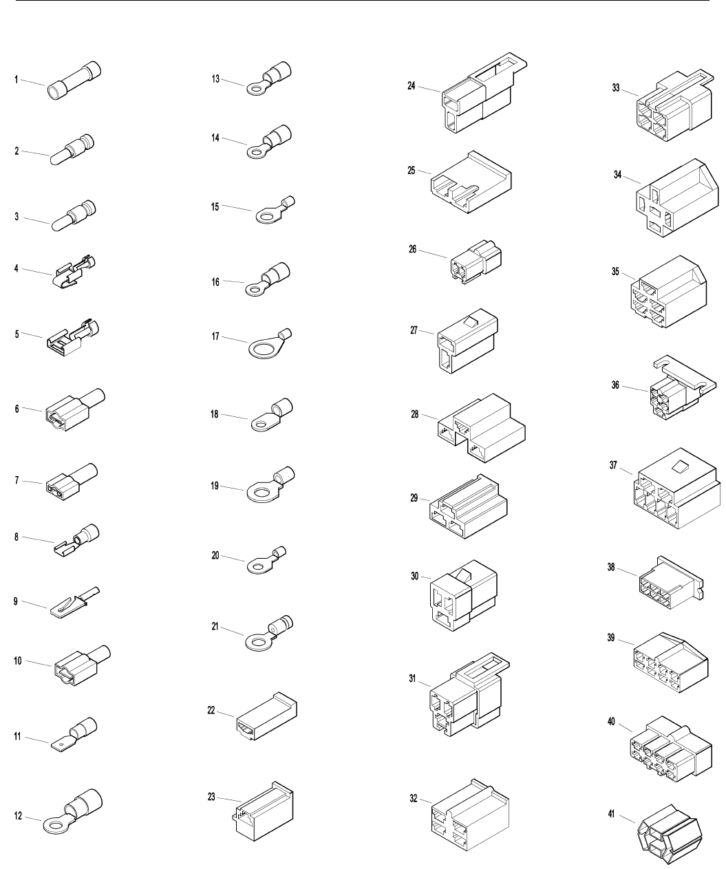
ELECTRICAL CONNECTORS
Electrical Wiring Service Parts
1 5996-1 16-14 GA Butt Conn. *
2 5996-4 16-14 GA Bullet Conn., Male *
3 5996-5 16-14 GA Bullet Conn., Female *
4 5940-4 16-14 GA Spg. Loaded Term., Female *
5 5940-7 Brass Wire Clip, Female *
6 5996 1/4 x 16-14 GA QKS Term., Female *
7 5996-2 3/16 x 22-18 GA QKS Term., Female *
8 7996 16-14 GA QKS Term., .187 (Female) *
9 5940-5 16-14 GA Spg. Loaded Term., Male *
10 5996-0 1/4 x 22-18 GA QKS Term., Male *
11 7996-1 1/4 x 16-14 GA QKS Term., Male *
12 5996-8 6 GA Ring Lug (5/16) *
13 5996-9 22-18 GA Ring Term., #10 *
14 5996-10 16-14 GA Ring Term. (5/16) *
15 5996-12 12-10 GA Ring Term. (5/16) *
16 5996-13 16-14 GA Ring Term., #10 *
17 5996-15 12-10 GA Ring Term. (1/2) *
18 5996-16 6 GA Ring Terminal (1/4) *
19 5996-17 16-14 GA Ring Term. (1/4) *
20 5996-20 12-10 GA Ring Term. (1/4) *
21 5996-21 12-10 GA Ring Term., #10 *
22 7942-4 Single Connector, Male *
23 8942 2-Way Connector, Male *
24 7942-1 2-Way Locking Connector, Female *
25 7942-2 2-Way Connector, Male *
26 7942-3 2-Way Connector, Female *
27 7942-10 2-Way Locking Connector, Male *
28 5940-8 3-Way Connector, Male *
29 7942-9 3-Way Connector, Male *
30 8944 3-Way Locking Connector, Male *
31 8944-1 3-Way Locking Connector, Female *
32 7942-11 4-Way Connector, Male *
33 7942-12 4-Way Connector, Female *
34 7942-5 5-Way Connector, Male *
35 5940-2 5-Way Connector, Male *
36 8942-1 5-Way Connector, Female *
37 7942-6 6-Way Connector, Male *
38 7942-7 6-Way Connector, Male *
39 7942-8 8-Way Connector, Male *
40 8942-2 8-Way Connector, Female *
41 8942-3 5-Way Connector, Male *
*Service Part Only
NOTE: Not all Electrical Connectors are used with all assemblies.
NOTE: Refer to ELECTRICAL ASSEMBLIES, Pages 32-39 for
locations of Wiring Harness, Electrical Components and of
all Electrical Wiring Service Parts.
Effective Date 12-01-00 Use only genuine Walker® replacement parts.
41
ELECTRICAL CONNECTORS

42
ITEM PART DESCRIP TION NO.
NO. NO. REQ’D ITEM PART DESCRIP TION NO.
NO. NO. REQ’D
Use only genuine Walker® replacement parts. Effective Date 12-01-00
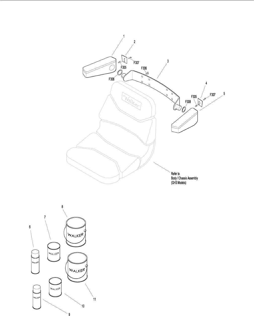
ARMREST KIT / TOUCH-UP PAINT
Kit 5885 Armrest Option / Kit
Includes Items # 1-5, fasteners listed and instructions. May be
ordered as a factory-installed option or as a kit for dealer installa-
tion. Contact your Walker dealer.
1 5886-1 Armrest, RH 1
2 5886-3 Cover Plate, RH 1
3 5887 Mounting Bracket 1
4 5886-4 Cover Plate, LH 1
5 5886-2 Armrest, LH 1
5888 Armrest Hardware Kit *
(Includes Items # F305, F306, F307 & F308)
Touch-Up Paint
6 5866 Touch-Up Paint, Yellow (12 oz. Aerosol)
7 5871 Touch-Up Paint, Yellow (1 qt.)
8 5871-1 Touch-Up Paint, Yellow (1 gal.)
9 5867 Touch-Up Paint, Grey (12 oz. Aerosol)
10 5873 Touch-Up Paint, Grey (1 qt.)
11 5873-1 Touch-Up Paint, Grey (1 gal.)
Fasteners
F305 1/4-20 x 3/8 SH Cap Screw 2
F306 3/8-16 x 3/4 Hex Bolt 4
F307 #10 x 5/8 PPHST Screw 2
F308 1-1/4 x 1-5/8 Wave Spring Washer 2
*Service Part Only
43
Effective Date 12-01-00 Use only genuine Walker® replacement parts.
ARMREST KIT / TOUCH-UP PAINT

44
ITEM PART DESCRIP TION NO.
NO. NO. REQ’D ITEM PART DESCRIP TION NO.
NO. NO. REQ’D
Use only genuine Walker® replacement parts. Effective Date 12-01-00
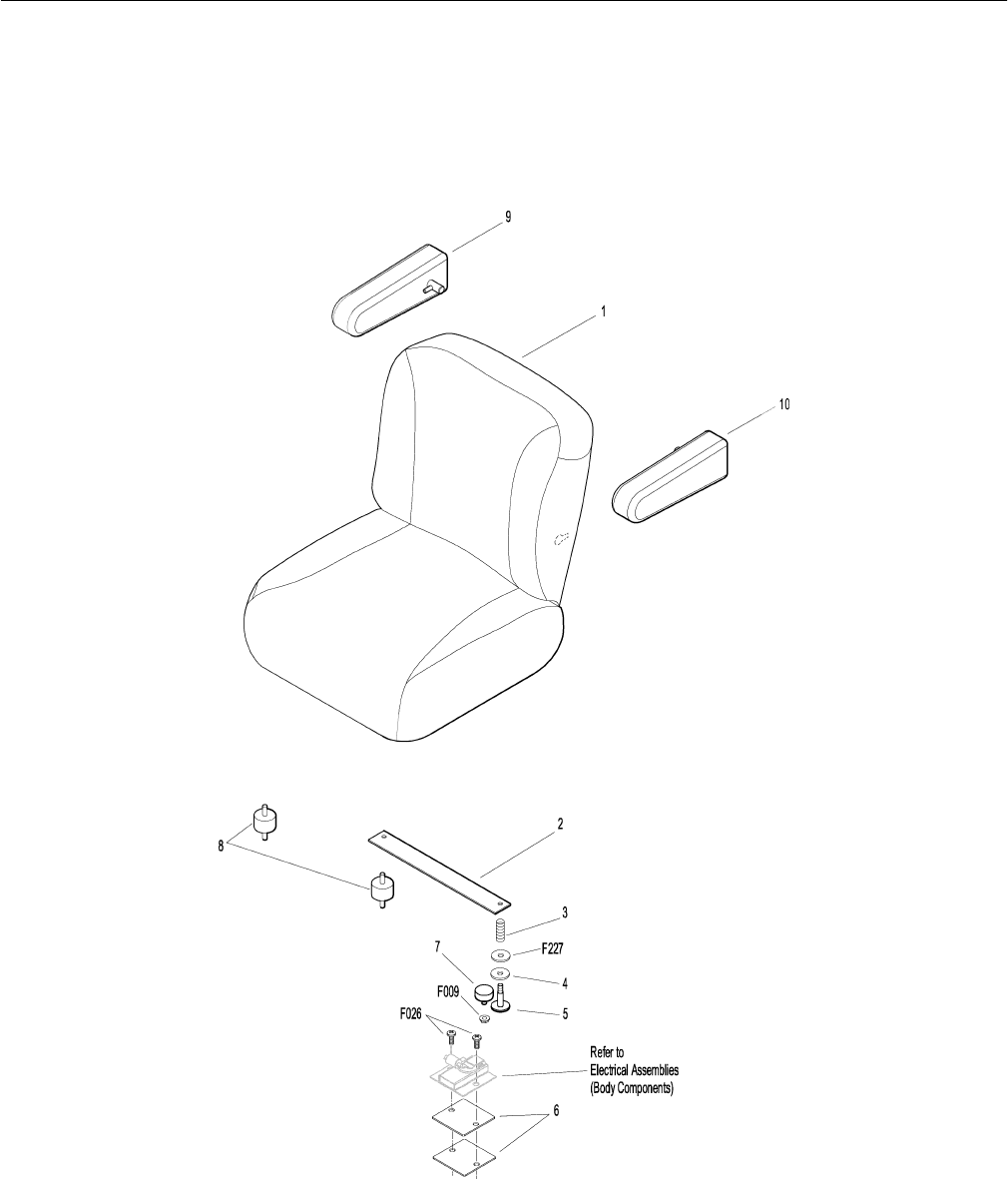
COMFORT SEAT / ARMREST KIT
Kit 6103-5 Comfort Seat Option / Kit (Grey)
Includes Items # 1, 6, fasteners listed (except as indicated; refer to
NOTE) and instructions. May be ordered as a factory-installed
option or as a kit for dealer installation. Contact your Walker
dealer.
1 6103-5 Comfort Seat 1
2 7203 Seat Spring Plate 1
3 7223 Compression Spring (1/2 x 1) 2
4 7845 Rubber Bumper (1.375 OD x .63) 2
5 7846 Rubber Washer (3/8 ID x 1-1/4 OD x 1/8) 2
6 7203-6 Riser Plate *
7 7204 Shoulder Bolt, Seat Mount 2
8 7440-5 Shock Mount (1.25 D x .75) 2
Kit 6103-15 Armrest Option / Kit
Includes Items # 9, 10 and instructions. Item # 9 is the Right side
armrest only. Item # 10 is the Left side armrest only. Sold only as a
complete set and may be ordered together as a factory-installed
option or as a kit for dealer installation. Contact your Walker
dealer.
9 NS Armrest, Right Side 1
10 NS Armrest, Left Side 1
Fasteners
F009 5/16 - 18 Whiz Locknut 2
F026 10-24 x 1/2 PPHMS 2
F227 3/8-1-1/4 x 1/8 Plastic Washer 2
*Only one Riser Plate is included with kit. One is reused from
Seat Switch. Refer to ELECTRICAL ASSEMBLIES (BODY
COMPONENTS), Page 34.
NOTE: Reuse Items # 3-8, F009 and F227 from Seat Assembly.
Refer to BODY / CHASSIS ASSEMBLY (GHS MODELS),
Page 4.
45
Effective Date 12-01-00 Use only genuine Walker® replacement parts.
COMFORT SEAT / ARMREST KIT

46
ITEM PART DESCRIP TION NO.
NO. NO. REQ’D ITEM PART DESCRIP TION NO.
NO. NO. REQ’D
Use only genuine Walker® replacement parts. Effective Date 12-01-00
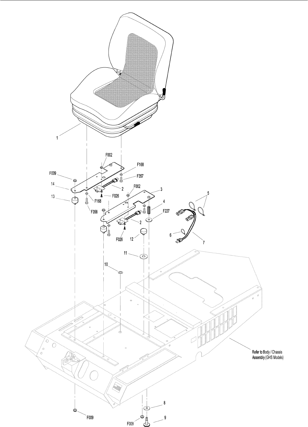
SUSPENSION SEAT KIT
Kit 6103-25 Suspension Seat Option / Kit
Includes Items # 1-3, 5-7, 11, 14, fasteners listed (except as indi-
cated; refer to NOTE) and instructions. May be ordered as a fac-
tory-installed option or as a kit for dealer installation. Contact your
Walker dealer.
1 6103-11 Suspension Seat 1
2 5941-5 Safety Switch (Normal Open) *
3 6103-33 Seat Mount Plate, LH 1
4 7223 Compression Spring 2
5 5975-3 Cable Tie (50# x 7") 2
6 5975-1 Cable Tie (18# x 3-3/4") 1
7 6103-23 Wire Harness, S/C/T Suspension Seat 1
8 7846 Rubber Washer 3/8 x 1-1/4 x 1/8 2
9 7204 Shoulder Bolt, Seat Mount 2
10 5977-6 Grommet (1 x 1-1/4) 2
11 5841 Retainer Washer 2
12 7845 Rubber Bumper (1.375 x 0.63) 2
13 7440-5 Shock Mount (1.25 x 0.75) 2
14 6103-34 Seat Mount Plate, RH 1
Fasteners
F002 10-24 Keps Nut 4
F009 5/16-18 Whiz Locknut 6
F026 10-24 x 1/2 PPHMS 4
F168 5/16 Split Lock Washer 4
F227 3/8 x 1-1/4 x 1/8 Washer (Plastic) 2
F357 M8 x 16 Hex Bolt 2
F358 M8 x 25 Hex Bolt 2
*Only one Safety Switch is included with kit. One is reused
from Electrical Assembly. Refer to ELECTRICAL ASSEM-
BLIES (BODY COMPONENTS), Page 34.
NOTE: Reuse Items # 4, 8-10, 12, two (2) each of Items # F002,
F009 and F026, and Item # F227 from Seat Assembly.
Refer to BODY / CHASSIS ASSEMBLY (GHS MODELS),
Page 4.
47
Effective Date 12-01-00 Use only genuine Walker® replacement parts.
SUSPENSION SEAT KIT

48
ITEM PART DESCRIP TION NO.
NO. NO. REQ’D ITEM PART DESCRIP TION NO.
NO. NO. REQ’D
Use only genuine Walker® replacement parts. Effective Date 12-01-00
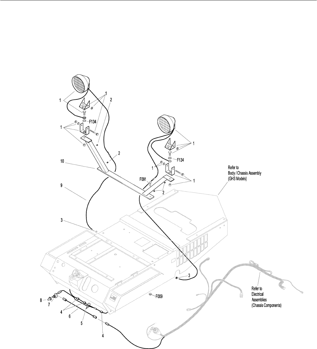
LIGHT KIT
Kit 5989 Light Option / Kit
Includes Items # 1-10, fasteners listed and instructions. May be
ordered as a factory-installed option or as a kit for dealer installa-
tion. Contact your Walker dealer.
1 5989-2 Light Assembly 2
(Includes Sealed Beam Lamp)
5989-6 Sealed Beam Lamp (Fits P/N 5989-2) *
2 7834-1 Half U-Wire Clip 4
3 5977-1 Grommet (1/8 x 3/8) 2
4 5975-5 Wire Clip, Self-Mount 3
5 5975-1 Cable Tie (18# x 3-3/4") 1
6 6940-10 Jumper Wire 1
7 5995 Toggle Switch (Off-On) 1
8 5995-2 Switch Boot 1
9 7995-3 Power Lead Wire Assembly (Lights) 1
(Includes Item # 5)
10 7992 Mount Bracket, Lights 1
Fasteners
F009 5/16-18 Whiz Locknut 2
F091 5/16-18 x 5/8 Hex Bolt 2
F134 AN960816L Washer 2
*Service Part Only
NOTE: Upon installation of kit, Item # 3 replaces P/N 5989-4
(Dome Plug, 3/8), Item # 5 replaces P/N 5989-5 (Dome
Plug, 7/16), and Item # F091 replaces P/N 5989-3 (Dome
Plug, 5/16). Dome Plugs are not shown here. Refer to
BODY / CHASSIS ASSEMBLY (GHS MODELS), Page 4.
NOTE: Refer to ELECTRICAL CONNECTORS, Page 40 for iden-
tification of all Electrical Wiring Service Parts.
49
Effective Date 12-01-00 Use only genuine Walker® replacement parts.
LIGHT KIT

50
ITEM PART DESCRIP TION NO.
NO. NO. REQ’D ITEM PART DESCRIP TION NO.
NO. NO. REQ’D
Use only genuine Walker® replacement parts. Effective Date 12-01-00
CASE-HARDENED BLOWER KIT
Kit 6542-15 Case Hardened Blower Option / Kit
Includes Items # 1-5, fasteners listed and instructions. May be
ordered as a factory-installed option or as a kit for dealer installa-
tion. Contact your Walker dealer.
1 5268 Bearing (3/4) Includes Locking Collar 2
2 NS Blower Housing (10") HT 1
3 6545-15 Blower Wheel (10") HT 1
4 6525-2 Faceplate (10" Blower) 1
5 6526 Intake Tube (6-1/2 x 2-1/2) 1
Fasteners
F004 1/4-20 Keps Nut 6
F074 1/4-20 x 3/8 Set Screw 2
51
Effective Date 12-01-00 Use only genuine Walker® replacement parts.
CASE-HARDENED BLOWER KIT

52
ITEM PART DESCRIP TION NO.
NO. NO. REQ’D ITEM PART DESCRIP TION NO.
NO. NO. REQ’D
Use only genuine Walker® replacement parts. Effective Date 12-01-00
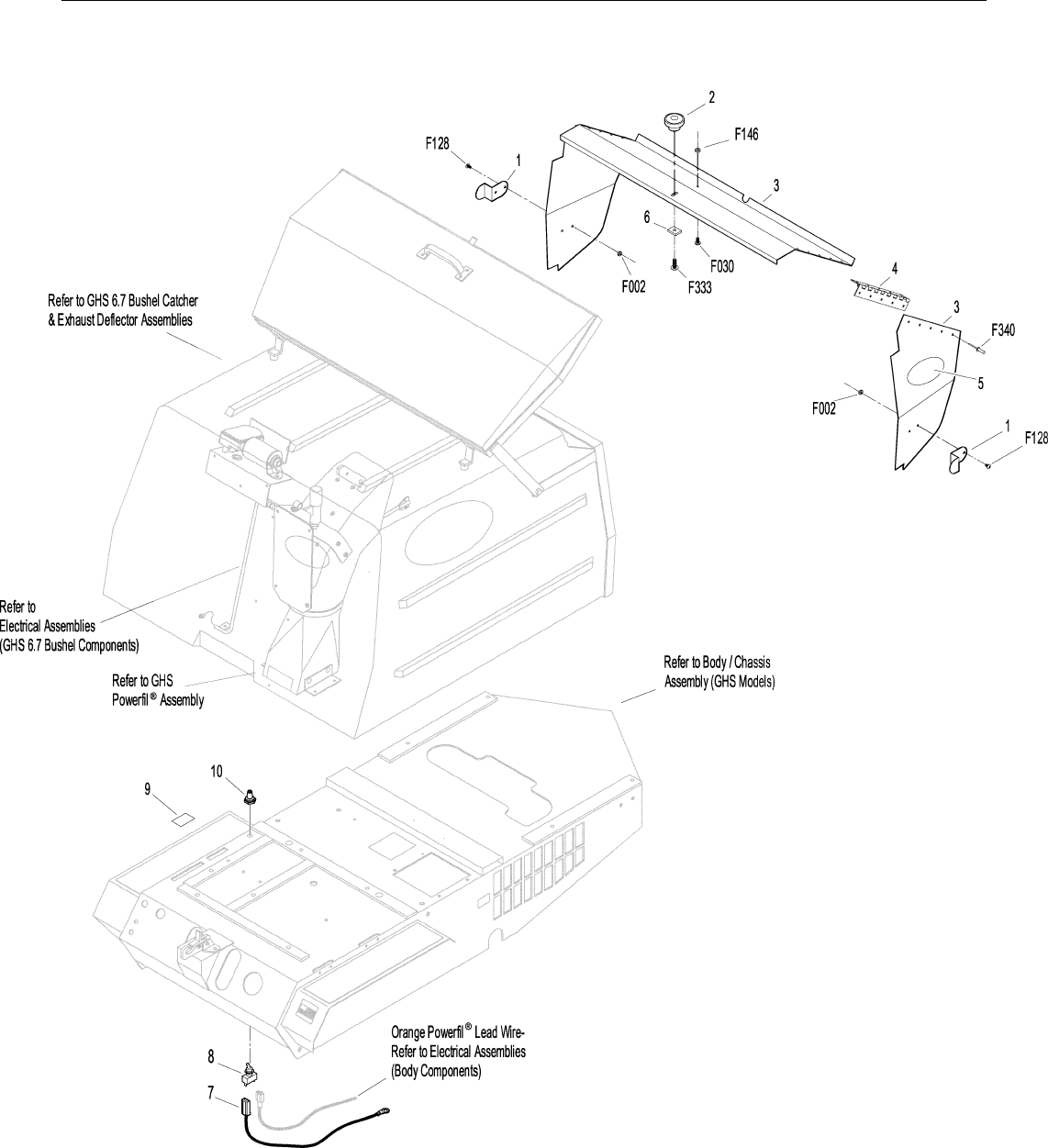
NO CATCH DEFLECTOR KIT (6.7 BUSHEL)
Kit 5500 No Catch Deflector Option / Kit (6.7 Bushel)
Includes Items # 1-10, fasteners listed and instructions. May be
ordered as a factory-installed option or as a kit for dealer installa-
tion. Contact your Walker dealer.
1 8500-5 Side Bracket 2
2 8787-2 Deflector Knob 1
3 5500 6.7 Deflector Assembly 1
(Includes Items # 4 & F340)
4 5726-10 Hinge, No-Catch (6.7 / 7.0) 2
5 8500-8 Decal, No Catch Deflector 1
6 8500-6 Spacer Lug 1
7 5500-8 Wire Assembly, 6.7 No Catch Deflector 1
8 5995 Toggle Switch (Off - On) 1
9 8500-9 Decal, Off - On 1
10 5995-2 Switch Boot 1
Fasteners
F002 10-24 Keps Nut 4
F030 1/4-20 x 1/2 PPH Bolt 1
F128 10-24 x 3/8 PTHMS 4
F146 1/4-20 Jam Nut 1
F333 1/4-20 x 3/4 PTHMS 1
F340 Rivet, Aluminum 20
NOTE: Refer to ELECTRICAL CONNECTORS, Page 40 for iden-
tification of all Electrical Wiring Service Parts.
53
Effective Date 12-01-00 Use only genuine Walker® replacement parts.
NO CATCH DEFLECTOR KIT (6.7 BUSHEL)

54
ITEM PART DESCRIPTION NO.
NO. NO. REQ’D ITEM PART DESCRIPTION NO.
NO. NO. REQ’D
Use only genuine Walker® replacement parts. Effective Date 12-01-00
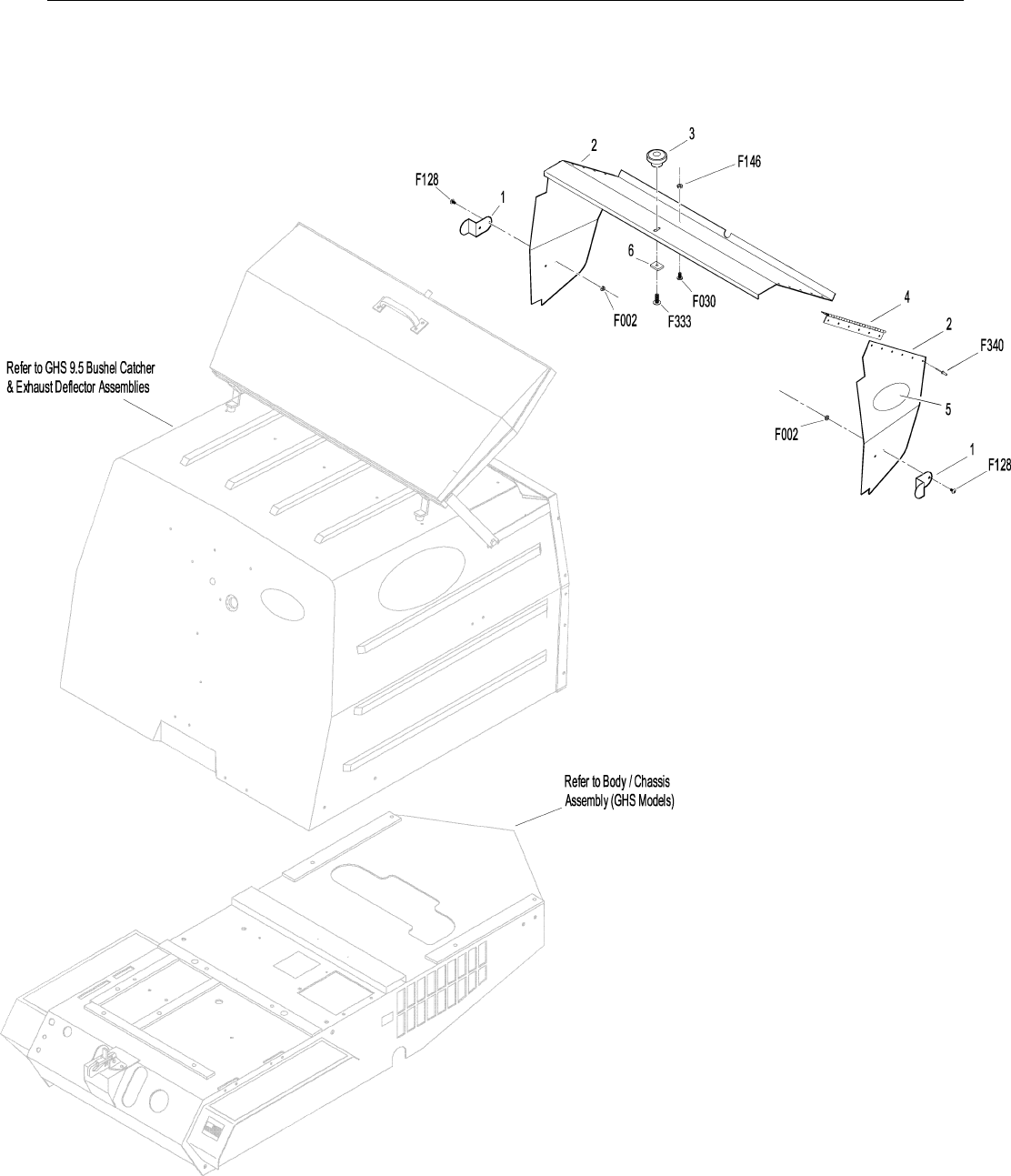
NO CATCH DEFLECTOR KIT (9.5 BUSHEL)
Kit 8500 No Catch Deflector Option / Kit (9.5 Bushel)
Includes Items # 1-6, fasteners listed and instructions. May be
ordered as a factory-installed option or as a kit for dealer installa-
tion. Contact your Walker dealer.
1 8500-5 Side Bracket 2
2 8500-1 Deflector Assembly (9.5) 1
(Includes Items # 4 & F340)
3 8787-2 Deflector Knob 1
4 7726-10 Hinge, No-Catch (9.5) 2
5 8500-8 Decal, No Catch Deflector 1
6 8500-6 Spacer Lug 1
Fasteners
F002 10-24 Keps Nut 4
F030 1/4-20 x 1/2 PPH Bolt 1
F128 10-24 x 3/8 PTHMS 4
F146 1/4-20 Jam Nut 1
F333 1/4-20 x 3/4 PTHMS 1
F340 Rivet, Aluminum 24
55
Effective Date 12-01-00 Use only genuine Walker® replacement parts.
NO CATCH DEFLECTOR KIT (9.5 BUSHEL)

56
ITEM PART DESCRIP TION NO.
NO. NO. REQ’D ITEM PART DESCRIP TION NO.
NO. NO. REQ’D
Use only genuine Walker® replacement parts. Effective Date 12-01-00
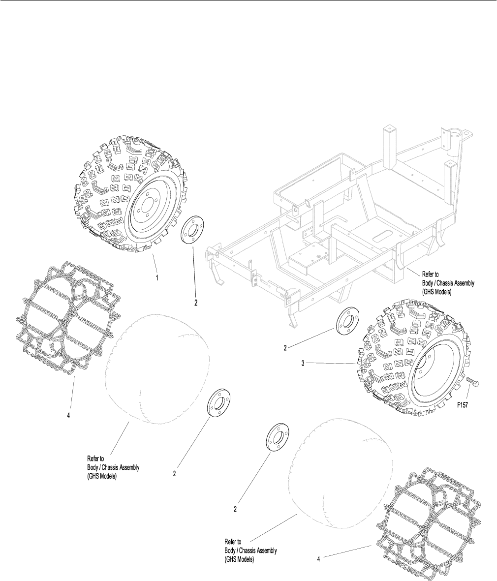
ALL-TERRAIN TIRE KIT & TIRE CHAIN SETS
Kit 8072 All-Terrain Tire Option / Kit
Includes Items # 1-3 and instructions. May be ordered as a factory
installed option, or as a kit for dealer installation. Contact your
Walker dealer.
1 8070 All-Terrain Wheel & Tire, RH 1
(18 x 11.00-10)
8070-1 AT Tire Only (18 x 11.00-10) *
8070-2 AT Wheel Only (10 x 8.5) *
2 8070-31 Wheel Spacer Plate (1/2) 2
3 8071 All-Terrain Wheel & Tire, LH 1
(18 x 11.00-10)
Optional Tire Chain Sets
Includes Items # 2 and 4. Tire Chain Sets are not for use on All-
Terrain Tires. Use only with tires listed at Item # 4. Refer also to
BODY / CHASSIS ASSEMBLY (GHS MODELS), Page 4.
4 5675-2 Tire Chain Set (18 x 8.50-8) 1
(Includes Item # 2)
(For use with Wide Wheel & Tire Assy)
5675 Tire Chain Set (18 x 6.50-8) 1
(Includes Item # 2)
(For use with Optional Narrow Drive Tires)
Fasteners
F157 1/2-20 x 1-1/4 Wheel Lug Bolt 8
*Service Part Only
NOTE: Reuse Item # F157 from Wheel & Tire Assembly. Refer to
BODY / CHASSIS ASSEMBLY (GHS MODELS), Page 4.
57
Effective Date 12-01-00 Use only genuine Walker® replacement parts.
ALL-TERRAIN TIRE KIT & TIRE CHAIN SETS

58
ITEM LOC ATION LUBRICATION NO.
NO. TYPE PLACES ITE M LOCATION LU BRICATION N O.
NO. TYPE PLACES
Use only genuine Walker® replacement parts. Effective Date 12-01-00
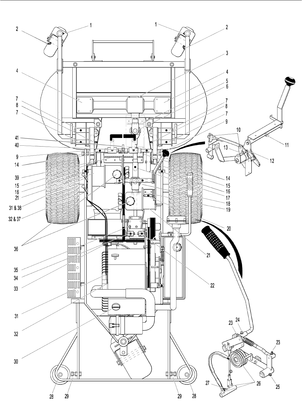
LUBRICATION POINTS
Lubrication Points
1 Deck Caster Wheel Fork Pivot Grease 2
2 Deck Caster Wheel Bearing Grease 2
3 Tee Gearbox, Deck Oil*1
4 Blade Drive Gearbox Oil*2
5 PTO Shaft Guard Hinge Oil 1
6 Universal Joint Shaft Assembly Grease** 1
7 Pivot Assembly, Tilt-Up Deck Grease 4
8 Deck Support Arm Socket Grease 2
9 Body Hinge Point Oil 2
10 FSC Actuator Rod Pivot Pins Oil 2
11 FSC Lever Pivot Grease 1
12 FSC Lever Fork Grease 1
(Grease Slide Area)
13 (FSC) Friction Body Pivot Grease 1
14 Steering Lever Pivot Grease 4
15 Deck Roller Wheel Oil 2
16 Deck Support Arm Pivot Grease 2
17 Deck-to-PTO Coupling Grease 1
(Grease Slide Area)
18 Universal Joint Tube Assembly Grease** 1
19 Universal Joint Quick Connect Grease 1
Spline (Grease Slide Area)
20 Parking Brake Lever Grease 1
21 Gear Axle Oil*** 2
22 Belt Tightener Pivot, Jackshaft Grease 1
Drive
23 Clutch Actuator Push Rod Grease 2
24 PTO Clutch Lever Pivot Grease 1
25 Belt Tightener Pivot PTO Clutch Grease 1
26 Brake Actuator Rod and Brake Oil*** 3
Band Pivot Pins (Clevis)
27 Brake Actuator Pivot Grease 1
28 Anti-Scuff Roller Wheel Oil 2
29 Catcher Hinge Point Oil 2
30 Engine Oil Oil*** 1
31 Choke Control Cable Ends Oil 2
32 Throttle Control Cable Ends Oil 2
33 Belt Tightener Pivot, Grease 1
Blower Drive (GHS Models Only)
34 Belt Tightener Pivot, Grease 1
Ground Drive
35 PTO Gearbox Dipstick Oil 1
36 Hydrostatic Drive Oil*** 2
37 Choke Control Pivot Oil 1
38 Throttle Control Pivot Oil 1
39 Discharge Chute Hinge Oil 1
40 Tilt-Up Latch Assembly Oil 1
41 Steering Lever Support Oil 1
*Gearboxes are permanently lubricated and sealed requiring
no scheduled lubrication. Oil level should be checked only
when an oil leak is noted.
** Grease every eight (8) hours.
*** See Owner’s Manual for procedure for checking and chang-
ing oil in Engine Crankcase, Hydrostatic Transmissions, and
Gear Axles.
NOTE: See Model MC Owner’s Manual (P/N 6000-1) for proper
lubrication intervals.
NOTE: DGHS42 Tilt-Up Deck is shown for reference. For other
Deck Lubrication Points, refer to Deck and Carrier Frame
Illustrated Parts Manual.
59
Effective Date 12-01-00 Use only genuine Walker® replacement parts.
LUBRICATION POINTS
60
Use only genuine Walker® replacement parts. Effective Date 12-01-00
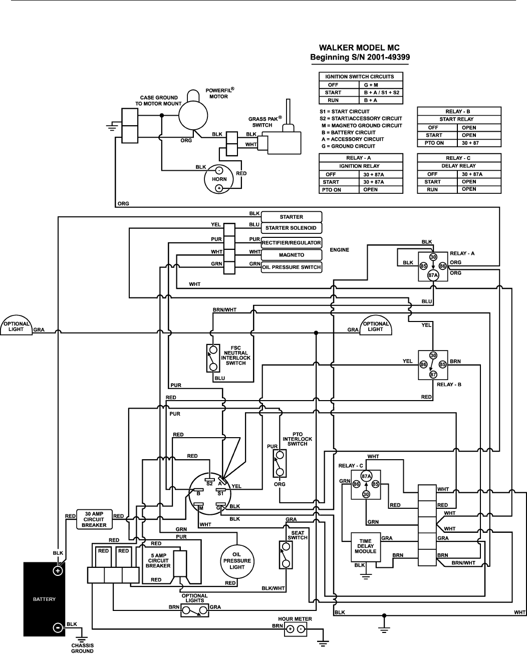
WIRING SCHEMATIC

61
LIMITED WARRANTY
FOR
WALKER
COMMERCIAL RIDER MOWER
1. WHAT THIS WARRANTY COVERS, AND FOR HOW LONG:
Walker Manufacturing company will, at its option, repair or replace, without charge, any part covered by this warranty
which is found to be defective in material and/or workmanship within one (1) year* after date of sale to the original retail
purchaser unless the product is used for rental purposes, in which case this warranty is limited to ninety (90) days. At
Walker's request, customer will make the defective part available for inspection by Walker and/or return the defective part
to Walker, transportation charges prepaid. All parts and components of the Walker Mower are covered by this warranty
except the following components which are warranted separately by their respective manufacturers:
Kohler Engine
Kubota Engine
Kawasaki Engine
Eaton Hydraulic Transmission
Peerless Gearboxes
Battery
Tires
The available warranties covering these items are furnished with each mower. Walker does not assume any warranty obli-
gation, liability or modification for these items, which are covered exclusively by the stated warranty of the respective man-
ufacturers noted above.
* An extended three (3) year warranty is offered on the Walker P/N 6200-7 Gear Axle Assembly.
2. WHAT THIS WARRANTY DOES NOT COVER:
A. This warranty does not cover defects caused by depreciation or damage caused by normal wear, accidents, improper
maintenance, improper use or abuse of the product, alterations, or failure to follow the instructions contained in the
Owner’s Manual for operation and maintenance.
B. The customer shall pay any charges for making service calls and/or for transporting the mower to and from the place
where the inspection and/or warranty work is performed.
3. HOW TO OBTAIN SERVICE UNDER THIS WARRANTY:
Warranty service can be arranged by contacting the dealer where you purchased the mower or by contacting Walker Man-
ufacturing Company, 5925 East Harmony Road, Ft. Collins, CO 80528. Proof of the date of purchase may be required to
verify warranty coverage.
4. WARRANTY LIMITATION:
A. THERE IS NO OTHER EXPRESS WARRANTY. ANY WARRANTY THAT MAY BE IMPLIED FROM THIS
PURCHASE INCLUDING MERCHANTABILITY AND FITNESS FOR A PARTICULAR PURPOSE IS HEREBY
LIMITED TO THE DURATION OF THIS WARRANTY AND TO THE EXTENT PERMITTED BY LAW ANY AND ALL
IMPLIED WARRANTIES ARE EXCLUDED. Some states do not allow limitations on how long an implied warranty
lasts, so the above limitations may not apply to you.
B. WALKER WILL NOT BE LIABLE FOR ANY INCIDENTAL, CONSEQUENTIAL, OR SPECIAL DAMAGES AND/OR
EXPENSES IN CONNECTION WITH THE PURCHASE OR USE OF THE MOWER. Some states do not allow the
exclusion or limitation of incidental or consequential damages, so the above limitation(s) or exclusion(s) may not
apply to you.
C. Only the warranty expressed in this limited warranty shall apply and no dealer, distributor, or individual is authorized
to amend, modify, or extend this warranty in any way. Accordingly, additional statements such as dealer advertising
or presentations, whether oral or written, do not constitute warranties by Walker, and should not be relied upon.
D. This warranty gives you specific legal rights, and you may also have other rights which vary from state to state.

WALKER MFG. CO. • 5925 E. HARMONY ROAD, FORT COLLINS, CO 80528 • (970) 221-5614
FORM NO. 030501 PRINTED IN USA ©2001 WALKER MFG. CO
www.walkermowers.com
