Walt Disney Parks and Resorts US TP-R1G2 TP-R1G2 User Manual

Walt Disney Parks and Resorts US., INC. TP-R1G2
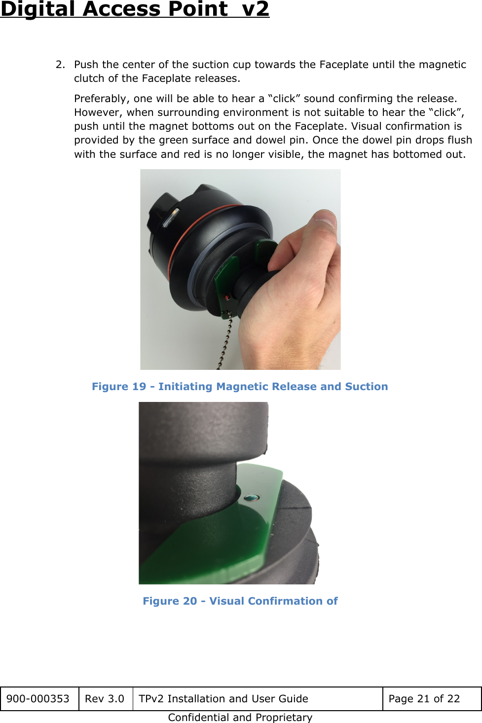
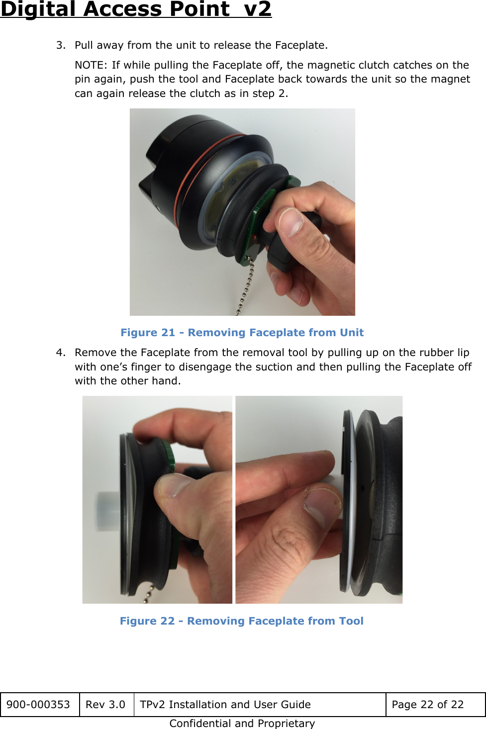
User Manual

Digital Access Point  v2  TPV2 INSTALLATION AND USER GUIDE      900-000353 Rev 3.0 TPv2 Installation and User Guide Page 1 of 22 Confidential and Proprietary
Digital Access Point  v2 Revision History  Rev Date Author Description 01 8/11/2016 Brian Piquette, Chris Burfeind Initial release 02 8/16/2016 Brian Piquette, Chris Burfeind Incremental updates and added detail 2.1 8/16/2016 Brian Piquette, Chris Burfeind Added Canadian approval callout and PoE Spec. 2.2 9/16/2016 Brian Piquette, Chris Burfeind Updated Hex wrench spec and added note for alternative step to plug cables in. Faceplate replacement section deleted. See 900-000356, TPv2 Service Guide. Fixed figure numbering. 2.3  Brian Piquette, Chris Burfeind Updated document number for Design Specification document  2.4 10/28/2016 BP/CB Updated section 2 with installation limitations. 3.0 03/03/2017 BP/CB Production Release: Updated Figure 2 to reflect changes to unit orientation and back housing. Updated section 5 with ESD grounding instructions. Added material list Added Faceplate installation and removal instructions.      900-000353 Rev 3.0 TPv2 Installation and User Guide Page 2 of 22 Confidential and Proprietary
Digital Access Point  v2 Table of Contents Table of Contents 1. Introduction 1.1 Purpose 1.2 Definitions 2. Safety Warnings 2.1 Trained Installation and Service Personnel Warning 2.2 Important Safety Instructions 2.3 Explosive Safety Warning 2.4 Lightning Warning 3. Regulatory Compliance 3.1 Federal Communications Commission (United States) 3.2 UL Certification 4. Specifications 4.1 Physical Connection Ports 4.2 HF RFID Capabilities 4.3 UHF RFID Capabilities 4.4 Proprietary 2.4GHz Radio Interface 4.5 BTLE Interface 4.6 Operating Conditions 4.7 Power 4.8 User Accessible Surfaces 4.9 Faceplate 5. Installation 5.1 Electrostatic Discharge Warning 5.2 Telecom Warning 5.3 Touch Point Installation Instructions 5.4 Faceplate Installation Instructions   900-000353 Rev 3.0 TPv2 Installation and User Guide Page 3 of 22 Confidential and Proprietary
Digital Access Point  v2   1. Introduction The Disney Touch Point version 2 (TPv2) Multi-Media Reader is part of a proprietary data                             acquisition system. It provides an HF RFID reader, UHF RFID reader, Bluetooth LE Host                           interface and a MagicBand 2.4GHz RF interface to read data from proprietary RFID and                           RF media. This RFID/RF tag data can be then sent over an Ethernet connection to a data                                 collection/concentration object. The TPv2 is designed to be mounted in several known                       stanchions which provide the final weatherproof enclosure for the product.  The TPv2 assembly is designed to be mounted in one of several different stanchion                           designs. Among the existing stanchion designs, there are multiple themed stanchions,                     and several kiosk installations. Figure 1 shows the TPv2 assembly that goes into the                           themed stanchion assemblies.    Figure 1 –TPv2 Assembly     900-000353 Rev 3.0 TPv2 Installation and User Guide Page 4 of 22 Confidential and Proprietary
Digital Access Point  v2 1.1 Purpose This document provides basic installation and user instructions for the Disney TPv2.  1.2 Definitions Term Definition RFID Radio Frequency Identification  OTS Off the shelf cULus (NRTL) Underwriters Laboratories  certified for U.S. and Canada (Nationally Recognized Testing Laboratory)     900-000353 Rev 3.0 TPv2 Installation and User Guide Page 5 of 22 Confidential and Proprietary
Digital Access Point  v2 2. Safety Warnings 2.1 Trained Installation and Service Personnel Warning Warning! Only those individuals that are trained and authorized by Walt Disney Parks                         and Resorts US., Inc. are permitted to install this equipment.   Continuing compliance with FCC requirements requires the installation instructions to                   be followed. No unauthorized modifications can be made to the equipment. Only the                         external antennas provided with this equipment may be used. The antennas approved                       for use with this product are as follows: ●Dipole: Linx P/N ANT-2.4-CW-HWR ●3x3 Passive Array: Disney Part number 300-001220.  Read and follow all warning notices and instructions marked on the product or included                           in the documentation. Before installing the product, read the rest of this document and                           follow specific product instructions. When installing, the placement of the device must also satisfy the following installation                         requirements: ●Placement must allow for easily disconnecting the power cord/adapter of the                     device from the AC wall-outlet. ●Keep the device away from excessive heat and humidity and keep the device                         free from vibration and dust. ●Installation must at all times conform to local regulations. ●Network Connections can be made with either Unshielded Twisted Pair (UTP) or                       Shielded Twisted Pair (STP) cabling.  2.2 Important Safety Instructions When using this device, basic safety precautions should always be followed to reduce                         the risk of fire, electric shock and injury to persons. Do not use this product near water. For example, do not use: ●near a bathtub ●near a wash bowl ●near a kitchen sink or laundry tub ●in a wet basement  900-000353 Rev 3.0 TPv2 Installation and User Guide Page 6 of 22 Confidential and Proprietary
Digital Access Point  v2 2.3 Explosive Safety Warning Warning! Do not operate this device near explosive devices, unshielded blasting caps                       or in an otherwise explosive environment unless the device has been approved for such                           use by qualified personnel. Warning! Do not disconnect the power or any other cabling in an explosive                         environment until such qualified personnel, trained specifically in explosive environment                   handling, have determined it is safe to do so. 2.4 Lightning Warning Warning! Do not connect or disconnect cables or otherwise work with the device                         hardware during periods of lightning activity. Avoid using this product during an electrical storm. There may be a remote risk of                             electric shock from lightning.     900-000353 Rev 3.0 TPv2 Installation and User Guide Page 7 of 22 Confidential and Proprietary
Digital Access Point  v2 3. Regulatory Compliance 3.1 Federal Communications Commission (United States) Regulatory Compliance Information This device complies with part 15 of the FCC Rules. Operation is subject to the following two conditions: (1) This device may not cause harmful interference, and (2) this device must accept any interference received, including interference that may cause undesired operation. Caution: Any changes or modifications not expressly approved by Walt Disney Parks and Resorts                         U.S. (WDPR) could void the user’s authority to operate this equipment. 3.2 UL Certification The TPv2 has been certified as a UL Recognized Component to the UL 60950-1 standard                             and CAN/CSA - C22.2 No 60950-1-07.     900-000353 Rev 3.0 TPv2 Installation and User Guide Page 8 of 22 Confidential and Proprietary
Digital Access Point  v2 4. Specifications The Disney TPv2 Reader has the following specifications: 4.1 Physical Connection Ports   Figure 2 –TPv2 Connections  ●Ethernet 10/100 RJ-45: 100m Max. cable length, Supports PoE+ PD (IEEE 802.3at-2009) ●USB-A HS port, Quantity =4: USB host ports for peripheral expansion. 500mA max current. ●DC Power Jack: Hirose Part Number RP34L-5R-3PD connector, See Document 604-0016-01 for the mate with connector detail and pinout. ●LRR TX SMA Jack  oThis is a female SMA connection for the transmit antenna. The transmit antenna must be installed at all times when the unit is powered up and transmitting. Transmitting without the antenna installed may damage the unit. o0 dBm max output, 2482MHz proprietary protocol  900-000353 Rev 3.0 TPv2 Installation and User Guide Page 9 of 22 Confidential and Proprietary
Digital Access Point  v2 oThis antenna must be of an approved or supplied type. Use of an unauthorized antenna is not allowed. The following 2 antennas are approved for use: ▪Linx Technology Part number ANT-2.4-CW-HWR-SMA, Gain = 3.2dBi ▪Disney PA3x3 Custom Antenna part Number 300-001220, Peak Gain = 12dBi  ●Relay Interface, Quantity=2:  oFemale TERM Block Phoenix Contact PN: 1803442 ▪J6 Pin1 = Relay1_C (pin 1 indicated with a red circle in image above) ▪J6 Pin2 = Relay1_NO ▪J6 Pin3 = Relay2_C ▪J6 Pin4 = Relay2_NO oCable side Male TERM Block Phoenix Contact PN: 1803594 oContact Form: SPST-NO oMax Voltage:  125VAC, 60VDC - Max oMax Current: 1A ●Optically Isolated Inputs, Quantity=2: oFemale TERM Block Phoenix Contact PN: 1803442 ▪J7 Pin1 = Input1+ (pin 1 indicated with a red circle in image above) ▪J7 Pin2 = Input1- ▪J7 Pin3 = Input2+ ▪J7 Pin4 = Input2-  oCable side Male TERM Block Phoenix Contact PN: 1803594 oInput Voltage: 24VDC oInput Current: 30mA  4.2 HF RFID Capabilities ●TX/RX: 13.56 MHz ●ISO 14443A, with support for proprietary security protocols  900-000353 Rev 3.0 TPv2 Installation and User Guide Page 10 of 22 Confidential and Proprietary
Digital Access Point  v2 4.3 UHF RFID Capabilities ●TX/RX: 902-926MHz ●EPCglobal UHF Class 1 Gen 2/ISO 18000-63 ●Output Power +10 to +20dBm 4.4 Proprietary 2.4GHz Radio Interface ●TX SMA Port: 2482MHz, 0dBm max ●RX: Internal RX Antenna 4.5 BTLE Interface ●RX/TX: Internal RX/TX antenna, 0dBm max 4.6 Operating Conditions Temperature: ●Operating: -10°C to 50°C ●Storage: -20°C to 60°C ●Operating Relative Humidity: 90% condensing/non-condensing ●Altitude: 8,000 ft @28°C (82.4°F) 4.7 Power DC Input: 24Vdc, 2A max NOTE: This product must be used with a DC power source that is cULus (NRTL) Listed, with an output rated 24VDC +/- 20% maximum, minimum 2A , Marked “LPS” or “Class 2”, output rated SELV, non-energy hazardous and suitable for connection to a standard power receptacle in the US and Canada. Power over Ethernet (IEEE, 802.3at compliant): PoE+ 48V dc, 500 mA              900-000353 Rev 3.0 TPv2 Installation and User Guide Page 11 of 22 Confidential and Proprietary
Digital Access Point  v2 4.8 User Accessible Surfaces        Figure 3 - User Accessible Surfaces  4.9 Faceplate Physical ●PN: 310-019266 (Figure 3) ●Plastic face material: PC+ABS TRILOY 210NH ●Rubber gasket material: SANTOPRENE 8211-55B100, SHORE 50A ●Dimensions Diameter: 82.9 mm (3.26 in) Paintable Surface Diameter:  82.8 mm (3.26 in) Paintable Surface Area:  5439.5 mm^2 (8.43 in^2)  Figure 4 - Removable Faceplate with Gasket  900-000353 Rev 3.0 TPv2 Installation and User Guide Page 12 of 22 Confidential and Proprietary
Digital Access Point  v2 Finish Requirements ●Only the identified off-white surfaces should have finish applied. Paint or finish on the gasket will compromise sealing confidence, while paint or finish on the TPv2 attachment feature will compromise ease of Faceplate installation/removal. ●RF performance with specific Faceplate finishes (paint, stickers, appliques etc) should be verified before deployment. 5. Installation 5.1 Electrostatic Discharge Warning  Warning! Wear an anti-static wrist strap or take other suitable measures to prevent                         electrostatic discharge when handling this equipment. 5.2 Telecom Warning Note: This unit is intended for local (intra-building) connections only and is not                       designed or evaluated for direct connections to the public telecommunications/cable                   distributions systems. Cable and Ethernet connections should be made in accordance to                       the National Electrical Code (NEC). For example, one of the following should be true*: - Cable runs are located in the same building as this unit. - Cable runs through air between buildings are less than 42m (140ft). - Cable runs between buildings are directly buried. - Cable runs between buildings are in underground conduit, where a continuous metallic                         cable shield or a continuous metallic conduit containing the cable is bonded to each                           building grounding electrode system. *These options are from the US National Electrical Code, Sections 800.10, 800.12, 800.13, 800.31, 800.32, 800.33, and 800.40.      900-000353 Rev 3.0 TPv2 Installation and User Guide Page 13 of 22 Confidential and Proprietary
Digital Access Point  v2 5.3 Touch Point Installation Instructions The TPv2 was designed to be installed in an aluminum mounting plate that is then installed in various stanchion/enclosure designs. For detailed mounting plate requirements refer to Drawing 310-019778, Stanchion Mounting Plate, Big Clocking Pin. For detailed enclosure/stanchion design rules, refer to Document 900-000358, TPv2 Design Specifications. Additional instructions to replace the Faceplate and Trim Ring of the TPv2 are provided in 900-000356, TPv2 Service Guide.  The images below show the TPv2 being installed into a generic mounting plate to demonstrate the steps involved with installation. The mounting plate is then installed in a stanchion that is a full enclosed, sealed enclosure for the TPv2.  NOTE: air volume minimums can be found in Document 900-000358, xTPv2 Design Specifications, and mounting plate requirements can be found in 310-019778, Stanchion Mounting Plate. Mounting plate MUST be metal, or undesirable thermal conditions may occur.  Materials ●(1) TPv2 unit ●DC Molykote 111 O-ring Lubricant ●Gloves ●(1) 5/16-18 X ¾” Bolt (irregular installations may require different length) ●M5 or 5/16 Hex Wrench ●Stanchion Grounding Wire ●5/16 Socket Driver ●Faceplate Removal Tool (if replacing Faceplate)    900-000353 Rev 3.0 TPv2 Installation and User Guide Page 14 of 22 Confidential and Proprietary
Digital Access Point  v2 To install the TPv2 Assembly: 1. Ensure that both O-rings on the Trim Ring are lubricated with DC Molykote 111 O-ring lubricant. Use proper o-ring applicator and gloves. Avoid getting lubricant on the front, guest accessible services.  Figure 5 – Lubricating the Trim Ring 2. Attach ESD grounding wire and lug to the Bridge using the #10-32 screw. Ensure the screw is tight enough so the lug does not move and electrical connection is made between the Bridge and the grounding wire. The grounding wire should be connected to earth ground via the stanchion.  Figure 6 – ESD Grounding Wire, Lug, and Screw      900-000353 Rev 3.0 TPv2 Installation and User Guide Page 15 of 22 Confidential and Proprietary
Digital Access Point  v2 3. Orient the Trim Ring pin to the groove in the mounting plate (12 o’clock). NOTE: Depending on the stanchion design, cables may need to be plugged into the device before it is seated in the mounting plate. Take care to not pinch cables when inserting the TPv2 into the stanchion. See step 5-6 for instructions on plugging cables in.    Figure 7 – Orienting the Trim Ring 4. Push the TPv2 in until the back of the Trim Ring flange is flush with the mounting plate. Ensure the Trim Ring pin seats in the groove on the mounting plate.  Figure 8 – Pushing the Subassembly     900-000353 Rev 3.0 TPv2 Installation and User Guide Page 16 of 22 Confidential and Proprietary
Digital Access Point  v2 5. Using an M5 or 5/16” Hex wrench, fasten the TPv2 unit to the mounting plate bridge (shown as brown below) with a 5/16-18 X ¾” bolt (irregular installations may require a different bolt length). Tighten so the Trim Ring flange remains flush against the front surface of the mounting plate.   Figure 9 – Securing Subassembly Against Mounting Plate Bracket 6. Plug in the Ethernet and power lead into the ports at the back of the TPv2. The arrow on the power lead is facing towards the back of the unit.      Figure 10 – Plugging in the Ethernet and Power Lead 7. Wait for the Ethernet indicator lights to show connection and activity by blinking. NOTE: It can take over a minute to connect, once the power is plugged in.   Figure 11 – Ethernet Indicator Lights 8. Upon completion of the physical installation, RF RSSI thresholds and RF output power settings may need to be adjusted through the network accessible control interface to fine tune the media read performance.  9. The installation is complete.  900-000353 Rev 3.0 TPv2 Installation and User Guide Page 17 of 22 Confidential and Proprietary
Digital Access Point  v2 5.4 Faceplate Installation Instructions  Figure 12 - Key Feature Definitions for Faceplate Installation To install a Faceplate: 1. Apply lubricant with DC Molykote 111 O-ring lubricant using the following steps: a. Apply a thin coat of lubricant around the whole outer sealing surface as shown.  Figure 13 - Lubricant Application on Wiper Seal   900-000353 Rev 3.0 TPv2 Installation and User Guide Page 18 of 22 Confidential and Proprietary
Digital Access Point  v2 b. Wipe around the sealing surface to only leave a slight wetting of the wiper seal as shown below.  Figure 14 -Wetting Wiper Seal 2. Center the magnetic bubble clutch on the pin and align the boss on the Faceplate with the indent on the Light Ring.  Figure 15 - Faceplate Alignment 3. Push the Faceplate to engage the pin into the bubble clutch. Ensure the boss of the Faceplate is seated in the indent of the Light Ring.  Figure 16 - Seating Faceplate  900-000353 Rev 3.0 TPv2 Installation and User Guide Page 19 of 22 Confidential and Proprietary
Digital Access Point  v2 4. Firmly push the center and along the circumference of the Faceplate to engage the Faceplate and its gasket’s radial seal are fully seated.  Figure 17 - Engaging Faceplate Seal 6. Wipe to remove any excess lubricant. 7. Faceplate installation complete. To remove a Faceplate: 1. Remove the cap from the removal tool and center the removal tool on the Faceplate. The magnet should encourage the centering.  Figure 18 - Aligning Removal Tool      900-000353 Rev 3.0 TPv2 Installation and User Guide Page 20 of 22 Confidential and Proprietary
Digital Access Point  v2  2. Push the center of the suction cup towards the Faceplate until the magnetic clutch of the Faceplate releases. Preferably, one will be able to hear a “click” sound confirming the release. However, when surrounding environment is not suitable to hear the “click”, push until the magnet bottoms out on the Faceplate. Visual confirmation is provided by the green surface and dowel pin. Once the dowel pin drops flush with the surface and red is no longer visible, the magnet has bottomed out.  Figure 19 - Initiating Magnetic Release and Suction  Figure 20 - Visual Confirmation of     900-000353 Rev 3.0 TPv2 Installation and User Guide Page 21 of 22 Confidential and Proprietary
Digital Access Point  v2 3. Pull away from the unit to release the Faceplate. NOTE: If while pulling the Faceplate off, the magnetic clutch catches on the pin again, push the tool and Faceplate back towards the unit so the magnet can again release the clutch as in step 2.  Figure 21 - Removing Faceplate from Unit   4. Remove the Faceplate from the removal tool by pulling up on the rubber lip with one’s finger to disengage the suction and then pulling the Faceplate off with the other hand.  Figure 22 - Removing Faceplate from Tool     900-000353 Rev 3.0 TPv2 Installation and User Guide Page 22 of 22 Confidential and Proprietary

Navigation menu