Watteam WTPB Cycling Power Meter, PowerBeat 1.0 User Manual
Watteam Ltd Cycling Power Meter, PowerBeat 1.0
UserManual.wiki
>
Watteam
>
WTPB User Manual
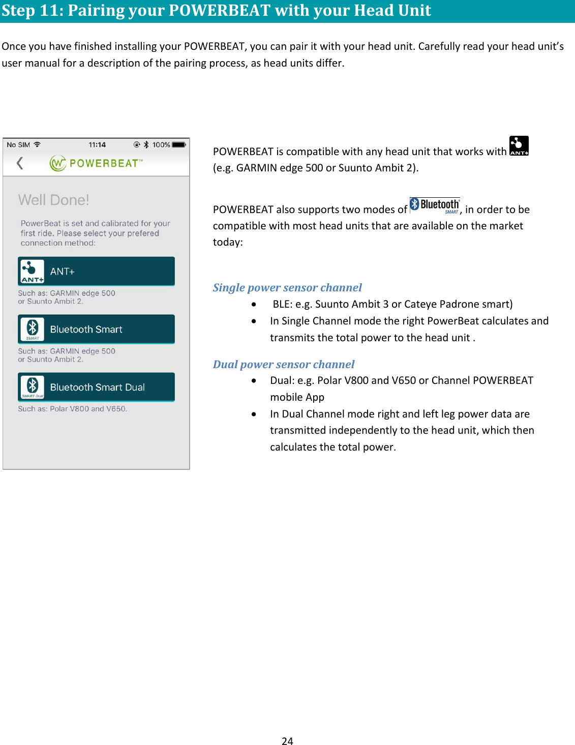
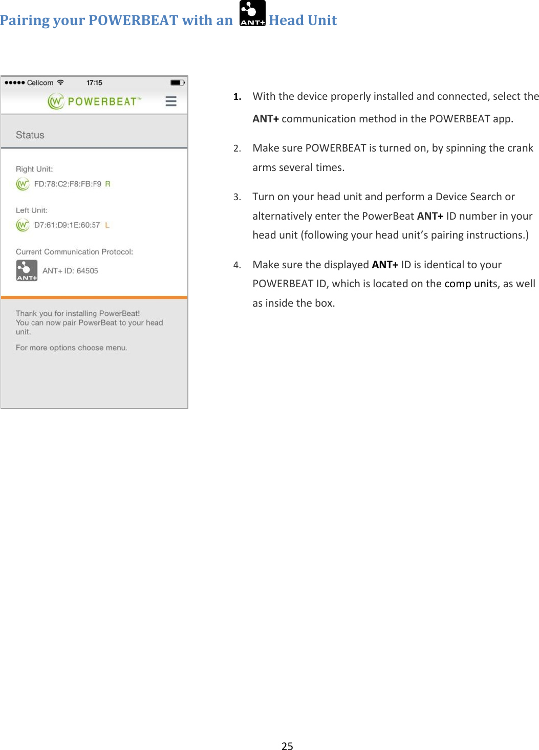
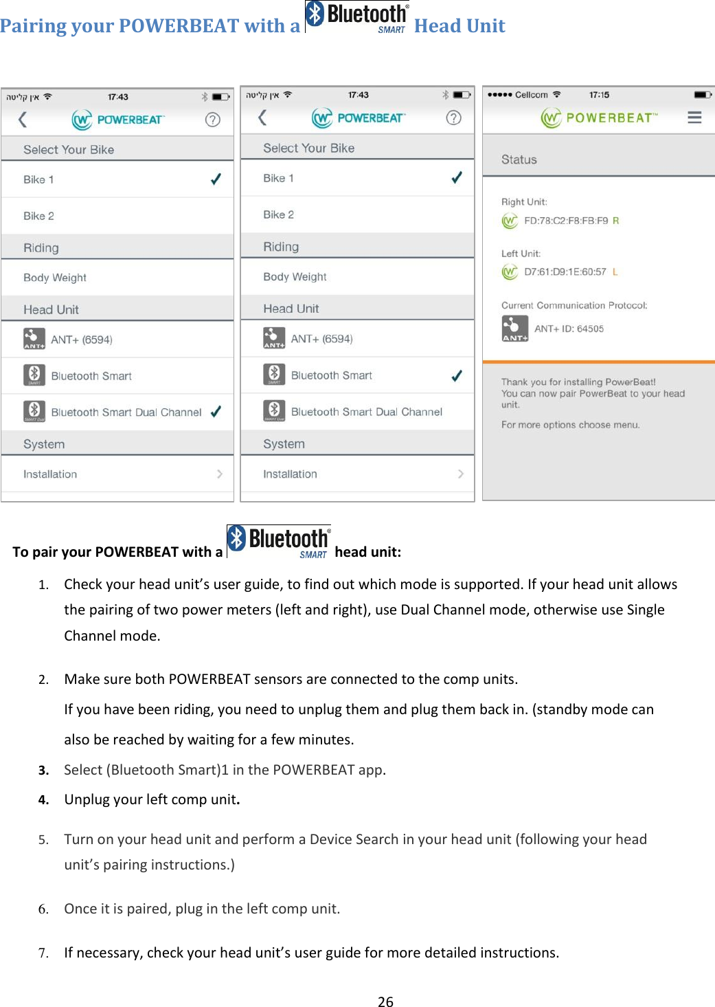
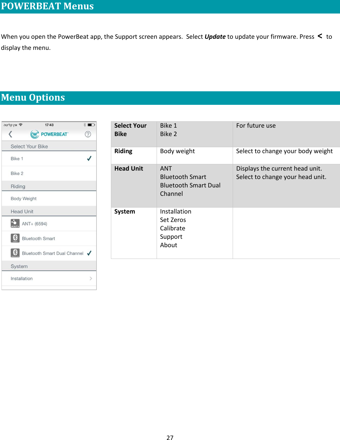
User Manual
Navigation menu
Upload a User Manual
Namespaces
Wiki Guide
HTML
PDF
Info
Views
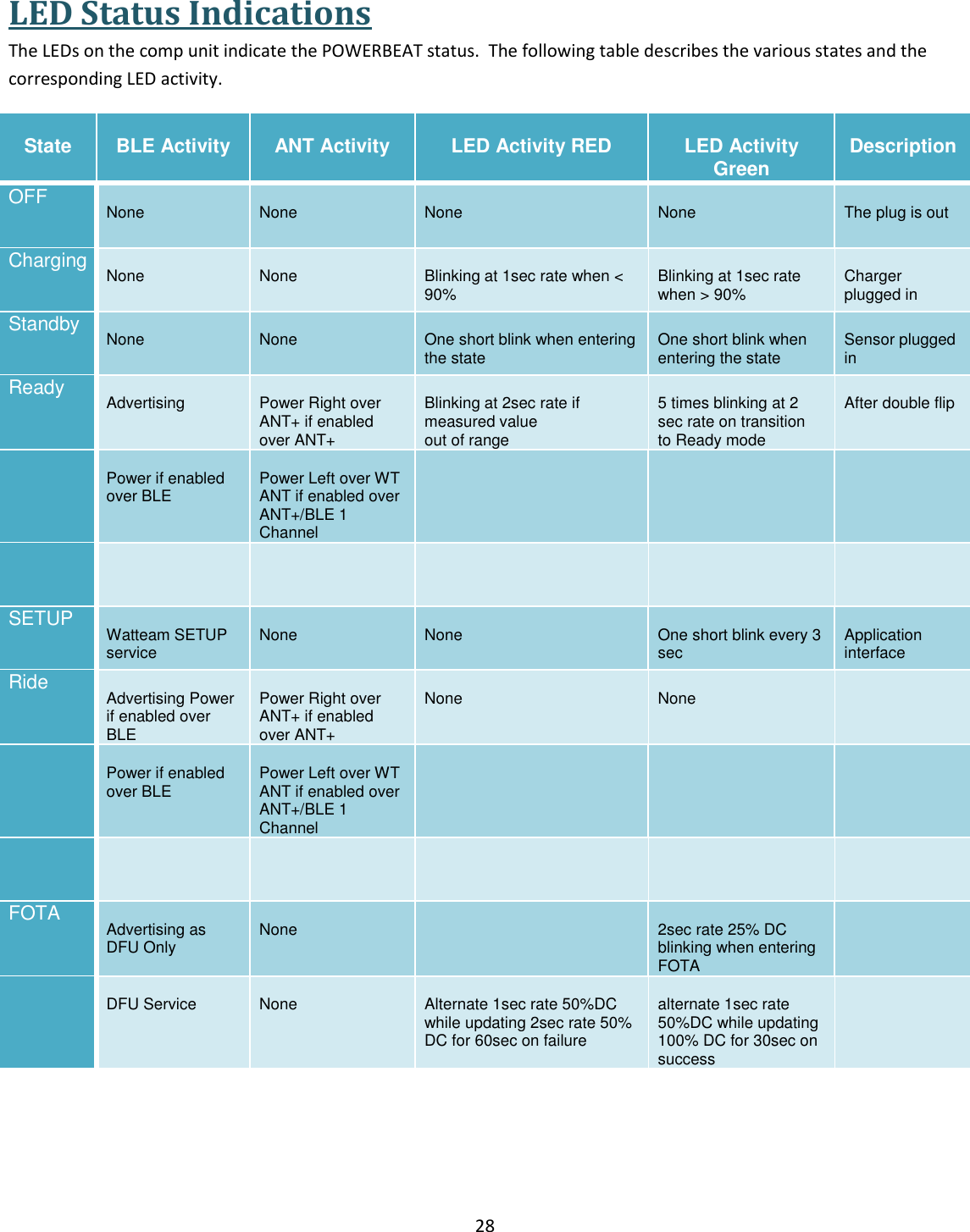
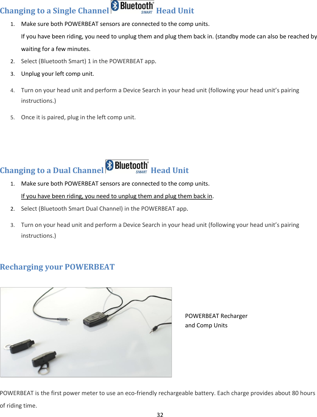
User Manual
Discussion / Help
Navigation