Watteam WTPB Cycling Power Meter, PowerBeat 1.0 User Manual
Watteam Ltd Cycling Power Meter, PowerBeat 1.0
Watteam >
User Manual


1
Contents
POWERBEAT Package Contents ..........................................................................................................3
POWERBEAT Data ..................................................................................................................................... 4
Installation ........................................................................................................................................4
Before Getting Started .............................................................................................................................. 5
Conventions .......................................................................................................................................... 5
Step 1: Downloading the POWERBEAT application .................................................................................. 6
Step 2: Accepting the end-user license agreement .................................................................................. 6
Step 3: Scanning the QR code (barcode) .................................................................................................. 7
Step 4: Registering your POWERBEAT ...................................................................................................... 8
Step 5: Entering crank details and body weight ....................................................................................... 9
Step 6: Removing the Left and Right Pedals ............................................................................................. 9
Removing the Left Pedal ....................................................................................................................... 9
Removing the Right Pedal ................................................................................................................... 10
Step 7: Gluing the Left and Right Sensors ............................................................................................... 10
Three Rules for Situating the Sensor in the Perfect Position .............................................................. 11
The Gluing Tool ................................................................................................................................... 12
Cleaning the Crank Arms ..................................................................................................................... 12
Attaching the Gluing Tool ................................................................................................................... 13
Gluing the Sensors .............................................................................................................................. 14
Step 8: Installing the Left and Right Comp Units .................................................................................... 15
Tools .................................................................................................................................................... 15
Installing the Left Comp Unit .............................................................................................................. 16
Installing the Right Comp Unit ............................................................................................................ 16
Connecting the Sensors to the Comp Units ........................................................................................ 17
Manual Scan ........................................................................................................................................ 19
Step 9: Zero Offset Calibration................................................................................................................ 19
Step 10: Calibration ................................................................................................................................. 19
Tools .................................................................................................................................................... 20
Preparing the Water Bags (Weights) .................................................................................................. 20
Calibrating the left and right crank ..................................................................................................... 21
Step 11: Pairing your POWERBEAT with your Head Unit ........................................................................ 24
Pairing your POWERBEAT with an Head Unit ............................................................................... 25

2
Pairing your POWERBEAT with a Head Unit ...................................................................... 26
POWERBEAT Menus ................................................................................................................................ 27
Menu Options ......................................................................................................................................... 27
LED Status Indications ...................................................................................................................... 28
Important Safety Information .......................................................................................................... 29
Troubleshooting .............................................................................................................................. 30
Maintenance ................................................................................................................................... 30
Mobile App Updates ............................................................................................................................... 30
Firmware Updates ................................................................................................................................... 31
Changing your POWERBEAT Communication Protocol .......................................................................... 31
Changing to an Head Unit ............................................................................................................ 31
Changing to a Single Channel Head Unit .......................................................................... 32
Changing to a Dual Channel Head Unit ............................................................................ 32
Recharging your POWERBEAT ............................................................................................................. 32
Removing the Sensors ......................................................................................................................... 33
Appendix A ...................................................................................................................................... 35
Warranty ................................................................................................................................................. 35
Warnings and Legal .................................................................................... Error! Bookmark not defined.
FCC Warning ............................................................................................... Error! Bookmark not defined.
3
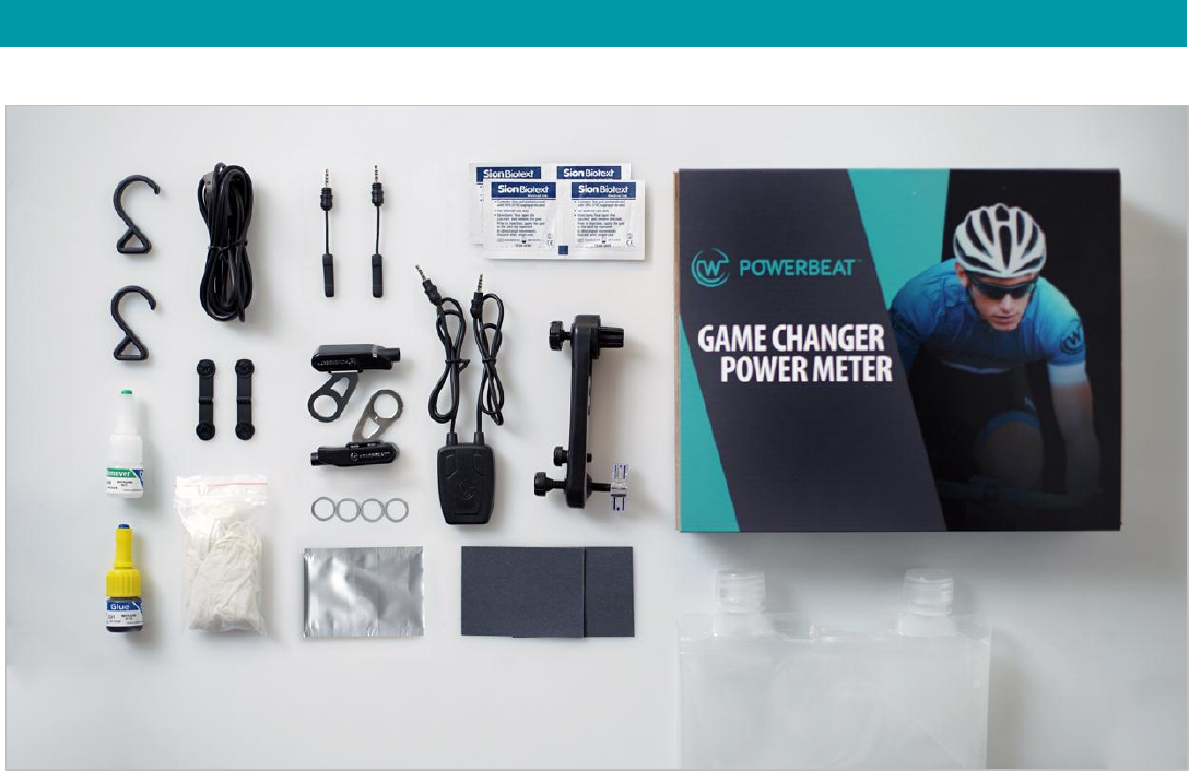
POWERBEAT Package Contents
The POWERBEAT package consists of the following:
2 Comp Units
2 sensors
1 Gluing tool
1 Charger with cable
1 User’s Manual
1 USB cable
2 adhesive rubber strips
4 washers (spacers)
4 alcohol pads
2 pieces of sandpaper
1 tube of glue
1 tube of glue remover
1 pair of protective rubber gloves
1 primer pad
2 hooks
2 water bags
4
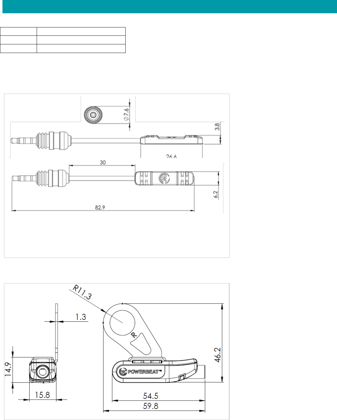
POWERBEAT Data
POWERBEAT Comp Unit Dimensions
POWERBEAT Sensor Dimensions
Weight
25 grams
IP
67
Humidity
5 to 95% non-condensing
5
Installation
Before Getting Started
Conventions
In this document the names of buttons on the application are written in bold italic, for example:
“Press Next ” means to press the Next button on the application.
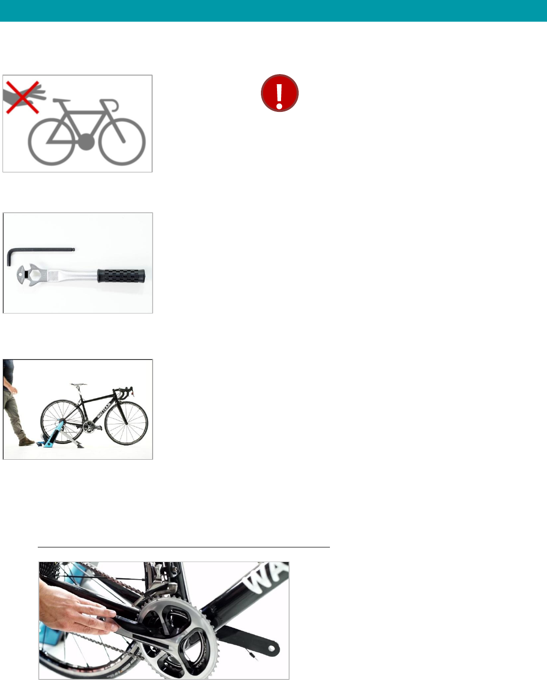
Once you begin
setup, you will not
be able to ride your
bike for the next 24
hours.
You will need a 6 or 8 mm Allen key or a 15
inch ratcheting wrench, depending on the
type of pedal on your bike.
Mount your bike to a trainer so it is steady throughout the
entire installation process. This is especially important when
you glue the sensors, attach the comp units and calibrate the
POWERBEAT.
Once you have installed the POWERBEAT application, it will
guide you through the installation process, step by step.
Most of the steps need
to be repeated on
both the left and right
sides of the bike.
Always start with the
left side.

6
POWERBEAT installation consists of the following steps:
1. Downloading the POWERBEAT application
2. Accepting the end-user license agreement (EULA)
3. Scanning the QR code (barcode)
4. Registering your POWERBEAT
5. Selecting crank type
6. Removing the left and right pedals
7. Gluing the left and right sensors, then waiting 24 hours for the glue to dry
8. Installing the left and right comp units
9. Zero Calibration
10. Calibration
11. Pairing your POWERBEAT with your head unit
Step 1: Downloading the POWERBEAT application
Step 2: Accepting the end-user license agreement
Download the WATTEAM
POWERBEAT application from
Google Play or the Apple store.
1. In the POWERBEAT app Welcome screen, follow the link
to the end-user license agreement and read it carefully.
2. Check Accept end-user license agreement and press
Next to display the Set Up screen.
7
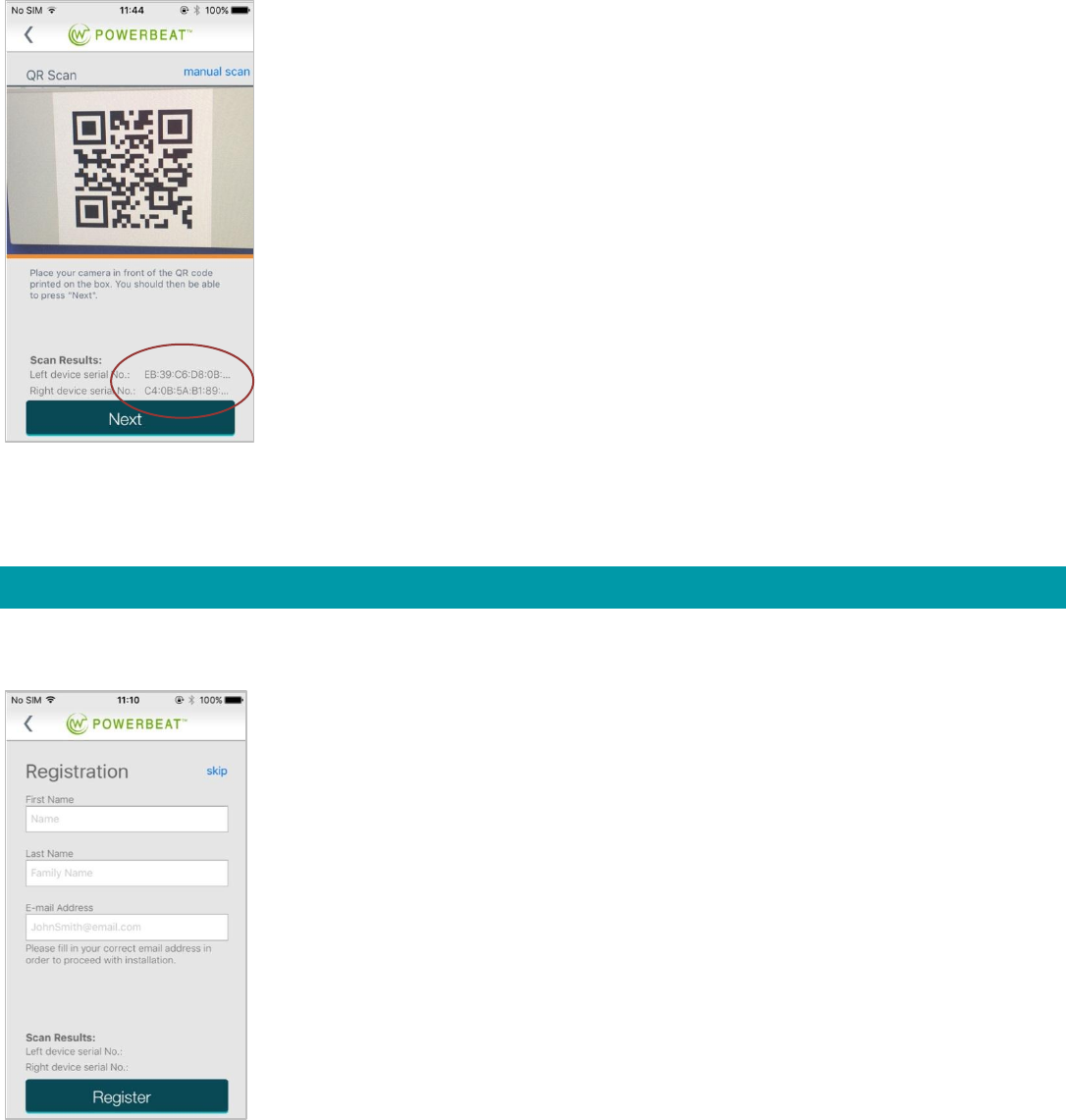
Step 3: Scanning the QR code (barcode)
The first stage of POWERBEAT installation is scanning the QR code.
NOTES:
The QR code is printed on the inside lid of the POWERBEAT box.
The iPhone has a barcode reader.
If your phone has an Android operating system, you will need to first download a barcode reader.
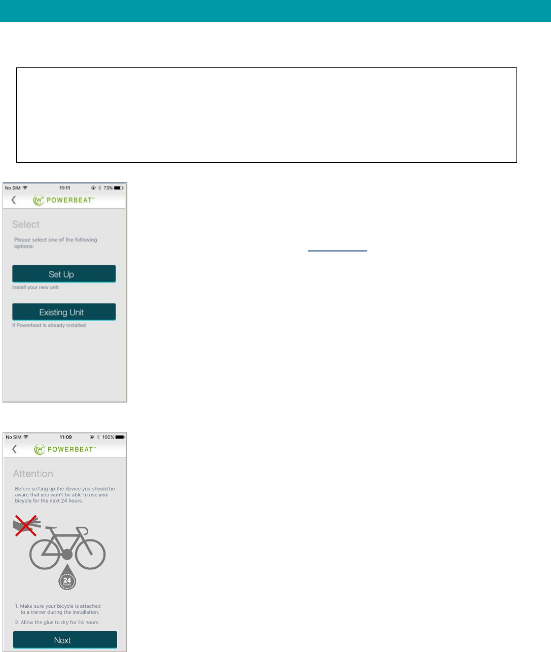
1. Press Set Up to scan the QR code.
(Or, if your PowerBeat is already installed and you
want to access it with a new smartphone, press
Existing Unit and proceed to 0Manual Scan.)
2. When the Attention screen
appears, press Next.
8
Step 4: Registering your POWERBEAT
Your POWERBEAT is now installed and ready to be paired with your head unit.
3. The camera in the smartphone is activated. When you aim it at
the QR code on the inside lid of the POWERBEAT box, it
recognizes the QR code and photographs it and the QR Scan
screen appears.
4. Make sure the QR codes displayed are the same as those on the
left and right comp units.
5. Press Next to display the Registration screen.
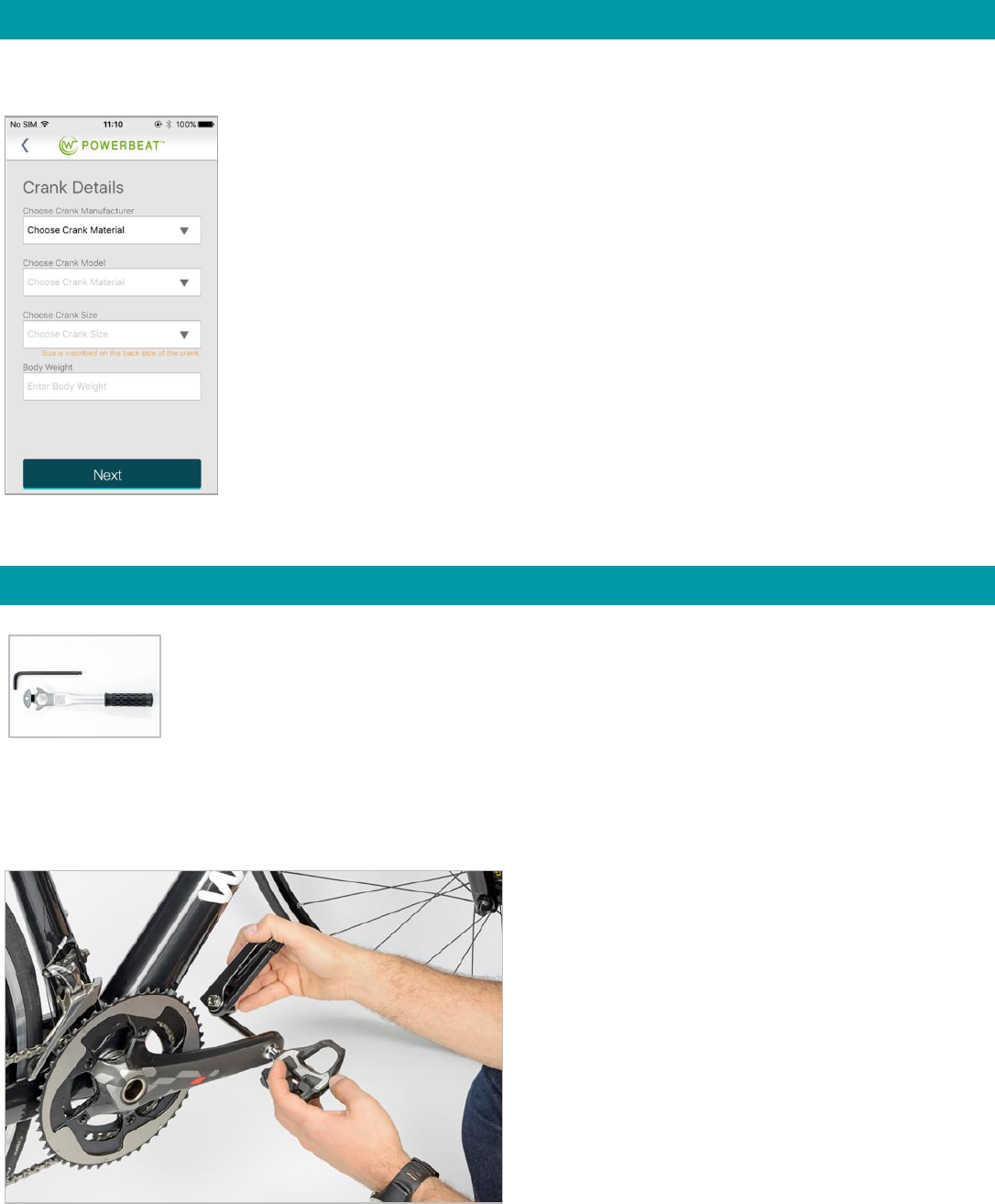
In the Registration screen enter your first
name, last name, and email address and press
Register.
Once you have registered your POWERBEAT
the Crank Details screen appears.
9
Step 5: Entering crank details and body weight
When the Crank Details screen appears, enter the following information in this order:
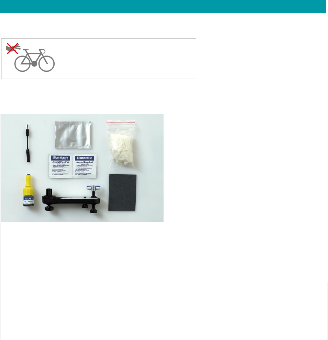
Step 6: Removing the Left and Right Pedals
Removing the Left Pedal
1. Crank manufacturer
2. Crank model
3. Crank size (printed on the inside of the
crank)
4. Your body weight
Press Next to display the Removing Pedals
screen.
Tools: Allen key or ratcheting wrench
1. With the left crank arm pointing
downwards towards the floor, insert the
appropriate Allen key or ratcheting
wrench into the back side of the pedal
spindle, holding the pedal down so it
doesn’t spin.
2. Turn the Allen key in a clockwise
direction until the pedal comes off.
10
Removing the Right Pedal
1. With the right crank arm pointing downwards towards the floor, remove the right pedal in the same way, but
turning the Allen key in a counter-clockwise direction.
2. Put the two pedals aside until tomorrow, when you will reattach them.
3. Press Next.
Step 7: Gluing the Left and Right Sensors
Note: The sensors have no right or left side, so you can glue either sensor to either crank arm.
To glue the two sensors you will need the following:
Once you have glued the sensors, you will need
to wait 24 hours for the glue to dry.
Included with your PowerBeat:
2 sensors
1 gluing tool
2 refillable water bags
1 charger with cable
2 adhesive rubber strips
4 washers
4 alcohol pads
1 primer pad (To be used only if your
crank is aluminum. Do not use on a
carbon crank.)
Sandpaper
Tube of glue (Shake before using.)
Tube of glue remover (Shake before
using.)
Pair of protective rubber gloves
Not included with your PowerBeat:
Pencil
Bucket of water, dishwashing liquid and a sponge
Paper towel
11
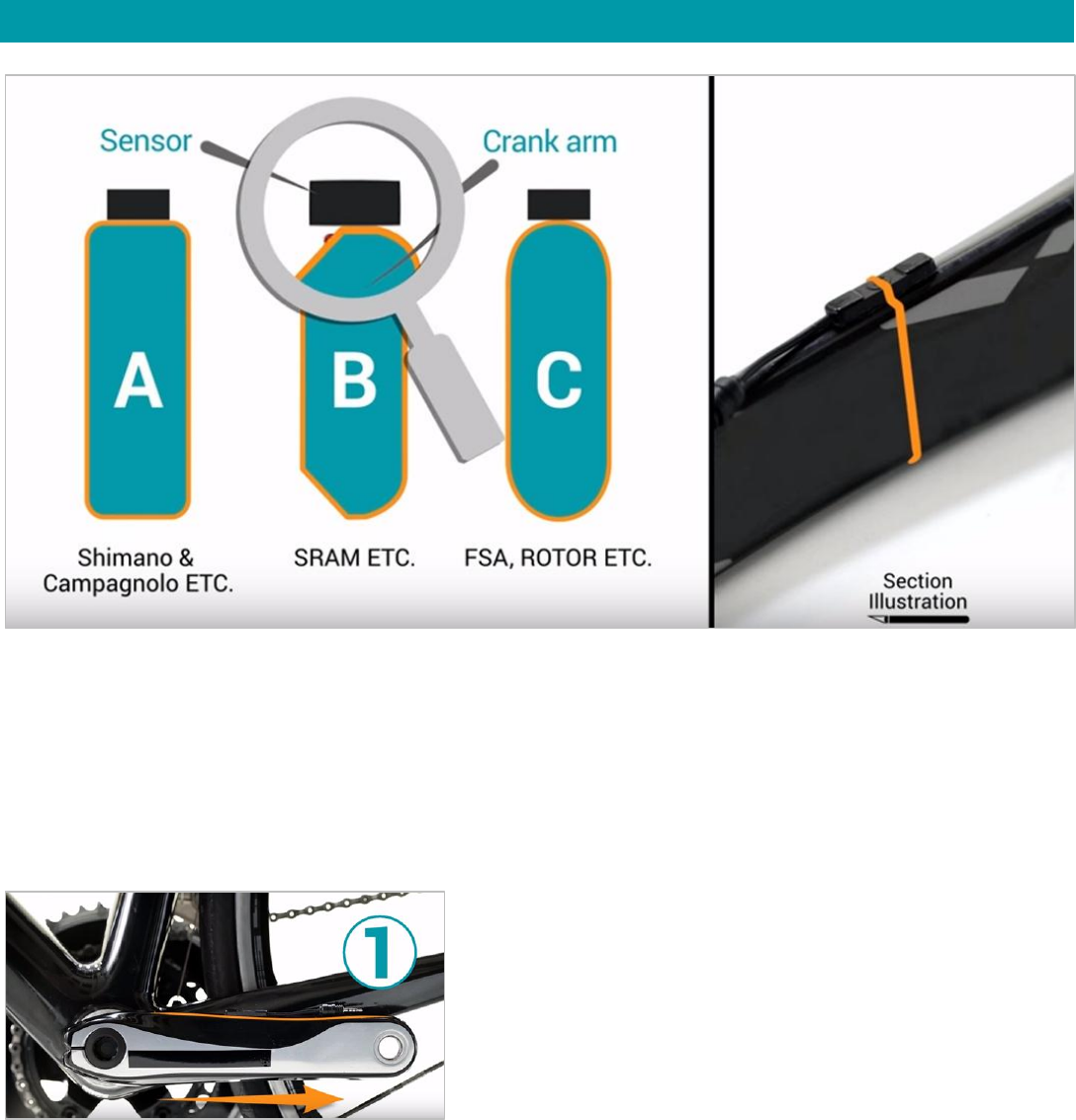
Three Rules for Situating the Sensor in the Perfect Position
Crank arms come in many different designs and shapes. Before gluing the sensors in place, you will need to determine
the proper location, so that when you use the Gluing Tool, you will know where to attach the sensors. Strive for
maximum surface area and fill any gaps with glue.
3 Simple Important Rules
Rule 1:
With the crank arm pointing to the rear of the
bike, the sensor should be glued on the topside.
12
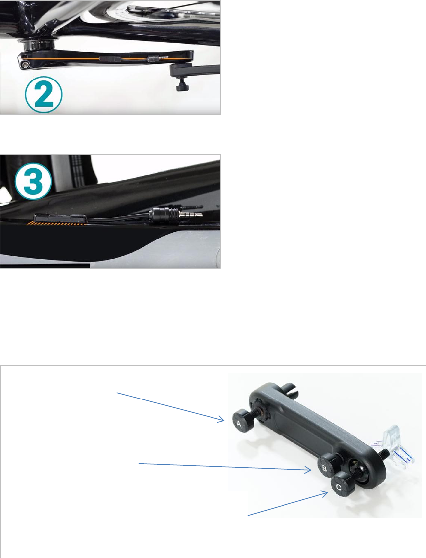
The Gluing Tool
The gluing tool is used to position the sensor on the crank arm, so it is glued in the proper location.
Cleaning the Crank Arms
1. Clean both crank arms thoroughly with the sponge dipped in diluted dishwashing liquid, to remove any dirt and
oil residues. Wipe with paper towel and wait until completely dry.
2. On the left side of the bike, turn the crank so the left crank arm is facing the rear wheel, parallel to the floor at a
three o’clock position.
Bolt A goes into the
pedal hole
Bolt B is used for
fixing the location.
Bolt C has a moveable, transparent
sensor compartment, with two lines that
mark both ends of the sensor.
Rule 2:
When glued, the sensor should be
aligned straight in the center.
Rule 3:
The silver side of the sensor should have
full contact with the surface of the crank
arm when glued. Any gaps should be
filled in with glue.
13
3. Wipe the top side of the crank arm with one of the alcohol pads.
4. Wait a moment for the alcohol to evaporate by itself. (Don’t be tempted to blow on it!)
5. On the right side of the bike, turn the crank so the right crank arm is facing the rear wheel, parallel to the floor
at a three o’clock position.
6. Wipe the top side of the crank arm with the second alcohol pad.
7. Wait the alcohol to evaporate by itself.
8. Put on the protective rubber gloves and keep them on until both sensors have been glued to the crank arm.
9. If your crank arm is carbon, do not apply primer! Continue to the next section, Attaching the Gluing Tool.
If your crank arm is aluminum, turn the left crank arm towards the rear wheel and wipe the primer pad once
along the top part of the crank arm.
Turn the right crank arm towards the rear wheel and wipe the same primer pad once along the top part of the
crank arm.
10. Let the primer undercoat cry for 10 minutes before proceeding with the gluing.
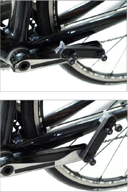
Attaching the Gluing Tool
1. Turn the crank so the left crank arm is facing the rear
wheel, parallel to the floor at a three o’clock position.
2. Attach the gluing tool by plugging Bolt A firmly into the
pedal hole, making sure the gluing tool is aligned with the
crank arm and fits tightly against it.
3. Loosen Bolt B and use Bolt C to find the exact place for the
sensor, according to the 3 rules.
Bolt C has a transparent sensor compartment with blue
lines to indicate exactly where the sensor will be once it is
glued.
4. Use the adjustable ball joint to find the right spot on the
crank arm.
5. Once you have the proper location, tighten Bolt B counter-
clockwise, until the location is securely fixed, that is,
aligned in the center with as much contact as possible.
6. Move the Gluing Tool up and down several times, to make
sure the sensor compartment falls back into the
appropriate place each time. If you detect any
displacement, repeat the steps, rather than taking any
chances once the glue is applied.
14
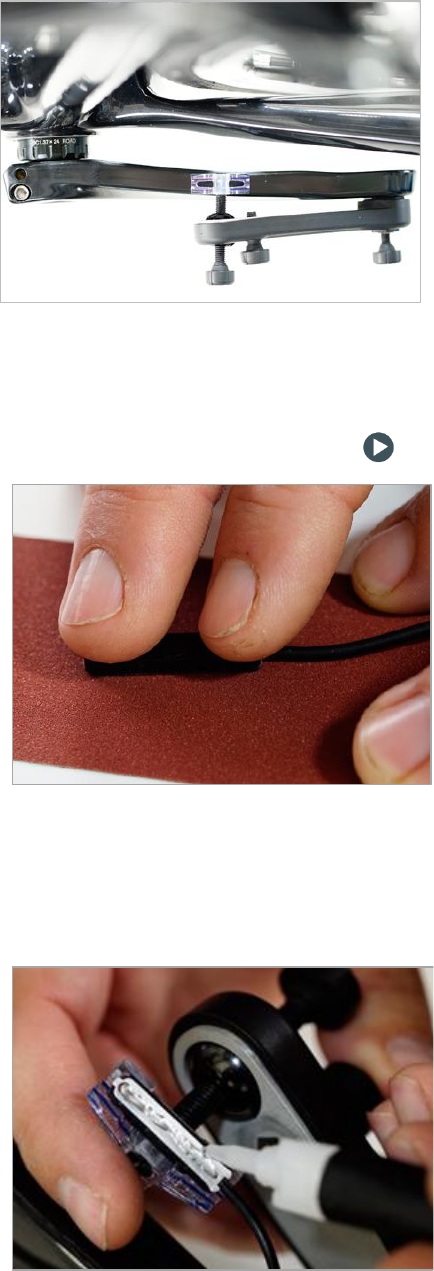
Gluing the Sensors
Preparing the left sensor for gluing
1. Place the sandpaper on a flat surface.
2. With the silver side facing down, scrape one of the sensors
(they are identical) gently on the sandpaper for about 5
seconds, pressing with two fingers, and being careful not to
bend it or to apply too much pressure, until you notice
scratch marks on the silver.
3. Gently place the sensors inside the sensor compartment of
the Gluing Tool, with the plug facing the direction of the
front wheel.
4. Check one last time to make sure the sensor falls into the
proper location, according to the 3 rules.
5. Gently rub one alcohol pad on the silver side of the sensor
and another alcohol pad on the spot it will be glued to, in
order to remove any dirt and oil.
Wait about two minutes, for the alcohol to dry by itself
(without blowing on it).
1. Shake the tube of glue and carefully spread a thin layer of
glue over the entire surface of the sensor, making sure the
cable is not in the way.
2. Place the sensor compartment on top of the crank arm in the
proper location.
3. Press gently on both ends of the sensor, using two fingers, for
about 30 seconds, for the glue to dry.
4. Release your fingers and let the glue dry for another 5
minutes.
5. Carefully detach the sensor from its compartment and
disengage the Gluing Tool.
6. If the sensor is not fully in contact with the surface of the
crank arm (for example if the crank arm is curved) fill in any
gaps with glue.
7. Press Next.
15
Gluing the left sensor:
1. Preparing the right sensor for gluing
2. Prepare the right sensor for gluing in the same manner as you prepared the left sensor.
Gluing the right sensor
Step 8: Installing the Left and Right Comp Units
Tools
1. Shake the tube of glue and on the right side of the
bike, with the crank arm facing the rear wheel, in
the 9 o’clock position, glue the second sensor on
the right crank arm, following the instructions for
gluing the left sensor, then remove the protective
rubber gloves.
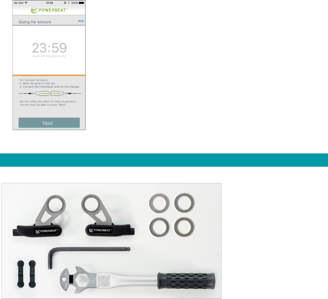
2. Press Next.
3. Wait 24 hours for the glue to dry completely before
continuing the installation.
4. In the meantime charge the comp units so they will
be ready for completion of installation and
calibration tomorrow.
4 washers
2 rubber adhesive strips
2 comp units
Allen key / ratcheting wrench
16
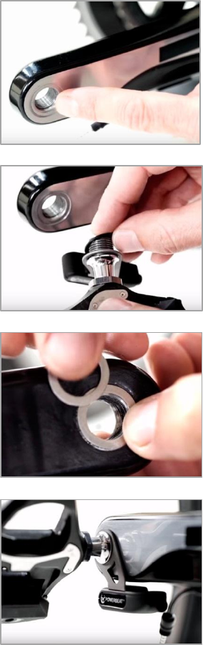
Installing the Left Comp Unit
1. Turn the left crank arm until it faces the front wheel, in the 9
o’clock position.
2. Figure out how many washers or spacers you need:
Feel the space where the thread of the pedal begins and the
external smooth surface of the crank arm. The actual gap
determines how many washers you need to use.
3. Put a washer in the space and if there is still room, add the
second washer, until it sticks out just a little bit over the
surface of the crank arm. (Note that some types of crank
arms may not need any washers.)
4. Place the comp unit marked Left on the spindle thread, then
add the appropriate number of washers.
5. Screw in the pedal, with the socket of the comp unit plug
facing the sensor.
6. Using the Allen key or wrench, tighten the pedal back in
place, making sure the comp unit is aligned with the crank
arm, but not actually touching it.
7. Press Next.
Installing the Right Comp Unit
1. With the right crank arm facing the front wheel in the 3’oclock position, using the comp unit marked Right, install
the Right comp unit, following the instructions for installing the left comp unit.
2. Press Next.
17
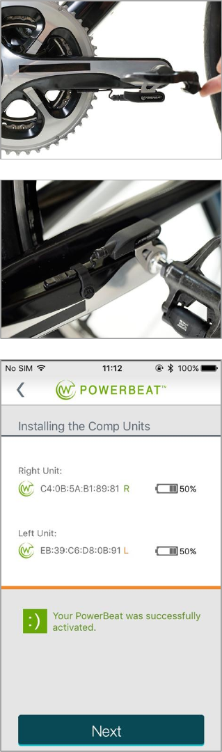
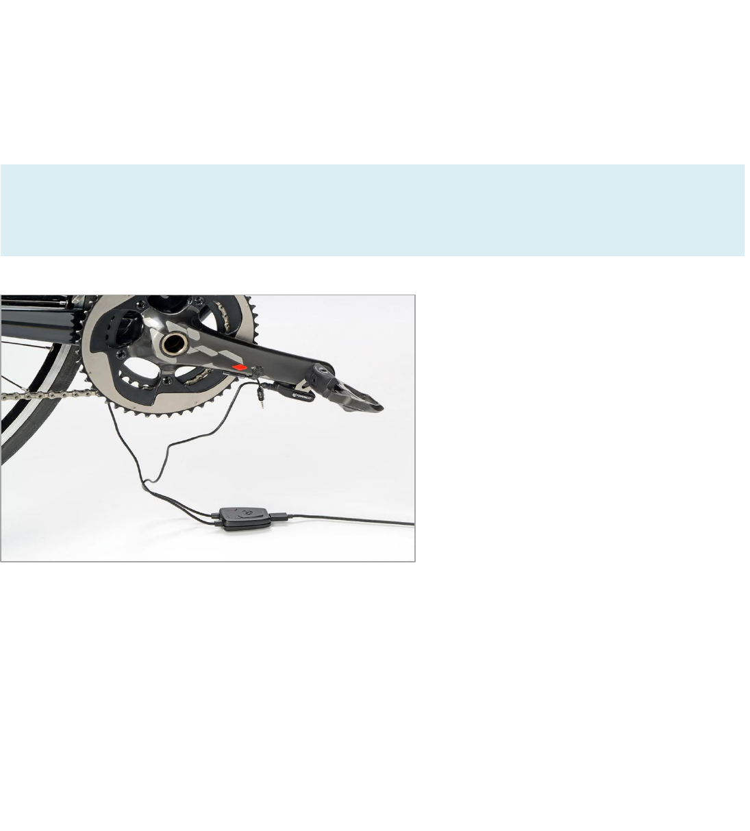
Connecting the Sensors to the Comp Units
Connect the sensor plugs to the comp unit.
Use the adhesive rubber strips to secure the cables to the crank
arms.
Make sure your phone has Bluetooth turned on.
Turn the crank 3 times until the following screen appears.
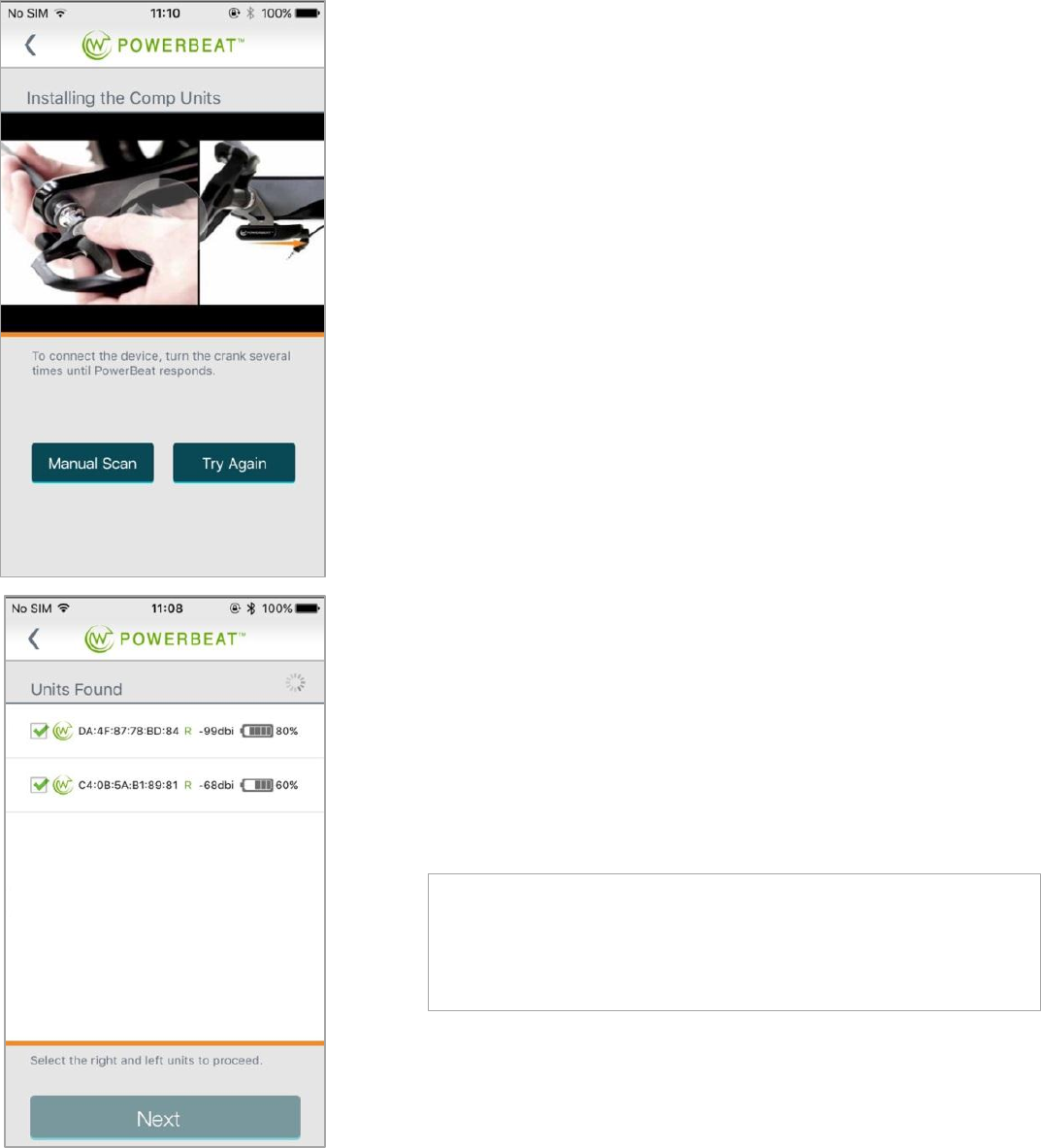
18
If the sensors are not connected the following screen appears. Press
Try Again and keep turning the crank until the Installing the Comp
Units screen appears.
(Or, if you haven’t yet scanned the QR code, see Manual Scan at the
end of this section.)
Once the app has detected the sensors, the Units Found screen
appears.
Check the two units and press Next.
The app notifies you that your PowerBeat was successfully activated.
With you bike still on the trainer, get on and ride for a moment or
two.
You are now ready to calibrate your POWERBEAT. Follow the
instructions on the application.
19
Manual Scan
1. Press Manual Scan to scan the QR code.
2. Select New Devices.
3. When asked “Do you want the selected devices to be your permanent devices?” select Yes.
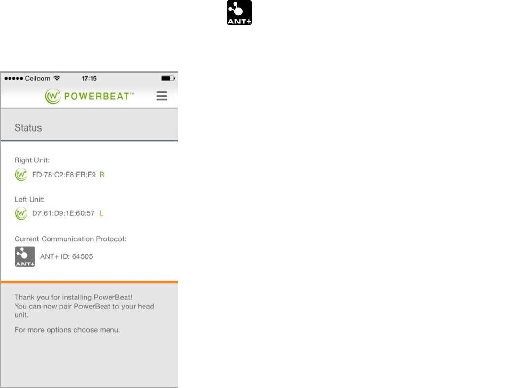
The Status screen appears.
Step 9: Zero Offset Calibration
Before calibrating your POWERBEAT, you need to perform zero offset calibration. We recommend that you watch the
movie in the app before performing zero offset calibration for the first time.
We also recommend that you also calibrate the zero offset, using your head unit, every time you go for a ride. Zero
offset calibration resets the zero offset value of the POWERBEAT sensors when no torque is applied. This is then used as
a baseline for power measurement, to receive an accurate power reading.
It only takes seconds to perform zero offset calibration.
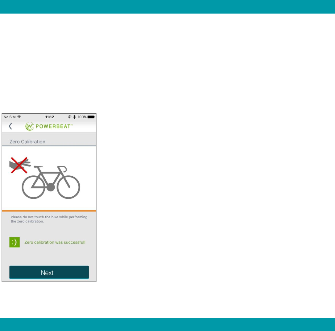
To calibrate the zero offset:
1. Hold your bike upright and make sure nothing is touching the pedals.
2. If you are calibrating the zero offset via the head unit, follow the
instructions for your head unit, otherwise continue.
3. Make sure both POWERBEAT sensors are connected to the comp units.
If you have been riding, you need to unplug them and plug them back
in.
4. Press Set Zero.
5. When zero calibration has been completed the app responds with “Zero
calibration was successful!”
6. Press Next and the Calibration screen appears.
Step 10: Calibration
POWERBEAT calibration is performed through the application. You should only need to calibrate once, when you first
install your POWERBEAT. But keep the 2 water bags and 2 hooks in case you ever need to recalibrate.
20
Tools
For proper calibration it is important that your bike remains steady at all times. You can stand it upside down on the
floor or suspended from a stable work stand.
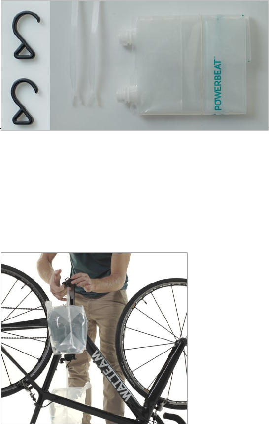
Preparing the Water Bags (Weights)
2 hooks
2 water bags (Before starting
calibration, fill the two bags with
water.)
1. Uncap one of the bags and fill it completely full of tap
water.
2. Jiggle and tilt it, to make sure there are no remaining air
pockets, fill it to full capacity, and then cap it.
3. Fill and cap the second bag in the same way.
4. Attach the plastic handles to the two water bags, by sliding
each handle through the loop and pressing the ends
together until you hear a clicking sound.
5. When it is stable, the Calibrate button becomes active on
the app.
6. Press Calibrate.
21
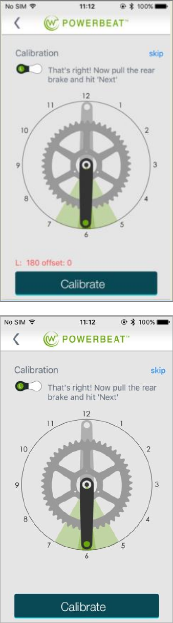
Calibrating the left and right crank
1. Turn the left pedal down to the 6 o’clock position.
2. Using one of the hooks, hang one of the water bags on
the left pedal and let it stabilize in the 6 o’clock position.
The crank arm must be horizontal, that is, parallel to the
floor. Make sure the bag is not touching any part of the
bike and that it is stable.
3. When it is stable, the Calibrate button becomes active on
the app.
4. Press Calibrate
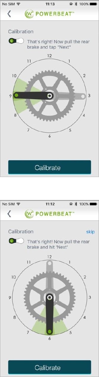
5. Remove the water bag from the left pedal.
6. Turn the right pedal down to the 6 o’clock position.
7. Hang the water bag on the right pedal and let it stabilize
in the 6 o’clock position. The crank arm must be
horizontal, that is, parallel to the floor. Make sure the bag
is not touching any part of the bike and that it is stable.
8. When it is stable, the Calibrate button becomes active on
the app.
9. Press Calibrate.
10. Hang the second water bag on the left pedal.
11. Turn the pedals so the left pedal is in the 3 o’clock
position and the right in the 9 o’clock position. The crank
arm must be horizontal, that is, parallel to the floor. Make
sure the bags are not touching any part of the bike and
that they are stable.
12. When the bags are stable, the Calibrate button becomes
active on the app.
13. Press Calibrate.
22
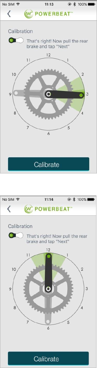
1. Turn the pedals so the left pedal is in the 6 o’clock
position and the right in the 12 o’clock position. The
crank arms must be horizontal, that is, parallel to the
floor. Make sure the bags are not touching any part of
the bike and that they are stable.
2. When the bags are stable, the Calibrate button
becomes active on the app.
3. Press Calibrate.
23
Your POWERBEAT is now calibrated and
ready for your first ride. The next step is
selecting your preferred connection
method.
1. Turn the pedals so the left pedal is in the 9
o’clock position and the right in the 3 o’clock
position. Make sure the bags are not
touching any part of the bike and that they
are stable.
2. When the bags are stable, the Calibrate
button becomes active on the app.
3. Press Calibrate.
4. Turn the pedals so the left pedal is in the 12
o’clock position and the right in the 6 o’clock
position. Make sure the bags are not
touching any part of the bike and that they
are stable.
5. When the bags are stable, the Calibrate
button becomes active on the app.
6. Press Calibrate.

24
Step 11: Pairing your POWERBEAT with your Head Unit
Once you have finished installing your POWERBEAT, you can pair it with your head unit. Carefully read your head unit’s
user manual for a description of the pairing process, as head units differ.
POWERBEAT is compatible with any head unit that works with
(e.g. GARMIN edge 500 or Suunto Ambit 2).
POWERBEAT also supports two modes of , in order to be
compatible with most head units that are available on the market
today:
Single power sensor channel
BLE: e.g. Suunto Ambit 3 or Cateye Padrone smart)
In Single Channel mode the right PowerBeat calculates and
transmits the total power to the head unit .
Dual power sensor channel
Dual: e.g. Polar V800 and V650 or Channel POWERBEAT
mobile App
In Dual Channel mode right and left leg power data are
transmitted independently to the head unit, which then
calculates the total power.
25
Pairing your POWERBEAT with an Head Unit
1. With the device properly installed and connected, select the
ANT+ communication method in the POWERBEAT app.
2. Make sure POWERBEAT is turned on, by spinning the crank
arms several times.
3. Turn on your head unit and perform a Device Search or
alternatively enter the PowerBeat ANT+ ID number in your
head unit (following your head unit’s pairing instructions.)
4. Make sure the displayed ANT+ ID is identical to your
POWERBEAT ID, which is located on the comp units, as well
as inside the box.
26
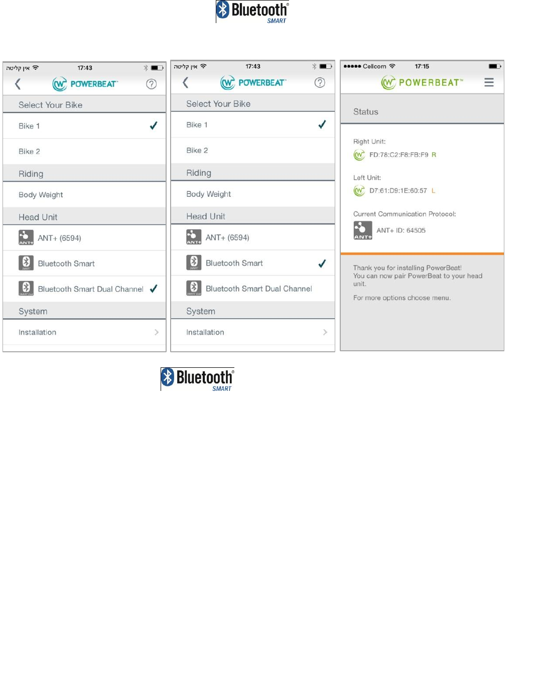
Pairing your POWERBEAT with a Head Unit
To pair your POWERBEAT with a head unit:
1. Check your head unit’s user guide, to find out which mode is supported. If your head unit allows
the pairing of two power meters (left and right), use Dual Channel mode, otherwise use Single
Channel mode.
2. Make sure both POWERBEAT sensors are connected to the comp units.
If you have been riding, you need to unplug them and plug them back in. (standby mode can
also be reached by waiting for a few minutes.
3. Select (Bluetooth Smart)1 in the POWERBEAT app.
4. Unplug your left comp unit.
5. Turn on your head unit and perform a Device Search in your head unit (following your head
unit’s pairing instructions.)
6. Once it is paired, plug in the left comp unit.
7. If necessary, check your head unit’s user guide for more detailed instructions.
8.
27
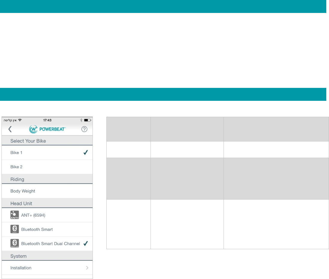
POWERBEAT Menus
When you open the PowerBeat app, the Support screen appears. Select Update to update your firmware. Press < to
display the menu.
Menu Options
Select Your
Bike
Bike 1
Bike 2
For future use
Riding
Body weight
Select to change your body weight
Head Unit
ANT
Bluetooth Smart
Bluetooth Smart Dual
Channel
Displays the current head unit.
Select to change your head unit.
System
Installation
Set Zeros
Calibrate
Support
About

28
LED Status Indications
The LEDs on the comp unit indicate the POWERBEAT status. The following table describes the various states and the
corresponding LED activity.
State
BLE Activity
ANT Activity
LED Activity RED
LED Activity
Green
Description
OFF
None
None
None
None
The plug is out
Charging
None
None
Blinking at 1sec rate when <
90%
Blinking at 1sec rate
when > 90%
Charger
plugged in
Standby
None
None
One short blink when entering
the state
One short blink when
entering the state
Sensor plugged
in
Ready
Advertising
Power Right over
ANT+ if enabled
over ANT+
Blinking at 2sec rate if
measured value
out of range
5 times blinking at 2
sec rate on transition
to Ready mode
After double flip
Power if enabled
over BLE
Power Left over WT
ANT if enabled over
ANT+/BLE 1
Channel
SETUP
Watteam SETUP
service
None
None
One short blink every 3
sec
Application
interface
Ride
Advertising Power
if enabled over
BLE
Power Right over
ANT+ if enabled
over ANT+
None
None
Power if enabled
over BLE
Power Left over WT
ANT if enabled over
ANT+/BLE 1
Channel
FOTA
Advertising as
DFU Only
None
2sec rate 25% DC
blinking when entering
FOTA
DFU Service
None
Alternate 1sec rate 50%DC
while updating 2sec rate 50%
DC for 60sec on failure
alternate 1sec rate
50%DC while updating
100% DC for 30sec on
success

29
Important Safety Information
POWERBEAT uses LiPO rechargeable batteries.
WARNING:
Maximum ambient temperature for charging mode is 109.4 degrees F (43 degrees C) and for discharging mode 122
degrees F (50 degrees C.)
Do not send the comp unit in the cargo of a plane, because the low temperature may permanently damage the LiPO
battery.
POWERBEAT is durable enough to sustain even harsh weather conditions. It has a built-in temperature compensation
mechanism, so the power figures remain consistent regardless of the weather. But never leave the comp unit in an
unattended vehicle, as extreme heat may damage it.
Do not damage, disassemble, or modify the POWERBEAT in any way.
Before washing your bike, either remove the comp units or make sure they are plugged into the sensor. Never wash the
bike if the comp units are unplugged from the sensors.
Make sure the pedals are securely fastened, in accordance with the pedal manufacturer’s instructions.
Do not rotate the pedals if either or both of the comp units are unplugged, as they may get caught in the bike’s
mechanism and become damaged.
Do not connect a power source to the charger if the charger or comp unit appears to be damaged.

30
Troubleshooting
Power and cadence readings are zero, erratic, or inaccurate
First check that the balance readings are correct. If they show just 50%-50% while riding, then make sure that
the batteries are fully charged and that the sensor plug is well connected to the comp unit. If the readings are
still erratic, calibrate or zero offset the device again using the app. Make sure not to touch the crank while
calibrating.
No data is coming from POWERBEAT, although everything else works well.
1. Make sure the POWERBEAT is on. If you are not sure, spin your crank arms several times.
2. Disconnect the sensor plugs from the comp units, wait several seconds, and reconnect them. Then turn
POWERBEAT on by spinning the crank arm and check again.
3. Recharge the comp units.
My head unit doesn’t have the functionality to notify me when the batteries are getting low.
Check the battery level in the PowerBeat mobile application on main riding screen.
Maintenance
PowerBeat is an electronic device that requires proper maintenance.
Maintenance consists mainly of the following four actions:
1. Mobile App updates. We recommend that you upgrade your app whenever a new update is released.
2. Firmware updates, when released.
3. Zero Offset calibration
4. Recharging
Mobile App Updates
Watteam recommends that you automatically update your PowerBeat mobile application whenever an update is
released through the mobile app store (Google Play or Apple Store.)

31
Firmware Updates
Once you have downloaded the WATTEAM POWERBEAT application and registered your POWERBEAT, you will receive
an email notification whenever a new firmware release is available.
NOTES:
Before updating your POWERBEAT firmware, make sure your smartphone battery is charged at least 50%.
During Firmware update keep the bike stationary and do not turn off your smart phone or unplug the
connectors.
During the Firmware update process the LEDs blink alternatively red and green at a rate of about once per
second.
To update your POWERBEAT firmware:
1. Make sure both POWERBEAT sensors are connected to the comp units.
If you have been riding, you need to unplug them and plug them back in.
2. Spin the pedals until the green LED blinks five times.
3. Wait until the application responds.
4. Check the battery level of both POWERBEATs. If it is less than 80%, recharge until it is at least 80%.
5. In the Menu select Update.
6. Follow the instructions in the app.
Changing your POWERBEAT Communication Protocol
Changing to an Head Unit
1. Make sure both POWERBEAT sensors are connected to the comp units.
Spin the pedals until the green LED blinks five times.
2. Select the ANT+ communication protocol in the POWERBEAT app.
3. Turn on your head unit and perform a Device Search or alternatively enter the POWERBEAT the ANT+ ID number
in your head unit (following your head unit’s pairing instructions.)
32
Changing to a Single Channel Head Unit
1. Make sure both POWERBEAT sensors are connected to the comp units.
If you have been riding, you need to unplug them and plug them back in. (standby mode can also be reached by
waiting for a few minutes.
2. Select (Bluetooth Smart) 1 in the POWERBEAT app.
3. Unplug your left comp unit.
4. Turn on your head unit and perform a Device Search in your head unit (following your head unit’s pairing
instructions.)
5. Once it is paired, plug in the left comp unit.
Changing to a Dual Channel Head Unit
1. Make sure both POWERBEAT sensors are connected to the comp units.
If you have been riding, you need to unplug them and plug them back in.
2. Select (Bluetooth Smart Dual Channel) in the POWERBEAT app.
3. Turn on your head unit and perform a Device Search in your head unit (following your head unit’s pairing
instructions.)
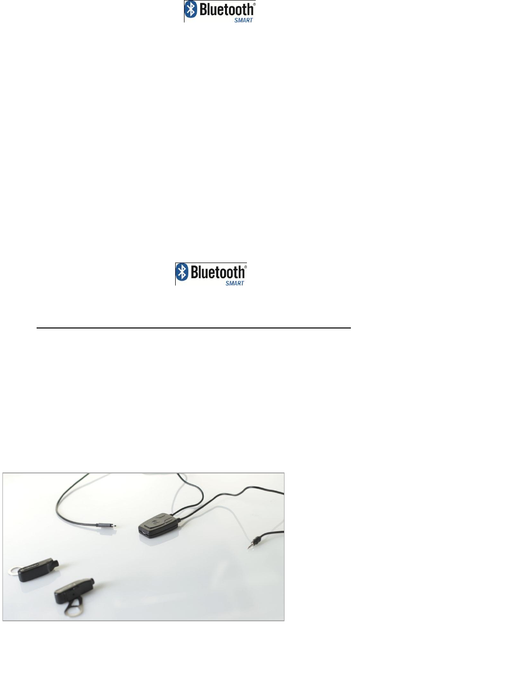
Recharging your POWERBEAT
POWERBEAT is the first power meter to use an eco-friendly rechargeable battery. Each charge provides about 80 hours
of riding time.
POWERBEAT Recharger
and Comp Units
33
When the battery is getting low, you will receive notification in your head unit. (Note that some basic head units do not
have this functionality.)
Charging POWERBEAT is like charging any other USB device. You can charge the comp units either while they are
mounted to your bike or removed, whichever is more convenient.
WARNING:
Maximum ambient temperature for charging mode is 109.4 degrees F (43 degrees C) and for discharging mode 122
degrees F (50 degrees C.)
To recharge your POWERBEATs:
Unplug the sensor cables from the comp units and plug in the two charger plugs instead. Then
plug the USB charger cable into a power source such as a USB charger, home computer, or
laptop. A blinking red light on the comp unit indicates that POWERBEAT is charging. A blinking
green light on the comp unit indicates that the comp unit is charged.
34
Removing the Sensors
Tools
Glue remover
Allen key or ratcheting wrench
X-Acto knife (not supplied)
In the event that you need to remove the sensors:
1. Unplug the sensor cable from the comp unit.
2. Shake the tube of glue remover and apply a generous amount of it around the sensor and wait for 2 hours.
3. Lift the sensor cable using the dull end of the X-Acto knife and slowly start to peel the sensor from the surface of
the crank arm. Be careful not to scratch the crank arm.
4. If the sensor doesn’t come off easily, apply more glue remover and wait for another hour before trying again.
5. If any glue remains on the crank arm after the sensor is removed, apply glue remover, wait a few hours and wipe
it off with paper towel. Don’t wait more than 2 hours, as the glue remover may damage the paint.

35
Appendix A
Warranty
The manufacturer’s warranty is one year from date of purchase.
See the website http://watteam.com/ for details.
Make sure to carefully follow the instructions for installation and calibration, or you may damage the product.
FCC Compliance Statement
This device has been tested and found to comply with the limits for a Class B digital device, pursuant to Part 15 of the
FCC Rules. These limits are designed to provide reasonable protection against harmful interference in residential
installations. This equipment generates uses and can radiate radio frequency energy and, if not installed and used in
accordance with the instructions, may cause harmful interference to radio and television reception.
However, there is no guarantee that interference will not occur in a particular installation. If this device does cause such
interference, which can be verified by turning the device off and on, the user is encouraged to eliminate the interference
by one or more of the following measures:
Re-orient or re-locate the receiving antenna.
Increase the distance between the device and the receiver.
Connect the device to an outlet on a circuit different from the one that supplies power to the receiver.
Consult the dealer or an experienced radio/TV technician.
WARNING! Changes or modifications to this unit not expressly approved by the party responsible for compliance could
void the user’s authority to operate the equipment.
This device complies with FCC Rules Part 15 and with Industry Canada licence-exempt RSS standard(s). Operation is
subject to two conditions: (1) This device may not cause harmful interference, and (2) this device must accept any
interference that may be received or that may cause undesired operation.
Le present appareil est conforme aux CNR d'Industrie Canada applicables aux appareils radio exempts de licence.
L'exploitation est autorisee aux deux conditions suivantes :(1) l'appareil ne doit pas produire de brouillage, et (2)
l'utilisateur de l'appareil doit accepter tout brouillage radioelectrique subi, meme si le brouillage est susceptible d'en
compromettre le fonctionnement.
To comply with FCC Section 1.1310 for human exposure to radio frequency electromagnetic fields and IC requirements,
implement the following instruction:
A distance of at least 0.50 cm. between the equipment and all persons should be maintained during the operation of the
equipment.