Wave Wireless Networking SL8500 Spread Spectrum Transmitter User Manual SPEEDLAN manual
Wave Wireless Networking Spread Spectrum Transmitter SPEEDLAN manual
UserManual.wiki
>
Wave Wireless Networking
>
SL8500 User Manual
users manual
Navigation menu
Upload a User Manual
Namespaces
Wiki Guide
HTML
PDF
Info
Views
User Manual
Discussion / Help
Navigation


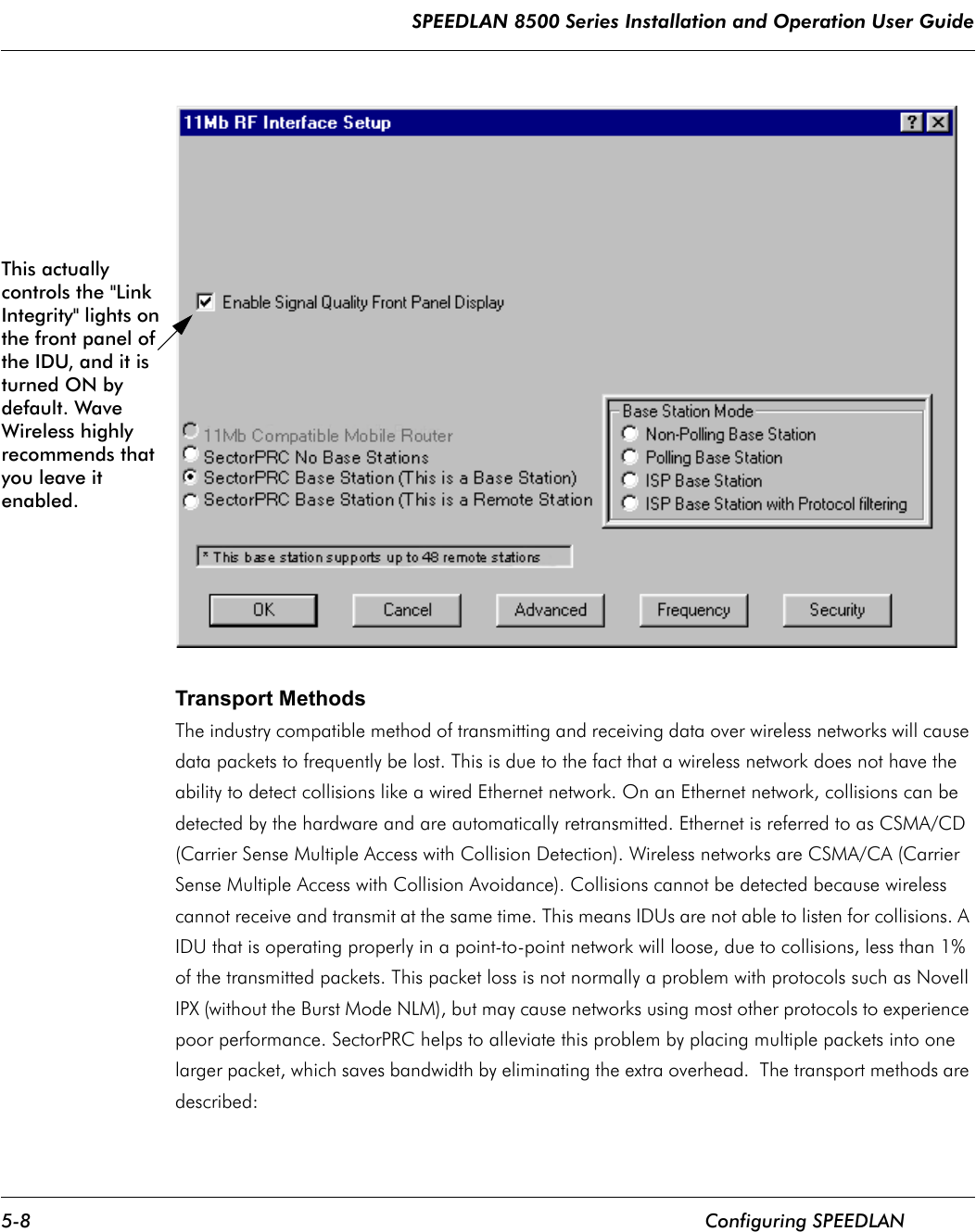

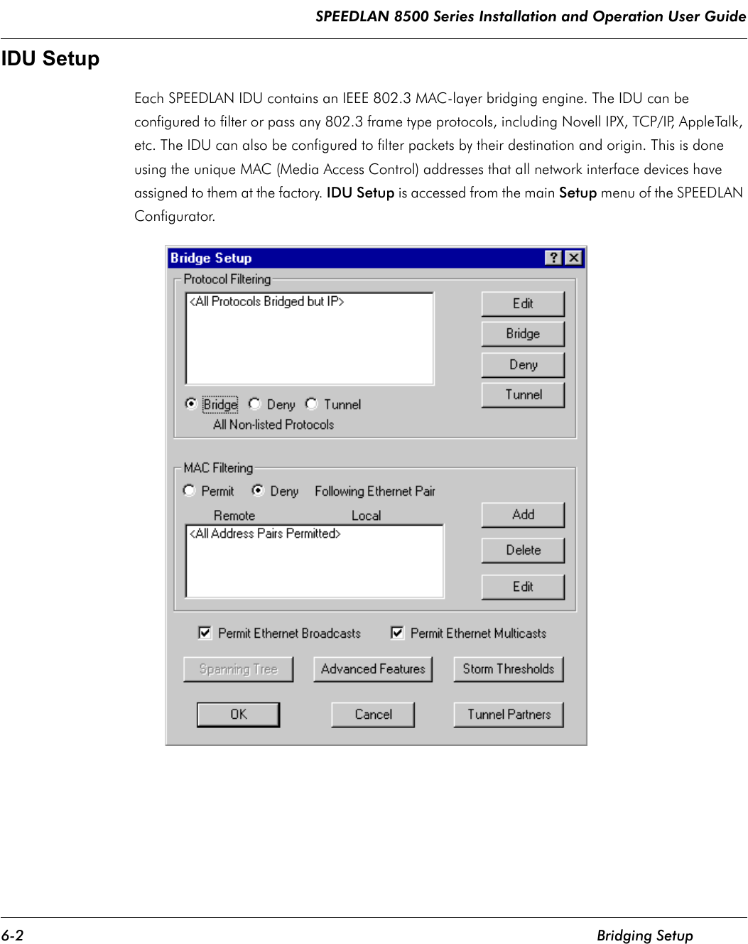
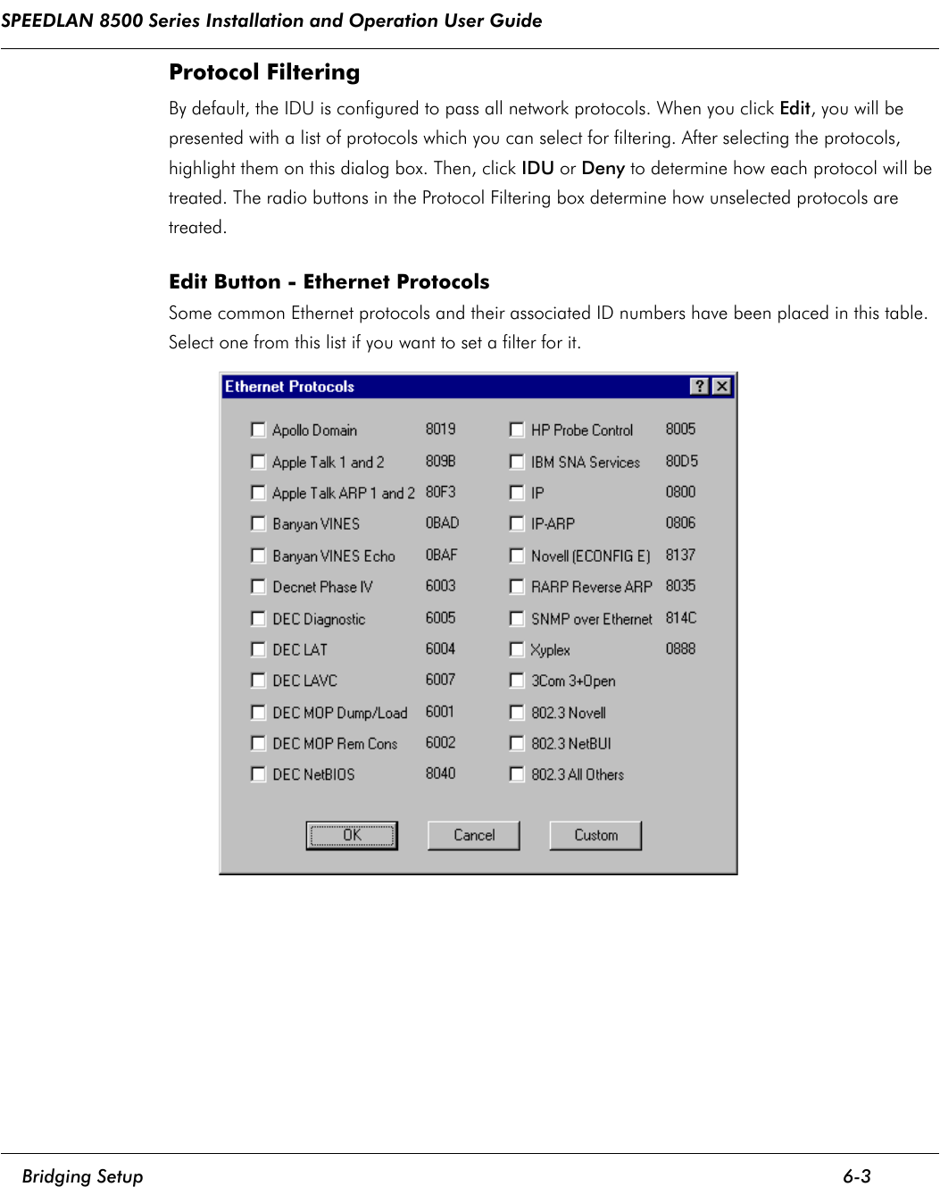
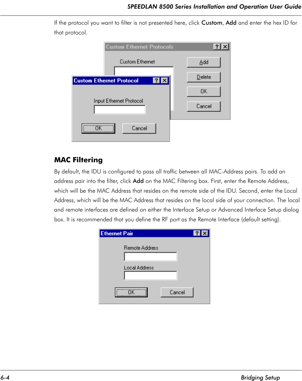
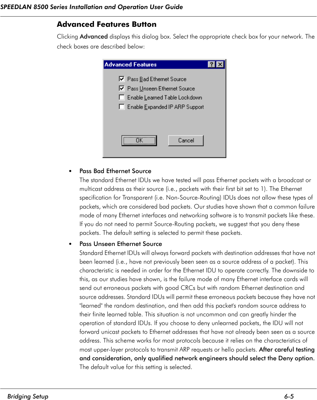


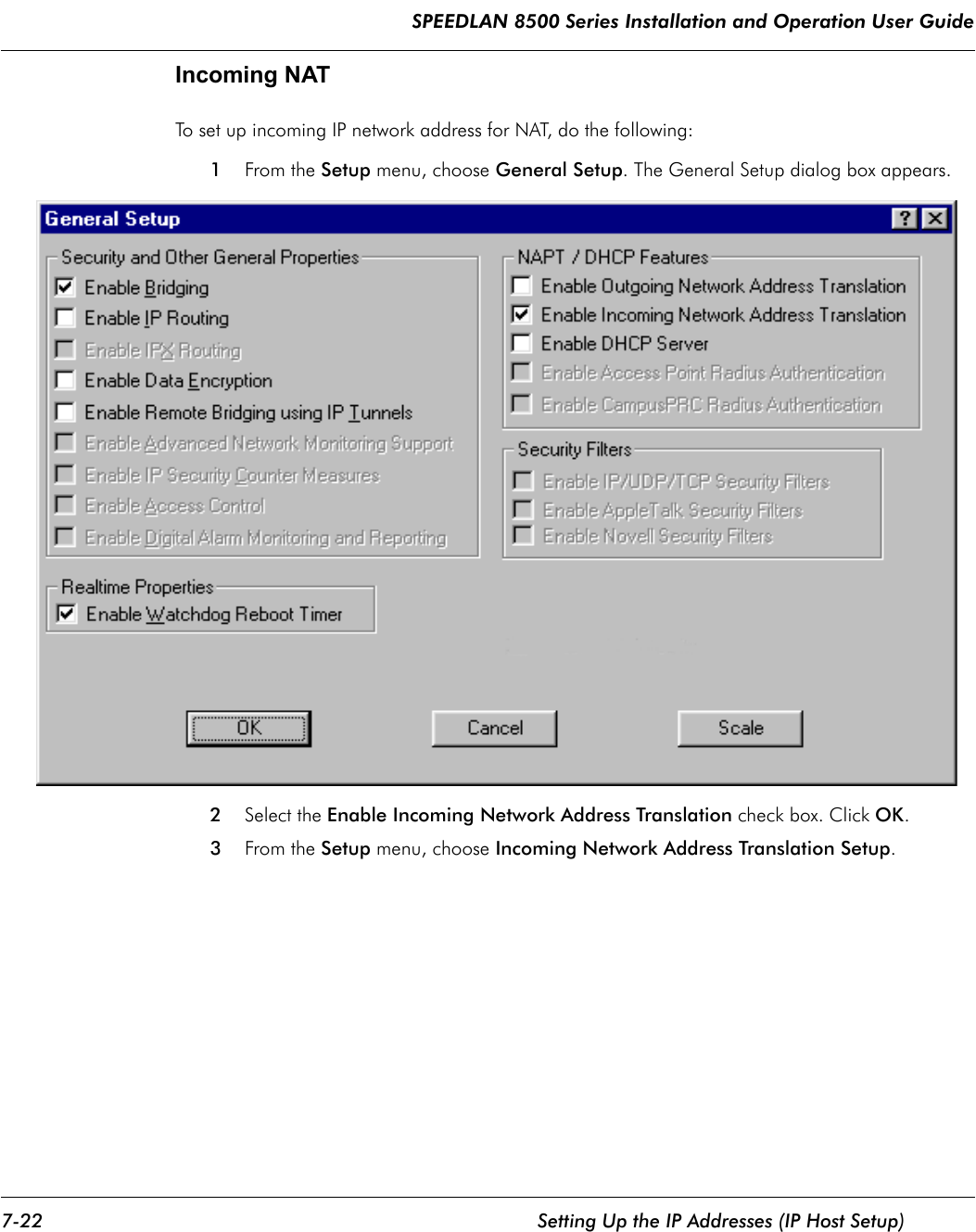
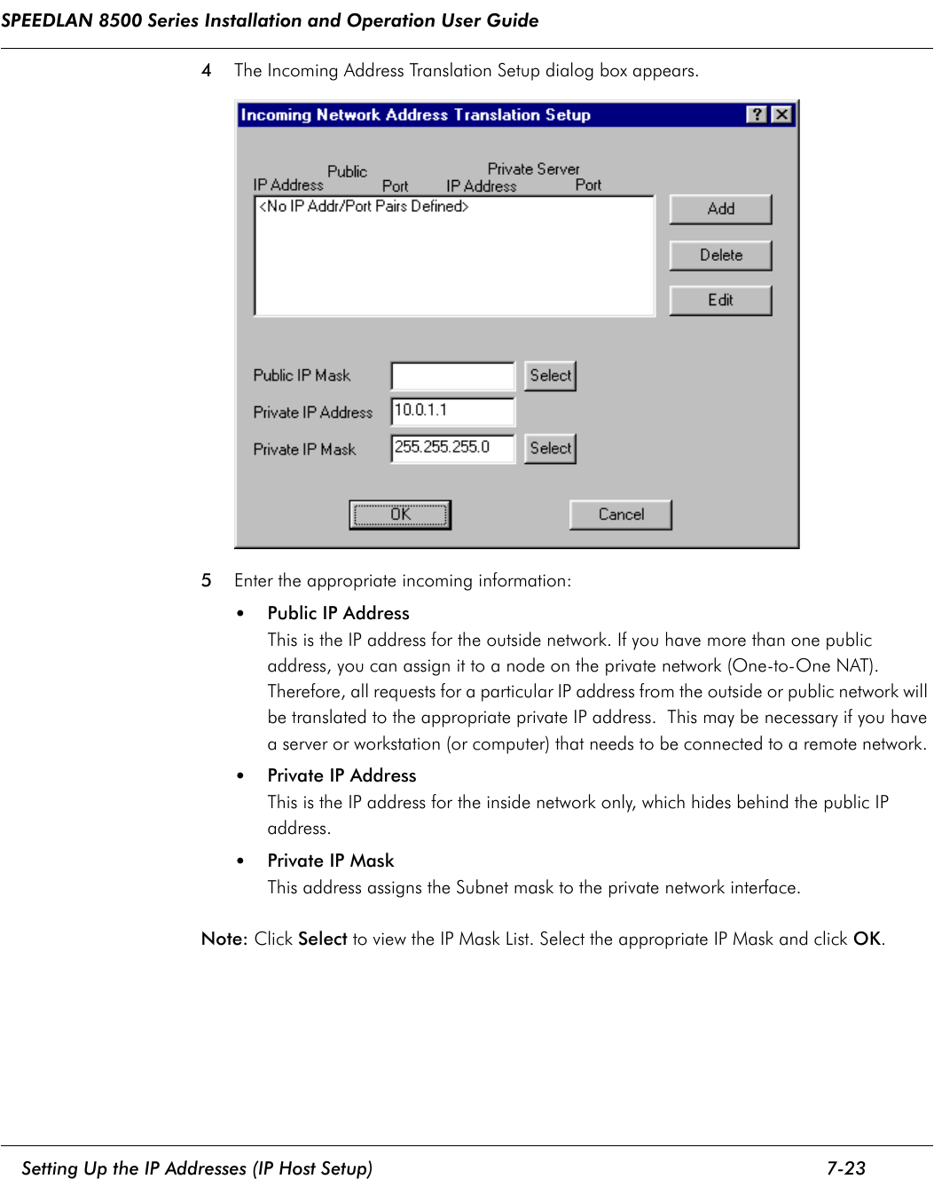
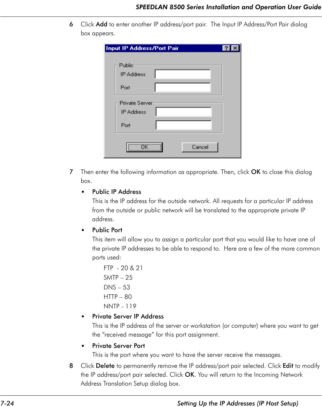
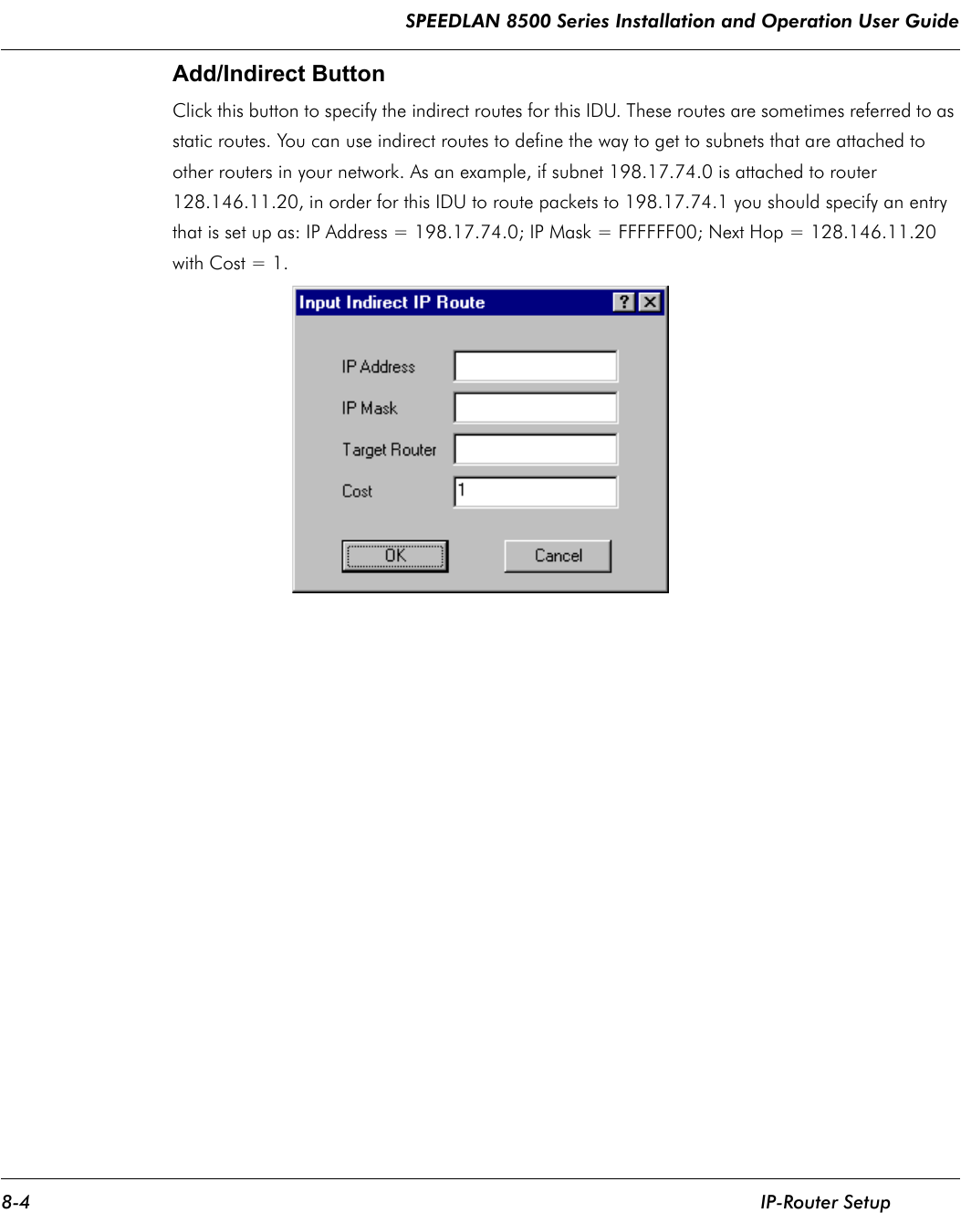
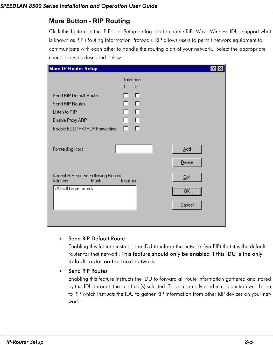
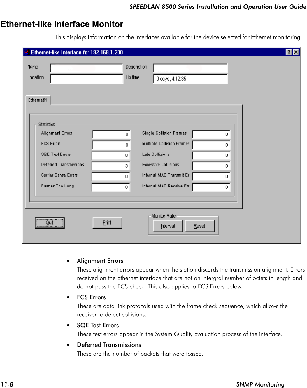
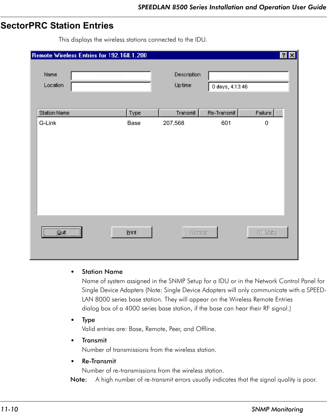
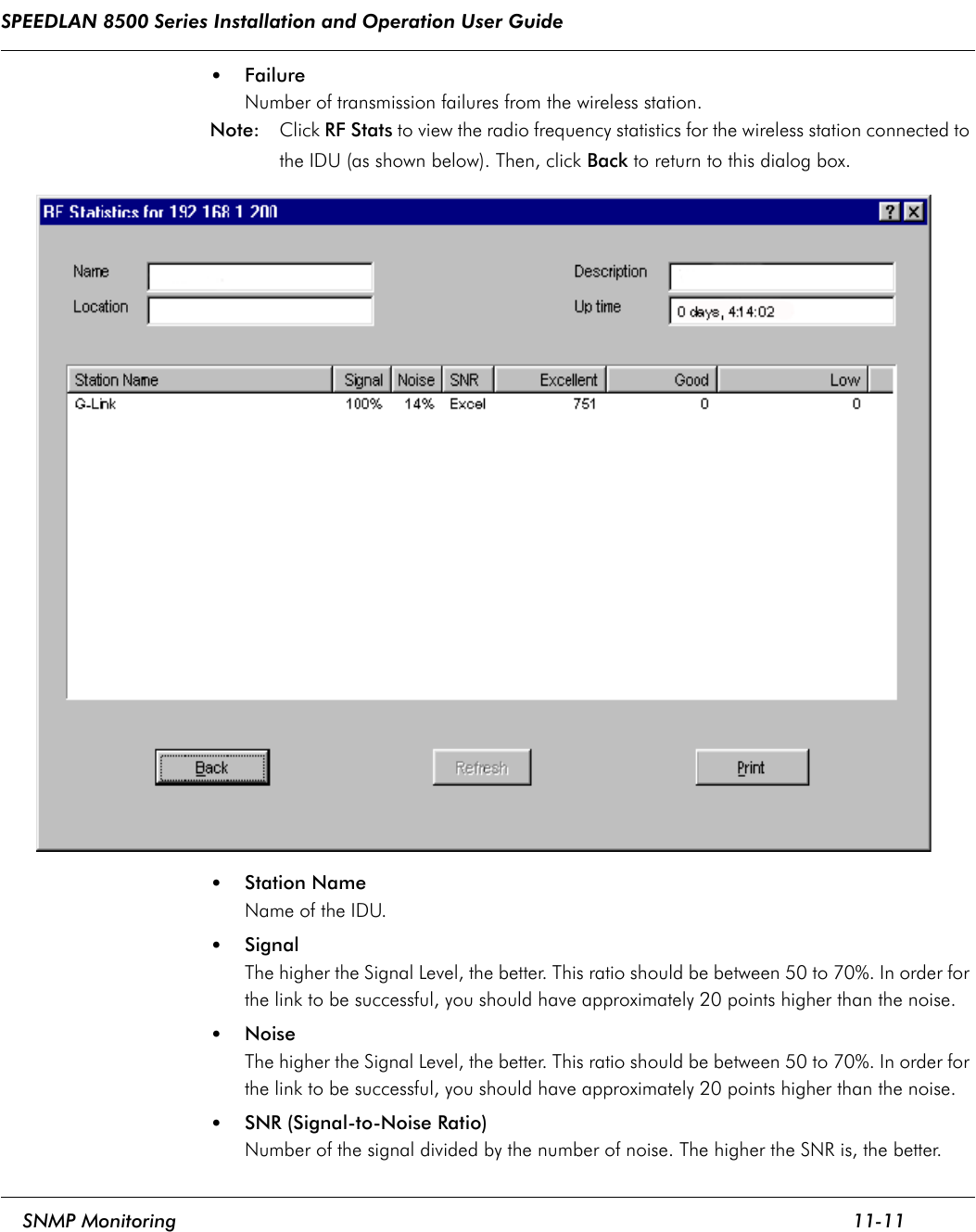
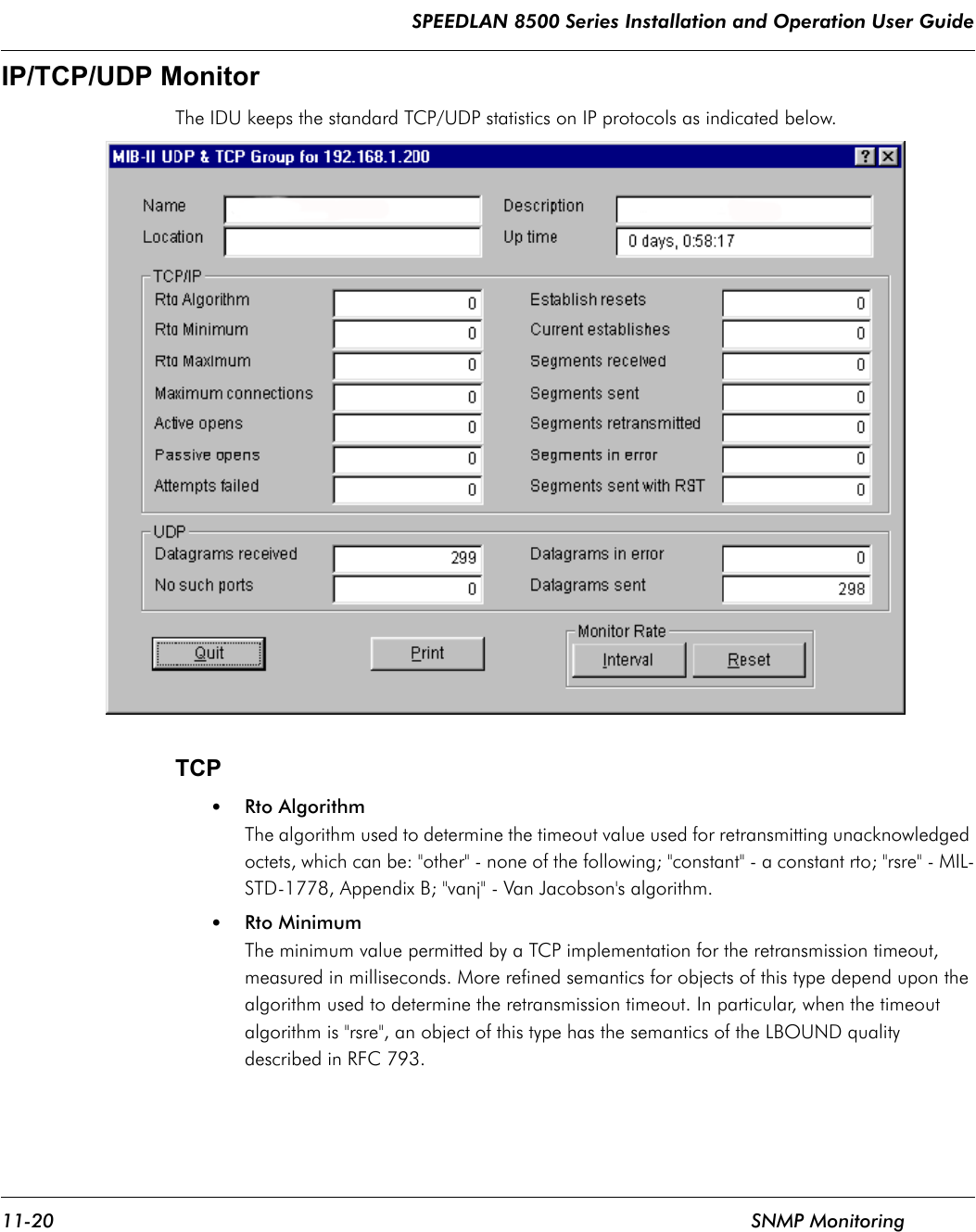


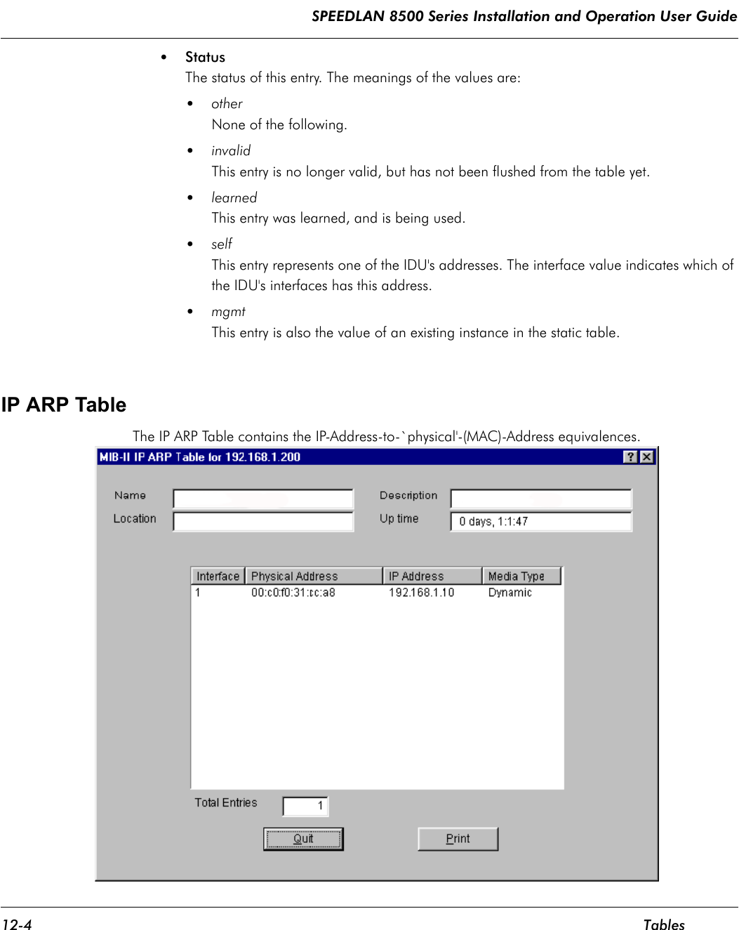

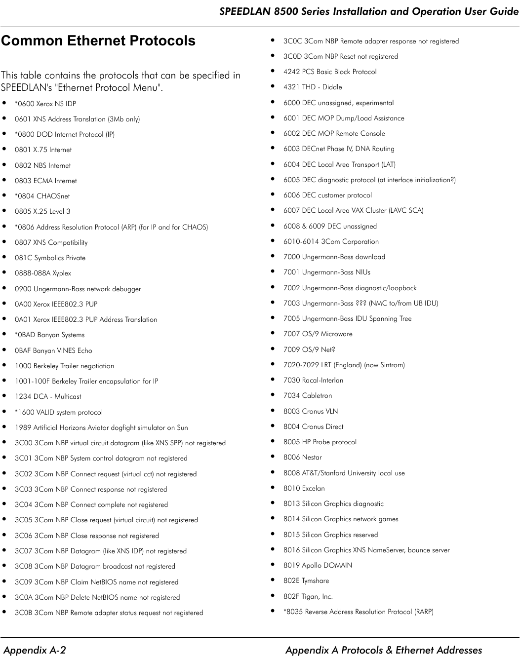
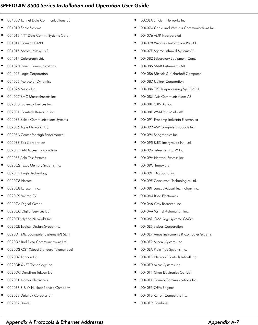
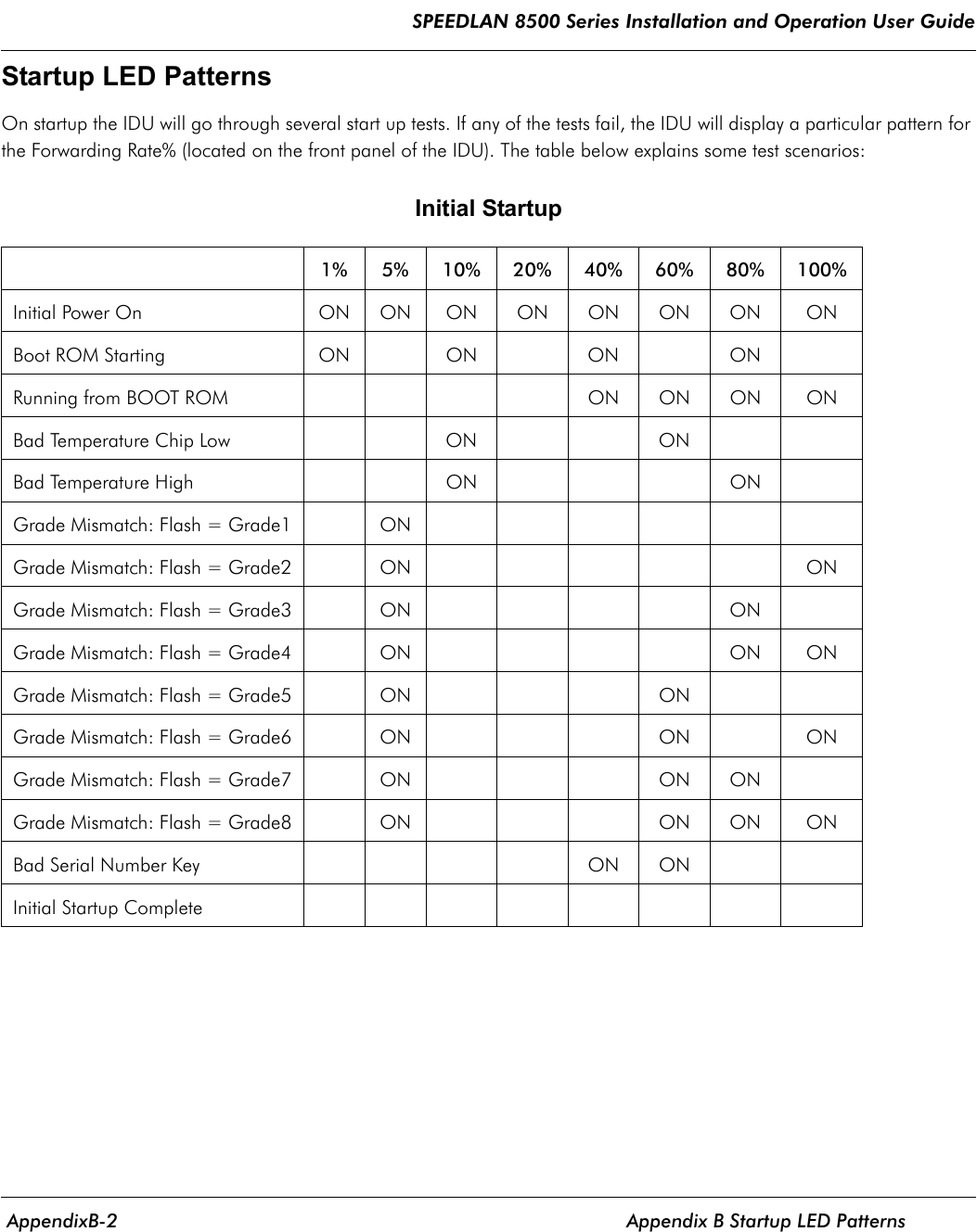
![SPEEDLAN 8500 Series Installation and Operation User Guide Appendix A Protocols & Ethernet Addresses Appendix A-13•080010 AT&T [misrepresentation of] •080011 Tektronix, Inc. •080014 Excelan BBN Butterfly, Masscomp, Silicon Graphics •080017 NSC (National Semiconductor Corp.) •08001A Data General •08001B Data General •08001E Apollo •08001F Sharp Corporation •080020 Sun •080022 NBI (Nothing But Initials) •080023 Matsushita Denso •080025 CDC •080026 Norsk Data (Nord) •080027 PCS Computer Systems GmbH •080028 Texas Instruments •08002B DEC •08002E Metaphor •08002F Prime 50-Series LHC300 •080030 CERN •080036 Intergraph CAE stations •080037 Fujitsu-Xerox •080038 Bull •080039 Spider Systems Ltd. •08003B Torus Systems •08003E Motorola VME bus processor modules •080041 DCA (Digital Comm. Assoc.) •080044 DSI (DAVID Systems, Inc.) •080046 Sony •080047 Sequent •080048 Eurotherm Gauging Systems •080049 Univation •08004C Encore •08004E BICC •080051 Experdata •080056 Stanford University •080057 Evans & Sutherland (?) •080058 DECsystem-20 •08005A IBM •080067 Comdesign •080068 Ridge •080069 Silicon Graphics •08006A ATTst (?) •08006E Excelan •080070 Mitsubishi •080074 Casio Computer Co. Ltd. •080075 DDE (Danish Data Elektronik A/S) •080077 TSL (now Retix) •080079 Silicon Graphics •08007C Vitalink TransLAN III •080080 XIOS •080081 Crossfield Electronics •080083 Seiko Denshi •080086 Imagen/QMS •080087 Xyplex terminal servers •080089 Kinetics AppleTalk-Ethernet interface •08008B Pyramid •08008D XyVision machines •08008E Tandem •08008F Chipcom Corporation •080090 Retix Inc. IDUs •10005A IBM •1000D4 DEC •1000E0 Apple A/UX (modified addresses for licensing) •400003 NetWare (?) •475443 GTC (Not registered!) (This number is a multicast!) •484453 HDS ??? •800010 AT&T (misrepresented as 080010?) •AA0000 DEC obsolete •AA0001 DEC obsolete •AA0002 DEC obsolete](https://usermanual.wiki/Wave-Wireless-Networking/SL8500/User-Guide-234580-Page-169.png)