Wave Wireless Networking SL8500 Spread Spectrum Transmitter User Manual SPEEDLAN manual
Wave Wireless Networking Spread Spectrum Transmitter SPEEDLAN manual
users manual

SPEEDLAN 8300/8350 & 8400/8450 Installation and Operation User Guide
-1
Version 1.0 / Last Revised August, 2000
Wave Wireless Networking
a SPEEDCOM Wireless Company
1748 Independence Blvd. C-5
Sarasota, FL 34234
941-358-9283
www.speedlan.com
SPEEDLAN 8500 Series
Installation and Operation User Guide
Version 1.1 / Last Revised March 21, 2002
Wave Wireless Networking
a SPEEDCOM Wireless Company
7020 Professional Parkway East
Sarasota, FL 34240
941-907-2300
www.wavewireless.com

SPEEDLAN 8300/8350 & 8400/8450 Installation and Operation User Guide
-2
Wave Wireless Networking Copyright Statement
SPEEDLAN® 8500. Copyright © 2001. Wave Wireless Networking.™ All rights reserved. SPEEDLAN and SPEEDCOM are
registered trademarks of Wave Wireless Networking. Wave Wireless Networking and the Wave Wireless Networking logo
are trademarks of Wave Wireless Networking. All other company and product names may be trademarks of their respec-
tive companies.

SPEEDLAN 8500 Series Installation and Operation User Guide
Contents-1
Chapter 1 - Introduction .................................................................................. 1-1
Product Description and Contents................................................................................................1-2
SPEEDLAN 8530 Complete Multipoint System ...............................................................1-2
SPEEDLAN 8250 Building-to Building System ................................................................1-2
SPEEDLAN 8510 to Add On to a Multipoint System .......................................................1-3
Installation Kit Contents ...............................................................................................1-3
Product Features ........................................................................................................................1-3
SPEEDLAN 8500 IDU Features ............................................................................................1-3
ISP Functionality..........................................................................................................1-3
Transparent Ethernet Bridging with Advanced Filtering for Security and Network Reliability.1-4
IP Routing with Advanced Filtering for Security ...............................................................1-4
Wireless Multipoint Protocol .........................................................................................1-4
SNMP Management ....................................................................................................1-4
Additional Functionality ...............................................................................................1-4
SPEEDLAN SNMP Features...........................................................................................1-5
ISP Features................................................................................................................1-5
IP-Router Features .......................................................................................................1-5
Encryption Features (Add-on Option) ............................................................................1-5
SPEEDLAN 8500 Indoor Unit (IDU) ......................................................................................1-5
SPEEDLAN 8500 Outdoor Unit (ODU) .................................................................................1-6
Chapter 2 - Quick Start .................................................................................... 2-1
Rooftop and Tower Installations Warning .....................................................................................2-2
Installation Steps ........................................................................................................................2-2
SPEEDLAN 8500 Instructions ...............................................................................................2-3
Installation Diagrams..................................................................................................................2-6
SPEEDLAN 8500 Series ODU..............................................................................................2-6
Chapter 3 - Hardware....................................................................................... 3-1
Drawings of Components ...........................................................................................................3-2
SPEEDLAN 8500 IDU (Front Panel) ......................................................................................3-2
SPEEDLAN 8500 IDU (Back Panel).......................................................................................3-3
SPEEDLAN 8500 ODU Hardware................................................................................................3-4
Antenna ....................................................................................................................................3-4
Flat Panel Antenna..............................................................................................................3-4
Restoring Factory Default Settings on the SPEEDLAN 8500 IDU......................................................3-5
Upgrading the Firmware .............................................................................................................3-6
Chapter 4 - Overview of Configurator ............................................................ 4-1
Installation and Setup .................................................................................................................4-2
Windows 95/98/NT 4.0 SPEEDLAN Configurator .................................................................4-2
Toolbar and Menus....................................................................................................................4-2
File Menu ..........................................................................................................................4-2
Configuring a SPEEDLAN IDU ......................................................................................4-2
Configuring a Saved Configuration File ........................................................................4-3
Exporting and Importing a Configuration.......................................................................4-3
The Toolbar .......................................................................................................................4-4

SPEEDLAN 8500 Series Installation and Operation User Guide
Contents-2
The Menu Bar ....................................................................................................................4-4
Quick Overview of Other Menus..................................................................................4-5
Chapter 5 - Configuring SPEEDLAN .............................................................. 5-1
General Setup ...........................................................................................................................5-2
Interface & Advanced Interface Setup..........................................................................................5-5
Interface Setup ...................................................................................................................5-5
Advanced Interface Setup ....................................................................................................5-6
The Setup Buttons ......................................................................................................................5-6
Setup 1 Button - Ethernet Setup............................................................................................5-6
Setup 2 Button - 11 Mb RF Interface Setup ...........................................................................5-7
Transport Methods ......................................................................................................5-8
Advanced Button - 11 Mb RF Interface Setup...............................................................5-10
Frequency Button - 11 Mb Frequency Setup ................................................................5-11
Security Button - 11 Mb RF Security Setup ...................................................................5-12
Chapter 6 - Bridging Setup.............................................................................. 6-1
IDU Setup..................................................................................................................................6-2
Protocol Filtering ................................................................................................................6-3
Edit Button - Ethernet Protocols.....................................................................................6-3
MAC Filtering.....................................................................................................................6-4
Advanced Features Button ...................................................................................................6-5
Storm Thresholds Button......................................................................................................6-7
Tunnel Partners Button ........................................................................................................6-8
Chapter 7 - Setting Up the IP Addresses (IP Host Setup) ............................ 7-1
Part I - Quick Overview of IP Addressing ......................................................................................7-2
What is an IP address?........................................................................................................7-2
Internet Address Classes......................................................................................................7-3
In fact, IP defines five classes:.......................................................................................7-4
Subnetting a Network..........................................................................................................7-5
What is a Subnet? .......................................................................................................7-6
What is a Subnet Mask? ..............................................................................................7-6
Diagram of Subnetting a Network.................................................................................7-7
How does a network administrator assign an IP address? .......................................................7-8
What is DHCP? ..................................................................................................................7-8
Figure of DHCP Addressing .........................................................................................7-9
What is NAT?...................................................................................................................7-10
Diagram of Outgoing NAT................................................................................................7-11
Diagram of Incoming NAT ................................................................................................7-12
Part II - Setting Up the IP Address...............................................................................................7-13
Enabling the DHCP Client and Choosing the Appropriate Interface.......................................7-14
Enabling the DHCP Server on the SPEEDLAN ......................................................................7-15
Assigning a Static IP Address..............................................................................................7-18
Part III - Setting Up NAT............................................................................................................7-20
Outgoing NAT .................................................................................................................7-20
Incoming NAT ..................................................................................................................7-22

SPEEDLAN 8500 Series Installation and Operation User Guide
Contents-3
Chapter 8 - IP-Router Setup ............................................................................ 8-1
IP Routing Setup.........................................................................................................................8-2
Add/Direct Button...............................................................................................................8-3
Add/Indirect Button.............................................................................................................8-4
More Button - RIP Routing ...................................................................................................8-5
Chapter 9 - SNMP Setup .................................................................................. 9-1
SNMP Setup ..............................................................................................................................9-2
Chapter 1 0 - System Access Setup............................................................. 10-1
System Access Setup.................................................................................................................10-2
Chapter 11 - SNMP Monitoring ..................................................................... 11-1
Remote Statistics ......................................................................................................................11-2
Interface Monitor .....................................................................................................................11-5
Ethernet-like Interface Monitor...................................................................................................11-8
SectorPRC Station Entries ........................................................................................................11-10
11Mb RF Interface .................................................................................................................11-12
SNMP Monitor .......................................................................................................................11-14
SNMP Messages Received ...............................................................................................11-14
SNMP Messages Sent......................................................................................................11-16
IP Monitor .............................................................................................................................11-17
IP/TCP/UDP Monitor ..............................................................................................................11-20
TCP...............................................................................................................................11-20
UDP ..............................................................................................................................11-22
ICMP Monitor ........................................................................................................................11-23
ICMP Messages Received ................................................................................................11-23
ICMP Messages Sent.......................................................................................................11-24
Chapter 12 - Tables........................................................................................ 12-1
System Information...................................................................................................................12-2
IDU Learn Table.......................................................................................................................12-3
IP ARP Table ............................................................................................................................12-4
IP Route Table .........................................................................................................................12-6
IP/TCP Connection Table..........................................................................................................12-8
IP/UDP Listener Table ...............................................................................................................12-9
Local IP-Address Table............................................................................................................12-10
Chapter 13 - Analyzing Wireless Equipment............................................... 13-1
Select Another Device...............................................................................................................13-2
Analysis Polling Interval.............................................................................................................13-3
Wireless Link Test .....................................................................................................................13-3
Antenna Alignment...................................................................................................................13-8

SPEEDLAN 8500 Series Installation and Operation User Guide
Contents-4
Glossary for Standard Data Communications
Appendixes
Appendix A
Protocols & Ethernet Addresses
Common Ethernet Protocols.......................................................................................................... 2
Common Ethernet Vendor Addresses ............................................................................................. 4
Common Ethernet Multicast Addresses......................................................................................... 14
Common Ethernet Broadcast Addresses ....................................................................................... 15
Appendix B
Startup LED Patterns
Startup LED Patterns ..................................................................................................................... 2

Chapter 1
Introduction

SPEEDLAN 8500 Series Installation and Operation User Guide
1-2 Introduction
Product Description and Contents
The SPEEDLAN 8500 series provides high performance 11 MB interconnectivity between buildings
and offers an alternative to Telco leased and fiber optic lines. The SPEEDLAN 8500 series also "up-
converts" the 2.4 GHz radio to the 5.8 GHz band (during transmit), and "down converts" 5.8 GHz to
2.4 GHz on receive. No user adjustment, configuration or provisioning is required.
The SPEEDLAN 8500 series offers three different systems:
SPEEDLAN 8530 Complete Multipoint System
This is a complete 5.8 GHz point-to-multipoint system designed to connect three remote buildings at
distances up to 3 miles (5 Km). This system contains everything required for a base station and three
remote buildings including:
•(4) IDU bridges with 10/100 Ethernet interface
•(4) 100’ IF cables
•(4) 5.8 GHz ODU
•(1) 17 dBi 60 degree sectorial base station
•(3) 23 dBi 5.8 flat panel antenna
•(1) 17 dBi sectoral antenna
•(4) Installation Kit
SPEEDLAN 8250 Building-to Building System
This 5.8 GHz system is designed for building-to-building connectivity at distances up to 5.5 miles
(8.8 Km). This system contains everything required to link two buildings including:
•(2) IDU bridge with 10/100 Ethernet interface
•(2) 100’ IF cables
•(2) 5.8 GHz ODU
•(2) 23 dBi 5.8 flat panel antenna
•(2) Installation Kit

SPEEDLAN 8500 Series Installation and Operation User Guide
Introduction 1-3
SPEEDLAN 8510 to Add On to a Multipoint System
If you need to connect an additional building to a multipoint-system that is already in place, then use
this add-on. This will also provide 5.8 GHz in the building as well. This system includes:
•(1) IDU
•(1) 100’ IF cable
•(1) 5.8 GHz ODU
•(1) Installation Kit
•Antennas are sold separately (no antenna included with 8510)
Installation Kit Contents
The Installation Kit contents include:
•Product registration card
•SPEEDLAN CD containing: Product manual and Configuration management software
•Electrical tape
•U-bolt antenna hardware
•Cable sealant putty
•Lightning arrestor
•Grounding clamps
•Wire zip ties
•DC injector
Product Features
SPEEDLAN 8500 IDU Features
ISP Functionality
The SPEEDLAN 8000 products are tailored to fit the needs of Internet Service Providers and
Broadband Telecommunications Providers. Two features particularly useful to Internet Service
providers are the additional of Network Address Translation (NAT) and Dynamic Host Server Protocol
(DHCP). NAT helps to ensure network security and allows an entire company to share a single global
IP address for communication on the Internet. For example, a company can provide its clients with
just one IP address, allowing access to the company’s firewall only. DHCP servers provide efficient
use of IP addresses by assigning them dynamically or statically to the wireless IDU location. DHCP

SPEEDLAN 8500 Series Installation and Operation User Guide
1-4 Introduction
allows network administrators to assign dynamic IP addresses for the period of time needed to
connect to the Internet or network, whereas static IP addresses are beneficial to users that need to
maintain a "constant" connection. This reduces the load on the entire wireless network.
Transparent Ethernet Bridging with Advanced Filtering for Security and
Network Reliability
SPEEDLAN 8500 products support what is known as Transparent Ethernet Bridging with no Spanning
Tree or Source Routing support. Since the SPEEDLAN 8500 IDUs provide network security between a
local LAN and a campus or enterprise wide network, and since using multiple IDUs in a Spanning
Tree could compromise this security, the Spanning Tree scenario is not supported. In addition, the
SPEEDLAN 8500 IDUs can filter packets based on protocol type or MAC address pairings. These
features can add a significant measure of security and network reliability to a network
interconnection.
IP Routing with Advanced Filtering for Security
The SPEEDLAN 8500 IDUs support IP Routing in addition to bridging. It can be used to add routing
capability when an IP router may be a more appropriate choice.
Wireless Multipoint Protocol
SectorPRC features provide multipoint networking, improved performance, and increased reliability.
In multipoint networks, the IDU central base station manages the flow of data within the radio cell.
When necessary, packets are repeated or retransmitted by this IDU, allowing communications
between multiple remote networks by using the IDU CPE.
SNMP Management
SNMP wireless and wired link management may be administered from any Ethernet network or
remotely from the Internet. The SNMP MIB II, IDU MIB, and Ethernet-Interface MIB come with the
IDUs, so you can use SNMP to monitor a number of SPEEDLAN 8500 parameters, including RF-
signal quality and noise level.
Additional Functionality
•Split component design provides maximum link distance
•10/100BASE-T Ethernet Interface
•Bridging Features
•Protocol Transparent Bridging
•IP Routing

SPEEDLAN 8500 Series Installation and Operation User Guide
Introduction 1-5
•Filtering by Ethernet Multicast, Broadcast and Bad Packets
•Filtering by Protocol
•Filtering by Ethernet Address Pair
•Generic Ethernet Tunneling through IP Networks
•Learned Table Lockdown
•Expanded IP ARP Support
•Automatic Broadcast Storm Protection and Notification
•Supports up to 48 Remote Buildings
SPEEDLAN SNMP Features
•IP "ping" Support
•IP SNMP Support (MIB II, Ethernet, Interface, SNMP, and IDU MIB)
•IP SNMP WaveLAN
•IP SNMP Trap Support
•SNMP Access Lists
ISP Features
•DHCP Server
•Outgoing and Incoming NAT
IP-Router Features
•IP Static Routing with Direct and Static Routes
•ICMP Messages, Default Router, and Subnet Support
•SNMP Support for All Router-Related MIB Variables
•RIP Support
Encryption Features (Add-on Option)
•Data Encryption of Wireless Packets
SPEEDLAN 8500 Indoor Unit (IDU)
The SPEEDLAN 8500 Indoor Unit (IDU) presents unparalleled performance and features for any
organization needing high-speed connectivity between enterprise LAN-to-LAN applications such as
school or campus network connections, banking, manufacturing, hospitals and clinics. This enables

SPEEDLAN 8500 Series Installation and Operation User Guide
1-6 Introduction
a central Ethernet LAN to be connected with one or more branch office LANs up to 7.5 miles
(12 Km).
The SPEEDLAN 8500 IDUs present a significant breakthrough in LAN connectivity by offering these
high performance IDUs that outperform other wireless spread spectrum systems in the industry. These
IDUs contain full remote SNMP management and security in an affordable package. This enables
you to monitor a number of SPEEDLAN 8500 parameters including RF-signal quality and noise level,
as well as transparent bridging with advanced filtering for security and network reliability.
The SPEEDLAN 8500 IDUs are mounted inside the building and connect to the outdoor antenna
using up to 200 feet of low loss RF antenna cable.
SPEEDLAN 8500 Outdoor Unit (ODU)
The SPEEDLAN 8500 Outdoor Unit (ODU) provides bi-directional frequency (translation) from the
2.4 GHz band to the 5.8 Ghz band. It allows the use of existing WLAN equipment on the 5.8 GHz
band, especially since this band provides relief from the interference which is present on the 2.4
GHz band in many areas. The 5.8 GHz band is also useful for backbone or backhaul use.
All functions of the SPEEDLAN 8500 ODU are transparent to the user, which means no adjustments
are required. Channel assignment and network set-up are both performed at the radio card (or
access point).

Chapter 2
Quick Start

SPEEDLAN 8500 Series Installation and Operation User Guide
2-2 Quick Start
Rooftop and Tower Installations Warning
Rooftop, tower and mounted equipment (IDUs) installations are extremely dangerous and incorrect
installation can result in death, injury, or property damage. These installations must be
performed by professional antenna installers only.
Important Notes:
•ODUs cannot be mixed. Each node on a link, or network for multipoint links, must use the
same ODU type.
•No item substitutions are allowed.
•There is no Single Device Adapter for the SPEEDLAN 8500 series, and Wave Wireless Net-
working does not intend to produce one in the future.
•The lightning arrestor, included with each product, must be placed between the IDU and
ODU. For more information, see Installation Diagrams, page 2-6.
Installation Steps
Installation instructions are specific to customers who purchased Installation Kits from Wave
Wireless. To view a diagram of the installation instructions below, see Installation Diagrams,
page 2-6.
The directions below contain installation procedures for the items included in the SPEEDLAN 8500
antenna (and amplifier) kit. If you do not have an item included in the instructions below, contact
Wave Wireless Networking.
If you are having trouble and need a full site installation, contact Wave Wireless Networking for services and fees.

SPEEDLAN 8500 Series Installation and Operation User Guide
Quick Start 2-3
SPEEDLAN 8500 Instructions
To install the SPEEDLAN 8500, do the following:
Step 1. Line of Sight
Before installing the antenna and ODU, make sure a clear line of sight exists. Line of sight can be
defined as each antenna having a clear transmission path between the two antennas with no
physical obstructions (e.g., trees, buildings, hills, etc.). Be sure to look level with the center of origin
of the transmission (the middle of the antenna). Do the same from the remote location. Any
disruption of the signal path due to trees, buildings or any other obstructions may cause the link to
function improperly. If you see any such obstruction between the two antennas, move one or both
antennas to a different location on the building, or install on antenna mast or tower to gain height.
Step 2. Mount the Antenna
a) On a side building mount, as in the diagram at the end of this section, position the bracket
so there will be at least three feet (one meter) above the roof line of the building where the
pole is attached; this leaves room for the antenna and reduces signal loss from building
reflection.
b) Allow for as much space between the wall brackets as possible while still maintaining the
antenna height that is necessary. For extended poles, additional wall brackets may be nec-
essary.
c) Assemble the antenna and mount it to the pole using the U-bolt hardware included in the
installation kit. Make sure all bolts and screws are fastened tightly.
d) Fasten the pole to the brackets. Position the antenna, point it in the appropriate direction,
and tighten the screws.
Step 3. Mount the ODU to the mast or tower
a) Mount the ODU case to the mast or tower using the U-bolt mounting hardware included in
the installation kit. The RF connectors would not face downward but sideward. For more
details, see Installation Diagrams, page 2-6.
b) Tighten bolts with an open-end wrench, but do not overtighten them.
c) Make sure you mount the ODU as far away as possible from the other radio transmitters,
regardless of their frequency range. Make sure there are no obstructions in front of the
antenna.
d) Waterproof the connectors using cable sealant putty provided in the installation kit.

SPEEDLAN 8500 Series Installation and Operation User Guide
2-4 Quick Start
Step 4. Run the Cabling
The installation kit comes with two lengths of cable with ready made connectors that fit your
particular installation.
a) Attach the shorter cable from the ODU to the antenna, making sure the connectors are
screwed on tightly.
b) Attach the lightning arrestor to the end of the shorter cable.
c) Attach the longer cable to the lightning arrestor.
d) Drill the hole needed to get through the wall, being very careful not to drill into power con-
duits or other utilities in the wall.
e) Feed the cable through the wall and run it to the SPEEDLAN IDU.
f) Fasten all cabling securely to the pole and walls using clamps and zip ties. Do not run cable
over electrical devices such as fluorescent lights because these devices will interfere with the
operation of the IDU. Be careful when pulling or fastening the cable that unnecessary pres-
sure does not break your connectors.
g) Seal all outdoor connections with the black electrical tape and black sealant insulation putty
that comes in the installation kit. First, wrap the connectors tightly with the tape. Then, care-
fully wrap the connectors evenly with the insulation putty, making certain to leave no cracks
that would allow water to penetrate the seal.
Step 5. Ground the Antenna
a) Mount the lightning arrestor to a solid surface.
b) Run the grounding wire from the lightning arrestor to a proper ground source, such as a
grounding rod or roof ground wire.
c) Perform a bench test to make sure the equipment is working properly.
d) Seal the entire lightning arrestor with the black waterproof sealant insulation putty that
comes in the installation kit. Note: The lightning arrestor is NOT
NOTNOT
NOT waterproof.
Step 6. Connect the Wireless IDU to the Power Supply
a) Make sure the switch on the power supply is set to the proper voltage (110V or 230V AC).
b) Connect the power cord’s IEC 320 female outlet to the IEC 320 male power inlet on the
back panel of the SPEEDLAN IDU.
c) Connect the power cord to an external power outlet (110V or 230V AC).

SPEEDLAN 8500 Series Installation and Operation User Guide
Quick Start 2-5
d) Mount the DC injector indoors, as shown in the installation diagram at the end of this sec-
tion. Attach the DC injector to a flat surface using screws or bolts through the mounting
flanges. Do not over set the power supply. The DC injector will inject the DC power to oper-
ate to amplify into the transmission line, which allows the coaxial cable to carry RF and DC
power to the ODU mounted on the mast or tower. Make sure that the DC injector is
grounded as well.
Step 7. Connect the Wireless IDU to any Available Outlet of the Ethernet LAN
a) Connect the RJ-45 connector on a standard Ethernet cable to the RJ-45 port on the back
panel of the IDU.
b) Connect the other end of the Ethernet cable to your Ethernet hub, switch or router.
Step 8. Repeat If Needed
Repeat Steps 1-6 for all of the SPEEDLAN 8500 IDUs that will be communicating with this one.
Step 9. Check Functionality Using the LED Indicators.
When the installation is complete, activate the SPEEDLAN IDU. The radio will automatically transmit
a “hello” packet to the other IDU(s) to initiate communication. When a remote IDU is located, the
IDU will synchronize themselves with each other once communication is established. Then, the IDU
will start forwarding data packets to the wireless LAN that is connected to them. When the IDUs are
“handshaking” correctly, you will see the receive and transmit lights blink on and off as they
communicate.
As the IDUs forward data back and forth to one another, you may occasionally see a collision light
on the display panel. This is a normal aspect of networking. A solid collision light displayed on the
front panel indicates that the particular interface is not able to detect a link.
If you think the IDU is not configured or operating properly, try troubleshooting the problem by
seeing Appendix B Startup LED Patterns, page Appendix B-1.
SPEEDLAN 8500 Series Installation and Operation User Guide
2-6 Quick Start
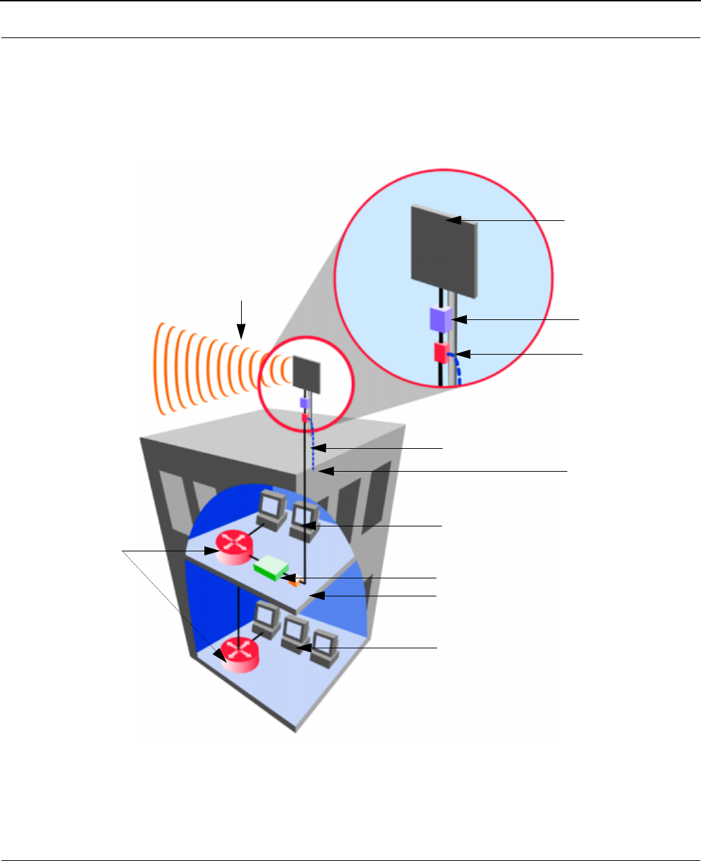
Installation Diagrams
SPEEDLAN 8500 Series ODU
The diagram below displays where the main components are located and how the signal is up
converted from 2.4 GHz to 5.8 GHz.
All outdoor cable connections and lightning arrestors must be insulated with waterproof
electrical putty.
DC injector
Antenna
Lightning arrestor
or router
r
5.8 GHz
(e.g., LMR 400)
2.4 GHz RF cabling
Router, switch
or hub
IDU
Network
Network
is grounded
Lightning arrestor
ODU
(this example shows
a flat panel antenna)

Chapter 3
Hardware
SPEEDLAN 8500 Series Installation and Operation User Guide
3-2 Hardware
Drawings of Components
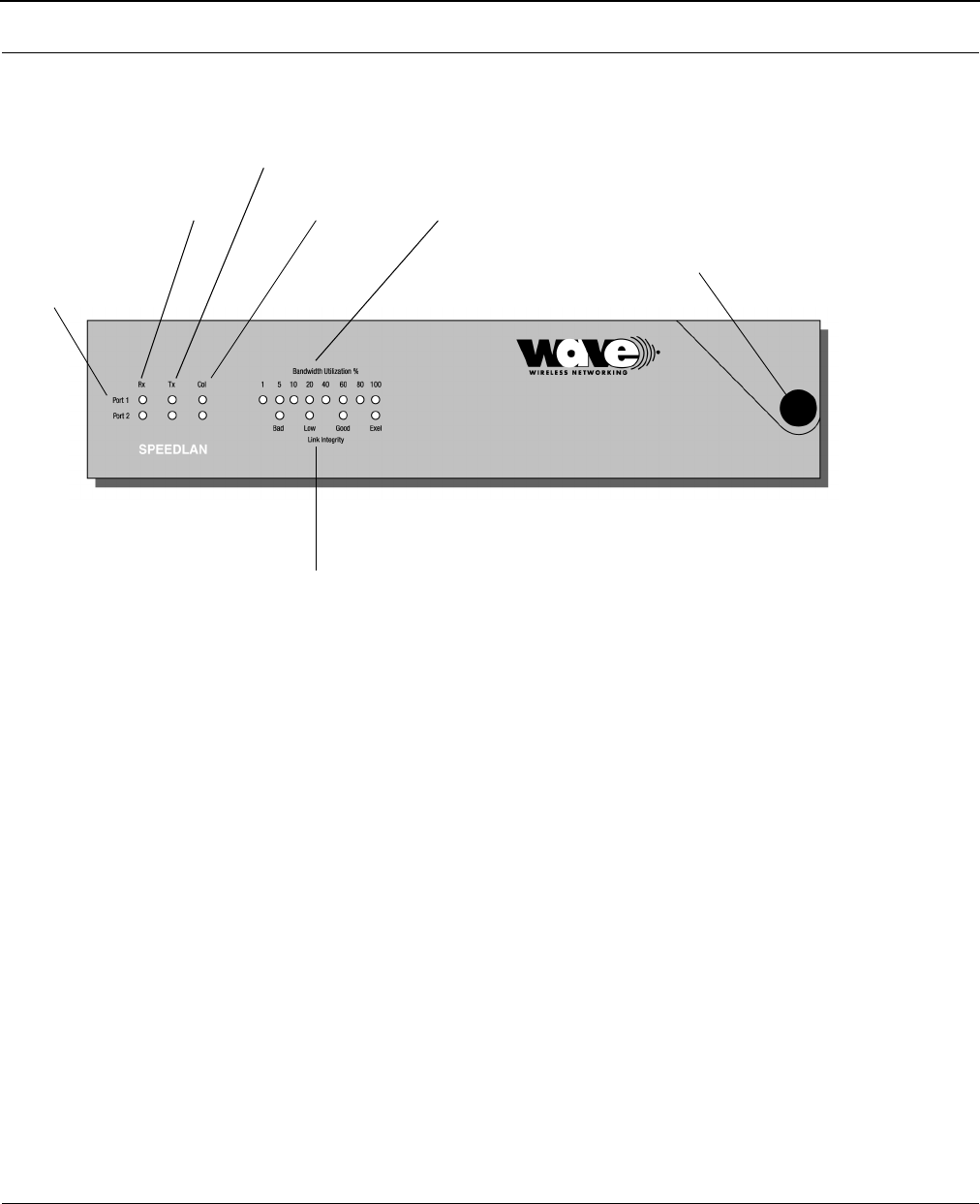
SPEEDLAN 8500 IDU (Front Panel)
•Rx
This light will blink whenever a packet is received on the related interface.
•Tx
This light will blink whenever a packet is transmitted on the related interface.
•Collision
This light will blink whenever a collision occurs. It will remain “solidly lit” when a link cannot
be established on that interface.
•Port 1
Wireless Interface.
•Port 2
10/100 Base-T LAN Interface.
•Forwarding Rate/Bandwidth Utilization
Percentage of wireless bandwidth currently being used.
•Link Integrity
Gives a visual indication of the RF signal strength.
•Power Switch/Button
Used to activate power to the IDU.
Ports:
Port 1: Wireless
Interface
Port 2: 10/100 Base-T
LAN Interface
Receiving
Blinking
Light
Transmitting
Blinking
Light
Collision
Blinking
Light
Forwarding Rate/Bandwidth Utilization
Power Button
Transmission
Quality
SPEEDLAN 8500 Series Installation and Operation User Guide
Hardware 3-3
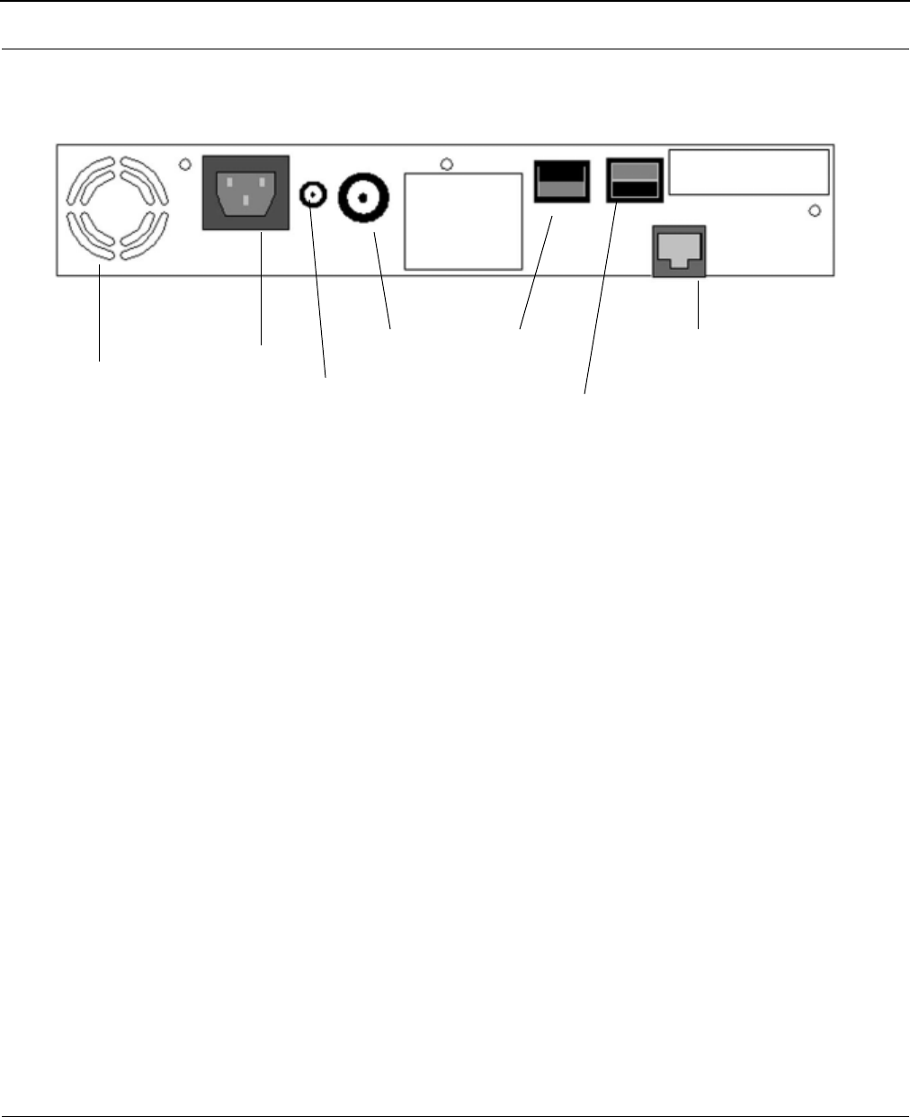
SPEEDLAN 8500 IDU (Back Panel)
•Power Input
AC power input.
•DC Amp Power
Provides power for optional external amplifier.
•RF Cable Input/Output
Interface for RF cable. The connector used for this port is a reverse TNC bulkhead.
•Factory Default
Places the SPEEDLAN into a factory default mode for troubleshooting purposes.
•Base Boot
Puts the IDU in a mode to accept a firmware upgrade. Not to be used for any other
purpose.
•10/100Base-T Ethernet Port
Standard RJ-45 Ethernet port. The Ethernet interface is capable of operating either 10 or
100 Mbps. By default it is configured for 10 Mbps Ethernet.
•Serial Number
The silver sticker on the back of the SPEEDLAN is where you will find the serial number of
your IDU. All products are tracked using their respective serial numbers. If you ever need
technical assistance, we will need the serial number to determine the exact build of your
equipment.
Screws
Fan
Power Input
DC Amp
Power
RF Cable
Input/Output
Factory
Base Boot
Switch
Ethernet
PortDefault
Switch
SPEEDLAN
1) This device may not cause
harmful interference.
2) This device must accept
any interference that may
cause undesired operation.
Warning
Do not connect units back-to-back
without RF signal attenuation.
SPEEDLAN 8500 Series Installation and Operation User Guide
3-4 Hardware
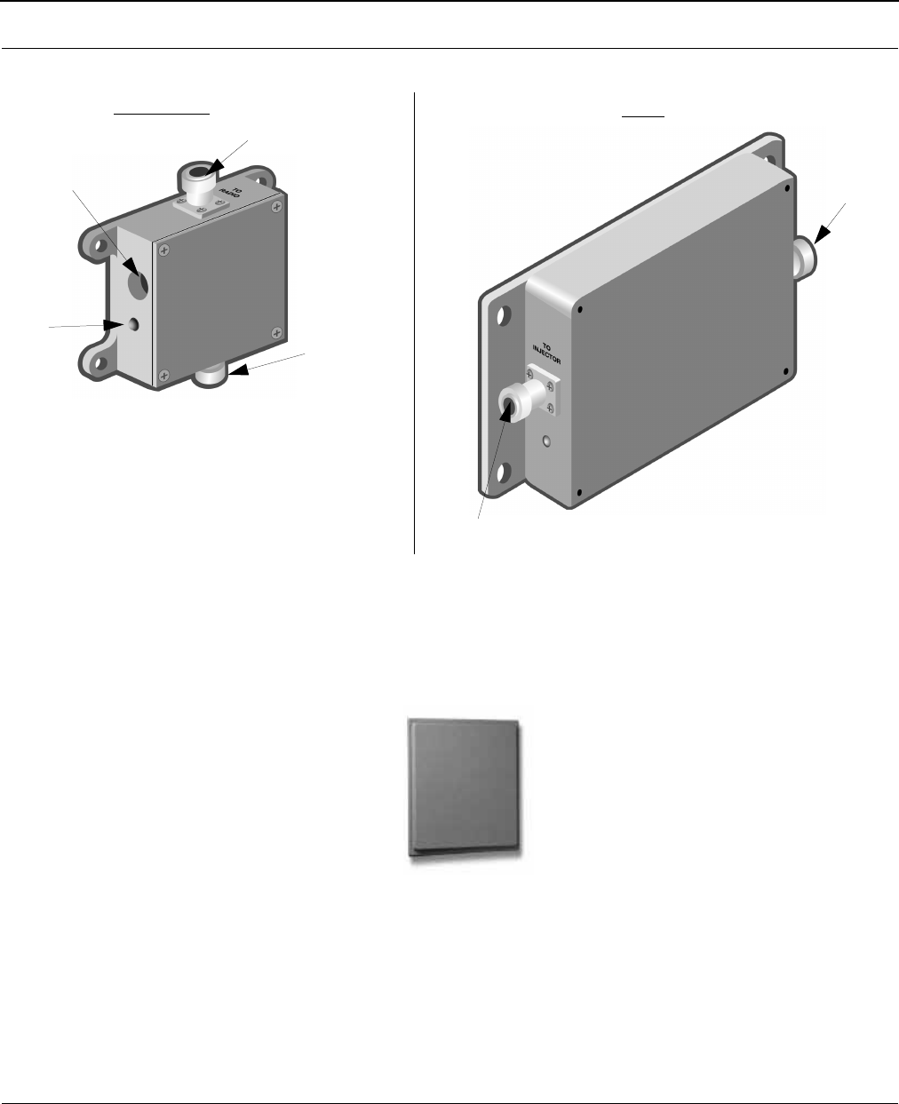
SPEEDLAN 8500 ODU Hardware
Antenna
Flat Panel Antenna
The SPEEDLAN 8500 series uses a flat panel antenna. This antenna provides a gain level of 23 dBi,
which works with the 8520 and 8530 models. There is also a 17 dBi sectoral that works with the
8530 model. Contact Wave Wireless Networking for more information.
(inside building)
ODU
DC Injector
To DC injector
Power LED
To p o w e r s u p p l y
To radio
To amplifier
To a n t e n n a

SPEEDLAN 8500 Series Installation and Operation User Guide
Hardware 3-5
Restoring Factory Default Settings on the SPEEDLAN 8500 IDU
To restore the factory default settings on the IDU, do the following:
1Turn off the SPEEDLAN IDU.
2Connect the PC to the IDU using a crossover Ethernet cable or using 2 Straight-through
cables and a hub.
3Under the Network Neighborhood on your PC, change your IP address to 198.17.74.195
and assign a Subnet Mask of 255.255.255.0. You will also need to remove any gateways
that were defined in your TCP/IP properties.
4You will be asked if you want to reboot your PC. Click Ye s.
5On the back panel of each IDU, depress the small black Factory Default switch to the UP
position. For normal operation the switch should be depressed in the down position. Power-
up the IDU and let it reboot.
6The IDU is temporarily in factory default mode.
7On your PC, start the SPEEDLAN Configurator.
8From the File menu, choose Open Remote Config.
9In the space for IP Address, enter 198.17.74.254. This is the IP Address of the IDU while in
factory default mode. Click on OK, and then OK again. You should see a message con-
firming that the IDU configuration was read properly.
10 From the File menu, choose Save Remote Config.
11 All the configuration settings on the IDU have now been returned to a factory default state.
You may now configure the IDU for operation on your network.

SPEEDLAN 8500 Series Installation and Operation User Guide
3-6 Hardware
Upgrading the Firmware
You will need to update your firmware if the old one is damaged or additional functionality has been
added. To upgrade the firmware, do the following:
1Turn the SPEEDL AN IDU o ff.
2Connect the PC to the IDU using a crossover Ethernet cable, or using 2 Straight-through
cables and a hub.
3Under the Network Neighborhood on your PC, change the IP address to 198.17.74.195
and assign a Subnet Mask of 255.255.255.0. You will also need to remove any gateways
that were defined in your TCP/IP properties.
4You will be asked if you want to re-boot your PC. Click Ye s .
5On your PC, start the SPEEDLAN Configurator.
6From the File menu, select Open Config. Then, select the appropriate .Bin file.
7Then from the File menu, choose Upload Software. A dialog box will appear with an IP
address in it. Click Scan; this will bring up another dialog box with the IP Address of the
SPEEDLAN. This IP Address will be 198.17.74.254. At this point click OK, and confirm the
IP Address in the first dialog box is 198.17.74.254. Then, click OK again.
8Next a menu will appear requesting a MAC Address, as well as a Passkey. You can only
receive these from Wave Wireless. You will enter these two variables and click the OK but-
ton. There will be a sequence of dialog boxes, which will warn you that you are about to
reload the Flash ROM with a new .Bin file. Click OK for all of them. This will cause the IDU
to reboot.
9Allow the IDU to reboot normally.
10 The IDU has now been updated with a new .Bin file. You may now configure the IDU to
operate on your network.

Chapter 4
Overview of Configurator

4-2 Overview of Configurator
SPEEDLAN 8500 Series Installation and Operation User Guide
Installation and Setup
Windows 95/98/NT 4.0 SPEEDLAN Configurator
To install the SPEEDLAN Configurator, do the following:
1Shut down all programs and applications.
Note: The SPEEDLAN Configurator uses library files, which reside on your Windows 95/98/
NT 4.0 PC. If a program or application is open, the Setup will not install correctly. If the
Configurator is not installed correctly, the IDU could be rendered and inoperable after
saving a configuration.
2Insert the CD into your floppy drive (i.e., Drive E, F, etc.).
3If the setup.exe program does not execute automatically, click Start + Run. The Run dia-
log box appears. Click Browse and locate the setup.exe where your CD-ROM drive is
located. Then, click Open and OK.
4Follow the installation prompts.
5After the installation is complete, restart your computer.
Toolbar and Menus
File Menu
The Windows 95/98/NT 4.0 Configurator will configure either a remote Flash ROM in the IDUs or
configure a SPEEDLAN file saved on your computer. You can configure a SPEEDLAN file on your
computer and download it to the IDUs later after you have verified that all settings are correct. This
can make reconfiguring your IDU a quick operation if you have the completed configuration already
saved to your computer.
Configuring a SPEEDLAN IDU
To configure a remote (network attached) IDU, you can use the Open Remote Config and Save
functions. You must have a IDU configuration opened with the Configuration Utility before any
configuration functions are performed. After you have opened the remote device and configured it,
you can then save your configuration back to the open device. When you `Save' back to the remote
device, its Flash ROM will be erased and reprogrammed with the new configuration. After you save
the configuration, wait the required 15-second period. This allows the Flash ROM to be fully
programmed and enables the IDU to reboot with the new configuration.

SPEEDLAN 8500 Series Installation and Operation User Guide
Overview of Configurator 4-3
Turning off the IDU, or otherwise interrupting the reprogramming of the Flash ROM, can
damage the programming of the IDU, and render it inoperable.
Note: Anytime you make changes in Frequency, IP Routing, or Network ID, start with
the IDU furthest away from your current location. This will allow you to com-
plete your changes without having to physically go to each location.
Configuring a Saved Configuration File
To configure a saved CNF file (configuration file), open it from the File menu by using the Open
function. Then, configure the file just as if you were configuring a remote IDU. When you are
finished configuring the file, save it to disk from the File menu using the "Save Config File As..."
function. The "Open Remote Config..." and "Save Config" functions are used for accessing and
saving directly to the IDU without using a file saved on diskette. Be careful when you save the
configuration file that you do not save the configuration directly to the SPEEDLAN; otherwise, you
will be configuring the IDU and may not be able to re-access it after uploading the incorrect
configuration to it.
Exporting and Importing a Configuration
Once you have opened a remote IDU, you can take a "snapshot" of the current configuration with
the "Save Config File As..." function. This function will result in creating a CNF file. The extension
.CNF is used to denote the special exported binary configuration file. The CNF file created with the
"Save Config File As..." function can later be imported into another IDU by using the "Import Config
File..." function, then saving the configuration to the IDU using the "Save Config" function.
4-4 Overview of Configurator
SPEEDLAN 8500 Series Installation and Operation User Guide
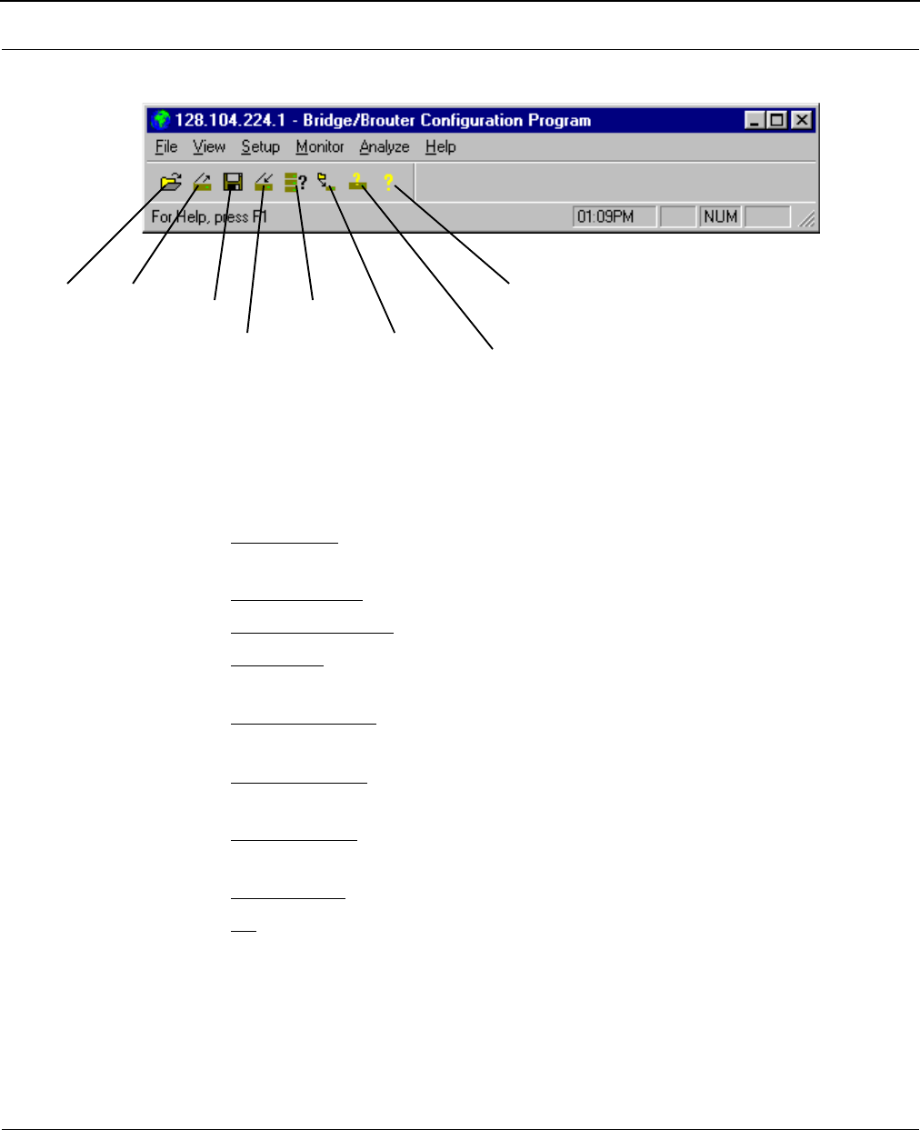
The Toolbar
Note: The functions on the toolbar can also be accessed from the menus on the Configurator
(i.e., Save can be accessed from the File menu).
The Menu Bar
•The File Menu - This is the most common menu and is used to perform the following
functions:
•Open Config File - This opens a configuration file from disk.
•Open Remote Config - This opens the configuration file directly from a remote device.
•Save Config - This saves the configuration you are working on to the place where you
opened it.
•Save Config File as - This saves the current configuration into a file on disk. This file will
have the extension .CNF.
•Import Config File - This opens a configuration file from disk. This function is used when
you are going to save the configuration from disk to a remote IDU.
•Upload Software - This enables you to load a raw and unconfigured binary file to the IDU.
This is done only in the event that the IDU's firmware has been damaged.
•Reboot Remote - This is used to reboot a IDU from a remote location.
•Exit - This closes the SPEEDLAN Configurator.
Open Open Save
Save
Select
Remote
Remote
Device Upload
Software System
Information
Help

SPEEDLAN 8500 Series Installation and Operation User Guide
Overview of Configurator 4-5
Quick Overview of Other Menus
•View Menu - This menu is used to change the display of the Configurator's various items.
•Setup Menu - This menu is used to modify all aspects of the IDU.
•Monitor Menu - This menu is used to monitor the IDU's performance and monitor another
IDU.
•Analyze Menu - This menu is used to select another IDU and perform various tests (i.e.,
interval test, wireless link test, or antenna alignment test)
•Help Menu - This menu is used to troubleshoot questions pertaining to the SPEEDLAN
Configurator.

4-6 Overview of Configurator
SPEEDLAN 8500 Series Installation and Operation User Guide
Notes:___________________________________________________
______________________________________________________
______________________________________________________
______________________________________________________
______________________________________________________
______________________________________________________
______________________________________________________
______________________________________________________
______________________________________________________
______________________________________________________
______________________________________________________
______________________________________________________
______________________________________________________
______________________________________________________
______________________________________________________
______________________________________________________
______________________________________________________
______________________________________________________
______________________________________________________
______________________________________________________
______________________________________________________
______________________________________________________
______________________________________________________

Chapter 5
Configuring SPEEDLAN
SPEEDLAN 8500 Series Installation and Operation User Guide
5-2 Configuring SPEEDLAN
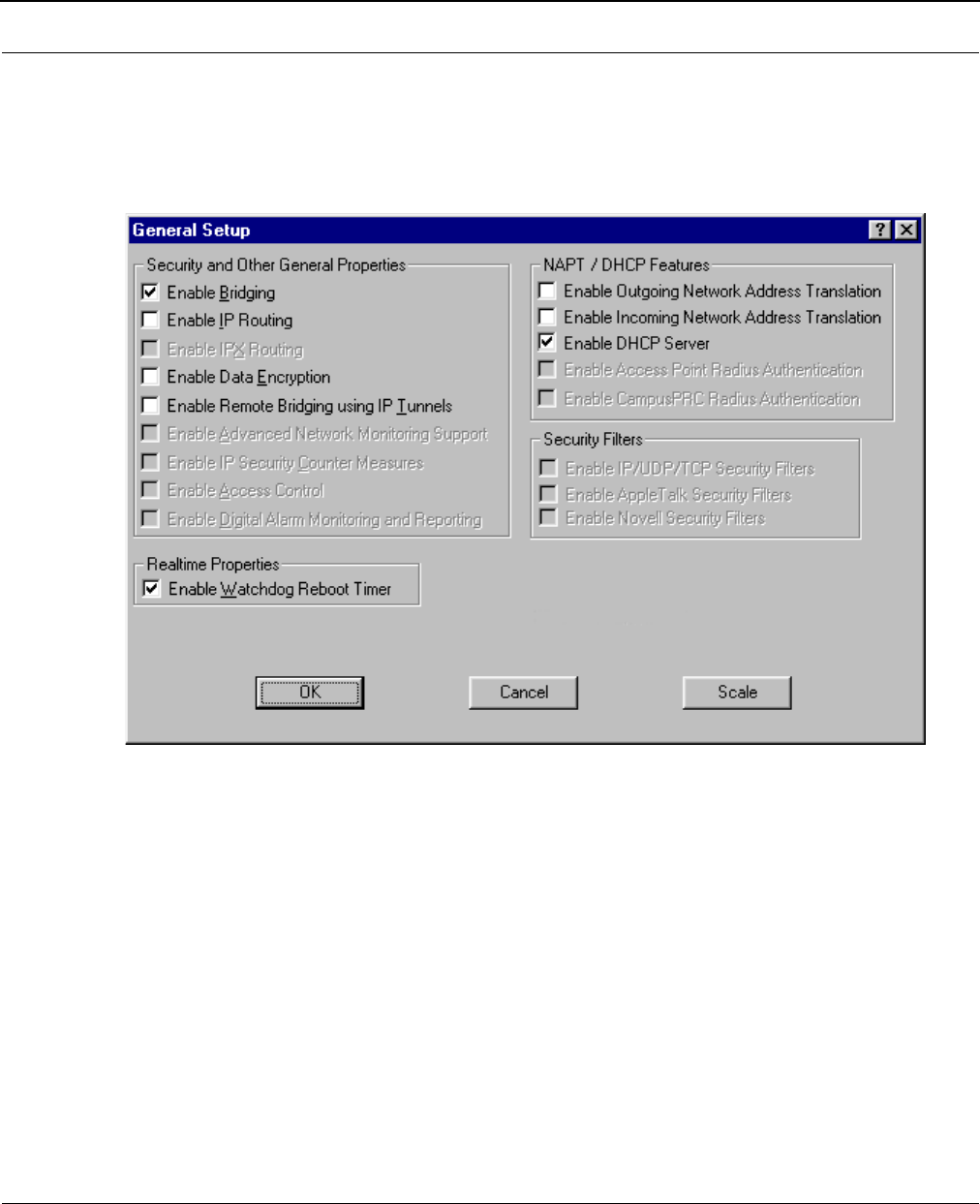
General Setup
This dialog box activates the features to configure your IDUs. To select this dialog box, choose
General Setup from the Setup menu of the SPEEDLAN Configurator. Select the appropriate check
boxes as described below:
•Enable Bridging
The transparent bridging function will be enabled when this is item is selected. If you want
the IDUs to perform the bridging function, you must select this check box. When bridging is
enabled, the IDU Setup dialog box will be accessible. Bridging should be enabled for nearly
all applications of the IDU. The default is ON.
• Enable IP Routing
The transparent routing function will be enabled when this is item is selected. IP Routing will
work properly only if the routes are set up in the IP Route dialog box. If the routes are not
set up properly before you save the configuration, the router will become
inoperable. The default is OFF.

SPEEDLAN 8500 Series Installation and Operation User Guide
Configuring SPEEDLAN 5-3
• Enable Data Encryption
This optional feature allows you to encrypt wireless data transmissions on top of the
encryption provided by the radio. It provides 56-bit DES encryption. It is not shipped
standard as part of the IDU. If you did not purchase it when you originally bought the IDU,
it can be purchased later as a software upgrade. Data encryption is disabled by default.
Select the box labeled Enable Encryption to enable the encryption features. You will still
need to define at least one encryption key before your wireless traffic will be transmitted
using wireless data encryption. To do this, return to the drop-down menu presented when
you click on Setup. Now you will see a Data Encryption Setup item added to the menu list.
Select Data Encryption Setup. Click the DES Encryption button and enter an 8 digit
alhpanumeric string in the range of "a-z", "A-Z", and "0-9".
Examples:
Alphanumeric: a5F2z4wK
Warning: This setting must be set to the same value for the IDUs that will be communicating
together. Failure to set them to the same value will prevent any communications from
taking place. For example, in order to use a multipoint link, you must use the same
Encryption setting on the base station and on the CPE IDU.
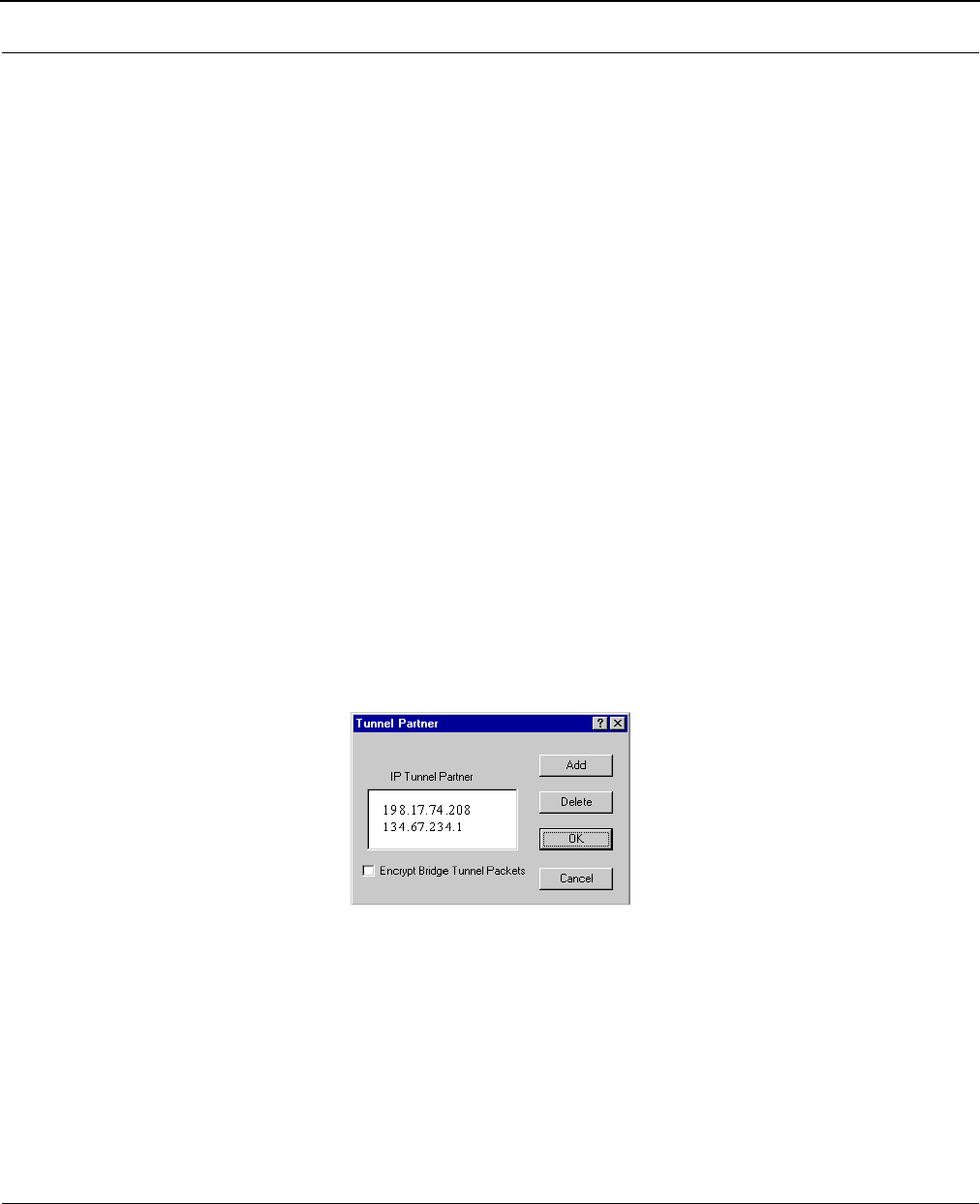
•Enable Remote Bridging using IP Tunnels
SPEEDLAN IDUs support a special feature which will enable Ethernet packets of any
protocol type to be encapsulated in IP packets and sent to other IDUs (purchased from
Wave Wireless) for de-encapsulation. This method can be used to setup virtual Ethernet
LANs between several points using an IP network as the transport layer.
•Enable Advanced Network Monitoring Support
This option is not available at this time.
•Enable IP Security Counter Measures
This option is not available at this time.
•Enable Access Control
This option is not available at this time.
•Enable Digital Alarm Monitoring and Reporting
This option is not available at this time.
•*Enable Outgoing Network Address Translation
This option enables a company to map the private network’s IP address into one or more
global network IP addresses. This means outsiders will only view the single (or more if desig-
nated) IP network address assigned for global viewing on the Internet. For more informa-
tion, see Part III - Setting Up NAT, page 7-20.

SPEEDLAN 8500 Series Installation and Operation User Guide
5-4 Configuring SPEEDLAN
•*Enable Incoming Network Address Translation
This option enables a company to unmap public network IP addresses into network IP
addresses. For more information, see Part III - Setting Up NAT, page 7-20.
•*Enable DHCP Server
This option enables the DHCP Server on the SPEEDLAN. For more information, see Part III -
Setting Up NAT, page 7-20.
•Enable Access Point Radius Authentication
This option is not available at this time
•Enable SectorPRC Radius Authentication
This option is not available at this time.
•Enable IP/UDP/TCP Security Filters
This option is not available at this time.
•Enable AppleTalk Security Filters
This option is not available at this time.
•Enable Novell Security Filters
This option is not available at this time.
• Enable Watchdog Reboot Timer
This feature instructs the IDU to reboot in the event that the IDU fails to receive any incom-
ing packets, from any port, for a period of 10 minutes. The IDU will assume an error has
occurred and will reboot. If, after the IDU reboots, it does not receive an incoming hello sig-
nal, the IDU will listen for the hello signal until the user reboots the IDU manually. The
Watchdog will recognize when a signal has been re-established and will reset the timer
accordingly.
SPEEDLAN 8500 Series Installation and Operation User Guide
Configuring SPEEDLAN 5-5
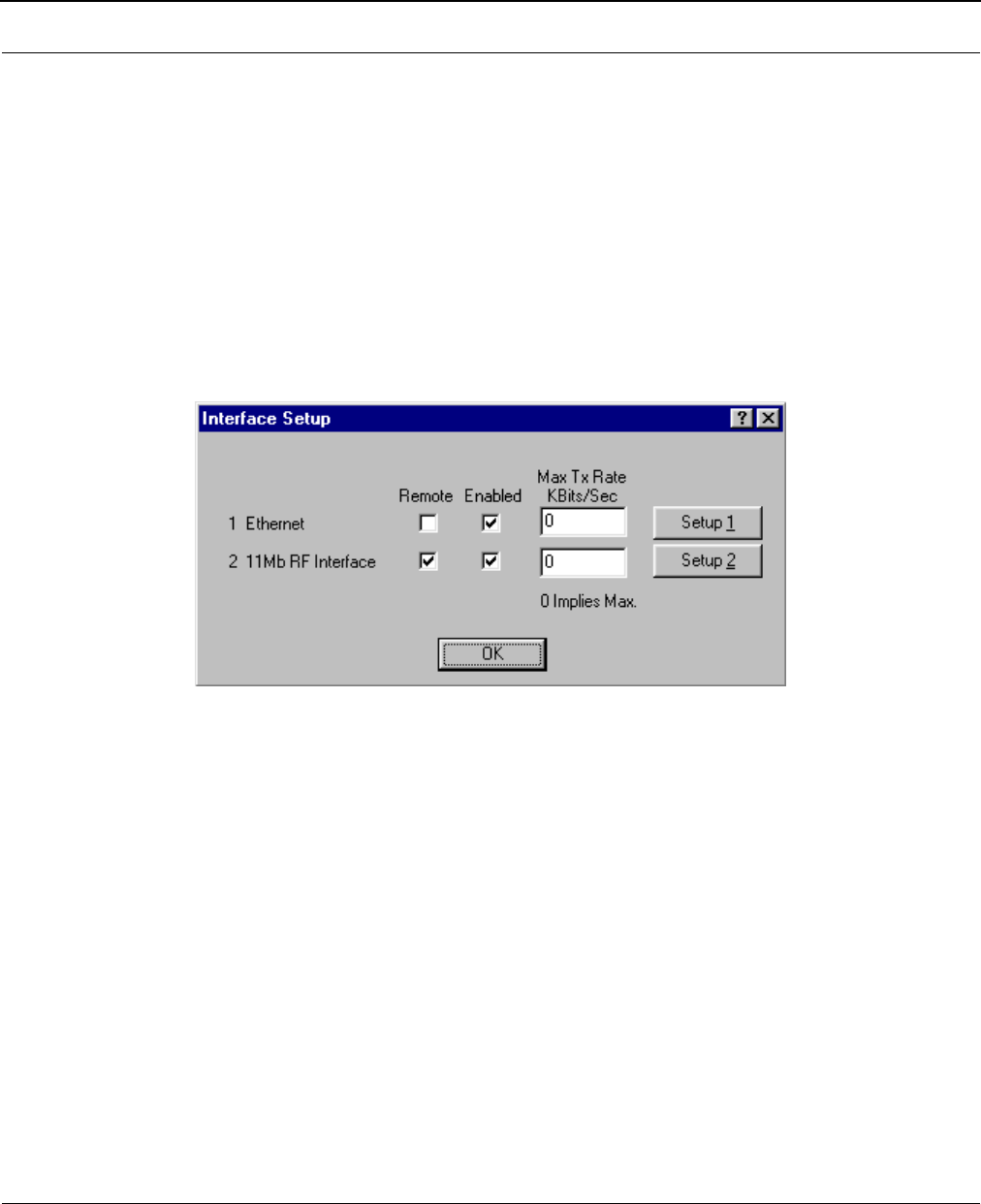
Interface & Advanced Interface Setup
Interface Setup
To set up the basic interface, choose Interface Setup from the Setup menu on the SPEEDLAN
Configurator. The interfaces that are installed in your IDU will be represented on this dialog box. The
Remote check box is used to designate which interfaces will be considered local and remote. The
local interface is considered to be the interface that connects directly to the local LAN with
respect to the IDU. The remote interface is considered to be the interface that connects with
the remote LAN. The set up buttons are used to access the portion of the configuration which
controls how the individual interfaces are configured.
SPEEDLAN 8500 Series Installation and Operation User Guide
5-6 Configuring SPEEDLAN
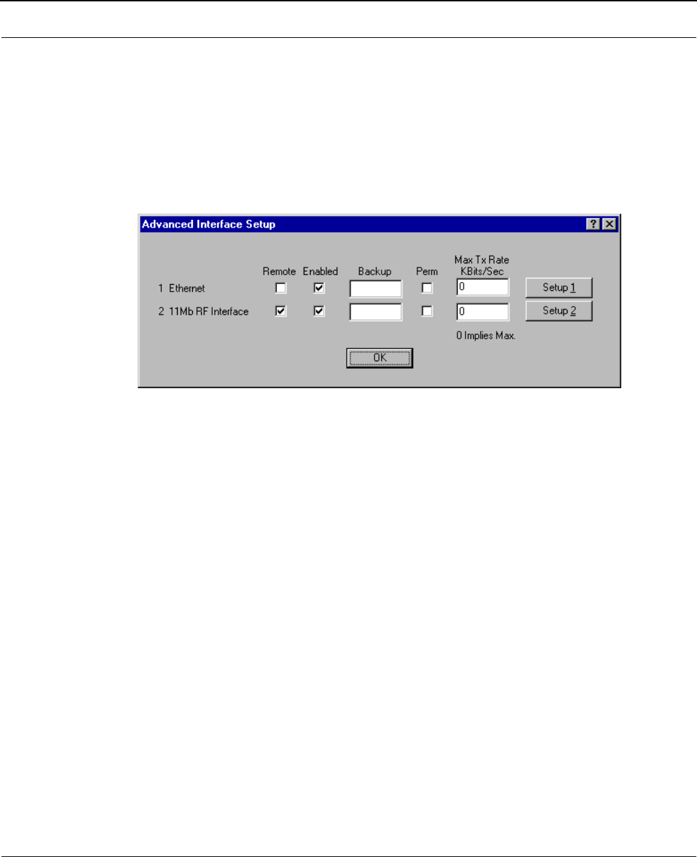
Advanced Interface Setup
To set up the advanced interface, choose Advanced Interface Setup from the Setup menu on the
SPEEDLAN Configurator. The Advanced Interface Setup contains a few more advanced settings, but
they are set up in the same manner. Note that the Max Tx rate is available on both the Interface
Setup and Advanced Interface Setup. Max Tx Rate is useful to ISPs that want to regulate the
maximum bandwidth provided to each customer. These settings should not be changed without the
assistance of a Wave Wireless Networking Technical Support Engineer.
The Setup Buttons
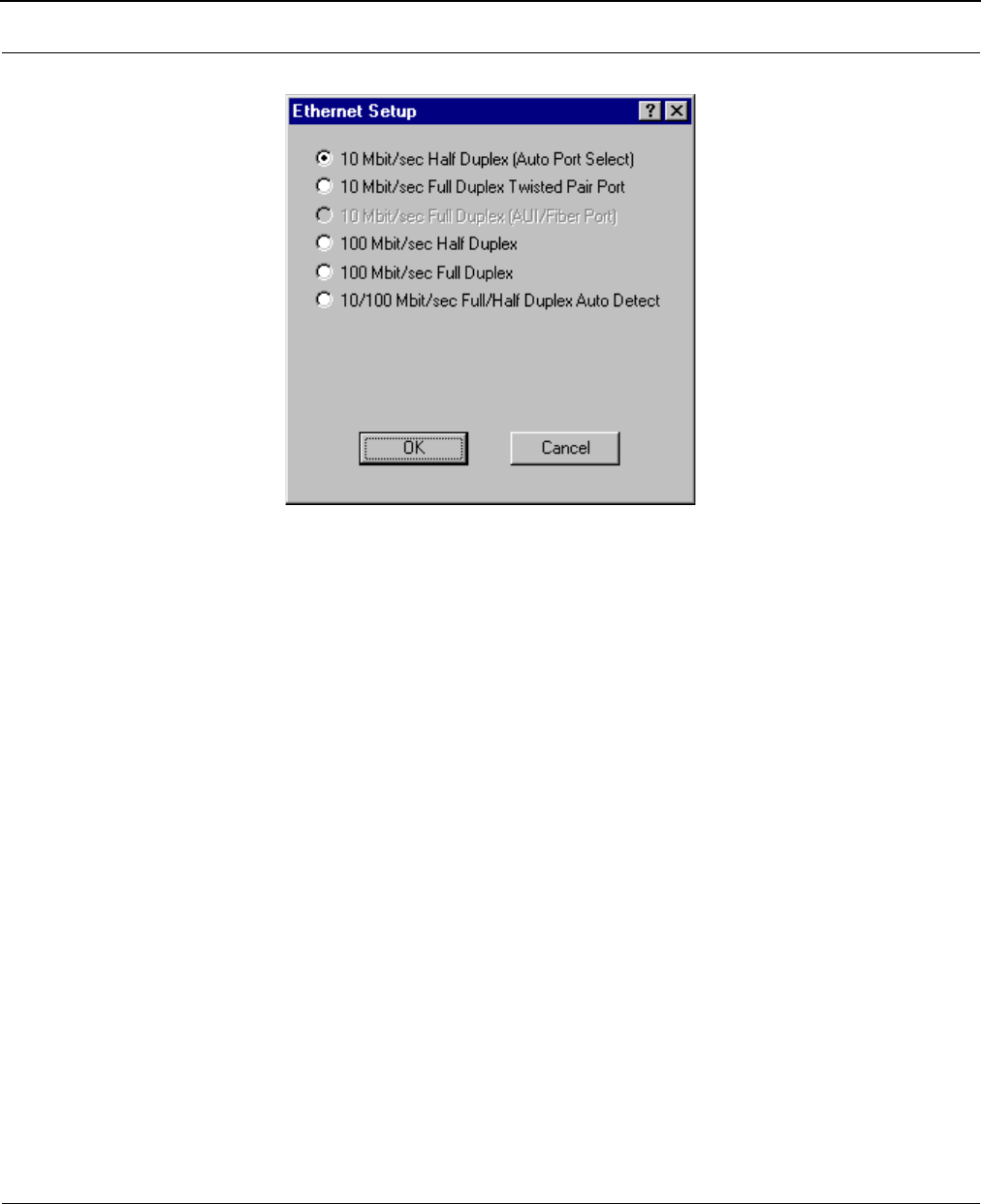
Setup 1 Button - Ethernet Setup
To modify the Ethernet Setup, click the Setup 1 button on the Interface Setup or Advanced Interface
Setup dialog box. SPEEDLAN IDUs come standard with a 10/100 Base-T interface to connect to
your wired network. Although the interface is capable of operating at both 10 Mbps and 100 Mbps,
it does not use autosensing or autoswitching functionality. The default setting is for 10 Mbps half-
duplex operation. If you want to connect your IDUs to a 100 Mbps port, the Ethernet interface can
be manually switched to 100 Mbps in this portion of the setup.
The interface also supports full-duplex operation when connected to either a 10 or 100 Mbps LAN
port. The default setting is for half-duplex. The interface can be configured to operate in the full-
duplex mode by selecting it on this dialog box.
SPEEDLAN 8500 Series Installation and Operation User Guide
Configuring SPEEDLAN 5-7
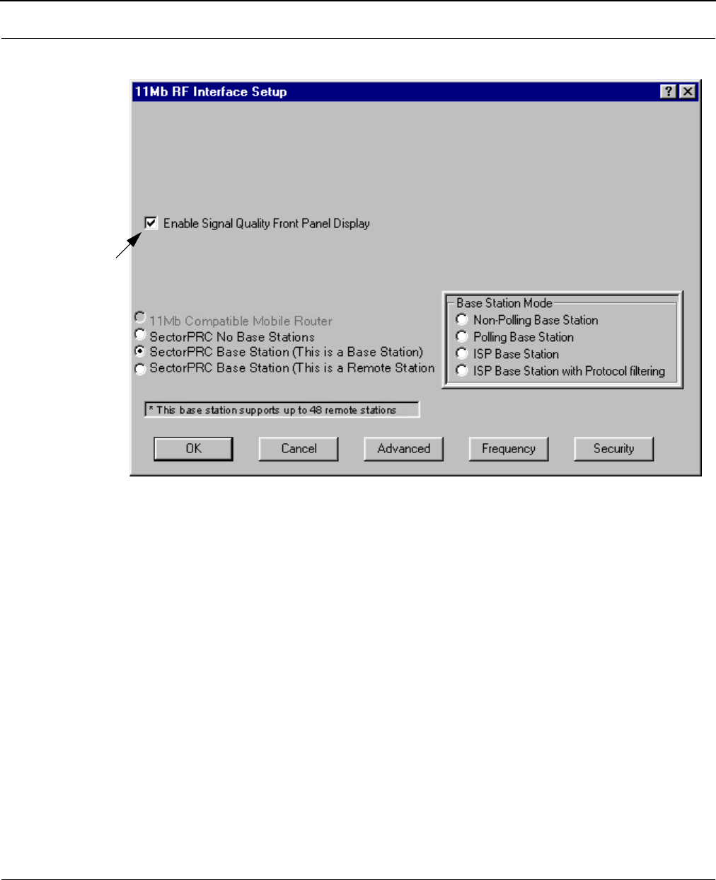
Setup 2 Button - 11 Mb RF Interface Setup
To modify the 11 Mb RF Interface Setup, click the Setup 2 button on the Interface Setup or
Advanced Interface Setup dialog box. This dialog box displays the configuration settings that control
the individual interfaces and how they communicate with each other. On the next page, you will find
a description of the settings, as well as how they affect the IDU's performance of the interfaces.
Note: Clicking the Setup buttons (1 and 2) on the Interface & Advanced Interface Setup dia-
log box will open the Setup dialog box (for the interface selected).
SPEEDLAN 8500 Series Installation and Operation User Guide
5-8 Configuring SPEEDLAN
Transport Methods
The industry compatible method of transmitting and receiving data over wireless networks will cause
data packets to frequently be lost. This is due to the fact that a wireless network does not have the
ability to detect collisions like a wired Ethernet network. On an Ethernet network, collisions can be
detected by the hardware and are automatically retransmitted. Ethernet is referred to as CSMA/CD
(Carrier Sense Multiple Access with Collision Detection). Wireless networks are CSMA/CA (Carrier
Sense Multiple Access with Collision Avoidance). Collisions cannot be detected because wireless
cannot receive and transmit at the same time. This means IDUs are not able to listen for collisions. A
IDU that is operating properly in a point-to-point network will loose, due to collisions, less than 1%
of the transmitted packets. This packet loss is not normally a problem with protocols such as Novell
IPX (without the Burst Mode NLM), but may cause networks using most other protocols to experience
poor performance. SectorPRC helps to alleviate this problem by placing multiple packets into one
larger packet, which saves bandwidth by eliminating the extra overhead. The transport methods are
described:
This actually
controls the "Link
Integrity" lights on
the front panel of
the IDU, and it is
turned ON by
default. Wave
W
ireless highly
recommends that
you leave it
enabled.
SPEEDLAN 8500 Series Installation and Operation User Guide
Configuring SPEEDLAN 5-9
•SectorPRC Mode (No Base Station/IDU)
This method of transportation is used only for point-to-point links. If any of the IDUs are
unable to see each other, a base station must be used to repeat traffic from one IDU to next
IDU in line. This point-to-point mode utilizes SectorPRC packet bundling, which reduces the
amount of overhead caused by sending smaller individual packets across the wireless
network. This greatly improves the performance of the connection.
•SectorPRC Mode (This is a Non-Polling Base Station/IDU)
This setting should be used if this is the only base station in the wireless network cell.
SPEEDLAN has a special mode where one wireless IDU can be configured as a base station
and each additional wireless node is setup as a CPE IDU. In this configuration the only
requirement is that each SPEEDLAN CPE be able to communicate directly with the
SPEEDLAN base station. The SPEEDLAN base station is responsible for repeating packets
that need to travel between the SPEEDLAN CPE. The Non-Polling Base does not allocate
dynamically bandwidth to each remote IDU.
The performance of this approach is greatly improved if the SPEEDLAN base station is connected to
the heaviest network or network server.
•SectorPRC Mode (This is a Polling Base Station/IDU)
This is the recommended mode of operation for a wireless base station. When the number
of CPE exceed 3 or 4, the non-polling base station may not be able to keep up with the
wireless traffic that needs to be forwarded. The polling base station alleviates this problem
by continuously communicating with every SPEEDLAN CPE in its cell. It is also responsible
for dynamically assigning how much bandwidth is allocated to each remote site based on
the network traffic load.
This greatly improves the performance of a SPEEDLAN base station wireless network cell. As the
number of SPEEDLAN CPE IDUs increase, the importance of a polling base station increases and
efficiency is proportionately improved.
•SectorPRC (This is a Remote Station/IDU)
This is the configuration required for remote IDUs that will be installed as CPE into a multi-
point wireless network (SPEEDLAN CPE). In this mode, a SPEEDLAN CPE will only communi-
cate with a base station. This mode cannot be used for point-to-point links.
TIP
SPEEDLAN 8500 Series Installation and Operation User Guide
5-10 Configuring SPEEDLAN
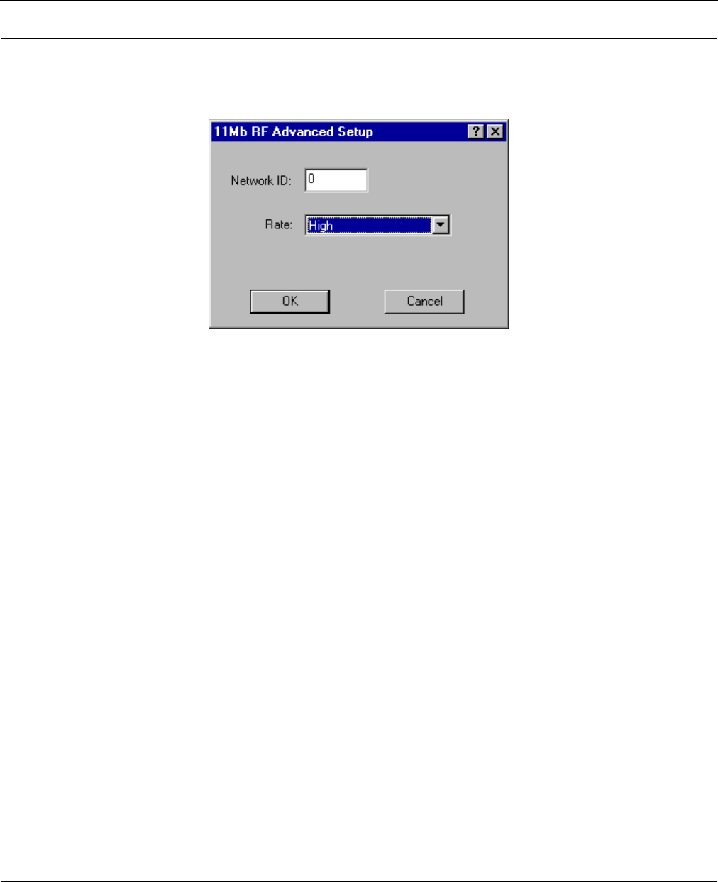
Advanced Button - 11 Mb RF Interface Setup
The Advanced button is located to the left of the Frequency button. Clicking this button will open a
new dialog box that allows you to change the Network ID and rate of the interface.
•Network ID
The Network ID is a security setting that allows the IDU to reject packets from other wireless
IDUs in the area. Although the bridging or routing table would reject the packet once it was
processed, the Network ID allows the IDU to reject the packet with less processing. This
improves the performance of the IDUs in installations where many wireless IDUs are co-
located in the same area or where other organizations may be running wireless IDUs of
their own. The default setting is 0 and the valid range is 0 to 15.
This setting must be set to the same value for the IDUs that will be communicating together. Failure
to set them to the same value will prevent any communications from taking place. For example, in
order to use a multipoint link, you must use the same Network ID setting on the base station and on
each CPE IDU.
•Rate
This setting refers to the RF data rate. The SPEEDLAN 11 Mbps radios have four data rates
that can be used:
•High
This is the full 11 Mbps data rate. The interface default to this value and it is recom-
mended that you operate using it for most installations. The receiver sensitivity of the
radio with this setting is -82 dBm.
•Medium
This setting limits the card to providing 5.5 Mbps of bandwidth. The receiver sensitivity
of the radio with this setting is -87 dBm.
SPEEDLAN 8500 Series Installation and Operation User Guide
Configuring SPEEDLAN 5-11
•Standard
This setting limits the card by providing 2 Mbps of bandwidth. The receiver sensitivity of
the radio with this setting is -91 dBm.
•Low
This setting limits the card by providing 1 Mbps of bandwidth. The receiver sensitivity of
the radio with this setting is -94 dBm.
Warning: This setting must be set to the same value for the IDUs that will be communicating
together. Failure to set them to the same value will prevent any communications from
taking place.
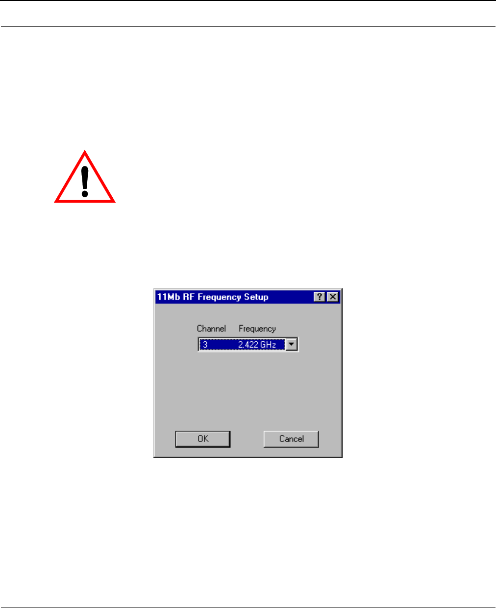
Frequency Button - 11 Mb Frequency Setup
The Frequency button is located to the right of the Advanced button. Clicking this button will open a
new dialog box that allows you to change the operating frequency of the interface. All of the IDUs
expected to communicate with this device should be configured with the same frequency.
SPEEDLAN 8500 Series Installation and Operation User Guide
5-12 Configuring SPEEDLAN
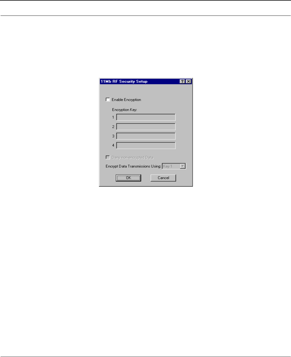
Security Button - 11 Mb RF Security Setup
The Security button is located to the right of the Frequency button. Clicking this button will open a
new dialog box that allows you to change the security options of the interface. These settings are
used to encrypt data that will be transmitted by the 11 Mb RF port and also to decrypt data that is
received by 11 Mb RF port. You may define up to 4 encryption keys to be used for decrypting
incoming data and one key for encrypting outgoing data.
Check the box labeled Enable Encryption to enable the encryption features. You will still need to
define at least one encryption key before your wireless traffic will be transmitted using wireless data
encryption.
The Encryption Key can be defined using either:
•For silver cards - Five alphanumeric characters within the "a-z", "A-Z" and "0-9" range.
•For gold cards - 13 alphanumeric characters within the "a-z", "A-Z" and "0-9" range.
Note: The alphabetical characters that you entered are "case-sensitive". For Example: Silver card users
would enter "Secu1"; and Gold card users would enter "Security Key1".
Write down the values you enter as Encryption Keys and store them in a secure place. The values you
enter will only be visible when they are entered for the first time. Each time this option is displayed
after the initial setup, the values will appear only as "xxxxxxxxxx" .

SPEEDLAN 8500 Series Installation and Operation User Guide
Configuring SPEEDLAN 5-13
Warning: This setting must be set to the same value for the IDUs that will be communicating
together. Failure to set them to the same value will prevent any communications from
taking place. For example, in order to use a multipoint link, you must use the same
Encryption setting on the base station and on the CPE IDU.
There is also an option to Deny non-encrypted Data. This feature is disabled by default and is
designed primarily for multipoint SPEEDLAN installations where it may not be necessary to run using
data encryption at all locations. If you enable this option, any data received by this IDU will not be
passed to the wired network interface.

SPEEDLAN 8500 Series Installation and Operation User Guide
5-14 Configuring SPEEDLAN
Notes:___________________________________________________
________________________________________________________
________________________________________________________
________________________________________________________
________________________________________________________
________________________________________________________
________________________________________________________
________________________________________________________
________________________________________________________
________________________________________________________
________________________________________________________
________________________________________________________
________________________________________________________
________________________________________________________
________________________________________________________
________________________________________________________
________________________________________________________
________________________________________________________
________________________________________________________
________________________________________________________
________________________________________________________
________________________________________________________
________________________________________________________

Chapter 6
Bridging Setup
SPEEDLAN 8500 Series Installation and Operation User Guide
6-2 Bridging Setup
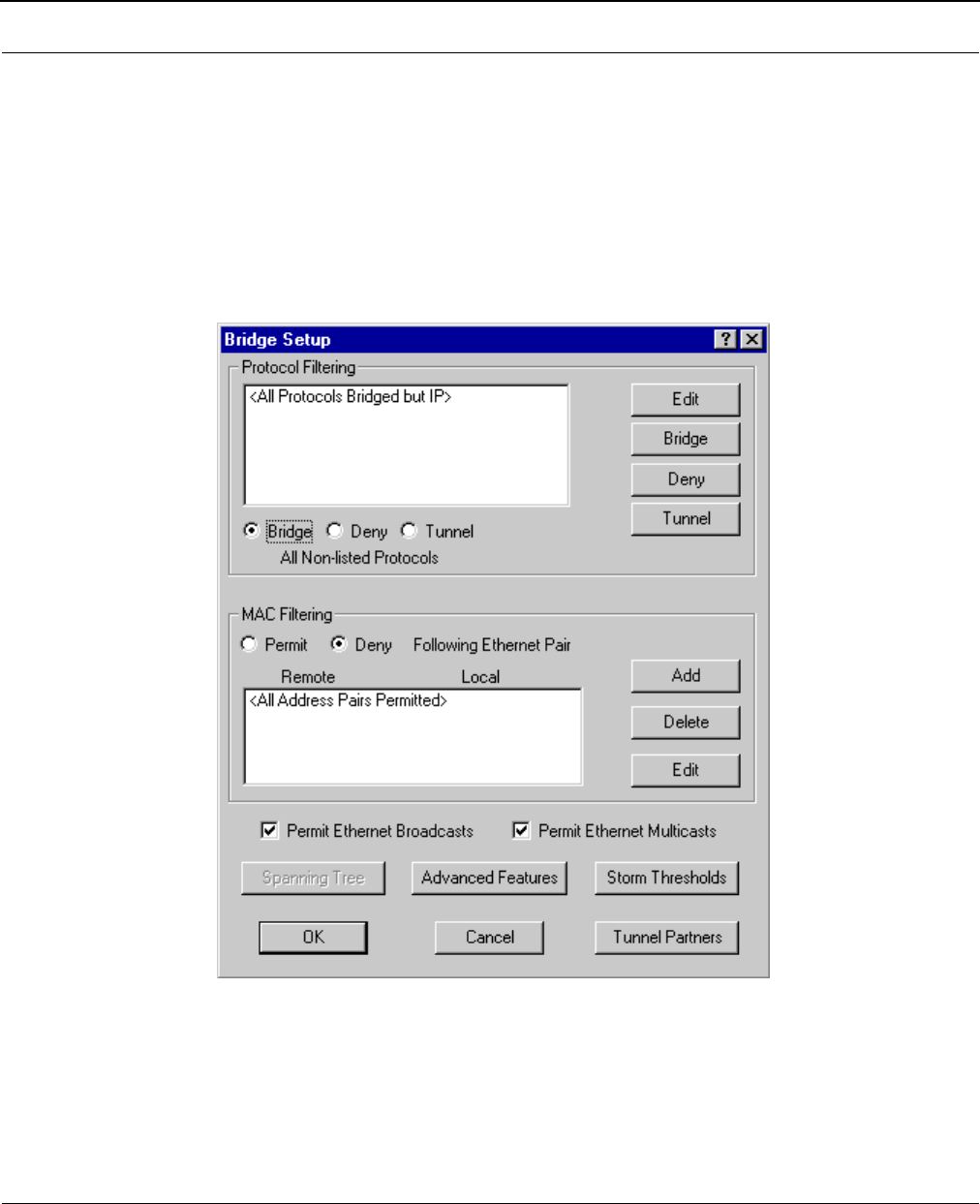
IDU Setup
Each SPEEDLAN IDU contains an IEEE 802.3 MAC-layer bridging engine. The IDU can be
configured to filter or pass any 802.3 frame type protocols, including Novell IPX, TCP/IP, AppleTalk,
etc. The IDU can also be configured to filter packets by their destination and origin. This is done
using the unique MAC (Media Access Control) addresses that all network interface devices have
assigned to them at the factory. IDU Setup is accessed from the main Setup menu of the SPEEDLAN
Configurator.
SPEEDLAN 8500 Series Installation and Operation User Guide
Bridging Setup 6-3
Protocol Filtering
By default, the IDU is configured to pass all network protocols. When you click Edit, you will be
presented with a list of protocols which you can select for filtering. After selecting the protocols,
highlight them on this dialog box. Then, click IDU or Deny to determine how each protocol will be
treated. The radio buttons in the Protocol Filtering box determine how unselected protocols are
treated.
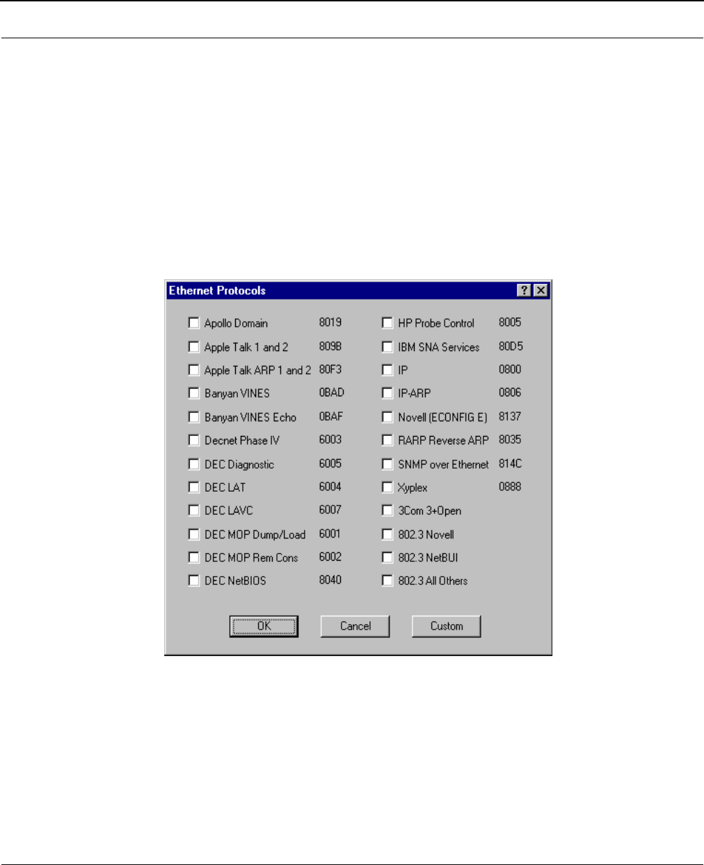
Edit Button - Ethernet Protocols
Some common Ethernet protocols and their associated ID numbers have been placed in this table.
Select one from this list if you want to set a filter for it.
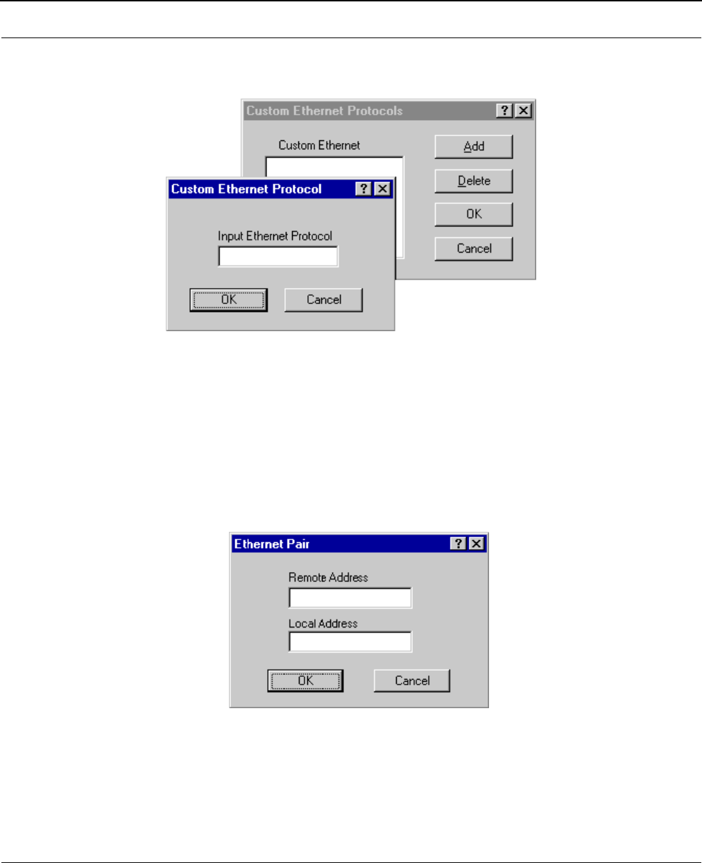
SPEEDLAN 8500 Series Installation and Operation User Guide
6-4 Bridging Setup
If the protocol you want to filter is not presented here, click Custom, Add and enter the hex ID for
that protocol.
MAC Filtering
By default, the IDU is configured to pass all traffic between all MAC-Address pairs. To add an
address pair into the filter, click Add on the MAC Filtering box. First, enter the Remote Address,
which will be the MAC Address that resides on the remote side of the IDU. Second, enter the Local
Address, which will be the MAC Address that resides on the local side of your connection. The local
and remote interfaces are defined on either the Interface Setup or Advanced Interface Setup dialog
box. It is recommended that you define the RF port as the Remote Interface (default setting).
SPEEDLAN 8500 Series Installation and Operation User Guide
Bridging Setup 6-5
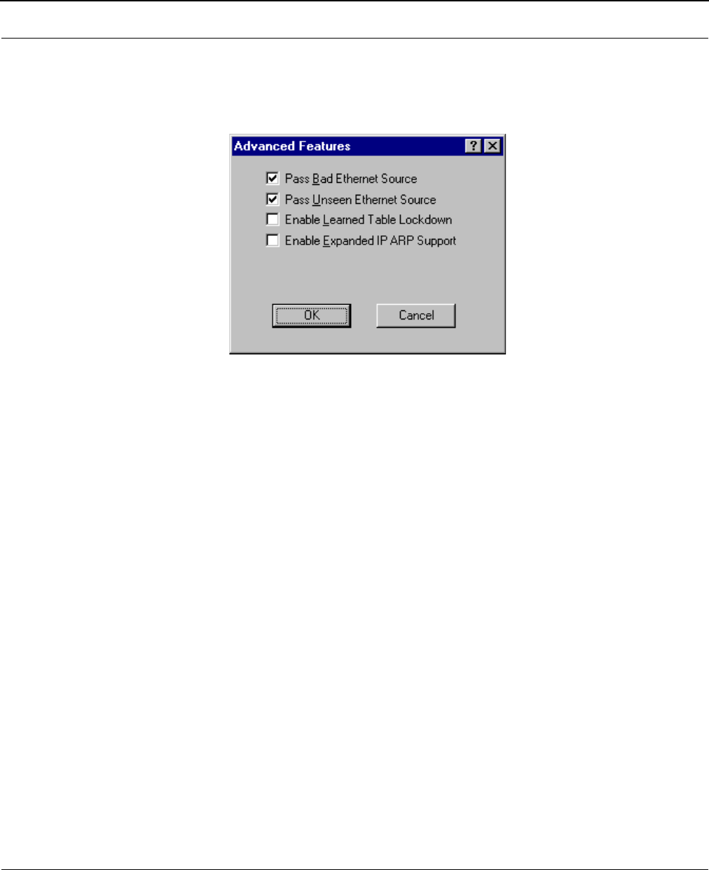
Advanced Features Button
Clicking Advanced displays this dialog box. Select the appropriate check box for your network. The
check boxes are described below:
•Pass Bad Ethernet Source
The standard Ethernet IDUs we have tested will pass Ethernet packets with a broadcast or
multicast address as their source (i.e., packets with their first bit set to 1). The Ethernet
specification for Transparent (i.e. Non-Source-Routing) IDUs does not allow these types of
packets, which are considered bad packets. Our studies have shown that a common failure
mode of many Ethernet interfaces and networking software is to transmit packets like these.
If you do not need to permit Source-Routing packets, we suggest that you deny these
packets. The default setting is selected to permit these packets.
• Pass Unseen Ethernet Source
Standard Ethernet IDUs will always forward packets with destination addresses that have not
been learned (i.e., have not previously been seen as a source address of a packet). This
characteristic is needed in order for the Ethernet IDU to operate correctly. The downside to
this, as our studies have shown, is the failure mode of many Ethernet interface cards will
send out erroneous packets with good CRCs but with random Ethernet destination and
source addresses. Standard IDUs will permit these erroneous packets because they have not
"learned" the random destination, and then add this packet's random source address to
their finite learned table. This situation is not uncommon and can greatly hinder the
operation of standard IDUs. If you choose to deny unlearned packets, the IDU will not
forward unicast packets to Ethernet addresses that have not already been seen as a source
address. This scheme works for most protocols because it relies on the characteristics of
most upper-layer protocols to transmit ARP requests or hello packets. After careful testing
and consideration, only qualified network engineers should select the Deny option.
The default value for this setting is selected.

SPEEDLAN 8500 Series Installation and Operation User Guide
6-6 Bridging Setup
•Enable Learned-Table Lockdown
A standard IDU watches the source address of each packet it receives on any of its
interfaces. As new addresses are seen, entries are added to the learned table that con-
tains each source address and the interface number that address was received on. If a
source address is later seen on a different interface, the IDU will immediately change
the interface number in the learned-table entry. This condition could happen in a net-
work that is operating well if someone moved a computer to a different part of the net-
work. This could also happen if someone was trying to capture network packets by
fooling the IDU. Enabling learned-table lockdown will prevent the interface number
from being changed once the source address has been seen. A standard IDU will also
time-out the learned-table records every 10 minutes. If learned-table lockdown is
enabled, these records will not be timed out. Once a record is learned, it will not
change or be deleted until either the IDU reboots or the learned table become com-
pletely filled and needs to be reset. (NOTE: A typical SPEEDLAN learned table can con-
tain over 12,000 records.) The default value for this setting is disabled.
•Enable Expanded IP ARP Support
Enabling this feature will cause the IDU to also watch the IP/ARP packets that occur on
the network. The SPEEDLAN 8500 IDUs take no action in response to IP/ARP packets
(since that is the role of an IP router) except to add the IP address to its IP/ARP table.
This feature is helpful on an IP network because it will build a database of MAC-layer-
address-to-IP address pairs. An SNMP monitoring program, such as the SPEEDLAN
Configurator, can at any time extract this information. NOTE: 1) The IP/ARP table is
never timed out in this mode. 2) This feature is not available if the IDU is routing IP. The
default value for this setting is disabled.
•Permit Ethernet Broadcasts
Standard Ethernet IDUs will always forward broadcast packets. Many protocols do not use
broadcasts (e.g., AppleTalk Phase II, DECnet, and others). However, IP/ARP does use
broadcasts. If you do not use IP or any other protocol that requires broadcasts, you can
deny them. Shutting off broadcast packets will reduce the traffic being sent across your
wireless network link. This will also greatly reduce the number of interrupts that each
computer connected to your network experiences. Networks with a high number of
broadcasts will slow down the processing of all attached computers, even those that aren't
using the network.
•Permit Ethernet Multicasts
Standard Ethernet IDUs will always forward multicast packets. Some protocols do not use
multicast packets, such as TCP/IP and Novell IPX. If you do not use protocols that use
multicast packets, you can drop them by disabling multicast on the IDU. This will reduce the
traffic that is sent across the wireless network link. In addition, it reduces the number of
interrupts that each computer connected to your network experiences.
SPEEDLAN 8500 Series Installation and Operation User Guide
Bridging Setup 6-7
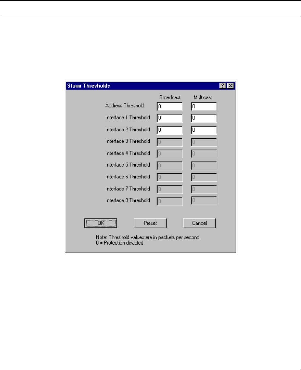
Storm Thresholds Button
Click Storm Thresholds to keep broadcast and multicast storms from spreading throughout the
network. Network storms are common and can cause IDUs, routers (IDUs), workstations, servers,
and PCs to slow down or crash. Storms occur if network equipment is configured incorrectly, if
network software is not functioning properly, or if poorly designed programs such as network games
are used. These settings are disabled by default.
•Address Threshold
This setting determines the maximum number of broadcast or multicast packets that can
occur during a one-second period before a storm condition is declared for a particular
Ethernet address (host). Once it is determined that a storm is occurring, any additional
broadcast or multicast packets from that host address will be denied until the storm is
determined to be over. The storm will be determined to be over when 30 seconds have
passed in which every one-second period has less then the stated threshold in broadcast or
multicast packets. The settings for broadcast packets and multicast packets are configured
independently.
SPEEDLAN 8500 Series Installation and Operation User Guide
6-8 Bridging Setup
•Interface Threshold
This setting determines the maximum number of broadcast or multicast packets that can
occur during a one-second period before a storm is declared for the assigned interface.
Once it is determined that a storm is occurring, any additional broadcast or multicast
packets received on that interface will be denied until the storm is determined to be over.
The storm will be determined to be over once a one-second period has occurred with no
broadcast or multicast packets received on that interface. The settings for broadcast packets
and multicast packets are configured independently.
• Preset Button
This button sets the broadcast and multicast storm thresholds to the recommended values.
These values have been determined to offer good protection without interfering with the
operation of the typical network. These values may need to be tuned for your particular
network.
Tunnel Partners Button
Click Tunnel Partners to encapsulate Ethernet packets received from the local interface in an IP/
UDP packet and then send them to one or more tunnel partners. Tunneling can be used to set up
virtual Ethernet networks. In the General Setup dialog box, if the Remote Bridging using IP
Tunnels is enabled, Tunnel Partners can be set up. This dialog box specifies the IP addresses of
each of the IDU/routers that are to participate in the tunnel group. Specify the addresses of all
the IDUs that are participating in the tunnel group but DO NOT specify the IP addresses on
this IDU.
•Encrypt IDU Tunnel Packets
If purchased, a IDU (from Wave Wireless) may contain a special software-encryption algo-
rithm that is distinct from the optional SPEEDLAN encryption chip on the IDU. If Data
Encryption is enabled on the General Setup dialog box and if an Encryption Key is set up in
the Data Encryption menu, enabling encryption here will cause all Ethernet packets trans-
mitted to tunnel partners to be encrypted and encapsulated inside IP packets. The IP packet
itself cannot be encrypted because industry-standard IP routers, like those on the Internet,
would not be able to forward the encrypted packets.
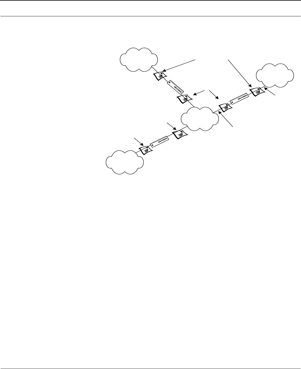
SPEEDLAN 8500 Series Installation and Operation User Guide
Bridging Setup 6-9
Generic Ethernet Tunneling
(Through an IP Network)
LAN A
LAN C
LAN B
Internet or
Campus IP
Network
Standard Ethernet Packet
Ethernet Packet
Encapsulated in IP/UDP
Ethernet Packet
Encapsulated in
IP/UDP
Standard
Ethernet Packet
Local
Interface
Rem ote Interface
The three IDUs are set up to tunnel one
or more protocols and each is a tunnel
partner to the other two IDUs. This
configuration allows LAN A, LAN B, and
LAN C to become a virtual private Ethernet
network with the Internet as the transport
mechanism for data between them. The
encapsulated data packets can be optionally
encrypted to make the virtual private
network more secure.

SPEEDLAN 8500 Series Installation and Operation User Guide
6-10 Bridging Setup
Notes:___________________________________________________
________________________________________________________
________________________________________________________
________________________________________________________
________________________________________________________
________________________________________________________
________________________________________________________
________________________________________________________
________________________________________________________
________________________________________________________
________________________________________________________
________________________________________________________
________________________________________________________
________________________________________________________
________________________________________________________
________________________________________________________
________________________________________________________
________________________________________________________
________________________________________________________
________________________________________________________
________________________________________________________
________________________________________________________
________________________________________________________
________________________________________________________
________________________________________________________
________________________________________________________
________________________________________________________
________________________________________________________
________________________________________________________
________________________________________________________

Chapter 7
Setting Up the IP Addresses
(IP Host Setup)

SPEEDLAN 8500 Series Installation and Operation User Guide
7-2 Setting Up the IP Addresses (IP Host Setup)
If you do not understand the basics of IP addressing, DHCP, or NAT, please read the next section,
Part I - Quick Overview of IP Addressing, below. Otherwise, skip to Part II - Setting Up the IP Address,
page 7-13.
Part I - Quick Overview of IP Addressing
IP Addressing is important because it tells the network how to locate the computers or network
equipment connected to it. IP addresses are given so each computer or equipment on the network
contains a unique address. In addition, network addresses and node addresses, depending on the
Class (A, B, C, etc.), contain their own unique address as well. IP addressing provides the following
information:
•Provides communication between different platforms and diverse systems
•Provides universal data transfer over large geographic distances
•Has been "adopted" as a standard in the computer industry
What is an IP address?
An IP address contains 32 bits of information, which is divided into the following:
•Two sections: the network address and the node address (also known as the host address)
•To keep it simple, lets call it four bytes (octets)
Note: Each octet contains 8 bits, which are equivalent to 1 byte. Each octet is separated by a
period (.).
The following examples show the conversion of the same IP address into several different formats:
•Decimal (130.57.30.56)
•Hexadecimal (82.39.1E.38)
•Binary (10000010.00111001.00011110.00111000).

SPEEDLAN 8500 Series Installation and Operation User Guide
Setting Up the IP Addresses (IP Host Setup) 7-3
Internet Address Classes
The first octet defines the "class" of the address, which is the only method to tell the size of the
network (how big) and where the internet address belongs. There are three main classes:
•Class A: 35.0.0.0
•Class B: 128.5.0.0
•Class C: 192.33.33.0
-non-bolded text = Part of network address
-bolded text = Part of local address (node section)
This definition is not random; it is based on the fact that routers, by reading just the first three bits of
the address field, designate which network class it belongs to. This selection simplifies the way
routers handle the messages (packets) and speed up the forwarding process.

SPEEDLAN 8500 Series Installation and Operation User Guide
7-4 Setting Up the IP Addresses (IP Host Setup)
In fact, IP defines five classes:
•Class A addresses use 8 bits (1 octet) for the network portion and 24 bits (3 octets) for the
node (or host) section of the address. This provides up to 128 networks with 16.7 million
nodes for each network.
•First byte is assigned as network address
•Remaining bytes used for node addresses
•Format: network, node, node, node
•In IP address 49.22.102.70, "49" is network address and "22.102.70" is the node
address—all machines on this network have the "49" network address assigned to them
•Maximum of 224 or 16,777,216 nodes
•Class B addresses use 16 bits (two octets) for the network portion and 16 bits for the node
(or host) section of the address. This provides up to 16, 384 networks with 64,534 nodes
for each network.
•First two bytes are assigned as network address
•Remaining bytes used for node addresses
•Format: network, network, node, node
•In IP address 130.57.30.56, "130.57" is the network address, and "30.56" is the node
address
•Maximum of 216 or a total of 65,534 nodes
•Class C addresses use 24 bits (3 octets) for the network portion and 8 bits (two octets) for
the node (or host) section of the address. This provides 16.7 million networks with 256
nodes for each network.
•First three bytes are assigned as network address
•Remaining byte used for node address
•Format: network, network, network, node
•In IP address 198.21.74.102, "198.21.74" is the network address, and "102" is the
node address
•Maximum of 28 or 254 node addresses

SPEEDLAN 8500 Series Installation and Operation User Guide
Setting Up the IP Addresses (IP Host Setup) 7-5
•Class D
•Range is 224.0.0.0 to 239.255.255.255
•Used for multicast packets (i.e., host sends out router discovery packets to learn all of
the routers on the network)
•Class E
•Range is 240.0.0.0 to 255.255.255.255
•Reserved for future use
Note: Class D & E should NOT be assigned to net assignment of IP addresses. In addition,
the first octet, 127, is reserved. In each network definition, the first node number (i.e.,
"0") is used to define the network, as well as the last number (i.e., "255"). The last num-
ber is known as the broadcast address.
Public IP addresses can be obtained from the following address:
Network Solutions
InterNIC Registration Services
505 Huntmar Park Drive
Herndon, VA 22070
hostmaster@internic.net
Note: Non-public addresses can include a network address assigned from the network
administrator or from the IP provider. Also, there is one network in each class that is
defined for private use, allowing the creation of internal networks. These addresses are
Class A: 10.0.0.0, Class B: 172.10.0.0, and Class C: 192.168.0.0.
Subnetting a Network
The increasing number of hosts and networks make impractical address blocks that are not smaller
than 245. In order keep the IP address small, so routers can manage them without changing the
whole protocol, a smaller network definition is created. This is called a subnet. Subnets are intended
to:
•Reduce network traffic
•Optimize performance
•Simplify management
•Create more effective and efficient addresses for large geographic distances

SPEEDLAN 8500 Series Installation and Operation User Guide
7-6 Setting Up the IP Addresses (IP Host Setup)
Default Subnet masks
•Class A: 255.0.0.0
•Class B: 255.255.0.0
•Class C: 255.255.255.0
Note: Subnet mask is bolded.
What is a Subnet?
Subnetting allows you to create multiple networks within one Class A, B, or C network. Each data
link (octet) contains its own unique identifier also known as the subnet. Also, each node on the same
data link must belong on the same subnet as well.
What is a Subnet Mask?
A subnet mask allows you to mask section(s) (depending on the class specified) of the octets in the
network address. Each octet used in the subnet mask is assigned to a data link. The leftover octet(s)
are assigned to the remaining nodes.
For more information on subnetting, see the example below and Diagram of Subnetting a Network,
page 7-7.
Example of Subnetting:
For example, a Class C network (255.255.255.0) contains three masked octets (255.255.255). The
last octet (0) is leftover for remaining nodes (i.e., computers).
If Router D is reading IP Addresses 195.172.3.1 (let's call this IP Address 1) and 195.172.3.64 (let's
call this IP Address 2) on this Class C network, it would send IP Address 1 to Subnet A and IP Address
2 to Subnet B. The remaining nodes in each subnet (A through D) on this network can contain up to
254 pieces of network equipment (computers, printers, fax machines, IDUs or routers, etc.).
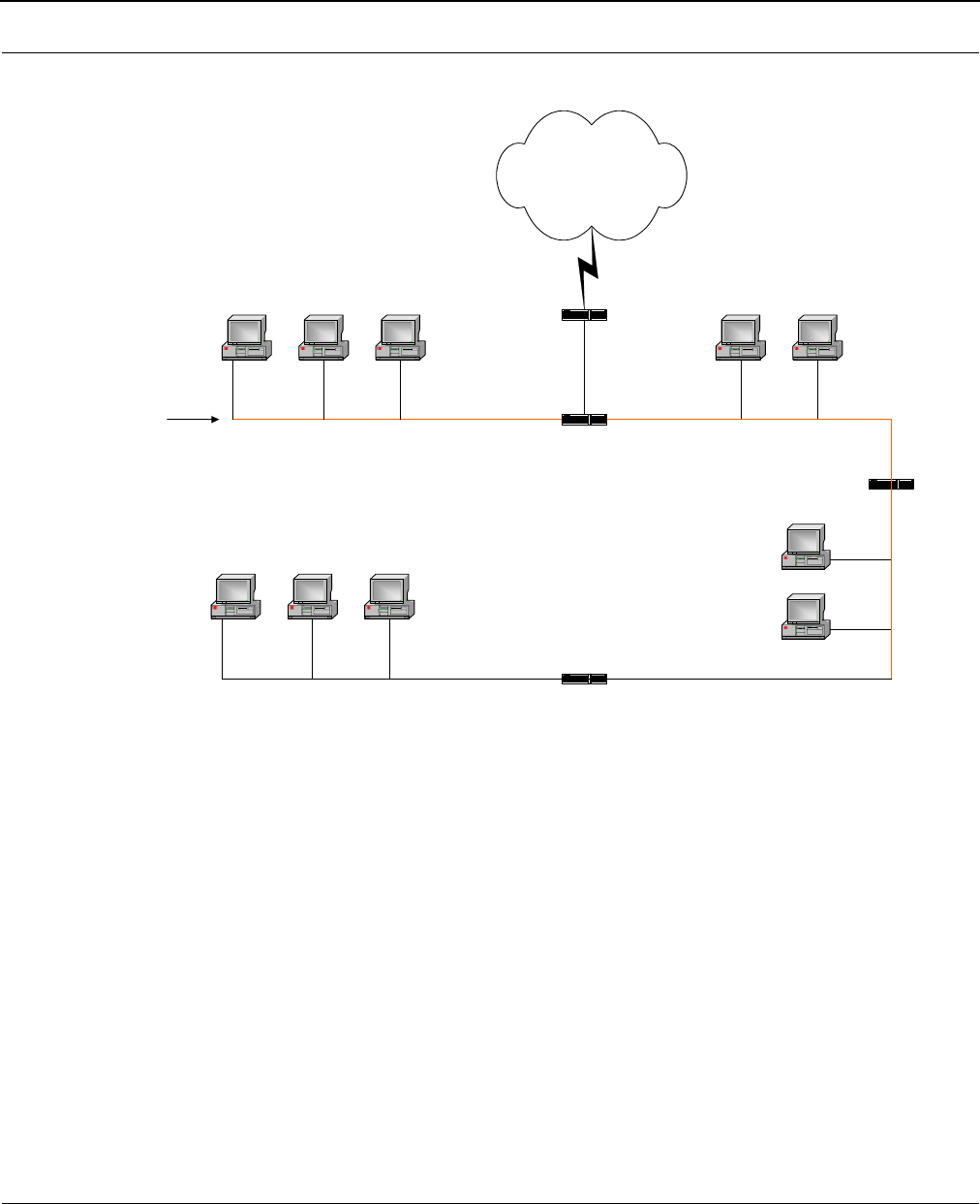
SPEEDLAN 8500 Series Installation and Operation User Guide
Setting Up the IP Addresses (IP Host Setup) 7-7
Diagram of Subnetting a Network
Still confused?
An easier method to explain this concept is to use the classic "mailing" analogy used in IP
addressing. Consider that this network, called Long Street, is four blocks long. There are 254 houses
on Long Street, and each block contains 64 houses. Houses 1 to 63 reside on Block A. Houses 64
to 127 reside on Block B. Houses 128 to 191 reside on Block C. Houses 192 to 254 reside on
Block D. Think of each block as a subnet. This means that Blocks A, B, C, and D are all part of Long
Street, which is also known as the network in this example. The mailman would organize the letters
(or IP addresses for network equipment) by creating four piles (one for each block, or subnet). As
soon as the mailman picks up pile A in his hand, he knows which block to turn on. This same
reasoning applies to piles B, C, and D as well. Router D knows exactly which subnet to transfer (or
turn) the packets to by reading its IP and subnet mask address. Note that each subnet on this
network is 255.255.255.192. Why is 192 the last octet in the subnet mask and not 64? The last
octet, 192, is the mask that allows 64 "houses" to know that the mailman (or router) is coming in
advance. The "houses" will know it's mailman "Jim" by looking at the IP number.
Internet
Router D
Router B
Router C
Computer Computer
Computer
Computer
Computer Computer Computer
Computer Computer Computer
Long Street
Subnet A
IP Address: 195.172.3.1
Subnet Mask: 255.255.255.192
Subnet B
IP Address: 195.172.3.64
Subnet Mask: 255.255.255.192
Subnet C
IP Address: 195.172.3.128
Subnet Mask: 255.255.255.192
Subnet D
IP Address: 195.172.3.192
Subnet Mask: 255.255.255.192
Router A

SPEEDLAN 8500 Series Installation and Operation User Guide
7-8 Setting Up the IP Addresses (IP Host Setup)
Note: If the network is managed by a Simple Network Management Protocol for local or
Internet access, each IDU must contain a unique IP Address. This is a benefit of static or
dynamic addressing.
How does a network administrator assign an IP address?
IP addresses are supplied by the network administrator, the ISP, or hosting company.
The two types of IP addressing—manual (static) and automatic (dynamic) addressing—are described
below.
•Manual (static) Addressing
Each device connected to the Internet must have its own unique IP address. Also, if a
computer is being used as a server, you will assign it a permanent IP address. This enables
other computers to connect to it. Static addressing is also beneficial to users that need to
maintain a "constant" connection to the Internet. This will enable users to easily access the IP
address.
•Automatic (dynamic) Addressing
A DHCP (Dynamic Host Configuration Protocol) server assigns the IP address to each
computer as the computer connects to the network. If a computer moves to a new network
(i.e., great for temporary employees or mobile users), it must be assigned a new IP address
for that network. DHCP can be used to manage these assignments automatically. DHCP is
described in further detail below.
What is DHCP?
Dynamic Host Configuration Protocol (DHCP) allows network administrators to assign dynamic IP
addresses for the period of time needed to connect to the Internet. Think of DHCP as leasing an
apartment. A prospective tenant may not need to live in an apartment for two years, maybe just a
year. Therefore, the tenant will only sign a one-year lease agreement. For example, each time a
computer is set up to connect to the Internet, the network administrator uses DHCP to automatically
assign the computer a unique IP address. That computer will give up its IP address when it is no
longer needed (when the lease has ended) allowing new a computer (or a new tenant) on the same
network to use it. This benefits educational and corporate settings where users often log on to
different computers. In this case more IP addresses outnumber computers because you can quickly
reconfigure the network if needed from a centralized location.
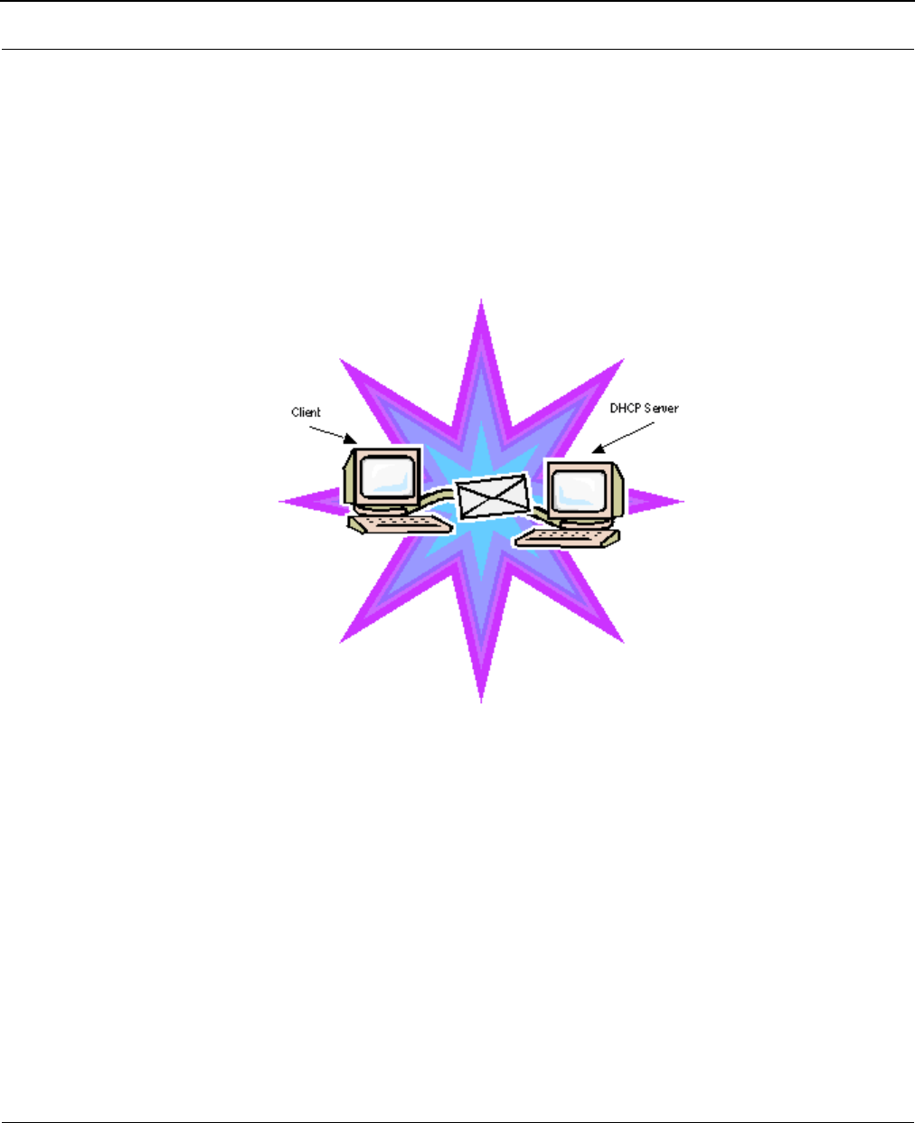
SPEEDLAN 8500 Series Installation and Operation User Guide
Setting Up the IP Addresses (IP Host Setup) 7-9
Servers that utilize DHCP resolve security issues, costly IP addressing services, and compatibility
problems. DHCP is an alternative to BOOTP, which reduces the agony of assigning static IP
addresses and also provides advanced configuration options.
Note: The figure on the next page may help you understand how DHCP assigns an IP
address.
Figure of DHCP Addressing
1The client asks DHCP server for IP address and configuration if needed.
2The DHCP server assigns an available IP address to client.
3The client takes IP address from DHCP server and requests any additional configuration
needed.
4DHCP server confirms IP address and configuration.

SPEEDLAN 8500 Series Installation and Operation User Guide
7-10 Setting Up the IP Addresses (IP Host Setup)
What is NAT?
Network Address Translation (NAT) is the conversion of an Internet Protocol address (IP address)
used within one network to a different IP address within another network. One network is designated
the inside network and the other is the outside network.
Network Address Translation (NAT) occurs when there is a translation among an Internet Protocol (IP
address) used within one network (designated as inside network) to a different IP addresses within
another network (designated as outside network). Network Address Translators (NATs) allow
companies to decrease the number of global IP addresses. This enables companies to communicate
with other devices on the Internet using a single IP address (or more than one IP address).
For example, a company can provide its clients with one IP address, allowing access to the
company's firewall only. This IP address is not a "real" address on the company's internal network, but
it is successfully translated to the correct IP location through NAT (i.e., NAT router). Therefore, the
company controls access through firewalls and provides multiple IP addresses to outside customers
without excessive limited resources, or "global" Internet IP protocols.
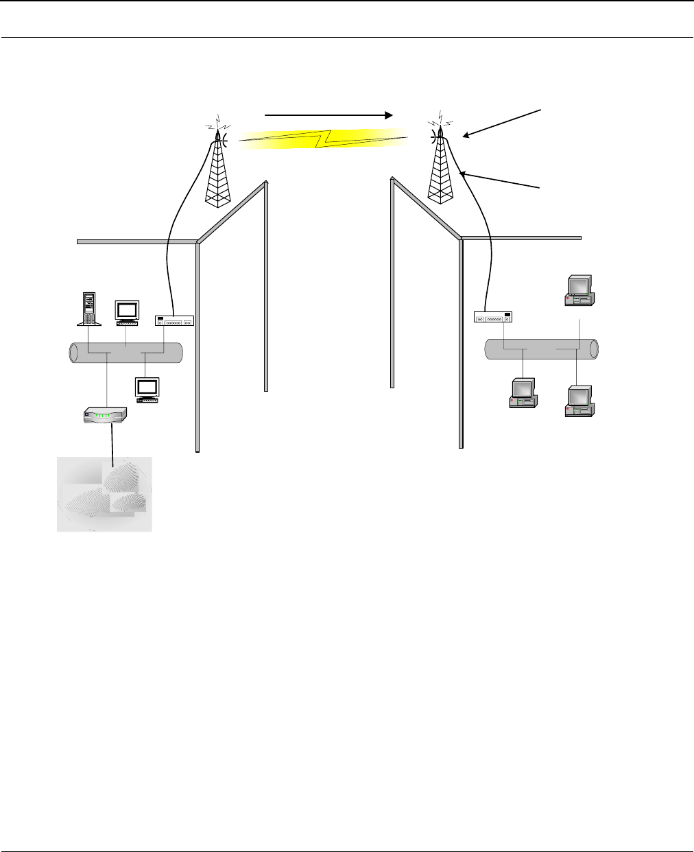
SPEEDLAN 8500 Series Installation and Operation User Guide
Setting Up the IP Addresses (IP Host Setup) 7-11
Diagram of Outgoing NAT
As the packet is transmitted from the private network (in Building B) across the public network
(Building A and the Internet), the packet will be re-addressed as 204.101.20.3, also known as the
public address. When the packet returns to SPEEDLAN B, the packet will be re-addressed to the IP
address of the private network by using the MAC address contained in the header to identify the
destination.
Inbound Port 80 request is re-addressed
to Private address 10.0.0.3. Then, it is
forwarded across the private network
Internet
Ethernet
Router
204.101.20.1
SPEEDLAN A
204.101.20.2
Hub
SPEEDLAN B
Private Address on Local Interface
10.0.0.1
10.0.0.2
10.0.0.4
Ethernet
Hub
Public Address on Remote Interface
204.101.20.3
Building A Building B
10.0.0.3
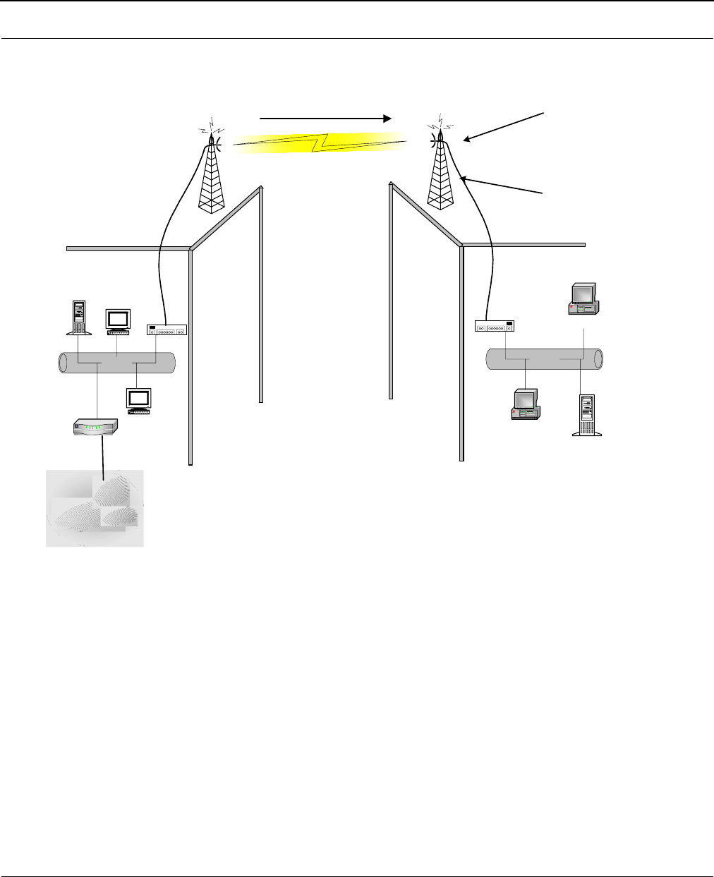
SPEEDLAN 8500 Series Installation and Operation User Guide
7-12 Setting Up the IP Addresses (IP Host Setup)
Diagram of Incoming NAT
Incoming NAT allows you to specify ports on the private network that you would like to be available
on the public network. For example, if a web server is being hosted on a public network in Building
B (IP Address 10.0.0.3), you can create a pair that will specify that all requests on the public IP
address, Port 80, be forwarded to IP Address 10.0.0.3 on the private IP address, Port 80.
Inbound Port 80 request is re-addressed
to Private address 10.0.0.3. Then, it is
forwarded across the private network
Internet
Ethernet
Router
204.101.20.1
SPEEDLAN A
Hub
SPEEDLAN B
Private Address on Local Interface
10.0.0.1
10.0.0.2
10.0.0.4
Ethernet
Hub
Web Server
10.0.0.3
Public Address on Remote Interface
204.101.20.3
Building A Building B

SPEEDLAN 8500 Series Installation and Operation User Guide
Setting Up the IP Addresses (IP Host Setup) 7-13
Part II - Setting Up the IP Address
The following section discusses DHCP client (and interface), DHCP Server, Static IP addresses, and
Outgoing and Incoming NAT.
Note: Before you begin, confirm that you have properly read the configuration from the
SPEEDLAN IDU you want to configure. Then, perform the following tasks: Open the
SPEEDLAN Configurator. From the File menu, choose Open Remote Config.... Then,
click Scan. The Scan dialog box appears. Select the appropriate IDU and click OK.
Click OK again. A message box appears confirming that the "Configuration has been
read from the IDU" (i.e., 128.104.224.1). Click OK.
To set up the IP address, do ONE of the following:
•Enable DHCP client for dynamic addressing. For more information, see Enabling the DHCP
Client and Choosing the Appropriate Interface, page 7-14, OR
• Assign a static IP address. For more information, see Assigning a Static IP Address,
page 7-18.
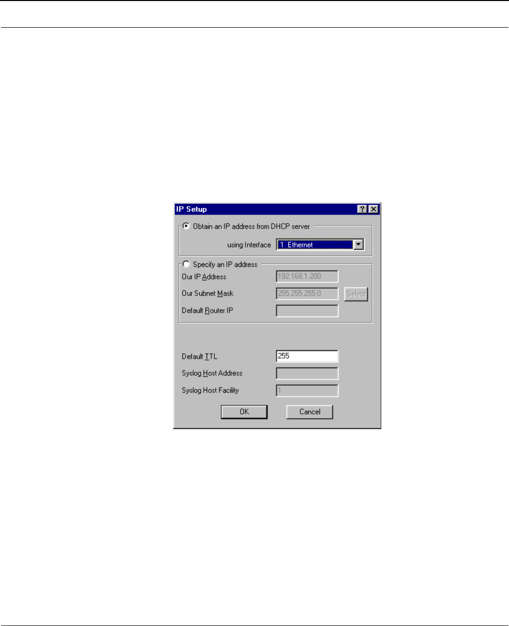
SPEEDLAN 8500 Series Installation and Operation User Guide
7-14 Setting Up the IP Addresses (IP Host Setup)
Enabling the DHCP Client and Choosing the Appropriate Interface
Note: Before you begin, confirm that you have properly read the configuration from the
SPEEDLAN IDU you want to configure. Then, perform the following tasks: Open the
SPEEDLAN Configurator. From the File menu, choose Open Remote Config.... Then,
click Scan. The Scan dialog box appears. Select the appropriate IDU and click OK.
Click OK again. A message box appears confirming that the "Configuration has been
read from the IDU" (i.e., 128.104.224.1). Click OK.
To enable the DHCP client and choose the appropriate interface, do the following:
1From the Setup menu, choose IP Setup. The IP Setup dialog box appears.
2Select the Obtain an IP address from DHCP Server option.
3Next, select the interface for Ethernet or wireless network from the Using Interface drop-
down list. Make sure that you select the interface where the DHCP server is located.
Note: The information for Default TTL should already be entered. The IP host on the Internet
sends out each packet with a default "Time to Live" parameter. If you want to override
the factory default of 64 attempts, you can specify your new default here. This
parameter should not be changed less you are very familiar with IP
functionality and how the Time to Live parameter will affect how packets are
treated by your network, as well as the network to which you are bridged (or
routed).
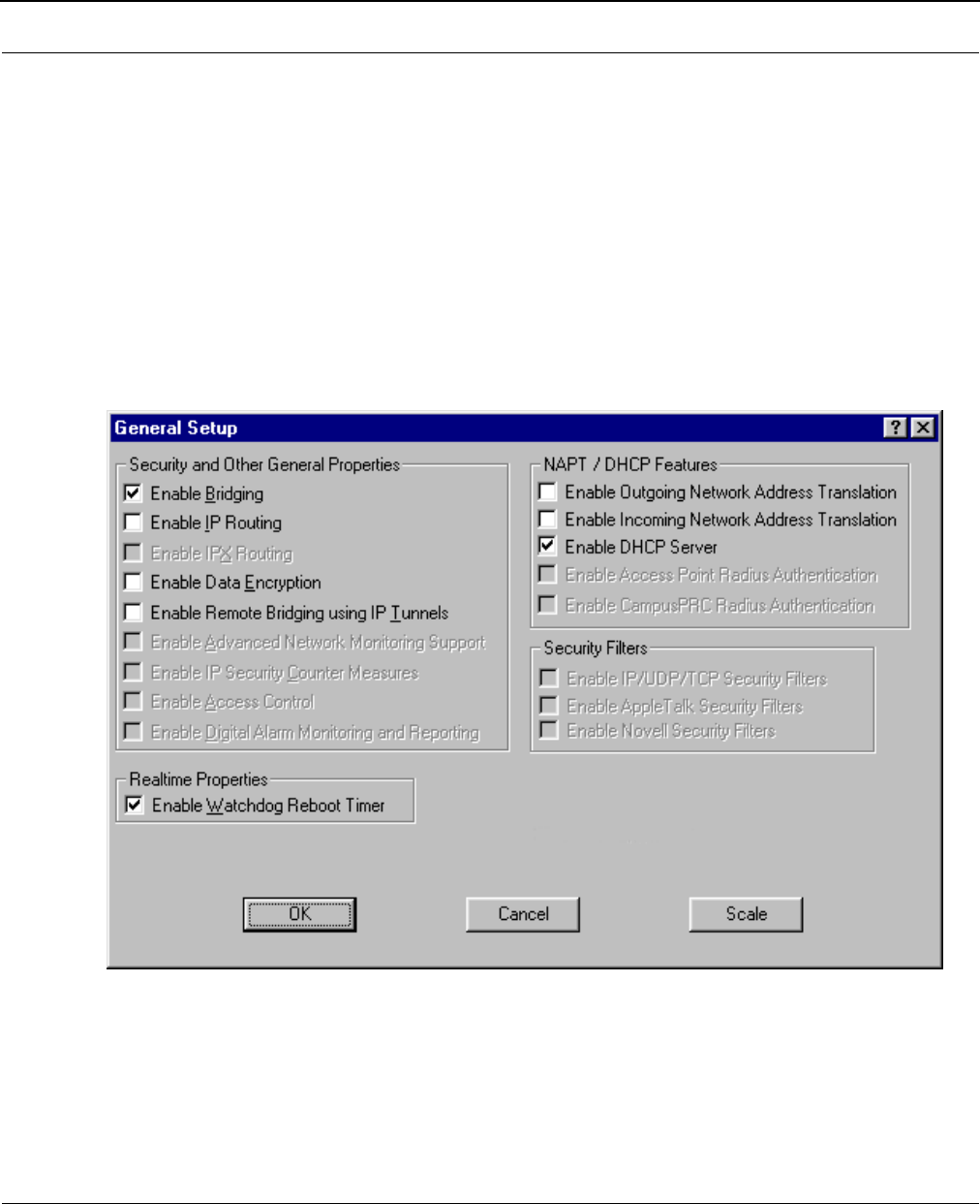
SPEEDLAN 8500 Series Installation and Operation User Guide
Setting Up the IP Addresses (IP Host Setup) 7-15
Enabling the DHCP Server on the SPEEDLAN
Note: Before you begin, confirm that you have properly read the configuration from the
SPEEDLAN IDU you want to configure. Then, perform the following tasks: Open the
SPEEDLAN Configurator. From the File menu, choose Open Remote Config.... Then,
click Scan. The Scan dialog box appears. Select the appropriate IDU and click OK.
Click OK again. A message box appears confirming that the "Configuration has been
read from the IDU" (i.e., 128.104.224.1). Click OK.
To enable the DHCP Server on the SPEEDLAN, do the following:
1From the Setup
SetupSetup
Setup menu, choose General Setup
General SetupGeneral Setup
General Setup. The General Setup dialog box appears.
2Select the Enable DHCP Server check box; this will enable you to set up the DHCP Server.
Note: You do not need to enable NAT (Outgoing and Incoming) in order to use SPEEDLAN’s
DHCP Server. Please read the sections of this manual describing those options carefully
before enabling either NAT feature.
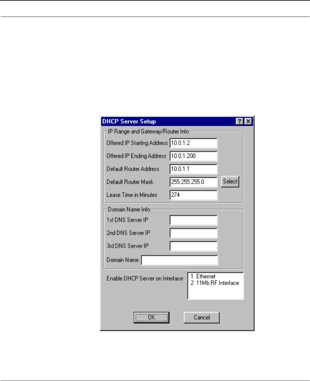
SPEEDLAN 8500 Series Installation and Operation User Guide
7-16 Setting Up the IP Addresses (IP Host Setup)
•Enable Outgoing Network Address Translation
This feature enables a company to map the private networks IP addresses into one or
more global public network IP addresses. This means that outsiders will only view the
single (or more if designated) IP network address assigned for global viewing on the
Internet. For more information, see Outgoing NAT, page 7-20.
•Enable Incoming Network Address Translation
This feature enables a company to unmap public network IP address into private net-
work IP addresses. For more information, see Incoming NAT, page 7-22.
3From the Setup menu, choose DHCP Server Setup. The DHCP Server Setup dialog box
appears.
4Enter the IP range and gateway/router information:
•Offered IP Starting Address
This is the start of the block of allowed IP addresses.

SPEEDLAN 8500 Series Installation and Operation User Guide
Setting Up the IP Addresses (IP Host Setup) 7-17
•Offered IP Ending Address
This is the end of the block of allowed IP addresses.
•Default Router Address
This is the router that initially accepts or transfers packets to the directly connected
networks or static networks.
•Default Router Mask
This is the subnet mask of the default router.
•Lease Time in Minutes
This is the amount of minutes that the computer can use the assigned IP address. When
the time is up, the IP address will revert to the pool of available addresses and can be
reassigned to another computer. The maximum time is 300 minutes.
Note: Click Select to view the IP Mask List. Select the appropriate IP Mask and click OK.
5Enter the domain name information:
•1st DNS Server IP
This setting will specify the client’s first DNS Server.
•2nd DNS Server IP
This setting will specify the client’s secondary DNS server.
•3rd DNS Server IP
If needed, this setting will specify the client’s third DNS server.
•Domain Name
This is the web domain name of the organization on the Internet such as “www.speed-
lan.com”. It is not necessary to use the first portion of the domain name leaving the
entry as “Speedlan.com”.
6Select the interface on which you want to Enable DHCP (i.e., Ethernet or wireless interface).
Note: If the requests for an IP address will be received through the wired Ethernet interface,
select #1 Ethernet. If the requests will be received through RF interface from a
remote PC, select #2 11 Mb RF Interface.
7Click OK.
8After you have finished entering the appropriate information, click OK.
9Now save the changes to the IDU. From the File menu, choose Save Config.
10 A message box appears informing you that the information will be saved to the IDU or
router. Click Yes .
11 The Configurator confirms that the configuration has been saved. Click OK. The SPEED-
LAN 8100 & 8200 IDUs will automatically reboot at this point.
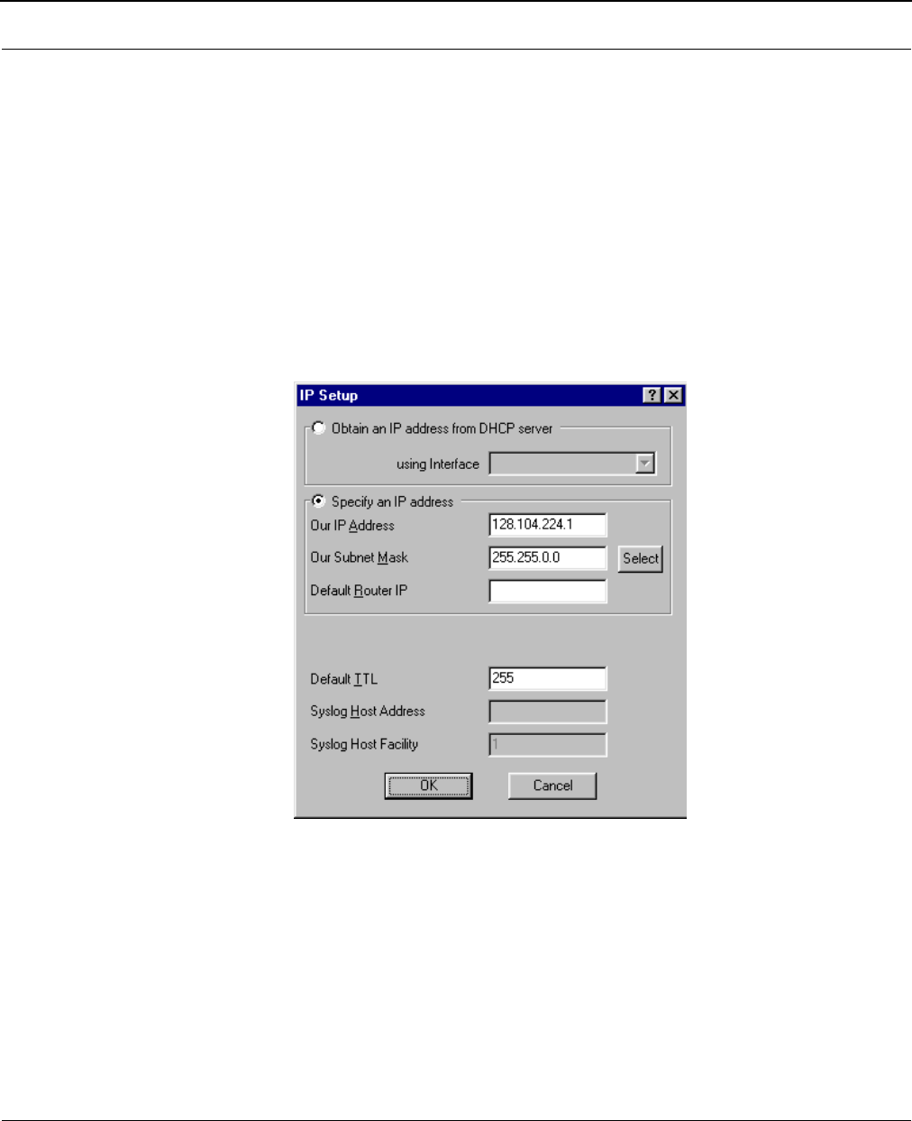
SPEEDLAN 8500 Series Installation and Operation User Guide
7-18 Setting Up the IP Addresses (IP Host Setup)
Assigning a Static IP Address
Note: Before you begin, confirm that you have properly read the configuration from the
SPEEDLAN IDU you want to configure. Then, perform the following tasks: Open the
SPEEDLAN Configurator. From the File menu, choose Open Remote Config.... Then,
click Scan. The Scan dialog box appears. Select the appropriate IDU and click OK.
Click OK again. A message box appears confirming that the "Configuration has been
read from the IDU" (i.e., 128.104.224.1). Click OK.
To physically assign a static IP address, do the following:
1From the Setup menu, choose IP Setup. The IP Setup dialog box appears.
2Select the Specify an IP address option. Enter the following information:
•Our IP Address
The unique number assigned by the network administrator, ISP or host provider. This
tells network the location (IP address) of this device on the Internet
(i.e., 128.104.224.1).
•Our Subnet Mask
This term allows network administrators to mask section(s) (depending on the class
specified) of the octets in the network address. Each octet used in the subnet mask is
assigned to a data link. The leftover octet(s) are assigned to the remaining nodes.

SPEEDLAN 8500 Series Installation and Operation User Guide
Setting Up the IP Addresses (IP Host Setup) 7-19
Note: For more information, see Subnetting a Network, page 7-5. Once the packet has
traveled to the appropriate network, it goes through a masking process. A subnet mask
is composed of zeros (0s) and ones (1s). This tells the router which addresses to look
under and which ones not to look under. Therefore, subnet masking allows the router
to transfer the packet traffic more quickly than a network without a subnet. Again, this
address is obtained from the network administrator, IP host, or host provider.
•Default Router IP
If you have an established network, use the IP address for the router already set up for
that network. If you do not have an established network, leave this entry blank.
•Default TTL
This information should already be entered. The IP host on the Internet will send out
each packet with a default "Time to Live" parameter. If you want to override the factory
default of 64 attempts, you can specify your new default here. This parameter should
not be changed unless you are very familiar with IP functionality and how the Time to
Live parameter will affect how packets are treated by your network, as well as the
network to which you are IDUd (or routed).
Note: Click Select to view the IP Mask List. Select the appropriate IP Mask and click OK.
3After you have finished entering the appropriate information, click OK.
4Now save the changes to the IDU. From the File menu, choose Save Config.
5A message box appears informing you that the information will be saved to the IDU (i.e.,
128.104.22.4). Click Yes.
6The Configurator confirms that the configuration has been saved. Click OK. The computer
will reboot at this point.
Note: If you want to set up NAT, see Part III - Setting Up NAT, page 7-20.
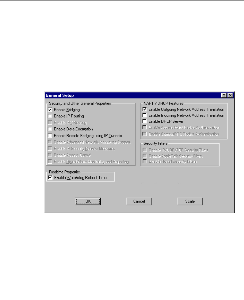
SPEEDLAN 8500 Series Installation and Operation User Guide
7-20 Setting Up the IP Addresses (IP Host Setup)
Part III - Setting Up NAT
This section explains how to setup outgoing and incoming Network Address Translation (NAT). For
more information on outgoing and incoming NAT, see Diagram of Outgoing NAT, page 7-11 and
Diagram of Incoming NAT, page 7-12.
Outgoing NAT
To setup outgoing NAT, do the following:
1 From the Setup
menu, choose General Setup. The General Setup dialog box appears.
2Select the Enable Outgoing Network Address Translation check box. Click OK.
3From the Setup menu, choose Outgoing Network Address Translation Setup.
4The Outgoing Address Translation Setup dialog box appears.
Note: NAT is a useful tool that will be enabled the majority of the time on the remote side of
the wireless connection. It is rarely enabled on the base station. NAT is also useful to
have private networks connected to public networks (i.e., the Internet) without needing
a public IP address for every node. By using only one public IP address, NAT controls
who in the private network made a request to an address in the public network.
This translates the IP addresses from one side to another, hiding the private network
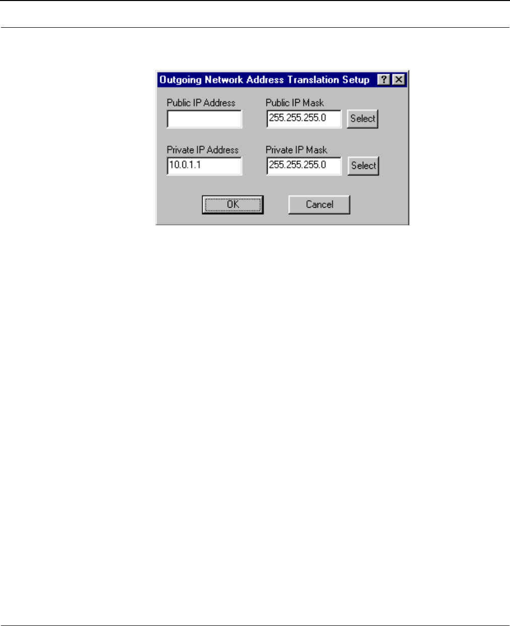
SPEEDLAN 8500 Series Installation and Operation User Guide
Setting Up the IP Addresses (IP Host Setup) 7-21
from the public. This means that the public will view only one public and valid IP
address.
5Enter the appropriate outgoing information:
•Public IP Address
This is the IP address for the outside network. If you have more than one public
address, you can assign it to a node on a private network (One-to-One NAT). There-
fore, all requests for a particular IP address from the outside or public network will be
translated to the appropriate private IP address. This may be necessary if you have a
server or workstation (host) that needs to be connected to a remote network.
•Private IP Address
This is the IP address for the inside or private network only, which hides behind the Pub-
lic IP address.
•Public IP Mask
This address assigns the Subnet mask to the Public (Ethernet) portion of the SPEEDLAN
IDU.
•Private IP Mask
This address assigns the Subnet mask to the private network interface.
Note: Click Select to view the IP Mask List. Select the appropriate IP Mask and click OK.
6Click OK.
7After you have finished entering the appropriate information, click OK.
8Now save the changes to the IDU or router. From the File menu, choose Save Config.
9A message box appears informing you that the information will be saved to the IDU or
router. Click Yes . The Configurator confirms that the configuration has been saved. Click
OK. The SPEEDLAN 8100 & 8200 IDUs will automatically reboot at this point.
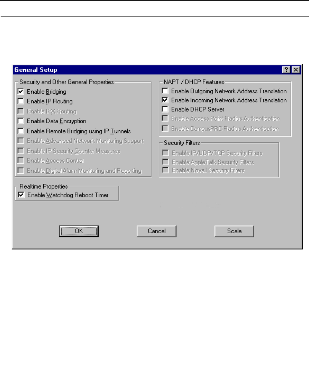
SPEEDLAN 8500 Series Installation and Operation User Guide
7-22 Setting Up the IP Addresses (IP Host Setup)
Incoming NAT
To set up incoming IP network address for NAT, do the following:
1From the Setup menu, choose General Setup. The General Setup dialog box appears.
2Select the Enable Incoming Network Address Translation check box. Click OK.
3From the Setup menu, choose Incoming Network Address Translation Setup.
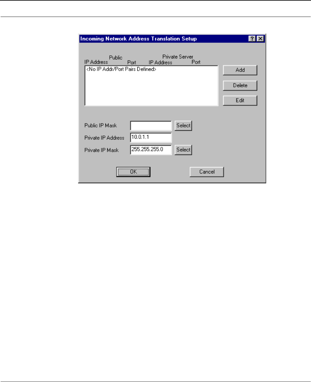
SPEEDLAN 8500 Series Installation and Operation User Guide
Setting Up the IP Addresses (IP Host Setup) 7-23
4The Incoming Address Translation Setup dialog box appears.
5Enter the appropriate incoming information:
•Public IP Address
This is the IP address for the outside network. If you have more than one public
address, you can assign it to a node on the private network (One-to-One NAT).
Therefore, all requests for a particular IP address from the outside or public network will
be translated to the appropriate private IP address. This may be necessary if you have
a server or workstation (or computer) that needs to be connected to a remote network.
•Private IP Address
This is the IP address for the inside network only, which hides behind the public IP
address.
•Private IP Mask
This address assigns the Subnet mask to the private network interface.
Note: Click Select to view the IP Mask List. Select the appropriate IP Mask and click OK.
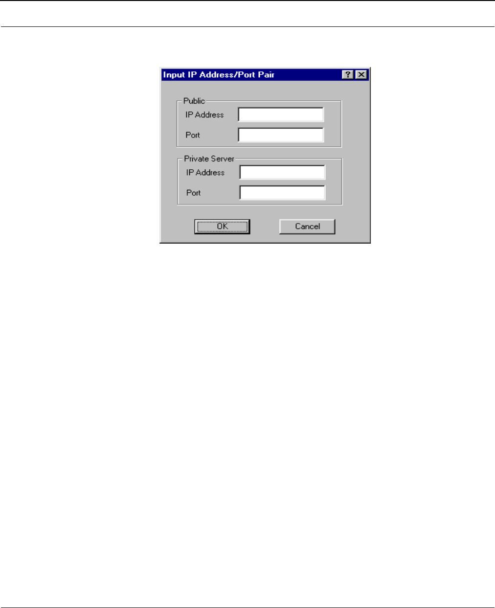
SPEEDLAN 8500 Series Installation and Operation User Guide
7-24 Setting Up the IP Addresses (IP Host Setup)
6Click Add to enter another IP address/port pair. The Input IP Address/Port Pair dialog
box appears.
7Then enter the following information as appropriate. Then, click OK to close this dialog
box.
•Public IP Address
This is the IP address for the outside network. All requests for a particular IP address
from the outside or public network will be translated to the appropriate private IP
address.
•Public Port
This item will allow you to assign a particular port that you would like to have one of
the private IP addresses to be able to respond to. Here are a few of the more common
ports used:
FTP - 20 & 21
SMTP – 25
DNS – 53
HTTP – 80
NNTP - 119
•Private Server IP Address
This is the IP address of the server or workstation (or computer) where you want to get
the “received message” for this port assignment.
•Private Server Port
This is the port where you want to have the server receive the messages.
8Click Delete to permanently remove the IP address/port pair selected. Click Edit
to modify
the IP address/port pair selected. Click OK. You will return to the Incoming Network
Address Translation Setup dialog box.

SPEEDLAN 8500 Series Installation and Operation User Guide
Setting Up the IP Addresses (IP Host Setup) 7-25
9After you have finished entering the appropriate information, click OK.
10 Now save the changes to the IDU or router. From the File menu, choose Save Config.
11 A message box appears informing you that the information will be saved to the IDU or
router. Click Yes .
12 The Configurator confirms that the configuration has been saved. Click OK. The SPEED-
LAN 8100 & 8200 IDUs will automatically reboot at this point.

SPEEDLAN 8500 Series Installation and Operation User Guide
7-26 Setting Up the IP Addresses (IP Host Setup)
Notes:___________________________________________________
________________________________________________________
________________________________________________________
________________________________________________________
________________________________________________________
________________________________________________________
________________________________________________________
________________________________________________________
________________________________________________________
________________________________________________________
________________________________________________________
________________________________________________________
________________________________________________________
________________________________________________________
________________________________________________________
________________________________________________________
________________________________________________________
________________________________________________________
________________________________________________________
________________________________________________________
________________________________________________________
________________________________________________________
________________________________________________________
________________________________________________________
________________________________________________________
________________________________________________________
________________________________________________________
________________________________________________________
________________________________________________________
________________________________________________________

Chapter 8
IP-Router Setup
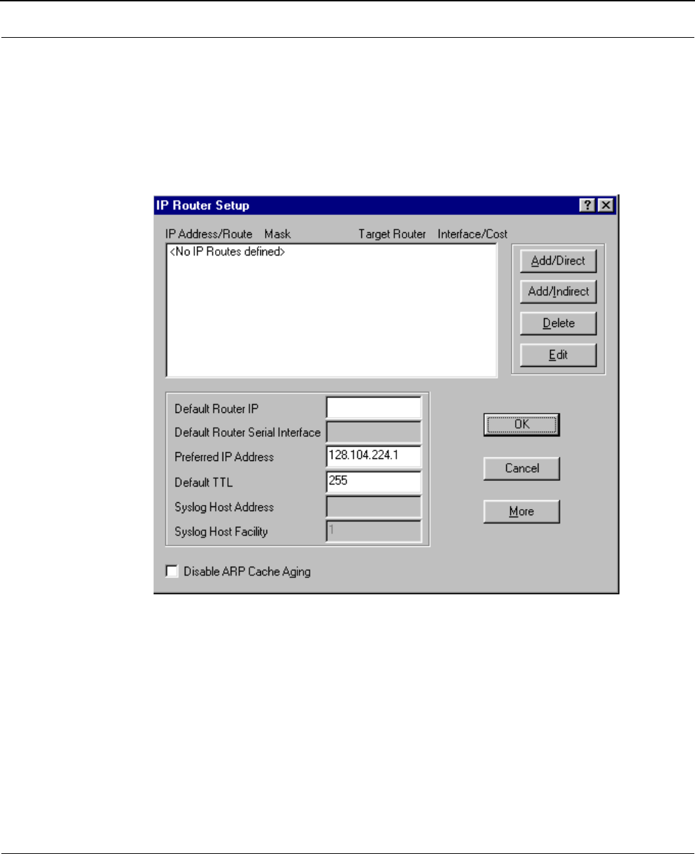
SPEEDLAN 8500 Series Installation and Operation User Guide
8-2 IP-Router Setup
IP Routing Setup
IP Routing in the General Setup dialog box must be enabled for this dialog box to appear. Then,
choose IP Routing Setup from the Setup menu on the SPEEDLAN Configurator. This dialog box
must be completed before saving any configuration in which IP Routing has been enabled. Saving
the configuration with incomplete entries in the route table will make the SPEEDLAN 8500
IDU inoperable. Enter the appropriate information as described below:
•Default Router (IP Address)
This entry should be set to the IP address of the default router that the SPEEDLAN 8500 IDU
is to use when it does not know where to route a particular IP packet.
•Default Router Interface
This entry should be set to the interface to which the default router is connected.
•Preferred IP Address
From time to time routers will transmit unsolicited IP packets such as SNMP Traps, Syslog,
RIP, or IP ARP packets. Most routers randomly use one of the IP addresses from one of the
router's interfaces as the source IP address for these packets. On the IDU you can specify
the source IP address that you prefer to use for these packets.
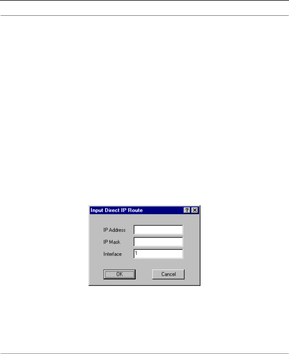
SPEEDLAN 8500 Series Installation and Operation User Guide
IP-Router Setup 8-3
•Default TTL
IP hosts on the Internet send out packets with a default "Time To Live" parameter. If you want
to override the factory default of 64 attempts, specify your new default value here.
• Disable ARP-Cache Aging
Use this option if you want to keep a permanent record of the IP to Ethernet addresses table
for each computer directly connected to an interface on the IDU. This feature is helpful
when used in conjunction with a corporate-wide SNMP monitoring tool to create a
database of all Ethernet-to-IP address combinations on your network. A standard IP router
and the IDU will age their ARP cache entries. It will time out and delete the ARP entries after
a certain specified period (usually 10 minutes). The IDU has the option of not aging
(deleting) any ARP cache entries. This will not normally cause any IP network problems, but
this could result in a large ARP cache table. Since the typical IDU can hold over 10,000
ARP entries, this is not normally a problem.
Add/Direct Button
Click this button to specify the direct routes for each of the interfaces on the IDU. Direct routes are
those that are directly connected to the interfaces. As an example, if Interface 1 is to have subnet
128.146.6.0 connected to it and an IP address of 128.146.6.1 with a subnet mask of
255.255.255.0, an entry in this dialog box should be set up as: IP Address = 128.146.6.1; IP
Mask = FFFFFF00; and Interface = 1.
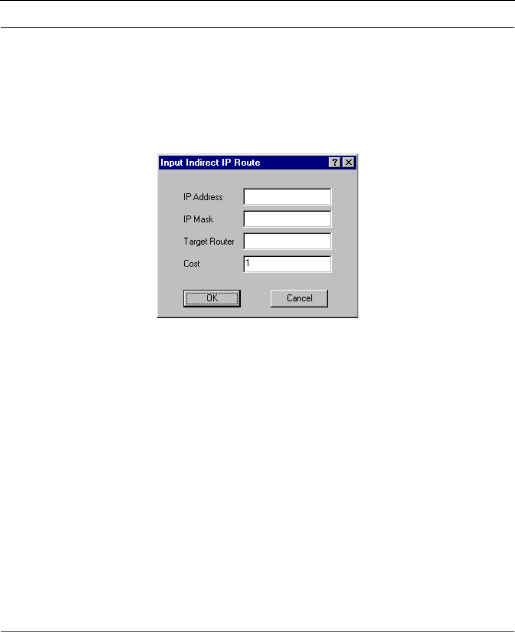
SPEEDLAN 8500 Series Installation and Operation User Guide
8-4 IP-Router Setup
Add/Indirect Button
Click this button to specify the indirect routes for this IDU. These routes are sometimes referred to as
static routes. You can use indirect routes to define the way to get to subnets that are attached to
other routers in your network. As an example, if subnet 198.17.74.0 is attached to router
128.146.11.20, in order for this IDU to route packets to 198.17.74.1 you should specify an entry
that is set up as: IP Address = 198.17.74.0; IP Mask = FFFFFF00; Next Hop = 128.146.11.20
with Cost = 1.
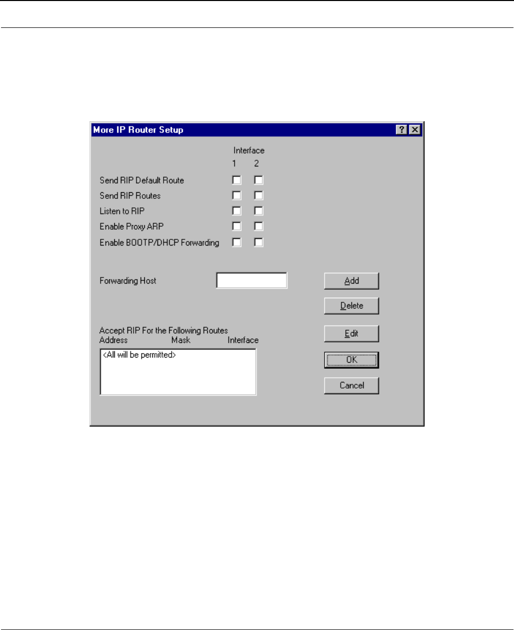
SPEEDLAN 8500 Series Installation and Operation User Guide
IP-Router Setup 8-5
More Button - RIP Routing
Click this button on the IP Router Setup dialog box to enable RIP. Wave Wireless IDUs support what
is known as RIP (Routing Information Protocol). RIP allows users to permit network equipment to
communicate with each other to handle the routing plan of your network. Select the appropriate
check boxes as described below:
• Send RIP Default Route
Enabling this feature instructs the IDU to inform the network (via RIP) that it is the default
router for that network. This feature should only be enabled if this IDU is the only
default router on the local network.
•Send RIP Routes
Enabling this feature instructs the IDU to forward all route information gathered and stored
by this IDU through the interface(s) selected. This is normally used in conjunction with Listen
to RIP which instructs the IDU to gather RIP information from other RIP devices on your net-
work.

SPEEDLAN 8500 Series Installation and Operation User Guide
8-6 IP-Router Setup
•Listen to RIP
This function enables the IDU to listen for and update its RIP information. The routes gath-
ered in this manner come from other RIP-enabled routers on your network. This feature is
normally used in conjunction with Send RIP Routes, which instructs the IDU to pass along all
RIP information it has gathered to other RIP devices on your network.
•Enable Proxy ARP
This feature allows the IDU to be used as the proxy host for users on the local network. This
instructs the IDU to act as a "proxy" for the local destination host. This is used in
circumstances that require connections not normally permitted for individual users on a
network.
•Enable BOOTP/DHCP Forwarding
This feature allows the IDU to pass BOOTP and DHCP requests across the wireless network.
•Forwarding Host
Defines the IP address of the device configured to act as the forwarding host for BOOTP
and DHCP messages in a routed network.
•Accept RIP For the Following Routes
Normally RIP instructs the IDU to forward all route information gathered to all RIP devices
located on you network. Specifying devices in the RIP Access List allows you to limit which
devices will be sent RIP. The devices specified in this list will be the only devices to receive
RIP, while all other devices will be denied the RIP information stored on this IDU.

Chapter 9
SNMP Setup
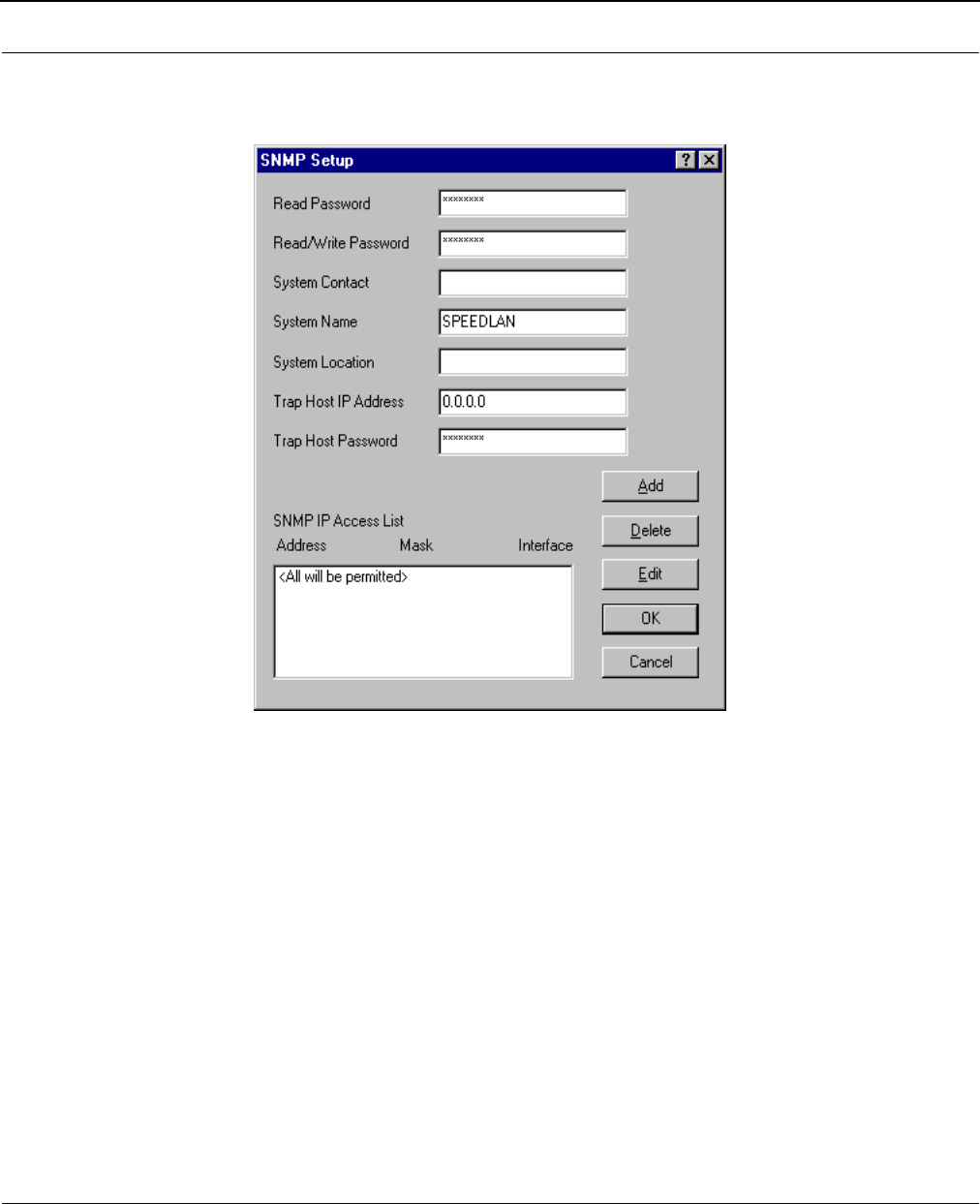
SPEEDLAN 8500 Series Installation and Operation User Guide
9-2 SNMP Setup
SNMP Setup
Choose SNMP Setup from the Setup menu of the SPEEDLAN Configurator to set up SNMP.
•Read Password
This is the read-only password used for SNMP support. It is the SNMP password needed to
read the Flash ROM Configuration and SNMP MIB variables. The factory-default value for
this variable is the string "public".
•Read/Write Password
This is the read/write password used for SNMP support. It is the SNMP password needed to
write the Flash ROM configuration and SNMP MIB variables into the IDU. The string should
be set to a value that is known only by you. The factory-default value for this variable is the
string "public" and should be changed to a string known only to you.
•System Contact
This field should contain the identification of the contact person for this SNMP-managed
node, together with information on how to contact this person.
•System Name
This field should contain the administratively assigned name for this managed node. By

SPEEDLAN 8500 Series Installation and Operation User Guide
SNMP Setup 9-3
convention, this is the node's fully qualified Internet Domain name (e.g.,
"IDU20.speedlan.com").
• System Location
This field should contain the physical location of this node. (e.g., "telephone closet, 3rd
floor").
•Trap Host IP Address
This is the IP address of a network-connected host that is set up to receive SNMP Trap mes-
sages from this IDU. If you do not have an SNMP Trap Host, set this to 0.0.0.0.
•Trap Host Password
This is the SNMP read/write password (community name) of the host that is set up to receive
SNMP Trap messages. This field is ignored if the Trap Host IP Address described above is
0.0.0.0.
•SNMP IP Access List
You can optionally set up a list of networks, subnets, and hosts that are authorized to access
the IDU via SNMP.
To modify the SNMP Access List, click Add, Delete, or Edit.
TIP

SPEEDLAN 8500 Series Installation and Operation User Guide
9-4 SNMP Setup
Note:____________________________________________________
________________________________________________________
________________________________________________________
________________________________________________________
________________________________________________________
________________________________________________________
________________________________________________________
________________________________________________________
________________________________________________________
________________________________________________________
________________________________________________________
________________________________________________________
________________________________________________________
________________________________________________________
________________________________________________________
________________________________________________________
________________________________________________________
________________________________________________________
________________________________________________________
________________________________________________________
________________________________________________________
________________________________________________________
________________________________________________________
________________________________________________________
________________________________________________________
________________________________________________________
________________________________________________________
________________________________________________________
________________________________________________________
________________________________________________________

Chapter 10
System Access Setup
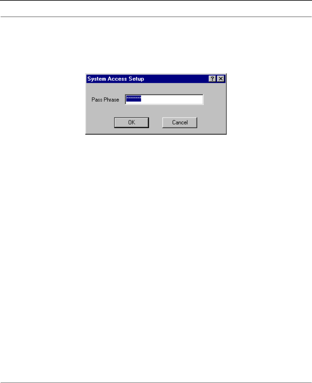
SPEEDLAN 8500 Series Installation and Operation User Guide
10-2 System Access Setup
System Access Setup
Choose System Access Setup from the Setup menu of the SPEEDLAN Configurator to enter a
password for the System Access Pass Phrase. This will enable you to create a connection between the
equipment or wireless IDUs. The default for the Pass Phrase is "public".
All wireless IDUs connected to the IDU are restricted to systems based on the System Access Pass
Phrase. Any wireless IDU that does not have the correct System Access Pass Phrase will not be to
establish a wireless data connection.

Chapter 11
SNMP Monitoring
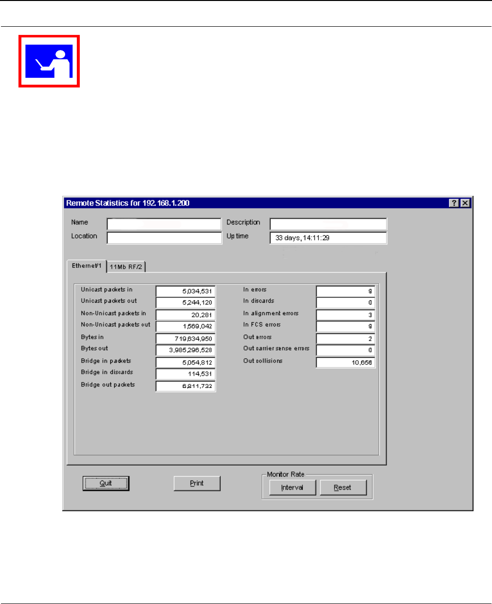
SPEEDLAN 8500 Series Installation and Operation User Guide
11-2 SNMP Monitoring
To monitor the SNMP results, choose the appropriate selection by choosing Monitor (on the
SPEEDLAN Configurator)+ Advanced + your selection.
Remote Statistics
In the Remote Statistics dialog box, you are presented with information regarding the way a IDU
handles packets as they are passing through an interface. Below you will find many useful items for
diagnosing and gathering traffic statistics for each interface.
TIP

SPEEDLAN 8500 Series Installation and Operation User Guide
SNMP Monitoring 11-3
•Unicast packets in
The number of subnetwork-unicast packets delivered to a higher-layer protocol.
•Unicast packets out
The total number of octets (bytes) transmitted out of the interface, including framing
characters.
•Non-Unicast packets in
The number of non-unicast (i.e., subnetwork-broadcast or subnetwork-multicast) packets
delivered to a higher-layer protocol.
•Non-Unicast packets out
The total number of octets (bytes) transmitted out of the interface, including framing
characters.
•Bytes in
Total number of octets (bytes) received on the interface, including framing characters.
•Bytes out
The total number of packets that have higher-layer protocols requested be transmitted to a
non-unicast (i.e., a subnetwork-broadcast or subnetwork-multicast) address, including those
that were discarded or not sent.
•IDU in discards
The count of valid frames that have been received which were discarded (i.e., filtered) by
the forwarding process.
•IDU out packets
The number of frames that have been transmitted by this port to its segment. Note that a
frame transmitted on the interface corresponding to this port is not counted by this object
unless it is for a protocol being processed by the local bridging function.
•In errors
The number of inbound packets that contained errors preventing them from being
deliverable to a higher-layer protocol.
•In discards
The number of inbound packets which were chosen to be discarded even though they were
deliverable. One possible reason for discarding such a packet could be to free up buffer
space.
•In Alignment Errors
A count of frames received on a particular interface that are not an integral number of
octets in length and do not pass the FCS check.
•In FCS Errors
A count of frames received on a particular interface that are an integral number of octets in
length, but do not pass the FCS check.

SPEEDLAN 8500 Series Installation and Operation User Guide
11-4 SNMP Monitoring
•Out Errors
The number of outbound packets that could not be transmitted because of errors.
•Out Carrier Sense Errors
The number of times that the carrier-sense condition was lost or never asserted when the
SPEEDLAN 8500 IDU attempted to transmit a frame on a particular interface.
•Out Collisions
A count of successfully transmitted frames on a particular interface for which transmission is
inhibited by exactly one or more collisions, plus the number of times that a collision is
detected on a particular interface later than 512 bit-times into the transmission of a packet.
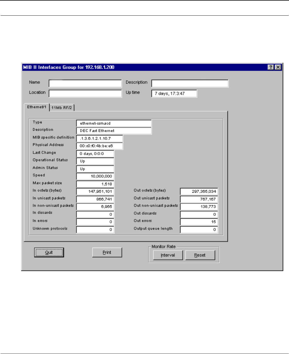
SPEEDLAN 8500 Series Installation and Operation User Guide
SNMP Monitoring 11-5
Interface Monitor
The interfaces table contains information on the IDU's interface(s). Each interface is thought of as
being attached to a `subnetwork'. Note that this term should not be confused with `subnet' which
refers to an address-partitioning scheme used in the Internet suite of protocols.
•Type
The type of interface, distinguished according to the physical-link protocols immediately
below the network layer in the protocol stack. The possible types are: other, regular1822,
hdh1822, ddn-x25, rfc877-x25, ethernet-csmacd, iso88023-csmacd, iso80024-tokenbus,
iso88025-tokenring, iso99026-man, starLan, proteon-10Mbit, proteon-80Mbit,
hyperchannel, fddi, lapb, sdlc, ds1, e1, basicISDN, PrimaryISDN, propPointToPointSerial,
ppp, softwareloopback, eon, ethernet-3Mbit, nsip, slip, ultra, ds3, sip, frame-relay.

SPEEDLAN 8500 Series Installation and Operation User Guide
11-6 SNMP Monitoring
•Description
A textual string containing information about the interface. This string should include the
name of the manufacturer, the product name, and the version of the hardware interface.
•MIB specific definator
A reference to MIB definitions specific to the particular media being used to realize the
interface. For example, if the interface is being realized by an Ethernet, then the value of this
object refers to a document defining objects specific to the Ethernet. If this information is not
present, its value will be set to 0.
•Physical Address
The interface's address at the protocol layer immediately below the network layer in the
protocol stack. For interfaces which do not have such an address (e.g., a serial line), this
object should contain an octet string of zero length.
•Last Change
The value of sysUpTime at the time the interface entered its current operational state. If the
current state was entered prior to the last reinitialization of the local network-management
subsystem, then this object contains a value of zero.
•Operational Status
The state of the interface. The testing state indicates that no operational packets can be
passed. Up - ready to pass packets; Down - cannot pass packets; testing - in some test
mode.
•Admin Status
The desired state of the interface. The testing state indicates that no operational packets can
be passed.
•Speed
An estimate of the interface's current bandwidth in bits per second. For interfaces which do
not vary in bandwidth or whose bandwidth can't be accurately estimated, this object should
contain the nominal bandwidth.
•Max packet size
The size of the largest datagram which can be sent/received on the interface, specified in
octets. For interfaces used for transmitting network datagrams, this is the size of the largest
network datagram that can be sent on the interface.
•In octets (bytes)
The total number of octets (bytes) received on the interface, including framing characters.
•In unicast packets
The number of subnetwork-unicast packets delivered to a higher-layer protocol.
•In non-unicast packets
The number of non-unicast (i.e., subnetwork-broadcast or subnetwork-multicast) packets
delivered to a higher-layer protocol.

SPEEDLAN 8500 Series Installation and Operation User Guide
SNMP Monitoring 11-7
•In discards
The number of inbound packets to which were chosen to be discarded even they were
deliverable to a higher-layer protocol. One possible reason for discarding such a packet
could be to free up buffer space.
•Out discards
The number of outbound packets to which were chosen to be discarded even they were
deliverable to a higher-layer protocol. One possible reason for discarding such a packet
could be to free up buffer space.
•In errors
The number of inbound packets that contained errors preventing them from being
deliverable to a higher-layer protocol.
•Unknown protocols
The number of packets received via the interface which were discarded because of an
unknown or unsupported protocol.
•Out octets (bytes)
The total number of octets (bytes) transmitted out of the interface, including framing
characters.
•Out unicast packets
The total number of packets that higher-layer protocols requested be transmitted to a sub-
network-unicast address, including those that were discarded or not sent.
•Out non-unicast packets
The total number of packets that higher-layer protocols requested be transmitted to a non-
unicast (i.e. a subnetwork-broadcast or subnetwork-multicast) address, including those that
were discarded or not sent.
•Out errors
The number of outbound packets that contained errors preventing them from being
transmitted via this interface.
•Output queue length
The total number of octets (bytes) waiting to be transmitted via this interface.
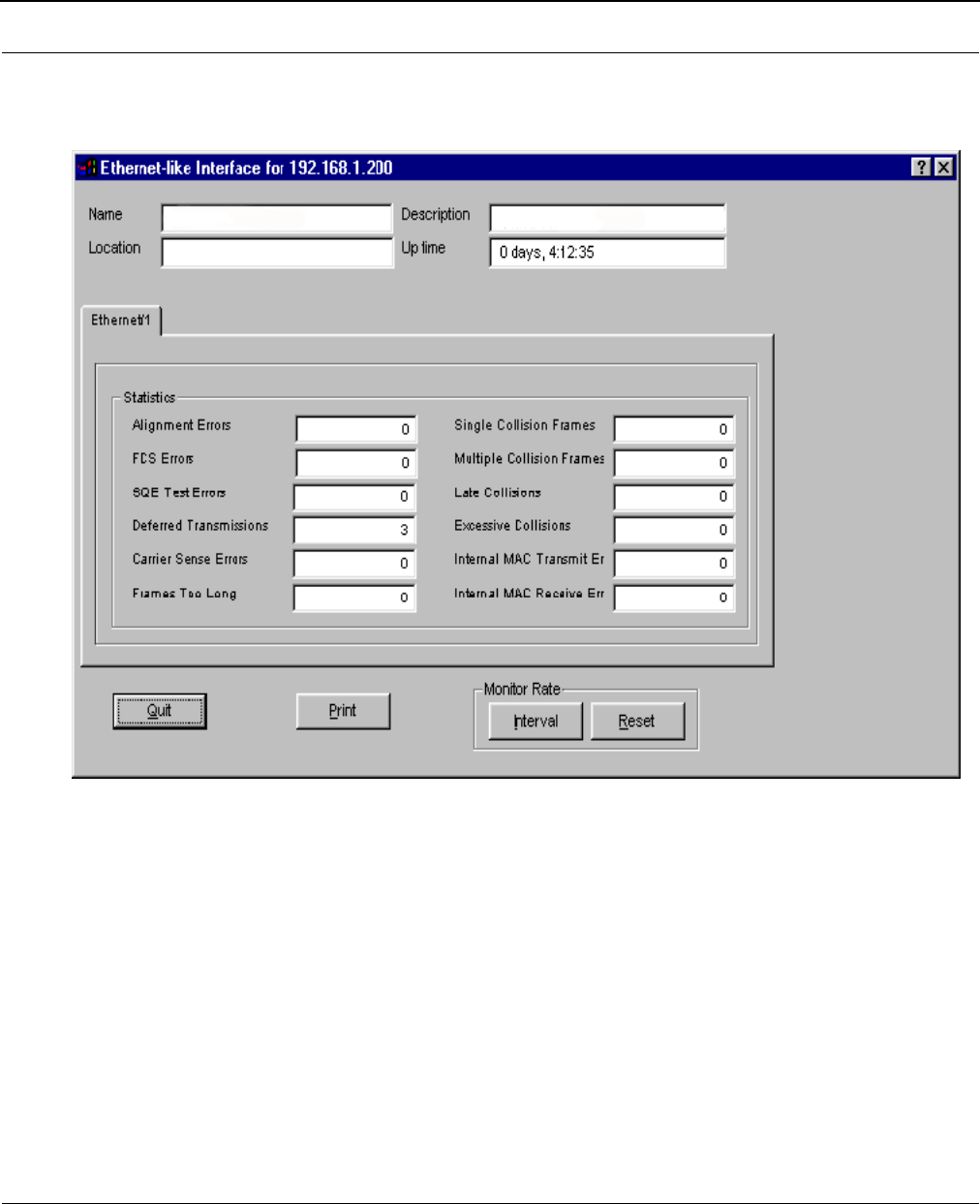
SPEEDLAN 8500 Series Installation and Operation User Guide
11-8 SNMP Monitoring
Ethernet-like Interface Monitor
This displays information on the interfaces available for the device selected for Ethernet monitoring.
•Alignment Errors
These alignment errors appear when the station discards the transmission alignment. Errors
received on the Ethernet interface that are not an intergral number of octets in length and
do not pass the FCS check. This also applies to FCS Errors below.
•FCS Errors
These are data link protocols used with the frame check sequence, which allows the
receiver to detect collisions.
•SQE Test Errors
These test errors appear in the System Quality Evaluation process of the interface.
•Deferred Transmissions
These are the number of packets that were tossed.

SPEEDLAN 8500 Series Installation and Operation User Guide
SNMP Monitoring 11-9
•Carrier Sense Errors
These are errors appearing when two devices are trying to transmit at once. Therefore, a
collision occurs and is detected by all sense devices, and the transmission is delayed.
•Frames Too Long
This error appears when the data link header is too long.
•Single Collision Frames
Packets that had a single collision during transmission requiring a single re-transmission.
•Multiple Collision Frames
Packets that had a multiple collision during transmission requiring a multiple re-
transmission.
•Late Collisions
A packet that was not delivered to the transceiver on time.
•Internal MAC Transmit Errors
An internal error within the Medium Access Protocol during the transmission process.
•Internal MAC Receive Errors
An internal error within the Medium Access Protocol during the receiving process.
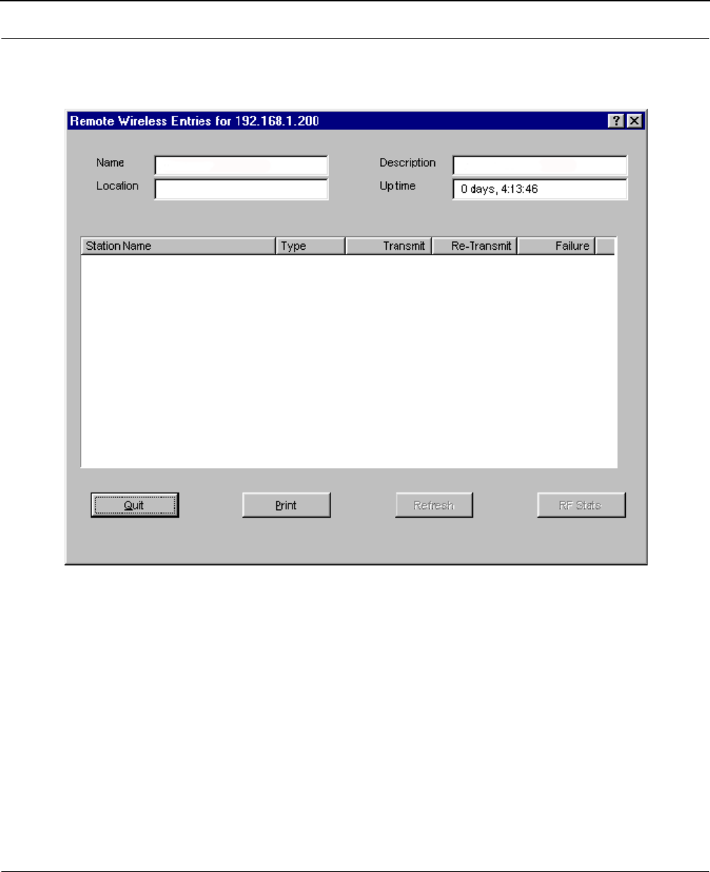
SPEEDLAN 8500 Series Installation and Operation User Guide
11-10 SNMP Monitoring
SectorPRC Station Entries
This displays the wireless stations connected to the IDU.
•Station Name
Name of system assigned in the SNMP Setup for a IDU or in the Network Control Panel for
Single Device Adapters (Note: Single Device Adapters will only communicate with a SPEED-
LAN 8000 series base station. They will appear on the Wireless Remote Entries
dialog box of a 4000 series base station, if the base can hear their RF signal.)
•Type
Valid entries are: Base, Remote, Peer, and Offline.
•Transmit
Number of transmissions from the wireless station.
•Re-Transmit
Number of re-transmissions from the wireless station.
Note: A high number of re-transmit errors usually indicates that the signal quality is poor.
G-Link Base 207,568 601 0
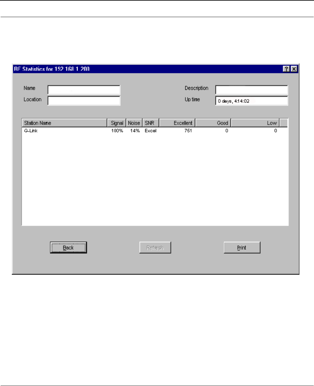
SPEEDLAN 8500 Series Installation and Operation User Guide
SNMP Monitoring 11-11
•Failure
Number of transmission failures from the wireless station.
Note: Click RF Stats to view the radio frequency statistics for the wireless station connected to
the IDU (as shown below). Then, click Back to return to this dialog box.
•Station Name
Name of the IDU.
•Signal
The higher the Signal Level, the better. This ratio should be between 50 to 70%. In order for
the link to be successful, you should have approximately 20 points higher than the noise.
•Noise
The higher the Signal Level, the better. This ratio should be between 50 to 70%. In order for
the link to be successful, you should have approximately 20 points higher than the noise.
•SNR (Signal-to-Noise Ratio)
Number of the signal divided by the number of noise. The higher the SNR is, the better.
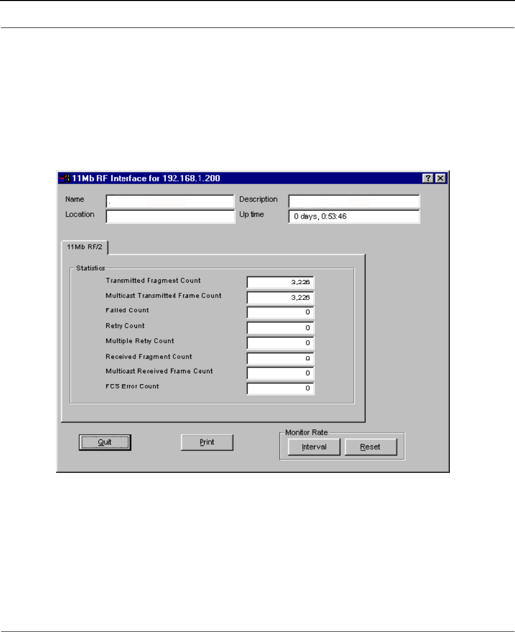
SPEEDLAN 8500 Series Installation and Operation User Guide
11-12 SNMP Monitoring
•Excellent, Good, Low
This displays the packet transmission rate. The packet count should be 98% or better.
Note: Click Back to return to the SectorPRC information.
11Mb RF Interface
This displays the interface(s) connected to the IDU.
•Transmitted Fragment Count
The number of frames transmitted.
•Multicast Transmitted Frame Count
The number of multicast frames transmitted.
•Failed Count
The number of frames that did not transmit.
•Multiple Retry Count
The number of multiple attempts to resend a frame.

SPEEDLAN 8500 Series Installation and Operation User Guide
SNMP Monitoring 11-13
•Received Fragment Count
The number of frames received.
•Multicast Received Frame Count
The number of multicast frames received.
•FCS Error Count
The number of data link protocols used with the frame check sequence, which allows the
receiver to detect collisions.
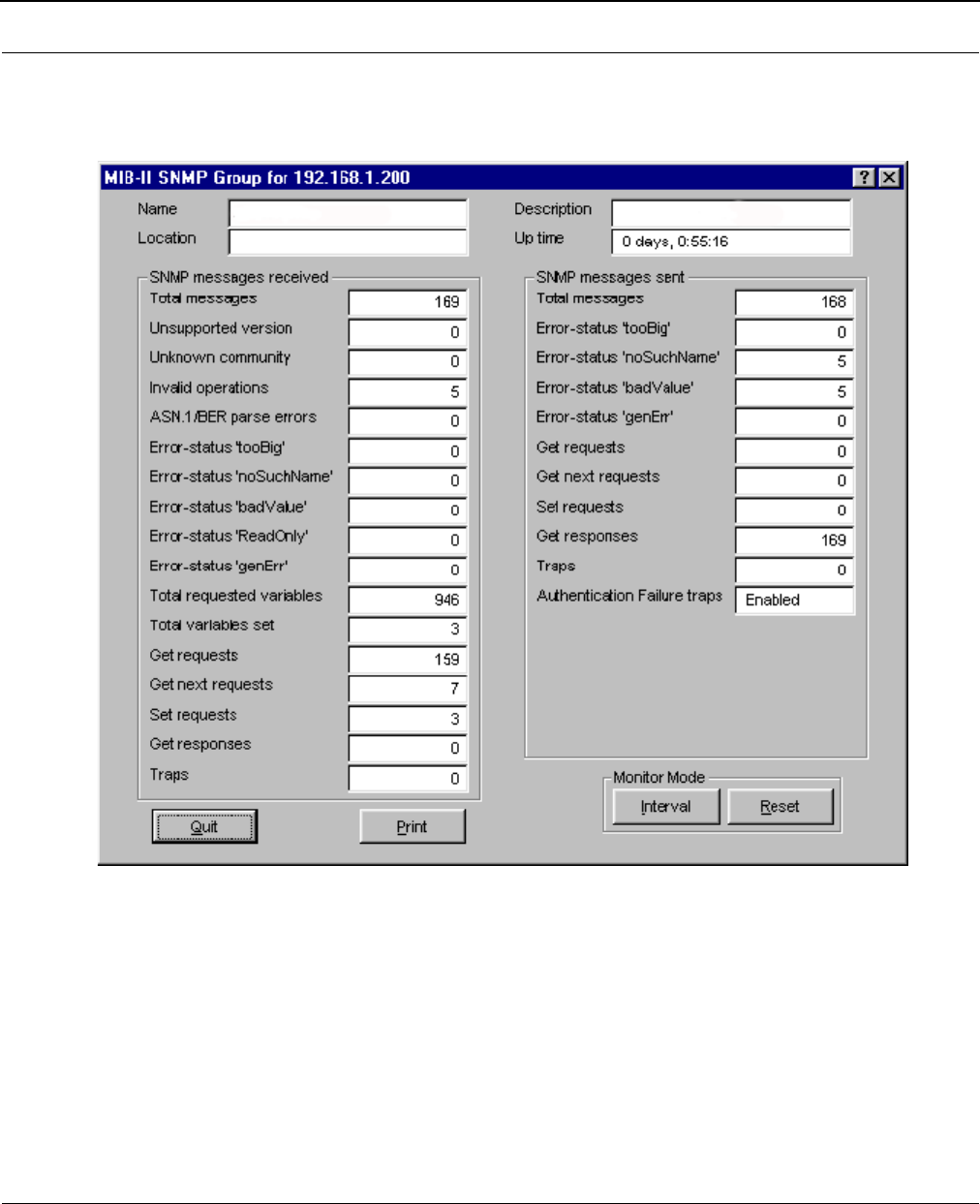
SPEEDLAN 8500 Series Installation and Operation User Guide
11-14 SNMP Monitoring
SNMP Monitor
This displays the SNMP messages that are received or sent.
SNMP Messages Received
•Total Messages
The total number of SNMP messages received.
•Unsupported Version
The total number of SNMP messages which were delivered to the SNMP protocol entity and
were for an unsupported SNMP version.

SPEEDLAN 8500 Series Installation and Operation User Guide
SNMP Monitoring 11-15
•Unknown Community
The total number of SNMP messages delivered to the SNMP protocol entity which used an
SNMP community name not known to the IDU.
•Invalid Operations
The total number of SNMP messages delivered to the SNMP protocol entity which
represented SNMP operations not allowed by the SNMP community named in the message.
•ASN.1/BER parse errors
The total number of ASN.1 or BER errors encountered by the SNMP protocol entity when
decoding received SNMP messages.
•Error-status `too big'
The total number of SNMP PDUs delivered to the SNMP protocol entity for which the value
of the error-status field was `too big'.
•Error-status `noSuchName'
The total number of SNMP PDUs delivered to the SNMP protocol entity for which the value
of the error-status field was `noSuchName'.
•Error-status `badValue'
The total number of SNMP PDUs delivered to the SNMP protocol entity for which the error-
status field was indicated `badValue'.
•Error-status `ReadOnly'
The total number of valid SNMP PDUs delivered to the SNMP protocol entity for which the
value of the error-status field was `ReadOnly'. It should be noted that it is a protocol error
to generate an SNMP PDU which contains the value `ReadOnly' in the error-status field;
use this field to detect incorrect implementations of SNMP.
•Error-status `genErr'
The total number of SNMP PDUs delivered to the SNMP protocol entity for which the error-
status field was `genErr'.
•Total requested variables
The total number of MIB objects retrieved successfully by the SNMP protocol entity as the
result of receiving valid SNMP Get-Request and Get-Next PDUs.
•Total variables set
The total number of MIB objects altered successfully by the SNMP protocol entity as the
result of receiving valid Set-Request PDUs.
•Get requests
The total number of SNMP Get-request PDUs accepted and processed by the SNMP proto-
col entity.

SPEEDLAN 8500 Series Installation and Operation User Guide
11-16 SNMP Monitoring
•Get next requests
The total number of SNMP Get-next PDUs accepted and processed by the SNMP protocol
entity.
•Set requests
The total number of SNMP Set-request PDUs accepted and processed by the SNMP proto-
col entity.
•Get responses
The total number of SNMP Get-response PDUs accepted and processed by the SNMP pro-
tocol entity.
•Traps
The total number of SNMP Trap PDUs accepted and processed by the SNMP protocol entity.
SNMP Messages Sent
•Total Me ss ag es
The total number of SNMP messages passed from the SNMP protocol entity to the transport
service.
•Error-status `tooBig'
The total number of SNMP PDUs generated by the SNMP protocol entity for which the value
of the error-status field was `tooBig'.
•Error-status `noSuchName'
The total number of SNMP PDUs generated by the SNMP protocol entity for which the value
of the error-status field was `noSuchName'.
•Error-status `badValue'
The total number of SNMP PDUs generated by the SNMP protocol entity for which the value
of the error-status field was `badValue'.
•Error-status `genErr'
The total number of SNMP PDUs generated by the SNMP protocol entity for which the value
of the error-status field was `genErr'.
•Get requests
The total number of SNMP Get-request PDUs generated by the SNMP protocol entity.
•Get next requests
The total number of SNMP Get-next-request PDUs generated by the SNMP protocol entity.
•Set requests
The total number of SNMP Set-request PDUs generated by the SNMP protocol entity.
•Get responses
The total number of SNMP Get-response PDUs generated by the SNMP protocol entity.
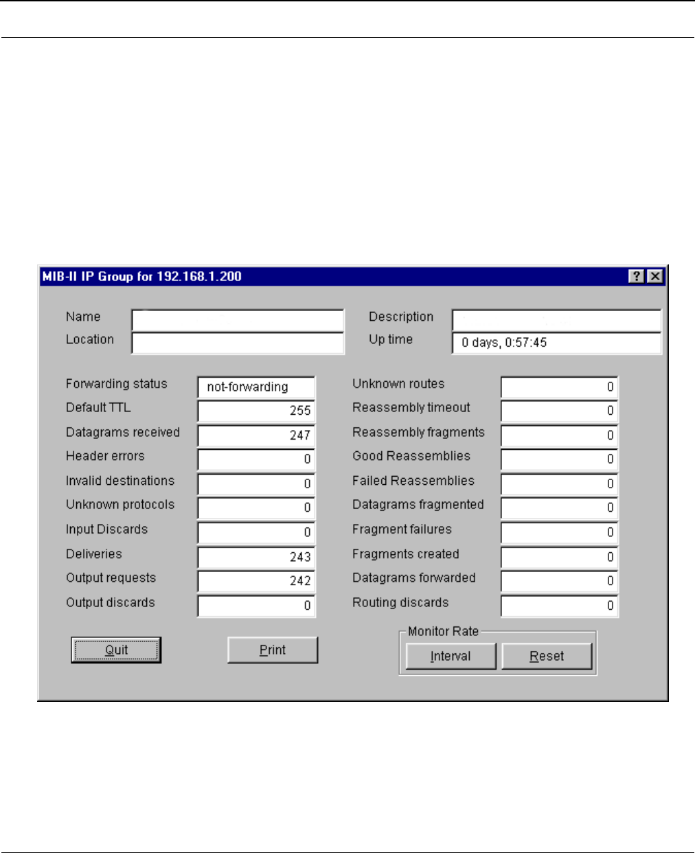
SPEEDLAN 8500 Series Installation and Operation User Guide
SNMP Monitoring 11-17
•Traps
The total number of SNMP Trap PDUs generated by the SNMP protocol entity.
•Authentication Failure Traps
Indicates whether the SNMP agent process is permitted to generate authentication-failure
traps.
IP Monitor
The IDU keeps the standard SNMP MIB II statistics on IP type protocols as indicated below.
•Forwarding Status
Indicates whether this entity is acting as an IP gateway in respect to the forwarding of data-
grams received by, but not addressed to this entity. IP gateways forward datagrams, and IP
hosts do not (except those source-routed via the host). Note that for some managed nodes,
this object may take on only a subset of the possible values.

SPEEDLAN 8500 Series Installation and Operation User Guide
11-18 SNMP Monitoring
•Default TTL
The default value inserted into the Time-To-Live field of the IP header of datagrams
originated at this entity, whenever a TTL value is not supplied by the transport-layer
protocol.
•Datagrams received
The total number of IP datagrams received by the host.
•Header errors
The number of input datagrams discarded due to errors in their IP headers, including bad
checksum errors, version-number mismatch, other format errors, time-to-live exceeded,
errors discovered in processing their IP options, etc.
• Invalid destinations
The number of input datagrams discarded because the IP address in their IP header's
destination field was not a valid address for this entity to receive. This count includes invalid
addresses (i.e., 0.0.0.0) and addresses of unsupported classes (i.e., Class E). For entities
which are not IP gateways and therefore do not forward datagrams, this counter includes
datagrams discarded because the destination address was not a local address.
•Unknown protocols
The number of locally-addressed datagrams received successfully but discarded because of
an unknown or unsupported protocol.
•Input Discards
The number of input IP datagrams for which no problems were encountered to prevent their
continued processing, but which were discarded anyway (e.g., for lack of buffer space).
Note that this counter does not include any datagrams discarded while awaiting re-
assembly.
•Deliveries
The total number of input datagrams successfully delivered to IP user-protocols.
•Output requests
The total number of IP datagrams that are user-protocols (including ICMP) supplied to IP in-
requests for transmission. Note that this counter does not include any datagrams counted in
Datagrams forwarded.
•Output discards
The number of output IP datagrams for which no problem was encountered to prevent their
transmission to their destination, but which were discarded anyway (e.g., for lack of buffer
space). Note that this counter would include datagrams counted in Datagrams forwarded if
any such packets met this (discretionary) discard criterion.

SPEEDLAN 8500 Series Installation and Operation User Guide
SNMP Monitoring 11-19
•Unknown routes
The number of IP datagrams discarded because no route could be found to transmit them
to their destination. Note that this counter includes any packets counted in Datagrams
forwarded which meet this `no-route'criterion, as well as any datagrams which a host
cannot route because all of its default gateways are down.
•Reassembly timeout
The maximum number of seconds that received fragments are held while they are awaiting
reassembly at this entity.
•Reassembly fragments
The number of IP datagrams received which needed to be reassembled at this entity.
•Good Reassemblies
The number of IP datagrams successfully reassembled.
•Failed Reassemblies
The number of failures detected by the IP reassembly algorithm (for whatever reason - timed
out, errors, etc.). Note that this is not necessarily a count of discarded IP fragments since
some algorithms (notably the algorithm in RFC 815) can lose track of the number of
fragments by combining them as they are received.
•Datagrams fragmented
The number of IP datagrams that have been successfully fragmented at this entity.
•Fragment failures
The number of IP-datagram fragments that have been discarded because they needed to be
fragmented at this entity but could not be because the datagram's "don't fragment" flag was
set.
•Fragments created
The number of IP-datagram fragments that have been generated as a result of
fragmentation at this entity.
•Datagrams forwarded
The number of input datagrams for which this entity was not their final IP destination, as a
result of which an attempt was made to find a route to forward them to that final
destination. In entities which do not act as IP gateways, this counter will include only those
packets which were Source-Routed via this entity, and for which Source-Route option
processing was successful.
•Routing discards
The number of routing entries which were chosen to be discarded even though they were
valid. One possible reason for discarding such an entry could be to free up buffer space for
other routing.
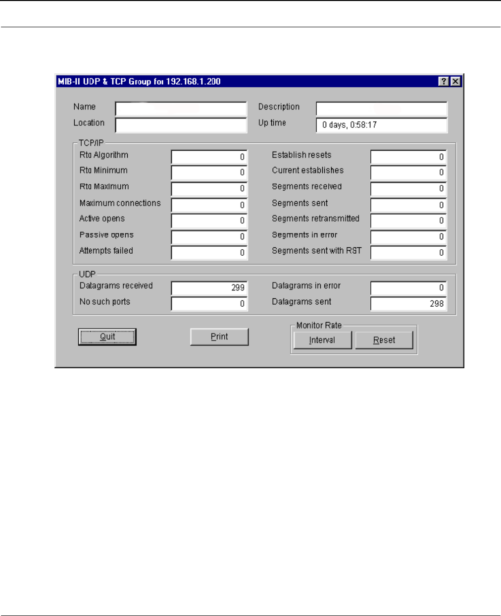
SPEEDLAN 8500 Series Installation and Operation User Guide
11-20 SNMP Monitoring
IP/TCP/UDP Monitor
The IDU keeps the standard TCP/UDP statistics on IP protocols as indicated below.
TCP
•Rto Algorithm
The algorithm used to determine the timeout value used for retransmitting unacknowledged
octets, which can be: "other" - none of the following; "constant" - a constant rto; "rsre" - MIL-
STD-1778, Appendix B; "vanj" - Van Jacobson's algorithm.
•Rto Minimum
The minimum value permitted by a TCP implementation for the retransmission timeout,
measured in milliseconds. More refined semantics for objects of this type depend upon the
algorithm used to determine the retransmission timeout. In particular, when the timeout
algorithm is "rsre", an object of this type has the semantics of the LBOUND quality
described in RFC 793.

SPEEDLAN 8500 Series Installation and Operation User Guide
SNMP Monitoring 11-21
•Rto Maximum
The maximum value permitted by a TCP implementation for the retransmission timeout,
measured in milliseconds. More refined semantics for objects of this type depend upon the
algorithm used to determine the retransmission timeout. In particular, when the timeout
algorithm is rsre, an object of this type has the semantics of the LBOUND quality described
in RFC 793.
•Maximum connections
The limit on the total number of TCP connections the entity can support. In entities where
the maximum number of connections is dynamic, this object should contain the value -1.
•Active opens
The number of times TCP connections have made a direct transition to the SYN-SENT state
from the CLOSED state.
•Passive opens
The number of times TCP connections have made a direct transition to SYN-SENT state
from the LISTEN state.
•Attempts failed
The number of times TCP connections have made a direct transition to the CLOSED state
from either the SYN-SENT state or the SYN-RCVD state, plus the number of times TCP
connections have made a direct transition to the LISTEN state from the SYN-RCVD state.
•Establish resets
The number of times TCP connections have made a direct transition to the closed state from
either the ESTABLISHED state or the CLOSE-WAIT state.
•Current establishes
The number of TCP connections for which the current state is either ESTABLISHED or
CLOSE-WAIT.
•Segments received
The total number of segments received, including those received in error. This count
includes segments received on currently established connections.
•Segments sent
The total number of segments sent, including those on current connections but excluding
those containing only retransmission octets.
•Segments retransmitted
The total number of segments retransmitted -- that is, the number of TCP segments
transmitted containing one or more previously transmitted octets.
•Segments in error
The total number of segments received in error (i.e., with bad TCP checksums).
•Segment sent with RST
The number of TCP segments sent containing the RST flag.

SPEEDLAN 8500 Series Installation and Operation User Guide
11-22 SNMP Monitoring
UDP
•Datagrams received
The total number of UDP datagrams delivered to UDP users.
•No such port
The total number of received UDP datagrams for which there was no application at the des-
tination port.
•Datagrams in error
The number of received UDP datagrams that could not be delivered for a reason other than
the lack of an application at the destination port.
•Datagrams sent
The total number of UDP datagrams sent from this entity.
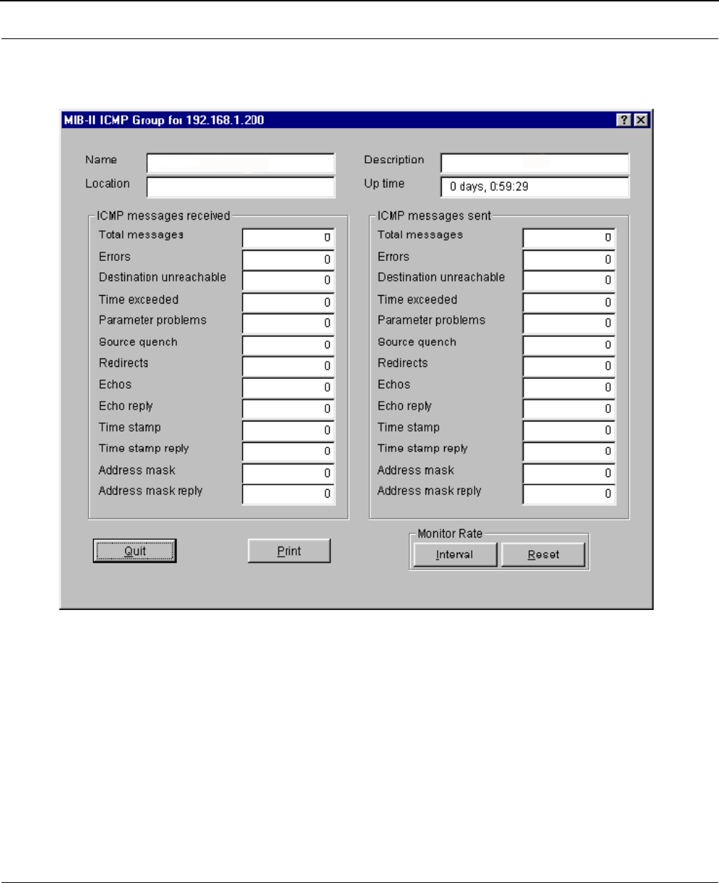
SPEEDLAN 8500 Series Installation and Operation User Guide
SNMP Monitoring 11-23
ICMP Monitor
The IDU keeps the standard statistics on ICMP as indicated below.
ICMP Messages Received
•Total me ss ag es
The total number of ICMP messages which the entity received. Note that this counter
includes all those counted by received Errors.
•Errors
The number of ICMP messages which the entity received but determined as having ICMP-
specific errors (bad checksums, bad length, etc).
•Destination unreachable
The number of ICMP Destination Unreachable messages received.

SPEEDLAN 8500 Series Installation and Operation User Guide
11-24 SNMP Monitoring
•Time exceeded
The number of ICMP Time Exceeded messages received.
•Parameter problems
The number of ICMP Parameter Problem messages received.
•Source quench
The number of ICMP Source Quench messages received.
•Redirects
The number of ICMP Redirect messages received.
•Echoes
The number of ICMP Echo (request) messages received.
•Echo reply
The number of ICMP Echo Reply messages received.
•Time stamp
The number of ICMP Timestamp (request) messages received.
•Time stamp reply
The number of ICMP Timestamp Reply messages received.
•Address mask
The number of ICMP Address Mask (request) messages received.
•Address mask reply
The number of ICMP Address Mask Reply messages received.
ICMP Messages Sent
•Total me ss ag es
The total number of ICMP messages which this entity attempted to send. Note that this
counter includes all those counted by ICMP out Errors.
•Errors
The number of ICMP messages which this entity did not send due to problems discovered
within ICMP, such as a lack of buffers. This value does not include errors discovered outside
the ICMP layer such as the inability of IP to route the resultant datagram. In some imple-
mentations there may be no types of errors which contribute to this counter's value.
•Destination Unreachable
The number of ICMP Destination Unreachable messages sent.
•Time exceeded
The number of ICMP Time exceeded messages sent.
•Parameter problems
The number of ICMP Parameter Problem messages sent.

SPEEDLAN 8500 Series Installation and Operation User Guide
SNMP Monitoring 11-25
•Source quench
The number of ICMP Source Quench messages sent.
•Redirects
The number of ICMP Redirect messages sent.
•Echoes
The number of ICMP Echo (request) messages sent.
•Echo Reply
The number of ICMP Echo Reply messages sent.
•Time Stamp
The number of ICMP Time Stamp (request) messages sent.
•Time Stamp Reply
The number of ICMP Time Stamp Reply messages sent.
•Address mask
The number of ICMP Address Mask (request) messages sent.
•Address mask reply
The number of ICMP Address Mask Reply messages sent.

SPEEDLAN 8500 Series Installation and Operation User Guide
11-26 SNMP Monitoring
Notes:___________________________________________________
______________________________________________________
______________________________________________________
______________________________________________________
______________________________________________________
______________________________________________________
______________________________________________________
______________________________________________________
______________________________________________________
______________________________________________________
______________________________________________________
______________________________________________________
______________________________________________________
______________________________________________________
______________________________________________________
______________________________________________________
______________________________________________________
______________________________________________________
______________________________________________________
______________________________________________________
______________________________________________________
______________________________________________________
______________________________________________________

Chapter 12
Tables
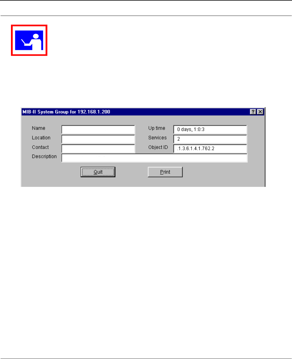
SPEEDLAN 8500 Series Installation and Operation User Guide
12-2 Tables
To open the tables, choose the appropriate selection by choosing Monitor (on the SPEEDLAN
Configurator)+ Advanced + your selection
System Information
System Information displays information about the IDU's Management Information Base Group. The
IDU keeps the standard SNMP MIB II statistics on system-related information as indicated below.
• Name
An administratively-assigned name for this managed node. By convention, this is the node's
fully-qualified domain name.
•Location
The physical location of this node (e.g., `telephone closet, 3rd').
•Contact
The name/position of the contact person for this managed node, together with information
on how to contact this person.
•Description
This value contains the full name and version identification of the system's hardware type,
software operating system, and network software.
•Up time
The time since the network-management portion of the system was last re-initialized.
•Services
The number of services handled by the IDU.
•Object ID
The identification number of the IDU.
TIP
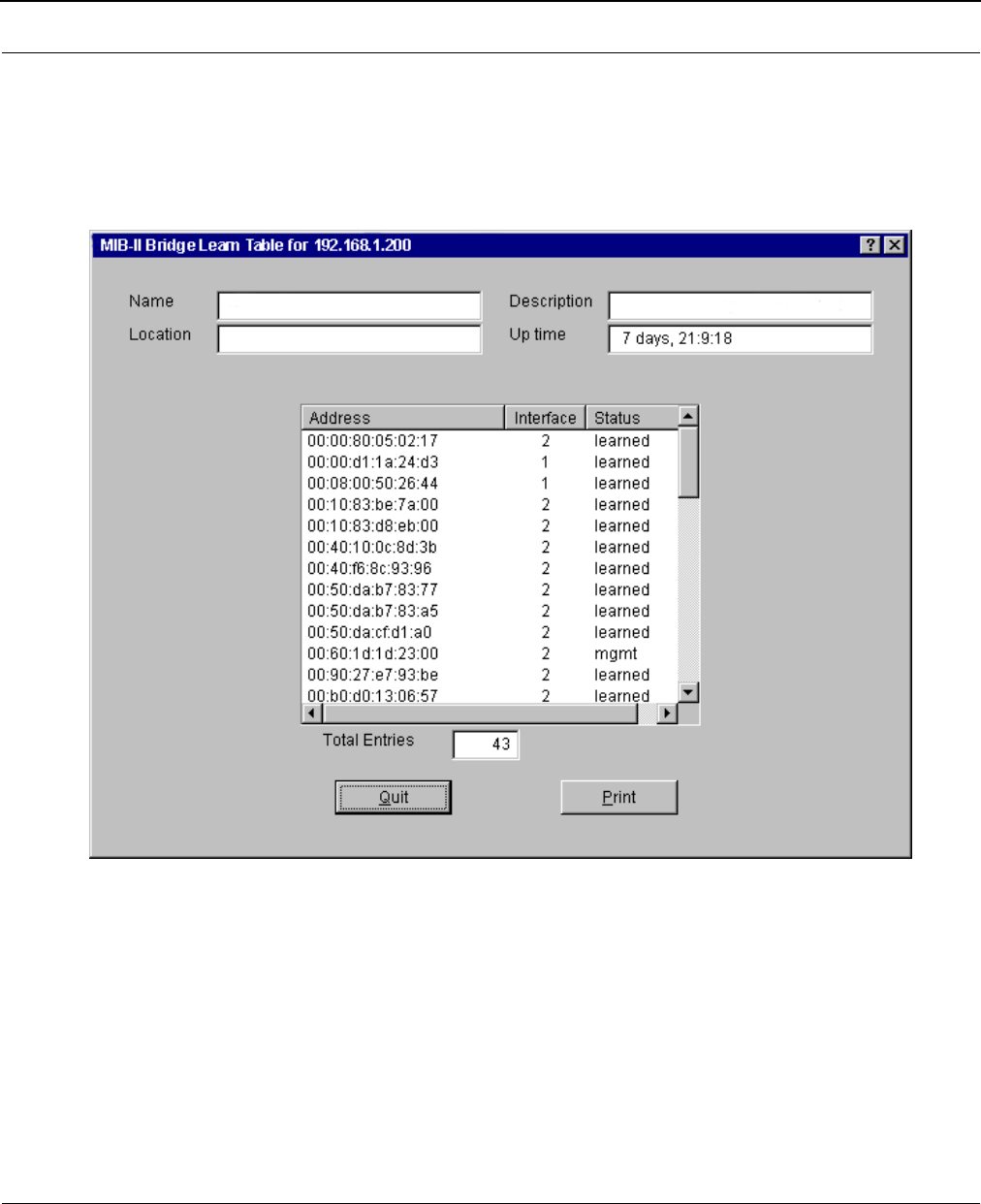
SPEEDLAN 8500 Series Installation and Operation User Guide
Tables 12-3
IDU Learn Table
This table contains information about unicast entries for which the IDU has forwarding and/or
filtering information. This information is used by the transparent bridging function to determine how
to propagate a received frame.
•Address
A unicast MAC address for which the IDU has forwarding and/or filtering information.
•Interface
Either the value 0 (zero), or the interface number on which a frame has been seen. A value
of 0 (zero) indicates that the interface number has not been learned but the IDU does have
some forwarding/filtering information about this address.
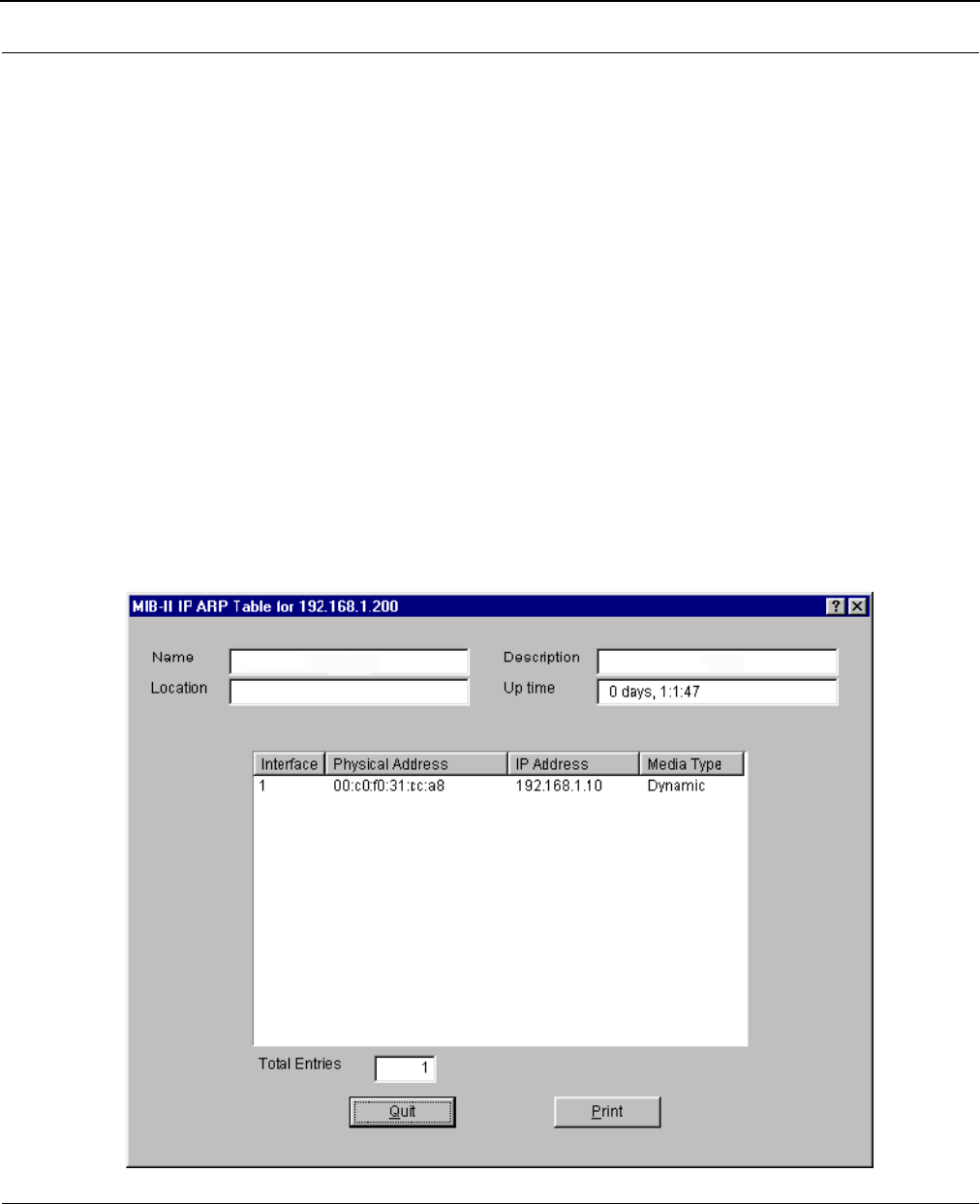
SPEEDLAN 8500 Series Installation and Operation User Guide
12-4 Tables
•Status
The status of this entry. The meanings of the values are:
•other
None of the following.
•invalid
This entry is no longer valid, but has not been flushed from the table yet.
•learned
This entry was learned, and is being used.
•self
This entry represents one of the IDU's addresses. The interface value indicates which of
the IDU's interfaces has this address.
•mgmt
This entry is also the value of an existing instance in the static table.
IP ARP Table
The IP ARP Table contains the IP-Address-to-`physical'-(MAC)-Address equivalences.

SPEEDLAN 8500 Series Installation and Operation User Guide
Tables 12-5
•Interface
The interface on which this entry is effective.
•IP Physical Address
The media-dependent `physical' (MAC) address. An example would be the MAC address of
the Ethernet interface.
•IP Address
The IP address corresponding to the media-dependent `physical' (MAC) address.
•Media Type
The type of mapping:
•other
none of the following
•invalid
an invalidated mapping
•dynamic
a mapping that can change with circumstances
•static
a mapping which does not change
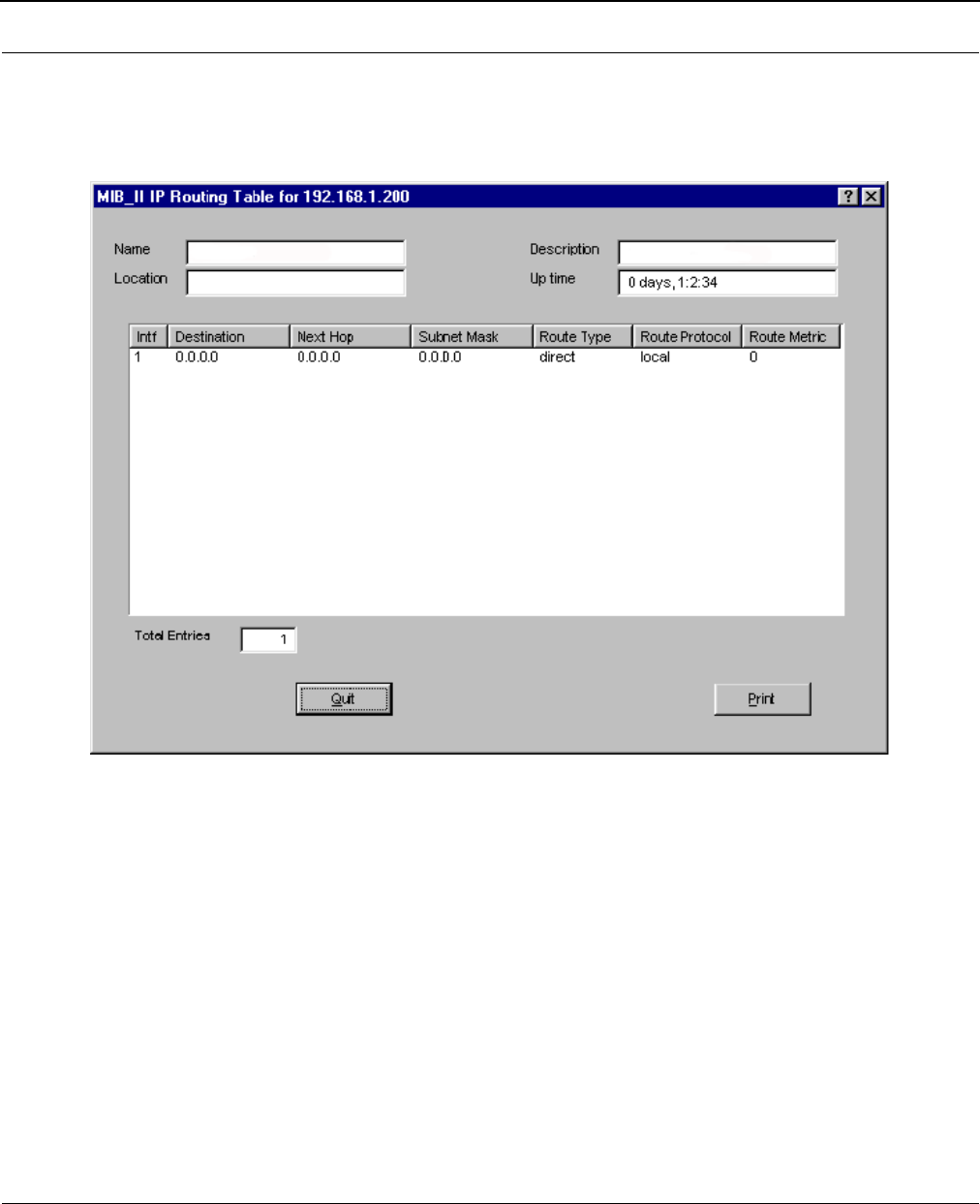
SPEEDLAN 8500 Series Installation and Operation User Guide
12-6 Tables
IP Route Table
The IDU keeps the standard SNMP MIB II statistics on the IP routing table, which contains an entry
for each route presently known.
•Intf
The local interface through which the next hop of this route should be reached.
•Destination
The destination IP address of this route. An entry with a value of 0.0.0.0 is considered a
default route. Multiple routes assigned to a single destination can appear in the table, but
access to such multiple entries is dependent on the table-access mechanisms defined by the
network-management protocol in use.
•Next Hop
The IP address of the next hop of this route.

SPEEDLAN 8500 Series Installation and Operation User Guide
Tables 12-7
•Subnet Mask
Indicates the mask to be a logical-ANDed with the destination address before being com-
pared to the value in the Destination field. For systems that do not support arbitrary subnet
masks, an agent constructs the value of the Subnet Mask by determining whether the value
of the correspondent Destination field belongs to a Class A, B, or C network.
•Route Type
Type of route. This can be:
•other
none of the following
•invalid
an invalidated route
•direct
route to directly connected (sub-)network
•indirect
route to a non-local host/network/subnetwork.
•Route Protocol
The routing mechanism by which this route was learned. Inclusion of values for gateway-
routing protocols is not intended to imply that hosts should support those protocols. The
values are as follows:
•other
none of the following
•local
non-protocol information
•netmgmt
entries set via a network-management protocol
•icmp
obtained via ICMP (e.g., ICMP `redirect')
•egp
all gateway-routing protocols
•ggp
all gateway-routing protocols
• Route Metric
The primary routing metric for this route. The semantics of this metric are determined by the
routing protocol specified in the route's Route Protocol value. If this metric is not used, its
value should be set to -1.
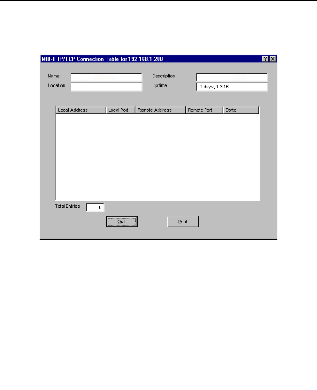
SPEEDLAN 8500 Series Installation and Operation User Guide
12-8 Tables
IP/TCP Connection Table
This table reports the states of the TCP connections and contains the following fields as indicated
below.
•Local Address
The local IP address for this TCP connection. In the case of a connection in the listen state
which is willing to accept connections for any IP interface associated with the node, the
value 0.0.0.0 is used.
•Local Port
The local port number for this TCP connection.
•Remote Address
The remote IP address for this TCP connection.
•Remote Port
The remote port number for this IP connection.
•State
The state of this TCP connection, which can be one of the following: closed, listen, synSent,
synReceived, established, finWait1, finWait2, closeWait, LastAck, closing, timeWait,
deleteTCB.
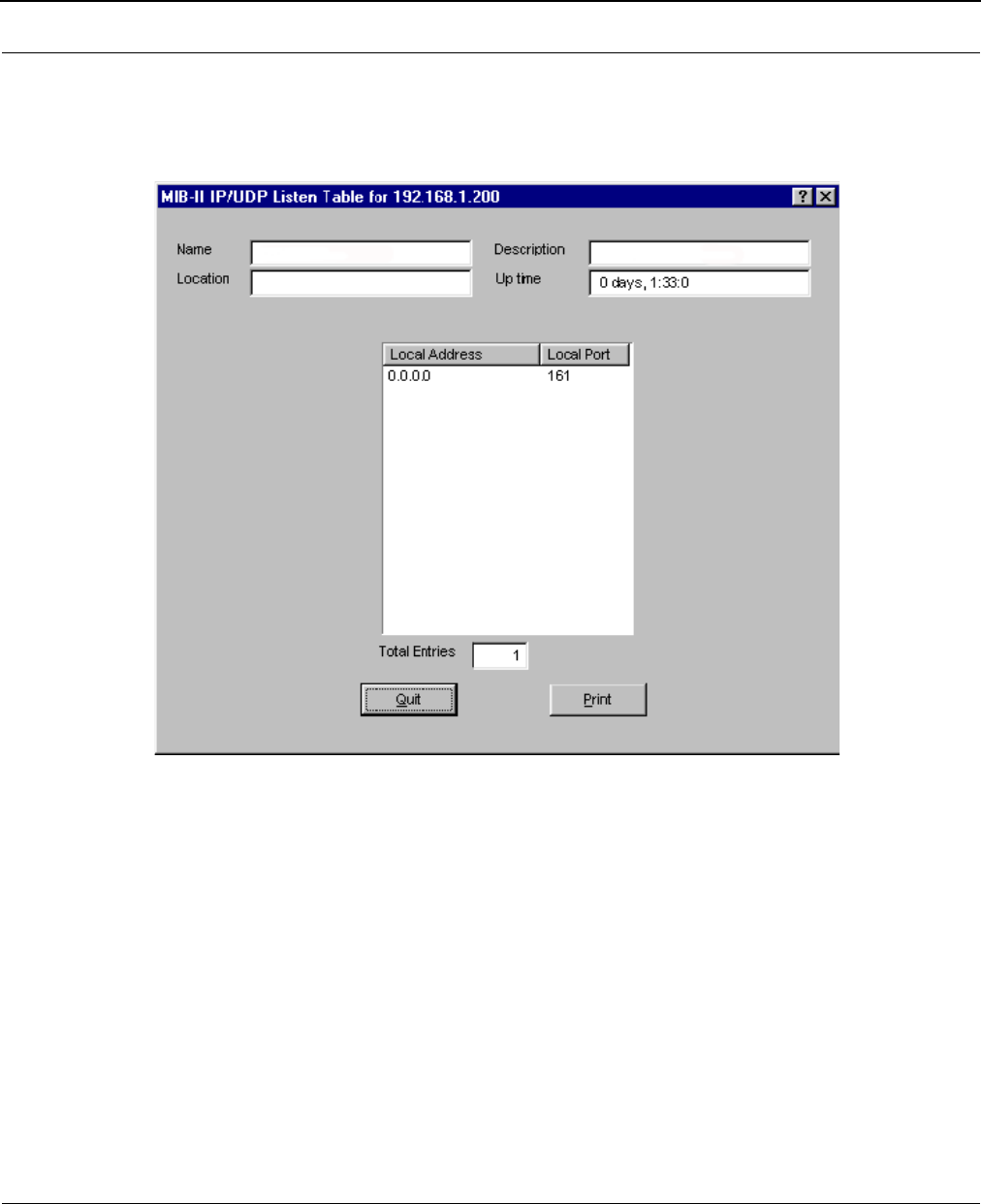
SPEEDLAN 8500 Series Installation and Operation User Guide
Tables 12-9
IP/UDP Listener Table
This table reports the states of the UDP connections and contains the following fields as indicated
below.
•Local Port
The local port number for this UDP connection.
•Local Address
The local IP address for this UDP connection. In the case of a connection in the listen state
which is willing to accept connections for any IP interface associated with the node, the
value 0.0.0.0 is used.
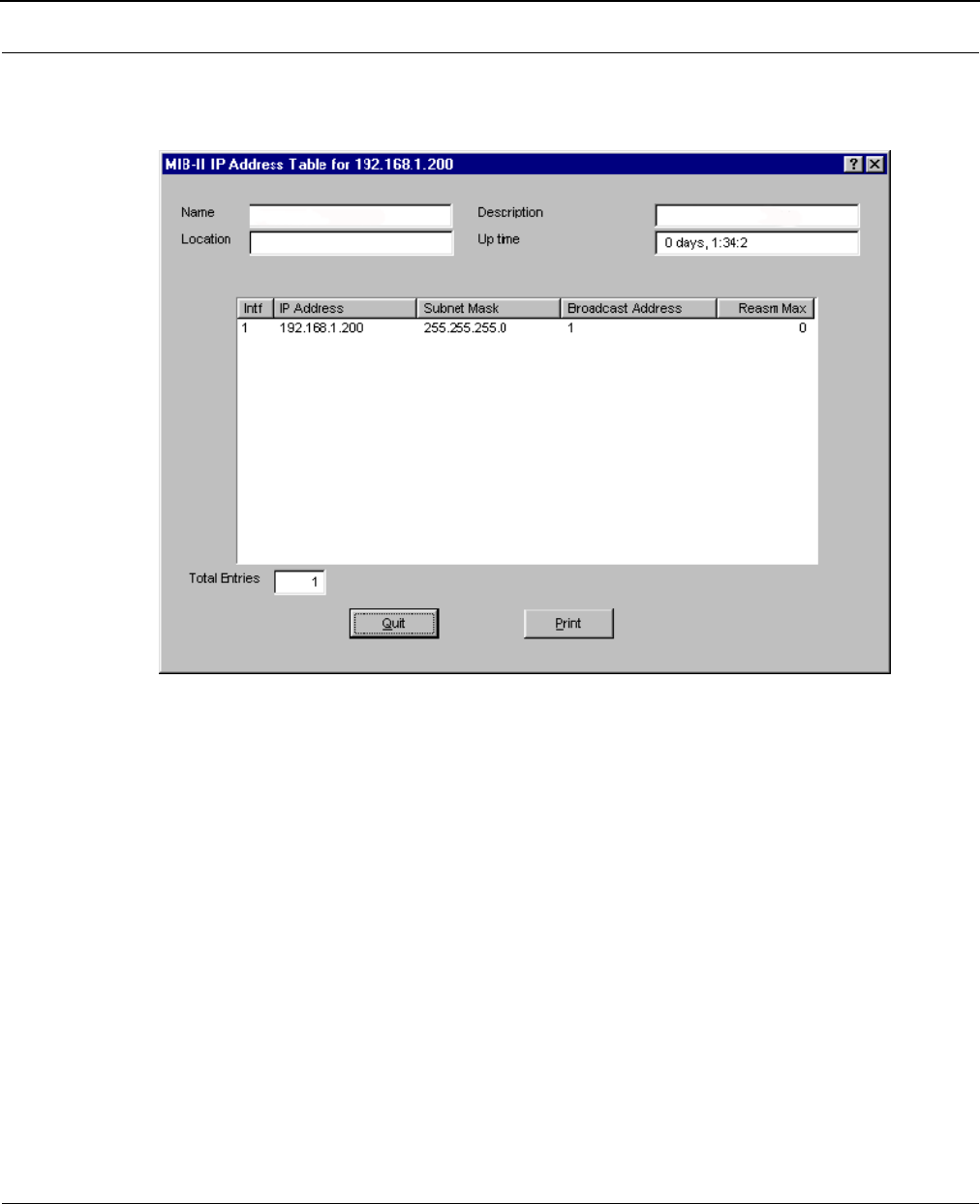
SPEEDLAN 8500 Series Installation and Operation User Guide
12-10 Tables
Local IP-Address Table
The table displays addressing information that is relevant to the entity’s IP addresses.
•Intf
The interface to which the entry is applicable.
•IP Address
The IP address to which this entry's addressing information pertains.
•Subnet Mask
The subnet mask associated with the IP address of this entity. The value of the mask is an IP
address with all the network bits set to 1 and all the host bits set to 0.
• Broadcast Address
The value of the least-significant bit in the IP broadcast address used for sending datagrams
on the logical interface associated with the IP address of this entry. For example, when the
Internet standard all-ones broadcast address is used, the value will be 1. This value applies
to both the subnet- and network-broadcast address used by the entity on this logical
interface.
• Reasm Max
The size of the largest IP datagram which this entity can re-assemble from incoming IP
fragmented datagrams received on this interface.

Chapter 13
Analyzing Wireless Equipment
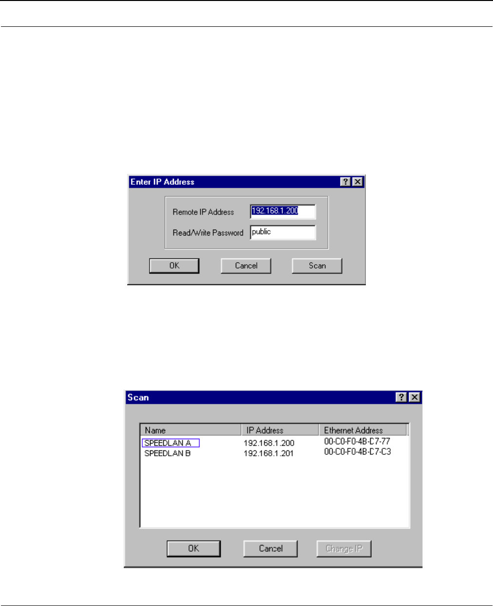
SPEEDLAN 8500 Series Installation and Operation User Guide
13-2 Analyzing Wireless Equipment
Select Another Device
Use this feature to select another pair of IDUs, routers or remote IDUs. This is a helpful
feature when running a wireless link test. Note that you must scan the IDU before selecting another
device.
To select another wireless device, do the following:
1From the Analyze, menu, choose Select Another Device.
2The Enter IP Address dialog box appears.
3Verify the information in the Enter IP Address dialog box and click Scan. This opens the
Scan dialog box, which allows you to select the new pair.
4Select the pair and click OK. Verify the Remote and IP Address and Read/Write Password in
the Enter IP Address dialog box. Then, click OK. The SPEEDLAN Configurator confirms that
the device was located. Click OK again. You have successfully selected another device and
test the pair as needed.
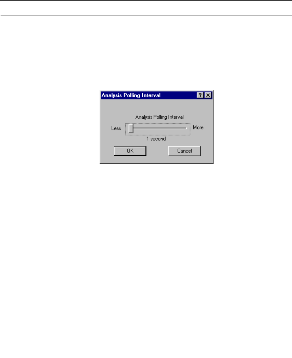
SPEEDLAN 8500 Series Installation and Operation User Guide
Analyzing Wireless Equipment 13-3
Analysis Polling Interval
Use the feature to set the rate at which the SPEEDLAN Configurator polls the IDU during analysis.
Note that you must scan the IDU before setting the interval rate.
To set the rate of the interval, do the following:
1From the Analyze menu, choose Analysis Interval. The Analysis Polling Interval dialog box
appears.
2Use your mouse and move the interval to the rate of your specification. Then, click OK.
Wireless Link Test
Run the wireless link test to verify that your equipment is communicating properly at the RF level. This
test can be performed when you are performing a bench test for the IDU or from the actual link. This
process will help you during your performance evaluation. If you already scanned the IDU (or IDU
pair), skip to Step 5.
To initialize a link test, do the following:
1From the File menu, choose Open Remote Config. Then, click Scan.
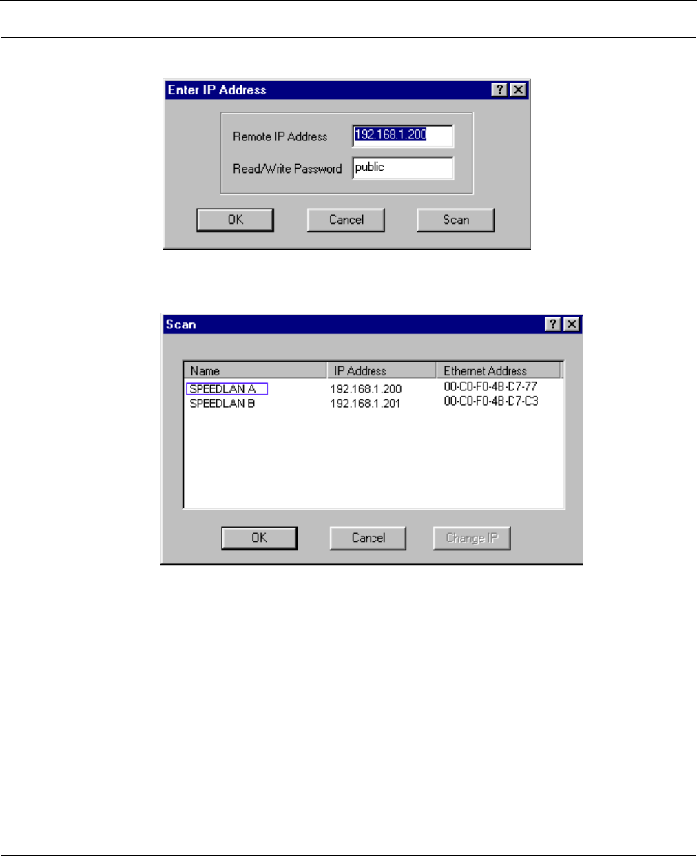
SPEEDLAN 8500 Series Installation and Operation User Guide
13-4 Analyzing Wireless Equipment
2Select the name of the IDU that you want to initialize.
3Click OK to confirm that the IP address is correct.
4Click OK again. You should receive the following message: "Configuration has been read
from the IDU (ip xxx.xxx.xxx.xxx)."
5From the Analyze menu, choose Wireless Link Test. The Select a Remote Link Partner (for
your IDU pair) appears.
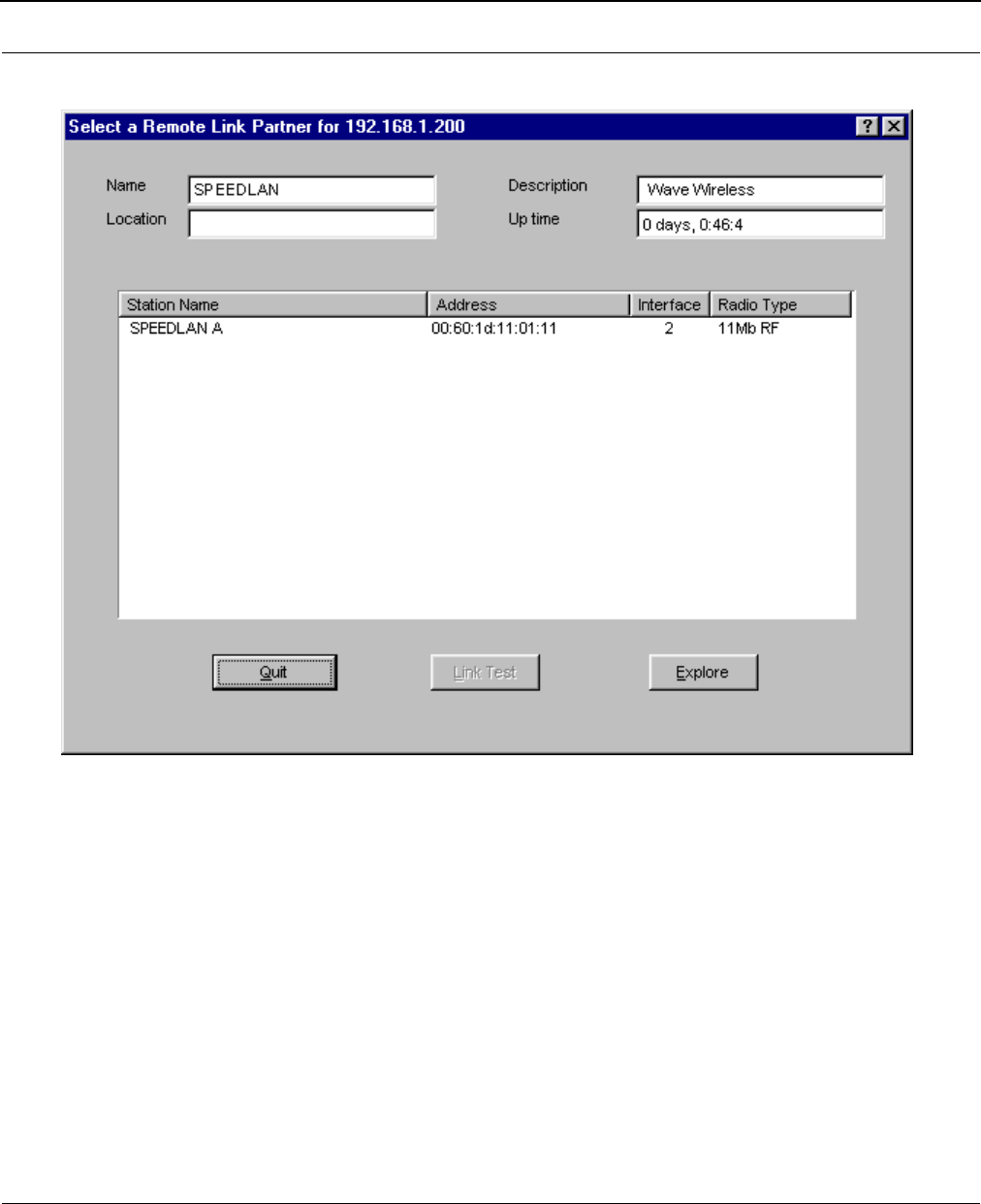
SPEEDLAN 8500 Series Installation and Operation User Guide
Analyzing Wireless Equipment 13-5
6 Select the Station Name or (name of IDU pair) of the IDU or clients that you want to test.
Description of Wireless Link Test Window
•Name
Name of the initiator station of the wireless link test.
•Description
Initiator station IDU type and firmware version.
•Location
Location of the initiator station. (This is only available if entered in the SNMP Setup options
by selecting SNMP Setup from the Setup menu.)
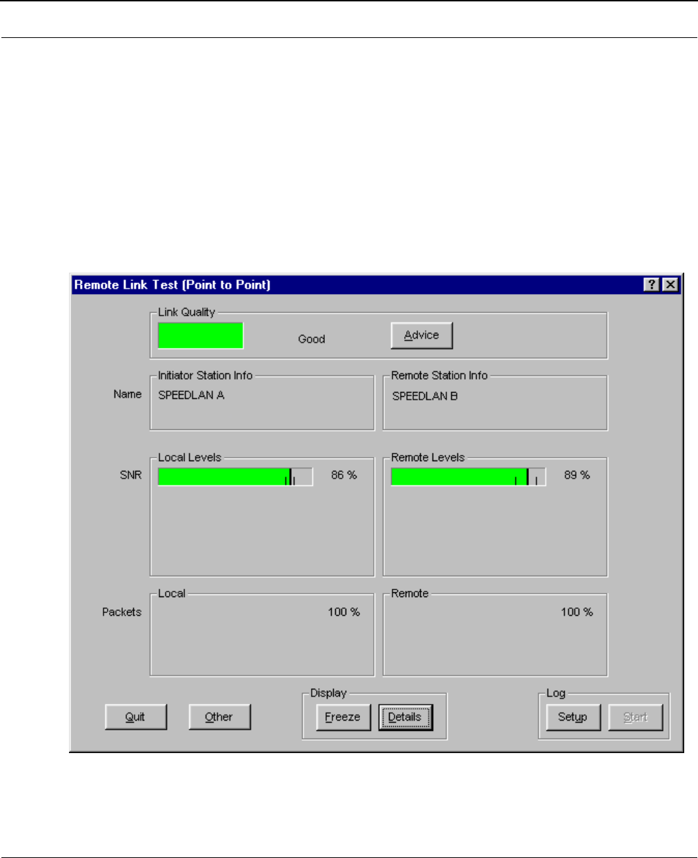
SPEEDLAN 8500 Series Installation and Operation User Guide
13-6 Analyzing Wireless Equipment
•Up Time
Amount of time that the initiator station has been running since the last reboot.
•Station Name
Name of the remote partners that are currently communicating with the initiator station.
•Address
MAC address of the interface of the remote partner.
•Interface
The interface of the initiator station that the remote partner is communicating to.
•Radio Type
The type of radio specified in the Remote Partner.
7Next, click Link Test. The wireless link test should begin as displayed on the next page.
Note: For more detailed information, click Details (located near the bottom of the Remote
Link Test dialog box).

SPEEDLAN 8500 Series Installation and Operation User Guide
Analyzing Wireless Equipment 13-7
Important Wireless Statistics
Some of the most important wireless statistics are the following:
•Link Quality
This displays the quality of the link.
•Green = Good activity
•Yellow = Acceptable activity
•Red = Poor activity
•SNR (Signal-to-Noise Ratio)
The ratio of the standard description of the signal to the standard deviation of the noise.
•Signal
Again, the higher the signal level, the better. In order for the link to be successful, you
should have a signal level approximately 20 points higher than the noise.
•Noise
Since the spread spectrum signals run clearly, the noise level is usually very low. The lower
the noise, the better.
•Packets
This displays the percentage of test packets successfully received at each end. A higher per-
centage is better.
If you are loosing a large percentage of packets, try realigning the antenna or
changing its polarization (keeping in mind the antenna polarization must be the same
at both ends of the wireless link. Then, run the wireless link test again.
•Log
You can log the results of the link test into an ASCII text file. You can run the performance
over time and create a graphic to view the past to current results.
8To exit this test, click Quit. Rerun the wireless link test after you have configured each IDU
or implemented any antenna alignments to verify that all equipment is communicating suc-
cessfully.
9Fine tune antennas to maximize signal level at each site and repeat the link test again to
confirm good performance.
TIP

SPEEDLAN 8500 Series Installation and Operation User Guide
13-8 Analyzing Wireless Equipment
Antenna Alignment
Use this feature to continuously broadcast packets in order to test optimum antenna alignment. Note
that you must scan the IDU before running this test.
WARNING! This test will broadcast a large amount of test packets across the wireless link. It will
interfere with normal wireless network operation.
To run the antenna alignment test, do the following:
1From the Analyze menu, choose Antenna Alignment. The Antenna Alignment dialog box
appears.
2 Enter the following information:
•Interface to run test on
Each IDU contains several network interfaces to which it may be connected. The net-
work interfaces are numbered (i.e., 1,2,3...). The number of interface can be found by
choosing Interface Setup from the Setup menu.
•Seconds to run test (0=Stop)
This is simply the length (in seconds) of the antenna alignment test.
•Transmit Rate
This is the speed (measured in Hertz) of the signal transmission.

Glossary for Standard Data
Communications

SPEEDLAN 8500 Series Installation and Operation User Guide
Glossary-2
Glossary for Standard Data Communications
Alignment
In order to create a successful link, all related equipment should be associated to its respective attachments or equipment.
Amplitude
The magnitude of a waveform when measured from the mid-point to the peak of the wave.
Analog
A signal in the form of a continuously varying quantity such as voltage, frequency or phase.
Antenna
Device used to concentrate and direct the energy of a signal into a tight beam. Parabolic or dish, grid, and Yagi are dif-
ferent varieties of antennas.
Antenna Gain
The ratio of the power radiated by an antenna in a specific direction versus the power required to produce this same
strength if an isotropic antenna were used.
Attenuation
The measure of the loss of power in a microwave signal as it travels between two points. It is measured in decibels (dB).
Attenuator
Attenuators simulate antennas during bench tests.
Azimuth
This is the direction of antenna pointing relative to true north.
Band
A portion of the electromagnetic frequency spectrum.
Bandwidth
The range of frequencies over which a device will transmit information.
Bit
An abbreviation for binary digits.

SPEEDLAN 8500 Series Installation and Operation User Guide
Glossary-3
Bit Error Rate
A measure of the number of errors in a digital transmission. Typically given as an exponential number that represents the
ratio of errors to total bits. Example: 1E-03 = 0.001 = 1.0 x 10⁻³ and 1.0E-6 = 0.000001 = 1.0 x 10⁻³. A single ele-
ment in a binary code. A measure of the number of errors in a digital transmission. Typically given as an exponential
number that represents the ratio of errors to total bits. Example: 1E-03 = 0.001 = 1.0 x 10⁻³ and 1.0E-6 = 0.000001
= 1.0 x 10⁻³.
IDU
The function of a IDU is to connect separate networks together. This device operates at the DataLink Layer of the OSI
model. IDUs connect different network types (such as Fast Ethernet and Ethernet) or networks of the same type. IDUs allow
only necessary traffic to pass through the designated segments. When the IDU receives a packet, the IDU determines the
destination and source segments. If the segments are the same, the packet is dropped, or filtered. If the segments are dif-
ferent, then the packet is “forwarded” to the correct segment. Additionally, IDUs do not forward bad or misaligned pack-
ets. IDUs are also called “store-and-forward” devices because they look at the whole Ethernet packet before making
filtering or forwarding decisions. Filtering packets, and regenerating forwarded packets enables bridging technology to
split a network into separate collision domains.
IDU
This device is a combination of a router and a IDU in one product.
Byte
A data unit consisting of eight bits.
Cable
A transmission medium of copper wire or optical fiber wrapped in a protective cover.
Channel
A specific band of frequencies designated for a specific purpose; the data path between two nodes.
Channel Service Unit/Data Service Unit (CSU/DSU)
Manages digital transmission and monitors signals for problems. Performs many functions similar to a modem with the
exception of converting digital signals to/from analog since the end device and transmission facility are both digital.
Channel Spacing
The amount of space signals can flow through.

SPEEDLAN 8500 Series Installation and Operation User Guide
Glossary-4
Class
Understanding this methodology is difficult, even for customers. Therefore, let’s explain this in easier terms. The first octet
(or octets) defines the “class” (indicated by the word “net” in this example) of the address, which is the only method to tell
the size of the network (how big) and where the internet address belongs. The remaining octets indicate availability for net-
work equipment (i.e., computer or other network equipment). The three main classes are: Class A, Class B, and
Class C.
•Class A: Net, Node, Node, Node 255.0.0.0 (last three octets are available for equipment)
•Class B: Net, Net, Node, Node 255.255.0.0 (last two octets are available for equipment)
•Class C: Net, Net, Net, Node 255.255.255.0 (last octet is available for equipment)
Coaxial Cable
A type of transmission line consisting of a center conductor wire surrounded by insulation that is in turn surrounded by a
conductive shield made of metal foil or wire braid. Often used to connect the RF unit and modem unit of a wireless
system.
Code Division Multiple Access (CDMA)
A system in which all users occupy the same bandwidth. Uncorrelated codes are used to allow for higher bandwidth occu-
pancy. This is also known as the spread spectrum system.
Common Management Information Protocol (CMIP)
A network management protocol that is consistent with an Open Systems Interconnection (OSI) network communication
model.
Company name
This is the name of the company that owns or maintains the radio given to the terminal.
Console
This device allows you to communicate through the Telnet client to access the configuration software.
Crimp
Crimp the connector to secure the conductors.
Customer Premise Equipment (CPE)
Any equipment located at the customer site. Usually in reference to those that are connected to a network.
Data Communication Equipment (DCE)
A definition of an interface standard that determines how it is connected to another device. For most modems, it resolves
issues of interface between Data Terminal Equipment (DTE) and the network.

SPEEDLAN 8500 Series Installation and Operation User Guide
Glossary-5
Data Terminal Equipment (DTE)
Hardware that provides for data communications. See also DCE above.
dBm
Decibels (dB) relative to 1 milliwatt.
dBw
Decibels (dB) relative to 1 watt.
Decibel (dB)
The standard unit of measurement for expressing relative signal power. It is dimensionless and is instead referenced to a
certain level.
Diffraction
The distortion of a wave as it is partially obstructed by an object in its path.
Digital Signal Processor (DSP)
A specialized computer chip designed to perform speedy and complex operations on digitized waveforms.
Direct Sequence (DS)
A type of spreading technique that multiplies a higher rate PN code to the signal in order to spread the energy of the nar-
row band signal over a much wider bandwidth for transmission.
Direct Sequence Speed Spectrum (DSSS)
DSSS may be seen as the result of two processes. Data is multiplied with a higher rate digital sequence (spreading code).
The sequence has many “chips” for every data bit. The resultant signal modulates the RF carrier.
E1
European Standard also used in South American nations, among others. Speed is 2.048 Mega bits per second (Mbps).
Uses the G.703 data interface.
Elevation
1. Height above sea level. 2. The vertical angle in degrees between the ground and the direction the antenna is pointed.
ESD
Electro-Static Discharge happens when there is a transfer between objects at diverse voltages.

SPEEDLAN 8500 Series Installation and Operation User Guide
Glossary-6
Ethernet
This is the most popular physical layer LAN technology in use today. Other LAN types include Token Ring, Fast Ethernet,
Fiber Distributed Data Interface (FDDI), Asynchronous Transfer Mode (ATM) and Local Talk. Ethernet is popular because it
strikes a good balance between speed, cost and ease of installation. These benefits, combined with wide acceptance in
the computer marketplace, create the ability to support virtually all-popular networks and make Ethernet an ideal network-
ing technology for most computer users today. The Institute for Electrical and Electronic Engineers (IEEE) defines the Ether-
net as IEEE Standard 802.3. This standard defines rules for configuring an Ethernet, as well as specifying how elements in
an Ethernet network interact with one another. By adhering to the IEEE standard, network equipment and network proto-
cols will communicate efficiently.
Ethernet Switch
This device helps expand the Ethernet network. LAN switches can link four, six, ten or more networks together, and have
two basic architectures. This switch “cuts through” and “stores and forwards” as well. This technique takes more time to
examine the entire packet, but it allows the switch to catch certain packet errors and keep them from propagating through
the network. A switch also operates between the DataLink and Network Layer of the OSI model. It reads the MAC address
and will either IDU it to the Physical Layer or route to the Network Layer.
Fade Margin
The difference between the receiver signal input level and the receiver sensitivity. Fade margin is usually considered the
safety factor allowing the system to remain operating under additional forms of attenuation.
Fading
The loss of signal strength due to changes in the atmosphere.
Fault
This section of the browser gives the user a detailed list of alarm activity. Along with the alarm activity, the Event Log also
time stamps an alarm, so the user is able to determine when an event occurred, and at what time the event cleared. The
date and time fields are derived from the time read by the radio on the network time server.
Federal Communications Commission (FCC)
Government organization appointed by the U.S. President that regulates interstate communications (by use of licenses,
standards, rates, etc.).
Firmware
Alterable programs in semitransparent storage (e.g., some type of read-only or flash reprogrammable memory).

SPEEDLAN 8500 Series Installation and Operation User Guide
Glossary-7
Forward Error Correction (FEC)
The ability of a receiving station to correct a transmission error. The transmitter sends redundant information along with
the original bits and the receiver uses this information to find and correct errors. This can increase the throughput of a
data link operation.
Framing
Dividing data for transmission into groups of bits, and adding a header and a check sequence to form a frame.
Frequency
The number of complete cycles per second existing in a waveform. Note that frequency is measured in Hertz (Hz).
Frequency Hopping (FH)
A type of spreading technique using a PN code to change the signal’s frequency between several pre-assigned values
(hopping). Although the signal itself looks like a narrow band signal at any given point in time, it acts like a spread signal
because of the frequency hopping.
Fresnel Zone
An imaginary ellipse surrounding the direct transmission path formed by all the points from which a reflected wave would
have an increased path length of multiple of the transmitted signal’s wavelength. At least 60% of the Fresnel zone must be
unobstructed.
Full Duplex
Independent, simultaneous two-way transmission going in both directions.
Gain
The increase in signal power caused by a device such as a transmitter or antenna.
GHz
GigaHertz. Billions of Hertz.
Ground elevation
This is the approximate mean sea level (AMSL) of the terminal.
Half Duplex
A one-way directional communication line going in both directions. Only one signal can be transmitted or received at a
time

SPEEDLAN 8500 Series Installation and Operation User Guide
Glossary-8
Hertz (Hz)
A unit of measurement equal to one cycle per second.
Hexadecimal (Hex, or H)
A Base-16 numbering system. This means 16 sequential numbers are used as a base unit (i.e., “0-9” and “A-F”).
Hop
A term used to describe a single radio path between two points.
Host
This term is interchangeable with the definition “node,” which means this is a point on the network. The host is also any
device on the network that has two-way communication to any point on the network, as well as the Internet.
Hot-standby
A condition whereby when the primary method of communication goes down, the secondary method instantly takes over.
Hub
This device on a network collects, receives, and repeats data to its forwarded destination on the network. A hub is also
known as a switch.
HyperTerminal
This provides you details of the internal configuration of the ODU. In the HyperTerminal, you can also change the port set-
tings for the modem connection and adjust the settings to make a call.
IDU
Indoor Unit (i.e., Modem Unit).
IF Cable
In an SPEEDCOM system, this is the coaxial cables that connects the modem unit to the RF unit. These cables are termi-
nated with male TNC-type connectors at both ends.
Interface
The standard signal for connecting a microwave system to the connecting equipment.
Interference
Unwanted signals that cause performance degradation or loss of information.

SPEEDLAN 8500 Series Installation and Operation User Guide
Glossary-9
Intermediate Frequency (IF)
The frequency to which a microwave signal is converted to permit signal processing. This range is typically around 70 to
200 MHz.
Internet
This is a system of linked networks that are worldwide in scope and facilitates data communicate service such as remote
login, file transfer, electronic mail, the World Wide Web and newsgroups. With the meteoric rise of demand for connectiv-
ity, the Internet has become the communications highway for millions of users. The Internet was initially restricted to mili-
tary and academic institutions in its infancy, but now it is a full-fledged information channel for any and all forms of
information and commerce. Internet web sites now provide personal, educational, political and economic resources to
every cornet of the planet.
IP Address
This address tells the network how to locate the computers or network equipment connected to it. IP addresses are given
so each computer or equipment on the network contains a unique address.
ISM (Industrial, Scientific, and Medical Bands
Ranges are 900 to 928 MHz; 2.4 to 2.4835 GHz; and 5.725 to 5.85 GHz. The FCC for unlicensed use allocated these
bands with a restriction on the output power.
Isotropic
Uniform in all directions.
Kbps
Thousands of bits per second.
KHz (KiloHertz)
Thousands of Hertz. Each wireless phone call occupies only a few KiloHertz.
LAN
This is a local area network that enables computers, network equipment, or other peripherals to communicate on a small
network.
Last mile
Any type of telecommunications technology where data (voice, video, etc) is traveled within relatively short distances to
maintain to highest quality of bandwidth and throughput.

SPEEDLAN 8500 Series Installation and Operation User Guide
Glossary-10
Latitude
This is the geographic latitude of the location of the terminal.
LED
This is a light-emitting diode, which is a semiconductor, that sends out visible light when an electrical current moves
through it.
Left arrow
This is the left arrow
key on your keyboard.
Light Emitting Diode (LED)
An electronic device that emits light with little generation of heat.
Line Interface Unit (LIU)
The first unit inside the modem units encountered by signals from the user.
Line of Sight (radio) (LOS)
A condition whereby the antennas of a given link have a sufficient path for communication. It requires that at least 60% of
the Fresnel zone between them be unobstructed. (Do not confuse with Loss of Signal.)
Liquid Crystal Display (LCD)
The display on the Modem Unit used to configure and monitor the system.
Local Area Network (LAN)
A short distance data communications network used to link together computers and peripheral devices (such as printers)
under some form of standard control.
Loopback
This is the process of sending out a test signal to the device on the network so that you know if your signal was successful
or unsuccessful.
Loss of Signal (LOS)
The signal from the user’s device does not appear in the DSX or E1 interface. (This is not to be confused with Line of
Sight.)

SPEEDLAN 8500 Series Installation and Operation User Guide
Glossary-11
MAC address
In a LAN environment each computer contains its own Medium Access Control (MAC) address which is the embedded and
unique hardware number. For computers on Ethernet LANs, this is the same number as its Ethernet address. This address is
controlled at the DataLink Layer of the OSI model, and is in a hexadecimal format separated by four octets (i.e.,
82.39.1E.38).
Major alarm
Indicates that the alarm may cause service interruption.
MAN
This is a metropolitan network that enables computers, network equipment, other peripherals, and more than one LAN to
communicate within the city or nearby limits.
Management Information Base (MIB)
A database of network parameters used by SNMP and CMIP to monitor and change network device settings. It provides a
logical naming of all information resources on the network pertinent to the network’s management.
Mean Time Between Failure (MTBF)
A measure of the theoretical times a component or device will operate without failing.
MHz (MegaHertz)
Millions of Hertz.
Minor alarm
Indicates that the radio is placed in a condition that may affect the 100 Mb throughput, but can be restored (i.e., turning
off loopback functions).
Modulation
The process of varying characteristics of a carrier signal to represent changes in the transmitted information.
MOdulator-DEModulator (MODEM)
A device that converts a digital signal to analog, or vice versa, and is used to transfer data between computers over com-
munications lines.
Msps
Million of samples per second.

SPEEDLAN 8500 Series Installation and Operation User Guide
Glossary-12
Multi-path fading
The condition in which the “true” signal from an antenna reflects off an object (usually the ground) and, as a result, the
reflected signal causes destructive interference at the receiving antenna. Multi-path fading affects linearly polarized sig-
nals more than circularly polarized signals.
Network
A set of connections that allow them to exchange data with each other, which enables multiple users to share to communi-
cate data through the accepted path(s).
Network
Two or more locations tied together with equipment and communications channels.
Node
This is a point on the network such as a computer, server, peripheral (printer, scanner, etc).
Noise
Any unwanted signal or disturbance that degrades the quality of a transmitted signal.
Obstruction
Any man-made or natural object that blocks, diffracts, or reflects a transmitted signal.
Octet
There are four octets in an IP address. Each octet contains 8 bits, which are equivalent to 1 byte. Each octet is separated
by a period (.).
OD
Outside diameter of pipe for mounting an antenna.
Outdoor Unit
The Outdoor Unit (ODU) provides the baseband and RF signal processing required to convert the 100Base-T signal from
the CPI to an RF frequency at 23, 26, 29, or 38 GHz. The ODU mounts to an antenna through an integral “Quick-Fit”
connection that does not require any external waveguide. The ODU housing is ruggedized to protect the RF and modem
electronics contained inside. It is capable of simultaneously transmitting and receiving 100 Mbps of data traffic over the
air.
Packet
A unit of data transmitted between a receiver and a sender. Each packet contains embedded information, as well as place
to go on the network (known from the IP address).

SPEEDLAN 8500 Series Installation and Operation User Guide
Glossary-13
Part 15 (of FCC rules)
The section of the FCC Code of Federal Regulations defines the restrictions regarding the use of Spread Spectrum systems.
Passive Repeater
A re-radiation device associated with a transmitting/receiving antenna system that re-directs intercepted radio frequency
energy without boosting or processing the signal.
Path Length
The distance between two ends of a wireless system.
Path Loss
The decrease in signal power experienced when a signal is transmitted between two points.
Path Profile
A drawing of the terrain (including buildings, trees, hills, lakes, etc.) along a transmission path to determine if a given path
is viable for the communication link. This is usually done with a computer.
Personal Communication Services (PCS)
A lower powered, higher frequency competitive technology to cellular.
Polarization
The direction of the amplitude of a radio wave. Polarization is usually horizontal or vertical.
Pole Height
This is the height of the antenna supporting structure.
Power Output
The power produced by a transmitter. This is measured in decibels per meter (dBm).
Processing Gain
The ability of the spread spectrum decoder to recover the received signal out of noise. It is essentially the increase in abil-
ity to recover the signal in the presence of an interfering carrier of the same or greater level.
Propagation
The transmission of a wave along a given path through a medium.

SPEEDLAN 8500 Series Installation and Operation User Guide
Glossary-14
Protocol
A network protocol is the standard that allows computers to communicate with each other. A protocol defines how com-
puters identify one another on the network, the form that the data should take in transit, and how this information is pro-
cessed once it reaches its final destination. Protocols also define procedures for handling lost or damaged transmissions or
“packets.” IPX (for Novell Netware), TCP/IP (for UNIX, Windows NT, Windows 95 and 98 and other platforms), DECnet
(for networking Digital Equipment Corp. computers), AppleTalk (for main Macintosh computers), and NetBIOS/NetBEUI
(for LAN and Windows NT networks) are some of today’s most popular networks. Although each network protocol is differ-
ent, they all share the same physical cabling. This common method of accessing the physical network allows multiple pro-
tocols to peacefully coexist over the network media, and allows the builder of the network to use common hardware for a
variety of protocols. This concept is known as “protocol independence,” which means that devices that are compatible at
the physical and data link layers allowing the user to run many different protocols over the same medium.
Pseudo-random Noise code (PN code)
A high rate digital code that mimics random noise-like properties. It is multiplied with a lower rate data signal in order to
achieve spread spectrum transmission signals. The receiver then multiplies the same code back into the transmission to
recover the data signal.
Public Switched Telephone Network (PSTN)
This refers to a worldwide voice telephone network accessible to all those with telephones and access privileges.
Quadrature Amplitude Modulation (QAM)
A method for modulating a signal by which more than one bit can be sent simultaneously.
Quadrature Phase Shift Keying (QPSK)
Phase-shift keying in which there are four phase states or positions in the time or frequency domains within a single period.
Radiation
The flow of electromagnetic energy from a transmitter.
Radiation Pattern
An illustration of the energy level radiated by an antenna in every direction.
Radio address
This is the physical location (street name) of the terminal. This is also displayed at the bottom of the web page.
Radio Frequency (RF)
The frequency at which microwave systems transmit.

SPEEDLAN 8500 Series Installation and Operation User Guide
Glossary-15
Received Signal Strength Indicator (RSSI)
The RSSI Voltage provided at the output of the RF Unit that is used to indicate the RF Input Level.
Reflection
The sharp change in direction of a wave after hitting an obstruction in its path.
Refraction
The bending of a wave as it moves from one medium to another.
Reliability
A measure of the percentage of time the system is operating. Reliability is usually a measure of both the availability of the
signal and the MTBF of the equipment.
Responsible personnel
This is the person(s) responsible for maintaining the radio system.
RF Signal Level
The strength of the power received by the RF Unit from the antenna.
Right arrow
This is the right arrow
key on your keyboard.
Router
This device filters out network traffic by specific protocol rather than by packet address. This device operates at the
Network layer of the OSI model. Routers also divide networks logically instead of physically. An IP router can divide a
network into various subnets so that only traffic designated for particular IP addresses can pass between segments.
Network speed often decreases due to this type of intelligent forwarding. Such filtering takes more time than exercised in a
switch or IDU, which only looks at the Ethernet address. In more complex networks, overall efficiency is improved by using
routers.
Rx (Receiver)
This is where the packet is going.
Server
A computer that is responsible for tracking, as well as receiving and sending requests from other computers connected to
it (on the same network).

SPEEDLAN 8500 Series Installation and Operation User Guide
Glossary-16
Sidelobe
These are 20 dB lower than the main lobe, and it is critical from a performance standpoint that antennas are aligned with
respect to the main lobe. Failure to do so may cause the radio to be interfered with or the radio may interfere with other
systems.
Signal level
This is the value of the signal level at the receiving end of the transmission path.
Simple Network Management Protocol (SNMP)
The standard protocol for TCP/IP network management that has the most common worldwide use.
Site ID (Unique)
This is the alphanumeric site address given to the terminal by you (the user).
Spread Spectrum Technology (SST)
A method of encoding (with a PN code) a digital signal in a transmitter so as to spread it over a wide range of frequencies
so that the average signal power is close to the noise floor. The same code is known to the receiver and is used to decode
the signal. Keeping the code secret provides communications security.
Submask
This term allows you to mask section(s) (depending on the class specified) of the octets in the network address. Each octet
used in the subnet mask is assigned to a data link. The leftover octet(s) are assigned to the remaining nodes.
Subnet
This term allows you to create multiple networks within one Class A, B, or C network. Each data link (octet) contains its
own unique identifier also known as the subnet. Also, each node on the same data link must belong on the same subnet
as well.
Symbol Threshold
After a signal has been acquired, the acquisition algorithm in the spread-spectrum chip continues to run a cross-correla-
tion between the expected PN sequence and the received signal, but now uses the Symbol Threshold for comparison. If
the result of the cross-correlation drops below the Symbol Threshold, the signal is considered to have been lost, and the
algorithm begins trying to acquire the signal again.

SPEEDLAN 8500 Series Installation and Operation User Guide
Glossary-17
System Gain
The sum of the transmitter power output and the receiver sensitivity. System gain is an important measure of a system’s
ability to overcome attenuation and perform to a satisfactory level. These are measured in decibels per meter (dBm).
Tx (Transceiver)
This is where the packet is coming from.
WAN
A wide-area metropolitan network is a connection between LANs, which may be privately owned or rented.

SPEEDLAN 8500 Series Installation and Operation User Guide
Glossary-18
Notes:___________________________________________________
________________________________________________________
________________________________________________________
________________________________________________________
________________________________________________________
________________________________________________________
________________________________________________________
________________________________________________________
________________________________________________________
________________________________________________________
________________________________________________________
________________________________________________________
________________________________________________________
________________________________________________________
________________________________________________________
________________________________________________________
________________________________________________________
________________________________________________________
________________________________________________________
________________________________________________________
________________________________________________________
________________________________________________________
________________________________________________________

Appendixes

SPEEDLAN 8100 & 8200 Installation and Operation User Guide
-2 Appendixes

Appendix A
Protocols & Ethernet
Addresses

SPEEDLAN 8500 Series Installation and Operation User Guide
Appendix A-2 Appendix A Protocols & Ethernet Addresses
Common Ethernet Protocols
This table contains the protocols that can be specified in
SPEEDLAN's "Ethernet Protocol Menu".
•*0600 Xerox NS IDP
•0601 XNS Address Translation (3Mb only)
•*0800 DOD Internet Protocol (IP)
•0801 X.75 Internet
•0802 NBS Internet
•0803 ECMA Internet
•*0804 CHAOSnet
•0805 X.25 Level 3
•*0806 Address Resolution Protocol (ARP) (for IP and for CHAOS)
•0807 XNS Compatibility
•081C Symbolics Private
•0888-088A Xyplex
•0900 Ungermann-Bass network debugger
•0A00 Xerox IEEE802.3 PUP
•0A01 Xerox IEEE802.3 PUP Address Translation
•*0BAD Banyan Systems
•0BAF Banyan VINES Echo
•1000 Berkeley Trailer negotiation
•1001-100F Berkeley Trailer encapsulation for IP
•1234 DCA - Multicast
•*1600 VALID system protocol
•1989 Artificial Horizons Aviator dogfight simulator on Sun
•3C00 3Com NBP virtual circuit datagram (like XNS SPP) not registered
•3C01 3Com NBP System control datagram not registered
•3C02 3Com NBP Connect request (virtual cct) not registered
•3C03 3Com NBP Connect response not registered
•3C04 3Com NBP Connect complete not registered
•3C05 3Com NBP Close request (virtual circuit) not registered
•3C06 3Com NBP Close response not registered
•3C07 3Com NBP Datagram (like XNS IDP) not registered
•3C08 3Com NBP Datagram broadcast not registered
•3C09 3Com NBP Claim NetBIOS name not registered
•3C0A 3Com NBP Delete NetBIOS name not registered
•3C0B 3Com NBP Remote adapter status request not registered
•3C0C 3Com NBP Remote adapter response not registered
•3C0D 3Com NBP Reset not registered
•4242 PCS Basic Block Protocol
•4321 THD - Diddle
•6000 DEC unassigned, experimental
•6001 DEC MOP Dump/Load Assistance
•6002 DEC MOP Remote Console
•6003 DECnet Phase IV, DNA Routing
•6004 DEC Local Area Transport (LAT)
•6005 DEC diagnostic protocol (at interface initialization?)
•6006 DEC customer protocol
•6007 DEC Local Area VAX Cluster (LAVC SCA)
•6008 & 6009 DEC unassigned
•6010-6014 3Com Corporation
•7000 Ungermann-Bass download
•7001 Ungermann-Bass NIUs
•7002 Ungermann-Bass diagnostic/loopback
•7003 Ungermann-Bass ??? (NMC to/from UB IDU)
•7005 Ungermann-Bass IDU Spanning Tree
•7007 OS/9 Microware
•7009 OS/9 Net?
•7020-7029 LRT (England) (now Sintrom)
•7030 Racal-Interlan
•7034 Cabletron
•8003 Cronus VLN
•8004 Cronus Direct
•8005 HP Probe protocol
•8006 Nestar
•8008 AT&T/Stanford University local use
•8010 Excelan
•8013 Silicon Graphics diagnostic
•8014 Silicon Graphics network games
•8015 Silicon Graphics reserved
•8016 Silicon Graphics XNS NameServer, bounce server
•8019 Apollo DOMAIN
•802E Tymshare
•802F Tigan, Inc.
•*8035 Reverse Address Resolution Protocol (RARP)

SPEEDLAN 8500 Series Installation and Operation User Guide
Appendix A Protocols & Ethernet Addresses Appendix A-3
•8036 Aeonic Systems
•8037 IPX - Novell Netware
•8038 DEC LanIDU Management
•8039 DEC unassigned (DSM/DTP?)
•803A DEC unassigned (Argonaut Console?)
•803B DEC unassigned (VAXELN?)
•803C DEC unassigned (NMSV? DNA Naming Service?)
•803D DEC Ethernet CSMA/CD Encryption Protocol
•803E DEC unassigned (DNA Time Service?)
•803F DEC LAN Traffic Monitor Protocol
•8040 DEC unassigned (NetBIOS Emulator?)
•8041 DEC unassigned (MS/DOS?, Local Area System Transport?)
•8042 DEC unassigned
•8044 Planning Research Corp.
•8046 & 8047 AT&T
•8049 ExperData
•805B VMTP (Versatile Message Transaction Protocol, RFC-1045)
•805C Stanford V Kernel, version 6.0
•805D Evans & Sutherland
•8060 Little Machines
•8062 Counterpoint Computers
•8065 & 8066 University of Mass. at Amherst
•8067 Veeco Integrated Automation
•8068 General Dynamics
•8069 AT&T
• 806A Autophon
•806C ComDesign
•806D Compugraphic Corporation
•806E-8077 Landmark Graphics Corporation
•807A Matra
•807B Dansk Data Elektronik
•*807C Merit Internodal (or University of Michigan?)
•807D-807F Vitalink Communications
•8080 Vitalink TransLAN III Management
•8081-8083 Counterpoint Computers
•8088-808A Xyplex
•* 809B EtherTalk (AppleTalk Phase I over Ethernet)
•809C-809E Datability
•809F Spider Systems Ltd.
•80A3 Nixdorf Computers
•80A4-80B3 Siemens Gammasonics Inc.
•80C0-80C3 DCA (Digital Comm. Assoc.) Data Exchange Cluster
•80C6 Pacer Software
•80C7 Applitek Corporation
•80C8-80CC Intergraph Corporation
•80CD-80CE Harris Corporation
•80CF-80D2 Taylor Instrument
•80D3-80D4 Rosemount Corporation
•80D5 IBM SNA Services over Ethernet
•80DD Varian Associates
•80DE-80DF TRFS (Integrated Solutions)
•80E0-80E3 Allen-Bradley
•80E4-80F0 Datability
•80F2 Retix
•80F3 AppleTalk Address Resolution Protocol (AARP)
•80F4-80F5 Kinetics
•80F7 Apollo Computer
•80FF-8103 Wellfleet Communications(Bay Networks)
•8107-8109 Symbolics Private
•812B Talaris
•8130 Waterloo Microsystems Inc.
•8131 VG Laboratory Systems
•8137 Novell (old) NetWare IPX (ECONFIG E option)
•8138 Novell, Inc.
•8139-813D KTI
•814C SNMP over Ethernet (see RFC1089)
•817D XTP
•81D6 Lantastic
•8888 HP LanProbe test?
•9000 Loopback (Configuration Test Protocol)
•*9001 3Com XNS Systems Management
•*9002 3Com TCP/IP Systems Management
•9003 3Com loopback detection
•AAAA DECnet? (Used by VAX 6220 DEBNI)
•FF00 BBN VITAL-LanIDU cache wakeups

SPEEDLAN 8500 Series Installation and Operation User Guide
Appendix A-4 Appendix A Protocols & Ethernet Addresses
Common Ethernet Vendor
Addresses
This table contains the Vendor portion of the assigned
Ethernet Addresses. They may be specified in SPEEDLAN
"Ethernet Address Menu".
•000002 BBN (internal usage only)
•00000C Cisco
•00000E Fujitsu
•00000F NeXT (Apple Computer)
•000010 Hughes LAN Systems (formerly Sytek)
•000011 Tektronix
•000015 Datapoint Corporation
•000018 Webster (?)
•00001B Novell
•00001D Cabletron
•000020 DIAB (Data Intdustrier AB)
•000021 SC&C
•000022 Visual Technology
•000029 IMC
•00002A TRW
•0000037 Oxford Metrics Limited
•00003C Auspex
•00003D AT&T
•00003F Syntrex Inc.
•000044 Castelle
•000046 ISC-Bunker Ramo, An Olivetti Company
•000049 Apricot Ltd.
•00004B A.P.T. Appletalk WAN router
•00004C NEC Corporation
•00004F Logicraft 386-Ware P.C. Emulator
•000050 Radisys Corporation
•000051 HOB Electronic GMGH & Co.
•000052 ODS
•000055 AT&T
•000058 Racore Computer Products Inc.
•00005A (Schneider & Koch in Europe and Syskonnect)
•00005A Xerox 806 (unregistered)
•00005D RCE
•00005E U.S. Department of Defence (IANA)
•000061 Gateway Communications
•000062 Honeywell
•000064 Yokogawa Digital Computer Corp.
•000065 Network General
•000068 Rosemount Controls
•000069 Silicon Graphics(?)
•00006B MIPS00006D Cray Communications, Ltd.
•00006E Artisoft, Inc.
•00006F Madge Networks Ltd.
• 000074 Ricoh Company Ltd.
•000077 MIPS(?), Interphase(?)
•000079 Networth Inc.
•00007A Ardent
•00007B Research Machines
•00007D Cray Research Superservices Inc.
•00007F Linotype)
•000080 Imagen(?) Also shows as "Harris (3M) (new)"
•000081 Synoptics
•000084 Aquila (?), ADI Systems Inc.(?)
•000086 Gateway (?), Megahertz Corporation(?)
•000089 Cayman Systems Gatorbox
•00008A Datahouse Information Systems
•00008E Jupiter(?), Solbourne(?)
•000093 Proteon
•000094 Asante
•000095 Sony/Tektronix
•000097 Epoch
•000098 Crossomm Corporation
•000099 Memorex Telex Corporation
•00009F Ameristar Technology
•0000A0 Sanyo Electronics
•0000A2 Wellfleet (Bay Networks)
•0000A3 Network Application Technology (NAT)
•0000A4 Acorn Computers Ltd.
•0000A5 Compatible Systems Corporation
•0000A6 Network General (internal assign- ment)
•0000A7 Network Computing Devices (NCD) X-terminals

SPEEDLAN 8500 Series Installation and Operation User Guide
Appendix A Protocols & Ethernet Addresses Appendix A-5
•0000A8 Stratus Computer, Inc.
•0000A9 Network Systems
•0000AA Xerox machines
•0000AC Apollo
•0000AE Dassault Automatismes
•0000AF Nuclear Data Acquisition Interface Modules (AIM)
•0000B0 RND (RAD Network Devices)
•0000B1 Alpha Microsystems Inc.
•0000B3 CIMLinc
•0000B5 Datability Terminal Servers
•0000B6 Micro-Matic Research
•0000B7 Dove Computer Corporation
•0000BC Allen-Bradley Co. Inc.
•0000C0 Western Digital (now SMC)
•0000C1 Olicom A/S
•0000C6 HP Intelligent Networks Operation
•0000C8 Altos
•0000C9 Emulex Terminal Servers
•0000CC Densan Co. Ltd.
•0000CD Industrial Research Ltd.
•0000D0 Develcon Electronics, Ltd.
•0000D1 Adaptec, Inc. "Nodem" product
•0000D2 SBE Inc.
•0000D7 Dartmouth College (NED Router)
•0000D8 3Com? Novell? PS/2
•0000DD Gould
•0000DE Unigraph
•0000E2 Acer Counterpoint
•0000E3 Integrated Micro Products Ltd.
•0000E6 Aptor Produits de Comm. Indust.
•002015 Actis Computer SA.
•002016 Showa Electric Wire and Cable Co.
•002017 Orbotech
•00201C Excel Inc.
•00201E Netquest Corporation
•00201F Best Power Technology Inc.
•002021 Algorithms Software Pvt. Ltd.
•002022 Teknique, Inc.
•002024 Pacific Communications Sciences
•002025 Control Technology Inc.
•002027 Ming Fortune Industry Co. Ltd.
•002028 West Egg Systems Inc.
•002029 Teleprocessing Products Inc.
•00202C Welltronix Co. Ltd.
•00202E Daystar Digital
•002030 Analog & Digital Systems
•002032 Alcatel Taisel
•002033 Synapse Technologies Inc.
•002036 BMC Software
•00203A Digital Biometrics Inc.
•00203B Wisdm Ltd.
•00203C Eurotime AB
•00203F Juki Corporation
•002042 Datametrics Corp
•0000E7 Star Gate Technologies
•0000E8 Accton Technology Corporation
•0000E9 Isicad Inc.
•0000ED April
•0000EE Network Designers Limited(?)
•0000EF Alantec
•0000F0 Samsung
•0000F2 Spider Communications
•0000F3 Gandalf
•0000F4 Allied Telesis, Inc.
•0000F6 A.M.C. (Applied Microsystems Corp.)
•0000F8 Digital Equipment Corp. (Compaq Computer Corp.)
•0000FB Rechner Zur Kommunikation
•0000FD High Level Hardware (Orion, UK)
•000102 BBN internal usage (not registered)
•000143 IEEE 802
•000163 NDC (National Datacomm Corporation)
•000168 W&G (Wandel & Goltermann)
•0001C8 Thomas Conrad Corp.
•000267 Node Runner Inc.
•000701 Racal-Datacom
•001700 Kabel

SPEEDLAN 8500 Series Installation and Operation User Guide
Appendix A-6 Appendix A Protocols & Ethernet Addresses
•002002 Seritech Enterprise Co. Ltd.
•002006 Garrett Communications Inc.
•002008 Cable & Computer Technology
•002009 Packard Bell Elec. Inc.
•00200C Adastra Systems Corp.
•00200E Satellite Technology Mgmt, Inc.
•002011 Canopus Co. Ltd.
•002014 Global View Co. Ltd.
•002044 Genitech Pty. Ltd.
•002045 Solcom Systems Ltd.
•002048 Fore Systems Inc.
•002049 Comtron Inc.
•00204A Pronet GMBH
•00204B Autocomputer Co. Ltd.
•00204C Mitron Computer Pte. Ltd.
•00204D Inovis GMBH
•00204E Network Security Systems Inc.
•00204F Deutsche Aerospace AG.
•002050 Korea Computer Inc.
•002051 Phoenix Data Communications Corp.
•002053 Huntsville Microsystems Inc.
•002056 Neoproducts
•00205B Skyline Technology
•00205D Nanomatic OY.
•00205F Gammadata Computer GMBH
•002061 Dynatech Communications Inc.
•002063 Wipro Infotech Ltd.
•002064 Protec Microsystems Inc.
•002066 General Magic Inc.
•002068 Isdyne
•002069 ISDN Systems Corporation
•00206A Osaka Computer Corporation
•00206D Data Race Inc.
•00206E Xact Inc.
•002074 Sungwoon Systems
•002076 Reudo Corporation
•002077 Kardios Systems Corporation
•002078 Runtop Inc.
•00207F Kyoelsangyo Co. Ltd.
•002082 Oneac Corporation
•002083 Presticom Inc.
•002084 OCE Graphics USA Inc.
•002088 Global Village Communication
•002089 T3Plus Networking Inc.
•00208A Sonix Communications Ltd.
•00208B Lapis Technologies Inc.
•00208C Galaxy Networks Inc.
•00208E Chevin Software Eng Ltd.
•002095 Riva Electronics
•002096 Siebe Environmental Controls
•002099 Bon Electric Co. Ltd.
•00209B Ersat Electronic GMBH
•00209C Primary Access Corp.
•00209D Lippert Automationstechnik
•0020A1 Dovatron
•0020A4 Multipoint Networks
•0020A6 Proxim Inc.
•0020A9 White Horse Industrial
•0020AA NTL Advanced Products
•0020AC Interflex Datensysteme GMBH
•0020AE Ornet Data Communication Tech.
•0020AF 3Com Corporation
•0020EC Techware Systems Corp.
•0020ED Giga-Byte Technology Co. Ltd.
•0020EE Gtech Corporation
•0020EF U S C Corporation
•0020F1 Altos India Ltd.
•0020F2 Spectrix Corp
•0020F5 Pan Dacom TelecommunicationsGMBH
•0020F6 NetTek & WaveIDU Inc.
•0020F8 Carrera Computers Inc.
•0020FF Symmetrical Technologies
•004001 Zero One Technology Co. Ltd.
•004005 Linksys
•004009 Tachibana Tectron Co Ltd.
•00400C General Micor Systems Inc.

SPEEDLAN 8500 Series Installation and Operation User Guide
Appendix A Protocols & Ethernet Addresses Appendix A-7
•00400D Lannet Data Communications Ltd.
•004010 Sonic Systems
•004013 NTT Data Comm. Systems Corp.
•004014 Comsoft GMBH
•004015 Ascom Infrasys AG
•00401F Colorgraph Ltd.
•004020 Pinacl Communications
•004023 Logic Corporation
•004025 Molecular Dynamics
•004026 Melco Inc.
•004027 SMC Massachusetts Inc.
•0020B0 Gateway Devices Inc.
•0020B1 Comtech Research Inc.
•0020B3 Scltec Communications Systems
•0020B6 Agile Networks Inc.
•0020BA Center for High Performance
•0020BB Zax Corporation
•0020BE LAN Access Corporation
•0020BF Aehr Test Systems
•0020C2 Texas Memory Systems Inc.
•0020C5 Eagle Technology
•0020C6 Nectec
•0020C8 Larscom Inc.
•0020C9 Victron BV
•0020CA Digital Ocean
•0020CC Digital Services Ltd.
•0020CD Hybrid Networks Inc.
•0020CE Logical Design Group Inc.
•0020D1 Microcomputer Systems (M) SDN
•0020D2 Rad Data Communications Ltd.
•0020D3 QST (Quest Standard Telematique)
•0020D6 Lannair Ltd.
•0020DB XNET Technology Inc.
•0020DC Densitron Taiwan Ltd.
•0020E1 Alamar Electronics
•0020E7 B & W Nuclear Service Company
•0020E8 Datatrek Corporation
•0020E9 Dantel
•0020EA Efficient Networks Inc.
•004074 Cable and Wireless Communications Inc.
•004076 AMP Incorporated
•004078 Wearnes Automation Pte Ltd.
•00407F Agema Infrared Systems AB
•004082 Laboratory Equipment Corp.
•004085 SAAB Instruments AB
•004086 Michels & Kleberhoff Computer
•004087 Ubitrex Corporation
•00408A TPS Teleprocessing Sys GMBH
•00408C Axis Communications AB
•00408E CXR/Digilog
•00408F WM-Data Minfo AB
•004091 Procomp Industria Electronica
•004092 ASP Computer Products Inc.
•004094 Shographics Inc.
•004095 R.P.T. Intergroups Intl. Ltd.
•004096 Telesystems SLW Inc.
•00409A Network Express Inc.
•00409C Transware
•00409D Digiboard Inc.
•00409E Concurrent Technologies Ltd.
•00409F Lancast/Casat Technology Inc.
•0040A4 Rose Electronics
•0040A6 Cray Research Inc.
•0040AA Valmet Automation Inc.
•0040AD SMA Regelsysteme GMBH
•0040E5 Sysbus Corporation
•0040E7 Arnos Instruments & Computer Systems
•0040E9 Accord Systems Inc.
•0040EA Plain Tree Systems Inc.
•0040ED Network Controls Int'natl Inc.
•0040F0 Micro Systems Inc.
•0040F1 Chuo Electronics Co. Ltd.
•0040F4 Cameo Communications Inc.
•0040F5 OEM Engines
•0040F6 Katron Computers Inc.
•0040F9 Combinet

SPEEDLAN 8500 Series Installation and Operation User Guide
Appendix A-8 Appendix A Protocols & Ethernet Addresses
•0040FA Microboards Inc.
•0040FD LXE
•0040FF Telebit Corporation
•00608C 3Com Corporation
•008000 Multitech Systems Inc.
•008004 Antlow Computers Ltd.
•008005 Cactus Computers Inc.
•008006 Compuadd Corporation
•008007 DLOG NC Systeme
•00800D Vosswinkel F.U.
•00800F SMC (Standard Microsystem Corp.)
•008010 Commodore
•008015 Seiko Systems Inc.
•008017 PFU
•008016 Wandel and Goltermann
•008018 Kobe Steel Ltd.
•008019 Dayna Communications Inc.
•00801A Bell Atlantic
•0040AE Delta Controls Inc.
•0040B4 3Com K.K.
•0040B5 Video Technology Computers Ltd.
•0040B6 Computerm Corporation
•0040B9 MACQ Electronique SA.
•0040BD Starlight Networks Inc.
•0040C0 Vista Controls Corporation
•0040C1 Bizerba-Werke Wilheim Kraut
•0040C2 Applied Computing Devices
•0040C3 Fischer and Proter Co.
•0040C5 Micom Communications Corp.
•0040C6 Fibernet Research Inc.
•0040C8 Milan Technology Corp.
•0040CC Silcom Manuf'g Technology Inc.
•0040CF Strawberry Tree Inc.
•0040D2 Pagine Corporation
•0040D4 Gage Talker Corp.
•0040D7 Studio Gen Inc.
•0040D8 Ocean Office Automation Ltd.
•0040DC Tritec Electronic GMBH
•0040DF Digalog Systems Inc.
•0040E1 Marner International Inc.
•0040E2 Mesa Ridge Technologies Inc.
•0040E3 Quin Systems Ltd.
•0040E4 E-M Technology Inc.
•00801B Kodiak Technology
•008021 NewIDU Research Corp.
•008023 Integrated Business Networks
•008024 Kalpana Inc.
•008026 Network Products Corporation
•008029 Microdyne Corporation
•00802A Test Systems & Simulations Inc.
•00802C The Sage Group PLC
•00802D XYLogics Inc.
•00802E Plexcom, Inc.
•008034 SMT-Goupil
•008035 Technology Works
•008037 Telefon AB LM Ericsson Crop.
•008038 Data Research & Applications
•00803B APT Communications Inc.
•00803D Surigiken Co. Ltd.
•00803E Synernetics
•008042 Force Computers
•008043 Networld Inc.
•008044 Systech Computer Corp.
•008045 Matsushita Electric Ind. Co.
•008046 University of Toronto
•008049 Nissin Electric Co. Ltd.
•00804C Contec Co. Ltd.
•00804D Cyclone Microsystems Inc.
•008051 Fibermux
•008052 Network Professor
•008057 Adsoft Ltd.
•00805A Tulip Computers Internat'l B.V.
•00805B Condor Systems Inc.
•008062 Interface Co.
•008063 Richard Hirschmann GBMH & Co.
•008067 Square D Company

SPEEDLAN 8500 Series Installation and Operation User Guide
Appendix A Protocols & Ethernet Addresses Appendix A-9
•008069 Computone Systems
•00806A ERI (Empac Research Inc.)
•00806B Schmid Telecommunication
•00806C Cegelec Projects Ltd.
•00806D Centrury Systems Corp.
•00806E Nippon Steel Corporation
•00806F Onelan Ltd.
•008071 SAI Technology
•008072 Microplex Systems Ltd.
•008074 Fisher Controls
•008079 Microbus Designs Ltd.
•00807B Artel Communications Corp.
•00807C FiberCom
•00807E Southern Pacific Ltd.
•008082 PEP Modular Computers GMBH
•008086 Computer Generations Inc.
•008087 Okidata
•008088 Victor Company of Japan Ltd.
•008089 Tecnetics (Pty) Ltd.
•00808A Summit Microsystems Corp.
•0080AF Allumer Co. Ltd.
•0080B1 Softcom A/S
•0080B2 NET (Network Equipment Technologies)
•0080BA Specialix (Asia) Pte. Ltd.
•0080C2 IEE 802 Committe, Fermi Nat'l Lab
•0080C7 Xircom, Inc.
•0080C8 D-Link (also Solectek Pocket Adapters)
•0080C9 Alberta Microelectronic Centre
•0080CE Broadcast Television Systems
•0080D0 Computer Products International
•0080D3 Shiva - AppleTalk-Ethernet interface
•0080D4 Chase Limited
•0080D7 Fantum Engineering Inc.
•0080D8 Network Peripherals
•0080DA Bruel & Kjaer
•0080DD GMX Inc. / GIMIX
•0080E0 XTP Systems Inc.
•0080E7 Lynwood Scientific Dev Ltd.
•0080EA The Fiber Company
•0080F0 Kyushu Matsushita Electric Co.
•0080F1 Opus
•0080F3 Sun Electronics Corp.
•0080F4 Telemecanique Electrique
•0080F5 Quantel Ltd.
•0080FB BVM Limited
•0080FE Azure Technologies Inc.
•00AA00 Intel
•00B0D0 Computer Products International
•00C000 Lanoptics Ltd.
•00C001 Diatek Patient Managment
•00C002 Sercomm Corporation
•00C003 Globalnet Communications
•00C004 Japan Business Computer Co. Ltd.
•00808B Dacoll Limited
•00808C Frontier Software Development
•00808D Westcoast Technology B.V.
•00808E Radstone Technology
•008090 Microtek International Inc.
•008092 Japan Computer Industry Inc.
•008093 Xyron Corporation
•008094 Sattcontrol AB
•008096 HDS (Human Designed Systems) X-terminals
•008098 TDK Corporation
•00809A Novus Networks Ltd.
•00809B Justsystem Corporation
•00809D Datacraft Manufactur'g Pty. Ltd.
•00809F Alcatel Business Systems
•0080A1 Microtest
•0080A3 Lantronix
•0080A6 Republic Technology Inc.
•0080A7 Measurex Corp.
•0080AC Imlogix, Division of Genesys
•0080AD Cnet Technology Inc.
•0080AE Hughes Network Systems
•00C005 Livingston Enterprise Inc.
•00C006 Nippon Avionics Co. Ltd.

SPEEDLAN 8500 Series Installation and Operation User Guide
Appendix A-10 Appendix A Protocols & Ethernet Addresses
•00C007 Pinnacle Data Systems Inc.
•00C008 Seco SRL
•00C009 KT Technology (S) Pte Ltd.
•00C00A Micro Craft
•00C00B Norcontrol A.S.
•00C00D Advanced Logic Research Inc.
•00C00E Psitech Inc.
•00C00F Quantum Software Systems Ltd.
•00C011 Interactive Computing Devices
•00C012 Netspan Corporation
•00C013 Netrix
•00C014 Telematics Calabasas Int'l Inc.
•00C015 New Media Corporation
•00C016 Electronic Theatre Controls
•00C018 Lanart Corporation
•00C019 Leap Technology Inc.
•00C01A Corometrics Medical Systems
•00C01B Socket Communications Inc.
•00C01C Systems Information
•00C01D Grand Junction Networks Inc.
•00C01F S.E.R.C.E.L.
•00C020 Arco Electronic Control Ltd.
•00C021 Netexpress
•00C023 Tutankhamon Electronics
•00C024 Eden Sistemas de Computacao SA
•00C025 Dataproducts Corporation
•00C027 Cipher Systems Inc.
•00C028 Jasco Corporation
•00C029 Kabel Rheydt AG
•00C02A Ohkura Electric Co. Ltd.
•00C02B Gerloff Gesellschaft
•00C02C Centrum Communications Inc.
•00C02D Fuji Photo Film Co. Ltd.
•00C02E Netwiz
•00C02F Okuma Corporation
•00C030 Integrated Engineering B.V.
•00C031 Design Research Systems Inc.
•00C032 I-Cubed Limited
•00C033 Telebit Communications APS
•00C034 Dale Computer Corporation
•00C035 Quintar Company
•00C036 Raytech Electronic Corp.
•00C039 Silicon Systems
•00C03B Multiaccess Computing Corp.
•0 0C 0 3 C To w e r Te c h S .R .L
•00C03D Wiesemann & Theis GMBH
•00C03E FA. Gebr. Heller GMBH
•00C03F Stores Automated Systems Inc.
•00C040 ECCI
•00C041 Digital Transmission Systems
•00C042 Datalux Crop.
•00C057 Myco Electronics
•00C058 Data Expert Corp.
•00C03E FA. Gebr. Heller GMBH
•00C03F Stores Automated Systems Inc.
•00C059 Nippondenso Co. Ltd.
•00C05B Networks Northwest Inc.
•00C05C Elonex PLC
•00C05D L&N Technologies
•00C05E Vari-Lite Inc.
•00C060 ID Scandinavia AS
•00C061 Solectek Corporation
•00C063 Morning Star Technologies Inc.
•00C064 General Datacomm Ind Inc.
•00C065 Scope Communications Inc.
•00C066 Docupoint Inc.
•00C067 United Barcode Industries
•00C068 Philip Drake Electronics Ltd.
•00C069 California Microwave Inc.
•00C06A Zahner-Elektrik GMBH & Co. KG
•00C06B OSI Plus Corporation
•00C06C Svec Computer Corp.
•00C06D Boca Research Inc.
•00C06F Komatsu Ltd.
•00C070 Sectra Secure Transmission AB
•00C071 Areanex Communications Inc.

SPEEDLAN 8500 Series Installation and Operation User Guide
Appendix A Protocols & Ethernet Addresses Appendix A-11
•00C072 KNX Ltd.
•00C073 Xedia Corporation
•00C074 Toyoda Automatic Loom
•00C075 Xante Corporation
•00C076 I-Data International A S
•00C077 Daewoo Telecom Ltd
•00C078 Computer Systems Engineering
•00C079 Fonsys Co. Ltd.
•00C07A Priva B.V.
•00C07D Risc Developments Ltd.
•00C07F Nupon Computing Corp.
•00C080 Netstar Inc.
•00C081 Metrodata Ltd.
•00C082 Moore Products Co.
•00C084 Datalink Corp. Ltd.
•00C043 Stratacom
•00C044 Emcom Corporation
•00C045 Isolation Systems Ltd.
•00C046 Kemitron Ltd
•00C047 Unimicro Systems Inc.
•00C048 Bay Technical Associates
•00C04B Creative Microsystems
•00C04D Mitec Inc.
•00C04E Comtrol Corporation
•00C050 Toyo Denki Seizo K.K.
•00C051 Advanced Integration Research
•00C055 Modular Computing Technologies
•00C056 Somelec
•00C086 The Lynk Corporation
•00C087 UUNET Technologies Inc.
•00C089 Telindus Distribution
•00C08A Lauterbach Datentechnik GMBH
•00C08B Risq Modular Systems Inc.
•00C08C Performance Technologies Inc.
•00C08D Tronix Product Development
•00C08E Network Information Technology
•00C08F Matsushita Electric Works Ltd
•00C090 Praim S.R.L.
•00C091 Jabil Circuit Inc.
•00C092 Mennen Medical Inc.
•00C093 Alta Research Corp.
•00C096 Tamura Corporation
•00C097 Archipsel SA
•00C098 Chuntex Electronic Co. Ltd.
•00C099 Yoshiki Industrial Co. Ltd.
•00C09B Reliance Comm/Tec R-Tec
•00C09C TOA Electronic Ltd.
•00C09D Distributed Systems Int'l Inc.
•00C09F Quanta Computer Inc.
•00C0A0 Advanced Micro Research Inc.
•00C0A1 Tokyo Denshi Sekei Co.
•00C0A2 Intermedium A/S
•00C0A3 Dual Enterprises Corporation
•00C0A4 Unigraf OY
•00C0A7 Seel Ltd.
•00C0A8 GVC Corporation
•00C0A9 Barron McCann Ltd.
•00C0AA Silicon Valley Computer
•00C0AB Jupiter Technology Inc.
•00C0AC Gambit Computer Communica tions
•00C0AD Marben Communication Systems
•00C0AE Towercom Co. Inc. (PC House)
•00C0AF Teklogix Inc.
•00C0B0 GCC Technologies Inc.
•00C0B2 Norand Corporation
•00C0B3 Comstat Datacomm Corpora tion
•00C0B4 Myson Technology Inc.
•00C0B5 Corporate Network Systems Inc.
•00C0B6 Meridian Data Inc.
•00C0B7 American Power Conversion Corp.
•00C0B8 Fraser's Hill Ltd.
•00C0B9 Funk Software Inc.
•00C0BA Netvantage
•00C0BB Forval Creative Inc.
•00C0BD Inex Technologies Inc.
•00C0BE Alcatel - Sel

SPEEDLAN 8500 Series Installation and Operation User Guide
Appendix A-12 Appendix A Protocols & Ethernet Addresses
•00C0BF Technology Concepts Ltd.
•00C0C0 Shore Microsystems Inc.
•00C0C1 Quad/Graphics Inc.
•00C0C2 Infinite Networks Ltd.
•00C0C3 Acuson Computed Sonography
•00C0CD Comelta S.A.
•00C0D0 Ratoc System Inc.
•00C0D1 Comtree Technology Corporation
•00C0D2 Syntellect Inc.
•00C0D4 Axon Networks Inc.
•00C0D5 Quancom Electronic GMBH
•00C0D6 J1 Systems Inc.
•00C0D9 Quinte Network Confidentiality
•00C0DB IPC Corporation (PTE) Ltd.
•00C0DC EOS Technologies Inc.
•00C0DE Zcomm Inc.
•00C0DF KYE Systems Corp.
•00C0E1 Sonic Solutions
•00C0E2 Calcomp Inc.
•00C0E3 Ositech Communications Inc.
•00C0E4 Landis & GYR Powers Inc.
•00C0E5 Gespac S.A.
•00C0E6 Txport
•00C0E7 Fiberdata
•00C0E8 Plexcom Inc.
•00C0E9 Oak Solutions Ltd
•00C0EA Array Technology Ltd.
•00C0EB SEH Comutertechnik GMBH
•00C0EC Dauphin Technology
•00C0ED US Army Electronic
•00C0EE Kyocera Corporation
•00C0EF Abit Corporation
•00C0F0 Kingston Technology Corp.
•00C0F1 Shinko Electric Co. Ltd.
•00C0F2 Transition Engineering Inc.
•00C0F3 Network Communications Corp.
•00C0F4 Interlink System Co. Ltd.
•00C0F5 Metacomp Inc.
•00C0F6 Celan Technology Inc.
•00C0F7 Engage Communication Inc.
•00C0F8 About Computing Inc.
•00C0F9 Harris and Jeffries Inc.
•00C0FA Canary Communications Inc.
•00C0FB Advanced Technology Labs.
•00C0FC ASDG Inc.
•00C0FD Prosum
•00C0FF Box Hill Systems Corporation
•00DD00 Ungermann-Bass - IBM RT
•00DD01 Ungermann-Bass
•00EFE5 IBM (3Com card) Micro Channel interface
•020406 BBN internal usage (not registered)
•00C0C4 Computer Operational
•00C0C5 SID Informatica
•00C0C6 Personal Media Corp.
•00C0C8 Micro Byte Pty Ltd.
•00C0C9 Bailey Controls Co.
•00C0CA Alfa Inc.
•00C0CB Control Technology Corporation
•020701 Racal Datacom (Micom/Interlan)
•026060 3Com
•026086 Satelcom MegaPac (UK)
•02608C 3Com IBM PC; Imagen; Valid; Cisco; Macintosh
•02CF1F CMC Masscomp; Silicon Graphics; Prime EXL
•02E6D3 BTI (Bus-Tech, Inc.) IBM Main frames
•080001 Computer Vision
•080002 3Com (formerly IDU)
•080003 ACC (Advanced Computer Communications)
•080005 Symbolics LISP machines
•080007 Apple Computer Inc.
•080008 BBN
•080009 Hewlett-Packard
•08000A Nestar Systems
•08000B Uniisys Corporation
•08000D IInternational Computers Ltd.
•08000E NCR/AT&T
•08000F SMC (Standard Microsystems Corp.)

SPEEDLAN 8500 Series Installation and Operation User Guide
Appendix A Protocols & Ethernet Addresses Appendix A-13
•080010 AT&T [misrepresentation of]
•080011 Tektronix, Inc.
•080014 Excelan BBN Butterfly, Masscomp, Silicon Graphics
•080017 NSC (National Semiconductor Corp.)
•08001A Data General
•08001B Data General
•08001E Apollo
•08001F Sharp Corporation
•080020 Sun
•080022 NBI (Nothing But Initials)
•080023 Matsushita Denso
•080025 CDC
•080026 Norsk Data (Nord)
•080027 PCS Computer Systems GmbH
•080028 Texas Instruments
•08002B DEC
•08002E Metaphor
•08002F Prime 50-Series LHC300
•080030 CERN
•080036 Intergraph CAE stations
•080037 Fujitsu-Xerox
•080038 Bull
•080039 Spider Systems Ltd.
•08003B Torus Systems
•08003E Motorola VME bus processor modules
•080041 DCA (Digital Comm. Assoc.)
•080044 DSI (DAVID Systems, Inc.)
•080046 Sony
•080047 Sequent
•080048 Eurotherm Gauging Systems
•080049 Univation
•08004C Encore
•08004E BICC
•080051 Experdata
•080056 Stanford University
•080057 Evans & Sutherland (?)
•080058 DECsystem-20
•08005A IBM
•080067 Comdesign
•080068 Ridge
•080069 Silicon Graphics
•08006A ATTst (?)
•08006E Excelan
•080070 Mitsubishi
•080074 Casio Computer Co. Ltd.
•080075 DDE (Danish Data Elektronik A/S)
•080077 TSL (now Retix)
•080079 Silicon Graphics
•08007C Vitalink TransLAN III
•080080 XIOS
•080081 Crossfield Electronics
•080083 Seiko Denshi
•080086 Imagen/QMS
•080087 Xyplex terminal servers
•080089 Kinetics AppleTalk-Ethernet interface
•08008B Pyramid
•08008D XyVision machines
•08008E Tandem
•08008F Chipcom Corporation
•080090 Retix Inc. IDUs
•10005A IBM
•1000D4 DEC
•1000E0 Apple A/UX (modified addresses for licensing)
•400003 NetWare (?)
•475443 GTC (Not registered!) (This number is a multicast!)
•484453 HDS ???
•800010 AT&T (misrepresented as 080010?)
•AA0000 DEC obsolete
•AA0001 DEC obsolete
•AA0002 DEC obsolete

SPEEDLAN 8500 Series Installation and Operation User Guide
Appendix A-14 Appendix A Protocols & Ethernet Addresses
Common Ethernet Multicast
Addresses
This table contains commonly used Ethernet Multicast
Addresses and the Ethernet Protocols they use. They may
be specified in the SPEEDLAN "Ethernet Address Menu".
•01-00-1D-00-00-00 -802- Cabletron PC-OV PC discover
•01-00-1D-42-00-00 -802- Cabletron PC-OV IDU discover
•01-00-1D-52-00-00 -802- Cabletron PC-OV MMAC discover
•01-00-5E-00-00-00 0800 DoD Internet Multicast (RFC-1112) through 01-00-
5E-7F-FF-FF
•1-00-5E-80-00-00 DoD Internet reserved by IANA through 01-00-5E-FF-FF-FF
•01-00-81-00-00-02 Synoptics Network Management
•01-80-C2-00-00-00 -802- Spanning tree (for IDUs)
•01-80-C2-00-00-01 -802- 802.1 alternate Spanning multicast through 01-
80-C2-00-00-0F
•01-80-C2-00-00-14 -802- OSI Route level 1 (within area) IS hello?
•01-80-C2-00-00-15 -802- OSI Route level 2 (between area) IS hello?
•01-DD-00-FF-FF-FF 7002 Ungermann-Bass boot-me requests
•01-DD-01-00-00-00 7005 Ungermann-Bass Spanning Tree
•03-00-00-00-00-10 80D5 (OS/2 1.3 EE + Communications Manager)
•03-00-00-00-00-40 80D5 (OS/2 1.3 EE + Communications Manager)
•09-00-02-04-00-01? 8080? Vitalink printer messages
•09-00-02-04-00-02? 8080? Vitalink IDU management
•09-00-07-00-00-00 -802- AppleTalk Zone multicast addresses through 09-
00-07-00-00-FC
•09-00-07-FF-FF-FF -802- AppleTalk broadcast address
•09-00-09-00-00-01 8005 HP Probe
•09-00-09-00-00-01 -802- HP Probe
•09-00-09-00-00-04 8005? HP DTC
•09-00-0D-xx-xx-xx -802- ICL Oslan Multicast
•09-00-0D-02-00-00 ICL Oslan Service discover on boot
•09-00-0D-02-0A-38 ICL Oslan Service discover on boot
•09-00-0D-02-0A-39 ICL Oslan Service discover on boot
•09-00-0D-02-0A-3C ICL Oslan Service discover on boot
•09-00-0D-02-FF-FF ICL Oslan Service discover on boot
•09-00-0D-09-00-00 ICL Oslan Service discover as required
•09-00-1E-00-00-00 8019? Apollo DOMAIN
•09-00-26-01-00-01? 8038 Vitalink TransLAN IDU management
•09-00-2B-00-00-00 6009? DEC MUMPS?
•09-00-2B-00-00-01 8039 DEC DSM/DTP?
•09-00-2B-00-00-02 803B? DEC VAXELN?
•09-00-2B-00-00-03 8038 DEC LanIDU Traffic Monitor (LTM)
•09-00-2B-00-00-04 DEC MAP End System Hello?
•09-00-2B-00-00-05 DEC MAP Intermediate System Hello?
•09-00-2B-00-00-06 803D? DEC CSMA/CD Encryption?
•09-00-2B-00-00-07 8040? DEC NetBios Emulator?
•09-00-2B-00-00-0F 6004 DEC Local Area Transport (LAT)
•9-00-2B-00-00-1x DEC Experimental
•09-00-2B-01-00-00 8038 DEC LanIDU Copy packets
•09-00-2B-01-00-01 8038 DEC LanIDU Hello packets
•(All local IDUs) 1 packet per second, sent by the designated LanIDU
•09-00-2B-02-00-00 DEC DNA Level 2 Routing Layer ?
•09-00-2B-02-01-00 803C? DEC DNA Naming Service Advertise?
•09-00-2B-02-01-01 803C? DEC DNA Naming Service Solicitation?
•09-00-2B-02-01-02 803E? DEC DNA Time Service
•09-00-2B-03-xx-xx DEC default filtering by IDUs?
•09-00-2B-04-00-00 8041? DEC Local Area SysTransport LAST?
•09-00-2B-23-00-00 803A? DEC Argonaut Console?
•09-00-39-00-70-00? Spider Systems IDU Hello packet?
•09-00-4C-00-00-00 -802- BICC 802.1 management
•09-00-4C-00-00-02 -802- BICC 802.1 management
•09-00-4C-00-00-06 -802- BICC Local IDU STA 802.1(D) Rev6
•09-00-4C-00-00-0C -802- BICC Rem IDU STA 802.1(D) Rev8
•09-00-4C-00-00-0F -802- BICC Remote IDU Adaptive Routing (e.g. to Retix)
•09-00-4E-00-00-02? 8137? Novell IPX (BICC?)
•09-00-56-00-00-00 Stanford reserved through 09-00-56-FE-FF-FF
•09-00-56-FF-00-00 805C Stanford V Kernel, version 6.0 through 9-00-56-FF-
FF-FF
•09-00-77-00-00-00 -802- Retix IDU Local Management System
•09-00-77-00-00-01 -802- Retix spanning tree IDUs
•09-00-77-00-00-02 -802- Retix IDU Adaptive routing
•09-00-7C-01-00-01 Vitalink DLS Multicast 09-00-7C-01-00-03 Vitalink DLS
•09-00-7C-01-00-04 Vitalink DLS and non DLS Multicast
•09-00-7C-02-00-05 8080? Vitalink diagnostics
•09-00-7C-05-00-01 8080? Vitalink gateway?
•09-00-7C-05-00-02 Vitalink Network Validation Message
•09-00-87-80-FF-FF 0889 Xyplex Terminal Servers
•09-00-87-90-FF-FF 0889 Xyplex Terminal Servers

SPEEDLAN 8500 Series Installation and Operation User Guide
Appendix A Protocols & Ethernet Addresses Appendix A-15
•0D-1E-15-BA-DD-06 HP
•80-01-43-00-00-00 -802- IDU
•80-01-43-00-00-08 -802- IDU Management
•80-01-43-00-00-28 -802- ISO 10589 level-1 Intermediate Stations
•80-01-43-00-00-48 -802- Loadable Device
•80-01-43-00-00-88 -802- Load Server
•80-01-43-00-00-A8 -802- ISO 10589 level-2 Intermediate Stations
•80-01-43-00-80-00 -802- FDDI RMT Directed Beacon
•80-01-43-00-80-08 -802- FDDI status report frame
•90-00-D4-00-00-20 -802- OSI Network Layer Intermediate Stations
•90-00-D4-00-00-A0 -802- OSI Network Layer End Stations
•AB-00-00-01-00-00 6001 DEC Maintenance Operation Protocol (MOP)
Dump/Load Assistance
•AB-00-00-02-00-00 6002 DEC Maintenance Operation Protocol (MOP)
Remote Console 1 System ID packet every 8-10 minutes, by every: DEC DEUNA
interface, DEC DELUA interface, and DEC DEQNA interface
•AB-00-00-03-00-00 6003 DECnet Phase IV end node Hello packets 1 packet
every 15 seconds, sent by each DECnet host
•AB-00-00-04-00-00 6003 DECNET Phase IV Router Hello packets, 1 packet
every 15 seconds, sent by the DECnet router
•AB-00-00-05-00-00 through Reserved DEC
•AB-00-03-FF-FF-FF
•AB-00-03-00-00-00 6004 DEC Local Area Transport (LAT) - old
•AB-00-04-00-xx-xx Reserved DEC customer private use
•AB-00-04-01-xx-yy 6007 DEC Local Area VAX Cluster groups System Commu-
nication Architecture
•C0-00-00-00-00-01 -802- Active Monitor
•C0-00-00-00-00-02 -802- Ring Parameter Monitor
•C0-00-00-00-00-04 -802- Network Server Heartbeat
•C0-00-00-00-00-08 -802- Ring Error Monitor
•C0-00-00-00-00-10 -802- Configuration Report Server
•C0-00-00-00-00-20 -802- Synchronous Bandwidth Manager
•C0-00-00-00-00-40 -802- Locate - Directory Server
•C0-00-00-00-00-80 -802- NETBIOS
•C0-00-00-00-01-00 -802- IDU
•C0-00-00-00-02-00 -802- IMPL Server
•C0-00-00-00-04-00 -802- Ring Authorization Server
•C0-00-00-00-08-00 -802- LAN Gateway
•C0-00-00-00-10-00 -802- Ring Wiring Concentrator
•C0-00-00-00-20-00 -802- LAN Manager
•C0-00-00-00-80-00 -802- user-defined through C0-00-40-00-00-00 -802
•CF-00-00-00-00-00 9000 Ethernet Configuration Test protocol (Loopback)
•FF-FF-00-60-00-04 81D6 Lantastic
•FF-FF-00-40-00-01 81D6 Lantastic
•FF-FF-01-E0-00-04 81D6 Lantastic
Common Ethernet Broadcast
Addresses
This table contains common uses for the Ethernet
Broadcast Address and the Ethernet Protocols that use it.
This table is for reference only.
•FF-FF-FF-FF-FF-FF 0600 XNS packets, Hello or gateway search?
•6 packets every 15 seconds, per XNS station
•FF-FF-FF-FF-FF-FF 0800 IP (e.g. RWHOD via UDP) as needed
•FF-FF-FF-FF-FF-FF 0804 CHAOS
•FF-FF-FF-FF-FF-FF 0806 ARP (for IP and CHAOS) as needed
•FF-FF-FF-FF-FF-FF 0BAD Banyan
•FF-FF-FF-FF-FF-FF 1600 VALID packets, Hello or gateway search? 1 packet
every 30 seconds, per VALID station
•FF-FF-FF-FF-FF-FF 8035 Reverse ARP
•FF-FF-FF-FF-FF-FF 807C Merit Internodal (INP)
•FF-FF-FF-FF-FF-FF 809B EtherTalk Phase I
•FF-FF-FF-FF-FF-FF 9001 3Com (ex IDU) Name Service
•FF-FF-FF-FF-FF-FF 9002 3Com PCS/TCP Hello,approximately 1 per minute per
workstation

SPEEDLAN 8500 Series Installation and Operation User Guide
Appendix A-16 Appendix A Protocols & Ethernet Addresses
Notes:___________________________________________________
________________________________________________________
________________________________________________________
________________________________________________________
________________________________________________________
________________________________________________________
________________________________________________________
________________________________________________________
________________________________________________________
________________________________________________________
________________________________________________________
________________________________________________________
________________________________________________________
________________________________________________________
________________________________________________________
________________________________________________________
________________________________________________________
________________________________________________________
________________________________________________________
________________________________________________________
________________________________________________________
________________________________________________________
________________________________________________________

Appendix B
Startup LED Patterns

SPEEDLAN 8500 Series Installation and Operation User Guide
AppendixB-2 Appendix B Startup LED Patterns
Startup LED Patterns
On startup the IDU will go through several start up tests. If any of the tests fail, the IDU will display a particular pattern for
the Forwarding Rate% (located on the front panel of the IDU). The table below explains some test scenarios:
Initial Startup
1% 5% 10% 20% 40% 60% 80% 100%
Initial Power On ON ON ON ON ON ON ON ON
Boot ROM Starting ON ON ON ON
Running from BOOT ROM ONONON ON
Bad Temperature Chip Low ON ON
Bad Temperature High ON ON
Grade Mismatch: Flash = Grade1 ON
Grade Mismatch: Flash = Grade2 ON ON
Grade Mismatch: Flash = Grade3 ON ON
Grade Mismatch: Flash = Grade4 ON ON ON
Grade Mismatch: Flash = Grade5 ON ON
Grade Mismatch: Flash = Grade6 ON ON ON
Grade Mismatch: Flash = Grade7 ON ON ON
Grade Mismatch: Flash = Grade8 ON ON ON ON
Bad Serial Number Key ON ON
Initial Startup Complete

SPEEDLAN 8500 Series Installation and Operation User Guide
Appendix B Startup LED Patterns Appendix B-3
Interface Startup
After initial startup is complete and LEDs are de-powered, the IDU kernel will then attempt to auto configure each interface
starting with the first one. As each interface is started and tested, the 3 LEDs (Receive, Transmit, and Error) associated with
that particular interface will power-up. If the interface successfully completes testing, the LEDs will shut off and the next
interface will be probed. If there is a hardware problem with an interface, the IDU will either halt with the LEDs left on to
indicate the offending interface or if it has one good interface it will attempt to startup and forward packets.
Interface 1 Testing/Failed*
* This is also the display you see when there are no ports present. This is because the IDU cannot distinguish between a
bad Interface 1 and does not have any interfaces installed.
Interface 2 Testing/Failed
Interface (Port) Number1234
Receive ON
Transmit ON
Error/Collision ON
Interface (Port) Number1234
Receive ON
Transmit ON
Error/Collision ON

SPEEDLAN 8500 Series Installation and Operation User Guide
AppendixB-4 Appendix B Startup LED Patterns
Final Startup
If the IDU passes the Initial Startup and finds a good Interface 0, then the IDU will enter the Final Startup Phase. If any of
the interfaces that were found require Extended Memory (i.e., memory above 1 megabyte), then the memory will be
allocated and tested. If there is a problem with Extended Memory, then the IDU will halt with the following LED display:
If Extended Memory passes the tests or is not needed, then the IDU will shut all LEDs off and then pulse the PC
Motherboard’s speaker connector at least once per second.
1% 5% 10% 20% 40% 60% 80% 100%
Bad or Deficient Extended Memory ON ON

SPEEDLAN 8500 Series Installation and Operation User Guide
Index-1
INDEX
INDEXINDEX
INDEX
A
Add/Direct Button 8 - 3
Add/Indirect 8 - 4
Advanced Button - 11 Mb RF Interface Setup 5 - 10
Advanced Features Button 6 - 5
Advanced Interface Setup 5 - 6
Analysis Polling Interval 13 - 3
Analyzing Wireless Equipment 13 - 1
Antenna, Panel 3-4
Antenna Alignment 13 - 8
B
Bridge Learn Table 12 - 3
Bridge Setup 6 - 2
Bridging Setup 6 - 1
C
Configuring a Saved Configuration File 4 - 3
Configuring a SPEEDLAN bridge 4 - 2
D
Diagram of Subnetting a Network 7 - 7
Drawings of Components 3 - 10
E
Edit Button - Ethernet Protocols 6 - 3
Enabling the DHCP Client and Choosing the Appropriate Interface 7 - 14
Encryption Features
Add-on Option 1 - 5
Equipment 3-1
Ethernet-like Interface Monitor 11 - 8
Exporting and Importing a Configuration 4 - 3
F
Features and Benefits
outdoor bridge 1 - 2
Figure of DHCP Addressing 7 - 9
File Menu 4 - 2
Frequency Button
11 Mb Frequency Setup 5 - 11
G
General Setup 5 - 2
H
Hardware 3 - 1
How does a network administrator assign an IP address? 7 - 8
I
ICMP Messages Received 11 - 23
ICMP Messages Sent 11 - 24
ICMP Monitor 11 - 23
In fact, IP defines five classes 7 - 4

SPEEDLAN 8500 Series Installation and Operation User Guide
Index-2
Installation and Setup 2 - 1
Installation Diagram 2 - 6
Installation Steps
installing wireless equipment 2 - 3
Interface & Advanced Interface Setup 5 - 5
Interface Monitor 11 - 5
Interface Setup 5 - 5
Internet Address Classes 7 - 3
Introduction 1 - 1
IP ARP Table 12 - 5
IP Monitor 11 - 17
IP Route Table 12 - 7
IP Routing
Advanced Filtering 1 - 3
IP Routing Setup 8 - 2
IP/TCP Connection Table 11 - 9
IP/TCP/UDP Monitor 11 - 20
IP/UDP Listener Table 12 - 10
L
Local IP-Address Table 12 - 11
M
MAC Filtering
Adding a filter 6 - 4
Deleting a filter 6 - 4
Editing a filter 6 - 4
Menus
Analyze 4 - 5
Help Menu 4 - 5
Monitor Menu 4 - 5
Setup Menu 4 - 5
View Menu 4 - 5
More Button - RIP Routing 8 - 5
O
Overview of Configurator 4 - 1
P
Package Contents 1 - 2
Part I - Quick Overview of IP Addressing 7 - 2
Part II - Setting Up the IP Address 7 - 13
Physically Assigning a Static IP Address 7 - 18
Polarization
Panel Polarity 3 - 4
Protocol Filtering 6 - 3
Q
Quick Overview of Other Menus 4 - 5
Quick Start 2 - 1
R
Remote Statistics 11 - 2

SPEEDLAN 8500 Series Installation and Operation User Guide
Index-3
Restoring Factory Default Settings on the SPEEDLAN 3 - 4
Rooftop and Tower Installations Warning 2 - 2
S
SectorePRC Station Entries 11 - 10
Security Button
11 Mb RF Security Setup 5 - 11
Select Another Device 13 - 2
Setting Up the IP Addresses (IP Host Setup) 7 - 11
Setup 1 Button - Ethernet Setup 5 - 6
Setup 2 Button - 11 Mb RF Interface Setup 5 - 7
SNMP Features 1 - 4
SNMP Management 1 - 4
SNMP Messages Received 11 - 14
SNMP Messages Sent 11 - 16
SNMP Monitor 11 - 14
SNMP Monitoring 11 - 1
SNMP Setup 9 - 1, 9 - 2
System Access Setup 10 - 1, 10 - 2
System Description
rooftop and tower warning 2 - 2
System Information 12 - 2
T
Tables 12 - 1
TCP 11 - 20
The Menu Bar 4 - 4
The Setup Buttons 4 - 6
The Toolbar 4 - 4
Toolbar and Menus 4 - 2
Transparent Ethernet Bridging
Advanced Filtering 1 - 2
Transport Methods 5 - 8
SectorPRC 5 - 9
SectorPRC - Non-Polling 5 - 9
SectorPRC - Polling 5 - 9
SectorPRC - Remote Station 5 - 9
Tunnel Partners Button 6 - 8
U
Updating the Firmware 3 - 5
W
What is a Subnet Mask? 7 - 6
What is a Subnet? 7 - 6
What is an IP address? 7 - 2
What is DHCP? 7 - 8
What is NAT? 7 - 10
Windows 95/98/NT 4.0 SPEEDLAN 8300/8350 & 8400/8450 Configurator 4 - 2
Wireless Link Test 13 - 3

SPEEDLAN 8500 Series Installation and Operation User Guide
Index-4
Notes:___________________________________________________
________________________________________________________
________________________________________________________
________________________________________________________
________________________________________________________
________________________________________________________
________________________________________________________
________________________________________________________
________________________________________________________
________________________________________________________
________________________________________________________
________________________________________________________
________________________________________________________
________________________________________________________
________________________________________________________
________________________________________________________
________________________________________________________
________________________________________________________
________________________________________________________
________________________________________________________
________________________________________________________
________________________________________________________
________________________________________________________

SPEEDLAN 8500 Series Installation and Operation User Guide
Product License Agreement-1
Product License Agreement
It is important for users of Wave Wireless hardware and software to take time to read this License Agreement associated
with this software PRIOR TO ITS USE. The Customer or Reseller has paid a License fee to Wave Wireless for use of this
software on one IDU or IDU/router. This License does not extend to any copyrights to the program nor does it license use
of the program on more than one IDU or IDU/router nor to make copies of the program for distribution or resale. A prod-
uct registration card is included with the product manual. Please complete the card within 10 days of receipt of the soft-
ware/hardware and return it to Wave Wireless. Registration is required for warranty service, technical support and
notification of product updates and revisions.
License Agreement
The Customer or Reseller is granted a non-exclusive License to use the licensed program on a single IDU or IDU/router
subject to the terms and conditions as set forth in this agreement. The Customer or Reseller may not copy, modify or trans-
fer the reference manual or other documentation or any copy thereof except as expressly provided in this agreement.
The Copyright and all intellectual/industrial rights of this program and associated material remain the property of Wave
Wireless. THE CUSTOMER OR RESELLER MAY NOT USE, COPY, SUBLICENSE, ASSIGN OR TRANSFER THE
LICENSED MATERIALS OR ANY COPIES THEREOF IN WHOLE OR IN PART, EXCEPT AS EXPRESSLY PROVIDED IN
THIS LICENSE AGREEMENT. The Customer or Reseller shall not reverse assemble or reverse compile the Licensed prod-
uct or any copy thereof in whole or in part.
Return Policies and Warranties
Initial One Year Warranty Term
Each Wave Wireless product is warranted against defects in material and workmanship for a period of one year from date
of shipment. During the warranty period Wave Wireless will, at its option, repair or replace products that prove to be
defective.
If equipment fails, the Customer or Reseller shall notify Wave Wireless and request a Return Material Authorization (RMA)
number. For warranty service or repair, this product must be returned to Wave Wireless. All returns to Wave Wireless
MUST have a valid RMA number written clearly on the outside of the box or the shipment will be refused. The
buyer shall pay all return shipping charges during the one-year warranty. All outbound shipments will be made
via ground shipment by Wave Wireless or via air courier with the customer's account number with the exception of
Extended / "Spare in the Air" Warranty holders.
Extended Warranty Policies (Includes "Spare in the Air")
At any time during the first year following an equipment purchase, an Extended Warranty Policy may be purchased for 10%
of the original list price. Terms of the Extended Warranty include "Spare in the Air" privileges to allow the use of parts or a
spare unit temporarily.

SPEEDLAN 8500 Series Installation and Operation User Guide
Product License Agreement-2
"Spare in the Air" Loaner Unit or Parts Replacement Policies
For an additional 10% of list price, the customer may purchase a "Spare in the Air" policy. This policy gives the customer
the right to a loaner replacement unit shipped within 24 hours of acceptance of the RMA by Wave. All outbound shipments
will be made via overnight air courier (during the first year).
"Spare in the Air" Policy Steps for Warranty or Extended Warranty Loaner Service
1. Customer obtains RMA approval
2. Overnight shipment of spare unit or parts to customer within 24 hours of approved RMA. Customer
swaps unit or part(s) with phone assistance, if required.
3. Customer returns part(s) to Wave Wireless. All returns to Wave Wireless MUST have a valid RMA number
written clearly on the outside of the box or the shipment will be refused.
4. After 14 days from the issuance of an RMA, an invoice for the list price of the unit or components will be issued
for any equipment that has not been returned. This will be credited upon the return of the defective
or replacement part or unit to Wave Wireless.
Extended Warranty Pricing Schedule
1st year: 10% of published equipment list price
2nd year: 15% of published equipment list price
3rd year: 15% of published equipment list price
*If all three years are purchased simultaneously, the cost will be 10% per year or 30% of list.
Years 2 & 3 can be purchased during the initial year of coverage if the equipment was under extended warranty during the
first year or if a physical on-site equipment inspection is performed and equipment is evaluated in warrantable condition
by Wave Wireless personnel at prevailing or site service call rates.
Onsite Services
Onsite services for troubleshooting and repair are billed at daily rate, plus expenses, unless otherwise agreed upon. Use of
spectrum analyzers or other test equipment may raise the daily rate.
Rental Unit Loaner
Customer may rent a unit at an agreed upon daily rate, plus shipping expenses, in lieu of purchasing a spare or "Spare in
the Air" policy. Rental days are counted from date shipped until the date the unit is received in return by Wave Wireless.
Refurbishing Fees
Any product returned that requires refurbishing, is damaged due to inadequate or improper packaging protection, or that
has not been returned with original packing materials may be subject to a refurbishing fee.
Bench Test and Repair Time
A unit is returned as defective and through bench testing is determined that the unit is not defective, Wave Wireless, at its
discretion, may charge bench test time at a rate of $85 U.S. per hour for testing and troubleshooting. Out of warranty
repairs will be performed at a rate of $85 U.S. per hour plus parts. All shipping charges will be the responsibility of the

SPEEDLAN 8500 Series Installation and Operation User Guide
Product License Agreement-3
customer.
Return for Credit
All returns to Wave Wireless MUST have a valid RMA number written clearly on the outside of the box or the
shipment will be refused. No returns for credit after 30 days will be approved. Products must be returned undamaged
and in original packaging or they will be subject to a minimum 20% restocking/refurbishing fee. Return freight charges
must be prepaid. At the option of Wave Wireless, products may be returned for repair or replaced provided the goods
have not been modified or repair attempted by someone other than Wave Wireless.
Limitation of Warranty
The foregoing warranty shall not apply to defects resulting from improper or inadequate maintenance by the buyer, buyer
supplied interfacing, unauthorized modification or misuse, operation outside of the environmental specifications for the
product, or improper site preparation or maintenance. Systems must be protected from electrical brownouts and
surges by a quality UPS such as an APC Smart brand or Tripp Lite Omni or similar, or warranty shall be null and
void. Warranties do not apply to any product that has been (i) altered, except expressly approved by Wave Wireless in
accordance with its instructions, (ii) damaged by improper electrical power or environment, abuse, misuse, accident, or
negligence. Repairs in the case of damage from "acts of God" are covered on a time and materials basis. The warranty
shall not apply if Wave Wireless prebuilt U.S. FCC approved antenna assemblies have been altered and installed by any
persons other than professional wireless installers.
THE FOREGOING WARRANTIES ARE EXCLUSIVE REMEDIES AND ARE IN LIEU OF ALL OTHER WARRANTIES, EXPRESS
OR IMPLIED, INCLUDING, WITHOUT LIMITATION, ANY WARRANTY OF MERCHANTABILITY OR FITNESS FOR A PAR-
TICULAR PURPOSE.
No statement, including, without limitation, representations regarding capacity, suitability for use or performance of prod-
ucts, whether made by Wave Wireless employees or otherwise, shall be deemed to be a warranty by Wave Wireless for any
purpose or give rise to any liability for Wave Wireless unless expressly contained in writing. Resellers will have complete
responsibility and liability for performance of its agreements with its customers and Resellers shall indemnify and hold
Wave Wireless harmless from and against all liability arising out of such agreements.
Wave Wireless warrants that the firmware for use with the unit will execute its programming instructions when properly
installed on the unit. Wave Wireless does not warrant that the operation of the unit or firmware will be uninterrupted or
error-free. Wave Wireless shall not be obligated to remedy any software defect that cannot be repeated.
Wave Wireless is not responsible for equipment non-performance due to outside radio interference caused by any source.
Exclusive Remedies
The remedies provided herein are the buyer's sole and exclusive remedies. Wave Wireless shall not be liable for any direct,
indirect, special, incidental or consequential damages, whether based on contract, tort or any legal theory.

SPEEDLAN 8500 Series Installation and Operation User Guide
Product License Agreement-4
Other Important Statements and Warnings
FCC Statement (For USA Only)
Federal Communications Commission
Radio Frequency Interference Statement for Spread Spectrum Devices
Warning:
This equipment generates, uses, and can radiate radio frequency energy. If it is not installed and used in accordance with
the instruction manual, it may cause interference to radio communications. It has been tested and found to comply with
the limits for a Class A computing device pursuant to Part 15 of FCC Rules, which are designed to provide reasonable
protection against such interference when operated in a commercial environment. Operation of this equipment in a resi-
dential area will probably cause interference, in which case the user at his own expense will be required to take whatever
measures may be required to correct the interference.
WARNING!
This is a 5.7 GHz point-to-point system. The conducted output is 0.151 Watts with Gant = 24 dBi. This system is used
exclusively for fixed point-to-point operations. It is prohibited to transmit the same information from multiple co-
located antennas.
•This equipment must be professionally installed
•In order to comply with FCC RF Exposure requirements, this device must be installed in such
that a minimum separation distance of 2 meters (6 feet) is always maintained between the
antenna and all persons.
•The operator and professional installer are responsible for ensuring that the system is used
exclusively for fixed point-to-point operations.
•The manufacturer is not responsible for any radio or TV interference caused by unautho-
rized modifications to this equipment. Such modifications could void the user’s authority to
operate the equipment.
Electronic Emission Notices
All the spread spectrum devices sold in this catalog comply with Part 15 of the FCC rules.
Operation is subject to the following two conditions:
1. This device may not cause harmful interference, and
2. This device must accept any interference received, including interference that may cause undesired operation.
If this equipment causes interference to radio reception (which can be determined by unplugging the power cord from the
equipment) try these measures: (1) Re-orient the receiving antenna, (2) Relocate the equipment with respect to the
receiver, (3) Plug the equipment and receiver into different branch circuits, or (4) Consult your dealer or an experienced
technician for additional suggestions.
DANGER!!! Rooftop or tower antenna installations are extremely dangerous and incorrect installation may
result in injury, damage, or death. Rooftop and tower installations must be performed by professional antenna
installers only.