Wave Wireless Networking SL9101A Spread Spectrum Transmitter User Manual USERS MANUAL 1
Wave Wireless Networking Spread Spectrum Transmitter USERS MANUAL 1
UserManual.wiki
>
Wave Wireless Networking
>
SL9101A User Manual
>
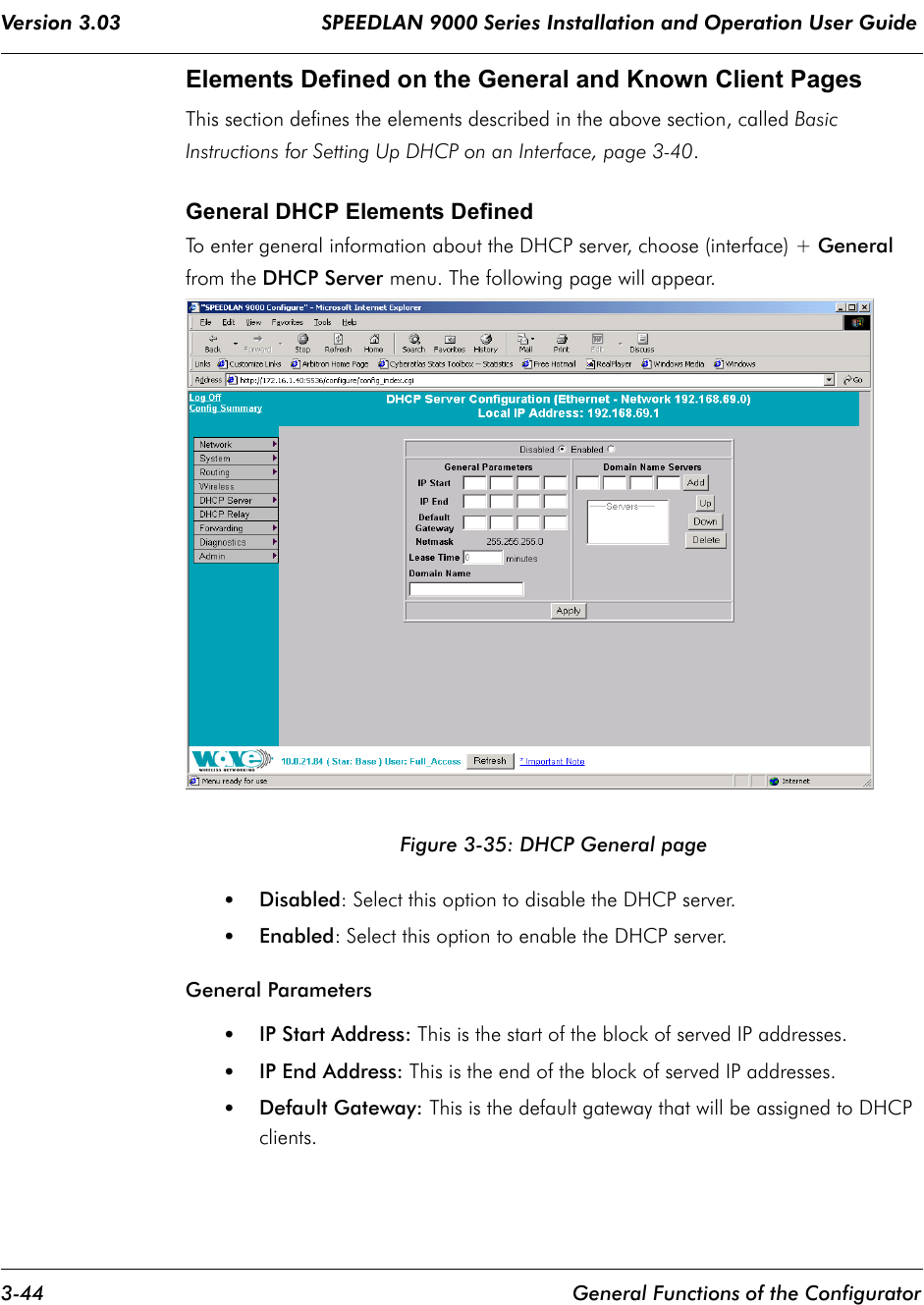
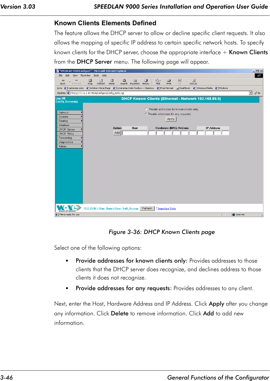
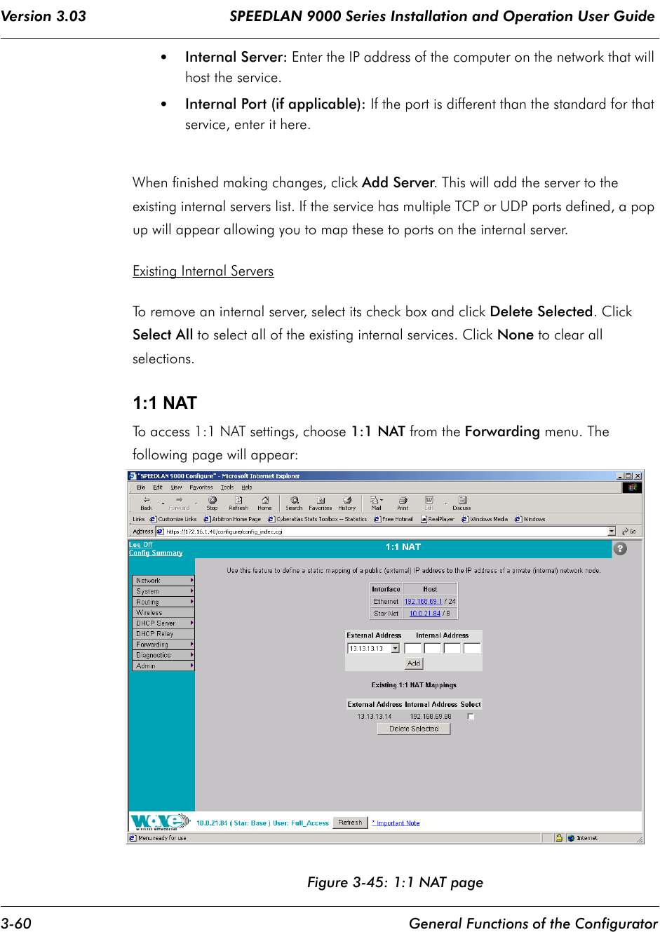
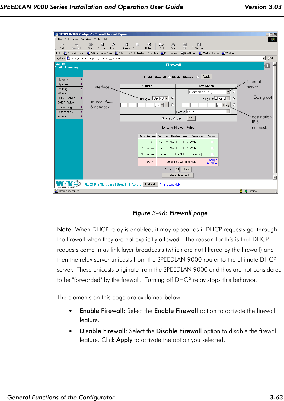
USERS MANUAL 1
Contents
1.
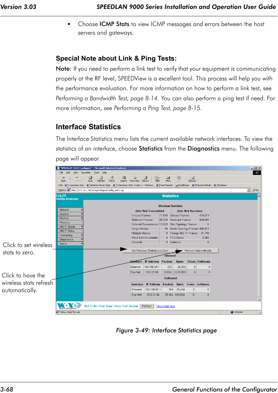
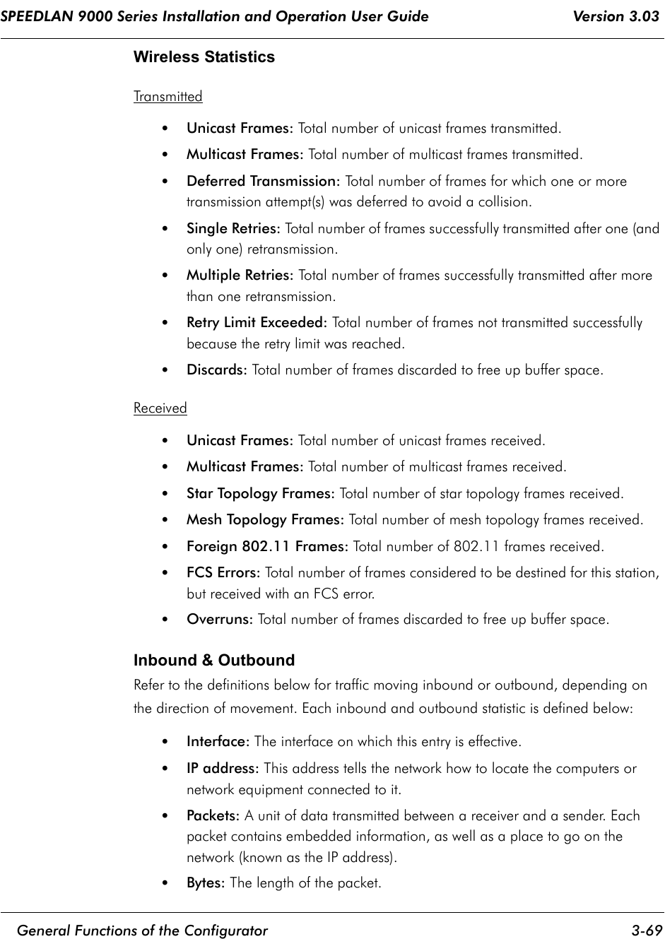
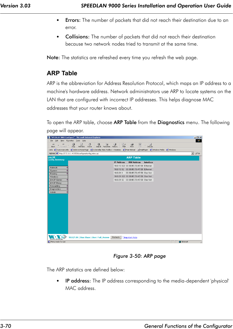
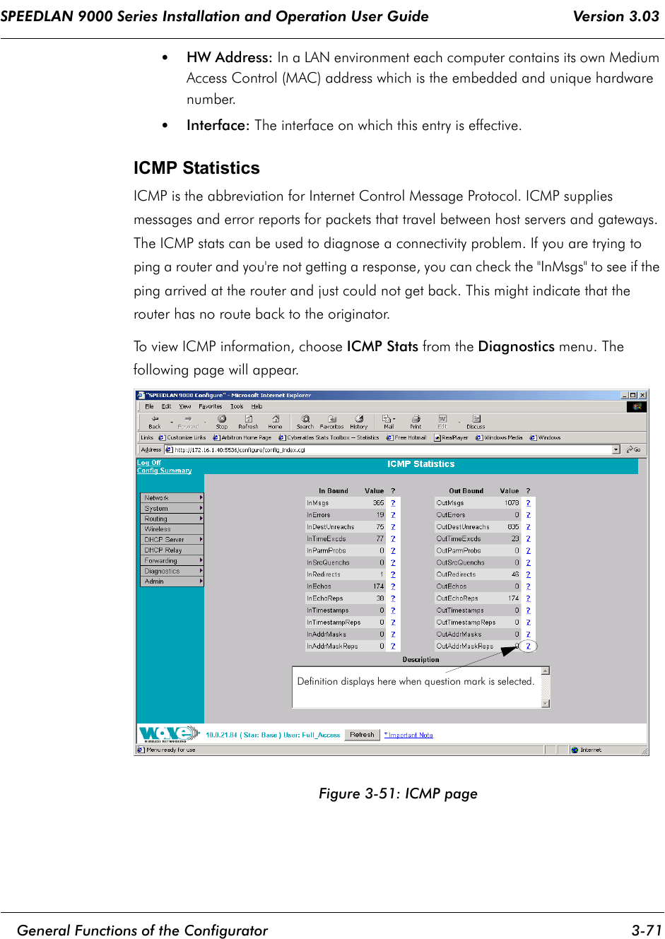
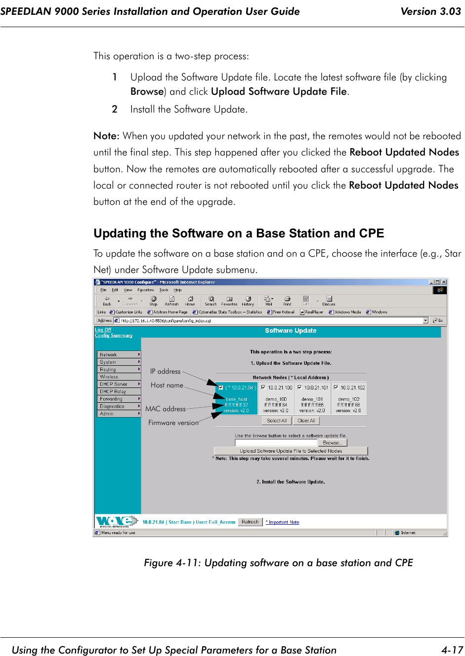
USERS MANUAL 1
2.
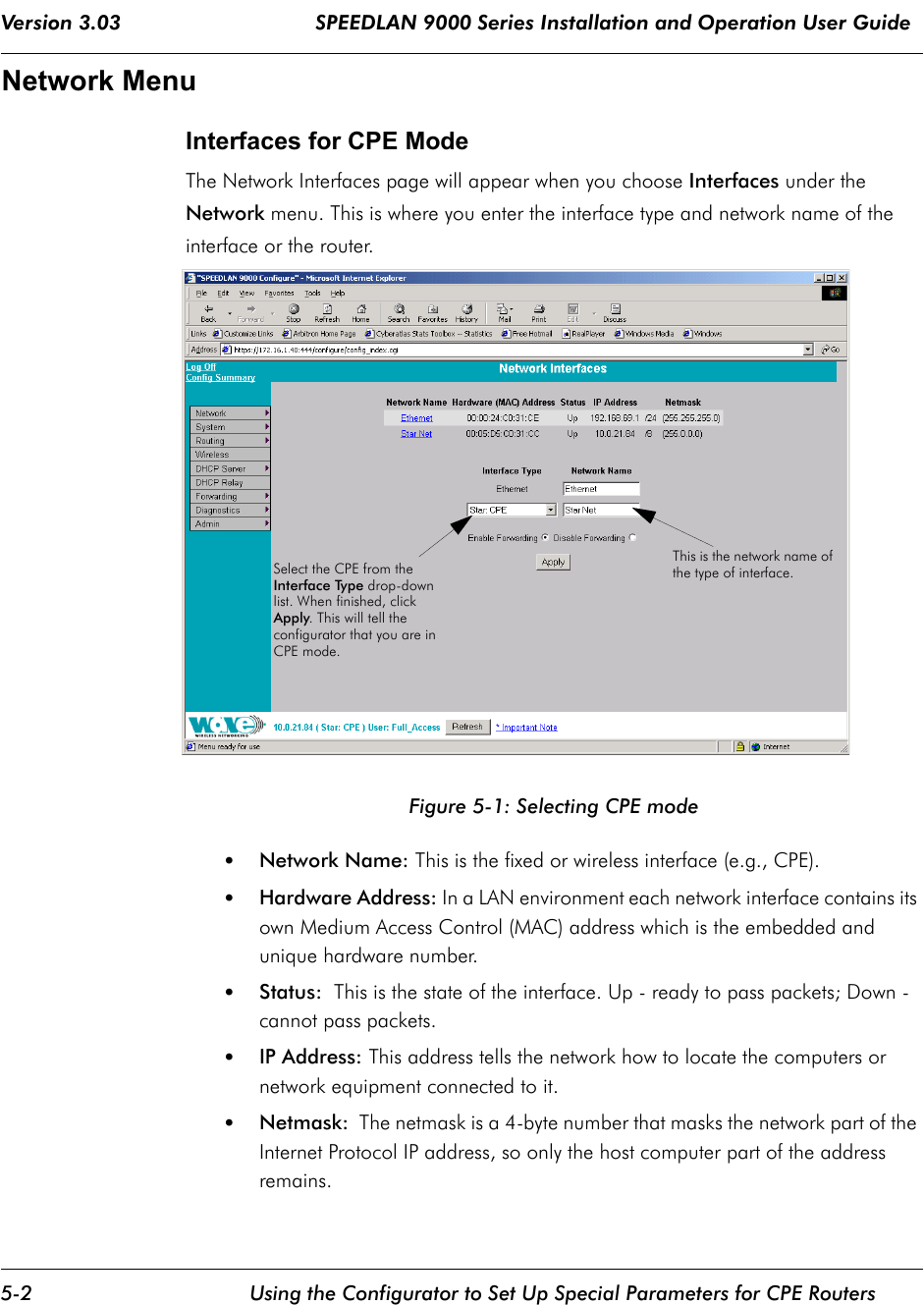
USERS MANUAL 2
3.
USERS MANUAL 3
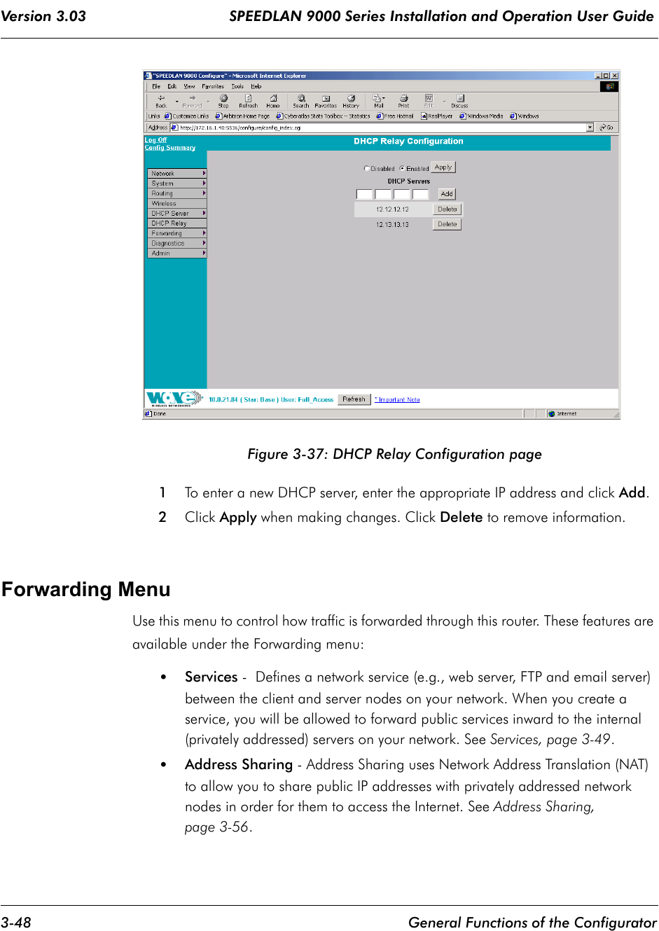
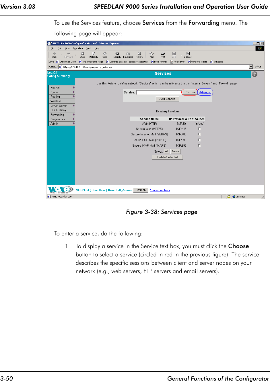
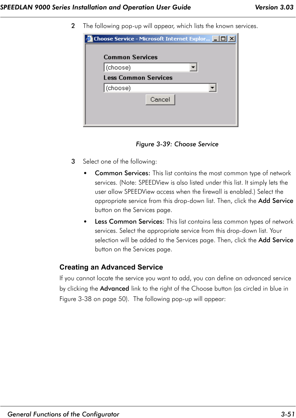
USERS MANUAL 1
Navigation menu
Upload a User Manual
Namespaces
Wiki Guide
HTML
PDF
Info
Views
User Manual
Discussion / Help
Navigation