Wave Wireless AIRLINKPROT1E1 User Manual ProT1E1 Manual
Wave Wireless Corporation ProT1E1 Manual
UserManual.wiki
>
Wave Wireless
>
AIRLINKPROT1E1 User Manual
ProT1E1 Manual
Navigation menu
Upload a User Manual
Namespaces
Wiki Guide
HTML
PDF
Info
Views
User Manual
Discussion / Help
Navigation
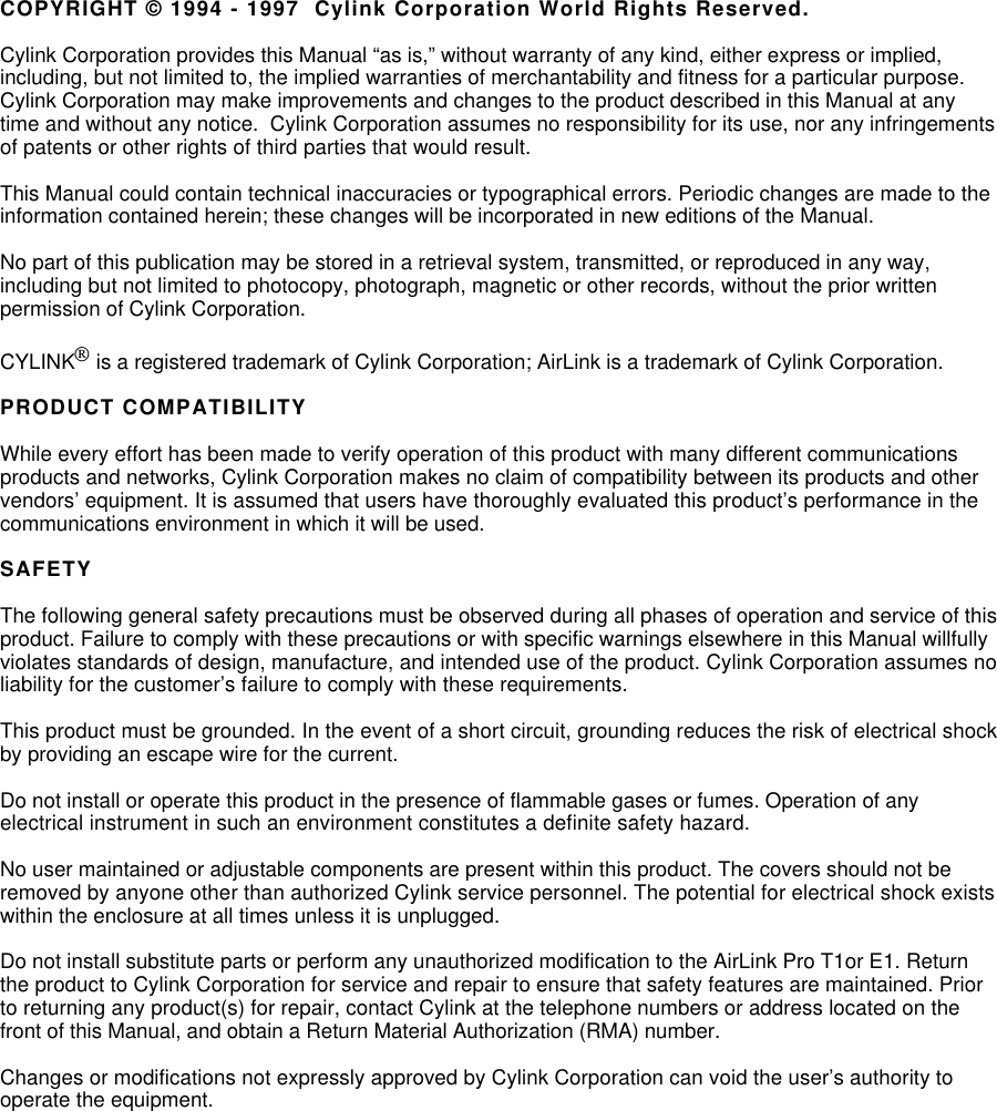
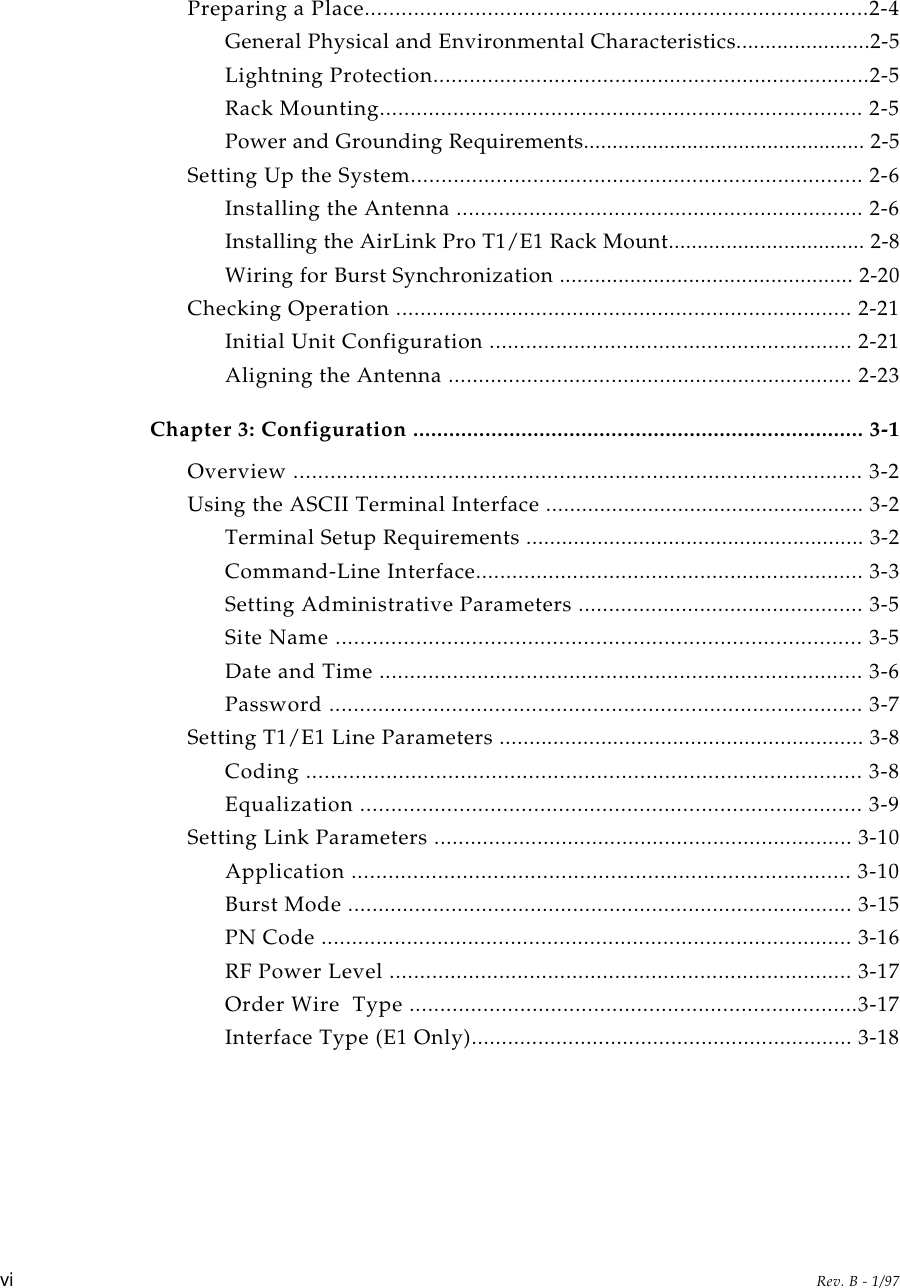
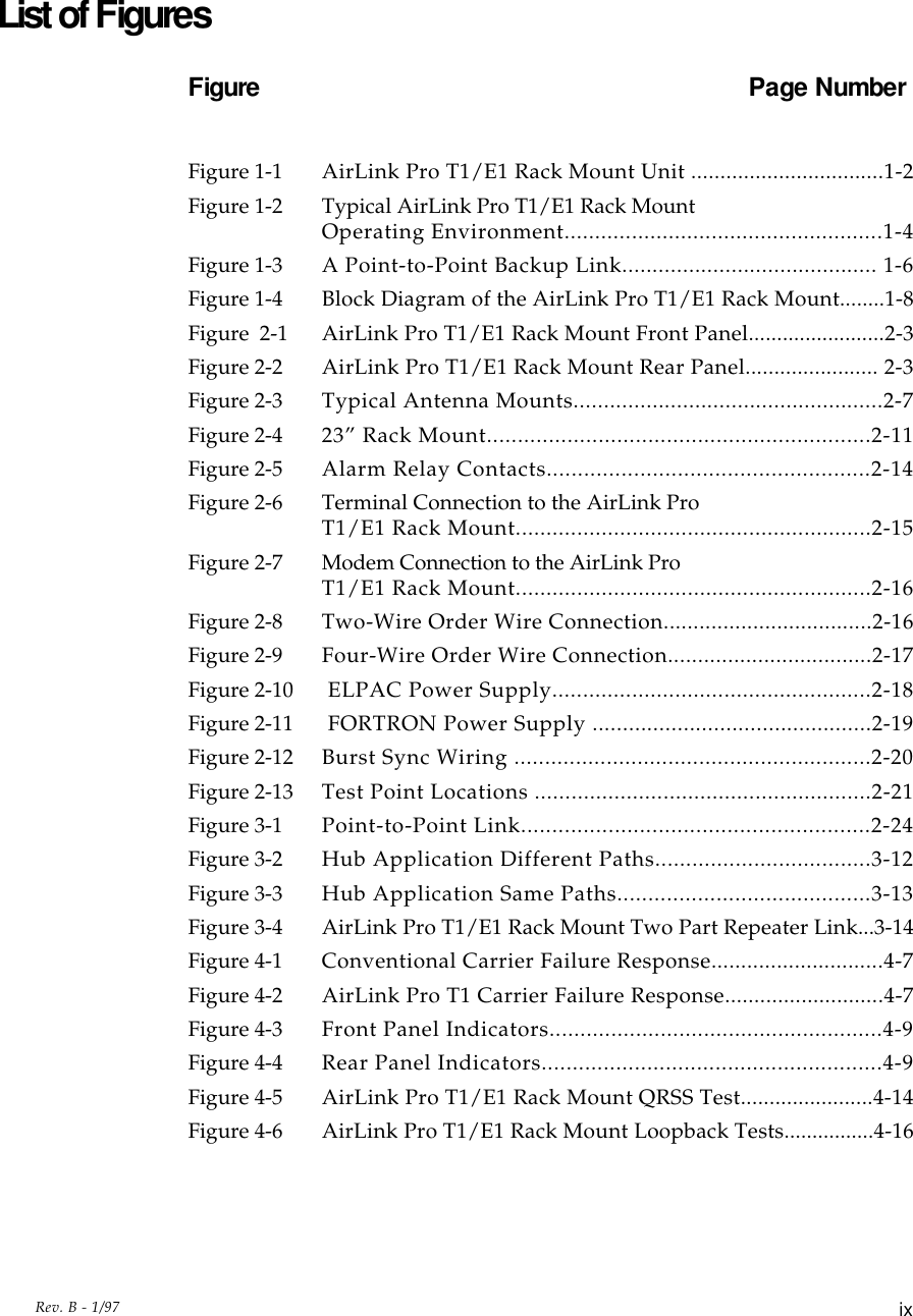

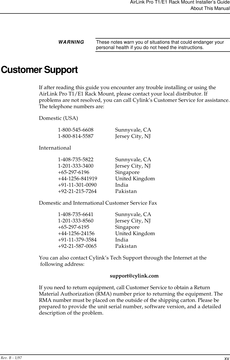

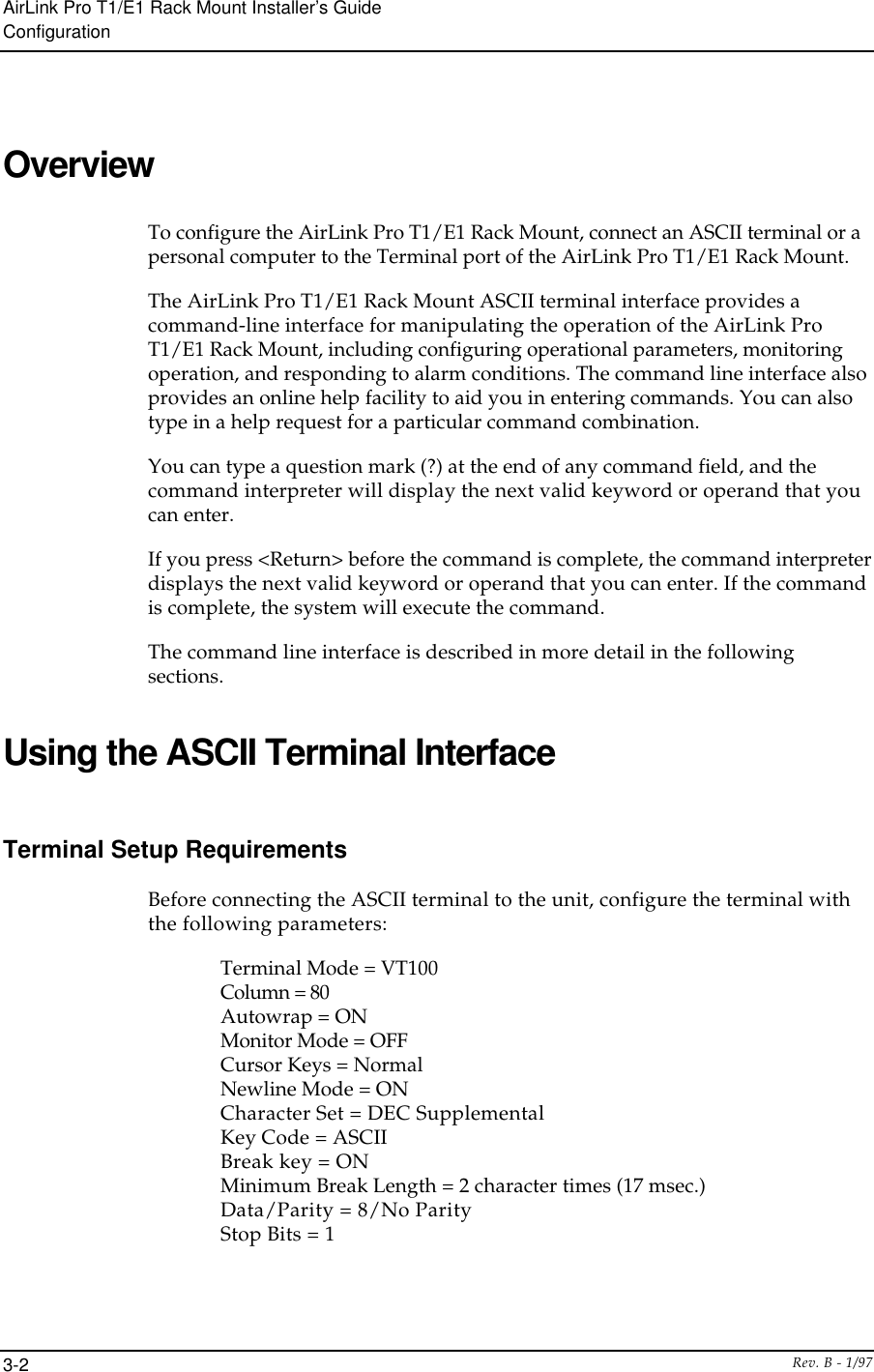
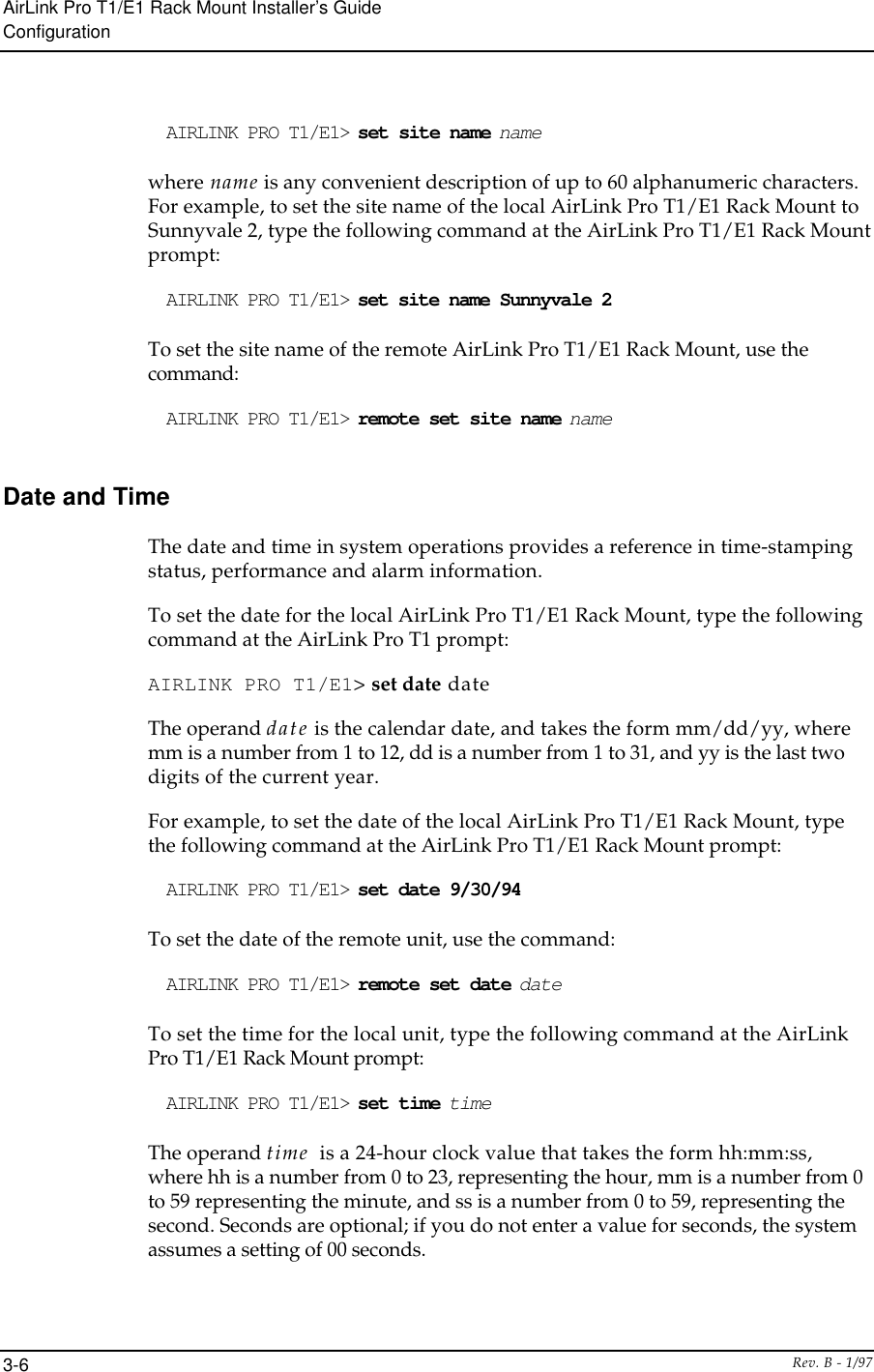
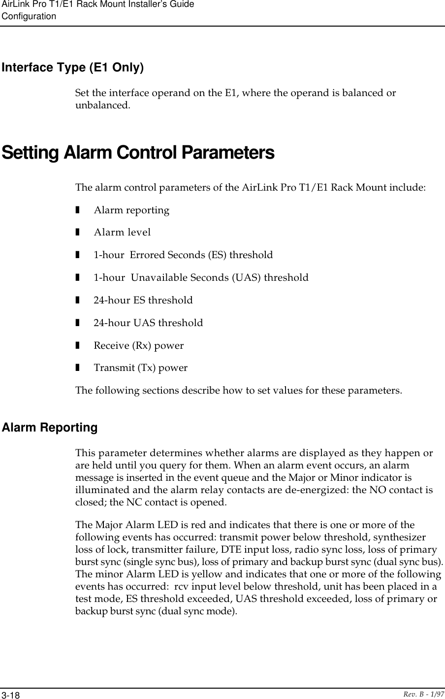
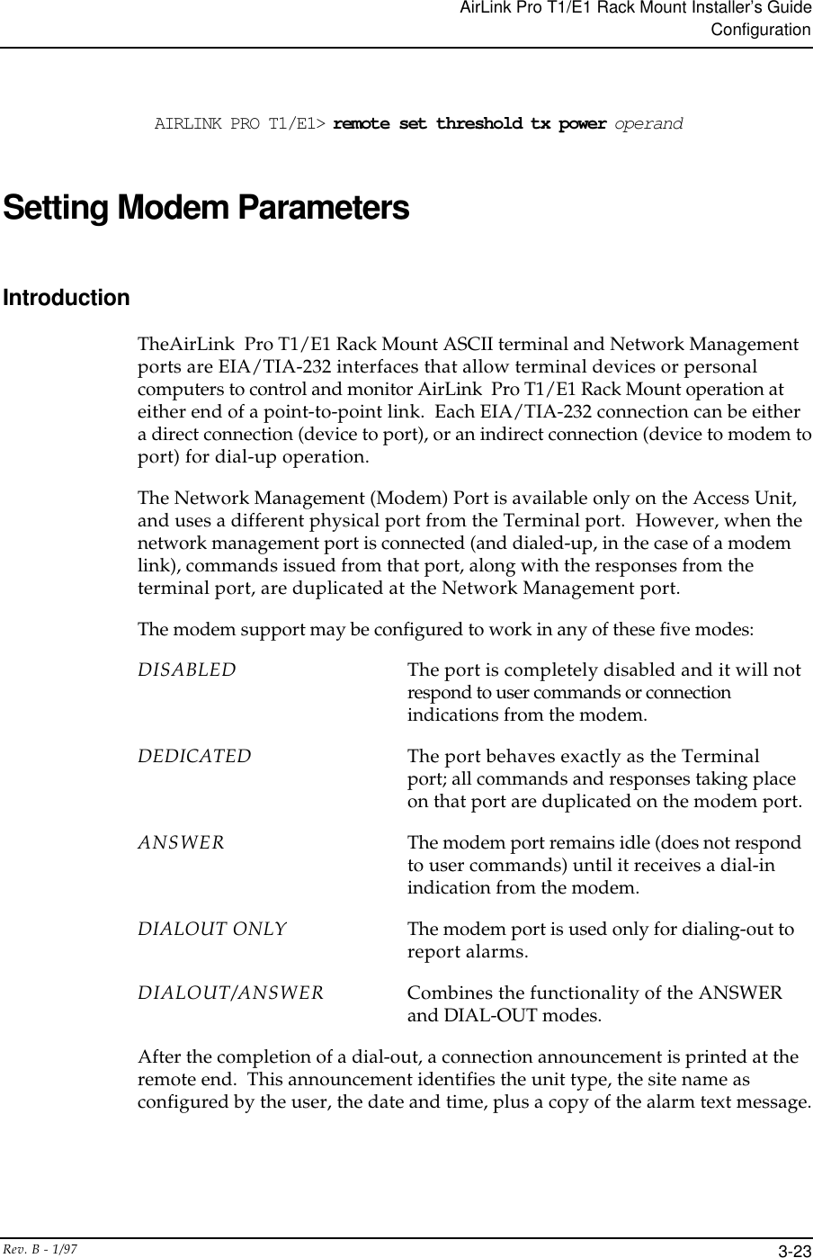
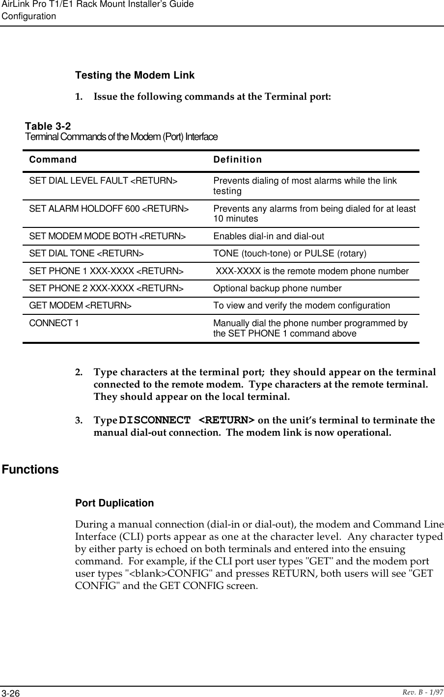
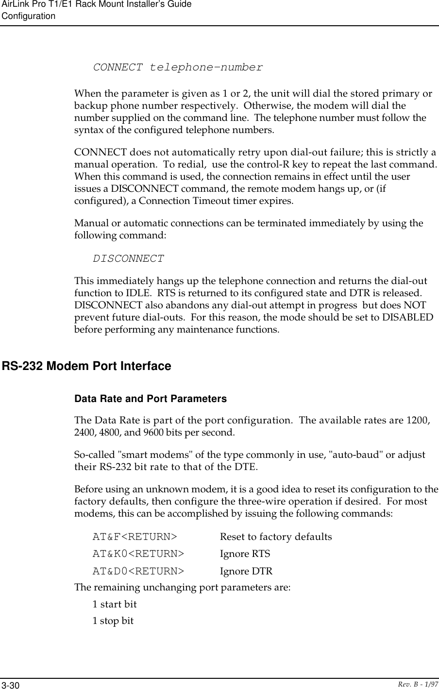
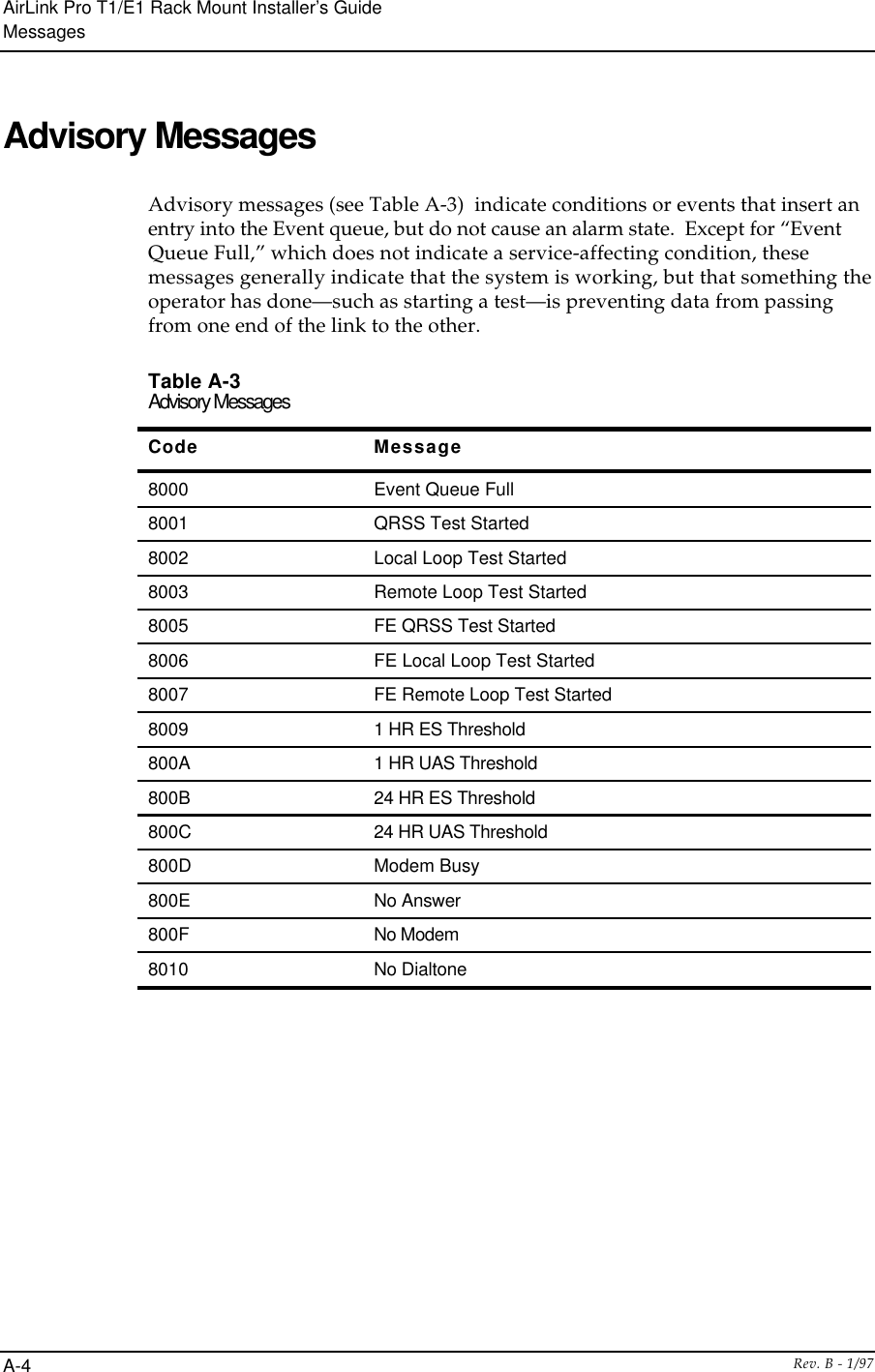
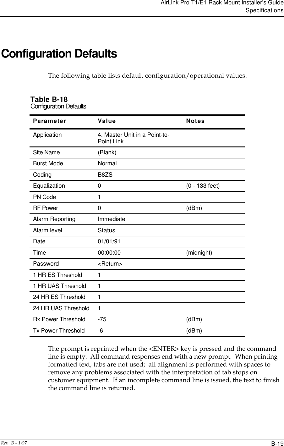
![AirLink Pro T1/E1 Rack Mount Installer’s GuideConfigurationRev. B - 1/973-32Table 3-3Modem Response DefinitionsModem Response Definition0 (zero) Numeric version of "OK"OK Successful execution of non-dial commandCONNECT [XXXX] carrier detected; XXXX = numeric bit rateRING Ringing detectedNO CARRIER No connection established, or connection lostERROR Error in command lineNO DIALTONE No dial tone presentBUSY Busy signalNO ANSWER 5 seconds of silence not detected if '@' dial modifier was used.](https://usermanual.wiki/Wave-Wireless/AIRLINKPROT1E1/User-Guide-28652-Page-81.png)
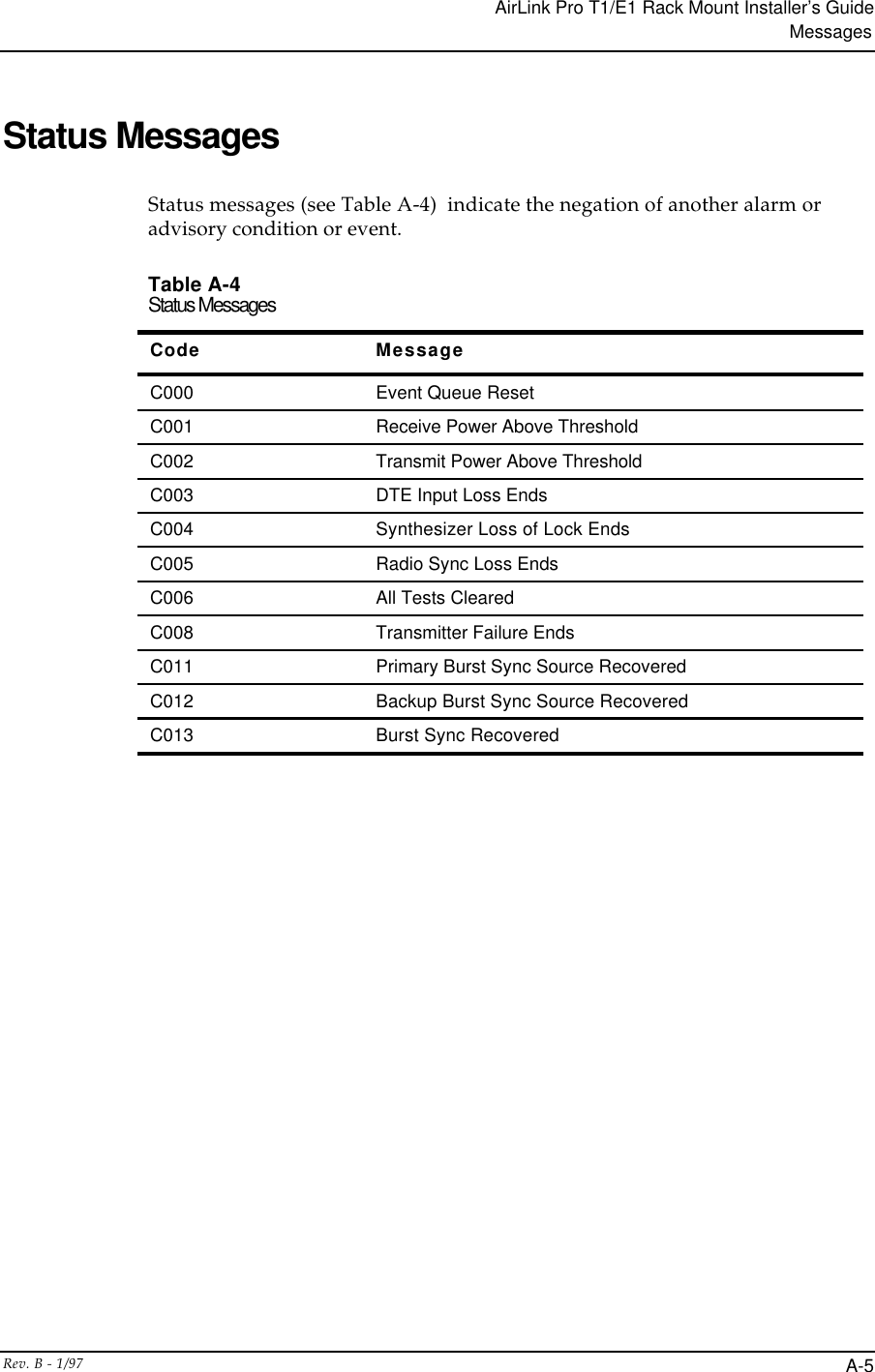
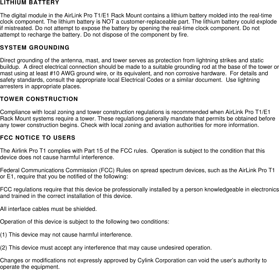
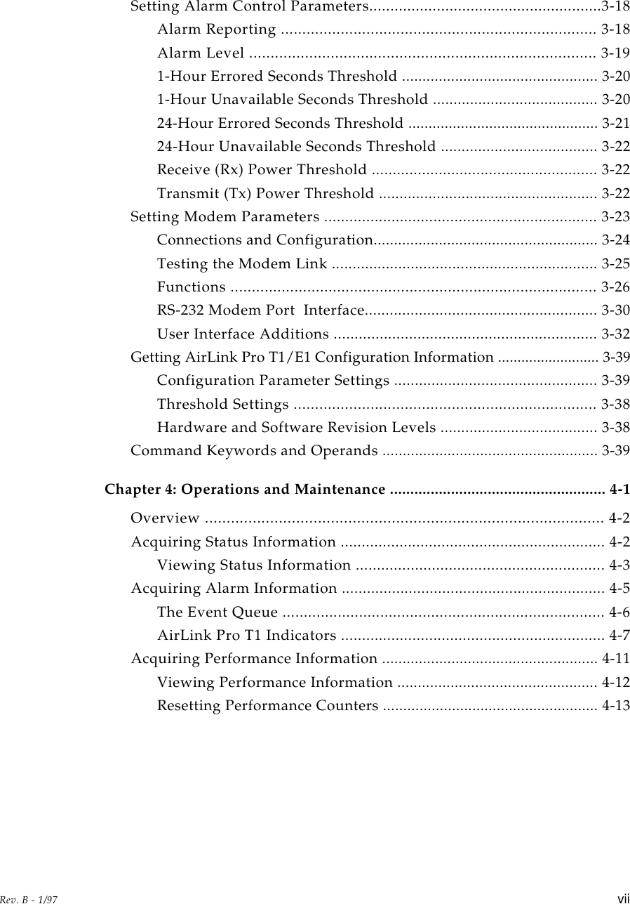
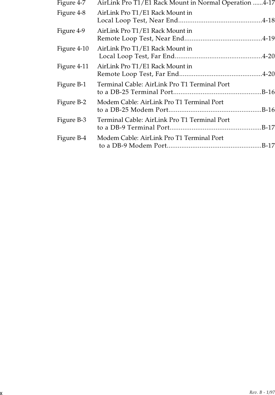
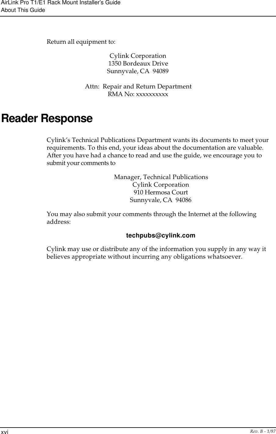
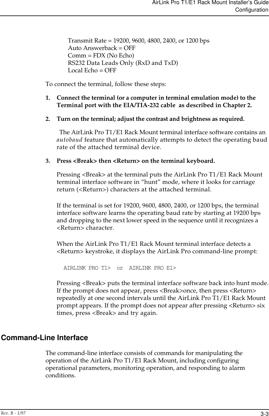
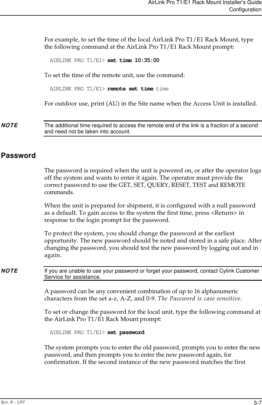
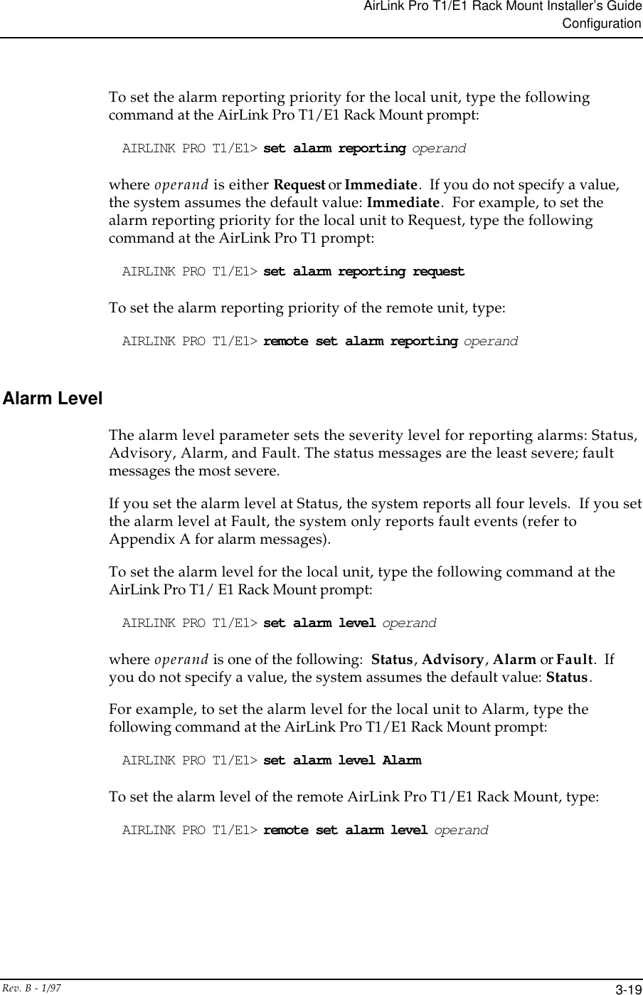
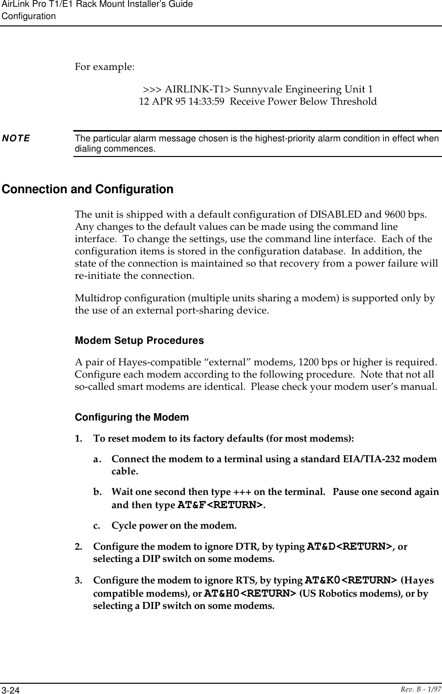
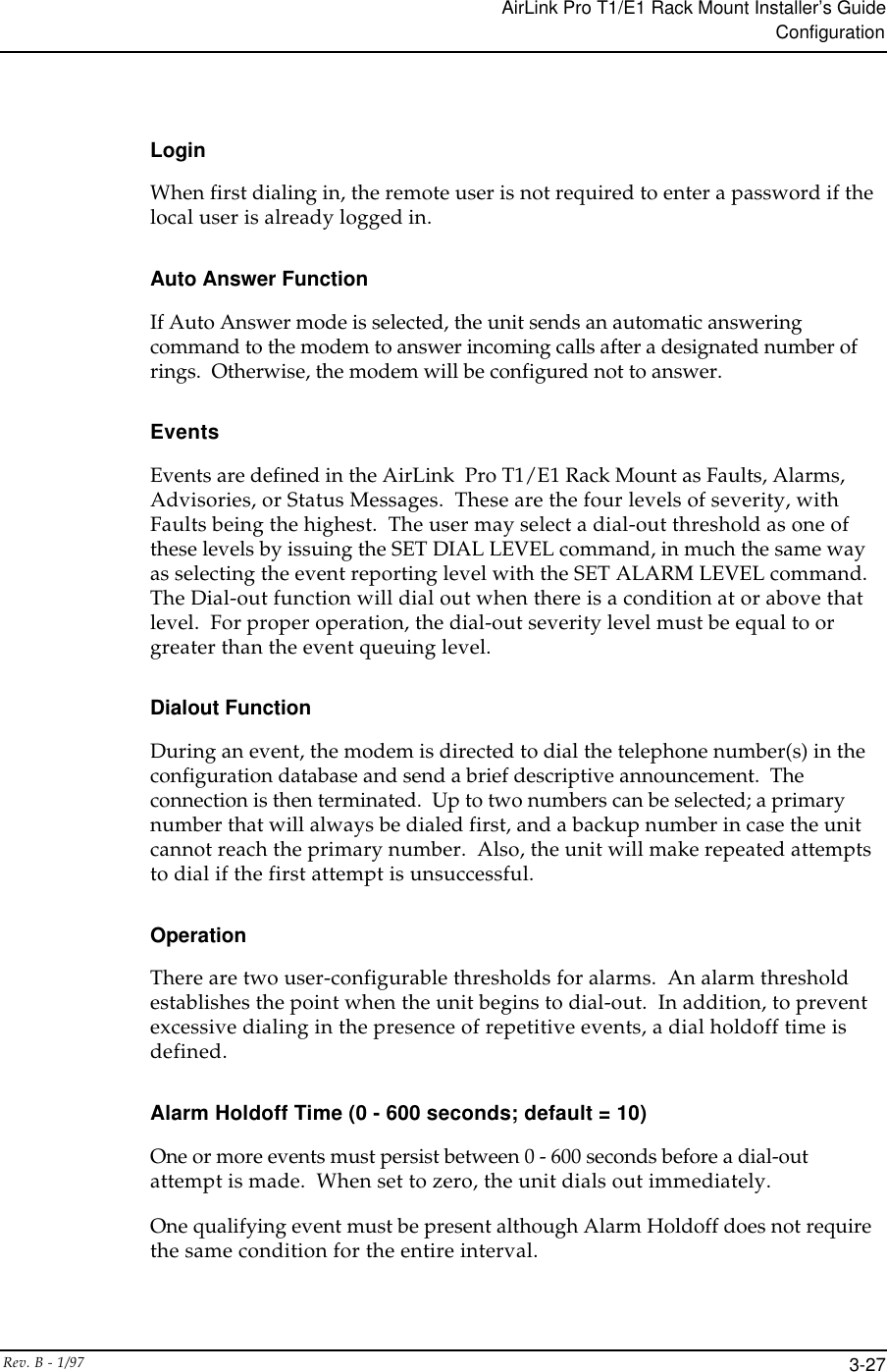
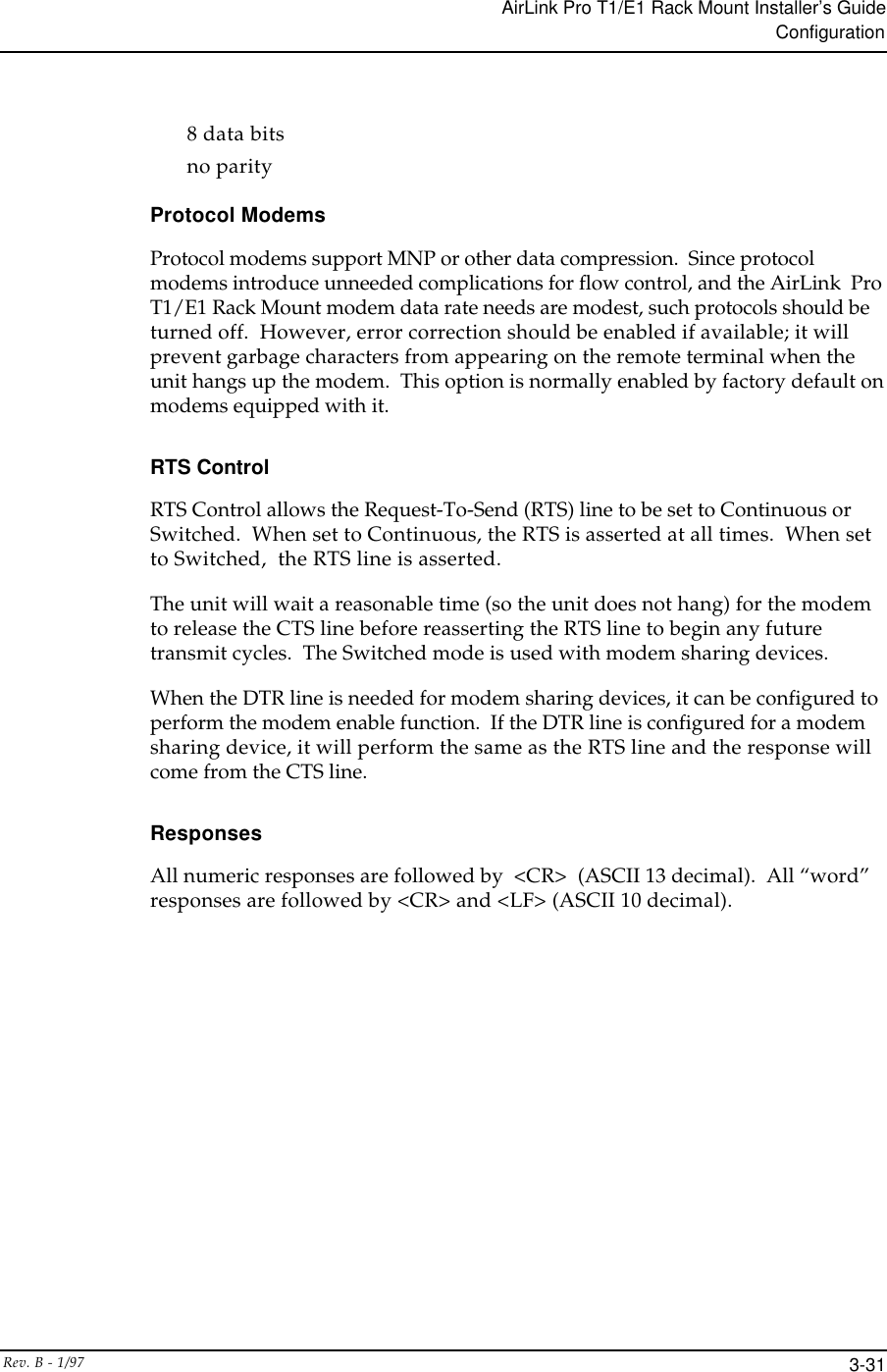
![AirLink Pro T1/E1 Rack Mount Installer’s GuideCommandsRev. B - 1/97 C-3ALARM REPORTING: {Request | immediate}ALARM LEVEL: {Status | Advisory | Alarm | Fault}DATE: MM/DD/YYTIME: HH:MM:SSPASSWORD: 16 character alphanumeric string. THRESHOLD 1 HR ES {1..999}1 HR UAS {1..99}24 HR ES {1..999}24 HR UAS {1..99}Rx Power {-35...-85}Tx Power {-3...20}Modem Dialout Setup CommandsCONNECT 1 PHONE #1CONNECT 2 PHONE #2DISCONNECTSET MODEMMODE {DISABLED | DEDICATED | DIAL_OUT |ANSWER | BOTH}RATE {1200 |2400 | 4800 |9600}RTS {SWITCHED | CONTINUOUS}DTR {SWITCHED | CONTINUOUS}CTS {OBEY | IGNORE}XOFF {OBEY | IGNORE}SET DIALTONEPULSEHOLDOFF {0...5000}LEVEL {FAULT | ALARM | ADVISORY | STATUS}RETRY {15...3600}SETALARM HOLDOFF {0...600]ANSWER TIMEOUT {0..99}CONNECTION TIMEOUT {0...43200}PHONE 1 (XXX) XXX-XXXXPHONE 2 (XXX) XXX-XXXX](https://usermanual.wiki/Wave-Wireless/AIRLINKPROT1E1/User-Guide-28652-Page-140.png)
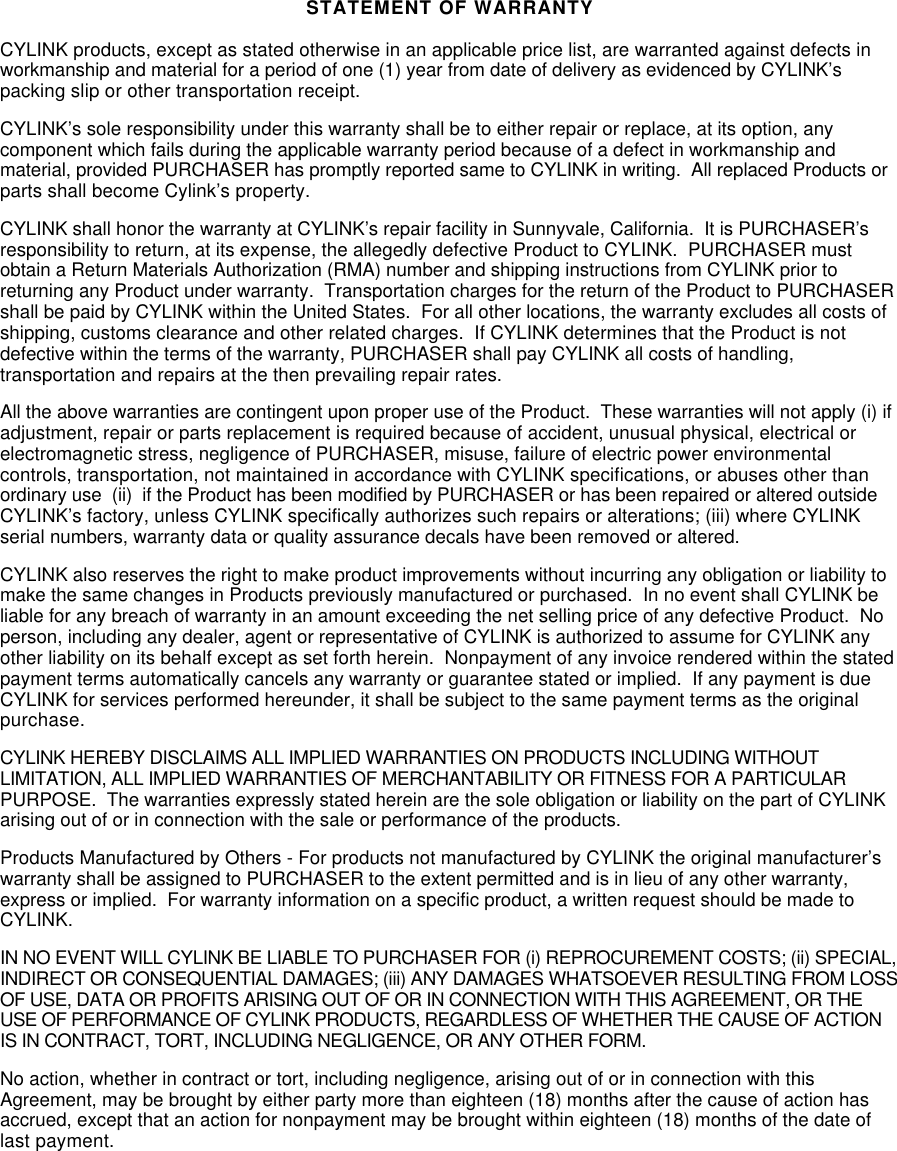
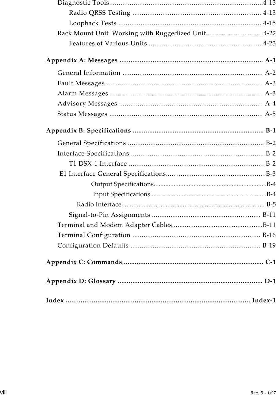
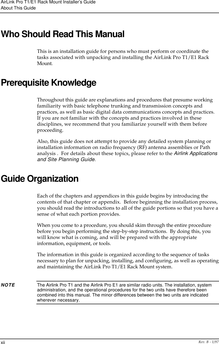
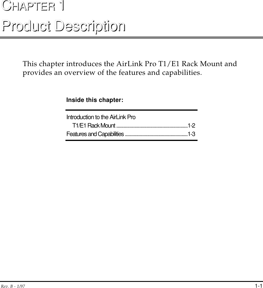
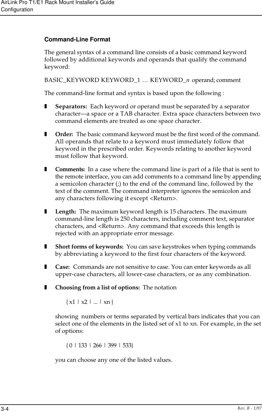
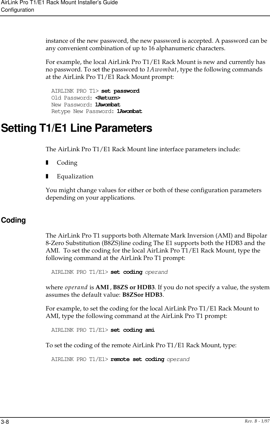
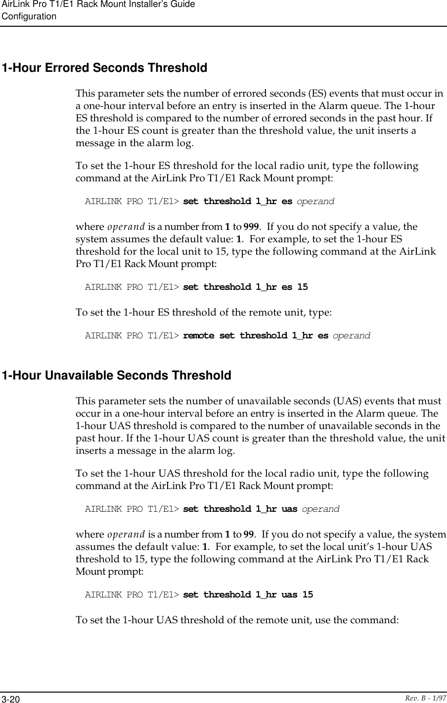
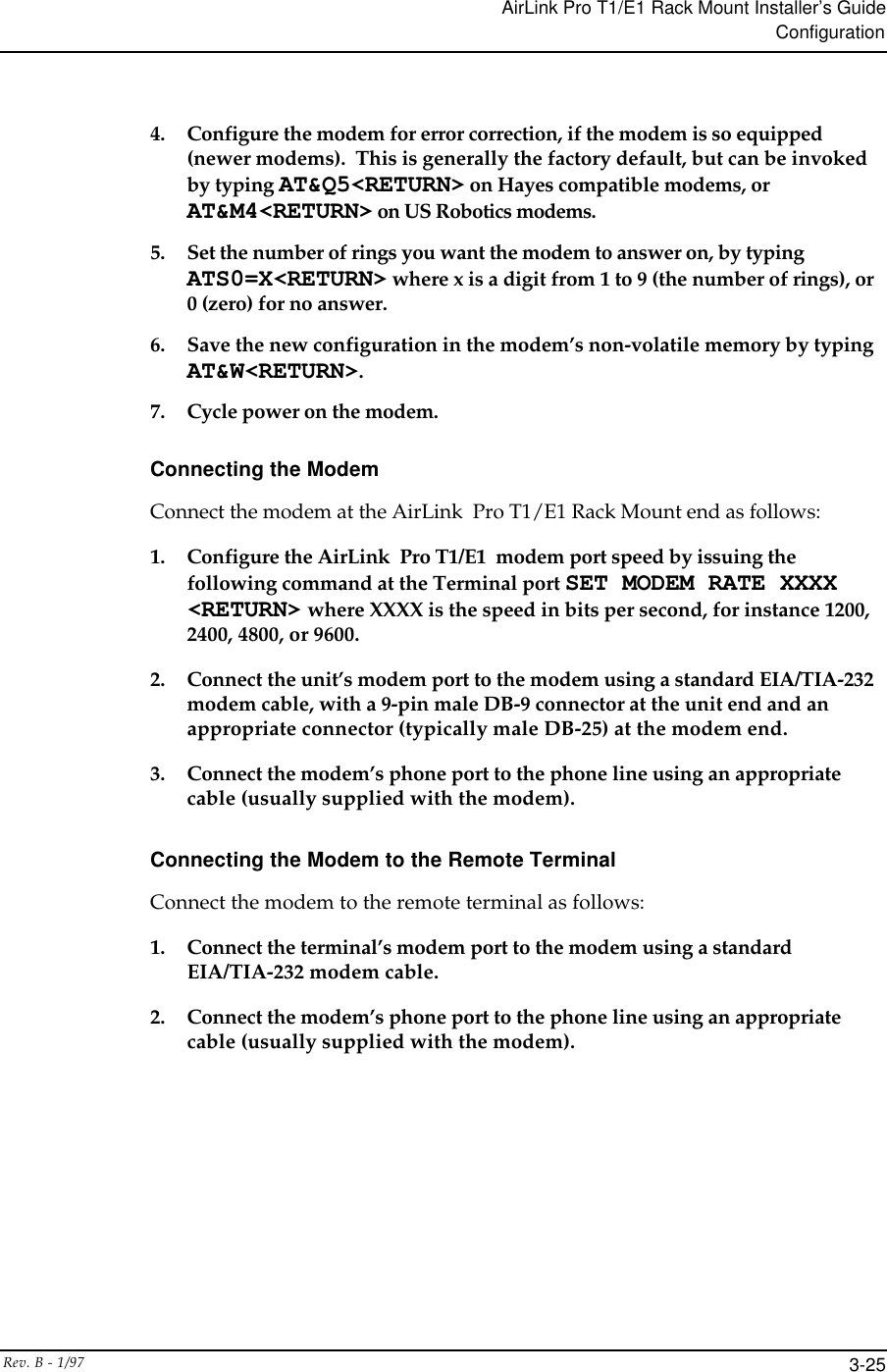
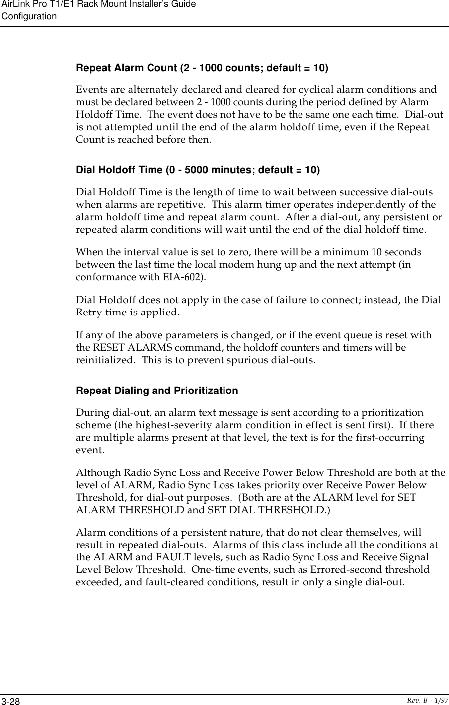
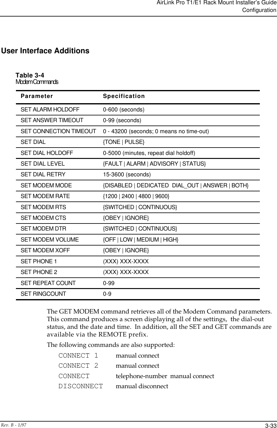
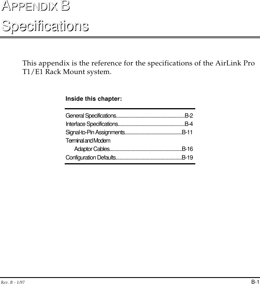
![AirLink Pro T1/E1 Rack Mount Installer’s GuideCommandsRev. B - 1/97 C-5Responses and AlertsEach of the following messages is an advisory. These advisories will nottrigger a dial-out, and they are entered into the Event Queue."Modem Busy""No Modem""No Answer""No Dialtone"All numeric responses are followed by <CR> (ASCII 13 decimal). All “word”responses are followed by <CR> and <LF> (ASCII 10 decimal).Modem Response DefinitionsModem Response Definition0 (zero) Numeric version of "OK"OK Successful execution of non-dial commandCONNECT [XXXX] carrier detected; XXXX = numeric bit rateRING Ringing detectedNO CARRIER No connection established, or connection lostERROR Error in command lineNO DIALTONE No dial tone presentBUSY Busy signalNO ANSWER 5 seconds of silence not detected if '@' dial modifier was used.Logging In and Logging OutThe operator must enter the LOGIN command keyword and provide the correctpassword to use the GET, SET, QUERY, RESET, TEST, and REMOTE commands.NOTE When the unit is prepared for shipment, it is configured with a null password as a default.To gain access to the system the first time, press <Return> in response to the loginprompt for the password. This password will remain in effect until changed.To login to the local AirLink Pro T1/E1 Rack Mount, type the followingcommand at the AirLink Pro T1/E1 Rack Mount prompt:](https://usermanual.wiki/Wave-Wireless/AIRLINKPROT1E1/User-Guide-28652-Page-142.png)