Wave Wireless AIRLINKPROT1E1 User Manual ProT1E1 Manual
Wave Wireless Corporation ProT1E1 Manual
ProT1E1 Manual

AirLink Pro
T1/E1 Rack Mount
Package: 82293-00B
Release Date: January, 1997
CYLINK CORPORATION
910 Hermosa Court
Sunnyvale, California 94086, USA
1-408-735-5800
CYLINK LIMITED U.K.
Tel: +44-1256-841919
Fax: +44-1256-24156
CYLINK CORPORATION (Singapore)
Tel: +65-2976-196
Fax: +65-2976-195
CYLINK CORPORATION (New Delhi)
Tel: +91-11-617-6913
Fax: +91-11-617-9529
CYLINK CORPORATION (Bejing)
Tel: +81-10-6467-1905
Fax: +86-10-6467-1906
CYLINK CORPORATION (Pakistan)
Tel: +92-21-5840743
Fax: +92-21-5840727
CYLINK CUSTOMER SUPPORT
1-800-545-6608 (USA - California)
1-800-814-5587 (USA - New Jersey)
1-408-735-5822 (International - California)
1-201-333-3400 (International - New Jersey)
+44-1256-58122 (Cylink Limited - U.K.)
Installer’s Guide
HOME
COPYRIGHT © 1994 - 1997 Cylink Corporation World Rights Reserved.
Cylink Corporation provides this Manual “as is,” without warranty of any kind, either express or implied,
including, but not limited to, the implied warranties of merchantability and fitness for a particular purpose.
Cylink Corporation may make improvements and changes to the product described in this Manual at any
time and without any notice. Cylink Corporation assumes no responsibility for its use, nor any infringements
of patents or other rights of third parties that would result.
This Manual could contain technical inaccuracies or typographical errors. Periodic changes are made to the
information contained herein; these changes will be incorporated in new editions of the Manual.
No part of this publication may be stored in a retrieval system, transmitted, or reproduced in any way,
including but not limited to photocopy, photograph, magnetic or other records, without the prior written
permission of Cylink Corporation.
CYLINK is a registered trademark of Cylink Corporation; AirLink is a trademark of Cylink Corporation.
PRODUCT COMPATIBILITY
While every effort has been made to verify operation of this product with many different communications
products and networks, Cylink Corporation makes no claim of compatibility between its products and other
vendors’ equipment. It is assumed that users have thoroughly evaluated this product’s performance in the
communications environment in which it will be used.
SAFETY
The following general safety precautions must be observed during all phases of operation and service of this
product. Failure to comply with these precautions or with specific warnings elsewhere in this Manual willfully
violates standards of design, manufacture, and intended use of the product. Cylink Corporation assumes no
liability for the customer’s failure to comply with these requirements.
This product must be grounded. In the event of a short circuit, grounding reduces the risk of electrical shock
by providing an escape wire for the current.
Do not install or operate this product in the presence of flammable gases or fumes. Operation of any
electrical instrument in such an environment constitutes a definite safety hazard.
No user maintained or adjustable components are present within this product. The covers should not be
removed by anyone other than authorized Cylink service personnel. The potential for electrical shock exists
within the enclosure at all times unless it is unplugged.
Do not install substitute parts or perform any unauthorized modification to the AirLink Pro T1or E1. Return
the product to Cylink Corporation for service and repair to ensure that safety features are maintained. Prior
to returning any product(s) for repair, contact Cylink at the telephone numbers or address located on the
front of this Manual, and obtain a Return Material Authorization (RMA) number.
Changes or modifications not expressly approved by Cylink Corporation can void the user’s authority to
operate the equipment.
LITHIUM BATTERY
The digital module in the AirLink Pro T1/E1 Rack Mount contains a lithium battery molded into the real-time
clock component. The lithium battery is NOT a customer-replaceable part. The lithium battery could explode
if mistreated. Do not attempt to expose the battery by opening the real-time clock component. Do not
attempt to recharge the battery. Do not dispose of the component by fire.
SYSTEM GROUNDING
Direct grounding of the antenna, mast, and tower serves as protection from lightning strikes and static
buildup. A direct electrical connection should be made to a suitable grounding rod at the base of the tower or
mast using at least #10 AWG ground wire, or its equivalent, and non corrosive hardware. For details and
safety standards, consult the appropriate local Electrical Codes or a similar document. Use lightning
arresters in appropriate places.
TOWER CONSTRUCTION
Compliance with local zoning and tower construction regulations is recommended when AirLink Pro T1/E1
Rack Mount systems require a tower. These regulations generally mandate that permits be obtained before
any tower construction begins. Check with local zoning and aviation authorities for more information.
FCC NOTICE TO USERS
The Airlink Pro T1 complies with Part 15 of the FCC rules. Operation is subject to the condition that this
device does not cause harmful interference.
Federal Communications Commission (FCC) Rules on spread spectrum devices, such as the AirLink Pro T1
or E1, require that you be notified of the following:
FCC regulations require that this device be professionally installed by a person knowledgeable in electronics
and trained in the correct installation of this device.
All interface cables must be shielded.
Operation of this device is subject to the following two conditions:
(1) This device may not cause harmful interference.
(2) This device must accept any interference that may cause undesired operation.
Changes or modifications not expressly approved by Cylink Corporation can void the user’s authority to
operate the equipment.
STATEMENT OF WARRANTY
CYLINK products, except as stated otherwise in an applicable price list, are warranted against defects in
workmanship and material for a period of one (1) year from date of delivery as evidenced by CYLINK’s
packing slip or other transportation receipt.
CYLINK’s sole responsibility under this warranty shall be to either repair or replace, at its option, any
component which fails during the applicable warranty period because of a defect in workmanship and
material, provided PURCHASER has promptly reported same to CYLINK in writing. All replaced Products or
parts shall become Cylink’s property.
CYLINK shall honor the warranty at CYLINK’s repair facility in Sunnyvale, California. It is PURCHASER’s
responsibility to return, at its expense, the allegedly defective Product to CYLINK. PURCHASER must
obtain a Return Materials Authorization (RMA) number and shipping instructions from CYLINK prior to
returning any Product under warranty. Transportation charges for the return of the Product to PURCHASER
shall be paid by CYLINK within the United States. For all other locations, the warranty excludes all costs of
shipping, customs clearance and other related charges. If CYLINK determines that the Product is not
defective within the terms of the warranty, PURCHASER shall pay CYLINK all costs of handling,
transportation and repairs at the then prevailing repair rates.
All the above warranties are contingent upon proper use of the Product. These warranties will not apply (i) if
adjustment, repair or parts replacement is required because of accident, unusual physical, electrical or
electromagnetic stress, negligence of PURCHASER, misuse, failure of electric power environmental
controls, transportation, not maintained in accordance with CYLINK specifications, or abuses other than
ordinary use (ii) if the Product has been modified by PURCHASER or has been repaired or altered outside
CYLINK’s factory, unless CYLINK specifically authorizes such repairs or alterations; (iii) where CYLINK
serial numbers, warranty data or quality assurance decals have been removed or altered.
CYLINK also reserves the right to make product improvements without incurring any obligation or liability to
make the same changes in Products previously manufactured or purchased. In no event shall CYLINK be
liable for any breach of warranty in an amount exceeding the net selling price of any defective Product. No
person, including any dealer, agent or representative of CYLINK is authorized to assume for CYLINK any
other liability on its behalf except as set forth herein. Nonpayment of any invoice rendered within the stated
payment terms automatically cancels any warranty or guarantee stated or implied. If any payment is due
CYLINK for services performed hereunder, it shall be subject to the same payment terms as the original
purchase.
CYLINK HEREBY DISCLAIMS ALL IMPLIED WARRANTIES ON PRODUCTS INCLUDING WITHOUT
LIMITATION, ALL IMPLIED WARRANTIES OF MERCHANTABILITY OR FITNESS FOR A PARTICULAR
PURPOSE. The warranties expressly stated herein are the sole obligation or liability on the part of CYLINK
arising out of or in connection with the sale or performance of the products.
Products Manufactured by Others - For products not manufactured by CYLINK the original manufacturer’s
warranty shall be assigned to PURCHASER to the extent permitted and is in lieu of any other warranty,
express or implied. For warranty information on a specific product, a written request should be made to
CYLINK.
IN NO EVENT WILL CYLINK BE LIABLE TO PURCHASER FOR (i) REPROCUREMENT COSTS; (ii) SPECIAL,
INDIRECT OR CONSEQUENTIAL DAMAGES; (iii) ANY DAMAGES WHATSOEVER RESULTING FROM LOSS
OF USE, DATA OR PROFITS ARISING OUT OF OR IN CONNECTION WITH THIS AGREEMENT, OR THE
USE OF PERFORMANCE OF CYLINK PRODUCTS, REGARDLESS OF WHETHER THE CAUSE OF ACTION
IS IN CONTRACT, TORT, INCLUDING NEGLIGENCE, OR ANY OTHER FORM.
No action, whether in contract or tort, including negligence, arising out of or in connection with this
Agreement, may be brought by either party more than eighteen (18) months after the cause of action has
accrued, except that an action for nonpayment may be brought within eighteen (18) months of the date of
last payment.
Rev. B - 1/97 v
Table of Contents
Preface .........................................................................................................ix
Who Should Read This Guide................................................................. x
Prerequisite Knowledge .......................................................................... x
Guide Organization ................................................................................ x
Guide Conventions ................................................................................. xi
Typographic Conventions ............................................................... xii
Keyboard Usage..............................................................................xii
Notes, Cautions, and Warnings ....................................................... xii
Customer Support ............................................................................... xiii
Reader Response .................................................................................. xiv
Chapter 1: Product Description................................................................... 1-1
Introduction to the AirLink Pro T1/E1 ................................................... 1-2
Features and Capabilities ................................................................... 1-3
Airlink Pro T1/E1 Antenna..............................................................1-5
ASCII terminal interface.................................................................1-5
Programmed Configuration Parameters .......................................... 1-5
Monitoring and Diagnostic Capabilities ......................................... 1-5
T1/E1 Link Backup Capability ...................................................... 1-6
Alarm Relay Contacts ................................................................... 1-7
Order Wire Interface ..................................................................... 1-7
Fail-Safe Link .............................................................................. 1-7
Block Diagram .............................................................................. 1-7
Chapter 2: Installation and System Administration.................................... 2-1
Overview............................................................................................ 2-2
Unpacking ........................................................................................... 2-2
Remote Connection................................................................................2-3
Identifying Physical Features.............................................................. 2-3
Front Panel.................................................................................... 2-3
Rear Panel..................................................................................... 2-3
vi Rev. B - 1/97
Preparing a Place..................................................................................2-4
General Physical and Environmental Characteristics.......................2-5
Lightning Protection........................................................................2-5
Rack Mounting............................................................................... 2-5
Power and Grounding Requirements................................................. 2-5
Setting Up the System.......................................................................... 2-6
Installing the Antenna ................................................................... 2-6
Installing the AirLink Pro T1/E1 Rack Mount.................................. 2-8
Wiring for Burst Synchronization .................................................. 2-20
Checking Operation ........................................................................... 2-21
Initial Unit Configuration ............................................................ 2-21
Aligning the Antenna ................................................................... 2-23
Chapter 3: Configuration ........................................................................... 3-1
Overview ............................................................................................ 3-2
Using the ASCII Terminal Interface ..................................................... 3-2
Terminal Setup Requirements ......................................................... 3-2
Command-Line Interface................................................................ 3-3
Setting Administrative Parameters ............................................... 3-5
Site Name ..................................................................................... 3-5
Date and Time ............................................................................... 3-6
Password ....................................................................................... 3-7
Setting T1/E1 Line Parameters ............................................................. 3-8
Coding .......................................................................................... 3-8
Equalization ................................................................................. 3-9
Setting Link Parameters ..................................................................... 3-10
Application ................................................................................. 3-10
Burst Mode ................................................................................... 3-15
PN Code ....................................................................................... 3-16
RF Power Level ............................................................................ 3-17
Order Wire Type .........................................................................3-17
Interface Type (E1 Only)............................................................... 3-18
Rev. B - 1/97 vii
Setting Alarm Control Parameters.......................................................3-18
Alarm Reporting .......................................................................... 3-18
Alarm Level ................................................................................. 3-19
1-Hour Errored Seconds Threshold ................................................ 3-20
1-Hour Unavailable Seconds Threshold ........................................ 3-20
24-Hour Errored Seconds Threshold ............................................... 3-21
24-Hour Unavailable Seconds Threshold ...................................... 3-22
Receive (Rx) Power Threshold ...................................................... 3-22
Transmit (Tx) Power Threshold ..................................................... 3-22
Setting Modem Parameters ................................................................. 3-23
Connections and Configuration....................................................... 3-24
Testing the Modem Link ................................................................ 3-25
Functions ...................................................................................... 3-26
RS-232 Modem Port Interface........................................................ 3-30
User Interface Additions ............................................................... 3-32
Getting AirLink Pro T1/E1 Configuration Information .......................... 3-39
Configuration Parameter Settings ................................................. 3-39
Threshold Settings ....................................................................... 3-38
Hardware and Software Revision Levels ...................................... 3-38
Command Keywords and Operands ..................................................... 3-39
Chapter 4: Operations and Maintenance ..................................................... 4-1
Overview ............................................................................................ 4-2
Acquiring Status Information ............................................................... 4-2
Viewing Status Information ........................................................... 4-3
Acquiring Alarm Information ............................................................... 4-5
The Event Queue ............................................................................ 4-6
AirLink Pro T1 Indicators ............................................................... 4-7
Acquiring Performance Information ..................................................... 4-11
Viewing Performance Information ................................................. 4-12
Resetting Performance Counters ..................................................... 4-13
viii Rev. B - 1/97
Diagnostic Tools..................................................................................4-13
Radio QRSS Testing ..................................................................... 4-13
Loopback Tests ............................................................................. 4-15
Rack Mount Unit Working with Ruggedized Unit ................................4-22
Features of Various Units ..............................................................4-23
Appendix A: Messages .............................................................................. A-1
General Information ........................................................................... A-2
Fault Messages ................................................................................... A-3
Alarm Messages ................................................................................. A-3
Advisory Messages ............................................................................. A-4
Status Messages .................................................................................. A-5
Appendix B: Specifications ........................................................................ B-1
General Specifications ......................................................................... B-2
Interface Specifications ....................................................................... B-2
T1 DSX-1 Interface ........................................................................ B-2
E1 Interface General Specifications......................................................B-3
Output Specifications....................................................................B-4
Input Specifications......................................................................B-4
Radio Interface ................................................................................... B-5
Signal-to-Pin Assignments ........................................................... B-11
Terminal and Modem Adapter Cables..................................................B-11
Terminal Configuration ..................................................................... B-16
Configuration Defaults ...................................................................... B-19
Appendix C: Commands ............................................................................. C-1
Appendix D: Glossary ............................................................................... D-1
Index ................................................................................................... Index-1
Rev. B - 1/97 ix
List of Figures
Figure Page Number
Figure 1-1 AirLink Pro T1/E1 Rack Mount Unit .................................1-2
Figure 1-2 Typical AirLink Pro T1/E1 Rack Mount
Operating Environment....................................................1-4
Figure 1-3 A Point-to-Point Backup Link.......................................... 1-6
Figure 1-4 Block Diagram of the AirLink Pro T1/E1 Rack Mount........1-8
Figure 2-1 AirLink Pro T1/E1 Rack Mount Front Panel........................2-3
Figure 2-2 AirLink Pro T1/E1 Rack Mount Rear Panel....................... 2-3
Figure 2-3 Typical Antenna Mounts...................................................2-7
Figure 2-4 23” Rack Mount..............................................................2-11
Figure 2-5 Alarm Relay Contacts....................................................2-14
Figure 2-6 Terminal Connection to the AirLink Pro
T1/E1 Rack Mount..........................................................2-15
Figure 2-7 Modem Connection to the AirLink Pro
T1/E1 Rack Mount..........................................................2-16
Figure 2-8 Two-Wire Order Wire Connection...................................2-16
Figure 2-9 Four-Wire Order Wire Connection..................................2-17
Figure 2-10 ELPAC Power Supply....................................................2-18
Figure 2-11 FORTRON Power Supply ..............................................2-19
Figure 2-12 Burst Sync Wiring ..........................................................2-20
Figure 2-13 Test Point Locations .......................................................2-21
Figure 3-1 Point-to-Point Link........................................................2-24
Figure 3-2 Hub Application Different Paths...................................3-12
Figure 3-3 Hub Application Same Paths.........................................3-13
Figure 3-4 AirLink Pro T1/E1 Rack Mount Two Part Repeater Link...3-14
Figure 4-1 Conventional Carrier Failure Response.............................4-7
Figure 4-2 AirLink Pro T1 Carrier Failure Response...........................4-7
Figure 4-3 Front Panel Indicators......................................................4-9
Figure 4-4 Rear Panel Indicators.......................................................4-9
Figure 4-5 AirLink Pro T1/E1 Rack Mount QRSS Test.......................4-14
Figure 4-6 AirLink Pro T1/E1 Rack Mount Loopback Tests................4-16
Rev. B - 1/97
x
Figure 4-7 AirLink Pro T1/E1 Rack Mount in Normal Operation ......4-17
Figure 4-8 AirLink Pro T1/E1 Rack Mount in
Local Loop Test, Near End..............................................4-18
Figure 4-9 AirLink Pro T1/E1 Rack Mount in
Remote Loop Test, Near End...........................................4-19
Figure 4-10 AirLink Pro T1/E1 Rack Mount in
Local Loop Test, Far End................................................4-20
Figure 4-11 AirLink Pro T1/E1 Rack Mount in
Remote Loop Test, Far End..............................................4-20
Figure B-1 Terminal Cable: AirLink Pro T1 Terminal Port
to a DB-25 Terminal Port................................................B-16
Figure B-2 Modem Cable: AirLink Pro T1 Terminal Port
to a DB-25 Modem Port...................................................B-16
Figure B-3 Terminal Cable: AirLink Pro T1 Terminal Port
to a DB-9 Terminal Port..................................................B-17
Figure B-4 Modem Cable: AirLink Pro T1 Terminal Port
to a DB-9 Modem Port....................................................B-17

Rev. B - 1/97 xi
P
PREFACE
REFACE
About This Guide
About This Guide
The AirLink Pro T1/E1 Rack Mount Installer’s Guide covers the
information needed to unpack, install, configure, and operate the
AirLink Pro T1 or the Airlink Pro E1 system. Begin by reading this
preface for more information about how this guide supports your use
of the AirLink Pro T1/E1 Rack Mount system.
Inside this chapter:
Who Should Read This Manual...............................................xiii
Prerequisite Knowledge .......................................................xiv
Guide Organization..................................................................xiv
Guide Conventions....................................................................xv
Customer Support ............................................................... xvii
Reader Response ................................................................. xviii

AirLink Pro T1/E1 Rack Mount Installer’s Guide
About This Guide
Rev. B - 1/97
xii
Who Should Read This Manual
This is an installation guide for persons who must perform or coordinate the
tasks associated with unpacking and installing the AirLink Pro T1/E1 Rack
Mount.
Prerequisite Knowledge
Throughout this guide are explanations and procedures that presume working
familiarity with basic telephone trunking and transmission concepts and
practices, as well as basic digital data communications concepts and practices.
If you are not familiar with the concepts and practices involved in these
disciplines, we recommend that you familiarize yourself with them before
proceeding.
Also, this guide does not attempt to provide any detailed system planning or
installation information on radio frequency (RF) antenna assemblies or Path
analysis . For details about these topics, please refer to the Airlink Applications
and Site Planning Guide.
Guide Organization
Each of the chapters and appendices in this guide begins by introducing the
contents of that chapter or appendix. Before beginning the installation process,
you should read the introductions to all of the guide portions so that you have a
sense of what each portion provides.
When you come to a procedure, you should skim through the entire procedure
before you begin performing the step-by-step instructions. By doing this, you
will know what is coming, and will be prepared with the appropriate
information, equipment, or tools.
The information in this guide is organized according to the sequence of tasks
necessary to plan for unpacking, installing, and configuring, as well as operating
and maintaining the AirLink Pro T1/E1 Rack Mount system.
NOTE The Airlink Pro T1 and the Airlink Pro E1 are similar radio units. The installation, system
administration, and the operational procedures for the two units have therefore been
combined into this manual. The minor differences between the two units are indicated
wherever necessary.

AirLink Pro T1/E1 Rack Mount Installer’s Guide
About This Manual
Rev. B - 1/97 xiii
The guide is divided into the following sections:
Guide Section Description
Chapter 1:
Product Description Describes the features and capabilities of the AirLink
Pro T1/E1 system.
Chapter 2:
Installation and
SystemAdministration
Outlines the procedures for unpacking and installing the
AirLink Pro T1/E1 Rack Mount system hardware,
connecting the antenna, and performing initial operation
checks.
Chapter 3:
Configuring the AirLink Pro
T1/E1 Rack Mount
Provides instructions for configuring the AirLink Pro
T1/E1.
Chapter 4:
Operations and Maintenance Contains information on the operation and maintenance
of the AirLink Pro T1/E1 system.
Appendix A:
Messages Lists the system alarm, status, and error messages.
Appendix B:
Specifications Contains a quick reference to the AirLink Pro T1/E1
Rack Mount system specifications.
Appendix C:
Commands Provides a list of frequently used commands.
Appendix D:
Glossary Provides definitions for the terms commonly used
throughout this guide.
Index Provides a quick reference to assist you in locating
important topics in the guide.
Guide Conventions
The procedures and instructions in this guide use the following conventions:
❚Typography that highlights information within text, including screen
displays, figures, and tables.
❚Keyboard usage conventions.
❚Notes that add information, point to other important considerations, or
alert you to possible risks to yourself, your equipment, or your data.

AirLink Pro T1/E1 Rack Mount Installer’s Guide
About This Guide
Rev. B - 1/97
xiv
Typographic Conventions
❚Terminal displays are shown as text in the Courier font:
AIRLINK PRO T1> get configuration
Site Name: Sunnyvale 2
Application: 6. Slave unit in a point-to-point Link
Burst Mode: Normal
Coding: B8ZS
Equalization: 0 - 133 ft
PN Code: 1
RF Power: 10 dBm
Alarm Reporting: Immediate
Alarm Level: Status
Date/Time: May 1 1996 10:35:00
❚Bold Courier font indicates a command keyword or operand that you
are expected to type exactly as shown.
❚Italic Courier font indicates a command operand that you must
replace with a selected value when you type the command.
❚Named keys in text are shown enclosed in angle brackets. The notation
<Return> is used to indicate either the Return key or the Enter key.
Keyboard Usage
❚All command examples shown in text are executed by typing the command
and then pressing <Return>.
❚Two or more keys that must be pressed simultaneously are shown in text
linked with a plus (+) sign: <Ctrl>+C.
Notes, Cautions, and Warnings
NOTE The standard text note highlights important or additional
information for you to consider.
CAUTION These notes warn you of situations that could result in damage
to your equipment or loss of data if you do not heed the
instructions.

AirLink Pro T1/E1 Rack Mount Installer’s Guide
About This Manual
Rev. B - 1/97 xv
WARNING These notes warn you of situations that could endanger your
personal health if you do not heed the instructions.
Customer Support
If after reading this guide you encounter any trouble installing or using the
AirLink Pro T1/E1 Rack Mount, please contact your local distributor. If
problems are not resolved, you can call Cylink’s Customer Service for assistance.
The telephone numbers are:
Domestic (USA)
1-800-545-6608 Sunnyvale, CA
1-800-814-5587 Jersey City, NJ
International
1-408-735-5822 Sunnyvale, CA
1-201-333-3400 Jersey City, NJ
+65-297-6196 Singapore
+44-1256-841919 United Kingdom
+91-11-301-0090 India
+92-21-215-7264 Pakistan
Domestic and International Customer Service Fax
1-408-735-6641 Sunnyvale, CA
1-201-333-8560 Jersey City, NJ
+65-297-6195 Singapore
+44-1256-24156 United Kingdom
+91-11-379-3584 India
+92-21-587-0065 Pakistan
You can also contact Cylink’s Tech Support through the Internet at the
following address:
support@cylink.com
If you need to return equipment, call Customer Service to obtain a Return
Material Authorization (RMA) number prior to returning the equipment. The
RMA number must be placed on the outside of the shipping carton. Please be
prepared to provide the unit serial number, software version, and a detailed
description of the problem.

AirLink Pro T1/E1 Rack Mount Installer’s Guide
About This Guide
Rev. B - 1/97
xvi
Return all equipment to:
Cylink Corporation
1350 Bordeaux Drive
Sunnyvale, CA 94089
Attn: Repair and Return Department
RMA No: xxxxxxxxxx
Reader Response
Cylink’s Technical Publications Department wants its documents to meet your
requirements. To this end, your ideas about the documentation are valuable.
After you have had a chance to read and use the guide, we encourage you to
submit your comments to
Manager, Technical Publications
Cylink Corporation
910 Hermosa Court
Sunnyvale, CA 94086
You may also submit your comments through the Internet at the following
address:
techpubs@cylink.com
Cylink may use or distribute any of the information you supply in any way it
believes appropriate without incurring any obligations whatsoever.

Rev. B - 1/97 1-1
C
CHAPTER
HAPTER 1
1
Product Description
Product Description
This chapter introduces the AirLink Pro T1/E1 Rack Mount and
provides an overview of the features and capabilities.
Inside this chapter:
Introduction to the AirLink Pro
T1/E1 Rack Mount ...........................................................1-2
Features and Capabilities ...................................................1-3
AirLink Pro T1/E1 Rack Mount Installer’s Guide
Product Description
Rev. B - 1/97
1-2
Introduction to the AirLink Pro
T1/E1 Rack Mount
The AirLink Pro T1 and the AirLink Pro E1 systems are spread-spectrum
transceivers that operate in the license-free 5.725 to 5.850 GHz (C-band)
Industrial Scientific Medical (ISM) band. The AirLink Pro T1/E1 Rack Mount
uses a Spread Spectrum modulation technique to create a high-quality, point-
to-point radio link between itself and another AirLink Pro T1/E1 Rack Mount
located many miles away.
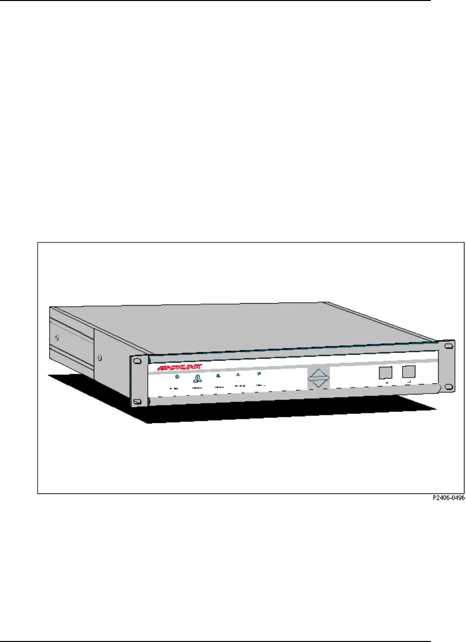
The AirLink Pro T1/E1 Rack Mount (Figure 1-1) unit is a rack mount unit that
mounts in a 19 or 23 inch equipment rack or cabinet. The design of the unit can be
aisle or flush mounted. Status and Alarm LEDs are duplicated on the unit’s
rear panel so that it can be flush mounted against a wall.
Figure 1-1
AirLink Pro T1/E1 Rack Mount - Full View

AirLink Pro T1/E1 Rack Mount Installer’s Guide
Product Description
Rev. B - 1/97 1-3
Features and Capabilities
The AirLink Pro T1/E1 Rack Mount supports a range of sophisticated control
capabilities and options, including:
❚Remote control of far-end
❚Built-In Testing Equipment (BITE)
❚Flexible, interactive user interface through an ASCII terminal
❚Easily modified configuration parameters
❚Local and remote monitoring, diagnostic, and maintenance capabilities
❚Separate end-to-end communication channel for control and order wire
signals. Control signals and order wire voice signals do not disturb the T1
channel
❚Every radio-frequency (RF) burst verified by an error-checking algorithm
The AirLink Pro T1 and E1 are similar radio units with minor differences in
their internal structures. These are:
❚The AirLink Pro T1 and E1 have different internal clock oscillators
❚The AirLink Pro T1 supports the Bipolar with 8-Zero Substitution (B8ZS)
coding format
❚The AirLink Pro E1 supports the High Density Bipolar 3 (HDB3)
coding format
❚The AirLink Pro E1 allows an electrical-interface option between Balanced
and Unbalanced
❚The AirLink Pro T1 operates at 1.544 Mbps and the E1 at 2.048 Mbps
❚ The operating range between two AirLink Pro T1 units is up to 40 km and
that of two E1 units is 35 km
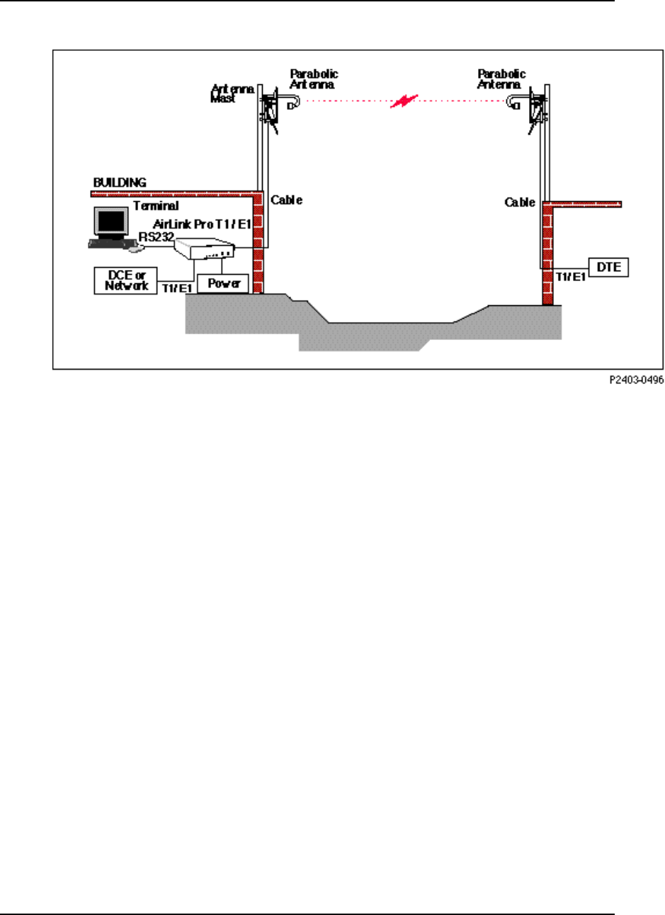
In a typical installation, an AirLink Pro T1 or E1 pair is installed between a
user’s communication facility—Data Circuit Equipment (DCE) or network—and
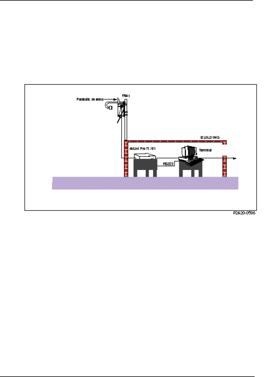
the Data Terminating Equipment (DTE). Figure 1-2 shows the AirLink Pro
T1/E1 Rack Mount in a typical operating environment.
AirLink Pro T1/E1 Rack Mount Installer’s Guide
Product Description
Rev. B - 1/97
1-4
Figure 1-2
Typical AirLink Pro T1/E1 Rack Mount Operating Environment
The AirLink Pro T1/E1 Rack Mount link is effectively transparent to the T1/E1
equipment on either end:
❚Accepts T1/E1 as input
❚Presents T1/E1 as output
AirLink Pro T1 operation is independent of the protocol used, so the AirLink Pro
T1 supports both the Bipolar with Eight-Zero Substitution (B8ZS) and the
Alternate Mark Inversion (AMI) coding formats. The AirLink Pro E1 supports
both the High Density Bipolar 3 (HDB3, and AMI) coding formats. These
formats do not interfere with the framing and maintenance channel used
between T1/E1 links so the AirLink Pro T1/E1 Rack Mount works with Extended
Frame format, ISDN Primary Rate Services, and so on.
The AirLink Pro T1/E1 Rack Mount provides full-duplex, radio-to-radio
communication that follows a Ping-Pong analogy: while one unit transmits a
radio burst, the other unit receives that burst. After the other unit receives a
complete burst, it waits through a guard interval before turning on its
transmitter and transmitting its burst.
The ping-pong radio-to-radio communication is invisible to the T1/E1
equipment on either end of the link because the digital buffering of the AirLink
Pro T1/E1 Rack Mount produces a smooth T1/E1 bit stream at the user interface.

AirLink Pro T1/E1 Rack Mount Installer’s Guide
Product Description
Rev. B - 1/97 1-5
Buffering is only a few milliseconds, so no perceptable degradation occurs to
voice or data communications.
AirLink Pro T1/E1 Rack Mount Antenna
The antenna is usually a two-foot or four-foot solid-parabolic dish for the 5.7
GHz C-band, with a narrow beam and high gain. For other kinds of antennas,
contact your distributor.
The AirLink Pro T1/E1 Rack Mount ASCII Terminal User Interface
The AirLink Pro T1/E1 Rack Mount ASCII terminal user interface is an
EIA/TIA-232 interface that allows a terminal device or personal computer to
control and monitor AirLink Pro T1/E1 Rack Mount operation at either end of
the link. The connection to the EIA/TIA-232 interface can be either a direct
connection (device to port), or an indirect connection (device to modem to port)
for dial-up operation.
Programmed Configuration Parameters
AirLink Pro T1/E1 Rack Mount operation is governed by user-selectable
configuration and control parameters that reside in the non-volatile memory of
the unit. These parameters are displayed and controlled through a terminal
device that can access both the local and remote unit. When power is lost and
then restored, the system reconfigures itself from its protected configuration
database.
A long-life lithium battery protects all system configuration settings during
power losses. The battery is part of the non-volatile memory/real-time clock
circuitry on the digital module in the AirLink Pro T1 and has a 10-year storage
life (in the absence of power to the AirLink Pro T1/E1 Rack Mount).
Refer to Chapter 3, Configuration, for more information on changing
configuration parameter settings.
Monitoring and Diagnostic Capabilities
The AirLink Pro T1/E1 Rack Mount system constantly monitors the quality of
the wireless link, checking the receive RF signal level, bit errors, and many
other critical factors. This information is stored in an internal database of
status and performance information that the AirLink Pro T1/E1 Rack Mount
uses, in part, to derive the events that are stored in the event queue. As alarm
events occur, they are signaled through indicators on the front panel of the
AirLink Pro T1/E1 Rack Mount Installer’s Guide
Product Description
Rev. B - 1/97
1-6
AirLink Pro T1/E1 Rack Mount and are entered in the event queue. To report
alarms, attach a modem and dial-out to the maintenance center.
Using the terminal user interface, query either the local AirLink Pro T1/E1
Rack Mount or the remote AirLink Pro T1/E1 Rack Mount for status, performance
and alarm information, and make configuration changes for either the local or
remote end of the link.
The AirLink Pro T1/E1 Rack Mount also provides bit-error and loopback tests to
isolate problems. Initiate tests in the local AirLink Pro T1/E1 Rack Mount or in
the remote AirLink Pro T1/E1 Rack Mount through the terminal user interface.
Refer to Chapter 4, Operations and Maintenance, for information on monitoring
operation and using diagnostic tools and procedures.
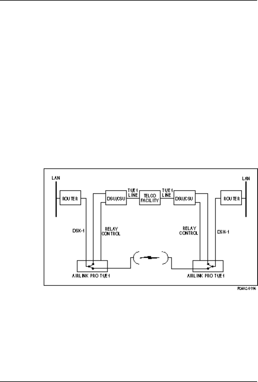
T1/E1 Link Backup Capability
The T1/E1 link backup capability built into the AirLink Pro T1/E1 Rack Mount
enables an AirLink Pro T1/E1 Rack Mount pair to provide a parallel T1/E1
path (the RF link) to a standard T1/E1 line (see Figure 1-3).
Figure 1-3
A Point-to-Point Backup Link
Under normal operating conditions, the primary (protected) T1/E1 line is routed
to an external device such as a CSU through the AirLink Pro T1/E1 Rack Mount
and carries its normal T1/E1 traffic.
In the event of a fault in the primary T1/E1 link, each DSU/CSU generates a
relay control signal that is transmitted to the attached AirLink Pro T1/E1 Rack

AirLink Pro T1/E1 Rack Mount Installer’s Guide
Product Description
Rev. B - 1/97 1-7
Mount units. The AirLink Pro T1/E1 Rack Mount pair switch the protected
T1/E1 line to provide a protected bypass T1/E1 path.
The backup switch can be opened or closed by an external switch or relay wired
to the CSU SEL connector on the rear panel of the AirLink Pro T1/E1 Rack
Mount.
Alarm Relay Contacts
Major and minor alarm contacts are built into the AirLink Pro T1/E1 Rack
Mount. If an alarm occurs such that an entry is put into the event queue, the
alarm contacts switch to the alarm state for as long as the alarm event persists.
For more information on the AirLink Pro T1/E1 Rack Mount alarm relay
contacts, refer to Chapter 2, Installation and System Administration.
Order Wire Interface
The Order Wire interface is an end-to-end voice communication channel that is
carried on the radio link between the local and remote AirLink Pro T1/E1 Rack
Mount units. Maintenance and service personnel can connect telephones to order
wire ports on the local and remote AirLink Pro T1 units and have direct voice
communication between the local and the remote site.
Order Wire communication can only occur when there is an active radio link
between the local and remote AirLink Pro T1/E1 Rack Mount units (refer to
Chapter 2, Installation and System Administration). The Order Wire channel
is outside of the T1/E1 channel and does not affect the user’s data. The Order
Wire can also be used with 4-wire modems in a large network management
system.
Fail-Safe Link
A reliable link can be created by eliminating all “single points of failure.” This
is illustrated in Figure 3-1 and discussed in detail in Chapter 3, Point-to-Point
Link.
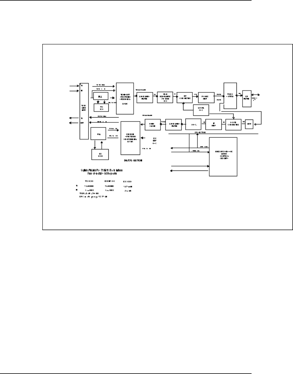
Block Diagram
The following illustration is a functional block diagram of the Cylink AirLink
Pro T1/E1 Rack Mount.
AirLink Pro T1/E1 Rack Mount Installer’s Guide
Product Description
Rev. B - 1/97
1-8
Figure 1-4
Block Diagram of the AirLink Pro T1/E1 Rack Mount

Rev. B - 1/97 2-1
C
CHAPTER
HAPTER 2
2
Installation and
Installation and
System Administration
System Administration
This chapter outlines general planning and the procedures for
unpacking, and installing the AirLink Pro T1/E1 Rack Mount
hardware, connecting cables, and performing power-up checks. This
chapter also contains important instructions regarding safety in setting
up the AirLink Pro T1/E1 Rack Mount system.
Inside this chapter:
Overview ................................................................................ 2-2
Unpacking .............................................................................. 2-2
Identifying Physical Features ........................................... 2-3
Preparing a Place.................................................................2-4
Setting Up the System ...................................................... 2-6
Checking Operation ........................................................... 2-19

AirLink Pro T1/E1 Rack Mount Installer’s Guide
Installation and System Administration
Rev. B - 1/97
2-2
Overview
This chapter discusses the general technical requirements of antenna and RF
transmission line installation,and focuses on the task of installing the AirLink
Pro T1/E1 Rack Mount system at each end of the communication link,
integrating all of the equipment, and performing a system check and alignment
before turning the system over to normal customer traffic.
The components of AirLink Pro T1/E1 Rack Mount system are:
❚AirLink Pro T1/E1
❚AirLink Pro T1/E1 Rack Mount antenna and antenna cable
Depending upon your system plan, you will be installing all or some of these
AirLink Pro T1/E1 Rack Mount system components at each end of a link. The
following sections describe both required and optional system components.
Unpacking
The first step in the installation process is to take all of the materials out of
the shipping carton(s) and check that you have everything shown on the
packing list(s). If something is missing, contact your local distributor. Inspect
the unit for any possible damage.
If you discover shipping damage, repack the unit and notify the shipping
representative.
NOTE Save the shipping cartons and packing materials. You will need the carton and materials if
you need to ship your equipment.
After unpacking and confirming the contents of the shipment, place the AirLink
Pro T1/E1 Rack Mount system components on a flat surface to allow enough space
to work around them.
AirLink Pro T1/E1 Rack Mount Installer’s Guide
Installation and System Administration
Rev. B - 1/97 2-3
Identifying Physical Features
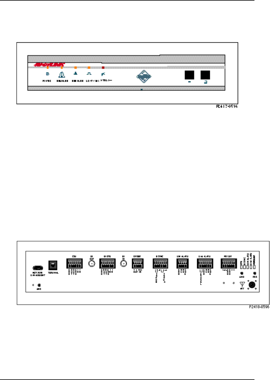
Figure 2-1
AirLink Pro T1/E1 Rack Mount Front Panel
Front Panel
The AirLink Pro T1/E1 Rack Mount front panel (Figure 2-1) consists of a metal
panel that contains five status and alarm LEDs identified with graphical icons
and two RJ-11 jacks.
Rear Panel
The AirLink Pro T1/E1 Rack Mount rear panel (Figure 2-2) consists of a metal
panel containing four external equipment connectors, seven terminal blocks, and
an n-type antenna connector. Table 2-1 lists the rear-panel connectors and
describes their functions.
Figure 2-2
AirLink Pro T1 /E1 Rack Mount Rear Panel

AirLink Pro T1/E1 Rack Mount Installer’s Guide
Installation and System Administration
Rev. B - 1/97
2-4
Table 2-1
AirLink Pro T1/E1 Rack Mount Rear-Panel Connectors
Connector Type Function
Network Management 9-Pin Male
Subminiature D Connects a modem to the AirLink Pro
T1/E1.
Terminal RJ - 11 Terminal connection
CSU 6-Pin Captive
Wire Terminal
Block
Connects the T1/E1 Line from an external
device such as a CSU. Used for wire line
backup only.
E1 Out BNC Not used for T1 unit; In E1 unit, used for
configuring Unbalanced Interface option
DTE 4-Pin Captive
Wire Terminal
Block
T1/E1 connection to the DTE
E1 In BNC Not used for T1 unit; In E1 unit, used for
Unbalanced Interface option
Order Wire 4-Pin Captive
Wire Terminal
Block
Connection for Four wire Order Wire unit
BSYNC 6 Pin Captive
Wire Terminal
Block
Burst sync connection
Minor Alarm 4-Pin Captive
Wire Terminal
Block
Minor alarm relay connection
Major Alarm 6-Pin
CaptiveWire
Terminal Block
Major alarm relay connection
Power 6-Pin Captive
Wire Terminal
Block
Power connection
Antenna N type female Antenna connection
Preparing a Place
Because of the special planning requirements associated with installing a
microwave system, review some of the general guidelines regarding
installation preparation to ensure that the site is suitable to the purpose.

AirLink Pro T1/E1 Rack Mount Installer’s Guide
Installation and System Administration
Rev. B - 1/97 2-5
General Physical and Environmental Characteristics
The AirLink Pro T1/E1 Rack Mount radio unit measures approximately 17
inches wide, 3 inches high, and 10 inches deep, and weighs approximately 10
pounds.
Lightning Protection
The AirLink Pro T1/E1 Rack Mount is provided with secondary protection on all
signal leads to the printed circuit assemblies in the unit. If the AirLink Pro
T1/E1 Rack Mount system is being installed in an area where lightning can be a
problem, primary protection, such as gas tubes or spark gaps, is required (Cylink
distributors can provide these).
Rack-Mounting
The AirLink Pro T1/E1 Rack Mount mounts indoors in a 19-inch or 23-inch
equipment rack or cabinet. The rack-mount hardware kit, which consists of a
pair of mounting brackets and all required fasteners, is included in the shipping
carton with the AirLink Pro T1/E1 Rack Mount.
Power and Grounding Requirements
The AirLink Pro T1/E1 Rack Mount operates at 24VDC or 48VDC. Either the
positive or negative input is connected to the ground, or left floating. External
circuit protection not exceeding 2 amps is required.
Table 2-2
Power Requirements
Input Voltage 21 to 56 VDC
Input Power 25 Watts
Input Current 1.0 Amps @ 24 Volts
500 Ma @ 48 Volts
Input Polarity Input is floating. Either input may be grounded
Input Protection Nominal fuse = 2.0 A Slow Blow
Input Reverse
Voltage Protection Provided. Series diode. No current will flow if the
input voltage is reversed.

AirLink Pro T1/E1 Rack Mount Installer’s Guide
Installation and System Administration
Rev. B - 1/97
2-6
NOTE No internal fusing is provided, because to do so would violate the specifications of
UL1459 section 70. (No fusing is allowed in the grounded side of a DC input circuit unless
the hot side is also fused.) When the fuse in the hot side blows, the fuse in the grounded
input must
also
blow. Since this equipment accepts either polarity, external circuit
protection
must be
provided in the hot side of the feeder circuit.
Setting Up the System
The following sections outline the procedures for installing, cabling, and
bringing up an AirLink Pro T1/E1 Rack Mount system. Some of the steps require
special knowledge, experience, tools, and assistance from another person.
Installing the Antenna
Antennas are generally installed by persons who have the knowledge,
experience, and tools to handle the somewhat specialized task. The following
sections are intended as a general summary of the process, and not as a complete
description. A successful antenna installation effort is the culmination of all
the site and route preparation, and path analysis.
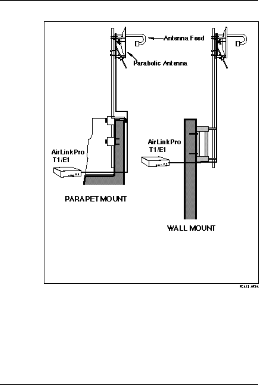
Typical Antenna Mounts
An antenna for a microwave system such as the AirLink Pro T1/E1 Rack Mount
is typically equipped with mounting hardware that allows the antenna to
attach to a length of pipe that can then be mounted in several ways, depending
upon the user requirements, site conditions, and local building codes (see
Figure 2-3).
AirLink Pro T1/E1 Rack Mount Installer’s Guide
Installation and System Administration
Rev. B - 1/97 2-7
Figure 2-3
Typical Antenna Mounts

AirLink Pro T1/E1 Rack Mount Installer’s Guide
Installation and System Administration
Rev. B - 1/97
2-8
System Grounding
Direct grounding of the antenna, mast, and tower provides some protection
against lightning strikes and static buildup. A direct electrical connection
should be made to a suitable grounding rod at the base of the tower or mast using
at least #10 AWG ground wire, or its equivalent, and non-corrosive hardware.
For details and safety standards, consult the appropriate electrical code or a
similar document. Use lightning arrestors in appropriate places.
Aligning the Antenna
In order for an AirLink Pro T1/E1 Rack Mount pair to operate correctly, the
local antenna and the remote antenna must be aligned so that the signals from
one antenna are aimed directly at the center of the other antenna. Correct
antenna alignment maximizes the signal received at both ends of the radio
link. An outline of the antenna alignment procedure is at the end of this
chapter.
Installing the AirLink Pro T1/E1 Rack Mount
The following illustration shows how to connect the mounting ears on the unit
(center-mounted or flush-mounted).

AirLink Pro T1/E1 Rack Mount Installer’s Guide
Installation and System Administration
Rev. B - 1/97 2-9

AirLink Pro T1/E1 Rack Mount Installer’s Guide
Installation and System Administration
Rev. B - 1/97
2-10
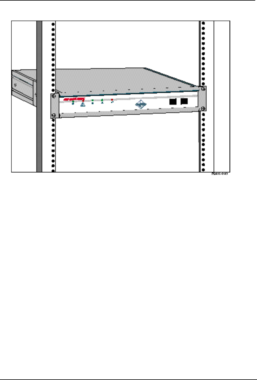
The AirLink Pro T1/E1 Rack Mount can be installed into a standard 19-inch or
23-inch equipment rack using the rack-mount hardware included with the unit.
It requires 4U (7.0”) of rack mounting space, of which 1U space above and below
the unit is necessary for proper ventilation. Two standard blank panels can be
used over the openings.
To mount the AirLink Pro T1/E1 Rack Mount in an equipment rack:
1. Place the AirLink Pro T1/E1 Rack Mount on a table or bench.
2. Lay out the pieces of the rack mount hardware kit.
The rackmount hardware kit should contain the following parts:
❚Two 1-inch increment mounting brackets for 23-inch rack mount
❚Two EIA mounting brackets for 19-inch rack mount
❚Eight 10-32 x 3/8” Phillips pan-head screws, lock washers, and flat
washers
3. Orient the mounting brackets for front- or mid-mounting.
4. Attach the brackets to the AirLink Pro T1/E1 Rack Mount with the screws
provided in the hardware kit.
5. Position the AirLink Pro T1/E1 Rack Mount in the equipment rack and
fasten with screws.
AirLink Pro T1/E1 Rack Mount Installer’s Guide
Installation and System Administration
Rev. B - 1/97 2-11
Figure 2-4
23” Rack Mount
Connecting the Antenna Cable
To connect the antenna cable to the AirLink Pro T1/E1:
1. Locate the N-type connector on the rear panel of the AirLink Pro T1/E1
Rack Mount (see Figure 2-2).
2. Plug the RF cable connector firmly into the N-type jack connector and hand-
tighten the cable connector shell onto the jack connector collar.
3. Verify that the cable connector is seated securely and that the cable is not
kinked.
4. Recommend 1/2 or 7/8-inch case. Check the rating for 6 Ghz operation.
5. Recommend using short piece of more flexible coaxial to connect to the
AirLink, such as the RG-6/U or the RG-59/U from Cylink.

AirLink Pro T1/E1 Rack Mount Installer’s Guide
Installation and System Administration
Rev. B - 1/97
2-12
T1 DTE Line Connection
To connect the T1 line cable to the DTE:
1. Locate the DTE terminal block on the Airlink Pro T1/E1 Rack Mount rear
panel (see Figure 2-2).
2. Prepare the cable wire so that individual leads are separate. Strip a small
portion of insulation off each wire lead.
3. With the help of a screw driver, push back one of the plastic levers located
on the terminal block.
The following is a list of some suitable coaxial cables:
Type Manufacturer Part
Number AWG ATTN1UL Rating2
RG-6/U Belden 9248 22 (7/30) .3 dB CM
RG-6/U Belden 88248 22 (7/30) .3 dB CMP
RG-59/U Belden 9259 18 (solid) .3 dB CM
RG-59/U Belden 88259 18 (solid) .3 dB CMP
1 Attenuation per 100 at 1 Mhz.
2 U1 Rating System:
CM= General purpose, vertical tray. Tested per UL-1581.
CMP=Plenum Rated. Tested per UL-910.
The following is a list of some suitable cables for the T1 or E1 Balanced.
The cable type usually specified for indoor T1 use is Western Electric ABAM or
equivalent. An equivalent cable is General Cable Specification 4162D. The
characteristics of these two cables are listed in the table. These cables are
rated in-building use and in-vertical risers and are not rated for use in
plenumbs. Both of these cables use solid wire.
Cable Gauge Impedance Loss at 1 Mhz
ATAM 22 100 Ohms 4.0 dB
GT4162 22 100 Ohms 6.0 dB
A second class of indoor cable is 100 Ohms stranded, shielded 24 ga. These
cables have a characteristic impedance of 100 Ohms and a loss at 1 Mhz of
about 7 dB per 1000’. Representative cables of this type are listed in the
following table. These cables are also suitable for E1 applications.

AirLink Pro T1/E1 Rack Mount Installer’s Guide
Installation and System Administration
Rev. B - 1/97 2-13
Belden Part No. 8729 (UL Rating CMP (Plenum))
Individually shielded twisted pairs.
Berk-Tek Part No. 230249 (Plenum)
Berk-Tek Part No. 230131 (Non Plenum)
These cables have an overall foil shield.
The recommended E1 cable: The E1 signal can be either unbalanced, in which
case the coaxial cables listed can be used or it can be unbalanced, in which case
the balanced twisted pair cables can be used.
4. While holding it in this position, insert one of the leads of the cable into
the spring pin connector, below the lever.
5. Release the lever.
6. Repeat Steps 3, 4 and 5 to connect each lead.
7. Ensure that each cable lead is securely held by the spring pin connectors.
T1 Backup Connections
1. Locate the CSU terminal block on the AirLink Pro T1/E1 Rack Mount rear
panel (see Figure 3-2).
2. Follow the same procedure used for connecting T1/E1 DTE line.
3. Locate the fault signal cable connector from the external device.
4. Connect the fault signal cable to the CSU -SEL connector on the major
Alarm terminal block.
In the event of a fault in the primary T1/E1 link, each CSU generates a relay
control signal that is transmitted to the attached AirLink Pro T1/E1 Rack
Mount. The T1/E1 pair switch the protected primary line in, to provide a
protected bypass T1/E1 path.
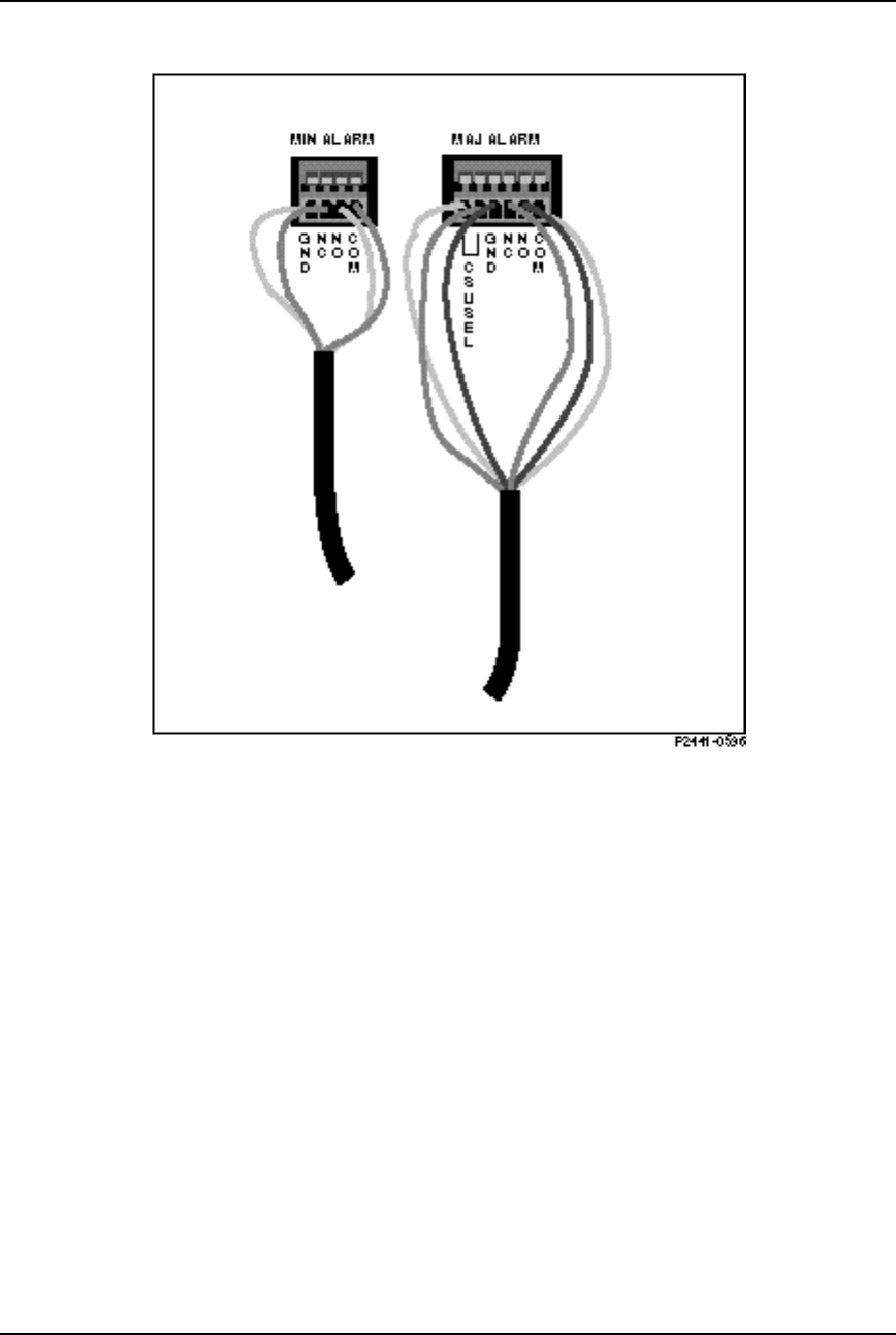
Alarm Relay Contact Connections
If you have an application that uses the alarm relay contacts in the MAJOR &
MINOR ALARM captive-wire terminal block on the rear panel of the AirLink
Pro T1/E1 Rack Mount, connect the device cable to the ALARM-C and ALARM-
NC or ALARM-NO contacts in the MAJOR & MINOR ALARM captive-wire
terminal block (see Figure 2-5).
AirLink Pro T1/E1 Rack Mount Installer’s Guide
Installation and System Administration
Rev. B - 1/97
2-14
Figure 2-5
Alarm Relay Contacts
The major and minor alarm contacts built into the AirLink Pro T1 are SPDT
relay contacts rated at 8 VA (0.25 A maximum at 100 VDC maximum) isolated
from the ground. The alarm relays are de-energized when the AirLink Pro
T1/E1 Rack Mount is in an alarm state: the NO contact is closed; the NC contact
is open.
If an alarm occurs such that an entry is put into the event queue, the alarm
contacts switch to the alarm state for as long as the alarm event persists or until
the alarm is reset.
Terminal Connection
A simple ASCII terminal or personal computer can be connected to the RJ-11
Terminal Jack on the front or rear panels of the AirLink Pro T1/E1 Rack Mount
to monitor and configure its operation. A DB9 to RJ-11 adapter is included. In a
hub installation involving a number of AirLink Pro T1/E1 Rack Mount pairs, the
AirLink Pro T1/E1 Rack Mount Installer’s Guide
Installation and System Administration
Rev. B - 1/97 2-15
terminal device can be “shared” across all the AirLink Pro T1 systems by a
terminal switching device.
A terminal device or a personal computer can have specific data cabling
requirements (refer to Appendix B, Specifications, for connector pin
assignments), and usually requires a grounded alternating current power outlet.
An adapter kit that connects between the AirLink Pro T1/E1 Rack Mount
terminal port and a male DB-9 connector is shipped with the equipment.
Figure 2-6
Terminal Connection to the AirLink Pro T1/E1 Rack Mount
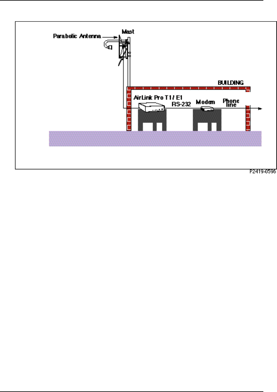
Remote Connection
A remote terminal or personal computer can be connected to the Terminal port on
the front or rear panels of the AirLink Pro T1/E1 Rack Mount unit through a
modem (Figure 2-6). A modem requires a dedicated telephone line with a
modular RJ-11 jack as well as a source of power, usually a standard 115 VAC
grounded outlet.
AirLink Pro T1/E1 Rack Mount Installer’s Guide
Installation and System Administration
Rev. B - 1/97
2-16
Figure 2-7
Modem Connection to the AirLink Pro T1/E1 Rack Mount
Order Wire Connection
The Order Wire interface is a 64 kbps pulse modulation (PCM) voice
communication channel. This part of the AirLink Pro T1/E1 Rack Mount RF
protocol does not use any part of the 1.544 Mbps T1 channel or the 2.048 Mbps E1
channel. The Order Wire interface meets V.21 and V.32 modem specifications.
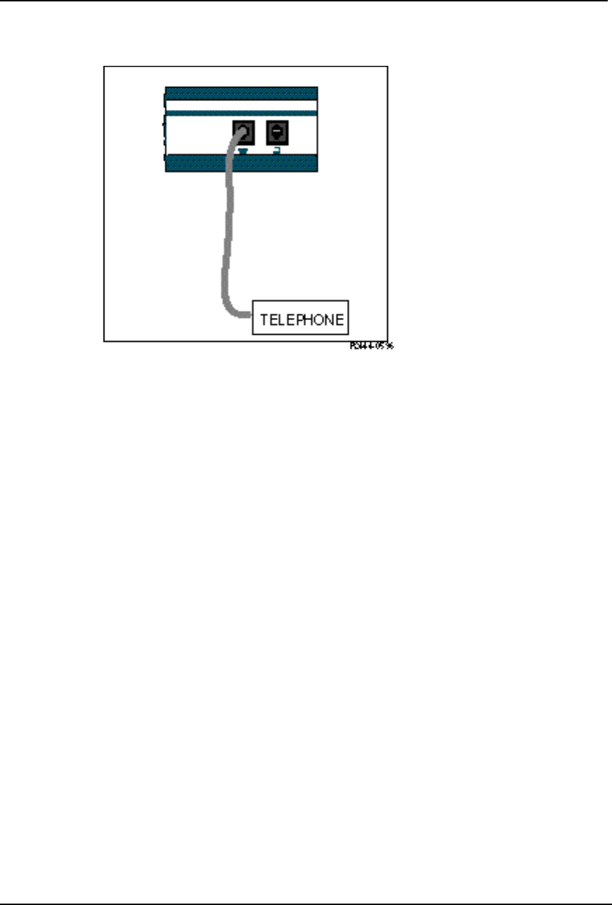
A standard telephone (2 wire interface) can be plugged in to the Order Wire
jack on the front panel ( Figure 2-3). A telephone is required at each end of the
link.
AirLink Pro T1/E1 Rack Mount Installer’s Guide
Installation and System Administration
Rev. B - 1/97 2-17
Figure 2-8
Two-Wire Order Wire Connection
Order Wire communication can only occur when there is an active radio link
between the local and remote AirLink Pro T1/E1 Rack Mount units and the RSQ
is 6 or higher. Communication across the order wire interface is initiated by
picking up the telephone at either end of the link. When the RSQ is below 6,
the AirLink Pro T1/E1 Rack Mount software mutes the order wire. Picking up
the order-wire telephone causes an audible tone (beeping ) at the remote
Airlink Pro T1/E1 Rack Mount. This tone continues until the telephone at the
remote end is picked up.
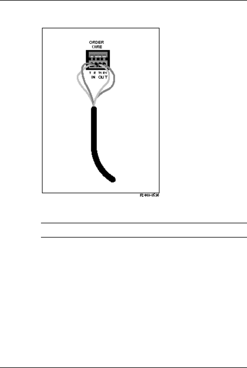
An external order wire unit can be connected to the designated terminal block on
the rear panel. When an external 4 wire interface is used, the order wire unit
provides its own signaling. The 4-wire interface allows multiple T1/E1 units at
a hub to be connected through a 4-way or 8-way 4-wire bridge (Figure 2-11).
Connect the input pair of the order wire to the T & R located on the ORDER
WIRE terminal block and connect the output pair to the T1 & R1.
Set the external order wire to transmit and receive at 0 dBm. The type of order
wire interface (2 or 4-wire) is selected from the Command Line Interface
Configuration screen. (See “Setting Link Parameters” in Chapter 3,
Configuration).
AirLink Pro T1/E1 Rack Mount Installer’s Guide
Installation and System Administration
Rev. B - 1/97
2-18
Figure 2-9
Four-Wire Order Wire Connection
CAUTION The order wire interface must not be connected directly to the Public Switched
Telecommunications Network.
AirLink Pro T1/E1 Rack Mount Installer’s Guide
Installation and System Administration
Rev. B - 1/97 2-19
External Power Supply Connection
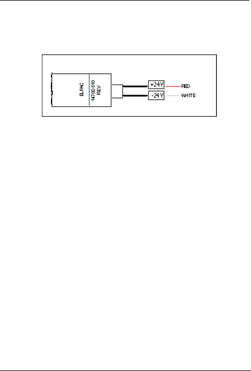
Figure 2-10
ELPAC Power Supply
For the ELPAC Power Supply
1. Locate the Power terminal block on the unit’s rear panel and insert the red
wire of the power supply into the +V spring pin connector of the terminal
block.
2. Insert the white wire into the -V spring pin connector of the terminal block.
3. Ensure that the two wires are securely held by the connectors.
AirLink Pro T1/E1 Rack Mount Installer’s Guide
Installation and System Administration
Rev. B - 1/97
2-20
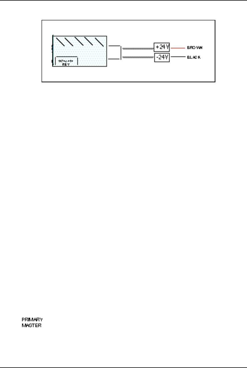
Figure 2-11
FORTRON Power Supply
For the FORTRON Power Supply
1. Locate the Power terminal block on the rear panel of the unit and insert the
brown wire of the power supply into the +V of the terminal block.
2. Insert the black wire into the -V spring pin connector of the terminal block.
3. Ensure that the two wires are securely held by the connectors.
Wiring for Burst Synchronization
When you have either a hub configuration or a repeater site (more than one
AirLink Pro T1/E1 Rack Mount unit operating from the same central site), one of
the units must be set up as the source for burst synchronization. Refer to Chapter
3, Configuration, for Hub and Repeater configurations.
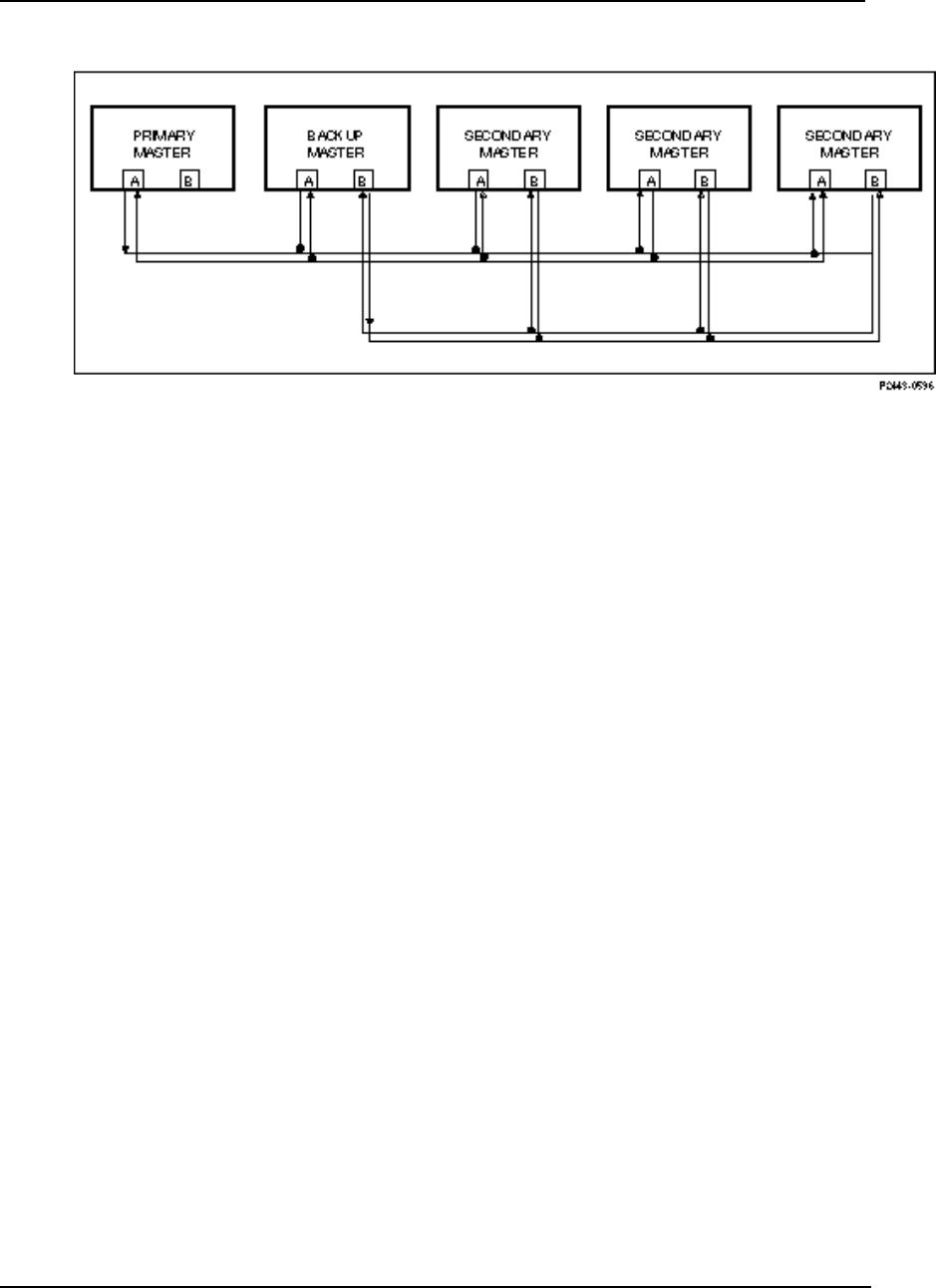
Installing the Burst Sync Wiring
The burst synchronization connections are made using unshielded twisted pair
wires. The equipment should be physically located as shown in Figure 2-12.
The primary and the backup masters should be the first units in the group. If
the distance between the primary master and the last secondary master is
greater than 100 ft, the burst sync bus(es) should be terminated at this unit (the
last secondary master).
AirLink Pro T1/E1 Rack Mount Installer’s Guide
Installation and System Administration
Rev. B - 1/97 2-21
Figure 2-12
Burst Sync Wiring
Terminating the Burst Sync Bus
The burst sync bus is terminated by inserting a short jumper wire in the TERM A
and TERM B locations as defined by the rear panel labels.
Checking Operation
During start-up an AirLink Pro T1/E1 Rack Mount pair:
❚Establishes the radio link between the two radio units
❚Starts transferring data
When each radio unit is powered up, a power-on self-test begins that
determines whether the unit’s hardware and software are operating within
the required limits. When the test succeeds, the designated master unit begins
transmitting, attempting to establish a RF link with the slave unit.
AirLink Pro T1/E1 Rack Mount units leave the factory configured as master
units in a point-to-point configuration; configure one of the units as a slave.
Initial Unit Configuration
In a new point-to-point link installation, the configuration on one end must be
changed to application 6 (Slave Unit in a Point-to-Point Link, refer to
“Application” in Chapter 3).

AirLink Pro T1/E1 Rack Mount Installer’s Guide
Installation and System Administration
Rev. B - 1/97
2-22
In a new hub installation, the units at the hub must all be masters, and the
corresponding remote units must be slaves. At a hub, set up each individual link
first as a point-to-point link and then align each link separately with all the
other AirLink Pro T1/E1 Rack Mount units turned off. After all the link pairs
have been configured and aligned as point-to-point links, you can then change
configurations for hub operation.
In a new repeater installation, treat each link segment as a point-to-point link,
progressing from the near-end to the far-end sites. After all the link pairs have
been configured and aligned as point-to-point links, you can change
configuration for repeater operation.
For more information about applications and burst synchronization, refer to
“Application Examples” in Chapter 3, Configuration.
No radio link exists until the AirLink Pro T1 pairs have been configured and
aligned, all system configuration must be done individually at each unit. After
a radio link is established between the units of an AirLink Pro T1 pair, the
remote unit can be configured from the local site across the radio link.
To configure one end of the link as a slave:
1. Connect a terminal to the Terminal port on the slave AirLink Pro T1/E1
Rack Mount or to the Terminal port on the AirLink Pro T1/E1 Rack Mount
attached to the slave unit.
The terminal must be set up to operate according to the attributes described
in “ Connecting a Terminal,” in this chapter.
2. Type the following command at the prompt:
AIRLINK PRO T1/E1> set application 6
The text you type is in boldfaced type; enter the spaces as shown.
3. To verify the configuration change, type the following command at the
prompt:
AIRLINK PRO T1/E1> get configuration
The terminal displays the configuration of the unit, similar to the
following:
AIRLINK PRO T1/E1> Get Configuration
Site Name:
Application: 6. Slave Unit in a Point-to-Point Link
Burst Mode: Normal
Coding: B8ZS or (HDB3)

AirLink Pro T1/E1 Rack Mount Installer’s Guide
Installation and System Administration
Rev. B - 1/97 2-23
Equalization: 0 - 133 feet
PN Code: 1
RF Power: 10 dBm
Alarm Reporting: Immediate
Alarm Level: Status
Date/Time: May 1 1996 10:35:00
NOTE You might need to alter more configuration values in order to ensure correct operation,
during your AirLink Pro T1/E1 Rack Mount installation. Refer to Chapter 3 for more
information on configuring the AirLink Pro T1/E1 Rack Mount.
Aligning the Antenna
After the link pair has been turned on and configured, the antennas must be
aligned. Since most AirLink Pro T1/E1 Rack Mount paths will be line-of-sight
paths, visually align the initial antenna. In most cases, this rough alignment is
sufficient for radio units to acquire radio synchronization lock.
NOTE When the radio link between two units is active, telephones can be plugged into the OW
jacks on the AirLink Pro T1/E1 Rack Mount units permitting persons at the two sites to talk
to one another. Picking up the order wire telephone causes an audible tone (pulsed
beeping) at the remote AirLink Pro T1/E1 Rack Mount unit. This tone continues until the
telephone at the other end is picked up.
To “fine tune” the antenna alignment, perform the following procedure:
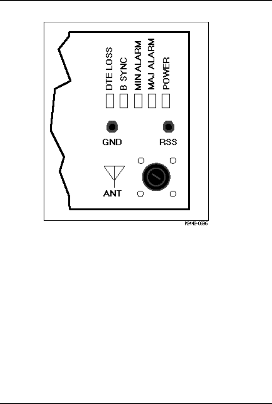
1. Insert the probes of a DC voltmeter into test points (RSS) and (ground) on
the AirLink Pro T1/E1 Rack Mount (see Figure 2-11).
AirLink Pro T1/E1 Rack Mount Installer’s Guide
Installation and System Administration
Rev. B - 1/97
2-24
Figure 2-13
Test Point Locations
2. Swing the antennas on both ends of the link horizontally and vertically
(but not at the same time!) until the observed voltage peaks.
Swing the antennas through the main lobe and both side lobes to check that
the antenna is aligned on the main lobe and not one of the side lobes.
After you align the antenna, use the terminal query status and query
performance commands to check the receive signal strength (Rx Power) and
the receive signal quality (RSQ). Compare the receive signal level to the
expected signal level based on the path calculations.
3. Type the following command at the AirLink Pro T1/E1 Rack Mount prompt:
AIRLINK PRO T1/E1> query status

AirLink Pro T1/E1 Rack Mount Installer’s Guide
Installation and System Administration
Rev. B - 1/97 2-25
The system displays a list of status information similar to the following:
AIRLINK PRO T1/E1> query status
Site Name: Sunnyvale 2
DTE Loss: NO
Radio Sync Loss: NO
Burst Sync Loss: N/A
Test in Progress: FE Radio Remote Loop
DTE AIS: OFF
RF AIS: OFF
Tx Fail: NO
Rx Power: -60.5 dBm
Tx Power: 12.0 dBm
Temperature: 5 C
4. Type the following command at the AirLink Pro T1/E1 Rack Mount prompt:
AIRLINK PRO T1/E1> query performance
The system displays a list of status information similar to the following:
AIRLINK PRO T1/E1> query performance
Site Name: Sunnyvale 2
UWER BER: <10E-08
QRSS BER: Unavailable
1 HR ES: 1
1 HR UAS: 0
24 HR ES: 1
24 HR UAS: 0
RSQ: 10
The Receive Signal Quality (RSQ) is a figure of merit that is normalized on a
scale of 1 to 10, and is a function of the receive signal-to-noise and signal-to-
interference ratio. A very strong signal that is severely corrupted with
interference results in a normal receive signal power indication and a low RSQ
number.
Assuming that the T1/E1 lines to and from the AirLink Pro T1/E1 Rack Mount
units are okay, T1/E1 data transfer begins as soon as the RF link is established.
If you need to alter other configuration values, refer to Chapter 3,
Configuration, for configuration procedures.

Rev. B - 1/97 3-1
C
CHAPTER
HAPTER 3
3
Configuration
Configuration
This chapter describes how to use the AirLink Pro T1/E1 Rack Mount
command-line terminal user interface to set and change configuration
parameters. The information in this chapter includes descriptions of all
the AirLink Pro T1/E1 Rack Mount configuration commands and
options, and lists the default configuration settings.
Inside this chapter:
Overview ................................................................................ 3-2
Using the ASCII Terminal Interface ................................ 3-2
Setting Administrative Parameters ............................... 3-5
Setting T1/E1 Line Parameters .................................... 3-11
Setting Link Parameters ................................................. 3-13
Setting Alarm Control Parameters ............................. 3-28
Setting Modem Parameters.............................................3-22
Getting AirLink Pro T1 Configuration
Information .................................................................... 3-30
Command Keywords and
Operands ....................................................................... 3-41

AirLink Pro T1/E1 Rack Mount Installer’s Guide
Configuration
Rev. B - 1/97
3-2
Overview
To configure the AirLink Pro T1/E1 Rack Mount, connect an ASCII terminal or a
personal computer to the Terminal port of the AirLink Pro T1/E1 Rack Mount.
The AirLink Pro T1/E1 Rack Mount ASCII terminal interface provides a
command-line interface for manipulating the operation of the AirLink Pro
T1/E1 Rack Mount, including configuring operational parameters, monitoring
operation, and responding to alarm conditions. The command line interface also
provides an online help facility to aid you in entering commands. You can also
type in a help request for a particular command combination.
You can type a question mark (?) at the end of any command field, and the
command interpreter will display the next valid keyword or operand that you
can enter.
If you press <Return> before the command is complete, the command interpreter
displays the next valid keyword or operand that you can enter. If the command
is complete, the system will execute the command.
The command line interface is described in more detail in the following
sections.
Using the ASCII Terminal Interface
Terminal Setup Requirements
Before connecting the ASCII terminal to the unit, configure the terminal with
the following parameters:
Terminal Mode = VT100
Column = 80
Autowrap = ON
Monitor Mode = OFF
Cursor Keys = Normal
Newline Mode = ON
Character Set = DEC Supplemental
Key Code = ASCII
Break key = ON
Minimum Break Length = 2 character times (17 msec.)
Data/Parity = 8/No Parity
Stop Bits = 1

AirLink Pro T1/E1 Rack Mount Installer’s Guide
Configuration
Rev. B - 1/97
3-3
Transmit Rate = 19200, 9600, 4800, 2400, or 1200 bps
Auto Answerback = OFF
Comm = FDX (No Echo)
RS232 Data Leads Only (RxD and TxD)
Local Echo = OFF
To connect the terminal, follow these steps:
1. Connect the terminal (or a computer in terminal emulation mode) to the
Terminal port with the EIA/TIA-232 cable as described in Chapter 2.
2. Turn on the terminal; adjust the contrast and brightness as required.
The AirLink Pro T1/E1 Rack Mount terminal interface software contains an
autobaud feature that automatically attempts to detect the operating baud
rate of the attached terminal device.
3. Press <Break> then <Return> on the terminal keyboard.
Pressing <Break> at the terminal puts the AirLink Pro T1/E1 Rack Mount
terminal interface software in “hunt” mode, where it looks for carriage
return (<Return>) characters at the attached terminal.
If the terminal is set for 19200, 9600, 4800, 2400, or 1200 bps, the terminal
interface software learns the operating baud rate by starting at 19200 bps
and dropping to the next lower speed in the sequence until it recognizes a
<Return> character.
When the AirLink Pro T1/E1 Rack Mount terminal interface detects a
<Return> keystroke, it displays the AirLink Pro command-line prompt:
AIRLINK PRO T1> or AIRLINK PRO E1>
Pressing <Break> puts the terminal interface software back into hunt mode.
If the prompt does not appear, press <Break>once, then press <Return>
repeatedly at one second intervals until the AirLink Pro T1/E1 Rack Mount
prompt appears. If the prompt does not appear after pressing <Return> six
times, press <Break> and try again.
Command-Line Interface
The command-line interface consists of commands for manipulating the
operation of the AirLink Pro T1/E1 Rack Mount, including configuring
operational parameters, monitoring operation, and responding to alarm
conditions.

AirLink Pro T1/E1 Rack Mount Installer’s Guide
Configuration
Rev. B - 1/97
3-4
Command-Line Format
The general syntax of a command line consists of a basic command keyword
followed by additional keywords and operands that qualify the command
keyword:
BASIC_KEYWORD KEYWORD_1 … KEYWORD_n operand; comment
The command-line format and syntax is based upon the following :
❚Separators: Each keyword or operand must be separated by a separator
character—a space or a TAB character. Extra space characters between two
command elements are treated as one space character.
❚Order: The basic command keyword must be the first word of the command.
All operands that relate to a keyword must immediately follow that
keyword in the prescribed order. Keywords relating to another keyword
must follow that keyword.
❚Comments: In a case where the command line is part of a file that is sent to
the remote interface, you can add comments to a command line by appending
a semicolon character (;) to the end of the command line, followed by the
text of the comment. The command interpreter ignores the semicolon and
any characters following it except <Return>.
❚Length: The maximum keyword length is 15 characters. The maximum
command-line length is 250 characters, including comment text, separator
characters, and <Return>. Any command that exceeds this length is
rejected with an appropriate error message.
❚Short forms of keywords: You can save keystrokes when typing commands
by abbreviating a keyword to the first four characters of the keyword.
❚Case: Commands are not sensitive to case. You can enter keywords as all
upper-case characters, all lower-case characters, or as any combination.
❚Choosing from a list of options: The notation
{ x1 | x2 | ... | xn }
showing numbers or terms separated by vertical bars indicates that you can
select one of the elements in the listed set of x1 to xn. For example, in the set
of options:
{ 0 | 133 | 266 | 399 | 533}
you can choose any one of the listed values.

AirLink Pro T1/E1 Rack Mount Installer’s Guide
Configuration
Rev. B - 1/97
3-5
❚Choosing from a range of numbers: The notation
{n1 .. n2}
indicates that you can specify a number within the range of numbers shown
in the active command context, for example, given the range {0 .. 24}, you
would specify a single number from 0 to 24.
❚Special keystroke sequences:
Press <Ctrl>+R to repeat the previous command.
Press <Esc> to clear the command line and start a new command.
Command Responses
Commands that contain errors or that request information from the unit receive
responses. Commands that set parameters receive a response of "OK" only
when they contain no errors. The following keywords are:
OK Indicates that a command to change system
configuration settings was received correctly and
executed.
SYNTAX ERROR If an entry error is entered, the unit responds with a list
of valid choices.
Setting Administrative Parameters
The AirLink Pro T1/E1 Rack Mount administrative parameters include the
following:
❚Site Name
❚Date and Time
❚Password
Site Name
The site name identifies the role or location of the specified AirLink Pro T1.
This parameter is optional and can be a description of up to 60 alphanumeric
characters.
To set the site name for the local AirLink Pro T1/E1 Rack Mount, type the
following command at the AirLink Pro T1/E1 Rack Mount prompt:

AirLink Pro T1/E1 Rack Mount Installer’s Guide
Configuration
Rev. B - 1/97
3-6
AIRLINK PRO T1/E1> set site name name
where name is any convenient description of up to 60 alphanumeric characters.
For example, to set the site name of the local AirLink Pro T1/E1 Rack Mount to
Sunnyvale 2, type the following command at the AirLink Pro T1/E1 Rack Mount
prompt:
AIRLINK PRO T1/E1> set site name Sunnyvale 2
To set the site name of the remote AirLink Pro T1/E1 Rack Mount, use the
command:
AIRLINK PRO T1/E1> remote set site name name
Date and Time
The date and time in system operations provides a reference in time-stamping
status, performance and alarm information.
To set the date for the local AirLink Pro T1/E1 Rack Mount, type the following
command at the AirLink Pro T1 prompt:
AIRLINK PRO T1/E1> set date date
The operand date is the calendar date, and takes the form mm/dd/yy, where
mm is a number from 1 to 12, dd is a number from 1 to 31, and yy is the last two
digits of the current year.
For example, to set the date of the local AirLink Pro T1/E1 Rack Mount, type
the following command at the AirLink Pro T1/E1 Rack Mount prompt:
AIRLINK PRO T1/E1> set date 9/30/94
To set the date of the remote unit, use the command:
AIRLINK PRO T1/E1> remote set date date
To set the time for the local unit, type the following command at the AirLink
Pro T1/E1 Rack Mount prompt:
AIRLINK PRO T1/E1> set time time
The operand time is a 24-hour clock value that takes the form hh:mm:ss,
where hh is a number from 0 to 23, representing the hour, mm is a number from 0
to 59 representing the minute, and ss is a number from 0 to 59, representing the
second. Seconds are optional; if you do not enter a value for seconds, the system
assumes a setting of 00 seconds.

AirLink Pro T1/E1 Rack Mount Installer’s Guide
Configuration
Rev. B - 1/97
3-7
For example, to set the time of the local AirLink Pro T1/E1 Rack Mount, type
the following command at the AirLink Pro T1/E1 Rack Mount prompt:
AIRLINK PRO T1/E1> set time 10:35:00
To set the time of the remote unit, use the command:
AIRLINK PRO T1/E1> remote set time time
For outdoor use, print (AU) in the Site name when the Access Unit is installed.
NOTE The additional time required to access the remote end of the link is a fraction of a second
and need not be taken into account.
Password
The password is required when the unit is powered on, or after the operator logs
off the system and wants to enter it again. The operator must provide the
correct password to use the GET, SET, QUERY, RESET, TEST and REMOTE
commands.
When the unit is prepared for shipment, it is configured with a null password
as a default. To gain access to the system the first time, press <Return> in
response to the login prompt for the password.
To protect the system, you should change the password at the earliest
opportunity. The new password should be noted and stored in a safe place. After
changing the password, you should test the new password by logging out and in
again.
NOTE If you are unable to use your password or forget your password, contact Cylink Customer
Service for assistance.
A password can be any convenient combination of up to 16 alphanumeric
characters from the set a-z, A-Z, and 0-9. The Password is case sensitive.
To set or change the password for the local unit, type the following command at
the AirLink Pro T1/E1 Rack Mount prompt:
AIRLINK PRO T1/E1> set password
The system prompts you to enter the old password, prompts you to enter the new
password, and then prompts you to enter the new password again, for
confirmation. If the second instance of the new password matches the first

AirLink Pro T1/E1 Rack Mount Installer’s Guide
Configuration
Rev. B - 1/97
3-8
instance of the new password, the new password is accepted. A password can be
any convenient combination of up to 16 alphanumeric characters.
For example, the local AirLink Pro T1/E1 Rack Mount is new and currently has
no password. To set the password to 1Awombat, type the following commands
at the AirLink Pro T1/E1 Rack Mount prompt:
AIRLINK PRO T1> set password
Old Password: <Return>
New Password: 1Awombat
Retype New Password: 1Awombat
Setting T1/E1 Line Parameters
The AirLink Pro T1/E1 Rack Mount line interface parameters include:
❚Coding
❚Equalization
You might change values for either or both of these configuration parameters
depending on your applications.
Coding
The AirLink Pro T1 supports both Alternate Mark Inversion (AMI) and Bipolar
8-Zero Substitution (B8ZS)line coding The E1 supports both the HDB3 and the
AMI. To set the coding for the local AirLink Pro T1/E1 Rack Mount, type the
following command at the AirLink Pro T1 prompt:
AIRLINK PRO T1/E1> set coding operand
where operand is AMI , B8ZS or HDB3. If you do not specify a value, the system
assumes the default value: B8ZSor HDB3.
For example, to set the coding for the local AirLink Pro T1/E1 Rack Mount to
AMI, type the following command at the AirLink Pro T1 prompt:
AIRLINK PRO T1/E1> set coding ami
To set the coding of the remote AirLink Pro T1/E1 Rack Mount, type:
AIRLINK PRO T1/E1> remote set coding operand

AirLink Pro T1/E1 Rack Mount Installer’s Guide
Configuration
Rev. B - 1/97
3-9
T1 Equalization
The length in feet from the DSX point.
To set the equalization for the local unit, type the following command at the
AirLink Pro T1 prompt:
AIRLINK PRO T1/E1> set equalization operand
where operand is one of the following: 0, 133, 266, 399, or 533.
If you do not specify a value, the system assumes the default value: 0. For
example, to set the equalization for the local unit to 133, type the following
command at the AirLink Pro T1/E1 Rack Mount prompt:
AIRLINK PRO T1/E1> set equalization 133
To set the equalization of the remote AirLink Pro T1/E1 Rack Mount, use the
command:
AIRLINK PRO T1/E1> remote set equalization operand
The equalization distance is the total of the cable length from the AirLink Pro
T1/E1 Rack Mount. If there is no physical cross-connect, use half the distance to
the DTE (multiplexer, PBX, router, etc.).
Table 3-1
Line Parameters Quick Reference
Parameter Setting
Coding Bipolar 8-Zero Substitution (B8ZS) T1 (default)
High Density Bipolar 3 (HDB3) E1 (default)
Alternate Mark Inversion (AMI)
T1 Equalization 0 (feet) (default)
133
266
399
533

AirLink Pro T1/E1 Rack Mount Installer’s Guide
Configuration
Rev. B - 1/97
3-10
Setting Link Parameters
The AirLink Pro T1/E1 Rack Mount Link parameters include the following:
❚Application
❚Burst Mode
❚PN Code
❚RF Power
❚Order Wire Type
❚Interface Type (E1 only)
Depending upon your application, you will need to set or change values for one
or more of these configuration parameters.
NOTE These are service-affecting configuration parameters. Changing any of these parameter
values disrupts the radio link for the time it takes to set compatible parameter values for
both ends of the link. Do the remote change always first so that the radio link can be
regained by making changes to the local unit. If you make the local changes first and lose
the radio link, you might be forced to go to the remote site in order to reconfigure the
remote unit and reinstate operation.
Application
Application refers to the role the unit plays in either a point-to-point link
(master/slave) or in a hub scheme involving primary and secondary masters.
Your choice of application determines the timing (external versus internal)
relationship between the AirLink Pro T1/E1 Rack Mount units:
1. Primary master at a hub
2. Secondary Master at a hub
3. Master unit at a repeater site
4. Master unit in a point-to-point link
5. Slave unit at a repeater site
6. Slave unit in a point-to-point link
7. Secondary Master in a protected link

AirLink Pro T1/E1 Rack Mount Installer’s Guide
Configuration
Rev. B - 1/97
3-11
8. Backup Master at a hub
To set the application for the local AirLink Pro T1/E1 Rack Mount, type the
following command at the AirLink Pro T1/E1 Rack Mount prompt:
AIRLINK PRO T1/E1> set application operand
where operand is a number in the range 1 to 6. If you do not specify a value, the
system assumes the default value: 4 (master unit in a point-to-point link). For
example, to set the application for the local AirLink Pro T1/E1 Rack Mount to 1
(primary master at a hub), type the following command at the AirLink Pro
T1/E1 Rack Mount prompt:
AIRLINK PRO T1/E1> set application 1
To set the application of the remote AirLink Pro T1/E1 Rack Mount, use the
command:
AIRLINK PRO T1/E1> remote set application operand
All units are shipped from the factory configured as master units in a point-to-
point link . You must configure one of the units in the pair as a slave so that the
system alignment procedures can be performed. Use your application plan to
determines how each unit will be configured.
The following sections describe the use of these applications in point-to-point
links, hubs, and repeaters.
Point-to-Point Link (Applications 4 and 6)
In a point-to-point link (Fig. 3-1), where one AirLink Pro T1/E1 Rack Mount
pair operates independently of any other pair, the burst synchronization timing
signal is derived from the internal clock of the designated master unit, and the
slave unit derives its synchronization from the received RF signal.
The master unit would be configured as a master unit in a point-to-point link
(application 4), while the unit at the other end would be configured as a slave
unit in a point-to-point link (application 6).
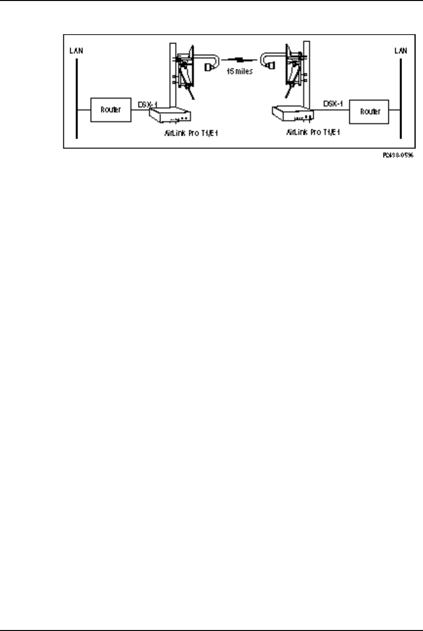
AirLink Pro T1/E1 Rack Mount Installer’s Guide
Configuration
Rev. B - 1/97
3-12
Figure 3-1
Point-to-Point Link
Hub Application (Different Paths) (Applications 1, 2, and 8)
In a hub, where more than one AirLink Pro T1/E1 Rack Mount master unit is
located at a central site (Figure 3-2), one of the master units must be configured
as the primary master at the hub (application 1), providing burst
synchronization, while a second unit is selected as the backup hub master
(application 8). All other units at the hub are designated as secondary masters
at the hub (application 2).
The primary master supplies burst sync as long as it is operating properly.
Should the primary fail, the backup master will provide burst sync to all other
secondary masters. The externally timed secondary masters are daisy-chained
through their burst synchronization wire pairs to the internally timed primary
master so that all of the units “talk” and “listen” in a synchronized manner
(Refer to Chapter 2, Figure 2-12).
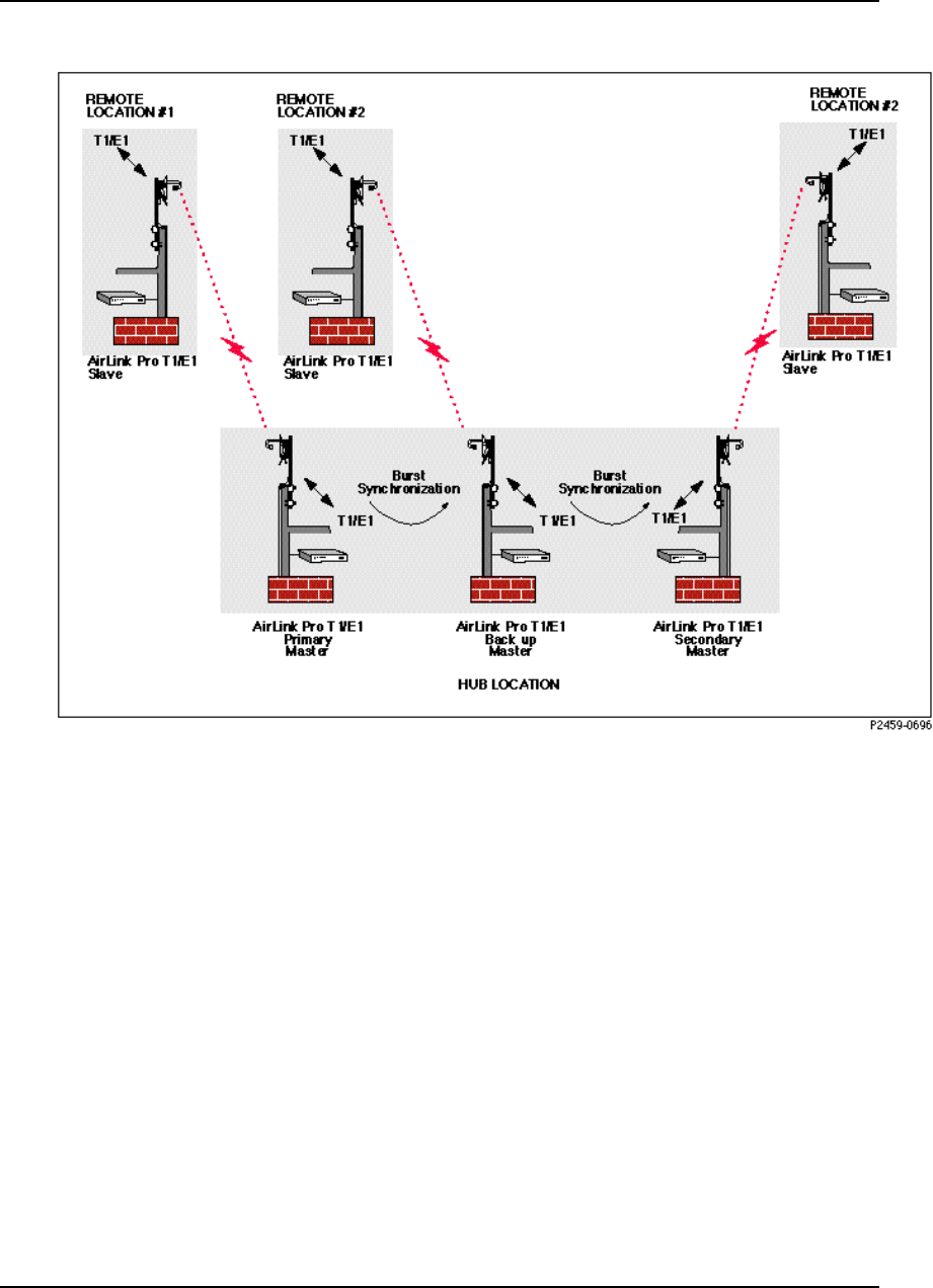
AirLink Pro T1/E1 Rack Mount Installer’s Guide
Configuration
Rev. B - 1/97
3-13
Figure 3-2
Hub Application Different paths
Hub Application (Same Path) (Application 7)
This example involves the use of antenna pairs configured to take advantage of
fixed horizontal and vertical wave polarization. Wave polarization is
achieved by mounting the antenna pair so that the feedhorns of both antennas
are aligned either vertically or horizontally (per manufacturer’s instructions).
By using antenna polarization, you can locate two AirLink Pro T1/E1 Rack
Mount pairs at the same sites and use the same wave path without conflict (see
Figure 3-3). In this application, the primary master provides burst sync to the
secondary master and the two units are connected to a AirLink Pro T1/E1 Rack
Mount protection switch (Application 7).
When the Primary master fails, the link does not break because the secondary
master transfers to its own internal burst sync.
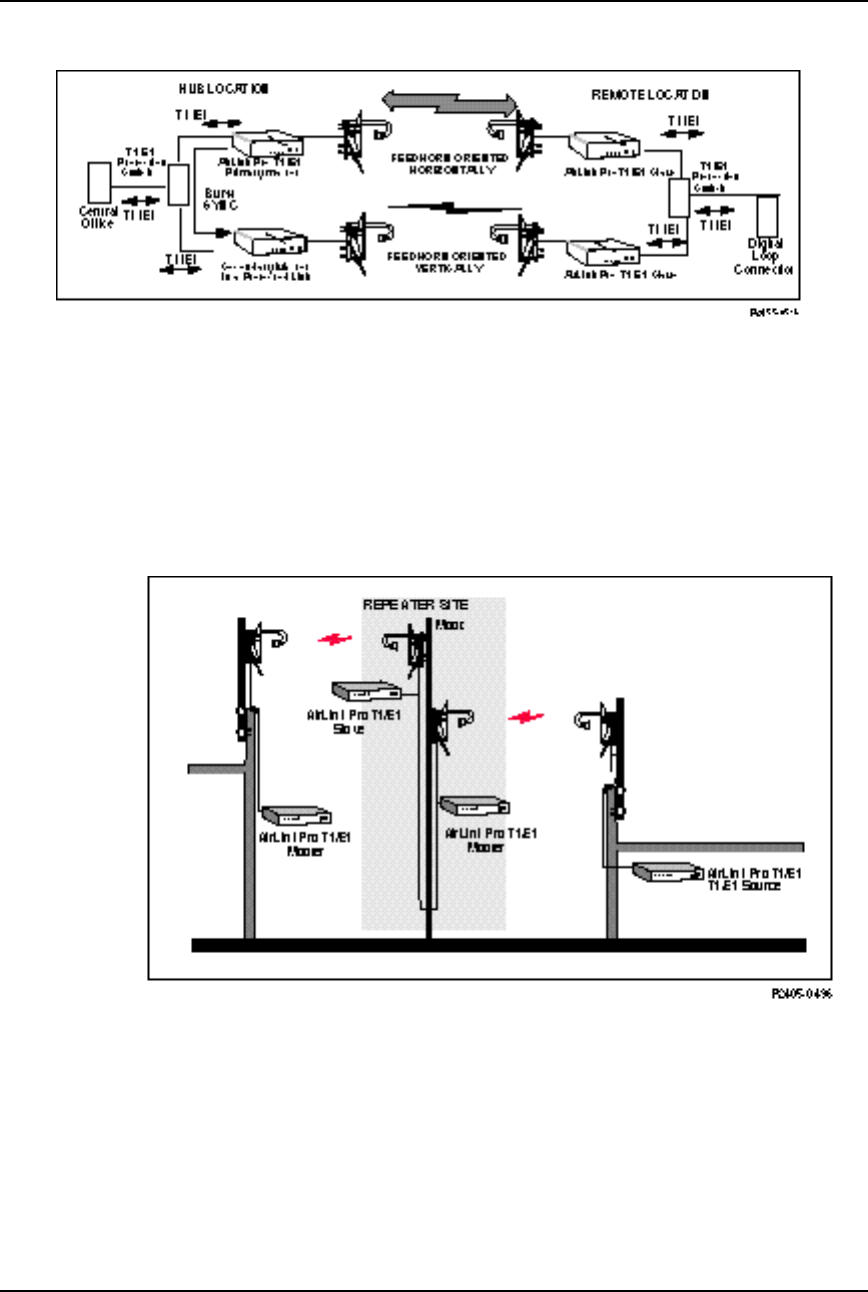
AirLink Pro T1/E1 Rack Mount Installer’s Guide
Configuration
Rev. B - 1/97
3-14
Figure 3-3
Hub Application Same Path
Repeater (Applications 3 and 5)
In a repeater, the two AirLink Pro T1/E1 Rack Mount units that form the cross-
over point between the previous segment of the entire repeater link and the next
segment of the repeater link are referred to as the repeater site (Figure 3-4).
Figure 3-4
AirLink Pro T1/E1 Rack Mount Two Part Repeater Link
In this case, the slave unit of the previous segment of the repeater link is
configured as the slave unit at a repeater site (application 5), while the master
unit of the next segment of the repeater link is configured as the master unit at a
repeater site (application 3). The burst synchronization signal pair of the
slave unit at the repeater site is wired to the burst synchronization signal pair

AirLink Pro T1/E1 Rack Mount Installer’s Guide
Configuration
Rev. B - 1/97
3-15
of the master unit at the repeater site so that the slave at the repeater site
provides the burst synchronization signal for the master unit of the next
segment of the link.
Repeater Variations
If other AirLink Pro T1/E1 Rack Mount units are located at the repeater site,
the repeater site is treated as a hybrid hub, where the added units are wired to
the burst synchronization signal pairs of the slave at the repeater site and
synchronize their transmit bursts to the burst synchronization signal from the
slave at the repeater site. These units can be configured as either secondary
masters at a hub (application 2) or as master units at a repeater site
(application 5).
If the entire repeater link is set up as a point-to-point link, the AirLink Pro
T1/E1 Rack Mount unit that serves as the near-end unit in the entire repeater
link can be configured as a master unit in a point-to-point link (application 4).
The AirLink Pro T1 unit that serves as the far-end unit for the entire repeater
link is configured as a slave unit in a point-to-point link (application 6).
If the entire repeater link originates from a hub, the AirLink Pro T1/E1 Rack
Mount unit that serves as the near-end unit in the entire repeater link can be
configured as either a primary master at a hub (application 1) or a secondary
master at a hub (application 2). The AirLink Pro T1/E1 Rack Mount unit that
serves as the far-end unit for the entire repeater link is configured as a slave
unit in a point-to-point link (application 6).
Burst Mode
Burst Mode describes the transmit timing relationship between the master unit
and the slave unit. In Normal mode, the master unit initiates burst timing and
the slave unit times its responses to the timing from the master. The master unit
transmits for a time, then listens for a time; the slave waits until the master
unit is listening, then transmits. In Test mode, the master transmits a constant
RF using the QRSS data pattern; the slave only listens.
NOTE Test mode should only be used for alignment and testing under the direction of Cylink
personnel. In ordinary operation, the unit should be set for Normal operation.
To set the burst mode for the local AirLink Pro T1/E1 Rack Mount, type the
following command at the AirLink Pro T1/E1 Rack Mount prompt:
AIRLINK PRO T1/E1> set burst mode operand

AirLink Pro T1/E1 Rack Mount Installer’s Guide
Configuration
Rev. B - 1/97
3-16
where operand is either Normal or Test. If you do not specify a value, the
system assumes the default value: Normal.
For example, to set the burst mode for the local AirLink Pro T1 to Normal, type
the following command at the AirLink Pro T1/E1 Rack Mount prompt:
AIRLINK PRO T1/E1> set burst mode normal
To set the burst mode of the remote AirLink Pro T1, use the command:
AIRLINK PRO T1/E1> remote set burst mode operand
WARNING If the burst mode of the remote unit is changed from Normal to Test, it cannot be
restored to Normal from the local unit.
PN Code
The AirLink Pro T1/E1 Rack Mount has a set of pseudo-random noise (PN)
codes. Each code number corresponds to a subset of long binary code words. These
code words are substituted for each bit in the T1 data stream. This substitution
is the basic principle of the direct-sequence spread spectrum modulation
scheme used in the AirLink Pro T1/E1 Rack Mount.
No PN code is “better” or “worse” than another. Using a different code
separates the AirLink Pro T1/E1 Rack Mount and the desired incoming signal
from undesired signals from other AirLink Pro T1/E1 Rack Mount paths.
The master unit and the slave unit of a AirLink Pro T1/E1 Rack Mount pair must
be set to the same PN code (pseudo-random noise code). The setting is then
stored in the protected system configuration memory of both units in the pair.
To set the PN code for the local unit, type the following command at the
AirLink Pro T1/E1 Rack Mount prompt:
AIRLINK PRO T1/E1> set pn code operand
where operand is a number from 1 to 8. If you do not specify a value, the system
assumes the default value: 1. For example, to set the PN code for the local
AirLink Pro T1 to 4, type the following command at the AirLink Pro T1 prompt:
AIRLINK PRO T1/E1> set pn code 4

AirLink Pro T1/E1 Rack Mount Installer’s Guide
Configuration
Rev. B - 1/97
3-17
To set the PN code of the remote unit, use the command:
AIRLINK PRO T1/E1> remote set pn code operand
RF Power Level
When there are a number of AirLink Pro T1/E1 Rack Mount pairs in a hub
arrangement, the received signal levels are dependent on the distances to the
remote sites. Adjust the transmit power level to minimize cross-channel
interference and ensure that the received levels at the hub are of equal power.
To set the RF power for the local AirLink Pro T1/E1 Rack Mount, type the
following command at the AirLink Pro T1/E1 Rack Mount prompt:
AIRLINK PRO T1/E1> set rf power operand
where operand is a number from -4 to 20.
If you do not specify a value, the system assumes the default value: 0 (dBm).
For example, to set the RF power level for the local AirLink Pro T1/E1 Rack
Mount to -1, type the following command at the AirLink Pro T1/E1 Rack Mount
prompt:
AIRLINK PRO T1/E1> set rf power -1
To set the RF power for the remote unit, type the following command at the
AirLink Pro T1/E1 Rack Mount prompt:
AIRLINK PRO T1/E1> remote set rf power operand
Order Wire Type
The type of order wire interface (2 or 4) is selected from the command line
interface configuration screen. The interface must be the same at both ends of
the link.
To set the order wire interface for the local unit, type:
AIRLINK PRO T1/E1> Set orderwire 2W
To set the order wire for the remote unit, type the following command at the
AirLink Pro T1/E1 Rack Mount prompt:
AIRLINK PRO T1/E1> remote set orderwire 2W

AirLink Pro T1/E1 Rack Mount Installer’s Guide
Configuration
Rev. B - 1/97
3-18
Interface Type (E1 Only)
Set the interface operand on the E1, where the operand is balanced or
unbalanced.
Setting Alarm Control Parameters
The alarm control parameters of the AirLink Pro T1/E1 Rack Mount include:
❚Alarm reporting
❚Alarm level
❚1-hour Errored Seconds (ES) threshold
❚1-hour Unavailable Seconds (UAS) threshold
❚24-hour ES threshold
❚24-hour UAS threshold
❚Receive (Rx) power
❚Transmit (Tx) power
The following sections describe how to set values for these parameters.
Alarm Reporting
This parameter determines whether alarms are displayed as they happen or
are held until you query for them. When an alarm event occurs, an alarm
message is inserted in the event queue and the Major or Minor indicator is
illuminated and the alarm relay contacts are de-energized: the NO contact is
closed; the NC contact is opened.
The Major Alarm LED is red and indicates that there is one or more of the
following events has occurred: transmit power below threshold, synthesizer
loss of lock, transmitter failure, DTE input loss, radio sync loss, loss of primary
burst sync (single sync bus), loss of primary and backup burst sync (dual sync bus).
The minor Alarm LED is yellow and indicates that one or more of the following
events has occurred: rcv input level below threshold, unit has been placed in a
test mode, ES threshold exceeded, UAS threshold exceeded, loss of primary or
backup burst sync (dual sync mode).

AirLink Pro T1/E1 Rack Mount Installer’s Guide
Configuration
Rev. B - 1/97
3-19
To set the alarm reporting priority for the local unit, type the following
command at the AirLink Pro T1/E1 Rack Mount prompt:
AIRLINK PRO T1/E1> set alarm reporting operand
where operand is either Request or Immediate. If you do not specify a value,
the system assumes the default value: Immediate. For example, to set the
alarm reporting priority for the local unit to Request, type the following
command at the AirLink Pro T1 prompt:
AIRLINK PRO T1/E1> set alarm reporting request
To set the alarm reporting priority of the remote unit, type:
AIRLINK PRO T1/E1> remote set alarm reporting operand
Alarm Level
The alarm level parameter sets the severity level for reporting alarms: Status,
Advisory, Alarm, and Fault. The status messages are the least severe; fault
messages the most severe.
If you set the alarm level at Status, the system reports all four levels. If you set
the alarm level at Fault, the system only reports fault events (refer to
Appendix A for alarm messages).
To set the alarm level for the local unit, type the following command at the
AirLink Pro T1/ E1 Rack Mount prompt:
AIRLINK PRO T1/E1> set alarm level operand
where operand is one of the following: Status, Advisory, Alarm or Fault. If
you do not specify a value, the system assumes the default value: Status.
For example, to set the alarm level for the local unit to Alarm, type the
following command at the AirLink Pro T1/E1 Rack Mount prompt:
AIRLINK PRO T1/E1> set alarm level Alarm
To set the alarm level of the remote AirLink Pro T1/E1 Rack Mount, type:
AIRLINK PRO T1/E1> remote set alarm level operand

AirLink Pro T1/E1 Rack Mount Installer’s Guide
Configuration
Rev. B - 1/97
3-20
1-Hour Errored Seconds Threshold
This parameter sets the number of errored seconds (ES) events that must occur in
a one-hour interval before an entry is inserted in the Alarm queue. The 1-hour
ES threshold is compared to the number of errored seconds in the past hour. If
the 1-hour ES count is greater than the threshold value, the unit inserts a
message in the alarm log.
To set the 1-hour ES threshold for the local radio unit, type the following
command at the AirLink Pro T1/E1 Rack Mount prompt:
AIRLINK PRO T1/E1> set threshold 1_hr es operand
where operand is a number from 1 to 999. If you do not specify a value, the
system assumes the default value: 1. For example, to set the 1-hour ES
threshold for the local unit to 15, type the following command at the AirLink
Pro T1/E1 Rack Mount prompt:
AIRLINK PRO T1/E1> set threshold 1_hr es 15
To set the 1-hour ES threshold of the remote unit, type:
AIRLINK PRO T1/E1> remote set threshold 1_hr es operand
1-Hour Unavailable Seconds Threshold
This parameter sets the number of unavailable seconds (UAS) events that must
occur in a one-hour interval before an entry is inserted in the Alarm queue. The
1-hour UAS threshold is compared to the number of unavailable seconds in the
past hour. If the 1-hour UAS count is greater than the threshold value, the unit
inserts a message in the alarm log.
To set the 1-hour UAS threshold for the local radio unit, type the following
command at the AirLink Pro T1/E1 Rack Mount prompt:
AIRLINK PRO T1/E1> set threshold 1_hr uas operand
where operand is a number from 1 to 99. If you do not specify a value, the system
assumes the default value: 1. For example, to set the local unit’s 1-hour UAS
threshold to 15, type the following command at the AirLink Pro T1/E1 Rack
Mount prompt:
AIRLINK PRO T1/E1> set threshold 1_hr uas 15
To set the 1-hour UAS threshold of the remote unit, use the command:

AirLink Pro T1/E1 Rack Mount Installer’s Guide
Configuration
Rev. B - 1/97
3-21
AIRLINK PRO T1/E1> remote set threshold 1_hr uas operand
24-Hour Errored Seconds Threshold
This parameter sets the number of errored seconds (ES) events that must occur in
a 24-hour interval before an entry is inserted in the Alarm queue. The 24-hour
ES threshold is compared to the number of errored seconds in the past 24 hours.
If the 24-hour ES count is greater than the threshold value, the unit inserts a
message in the alarm log.
To set the 24-hour ES threshold for the local unit, type the following command
at the AirLink Pro T1/E1 Rack Mount prompt:
AIRLINK PRO T1/E1> set threshold 24_hr es operand
where operand is a number from 1 to 999. If you do not specify a value, the
system assumes the default value: 1. For example, to set the 24-hour ES
threshold for the local radio unit to 15, type the following command at the
AirLink Pro T1/E1 Rack Mount prompt:
AIRLINK PRO T1/E1> set threshold 24_hr es 15
To set the 24-hour ES threshold of the remote unit, use the command:
AIRLINK PRO T1/E1> remote set threshold 24_hr es operand
24-Hour Unavailable Seconds Threshold
This parameter sets the number of unavailable seconds (UAS) events that must
occur in a 24-hour interval before an entry is inserted in the Alarm queue. The
24-hour UAS threshold is compared to the number of unavailable seconds in the
past 24 hours. If the 24-hour UAS count is greater than the threshold value, the
unit inserts a message in the alarm log.
To set the 24-hour UAS threshold for the local unit, type the following
command at the AirLink Pro T1/E1 Rack Mount prompt:
AIRLINK PRO T1/E1> set threshold 24_hr uas operand
where operand is a number from 1 to 99. If you do not specify a value, the system
assumes the default value: 1. For example, to set the local unit’s 24-hour UAS
threshold to 15, type the following command at the AirLink Pro T1/E1 Rack
Mount prompt:
AIRLINK PRO T1/E1> set threshold 24_hr uas 15

AirLink Pro T1/E1 Rack Mount Installer’s Guide
Configuration
Rev. B - 1/97
3-22
To set the 24-hour UAS threshold of the remote unit, use the command:
AIRLINK PRO T1/E1> remote set threshold 24_hr uas operand
Receive (Rx) PowerThreshold
This parameter sets the minimum receive power level before an entry is
inserted in the event queue. This threshold should be set approximately 10 dB
below the receive power level to allow for occasional fading.
To set the Rx power threshold for the local unit, type the following command at
the AirLink Pro T1/E1 Rack Mount prompt:
AIRLINK PRO T1/E1> set threshold rx power operand
where operand is a number from -80 to -40 (dBm). If you do not specify a value,
the system assumes the default value: -75. For example, to set the Rx power
threshold for the local unit to -45 dBm, type the following command at the
AirLink Pro T1/E1 Rack Mount prompt:
AIRLINK PRO T1/E1> set threshold rx power -45
To set the Rx power threshold of the remote unit, use the command:
AIRLINK PRO T1/E1> remote set threshold rx power operand
Transmit (Tx) Power Threshold
This parameter sets the minimum transmit power level before an entry is
inserted in the event queue. This threshold should be set approximately 6 dB
below the transmit power level.
To set the Tx power threshold for the local unit, type the following command at
the AirLink Pro T1/E1 Rack Mount prompt:
AIRLINK PRO T1/E1> set threshold tx power operand
where operand is a number from -10 to 20 (dBm). If you do not specify a value,
the system assumes the default value: -6 (dBm). For example, to set the Tx
power threshold for the local AirLink Pro T1 to 10 dBm, type the following
command at the AirLink Pro T1/E1 Rack Mount prompt:
AIRLINK PRO T1/E1> set threshold tx power 10
To set the Tx power threshold of the remote radio unit, use the command:

AirLink Pro T1/E1 Rack Mount Installer’s Guide
Configuration
Rev. B - 1/97
3-23
AIRLINK PRO T1/E1> remote set threshold tx power operand
Setting Modem Parameters
Introduction
TheAirLink Pro T1/E1 Rack Mount ASCII terminal and Network Management
ports are EIA/TIA-232 interfaces that allow terminal devices or personal
computers to control and monitor AirLink Pro T1/E1 Rack Mount operation at
either end of a point-to-point link. Each EIA/TIA-232 connection can be either
a direct connection (device to port), or an indirect connection (device to modem to
port) for dial-up operation.
The Network Management (Modem) Port is available only on the Access Unit,
and uses a different physical port from the Terminal port. However, when the
network management port is connected (and dialed-up, in the case of a modem
link), commands issued from that port, along with the responses from the
terminal port, are duplicated at the Network Management port.
The modem support may be configured to work in any of these five modes:
DISABLED The port is completely disabled and it will not
respond to user commands or connection
indications from the modem.
DEDICATED The port behaves exactly as the Terminal
port; all commands and responses taking place
on that port are duplicated on the modem port.
ANSWER The modem port remains idle (does not respond
to user commands) until it receives a dial-in
indication from the modem.
DIALOUT ONLY The modem port is used only for dialing-out to
report alarms.
DIALOUT/ANSWER Combines the functionality of the ANSWER
and DIAL-OUT modes.
After the completion of a dial-out, a connection announcement is printed at the
remote end. This announcement identifies the unit type, the site name as
configured by the user, the date and time, plus a copy of the alarm text message.

AirLink Pro T1/E1 Rack Mount Installer’s Guide
Configuration
Rev. B - 1/97
3-24
For example:
>>> AIRLINK-T1> Sunnyvale Engineering Unit 1
12 APR 95 14:33:59 Receive Power Below Threshold
NOTE The particular alarm message chosen is the highest-priority alarm condition in effect when
dialing commences.
Connection and Configuration
The unit is shipped with a default configuration of DISABLED and 9600 bps.
Any changes to the default values can be made using the command line
interface. To change the settings, use the command line interface. Each of the
configuration items is stored in the configuration database. In addition, the
state of the connection is maintained so that recovery from a power failure will
re-initiate the connection.
Multidrop configuration (multiple units sharing a modem) is supported only by
the use of an external port-sharing device.
Modem Setup Procedures
A pair of Hayes-compatible “external” modems, 1200 bps or higher is required.
Configure each modem according to the following procedure. Note that not all
so-called smart modems are identical. Please check your modem user’s manual.
Configuring the Modem
1. To reset modem to its factory defaults (for most modems):
a. Connect the modem to a terminal using a standard EIA/TIA-232 modem
cable.
b. Wait one second then type +++ on the terminal. Pause one second again
and then type AT&F<RETURN>.
c. Cycle power on the modem.
2. Configure the modem to ignore DTR, by typing AT&D<RETURN>, or
selecting a DIP switch on some modems.
3. Configure the modem to ignore RTS, by typing AT&K0<RETURN> (Hayes
compatible modems), or AT&H0<RETURN> (US Robotics modems), or by
selecting a DIP switch on some modems.

AirLink Pro T1/E1 Rack Mount Installer’s Guide
Configuration
Rev. B - 1/97
3-25
4. Configure the modem for error correction, if the modem is so equipped
(newer modems). This is generally the factory default, but can be invoked
by typing AT&Q5<RETURN> on Hayes compatible modems, or
AT&M4<RETURN> on US Robotics modems.
5. Set the number of rings you want the modem to answer on, by typing
ATS0=X<RETURN> where x is a digit from 1 to 9 (the number of rings), or
0 (zero) for no answer.
6. Save the new configuration in the modem’s non-volatile memory by typing
AT&W<RETURN>.
7. Cycle power on the modem.
Connecting the Modem
Connect the modem at the AirLink Pro T1/E1 Rack Mount end as follows:
1. Configure the AirLink Pro T1/E1 modem port speed by issuing the
following command at the Terminal port SET MODEM RATE XXXX
<RETURN> where XXXX is the speed in bits per second, for instance 1200,
2400, 4800, or 9600.
2. Connect the unit’s modem port to the modem using a standard EIA/TIA-232
modem cable, with a 9-pin male DB-9 connector at the unit end and an
appropriate connector (typically male DB-25) at the modem end.
3. Connect the modem’s phone port to the phone line using an appropriate
cable (usually supplied with the modem).
Connecting the Modem to the Remote Terminal
Connect the modem to the remote terminal as follows:
1. Connect the terminal’s modem port to the modem using a standard
EIA/TIA-232 modem cable.
2. Connect the modem’s phone port to the phone line using an appropriate
cable (usually supplied with the modem).

AirLink Pro T1/E1 Rack Mount Installer’s Guide
Configuration
Rev. B - 1/97
3-26
Testing the Modem Link
1. Issue the following commands at the Terminal port:
Table 3-2
Terminal Commands of the Modem (Port) Interface
Command Definition
SET DIAL LEVEL FAULT <RETURN> Prevents dialing of most alarms while the link
testing
SET ALARM HOLDOFF 600 <RETURN> Prevents any alarms from being dialed for at least
10 minutes
SET MODEM MODE BOTH <RETURN> Enables dial-in and dial-out
SET DIAL TONE <RETURN> TONE (touch-tone) or PULSE (rotary)
SET PHONE 1 XXX-XXXX <RETURN> XXX-XXXX is the remote modem phone number
SET PHONE 2 XXX-XXXX <RETURN> Optional backup phone number
GET MODEM <RETURN> To view and verify the modem configuration
CONNECT 1 Manually dial the phone number programmed by
the SET PHONE 1 command above
2. Type characters at the terminal port; they should appear on the terminal
connected to the remote modem. Type characters at the remote terminal.
They should appear on the local terminal.
3. Type DISCONNECT <RETURN> on the unit’s terminal to terminate the
manual dial-out connection. The modem link is now operational.
Functions
Port Duplication
During a manual connection (dial-in or dial-out), the modem and Command Line
Interface (CLI) ports appear as one at the character level. Any character typed
by either party is echoed on both terminals and entered into the ensuing
command. For example, if the CLI port user types "GET" and the modem port
user types "<blank>CONFIG" and presses RETURN, both users will see "GET
CONFIG" and the GET CONFIG screen.

AirLink Pro T1/E1 Rack Mount Installer’s Guide
Configuration
Rev. B - 1/97
3-27
Login
When first dialing in, the remote user is not required to enter a password if the
local user is already logged in.
Auto Answer Function
If Auto Answer mode is selected, the unit sends an automatic answering
command to the modem to answer incoming calls after a designated number of
rings. Otherwise, the modem will be configured not to answer.
Events
Events are defined in the AirLink Pro T1/E1 Rack Mount as Faults, Alarms,
Advisories, or Status Messages. These are the four levels of severity, with
Faults being the highest. The user may select a dial-out threshold as one of
these levels by issuing the SET DIAL LEVEL command, in much the same way
as selecting the event reporting level with the SET ALARM LEVEL command.
The Dial-out function will dial out when there is a condition at or above that
level. For proper operation, the dial-out severity level must be equal to or
greater than the event queuing level.
Dialout Function
During an event, the modem is directed to dial the telephone number(s) in the
configuration database and send a brief descriptive announcement. The
connection is then terminated. Up to two numbers can be selected; a primary
number that will always be dialed first, and a backup number in case the unit
cannot reach the primary number. Also, the unit will make repeated attempts
to dial if the first attempt is unsuccessful.
Operation
There are two user-configurable thresholds for alarms. An alarm threshold
establishes the point when the unit begins to dial-out. In addition, to prevent
excessive dialing in the presence of repetitive events, a dial holdoff time is
defined.
Alarm Holdoff Time (0 - 600 seconds; default = 10)
One or more events must persist between 0 - 600 seconds before a dial-out
attempt is made. When set to zero, the unit dials out immediately.
One qualifying event must be present although Alarm Holdoff does not require
the same condition for the entire interval.

AirLink Pro T1/E1 Rack Mount Installer’s Guide
Configuration
Rev. B - 1/97
3-28
Repeat Alarm Count (2 - 1000 counts; default = 10)
Events are alternately declared and cleared for cyclical alarm conditions and
must be declared between 2 - 1000 counts during the period defined by Alarm
Holdoff Time. The event does not have to be the same one each time. Dial-out
is not attempted until the end of the alarm holdoff time, even if the Repeat
Count is reached before then.
Dial Holdoff Time (0 - 5000 minutes; default = 10)
Dial Holdoff Time is the length of time to wait between successive dial-outs
when alarms are repetitive. This alarm timer operates independently of the
alarm holdoff time and repeat alarm count. After a dial-out, any persistent or
repeated alarm conditions will wait until the end of the dial holdoff time.
When the interval value is set to zero, there will be a minimum 10 seconds
between the last time the local modem hung up and the next attempt (in
conformance with EIA-602).
Dial Holdoff does not apply in the case of failure to connect; instead, the Dial
Retry time is applied.
If any of the above parameters is changed, or if the event queue is reset with
the RESET ALARMS command, the holdoff counters and timers will be
reinitialized. This is to prevent spurious dial-outs.
Repeat Dialing and Prioritization
During dial-out, an alarm text message is sent according to a prioritization
scheme (the highest-severity alarm condition in effect is sent first). If there
are multiple alarms present at that level, the text is for the first-occurring
event.
Although Radio Sync Loss and Receive Power Below Threshold are both at the
level of ALARM, Radio Sync Loss takes priority over Receive Power Below
Threshold, for dial-out purposes. (Both are at the ALARM level for SET
ALARM THRESHOLD and SET DIAL THRESHOLD.)
Alarm conditions of a persistent nature, that do not clear themselves, will
result in repeated dial-outs. Alarms of this class include all the conditions at
the ALARM and FAULT levels, such as Radio Sync Loss and Receive Signal
Level Below Threshold. One-time events, such as Errored-second threshold
exceeded, and fault-cleared conditions, result in only a single dial-out.

AirLink Pro T1/E1 Rack Mount Installer’s Guide
Configuration
Rev. B - 1/97
3-29
Telephone Numbers and Dial Format
The primary telephone number is the first number dialed. Ringing will continue
for a user-specified period (default is 30 seconds) before giving up as
unanswered. When the connection to the primary telephone number is not
successful, then the secondary number is attempted.
If neither the primary nor the secondary number is successful, then the AirLink-
T1 waits for a Dial Retry period before retrying. In this case, an advisory event
is logged stating the reason for the failed dial-out. In addition, if the unit is
unable to communicate with the modem, it will continuously retry (no holdoff
period is imposed), and log an advisory. Only one advisory message of each
type will be logged per dialing session (from the first failed attempt until dial-
out is successful) in order to prevent the event queue from becoming flooded with
dial-out failures. No busy or no-answer advisory event will cause a dial-out.
The telephone numbers are entered as 40 characters, including the "ATDT"
prefix. If there is no primary number, the secondary number is never attempted.
The following characters may be used in the telephone number fields:
0-9 Dial numbers
, (comma) Pause 1 second each before processing next char
(to wait for second dial tone after dialing '9')
!Flash (0.5 second ON-HOOK signal)
@causes the modem to wait 30 seconds for one or more rings
followed by 5 seconds of silence before processing the next
character. This is used when the system being called does not
provide a dial tone.
# # key on touch-tone telephone keypad
** key on touch-tone telephone keypad
- (dash) No meaning; provided for user convenience
( ) No meaning; provided for user convenience
' ' Blank spaces are ignored.
User-Directed Connections
To troubleshoot, enter the command to dial a specific telephone number and
hold the connection. The syntax for this command is:
CONNECT 1
CONNECT 2

AirLink Pro T1/E1 Rack Mount Installer’s Guide
Configuration
Rev. B - 1/97
3-30
CONNECT telephone-number
When the parameter is given as 1 or 2, the unit will dial the stored primary or
backup phone number respectively. Otherwise, the modem will dial the
number supplied on the command line. The telephone number must follow the
syntax of the configured telephone numbers.
CONNECT does not automatically retry upon dial-out failure; this is strictly a
manual operation. To redial, use the control-R key to repeat the last command.
When this command is used, the connection remains in effect until the user
issues a DISCONNECT command, the remote modem hangs up, or (if
configured), a Connection Timeout timer expires.
Manual or automatic connections can be terminated immediately by using the
following command:
DISCONNECT
This immediately hangs up the telephone connection and returns the dial-out
function to IDLE. RTS is returned to its configured state and DTR is released.
DISCONNECT also abandons any dial-out attempt in progress but does NOT
prevent future dial-outs. For this reason, the mode should be set to DISABLED
before performing any maintenance functions.
RS-232 Modem Port Interface
Data Rate and Port Parameters
The Data Rate is part of the port configuration. The available rates are 1200,
2400, 4800, and 9600 bits per second.
So-called "smart modems" of the type commonly in use, "auto-baud" or adjust
their RS-232 bit rate to that of the DTE.
Before using an unknown modem, it is a good idea to reset its configuration to the
factory defaults, then configure the three-wire operation if desired. For most
modems, this can be accomplished by issuing the following commands:
AT&F<RETURN> Reset to factory defaults
AT&K0<RETURN> Ignore RTS
AT&D0<RETURN> Ignore DTR
The remaining unchanging port parameters are:
1 start bit
1 stop bit

AirLink Pro T1/E1 Rack Mount Installer’s Guide
Configuration
Rev. B - 1/97
3-31
8 data bits
no parity
Protocol Modems
Protocol modems support MNP or other data compression. Since protocol
modems introduce unneeded complications for flow control, and the AirLink Pro
T1/E1 Rack Mount modem data rate needs are modest, such protocols should be
turned off. However, error correction should be enabled if available; it will
prevent garbage characters from appearing on the remote terminal when the
unit hangs up the modem. This option is normally enabled by factory default on
modems equipped with it.
RTS Control
RTS Control allows the Request-To-Send (RTS) line to be set to Continuous or
Switched. When set to Continuous, the RTS is asserted at all times. When set
to Switched, the RTS line is asserted.
The unit will wait a reasonable time (so the unit does not hang) for the modem
to release the CTS line before reasserting the RTS line to begin any future
transmit cycles. The Switched mode is used with modem sharing devices.
When the DTR line is needed for modem sharing devices, it can be configured to
perform the modem enable function. If the DTR line is configured for a modem
sharing device, it will perform the same as the RTS line and the response will
come from the CTS line.
Responses
All numeric responses are followed by <CR> (ASCII 13 decimal). All “word”
responses are followed by <CR> and <LF> (ASCII 10 decimal).

AirLink Pro T1/E1 Rack Mount Installer’s Guide
Configuration
Rev. B - 1/97
3-32
Table 3-3
Modem Response Definitions
Modem Response Definition
0 (zero) Numeric version of "OK"
OK Successful execution of non-dial command
CONNECT [XXXX] carrier detected; XXXX = numeric bit rate
RING Ringing detected
NO CARRIER No connection established, or connection lost
ERROR Error in command line
NO DIALTONE No dial tone present
BUSY Busy signal
NO ANSWER 5 seconds of silence not detected if '@' dial modifier was used.

AirLink Pro T1/E1 Rack Mount Installer’s Guide
Configuration
Rev. B - 1/97
3-33
User Interface Additions
Table 3-4
Modem Commands
Parameter Specification
SET ALARM HOLDOFF 0-600 (seconds)
SET ANSWER TIMEOUT 0-99 (seconds)
SET CONNECTION TIMEOUT 0 - 43200 (seconds; 0 means no time-out)
SET DIAL {TONE | PULSE}
SET DIAL HOLDOFF 0-5000 (minutes, repeat dial holdoff)
SET DIAL LEVEL {FAULT | ALARM | ADVISORY | STATUS}
SET DIAL RETRY 15-3600 (seconds)
SET MODEM MODE {DISABLED | DEDICATED DIAL_OUT | ANSWER | BOTH}
SET MODEM RATE {1200 | 2400 | 4800 | 9600}
SET MODEM RTS {SWITCHED | CONTINUOUS}
SET MODEM CTS {OBEY | IGNORE}
SET MODEM DTR {SWITCHED | CONTINUOUS}
SET MODEM VOLUME {OFF | LOW | MEDIUM | HIGH}
SET MODEM XOFF {OBEY | IGNORE}
SET PHONE 1 (XXX) XXX-XXXX
SET PHONE 2 (XXX) XXX-XXXX
SET REPEAT COUNT 0-99
SET RINGCOUNT 0-9
The GET MODEM command retrieves all of the Modem Command parameters.
This command produces a screen displaying all of the settings, the dial-out
status, and the date and time. In addition, all the SET and GET commands are
available via the REMOTE prefix.
The following commands are also supported:
CONNECT 1 manual connect
CONNECT 2 manual connect
CONNECT telephone-number manual connect
DISCONNECT manual disconnect

AirLink Pro T1/E1 Rack Mount Installer’s Guide
Configuration
Rev. B - 1/97
3-34
GET MODEM view modem and dial-out parameters
QUERY RS232 status of RS-232 handshaking lines
Responses and Alerts
Each of the following messages is an advisory. These advisories will not
trigger a dial-out, but they are entered into the Event Queue.
"Modem Busy"
"No Modem"
"No Answer"
"No Dialtone"
Default Parameters
Table 3-5
AirLink Pro T1/E1 Rack Mount Dialout Parameters
Parameter Default
ALARM HOLDOFF 10 seconds
ANSWER TIMEOUT 30 seconds
CONNECTION TIMEOUT 3600 seconds (1 hour)
DIAL FORMAT TONE
DIAL HOLDOFF 10 minutes
DIAL LEVEL ALARM
MODEM MODE DISABLED
MODEM RATE 9600
MODEM RTS CONTINUOUS
MODEM CTS IGNORE
MODEM DTR CONTINUOUS
MODEM VOLUME LOW
MODEM XOFF IGNORE
PHONE 1 (blank)
PHONE 2 (blank)
REPEAT COUNT 10 events
RINGCOUNT 1

AirLink Pro T1/E1 Rack Mount Installer’s Guide
Configuration
Rev. B - 1/97
3-35
Alarm Holdoff
This is the period of time between the onset of the first alarm condition, and
the unit dialing out to report the alarm. During this period, an alarm condition
must have existed continuously, or a minimum number of events must have
occurred. The minimum number of events is defined by Repeat Count. The alarm
events must be all be at or above the severity level, as defined by Dial Level.
To set this value, type the command:
SET ALARM HOLDOFF XXX <RETURN>
where XXX is the time period in (0 - 600) seconds. The default is 10.
Repeat Count
The number of alarm events occurring at or above the Dial Level, during the
Alarm Holdoff period, before an Alarm Dialout is initiated.
To set this value, type the command:
SET REPEAT COUNT XX <RETURN>
where XX is the number of (2 - 1000) events. The default is 10.
Dial Level
The severity level that alarm events must be to contribute to an Alarm Dialout.
To set this level, type the command:
SET DIAL LEVEL {FAULT | ALARM | ADVISORY | STATUS} <RETURN>
The default level is ALARM.
Dial Holdoff
The period of time between alarm dial-outs. This time period is independent of
the alarm holdoff and dial retry time periods. To set this value, type the
command:
SET DIAL HOLDOFF XXX <RETURN>
where XXX is the period in (1 - 5000) minutes. The default is 1.
Dial Format
To set the Dial format to TONE or PULSE, type:
SET DIAL TONE <RETURN>

AirLink Pro T1/E1 Rack Mount Installer’s Guide
Configuration
Rev. B - 1/97
3-36
or
SET DIAL PULSE <RETURN>
The default setting is TONE.
Dial Retry
If the unit dials an alarm and reaches a busy or no answer signal, the unit will
dial a second number if one is specified. Both numbers are dialed before a
holdoff period is imposed. There is no automatic retry when the unit is
configured for manual dialing.
To set the holdoff period before the unit dials the first number again, type the
command:
SET DIAL RETRY XXX <RETURN>
where XXX is the period in (15 - 3600) seconds. The default is 60.
Modem (Enabling) Mode
This is the modem operation mode that is described in the section Using the
Network Management (Modem) Port. To set this mode, type the command:
SET MODEM MODE {DISABLED | DEDICATED | DIAL_OUT | ANSWER | BOTH}
The default is DISABLED.
Modem Rate
This is the bit rate of the modem port. To set this parameter, type the
command:
SET MODEM RATE {1200 | 2400 | 4800 | 9600}
The default is 9600.
Modem RTS Mode
This mode governs whether the modem port RTS line is permanently asserted,
or switched on only when the port is sending characters. The RTS line is not
needed for use with smart modems. To change the mode, type the following
command:
SET MODEM RTS {SWITCHED | CONTINUOUS}
The default mode is CONTINUOUS.

AirLink Pro T1/E1 Rack Mount Installer’s Guide
Configuration
Rev. B - 1/97
3-37
Modem DTR Mode
This governs whether the modem port DTR line is permanently asserted or
switched on only when the port is sending characters. The DTR line is not
needed for use with smart modems. To change the mode, type the following
command:
SET MODEM DTR {SWITCHED | CONTINUOUS}
The default mode is CONTINUOUS.
Phone Numbers 1 and 2
Phone number 1 is the phone number that the unit will dial first when trying to
send out an alarm message. The phone number must be specified if a dial-out
mode is chosen. Phone number 2 is an optional second phone number that the
unit will dial if Phone number 1 is busy or does not answer.
To set phone numbers, type the command:
SET PHONE 1 XXX-XXXX <RETURN>
or
SET PHONE 2 XXX-XXXX <RETURN>
where XXX-XXXX is the phone number. Any string of up to 20 characters is
acceptable, provided the modem can interpret it. This string is preceded by the
letters ATDT or ATDP depending on whether tone or pulse dialing is selected.
Any special dialing prefixes should precede the number entered here, such as
“9," for dialing out from a PBX, or any special sequences for disabling Call
Waiting. For example:
SET PHONE 1 9, 555-5555 <RETURN>
Ring Count
This mode determines the number of rings the modem at the unit end will
answer. In order to use this command, the modem must be connected to the unit
and preferably be on hook. To set this value, type the command:
SET RINGCOUNT X <RETURN>
where X is the number of ( 0 - 9) rings. Zero (0) means Do Not Answer. The
default is 1.

AirLink Pro T1/E1 Rack Mount Installer’s Guide
Configuration
Rev. B - 1/97
3-38
Answer Timeout
For dialing out, this is the time period after that the unit will declare a no-
answer condition, and if a second phone number is defined, attempt that number.
To set this value, type the command:
SET ANSWER TIMEOUT XX <RETURN>
where XX is the period in (0 to 99) seconds. The default is 30 seconds. This can
be adjusted depending on the number of rings that the remote modem is
programmed to answer.
Connection Timeout
This mode determines the time period the unit will terminate a manual
connection, either dial-in or dial-out. To set this value, type the command:
SET CONNECTION TIMEOUT XXXX <RETURN>
where XXXX is the time period in (0 - 43200) seconds. The default value is 3600
(one hour). A value of zero means that no time-out will be applied and the
modem link will remain connected indefinitely.
Getting AirLink Pro T1/E1 Rack Mount Configuration
Information
The GET command keyword requests configuration-related information from the
AirLink Pro T1/E1 Rack Mount. Use the REMOTE command keyword to request
configuration-related information from the far-end AirLink Pro T1/E1 Rack
Mount on the following:
❚Configuration parameter settings
❚Threshold settings
❚Hardware and software revision levels
Configuration Parameter Settings
To list the current configuration parameter settings, type the following
command at the AirLink Pro T1/E1 Rack Mount prompt:
AIRLINK PRO T1/E1> get configuration

AirLink Pro T1/E1 Rack Mount Installer’s Guide
Configuration
Rev. B - 1/97
3-39
The system displays a list of information similar to the following:
AIRLINK PRO T1/E1> get configuration
Site Name: Cylink Sunnyvale 2
Application: 1. Primary Master at a Hub
Burst Mode: Duplex
Coding: B8ZS/HDB3
Equalization: 0 - 133
PN Code: 1
RF Power: 0.0 dBm
Alarm Reporting: Immediate
Alarm Level: Status
Date/Time: jun 9 1996 10:35:00
Threshold Settings
To list the current threshold settings, type the following command at the
AirLink Pro T1/E1 Rack Mount prompt:
AIRLINK PRO T1/E1> get threshold
The system displays a similar list:
AIRLINK PRO T1/E1> get threshold
1 HR ES: 20
1 HR UAS: 5
24 HR ES: 25
24 HR UAS: 8
Rx Power: -75 dBm
Tx Power: 0 dBm
Hardware and Software Revision Levels
To list the hardware and software revision information, type the following
command at the AirLink Pro T1/E1 Rack Mount prompt:
AIRLINK PRO T1/E1> get revision
The system displays a similar list:
AIRLINK PRO T1/E1> get revision
Site Name: sunnyvale 2
Digital Assembly: 14501-010

AirLink Pro T1/E1 Rack Mount Installer’s Guide
Configuration
Rev. B - 1/97
3-40
Digital List: 1
Digital Issue: A
Digital S/N: 001
FPGA Rev: 14496-0100
Software Rev: 1.00
IF Assembly: 13559-020-03
IF List: 1
IF Issue: A
IF S/N: 001
Top Assembly: 14413-010-00
Top Assembly:S/N: 00000000
OK
Command Keywords and Operands
In addition to the SET and GET command keywords, the terminal user interface
provides command keywords that monitor status, performance, and alarms, to
initiate QRSS and loop tests, and reset alarm and test counters.
The command keywords are described in Appendix C, Commands.

Rev. B - 1/97 4-1
C
CHAPTER
HAPTER 4
4
Operations and Maintenance
Operations and Maintenance
This chapter contains information on the operation and maintenance
of the AirLink Pro T1/E1 Rack Mount procedures for monitoring the
alarm queue, and describes how the AirLink Pro T1/E1 Rack Mount
responds to particular alarm conditions.
Inside this chapter:
Overview.................................................................................4-2
Acquiring Status Information............................................4-2
Acquiring Alarm Information..............................................4-5
Acquiring Performance Information.................................4-9
Diagnostic Tools.................................................................4-12

AirLink Pro T1/E1 Rack MountInstaller’s Guide
Operations and Maintenance
Rev. B - 1/97
4-2
Overview
This chapter focuses on monitoring system operation by querying for status,
performance, and alarm information through the terminal user interface. This
chapter also includes descriptions of the LEDs on the AirLink Pro T1/E1 Rack
Mount digital module. Finally, this chapter describes the diagnostic tests and
procedures used to isolate and resolve errors occurring during radio unit
operation.
Programmed Configuration Parameters
AirLink Pro T1/E1 Rack Mount operation is governed by user-selectable
configuration and control parameters that reside in the non-volatile memory of
the unit. These parameters are displayed and controlled through a terminal
device that can access both the local and remote unit. When power is lost and
then restored, the system reconfigures itself from its protected configuration
database.
A long-life lithium battery protects all system configuration settings during
power losses. The battery is part of the non-volatile memory/real-time clock
circuitry on the digital module in the AirLink Pro T1 and has a 10-year storage
life (in the absence of power to the AirLink Pro T1/E1 Rack Mount).
CAUTION The component containing the lithium battery is NOT a customer-replaceable part. Do not
expose the lithium battery cell by opening the component. Do not attempt to recharge the
battery. Do not dispose of the component by fire. The lithium battery could explode if
mistreated.
Refer to Chapter 3, Configuration, for more information on changing
configuration parameter settings.
Acquiring Status Information
Each AirLink Pro T1/E1 Rack Mount system maintains an internal database of
status and performance information that it uses, in part, to derive the events
that are stored in the event queue. The status information categories include:
❚T1 DTE Input Loss
❚Radio Synchronization Loss

Airlink Pro T1/E1 Rack Mount Installer’s Guide
Operations and Maintenance
Rev. B - 1/97 4-3
❚Burst Synchronization Loss
❚Test in Progress
❚DTE Alarm Indicator Signal (AIS)
❚RF Alarm Indicator Signal (AIS)
❚Transmit module failure
❚Receive power level
❚Transmit power level
❚Temperature
All this information is available from both the local and the remote AirLink
Pro T1/E1 Rack Mount units.
Viewing Status Information
To view the status information for the local unit, type the following command
at the AirLink Pro T1/E1 Rack Mount prompt:
AIRLINK PRO T1/E1> query status
The system displays a list of status information similar to the following:
AIRLINK PRO T1/E1> query status
Site Name: Sunnyvale 2
DTE Loss: NO
Radio Sync Loss: NO
Burst Sync Loss: N/A
Test in Progress: FE Radio Remote Loop
DTE AIS: OFF
RF AIS: OFF
Tx Fail: NO
Rx Power: -60.5 dBm
Tx Power: 12.0 dBm
Temperature: 5 C
The significance of these information categories is explained in the following
sections.

AirLink Pro T1/E1 Rack MountInstaller’s Guide
Operations and Maintenance
Rev. B - 1/97
4-4
Site Name
The site name identifies the role or location of the specified AirLink Pro T1/E1
Rack Mount. In the previous example, “Sunnyvale 2” is the site name. This
parameter is optional and can be any convenient description up to 60
alphanumeric characters.
When using the Dial Out Alarm feature, it is important to have a descriptive
name because the Site Name is part of the specific alarm report.
It might also be useful to put AU in a site name when an Access Unit is at the
site.
T1/E1 DTE Input Loss
Indicates whether the T1/E1 signal on the cable from the DTE has been lost.
The T1/E1 input loss detector monitors the T1 or E1 input signal from the DTE
and declares DTE input loss when it detects 175 ±75 continuous zeros in the T1 or
E1 bit stream.
When the controller detects T1/E1 input signal loss, it instructs the transmitter
to send all ones toward the radio, updates the status reporting database, and
turns on the Signal Loss indicators in the AirLink Pro T1/E1 Rack Mount. In the
absence of a T1/E1 input signal, the unit switches to internal clocking.
Radio Synchronization Loss
Indicates whether radio synchronization has been lost. An action similar to
the DTE input loss occurs for radio synchronziation loss. See the previous
paragraph referring to the controller detecting signal loss.
Burst Synchronization Loss
Indicates whether burst synchronization has been lost. An action similar to the
DTE input loss occurs for burst synchronziation loss. See the paragraph referring
to the controller detecting signal loss under the heading DTE Input Loss.
Test in Progress
When a test is active, query status identifies the test by name. Only one test
can be run at a time. If you attempt to start up a second test while a test is
running, the system terminates the first test and inserts an event message in the
event queue.

Airlink Pro T1/E1 Rack Mount Installer’s Guide
Operations and Maintenance
Rev. B - 1/97 4-5
DTE Alarm Indication Signal (AIS)
DTE AIS is declared when Radio Sync Loss (RSL) is detected, or when there is
an active loop test that does not involve this DTE connection. The AirLink Pro
T1/E1 Rack Mount sends an unframed, all-ones signal toward the DTE. This
condition is cleared after RSL ceases or the loop test is terminated. For more
information on AIS conditions, refer to “Carrier Failure Alarms” in “Acquiring
Alarm Information”, later in this chapter.
RF Alarm Indication Signal (AIS)
RF AIS is declared when LOS is detected, or when there is an active loop test
that does not involve this connection. The AirLink Pro T1/E1 Rack Mount sends
an unframed, all-ones signal toward the remote AirLink Pro T1/E1 Rack Mount,
which passes it on to the remote DTE. This condition is cleared after LOS ceases
or the loop test is terminated. For more information on AIS conditions, refer to
“Carrier Failure Alarms” in “Acquiring Alarm Information” in this chapter.
Transmit Module Failure
Indicates whether service affecting a hardware failure has occurred.
Receive Power Level
A measurement, in dBm, representing the current receive power level for the
unit.
Transmit Power Level
A measurement, in dBm, representing the current transmit power level for the
unit.
Temperature
The temperature (in degrees Celsius) detected at the RF module in the AirLink
Pro T1/E1 Rack Mount.
Acquiring Alarm Information
As alarm events occur, they are signaled through indicators on the AirLink Pro
T1/E1 Rack Mount and are entered in the event queue. For a complete list of
events causing an alarm state, refer to the section “The Event Queue” in this
chapter.

AirLink Pro T1/E1 Rack MountInstaller’s Guide
Operations and Maintenance
Rev. B - 1/97
4-6
While indicators provide an observable indication of alarm conditions and
other behavior, the information available through the terminal connected to
the system is easier to access and interpret.
The Event Queue
When an alarm is detected, a message is entered into the AirLink Pro T1/E1
Rack Mount event queue. The event queue is a chronological list of up to 256
events. An alarm event is defined as the declaration of an alarm condition or
the clearing of an alarm condition. The event queue logs the cause and time of
individual alarm events as they occur.
Events Causing an Alarm State
The following events cause an alarm state in the AirLink Pro T1/E1 Rack Mount
and insert an alarm entry in the event queue:
• Receive level below the threshold
• Transmit level below the threshold
• T1 input signal loss
• Error count exceeds the threshold
• Synthesizer loss of lock
• Radio sync loss
• Transmit burst sync loss
Carrier Failure Alarms
The AirLink Pro T1/E1 Rack Mount responds to a carrier failure differently
than devices in a conventional network scheme.
In a conventional network scheme (Figure 4-1), if a cable breaks and disrupts
the network signal, the device immediately downstream from the break detects
the loss of signal and enters a red alarm state.
In the red alarm state, the device sends an unframed, all-ones Alarm Indication
Signal (AIS)—also known as a “blue” signal—toward its downstream neighbor
and a Remote Alarm Indication (RAI), or “yellow “signal back towards its
upstream neighbor.
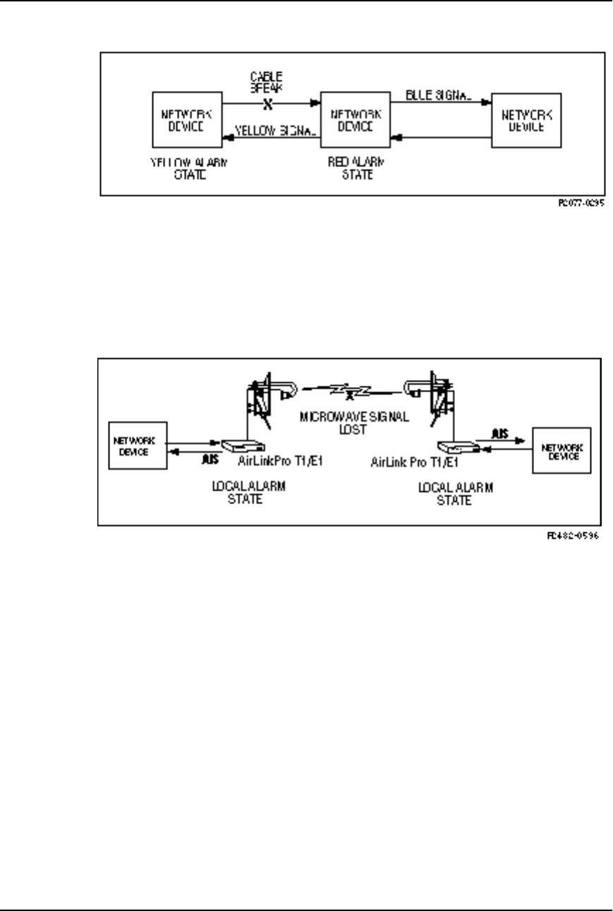
Airlink Pro T1/E1 Rack Mount Installer’s Guide
Operations and Maintenance
Rev. B - 1/97 4-7
Figure 4-1
Conventional Carrier Failure Response
If the microwave signal is lost between two AirLink Pro T1/E1 units
(Figure 4-2), both AirLink Pro T1/E1 units enter the local alarm state and send
an unframed, all-ones AIS (blue alarm) back toward its neighboring network
device. When the RF signal is regained, the AirLink Pro T1/E1 will come out of
the alarm state in about 10 ms.
Figure 4-2
AirLink Pro T1 Carrier Failure Response
If one of the three AirLink Pro T1/E1 Rack Mount loopback tests is active, AIS
is sent toward that portion of the link that has been excluded by the loop, so
the location and direction of the AIS depends upon which loopback test is
active. For more information about AIS and loopback tests, refer to “Loopback
Tests” in “Diagnostic Tools,” in this chapter.
Note that the other equipment in the network can take action upon receiving
alarm signals and might or might not restore service when the alarm clears.
Viewing the Event Queue
To view the event queue for the local unit, type the following command at the
AirLink Pro T1/E1 Rack Mount prompt:

AirLink Pro T1/E1 Rack MountInstaller’s Guide
Operations and Maintenance
Rev. B - 1/97
4-8
AIRLINK PRO T1/E1> query alarms
The system displays a list of alarm information similar to the following:
AIRLINK PRO T1/E1> query alarms
8: 8001: 20 SEP 1995 15:11:32 QRSS Test Started
7: C006: 20 SEP 1995 15:11:31 All Tests Cleared
6: 8007: 20 SEP 1995 15:09:50 FE Remote Loop Test Started
5: C006: 20 SEP 1995 15:09:50 All Tests Cleared
4: C006: 20 SEP 1995 15:07:51 All Tests Cleared
3: 8001: 20 SEP 1995 15:06:22 QRSS Test Started
2: C006: 20 SEP 1995 15:06:22 All Tests Cleared
1: C000: 20 SEP 1995 14:59:22 Event queue Cleared
NOTE Central office equipment, such as PBXs, and routers usually take some action when
receiving AIS, and might or might not automatically restore service after AIS is cleared.
When the signal is regained, it will halt AIS within 10 milliseconds.
When the event queue contains alarm messages, the most recent message with
the most recent time and date displays at the top of the list.
When there are more messages than will fit on one screen, you can page through
the messages by pressing <Return> to go forward one screen, or <B><Return> to
go back one screen. Press <Q> to exit (quit) the event queue display.
To view the event queue of the remote unit, use the command:
AIRLINK PRO T1/E1> remote query alarms
Resetting the Event Queue
To reset the event queue for the local unit, type the following command:
AIRLINK PRO T1/E1> reset alarms
The system prompts you to confirm the event queue reset request:
AIRLINK PRO T1/E1> reset alarms
Reset alarms: Are you sure? (Y/N)
When you enter y (yes) to confirm the request, the system clears the event
queue. If you enter n (no) or just press <Return>, the system ignores the event
queue reset request. If you query the event queue at this point, you should see
only one event, Alarm Queue Reset.
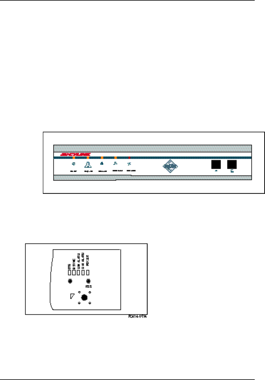
Airlink Pro T1/E1 Rack Mount Installer’s Guide
Operations and Maintenance
Rev. B - 1/97 4-9
The size of the Alarm Queue is 256 lines. No more alarms are logged when the
action is full.
AirLink Pro T1/E1 Rack Mount Indicators
The AirLink Pro T1/E1 Rack Mount has five front-panel indicators. These
indicators (LEDs) are duplicated on the rear panel. Refer to Figure 4-3 and 4-4.
Figure 4-3
Front Panel Indicators
Figure 4-4
Rear Panel Indicators

AirLink Pro T1/E1 Rack MountInstaller’s Guide
Operations and Maintenance
Rev. B - 1/97
4-10
Table 4-1
Visual Indicators
Name Color Function
Power Green Indicates that primary power is applied to the
equipment and the power supply is working.
Major Alarm Red When ON, indicates that one or more of the
following events has occurred.
-Transmit Power below threshold
-Synthesizer Loss of Lock (equipment failure)
-Transmitter Failure
- DTE Input Loss
- Radio Sync Loss
- Loss of primary burst sync (single sync bus)
- Loss of primary and backup burst sync (dual
sync bus)
Minor Alarm Yellow When ON, indicates that one or more of the
following events has occurred.
- RCV Input Level Below Threshold
- Unit has been placed in a test mode
- ES threshold exceeded
- UAS threshold exceeded
- Loss of primary or backup burst sync (dual
sync mode)
Sync Source Green When ON, indicates that this unit is a source of
burst sync for other AirLinks.
T1/E1 SIG Loss Red When ON, indicates the T1/E1 input signal from
the DTE has been lost or all zeros.
Acquiring Performance Information
Each AirLink Pro T1/E1 Rack Mount system maintains an internal database of
status and performance information that it uses, in part, to derive the events
that are stored in the event queue. The performance information categories
include:
❚Quasi-Random Signal Sequence Bit Error Rate (QRSS BER)
❚Errored Second (ES) counts (1-hour and 24-hour)
❚Unavailable Second (UAS) counts (1-hour and 24-hour)

Airlink Pro T1/E1 Rack Mount Installer’s Guide
Operations and Maintenance
Rev. B - 1/97 4-11
❚Receive Signal Quality (RSQ)
The AirLink Pro T1/E1 Rack Mount uses a Cyclic Redundancy Check (CRC)
error-checking system that constantly monitors the link error performance. The
CRC calculation is only performed on the T1/E1 payload. The CRC sequence is a
16-bit sequence that is appended to the end of the burst. The receiver on the
other end uses the same CRC-16 algorithm to perform the check on the received
burst and then compares the result. If the two checks do not match, the system
declares a CRC-16 error and increments the CRC-16 counter. Whether errored or
not, the CRC-16 sequence is removed and the payload is passed through to the
DSX-1 interface.
Viewing Performance Information
To view the performance information for the local unit, type the following
command at the AirLink Pro T1/E1 Rack Mount prompt:
AIRLINK PRO T1/E1> query performance
The system displays a list of performance information similar to the following:
AIRLINK PRO T1/E1> query performance
Site Name: Sunnyvale 2
QRSS BER: Unavailable
1 HR ES: 1
1 HR UAS: 0
24 HR ES: 1
24 HR UAS: 0
RSQ: 10
The following sections contain significance information about these categories.
QRSS BER
When the QRSS test is active, the Quasi-Random Signal Sequence Bit Error
Rate (QRSS BER) is the count of QRSS bit errors detected. The error counter
normally used to count CRC-16 errors is used instead to count QRSS bit errors.
When the QRSS test is active, the count of ES and UAS errors is suspended and
the existing values held, unaffected by the QRSS test. These counts are
reactivated when the QRSS test is terminated.
The results of the QRSS BER calculation are displayed in one of the following
forms:
unavailable When QRSS test is not selected, the word unavailable is
displayed.

AirLink Pro T1/E1 Rack MountInstaller’s Guide
Operations and Maintenance
Rev. B - 1/97
4-12
< 10E-xx When there are no errors, the result of the calculation is
displayed as < 10E-xx, where 10E-xx is the number of bits
transmitted, for example < 10E-08.
n.nE-xx When there are errors, the result of the calculation is
displayed as the bit error rate, for example 1.6E-07.
Errored Seconds
An errored second is any one-second interval during which there is a CRC-16
error. Errored seconds can be asynchronous, that is, they do not have to be
correlated with real time. An Errored Seconds (ES) total is maintained in a
database for the previous one hour and the previous 24 hours.
The one hour and 24 hour errored second databases are both updated each time
an errored second occurs. The one hour database is cleared to zero one hour after
the first errored second is logged. The 24 hour database is cleared to zero 24
hours after the first errored second is logged.
Unavailable Seconds
The link is declared unavailable during the time that Radio Sync Loss is
active.
RSQ
Receive Signal Quality (RSQ) is a figure of merit that is normalized on a scale
of 1 to 10, and is a function of the receive signal-to-noise ratio and signal-to-
interference ratio. A strong signal that is severely corrupted with interference
results in a normal receive signal indication and a low RSQ number.
Resetting Performance Counters
To reset the QRSS counter, type the following command at the AirLink Pro
T1/E1 Rack Mount prompt:
AIRLINK PRO T1/E1> reset qrss
The system prompts you to confirm the reset request:
AIRLINK PRO T1/E1> reset qrss
Reset QRSS: Are you sure? (Y/N)
When you enter y (yes) to confirm the request, the system clears the qrss counter.
If you enter n (no) or just press <Return>, the system ignores the reset request. If

Airlink Pro T1/E1 Rack Mount Installer’s Guide
Operations and Maintenance
Rev. B - 1/97 4-13
you query performance at this point, you should see that the counter has been
reset.
To reset the 1-hour and 24-hour ES and UAS counters, type the following
command at the AirLink Pro T1/E1 prompt:
AIRLINK PRO T1/E1> reset performance
The system prompts you to confirm the reset request:
AIRLINK PRO T1/E1> reset performance
Reset performance: Are you sure? (Y/N)
When you enter y (yes) to confirm the request, the system clears the ES and
UAS counters. If you enter n (no) or just press <Return>, the system ignores the
reset request. If you query performance at this point, you should see that the 1-
hour and 24-hour ES and UAS counters have been reset.
Diagnostic Tools
The AirLink Pro T1/E1 Rack Mount provides the following diagnostic tools:
❚A QRSS test
❚Two loop tests
The QRSS test and the loopback tests are initiated by commands entered
through the terminal user interface.
NOTE Only one test can be active at a time. If you attempt to start up a second test while a test
is running, the system terminates the first test and activates the second test.
Radio QRSS Testing
The QRSS signal is the Telco industry standard QRS test signal as defined in
ANSI Standard T1.403-1989. It is a 1,048,575-bit sequence generated by a 20-
stage shift register with feedback taps on stage 17 and 20. The sequence is
further altered to permit no more than 14 consecutive zeros. A QRSS test checks
the continuity and performance of a link (Figure 4-5). In QRSS testing, the
network traffic signal is interrupted and customer data on the radio signal is
replaced with a QRSS signal. When a QRSS test is initiated, QRSS
(unframed) is sent to the DTE. This causes a frame loss on any associated DTE
equipment that expects a framed DS1 signal thereby forcing an alarm condition.
This forces the equipment to go out of service.
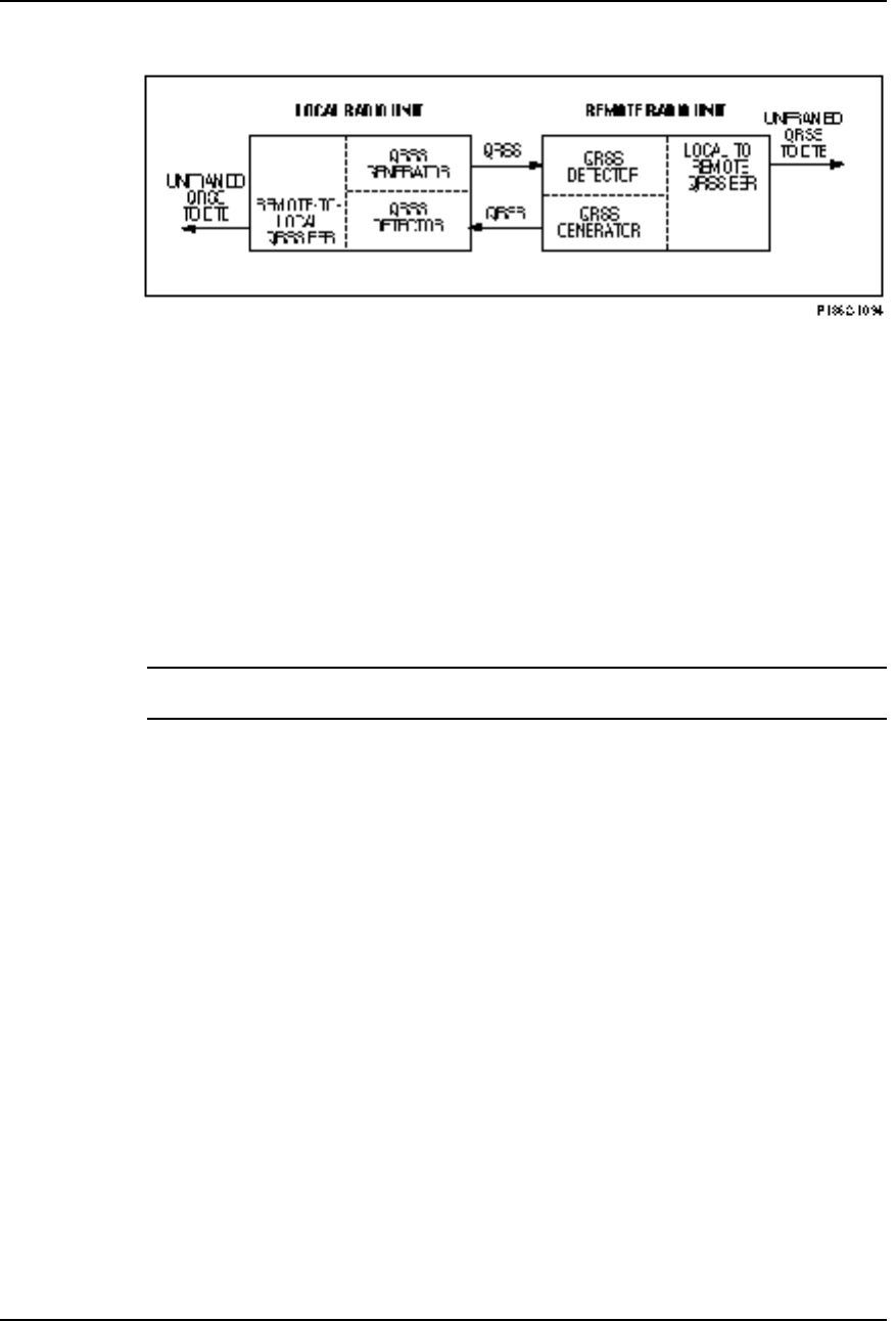
AirLink Pro T1/E1 Rack MountInstaller’s Guide
Operations and Maintenance
Rev. B - 1/97
4-14
Figure 4-5
AirLink Pro T1/E1 Rack Mount QRSS Test
Initiating the Test
The QRSS test is separate for each direction. This helps isolate unsymmetric
faults, such as RF interference versus antennae cable faults. The QRSS test can
be initiated by a command entered through the terminal user interface. You can
initiate a QRSS test from either end of the AirLink Pro T1/E1 Rack Mount link.
When the test is initiated, it is activated simultaneously from both ends of the
radio link. Each end of the link measures the received errors (independently)
and calculates the Bit Error Rate.
CAUTION This test interrupts the payload in the T1/E1 channel. Before initiating this test, you
should consider the impact of this test on the rest of the T1/E1 system.
To start a QRSS test on the local AirLink Pro T1/E1 Rack Mount, type the
following command at the AirLink Pro T1/E1 Rack Mount prompt:
AIRLINK PRO T1/E1> test qrss
The system prompts you to confirm the QRSS test:
AIRLINK PRO T1/E1> test qrss
WARNING: Start QRSS test? (Y/N)

Airlink Pro T1/E1 Rack Mount Installer’s Guide
Operations and Maintenance
Rev. B - 1/97 4-15
When you enter Y (yes) to confirm the request, the system starts the QRSS test.
AIRLINK PRO T1/E1> test qrss
WARNING: Start QRSS test? (Y/N) y
Site Name: Sunnyvale 2
OK
AIRLINK PRO T1/E1>
If you enter N (no) or just press <Return>, the system ignores the event queue
reset request. If you query the performance statistics at this point, you can check
the QRSS BER:
AIRLINK PRO T1/E1> query performance
Site Name: Sunnyvale 2
UWER BER: Unavailable
QRSS BER: 1.6E-07
1 HR ES: 1
1 HR UAS: 0
24 HR ES: 1
24 HR UAS: 0
RSQ: 10
The QRSS Bit Error Rate (BER) is measured from a starting point of 0.00E-99.
The QRSS BER is equal to:
Number of Errors
Test Duration (in seconds) x 1
1.544 x 10⁶
Terminating a QRSS Test
To terminate a QRSS test on the local AirLink Pro T1/E1 Rack Mount, type the
following command at the AirLink Pro T1/E1 Rack Mount prompt:
AIRLINK PRO T1/E1> reset test
The system prompts you to confirm the QRSS test termination request:
AIRLINK PRO T1/E1> reset test
Clear all tests? (Y/N)
When you enter Y (yes) to confirm the request, the system stops the QRSS test.
AIRLINK PRO T1/E1> reset test
Clear all tests? (Y/N) y
OK
AIRLINK PRO T1/E1>
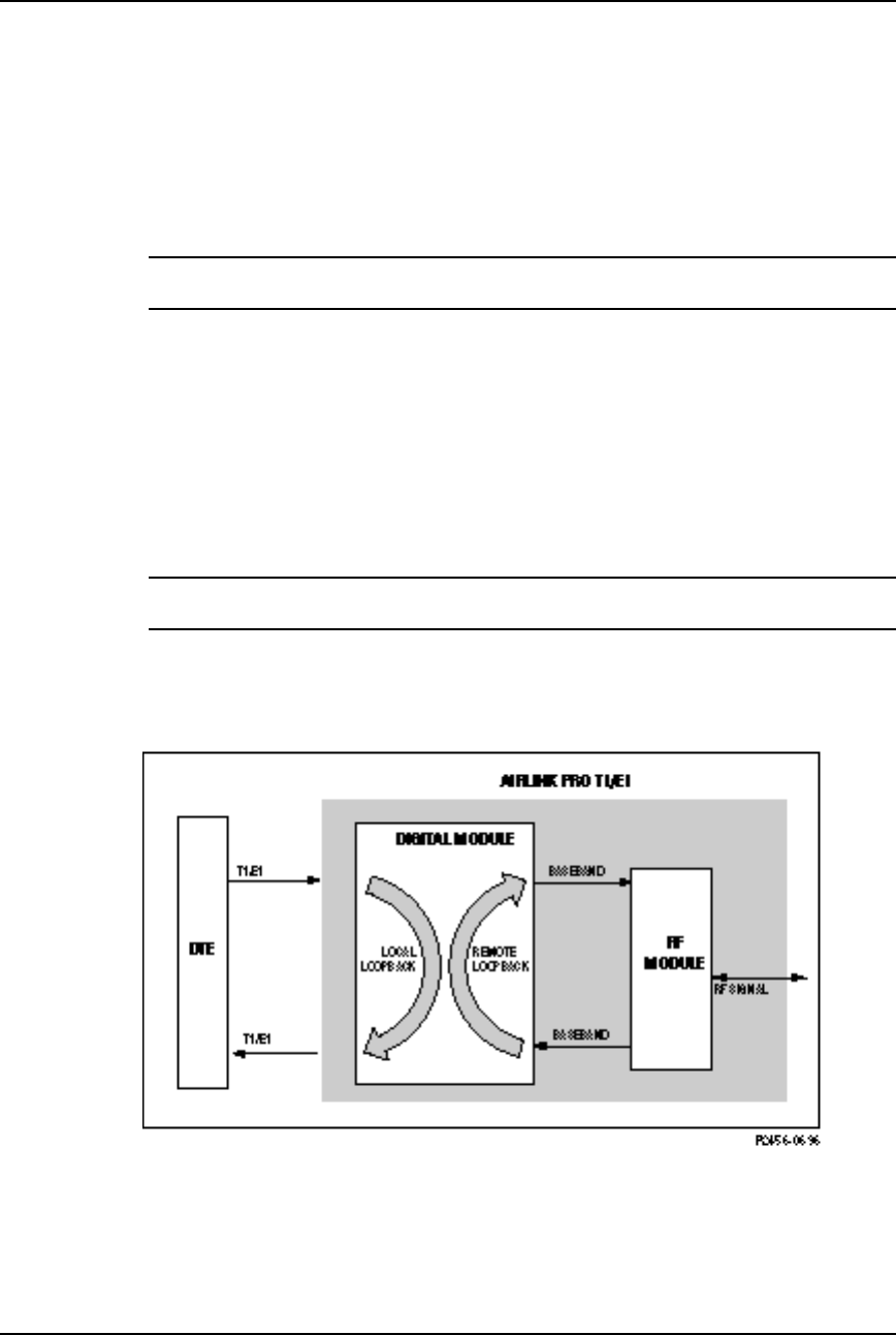
AirLink Pro T1/E1 Rack MountInstaller’s Guide
Operations and Maintenance
Rev. B - 1/97
4-16
Resetting The QRSS Error Register
To reset the QRSS error register and restart a test, type the following at the
command prompt:
AIRLINK PRO T1/E1> reset QRSS
NOTE The command RESET TEST does not reset the error count. The results of the last QRSS
test will remain on the QUERY PERFORMANCE screen until RESET QRSS is initiated.
Loopback Tests
The AirLink Pro T1/E1 Rack Mount provides the following loopback tests:
❚Local Loop test
❚Remote Loop test
NOTE You can initiate a loopback test for the local unit or the remote unit, but only one loopback
test can be active at a time.
Figure 4-6 shows a generalized view of the two loopback test types. Each of the
loopback tests and the conditions that apply during the test are described in
the following sections.
Figure 4-6
AirLink Pro T1/E1 Rack Mount Loopback Tests
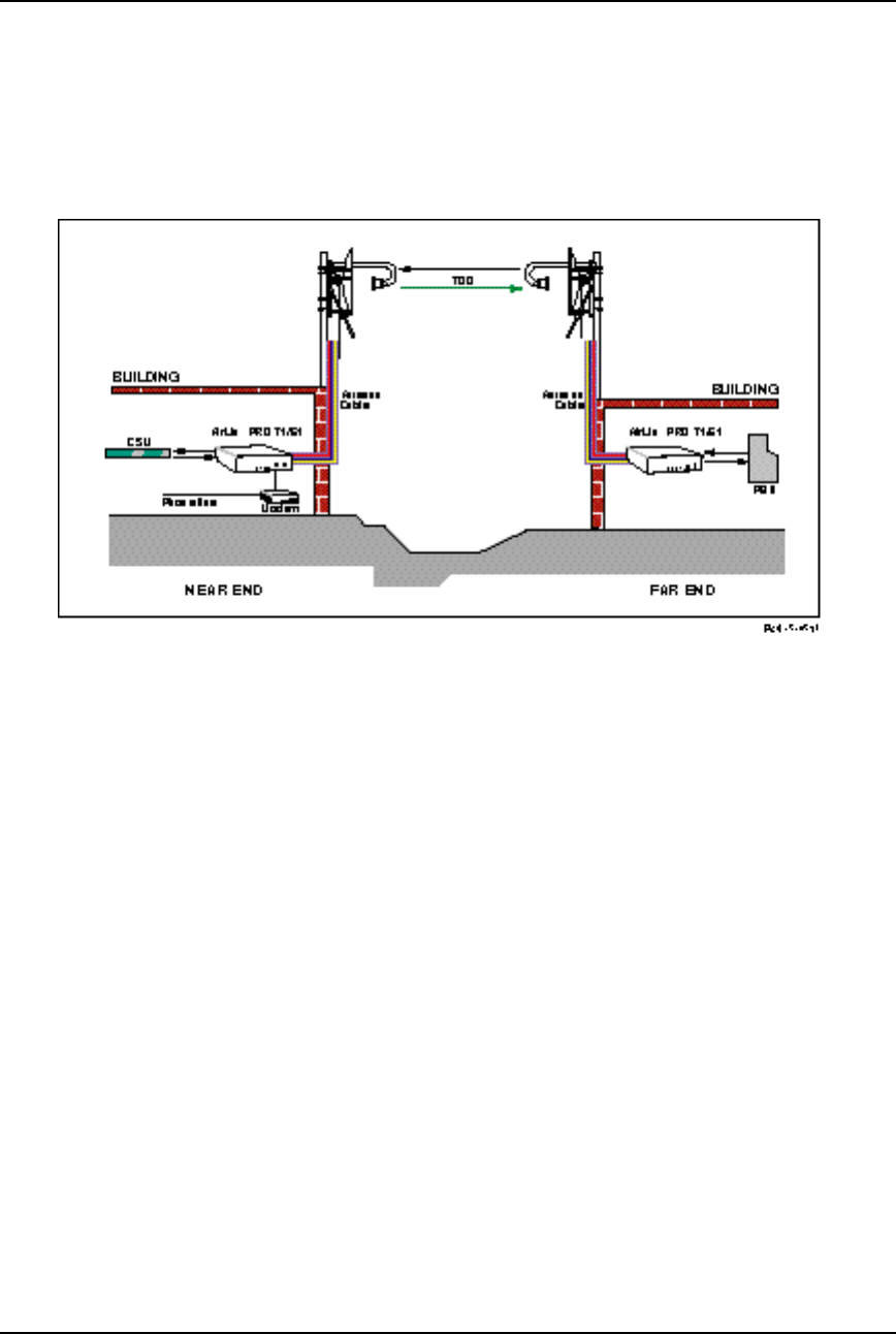
Airlink Pro T1/E1 Rack Mount Installer’s Guide
Operations and Maintenance
Rev. B - 1/97 4-17
Figure 4-7 shows end-to-end communication on a typical AirLink Pro T1/E1
Rack Mount link. Figures 4-8 and 4-9 show the two types of loopback tests in
operation.
Figure 4-7
AirLink Pro T1/E1 Rack Mount in Normal Operation
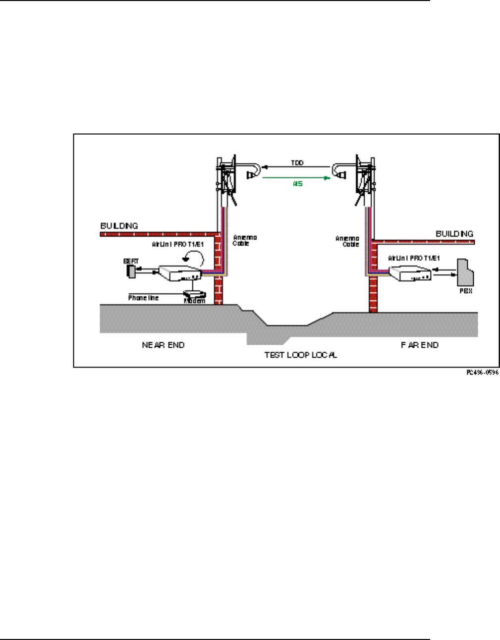
AirLink Pro T1/E1 Rack MountInstaller’s Guide
Operations and Maintenance
Rev. B - 1/97
4-18
Local Loop Test, Near End
The Local Loop test (Figure 4-8) sets a loopback at the T1/E1 interface of the
local (near end) radio unit and causes the T1/E1 signal to be returned to the
DTE. The AirLink Pro T1/E1 Rack Mount sends an unframed, all-ones Alarm
Indication Signal (AIS) toward the downstream (far end) AirLink Pro T1/E1
Rack Mount.
Figure 4-8
AirLink Pro T1/E1 Rack Mount in Local Loop Test, Near End
To start a local loopback, type the following command at the prompt:
AIRLINK PRO T1/E1> test loop local
The system prompts you to confirm the loop test:
AIRLINK PRO T1/E1> test loop local
WARNING: Start Local Loop test? (Y/N)
When you enter Y (yes) to confirm the request, the system starts the loop test.
OK
AIRLINK PRO T1/E1>
Site Name: Sunnyvale 2
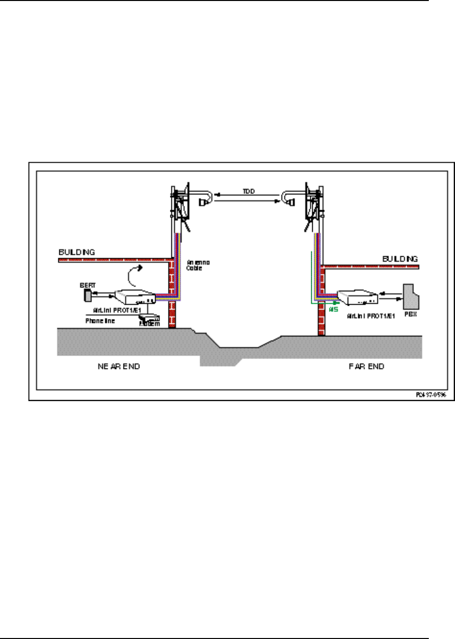
Airlink Pro T1/E1 Rack Mount Installer’s Guide
Operations and Maintenance
Rev. B - 1/97 4-19
Remote Loop Test, Near End
The Remote Loop test, Near End (Figure 4-9) causes the over-the-air received
T1/E1 signal to be looped back at the output of the receive T1/E1 signal
processing circuits. This loopback includes all of the radio circuits and
approximately 90% of the digital circuits. The affected AirLink Pro T1/E1
Rack Mount sends an unframed, all-ones Alarm Indication Signal (AIS) toward
the DTE.
Figure 4-9
AirLink Pro T1/E1 Rack Mount in Remote Loop Test, Near End
To start a remote loopback, type the following command at the AirLink Pro
T1/E1 Rack Mount prompt:
AIRLINK PRO T1/E1> test loop remote
The system prompts you to confirm the loop test:
AIRLINK PRO T1/E1> test loop remote
WARNING: Start Remote Loop test? (Y/N)
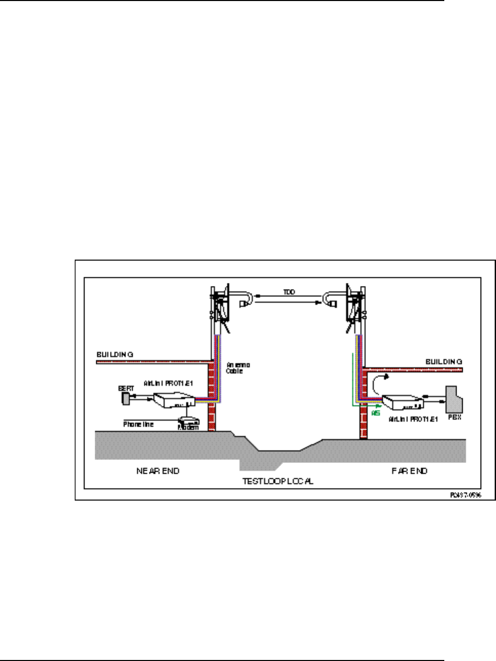
AirLink Pro T1/E1 Rack MountInstaller’s Guide
Operations and Maintenance
Rev. B - 1/97
4-20
When you enter Y (yes) to confirm the request, the system starts the
loop test.
OK
AIRLINK PRO T1/E1>
Site Name: Sunnyvale 2
Local Loop Test, Far End
The Local Loop test (Figure 4-10) sets a loopback at the T1/E1 interface of the
remote (far end) radio unit and causes the T1/E1 signal to be returned to the
DTE. The AirLink Pro T1/E1 Rack Mount sends an unframed, all-ones Alarm
Indication Signal (AIS) toward the downstream (near end) AirLink Pro T1/E1
Rack Mount.
Figure 4-10
AirLink Pro T1/E1 Rack Mount in Local Loop Test, Far End
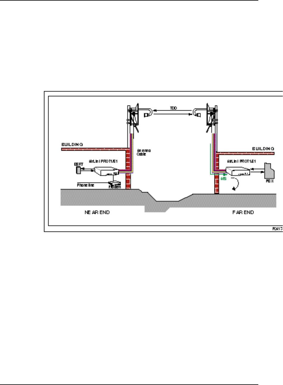
Airlink Pro T1/E1 Rack Mount Installer’s Guide
Operations and Maintenance
Rev. B - 1/97 4-21
Remote Loop Test, Far End
The Remote Loop test, Far End (Figure 4-11) causes the over-the-air received
T1/E1 signal to be looped back at the output of the receive T1/E1 signal
processing circuits. This loopback includes all of the radio circuits and
approximately 90% of the digital circuits. The affected AirLink Pro T1/E1
Rack Mount sends an unframed, all-ones Alarm Indication Signal (AIS) toward
the DTE.
Figure 4-11
AirLink Pro T1/E1 Rack Mount in Remote Loop Test, Far End
To start a remote loopback, type the following command at the AirLink Pro
T1/E1 Rack Mount prompt:
AIRLINK PRO T1/E1> remote test loop remote
The system prompts you to confirm the loop test:
AIRLINK PRO T1/E1> Sending command downline. Please Wait.
WARNING: Start Remote Loop test? (Y/N)
When you enter Y (yes) to confirm the request, the system starts the
loop test.

AirLink Pro T1/E1 Rack MountInstaller’s Guide
Operations and Maintenance
Rev. B - 1/97
4-22
OK
AIRLINK PRO T1/E1>
Site Name: Sunnyvale 1
If you query the status information while the test is running, you can verify
that the test is running:
AIRLINK PRO T1/E1> query status
Site Name: Sunnyvale 2
DTE Loss: NO
Radio Sync Loss: NO
Burst Sync Loss: N/A
Test in Progress: Remote Loop
DTE AIS: OFF
RF AIS: OFF
Tx Fail: NO
Rx Power: -60.5 dBm
Tx Power: 12.0 dBm
Temperature: 5 C
Rack Mount Unit Working with Pro T1 Ruggedized Unit
The following describes the differences between an AirLink Pro T1 Rack Mount
Unit and the AirLink Pro T1 Ruggedized Unit.
• A Ruggedized unit has an option to use an Access Unit, and if the Access
Unit is installed, there is an additional remote loopback command called
"Access Unit Remote Loop."
• A Rack-Mount unit has software set-ability of the E1 Interface (balanced or
unbalanced). A Ruggedized unit does not have this option. This option
appears in the Rack-Mount unit list of "SET" commands.
• A Rack-Mount unit has a two-wire or four-wire Order wire option. The
Ruggedized unit has only two-wire. This option appears in the list of "SET"
commands.
NOTE When an AirLink Pro T1/E1 Rack Mount is operating end-to-end with and AirLink Pro T1/E1
Ruggedized unit, the Order wire option in the Airlink Pro Rack Mount unit MUST be set to
two-wire.

Airlink Pro T1/E1 Rack Mount Installer’s Guide
Operations and Maintenance
Rev. B - 1/97 4-23
Features of Various Units
The following table shows the features the AirLink Pro T1/E1 Rack Mount as
compared to the AirLink Pro T1/E1 Ruggedized Unit.
Ruggedized with
Access Unit Ruggedized without
Access Unit Rack Mount
Unit
Access Unit Loop Yes No No
Order Wire 2 wire 2 wire 2 wire or 4 wire
E1 Interface Select Hardware Jumpers Hardware Jumpers Software
Selected

Rev. B - 1/97 A-1
A
APPENDIX
PPENDIX A
A
Messages
Messages
This chapter describes AirLink Pro T1/E1 Rack Mount Messages.
Inside this chapter:
General Information ............................................................ A-2
Fault Messages .................................................................... A-3
Alarm Messages .................................................................. A-3
Advisory Messages ............................................................. A-4
Status Messages ................................................................ A-5

AirLink Pro T1/E1 Rack Mount Installer’s Guide
Messages
Rev. B - 1/97
A-2
General Information
AirLink Pro T1/E1 Rack Mount messages are only accessible through a terminal
device connected to a Terminal port on the AirLink Pro T1/E1 Rack Mount. All
messages are coded with a four-digit alphanumeric code so that higher-level
network management software can detect the message. These messages are
grouped into the following categories:
❚Fault messages (0xxx)
❚Alarm messages (4xxx)
❚Advisory messages (8xxx)
❚Status messages (Cxxx)
When you enter a query alarms command, the system displays a list of alarm
and event information similar to the following:
AIRLINK T1> query alarms
8: 8001: 20 SEP 1994 15:11:32 QRSS Test Started
7: C006: 20 SEP 1994 15:11:31 All Tests Cleared
6: 8007: 20 SEP 1994 15:09:50 FE Remote Loop Test Started
5: C006: 20 SEP 1994 15:09:50 All Tests Cleared
4: C006: 20 SEP 1994 15:07:51 All Tests Cleared
3: 8001: 20 SEP 1994 15:06:22 QRSS Test Started
2: C006: 20 SEP 1994 15:06:22 All Tests Cleared
1: C000: 20 SEP 1994 14:59:22 Event queue Cleared
When the event queue contains alarm messages, the most recent message is
displayed at the top of the list, with the most recent time and date.
When there are more messages than will fit on one screen, you can page through
the messages by pressing <Return> to go forward one screen, or <B><Return> to
go back one screen. Press <Q> to exit (quit) the event queue display.

AirLink Pro T1/E1 Rack Mount Installer’s Guide
Messages
Rev. B - 1/97 A-3
Fault Messages
Fault messages (see Table A-1) indicate service-affecting failures; contact
Cylink Customer Support for help.
Table A-1
Fault Messages
Code Message
0000 Transmit Power Below Threshold
0001 Synthesizer Loss of Lock
0002 Transmitter Failure
Alarm Messages
Alarm messages (see Table A-2) indicate conditions or events that insert an
entry into the Event queue and may cause an alarm state. These are generally
conditions that can be resolved by an operator in the field.
Table A-2
Alarm Messages
Code Message
4004 Receive Power Below Threshold
4005 DTE Input Loss
4006 Radio Sync Loss
4008 Powered Up
4011 Primary Burst Sync Source Loss
4012 Backup Burst Sync Source Loss
4013 No Burst Sync Source

AirLink Pro T1/E1 Rack Mount Installer’s Guide
Messages
Rev. B - 1/97
A-4
Advisory Messages
Advisory messages (see Table A-3) indicate conditions or events that insert an
entry into the Event queue, but do not cause an alarm state. Except for “Event
Queue Full,” which does not indicate a service-affecting condition, these
messages generally indicate that the system is working, but that something the
operator has done—such as starting a test—is preventing data from passing
from one end of the link to the other.
Table A-3
Advisory Messages
Code Message
8000 Event Queue Full
8001 QRSS Test Started
8002 Local Loop Test Started
8003 Remote Loop Test Started
8005 FE QRSS Test Started
8006 FE Local Loop Test Started
8007 FE Remote Loop Test Started
8009 1 HR ES Threshold
800A 1 HR UAS Threshold
800B 24 HR ES Threshold
800C 24 HR UAS Threshold
800D Modem Busy
800E No Answer
800F No Modem
8010 No Dialtone

AirLink Pro T1/E1 Rack Mount Installer’s Guide
Messages
Rev. B - 1/97 A-5
Status Messages
Status messages (see Table A-4) indicate the negation of another alarm or
advisory condition or event.
Table A-4
Status Messages
Code Message
C000 Event Queue Reset
C001 Receive Power Above Threshold
C002 Transmit Power Above Threshold
C003 DTE Input Loss Ends
C004 Synthesizer Loss of Lock Ends
C005 Radio Sync Loss Ends
C006 All Tests Cleared
C008 Transmitter Failure Ends
C011 Primary Burst Sync Source Recovered
C012 Backup Burst Sync Source Recovered
C013 Burst Sync Recovered

Rev. B - 1/97 B-1
A
APPENDIX
PPENDIX B
B
Specifications
Specifications
This appendix is the reference for the specifications of the AirLink Pro
T1/E1 Rack Mount system.
Inside this chapter:
General Specifications........................................................B-2
Interface Specifications.....................................................B-4
Signal-to-Pin Assignments...............................................B-11
Terminal and Modem
Adaptor Cables...........................................................B-16
Configuration Defaults.....................................................B-19

AirLink Pro T1/E1 Rack Mount Installer’s Guide
Specifications
Rev. B - 1/97
B-2
AirLink Pro T1/E1 Rack Mount Specifications
Typical of the design quality and extensive testing, the AirLink Pro family is
designed to meet the following specifications:
Environmental Requirements
Temperature
Operating: -40C to +60C (-40 to +140 Fahrenheit)
Storage: -40C to +60C
Humidity
Operating: 10% to 95% non-condensing
Storage: 10% to 95% non-condensing
Altitude
200 feet below sea level to 13,000 feet above sea level
Electromagnetic Interference (EMI)
FCC Part 15 Class B
EN 55022 Class B
Safety
The AirLink Pro T1/E1 Rack Mount units are low-voltage devices and are
excluded from Underwriters Laboratories (UL) coverage. The optional AC/DC
power supply is UL listed.
Fire Resistance
All plastic parts and printed circuit boards are made from materials that
comply with UL flame retardant requirements for central office quality.

AirLink Pro T1/E1 Rack Mount Installer’s Guide
Specifications
Rev. B - 1/97 B-3
Shock
Transportation/Handling Shock
Drop Test NSTA Project 2A for packaged devices
Operation Shock
Bellcore TR-TSY-000487, Section 5.1.4.9 (Vibration Test-Low Level)
Vibration
Operational Vibration
Bellcore TR-TSY-000487, Section 5.1.4.11 (Vibration Test-Low Level)
Transportation Vibration
ASTM D 4728 Random Vibration Testing
Truck/Air Spectrum (IG, 5-200HZ-according to the general requirements of
ASTM D 4728)
Quality
The Cylink manufacturing organization has been certified by the British
Approvals Board for Telecommunications (BABT) with Production Quality
Assurance Approval (PQAA) since November 19, 1992. PQAA is similar to ISO
9002, and emphasizes safety and compliance affecting processes, as well as
quality methods. BABT conducts annual audits to verify continued compliance.
Operational Reliability
During the product design process, mean time between (MTBF) is calculated
using the process defined in Bellcore technical reference TR-NWT-000332. For
the AirLink T1 unit, the MTBF hours are 77,503.

AirLink Pro T1/E1 Rack Mount Installer’s Guide
Specifications
Rev. B - 1/97
B-4
Table B-1
Power
Input Voltage 21 to 56 VDC
Input Power 25 Watts (Maximum)
Input Current 1.0 Amps @ 24 Volts
500 Ma @ 48 Volts
Input Polarity Input is floating. Either input may be
grounded.
Input Protection Nominal fuse = 2.0 A Slow Blow
Input Reverse
Voltage Protection Provided. Series diode. No current will flow if
the input voltage is reversed.
NOTE No internal fusing is provided, because to do so would violate the specifications of
UL1459 section 70. (No fusing is allowed in the grounded side of a DC input circuit unless
the hot side is also fused.) When the fuse in the hot side blows, the fuse in the grounded
input must
also
blow. Since this equipment accepts either polarity, external circuit
protection
must be
provided in the hot side of the feeder circuit.
Interface Specifications
This section contains specifications for the two major interfaces of the AirLink
Pro T1/E1 Rack Mount:
❚T1/E1 DTE interface
❚Radio interface

AirLink Pro T1/E1 Rack Mount Installer’s Guide
Specifications
Rev. B - 1/97 B-5
T1 DSX-1 Interface
The DS1 interface in the AirLink Pro T1 performs according to the
specifications of DSX-1 cross connects as specified in ANSI T1.102-1987 and
Bellcore # TR-NWT-000 499.
Table B-3
T1 DSX-1 Interface
Transmission Line Rate 1.544 Mbps ± 150 bps
Line Coding Bipolar 8-Zero Substitution (B8ZS) or
Alternate Mark Inversion (AMI)
Impedance 100 Ω ±5%
Pulse Shape An isolated pulse shall fit the template shown in T1.102,
Figure 1. The pulse amplitude shall be between 2.4 and
3.6 volts, measured at the center of the pulse.
Cable Length The pulse shape must meet the mask when the
equipment is connected to a DSX-1 cross connect
located at any distance from 0 to 655 feet (200 meters)
with #22 AWG ABAM cable (or equivalent).
Loss of Signal Threshold Loss of signal is reported upon detection of 175 ± 75
consecutive zeros.
Power Level For an all-ones transmitted pattern, the power in a band
no wider than 3 kHz centered at 772 kHz shall be
between 12.6 and 17.9 dBm. The power in a band no
wider than 3 kHz centered at 1.544 MHz shall be at
least 29 dB below that at 772 kHz.
Jitter The jitter performance of the AirLink Pro T1 meets or
exceeds all input tolerance, output generation, and
transfer function specifications of AT&T Publication
62411. 1983 Edition and Belicore TR-TSY-000499
DSX Line Equalization User-selectable pre-distortion to offset cable lengths
of:
0 - 133 feet 0 - 40 meters
133 - 266 feet 40 - 81 meters
266 - 399 feet 81 - 122 meters
399 - 533 feet 122 - 162 meters
533 - 655 feet 162 - 200 meters

AirLink Pro T1/E1 Rack Mount Installer’s Guide
Specifications
Rev. B - 1/97
B-6
Airlink Pro E1 Interface General Specifications
The E1 interface in the AirLink E1 performs according to the specifications in
the ITU-T Fascicle III.4 Recommendation G.703, Section 6.
Transmission Line Rate 2.048 Mbps ± 200 bps
Line Coding High Density Bipolar 3 (HDB3) or
Alternate Mark Inversion (AMI)
Impedance 120 Ω ±5% (balanced)
75 Ω ±5% (unbalanced)
E1 Interface Output Specifications
Pulse Amplitude 3.0 volts ±10% (balanced)
2.3 volts ±10% (unbalanced)
Pulse Width 244 nanoseconds
Pulse Shape An isolated pulse shall fit the template shown in
Recommendation G.703, Figure 15.
Pulse Imbalance The ratio of the amplitude and pulse width of the positive
and negative pulse shall not exceed ±5%.
Output Jitter Generation Refer to Recommendation G.823, Figure 1 and Table 1.
The maximum output jitter shall not exceed the following
limits:
1.5 U.I. in a bandwidth from 20 Hz to 100 kHz.
0.2 U.I. in a bandwidth from 18 kHz to 100 kHz.

AirLink Pro T1/E1 Rack Mount Installer’s Guide
Specifications
Rev. B - 1/97 B-7
E1 Interface Input Specifications
Signal Level No more than 6 dB loss, referenced to the pulse mask.
The transmission medium is assumed to have an F1/2
characteristic and the loss is measured at 1024 kHz.
Return Loss Frequency Range (kHz) Return Loss (dB)
51 to 102 12
102 to 2048 18
2048 to 3072 14
Loss of Signal Threshold Loss of signal is reported upon detection of 175 ± 75
consecutive zeros.
Input Jitter Tolerance The jitter performance of the AirLink E1 meets or
exceeds all input tolerance, output generation, and
transfer function specifications of Fascicle III.4,
Recommendation G.703.
Radio Interface
Table B-4 (for both T1 and E1)
General
Frequency Band 5.725 to 5.850 GHz
Carrier Frequency 5.7875 GHz
Allocated Bandwidth 125 MHz
Occupied Bandwidth T1=95 MHz
E1=120 MHz
Number of Channels 1
Modulation Type GFSK
Spreading Method Direct Sequence
Spreading Code Eight sets of 32-bit PN sequences
Processing Gain >10 dB
Operating Protocol Time Division Duplex
Frequency Stability 10 ppm
System Gain T1=100 dB
E1=98 dB
End-to-End Delay
End-to-End Delay T1=3 ms
E1=2.2 ms

AirLink Pro T1/E1 Rack Mount Installer’s Guide
Specifications
Rev. B - 1/97
B-8
Table B-5
Transmitter
Power Output 100 mW (20 dBm) maximum
Load Impedance: 50 Ω nominal
Tx Output Detector Accuracy ± 2 dB
Output Level Control Digitally controlled attenuator,
Dynamic Range: -4 to +20 dBm
Resolution: can be set in 1 dB steps
Accuracy: ± 2 dB @ 25° C; ± 3 dB over operating
temperature range
Output Level Detector Generates an alarm when the output falls below the user
defined threshold
RF Port Protection Open or Short circuit protected

AirLink Pro T1/E1 Rack Mount Installer’s Guide
Specifications
Rev. B - 1/97 B-9
Table B-6
Receiver
Input Impedance 50 Ω nominal. VSWR < 2:1 over the frequency and
temperature range
RF Input Protection +10 dBm continuous without damage
Maximum RF Input Power
Without Causing Dribbling Errors -25 dBm
Receiver Dynamic Range > 40 dB
Receive Signal Strength ± 2 dB
Receive Level Detector Dynamic range: 40 dB
Accuracy: ± 3 dB
Frequency Band 5.725 to 5.850 GHz
Noise Figure 5.5 dB maximum, measured from the antenna port
RSQ Detector Dynamic Range: 0 - 10
Operating Range: 9 - 10
Receiver Sensitivity (dBm) T1 E1
10-6 Guaranteed -80 -78
10-6 Typical -82 -80
10-9 Guaranteed -77 -75
10-9 Typical -79 -77

AirLink Pro T1/E1 Rack Mount Installer’s Guide
Specifications
Rev. B - 1/97
B-10
Table B-7
2-wire Order Wire
Terminating Impedance 600 Ω ± 5%
Coding Method 64 kbps PCM
Open Circuit Battery Feed Voltage 24 VDC
Battery Feed Current 100 mA maximum
Maximum Input Signal Meets V.21 and V.32 modem specifications; no
ringing required
End-end loss 0 dBm
Table B-8
4-wire Order Wire
Terminating Impedance 400 Ω ± 5%
Coding Method 64 kbps PCM
Nominal input 0 dBm
Nominal output 0 dBm
End-end loss 0 dBm

AirLink Pro T1/E1 Rack Mount Installer’s Guide
Specifications
Rev. B - 1/97 B-11
Signal-to-Pin Assignments
This section presents the pin assignments and functions for connector and
captive-wire terminal blocks on the AirLink Pro T1/E1 Rack Mount:
❏Network Management
❏AirLink Control
❏AirLink Pro T1/E1 Rack Mount
❏CSU/DSU
❏T1/E1 DTE
❏CSU SEL
❏Power & Alarm
❏Order Wire
NOTE Occasionally, industry names and terms change. For example, the EIA RS-xxx standards
are now referred to as the EIA/TIA-xxx standards, a change that reflects their acceptance
as standards by the Electronic Industries Association (EIA) and Telecommunications
Industry Association (TIA).
Similarly, the former Consultative Committee for International Telegraph and Telephone
(CCITT) is now referred to as the International Telecommunication Union
Telecommunication Standardization Sector (ITU-T).
Terminal
Connector Location: Two Connectors. AirLink Pro T1/E1 Rack Mount Front and Rear
Panels
Connector Type: RJ-11 Modular Jack
Table B-9
Interface signals are per EIA/TIA-232.
Pin Signal/Function Direction
1No Connection -----
2 Received Data To AirLink Pro T1/E1 Rack Mount
3Circuit Ground Not Applicable
4 Circuit Ground Not Applicable
5 Transmitted Data From AirLink Pro T1/E1 Rack
Mount
6 No Connection -----

AirLink Pro T1/E1 Rack Mount Installer’s Guide
Specifications
Rev. B - 1/97
B-12
2-wire Order Wire
Connector Location: AirLink Pro T1/E1 Rack Mount Front Panel
Connector Type: RJ-11 Modular Jack
Table B-10
2-wire Order Wire
Pin Signal/Function Direction
1No Connection -----
2 No Connection -----
3Order Wire Tip Not Applicable
4Order Wire Ring Not Applicable
5 No Connection -----
6 No Connection -----
4-wire Order Wire
Connector Location: AirLink Pro T1/E1 Rack Mount Rear Panel
Connector Type: 4-Pin Captive Wire Terminal Block
Table B-11
4-wire Order Wire
Pin Signal/Function Direction
1OUT-T Orderwire Output
2OUT-R Orderwire Output
3 IN-T1 Orderwire Input
4 IN-R1 Orderwire Input
Network Management
Connector Location: AirLink Pro T1/E1 Rack Mount Rear panel
Connector Type: 9-Pin Male Subminiature “D”
This connector is configured per EIA/TIA-574. Interface signals levels are for EIA/TIA-232.

AirLink Pro T1/E1 Rack Mount Installer’s Guide
Specifications
Rev. B - 1/97 B-13
Table B-12
Network Management
Pin EIA/TIA
Circuit ITU-T
Circuit Description Direction
1CF 109 Received Line Signal
Detector To AirLink Pro T1/E1 Rack Mount
2BB 104 Received Data To AirLink Pro T1/E Rack Mount
3BA 103 Transmitted Data From AirLink Pro T1/E1 Rack
Mount
4 CD 108.2 DTE Ready From AirLink Pro T1/E1 Rack
Mount
5 AB 102 Signal Common -----
6 CC 107 DCE Ready To AirLink Pro T1/E1 Rack Mount
7CA 105/133 Request to Send/Ready
for Sending From AirLink Pro T1/E1 Rack
Mount
8 CB 106 Clear to Send To AirLink Pro T1/E1 Rack Mount
9CE 125 Ring Indicator To AirLink Pro T1/E1 Rack Mount
Table B-13
DC Power
Connector Location: AirLink Pro T1 Rear panel
Connector Type: Four-Pin Captive Wire term Block
Pin Signal/Function Explanation
1V- DC Input Negative
2 V- DC Input Negative
3 GND Ground
4 GND Ground
5 V+ DC Input Positive
6 V+ DC Input Positive

AirLink Pro T1/E1 Rack Mount Installer’s Guide
Specifications
Rev. B - 1/97
B-14
Table B-14
Major Alarm
Connector Location: AirLink Pro T1 Rear Panel
Connector Type: Four-Pin Captive Wire term Block
Pin Signal/Function Explanation
1COM Alarm Relay Common
Contact
2 NO Alarm Relay Normally Open
Contact
3 NC Alarm Relay Normally Closed
Contact
4 GND Ground
5CSU-SEL Strap from Pin 5 to Pin 6
6CSU-SEL Activates the CSU SEL relay
Table B-15
Minor Alarm
Pin Signal/Function Explanation
1COM Alarm Relay Common
Contact
2 NO Alarm Relay Normally Open
Contact
3 NC Alarm Relay Normally Closed
Contact
4 GND Ground

AirLink Pro T1/E1 Rack Mount Installer’s Guide
Specifications
Rev. B - 1/97 B-15
CSU
Connector Location: Rear Panel
Connector Type: Six-Pin Captive Wire Terminal Block
Table B-16
CSU
Pin Signal Description Direction
1IN Input Data (Tip) To AirLink Pro T1
2IN Input Data (Ring) To AirLink Pro T1
3GND Cable Shield Ground
4OUT Output Data (Tip) From AirLink Pro T1
5OUT Output Data (Ring) From AirLink Pro T1
6GND Cable Shield Ground
DTE
Connector Location: Rear Panel
Connector Type: Six-Pin Captive Wire from Block
Table B-17
DTE
Pin Signal Description Direction
1IN Input Data (Tip) To AirLink Pro T1
2IN Input Data (Ring) To AirLink Pro T1
3GND Cable Shield Ground
4OUT Output Data (Tip) From AirLink Pro T1
5OUT Output Data (Ring) From AirLink Pro T1
6GND Cable Shield Ground
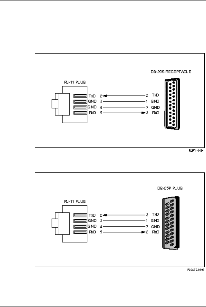
AirLink Pro T1/E1 Rack Mount Installer’s Guide
Specifications
Rev. B - 1/97
B-16
Terminal and Modem Adapter Cables
Use the following figures to fabricate cables to connect terminals and modems to
the AirLink Pro T1.
Figure B-1
Terminal Cable: AirLink Pro T1 Terminal Port to a DB-25 Terminal Port
Figure B-2
Modem Cable: AirLink Pro T1 Terminal Port to a DB-25 Modem Port
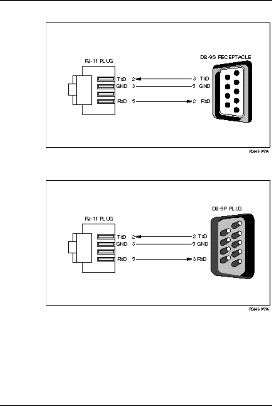
AirLink Pro T1/E1 Rack Mount Installer’s Guide
Specifications
Rev. B - 1/97 B-17
Figure B-3
Terminal Cable: AirLink Pro T1 Terminal Port to a DB-9 Terminal Port
Figure B-4
Modem Cable: AirLink Pro T1 Terminal Port to a DB-9 Modem Port

AirLink Pro T1/E1 Rack Mount Installer’s Guide
Specifications
Rev. B - 1/97
B-18
Terminal Configuration
Before connecting the ASCII terminal to the unit, configure the terminal with
the following parameters:
Terminal Mode = VT100
Column = 80
Autowrap = ON
Monitor Mode = OFF
Cursor Keys = Normal
Newline Mode = ON
Character Set = DEC Supplemental
Key Code = ASCII
Break key = ON
Minimum Break Length = 2 character times (17 msec.)
Data/Parity = 8/No Parity
Stop Bits = 1
Transmit Rate = 19200, 9600, 4800, 2400, or 1200 bps
Auto Answerback = OFF
Comm = FDX (No Echo)
RS232 Data Leads Only (RxD and TxD)
Local Echo = OFF
A Break code is recognized by many systems as an attention signal, and most
systems vary as to the length of time Break must be generated before it is
recognized. Most terminals and terminal emulation software allow you to set
the length of the Break signal.
The minimum Break length for the AirLink Pro T1/E1 Rack Mount is two
character times or approximately 17 milliseconds. A longer Break length
(limited by the range available from the setup program of the terminal or
terminal emulation software) has no effect on the AirLink Pro T1/E1 Rack
Mount.
For more information about terminal configuration, see the AirLink Site
Planning Guide.

AirLink Pro T1/E1 Rack Mount Installer’s Guide
Specifications
Rev. B - 1/97 B-19
Configuration Defaults
The following table lists default configuration/operational values.
Table B-18
Configuration Defaults
Parameter Value Notes
Application 4. Master Unit in a Point-to-
Point Link
Site Name (Blank)
Burst Mode Normal
Coding B8ZS
Equalization 0 (0 - 133 feet)
PN Code 1
RF Power 0 (dBm)
Alarm Reporting Immediate
Alarm level Status
Date 01/01/91
Time 00:00:00 (midnight)
Password <Return>
1 HR ES Threshold 1
1 HR UAS Threshold 1
24 HR ES Threshold 1
24 HR UAS Threshold 1
Rx Power Threshold -75 (dBm)
Tx Power Threshold -6 (dBm)
The prompt is reprinted when the <ENTER> key is pressed and the command
line is empty. All command responses end with a new prompt. When printing
formatted text, tabs are not used; all alignment is performed with spaces to
remove any problems associated with the interpretation of tab stops on
customer equipment. If an incomplete command line is issued, the text to finish
the command line is returned.

AirLink Pro T1/E1 Rack Mount Installer’s Guide
Specifications
Rev. B - 1/97
B-20
Dialout Parameter Defaults
Table B-19
AirLink Pro T1/E1 Rack Mount Dialout Parameters
Parameter Default
ALARM HOLDOFF 10 seconds
ANSWER TIMEOUT 30 seconds
CONNECTION TIMEOUT 3600 seconds (1 hour)
DIAL FORMAT TONE
DIAL HOLDOFF 10 minutes
DIAL LEVEL ALARM
MODEM MODE DISABLED
MODEM RATE 9600
MODEM RTS CONTINUOUS
MODEM CTS IGNORE
MODEM DTR CONTINUOUS
MODEM VOLUME LOW
MODEM XOFF IGNORE
PHONE 1 (blank)
PHONE 2 (blank)
REPEAT COUNT 10 events
RINGCOUNT 1

Rev B - 1/97 C-1
A
APPENDIX
PPENDIX C
C
Commands
Commands
This command-list associated with the AirLink Pro T1/E1 Rack Mount
covers the keywords to logging in and out, testing, local and remote
access, and how to use help.

Airlink Pro T1/E1 Rack Mount Installer’s Guide
Commands
Rev. B - 1/97
C-2
Command Keyword List
This section lists the available command keywords and operands used to set,
view, or change configuration parameter values. The command line syntax uses
a set of keywords to get or set parameters, to query status, and to reset counter
and queues. Only the first four letters of each keyword are necessary. Add
space between keywords.
Setup Commands
HELP
LOCAL (Local is implied and doesn’t need to be typed in)
REMOTE
SET
APPLICATION 1........8
1. Primary Master in a Hub
2. Secondary Master in a Hub
3. Master Unit at a Repeater
4. Master Unit in a Point to Point
5. Slave Unit at a Repeater Site
6. Slave Unit in a Point-to-Point Link
7. Secondary Master in a protected Link
8. Backup Master in a Hub
SITE NAME: { Up to 60 Characters}
BURST MODE: {Normal | Test}
CODING: {HDB3 | B8ZS | AMI}
EQUALIZATION: { 0 | 133 | 266 | 399 | 533}
HUBSYNC: {Single | Dual}
INTERFACE: {Balanced | Unbalanced}
ORDERWIRE: {2W | 4W}
PN CODE: {1...8}
RF POWER: {-3...20}

AirLink Pro T1/E1 Rack Mount Installer’s Guide
Commands
Rev. B - 1/97 C-3
ALARM REPORTING: {Request | immediate}
ALARM LEVEL: {Status | Advisory | Alarm | Fault}
DATE: MM/DD/YY
TIME: HH:MM:SS
PASSWORD: 16 character alphanumeric string.
THRESHOLD 1 HR ES {1..999}
1 HR UAS {1..99}
24 HR ES {1..999}
24 HR UAS {1..99}
Rx Power {-35...-85}
Tx Power {-3...20}
Modem Dialout Setup Commands
CONNECT 1 PHONE #1
CONNECT 2 PHONE #2
DISCONNECT
SET MODEM
MODE {DISABLED | DEDICATED | DIAL_OUT |ANSWER | BOTH}
RATE {1200 |2400 | 4800 |9600}
RTS {SWITCHED | CONTINUOUS}
DTR {SWITCHED | CONTINUOUS}
CTS {OBEY | IGNORE}
XOFF {OBEY | IGNORE}
SET DIAL
TONE
PULSE
HOLDOFF {0...5000}
LEVEL {FAULT | ALARM | ADVISORY | STATUS}
RETRY {15...3600}
SET
ALARM HOLDOFF {0...600]
ANSWER TIMEOUT {0..99}
CONNECTION TIMEOUT {0...43200}
PHONE 1 (XXX) XXX-XXXX
PHONE 2 (XXX) XXX-XXXX

Airlink Pro T1/E1 Rack Mount Installer’s Guide
Commands
Rev. B - 1/97
C-4
REPEAT COUNT {0...99}
RINGCOUNT {0...9}
Information Retrieval Commands
GET
CONFIGURATION Displays configurations from Application through Date/Time
THRESHOLD Displays Threshold configuration
REVISION Displays H/W and S/W revision information
MODEM Displays dialout configuration information
QUERY
ALARMS
PERFORMANCE
STATUS
Test Commands
TEST
QRSS
LOOP
LOCAL
REMOTE
Reset Commands
RESET
QRSS
ALARMS
TEST
Valid Responses
OK Command interpreted and executed without error. If an invalid command is
entered, the system responds with a list of valid keywords.
AIRLINK Pro T1 Prompt when configured as a T1 AirLink
AIRLINK Pro E1 Prompt when configured as a E1 AirLink

AirLink Pro T1/E1 Rack Mount Installer’s Guide
Commands
Rev. B - 1/97 C-5
Responses and Alerts
Each of the following messages is an advisory. These advisories will not
trigger a dial-out, and they are entered into the Event Queue.
"Modem Busy"
"No Modem"
"No Answer"
"No Dialtone"
All numeric responses are followed by <CR> (ASCII 13 decimal). All “word”
responses are followed by <CR> and <LF> (ASCII 10 decimal).
Modem Response Definitions
Modem Response Definition
0 (zero) Numeric version of "OK"
OK Successful execution of non-dial command
CONNECT [XXXX] carrier detected; XXXX = numeric bit rate
RING Ringing detected
NO CARRIER No connection established, or connection lost
ERROR Error in command line
NO DIALTONE No dial tone present
BUSY Busy signal
NO ANSWER 5 seconds of silence not detected if '@' dial modifier was used.
Logging In and Logging Out
The operator must enter the LOGIN command keyword and provide the correct
password to use the GET, SET, QUERY, RESET, TEST, and REMOTE commands.
NOTE When the unit is prepared for shipment, it is configured with a null password as a default.
To gain access to the system the first time, press <Return> in response to the login
prompt for the password. This password will remain in effect until changed.
To login to the local AirLink Pro T1/E1 Rack Mount, type the following
command at the AirLink Pro T1/E1 Rack Mount prompt:

Airlink Pro T1/E1 Rack Mount Installer’s Guide
Commands
Rev. B - 1/97
C-6
AIRLINK PRO T1/E1> login
NOTE Throughout this manual, the command line prompt AIRLINK PRO T1> represents the
E1 command line prompt AIRLINK PRO E1>.
The system prompts you to enter the password. If the password is accepted, the
system displays an OK response and gives access to the commands.
To login using the factory-set null password, type the LOGIN command at the
AirLink Pro T1/E1 Rack Mount prompt and press <Return> when the system
prompts you for the password:
AIRLINK PRO T1/E1> login
Password: <Return>
OK
AIRLINK PRO T1/E1>
If the new password is 1Awidget, type the LOGIN command and 1Awidget for
the password:
AIRLINK PRO T1/E1> login
Password: 1Awidget
OK
AIRLINK PRO T1/E1>
For information on changing the password, refer to “Password” in the section
“Setting Administrative Parameters,” in this chapter.
The LOGOUT command keyword exitsthe system and prevents unauthorized
system use. To logout of the local AirLink Pro T1/E1 Rack Mount, type the
following command at the AirLink Pro T1/E1 Rack Mount prompt:
AIRLINK PRO T1/E1> logout
For remote command operations, it is not necessary to login to the remote unit if
you are logged in to the local system.
Help
The terminal interface also provides an online help facility to aid you in
entering commands. You can type a question mark (?) at the end of any command
field, and the command interpreter will display the next valid keyword or
operand that you can enter.

AirLink Pro T1/E1 Rack Mount Installer’s Guide
Commands
Rev. B - 1/97 C-7
If you press <Return> before the command is complete, the command interpreter
displays the next valid keyword or operand that you can enter. If the command
is complete, the system will execute the command.
You can also type in a help request for a particular command combination, to see
what comes next:
AIRLINK PRO T1/E1> help set
The system displays a similar list:
Site Name: Sunnyvale 2
Keywords or Operand
APPLICATION
SITE
BURST
CODING
PN
RF
ALARM
DATE
THRESHOLD
TIME
PASSWORD
Type HELP LOCAL SET <keyword> for more help.
Local or Remote Operations
The terminal user interface allows a terminal device or personal computer
attached to an AirLink Pro T1/E1 Rack Mount to control and monitor AirLink
Pro T1/E1 Rack Mount operation at either end of the point-to-point link. Any
command that starts with the REMOTE keyword causes the action to be
performed at the far-end AirLink Pro T1/E1 Rack Mount.
Do not include the LOCAL keyword to execute a command on the local unit; you
must include the REMOTE keyword in order to execute a command on the remote
unit.

Rev. B - 1/97 D-1
A
APPENDIX
PPENDIX D
D
Glossary
Glossary
This glossary provides definitions of some of the more important
specialized terms and acronyms associated with the operation of the
AirLink Pro T1/E1 Rack Mount.

AirLink Pro T1/E1 Rack Mount Installer’s Guide
Glossary
Rev. B - 1/97
D-2
AAmpere: A unit of electrical current related to the actual
number of electrons moving past a given point per second.
AIS Alarm Indication Signal. To maintain transmission
continuity, an Alarm Indication Signal (AIS) is transmitted
to the network upon Loss of Signal (LOS) or Loss of Clock
(LOC). It is halted when the triggering signal is terminated.
An AIS is an unframed, all-ones signal.
AMI Alternate Mark Inversion. A signal encoded according to the
AMI method is a bipolar pseudo-ternary signal conveying
binary digits (bits) in which successive “marks” are normally
of alternating polarity, positive and negative. This is the
traditional method of encoding DS1 signals.
antenna A transmitting or receiving device for radiated waves. The
antenna acts as a form of matching transformer for waves
along a line and waves in space so that the maximum transfer
of energy can be achieved.
antenna gain Antenna gain is a measure of the efficiency of an antenna
compared with the efficiency of a standard reference
antenna. The efficiency is measured in terms of the power
radiated or received in a given direction as compared with
the standard under the same conditions.
Azimuth The angle in the horizontal ground plane with respect to true
North (i.e., horizontal direction); used in reference to antenna
alignment.
B8ZS Bipolar with Eight-Zero Substitution. This coding scheme is
one of the methods used to avoid long strings of zeroes in a
bipolar DS1 signal entering the network from the DTE. In
B8ZS, every string of eight zeroes is replaced by a special
code for transmission over networks that are sensitive to long
strings of zeroes. The code contains a pattern of bipolar
violations that is identified by the recipient and then
removed in the decoding process to recreate the original string
of zeroes. This particular method of coding is the evolving
standard, but is not yet fully supported by all carriers.
baud Baud is a unit for measuring signaling rate for a digital
signal, used similarly to bits per second (bps) for low-speed
data.

AirLink Pro T1/E1 Rack Mount Installer’s Guide
Glossary
Rev. B - 1/97 D-3
BER Bit Error Rate. The measure of the frequency of errors in a
digital transmission, typically expressed in exponential
notation (e.g., 10-6 BER).
Blue Alarm Signal An unframed all-ones bit pattern sent by equipment at the far
end to indicate that an alarm condition exists upstream in a
circuit leading to the downstream equipment. Also known as
an All Ones Keep-Alive or Alarm Indication Signal (AIS).
burst A sequence of signals counted as a unit in accordance with
some specific criterion or measure.
burst timing A form of timing in which the receiving device is
synchronized to the transmitting device by receiving bursts of
data.
cable loss The amount of signal attenuation (loss) for a particular type
of cable of a given length.
coaxial cable A type of transmission line, consisting of a center conductor
(wire) surrounded by a layer of insulation, which is in turn
surrounded by a conductive shield (wire braid and/or metal
foil) and another layer of insulation.
CRC Cyclic Redundancy Check. An error-checking control
technique using the remainder of a polynomial calculation
performed on the transmitted data to determine whether
that data was corrupted.
dB Decibels. The standard unit of measure for relative signal
power.
dBm Decibels referred to 1 milliwatt. The standard unit of
measure for absolute signal power (signal power relative to
1 mW).
DCE Data Circuit Equipment. A communication device that
establishes, maintains, and terminates a session on a network.
digital line rate The digital bit rate, as determined by the standard levels of
the digital hierarchy.
DS-0, 1, 2, 3 The first four levels of the North American Standard digital
hierarchy corresponding to the line rates of 64 Kbps (one
standard PCM voice channel), 1.544 Mbps, 6.312 Mbps, and
44.736 Mbps, respectively.
DSX-1, 2, 3 The Bell System interface specifications that define the line
rate, line code (bipolar), test load, pulse shape, and power

AirLink Pro T1/E1 Rack Mount Installer’s Guide
Glossary
Rev. B - 1/97
D-4
level of the DS1 (T1), DS2 (T2), and DS3 levels of the North
American digital hierarchy.
DTE Data Terminating Equipment. A communication device that
is the source or destination of signals on a network.
dynamic range The difference between the maximum receiver input signal
and the minimum receiver input signal level (receiver
sensitivity). The measure of the maximum achievable fade
margin of a radio system.
Errored Second (ES) An errored second is defined as any one-second interval during
which there is one or more CRC-16 errors. Errored seconds can
be asynchronous, that is, they do not have to be correlated
with real time.
Errored Seconds Threshold This threshold value is compared to the number of Errored
Seconds in the current time interval. That is, when the
number of Errored Seconds crosses the specified threshold
value, an alarm message is generated.
ESF Error Event An ESF Error Event occurs when an Extended Superframe
contains a CRC-16 Error Event, or when an Out-of-Frame
(OOF) state occurs.
fade margin The measure of how much signal attenuation the system can
endure without dropping below the minimum desired BER
level.
Framing Insertion of framing bits that signal the beginning of a framed
block of data. For example, in D4 transmissions there are 12
frame sequences of data identified by a unique framing bit—
the 193rd bit in the sequence— that carries the framing and
signaling information.
free space path loss The loss of power of a radiated signal as it travels through
space.
frequency stability The measure of frequency variation of an oscillator from its
assigned operational mean frequency.
gain The increase in signal power caused by a device or network
(e.g., the signal gain provided by an antenna).
GHz Gigahertz; 1 billion, or 109 cycles per second.

AirLink Pro T1/E1 Rack Mount Installer’s Guide
Glossary
Rev. B - 1/97 D-5
hub configuration A system configuration in which several AirLink ProT1/E1
units are co-located. Usually, one unit acts as the burst
synchronization master for all the other units at the site.
jitter Jitter is short-term, high-frequency variations of the
significant instants (clock measuring points) from their ideal
position in time.
kbps The abbreviation/notation for “one thousand bits per second.”
kHz The abbreviation/notation for kilohertz, “one thousand
cycles per second.”
line-of-sight An unobstructed view from the transmit antenna to the
receive antenna.
LOS Loss of Signal. Declared upon detection of 175 ± 75 consecutive
zeros.
Mbps Megabits per second; 1 million, or 106 digital bits per second.
MHz Megahertz; 1 million, or 106 cycles per second.
OOF Out of Frame. An OOF condition is when errors are detected
in at least two out of four, or three out of five consecutive
framing bits.
Order Wire An auxiliary communications channel provided for use by
maintenance and service personnel. It allows voice
communications between the local and remote AirLink Pro
T1/E1 sites.
path loss The total amount of radio signal attenuation (loss) between
the transmitting antenna and the receiving antenna; the sum
of attenuation caused by obstacles located in the path and the
free space path loss.
power output The power of the radio signal as it leaves the RF unit.
pseudo-random noise Noise that satisfies one or more of the standard tests for
statistical randomness. Spread-spectrum modulated carrier
transmissions appear as pseudorandom noise to a receiver
that is not locked to, or is incapable of correlating a locally-
generated pseudorandom code with the received signal.
pseudo-random noise sequence An operation in which a random stream of data bits is

AirLink Pro T1/E1 Rack Mount Installer’s Guide
Glossary
Rev. B - 1/97
D-6
generated within limited parameters. The stream (sequence)
is typically used for encoding data for communication.
QRSS Quasi-Random Signal Sequence. A test pattern used to test
the continuity and integrity of a link.
receiver sensitivity The measure of the ability of a receiver to differentiate
between the selected signal and background noise for a
specific performance.
Red Alarm A locally-detected failure that occurs when DS1 frame
synchronization is lost (i.e., when errors are detected in at
least two out of four, or three out of five consecutive framing
bits) and is declared when one of these OOF conditions has
been detected in the network for 2.5 consecutive seconds.
RF Radio Frequency. Electromagnetic waves propagated without
guide (wire or cable) in free space.
RSQ Receive Signal Quality. A figure of merit that is normalized
on a scale of 1 to 10, and is a function of the receive signal-to-
noise ratio and signal-to-interference ratio. A strong signal
that is severely corrupted with interference results in a
normal receive signal indication and a low RSQ number.
RSS Receive Signal Strength. The measured signal strength at the
AirLink Pro T1/E1.
signal-to-noise ratio The ratio of the signal power to the noise power at a given
point in a given system; usually expressed in decibels (dB).
system gain The sum of the transmitter power output and the receiver
sensitivity (the ability of the transmitter to produce a strong
signal, combined with the ability of the receiver to detect a
weak signal).
transmitter output power The amount of transmitted signal strength measured at the
antenna connector of the AirLink Pro T1/E1.
Typical Power Output The mean transmitter power output, as specified in FCC
regulations.
Terminal Switching Device A matrix switching device that allows any of its ports to
communicate with any other connected port, or any pair of
ports to communicate simultaneously.
Unavailable Second. An unavailable second is defined as any

AirLink Pro T1/E1 Rack Mount Installer’s Guide
Glossary
Rev. B - 1/97 D-7
UAS one-second interval during which Radio Sync Loss is active.
Yellow Alarm The indicator of a remotely-detected failure, such as an Out-
of-Frame (OOF) condition. When a Red alarm is declared, a
Yellow alarm is transmitted in the opposite direction. In the
ESF format, a Yellow alarm is signaled by a transmission of
alternating eight ones and eight zeros in the ESF Data Link
bits. In the D4 format, a Yellow alarm is signaled by a
transmission of a logical zero in the second bit of each channel
(24 channels per frame).
Zero Suppression The function performed by several different coding techniques
(e.g., B8ZS, Ones Insertion Mode, Cylink Ones Density
Controller) that are designed to remove long strings of zeros
from data transmission.

Rev. B - 1/97 Index-1
Index
Index

AirLink Pro T1/E1 Rack Mount Installer’s Guide
Index
Index-2 Rev. B - 7/97
A
acquiring alarm information, 4-5
administrative parameters
date, 3-10
password, 3-11
site name, 3-9
time, 3-10
AirLink T1/E1
ASCII Terminal Interface, 1-4
features and capabilities, 1-3
front panel, 2-3
AirLink T1/E1 alarm control parameters
1-hour ES threshold, 3-23
1-hour UAS threshold, 3-23
24-hour ES threshold, 3-24
24-hour UAS threshold, 3-24
alarm level, 3-22
alarm reporting, 3-21
Rx power threshold, 3-25
Tx power threshold, 3-25
AirLink T1/E1 line parameters
coding, 3-12
equalization, 3-12
summary, 3-12
AirLink T1/E1 Link parameters
application, 3-14
burst mode, 3-18
PN code, 3-19
RF power level, 3-20
AIS,4-4
DTE, 4-4
RF, 4-4
alarm control
alarm level, 3-22
alarm reporting, 3-21
ES threshold, 3-23
Rx power threshold, 3-25
Alarm Indication Signal. (see AIS). (see AIS)
alarm relay contacts, 1-6, 2-10
Alternate Mark Inversion. (see AMI)
AMI, 1-4, 4-12
antenna
mounting schemes, 2-6
antenna alignment, 2-18
ASCII terminal interface
command replies, 4-5
command-line mode, 4-3
terminal cable, 4-2
B
B8ZS, 1-2, 3-12
battery, 1-5
BER
QRSS, 4-10
block diagram, 1-8
Bipolar 8-Zero Substitution. (see B8ZS)
burst mode, 3-18
burst sync loss, 4-2
burst sync
installing, 2-20
terminating, 2-21
C
carrier failure alarms,4-5
checking operation, 2-21
coaxial cables, 2-12
coding, 3-12
command-line mode
case treatment,3-4
comments, 3-4
keyword short forms, 3-4
length, 3-4
order, 3-4
commands
get configuration, 3-26
get revision, 3-27
get threshold, 3-27
keylist, C-2
login, C-6
logout, C-6
password, 3-11
query alarms, 4-6
query performance, 4-9
query status, 4-2
reset alarms, 4-7
reset QRSS, 4-12
configuration defaults, B-20
D
date command, 3-6
DCE, 1-3
determining configuration parameters 3-37
diagnostic tools, 4-12
DTE, 1-3
DTE AIS, 4-4
E
electromagnetic interference (EMI), B-3
environmental requirements
temperature, B-2
humidity, B-2
altitude, B-2
equalization, 3-12
equalization command, C-2
Errored Seconds. (see ES)
event queue, 4-5

AirLink Pro T1/E1 Rack Mount Installer’s Guide
Index
Rev. B - 7/97 Index-3
F
fire resistance, B-2
full-duplex, 1-4
G
get configuration command, 3-26
get revision command, 3-27
get threshold command, 3-27
H
help command, C-6
Hub, 3-8
HDB3, 1-2,1-3
I
ISM, 1-2
indicators, 4-3
Installation, 2-8
L
list of commands, C-2
local operations, C-7
login command, 3-7
logout command, 3-7
loopback tests
local loopback
near-end, 4-18
far-end, 4-20
remote loopback
near-end, 4-19
far-end, 4-20
M
messages
fault, A-3
alarm, A-3
advisory, A-4
status, A-5
modem
dialout set-up commands, C-3
setting modem parameters, 3-22
O
Order Wire communication, 1-7, 2-16, 4-22
Overview, 3-2
P
password command, 3-7
performance information, 4-9
Ping-Pong analogy, 1-2,1-4
PN code command, 3-16
power-on self-test, 2-16
power supply
ELPAC, 2-19
FORTRON, 2-20
Point-to-point link, 3-15
Preparing a Place, 2-4
pseudo-random noise. (see PN code)
Q
QRSS. (see Radio QRSS)
query alarms command, 4-6
query performance command, 4-9
query status command, 4-3
R
radio burst, 1-4
radio QRSS
BER, 4-10
initiating the test, 4-13
terminating the test, 4-14
radio sync loss, 4-3
rear-panel connectors, 2-3
receive power level, 4-5
remote operations, C-7
reset alarms command, 4-8
reset QRSS command, 4-11
resetting performance counters, 4-4
RF AIS, 4-4
RF setup parameters
application, 3-14
burst mode, 3-18
PN code, 3-19
RF power level, 3-20
rx power command, 3-20
Rx power threshold, 3-20
S
safety, B-3
setting modem paramenters, 3-23
setting up instructions, 2-6
shock specifications, B-3
site name, 3-5, 4-3
site name command, 3-9
site name parameter, 3-10
signal-to-Pin Assignments, B-7

AirLink Pro T1/E1 Rack Mount Installer’s Guide
Index
Index-4 Rev. B - 7/97
Specifications
DTE interface T1, B-2
DTE interface E1, B-3
general, B-2
radio interface, B-5
spread-spectrum, 1-2
Spread Spectrum modulation, 1-2
system grounding, 2-8
T
T1/E1 DTE input loss, 4-3
T1/E1 link backup capability, 1-6
temperature, 4-4, B-2
terminal connection, 2-14
terminal configuration, B-14
terminal user interface, 1-5
test in progress, 4-4
threshold settings, 3-21
time command, 3-6
Time Division Duplex, 1-4
transmit module failure, 4-4
transmit power level, 4-4
tx power command, 3-22
Tx power threshold, 3-22
U
UAS
1-hour threshold, 3-20
24-hour threshold, 3-20
Unavailable Seconds. (see UAS)
unpacking, 2-2
V
vibration specifications, B-3
W
Wiring for burst sync, 2-20

AirLink ProT1/E1 Rack Mount Configuration Worksheet
Pair ID/Name— Master:
Slave:
Serial Number— Master: Slave:
Pair Location— Master: Slave:
Antenna Type:
Cable Length:
PARAMETER VALUES MASTER SLAVE
Administrative Parameters
Site Name ≤ 60 alphanumeric chars (null string)
Site Name, Master:
Site Name, Slave:
Time mm/dd/yy (default: 01/01/91)
Date hh:mm:ss (default: 00:00:00)
Password ≤ 16 alphanumeric chars (null string)
T1 Line Parameters
Coding B8ZS or AMI
Equalization 0, 133, 266, 399, or 533
Link Parameters
Application 1. Primary master at a hub
2. Secondary master at a hub
3. Master unit at a repeater site
4. Master unit in a Point-to-Point link
5. Slave unit at a repeater site
6. Slave unit in a point-to-point link
Burst Mode Duplex or Simplex (Default: Duplex)
PN Code 1 .. 8 (default: 1)
RF Power Level -4 dBm .. 20 dBm (default: 0 dBm)
Alarm Control Parameters
Alarm Reporting Request or Immediate
Alarm Level Status , Advisory, Alarm, or Fault
1-Hour ES Threshold 1 .. 999 (seconds) (default: 1)
1-Hour UAS Threshold 1 .. 99 (seconds) (default: 1)
24-Hour ES Threshold 1 .. 999 (seconds) (default: 1)
24-Hour UAS Threshold 1 .. 99 (seconds) (default: 1)
Rx Power Threshold -80 .. -40 dBm (default: -75 dBm)
Tx Power Threshold -10 .. 20 dBm (default: -6 dBm)

Configuration Notes

SUPPLEMENT
CYLINK CORPORATION
910 Hermosa Court
Sunnyvale, California 94086, U.S.A.
(408) 735-5800
CYLINK LIMITED U.K.
Tel: +44-256-841919
Fax: +44-256-24156
CYLINK CORPORATION (Singapore)
Tel: +65-336-6577
Fax: +65-334-1429
CYLINK CUSTOMER SUPPORT
1-800-545-6608 (USA - California)
1-800-814-5587 (USA - New Jersey)
1-408-735-5822 (International - California)
1-201-333-3400 (International - New Jersey)
Package Number 81921-00A
AirLink T1/E1
TM
¤
(U.S./Canada Installation Rules)
April 1995
Updates Packages: 81915-xxx
81922-xxx

Rev. A - 4/95 1
U
UPDATES TO THE
PDATES TO THE A
AIR
IRL
LINK
INK T1
T1
&
&
E1
E1
Installer’s Guides
Installer’s Guides
This supplement to the AirLink T1 Installer’s Guide and AirLink E1
Installer’s Guide contains information needed to make the system
comply with Federal Communications Commission Rules and
Regulations and the Canadian Industry Canada Certification. All
information in this supplement supersedes that in the Installer’s
Guide.
This supplement is divided into two sections. The first section
provides information pertaining to United States regulations, and the
second provides information pertaining to Canadian regulations.
Please read the appropriate information carefully prior to installation
of the AirLink T1 or AirLink E1.
Inside this supplement:
United States Installation Regulations.................................2
Canadian Installation Regulations...........................................5

AirLink T1/E1 Installer’s Guide
Supplement - U.S./Canada Installation Rules
2Rev. A - 4/95
United States Installation Regulations
FCC Notice to Users
Federal Communications Commission (FCC) Rules on spread spectrum devices,
such as the AirLink T1 or AirLink E1, require that you be notified of the
following:
FCC regulations require that this device be professionally installed by a person
knowledgeable in electronics and trained in the correct installation of this
device.
All interface cables must be shielded.
Operation of this device is subject to the following two conditions:
(1) This device may not cause harmful interference.
(2) This device must accept any interference that may cause undesired
operation.
Changes or modifications not expressly approved by Cylink Corporation can
void the user’s authority to operate the equipment.
Installation Requirements
Proper planning and installation must be done by professionals to achieve best
performance and to assure compliance with FCC rules and other regulations.
These regulations restrict both the output power at the AirLink T1/E1 antenna
connector and the power radiated from the antenna. They do this with a
complex set of requirements over a wide frequency range, both above and below
the frequency band of operation.
Section 15.247 of the Federal Communications Commission’s Rules and
Regulations require that the Effective Isotropic Radiated Power (EIRP) of this
installation be limited to no more than 36 dBm (6 dBW).
The FCC has granted Cylink a waiver to this limit when the AirLink T1/E1 is
installed with Cylink’s antennas. The waiver permits the AirLink T1/E1 to be
set to any power level within its range, i.e., up to 20 dBm.
NOTE When antennas other than those sold by Cylink are to be used for the AirLink T1/E1, the
36 dBm EIRP limit applies.

AirLink T1/E1 Installer’s Guide
Supplement - U.S./Canada Installation Rules
Rev. A - 4/95 3
It is imperative that the installer calculate the EIRP of this installation with
non-Cylink antennas and adjust the transmit output power so that the
maximum allowable EIRP is not exceeded.
NOTE Exceeding specified levels may create an installation that violates United States FCC
Rules and Regulations.
The EIRP depends on the transmit output power, the antenna feedline and
connector losses, and the antenna gain. The transmit output power must be
reduced by the amount in dB required to limit the EIRP to no more than 36 dBm.
Calculating the Maximum Transmit Output Power
with Non-Cylink Antennas
The transmit output power of the AirLink T1/E1 is adjustable in discrete
increments according to the levels described in the AirLink T1 Installer’s Guide
or AirLink E1 Installer’s Guide.
To determine the maximum allowable transmit output power, start with the
maximum EIRP (36 dBm). Add the calculated antenna feedline loss and the
specified connector loss. Next, refer to the antenna manufacturer’s specifications
to determine the antenna gain value. If the antenna gain is expressed in dB
relative to a reference dipole (that is, in dBd), add 2 dB to the specified gain
value to get the antenna gain relative to an isotropic radiator (that is, in dBi).
Subtract this value from the earlier numbers to get the resultant transmit output
power level. Compare the resultant transmit output power level to the 36 dBm
maximum allowed by the FCC specifications. Take the lesser of the resultant
transmit output power level or 36 dBm as the maximum AirLink T1/E1 transmit
output power. Adjust the AirLink T1/E1 RF power to this level.
Use the following format to calculate the maximum transmit output power
level:
(a) Maximum allowable EIRP: + 36 dBm
(b) Plus feedline loss: + ____ dB
(c) Plus connector loss: + ____ dB
(d) Minus antenna gain: - ____ dB
(1) Resultant AirLink T1/E1 transmit output
power (sum of a through d): _______dBm
(2) U.S. Specifications—FCC power limit: 36 dBm
(3) Maximum AirLink T1/E1 transmit output
power (the lesser of (1) and (2): _______dBm

AirLink T1/E1 Installer’s Guide
Supplement - U.S./Canada Installation Rules
4Rev. A - 4/95
In the following example, given antenna gain of 25 dBi, feedline loss of 3 dB,
and connector loss of 1 dB, the transmit output power cannot be adjusted to more
than 32 milliwatts (15 dBm).
Example
(a) Maximum allowable EIRP: + 36 dBm
(b) Plus feedline loss: + 3 dB
(c) Plus connector loss: + 1 dB
(d) Minus antenna gain: - 25 dB
(1) Resultant AirLink T1/E1 transmit output
power (sum of a through d): 15 dBm
(2) U.S. Specifications—FCC power limit: 36 dBm
(3) Maximum AirLink T1/E1 transmit output
power (the lesser of (1) and (2): 15 dBm
Tower Construction Considerations
When the use of AirLink T1/E1 systems requires construction of a tower, the
following requirements must be considered:
(1) Local and state zoning and tower construction regulations:
These requirements generally mandate that permits be obtained before any
tower construction begins. Check with local zoning and state aviation
authorities for more information.
(2) U.S. Federal Aviation Administration (FAA) and Federal Communications
Commission tower location, marking, and lighting requirements:
Unless the proposed antenna structure is less than 20 feet in height—except
one that would increase the height of another antenna structure, any
proposal to locate a tower within 20,000 feet of an aircraft landing area
(including private airfields and seaports) must be analyzed to determine
whether the FAA must be notified of the proposed construction by filing
FAA Form 7460-1 (Notice of Proposed Construction or Alteration) and to
determine whether a determination of no hazard should be sought. For any
proposed tower of 200 feet or more in height, regardless of location, the
FAA must be notified and a determination of no hazard must be obtained.
For any tower that requires painting and/or lighting: painting and lighting
requirements must be obtained from the Antenna Survey Branch of the
FCC’s Field Operations Bureau. For further information and referral to the
appropriate office, contact the nearest FAA regional office or flight service
center, and the nearest field office of the FCC.

AirLink T1/E1 Installer’s Guide
Supplement - U.S./Canada Installation Rules
Rev. A - 4/95 5
Canadian Installation Regulations
Industry Canada Notice to Users
The Industry Canada Rules on spread spectrum devices, such as the AirLink T1
or AirLink E1, require that you be notified of the following:
Industry Canada requires that this device be professionally installed by a
person knowledgeable in electronics and trained in the correct installation of
this device.
All interface cables must be shielded.
Operation of this device is subject to the following three conditions:
(1) This device may not cause harmful interference.
(2) This device must accept any interference that may cause undesired
operation.
(3) This device shall not pose any safety hazard.
Changes or modifications not expressly approved by Cylink Corporation can
void the user’s authority to operate the equipment.
Installation Requirements
Proper planning and installation must be done by professionals to achieve best
performance and to assure compliance with Industry Canada rules and other
regulations.
These regulations restrict both the output power at the AirLink T1/E1 antenna
connector and the power radiated from the antenna. They do this with a
complex set of requirements over a wide frequency range, both above and below
the frequency band of operation.
Industry Canada Guidelines GL-36 Rev 1, Annex B, and RSS 210 require that the
Effective Isotropic Radiated Power (EIRP) of this installation be limited to no
more than 36 dBm (6 dBW).
It is imperative that the installer calculate the EIRP of this installation and
adjust the transmit output power so that the maximum allowable EIRP is not
exceeded.

AirLink T1/E1 Installer’s Guide
Supplement - U.S./Canada Installation Rules
6Rev. A - 4/95
NOTE Exceeding specified levels may create an installation that violates Industry Canada’s
Rules and Regulations.
The EIRP depends on the transmit output power, the antenna feedline and
connector losses, and the antenna gain. The transmit output power must be
reduced by the amount in dB required to limit the EIRP to no more than 36 dBm.
Calculating the Maximum Transmit Output Power
The transmit output power of the AirLink T1/E1 is adjustable in discrete
increments according to the levels described in the AirLink T1 Installer’s Guide
or AirLink E1 Installer’s Guide.
To determine the maximum allowable transmit output power, start with the
maximum EIRP (36 dBm). Add the calculated antenna feedline loss and the
specified connector loss. Next, refer to the antenna manufacturer’s specifications
to determine the antenna gain value. If the antenna gain is expressed in dB
relative to a reference dipole (that is, in dBd), add 2 dB to the specified gain
value to get the antenna gain relative to an isotropic radiator (that is, in dBi).
Subtract this value from the earlier numbers to get the resultant transmit output
power level. Compare the resultant transmit output power level to the 36 dBm
maximum allowed by applicable Industry Canada Specifications and
Guidelines. Take the lesser of the resultant transmit output power level or 36
dBm as the maximum AirLink T1 transmit output power. Adjust the AirLink
T1/E1 RF power to this level.
Use the following format to calculate the maximum transmit output power
level:
(a) Maximum allowable EIRP: + 36 dBm
(b) Plus feedline loss: + ____ dB
(c) Plus connector loss: + ____ dB
(d) Minus antenna gain: - _____ dB
(1) Resultant AirLink T1/E1 transmit output
power (sum of a through d): _______dBm
(2) Industry Canada Specifications and
Guidelines—IC power limit: 36 dBm
(3) Maximum AirLink T1/E1 transmit output
power (the lesser of (1) and (2): _______dBm
In the following example, given antenna gain of 25 dBi, feedline loss of 3 dB,
and connector loss of 1 dB, the transmit output power cannot be adjusted to more
than 32 milliwatts (15 dBm).

AirLink T1/E1 Installer’s Guide
Supplement - U.S./Canada Installation Rules
Rev. A - 4/95 7
Example
(a) Maximum allowable EIRP: + 36 dBm
(b) Plus feedline loss: + 3 dB
(c) Plus connector loss: + 1 dB
(d) Minus antenna gain: - 25 dB
(1) Resultant AirLink T1/E1 transmit output
power (sum of a through d): 15 dBm
(2) Industry Canada Specifications and
Guidelines—IC power limit: 36 dBm
(3) Maximum AirLink T1/E1 transmit output
power (the lesser of (1) and (2): 15 dBm
Tower Construction Considerations
When the use of AirLink T1/E1 systems requires construction of a tower, the
following requirements must be considered:
Local and provincial zoning and tower construction regulations:
These requirements generally mandate that permits be obtained before any
tower construction begins. Check with local zoning and state aviation
authorities for more information. Local requirements as to flight path
obstructions and the installation of proper markings and lighting need to be
evaluated and, if necessary, the proper local or national regulatory authorities
need to be informed. For details, contact Transport Canada, Microwave
Division.