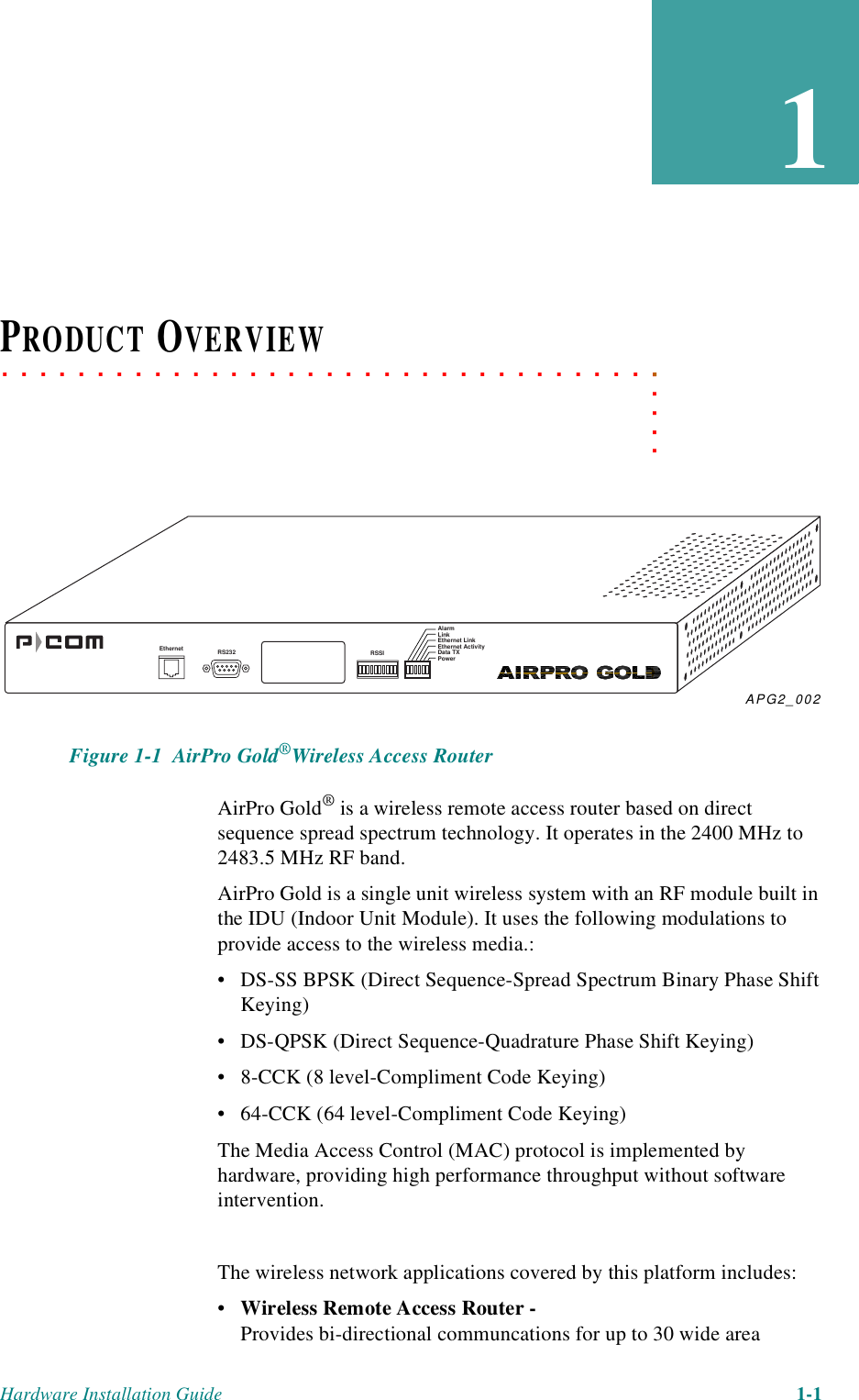
Wave Wireless APG20FNET Wireless LAN, AIRPRO GOLD 20F.NET User Manual PDM2
Wave Wireless Corporation Wireless LAN, AIRPRO GOLD 20F.NET PDM2
UserManual.wiki
>
Wave Wireless
>
APG20FNET User Manual
Manual
Navigation menu
Upload a User Manual
Namespaces
Wiki Guide
HTML
PDF
Info
Views
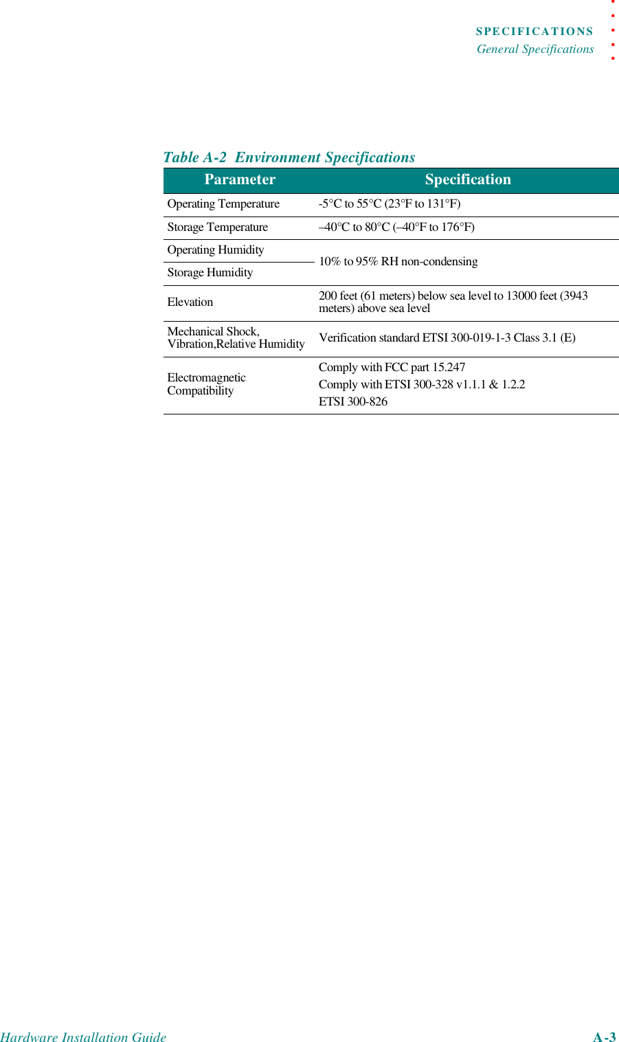
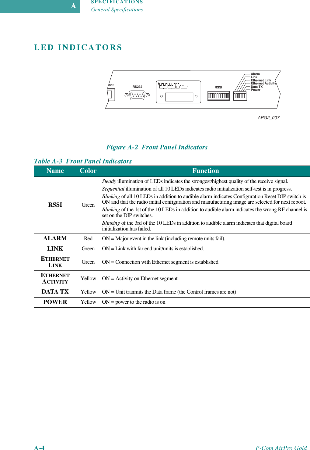
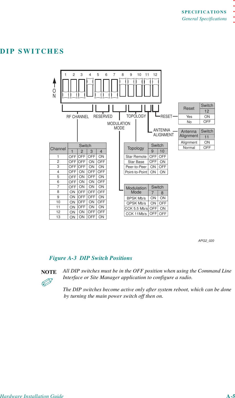
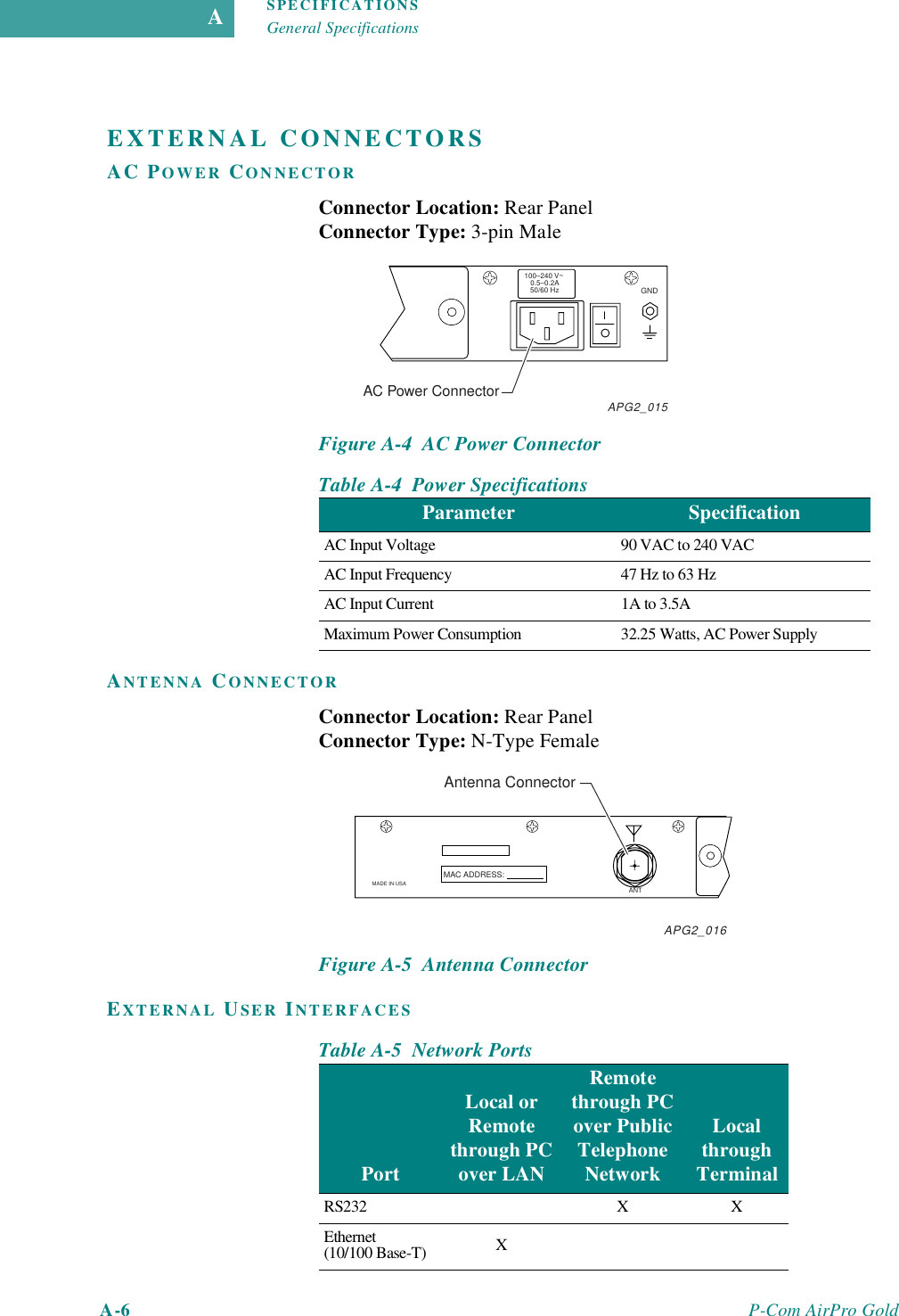
User Manual
Discussion / Help
Navigation