Wave Wireless APG20FNET Wireless LAN, AIRPRO GOLD 20F.NET User Manual PDM2
Wave Wireless Corporation Wireless LAN, AIRPRO GOLD 20F.NET PDM2
Manual
P–Com AirPro Gold
®
Wireless Router
Hardware Installation Guide

P-Com AirPro Gold®
Wireless Router
Hardware Installation Guide

© COPYRIGHT 2001 P-Com Inc. World Rights reserved.
P-Com Inc. provides this Installation Guide without warranty of any kind, either express or implied,
including, but not limited to, the implied warranties of merchantability and fitness for a particular
purpose.
P-Com Inc. may make improvements and changes to the product described in this manual at any time
and without any notice. P-Com Inc. assumes no responsibility for its use, nor any infringements of
patents or other rights of third parties that would result.
This publication may contain technical inaccuracies or typographical errors. Periodic changes are
made to the information contained herein. These changes, and mechanical corrections, will be
incorporated in subsequent revision levels of the publication.
No part of this publication may be stored in a retrieval system, transmitted, or reproduced in any way,
including but not limited to photocopy, photograph, magnetic or other records, without the prior
written permission of P-Com Inc.
AirPro Gold® is a trademark of P-Com Inc.
All other brand and product names are the trademarks of their respective holders.
P/N 32066-MNL Rev B
Jan 2002
STATEMENT OF WARRANTY
This product, except as stated otherwise in an applicable price list, is warranted against defects in workmanship
and material for a period of three (3) years from date of delivery as evidenced by the manufacturer’s packing
slip or other transportation receipt.
The manufacturer’s sole responsibility under this warranty shall be to either repair or replace, at its option, any
component which fails during the applicable warranty period because of a defect in workmanship and material,
provided PURCHASER has promptly reported same to the manufacturer in writing. All replaced Products or
parts shall become property of the manufacturer.
P-Com shall honor the warranty at its repair facility in Campbell, California. It is PURCHASER’s responsibility
to return, at its expense, the allegedly defective Product to the manufacturer. PURCHASER must obtain a
Return Materials Authorization (RMA) number and shipping instructions from the manufacturer prior to
returning any Product under warranty. Transportation charges for the return of the Product to PURCHASER
shall be paid by the manufacturer within the United States. For all other locations, the warranty excludes all
costs of shipping, customs clearance and other related charges. If the manufacturer determines that the Product
is not defective within the terms of the warranty, PURCHASER shall pay to the manufacturer all costs of
handling, transportation and repairs at the then prevailing repair rates.
All the above warranties are contingent upon proper use of the Product. These warranties will not apply (i) if
adjustment, repair or parts replacement is required because of accident, unusual physical, electrical or
electromagnetic stress, negligence of PURCHASER, misuse, failure of electric power, environmental controls,
transportation, not maintained in accordance with manufacturer’s specifications, or abuses other than ordinary
use (ii) if the Product has been modified by PURCHASER or has been repaired or altered outside the factory,
unless the manufacturer specifically authorizes such repairs or alterations; (iii) where manufacturer serial
numbers, warranty data or quality assurance decals have been removed or altered.
P-Com also reserves the right to make product improvements without incurring any obligation or liability to
make the same changes in Products previously manufactured or purchased. In no event shall the manufacturer
be liable for any breach of warranty in an amount exceeding the net selling price of any defective Product. No
person, including any dealer, agent or representative of P-Com is authorized to assume for P-Com any other
liability on its behalf except as set forth herein. Nonpayment of any invoice rendered within the stated payment
terms automatically cancels any warranty or guarantee stated or implied. If any payment is due to the
manufacturer for services performed hereunder, it shall be subject to the same payment terms as the original
purchase.
P-COM HEREBY DISCLAIMS ALL IMPLIED WARRANTIES ON PRODUCTS INCLUDING WITHOUT
LIMITATION, ALL IMPLIED WARRANTIES OF MERCHANTABILITY OR FITNESS FOR A
PARTICULAR PURPOSE. The warranties expressly stated herein are the sole obligation or liability on the part
of P-COM arising out of or in connection with the sale or performance of the products.
Products Manufactured by Others - For products not manufactured by P-COM, the original manufacturer’s
warranty shall be assigned to PURCHASER to the extent permitted and is in lieu of any other warranty, express
or implied. For warranty information on a specific product, a written request should be made to the
manufacturer.
IN NO EVENT WILL P-COM BE LIABLE TO PURCHASER FOR (i) REPROCUREMENT COSTS; (ii)
SPECIAL, INDIRECT OR CONSEQUENTIAL DAMAGES; (iii) ANY DAMAGES WHATSOEVER
RESULTING FROM LOSS OF USE, DATA OR PROFITS ARISING OUT OF OR IN CONNECTION WITH
THIS AGREEMENT, OR THE USE OR PERFORMANCE OF P-COM PRODUCTS, REGARDLESS OF
WHETHER THE CAUSE OF ACTION IS IN CONTRACT, TORT, INCLUDING NEGLIGENCE, OR ANY
OTHER FORM.
No action, whether in contract or tort, including negligence, arising out of or in connection with this Agreement,
may be brought by either party more than eighteen (18) months after the cause of action has accrued, except
that an action for nonpayment may be brought within eighteen (18) months of the date of last payment.

PRODUCT COMPATIBILITY
While every effort has been made to verify operation of this product with many different communications products and
networks, P-Com Corporation makes no claim of compatibility between its products and other vendors’ equipment. It is
assumed that users have thoroughly evaluated this product’s performance in the communications environment in which
it will be used.
SAFETY
The following general safety precautions must be observed during all phases of operation and service of this product.
Failure to comply with these precautions or with specific warnings elsewhere in this Manual willfully violates standards
of design, manufacture, and intended use of the product. P-Com Corporation assumes no liability for the customer’s
failure to comply with these requirements.
This product must be grounded. In the event of a short circuit, grounding reduces the risk of electrical shock by providing
an escape wire for the current.
We recommend that you use preferred power—a dedicated power circuit with an assigned circuit breaker.
The product’s AC power cord ends in a three-pole grounding plug. Do not use a three-pole to two-pole adapter with the
plug. Verify that the outlet you intend to use is properly installed and grounded; the outlet used must comply with the
National Electric Code (NEC) NFPA70 (1990) in U.S.A. or other local and national or international applicable code.
Do not install or operate this product in the presence of flammable gases or fumes. Operation of any electrical instrument
in such an environment constitutes a definite safety hazard.
No user maintained or adjustable components are present within this product. Do NOT attempt to open this unit. Do not
attempt to service this unit except under the direction of Customer Service. Only P-Com-authorized service personnel
should service this equipment. The potential for electrical shock exists within the enclosures at all times unless they are
unplugged.
Do not install substitute parts or perform any unauthorized modification to the product. Return the product to the factory
for service and repair to ensure that safety features are maintained. Prior to returning any product(s) for repair, contact P-
Com at the telephone numbers or address located in this Manual, and obtain a Return Material Authorization (RMA)
number.
Changes or modifications not expressly approved by P-Com Corporation can void the user’s authority to operate this
equipment.
SYSTEM GROUNDING
Direct grounding of the antenna, mast, and tower serves as protection from lightning strikes and static buildup. A direct
electrical connection should be made to a suitable grounding rod at the base of the tower or mast using at least #10 AWG
ground wire, or its equivalent, and non-corrosive hardware. For details and safety standards, consult the appropriate local
Electrical Codes or a similar document. Use lightning arresters in appropriate places.
TOWER CONSTRUCTION
Compliance with local zoning and tower construction regulations is recommended when AirPro Gold® systems require a
tower. These regulations generally mandate that permits be obtained before any tower construction begins. Check with
local zoning and aviation authorities for more information.

FCC NOTICE TO USERS
This device complies with Part 15.247. Assigned FCC Registration Number (FRN) is 0005-8888-70.
This equipment has been tested and found to comply with the limits for a class B device, pursuant to Part 15 of the FCC
Rules. These limits are designed to provide reasonable protection against harmful interference in a residential installation.
This equipment generates, uses and can radiate radio frequency energy and , if not installed and used in accordance with
the instructions, may cause harmful interference to radio communications. However, there is no guarantee that
interference will not occur in a particular installation. If this equipment does cause harmful interfernce to radio or
television reception, which can be determined by turning the equipment off and on, the user is encouraged to try to correct
the interference by one or more of the following measures:
- Reorient or relocate the receiving antenna.
- Increase the seperation between the equipment and receiver.
- Connect the equipment into an outlet on a circuit different from that to which the receiver is connected.
- Consult the dealer or an experinced radio/TV technician for help.
IN ACCORDANCE WITH FCC PART 15
OPERATION IS SUBJECT TO THE FOLLOWING CONDITIONS:
USER
1.) Professional installation required.
2.) The antenna(s) used for this transmitter must be fixed-mounted on outdoor permanent structures with a separation
distance of at least 2 meters from all persons and must not be co-located or operating in conjunctionwith any other antenna
or transmitter.
INSTALLER
1.) Professional installation required.
2.) The antenna(s) used for this transmitter must be fixed-mounted on outdoor permanent structures with a separation
distance of at least 2 meters from all persons and must not be co-located or operating in conjunction with any other antenna
or transmitter.
3.)The maximum peak outdoor power of the intentional radiator shall not exceed 1 watt (+30dBm). In addition, this
system operating in the 2400-2483.5 Mhz band may employ transmitting antennas with directional gain greater than 6
dBi provided the maximum peak outdoor power of the intentional radiator is reduced by 1 dB for every 3 dB that the
directional gain of the antenna exceeds 6dBi.
Product Output Power selection setting instructions:
a.) Connect a PC (serial port) to the unit’s front panel Computer Port. This port is a standard RS-232 inerconnection. (See
section A-7 of the installation manual)
b.)Configure Output Power setting via:
1.) Hyper-Terminal
- Baud Rate 115200
- Data Bits 8
- Parity None
- Stop Bits 1
- Flow Control Hardware
Establish a terminal session, at the Command Line Interface; enter Pwr and the Power Selection. Reboot the system by
entering BOOT, then ENTER. It is not necessary to power down the unit.
2.) P-Com’s proprietary installation software-Site Manager
See Site Manager instuction manual for Output Power Setting configuration.
ETSI NOTICE TO USERS
This device complies with ETSI 300-328 and ETSI 300-326 ETSI rules. Operation is subject to the following two
conditions:
(1) This device may not cause harmful interference, and
(2) This device may not cause any interference that may cause undesired operation.
Changes or modifications not expressly approved by P-Com Inc. can void the user’s authority to operate the equipment.
ETSI regulations require that this device be professionally installed by a person knowledgeable in electronics and trained
in the correct installation of this device.
All interface cables must be shielded.

Hardware Installation Guide viii
. . . . .
. . . . . . . . . . . . . . . . . . . . . . . . . . . . . . . . . . .
Contents
Before You Begin xvi
. . . . . . . . . . . . . . . . . . . . . . . . . . . . . . . . . . . . . . . . . . . . . . . . . .
Purpose of This Guide xvi
. . . . . . . . . . . . . . . . . . . . . . . . . . . . . . . . . . . . . . . . . . . . . . . . . .
Prior Knowledge xvi
. . . . . . . . . . . . . . . . . . . . . . . . . . . . . . . . . . . . . . . . . . . . . . . . . .
How This Guide is Organized xvi
. . . . . . . . . . . . . . . . . . . . . . . . . . . . . . . . . . . . . . . . . . . . . . . . . .
How to Use This Guide xvii
. . . . . . . . . . . . . . . . . . . . . . . . . . . . . . . . . . . . . . . . . . . . . . . . . .
Typographic Conventions xvii
. . . . . . . . . . . . . . . . . . . . . . . . . . . . . . . . . . . . . . . . . . . . . . . . . .
Customer Service xvii
E-mail Service xvii
Telephone and Fax Service xvii
Service and Repair Centers xviii
United States Service and Repair Center xviii
Brazil Service and Repair Center xviii
China Service and Repair Center xviii
India Service and Repair Center xviii
. . . . . . . . . . . . . . . . . . . . . . . . . . . . . . . . . . . . . . . . . . . . . . . . . .
Return Material Authorization (RMA) xix
. . . . . . . . . . . . . . . . . . . . . . . . . . . . . . . . . . . . . . . . . . . . . . . . . .
International Sales Offices xix
Chapter 1. Product Overview
. . . . . . . . . . . . . . . . . . . . . . . . . . . . . . . . . . . . . . . . . . . . . . . . . .
Product Description 1-3
Topologies 1-3
Front Panel 1-4
Rear Panel 1-5
. . . . . . . . . . . . . . . . . . . . . . . . . . . . . . . . . . . . . . . . . . . . . . . . . .
Product Features 1-5

CONTENTS
ix P-Com AirPro Gold
Chapter 2. Wireless Network Design
. . . . . . . . . . . . . . . . . . . . . . . . . . . . . . . . . . . . . . . . . . . . . . . . . .
Packet-Based Networks 2-1
. . . . . . . . . . . . . . . . . . . . . . . . . . . . . . . . . . . . . . . . . . . . . . . . . .
Point-to-Point Topology 2-2
. . . . . . . . . . . . . . . . . . . . . . . . . . . . . . . . . . . . . . . . . . . . . . . . . .
Peer-to-Peer Topology 2-2
. . . . . . . . . . . . . . . . . . . . . . . . . . . . . . . . . . . . . . . . . . . . . . . . . .
Centralized (Star) Topology 2-3
Chapter 3. Hardware Installation
. . . . . . . . . . . . . . . . . . . . . . . . . . . . . . . . . . . . . . . . . . . . . . . . . .
Wireless Router Installation 3-1
Ground Connection 3-1
LAN Connection 3-2
Antenna Connection 3-2
Antenna Alighment 3-3
Power Connection 3-3
. . . . . . . . . . . . . . . . . . . . . . . . . . . . . . . . . . . . . . . . . . . . . . . . . .
Telephone Modem Connection 3-4
. . . . . . . . . . . . . . . . . . . . . . . . . . . . . . . . . . . . . . . . . . . . . . . . . .
Basic Configuration Setup 3-5
DIP Switches 3-5
Command Line Interface 3-7
Site Manager Application 3-9
Chapter 4. Rack Mounting
. . . . . . . . . . . . . . . . . . . . . . . . . . . . . . . . . . . . . . . . . . . . . . . . . .
19 inch Rack Mount 4-2
. . . . . . . . . . . . . . . . . . . . . . . . . . . . . . . . . . . . . . . . . . . . . . . . . .
23 inch Rack Mount 4-3
Appendix A.Specifications
. . . . . . . . . . . . . . . . . . . . . . . . . . . . . . . . . . . . . . . . . . . . . . . . . .
General Specifications A-2
LED Indicators A-4

. . . . .
CONTENTS
Hardware Installation Guide x
DIP Switches A-5
External Connectors A-6
AC Power Connector A-6
Antenna Connector A-6
External User Interfaces A-6
RS232 Connector A-7
Ethernet Connector A-8
. . . . . . . . . . . . . . . . . . . . . . . . . . . . . . . . . . . . . . . . . . . . . . . . . .
Radio Specifications A-9
. . . . . . . . . . . . . . . . . . . . . . . . . . . . . . . . . . . . . . . . . . . . . . . . . .
Center Frequencies A-10
Index

CONTENTS
xi P-Com AirPro Gold

Hardware Installation Guide xii
. . . . .
. . . . . . . . . . . . . . . . . . . . . . . . . . . . . . . . . . .
List of Figures
Figure 1-1. AirPro Gold®Wireless Access Router 1-1
Figure 1-2. AirPro Gold Front Panel 1-4
Figure 1-3. AirPro Gold Rear Panel 1-5
Figure 2-1. Point-to-Point Topology 2-2
Figure 2-2. Peer-to-Peer Topology 2-3
Figure 2-3. Star Topology 2-4
Figure 3-1. Ground Wire on AirPro Gold Unit 3-2
Figure 3-2. ANT Connector 3-3
Figure 3-3. Telephone Modem Connection 3-4
Figure 3-4. DIP Switches 3-5
Figure 3-5. Connecting the Terminal or PC 3-7
Figure 3-6. Connecting the Power Cord 3-8
Figure 4-1. Rack Mounted Radios 4-1
Figure 4-2. Brackets for 19 inch Rack Mount 4-2
Figure 4-3. Brackets for 23 inch Rack Mount 4-3
Figure A-1. Radio Dimensions A-2
Figure A-2. Front Panel Indicators A-4
Figure A-3. DIP Switch Positions A-5
Figure A-4. AC Power Connector A-6
Figure A-5. Antenna Connector A-6
Figure A-6. RS-232 Connector A-7
Figure A-7. Ethernet Jack A-8

LIST OF FIGURES
xiii P-Com AirPro Gold

Hardware Installation Guide xiv
. . . . .
. . . . . . . . . . . . . . . . . . . . . . . . . . . . . . . . . . .
List of Tables
Table A. Customer Service Telephone Numbers xviii
Table B. International Sales Offices xix
Table 3-1. RF Channel Switch Positions 3-6
Table 3-2. Topology Switch Positions 3-6
Table A-1. Mechanical Specifications A-2
Table A-2. Environment Specifications A-3
Table A-3. Front Panel Indicators A-4
Table A-4. Power Specifications A-6
Table A-5. Network Ports A-6
Table A-6. RS-232 Port Pin Assignments A-7
Table A-7. Radio Specifications A-9
Table A-8. Transmitter Specifications A-9
Table A-9. Receiver Specifications A-10
Table A-10. RF Channel Center Frequencies A-10

LIST OF TABLES
xv P-Com AirPro Gold

Hardware Installation Guide xvi
. . . . .
. . . . . . . . . . . . . . . . . . . . . . . . . . . . . . . . . . .
Before You Begin
. . . . . . . . . . . . . . . . . . . . . . . . . . . . . . . . . . . . . . . . . . . . . . . . . .
PURPOSE OF THIS GUIDE
This P-Com AirPro Gold® Hardware Installation Guide is directed to
persons who must perform or coordinate the tasks associated with the
process of installing a AirPro Gold® wireless router in a local area
network (LAN).
. . . . . . . . . . . . . . . . . . . . . . . . . . . . . . . . . . . . . . . . . . . . . . . . . .
PRIOR KNOWLEDGE
This Installation Guide assumes that you are knowledgeable about basic
hardware installation concepts and practices. If you are not, the
information in this Installation Guide may be difficult for you to
understand and implement.
. . . . . . . . . . . . . . . . . . . . . . . . . . . . . . . . . . . . . . . . . . . . . . . . . .
HOW THIS GUIDE IS ORGANIZED
This Installation Guide is organized in chapters and appendix material
in the following manner:
• Chapter 1 - provides a product overview of the AirPro Gold wireless
router
• Chapter 2 - describes different wireless network topologies
• Chapter 3 - tells you how to perform a basic radio configuration and
hardware installation
• Chapter 4 - provides instructions for mounting the AirPro Gold in an
equipment rack
• Appendix A - provides AirPro Gold specifications
BEFORE YOU BEGIN
How to Use This Guide
xvii P-Com AirPro Gold
. . . . . . . . . . . . . . . . . . . . . . . . . . . . . . . . . . . . . . . . . . . . . . . . . .
HOW TO USE THIS GUIDE
Before beginning the installation process, review all the chapters so that
you have a sense of what each chapter provides. Verify that you have
selected the proper installation procedure to meet site-specific needs.
Read through an entire procedure before you begin performing the step-
by-step instructions. By doing this, you will be prepared with the
appropriate information, equipment, or tools.
. . . . . . . . . . . . . . . . . . . . . . . . . . . . . . . . . . . . . . . . . . . . . . . . . .
TYPOGRAPHIC CONVENTIONS
Notes, Cautions, and Warnings are shown as:
A note gives you information of special interest.
A caution gives you information that you need so that you will not damage the
equipment or lose data.
A warning gives you information that you need so that you do not cause harm to
yourself or any other person, and so that you do not damage or interfere with
the network application.
. . . . . . . . . . . . . . . . . . . . . . . . . . . . . . . . . . . . . . . . . . . . . . . . . .
CUSTOMER SERVICE
P-Com distributors are authorized local service providers and are
responsible for immediate customer support. If problems are not
resolved, you can contact P-Com Customer Service for assistance.
E-MAIL SERVICE
P-Com Customer Service provides the following e-mail address for
customer assistance:
customer_service@p-com.com
TELEPHONE AND FAX SERVICE
P-Com Customer Service maintains a 24-hour answering service for
emergency telephone support. Customer Service responses to
emergency calls consist of over-the-phone troubleshooting and
assistance in obtaining distributor support.
See Table A for Customer Service telephone numbers.
NOTE
✐

. . . . .
BEFORE YOU BEGIN
Customer Service
Hardware Installation Guide xviii
SERVICE AND REPAIR CENTERS
Service and repair centers are located in the United States, Brazil, China,
and India.
UNITED STATES SERVICE AND REPAIR CENTER
Address: Telephone and fax:
P-Com, Inc. 1.408.866.3666
3175 S. Winchester Blvd. 1.408.866.3161 (fax)
Campbell CA 95008 USA
BRAZIL SERVICE AND REPAIR CENTER
Address: Telephone and fax:
Mapra 55.11.3861.5036
Rue Caio Graco, 798-lapa 55.11.3861.5031 (fax)
CEP 05044-000 Sao Paulo
CHINA SERVICE AND REPAIR CENTER
Address: Telephone and fax:
Airlink Wireless 86.10.6467.1905
Room 227, Towercrest Place 86.10.6467.1906 (fax)
No. 3 Mai Zi Dian Xi Road
Beijing 100016 PRC
INDIA SERVICE AND REPAIR CENTER
Address: Telephone and fax:
P-Com India 91.1246.3646.14/15/16
A27/4 91.1246.3587.43 (fax)
DLF QUTAB Enclave-I
Gurgoan 122002 India
Table A Customer Service Telephone Numbers
If you are in this location Call this number
Within the USA 1-800-500-PCOM
United Kingdom 44.1527.62229
Singapore 65.223.6883
China 86.10.6467.1905
India 91.1246.3646.14/15/16
Pakistan 9221.582.2401
Any other country outside the USA 1-408-866-3666

BEFORE YOU BEGIN
Return Material Authorization (RMA)
xix P-Com AirPro Gold
RETURN MATERIAL AUTHORIZATION
. . . . . . . . . . . . . . . . . . . . . . . . . . . . . . . . . . . . . . . . . . . . . . . . . .
(RMA)
Before you return equipment to a Service/Repair Center, you need a
Return Material Authorization (RMA) number.
To get the RMA number:
1Gather the following information:
• unit model number
• unit serial number
• address to where unit was sold, billed, or shipped
• purchase order number (if unit not under warranty)
• whether credit or service is required
• description of unit failure (no sync, no output, etc.)
2From within the USA, call Customer Service at 1-800-500-PCOM
From outside the USA, call Customer Service at 408-866-3666, or contact one
of the Service and Repair centers (see page xv).
3Provide Customer Service with the information gathered in Step 1.
When returning equipment, be sure to write the RMA number on the outside of
the shipping carton.
. . . . . . . . . . . . . . . . . . . . . . . . . . . . . . . . . . . . . . . . . . . . . . . . . .
INTERNATIONAL SALES OFFICES
P-Com, Inc. international sales offices are located throughout the world.
See Table B.
Table B International Sales Offices
Country Telephone FAX
United Kingdom 44.1527.62229 44.1527.66436
Singapore 65.223.6883 65.223.6228
China 86.10.6467.1905 86.10.6467.1906
India 91.1246.3646.14/15/16 91.1246.358743
Pakistan 9221.582.2401 9221.583.8724
Russia 7095.182.45.03 7095.182.68.15
Latin America 408.866.3666 408.874.4205
Dubai 971.4.394.7810 971.4.394.7812
NOTE
✐
Hardware Installation Guide 1-1
1
. . . . .
. . . . . . . . . . . . . . . . . . . . . . . . . . . . . . . . . . .
P
RODUCT
O
VERVIEW
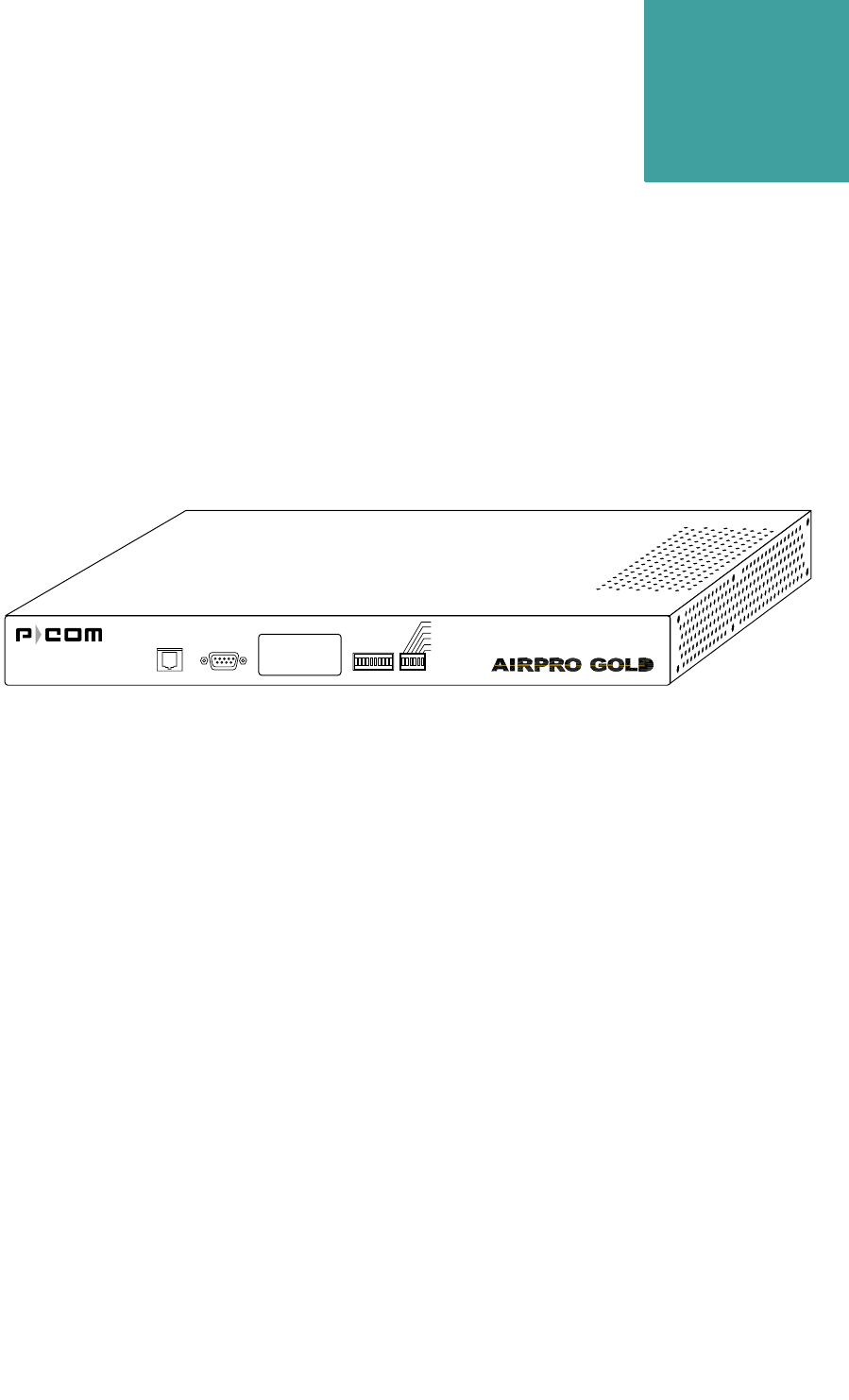
Figure 1-1 AirPro Gold®Wireless Access Router
AirPro Gold® is a wireless remote access router based on direct
sequence spread spectrum technology. It operates in the 2400 MHz to
2483.5 MHz RF band.
AirPro Gold is a single unit wireless system with an RF module built in
the IDU (Indoor Unit Module). It uses the following modulations to
provide access to the wireless media.:
• DS-SS BPSK (Direct Sequence-Spread Spectrum Binary Phase Shift
Keying)
• DS-QPSK (Direct Sequence-Quadrature Phase Shift Keying)
• 8-CCK (8 level-Compliment Code Keying)
• 64-CCK (64 level-Compliment Code Keying)
The Media Access Control (MAC) protocol is implemented by
hardware, providing high performance throughput without software
intervention.
The wireless network applications covered by this platform includes:
•Wireless Remote Access Router -
Provides bi-directional communcations for up to 30 wide area
APG2_002
Ethernet RS232 RSSI
Alarm
Link
Ethernet Link
Ethernet Activity
Data TX
Power

PRODUCT OVERVIEW
1-2 P-Com AirPro Gold
1
Network (WAN) nodes with minimum assigned data for each node
equal to 9.6 kbps. Each remote node provides wireless extension for
Ethernet 10/100 Based-T.
The AirPro Gold platform provides advanced network management
features using SNMP and HTTP protocols for control and monitoring,
supports remote configuration by means of BOOT/DHCP (Dynamic
Host Configuration Protocol) along with TFTP (Trivial File
Transferring Protocol) for downloading .

. . . . .
PRODUCT OVERVIEW
Product Description
Hardware Installation Guide 1-3
. . . . . . . . . . . . . . . . . . . . . . . . . . . . . . . . . . . . . . . . . . . . . . . . . .
PRODUCT DESCRIPTION
AirPro Gold is easy to install and configure. All software controls are
included for network administration. Initial configuration is
implemented via
• a switch bank of twelve DIP switches, or
• a Command Line Interface running on a terminal, or
• the Site Manager application running on a PC connected to the AirPro
Gold unit through a local area network (LAN) or through the public
telephone network
AirPro Gold offers wide area network connectivity when cables cannot
be used due to distance, physical obstructions, or price constraints. The
wireless network can be dynamically reconfigured to provide new
permanent or temporary services. Adding or removing nodes does not
affect network operation.
AirPro Gold lowers networking costs by combining routing and wireless
transceiver functions in a single unit. It provides remote downloading of
firmware and provides password and hard-coded serial number
protected management. The Ethernet 10/100 base-T port connects to the
LAN.
TOPOLOGIES
AirPro Gold provides bi-directional communication for multiple WAN
nodes. The wireless network can be configured to one of three network
topologies:
• Point-to-point—where two nodes are communicating directly with
each other (see section Point-to-Point Topology on page 2-1)
• Peer-to-peer—where all nodes in a network communicate directly
with one another (see section Peer-to-Peer Topology on page 2-2)
• Centralized (Star base)—where the node at the center of the network
acts as a switching device for communication between remote nodes
(see section Centralized (Star) Topology on page 2-3)
• Centralized (Star remote)—for remote stations in centralized
topology.Star remote can send the Data frame only when it gets the
permission from Star base.(see section Centralized (Star) Topology
on page 2-3)

PRODUCT OVERVIEW
Product Description
1-4 P-Com AirPro Gold
1
FRONT PANEL
Figure 1-2 AirPro Gold Front Panel
The AirPro Gold front panel (see Figure 1-2) includes:
➀ETHERNET—RJ-45 jack for Ethernet connection (10/100 base-T);
illuminated green LED indicates unit sees Ethernet connection, OFF
indicates no connection; illuminated yellow LED indicates no traffic on
the Ethernet bus, flashing indicates traffic on the bus
➁RS232—RS-232 port for direct connection to a terminal or external
telephone modem
➂DIP SWITCHES—12 up/down (ON/OFF) toggle switches for manual
RF configuration (under removable metal plate)
➃RSSI—7-element LED bar that illuminates during normal operation
to indicate the quality of the receive signal; sequential illumination of
each LED during startup indicates that the initialization self-test is in
progress; no illumination of the LEDs at the end of startup indicates
successful completion of self-test
➄Front Panel LED Indicators
ALARM—Red LED illuminates when major events in the link
(including remote units fail).
LINK— Green LED illuminates when the link with the far end unit/units
is established.
ETHERNET LINK—Green LED illuminates when the unit indicates
that connection with the Ethernet segment is established.
ETHERNET ACTIVITY—Yellow LED illuminates when there is
activity with the Ethernet segment.
DATA TX—Yellow LED illuminates when the unit transmits the Data
frame (the Control frames are not indicated).
POWER—Yellow LED illuminates when unit power is ON.
Ethernet RS232 RSSI
Alarm
Link
Ethernet Link
Ethernet Activity
Data TX
Power
1 2 3 4 5
APG2_008
. . . . .
PRODUCT OVERVIEW
Product Features
Hardware Installation Guide 1-5
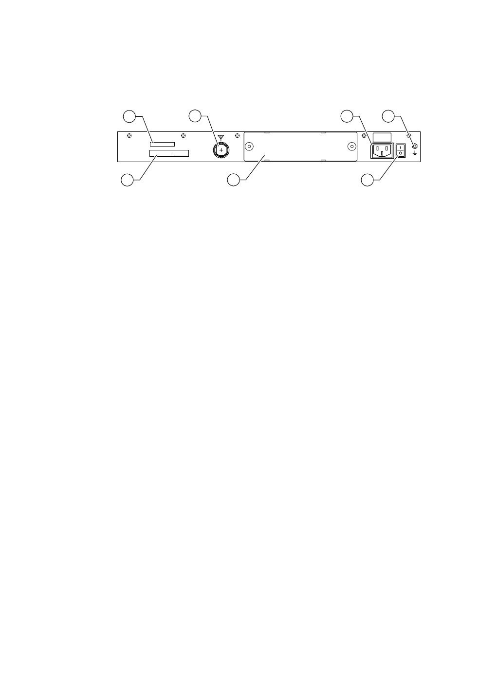
REAR PANEL
Figure 1-3 AirPro Gold Rear Panel
The AirPro Gold rear panel (see Figure 1-3) includes:
➀Regulatory label
➁MAC Address Label
➂ANT— Connector for the antenna.
➃I/O MODULE—I/O slot supports different data interfaces.
➄AC Power cord connector— For AC power cord
➅AC power ON/OFF rocker switch
➆GND—Grounding stud
. . . . . . . . . . . . . . . . . . . . . . . . . . . . . . . . . . . . . . . . . . . . . . . . . .
PRODUCT FEATURES
AirPro Gold interconnects computer LANs at geographically dispersed
offices, warehouses, and other sites. Using robust spread spectrum
technology that resists noise and interference, AirPro Gold can be
deployed quickly, since no license is required in many countries. Where
wired WAN solutions are costly or not available, AirPro Gold provides a
solution to support geographically dispersed enterprises and network
service providers.
MADE IN USA MAC ADDRESS:
ANT
GND
100–240 V~
0.5–0.2A
50/60 Hz
APG2_010
1
2
3
46
5 7

PRODUCT OVERVIEW
Product Features
1-6 P-Com AirPro Gold
1
FEATURES AND BENEFITS
Features Benefits
Wireless solution
Works where wired connectivity is not available or
practical; one-time capital expense; no ongoing
service charges, cost competitive with wired-WAN
services
Router functionality; network layer IP
routing
Interconnects networks at dispersed sites over a
wide area; maintains independent networks on the
WAN
2.4 GHz spread spectrum transmission; Robust, reliable, secure; resists noise and
interference; unlicensed operation in most
countries
Wired WAN-like data throughput;
approaches T1 performance Faster performance than POTS, X.25, ISDN
Range to 50 km (30 miles) per hop;
supports multiple hops Covers metropolitan, suburban, rural, and isolated
areas
User-selectable physical topologies (star,
peer-to-peer, point-to-point) Flexibility in WAN design
Ethernet and antenna ports Fully self-contained wireless router
DIP switches for initial RF setup Field-ready for configuration download through
Windows-based Site Manager application
RJ-45 connector For Ethernet 10/100 base-T
RS-232 connector For direct connection to PC terminal or remote
connection to Site Manager over public telephone
network
Internal computing engine Fully self-contained
End-to-end SNMP support Monitor network and radio performance remotely
Selectable transmitter output power From -4 dBm to 26dBm
Remote test utilities Full management and control of network
Support for TCP/IP Provides flexibility
Support for RIP v1/v2 IP, Provides automated method of updating of the
network reachability information
Support for SNMP, TFTP and
BOOTP/DHCP protocols Provides complete network management
Unique Ethernet interface MAC address
and cluster ID Password protection for application level protocols

Hardware Installation Guide 2-1
2
. . . . .
. . . . . . . . . . . . . . . . . . . . . . . . . . . . . . . . . . .
W
IRELESS
N
ETWORK
D
ESIGN
The term network topology refers to the logical layout of a network. It
defines how the network elements will communicate with each other,
how the information will be transmitted, and how the information will
be routed through the network.
. . . . . . . . . . . . . . . . . . . . . . . . . . . . . . . . . . . . . . . . . . . . . . . . . .
PACKET-BASED NETWORKS
Packet-based networks are most suitable for networks that involve large-
scale data transmissions for multiple users at the same time. There is a
guaranteed minimum throughput for a packet-based network, but the
actual throughput realized by a packet-based network node will depend
on
• the number of users in the network, and
• how much traffic is being generated by each node at any given time
The advantage of a packet-based network is that multiple transmissions
can travel along the network at the same time, using whatever path is
appropriate to the routing from the source to the destination.
The most significant characteristic of packet-based networks is the
wireless interface access protocols they use, such as CSMA/CA (Carrier
Sense Multiple Access/Collision Avoidance), which can result in more
efficient use of the aggregate bandwidth by dynamically allocating
throughput to nodes based on demand.
AirPro Gold® supports Point-to-Point, Peer-to-Peer, and Centralized
(Star) packet-based network topologies. Each topology has its own
optimized wireless protocol.
. . . . . . . . . . . . . . . . . . . . . . . . . . . . . . . . . . . . . . . . . . . . . . . . . .
POINT-TO-POINT TOPOLOGY
In a packet-based point-to-point topology, two nodes are linked directly.
The most common application for this topology is the interconnection of

WIRELESS NETWORK DESIGN
Peer-to-Peer Topology
2-2 P-Com AirPro Gold
2
two LANs. In Figure 2-1, the LANs are connected via a pair of AirPro
Gold wireless routers.
Figure 2-1 Point-to-Point Topology
The range and interference immunity that can be achieved with packet-
based point-to-point topology is maximized by the use of highly
directional antennas on both sides of the link.
. . . . . . . . . . . . . . . . . . . . . . . . . . . . . . . . . . . . . . . . . . . . . . . . . .
PEER-TO-PEER TOPOLOGY
In peer-to-peer topology (unique to packet-based networks), there are
three or more nodes, any one of which can communicate directly with
any other node. Since each node has direct access to every other node,
the time delay for transferring data between nodes is the least for this
type of topology, unless WAN traffic is very high. However, this also
implies that each node must have a clear communication path to every
other node, that is, there must be clear line of sight.
An example of a three node peer-to-peer topology is shown in Figure 2-
2 on page 2-3.
APG1_002
Ethernet Ethernet
Ethernet RS232 RSQ/RSSI
Alarm
Link
Frame TX
Ethernet Link
Ethernet Activity
Power Ethernet RS232 RSQ/RSSI
Alarm
Link
Frame TX
Ethernet Link
Ethernet Activity
Power
. . . . .
WIRELESS NETWORK DESIGN
Centralized (Star) Topology
Hardware Installation Guide 2-3
Figure 2-2 Peer-to-Peer Topology
In peer-to-peer topology, since all nodes need to talk to each other, the
range depends on the type of antennas used and the local terrain. Longer
ranges can be achieved by using directional antennas with power
splitters to connect to all sites.
. . . . . . . . . . . . . . . . . . . . . . . . . . . . . . . . . . . . . . . . . . . . . . . . . .
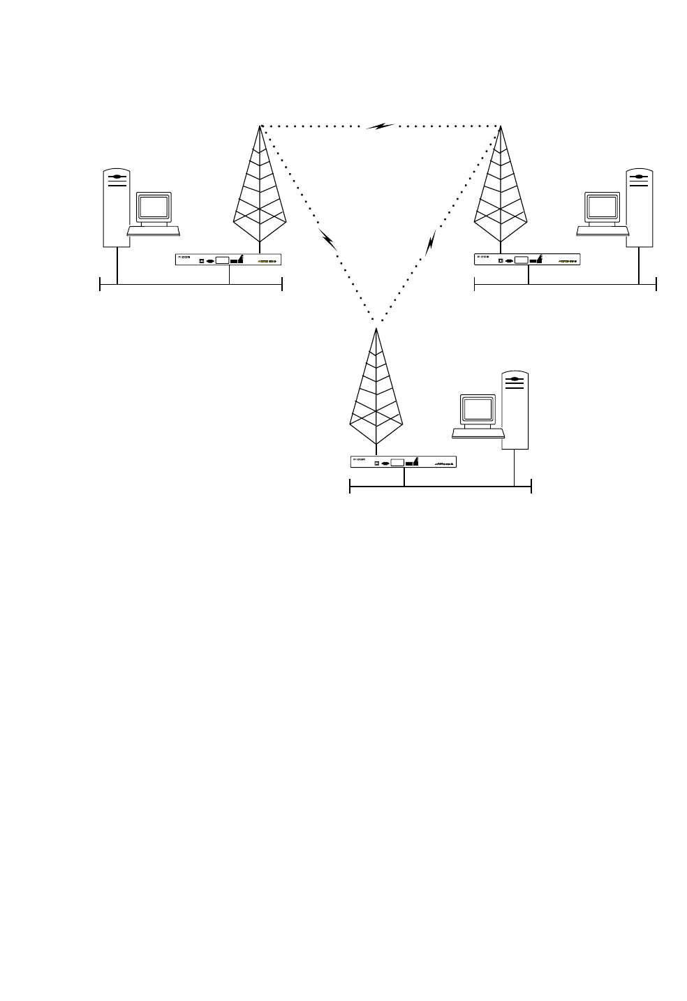
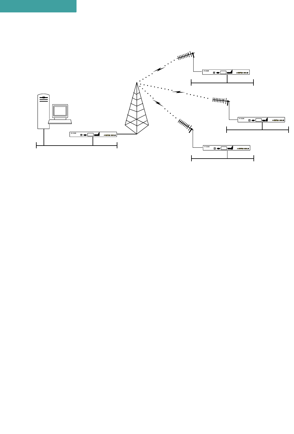
CENTRALIZED (STAR) TOPOLOGY
In a Star topology, there is one AirPro Gold at a central location
designated as a Base Station or Star Base, and several remotes
designated as Remote Stations or Star Remotes. The Star Base acts as a
switching device. The Star Remotes communicate with each other
through the Star Base.
An AirPro Gold wireless network with Star topology can connect up to
255 wireless nodes. The MAC protocol used combines random and
polling MAC protocols, with positive Data Link acknowledgment that
improves the reliability of frame delivery.
Figure 2-3 on page 2-4 shows AirPro Gold wireless router nodes in a
star topology.
Ethernet Ethernet
APG1_003
Ethernet
Ethernet RS232 RSQ/RSSI
Alarm
Link
Frame TX
Ethernet Link
Ethernet Activity
Power
Ethernet RS232 RSQ/RSSI
Alarm
Link
Frame TX
Ethernet Link
Ethernet Activity
Power
Ethernet RS232 RSQ/RSSI
Alarm
Link
Frame TX
Ethernet Link
Ethernet Activity
Power
WIRELESS NETWORK DESIGN
Centralized (Star) Topology
2-4 P-Com AirPro Gold
2
Figure 2-3 Star Topology
A directional antenna can be used for the central site if all of the nodes
fall in the main lobe of the antenna pattern. Since the remote sites need
only communicate with the central site, directional, high gain antennas
can be used.
The range of a Star topology network can be increased if the remote
nodes are all located within a confined sector from the central site.
Communication between two remote sites must be relayed through the
central node.
Medium access contention on the Star Base is resolved by the specific
Star Base MAC protocol. Each Star Remote sends a data frame only
after it gets permission from the Star Base. Each frame transmitted by
Star Base contains a PID (polling ID) for the wireless cluster. If a polled
Star Remote has a frame to transmit, it explicitly sends the frame to the
Star Base. The Star Base relays this frame to itself or on to Star
Remotes indicated by the DID (destination ID) of the original frame. A
polled Star Remote does not reply to a PID if it has no frame to transmit.
APG1_001
BASE STATION REMOTE STATIONS
Ethernet
Ethernet
Ethernet
Ethernet
Ethernet RS232 RSQ/RSSI
Alarm
Link
Frame TX
Ethernet Link
Ethernet Activity
Power
Ethernet RS232 RSQ/RSSI
Alarm
Link
Frame TX
Ethernet Link
Ethernet Activity
Power
Ethernet RS232 RSQ/RSSI
Alarm
Link
Frame TX
Ethernet Link
Ethernet Activity
Power
Ethernet RS232 RSQ/RSSI
Alarm
Link
Frame TX
Ethernet Link
Ethernet Activity
Power

Hardware Installation Guide 3-1
3
. . . . .
. . . . . . . . . . . . . . . . . . . . . . . . . . . . . . . . . . .
H
ARDWARE
I
NSTALLATION
At each wireless node, the AirPro Gold® unit connects to a LAN, where
it functions as a wireless remote access router, connecting LANs
through the wireless WAN (wide area network).
Each radio is shipped in a carton that contains:
• one P-Com AirPro Gold wireless router
• 0 dbi test antenna
• AC power cord
• mounting brackets and hardware for optional rack mounting
•Site Manager application software
• P-Com AirPro Gold Installation Guide
• P-Com AirPro Gold Site Manager Reference
After unpacking the shipping carton:
1Compare the materials in the shipping carton with items listed on the packing
list to make sure that you have received everything. If something is not included
in the shipping carton, or if there is shipping damage, contact the distributor.
2Save the shipping cartons and packing materials. You may need them if you
locate the equipment elsewhere.
. . . . . . . . . . . . . . . . . . . . . . . . . . . . . . . . . . . . . . . . . . . . . . . . . .
WIRELESS ROUTER INSTALLATION
Before you can install the AirPro Gold unit in the network, you must
provide power for the unit by connecting the AC power cord. Before
making any cable connections, however, you need to properly ground
the unit.
GROUND CONNECTION
The P-Com AirPro Gold unit should be grounded at the ground nut on the back
of the unit before you connect any other cables. After the unit is grounded,
make sure that any other equipment that you connect to the unit is also
properly grounded.

HARDWARE INSTALLATION
Wireless Router Installation
3-2 P-Com AirPro Gold
3
To ground the AirPro Gold unit:
1Loosen the GND nut on the back of the unit.
2Attach a #12 AWG minimum wire from the grounding stud to a safe ground.
See Figure 3-1 on page 3-2.
Figure 3-1 Ground Wire on AirPro Gold Unit
LAN CONNECTION
To connect the AirPro Gold to the LAN:
1Plug one end of an RJ-45 cable into the RJ-45 ETHERNET port on the front of
the unit.
2Plug the other end of the RJ-45 cable into the RJ-45 port on the Ethernet Hub.
If you are connecting the unit directly to a PC via the RJ-45 port, use a cross-
over cable (not a straight-through cable), plug one end into the RJ-45 port on
the AirPro Gold unit and the other end into the RJ-45 port of the Ethernet card
on the PC.
ANTENNA CONNECTION
The type of antenna you use should be a semi-parabolic or solid
parabolic directional antenna. You can purchase the antenna from P-
Com or its distributors.
APG2_013
Ground Wire
GND
100–240 V~
0.5–0.2A
50/60 Hz
NOTE
✐
. . . . .
HARDWARE INSTALLATION
Wireless Router Installation
Hardware Installation Guide 3-3
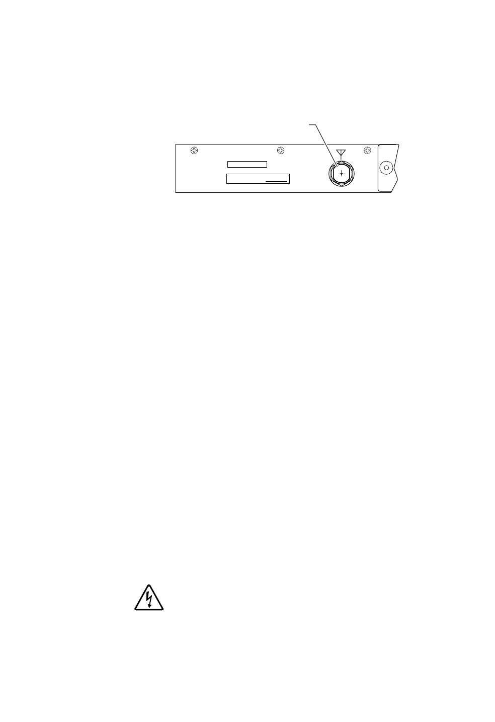
The indoor antenna connects to the rear of the AirPro Gold unit through
the N-type connector labeled ANT on the back of the radio. See
Figure 3-2. The outdoor antenna is connected through coaxial cable.
Figure 3-2 ANT Connector
To connect an indoor antenna to the AirPro Gold unit:
1Plug the antenna connector firmly into the N-type antenna connector on the
back of the unit.
2Hand-tighten the connector shell onto the jack connector collar.
3Verify that the connector is fixed firmly in place.
To connect an outdoor antenna to the AirPro Gold unit:
1Plug the coaxial antenna cable into the N-type antenna connector on the back of
the unit, making sure there are no sharp bends in the cable.
• Install the coaxial cable between the radio and antenna location, making sure
there are no sharp bends in the cable.
2Hand-tighten the connector shell onto the jack connector collar.
3Verify that the cable is fixed firmly in place.
If the antenna coaxial cable is too stiff to bend easily, add a flexible pigtail
coaxial cable with a coax barrel (available from P-Com).
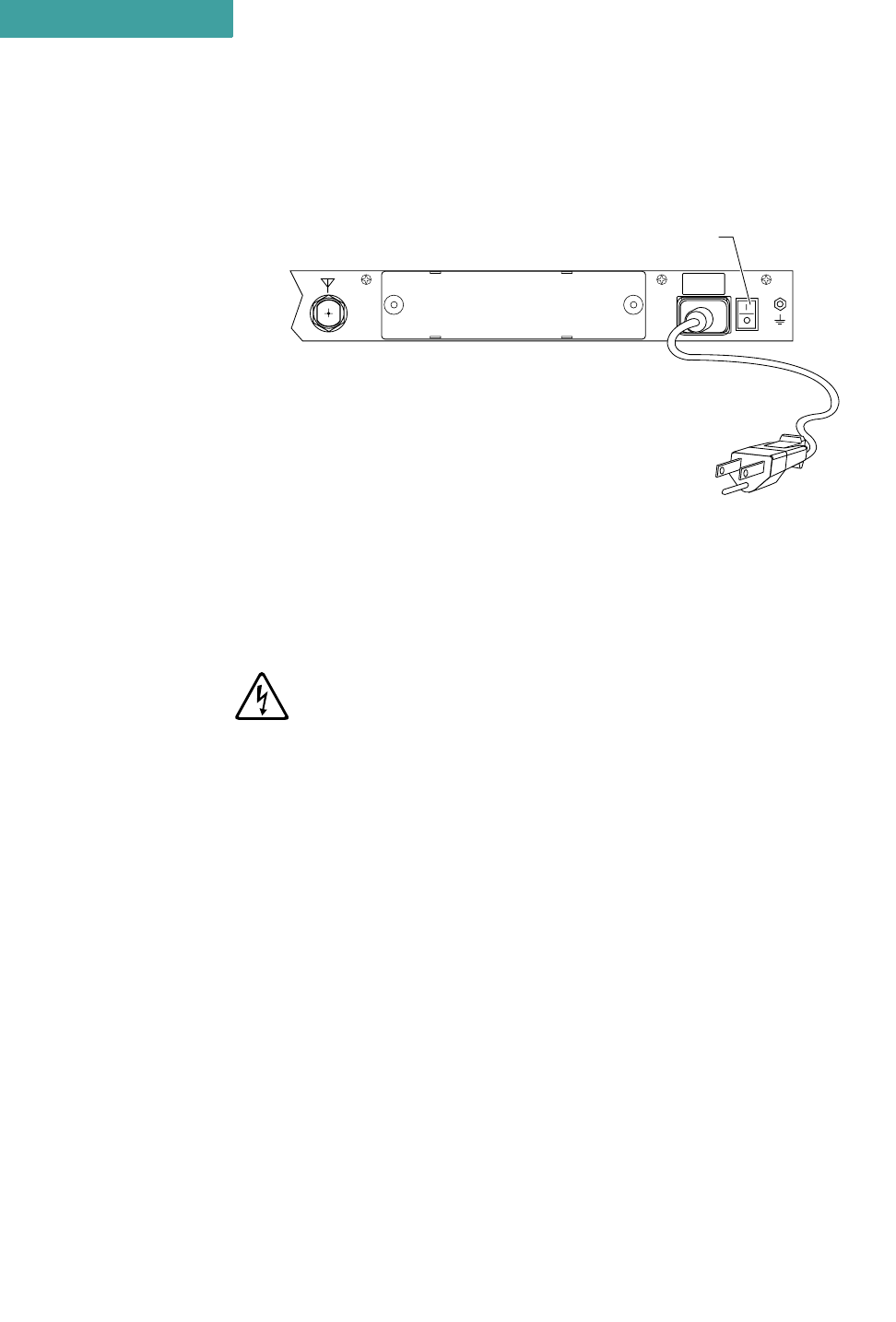
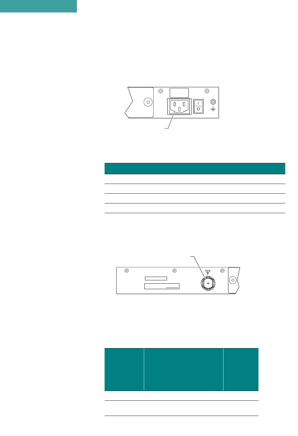
POWER CONNECTION
To connect power to the AirPro Gold unit:
1Plug the AC power cord into the 3-pin connector on the back of the unit. See
Figure 3-6 on page 3-8
2Plug the AC power cord into a grounded electrical outlet.
To avoid electrical shock or power loss, make sure that the power cord is
securely connected to the unit. Do not use a 3-pole to 2-pole adapter with the
plug. Verify that the outlet you use is properly installed, grounded, and
complies with the local electrical code.
3Turn the AC power switch to ON. See Figure 3-6 on page 3-8.
APG2_016
MADE IN USA MAC ADDRESS:
ANT
Antenna Connector
NOTE
✐
HARDWARE INSTALLATION
Telephone Modem Connection
3-4 P-Com AirPro Gold
3
. . . . . . . . . . . . . . . . . . . . . . . . . . . . . . . . . . . . . . . . . . . . . . . . . .
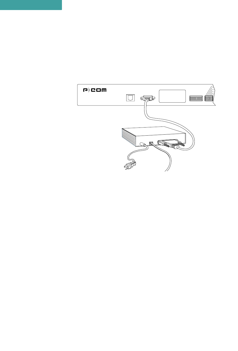
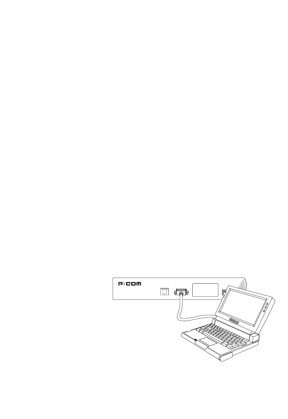
TELEPHONE MODEM CONNECTION
You can configure the P-Com AirPro Gold wireless router remotely by
using a telephone modem and the public telephone network. The AirPro
Gold provides an RS-232 port on the front of the unit for the modem
connection. See Figure 3-3 on page 3-4.
Figure 3-3 Telephone Modem Connection
Telephone modems should be 9600 bps or faster Hayes compatible
modems. Refer to the modem documentation for the specific baud rate,
and for modem configuration parameters.
To connect the telephone modem:
1Use a standard RS-232 modem cable, with a female DB-9 connector at the
AirPro Gold end and an appropriate connector at the modem end.
2Connect the telephone modem to the MODEM port on the back of the AirPro
Gold unit. See Figure 3-3.
3Connect the telephone modem to the phone line using an appropriate cable.
4Connect the computer or terminal to the telephone modem using a standard RS-
232 modem cable.
. . . . . . . . . . . . . . . . . . . . . . . . . . . . . . . . . . . . . . . . . . . . . . . . . .
BASIC CONFIGURATION SETUP
Before you use a AirPro Gold unit on the WAN, P-Com recommends
that you set up a basic unit configuration to make sure the full WAN
installation will proceed smoothly.
The basic configuration requires
Ethernet RS232 RSQ/RSSI
Telephone Modem
Phone Line
Power Supply
APG2_014
. . . . .
HARDWARE INSTALLATION
Basic Configuration Setup
Hardware Installation Guide 3-5
• RF channel—all units in a common network must use the same RF
channel. Separate WANs in the same geographic area may need to
use different channels (to eliminate interference). AirPro Gold
provides 13 channels.
• Topology—AirPro Gold provides these topologies: peer-to-peer,
point-to-point, centralized (star base and star remote)
• Configuration Reset—to install the basic configuration
You can set up a basic radio configuration using one of three methods:
• through DIP switch positions
• through a terminal command line interface
• through the Site Manager software application
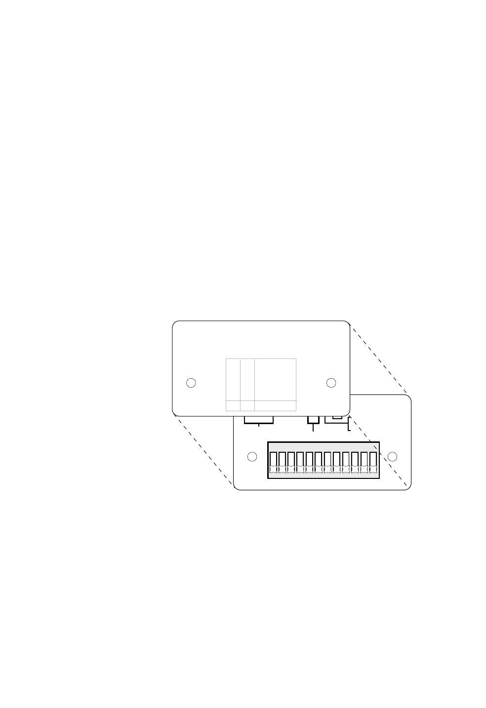
DIP SWITCHES
AirPro Gold can be configured through a block of twelve OFF/ON DIP
switches located on the front of the unit behind the switch plate. See
Figure 3-4.
Figure 3-4 DIP Switches
• To set the switch to the ON position, push the switch up toward the top of the
unit.
• To set the switch to the OFF position, push the switch down toward the bottom
of the unit.
To set up a basic unit configuration using the DIP switches:
1Remove the unit from the shipping carton.
2Place the unit on a flat surface so that the front is easy to reach.
APG2_022
123456789101112
O
N
ON-CONFIGURATION RESET
RF CHANNEL SEE COVER LABEL
ON-ANTENNA ALIGNMENT
MODE
OFF-NORMAL MODE
1
1
2
2
34
4
5678
812
48
9101112
RF CHANNEL MUST BE SELECTED USING
BINARY FORMAT (1 - ON, 0 - OFF)
TO CONFIGURE BY SOFTWARE OR TERMINAL ALL 12
SWITCHES MUST BE OFF
STAR REMOTE
STAR BASE
PEER-TO-PEER
POINT-TO-POINT
TOPOLOGY
ON
OFF
ON
OFF
ON
ON
OFF
OFF
109

HARDWARE INSTALLATION
Basic Configuration Setup
3-6 P-Com AirPro Gold
3
3Remove the switch plate from the front of the unit.
Set the RF channel switches according to Table 3-1..
Set the topology according to Table 3-2.
4Set Switch 11—Antenna Alignment to OFF.
5Set Switch 12—Reset Network Configuration to OFF.
When you move the AirPro Gold unit from one network to another, you will
need to reset the moved unit’s configuration by setting switch 12 to ON.
ANTENNA ALIGNMENT
Using the DIP switches on the front of the AirPro Gold unit, you can
start the antenna alignment utility to align a Star Remote unit antenna.
Table 3-1 RF Channel Switch Positions (20 MHz)
Channel
Center
Frequency Switch
(MHz) 1234
1 2411.000 OFF OFF OFF ON
2 2416.000 OFF OFF ON OFF
3 2421.000 OFF OFF ON ON
4 2426.000 OFF ON OFF OFF
5 2431.000 OFF ON OFF ON
6 2436.000 OFF ON ON OFF
7 2441.000 OFF ON ON ON
8 2446.000 ON OFF OFF OFF
9 2451.000 ON OFF OFF ON
10 2456.000 ON OFF ON OFF
11 2461.000 ON OFF ON ON
12 2466.000 ON ON OFF OFF
13 2471.000 ON ON OFF ON
Table 3-2 Topology Switch Positions
Switch
Topology 910
Star Remote OFF OFF
Star Base OFF ON
Peer-to-Peer ON OFF
Point-to-Point OFF ON
NOTE
✐
. . . . .
HARDWARE INSTALLATION
Basic Configuration Setup
Hardware Installation Guide 3-7
See the Site Manager Reference, Chapter 8, for instructions on antenna
alignment.
COMMAND LINE INTERFACE
AirPro Gold can be configured through a command line interface
running on a terminal (or a PC running a terminal emulation program).
Before connecting the terminal to a AirPro Gold unit, configure the
terminal with the following settings:
• Baud rate = 115200 bps
• Data bits = 8
• Parity = None
• Stop bits = 1
• Flow control = Hardware
If you are using a PC or laptop computer, refer to the operating system
documentation for instructions on how to configure and run the terminal
emulation program.
To set up a basic unit configuration using the command line interface:
1Remove the unit from the shipping carton.
2Remove the switch plate from the front of the unit. See Figure 3-4 on page 3-5.
3Make sure ALL the DIP switches are in the OFF position. This is the
manufacturing default.
• To set the switch to the OFF position, push the switch down toward the bottom
of the unit.
4Connect the terminal or PC to the RS232 port on the front of the unit. See
Figure 3-5 on page 3-7.
• Use a crossover (null modem) cable with a DB-9 male connector on one end to
connect to the unit, and an appropriate connector at the computer end.
Figure 3-5 Connecting the Terminal or PC
5Turn on the terminal.
Ethernet RS232 RSQ/RSSI
APG2_011
HARDWARE INSTALLATION
Basic Configuration Setup
3-8 P-Com AirPro Gold
3
• Or turn on the computer and start the terminal session.
6Connect the power cord to the AirPro Gold unit. See Figure 3-6
Figure 3-6 Connecting the Power Cord
• Plug the AC power cord into the 3-pin connector.
• Plug the 3-prong end of the AC power cord into a grounded electrical outlet.
To avoid electrical shock or power loss, make sure that the power cord is
securely connected to the unit. Do not use a 3-pole to 2-pole adapter with the
plug. Verify that the outlet you use is properly installed, grounded, and
complies with the local electrical code.
• Turn the AC power switch to ON. See Figure 3-6.
After power-on the unit will run a power-on-self-test (POST). This test
takes about 40 seconds to complete. Successful completion of the POST
causes the 10-bank RSSI LEDs on the front of the radio to flicker before
going to a steady state.
If you have successfully connected to the radio, the terminal will display
the AirPro Gold> prompt and an initial message.
To set up a basic unit configuration:
1Set the topology. At the prompt, type TPLG <n>
where <n> = 1 - Star Remote, 2 - Star Base, 3 - Peer-to-Peer, or
4 - Point-to-Point
2Set the channel. At the prompt, type CHAN <n>
where <n> = 1 through 13 (with 5 MHz step)
3Set the modulation mode. At the prompt, type MOD <n>
where <n> = 1 through 4 (1 = 11CCK, 2 = 5.5CCK, 3 = QPSK, 4 = BPSK)
4OPTIONAL: Check your settings. At the prompt, type INFO. The terminal will
display information similar to the following:
ANT
GND
100–240 V
~
0.5–0.2A
50/60 Hz
APG2_012
AC Power Cord
AC Power
On/Off Switch
(| = On, O = Off)

. . . . .
HARDWARE INSTALLATION
Basic Configuration Setup
Hardware Installation Guide 3-9
AirPro Gold Setup Configuration:
Equipment: AirPro Gold 20F.Net
*Ethernet MAC Address: XXXXXXXXXXXX
Topology: Star Remote (was selected) Point-to-Point (now selected)
RF Channel: 1 (was selected) 5 (now selected)
Modulation mode: 4 (was selected) 1 (now selected)
IP Address:
5Confirm your settings by resetting by rebooting the unit.
•Turn Off and On or type Reboot.
•At the prompt, type INFO. This displays the configuration you set in
Steps 1, 2, and 3:
AirPro Gold Setup Configuration:
Equipment: AirPro Gold 20F.Net
*Ethernet MAC Address: XXXXXXXXXXXX
Topology: Point-to-Point
RF Channel: 5
Modulation mode: 1
IP Address:
SITE MANAGER APPLICATION
AirPro Gold can be configured through a Windows-based software
application call Site Manager. Site Manager runs on an external
computer connected remotely to the AirPro Gold unit over the LAN
through the ETHERNET port, or over the public telephone network
through the RS232 port.
Site Manager is generally used by the network administrator for basic
configuration of a AirPro Gold unit and advanced configuration of a
wireless cluster of units.
If you want to set up the basic configuration using Site Manager, see the
Site Manager Reference. It will tell you how to install the application,
and how to use it.

HARDWARE INSTALLATION
Basic Configuration Setup
3-10 P-Com AirPro Gold
3
Hardware Installation Guide 4-1
4
. . . . .
. . . . . . . . . . . . . . . . . . . . . . . . . . . . . . . . . . .
R
ACK
M
OUNTING
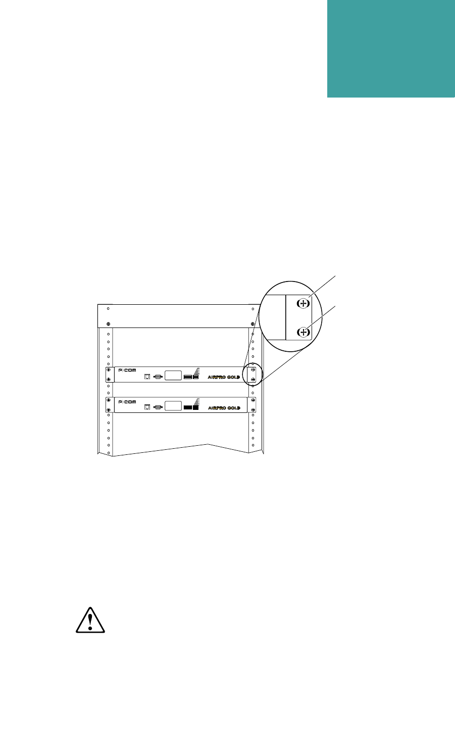
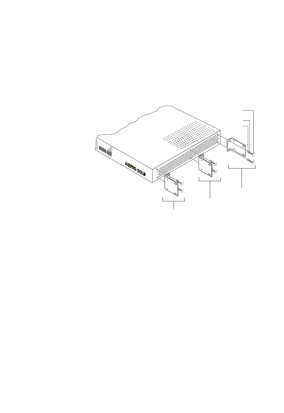
Figure 4-1 Rack Mounted Radios
An AirPro Gold® unit can be mounted in a standard 19 inch or 23 inch
equipment rack (see Figure 4-1), using brackets and hardware provided
in the shipping carton.
The rack mounting brackets can be installed on the unit chassis in one of
three positions: front, center, or rear, depending on how you want the
chassis positioned in the rack.
When installing the unit in a rack with other equipment, you must provide 1.75
inches of space above, below, and on each side of the unit to allow proper
ventilation.
For a 19 inch rack, short bracket flanges face the front of the unit. See
Figure 4-2 on page 4-2. For a 23 inch rack, longer bracket flanges face
the front of the unit. See Figure 4-3 on page 4-3.
Front Flange
Screws
(Supplied by
Customer)
APG2_003
Ethernet RS232 RSQ/RSSI
Alarm
Link
Frame TX
Ethernet Link
Ethernet Activity
Power
Ethernet RS232 RSQ/RSSI
Alarm
Link
Frame TX
Ethernet Link
Ethernet Activity
Power
RACK MOUNTING
19 inch Rack Mount
4-2 P-Com AirPro Gold
4
To mount the unit in a rack, you need:
•two rack-mount brackets (supplied)
•screws and washers to attach the brackets to the unit (supplied)
•1/4 inch hex nut driver or wrench
•screwdriver
. . . . . . . . . . . . . . . . . . . . . . . . . . . . . . . . . . . . . . . . . . . . . . . . . .
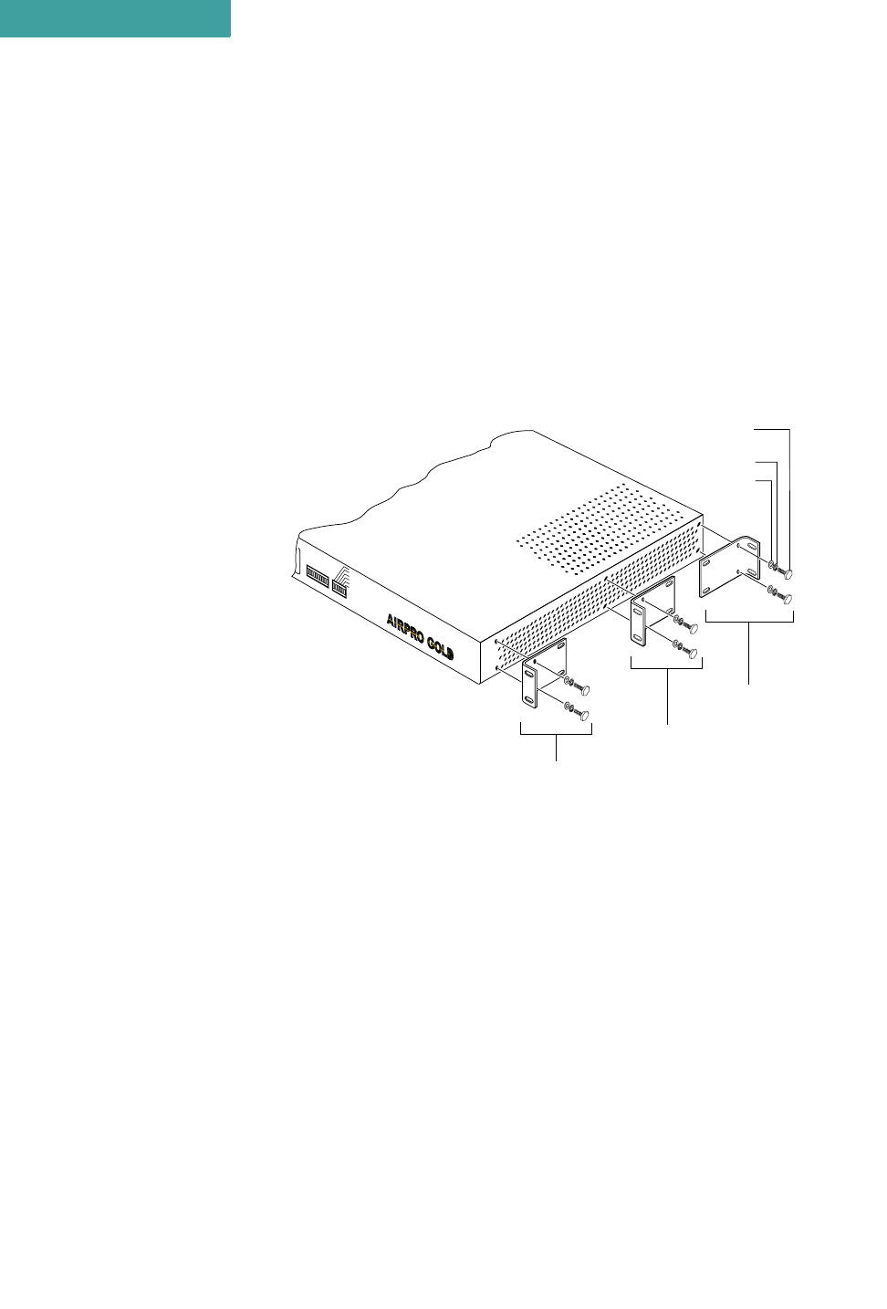
19 INCH RACK MOUNT
Refer to Figure 4-2 when mounting the unit in a 19 inch equipment rack.
Figure 4-2 Brackets for 19 inch Rack Mount
To mount the unit in a 19 inch rack:
1Choose the front, center, or rear rack mount position for the unit.
2Place a bracket on the chassis in the chosen position so that the bracket holes
line up with the threaded inserts on the side of the chassis, and the short flange
faces the front of the unit for the front or center position mount, or the back of
the unit for the rear position mount.
3Attach the bracket to the chassis.
•Use two of the screws, lock washers, and flat washers supplied with the unit.
4Repeat Step 2 and Step 3 to attach another bracket on the opposite side of the
chassis.
5Attach the bracketed chassis to the rack posts. Refer to Figure 4-1 on page 4-1.
•Align the front flanges of the brackets with the screw holes on the rack posts.
Front
Position
Center
Position
Rear
Position
Flat Washer
Lock Washer
Hex Head Screw
6-32 x 3/8 inch
APG2_004
RSQ/RSSI
Alarm
Link
Frame TX
Ethernet Link
Ethernet Activity
Power
. . . . .
RACK MOUNTING
23 inch Rack Mount
Hardware Installation Guide 4-3
•Hand-tighten the mounting screws to hold the unit and brackets in place on the
rack posts.
•Use a screwdriver to firmly attach the unit to the rack posts.
. . . . . . . . . . . . . . . . . . . . . . . . . . . . . . . . . . . . . . . . . . . . . . . . . .
23 INCH RACK MOUNT
Refer to Figure 4-3 when mounting the unit in a 23 inch equipment rack.
Figure 4-3 Brackets for 23 inch Rack Mount
To mount the unit in a 23 inch rack:
1Choose the front, center, or rear rack mount position for the unit.
2Place a bracket on the chassis in the chosen position so that the bracket holes
line up with the threaded inserts on the side of the chassis, and the short flange
faces the front of the unit for the front or center position mount, or the back of
the unit for the rear position mount.
3Attach the bracket to the chassis.
•Use two of the screws, lock washers, and flat washers supplied with the unit.
4Repeat Step 2 and Step 3 to attach another bracket on the opposite side of the
chassis.
5Attach the bracketed chassis to the rack posts. Refer to Figure 4-1 on page 4-1.
•Align the front flanges of the brackets with the screw holes on the rack posts.
•Hand-tighten the mounting screws to hold the unit and brackets in place on the
rack posts.
•Use a screwdriver to firmly attach the radio to the rack posts.
Front
Position
Center
Position
Rear
Position
Flat Washer
Lock Washer
Hex Head Screw
6-32 x 3/8 inch
APG2_005
RSQ/RSSI
Alarm
Link
Frame TX
Ethernet Link
Ethernet Activity
Power

RACK MOUNTING
23 inch Rack Mount
4-4 P-Com AirPro Gold
4

Hardware Installation Guide A-1
A
. . . . .
. . . . . . . . . . . . . . . . . . . . . . . . . . . . . . . . . . .
S
PECIFICATIONS
SPECIFICATIONS
General Specifications
A-2 P-Com AirPro Gold
A
. . . . . . . . . . . . . . . . . . . . . . . . . . . . . . . . . . . . . . . . . . . . . . . . . .
GENERAL SPECIFICATIONS
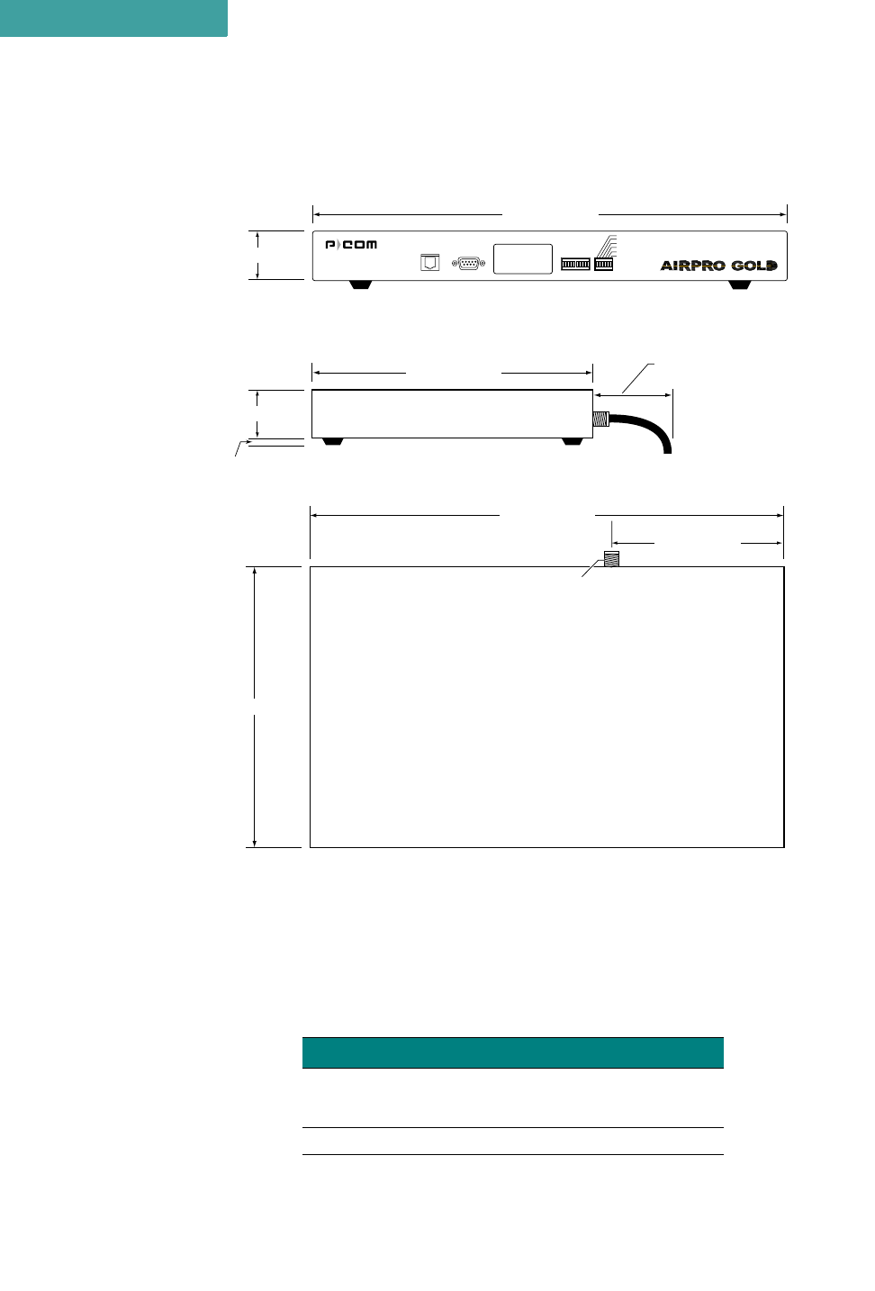
Figure A-1 Radio Dimensions
Table A-1 Mechanical Specifications
Parameter Specification
Dimensions Width: 17 inches (432 mm)
Height: 1.75 inches (44 mm)
Depth: 10 inches (254 mm)
Weight 10.3 pounds (4.7 kilograms)
front
1.75" (44 mm)
17" (432 mm)
5.75" (148 mm)
17" (432 mm)
1.75" (44 mm)
.5" (13 mm)
10" 254 mm)
10" (254 mm)
3" (76 mm)
minimum clearance
for pigtail antenna cable
Front View
Side View
Top View
Type "N"
Antenna Connector
APG2_006
Ethernet RS232 RSSI
Alarm
Link
Ethernet Link
Ethernet Activity
Data TX
Power

. . . . .
SPECIFICATIONS
General Specifications
Hardware Installation Guide A-3
Table A-2 Environment Specifications
Parameter Specification
Operating Temperature -5°C to 55°C (23°F to 131°F)
Storage Temperature –40°C to 80°C (–40°F to 176°F)
Operating Humidity 10% to 95% RH non-condensing
Storage Humidity
Elevation 200 feet (61 meters) below sea level to 13000 feet (3943
meters) above sea level
Mechanical Shock,
Vibration,Relative Humidity Verification standard ETSI 300-019-1-3 Class 3.1 (E)
Electromagnetic
Compatibility
Comply with FCC part 15.247
Comply with ETSI 300-328 v1.1.1 & 1.2.2
ETSI 300-826
SPECIFICATIONS
General Specifications
A-4 P-Com AirPro Gold
A
LED INDICATORS
Figure A-2 Front Panel Indicators
Table A-3 Front Panel Indicators
Name Color Function
RSSI Green
Steady illumination of LEDs indicates the strongest/highest quality of the receive signal.
Sequential illumination of all 10 LEDs indicates radio initialization self-test is in progress.
Blinking of all 10 LEDs in addition to audible alarm indicates Configuration Reset DIP switch is
ON and that the radio initial configuration and manufacturing image are selected for next reboot.
Blinking of the 1st of the 10 LEDs in addition to audible alarm indicates the wrong RF channel is
set on the DIP switches.
Blinking of the 3rd of the 10 LEDs in addition to audible alarm indicates that digital board
initialization has failed.
ALARM Red ON = Major event in the link (including remote units fail).
LINK Green ON = Link with far end unit/units is established.
ETHERNET
LINK Green ON = Connection with Ethernet segment is established
ETHERNET
ACTIVITY Yellow ON = Activity on Ethernet segment
DATA TX Yellow ON = Unit tranmits the Data frame (the Control frames are not)
POWER Yellow ON = power to the radio is on
APG2_007
net RS232 RSSI
Alarm
Link
Ethernet Link
Ethernet Activity
Data TX
Power
. . . . .
SPECIFICATIONS
General Specifications
Hardware Installation Guide A-5
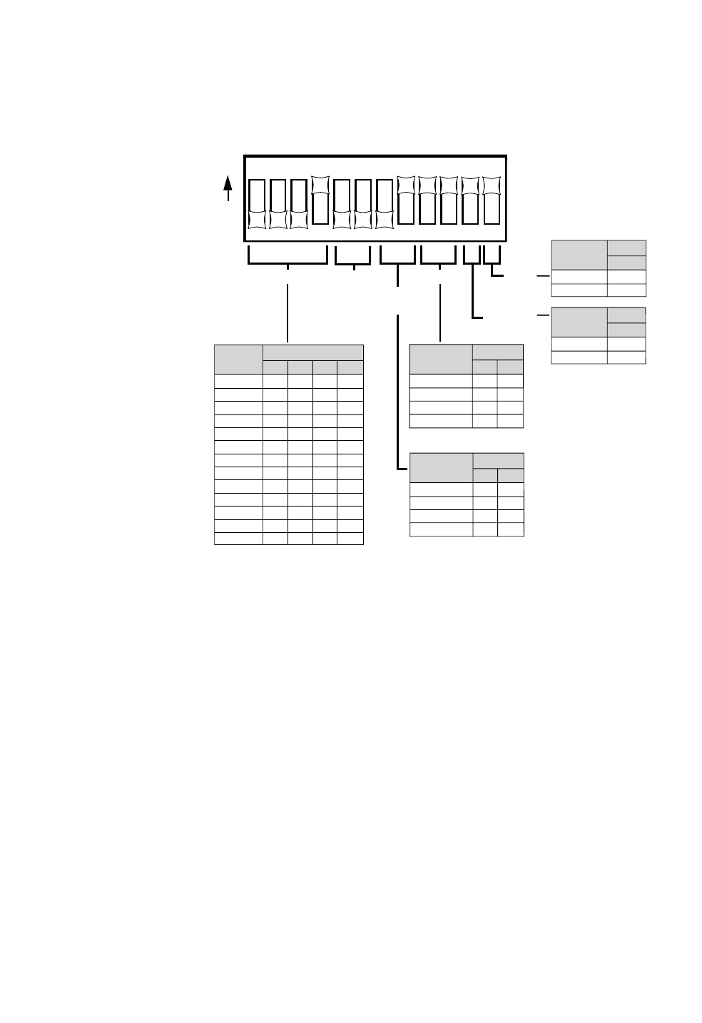
DIP SWITCHES
Figure A-3 DIP Switch Positions
All DIP switches must be in the OFF position when using the Command Line
Interface or Site Manager application to configure a radio.
The DIP switches become active only after system reboot, which can be done
by turning the main power switch off then on.
123456789101112
O
N
RF CHANNEL
Switch
1
OFF
OFF
OFF
OFF
OFF
OFF
OFF
ON
ON
ON
ON
ON
ON
OFF
OFF
OFF
ON
ON
ON
ON
OFF
OFF
OFF
OFF
ON
ON
OFF
ON
ON
OFF
OFF
ON
ON
OFF
OFF
ON
ON
OFF
OFF
ON
OFF
ON
OFF
ON
OFF
ON
OFF
ON
OFF
ON
OFF
ON
234
Channel
TOPOLOGY RESET
ANTENNA
ALIGNMENT
APG2_020
1
2
3
4
5
6
7
8
9
10
11
12
13
Star Remote
Star Base
Peer-to-Peer
Point-to-Point
Switch
9
OFF
OFF
ON
ON
OFF
ON
OFF
ON
10
Topology
Yes
No
Switch
12
ON
OFF
Reset
Alignment
Normal
Switch
11
ON
OFF
Antenna
Alignment
BPSK Mb/s
QPSK Mb/s
CCK 5.5 Mb/s
CCK 11Mb/s
Switch
7
ON
ON
OFF
OFF
ON
OFF
ON
OFF
8
Modulation
Mode
MODULATION
MODE
RESERVED
NOTE
✐
SPECIFICATIONS
General Specifications
A-6 P-Com AirPro Gold
A
EXTERNAL CONNECTORS
AC POWER CONNECTOR
Connector Location: Rear Panel
Connector Type: 3-pin Male
Figure A-4 AC Power Connector
ANTENNA CONNECTOR
Connector Location: Rear Panel
Connector Type: N-Type Female
Figure A-5 Antenna Connector
EXTERNAL USER INTERFACES
Table A-5 Network Ports
Table A-4 Power Specifications
Parameter Specification
AC Input Voltage 90 VAC to 240 VAC
AC Input Frequency 47 Hz to 63 Hz
AC Input Current 1A to 3.5A
Maximum Power Consumption 32.25 Watts, AC Power Supply
Port
Local or
Remote
through PC
over LAN
Remote
through PC
over Public
Telephone
Network
Local
through
Terminal
RS232 X X
Ethernet
(10/100 Base-T) X
APG2_015
GND
100–240 V~
0.5–0.2A
50/60 Hz
AC Power Connector
APG2_016
MADE IN USA MAC ADDRESS:
ANT
Antenna Connector

. . . . .
SPECIFICATIONS
General Specifications
Hardware Installation Guide A-7
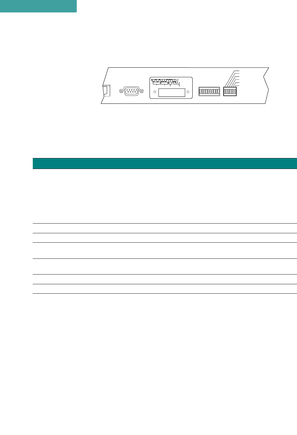
RS232 CONNECTOR
Connector Location: Front Panel
Connector Type: RS-232, DB 9-pin Male
Figure A-6 RS-232 Connector
Table A-6 RS-232 Port Pin Assignments
Pin Circuit Description Function
1 100 Received line signal detect from terminal
2 104 Received data from terminal
3 103 Transmitted data from radio
4 108/2 Data terminal ready from radio
5 102 Signal common circuit ground
6 107 Device ready from terminal
7 105 Request to send from radio
8 106 Clear to send from radio
9 not used
Pin 1 Pin 5
Pin 6 Pin 9
APG2_023
SPECIFICATIONS
General Specifications
A-8 P-Com AirPro Gold
A
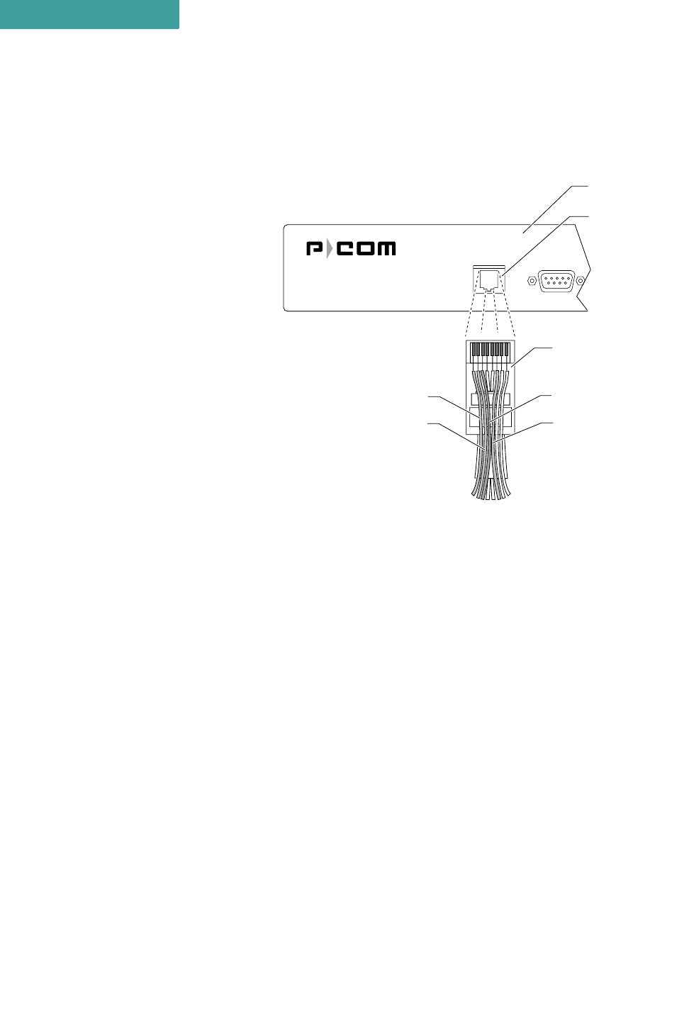
ETHERNET CONNECTOR
Connector Location: Front Panel
Connector Type: RJ-45 Jack
Figure A-7 Ethernet Jack
Any pin not shown in Figure A-7 is not connected, i.e., pin 4, pin 5,
pin 7, pin 8.
Ethernet RS232
APG2_017
12345678
Pin 1
TX+
Pin 2
TX–
Pin 3
RX+
Rear Panel
RJ-45
10BaseT
Connector
RJ–45 Plug
(Hook Underneath)
Pin 6
RX–
NOTE
✐

. . . . .
SPECIFICATIONS
Radio Specifications
Hardware Installation Guide A-9
. . . . . . . . . . . . . . . . . . . . . . . . . . . . . . . . . . . . . . . . . . . . . . . . . .
RADIO SPECIFICATIONS
Table A-7 Radio Specifications
Parameter Specification
Frequency Range 2400 GHz to 2483.5 GHz (S-Band)
Radio Technology Spread Spectrum using Direct Sequence
PN Sequence Length 32 bits
Modulation Technique BPSK (R=1Mb/s), QPSK (R=2Mb/s), CCK (R=5.5Mb/s,
R=11Mb/s)
Channel Bandwidth 20.0 MHz
Sync Word Length 16 bits
Processing Gain >10 dB
Radio Protocol TDD
Frequency Stability ±5 ppm initial stability over temp with ± 2ppm aging/year, ±10
ppm/10years
System Gain
116 dB (for R=1Mb/s, BPSK mode)
113 dB (for R=2Mb/s, QPSK mode)
111 dB (for R=5.5Mb/s, CCK mode)
108 dB (for R=11Mb/s,CCK mode)
Number of non-overlapping
channels 4
Table A-8 Transmitter Specifications
Parameter Specification
Load Impedance 50 ohms
Power Output 26 dBm Maximum with 38 dB of Dynamic range
Accuracy ±2 dB overall RF channel
±2 dB @ 0 dBm
±2 dB from 0°C to 50°C (32°F to 122°F)
Output Level Control 30 settings, 1 dBm increments
RF Port Protection None

SPECIFICATIONS
Center Frequencies
A-10 P-Com AirPro Gold
A
. . . . . . . . . . . . . . . . . . . . . . . . . . . . . . . . . . . . . . . . . . . . . . . . . .
CENTER FREQUENCIES
Table A-9 Receiver Specifications
Parameter Specification
Sensitivity*
(@ 10E-6 BER)
* typical room temperature
–94 dBm (R =1 Mb/s, BPSK mode)
–91 dBm (R =2 Mb/s, QPSK mode)
–88 dBm (R =5.5 Mb/s, CCK mode)
–85 dBm (R =11 Mb/s, CCK mode)
Noise Figure 5 dB
Input Impedance 50 ohms
RF Input Protection None
Maximum RF Input Power –10 dBm
Dynamic Range 70 dB
Table A-10 RF Channel Center Frequencies
Center
Frequency
(MHz) RF Channel
2411.000 1
2416.000 2
2421.000 3
2426.000 4
2431.000 5
2436.000 6
2441.000 7
2446.000 8
2451.000 9
2456.000 10
2461.000 11
2466.000 12
2471.000 13

Hardware Installation Guide Index-1
. . . . .
. . . . . . . . . . . . . . . . . . . . . . . . . . . . . . . . . . .
I
NDEX
Numerics
19 inch rack mount 4-1, 4-2
23 inch rack mount 4-1, 4-3
A
antenna connection 3-2
antenna connector 1-5, A-6
C
center frequencies A-10
Command Line Interface 1-3, 3-7
configuration
basic 3-5
D
DIP switches 1-3, 1-4, 3-5, 3-7, A-5
E
Ethernet connector 1-4
F
front panel 1-4
front panel indicators A-4
G
ground connection 3-1
grounding stud 1-5
L
LAN connection 3-2
N
network topologies 1-3, 2-1, 3-5,
3-6, 3-8
centralized 1-3, 2-3
peer-to-peer 1-3, 2-2
point-to-point 1-3, 2-2
range 2-4
star 1-3, 2-3
notes, cautions, and warnings xvii
O
organization of Installation
Guide xvi
P
packet-based networks 2-1
pin assignments
RS-232 port A-7
power connection 3-3
power connector 1-5, A-6
power indicator 1-4
power switch 1-5
product features 1-5
R
rack mount 4-1
radio dimensions A-2
rear panel 1-5
reboot 3-5
RF channel 3-5, 3-6, 3-8, A-10
RJ-45 connector 3-2, A-8
RS-232 connector A-7
RS-232 port 1-4
RSQ 1-4
S
Site Manager application 1-3, 3-9
specifications
environment A-3
general A-2
mechanical A-2
radio A-9
radio weight A-2
receiver A-10
transmitter A-9
T
telephone modem 3-4
terminal configuration 3-7
terminal emulation program 3-7
terminal port 1-4