Wave Wireless SL9200 2.4, 5.8 & 4.9GHz (PSB) Wireless Router User Manual 34357 MNL Rev B
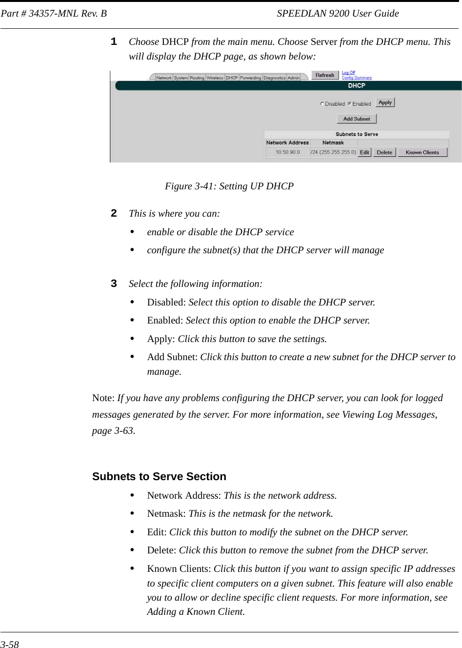
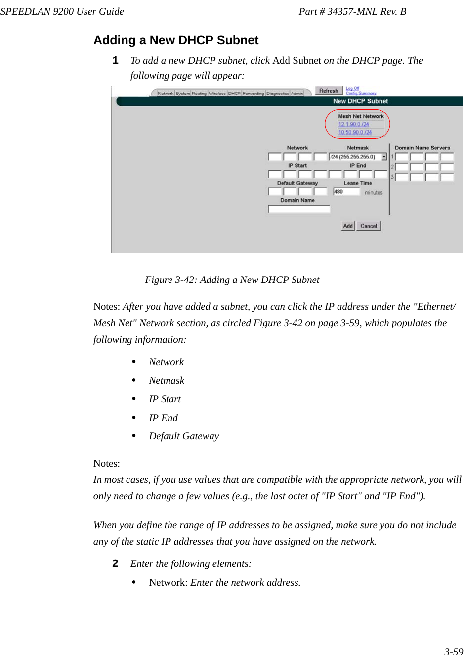
Wave Wireless Corporation 2.4, 5.8 & 4.9GHz (PSB) Wireless Router 34357 MNL Rev B
UserManual.wiki
>
Wave Wireless
>
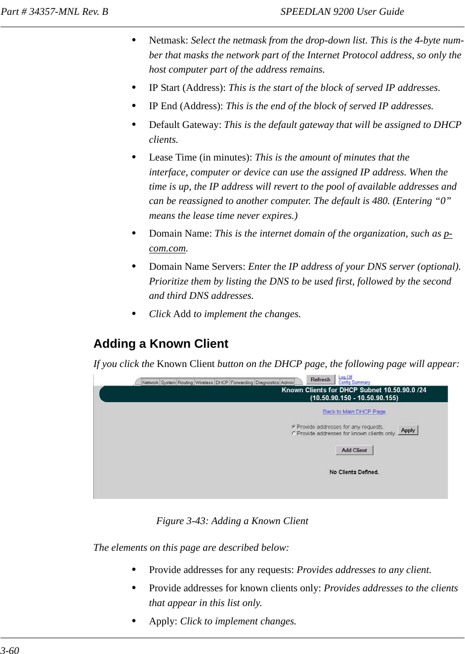
SL9200 User Manual
>
Users Manual 1
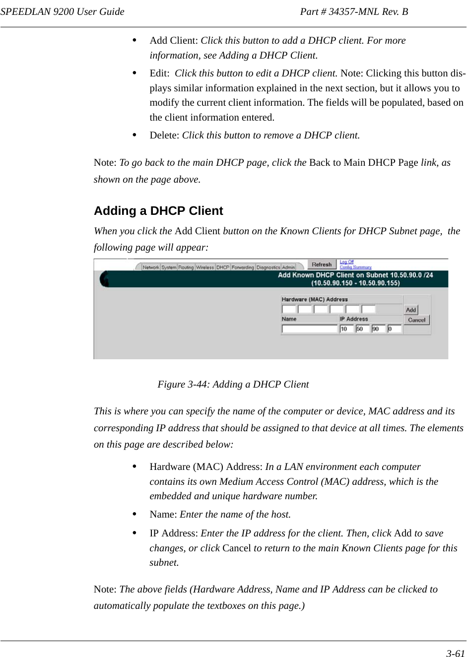
Contents
1.
Users Manual 1
2.
Users Manual 2
3.
User Guide Addendum
4.
Users Manual Part 1
5.
Users Manual Part 2
Users Manual 1
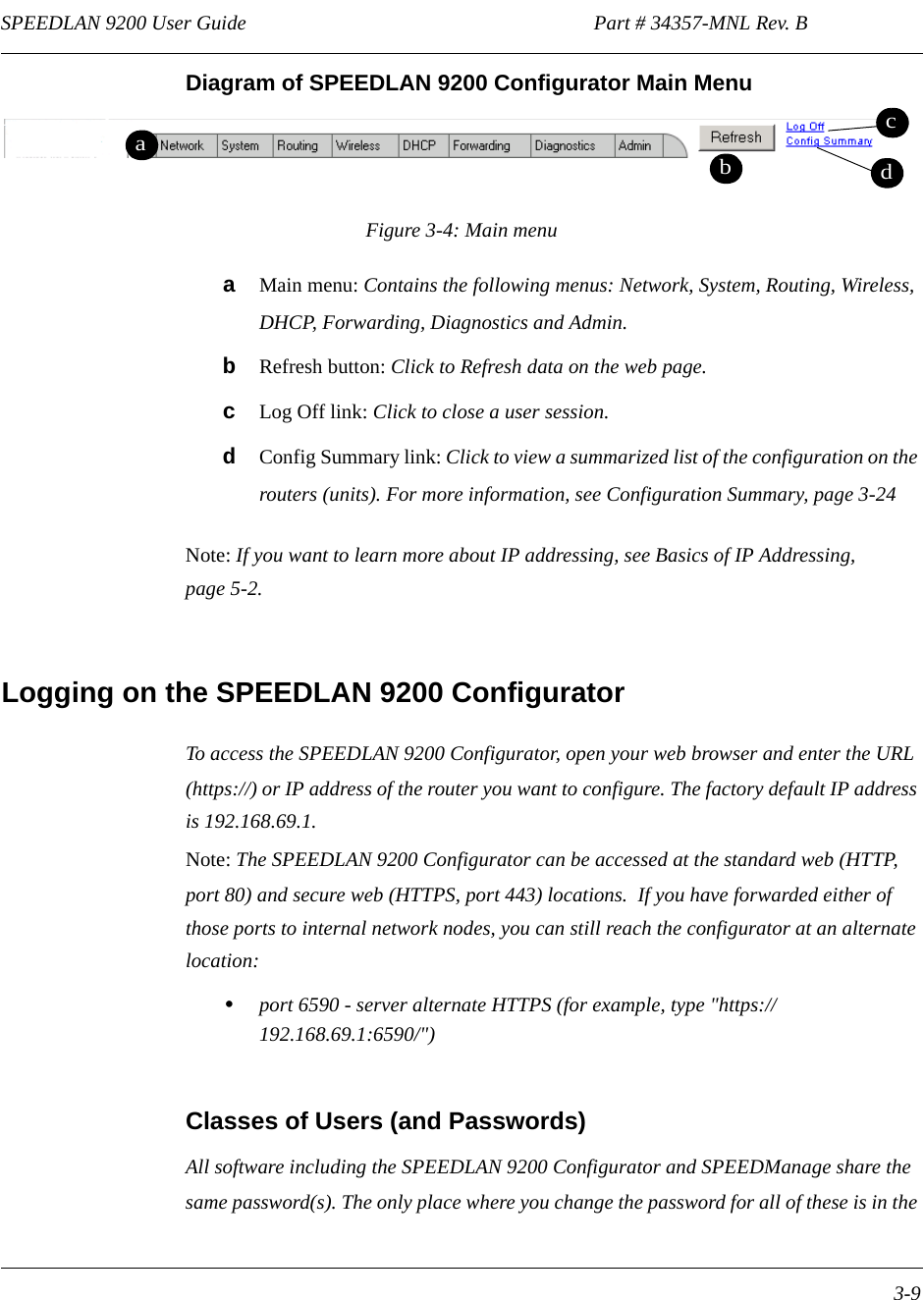
Navigation menu
Upload a User Manual
Namespaces
Wiki Guide
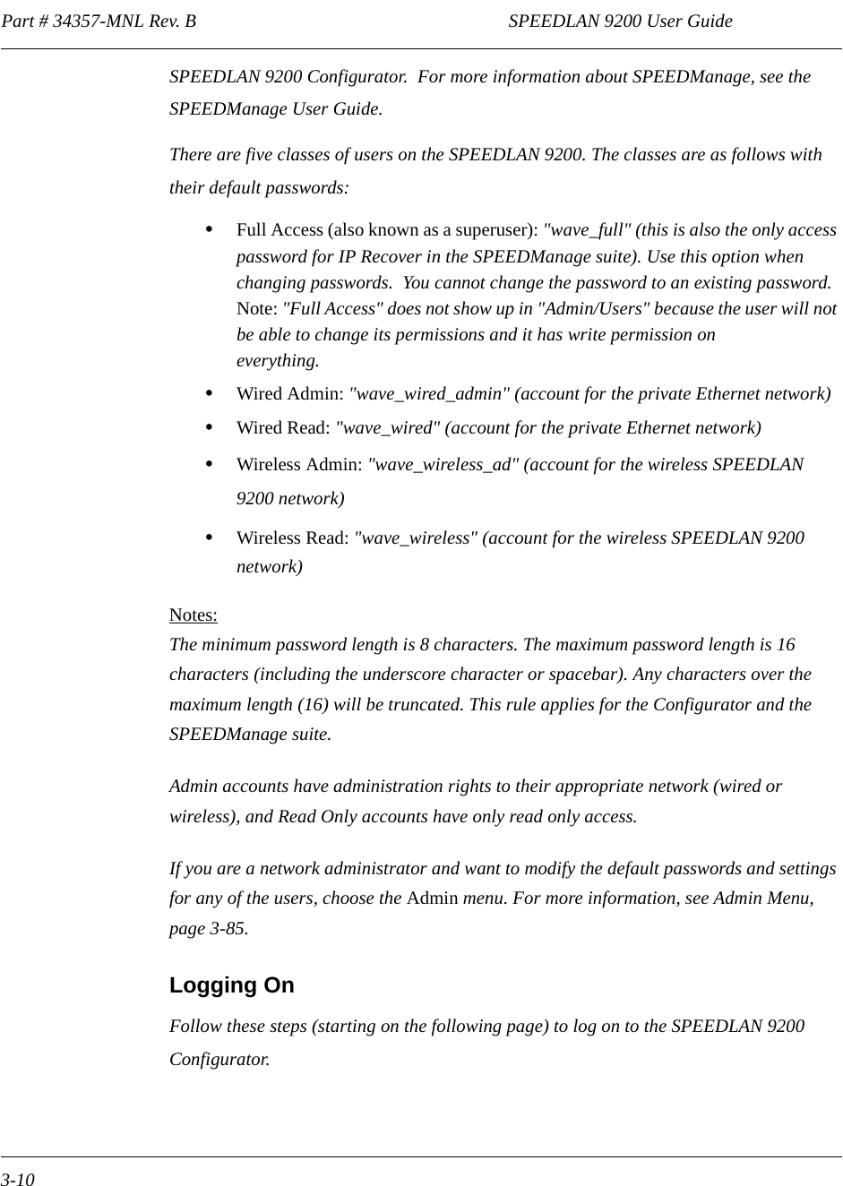
HTML
PDF
Info
Views
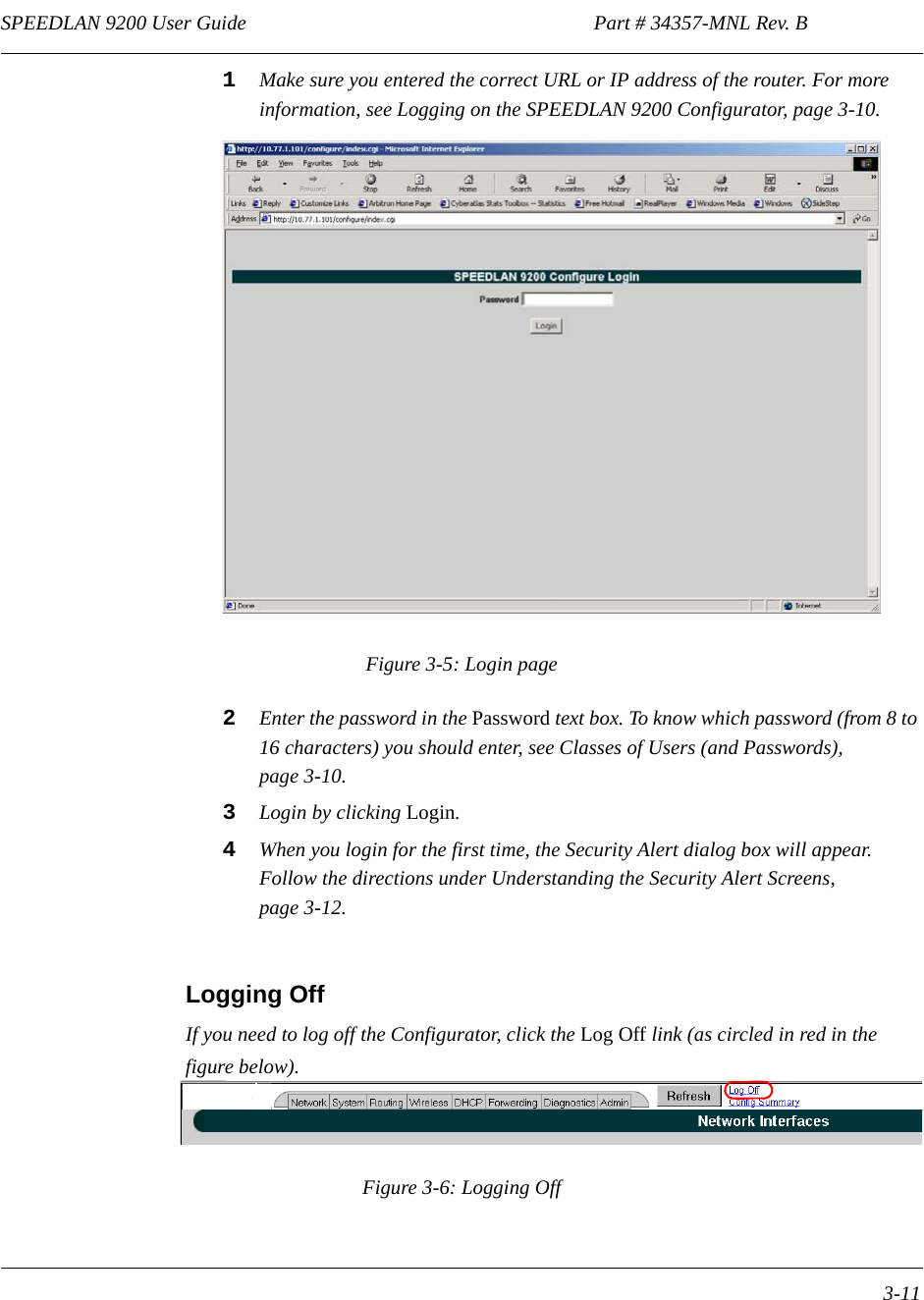
User Manual
Discussion / Help
Navigation


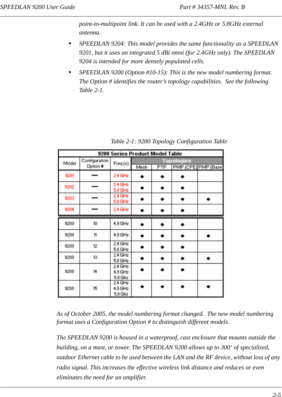
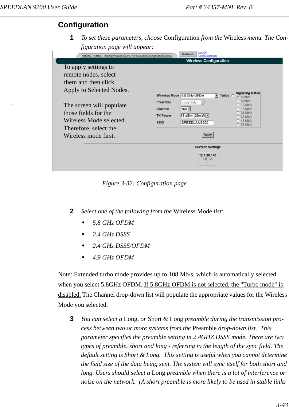
![SPEEDLAN 9200 User Guide Part # 34357-MNL Rev. B 1-5 •Hardware AES 128-bit encryption for security between SPEEDLAN 9200 routers.•You can recover lost IP addresses. (Use IP Recover in SPEEDManage.)•Bandwidth Limiting: Users will now have the ability to control the bandwidth use of each SpeedLAN unit in a mesh or a star network. This feature allows control-ling the amount of traffic from the Wireless Port to the Ethernet Port and also from the Ethernet Port to the Wireless Port with independent parameters. •ToS [Type of Service]: ToS provides a comprehensive traffic classification scheme and the choice of 8 levels of priority selection for each classification. Tagged traffic is classified by its DiffServ Code Point, and untagged traffic by other set of properties like for example the protocol and IP port.•License Control: Allows a Speed LAN unit to be licensed to communicate with a certain number of mobile clients that associate to it. The license if provided by uploading to a given unit a license file specific for that unit. This is a feature once believed by marketing to be a potential source of revenue. [A mobile client is a laptop or PDA with a standard radio card that and on which our mobile client application has been installed]•Configuration File Upload/Download: This feature was added at the request of several customers since it helps the operations, administration and maintenance of a network because it simplifies the process of unit configuration that generally requires a good degree of expertise and can lead to errors. •System Log: A configurable Sys Log capability was added to improve trouble-shooting and general network management.•Ethernet Port DHCP Client: The DHCP client has been enhanced. The new design propagates and uses additional fields provided by the DHCP server in the network.•Wireless Port DCHP Server: Server support has been added to the Wireless Port to assign IP addresses to mobile mesh clients.Note: Advanced Encryption Standard was adopted by the National Institute of Standards and Technology in October of 2000. AES presents a new level in computer networking security, especially important in wireless communications because wireless circuits are easier to tap than their hard-wired counterparts. AES is more difficult to crack than its predecessor Data Encryption Standard. These routers use an AES 128-bit encryption key.Encryption Note! A Web browser must support 128 bit encryption in order to be used with the Configurator. For more information about AES, visit http://www.nist.gov. This User](https://usermanual.wiki/Wave-Wireless/SL9200.Users-Manual-1/User-Guide-603688-Page-14.png)
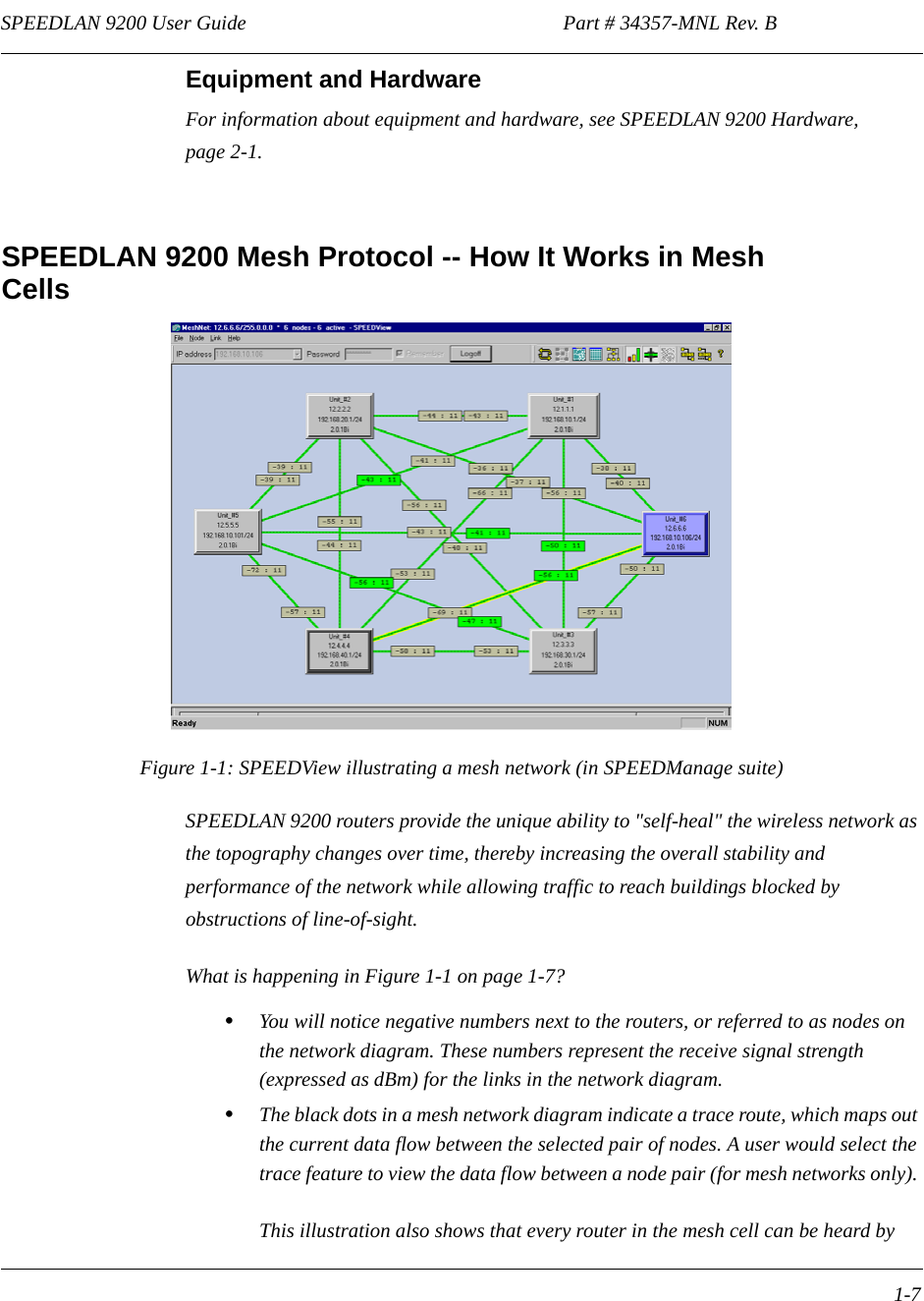
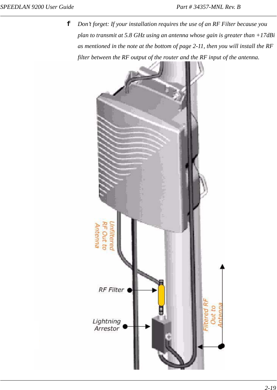
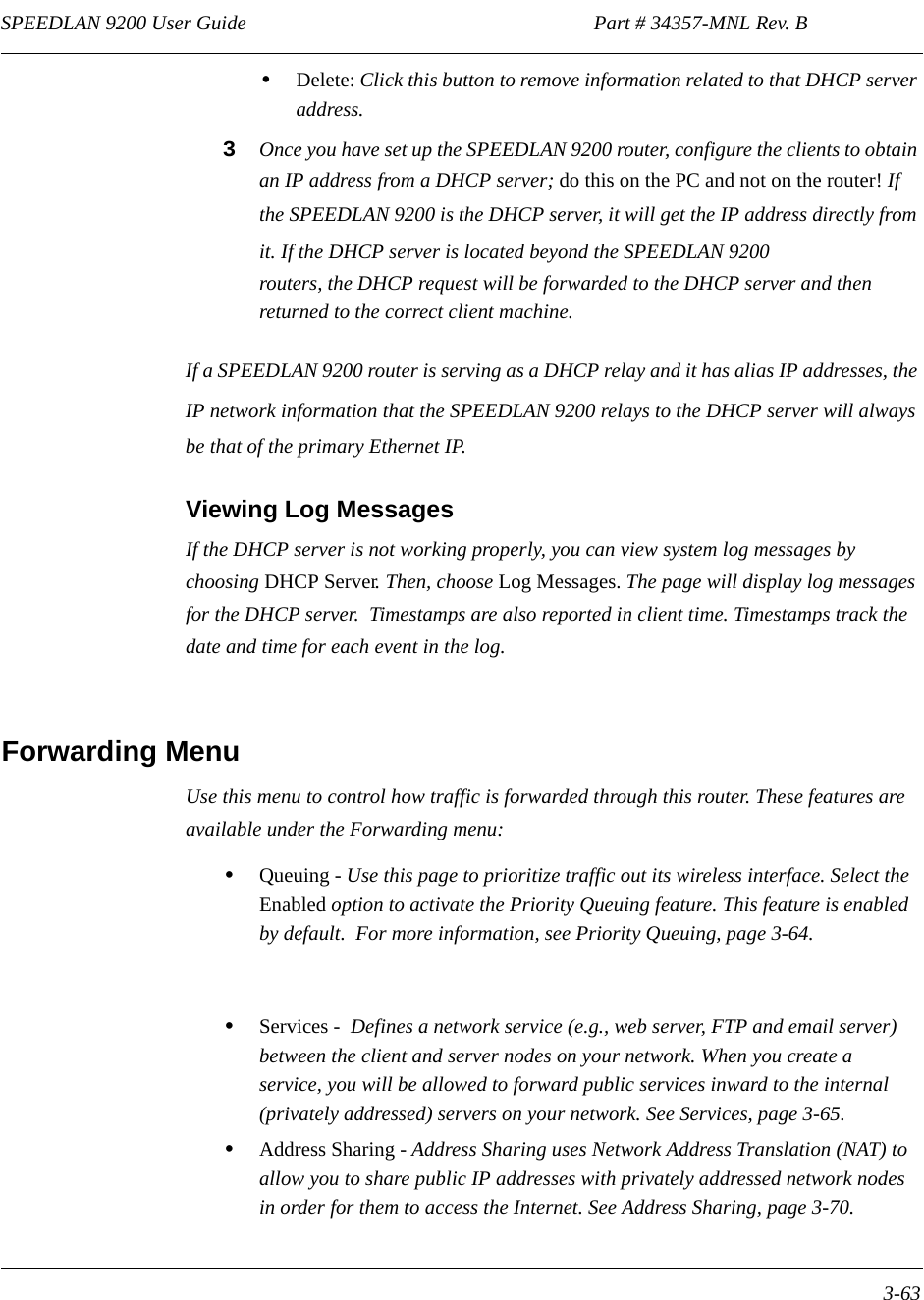
![Part # 34357-MNL Rev. B SPEEDLAN 9200 User Guide 1-8every other router in the cell, except for the blocked link indicating that there is no signal between those two nodes. SPEEDView allows you to block traffic over any link in the cell. When you block a connection, the node pair will not be able to communicate. The advantage of blocking a connection is verifying that the path can be re-routed for successful connectivity. (This is done using the "Block" feature in SPEEDView. The broken [or disconnected] link will appear as a red line. This link also appears when there is no signal between two nodes.) •SPEEDView can also be used to perform bandwidth, link and ping tests. Routing Around ObstaclesFigure 1-2: Routing around obstaclesExplaining this scenario on the simplest level (using the Mesh protocol as shown in Figure 1-2 on page 1-8). A can route a packet to B, despite the tree obstruction (block of trees) within the path. How does this procedure work? 1A has line-of-sight to C but not to B.2C has line-of-sight to A and to B.The most efficient path in this case is to hop from A to C to B. Note: No manual programming is required because A automatically detects its neighboring router (in this case C, and B and detect a clear path to C). Therefore, the packet is successfully routed around the obstacle between B and A. This process creates a more scalable, flexible, and extended wireless network (as shown in Document Changes & Corrections/Firmware Updates, page 1-11). Obstacle A E B C D](https://usermanual.wiki/Wave-Wireless/SL9200.Users-Manual-1/User-Guide-603688-Page-17.png)


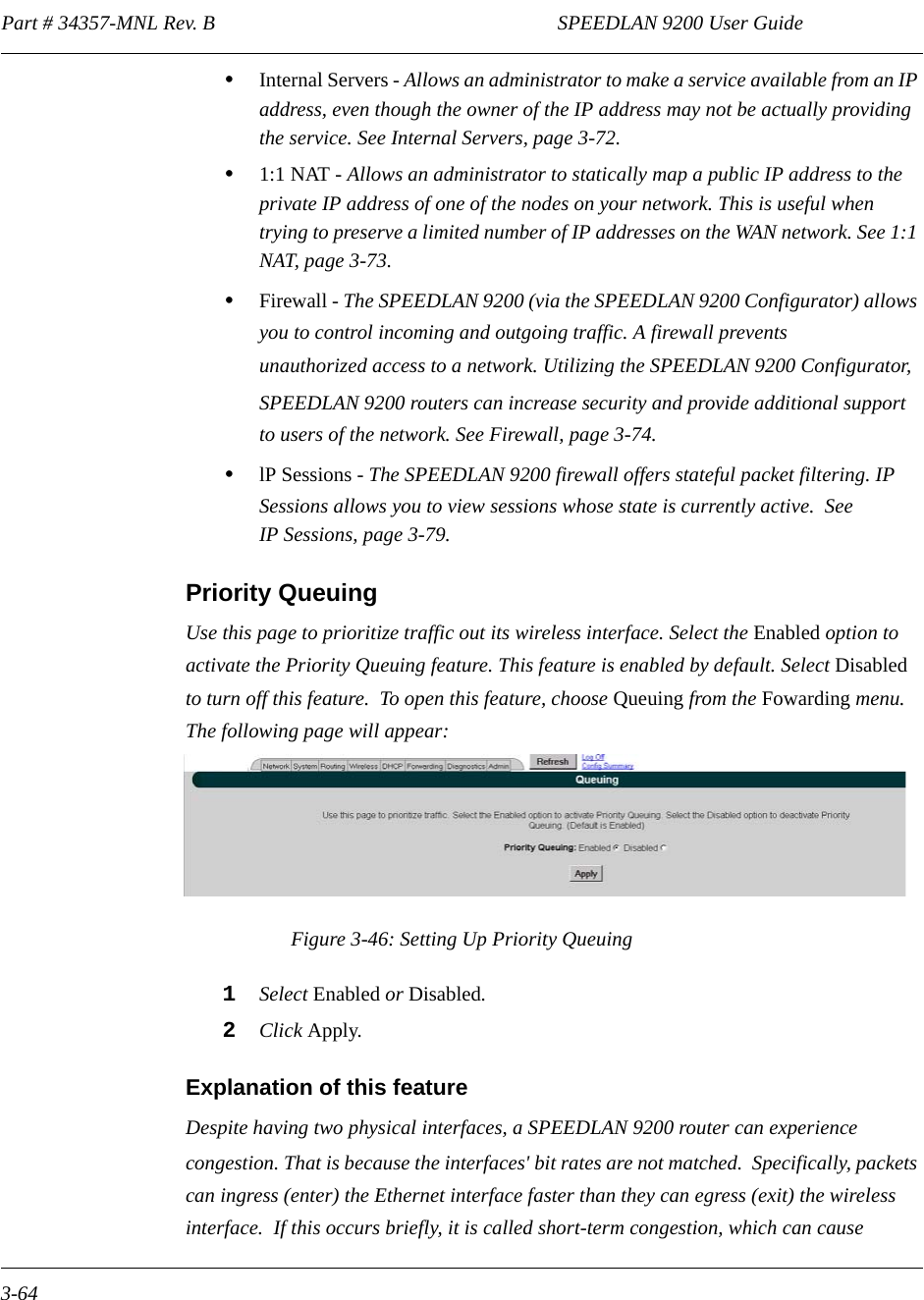
![Part # 34357-MNL Rev. B SPEEDLAN 9200 User Guide 3-32VIEW LOGSTo access View System Logs page, choose Message Log->View Logs from System main menu.Figure 3-24: View LogfileThe following controls are available:•Specify number of last recorded messages to be displayed;•Filter messages by specifying the text (case insensitive);•Choose source of message recorder: kernel, wlan, dhcp, snmp, config manager Jan 29 09:06:51 hostname kernel: wlan[ath0]: Set ath0 operation mode: HOSTAP Jan 29 09:06:51 hostname kernel: wlan[ath0]: Set ESSID: "SPEEDLAN9200" Jan 29 09:06:51 hostname kernel: wlan[ath0]: Set Turbo: Disabled Jan 29 09:06:51 hostname kernel: wlan[ath0]: Set Tx power: 17 dBm Jan 29 09:06:51 hostname kernel: wlan[ath0]: Set Preamble: Long Only Jan 29 09:06:51 hostname kernel: wlan[ath0]: Set ACL Policy: OPEN Jan 29 09:07:03 hostname sshd[319]: Server listening on 0.0.0.0 port 22 Jan 29 09:07:09 hostname rc.local: Starting 'socksvr' ... Jan 29 09:07:10 hostname rc.local: Starting 'sendfilemc' ... Jan 29 09:07:10 hostname rc.local: Starting 'ip_recov' ... Jan 29 09:07:10 hostname rc.local: Starting 'k2status' ...Log OffConfig Summary](https://usermanual.wiki/Wave-Wireless/SL9200.Users-Manual-1/User-Guide-603688-Page-75.png)
![SPEEDLAN 9200 User Guide Part # 34357-MNL Rev. B 3-33 PREDEFINED LOG MESSAGESKernel LogsNatSemi DP8381[56] at 0xc4808000, 00:05:d5:12:67:46, IRQ 11. 00:05:d5:12:67:46, IRQ 11.Setting full-duplex based on negotiated link capability.Atheros 5212: mem=0xa0000000, irq=10Atheros Driver LogsINFO level logswlan: 0.8.4.4 (EXPERIMENTAL)ath_hal: 0.9.12.14 (AR5210, AR5211, AR5212)ath_pci: 0.9.4.11acl: ACL module 1.0 - loadedAtheros driver version 0.8.4.4 loadedAtheros driver unloadedmac acl policy registeredSet atheros device operation mode: {ADHOC,HOSTAP, … }Set ESSID: {string upto 32 character} Set Wireless Mode: {IEEE 802.11a, IEEE 802.11b and IEEE 802.11g}Set Turbo: {Disabled/Enabled}Set Tx power: {power in dBm}Set Preamble: { Short & Long ; Long Only }Set ACL Policy: {OPEN,ALLOW,DENY}Set signaling rate: {rate in hexadecimal}Set Rate: Set RTS/CTS: {Enabled/Disabled} Threshold: {1 up to 2311}Set Desired Base/Primary MAC: {MAC address}Set Channel: { channel value }Set SW/retry: {Disabled/<value>}Set encryption stuffSet Key ID: {1-4}; MAC: {MAC address}Deleted unicast key for MAC: {MAC address}Deleted shared key ID: {1-4}Added ACL MAC: {MAC address}Deleted ACL MAC: {MAC address}Error Level LogsUnable to attach hardware; HAL status {<status>}Failed to allocate descriptors: {<error code>}](https://usermanual.wiki/Wave-Wireless/SL9200.Users-Manual-1/User-Guide-603688-Page-76.png)
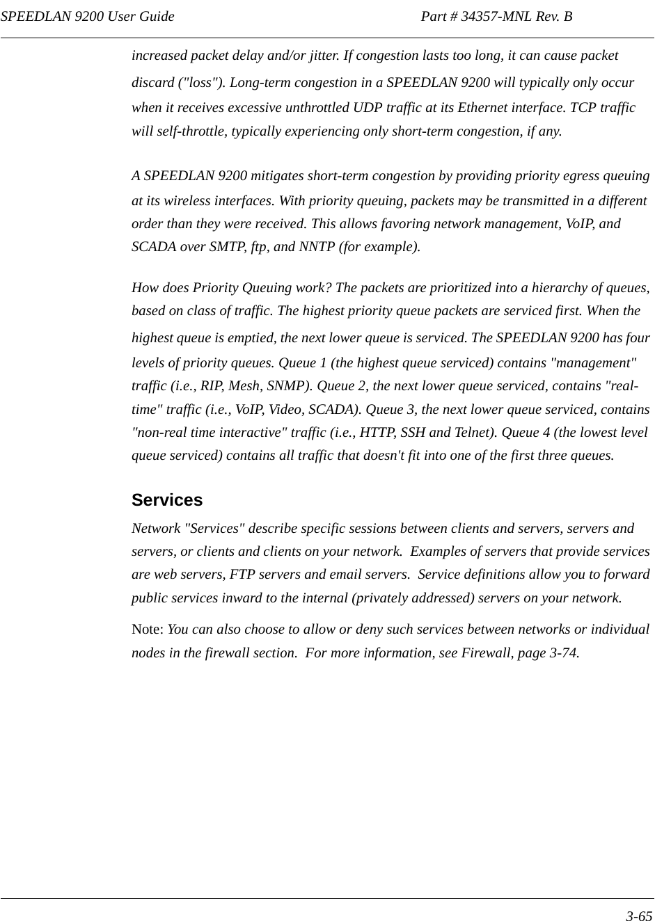
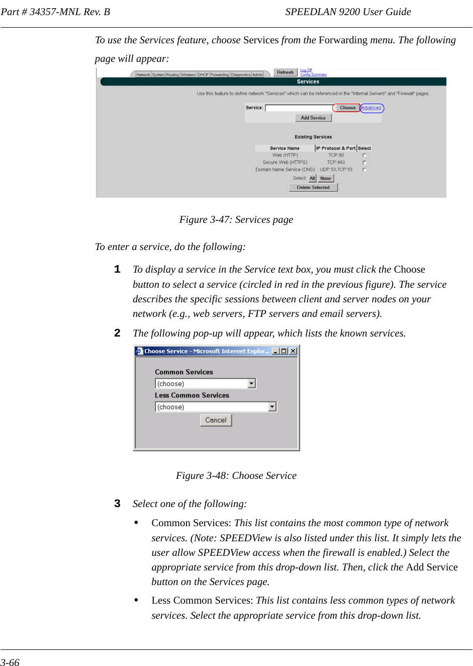
![SPEEDLAN 9200 User Guide Part # 34357-MNL Rev. B 3-67 Your selection will be added to the Services page. Then, click the Add Ser-vice button on the Services page. Creating an Advanced ServiceIf you cannot locate the service you want to add, you can define an advanced service by clicking the Advanced link to the right of the "Choose" button (as circled in blue in Figure 3-47 on page 3-66). The following pop-up will appear:Figure 3-49: Advanced Services (adding AIM)Advanced services can have one or more IP protocols. Under Advanced Services, you will need to know the name of the service (or it can be unique), the protocol(s) used and the ports needed to operate the service. For the TCP and UDP protocols, you can define specific ports, or a range of ports. Enter the following information:1Service Name: Enter a new name for the service. (In the previous figure, the user entered "AIM" because the user wanted to add AOL Instant Messenger.)2IP Protocol: Select an IP protocol for your service. If you select any protocol other than TCP or UDP, the protocol will be immediately added to the list of pro-tocols for this service. (In previous figure, the user selected "UDP" because it is the protocol for AIM.)3[Port range]: If you select TCP or UDP, you can specify a port or a port range. Then, click Add Protocol to add that protocol and port to the list. Click Clear to remove the IP protocol list if you need to start over. (In the previous figure, the user entered port "5190".) If you are only entering a single port, enter it in the left Port Range text box.4IP Protocols and Ports: After clicking Add Protocol, this text box will bepopulated with the data, based on what you entered in the IP Protocol, Port num-ber and Port range text boxes.](https://usermanual.wiki/Wave-Wireless/SL9200.Users-Manual-1/User-Guide-603688-Page-110.png)