Wave Wireless SL9200 2.4, 5.8 & 4.9GHz (PSB) Wireless Router User Manual 34357 MNL Rev B
Wave Wireless Corporation 2.4, 5.8 & 4.9GHz (PSB) Wireless Router 34357 MNL Rev B
Contents
Users Manual 1

Wave Wireless
Wave Wireless Copyright Statement (c) 2005.
Wave Wireless Corp. provides this Installation Guide without warranty of any kind, either express or implied, including, but
not limited to, the implied warranties of merchantability and fitness for a particular purpose. Wave Wireless Corp. may make
improvements and changes to the product described in this manual at any time and without any notice. Wave Wireless Corp.
assumes no responsibility for its use, nor any infringements of patents or other rights of third parties that would result.
This publication may contain technical inaccuracies or typographical errors. Periodic changes are made to the information
contained herein. These changes, and mechanical corrections, will be incorporated in subsequent revision levels of the publi-
cation.
No part of this publication may be stored in a retrieval system, transmitted, or reproduced in any way, including but not limited
to photocopy, photograph, magnetic or other records, without the prior written permission of Wave Wireless Corp.
All other brand and product names are the trademarks of their respective holders.
Wave Wireless
1996 Lundy Ave.
San Jose, CA 95131
www.wavewireless.com
Technical Support
408-943-4202 (phone)
408-943-4355 (fax)


SPEEDLAN 9200 User Guide Part # 34357-MNL Rev. B
Contents-1
CHAPTER 1 - Introduction
Features and Benefits ....................................................................................................................................1-2
SPEEDLAN 9200 Features ..................................................................................................................1-2
ISP Functionality ..................................................................................................................................1-3
IP Router Functionality ........................................................................................................................1-3
Configuration Management..................................................................................................................1-4
SPEEDManage .....................................................................................................................................1-4
Features (and Benefits).........................................................................................................................1-4
Priority Queuing ...................................................................................................................................1-5
SNMP ...................................................................................................................................................1-6
Equipment and Hardware .....................................................................................................................1-7
SPEEDLAN 9200 Mesh Protocol -- How It Works in Mesh Cells ..............................................................1-7
SPEEDLAN’s Mesh Cell Architecture ................................................................................................1-9
SPEEDLAN 9200 Mesh Core Components.........................................................................................1-9
Neighbor Discovery.....................................................................................................................1-9
Topology Updates........................................................................................................................1-9
Routing.......................................................................................................................................1-10
Why SPEEDLAN Outperforms Other Routing Equipment ......................................................1-10
Document Changes & Corrections/Firmware Updates...............................................................................1-11
Contacting Technical Support.....................................................................................................................1-11
CHAPTER 2 - Hardware
Rooftop and Tower Installations Warning....................................................................................................2-2
Regulatory Information.................................................................................................................................2-2
Declaration of Conformity for RF Exposure.................................................................................................2-3
General Safety Requirements for Installation of SPEEDLAN 9200 Models ...............................................2-3
Hardware Overview ......................................................................................................................................2-4
Tips for Antenna Alignment ........................................................................................................2-5
Drawings of Outdoor, Remote-Mounted Components .................................................................................2-6
Indoor Junction Box .............................................................................................................................2-6
The SPEEDLAN 9201/9204 with an Integrated Omni-Directional.....................................................2-7
Bottom View of SPEEDLAN 9201/SPEEDLAN 9204 ......................................................................2-8
System Description...............................................................................................................................2-8
Package Contents.................................................................................................................................2-8
Installation Steps for the SPEEDLAN 9201/SPEEDLAN 9204 ..........................................................2-9
Installation Diagram of the SPEEDLAN 9201/SPEEDLAN 9204....................................................2-11
The SPEEDLAN 9202/SPEEDLAN 9203 with External Antenna ............................................................2-12
Bottom View of SPEEDLAN 9202/SPEEDLAN 9203 .....................................................................2-13
System Description.............................................................................................................................2-13
Package Contents................................................................................................................................2-13
Installation Steps for the SPEEDLAN 9202/SPEEDLAN 9203 ........................................................2-14
SPEEDLAN 9202/SPEEDLAN 9203 Installation Diagram ............................................................2-21

Part # 34357-MNL Rev. B SPEEDLAN 9200 User Guide
Contents-2
CHAPTER 3 - General Functions of the Configurator
Manual Initial Configuration of the SPEEDLAN 9200................................................................................3-2
Prerequisites..........................................................................................................................................3-2
Connecting a SPEEDLAN 9200 and a Client PC ................................................................................3-3
Configuring the SPEEDLAN 9200 ......................................................................................................3-5
Wireless Interface IP Address Assignment ..........................................................................................3-5
Automating the Configuration of Multiple SPEEDLAN 9200s...........................................................3-6
Completing Configuration....................................................................................................................3-6
Adding Additional SPEEDLAN 9200s to the Wired Network ............................................................3-6
Overview of the SPEEDLAN 9200 Configurator General Main Menu .......................................................3-6
How the Configurator Menu is Structured...................................................................................3-6
Network menu..............................................................................................................................3-7
System menu................................................................................................................................3-7
Routing menu...............................................................................................................................3-7
Wireless menu..............................................................................................................................3-8
Diagram of SPEEDLAN 9200 Configurator Main Menu ...........................................................3-9
Logging on the SPEEDLAN 9200 Configurator ........................................................................................3-10
Classes of Users (and Passwords) ......................................................................................................3-10
Logging On.........................................................................................................................................3-11
Logging Off ........................................................................................................................................3-12
Understanding the Security Alert Screens..........................................................................................3-12
After Logging On ...............................................................................................................................3-15
Helpful Information to Know......................................................................................................................3-16
How do you select the router? ............................................................................................................3-16
References on Setting Up the Router .................................................................................................3-16
Caching - viewing the most recent version of a page.........................................................................3-17
Session Activity..................................................................................................................................3-17
SPEEDLAN 9200 Firmware Updates, SPEEDManage or Other Utility Programs...........................3-17
If You Need a Temporary IP Address................................................................................................3-18
The Configuration Menu.............................................................................................................................3-18
Network Menu.............................................................................................................................................3-18
Network Interfaces .............................................................................................................................3-18
IP Address Configuration ...................................................................................................................3-18
CIDR Table (For Netmask Information Purposes)....................................................................3-20
Alias IP.......................................................................................................................................3-21
Virtual Addresses ...............................................................................................................................3-22
System Menu...............................................................................................................................................3-24
Configuration Summary .....................................................................................................................3-24
SNMP .................................................................................................................................................3-25
Version................................................................................................................................................3-28
Host Name ..........................................................................................................................................3-28
Password.............................................................................................................................................3-29
Reboot.................................................................................................................................................3-29
Routing Menu..............................................................................................................................................3-36
Def Gateway.......................................................................................................................................3-37
RIP2 Setup..........................................................................................................................................3-37
RIP Settings ........................................................................................................................................3-38

SPEEDLAN 9200 User Guide Part # 34357-MNL Rev. B
Contents-3
Authentication on RIP-2 MD5...................................................................................................3-39
Route Table.........................................................................................................................................3-41
Static Route.........................................................................................................................................3-42
Configuring the Radio Parameters ..............................................................................................................3-43
Configuration......................................................................................................................................3-43
Max Tx Retries and Signaling Rate Fallback.....................................................................................3-46
Signaling Rate Fallback .............................................................................................................3-46
Max Tx Retries ..........................................................................................................................3-48
Max Throughput (Regulating Bandwidth) .........................................................................................3-48
DHCP Server Menu ....................................................................................................................................3-56
How DHCP Assigns an IP Address....................................................................................................3-56
Setting Up DHCP and DHCP Relay ...........................................................................................................3-57
Important Note about DHCP .....................................................................................................3-57
Setting Up DHCP ...............................................................................................................................3-58
Subnets to Serve Section............................................................................................................3-58
Adding a New DHCP Subnet .............................................................................................................3-59
Adding a Known Client......................................................................................................................3-60
Adding a DHCP Client.......................................................................................................................3-61
Configuring DHCP Relay...................................................................................................................3-62
Viewing Log Messages ......................................................................................................................3-63
Forwarding Menu........................................................................................................................................3-63
Priority Queuing .................................................................................................................................3-64
Explanation of this feature.........................................................................................................3-65
Services...............................................................................................................................................3-65
Creating an Advanced Service...................................................................................................3-67
Three Features of NAT ...............................................................................................................................3-68
Address Sharing..................................................................................................................................3-70
Internal Servers...................................................................................................................................3-72
1:1 NAT..............................................................................................................................................3-73
Firewall........................................................................................................................................................3-74
IP Sessions...................................................................................................................................................3-79
Diagnostics Menu (Troubleshooting the Network).....................................................................................3-79
Special Note about Link & Ping Tests:......................................................................................3-80
Interface Statistics...............................................................................................................................3-80
Wireless Statistics ......................................................................................................................3-80
Inbound & Outbound .................................................................................................................3-81
ARP Table ..........................................................................................................................................3-82
ICMP Statistics...................................................................................................................................3-82
Admin Menu ...............................................................................................................................................3-85
User Configuration Passwords ...........................................................................................................3-85
Software Update .................................................................................................................................3-86
Proxy Mode Warning.................................................................................................................3-86
Support................................................................................................................................................3-87
Reset to Factory Default.....................................................................................................................3-87
Current Sessions .................................................................................................................................3-88

Part # 34357-MNL Rev. B SPEEDLAN 9200 User Guide
Contents-4
CHAPTER 4 - Using the Configurator to Set Up Special Parameters for
Mesh Routers
Network Menu...............................................................................................................................................4-2
Interfaces for Mesh Mode.....................................................................................................................4-2
Mesh Nodes ..........................................................................................................................................4-3
Enabling/Disabling the SPEEDMesh-Enabled Client..........................................................................4-3
Wireless menu...............................................................................................................................................4-5
Request to Send (RTS) / Clear to Send (CTS) .....................................................................................4-5
Receive (Rx) Threshold Parameter.......................................................................................................4-6
Blocked Links.......................................................................................................................................4-8
Link Expiration.....................................................................................................................................4-9
Admin Menu ...............................................................................................................................................4-10
Remote Control...................................................................................................................................4-10
Software Update .................................................................................................................................4-10
Updating the Local Router.........................................................................................................4-11
Updating the Software on a Local Router and Remote Router ..........................................................4-12
CHAPTER 5 - Using the Configurator to Set Up Special Parameters for a
Star Base Station
Network Menu...............................................................................................................................................5-2
Interfaces for Base Mode......................................................................................................................5-2
Per CPE Settings...................................................................................................................................5-4
Adnin menu...................................................................................................................................................5-5
Remote Control) ...................................................................................................................................5-5
Software Update ...................................................................................................................................5-5
Updating the Software on a Base Station and CPE..............................................................................5-6
CHAPTER 6 - Using the Configurator to Set Up Special Parameters for
CPE Routers
Network Menu...............................................................................................................................................6-2
Interfaces for CPE Mode ......................................................................................................................6-2
Base Station Information...............................................................................................................................6-3
Admin Menu .................................................................................................................................................6-4
Software Update ...................................................................................................................................6-4
CHAPTER 7 - Using the Configurator to Set Up Special Parameters for
Point-to-Point Routers
Network Menu...............................................................................................................................................7-2
Interfaces for Point-to-Point .................................................................................................................7-2
Point-to-Point Settings..........................................................................................................................7-3
Activation of Primary and Secondary Routers.....................................................................................7-5
Admin Menu .................................................................................................................................................7-6
Remote Control for Point-to-Point Primary and Secondary Routers ...................................................7-6

SPEEDLAN 9200 User Guide Part # 34357-MNL Rev. B
Contents-5
Updating the Software on a Local Router and Remote Router ............................................................7-7
CHAPTER 8 - Configurating Security Parameters
Introduction ...................................................................................................................................................8-2
PSK Authentication ..............................................................................................................................8-2
Cipher Suites and Key Management ....................................................................................................8-3
Configurations...............................................................................................................................................8-4
Star Base Mode.....................................................................................................................................8-7
Per CPE Key.........................................................................................................................................8-8
Additional Security Settings.................................................................................................................8-9
Star CPE Mode...................................................................................................................................8-10
Mesh Mode.........................................................................................................................................8-11
Per Node PSK.....................................................................................................................................8-12
Additional Settings .............................................................................................................................8-14
WEP Security .....................................................................................................................................8-10
Enabling WEP Security between a SpeedMesh-Enabling Client and Speedlan 9200 ..............8-20
Configurating of WEP Default Keys-Shared Keys ............................................................................8-21
CHAPTER 9 - Basics of IP Addressing
Basics of IP Addressing ................................................................................................................................9-2
What is an IP address?..........................................................................................................................9-2
Internet Address Classes.......................................................................................................................9-2
In fact, IP defines five classes:.....................................................................................................9-3
Subnetting a Network ...........................................................................................................................9-5
What is a Subnet?.........................................................................................................................9-5
What is a Subnet Mask?...............................................................................................................9-5
Diagram of Subnetting a Network ...............................................................................................9-6
How does a network administrator assign an IP address?....................................................................9-7
What is DHCP? ....................................................................................................................................9-8
Figure of DHCP Addressing........................................................................................................9-9
What is NAT?.......................................................................................................................................9-9
NAPT..................................................................................................................................................9-10
Diagram of Outgoing NAT.................................................................................................................9-11
Diagram of Incoming NAT ................................................................................................................9-12
Basics of Routing ........................................................................................................................................9-13
CHAPTER 10 - Public Safety Band
Background Information on the 4.9 GHz Public Safety Band (PSB).........................................................10-2
Key Facts of the 4.9 GHz PSB band ..................................................................................................10-2
Eligibility for 4.9 GHz PSB use .........................................................................................................10-3
4.9 GHz PSB Frequency Band Plan ...................................................................................................10-3
4.9 GHz PSB Licensing Requirements...............................................................................................10-3
4.9 GHz PSB Peak Power Limits.......................................................................................................10-4
4.9 Ghz PSB Emission Mask..............................................................................................................10-4
SPEEDLAN 4.9 GHz PSB Introduction.....................................................................................................10-4

Part # 34357-MNL Rev. B SPEEDLAN 9200 User Guide
Contents-6
SPEEDLAN 4.9 GHz PSB Wireless Configuration using the https:// Configurator..................................10-6
SPEEDLAN 4.9 GHz PSB Channel Plan ...................................................................................................10-7
CHAPTER 11 - Professional Installation Guidelines
Background Information on the Installation of SPEEDLAN 9200.............................................................11-2
2.4 GHz SPEEDLAN 9200 Installation Requirements...............................................................................11-3
5.8 GHz SPEEDLAN 9200 Installation Requirements...............................................................................11-3
4.9 GHz SPEEDLAN 9200 Requirements..................................................................................................11-4
Glossary
Glossary for Standard Data Communications....................................................................................................
Appendices
Changing the Router's Topology Mode .......................................................................................................A-2
SPEEDLAN 9200 Configurator Passwords.................................................................................................B-2
Rooftop and Tower Installations Warning ..........................................................................................C-2
General Safety Requirements for Installation of SPEEDLAN 9200 Models......................................C-2
Manufacturer Information............................................................................................................................C-3
European Telecommunications Standards Institute (CE)
Statement of Compliance .............................................................................................................................C-3
Radio Approvals...........................................................................................................................................C-4
(IC) Declaration of Conformity Statement & Radio Approval Table for Models SL920x ........C-4
Minimum Receive Sensitivity (in dBm) for SL920x..................................................................C-4
List of Acronyms..........................................................................................................................................D-2
Previous Firmware Revisions .....................................................................................................E-2
Channels for IEEE 5GHz OFDM (UNII upper band).................................................................................. F-2
2.4GHz DSSS Channels & 2.4GHz OFDM Channels................................................................................. F-2
P-COM INFO...
Software License Agreement .............................................................................................................................
P-Com LIMITED WARRANTY STATEMENT......................................................................................
Return Policies and Warranties .................................................................................................................

Chapter 1
Introduction

Part # 34357-MNL Rev. B SPEEDLAN 9200 User Guide
1-2
Features and Benefits
SPEEDLAN 9200 Features
The SPEEDLAN 9200 series introduces the second generation of wireless routers. The
SPEEDLAN 9200 offers the following new features:
•New Wireless Mode parameters (e.g., 5.8GHz OFDM, 2.4GHz DSSS or 2.4GHz
OFDM, 4.9GHz OFDM, Preamble, Tx power and SSID). For more information,
see Configuring the Radio Parameters, page 3-44.
•Double the transmission rate with turbo mode, up to 108Mb/s for 5.8GHz
OFDM. For more information, see Configuring the Radio Parameters,
page 3-44.
•You can allow a mesh node in a 9200 network to communicate with a
SPEEDMesh-enabled client in adhoc mode. For more information, see Enabling/
Disabling the SPEEDMesh-Enabled Client, page 4-6.
•Provide network security between SPEEDMesh-enabled clients (PDAs and
laptops) and SPEEDLAN 9200 routers via WEP. In a SPEEDLAN 9200 network,
you can authenticate a SPEEDMesh-enabled client with a standard security
mechanism called Wired Equivalent Privacy (WEP). WEP encrypts data that is
transmitted over the wireless LAN. WEP protects the wireless link between
clients and access points. Network administrators can control access via
standard 802.11 client using WEP. For more information, see B. Enabling WEP
Security Between a SPEEDMesh-Enabled Client and SPEEDLAN 9200,
page 4-5.
•RTS/CTS allows you to fine-tune the operation of your wireless LAN. RTS/CTS
will help minimize collisions between transmissions from hidden nodes on the
wireless network. For more information, see Request to Send (RTS) / Clear to
Send (CTS), page 4-8.
•Provide DHCP relay: This release of the SPEEDLAN 9200 shall use the DHCP
relay function to forward DHCP requests from non-SPEEDLAN wireless clients
to one or more DHCP servers. Those DHCP servers may be suitably configured
SPEEDLAN 9200 routers (in which they won’t relay), or they may be dedicated
servers, reachable through the Ethernet interfaces of one or more of the
SPEEDLAN 9200 routers. To configure DHCP relay, see Configuring DHCP
Relay, page 3-63.
•Support for DC input sources: Devices that lack AC power will require DC-to-
DC supply.

SPEEDLAN 9200 User Guide Part # 34357-MNL Rev. B
1-3
The SPEEDLAN 9200 offers the network manager unsurpassed flexibility in meeting the
challenges of designing, building and managing today's wireless broadband networks.
In a mesh topology, the SPEEDLAN 9200 routes traffic around physical limitations,
eliminating the line-of-sight (LOS) issue present in star topology-only networks. Each
mesh router will communicate with other mesh routers in a radius of up to 2 miles
depending upon the model and signaling rate selected. This creates a multi-hop IP routed
cell: self-healing, load balancing, and scalable network. By removing LOS issues caused
by large buildings, hills, and other obstructions, service providers can reduce network
deployment costs while maximizing their broadband wireless investment and reach new
markets that could otherwise not be served.
For more information about mesh, see SPEEDLAN 9200 Mesh Protocol -- How It Works
in Mesh Cells, page 1-7.
ISP Functionality
The SPEEDLAN 9200 products are tailored to fit the needs of Internet Service Providers
and Broadband Telecommunications Providers. Two features particularly useful to
Internet Service providers are Network Address Translation (NAT) and Dynamic Host
Configuration Protocol (DHCP). NAT helps to ensure network security and allows an
entire company to share a single global IP address for communication on the Internet.
This enables companies to communicate with other devices on the Internet. DHCP servers
provide efficient use of IP addresses by assigning them dynamically or statically to the
wireless router location. DHCP allows network administrators to dynamically assign IP
addresses for the period of time needed to connect to the Internet or network.
IP Router Functionality
The SPEEDLAN 9200 is a highly configurable wireless IP router which supports mesh
topologies. In addition to being configurable via a standard web browser, the SPEEDLAN
9200 also contains a firewall to control incoming and outgoing traffic, preventing
unauthorized access.

Part # 34357-MNL Rev. B SPEEDLAN 9200 User Guide
1-4
Configuration Management
The SPEEDLAN 9200 Configurator is a web-based management tool that allows a
network manager to configure routers. For more information, see General Functions of
the Configurator, page 3-1.
SPEEDManage
The SPEEDManage suite offers network management tools to help you troubleshoot and
resolve network issues to keep your network running. Packaged in SPEEDManage are
SPEEDView®, SPEEDSignal® and IP Recover:
•SPEEDView® is a flexible Windows®-based management tool that allows you to
quickly isolate and resolve network problems. SPEEDView gives you an "at-a-
glance" view of your network, presenting you all of the nodes on the
network. Network managers can monitor local and remote SPEEDLAN 9200
nodes from a central location, or from any location on the network.
SPEEDView also allows you to troubleshoot network bugs and non-existent
physical connections. You can also perform bandwidth and diagnostic tests.
•SPEEDSignal® allows you to communicate with SPEEDLAN 9200 routers via
their wireless or wired interface. This software makes it easier for installers to
troubleshoot antenna alignment problems in the field.
•IP Recover is an application that allows you to temporarily change the IP
address on the router if you forgot it. You can also locate the configured IP
address of a router’s Ethernet interface.
For information about SPEEDManage, see the SPEEDManage User Guide.
Features (and Benefits)
•2.4GHz DSSS, 2.4GHz OFDM and 5.8GHz OFDM License-free ISM band (No
lengthy licensing delays).
•Mesh topologies (Maximum network flexibility).
•NAT & DHCP server/client (Secure and efficient network).
•SPEEDManage suite for antenna alignment (via SPEEDSignal), troubleshooting
network problems and viewing nodes on a network (via SPEEDView) and creat-
ing a temporary IP address (via IP Recover).
•Web-based configuration.
•Multihop, Self-healing (Increased network stability and performance).
•4.9 GHz OFDM (Public Safety Band)

SPEEDLAN 9200 User Guide Part # 34357-MNL Rev. B
1-5
•Hardware AES 128-bit encryption for security between SPEEDLAN 9200
routers.
•You can recover lost IP addresses. (Use IP Recover in SPEEDManage.)
•Bandwidth Limiting: Users will now have the ability to control the bandwidth use
of each SpeedLAN unit in a mesh or a star network. This feature allows control-
ling the amount of traffic from the Wireless Port to the Ethernet Port and also
from the Ethernet Port to the Wireless Port with independent parameters.
•ToS [Type of Service]: ToS provides a comprehensive traffic classification
scheme and the choice of 8 levels of priority selection for each classification.
Tagged traffic is classified by its DiffServ Code Point, and untagged traffic by
other set of properties like for example the protocol and IP port.
•License Control: Allows a Speed LAN unit to be licensed to communicate with a
certain number of mobile clients that associate to it. The license if provided by
uploading to a given unit a license file specific for that unit. This is a feature once
believed by marketing to be a potential source of revenue. [A mobile client is a
laptop or PDA with a standard radio card that and on which our mobile client
application has been installed]
•Configuration File Upload/Download: This feature was added at the request of
several customers since it helps the operations, administration and maintenance
of a network because it simplifies the process of unit configuration that generally
requires a good degree of expertise and can lead to errors.
•System Log: A configurable Sys Log capability was added to improve trouble-
shooting and general network management.
•Ethernet Port DHCP Client: The DHCP client has been enhanced. The new
design propagates and uses additional fields provided by the DHCP server in the
network.
•Wireless Port DCHP Server: Server support has been added to the Wireless Port
to assign IP addresses to mobile mesh clients.
Note: Advanced Encryption Standard was adopted by the National Institute of Standards
and Technology in October of 2000. AES presents a new level in computer networking
security, especially important in wireless communications because wireless circuits are
easier to tap than their hard-wired counterparts.
AES is more difficult to crack than its predecessor Data Encryption Standard. These
routers use an AES 128-bit encryption key.
Encryption Note! A Web browser must support 128 bit encryption in order to be used with
the Configurator. For more information about AES, visit http://www.nist.gov. This User

Part # 34357-MNL Rev. B SPEEDLAN 9200 User Guide
1-6
Guide explains how encryption works with 9200 products in A. Enabling Encryption
Between SPEEDLAN 9200 Routers, page 4-4 and B. Enabling WEP Security Between a
SPEEDMesh-Enabled Client and SPEEDLAN 9200, page 4-5.
Priority Queuing
Despite having two physical interfaces, a SPEEDLAN 9200 router can experience
congestion. That is because the interfaces' bit rates are not matched. Specifically, packets
can ingress (enter) the Ethernet interface faster than they can egress (exit) the wireless
interface. If this occurs briefly, it is called short-term congestion, which can cause
increased packet delay and/or jitter. If congestion lasts too long, it can cause packet
discard ("loss"). Long-term congestion in a SPEEDLAN 9200 will typically only occur
when it receives excessive unthrottled UDP traffic at its Ethernet interface. TCP traffic
will self-throttle, typically experiencing only short-term congestion, if any.
A SPEEDLAN 9200 mitigates short-term congestion by providing priority egress queuing
at its wireless interfaces. With priority queuing, packets may be transmitted in a different
order than they were received. This allows favoring network management, VoIP and
SCADA, over SMTP, ftp, and NNTP (for example).
How does Priority Queuing work? The packets are prioritized into a hierarchy of queues,
based on class of traffic. The highest priority queue packets are serviced first. When the
highest queue is emptied, the next lower queue is serviced. The SPEEDLAN 9200 has four
levels of priority queues.
Queue 1 (the highest queue serviced) contains "management" traffic (i.e., RIP, Mesh&
SNMP). Queue 2, the next lower queue serviced, contains "real-time" traffic (i.e., VOIP,
Video, SCADA). Queue 3, the next lower queue serviced, contains "non-real time
interactive" traffic (i.e., HTTP, SSH and Telnet). Queue 4 (the lowest level queue
serviced) contains all traffic that doesn't fit into one of the first three queues.
There are no matching or requirements for this queue; it is simply the default queue if the
packet doesn't qualify for one of the first three queues.
SNMP
The SPEEDLAN 9200 contains a Simple Network Management Protocol (SNMP) Agent
that provides a remote Network Management System (NMS) with read-only ("get") access
to certain configuration and status parameters. For more information, see SNMP, see
SNMP, page 3-26.
SPEEDLAN 9200 User Guide Part # 34357-MNL Rev. B
1-7
Equipment and Hardware
For information about equipment and hardware, see SPEEDLAN 9200 Hardware,
page 2-1.
SPEEDLAN 9200 Mesh Protocol -- How It Works in Mesh
Cells
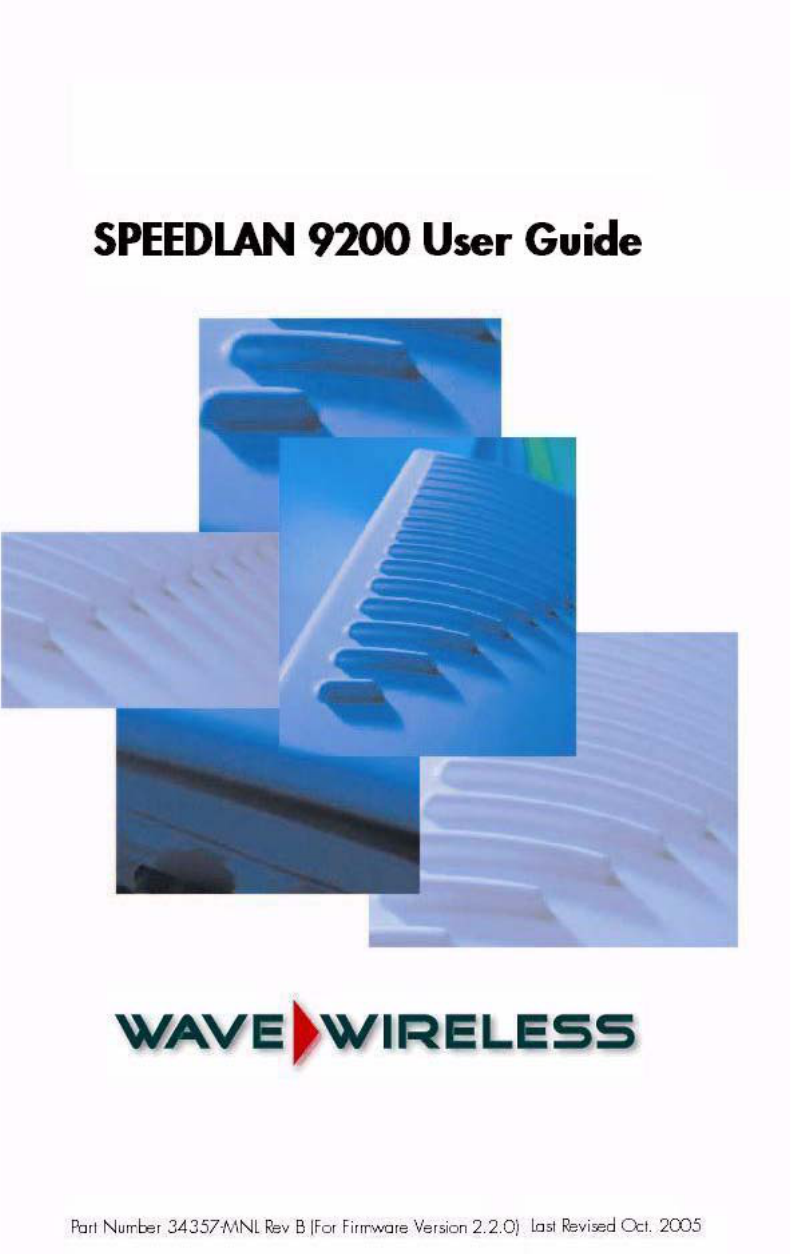
Figure 1-1: SPEEDView illustrating a mesh network (in SPEEDManage suite)
SPEEDLAN 9200 routers provide the unique ability to "self-heal" the wireless network as
the topography changes over time, thereby increasing the overall stability and
performance of the network while allowing traffic to reach buildings blocked by
obstructions of line-of-sight.
What is happening in Figure 1-1 on page 1-7?
•You will notice negative numbers next to the routers, or referred to as nodes on
the network diagram. These numbers represent the receive signal strength
(expressed as dBm) for the links in the network diagram.
•The black dots in a mesh network diagram indicate a trace route, which maps out
the current data flow between the selected pair of nodes. A user would select the
trace feature to view the data flow between a node pair (for mesh networks only).
This illustration also shows that every router in the mesh cell can be heard by
Part # 34357-MNL Rev. B SPEEDLAN 9200 User Guide
1-8
every other router in the cell, except for the blocked link indicating that there is
no signal between those two nodes.
SPEEDView allows you to block traffic over any link in the cell. When you block
a connection, the node pair will not be able to communicate. The advantage of
blocking a connection is verifying that the path can be re-routed for successful
connectivity. (This is done using the "Block" feature in SPEEDView. The broken
[or disconnected] link will appear as a red line. This link also appears when
there is no signal between two nodes.)
•SPEEDView can also be used to perform bandwidth, link and ping tests.
Routing Around Obstacles
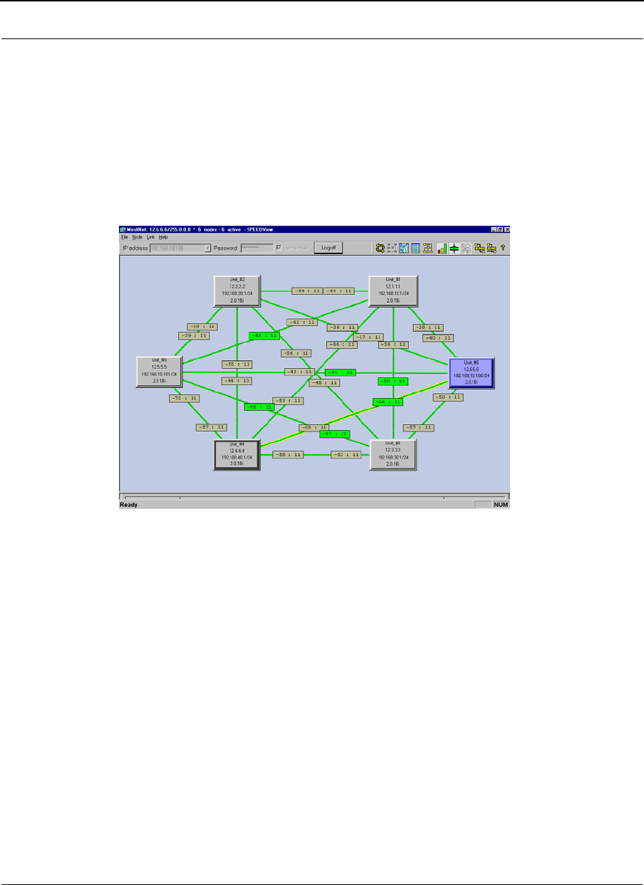
Figure 1-2: Routing around obstacles
Explaining this scenario on the simplest level (using the Mesh protocol as shown in
Figure 1-2 on page 1-8). A can route a packet to B, despite the tree obstruction (block of
trees) within the path. How does this procedure work?
1A has line-of-sight to C but not to B.
2C has line-of-sight to A and to B.
The most efficient path in this case is to hop from A to C to B.
Note: No manual programming is required because A automatically detects its
neighboring router (in this case C, and B and detect a clear path to C). Therefore, the
packet is successfully routed around the obstacle between B and A.
This process creates a more scalable, flexible, and extended wireless network (as shown
in Document Changes & Corrections/Firmware Updates, page 1-11).
Obstacle
A
E
B
C D
SPEEDLAN 9200 User Guide Part # 34357-MNL Rev. B
1-9
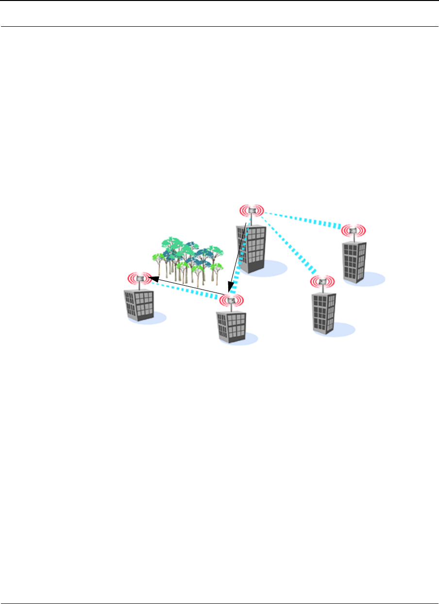
SPEEDLAN’s Mesh Cell Architecture
Specifically designed to meet the connectivity demands for everyone from single users to
large corporations, all SPEEDLAN 9200 models are equipped for mesh operation. These
models will communicate with every other mesh router within an unobstructed path.
Figure 1-3: An example of a mesh network
SPEEDLAN 9200 Mesh Core Components
SPEEDLAN 9200 Mesh protocol includes three central components which are neighbor
discovery, topology updates, and routing.
Neighbor Discovery
Neighbor discovery occurs when each router sends a broadcast "hello" message to detect
those routers to which it has line-of-sight. The "hello" sender acknowledges those replies,
whereupon the sender and the neighboring router add each other to their respective active
neighbor lists. Neighbor discovery protocol messages are sent by each router on startup
and periodically thereafter. The periodic messages are required to determine when a
former neighbor can no longer be reached, whereupon it is removed from the active
neighbor list. Neighbor discovery messages are relatively short and are sent infrequently
enough that they don't constitute significant overhead.
Topology Updates
When a router adds or deletes a neighbor to or from its active neighbor list, it propagates
that information to the rest of the routers in the wireless mesh LAN. Unlike classic wired
routing protocols, topology update notifications are not flooded. Instead they are sent via
a spanning tree, such that each router receives only one notification of a particular event.
(A brief explanation of the spanning tree algorithm is explained in the note below.) This
approach also conserves bandwidth for use in forwarding user traffic. Since each router

Part # 34357-MNL Rev. B SPEEDLAN 9200 User Guide
1-10
knows the topology of the entire wireless LAN, it can determine the shortest path to each
peer router in the wireless LAN.
Note: In short, the spanning tree algorithm enables units to dynamically locate a subset of
the topology that is loop-free. The spanning tree algorithm determines the best path a unit
can use to send a message.
Routing
Routing is simply the act of forwarding a received Internet Protocol (IP) datagram (a
block of data) toward its destination. The router compares the destination IP address to
entries in its routing table. If the destination is a wireless neighbor or a node connected to
the router's wired LAN, the router sends the datagram directly to the destination.
Otherwise, it sends the datagram to another router, which must be on the wired LAN or be
a wireless neighbor.
In wired broadcast LANs, all routers on the LAN can hear each other. Therefore, a
datagram only passes through a router when it is moving from one LAN to another LAN
along the path to its destination. In a mesh wireless LAN, not all routers can hear each
other. Therefore, a router within a wireless LAN may forward a datagram to a neighbor
router within the same wireless LAN, in order to send the datagram toward its destination.
For each datagram, the routing algorithm minimizes the number of router-to-router hops
within the wireless LAN, thereby also conserving bandwidth for other user traffic.
Why SPEEDLAN Outperforms Other Routing Equipment
The SPEEDLAN 9200 outperforms other routers because the SPEEDLAN 9200 routing
table broadcasts only the information that changed, such as when new routes are added or
old routes are removed from the network. This information is sent to the router's
immediate neighbors along the most efficient path to the end destination. This process
helps conserve bandwidth. If an existing path is modified in some way, by the addition or
deletion of a router, a SPEEDLAN 9200 using the Mesh protocol can monitor its routing
table to decide if a secondary path should be taken. One could call this a "self-healing"
network, which means it finds a secondary route through the network without manually
reprogramming the routers.

SPEEDLAN 9200 User Guide Part # 34357-MNL Rev. B
1-11
Document Changes & Corrections/Firmware Updates
Documents Changes & Corrections
•Added IC (Canada) and ETSI channels in Channel Frequency Appendix, F-2 for
certified channels 1-11.
•Added 12 dBm (13mW) under 5GHz column in Table 3-3, “TX Power List,” on
page 3-46.
Firmware Updates
The most current version of firmware is Version 2.2.0
This section informs the customer about new features and requirements for the
SPEEDLAN 9200 firmware.
Bug Fixes:
None
Known Problems:
None
CHANGES PRIOR TO THIS RELEASE CAN BE FOUND IN Firmware History, Appendix
E-1 OF THE SPEEDLAN 9200 USER GUIDE.
Contacting Technical Support
408-943-4202 (phone)
408-943-4355 (fax)
Note: Registered customers should check our web site on a regular basis for updates,
router firmware, SPEEDView, and other utility programs. If you haven't registered your
products yet, you may do so by visiting www.p-com.com.

Part # 34357-MNL Rev. B SPEEDLAN 9200 User Guide
1-12

Chapter 2
SPEEDLAN 9200
Hardware

Part # 34357-MNL Rev. B SPEEDLAN 9200 User Guide
2-2
Rooftop and Tower Installations Warning
Rooftop, tower, and other mounted location equipment installations are extremely
dangerous and incorrect installation can result in property damage, injury or death.
Regulatory Information
Install this device in accordance with the instructions provided in this User Guide. To
determine the type of device you should use in your country, see the Radio Approval Table
Radio Approvals, Appendix C-4.
This equipment has been tested and found to comply with the limits of a Class B digital
device, pursuant to Part 15 of the FCC Rules. Additionally, the equipment is certified to
operate under Part 90, Subpart Y of the FCC rules to operate as a high power device in
the 4.9 GHz PSB band with 5, 10, and 20 MHz channel bandwidths. These limits are
designed to provide reasonable protection against harmful interference when the
equipment is operated in a residential environment. This equipment generates, uses, and
radiates radio frequency energy, and if not installed and used in accordance with the
instructions, may cause interference. If this equipment does cause interference to radio or
television reception, which can be determined by turning the equipment off and on, the
installer should correct the interference by one of the following measures:
•Reorient or relocate the receiving antenna.
•Increase separation between the equipment and receiver.
•Connect the equipment into an outlet on a circuit different from which the
receiver is connected.
•Consult the professional installer or an experienced radio/TV technician.
Note: The manufacturer is not responsible for any radio or TV interference caused by
unauthorized modifications to this equipment. Such modifications could void the user’s
authority to operate the equipment.
!
!
SPEEDLAN 9200 User Guide Part # 34357-MNL Rev. B
2-3
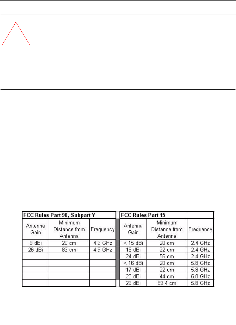
Warning! This radio device operates on a non-interference basis with other devices
operating at this frequency when using the following antennas:
• The Part 15 device mode at
•2.4GHz: 12dBi external omni or 24dBi directional grid antenna.
•5.8GHz: 10dBi external omni antenna. The 29dBi directional dish antenna
or 23dBi sector flat panel antenna may only be used with filter .
•The Part 90 device mode at 4.9 GHz may be used with a 9 dBi omni or 26
dBi directional antenna.
Declaration of Conformity for RF Exposure
The radio module has been evaluated under FCC Bulletin OET65C and found compliant
to the requirements as set forth in CFR 47 Sections 2.1091, 2.1093, and 15.247 (b) (4)
addressing RF Exposure from radio frequency devices. The radiated output power of this
wireless LAN device is far below the FCC radio frequency exposure limits. Nevertheless,
this device shall be used in such a manner that the potential for human contact during
normal operation is minimized. When using this device, a certain separation distance
between the antenna and nearby persons must be maintained to ensure RF exposure
compliance. In order to comply with RF exposure limits established in the ANSI C95.1
standards, the distance between the antenna and your body or nearby persons should not
be less than:
!

Part # 34357-MNL Rev. B SPEEDLAN 9200 User Guide
2-4
General Safety Requirements for Installation of SPEEDLAN
9200 Models
1The AC power socket outlet should be installed near the switching power
supply and junction box.
2It is recommended that replacement of the battery which is soldered to the PC
board should be done by manufacturer or professional installer.
CAUTION: THERE IS RISK OF EXPLOSION IF BATTERY IS REPLACED BY
INCORRECT TYPE. DISPOSE USED BATTERIES ACCORDING TO
INSTRUCTIONS.
3During installation of SPEEDLAN 9200 on a tower, pole or wall,
the necessary clearance from the power and lightning conductors should be
maintained and proper grounding provided. The installation should be done in
accordance with National Electrical Code:
•NEC Article 725 – CEC Rule 16
•NEC Article 800 – CEC Section 60 and
•NEC Article 810 – CEC Section 54.
Hardware Overview
The SPEEDLAN 9200 offers all the equipment you need to meet your connectivity
requirements:
•SPEEDLAN 9201: A router used in a non-line-of-sight pico cell (using the Mesh
protocol). This router contains an integrated 8 dBi, omni antenna (for 2.4 GHz
only) which is directly attached on the top. You do not need an
additional external antenna. The parameters are configured with the Mesh proto-
col in the SPEEDLAN 9200 Configurator. This type of self-healing Mesh topol-
ogy process helps you reach buildings that do not have a clear line-of-sight back
to a base station without the possibility of interference from hidden transmitters.
For more information on this topic, see SPEEDLAN 9200 Mesh Protocol -- How
It Works in Mesh Cells, page 1-6.
•SPEEDLAN 9202: This model can be configured as Customer Premise
Equipment (CPE) at one end of the point-to-point or point-to-multipoint link. It
can be used with a 2.4GHz or 5.8GHz external antenna.
•SPEEDLAN 9203: This model is pre-configured as a base station but can be
reconfigured to function as a CPE router or as one end of a point-to-point or
SPEEDLAN 9200 User Guide Part # 34357-MNL Rev. B
2-5
point-to-multipoint link. It can be used with a 2.4GHz or 5.8GHz external
antenna.
•SPEEDLAN 9204: This model provides the same functionality as a SPEEDLAN
9201, but it uses an integrated 5 dBi omni (for 2.4GHz only). The SPEEDLAN
9204 is intended for more densely populated cells.
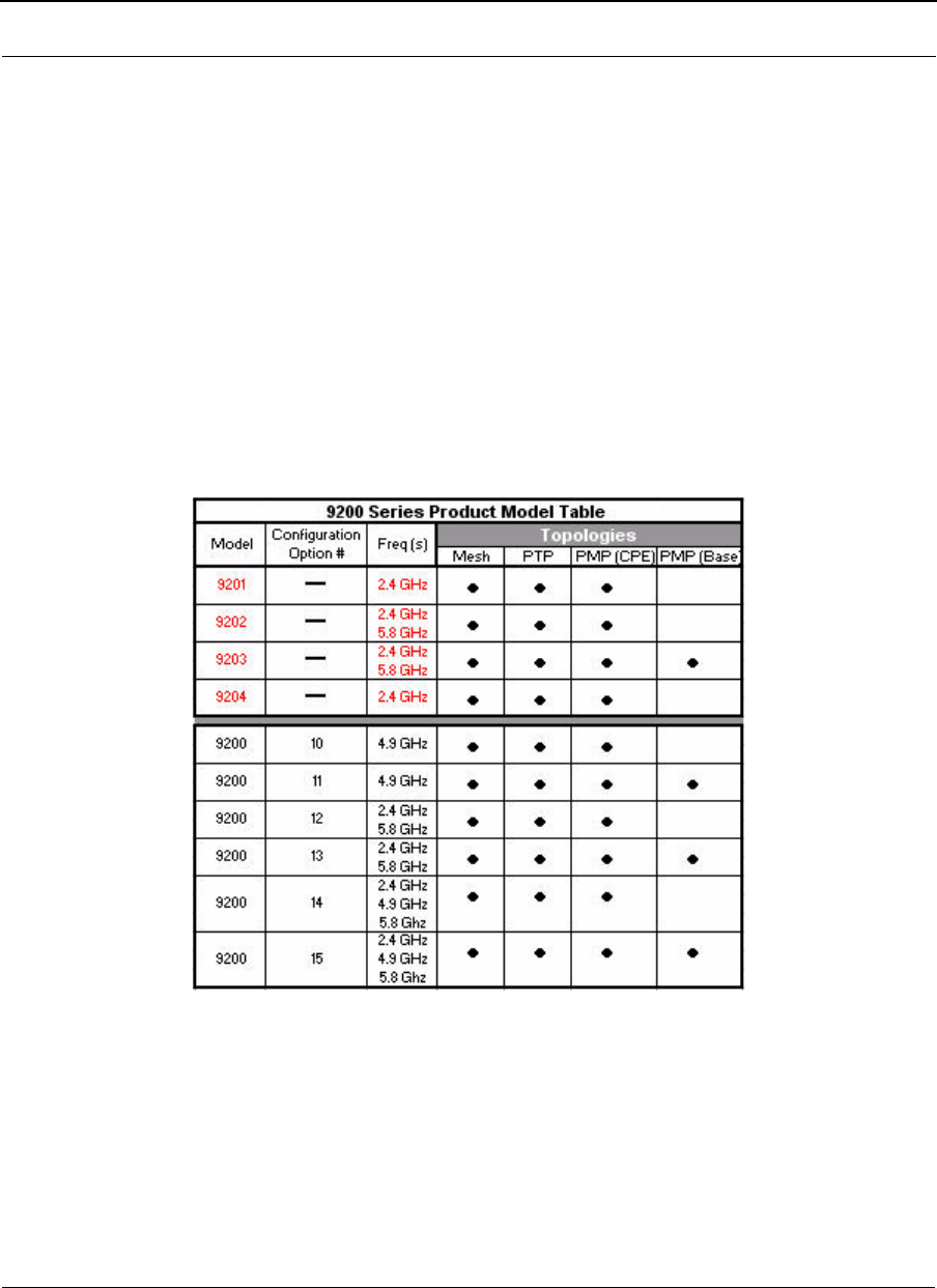
•SPEEDLAN 9200 (Option #10-15): This is the new model numbering format.
The Option # identifies the router’s topology capabilities. See the following
Table 2-1.
Table 2-1: 9200 Topology Configuration Table
As of October 2005, the model numbering format changed. The new model numbering
format uses a Configuration Option # to distinguish different models.
The SPEEDLAN 9200 is housed in a waterproof, cast enclosure that mounts outside the
building, on a mast, or tower. The SPEEDLAN 9200 allows up to 300’ of specialized,
outdoor Ethernet cable to be used between the LAN and the RF device, without loss of any
radio signal. This increases the effective wireless link distance and reduces or even
eliminates the need for an amplifier.
Part # 34357-MNL Rev. B SPEEDLAN 9200 User Guide
2-6
Tips for Antenna Alignment
You are encouraged to use the transmit power test during installation if you have a
spectrum analyzer or power meter to measure the output for the antenna alignment. For
more information, see the SPEEDManage User Guide. The SPEEDSignal application will
also help installers align or position antennas on SPEEDLAN 9200 units.
Drawings of Outdoor, Remote-Mounted Components
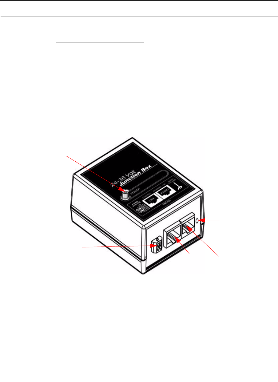
Indoor Junction Box
Figure 2-1: Indoor junction box for SPEEDLAN 9200
WARNING!: Make sure the network is plugged into the LAN interface, and that the radio
is plugged into the radio interface. If you do this procedure wrong, the voltage that is
meant to go to the radio can damage a device on the network.
When the green light is illuminated,
the DC voltage is being injected
DC jack to external power supply To LAN To Radio
Grounding - Ground
the wire to the nearest
earth ground. Indoor
ground plug will be
installed here.
SPEEDLAN 9200 User Guide Part # 34357-MNL Rev. B
2-7
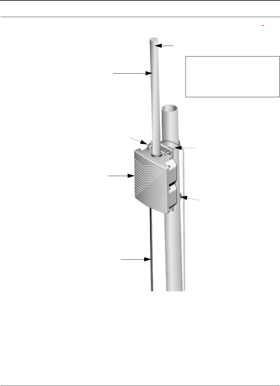
SPEEDLAN 9201/9204 with an Integrated Omni-Directional Antenna
Figure 2-2: SPEEDLAN 9201/SPEEDLAN 9204 installation
The installation steps for the SPEEDLAN 9201 and SPEEDLAN 9204 are similar, but the
SPEEDLAN 9201 uses a larger omni and the SPEEDLAN 9204 uses a smaller omni-
directional antenna.
Integrated
outdoor CAT5 cable to
*Pole/tower leg
Grounding wire (optional)
junction box
V-bolt
Router
omni
V-bolt
*Note: The minimum outside
diameter of the pole is 1.25 inches.
The maximum outside diameter
of the pole is 2.5 inches.
to appropriate outdoor
ground
Part # 34357-MNL Rev. B SPEEDLAN 9200 User Guide
2-8
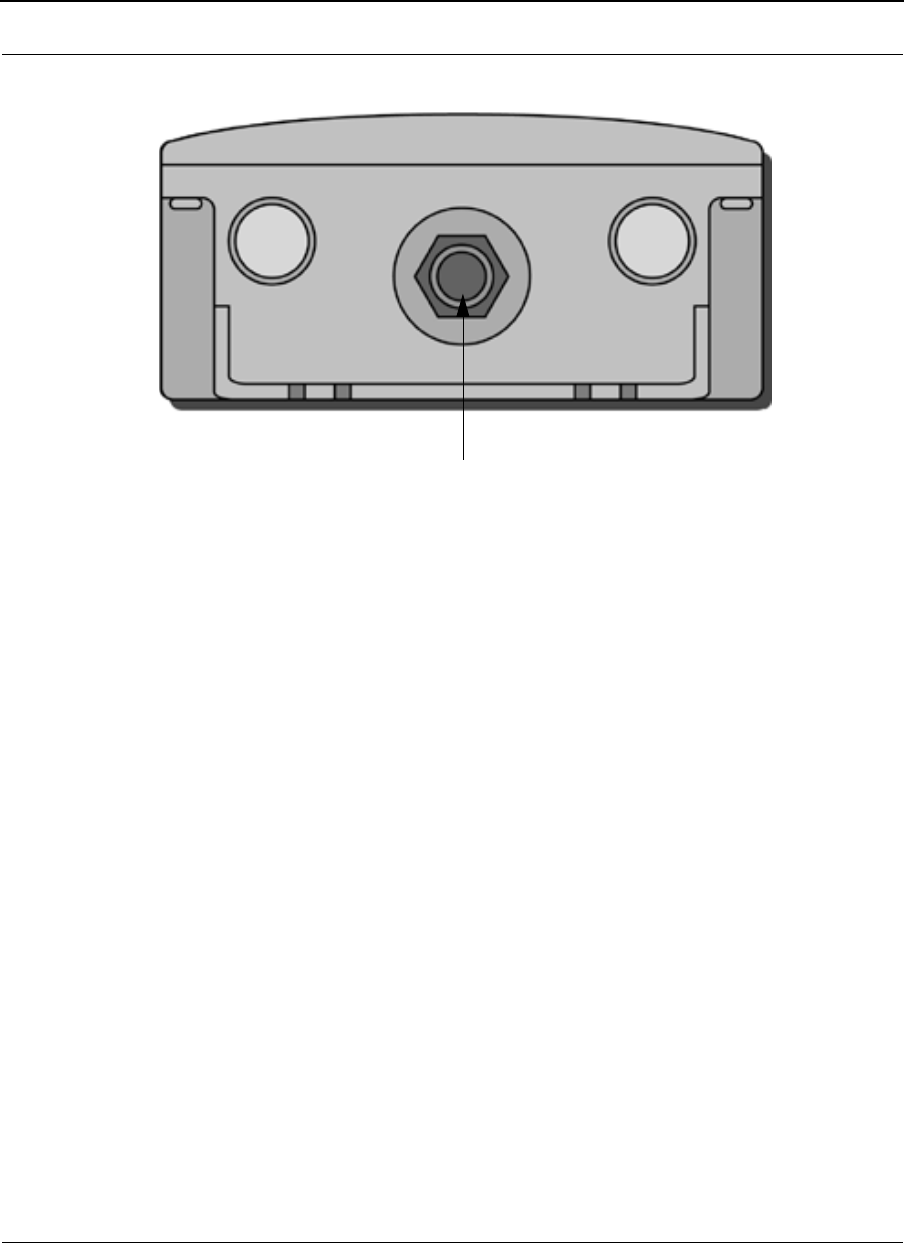
Bottom View of SPEEDLAN 9201/SPEEDLAN 9204
Figure 2-3: Bottom view of case
System Description
These are high-speed, long range wireless LAN outdoor, remote-mounted units/routers
that provide building-to-building connectivity in a mesh cell.
Package Contents
•SPEEDLAN 9201 or SPEEDLAN 9204
•CD containing: Adobe Acrobat Reader, SPEEDManage software & User Guide,
this User Guide, Installation Diagram booklet and Getting Started Guide
•Indoor junction box
•Power supply
•Integrated, omni-directional antenna
•V-bolt kit which includes the following
•Bolt, V, Tower Mount, Stainless Steel (quantity 2)
•Nut, 1/4"-20, Serrated Flange, Stainless Steel (quantity 4)
•V-Bracket, Tower Mount, Aluminum (quantity 2)
The following items are included with the installation kit, which can be purchased
separately:
Power/Ethernet (CAT5 down to junction box)

SPEEDLAN 9200 User Guide Part # 34357-MNL Rev. B
2-9
•Hardware ties
•Specialized CAT5 cable
Customer Sourced / Other
•Combination wrench or socket wrench (7/16") to tighten the nuts on the V-bolts
(customer sourced only)
•Other tool accessories that can be purchased separately from Wave Wireless are:
cable, connectors, crimpers, spectrum analyzer, shrink wrap, putty, aluminum 2"
pole, extendable mast, ballast mount, peak roof mount, extra v-bolts, nuts,
grounding rod clamps, wall mounts
Installation Steps for the SPEEDLAN 9201/SPEEDLAN 9204
To install your SPEEDLAN 9201/SPEEDLAN 9204, follow the steps below:
Step 1: Mounting the SPEEDLAN 9201/SPEEDLAN 9204
This router will have an omni directly attached. No additional steps are needed for this
step. Go to Step 2.
Step 2: Mounting the SPEEDLAN 9201/SPEEDLAN 9204 on the Pole
•Pole Mount: Attach the router to the mounting pole using the two V-bolted
clamps and aluminum bracket, one on top of the router and the other on the bot-
tom of the router. Make sure you tighten the nuts for the clamps securely to pre-
vent shifting of the router after antenna alignment.
Step 3: Running the Cabling
1Run outdoor CAT5 cable (from bottom of router) down to junction box located
inside the building.
2Secure grounding wire by running this wire to a suitable "earth" ground and fas-
ten it securely in place. See the installation diagram following
these directions.
3Install proper indoor ground plug into the junction box. Connect the outdoor
CAT5 Ethernet to the "radio" jack. Connect the LAN Ethernet cable to the "LAN"
jack of the junction box. Install the power supply DC connector to the junction
box. Plug the external power supply into the wall outlet.
(The VAC power outlet’s input voltage of this universal adapter can vary from
100 to 250 VAC.) Connect the DC output of the adapter to DC jack on the indoor
junction box.

Part # 34357-MNL Rev. B SPEEDLAN 9200 User Guide
2-10
4 Connect the wireless SPEEDLAN 9201/SPEEDLAN 9204 to the customer's
Ethernet LAN or PC by connecting the RJ-45 plug on a standard Ethernet CAT5
cable to the RJ-45 port connector, marked as "LAN" on indoor junction box.
Connect the other end of the Ethernet CAT5 cable to your Ethernet hub, switch or
router.
Important Note: Waterproofing the External Connectors!
Make sure you waterproof all the connectors, as follows: Apply two layers of electrical
tape to the connector (covering three inches of cable past the connector), and leave
approximately 3 inches of cable exposed on either side of the connector. An alternative is
to begin at the lowest point, so the tape overlaps from bottom to top creating a shingled
effect. (This creates an effective barrier against runoff.) Apply this "shingle effect" to each
layer of the sealing process. Then, apply one layer of insulation putty over the top of the
electrical tape, and leave at least one inch of the cable jacket to ensure a good seal. Do
not stretch the putty, as this causes thinning and reduces the effectiveness of a good seal.
Finally, apply five layers of electrical tape over the insulation putty and extend at least
one (1) inch past the putty. This is the most important step in a creating a watertight seal.
Make sure that there are no wrinkles in the tape, and the final wrap must be completed
from bottom to top.
SPEEDLAN 9200 User Guide Part # 34357-MNL Rev. B
2-11
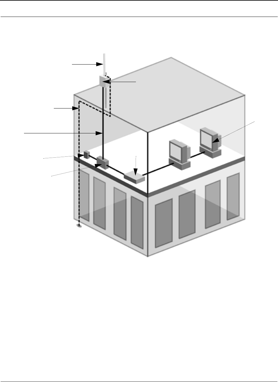
Installation Diagram of the SPEEDLAN 9201/SPEEDLAN 9204
The diagram below displays where the main components are located for the SPEEDLAN
9201/SPEEDLAN 9204 with an integrated omni.
Figure 2-4: SPEEDLAN 9201/SPEEDLAN 9204 installation diagram
Note: Routers purchased and/or labeled as SPEEDLAN 9200 with Configuration
Option # 10, 11, 12, 13, 14, or 15, please follow all hardware and installation instruc-
tions for the SPEEDLAN 9202/SPEEDLAN 9203 products listed in this manual.
Antenna
(Integrated
omni)
Router
Grounding wire
Cable with
combined Ethernet
and DC voltage
AC wall outlet
Junction box
Ethernet / hub
Ethernet
or switch
to appropriate outdoor
ground
Part # 34357-MNL Rev. B SPEEDLAN 9200 User Guide
2-12
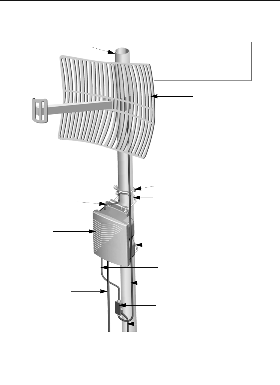
SPEEDLAN 9202/SPEEDLAN 9203/SPEEDLAN 9200 (Option
# 10-15) using External Antenna
Figure 2-5: SPEEDLAN 9202/SPEEDLAN 9203/SPEEDLAN 9200 (Option # 10-15) installation
External antenna
V-bolt
V-bolt
Lightning arrestor
10’ cable
3’ pigtail
Grounding wire
outdoor CAT5 cable to
junction box
*Pole/
tower leg
Grounding wire
Grounding clamp
Router
*Note: The minimum outside
diameter of the pole is 1.25 inches.
The maximum outside diameter
of the pole is 2.5 inches.
to appropriate outdoor
ground
SPEEDLAN 9200 User Guide Part # 34357-MNL Rev. B
2-13
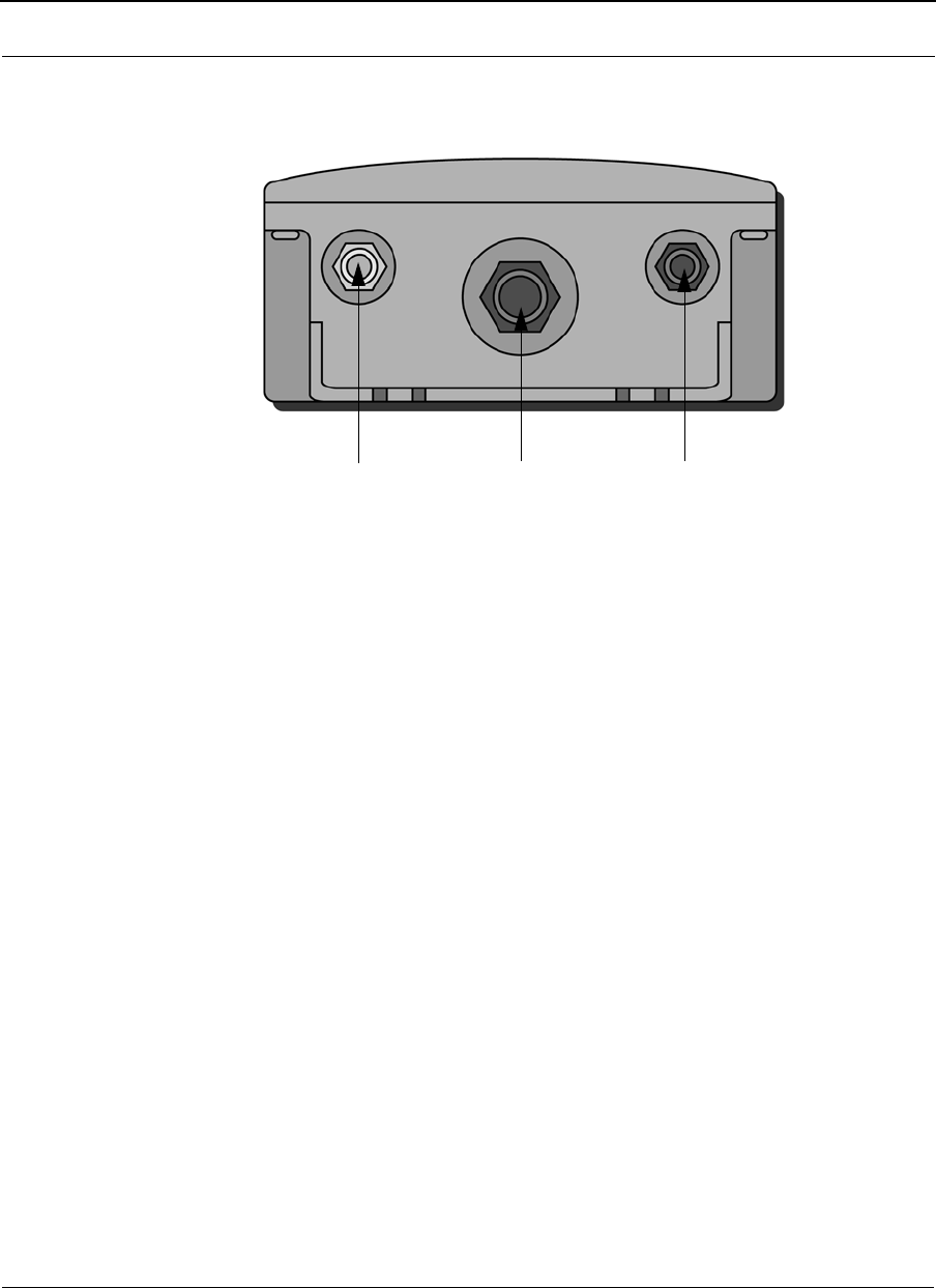
Bottom View of SPEEDLAN 9202/SPEEDLAN 9203/SPEEDLAN
9200 (Option #10-15)
Figure 2-6: Bottom view of case
System Description
The SPEEDLAN 9202/SPEEDLAN 9203/SPEEDLAN 9200 (Option #10-15) routers are
high speed, long range wireless LAN routers that provide connectivity to remote Ethernet
networks.
Package Contents
The following items are included in the package contents:
•SPEEDLAN 9202, SPEEDLAN 9203, or SPEEDLAN 9200 (Option #10-15)
router
•CD containing: Adobe Acrobat Reader, SPEEDManage software & User Guide,
this User Guide, Installation Diagram booklet and Getting Started Guide
•Indoor junction box
•3’ pigtail
•V-bolt kit which includes the following
•Bolt, V, Tower Mount, Stainless Steel (U-bolt) (quantity 2)
•Nut, 1/4"-20, Serrated Flange, Stainless Steel (quantity 4)
•V-Bracket, Tower Mount, Stainless Steel (quantity 2)
•Power supply
Input/Output DC Output to Amp
Power/
RTNC RF Ethernet
(RF Signal)

Part # 34357-MNL Rev. B SPEEDLAN 9200 User Guide
2-14
The following items are included with the installation kit, which can be purchased
separately:
•Hardware ties
•Lightning arrestor
•Electrical tape
•Waterproof putty tape
•Specialized CAT5 cable
•10’ RF cable
•Grounding rod clamps
*Note: Antennas for the router are purchased separately. Using an antenna whose gain
is greater than +17dBi at 5.8 GHz will require the use of an external RF Filter to be
installed between the RF Output of the router and the RF Input to the antenna. (See the
installation drawing on page 2-18)
Customer Sourced / Other
•Combination wrench or socket wrench (7/16") to tighten the nuts on the V-bolts
(customer sourced only)
•Other tool accessories that can be purchased separately from Wave Wireless
are: cable, connectors, crimpers, spectrum analyzer, shrink wrap, putty, alumi-
num 2" pole, extendable mast, ballast mount, peak roof mount, extra v-bolts,
nuts, grounding rod clamps, wall mounts
Installation Steps for the SPEEDLAN 9202/SPEEDLAN 9203/
SPEEDLAN 9200 (Option #10-15)
Generally, these routers follow the same general installation steps. Some installation
instructions are specific to customers who purchased Installation Kits from Wave Wireless.
To view a diagram of the installation listed below, see Figure 2-9 on page 2-21.
If you are having trouble and need a full site installation, contact Wave Wireless for
services and fees.
Antenna Selection Tip: Use a high-gain omni or sectoral antenna for a base station
(SPEEDLAN 9203), and use a grid or directional antenna for a CPE or point-to-point
router (SPEEDLAN 9202).
SPEEDLAN 9200 User Guide Part # 34357-MNL Rev. B
2-15
To install your router with an external antenna, do the following:
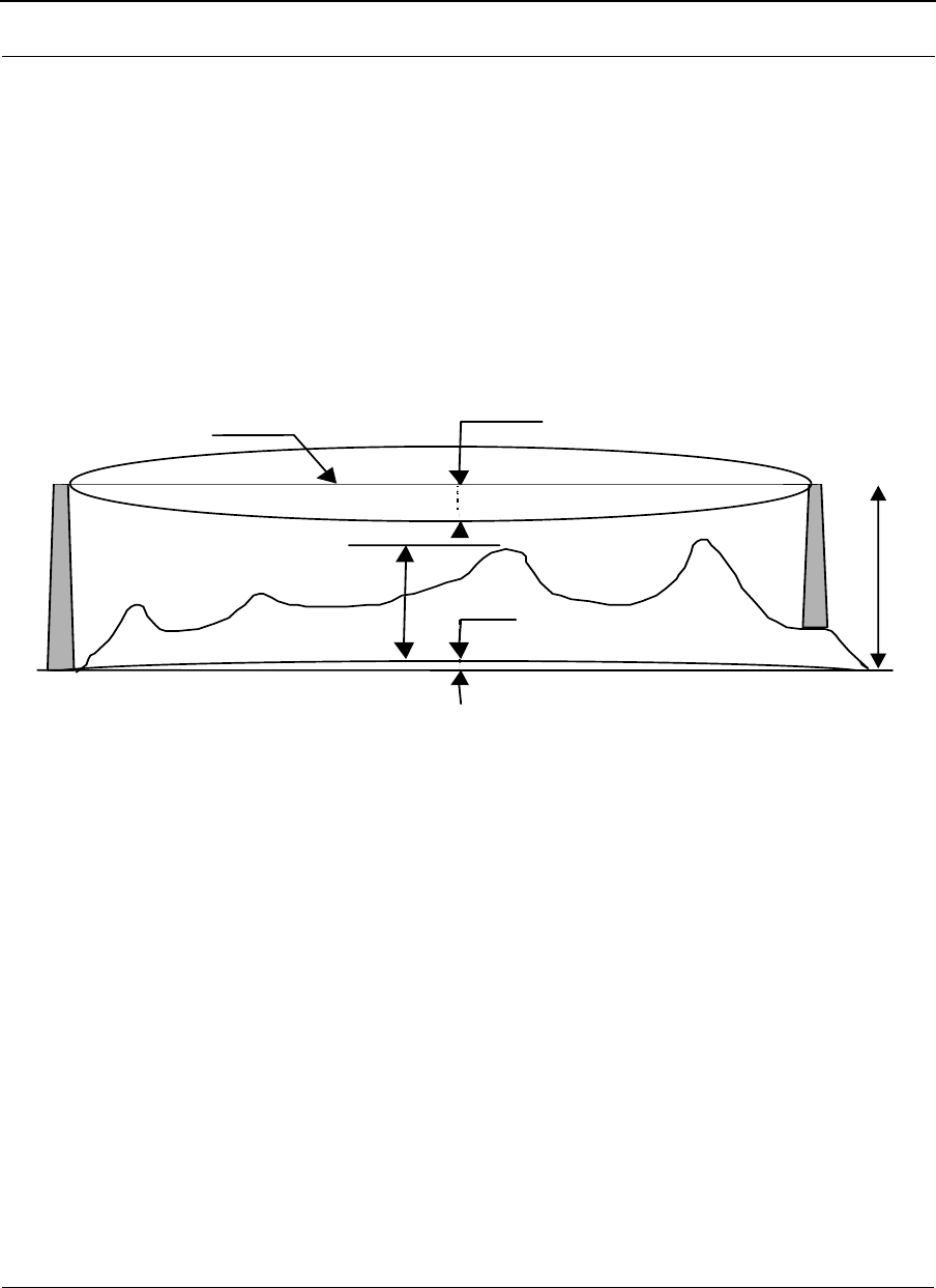
Step 1.Verifying Line-of-Sight
Before installing the antenna and router, make sure a clear line-of-sight exists between the
two points. Line-of-sight can be defined as each antenna clearly seeing the other antenna,
and seeing the remote locations when viewing from the central base location. Be sure to
look at the center of origin of the transmission (i.e., the middle of the antenna). Repeat this
procedure from the remote location. Any disruption of the signal path due to trees,
building, or any other obstructions may cause the link to function incorrectly. Make sure
at least 60 percent of the RF signal is unobstructed by any path blockages.
Figure 2-7: Line-of-sight (LOS) diagram
Note: For long distances, additional antenna height is often required to overcome signal
diffraction and to provide clear Radio LOS. For Radio LOS, a clear Fresnel
(Freh-nel) zone is required to minimize diffraction effects. The Fresnel zone is shaped like
an elongated football. The most clearance is required at the mid-point between the two
sites.
Beyond approximately 10 miles, the curvature of the earth can also become significant. At
these longer distances, visually sighting the remote site can be difficult or impossible due
to atmospheric haze. Terrain data (map or differential GPS) must be relied upon for
determining path clearance. Elevation data determined with these methods is above Mean
Sea Level; and does not account for curvature of the earth. Both the curvature of the earth
and the Fresnel clearance numbers can be combined to determine the additional
clearance required above any natural or man-made obstructions along the path.
Visual Line of
Si ht
Fresnel Zone
di t
Obstruction
Hiht
A
bove Mean Sea
Ll)
Earth
t
Tower
Hiht
A
bove
MSL)

Part # 34357-MNL Rev. B SPEEDLAN 9200 User Guide
2-16
Obtaining this clearance can be accomplished by raising the antenna height at one or
both sites. If this is not practical, then consider relocating one or both sites to locations
with higher elevations. Another option is to add a third site to go over or around the
obstacle.
If you see any obstructions between two antennas, move one or both antennas to another
location.
Step 2. Mounting the Antenna
Follow the instructions below to mount the antenna.
a On a side-building mount, position the bracket so there will be at least three feet
(one meter) above the roof line where the pole is attached. This enables room for
the antenna and reduces signal loss from building reflection.
Note: It is not recommended to mount the antenna onto any unstable object.
bAllow for as much space between the wall brackets as possible while
maintaining the appropriate antenna height. For extended poles, additional wall
brackets may be necessary.
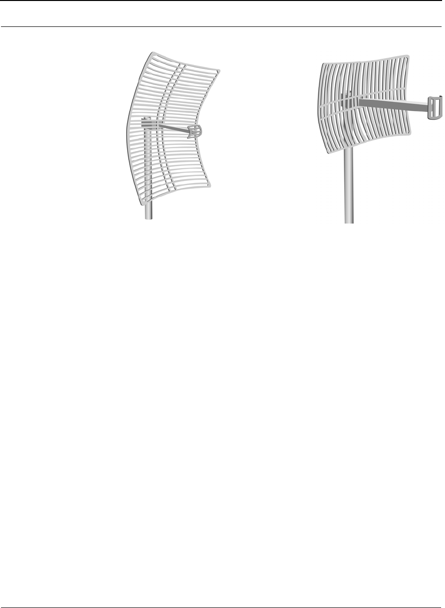
cAssemble the antenna and mount it to the pole using the included V-bolt antenna
mounting hardware. For a semi-parabolic grid type antenna, align the grid to
run parallel with the grid on the tip of the antenna horn.
A horizontal grid should be horizontal (or parallel to the ground). A vertical grid
should be perpendicular to the ground. Make sure all bolts and screws are fas-
tened tightly.
SPEEDLAN 9200 User Guide Part # 34357-MNL Rev. B
2-17
See also Tips for Antenna Alignment, page 2-5.
Figure 2-8: Grid antennas
dFasten the pole to the brackets. Position the antenna, point it in the
appropriate direction, and tighten the screws. Then, aim the antenna so it is
pointed toward the receiving antenna on the other building. The radio signal
radiates from the end of antenna like a wide-beamed flashlight. For optimal per-
formance, you may need to test your link using both horizontal and
vertical-oriented polarities. This configuration option varies with each location,
as well as RF signals that may be present in the area.
Step 3. Mounting the SPEEDLAN Router
Select one of two options below:
•Option A: Pole Mount
On a pole mount, position the router 5 to 10 feet below the antenna. Then, attach
the router to the mounting pole using two included V-bolt clamps, one on the top
of the router and the other on the bottom. Make sure you tighten the nuts for the
clamps on the back of the pole mount.
OR
Horizontal-Oriented Grid Vertical-Oriented
Grid

Part # 34357-MNL Rev. B SPEEDLAN 9200 User Guide
2-18
•Option B: Wall or Concrete Mount
On a side building mount, position the router 5 to 10 feet below the antenna.
Then, attach the SPEEDLAN router to the wall or concrete by using the
concrete or wood mounting screws. Make sure it is securely mounted on the wall.
Step 4. Running and Securing All Cable
The installation kit includes two cables with ready-made connectors to fit your particular
installation needs such as:
•3’ RF cable
•10' antenna cable (attaches to antenna one end and to lightning arrestor other
end)
•Lightning arrestor (attaches to pigtail and to antenna cable)
aAttach the 3’ RF cable to the RF port on the router.
bAttach the 10' length of cable to the antenna. Next, attach the lightning
arrestor to the lower end of the antenna cable.
cAttach the other end of lightning arrestor to 3’ RF cable.
dRun the main length of the specialized outdoor Ethernet cable from the router to
the indoor junction box located inside the building.
eSecure the cable (i.e., to the pole) with zip ties or cable clamps during this
procedure.
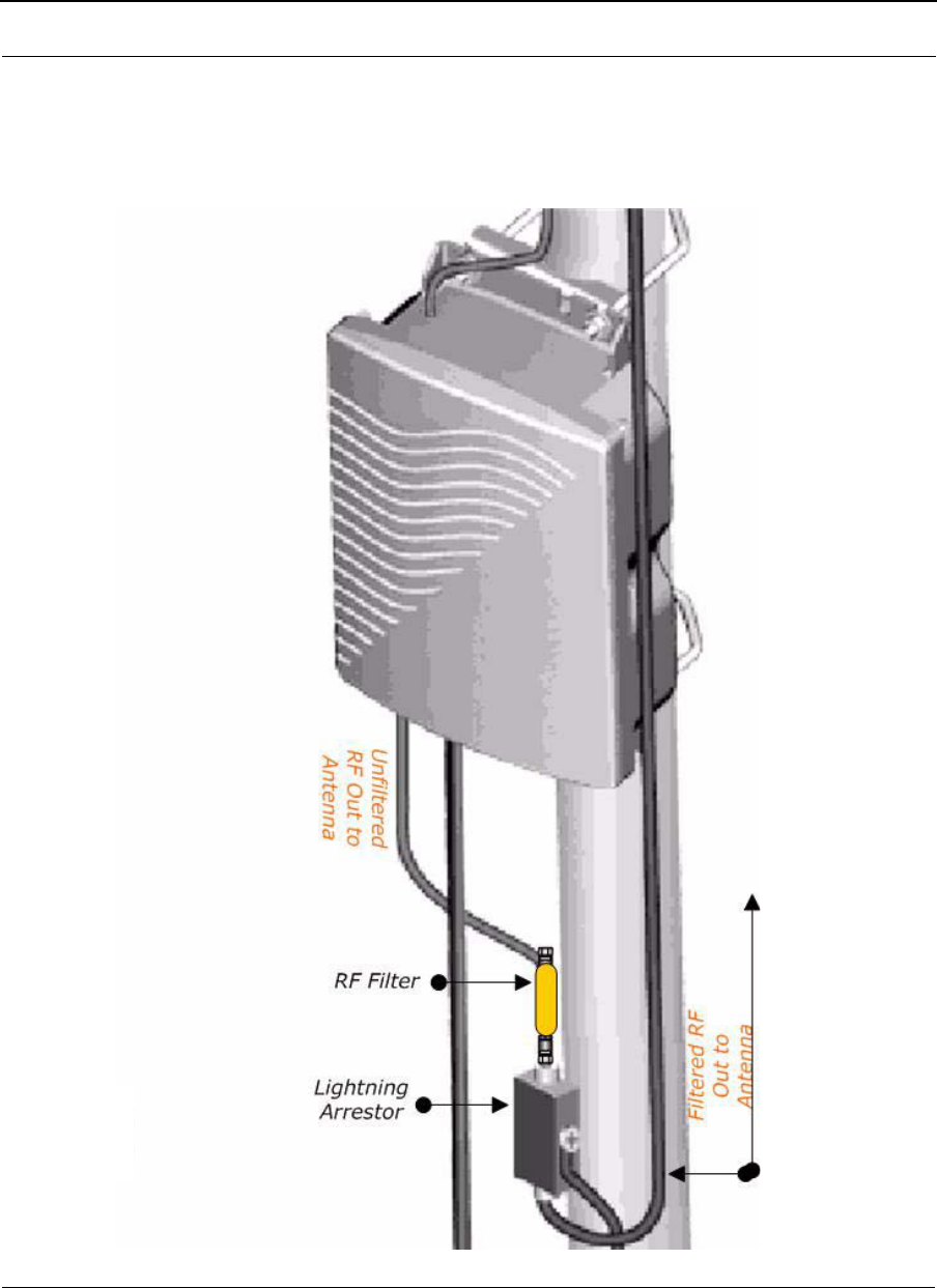
SPEEDLAN 9200 User Guide Part # 34357-MNL Rev. B
2-19
fDon’t forget: If your installation requires the use of an RF Filter because you
plan to transmit at 5.8 GHz using an antenna whose gain is greater than +17dBi
as mentioned in the note at the bottom of page 2-11, then you will install the RF
filter between the RF output of the router and the RF input of the antenna.

Part # 34357-MNL Rev. B SPEEDLAN 9200 User Guide
2-20
Note: When running the cable through walls or obstructions, make sure that there is ample
room for the connector to pass through the opening without being damaged. Also, do not
create extra pressure that would cause the cable to kink or be stretched or cut (i.e., pulling
cable through tight locations).
gCreate a proper weatherproofing seal on all outdoor connections by wrapping it
with electrical tape and sealing it with putty. This is the most crucial step of the
installation. If this procedure is not completed, long-term and complex problems
could occur. For more information on implementing this procedure, see Weather-
proofing Connectors, page 2-19.
hNext, ground the lightning arrestor. For more information, see Grounding the
Lightning Arrestor, page 2-19. You can also ground the router case to the ground,
as shown in the installation diagrams in this chapter.
Step 5. Grounding the Lightning Arrestor
aMount the lightning arrestor to a solid surface.
bRun the grounding wire from the lightning arrestor to a proper ground source
such as a grounding rod or roof ground wire. The lightning arrestor is NOT
waterproof. The next series of steps will show you how to effectively seal the
lightning arrestor and its cables.
Step 6. Weatherproofing Connectors
aSeal the entire lightning arrestor with the black waterproof sealant insulation
putty that is included in the installation kit.
bApply two layers of electrical tape to the connector, and leave approximately 3
inches of cable exposed on either side of the connector. An alternative is to begin
at the lowest point, so the tape overlaps from the bottom, below the
bottom connector over the lightning arrestor and beyond the upper connector, to
top creating a shingled effect. (This creates an effective barrier against water
runoff). Apply this "shingle effect" to each layer of the sealing process.
cApply one layer of insulation putty over the top of the electrical tape, and leave at
least one inch of the cable jacket to ensure a good seal. Do not stretch the putty,
as this causes thinning and reduces the effectiveness of a good seal.

SPEEDLAN 9200 User Guide Part # 34357-MNL Rev. B
2-21
dApply five layers of electrical tape over the insulation putty and extend at least
one (1) inch past the putty. This is the most important step in creating a
watertight seal. Make sure that there are no wrinkles in the tape and the final
wrap must be completed from bottom to top.
Step 7. Connect the Router to Customer's Ethernet LAN
aConnect the RJ-45 connector on a standard Ethernet CAT5 cable to the "LAN"
RJ-45 port on the indoor junction box.
bConnect the other end of the Ethernet CAT5 cable to your Ethernet hub, switch or
router.
Step 8. Connect the Wireless Router to the Power Supply
aConnect the DC output of the adapter (24-36 Vdc) to DC jack on the indoor
junction box.
bConnect power cord of AC-DC 24-36 Vdc adapter to 110 or 220 VAC power
outlet (the input voltage of this universal adapter can vary from 100 to 250 VAC).
Step 9. Adding Additional Routers
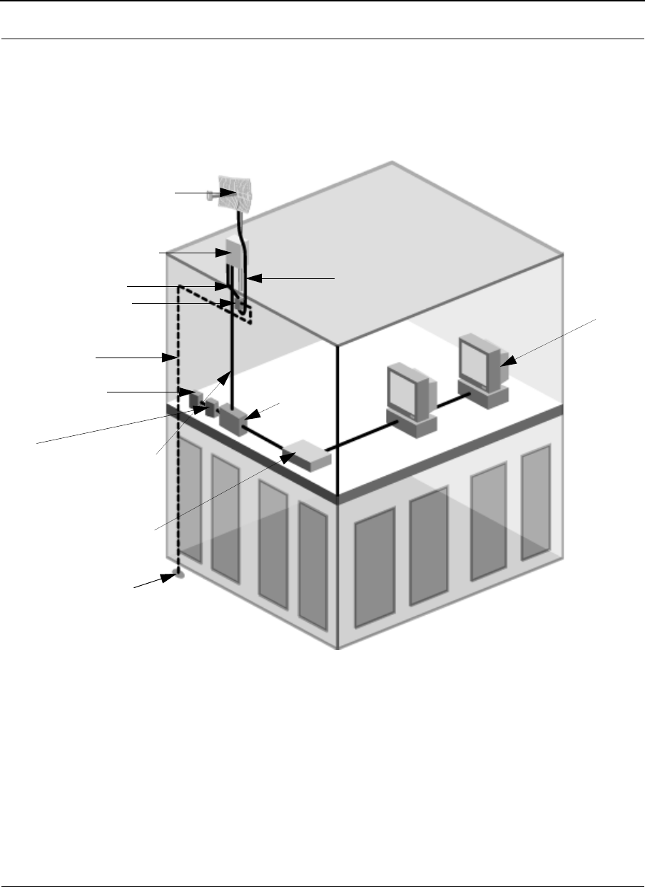
Part # 34357-MNL Rev. B SPEEDLAN 9200 User Guide
2-22
Repeat the steps above for SPEEDLAN 9202/SPEEDLAN 9203/SPEEDLAN 9200 (Option
#10-15) routers that will be communicating with this one.
SPEEDLAN 9202/SPEEDLAN 9203/SPEEDLAN 9200 (Option
#10-15) Installation Diagram
Figure 2-9: SPEEDLAN 9202/SPEEDLAN 9203/SPEEDLAN 9200 (Option #10-15) installation diagram
*Note: The sectoral, grid (directional) and high-gain omni antennas all follow the same
installation instructions.
You can ground the router case to the ground. You can ground the lightning arrestor as
well.
Router
3’ cable
Lightning arrestor
Grounding wire
AC wall outlet
Ethernet
Ethernet
10’ cable
*Antenna
(e.g., grid,
Junction
box
Cable with
combined Ethernet
and DC voltage
sectoral or
high-gain omni)
hub/
switch
Power
supply
Ground
to appropriate outdoor ground

Chapter 3
General Functions of the
Configurator
This chapter covers general functions when configuring any
SPEEDLAN 9200 router, such as:
•General Information: Manual Initial Configuration of
the SPEEDLAN 9200, page 3-2, Logging on the
SPEEDLAN 9200 Configurator, page 3-10 and Logging
Off, page 3-12
•Network menu: IP Address Configuration, page 3-18,
Alias IP, page 3-21 and Virtual Addresses, page 3-22
•System menu: Configuration Summary, page 3-24,
SNMP, page 3-25, Version, page 3-28; Host Name,
page 3-28; Password, page 3-29 and Reboot, page 3-30
•Routing menu: Def Gateway, page 3-37; RIP2 Setup,
page 3-38 and RIP Settings, page 3-39; Authentication
on RIP-2 MD5, page 3-39, Route Table, page 3-41 and
Static Route, page 3-42
•Wireless menu: Configuring the Radio Parameters,
page 3-43 (i.e., setting the SSID, wireless mode, channel,
signaling rate, turbo mode, Tx power and preamble);
Max Tx Retries and Signaling Rate Fallback, page 3-46;

Part # 34357-MNL Rev. B SPEEDLAN 9200 User Guide
3-2
Request to Send (RTS) / Clear to Send (CTS), page 4-8; and Max Throughput
(Regulating Bandwidth), page 3-48)
•DHCP Server menu: Setting Up DHCP, page 3-57; Adding a New DHCP Sub-
net, page 3-59, Adding a DHCP Client, page 3-61, Configuring DHCP Relay,
page 3-62, Viewing Log Messages, page 3-63 and Forwarding Menu, page 3-63
•Forwarding menu: Forwarding Menu, page 3-63, Priority Queuing, page 3-64,
Three Features of NAT, page 3-68, Firewall, page 3-74 and IP Sessions,
page 3-79
•Diagnostics menu: Interface Statistics, page 3-80; ARP Table, page 3-82 and
ICMP Statistics, page 3-82
•Admin menu: User Configuration Passwords, page 3-85;
Software Update, page 3-86; Software Update, page 3-86, Support, page 3-87
and Current Sessions, page 3-88
Note: For more information on how the Configurator menu and this chapter is structured,
see Overview of the SPEEDLAN 9200 Configurator General Main Menu, page 3-6.
Manual Initial Configuration of the SPEEDLAN 9200
Each SPEEDLAN 9200 is produced with a default configuration that renders it usable in
many applications. However, if you need to manually configure your SPEEDLAN 9200
router, follow the directions below.
Prerequisites
Configuration of the SPEEDLAN 9200 is done through the SPEEDLAN 9200
Configurator. In order to access the SPEEDLAN 9200 Configurator, you must have:
•a client workstation (e.g., PC, Mac, Sun),
•a compatible browser (Netscape Navigator 4+ or Internet Explorer 5+), and
!
Warning! Do not forget your password. Keep it in a safe place.
If you lose your full access password, there is no way to recover
it without returning the router back to the manufacturer.
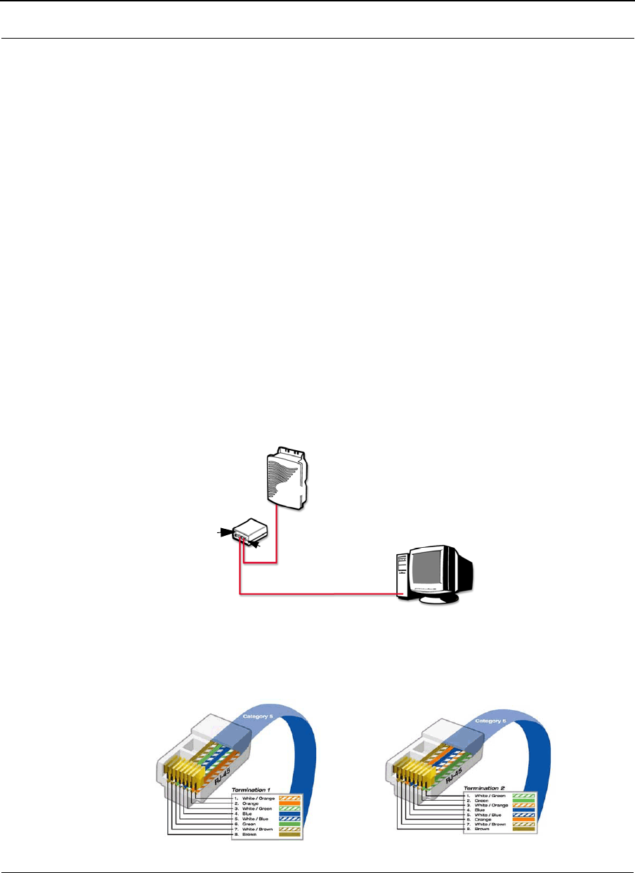
SPEEDLAN 9200 User Guide Part # 34357-MNL Rev. B
3-3
•a TCP/IP connection to the SPEEDLAN 9200.
A TCP/IP connection to the SPEEDLAN 9200 can be made through its wireless interface
or through its wired interface. If the default configuration creates a wireless LAN that is
compatible with the target inter-network, the network administrator can connect to the
individual SPEEDLAN 9200 router through that wireless LAN.
The following section assumes that a SPEEDLAN 9200 router is being configured via its
wired interface, possibly before it is installed at its intended physical location.
Connecting a SPEEDLAN 9200 and a Client PC
A connection between a SPEEDLAN 9200 and a client PC may be
established using either:
1one crossover cable, or
2two straight-through cables (also called patch cables) and a hub or a switch.
•If you select option # 1, connect one end of the crossover cable to the client PC
and the other end to the junction box.
Figure 3-1: Using one crossover RJ-45 Ethernet cable
Router
Junction box
Client PC
To rad io
To LAN
Either end of the
crossover cable can
connect to the client
PC or
junction box.
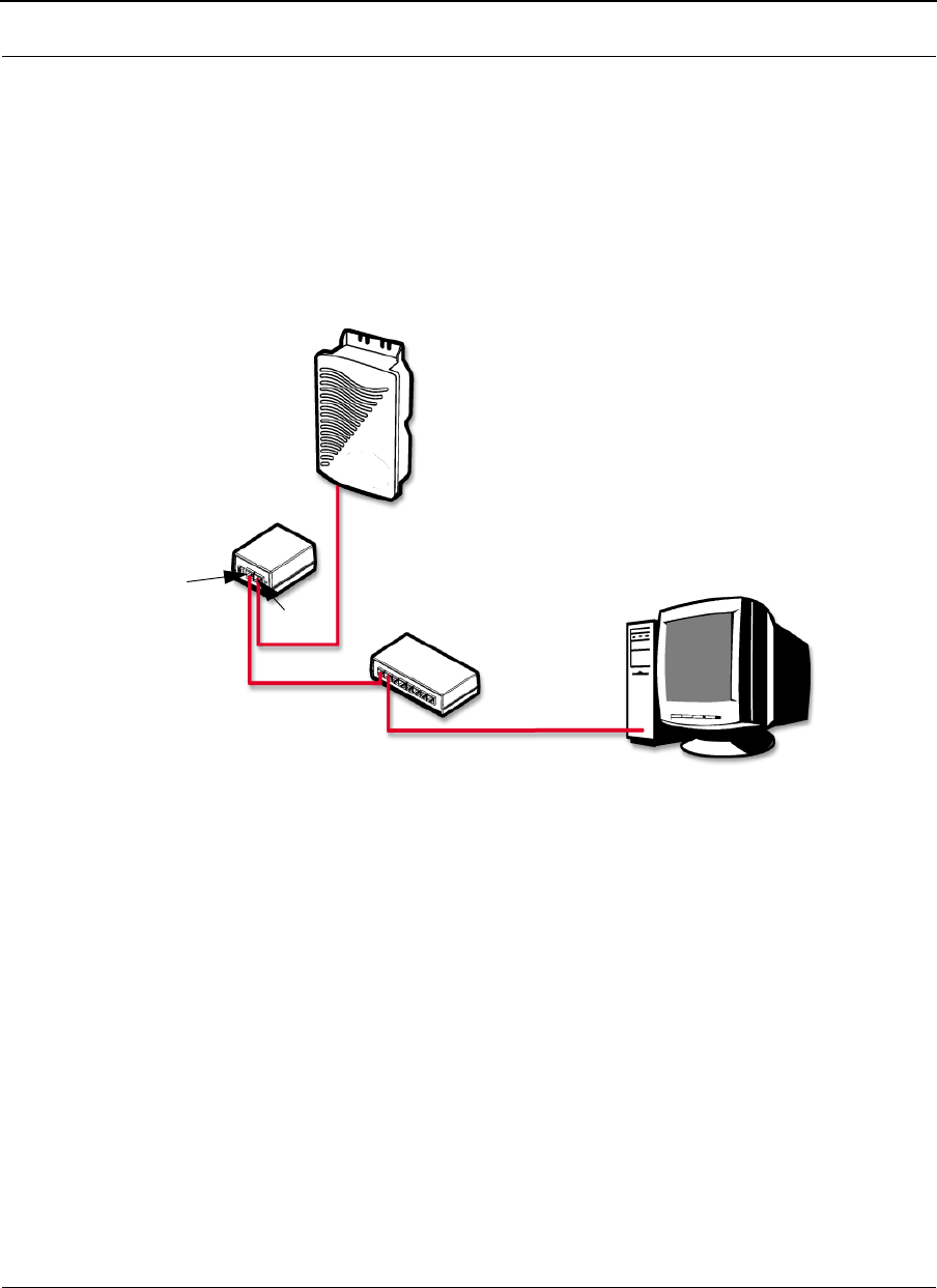
Part # 34357-MNL Rev. B SPEEDLAN 9200 User Guide
3-4
Figure 3-2: Crossover cable and pin out diagram
Note: The crossover cable actually crosses the transmit and receive pairs of wires so that
direct communications can take place between devices. Use a crossover cable anytime
you need to interconnect two computers or two devices in the same location when a hub or
a switch is either unavailable or not practical.
•If you select option # 2, connect a straight-through cable from both the client PC
and the junction box to the hub or a switch.
Figure 3-3: Using two straight-through RJ-45 Ethernet cables
SpeedLan 9200 comes from the factory pre-configuredwith a private IP network address
192.168.69.1 and a ?24 netmask (255.255.255.0)
Follow these general directions to configure your Speedlan connection:
•Open the Control Panel, and then double-click the Network and Dial-up Connec-
tions icon. Go to TCP/IP Protocol Properties to verify that your PC is on the same
network as the router 192.168.69.x (x is in the range of 2 - 254), and the subnet
mask should be /24 (255.255.255.0). If you made changes, accept the changes
and close this dialog box. Then, restart your computer.
Before continuing you should verify that the client PC has TCP/IP connectivity with the
SPEEDLAN 9200. The most common way to do this is to run 'ping' 192.168.69.1
To radio
To LAN
Client PC
Hub
Router

SPEEDLAN 9200 User Guide Part # 34357-MNL Rev. B
3-5
(or the DHCP assigned address) at a command-line prompt. This ping command is
available in a Windows 9x DOS prompt, a Windows 2000 / NT / XP command prompt, or
any Unix console.
Configuring the SPEEDLAN 9200
Once your PC can access the SPEEDLAN 9200, you can open the client's browser and
enter the IP address of the SPEEDLAN 9200 router.
Note: SPEEDView gives you a "monitoring" view of the network. You will use the
SPEEDLAN 9200 Configurator (web browser) to configure the SPEEDLAN 9200 routers.
If you want to configure a router in SPEEDView, just double-click any router and it will
open the SPEEDLAN 9200 Configurator. For more information about SPEEDView, see
the SPEEDManage User Guide.
Wireless Interface IP Address Assignment
If the wireless interface does not already have a statically configured IP address, it will
assume the 10.x.y.z/8 address, where x, y, and z are the decimal representations of the
least significant three octets of the IEEE 802 MAC address of the SPEEDLAN 9200’s
wireless interface. This method is used to ensure uniqueness. Because the last three octets
of the IP address are variable, a /8 netmask (255.0.0.0) is used in order for the
SPEEDLAN 9200s to communicate on this network.
Automating the Configuration of Multiple SPEEDLAN 9200s
Some of the configuration parameters for the SPEEDLAN 9200 are common to all
SPEEDLAN 9200s in the same network, for instance the channel and signaling rate of the
wireless interface.
Completing Configuration
Certain configuration parameters require a reboot after they have been changed.
Therefore, to ensure all changes have been activated, each SPEEDLAN 9200 should be
rebooted when its configuration is complete. Multiple SPEEDLAN 9200 routers can be
rebooted at the same time from either the SPEEDView application or the SPEEDLAN

Part # 34357-MNL Rev. B SPEEDLAN 9200 User Guide
3-6
9200 Configurator. To reboot the router in the SPEEDLAN 9200 Configurator, choose
Reboot from the System menu (see Reboot, page 3-30).
Adding Additional SPEEDLAN 9200s to the Wired Network
If you need to add an additional SPEEDLAN 9200 to the wired network, do the following:
•Connect the additional SPEEDLAN 9200 routers to a hub or switch on the
network and have DHCP assign IP addresses dynamically.
•Connect additional SPEEDLAN 9200 routers to a hub or switch on the network
one at a time, changing the wired IP address of each router as it is added, to an
address other than 192.168.69.1 (to avoid duplicate IP addresses).
If you need help, contact your system administrator.
Overview of the SPEEDLAN 9200 Configurator General Main
Menu
How the Configurator Menu is Structured
Base stations, CPE routers, point-to-point routers and mesh routers all use the same main
menu, as shown in Figure 3-4 on page 3-9. However, some of the submenus are limited
depending on which mode you are operating, such as base station mode, CPE mode,
point-to-point (primary and secondary), and mesh mode. Any configuration that is
common for the base station, CPE, point-to-point, and mesh router is
located in this chapter.
Network menu
Use this menu to view a list of the interfaces that exist on the router, such as wireless
interfaces, fixed interfaces, or both. This is where you would assign either a static or
dynamic Internet address for the router. You will also be able to define the display name
for the wireless or fixed device and add an Alias IP. For more information, see IP Address
Configuration, page 3-18.
•If you need to view mesh routers currently on the network, Mesh Nodes,
page 4-3. To authenticate your mesh routers and enable security for
SPEEDMesh-enabled clients, see Enabling Network Security, page 4-4. To

SPEEDLAN 9200 User Guide Part # 34357-MNL Rev. B
3-7
enable AES encryption in your network, see A. Enabling Encryption
Between SPEEDLAN 9200 Routers, page 4-4. To enable WEP security on a
SPEEDMesh-enabled client, see B. Enabling WEP Security Between a
SPEEDMesh-Enabled Client and SPEEDLAN 9200, page 4-5. To allow a
mesh node in a 9200 network to communicate with a SPEEDMesh-enabled
client, see Enabling/Disabling the SPEEDMesh-Enabled Client, page 4-6.
System menu
Use this menu to define information about the host, view information about the
SPEEDLAN 9200 Configurator, set the current password and reboot the SPEEDLAN
9200 router. For more information see, System Menu, page 3-24. To view a configuration
summary of the units on the network, see Configuration Summary, page 3-24. The
SPEEDLAN 9200 contains a Simple Network Management Protocol (SNMP) Agent that
provides a remote Network Management System (NMS) with read-only ("get") access to
certain configuration and status parameters. For more information, see SNMP,
page 3-25.
Routing menu
Use this menu to view and set routing configuration. For more information, see Routing
Menu, page 3-36. This is also where you can set RIP-2 MD5
Authentication (see Authentication on RIP-2 MD5, page 3-39).
Wireless menu
Use this menu to configure the wireless parameters.
•If you choose Configuration, you will be able to set the following radio
parameters: SSID, wireless mode, channel, signaling rate, turbo mode, Tx
power and preamble. For more information, see Configuration, page 3-43
for more details.
•If you choose Tx Retries, you will be able to set the Transmit Retry Limit and
Signaling Rate Fallback. For more information, see Max Tx Retries and Sig-
naling Rate Fallback, page 3-46.
•If you choose Max Throughput, you will be able to set the Max Transmit
Data Rate in Kb/s. For more information, see Max Throughput (Regulating
Bandwidth), page 3-48.
Other specialized parameters not common under the Wireless menu for mesh routers:

Part # 34357-MNL Rev. B SPEEDLAN 9200 User Guide
3-8
•RTS/CTS has been added to this chapter. See Request to Send (RTS) / Clear
to Send (CTS), page 4-8. RTS/CTS allows you to fine-tune the
operation of your wireless LAN. It will help minimize collisions between
transmissions from hidden nodes on the wireless network.
•If you choose Rx Threshold, you will be able to set the threshold for each
mesh router on the network. For more information, see Receive (Rx) Thresh-
old Parameter, page 4-9 for details.
•If you choose Blocked Links, you will be able to block or unblock mesh rout-
ers. For more information, see Blocked Links, page 4-10 for more details.
•If you want to enter the number of times that a neighbor node can fail to
reply to a neighbor discovery probe before it is declared unreachable, see
Link Expiration, page 4-11.
•DHCP
Use this menu to configure a DHCP server on one or more of the wired
interfaces. You can also view log messages and view the interfaces being
serviced with DHCP. For more information see, DHCP Server Menu, page 3-56.
You can also enable DHCP Relay and set the parameters as needed.
•Forwarding
Use this menu to control how traffic is forwarded through this router. For more
information, see Forwarding Menu, page 3-63.
•Diagnostics
Use this menu to troubleshoot your SPEEDLAN 9200 network. For more
information, see Diagnostics Menu (Troubleshooting the Network), page 3-79.
•Admin
Use this menu to perform administrative tasks, such as setting up user
password and permission information. You can also remotely control the
SPEEDLAN 9200 routers on the network, update software, reset all
configuration to the factory default, enable or disable SPEEDSignal, and enable
manufacturer access to the router for advanced troubleshooting. For more
information, see Admin Menu, page 3-85.
•If you need to remotely reboot or turn off the SPEEDLAN 9200 mesh
routers, see Remote Control, page 4-12.
•If you need to remotely reboot a mesh router, see Remote Control,
page 4-12. If you need to update the software on the mesh routers, see Soft-
ware Update, page 4-12.
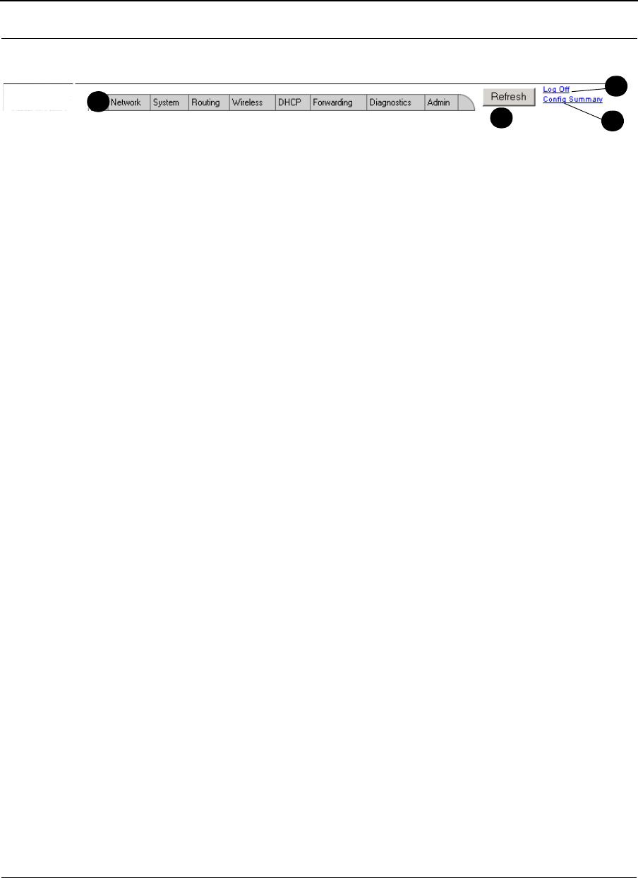
SPEEDLAN 9200 User Guide Part # 34357-MNL Rev. B
3-9
Diagram of SPEEDLAN 9200 Configurator Main Menu
Figure 3-4: Main menu
a Main menu: Contains the following menus: Network, System, Routing, Wireless,
DHCP, Forwarding, Diagnostics and Admin.
bRefresh button: Click to Refresh data on the web page.
cLog Off link: Click to close a user session.
dConfig Summary link: Click to view a summarized list of the configuration on the
routers (units). For more information, see Configuration Summary, page 3-24
Note: If you want to learn more about IP addressing, see Basics of IP Addressing,
page 5-2.
Logging on the SPEEDLAN 9200 Configurator
To access the SPEEDLAN 9200 Configurator, open your web browser and enter the URL
(https://) or IP address of the router you want to configure. The factory default IP address
is 192.168.69.1.
Note: The SPEEDLAN 9200 Configurator can be accessed at the standard web (HTTP,
port 80) and secure web (HTTPS, port 443) locations. If you have forwarded either of
those ports to internal network nodes, you can still reach the configurator at an alternate
location:
•port 6590 - server alternate HTTPS (for example, type "https://
192.168.69.1:6590/")
Classes of Users (and Passwords)
All software including the SPEEDLAN 9200 Configurator and SPEEDManage share the
same password(s). The only place where you change the password for all of these is in the
d
ab
c
d

Part # 34357-MNL Rev. B SPEEDLAN 9200 User Guide
3-10
SPEEDLAN 9200 Configurator. For more information about SPEEDManage, see the
SPEEDManage User Guide.
There are five classes of users on the SPEEDLAN 9200. The classes are as follows with
their default passwords:
•Full Access (also known as a superuser): "wave_full" (this is also the only access
password for IP Recover in the SPEEDManage suite). Use this option when
changing passwords. You cannot change the password to an existing password.
Note: "Full Access" does not show up in "Admin/Users" because the user will not
be able to change its permissions and it has write permission on
everything.
•Wired Admin: "wave_wired_admin" (account for the private Ethernet network)
•Wired Read: "wave_wired" (account for the private Ethernet network)
•Wireless Admin: "wave_wireless_ad" (account for the wireless SPEEDLAN
9200 network)
•Wireless Read: "wave_wireless" (account for the wireless SPEEDLAN 9200
network)
Notes:
The minimum password length is 8 characters. The maximum password length is 16
characters (including the underscore character or spacebar). Any characters over the
maximum length (16) will be truncated. This rule applies for the Configurator and the
SPEEDManage suite.
Admin accounts have administration rights to their appropriate network (wired or
wireless), and Read Only accounts have only read only access.
If you are a network administrator and want to modify the default passwords and settings
for any of the users, choose the Admin menu. For more information, see Admin Menu,
page 3-85.
Logging On
Follow these steps (starting on the following page) to log on to the SPEEDLAN 9200
Configurator.
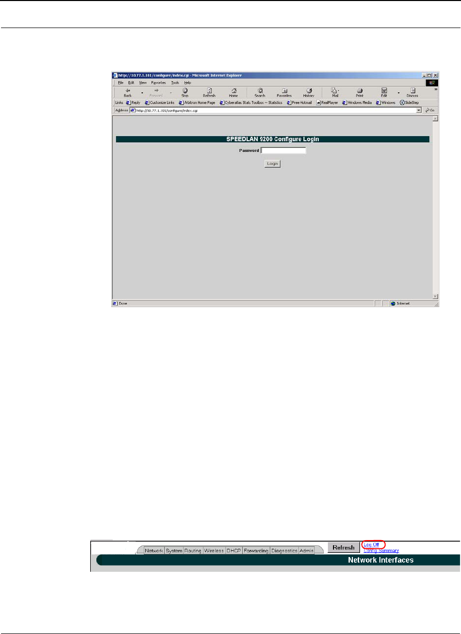
SPEEDLAN 9200 User Guide Part # 34357-MNL Rev. B
3-11
1Make sure you entered the correct URL or IP address of the router. For more
information, see Logging on the SPEEDLAN 9200 Configurator, page 3-10.
Figure 3-5: Login page
2Enter the password in the Password text box. To know which password (from 8 to
16 characters) you should enter, see Classes of Users (and Passwords),
page 3-10.
3Login by clicking Login.
4When you login for the first time, the Security Alert dialog box will appear.
Follow the directions under Understanding the Security Alert Screens,
page 3-12.
Logging Off
If you need to log off the Configurator, click the Log Off link (as circled in red in the
figure below).
Figure 3-6: Logging Off
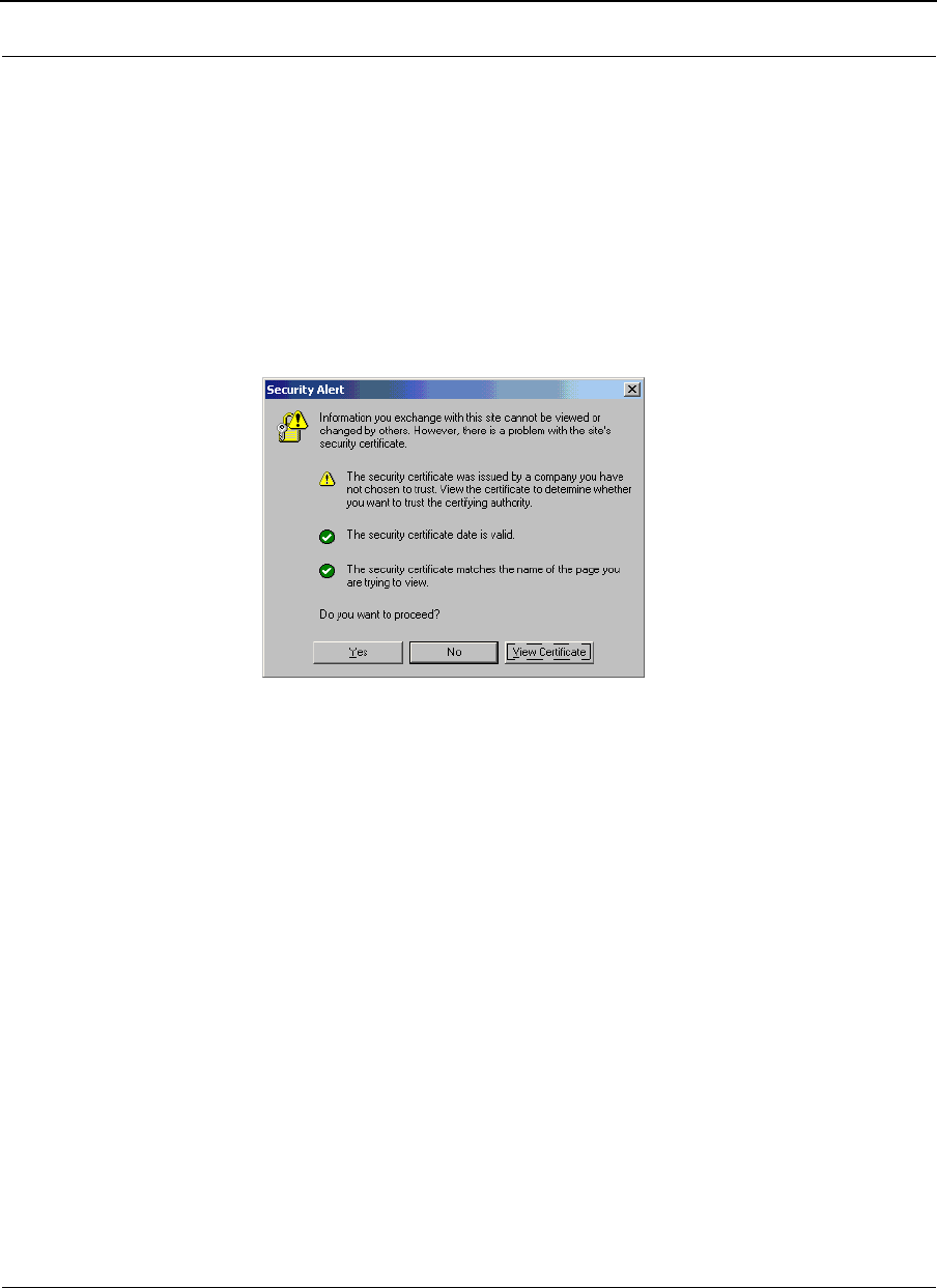
Part # 34357-MNL Rev. B SPEEDLAN 9200 User Guide
3-12
Understanding the Security Alert Screens
In order to avoid a security alert each time the SPEEDLAN 9200 Configurator is
accessed, you must install its security certificate into Internet Explorer. If the SPEEDLAN
9200's host name changes, you will have to repeat this process.
Follow the steps beginning on the next page:
1When the Security Alert dialog box appears, click View Certificate (right most
button on bottom of Security dialog box). The following dialog box will appear.
Figure 3-7: Security Alert screen
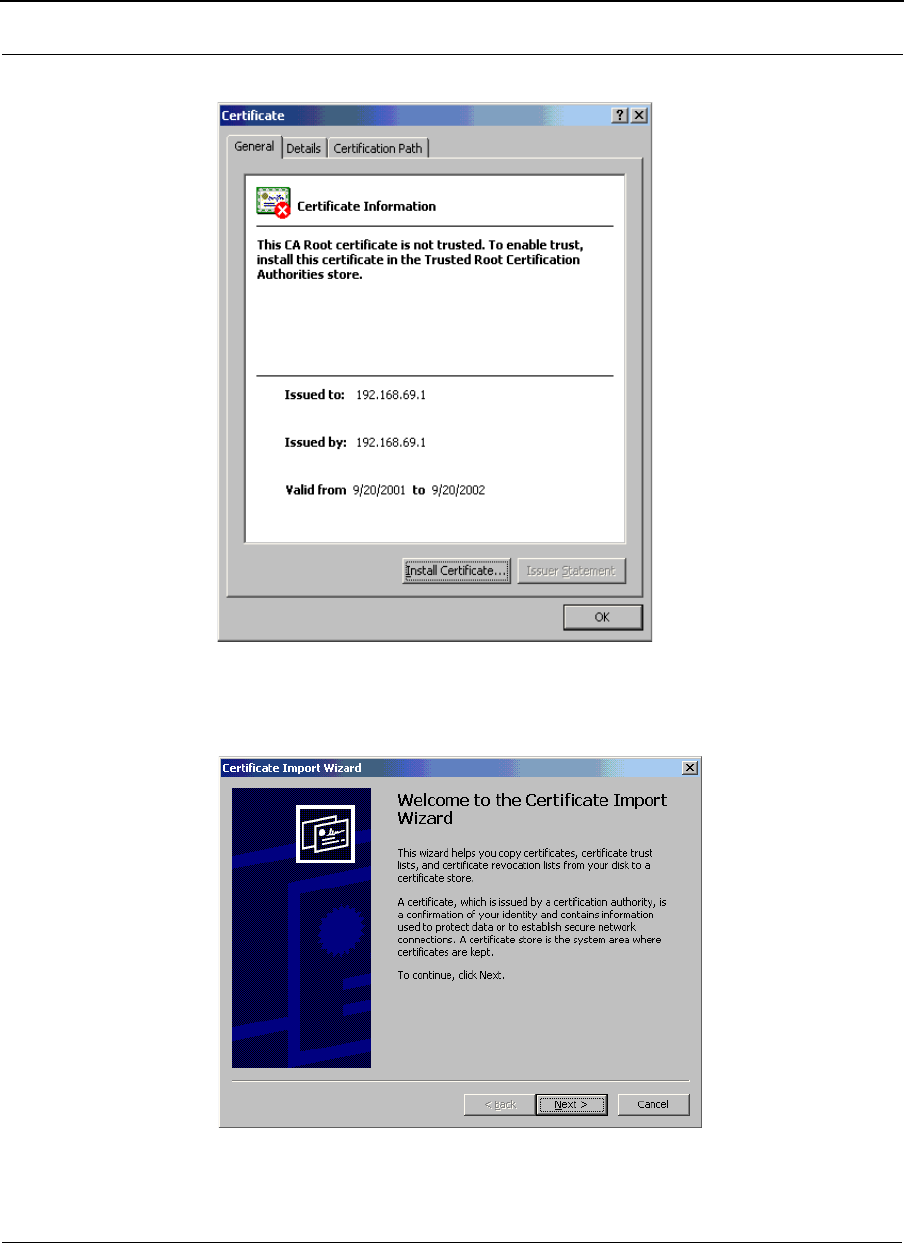
SPEEDLAN 9200 User Guide Part # 34357-MNL Rev. B
3-13
2Click Install Certificate.
Figure 3-8: Certificate screen
3The Certificate Import Wizard will appear.
Figure 3-9: Certificate Import Wizard screen 1
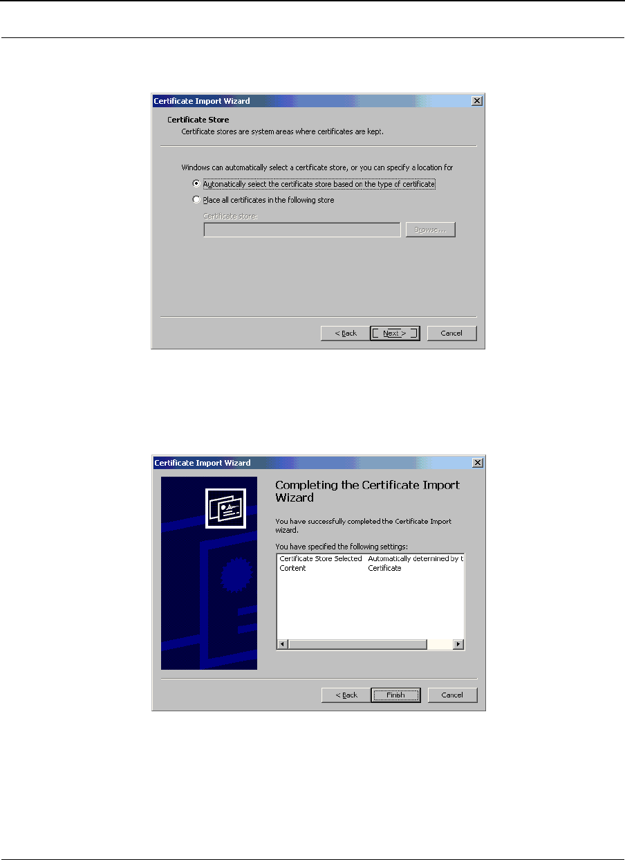
Part # 34357-MNL Rev. B SPEEDLAN 9200 User Guide
3-14
4 Click Next.
5The following dialog box will appear.
Figure 3-10: Certificate Import Wizard screen 2
6Click Next again.
7The following dialog box will appear.
Figure 3-11: Certificate Import Wizard screen 3
8Click Finish. A message will appear asking you "if you want to add a certificate
to the Root Store." Click Yes.
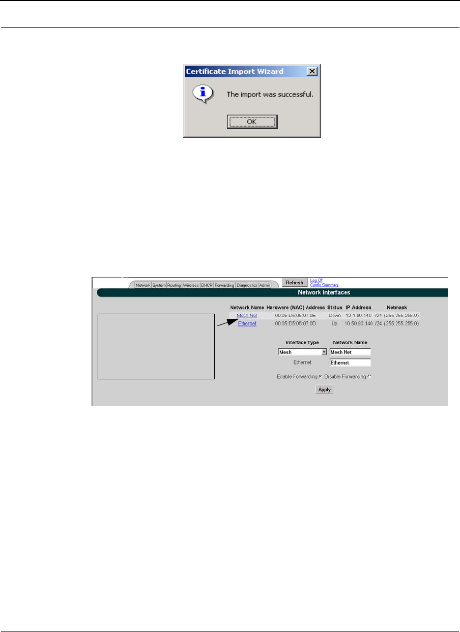
SPEEDLAN 9200 User Guide Part # 34357-MNL Rev. B
3-15
9You will see a confirmation stating that the import was successful. Click OK.
Click OK again. If the Security Alert dialog box appears, click Yes.
Figure 3-12: Certificate Import Wizard message box
You should not get the Security Alert the next time you access this site. The SPEEDLAN
9200 Configurator web site will appear.
After Logging On
After you log on, you will see the Network Interfaces page, as displayed below.
Figure 3-13: 1st screen after logging on
Elements to know on the Network Interfaces page:
•If you click the interface link, Ethernet, you will jump to the IP Addresses page.
•The "Interface Type" drop-down list is where you select the type of router. To
select a different mode, select it and click Apply. The Configurator will log you
out, reboot the unit, and the next time you log in the mode will be available.
•Click the Refresh button to refresh data.
•The name you enter in the Network Name text box (shown in Figure 3-13 on
page 3-15) determines what the interfaces are called on the network. For
instance, you can enter, "Star Net" in the Network Name text box to represent the
This is where the user
can obtain the MAC address,
status, IP address,Net Mask
for the MeshNet/Ethernet
section of the Router

Part # 34357-MNL Rev. B SPEEDLAN 9200 User Guide
3-16
"Star CPE" interface. This option just gives the user control over the name of the
interface.
What are enable and disable forwarding?
•Enable Forwarding: Select the Enable Forwarding option to enable the
forwarding of IP packets from the wired interface to the wireless interface and
vice-versa.
•Disable Forwarding: Select the Disable Forwarding option to disable the for-
warding of IP packets from the wired interface to the wireless interface and vice-
versa.
Helpful Information to Know...
How do you select the router?
As shown in Figure 3-13 on page 3-15, select the type of router (e.g., mesh) from the
Interface Type drop-down list. Then, click Apply. The SPEEDLAN 9200 Configurator will
then recognize the router you selected and allow you to make modifications as needed.
Note: If you need to change the router's topology mode (base station, CPE, point-to-point
or mesh) from or to another topology mode (base station, CPE, point-to-point or mesh),
see Changing the Router's Topology Mode, Change Topology Mode, Appendix A-2.
(Directions are also described in the previous figure, see Figure 3-13 on page 3-15.)
References on Setting Up the Router
The next step is to set up your router. Follow this chapter to set up the IP address, set
routing information, set DHCP, set NAT information, troubleshoot network errors
(diagnostic information), and enter basic Administrative information. Make sure you see
the section called, Overview of the SPEEDLAN 9200 Configurator General Main Menu,
page 3-6. This section will tell you which functions are common to all routers and which
functions are specialized. This will help you locate the proper section in the manual more
quickly.
Caching - viewing the most recent version of a page
Important Note: If you do not see the changes you made on a configurator page, click the
Refresh button, as shown in Figure 3-13 on page 3-15. Then, the changes will appear.

SPEEDLAN 9200 User Guide Part # 34357-MNL Rev. B
3-17
If the above procedure does not work, follow these steps below:
1Go to your Internet browser. (These directions are for Internet Explorer.)
2From the Tools menu, choose Internet Options. The Internet Options dialog box
appears. Click the Delete Files button. Then, click OK.
3On the Internet Options dialog box, click the Settings button. The Settings dialog
box appears. Select the Every visit to the page option. This makes sure that the
new information is displayed the next time you visit the
configurator web page, and the new information will also be added on the
SPEEDLAN router.
Session Activity
If you receive this message during your configuration session, "Sorry, the maximum
number of sessions has been reached. Try to login later," this is because the maximum log
on is 32 concurrent sessions.
If you receive this message during your configuration session, "Your session has expired
due to inactivity or because another user has made configuration changes that affect your
session, " this is because the configuration session’s default time is 30 minutes.
SPEEDLAN 9200 Firmware Updates, SPEEDManage or Other
Utility Programs
Registered customers should check our web site on a regular basis for updates to router
firmware, SPEEDManage, and other utility programs. If you haven't registered your
products yet, you may do so by visiting www.p-com.com + click on the Wave Wireless
Logo + Support. For more information about SPEEDManage, see the SPEEDManage
User Guide.
If You Need a Temporary IP Address
•If after learning the IP address of the Ethernet interface, you cannot log on to the
router using the HTML Configurator (SPEEDLAN 9200 Configurator), then you
will be able set a temporary Ethernet IP address so that a connection can
made.The temporary IP address will last until next reboot or interface start.

Part # 34357-MNL Rev. B SPEEDLAN 9200 User Guide
3-18
OR
•For additional information, see the IP Recover chapter in the SPEEDManage
User Guide.
The Configuration Menu
Network Menu
•Choose Interfaces to select the router you need.
•Choose IP Addresses from the Network menu to assign an IP address
(manually or dynamically via DHCP).
•Choose Virtual Addresses from the IP Addresses submenu (under the
Network menu) to create a public IP address that can be mapped to a private IP
address.
Network Interfaces
Choose the type of router as shown in Figure 3-13 on page 3-15. Then, click Apply.
IP Address Configuration
This is where you would assign IP Addresses either Manually (static) or via DHCP
(dynamic). For DHCP, you may also enter the hostname of the client.
To activate this page, choose IP Addresses and then the name of the interface (i.e.,
Ethernet, Star Net, Mesh Net) from the Network menu. The following page will appear.
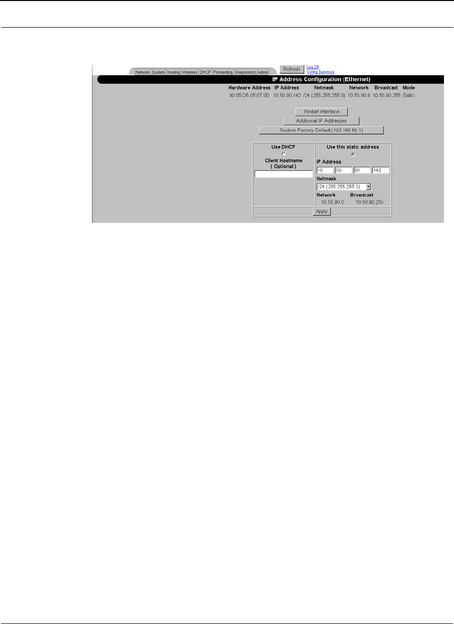
SPEEDLAN 9200 User Guide Part # 34357-MNL Rev. B
3-19
The following page similar to the following will appear. (This is showing a Mesh
interface.)
Figure 3-14: IP Addresses page
After you choose the appropriate interface, you will be able to view the following
parameters:
•Hardware (MAC) Address: In a LAN environment each network interface con-
tains its own Medium Access Control (MAC) address which is the
embedded and unique hardware number.
•IP Address: This address tells the network how to locate the computers or
network equipment connected to it.
•Netmask: The netmask is a 4-byte number that masks the network part of the
Internet Protocol IP address, so only the host computer part of the address
remains.
•Mode: "Static" or "DHCP."

Part # 34357-MNL Rev. B SPEEDLAN 9200 User Guide
3-20
CIDR Table (For Netmask Information Purposes)
Figure 3-15: CIDR information page
•Restart Interface: Click to restart the interface.
•Additional IP Addresses: Click this button to add an Alias IP. (You can add an
alias IP address to the Ethernet interface.) This allows you to assign more than
one IP address to an Ethernet interface. For more information, see Alias IP,
page 3-21.
•Restore Factory Default: Click to revert to factory default settings for this inter-
face.
•Use DHCP: Select this option if you want to dynamically acquire an IP address
or DHCP from a DHCP server. The DHCP (Dynamic Host Configuration
CIDR Length Mask # Networks
# Hosts
/8 255.0.0.0 1 A 16,777,214
/9 255.128.0.0 128 B 8,388,352
/10 255.192.0.0 64 B 4,194,176
/11 255.224.0.0 32 B 2,097,088
/12 255.240.0.0 16 B 1,048,544
/13 255.248.0.0 8 B 524,272
/14 255.252.0.0 4 B 262,136
/15 255.254.0.0 2 B 131,068
/16 255.255.0.0 1 B 65,534
/17 255.255.128.0 128 C 32,512
/18 255.255.192.0 64 C 16,256
/19 255.255.224.0 32 C 8,128
/20 255.255.240.0 16 C 4,064
/21 255.255.248.0 8 C 2,032
/22 255.255.252.0 4 C 1,016
/23 255.255.254.0 2 C 508
/24 255.255.255.0 1 C 254
/25 255.255.255.128 2 Subnets 124
/26 255.255.255.192 4 Subnets 62
/27 255.255.255.224 8 Subnets 30
/28 255.255.255.240 16 Subnets 14
/29 255.255.255.248 32 Subnets 6
/30 255.255.255.252 64 Subnets 2
/31 255.255.255.254 none none
/32 255.255.255.255 1/256 C 1

SPEEDLAN 9200 User Guide Part # 34357-MNL Rev. B
3-21
Protocol) server assigns the IP address to each computer as the computer
connects to the network. If a computer moves to a new network, it must be
assigned a new IP address for that network. DHCP can be used to manage these
assignments automatically. Then, click Apply.
Optional: If you prefer, you can enter the client name of the host in the Client
Hostname text box (under "Use DHCP"). The limit of the Client Hostname is 16
characters. (See also Important Note about DHCP, page 3-57.)
•Use this static address: Select this option if you want to statically assign an IP
address to the interface. For example: you may want to assign a "static" (perma-
nent) address to a computer that will always be used as a server. This enables
other computers to connect to it. Static addressing is also beneficial to users that
need to maintain a "constant" connection to the Internet. Then, click Apply.
Note: If you selected the "Use this static address" option, enter the Internet address that
you want to assign to the interface in the IP Address text box. You will also enter the
subnet/netmask for the IP address. Select the appropriate netmask in the Netmask drop-
down list.
After you change the Internet address for an Ethernet or directly connected interface, you
must restart the interface. Otherwise, the information will not be activated. If you follow
this step correctly, the next time you open the SPEEDLAN 9200 Configurator, these
changes will be updated.
Alias IP
Note: Alias IP addresses can only be created for the Ethernet interface. They are not for
the wireless interface.
To add an Alias IP, do the following:
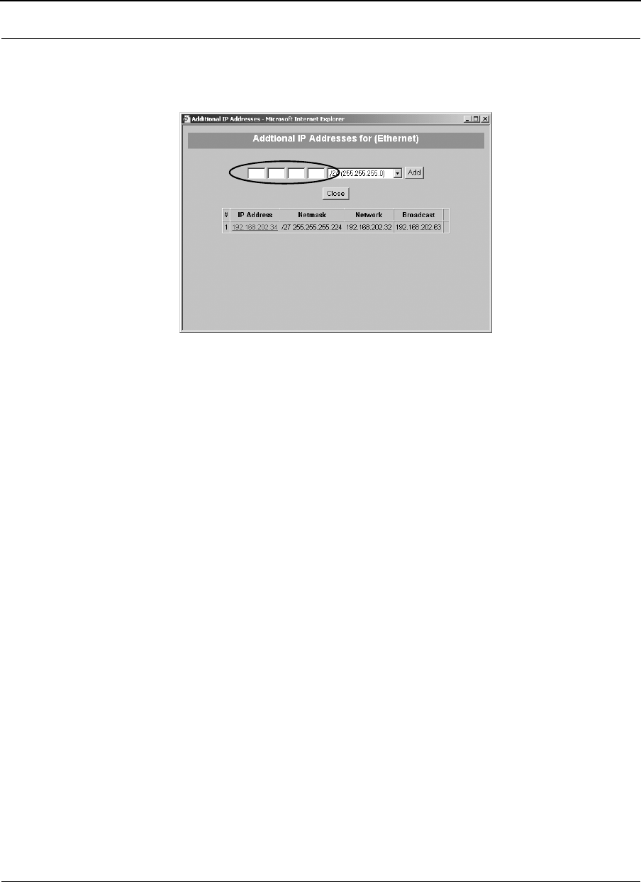
Part # 34357-MNL Rev. B SPEEDLAN 9200 User Guide
3-22
1Choose IP Addresses + Ethernet from the Network menu. Next, click the Addi-
tional IP Addresses button on the IP Address Configuration (Ethernet) page. The
IP Addresses Configuration (for Ethernet) page will appear:
Figure 3-16: Adding an Additional IP Address (Alias IP)
2Aliased addresses cannot be dynamically assigned from the DHCP server, so you
must manually type in the Alias IP in the text box, circled above. Verify the
netmask and click Add. Repeat this step for each Alias IP you add to the Ethernet
interface.
Other elements on this window are described below:
•# - (Address Number): The first address is the primary IP address on the
Ethernet interface. Addresses numbered 2 or higher are aliases.
•IP Address: Lists the IP address of the primary or alias address.
•Netmask: Lists the netmask of the primary or aliased address.
•Network: Lists the network number of the primary or aliased address.
•Broadcast: Lists the broadcast address of the primary or aliased address.
Virtual Addresses
Choose Virtual Addresses from the IP Addresses submenu (under the Network menu) to
create a public IP address that can be mapped to a private IP address. Virtual addresses
are IP addresses (usually public) that the SPEEDLAN 9200 router can use in addition to
the IP addresses assigned to each of its network interfaces. Virtual addresses are
normally used to preserve public IP addresses when a limited number is available.
Previously, virtual addresses were implicitly created when referenced in a NAT rule.

SPEEDLAN 9200 User Guide Part # 34357-MNL Rev. B
3-23
Virtual addresses can be used to access the SPEEDLAN 9200 router for configuration, or
in NAT functions like Address Sharing, Internal Servers, and 1:1 NAT. Virtual addresses
are particularly useful when using 1:1 NAT, where you need more than one public IP
address. The virtual addresses do not need to belong to a network assigned to one of the
SPEEDLAN 9200's interfaces.
The existence of these addresses will be advertised with RIP, providing that the RIP filters
allow it. The Virtual Address page will appear when you choose the Virtual Addresses
feature.
The elements on this page are explained below:
•IP Address: In this text box, enter the virtual address you want to add. Click Add
to add the new virtual address. (In the next figure, the user entered "13.13.13.16"
in the IP Address text box. Next, the user will click Add.)
Notes: You cannot apply an IP address from the Ethernet port’s subnet.
All virtual addresses have a netmask of /32 (255.255.255.255).
Existing Virtual Addresses
This list contains all defined virtual addresses.
•To remove a virtual address, select it and click Delete Selected. (In the next fig-
ure, if the user wants to remove virtual address "13.13.13.14". Then, the user
would select the check box next to it and click Delete Selected.)
•To select all addresses, click All. To clear all selections, click None.
If an entry has "(In Use)" instead of a check box (as shown in the next figure to the right of
virtual address "13.13.13.13"), this means the virtual address is "in use" and cannot be
removed.
Figure 3-17: Virtual address

Part # 34357-MNL Rev. B SPEEDLAN 9200 User Guide
3-24
Note: If you want to distribute virtual routes, make sure the Static Routes check box is
selected on the RIP Global Settings page under the Routing / RIP2 Setup / Global Settings
menu.
System Menu
•Choose Config Summary to view a summarized configuration of the units.
•SNMP: The SPEEDLAN 9200 contains a Simple Network Management
Protocol (SNMP) Agent that provides a remote Network Management System
(NMS) with read-only ("get") access to certain configuration and status
parameters. For more information, choose SNMP.
•Choose Version to view the current version information.
•Choose Host Name to enter a name of the host.
•Choose Password to modify the password entries.
•Choose Reboot to reboot the system.
Configuration Summary
To view a summarized list of the configuration on the units, choose Config Summary from
the System menu. (You can also select the Config Summary link in the upper-right hand
corner of each page.) This is very useful tool if you want to capture a screen shot of the
summary and email it to technical support. The Configuration Summary for the Host page
will appear displaying a summary which includes the following information:
•System Version: Displays the firmware version and uptime for the unit.
•SNMP: Displays the read-only SNMP configuration parameters and their cur-
rent status which are described in SNMP, page 3-25.
•Network Interfaces: Displays the interfaces on the network.
•Route Table: Displays the routing information between destinations.
•Wireless Configuration: Displays the channel, signaling rates, Max Tx Retries,
Signaling Rate Fallback, SSID, Max Throughput, Rx Threshold and
Link Expiration.
• Blocked Wireless Links: Displays blocked links. For more information, see
Receive (Rx) Threshold Parameter, page 4-9.
•Wireless Security Settings: See Enabling Network Security, Chapter 8.
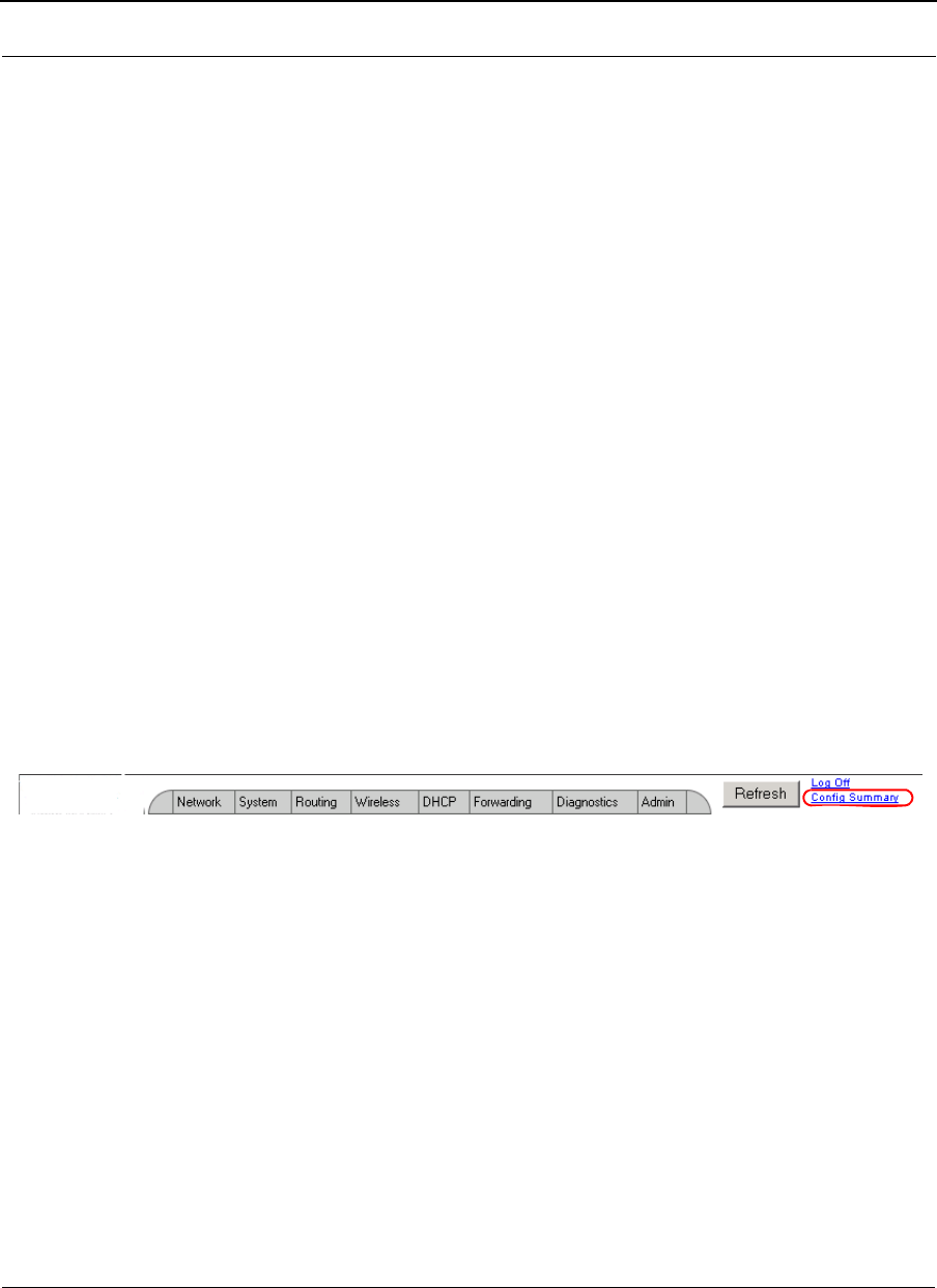
SPEEDLAN 9200 User Guide Part # 34357-MNL Rev. B
3-25
•RIP Configuration: The routing table displays routing information between desti-
nations.
•Routing Configuration: Indicates if RIP is on or off, lists global settings and send
and receive information, authentication and distribute information.
•DHCP Server Configuration: Indicates if DHCP Server Configuration is on or
off.
•DHCP Relay Configuration: Indicates if DHCP Relay Configuration is on or off.
•Virtual Addresses: Displays virtual addresses.
•NAT: Lists the implementation(s) of NAT: address sharing, internal servers and
1:1 NAT.
•Firewall: Displays if the firewall is enabled or disabled.
•ARP Table: Displays Address Resolution Protocol statistics.
•Statistics: Displays statistics about the wireless inbound and outbound traffic.
Note: Select the appropriate feature (noted via blue-underlined hyperlink) to jump to the
proper feature page. For example, if you click the Firewall link on the Configuration
Summary page, it will bring up the Firewall page where you can modify further
information.
There is a short-cut link to the Configuration Summary by clicking the Config Summary
Link as circled in the figure below.
Figure 3-18: Config Summary Link
SNMP
The SPEEDLAN 9200 contains a Simple Network Management Protocol (SNMP) Agent
that provides a remote Network Management System (NMS) with read-only ("get") access
to certain configuration and status parameters. Those parameters are Management
Information Base (MIB) objects. The currently supported MIBs are identified in table the
MIBs.
The SPEEDLAN 9200 supports communications with an NMS using SNMP versions 1, 2
or 3. Secure communications between NMS and Agent requires use of SNMP version 3.
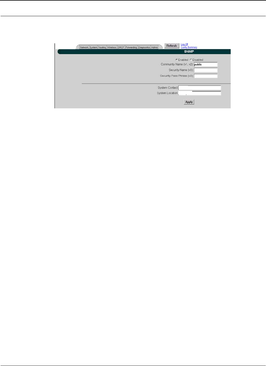
Part # 34357-MNL Rev. B SPEEDLAN 9200 User Guide
3-26
To enable the SNMP Agent, do the following:
1Choose SNMP from the System menu. The following page will appear:
Figure 3-19: SNMP
2Enter the following information, depending on the version(s) of the SNMP
protocol supported by your NMS, and the level of security required:
•Community Name (v1, v2): This is the read-only password. This entry is
blank by default - you have to create one for the service to work. (If this
entry is left blank, SNMP v1 or v2 service will be disabled.) The minimum
number of characters entered is 1 and the maximum number of
characters entered is 30. The default name is "public". If you want to use
SNMP v1 or v2, enter the community name. Otherwise, leave this entry
blank.
•Security Name (v3): This is the read-only 'user name' used for SNMP v3.
This entry should be set to a value that is only known by the network admin-
istrator. The minimum number of characters entered is 1 and the maximum
number of characters entered is 30.
•Security Pass Phrase: This is the 'password' for SNMP v3. The minimum
number of characters entered is 8 and the maximum number of
characters entered is 30.
Note: If you want to use SNMP v3, enter the Security Name and Security Pass Phrase.
Otherwise, leave these entries blank.
•System Contact: This field should contain the identification of the contact
person for this SNMP-managed node.
•System Location: This field should contain the administratively assigned
name for this managed node. By convention, this is the node's fully
qualified Internet Domain name (e.g., "noc.domain.com").
3After you have entered the information described above, click Apply.
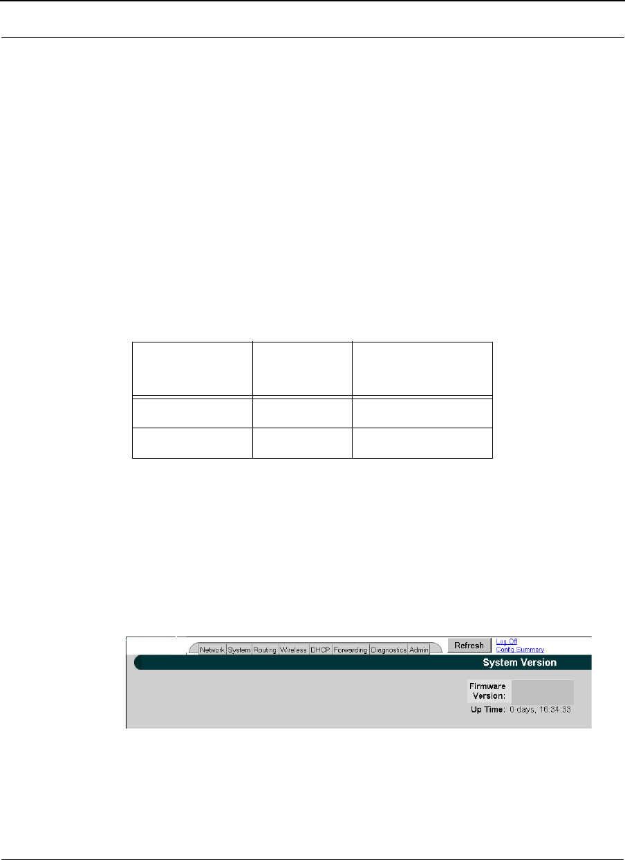
SPEEDLAN 9200 User Guide Part # 34357-MNL Rev. B
3-27
4Enable SNMP by selecting the Enabled option. When SNMP is enabled, the
SPEEDLAN 9200 router will respond to SNMP queries initiated by your NMS.
(See the section below for MIBII strings and definitions.) If you want to disable
it, click the Disabled option. (SNMP is disabled by default.)
5You will receive a confirmation that your settings have been applied. SNMP is
now enabled on the node you want to monitor.
6To view SNMP information, you must now use a NMS. Consult your NMS soft-
ware for information on polling and logging the MIB objects.
Table 3-1: List of MIBs supported by SPEEDLAN 9200
+RFC = Internet Engineering Task Force (IETF) Request for Comments
(http://www.rfc-editor.org/rfc.html)
Version
This page displays information about the current version. When you choose Version under
System menu, the System Version page appears displaying the following information.
Figure 3-20: Version page
•Firmware Version: The version of the firmware.
•Up Time: The time since the last system startup was initialized.
MIB Name RFC+SPEEDLAN 920x
Firmware
MIB-II RFC1213 1
SNMPv2-MIB RFC3418 1
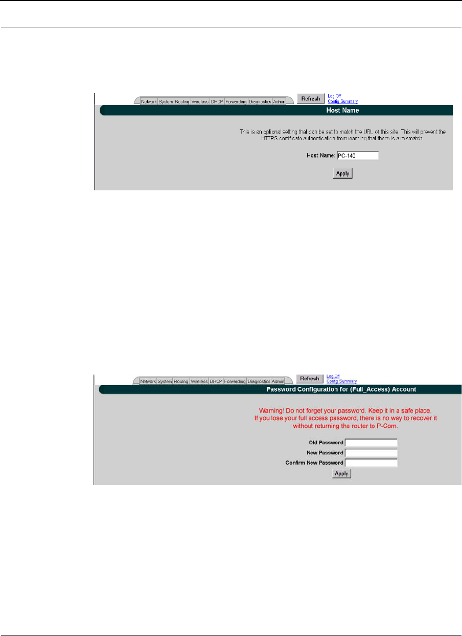
Part # 34357-MNL Rev. B SPEEDLAN 9200 User Guide
3-28
Host Name
To enter the host name of a SPEEDLAN 9200 router, choose Host Name from the System
menu. The following page will appear.
Figure 3-21: Host Name page
The hostname should contain the administratively assigned name for this managed host.
Password
This is where you modify the password for the current account on the SPEEDLAN 9200
Configurator. To modify password information, choose Password from the System menu.
The following page will appear.
Figure 3-22: Password page
To enter a new password, do the following:
1Enter the old Password in the Old Password text box.
2Next, enter the new password in New Password text box.
The minimum password length is 8 characters. The maximum password length is
16 characters (including the underscore character or spacebar).
Log Off
Config Summary

SPEEDLAN 9200 User Guide Part # 34357-MNL Rev. B
3-29
3Finally, confirm the new password in the Confirm New Password text box and
click Apply.
Reboot
To reboot the system, choose Reboot from the System menu. Then, click the Reboot
button. After clicking Reboot, it could take a minute for the SPEEDLAN 9200 to become
fully operational following a reboot.
SYSTEM MESSAGE LOGGING
Linux syslog feature is supported in SPEEDLan 9200 to log system messages. Messages
are forwarded to a central daemon by library functions.
To access System Logs configuration page, choose Message Log->Configure from System
main menu.
!
Warning! Do not forget your password. Keep it in a safe place.
If you lose your full access password, there is no way to recover
it without returning the router to the manufacturer.
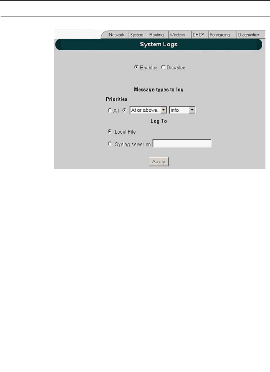
Part # 34357-MNL Rev. B SPEEDLAN 9200 User Guide
3-30
Figure 3-23: System Logs
System logs page provides the following settings to allow user to configure the logs on the
system:
•Enable/Disable - Choose enable or disable radio button to enable or disable system
messages logging respectively;
•Choose message priority level to be logged, Allow you to select all priority levels or
customize by choosing desired severity. Syslog has 8 types (levels) of severity:
0 - EMERG (old name is PANIC)
1 - ALERT
2 - CRIT
3 - ERR (old name is ERROR)
4 - WARNING (old name is WARN)
5 - NOTICE
6 - INFO
7 - DEBUG
Web configurator provides 4 types of flags.
•At or above
•Exactly
Log Off
Config Summary

SPEEDLAN 9200 User Guide Part # 34357-MNL Rev. B
3-31
•Below
•All except
The combination of severity and flag defines the logs that user would like to have.
For example if the user has selected WARNING severity and "At or above" flag, then all
logs with one of EMERG, ALERT, CRIT, ERR and WARNING severity will be written to
the log.
LOG LOCATION
When logging is enabled, log messages are sent to a logging process, which logs
messages to designated locations. You can specify to send log messages to local file or to
remote server choosing "Local file" or "Syslog server on" respectively.
The local system log file is located in /var/log/ directory which is a symbolic link to /tmp
directory. This directory is cleared out at boot or at shutdown by the local system.
LOG ROTATION
Managing of the maximum size of log file is provided by Linux standard daemon called
"logrotate". The "logrotate" checks the size of the log file once in hour and if the size is
exceeded the maximum allowed size (for now the limit is 100K) then the log file is cleared
out and old file is kept in /var/log folder. The maximum number of copies is 5.
MESSAGE STRUCTURE
The message format always follows the same basic pattern. The date and timestamp come
first, followed by the computer name -hostname in our example, and then the message
itself. The message starts with the name of the program from which it originated, typically
followed by the process number in square brackets.
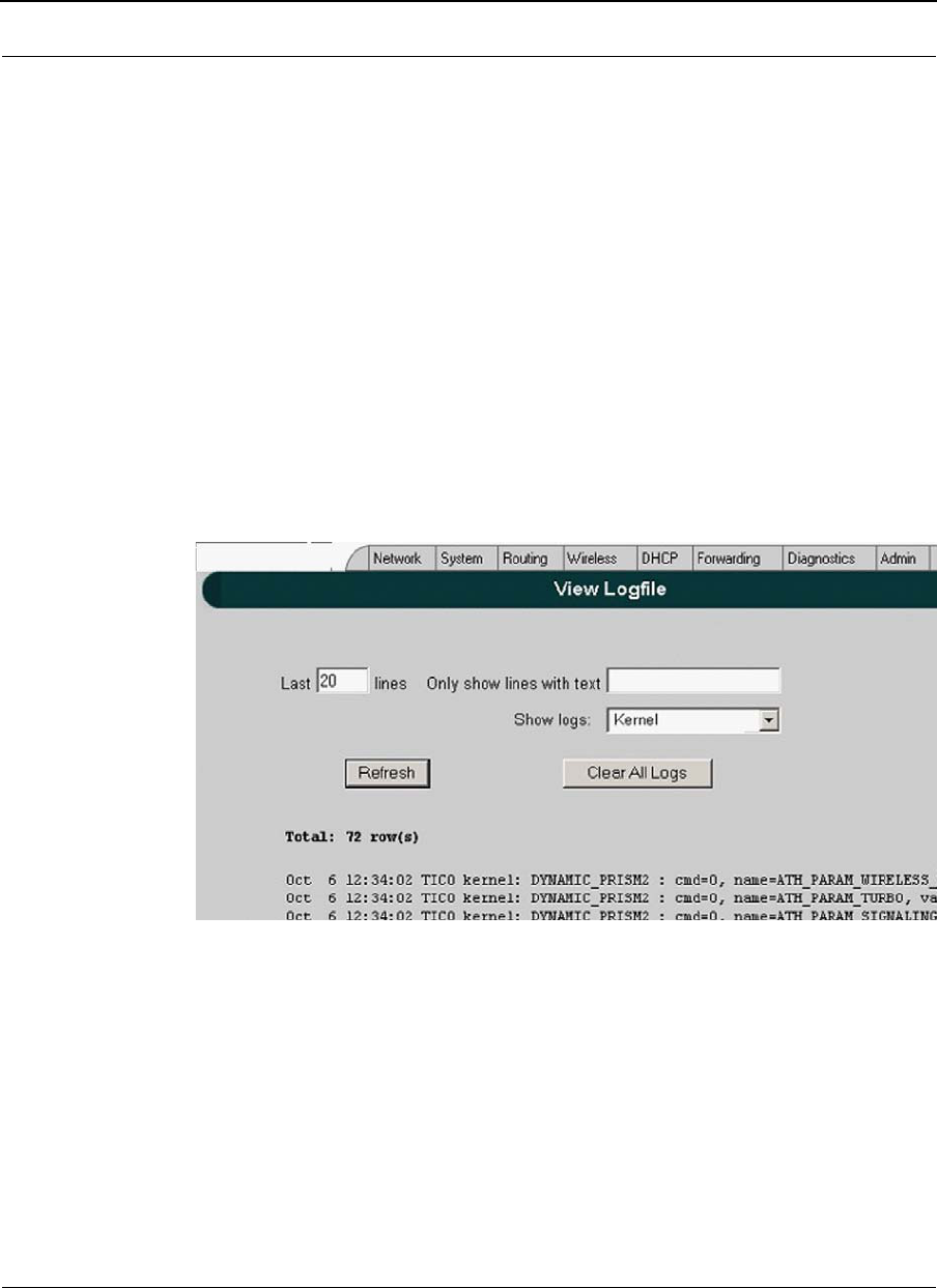
Part # 34357-MNL Rev. B SPEEDLAN 9200 User Guide
3-32
VIEW LOGS
To access View System Logs page, choose Message Log->View Logs from System main
menu.
Figure 3-24: View Logfile
The following controls are available:
•Specify number of last recorded messages to be displayed;
•Filter messages by specifying the text (case insensitive);
•Choose source of message recorder: kernel, wlan, dhcp, snmp, config manager
Jan 29 09:06:51 hostname kernel: wlan[ath0]: Set ath0 operation mode: HOSTAP
Jan 29 09:06:51 hostname kernel: wlan[ath0]: Set ESSID: "SPEEDLAN9200"
Jan 29 09:06:51 hostname kernel: wlan[ath0]: Set Turbo: Disabled
Jan 29 09:06:51 hostname kernel: wlan[ath0]: Set Tx power: 17 dBm
Jan 29 09:06:51 hostname kernel: wlan[ath0]: Set Preamble: Long Only
Jan 29 09:06:51 hostname kernel: wlan[ath0]: Set ACL Policy: OPEN
Jan 29 09:07:03 hostname sshd[319]: Server listening on 0.0.0.0 port 22
Jan 29 09:07:09 hostname rc.local: Starting 'socksvr' ...
Jan 29 09:07:10 hostname rc.local: Starting 'sendfilemc' ...
Jan 29 09:07:10 hostname rc.local: Starting 'ip_recov' ...
Jan 29 09:07:10 hostname rc.local: Starting 'k2status' ...
Log Off
Config Summary

SPEEDLAN 9200 User Guide Part # 34357-MNL Rev. B
3-33
PREDEFINED LOG MESSAGES
Kernel Logs
NatSemi DP8381[56] at 0xc4808000, 00:05:d5:12:67:46, IRQ 11.
00:05:d5:12:67:46, IRQ 11.
Setting full-duplex based on negotiated link capability.
Atheros 5212: mem=0xa0000000, irq=10
Atheros Driver Logs
INFO level logs
wlan: 0.8.4.4 (EXPERIMENTAL)
ath_hal: 0.9.12.14 (AR5210, AR5211, AR5212)
ath_pci: 0.9.4.11
acl: ACL module 1.0 - loaded
Atheros driver version 0.8.4.4 loaded
Atheros driver unloaded
mac acl policy registered
Set atheros device operation mode: {ADHOC,HOSTAP, … }
Set ESSID: {string upto 32 character}
Set Wireless Mode: {IEEE 802.11a, IEEE 802.11b and IEEE
802.11g}
Set Turbo: {Disabled/Enabled}
Set Tx power: {power in dBm}
Set Preamble: { Short & Long ; Long Only }
Set ACL Policy: {OPEN,ALLOW,DENY}
Set signaling rate: {rate in hexadecimal}
Set Rate:
Set RTS/CTS: {Enabled/Disabled} Threshold: {1 up to 2311}
Set Desired Base/Primary MAC: {MAC address}
Set Channel: { channel value }
Set SW/retry: {Disabled/<value>}
Set encryption stuff
Set Key ID: {1-4}; MAC: {MAC address}
Deleted unicast key for MAC: {MAC address}
Deleted shared key ID: {1-4}
Added ACL MAC: {MAC address}
Deleted ACL MAC: {MAC address}
Error Level Logs
Unable to attach hardware; HAL status {<status>}
Failed to allocate descriptors: {<error code>}

Part # 34357-MNL Rev. B SPEEDLAN 9200 User Guide
3-34
Unable to setup a beacon xmit queue!
Unable to register device
ath_pci: 32-bit DMA not available
ath_pci: cannot reserve PCI memory region
ath_pci: cannot remap PCI memory region
ath_pci: no memory for device state
Warning Level Logs
request_irq failed
Ethernet Driver Logs
natsemi dp8381x driver, version 1.07+LK1.0.17, Sep 27, 2002
originally by Donald Becker <becker@scyld.com>
http://www.scyld.com/network/natsemi.html
2.4.x kernel port by Jeff Garzik, Tjeerd Mulder
eth0: silicon revision 0x403
System startup logs
Starting 'socksvr' ...
Starting 'sendfilemc' ...
Starting 'ip_recov' ...
Starting 'k2status' ...
Starting 'frame_mon' ...
Starting 'frame_monw' ...
Starting 'reset_server' ...
Starting 'watchdog' ...
Starting 'inetd' ...
Starting 'rxthresh' ...
Starting 'mesh' ...
Starting 'phopstatus' ...
Starting 'forwarding' ...
Config Manager Logs
INFO level logs
System Logs {Enabled/Disabled}
Mobile client { Enabled/Disabled }
Wireless Security {WEP/WPA/WPA2} { Enabled/Disabled }
SNMP { Enabled/Disabled }
DHCP Server { Enabled/Disabled }
DHCP Relay { Enabled/Disabled }
Access By Manufacturer's Tech Support { Enabled/Disabled }
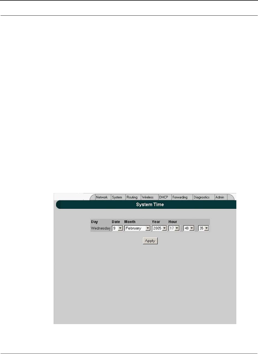
SPEEDLAN 9200 User Guide Part # 34357-MNL Rev. B
3-35
Wireless access to SPEEDSignal { Enabled/Disabled }
Firewall { Enabled/Disabled }
Reset All Configuration to the Factory Default
Configuration File has been uploaded
Configuration File has been installed
Firmware image has been uploaded
Firmware image version {version} has been installed
Reset All Passwords to the Factory Default
Wired Admin { Enabled/Disabled }
Wired Read { Enabled/Disabled }
Wireless Admin { Enabled/Disabled }
Wireless Read { Enabled/Disabled }
Wired Admin password changed
Wired Read password changed
Wireless Admin password changed
Wireless Read password changed
Host name has been changed
{ Ethernet / Wireless } IP address has been changed
SYSTEM TIME
SPEEDLAN 9200 web Configurator provides ability to get/set the system date/time of the
unit. To access System Time, choose System->Time menu.
Figure 3-25: System Time
Log Off
Config Summary
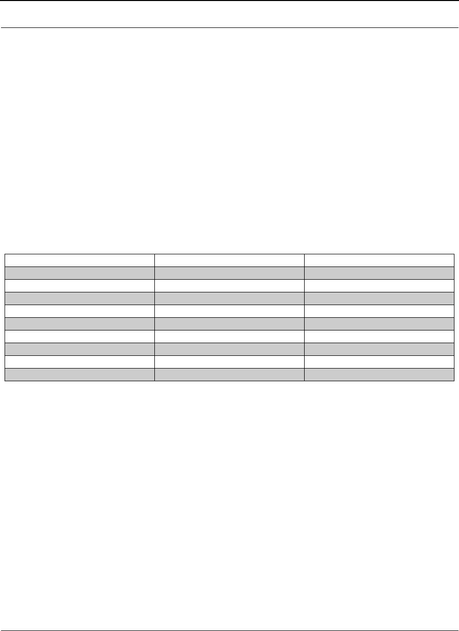
Part # 34357-MNL Rev. B SPEEDLAN 9200 User Guide
3-36
The user is able to set system date/time by choosing values from corresponding combo
boxes he/she wants to set and clicking Apply button. This will change both system and
hardware time. So the new date/time will be there even after power cycle the unit.
Routing Menu
Note that full interoperability with RIP-1 domains requires that the RIP-2 domain be
describable as a collection of classfull networks. This requirement can artificially limit the
use of Variable Length Subnet Mask (VLSM) to support Classless Inter-Domain Routing
(CIDR).
Figure 3-26: Summary Table
The submenus for general routing are specified below:
•Choose Default Gateway to modify the IP address of the default gateway.
•Choose RIP2 to enter settings for RIP.
•Choose Route Table to view the information in the routing table.
•Choose Static Routes to add static routes as additional routes, default routes or
routes that the SPEEDLAN 9200 routers do not contain in their routing table.
Summary Table of Differences Between RIP 1 and RIP2
RIP Version 1 RIP Version 2
Sta tu s Obsolete Current
Ac r o nyms RIP, RI P1 , RI P-1 , RI Pv1 RIP2 , RI P- 2 , RI Pv2
Internet Standards STD 3 4 ( deprecat ed ) STDs 56 and 57
Defining RFCs 1058 2453 and 1722
Ro u t i ng Classfull Classless
Subnet Mask Implicit, fixed length Explicit, variable length
Route Summarizing No Ye s
Authentication None Optional
Updates Distribution Broadcast Multicast
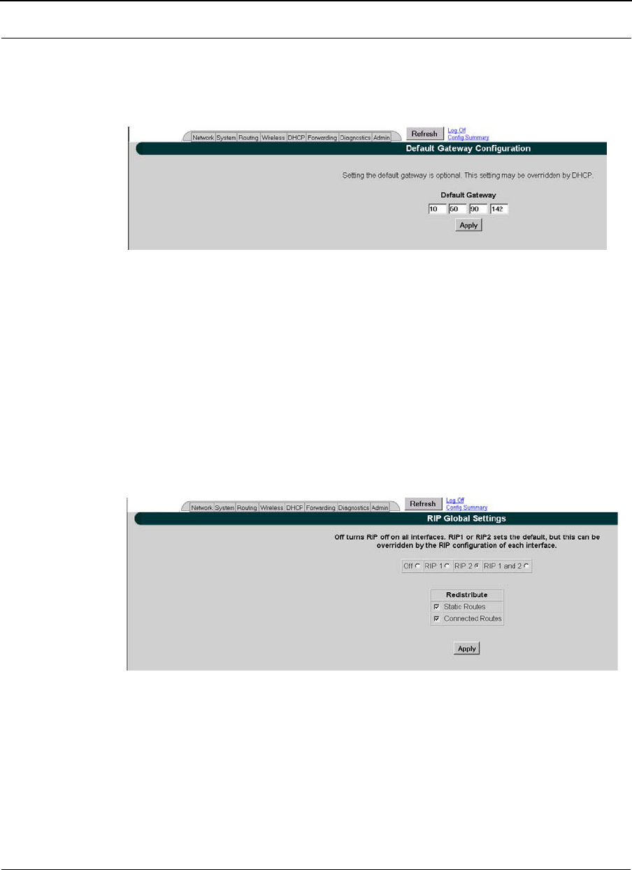
SPEEDLAN 9200 User Guide Part # 34357-MNL Rev. B
3-37
Def Gateway
If you want to modify the IP address of the default gateway, choose Def Gateway from the
Routing menu. The following page will appear.
Figure 3-27: Default Gateway page
Default Gateway: Enter the IP address of the default gateway. This is the "door" where
you want the data to travel. Then, click Apply after modifying information.
Note: Setting the default gateway is optional. This setting may be overridden by DHCP.
RIP2 Setup
To set up global settings for RIP, from the Routing menu, choose RIP2 Setup + Global
Settings. The following page will appear.
Figure 3-28: RIP Global Settings page
The following RIP Global Settings parameters are described below:
•Off: Select to disable RIP.
•RIP 1: Select to enable RIP 1.
•RIP 2: Select to enable RIP 2.
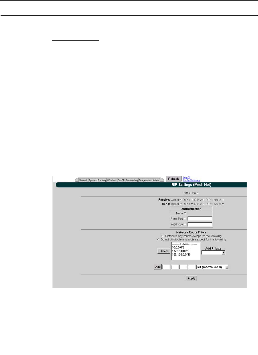
Part # 34357-MNL Rev. B SPEEDLAN 9200 User Guide
3-38
•RIP 1 and RIP 2: Select to enable RIP 1 and RIP 2.
Redistribute section:
•Static routes: Select this check box to redistribute static routes so all routers
know who it has to pass through to get to the destination. Do not select this check
box if you do not want other devices on the network to learn its static route. A
static route is an IP path from one point on the network to another point on the
network.
•Connected routes: Select this check box to redistribute connected routes, which
tells the network what is connected to it. Do not select this check box if you do not
want other devices on the network to know what network(s) the router is
connected to.
Click Apply when you are finished making changes.
RIP Settings
To set up RIP-2 settings, from the Routing menu, choose RIP2 Setup + the interface (e.g.,
Ethernet or StarNet). The following page will appear.
Figure 3-29: RIP Settings page
The following RIP Settings parameters are described below:
•Off: Select this option to disable RIP.
•On: Select this option to enable RIP.

SPEEDLAN 9200 User Guide Part # 34357-MNL Rev. B
3-39
•RIP 1 and RIP 2: Select to enable RIP 1 and RIP 2.
•Receive: This is from the incoming location.
•Send: This is from the outgoing location.
Receive and Send options:
•Global: Click this option to receive/send RIP 1, RIP 2 or RIP 1 & 2 throughout
the entire network.
•RIP 1: Click this option to receive/send RIP-1 from/to the interface.
•RIP 2: Click this option to receive/send RIP-2 from/to the interface.
•RIP 1 and 2: Click this option to receive/send RIP 1 & 2 from/to the interface.
Authentication on RIP-2 MD5
•None: Select this option when authentication is not needed.
•Plain Text: Select this option to enable authentication (security) for legacy
systems.
•MD5 key: Select this option to enable RIP-2 MD5 authentication for security. It
is recommended that you select this option.
Note: Both the RIP-2 MD5 authentication key and Plain Text entries are restricted to
digits or alphabetic characters. Both are entered like a password, but the characters are
visible. The minimum amount of characters entered is 4 and the maximum is 16.
What is RIP-2 MD5 Authentication?
Both RIP-1 and RIP-2 are vulnerable to hostile messages and attacks. This is because
broadcast (RIPv1) or multicast (RIPv2) packets alone lack authentication. When RIP-2 is
used with an authentication algorithm, such as MD5, network security is increased since
the destination receiving the RIP packet knows that it was generated by a reliable source
(i.e., the actual sender of the packet).
RIP-2 MD5 authentication transmits the output of the authentication algorithm rather
than the RIP-2 authentication key. Therefore, the RIP-2 authentication key is never
transmitted over the network and cannot be heard by other routers. This means a router
can determine exactly who sent the message and not assume which router sent it.
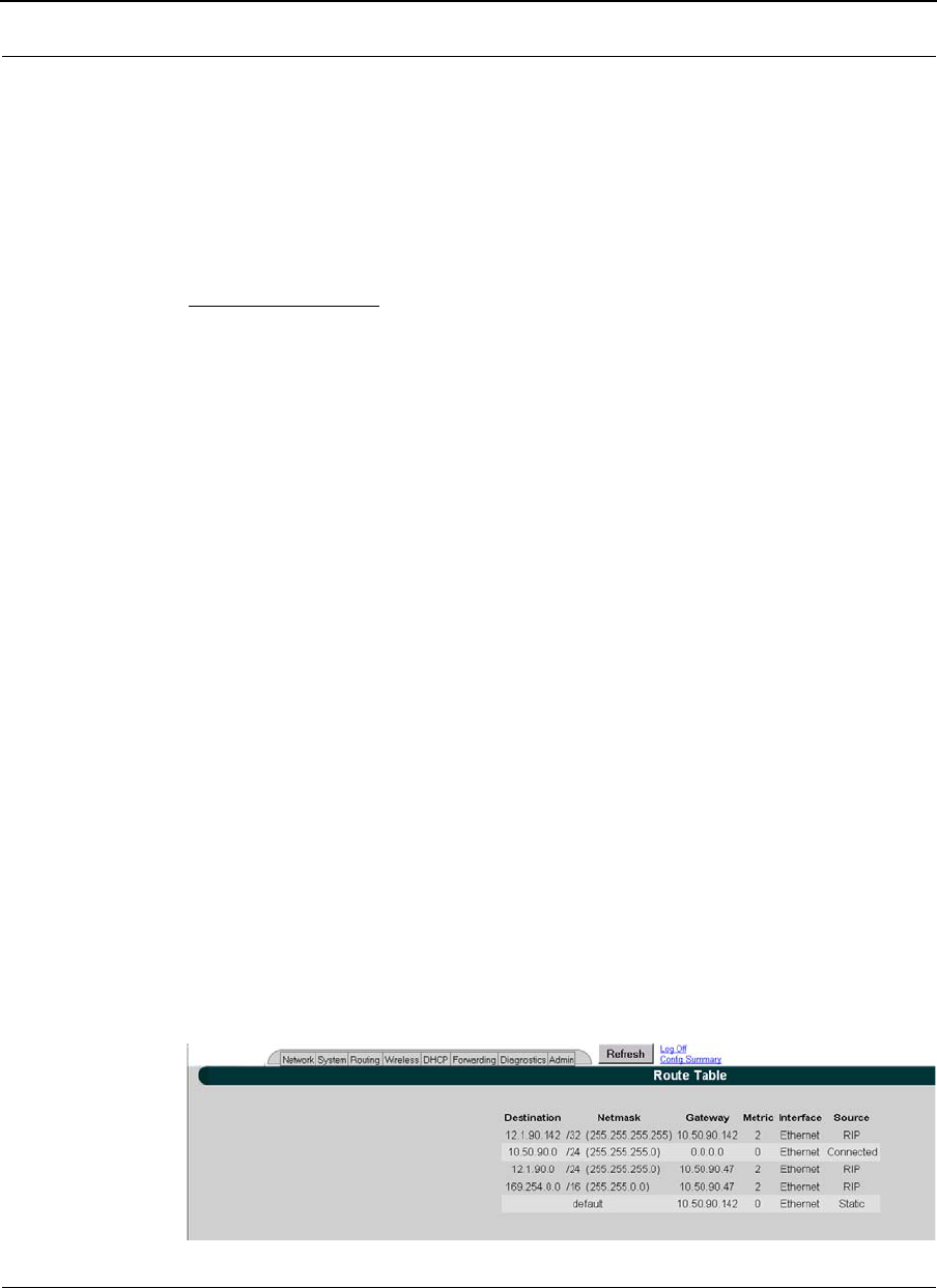
Part # 34357-MNL Rev. B SPEEDLAN 9200 User Guide
3-40
Select one of the following options:
Note: You will need to enter the same authentication type and text / key for all
participating SPEEDLAN 9200 routers.
Click Apply when you are finished making changes.
Network Route Filters:
•Distribute any routes except for the following: Select this option to
distribute all the network routes, except those which are selected in the Filters
box.
•Do not distribute any routes except for the following: Select this option to only
distribute the selected network routes in the Filters box.
•Filters box: Select those filters needed for option 1 or 2 as explained above.
•Add: Click this button to add a network route to the Filters box.
•Delete: Click this button to remove a network filter from the Filters box.
•Add Private: Select the private address from this drop-down list if you want to
include a private address in the Network Route Filters list.
Note: If you want to create your own network route filter IP address, type them in the four
boxes provided below (each box represents the first, second, third and forth octet in the IP
address). Then, click the Add button to add the new IP address to the Filters box.
Click Apply when you are finished making changes.
Route Table
The routing table displays routing information between destinations. To view routing
information, choose Route Table from the Routing menu. The following page will appear.
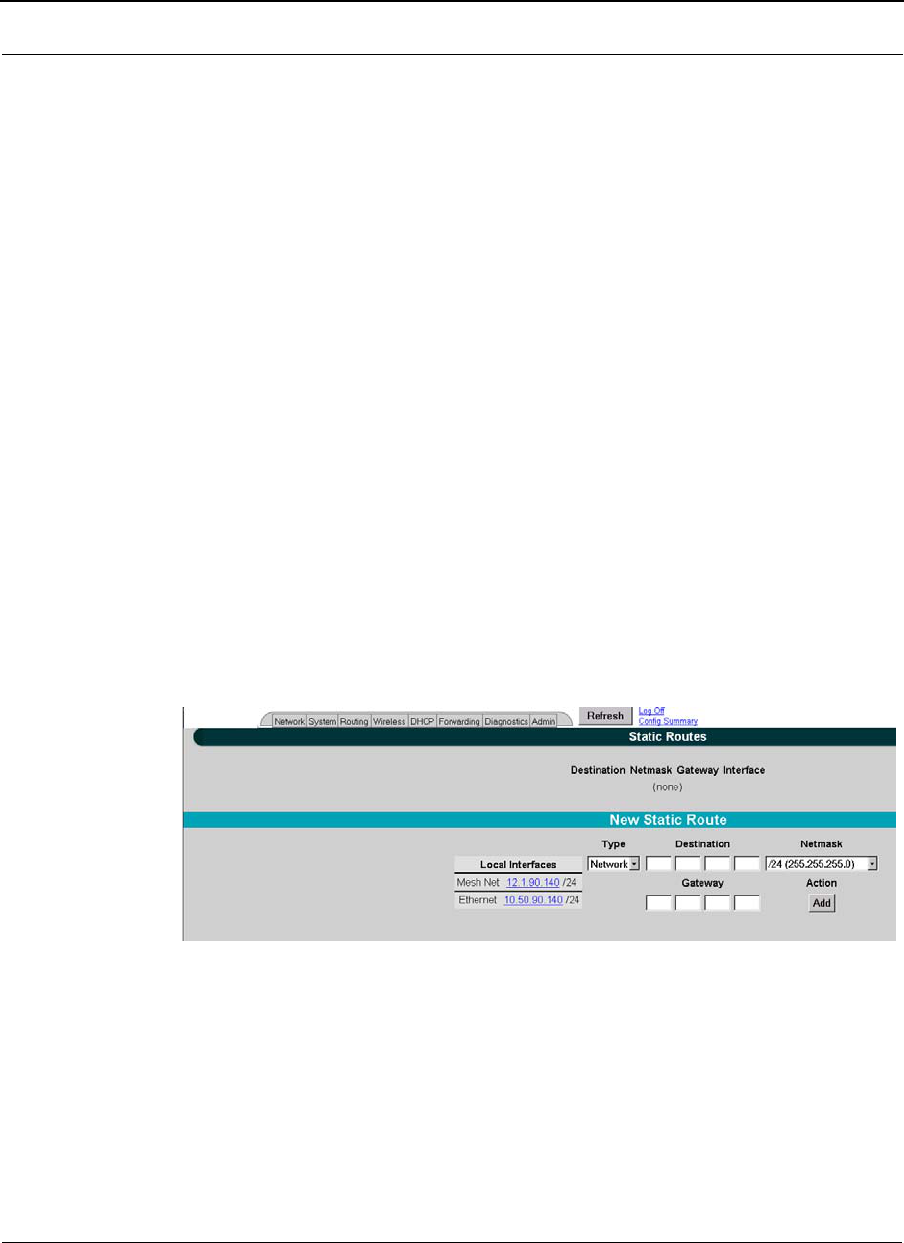
SPEEDLAN 9200 User Guide Part # 34357-MNL Rev. B
3-41
Figure 3-30: Route Table page
Each statistic is defined below:
•Destination: This is the destination network or host.
•Netmask: The netmask is a 4-byte number that masks the network part of the
Internet IP address, so only the host computer part of the address remains.
•Gateway: This is a network point that acts as the "entrance door" to another net-
work. This is the first router that takes you to the designated host (i.e., the next
hop on the network).
•Metric: Metric is a number indicating the preference of one route link over
another. A route link with a lower number will be chosen over one with a higher
number.
•Interface: This specifies which network interface the route will use.
•Source: This lists the how the information is routed to/from the router (e.g., RIP
enabled, static or connected route).
Static Route
The Static Route page allows you to add static routes that the SPEEDLAN 9200 routers do
not contain in their routing table. To open the Static Route page, choose Static Routes
from the Routing menu.
Figure 3-31: Static Route page
Terms for this page are defined below:
•Type: Select either Network or Host from this drop-down list.
•Network: Traffic will be destined either to, from or between network segments.
•Host: Traffic will be destined either to, from or between specific hosts.
•Destination: The destination network or host.

Part # 34357-MNL Rev. B SPEEDLAN 9200 User Guide
3-42
•Netmask: Select the appropriate value for the netmask (also in CIDR format
from /8 to /30) in this drop-down list. This is an abbreviated method of
entering the netmask. For more information, see CIDR Table (For Netmask
Information Purposes), page 3-20.
•Interface: Select the appropriate interface from this drop-down list.
•Gateway: This is a network point that acts as the "entrance door" to another net-
work. This is the first router that takes you to the designated host (i.e., the next
hop on the network).
Note: If you do not want to use a current static route, select the routes you want
to remove and click Delete Selected. To add a new static route, click Add.
•
Configuring the Radio Parameters
Choose one of the options from the Wireless menu:
•If you choose Configuration, you will be able to set the following radio parame-
ters: SSID, wireless mode, channel, signaling rate, turbo mode, Tx power and
preamble. For more information, see Configuration, page 3-43 for more details.
•If you choose Tx Retries, you will be able to set the Transmit Retry Limit and Sig-
naling Rate Fallback. For more information, see Max Tx Retries and Signaling
Rate Fallback, page 3-46.
•If you choose Max Throughput, you will be able to set the Max Transmit Data
Rate in Kb/s. For more information, see Max Throughput (Regulating Band-
width), page 3-48.
Note: If you’re looking for mesh-only functions like Blocked Links, Rx Threshold and Link
Expiration, see the Wireless menu, page 4-7. If you’re looking for the mesh Remote
Control feature, see the Admin Menu, page 4-12. Mesh software/firmware update
instructions are also located under the Admin menu section.
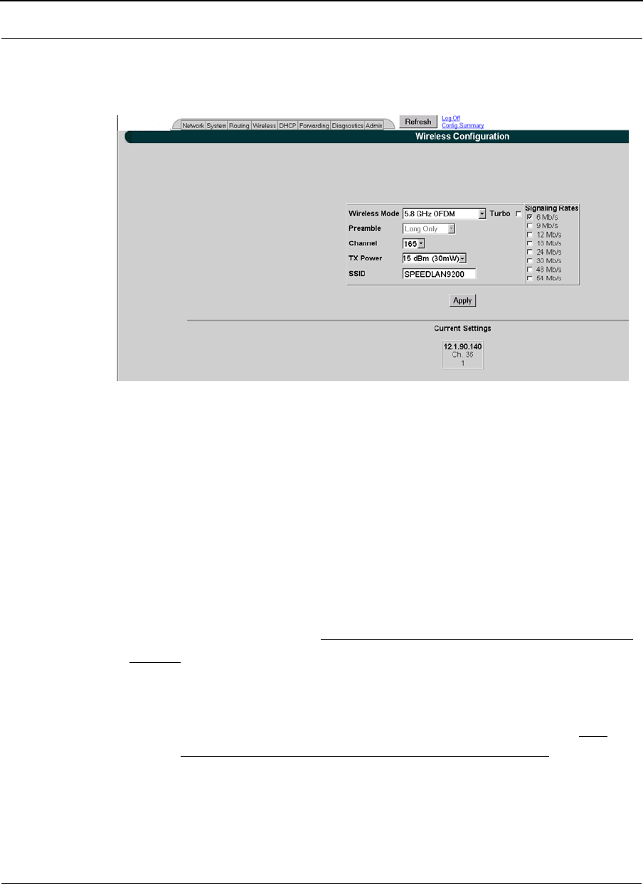
SPEEDLAN 9200 User Guide Part # 34357-MNL Rev. B
3-43
Configuration
1To set these parameters, choose Configuration from the Wireless menu. The Con-
figuration page will appear:
Figure 3-32: Configuration page
2Select one of the following from the Wireless Mode list:
•5.8 GHz OFDM
•2.4 GHz DSSS
•2.4 GHz DSSS/OFDM
•4.9 GHz OFDM
Note: Extended turbo mode provides up to 108 Mb/s, which is automatically selected
when you select 5.8GHz OFDM. If 5.8GHz OFDM is not selected, the "Turbo mode" is
disabled. The Channel drop-down list will populate the appropriate values for the Wireless
Mode you selected.
3You can select a Long, or Short & Long preamble during the transmission pro-
cess between two or more systems from the Preamble drop-down list. This
parameter specifies the preamble setting in 2.4GHZ DSSS mode. There are two
types of preamble, short and long - referring to the length of the sync field. The
default setting is Short & Long. This setting is useful when you cannot determine
the field size of the data being sent. The system will sync itself for both short and
long. Users should select a Long preamble when there is a lot of interference or
noise on the network. (A short preamble is more likely to be used in stable links
.
To apply settings to
remote nodes, select
them and then click
Apply to Selected Nodes.
The screen will populate
those fields for the
Wireless Mode selected.
Therefore, select the
Wireless mode first.
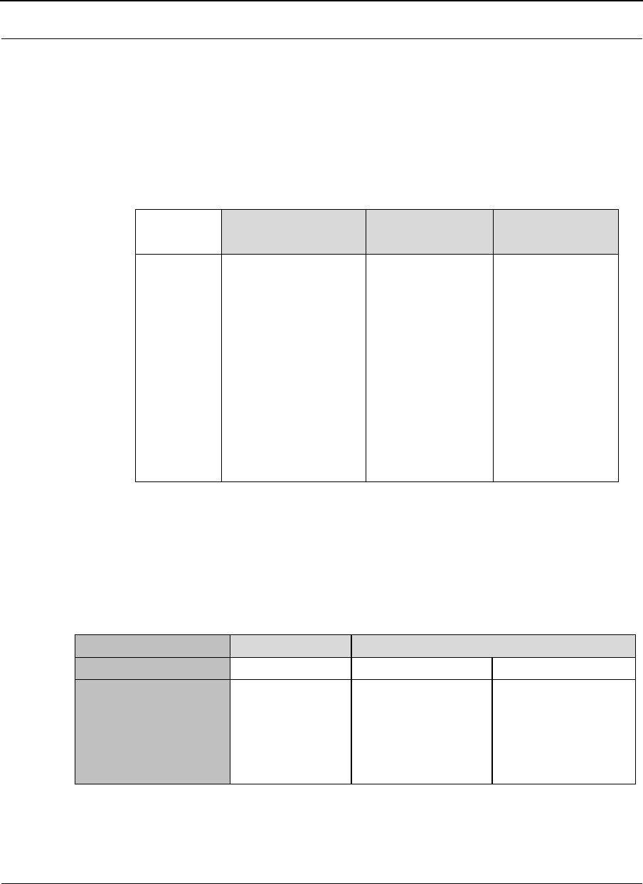
Part # 34357-MNL Rev. B SPEEDLAN 9200 User Guide
3-44
with low noise levels.) The field size of a long preamble is 128 bits and a short
preamble is only 56 bits.
4Select the appropriate channel from the Channel drop-down list. This is the spe-
cific band of frequencies to determine the data path between routers. All SPEED-
LAN 9200 routers expected to communicate in a network must have the same
channel (frequency).
Table 3-2: Channel list
Note: Valid operating channels for the FCC and IC (Canada) are listed in Channels for
IEEE 802.11x, Appendix G-1.
5The following transmit power levels are currently available for 5GHz and 2.4:
Select the appropriate value from the TX Power drop-down list.
Table 3-3: TX Power List
6Check the appropriate Signaling Rate check boxes. This setting refers to the
wireless signaling rate. The SPEEDLAN 9200 routers have different signaling
rates that can be used, depending on the wireless mode selected.
5.8GHz OFDM 2.4GHz
DSSS/OFDM
2.4 GHz DSSS
Channels
supported
149 (5.745GHz)
153 (5.765GHz)
157 (5.785GHz)
161 (5.805GHz)
165 (5.825GHz)
1 (2.412GHz)
2 (2.417GHz)
3 (2.422GHz)
4 (2.427GHz)
5 (2.432GHz)
6 (2.437GHz)
7 (2.442GHz)
8 (2.447GHz)
9 (2.452GHz)
10 (2.457GHz)
11 (2.462GHz)
1 (2.412GHz)
2 (2.417GHz)
3 (2.422GHz)
4 (2.427GHz)
5 (2.432GHz)
6 (2.437GHz)
7 (2.442GHz)
8 (2.447GHz)
9 (2.452GHz)
10 (2.457GHz)
11 (2.462GHz)
Frequency 5.8GHz 2.4GHz
Specific Channels All 1, 2, 10 and 11 3-9
TX Power supported 10 dBm(10mw)
12 dBm(13mW)
13 dBm(20mW)
15 dBm(30mW)
17 dBm(50mW)
10 dBm (10mw)
13 dBm (20mW)
10 dBm (10mw)
13 dBm (20mW)
15 dBm (30mW)
17 dBm (50mW)

SPEEDLAN 9200 User Guide Part # 34357-MNL Rev. B
3-45
The signaling rate is intended to control the transmit rate, depending on the
quality of the link. If the link is getting better/worse, the signaling rate is auto-
matically increased/decreased by one increment. By default, all the supported
signaling rates for the appropriate protocol are selected. An alternative is to
select a subset of the supported rates.
The table below lists the supported Signaling Rates for the wireless modes
offered:
Table 3-4: Signaling Rates
Note: For information about the minimum receiver sensitivity, see: “Minimum Receive
Sensitivity (in dBm) for SL920x” on page 4 of Appendix D.
7Enter the Service Set Identifier in the SSID text box. This is a sequence of
characters that provides a unique name for the wireless network. This field has a
maximum limit of 32 characters. The default value for SSID is
"SPEEDLAN9200".
5.8GHz OFDM Turbo Mode
OFDM
OFDM/DSSS
2.4 OFDM /DSSS
2.4 DSSS
Signaling
Rates
Supported
(in M b/s)
6,9,12,18,
24,36, 48, 54 12,18,24,36,
48,72,96,108 1,2,5.5,11 (DSSS)
6,9,12,18,
24,36, 48, 54
(O FDM )
1,2,5.5,11
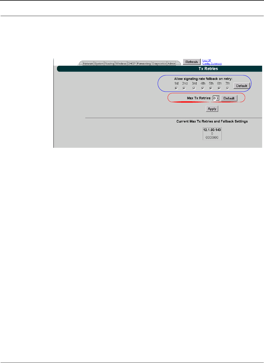
Part # 34357-MNL Rev. B SPEEDLAN 9200 User Guide
3-46
Max Tx Retries and Signaling Rate Fallback
This page includes two features: Max Tx Retries and Signaling Rate Fallback. On the
figure below, Max Tx Retries is circled in red and Signaling Rate Fallback is circled in
blue.
Figure 3-33: Tx Retries and Signaling Rate Fallback page
Note: To apply settings to other remote network nodes, select them and click Apply to
Selected Nodes. If you want to select all of the routers, click Select All.
The default for Max Tx Retries is 6.
Signaling Rate Fallback
During the retransmission of a unicast frame, the signaling rate can "fall back" in order
to increase the chance of reception. Signaling Rate Fallback can occur multiple times for
a single frame. Signaling Rate Fallback occurs from the current rate and will only include
those signaling rates selected on the Channel and Rates page. After ten consecutive
successful unicast frames, the current rate is restored to the highest selected rate.
The Signaling Rate Fallback parameter allows you to control when the signaling rate will
drop, depending on the check box(es) you selected. That is, the check box(es) labeled,
"Allow signaling rate fallback on retry" (circled in blue on previous figure).
The following parameters (check boxes) govern at which point in the re-transmission
process the rate may be dropped:
•1st retry: Will drop signaling rate on first retry.
•2nd retry: Will drop signaling rate on second retry.

SPEEDLAN 9200 User Guide Part # 34357-MNL Rev. B
3-47
•3rd retry: Will drop signaling rate on third retry.
•4th retry: Will drop signaling rate on forth retry.
•5th retry: Will drop signaling rate on fifth retry.
•6th retry: Will drop signaling rate on sixth retry.
•7th retry: Will drop signaling rate on seventh retry.
Here is one example.....
2.4GHz DSSS Example:
The network administrator has configured the allowable transmit signaling rates to be 11,
5.5, 2, and 1 Mb/s. (These values can be selected on the Channel and Rates page under the
Wireless menu.) In addition, the network administrator has selected 7 from the Max Tx
Retries drop-down list and set the signaling rate to "fall back" on the second, fourth, and
sixth retry attempts (as shown in blue on previous figure). When the intended recipient
does not acknowledge a transmitted unicast frame, it will be retransmitted again (after a
short timeout) at the current rate (e.g., 11 Mb/s). If this attempt is also unsuccessful (e.g.,
the receiver did not acknowledge it), the signaling rate will drop to 5.5 Mb/s and another
attempt will be made. If after the third retry, the transmission is still not successful, the
signaling rate will drop to 2 Mb/s for the fourth and fifth retry, and then to 1 Mb/s for the
sixth and seventh retry (if needed).
The recipient sends acknowledgements at the same signaling rate at which it receives
frames. When a frame is successfully transmitted (acknowledgement received in the case
of unicast), the transmitter immediately proceeds to the next frame. The last signaling rate
used to transmit (other than acknowledgements) becomes the current rate. After ten
consecutive unicast frames, the current rate returns to the highest rate selected, if it is not
already at that signaling rate. Note that the receiver's signaling rate is not affected (other
than returning the acknowledgement at a possibly different rate). Each transmitter's
fallback schedule is independent of the signaling rate used by other transmitters.
Max Tx Retries
P-Com recommends that you use this parameter to increase the throughput of your
wireless network. This parameter tells a network node the maximum number of times a
unicast frame can be retransmitted before it is discarded. (A unicast frame is one that is
transmitted to a single node in a network.) This allows a network manager to tune a
network for its particular topology and expected traffic characteristics. The network
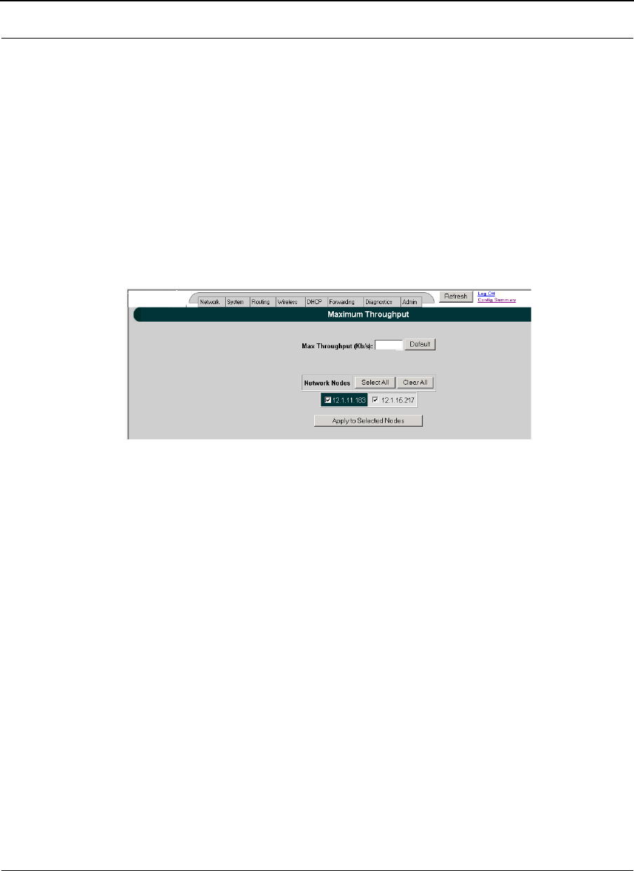
Part # 34357-MNL Rev. B SPEEDLAN 9200 User Guide
3-48
topology, RF environment, number of nodes, throughput requirements, latency
requirements, and type of applications are all factors in choosing an appropriate value for
this parameter.
This parameter can be tuned on a per unit basis in order to optimize network
performance. Click Default to get the default value of 7. You can select a value between 0
and 8 from the Max Tx Retries drop-down list.
Max Throughput (Regulating Bandwidth)
Max Throughput is useful to ISPs that want to regulate the maximum wireless bandwidth
provided from each customer.
Figure 3-34: Max Throughput page
The Max Transmit Data Rate (in Kb/s) defaults are 29300 Kb/s for 2.4GHz & 5.8GHz
OFDM modes, and 6500 Kb/s for DSSS. The range is from 100 to 64,800 Kb/s (6.5 Mb/s).
If you want to use these settings on remote routers, select them and click Apply to Selected
Nodes. If you want to select all of the routers, click Select All.
Bandwidth Limiting
User can enable or disable the "Bandwidth Limiting" on both Ethernet and Wireless
interfaces. When "Bandwidth Limiting" is 'Enabled", user can specify desired maximum
bandwidth on the selected interface. If "Bandwidth Limiting" feature is disabled, the
maximum bandwidth for each interface is:
Ethernet Interface: maximum bandwidth provided by processor.
Wireless Interface: the "throttle" parameter in the wireless driver.
64800
(Range: 100 - 64800)
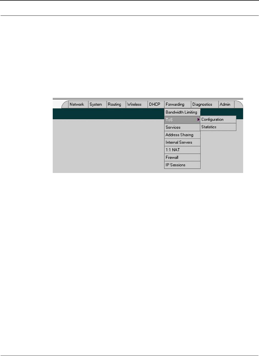
SPEEDLAN 9200 User Guide Part # 34357-MNL Rev. B
3-49
Note: Egress "Bandwidth Limiting" is not applicable to the management traffic of
SPEEDLAN 9200.
Configuration
Forwarding->ToS and Forwarding->Bandwidth Limiting menu items of the main menu in
the Configurator are provided to access the ToS and Bandwidth Limiting configurations.
Figure 3-35: Bandwidth and ToS Menu
Bandwidth Limiting Configuration
Menu Forwarding->Bandwidth Limiting is used to access Bandwidth Limiting
Configuration Page:
64800
(Range: 100 - 64800)
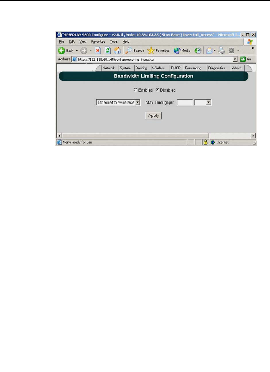
Part # 34357-MNL Rev. B SPEEDLAN 9200 User Guide
3-50
Figure 3-36: Bandwidth Limiting
User can enable or disable the "Bandwidth Limiting" on Ethernet and/or Wireless
interfaces. When "Bandwidth Limiting" is "Enabled", user can specify desired maximum
bandwidth threshold for the selected interface.
ToS
When ToS is enabled, SPEEDLAN9200 prioritizes the packets based on the DSCP
(DiffServ Code Point) in the IP header of the packet to be transmitted to the wireless port.
The source of the packet can be Ethernet port, Wireless port, and CPU. 8 priority queues
are created to map the user traffic to one of the priority queues based on the configured
policies.
When ToS is disabled, one queue is allocated for all the user traffic (non-management).
The global maximum throughput applies to this queue. Global maximum throughput is
configurable if the "Bandwidth Limiting" feature is enabled.
ToS Configuration
ToS is performed via Forwarding->ToS->Configuration submenu.
64800
(Range: 100 - 64800)

SPEEDLAN 9200 User Guide Part # 34357-MNL Rev. B
3-51
User can prioritize traffic according to DiffServ Code Points and Service types. Each line
will show the current mappings of DiffServ Code Points and Services to corresponding
priorities.
To perform the DiffServ Code Point mapping to corresponding priority, "DiffServ
Tagged" link is selected. This link opens the new page for DiffServ Code Points mapping
(see DiffServ Code Point mapping chapter).
To perform the Service type mapping to corresponding priority, "Untagged" link is
selected. This link opens new page for Service mapping (see Service Mapping chapter).
NOTE: All DiffServ Code Points and Service Mappings are applied when ToS is enabled.
DiffServ Code Point mapping
The DiffServ Code Point mapping to priorities is performed by the page below.
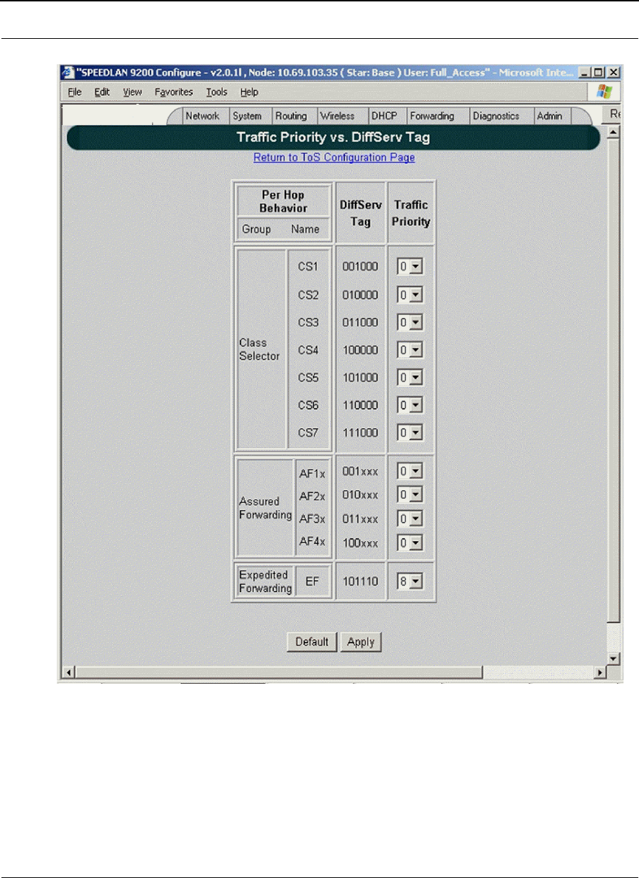
Part # 34357-MNL Rev. B SPEEDLAN 9200 User Guide
3-52
Figure 3-37: DiffServ Code Point Mapping
This page allows user to configure the mapping of the predefined DiffServ Code Points
(DSCP) to corresponding priority from range 1 to 8 (8 is the highest priority and 1 is the
lowest priority.). 0 priority has a special meaning, which is used for un-mapping given
DiffServ Code Point.
64800
(Range: 100 - 64800)

SPEEDLAN 9200 User Guide Part # 34357-MNL Rev. B
3-53
The "Default" button is used to specify the default mapping for all the Codepoints. By
default all DiffServ Code Points are un-mapped except the EF Code Point. The EF Code
Point is mapped to priority 8(the highest).
Link ToS Configuration Page is used to return to the previous page (ToS Configuration
Page).
Rules for Class Selector Codepoints group
A Class Selector Codepoint with a larger numerical value should be mapped to the higher
priority than the Class Selector Codepoint with a smaller numerical value. Entire Class
Selector Codepoints group can be map into a minimum of 2 priorities.
Rules for AF Codepoints group
The mapping of each of four AF classes is performed by the following rules: Within each
AF class three corresponding AF subclasses are mapped implicitly. For example if user
mapped class AF2x then it means that class AF21, AF22 and AF23 will be mapped for the
corresponding priority.
Recommendations for EF Codepoint
EF traffic belongs to fast-track and guaranteed bandwidth service. It is the golden dream
of any application requiring a "First Class" service, special for those that have to deal
with real-time services. Real-time service traffic requires a very fast and safe service for
the moving of data from sources to destinations.
In order to offer this kind of service, it is always recommended to map the EF traffic to
higher priority.
Service type mapping
This page allows the user to map the predefined services to the corresponding priority.
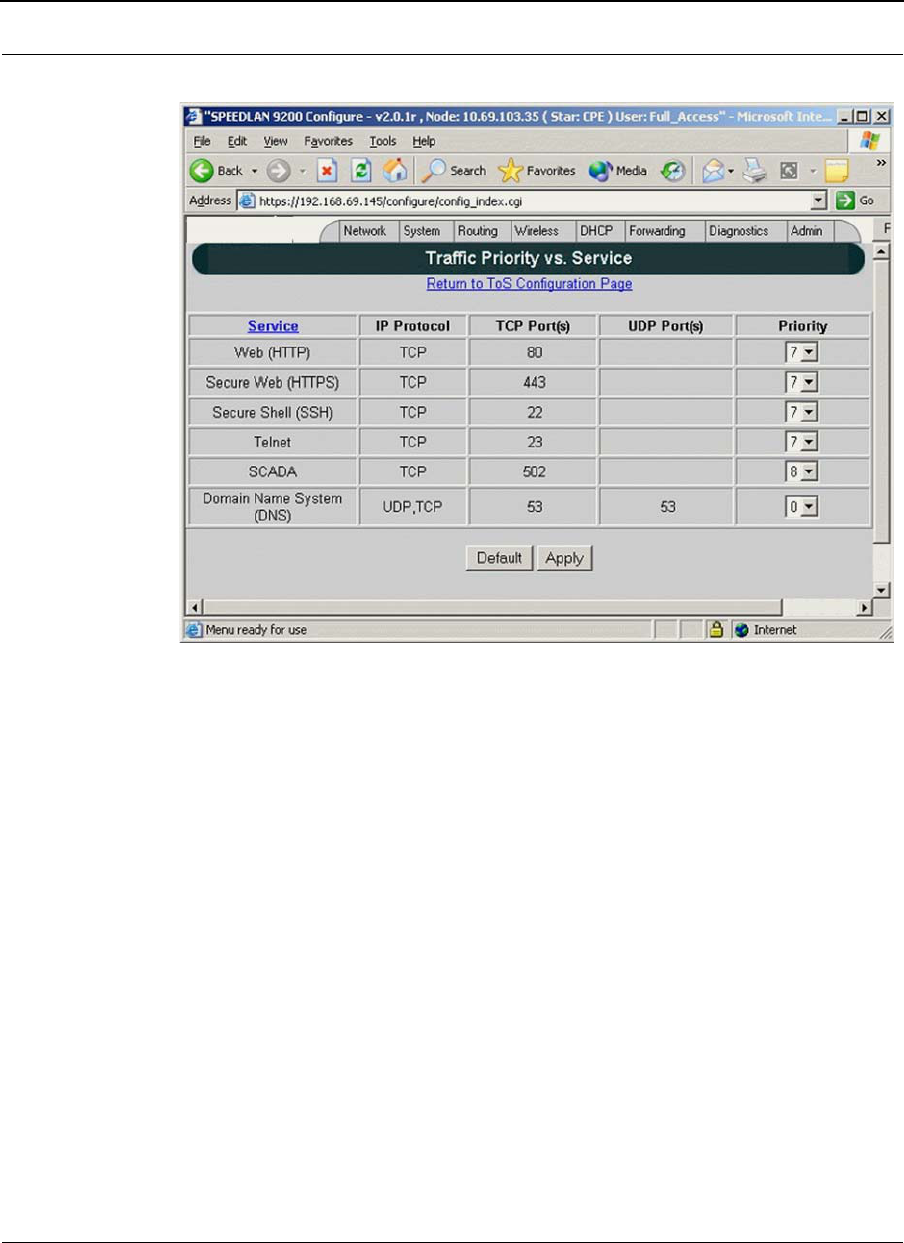
Part # 34357-MNL Rev. B SPEEDLAN 9200 User Guide
3-54
Figure 3-38: Serv Type Map
The "Service" link points to the "Services" configuration page where the user can add the
desired service to the system. The table above is populating with the services as soon as
the new service is added in the system. In order to un-map corresponding Service user
should set the priority to "0" for the corresponding Service. The default service mapping
is illustrated in the picture above. The default mapping is following:
•SCADA to priority 8 (highest)
•HTTP, HTTPS, TELNET, SSH to priority 7 (second highest)
ToS Statistic
ToS statistic is performed via Forwarding->ToS->Statistics submenu. See Figure below.
64800
(Range: 100 - 64800)
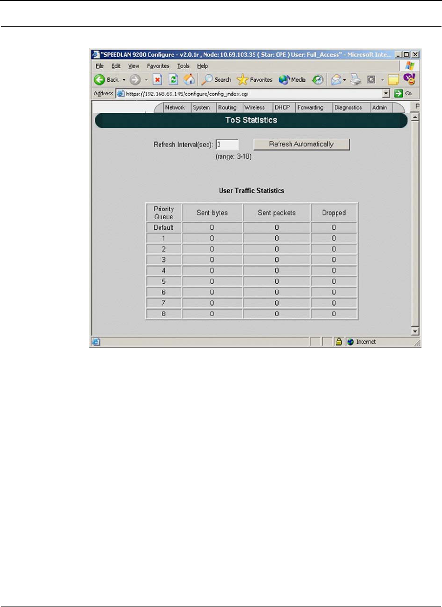
SPEEDLAN 9200 User Guide Part # 34357-MNL Rev. B
3-55
Figure 3-39: ToS Statistic
When ToS is enabled, this page displays the statistic of the ToS priority table. This page
also contains the automatic update mechanism. The refresh interval is user configurable.
DHCP Server Menu
The SPEEDLAN 9200 Configurator allows you to define a DHCP server on the Ethernet
interface. A DHCP server is configured with a table of Ethernet addresses, ranges of IP
64800
(Range: 100 - 64800)
Part # 34357-MNL Rev. B SPEEDLAN 9200 User Guide
3-56
addresses and maps that are assigned to client network devices asking for the network
settings. The DHCP server uses a "lease" to determine the length of time that a device or
interface can use the assigned IP address.
Servers that utilize DHCP resolve security issues, costly IP addressing services, and
compatibility problems. DHCP is a superset to BOOTP, which reduces the agony of
assigning static IP addresses, and also provides advanced configuration options.
How DHCP Assigns an IP Address
This section explains how a DHCP server assigns an address. If you are familiar with this
terminology, skip to Setting Up DHCP and DHCP Relay, page 3-57.
Figure 3-40: DHCP client and server
1The client asks DHCP server for IP address and configuration if needed.
Note: The DHCP server allows IP addresses be assigned dynamically at the remote
building. Distributing these administrative functions to each remote building significantly
reduces the "administrative overhead" traffic that must travel back to the service
provider's headquarters. A DHCP server is configured with a table of IP addresses that
are assigned to client network devices asking for network settings. The DHCP server uses
a "lease" to determine the length of time that a device or interface can use the assigned IP
address.
2The DHCP server assigns an available IP address to the client.
3The client takes the IP address from DHCP server and requests for additional
configuration that is needed.

SPEEDLAN 9200 User Guide Part # 34357-MNL Rev. B
3-57
4DHCP server confirms IP address and configuration.
The SPEEDLAN 9200 Configurator allows you to assign IP addresses via DHCP on the
interfaces.
Setting Up DHCP and DHCP Relay
These instructions will explain how to:
•Configure and Manage the SPEEDLAN 9200 DHCP Server
•Configure DHCP Relay
Important Note about DHCP
The DHCP Server serves IP addresses via the wireless interfaces in addition to the
Ethernet interface. The DHCP Server does not serve other nodes on the same wireless
cell.
For example, for Node A's DHCP server to serve IP addresses via its wireless interface, at
least one of the following must be true:
•Another SPEEDLAN 9200 router on the same cell has DHCP Relay enabled,
and configured to use Node A's DHCP server.
•Beyond the Ethernet of a SPEEDLAN 9200 router on the same cell, there is a
router (wired or wireless) whose DHCP Relay is enabled and configured to use
Node A's DHCP server.
Setting Up DHCP
To set up DHCP, do the following:
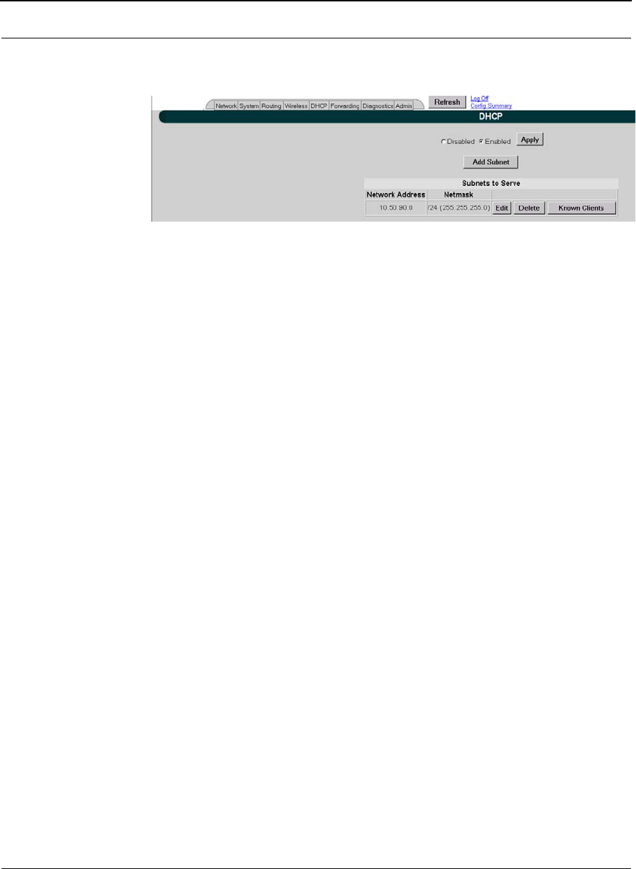
Part # 34357-MNL Rev. B SPEEDLAN 9200 User Guide
3-58
1Choose DHCP from the main menu. Choose Server from the DHCP menu. This
will display the DHCP page, as shown below:
Figure 3-41: Setting UP DHCP
2This is where you can:
•enable or disable the DHCP service
•configure the subnet(s) that the DHCP server will manage
3Select the following information:
•Disabled: Select this option to disable the DHCP server.
•Enabled: Select this option to enable the DHCP server.
•Apply: Click this button to save the settings.
•Add Subnet: Click this button to create a new subnet for the DHCP server to
manage.
Note: If you have any problems configuring the DHCP server, you can look for logged
messages generated by the server. For more information, see Viewing Log Messages,
page 3-63.
Subnets to Serve Section
•Network Address: This is the network address.
•Netmask: This is the netmask for the network.
•Edit: Click this button to modify the subnet on the DHCP server.
•Delete: Click this button to remove the subnet from the DHCP server.
•Known Clients: Click this button if you want to assign specific IP addresses
to specific client computers on a given subnet. This feature will also enable
you to allow or decline specific client requests. For more information, see
Adding a Known Client.

SPEEDLAN 9200 User Guide Part # 34357-MNL Rev. B
3-59
Adding a New DHCP Subnet
1To add a new DHCP subnet, click Add Subnet on the DHCP page. The
following page will appear:
Figure 3-42: Adding a New DHCP Subnet
Notes: After you have added a subnet, you can click the IP address under the "Ethernet/
Mesh Net" Network section, as circled Figure 3-42 on page 3-59, which populates the
following information:
•Network
•Netmask
•IP Start
•IP End
•Default Gateway
Notes:
In most cases, if you use values that are compatible with the appropriate network, you will
only need to change a few values (e.g., the last octet of "IP Start" and "IP End").
When you define the range of IP addresses to be assigned, make sure you do not include
any of the static IP addresses that you have assigned on the network.
2Enter the following elements:
•Network: Enter the network address.
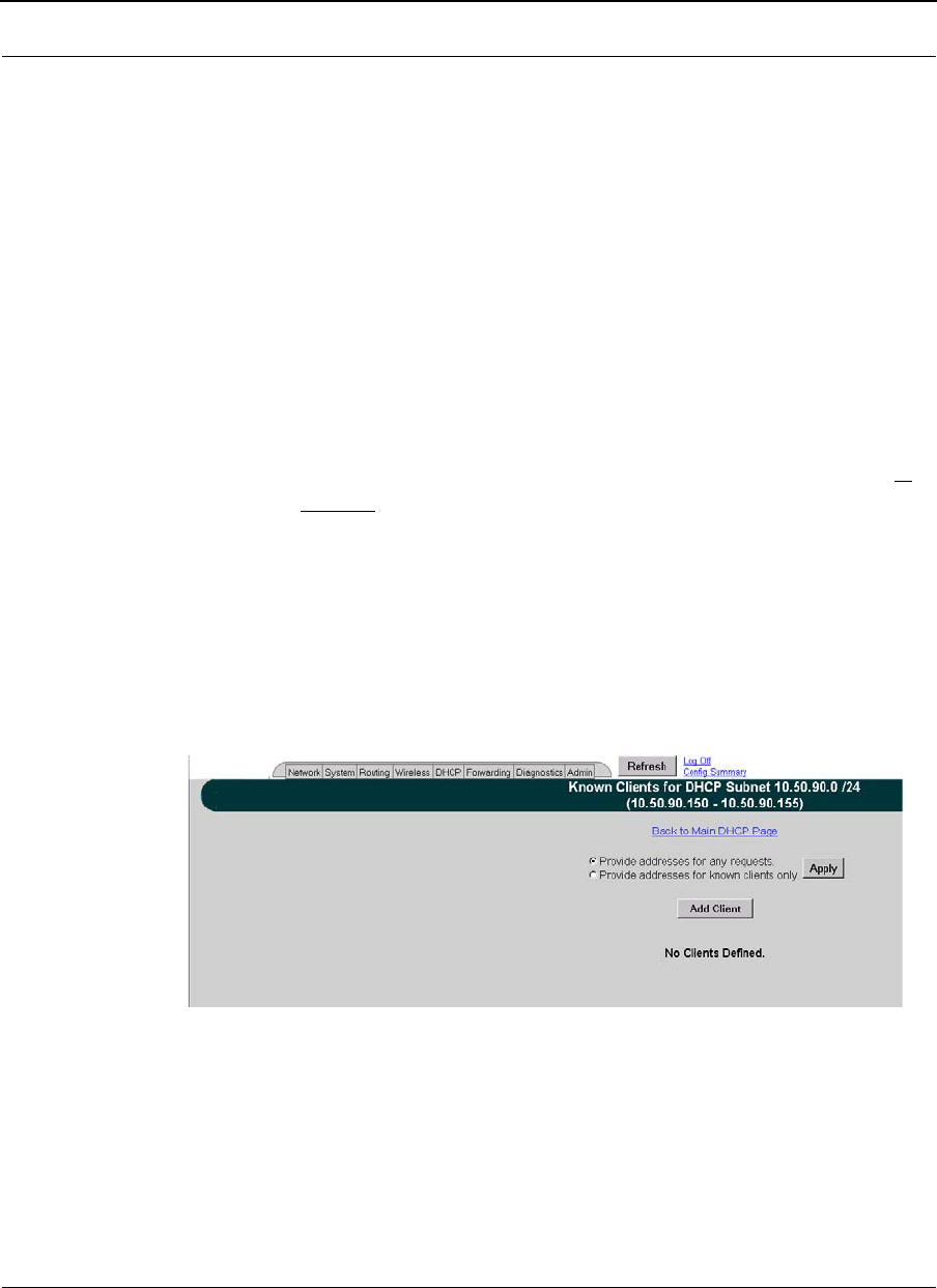
Part # 34357-MNL Rev. B SPEEDLAN 9200 User Guide
3-60
•Netmask: Select the netmask from the drop-down list. This is the 4-byte num-
ber that masks the network part of the Internet Protocol address, so only the
host computer part of the address remains.
•IP Start (Address): This is the start of the block of served IP addresses.
•IP End (Address): This is the end of the block of served IP addresses.
•Default Gateway: This is the default gateway that will be assigned to DHCP
clients.
•Lease Time (in minutes): This is the amount of minutes that the
interface, computer or device can use the assigned IP address. When the
time is up, the IP address will revert to the pool of available addresses and
can be reassigned to another computer. The default is 480. (Entering “0”
means the lease time never expires.)
•Domain Name: This is the internet domain of the organization, such as p-
com.com.
•Domain Name Servers: Enter the IP address of your DNS server (optional).
Prioritize them by listing the DNS to be used first, followed by the second
and third DNS addresses.
•Click Add to implement the changes.
Adding a Known Client
If you click the Known Client button on the DHCP page, the following page will appear:
Figure 3-43: Adding a Known Client
The elements on this page are described below:
•Provide addresses for any requests: Provides addresses to any client.
•Provide addresses for known clients only: Provides addresses to the clients
that appear in this list only.
•Apply: Click to implement changes.
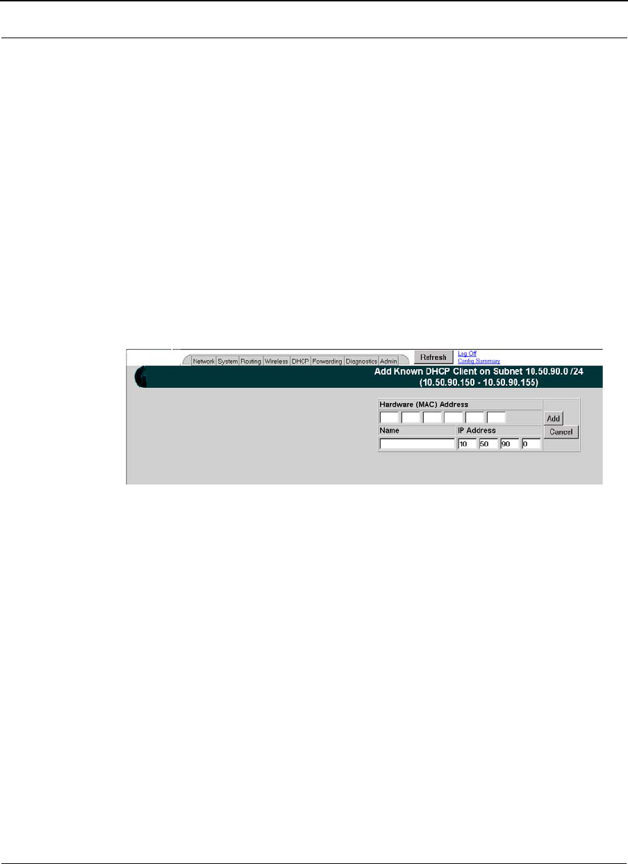
SPEEDLAN 9200 User Guide Part # 34357-MNL Rev. B
3-61
•Add Client: Click this button to add a DHCP client. For more
information, see Adding a DHCP Client.
•Edit: Click this button to edit a DHCP client. Note: Clicking this button dis-
plays similar information explained in the next section, but it allows you to
modify the current client information. The fields will be populated, based on
the client information entered.
•Delete: Click this button to remove a DHCP client.
Note: To go back to the main DHCP page, click the Back to Main DHCP Page link, as
shown on the page above.
Adding a DHCP Client
When you click the Add Client button on the Known Clients for DHCP Subnet page, the
following page will appear:
Figure 3-44: Adding a DHCP Client
This is where you can specify the name of the computer or device, MAC address and its
corresponding IP address that should be assigned to that device at all times. The elements
on this page are described below:
•Hardware (MAC) Address: In a LAN environment each computer
contains its own Medium Access Control (MAC) address, which is the
embedded and unique hardware number.
•Name: Enter the name of the host.
•IP Address: Enter the IP address for the client. Then, click Add to save
changes, or click Cancel to return to the main Known Clients page for this
subnet.
Note: The above fields (Hardware Address, Name and IP Address can be clicked to
automatically populate the textboxes on this page.)
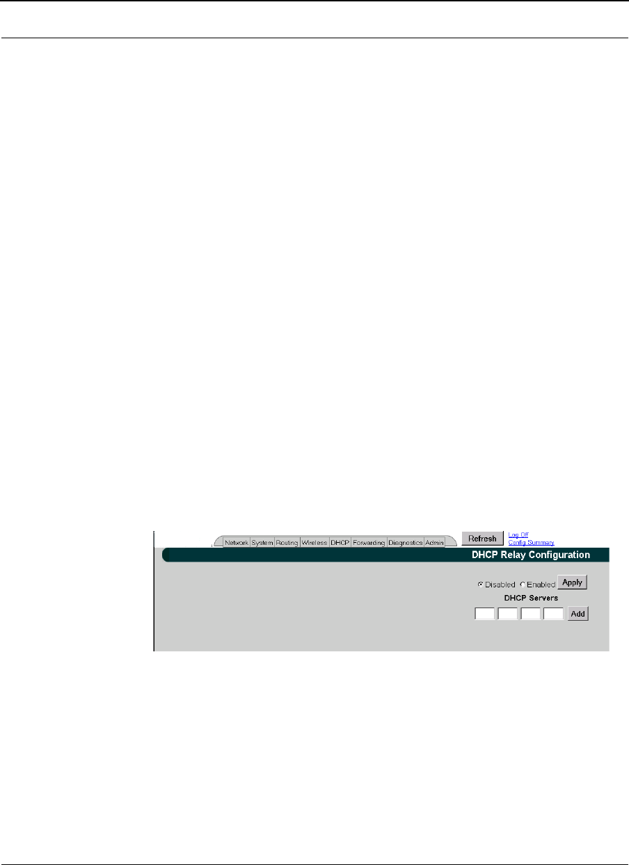
Part # 34357-MNL Rev. B SPEEDLAN 9200 User Guide
3-62
If you need to modify this information later, click Edit on the Known Clients for DHCP
Subnet page.
Note: If you have only one DHCP subnet defined, the DHCP server will offer addresses
from that subnet. If you have two or more subnets defined, offered addresses will be from
the subnet designated as the primary subnet, unless a match is found with a "known
client" defined in a non-primary subnet.
Configuring DHCP Relay
DHCP Relay allows you to configure the SPEEDLAN 9200 to relay (forward) any DHCP
requests originating on the Ethernet interface to a remote DHCP server. This allows you
to use existing DHCP servers to assign IP addresses and other configuration parameters
for SPEEDLAN 9200 routers via their wireless interfaces. If this service is enabled and no
DHCP servers are listed, the SPEEDLAN 9200 will relay DHCP requests to the DHCP
server that the SPEEDLAN 9200 used to get its interface address. If this service is enabled
and the SPEEDLAN 9200 did not use DHCP to get an address for its interface, there must
be at least one DHCP server address listed for this feature to work.
To add DHCP Relay information, do the following:
1Choose DHCP Relay from the DHCP menu. The following page will appear:
Figure 3-45: Configuring DHCP Relay
2Enter the following information:
•Disabled: Click to disable the DHCP Relay service.
•Enabled: Click to enable the DHCP Relay service.
•DHCP Servers: To enter a new DHCP server, enter the IP address and click
Add. This is the IP address of the DHCP server that is offering IP addresses
to its clients.

SPEEDLAN 9200 User Guide Part # 34357-MNL Rev. B
3-63
•Delete: Click this button to remove information related to that DHCP server
address.
3Once you have set up the SPEEDLAN 9200 router, configure the clients to obtain
an IP address from a DHCP server; do this on the PC and not on the router! If
the SPEEDLAN 9200 is the DHCP server, it will get the IP address directly from
it. If the DHCP server is located beyond the SPEEDLAN 9200
routers, the DHCP request will be forwarded to the DHCP server and then
returned to the correct client machine.
If a SPEEDLAN 9200 router is serving as a DHCP relay and it has alias IP addresses, the
IP network information that the SPEEDLAN 9200 relays to the DHCP server will always
be that of the primary Ethernet IP.
Viewing Log Messages
If the DHCP server is not working properly, you can view system log messages by
choosing DHCP Server. Then, choose Log Messages. The page will display log messages
for the DHCP server. Timestamps are also reported in client time. Timestamps track the
date and time for each event in the log.
Forwarding Menu
Use this menu to control how traffic is forwarded through this router. These features are
available under the Forwarding menu:
•Queuing - Use this page to prioritize traffic out its wireless interface. Select the
Enabled option to activate the Priority Queuing feature. This feature is enabled
by default. For more information, see Priority Queuing, page 3-64.
•Services - Defines a network service (e.g., web server, FTP and email server)
between the client and server nodes on your network. When you create a
service, you will be allowed to forward public services inward to the internal
(privately addressed) servers on your network. See Services, page 3-65.
•Address Sharing - Address Sharing uses Network Address Translation (NAT) to
allow you to share public IP addresses with privately addressed network nodes
in order for them to access the Internet. See Address Sharing, page 3-70.
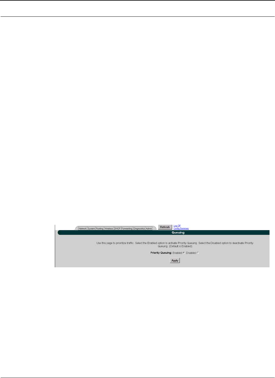
Part # 34357-MNL Rev. B SPEEDLAN 9200 User Guide
3-64
•Internal Servers - Allows an administrator to make a service available from an IP
address, even though the owner of the IP address may not be actually providing
the service. See Internal Servers, page 3-72.
•1:1 NAT - Allows an administrator to statically map a public IP address to the
private IP address of one of the nodes on your network. This is useful when
trying to preserve a limited number of IP addresses on the WAN network. See 1:1
NAT, page 3-73.
•Firewall - The SPEEDLAN 9200 (via the SPEEDLAN 9200 Configurator) allows
you to control incoming and outgoing traffic. A firewall prevents
unauthorized access to a network. Utilizing the SPEEDLAN 9200 Configurator,
SPEEDLAN 9200 routers can increase security and provide additional support
to users of the network. See Firewall, page 3-74.
•lP Sessions - The SPEEDLAN 9200 firewall offers stateful packet filtering. IP
Sessions allows you to view sessions whose state is currently active. See
IP Sessions, page 3-79.
Priority Queuing
Use this page to prioritize traffic out its wireless interface. Select the Enabled option to
activate the Priority Queuing feature. This feature is enabled by default. Select Disabled
to turn off this feature. To open this feature, choose Queuing from the Fowarding menu.
The following page will appear:
Figure 3-46: Setting Up Priority Queuing
1Select Enabled or Disabled.
2Click Apply.
Explanation of this feature
Despite having two physical interfaces, a SPEEDLAN 9200 router can experience
congestion. That is because the interfaces' bit rates are not matched. Specifically, packets
can ingress (enter) the Ethernet interface faster than they can egress (exit) the wireless
interface. If this occurs briefly, it is called short-term congestion, which can cause

SPEEDLAN 9200 User Guide Part # 34357-MNL Rev. B
3-65
increased packet delay and/or jitter. If congestion lasts too long, it can cause packet
discard ("loss"). Long-term congestion in a SPEEDLAN 9200 will typically only occur
when it receives excessive unthrottled UDP traffic at its Ethernet interface. TCP traffic
will self-throttle, typically experiencing only short-term congestion, if any.
A SPEEDLAN 9200 mitigates short-term congestion by providing priority egress queuing
at its wireless interfaces. With priority queuing, packets may be transmitted in a different
order than they were received. This allows favoring network management, VoIP, and
SCADA over SMTP, ftp, and NNTP (for example).
How does Priority Queuing work? The packets are prioritized into a hierarchy of queues,
based on class of traffic. The highest priority queue packets are serviced first. When the
highest queue is emptied, the next lower queue is serviced. The SPEEDLAN 9200 has four
levels of priority queues. Queue 1 (the highest queue serviced) contains "management"
traffic (i.e., RIP, Mesh, SNMP). Queue 2, the next lower queue serviced, contains "real-
time" traffic (i.e., VoIP, Video, SCADA). Queue 3, the next lower queue serviced, contains
"non-real time interactive" traffic (i.e., HTTP, SSH and Telnet). Queue 4 (the lowest level
queue serviced) contains all traffic that doesn't fit into one of the first three queues.
Services
Network "Services" describe specific sessions between clients and servers, servers and
servers, or clients and clients on your network. Examples of servers that provide services
are web servers, FTP servers and email servers. Service definitions allow you to forward
public services inward to the internal (privately addressed) servers on your network.
Note: You can also choose to allow or deny such services between networks or individual
nodes in the firewall section. For more information, see Firewall, page 3-74.
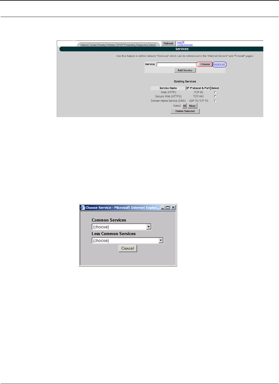
Part # 34357-MNL Rev. B SPEEDLAN 9200 User Guide
3-66
To use the Services feature, choose Services from the Forwarding menu. The following
page will appear:
Figure 3-47: Services page
To enter a service, do the following:
1To display a service in the Service text box, you must click the Choose
button to select a service (circled in red in the previous figure). The service
describes the specific sessions between client and server nodes on your
network (e.g., web servers, FTP servers and email servers).
2The following pop-up will appear, which lists the known services.
Figure 3-48: Choose Service
3Select one of the following:
•Common Services: This list contains the most common type of network
services. (Note: SPEEDView is also listed under this list. It simply lets the
user allow SPEEDView access when the firewall is enabled.) Select the
appropriate service from this drop-down list. Then, click the Add Service
button on the Services page.
•Less Common Services: This list contains less common types of network
services. Select the appropriate service from this drop-down list.
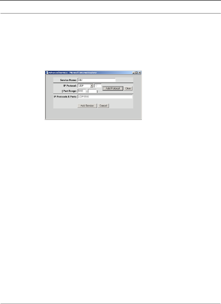
SPEEDLAN 9200 User Guide Part # 34357-MNL Rev. B
3-67
Your selection will be added to the Services page. Then, click the Add Ser-
vice button on the Services page.
Creating an Advanced Service
If you cannot locate the service you want to add, you can define an advanced service by
clicking the Advanced link to the right of the "Choose" button (as circled in blue in
Figure 3-47 on page 3-66). The following pop-up will appear:
Figure 3-49: Advanced Services (adding AIM)
Advanced services can have one or more IP protocols. Under Advanced Services, you
will need to know the name of the service (or it can be unique), the protocol(s) used and
the ports needed to operate the service. For the TCP and UDP protocols, you can define
specific ports, or a range of ports. Enter the following information:
1Service Name: Enter a new name for the service. (In the previous figure, the user
entered "AIM" because the user wanted to add AOL Instant Messenger.)
2IP Protocol: Select an IP protocol for your service. If you select any protocol
other than TCP or UDP, the protocol will be immediately added to the list of pro-
tocols for this service. (In previous figure, the user selected "UDP" because it is
the protocol for AIM.)
3[Port range]: If you select TCP or UDP, you can specify a port or a port range.
Then, click Add Protocol to add that protocol and port to the list. Click Clear to
remove the IP protocol list if you need to start over. (In the previous figure, the
user entered port "5190".) If you are only entering a single port, enter it in the
left Port Range text box.
4IP Protocols and Ports: After clicking Add Protocol, this text box will be
populated with the data, based on what you entered in the IP Protocol, Port num-
ber and Port range text boxes.

Part # 34357-MNL Rev. B SPEEDLAN 9200 User Guide
3-68
5Click Add Service to add the service to the Existing Services list on the
Services page.
Existing Services
The Existing Services list shows all defined services.
•Service Name: The name of the service.
•IP Protocol: The IP protocol by which data sent from one network node to
another is classified (e.g., TCP, UDP, ICMP, OSPF).
•Port: A number used in the TCP and UDP protocols to differentiate streams.
The number is included in the transmitted packets to link the incoming data
to the correct service (e.g., port 80 is used for HTTP).
Note: To remove a service, select its check box and click Delete Selected. Click All to
select all of the existing services. Click None to clear all selections. If an entry has (In
Use) instead of a check box, this means the service is in use and cannot be removed.
Three Features of NAT
NAT Background Info
Network Address Translation (NAT) occurs when there is a translation from one IP
address to another. There are several implementations of NAT - each with their own
purpose. One would choose the type of NAT that suits the task.
The SPEEDLAN 9200 offers 3 features that use NAT: Address Sharing, Internal Servers
and 1:1 NAT. Each is described below.
1. Address Sharing: This feature allows an administrator to share a public IP address with
privately addressed nodes. Typically, this is used to allow outbound connections to the
Internet from hosts who do not have IP addresses that can be reached from the Internet.
In implementing Address Sharing, requests to the Internet would be directed to the
SPEEDLAN 9200. The SPEEDLAN 9200 would then translate the source address and
port to one of its own, and then forward the request on to its destination. The destination
server would return the request to the SPEEDLAN 9200, which would consult its NAT
table, determine which host made the request, change the destination address and port,

SPEEDLAN 9200 User Guide Part # 34357-MNL Rev. B
3-69
and return the completed request. Similar to Internal Servers, this process also creates
the Network Address and Port Translations (NAPT). Address sharing is possible when
units need to act only as clients and do not need to respond to requests. This is a useful
feature if you have a limited number of public IP addresses. You can use this feature to
connect the whole LAN to the Internet using just one public IP address. Here are some
other benefits of address sharing:
•reduce costs by using only one Internet account.
•protect your information by hiding your workstations IP addresses.
•restrict those users you want to access Internet services and resources.
The main Address Sharing page allows you to share the IP addresses assigned to the
SPEEDLAN 9200's network interfaces with all nodes connected to a different network
interface.
2. Internal Servers: This feature allows an administrator to make a service available from
an IP address, even though the owner of the IP address may not be actually providing the
service. Typically, this is used to allow access through a firewall to a protected server. In
implementing "Internal Servers," static NAT rules are established that forward requests
on a given port to a port on a server. For example, a client request to port 80 on the
SPEEDLAN 9200 would be forwarded to an internal web server on port 80. The web
server would then handle the request and return to the client via the SPEEDLAN 9200
router. To the client, it would appear that the reply came from the external address.
3. 1:1 NAT: This feature allows an administrator to statically map a public IP address to
the private IP address of one of the nodes on the network. This is useful when trying to
preserve a limited number of public IP addresses on the WAN network. Otherwise, you
may be forced to split a public network into two smaller networks and incur the penalty of
network and broadcast IP address for both of the new networks. All traffic, regardless of
protocol or port, is translated from the external address to the internal address.
For example, a client request to any port on the "advertised" IP address would be
forwarded to the "internal" IP address of the node. The node would then handle the
request and return to the client the requested data. To the client, it would appear that the
reply came from the external address. This is also referred to as Static NAT.
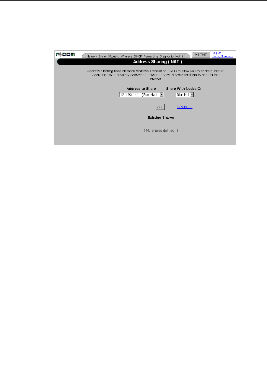
Part # 34357-MNL Rev. B SPEEDLAN 9200 User Guide
3-70
Address Sharing
To share a public IP address with other computers, choose Address Sharing from the
Forwarding menu. The following page will appear:
Figure 3-50: Address Sharing page
The elements on this page are described below:
If you want to share an IP address assigned to the wireless or wired network interfaces,
select the address from the Address to Share list. (In the previous figure, the user entered
"12.1.90.141"). The "Share With Nodes" will automatically be selected (for the StarNet
interface in this example).
Note 1: Addressing Sharing works for connections originating from a host on the "address
to share" interface/network. Connections to actual IP addresses can still be made from the
outside network; those connections will not use the shared address. To prevent this issue,
make sure the firewall is enabled.
Note 2: If changes are made to "address sharing," connections that originated prior to
these changes may still use the previous configuration. The only way to ensure this does
not happen is to reboot the SPEEDLAN 9200 router.
If your WAN interface were the wireless network, you would share the wireless network
interface's IP address with nodes on the Ethernet network. For more options, click on the
Advanced link to the right of the "Add" button.
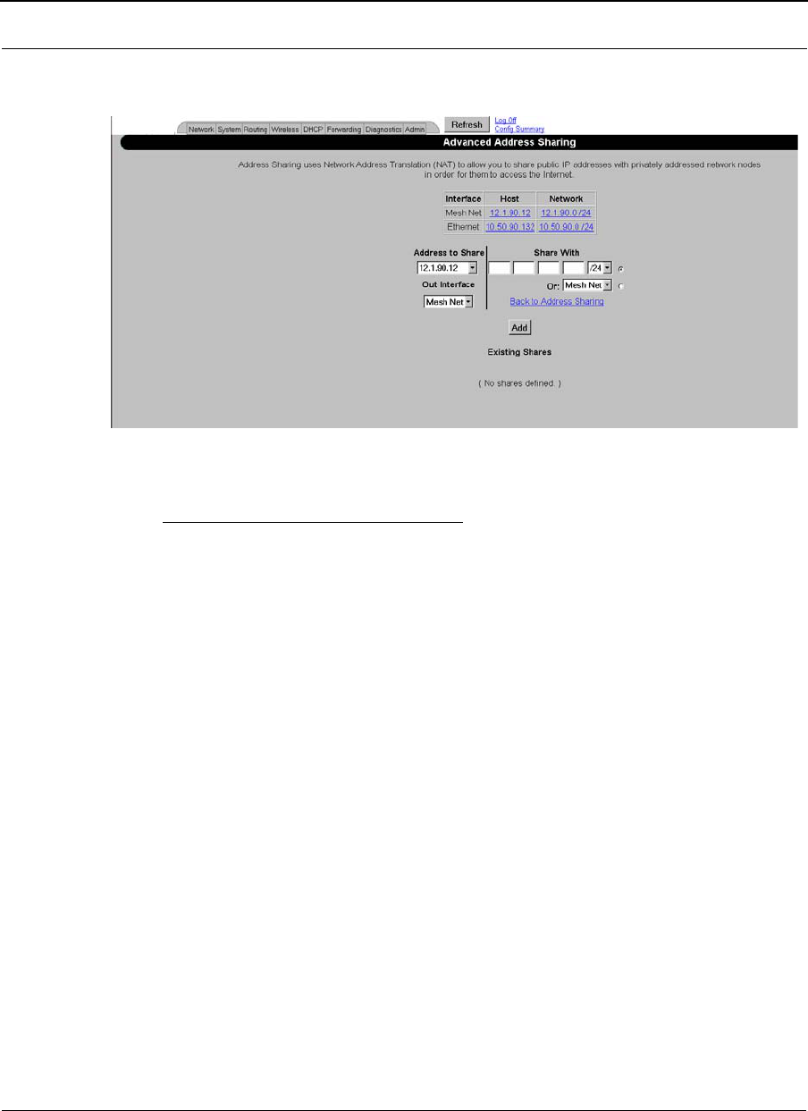
SPEEDLAN 9200 User Guide Part # 34357-MNL Rev. B
3-71
The Advanced Address Sharing page will appear:
Figure 3-51: Advanced Address Sharing
Description of Advanced Address Sharing
The Address Sharing page allows you to share an address with all nodes connected to one
of the SPEEDLAN 9200's network interfaces. This page allows you to narrow down the
IP addresses to a specific network.
•Interface, Host and Network: This table lists the name of the interface, IP
address of the wired and wireless host, and the IP address of the network. If you
click an IP address, it will populate the Share With text box.
•Address(es) to Share: Select a virtual address from this drop-down list. You will
need to select an Out Interface if using a virtual address from the Address to
Share list. This tells the SPEEDLAN 9200 which interface is
acting as the WAN for this operation.
•Share With: Do of the following:
•enter the wired or wireless private IP address where you want the public IP
address to be shared. Select a netmask that specifies a network or host
(/32), or
•select the interface that the private nodes are connected to
(e.g., Ethernet).
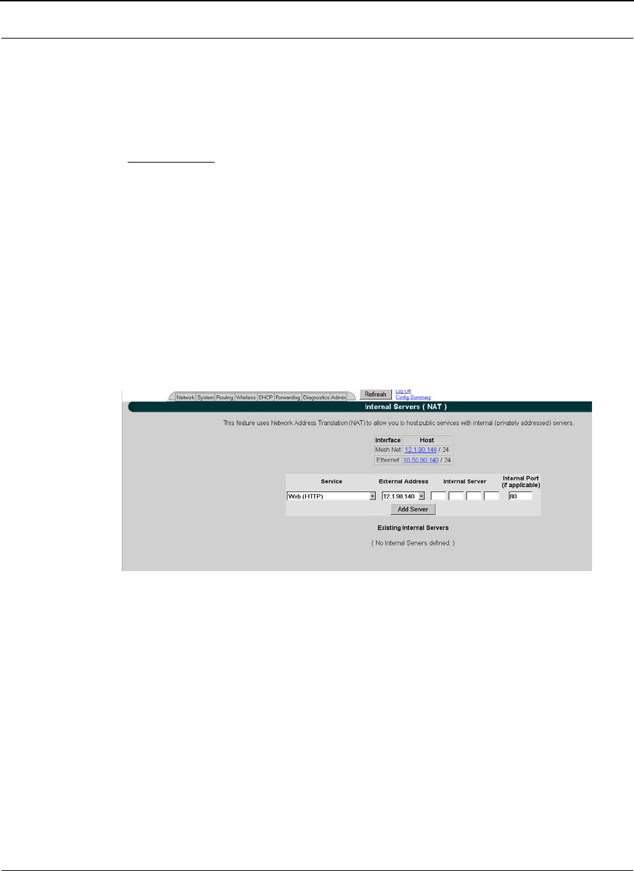
Part # 34357-MNL Rev. B SPEEDLAN 9200 User Guide
3-72
Click Add to implement this setting. This will also be added to the Existing Shares list on
the bottom of this page.
Note: Click the Back To Address Sharing link to return to the previous page.
Existing Shares
This list displays the public IP addresses that are being shared with the private IP nodes.
To remove an existing share, select its check box and then click Delete Selected. Click All
to select all shares. Click None to clear all selections.
Internal Servers
Use this feature to host public (Internet) services with internal (privately addressed)
servers on your network. This allows you to offload services to multiple servers for a given
public IP address. To activate this feature, choose Internal Servers from the Forwarding
menu. The following page will appear:
Figure 3-52: Internal Servers (NAT) page
The elements on this page are described below:
•Interface and Host: This table lists the name of the interface and host IP
addresses assigned to the wired and wireless interfaces. If you click on an IP
address, it will populate the Internal Server text box.
•Service: This is the network service (e.g., HTTP, FTP, etc.) that is provided to the
client. The current services are displayed in the Existing Internal Servers list on
the bottom of this page. (Note: If you want to add to the list of services, choose
Services from the Forwarding menu. Then, follow the directions for Services,
page 3-65.)
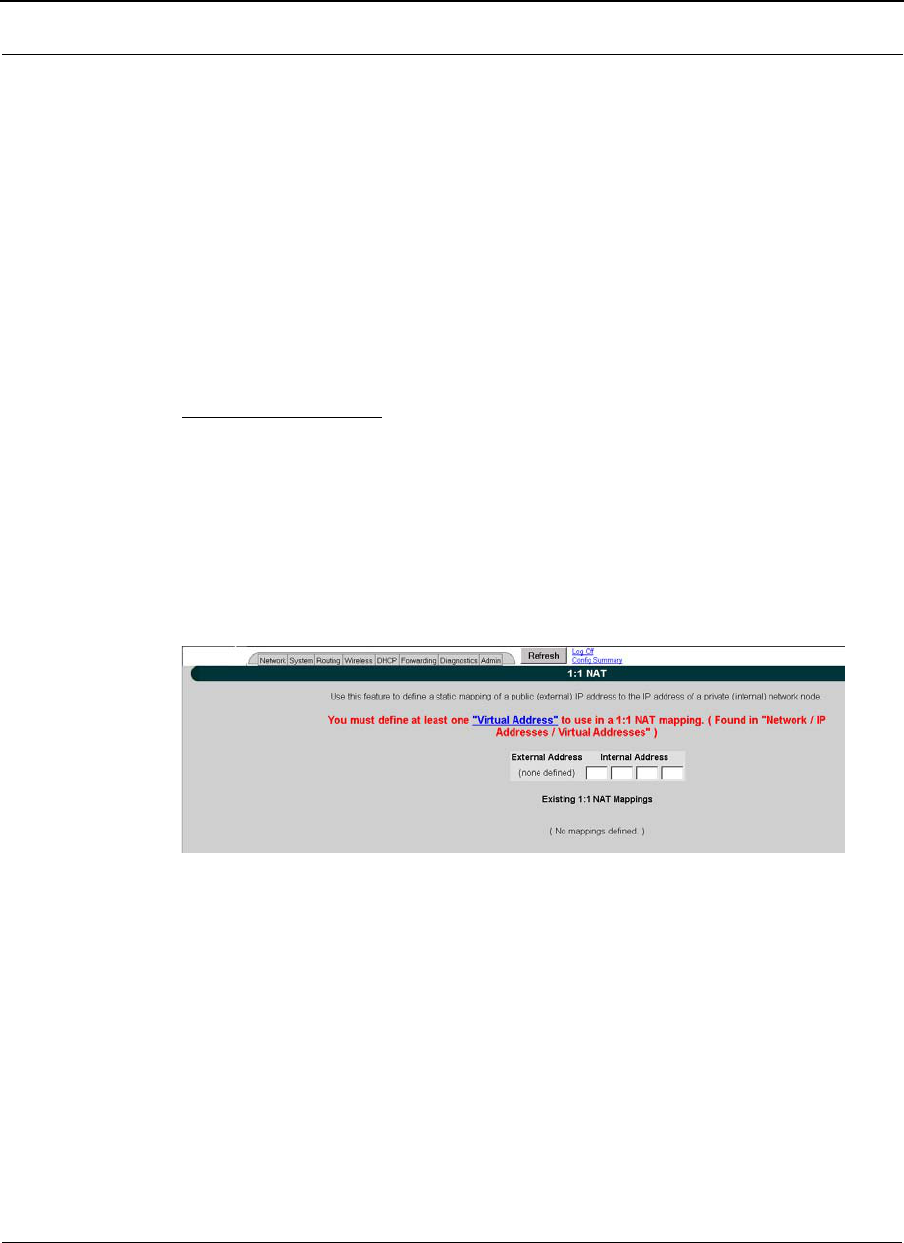
SPEEDLAN 9200 User Guide Part # 34357-MNL Rev. B
3-73
•External Address: Select the IP address where the service will be hosted.
•Internal Server: Enter the IP address of the computer on the network that will
host the service.
•Internal Port (if applicable): If the port is different than the standard for that ser-
vice, enter it here.
When finished making changes, click Add Server. This will add the server to the existing
internal servers list. If the service has multiple TCP or UDP ports defined, a pop up will
appear allowing you to map these to ports on the internal server.
Existing Internal Servers
To remove an internal server, select its check box and click Delete Selected. Click Select
All to select all of the existing internal services. Click None to clear all selections.
1:1 NAT
To access 1:1 NAT settings, choose 1:1 NAT from the Forwarding menu. The following
page will appear:
Figure 3-53: 1:1 NAT page
Make sure you define at least one virtual address prior to using 1:1 NAT. To define a
virtual address, see Virtual Addresses, page 3-22.
The elements on this page are described below:
•Interface and Host: This table lists the name of the interface and host IP
addresses assigned to the wired and wireless interfaces.
•External Address: This lists the IP address on the "outside" network. (In the pre-
vious figure, the user entered "13.13.13.14" for the virtual address.)

Part # 34357-MNL Rev. B SPEEDLAN 9200 User Guide
3-74
•Internal Address: Enter the IP address for the inside or private network. This
address "hides" behind the public IP address you selected. (In the previous
figure, the user entered "192.168.69.88" for the internal IP address.)
Existing 1:1 NAT Mappings
To remove a 1:1 NAT mapping, select its check box and click Delete Selected. Click All to
select all 1:1 NAT mappings. Click None to clear all selections.
Firewall
The SPEEDLAN 9200 (via the SPEEDLAN 9200 Configurator) allows you to control
incoming and outgoing traffic.
A firewall prevents unauthorized access to a network. Utilizing the SPEEDLAN 9200
Configurator, SPEEDLAN 9200 routers can increase security and provide additional
support to the users of the network. In addition, it may help prevent dangerous packets
from intruding on a network that contains sensitive data. It does this by analyzing the
network traffic that is permitted or not permitted to enter the firewall based on
pre-established rules.
The firewall contains a checklist, and it filters traffic that enters and exits the firewall
based on the rules you set (e.g., allowing or denying certain source/destination
combinations). When traffic passes through the firewall, the firewall starts at the top of its
checklist and looks for the rule that matches its criteria. Traffic that meets the criteria in
the checklist will be permitted, and traffic that does not meet the criteria in the checklist
will be blocked. This feature allows you to restrict specific network packets from entering
or leaving your network.
Tips on Creating Rules for Your Firewall
Before you create a rule, make sure you:
•Understand the purpose of the rule. For example, will this rule block all IRC
traffic from the LAN to the Internet? Will this rule allow a remote mail
server to send data at the same time over the Internet to an internal mail
server?
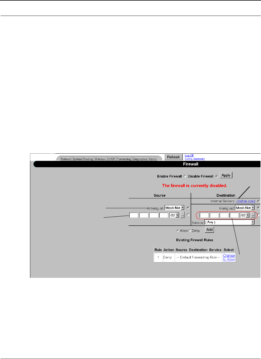
SPEEDLAN 9200 User Guide Part # 34357-MNL Rev. B
3-75
•Do you want the firewall to allow or deny certain traffic? What type of
traffic? What type of IP protocol?
•What is the direction of the traffic: from the Internet to the LAN or from the
LAN to the Internet?
•What IP services will this rule affect?
•Which nodes (or workstations) on the LAN will these rules affect? Make a
mental note of the IP address (those on the private and public LANs) that
these rules will affect.
•Consider the security of the network. For example, once you enable this rule,
which areas of the network will become more vulnerable?
•Will this rule override any other rules you created?
To control traffic flow through the router, choose Firewall from the Forwarding menu. The
following page will appear:
Figure 3-54: Firewall page
Note: When DHCP relay is enabled, it may appear as if DHCP requests get through the
firewall when they are not explicitly allowed. The reason for this is that DHCP requests
come in as link layer broadcasts (which are not filtered by the firewall) and then the relay
server unicasts from the SPEEDLAN 9200 router to the ultimate DHCP server. These
interface
source IP
destination
IP &
netmask
& netmask
Click to
define an
internal server.

Part # 34357-MNL Rev. B SPEEDLAN 9200 User Guide
3-76
unicasts originate from the SPEEDLAN 9200 and thus are not considered to be
"forwarded" by the firewall. Turning off DHCP relay stops this behavior.
The elements on this page are explained below:
•Enable Firewall: Select the Enable Firewall option to activate the firewall fea-
ture.
•Disable Firewall: Select the Disable Firewall option to disable the firewall fea-
ture. Click Apply to activate the option you selected.
Source Section
Arriving on: Select one of the following:
•the interface or
•the IP address/netmask. Then, enter the IP address for the source and select
the netmask.
Note: If you click the "…" button, the physical addresses of the interfaces will be
displayed.
Destination Section
Select one of the following:
•Internal Servers: If there are any internal servers defined on this
SPEEDLAN 9200, you can choose one as the destination in a rule. If there
are no internal servers defined, this combo box will be disabled and you can
click on the Define one link to create an internal server.
•Going Out: Select one of the following: the interface for the destination or
the IP address/netmask. Then, enter the IP address for the destination and
select the netmask.
•Service: Select the name of the service if this rule applies to a single
service. This is the network service (e.g., HTTP, FTP, etc.) that is provided
to the client.
Allow or Deny Action
Select one of the following:
•Allow: Select the Allow option to enable that traffic through the firewall.

SPEEDLAN 9200 User Guide Part # 34357-MNL Rev. B
3-77
•Deny: Select the Deny option to block that traffic through the firewall.
•Add: Click this button to add this rule to the Existing Firewall Rules list.
Existing Firewall Rules
This lists the existing firewall rules, and the firewall will run through the checklist as
explained in the introduction. To remove a firewall rule from the list select its check box
and click Delete Selected. Click All to select all firewall rules. Click None to clear all
selections. To change the Default Forwarding Rule, click the link that either says,
"Change to Allow" or "Change to Deny".
Note: Once you have finished configuring your firewall, reboot the SPEEDLAN 9200
router. This will terminate any undesired connections that may have existed prior to the
firewall configuration. You can verify if such undesired connections exist by opening the
IP Sessions page, which is last function under the Forwarding menu. For more
information, see IP Sessions, page 3-79.
Special Rules for Virtual Addresses
When you create a firewall rule that references a 1:1 NAT mapping or an internal service
using a virtual address, you must specify the internal address as the destination. This is
important to know because the virtual addresses have already been translated to their
defined internal addresses before the firewall examines the packet's destination.
Tutorial: What is happening in this firewall rule set?
As previously explained, a rule set tells the firewall what it can do. The rule set checklist
follows the top-down concept. The first row takes priority, and then follows the second
row's criteria, followed by the third, and so on.
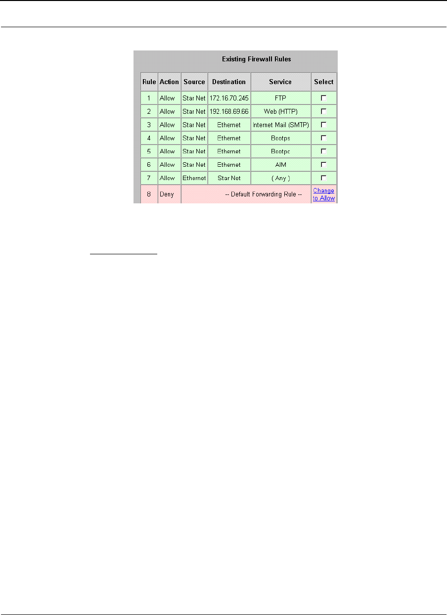
Part # 34357-MNL Rev. B SPEEDLAN 9200 User Guide
3-78
Can you explain what is happening in the example below?
Figure 3-55: Example of Firewall Rules
The explanation:
Rule 1 (FTP server): This rule will allow incoming traffic coming from the Star Net
interface to enter the firewall and go to the FTP server on 172.16.70.245.
Rule 2 (Web server): This rule will allow incoming traffic coming from the Star Net
interface to enter the firewall and go to the web server on 192.168.69.66.
Rule 3 (Mail server): This rule will allow incoming traffic from the Star Net interface to
enter the Internet mail server on the Ethernet interface.
Note about DHCP Rules 4 and 5: DHCP spans both rules 4 and 5. These rules allow
DHCP requests to a DHCP server from the Star Net interface to enter the firewall. The
Bootps service support server requests, and the Bootpc service provides client support for
DHCP.
Rule 4 (DHCP request): This rule allows DHCP requests to a server.
Rule 5 (DHCP reply): This rule allows replies to a client.
Rule 6 (AOL Instant Messenger: AIM): This rule will allow incoming traffic from the Star
Net interface to enter the firewall so clients can run AOL Instant Messenger.
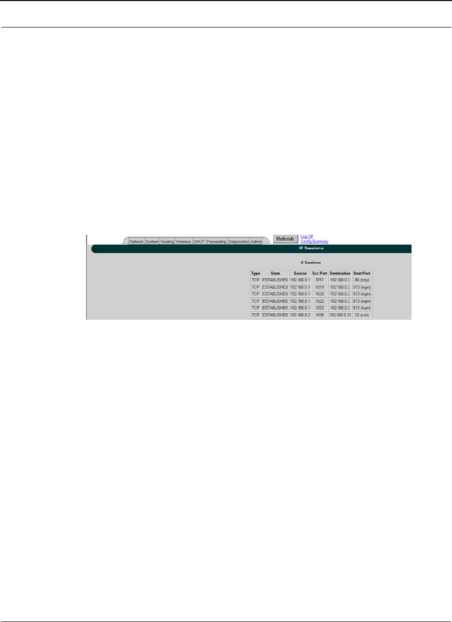
SPEEDLAN 9200 User Guide Part # 34357-MNL Rev. B
3-79
Rule 7 (Anywhere): This rule will allow traffic coming from the Ethernet interface to go
through the firewall via the Star Net interface. The intention is to go anywhere on the
internet or the network).
Rule 8 (Deny incoming traffic): This rule will tell the firewall to deny other incoming
traffic. The firewall will not allow any incoming traffic to go through the firewall.
IP Sessions
The SPEEDLAN 9200 firewall offers stateful packet filtering. IP Sessions allows you to
view sessions whose state is currently active. Choose IP Sessions from the Forwarding
menu. The following page will appear:
Figure 3-56: IP Sessions
This list includes IP sessions terminating or originating on this router, as well as any
forwarded sessions. It is recommended that you open the IP Sessions page after you alter
any firewall rules to verify that all sessions comply with the new rules. Existing sessions
that are not allowed by the new firewall rules will be terminated. You must reboot the
router to remove these types of sessions, or wait for them to finish.
Diagnostics Menu (Troubleshooting the Network)
Choose Diagnostics to troubleshoot network problems.
•Choose Statistics under the Diagnostics menu to view information about inbound
and outbound traffic for the interfaces (or routers).
•Choose ARP Table to locate systems on the LAN that are configured with incor-
rect IP addresses.
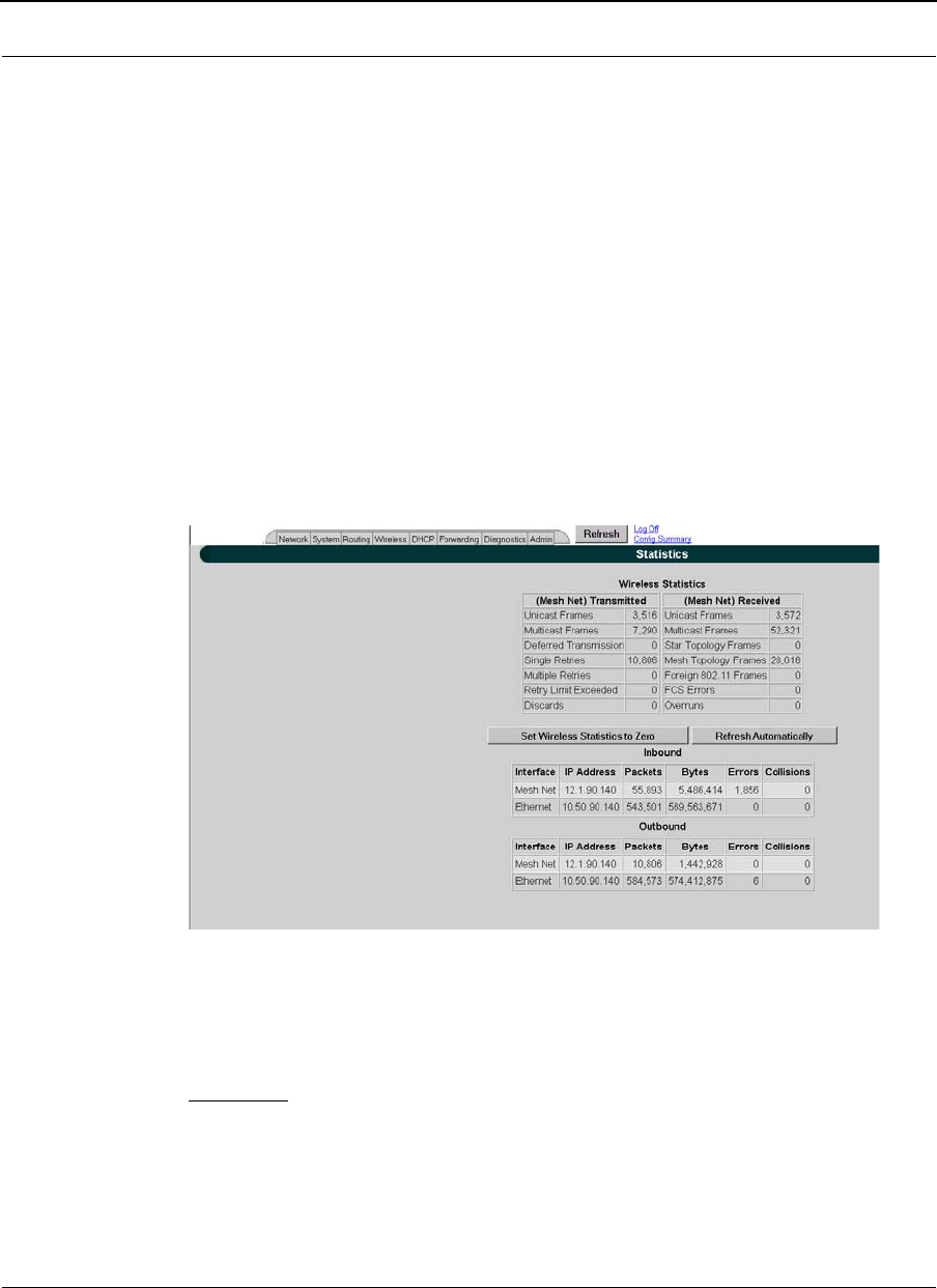
Part # 34357-MNL Rev. B SPEEDLAN 9200 User Guide
3-80
•Choose ICMP Stats to view ICMP messages and errors between the host
servers and gateways.
Special Note about Link & Ping Tests:
Note: If you need to perform a link test to verify that your equipment is communicating
properly at the RF level, SPEEDView is an excellent tool. This process will help you with
the performance evaluation. For more information on how to perform a link test, see The
SPEEDManage User Guide. You can also perform a ping test if need.
Interface Statistics
The Interface Statistics menu lists the current available network interfaces. To view the
statistics of an interface, choose Statistics from the Diagnostics menu. The following page
will appear.
Figure 3-57: Interface Statistics page
Wireless Statistics
Transmitted
•Unicast Frames: Total number of unicast frames transmitted.
•Multicast Frames: Total number of multicast frames transmitted.
•Deferred Transmission: Total number of frames for which one or more
transmission attempt(s) was deferred to avoid a collision.

SPEEDLAN 9200 User Guide Part # 34357-MNL Rev. B
3-81
•Single Retries: Total number of frames successfully transmitted after one (and
only one) retransmission.
•Multiple Retries: Total number of frames successfully transmitted after more
than one retransmission.
•Retry Limit Exceeded: Total number of frames not transmitted successfully
because the retry limit was reached.
•Discards: Total number of frames discarded to free up buffer space.
Received
•Unicast Frames: Total number of unicast frames received.
•Multicast Frames: Total number of multicast frames received.
•Star Topology Frames: Total number of star topology frames received.
•Mesh Topology Frames: Total number of mesh topology frames received.
•Foreign 802.11 Frames: Total number of 802.11 frames received.
•FCS Errors: Total number of frames considered to be destined for this station,
but received with an FCS error.
•Overruns: Total number of frames discarded to free up buffer space.
Inbound & Outbound
Refer to the definitions below for traffic moving inbound or outbound, depending on the
direction of movement. Each inbound and outbound statistic is defined below:
•Interface: The interface on which this entry is effective.
•IP address: This address tells the network how to locate the computers or
network equipment connected to it.
•Packets: A unit of data transmitted between a receiver and a sender. Each packet
contains embedded information, as well as a place to go on the
network (known as the IP address).
•Bytes: The length of the packet.
•Errors: The number of packets that did not reach their destination due to an
error.
•Collisions: The number of packets that did not reach their destination because
two network nodes tried to transmit at the same time.
Note: The statistics are refreshed every time you refresh the web page.
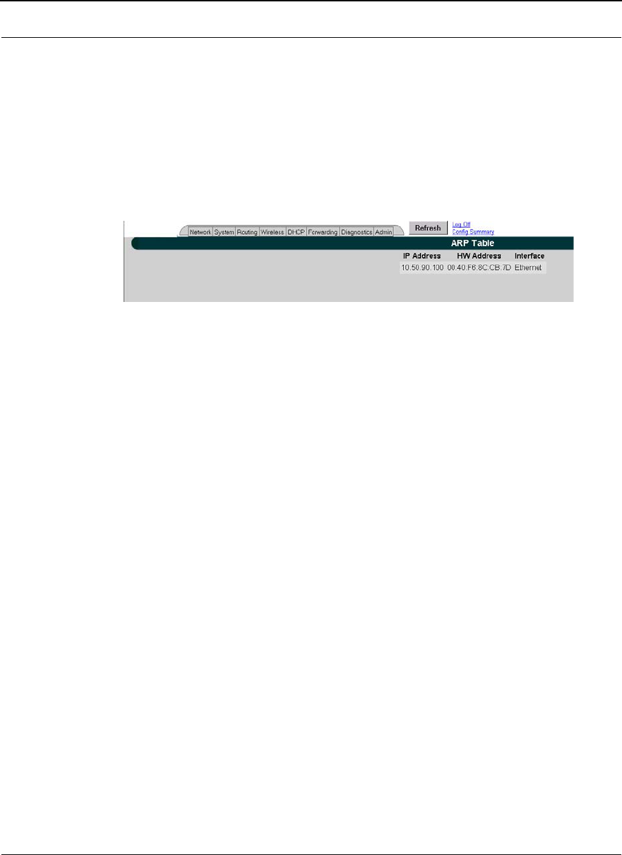
Part # 34357-MNL Rev. B SPEEDLAN 9200 User Guide
3-82
ARP Table
ARP is the abbreviation for Address Resolution Protocol, which maps an IP address to a
machine's hardware address. Network administrators use ARP to locate systems on the
LAN that are configured with incorrect IP addresses. This helps diagnose MAC addresses
that your router knows about.
To open the ARP table, choose ARP Table from the Diagnostics menu. The following page
will appear.
Figure 3-58: ARP page
The ARP statistics are defined below:
•IP address: The IP address corresponding to the media-dependent 'physical'
MAC address.
•HW Address: In a LAN environment each computer contains its own Medium
Access Control (MAC) address which is the embedded and unique hardware
number.
•Interface: The interface on which this entry is effective.
ICMP Statistics
ICMP is the abbreviation for Internet Control Message Protocol. ICMP supplies
messages and error reports for packets that travel between host servers and gateways.
The ICMP stats can be used to diagnose a connectivity problem. If you are trying to ping a
router and you're not getting a response, you can check the "InMsgs" to see if the ping
arrived at the router and just could not get back. This might indicate that the router has no
route back to the originator.
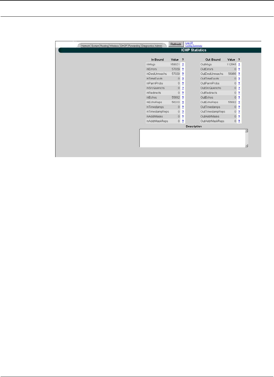
SPEEDLAN 9200 User Guide Part # 34357-MNL Rev. B
3-83
To view ICMP information, choose ICMP Stats from the Diagnostics menu. The following
page will appear.
Figure 3-59: ICMP page
The In Bound statistics are defined below:
•Msgs: The total number of ICMP messages which the entity received. Note that
this counter includes all those counted by icmpInErrors.
•Errors: The number of ICMP messages which the entity received but
determined as having ICMP-specific errors (bad ICMP checksums, bad length,
etc.).
•Dest Unreach: The number of ICMP Destination Unreachable messages
received.
•Time Exceeds: The number of ICMP Time Exceeded messages received.
•Param Problems: The number of ICMP Parameter Problem messages received.
•Src Quenches: The number of ICMP Source Quench messages received.
•Redirects: The number of ICMP Redirect messages received.
•Echos: The number of ICMP Echo (request) messages received.
•Echo Replies: The number of ICMP Echo Reply messages received.
•Timestamps: The number of ICMP Timestamp (request) messages received.
•Timestamp Replies: The number of ICMP Timestamp Reply messages received.
•Addr Masks: The number of ICMP Address Mask Request messages received.

Part # 34357-MNL Rev. B SPEEDLAN 9200 User Guide
3-84
•Addr Mask Replies: The number of ICMP Address Mask Reply messages
received.
The Out Bound statistics are defined below:
•Msgs: The total number of ICMP messages which this entity attempted to send.
Note that this counter includes all those counted by icmpOutErrors.
•Errors: The number of ICMP messages which this entity did not send due to prob-
lems discovered within ICMP such as a lack of buffers. This value should not
include errors discovered outside the ICMP layer such as the inability of IP to
route the resultant datagram. In some implementations there may be no types of
error which contribute to this counter's value.
•Dest Unreach: The number of ICMP Destination Unreachable messages sent.
•Time Exceeds: The number of ICMP Time Exceeded messages sent.
•Param Problems: The number of ICMP Parameter Problem messages sent.
•Src Quenches: The number of ICMP Source Quench messages sent.
•Redirects: The number of ICMP Redirect messages sent.
•Echos: The number of ICMP Echo (request) messages sent.
•Echo Replies: The number of ICMP Echo Reply messages sent.
•Timestamps: The number of ICMP Timestamp (request) messages sent.
•Timestamp Replies: The number of ICMP Timestamp Reply messages sent.
•Addr Masks: The number of ICMP Address Mask Request messages sent.
•Addr Mask Replies: The number of ICMP Address Mask Reply messages sent.
Admin Menu
If you want to limit administrative rights to certain users, choose the Admin menu.
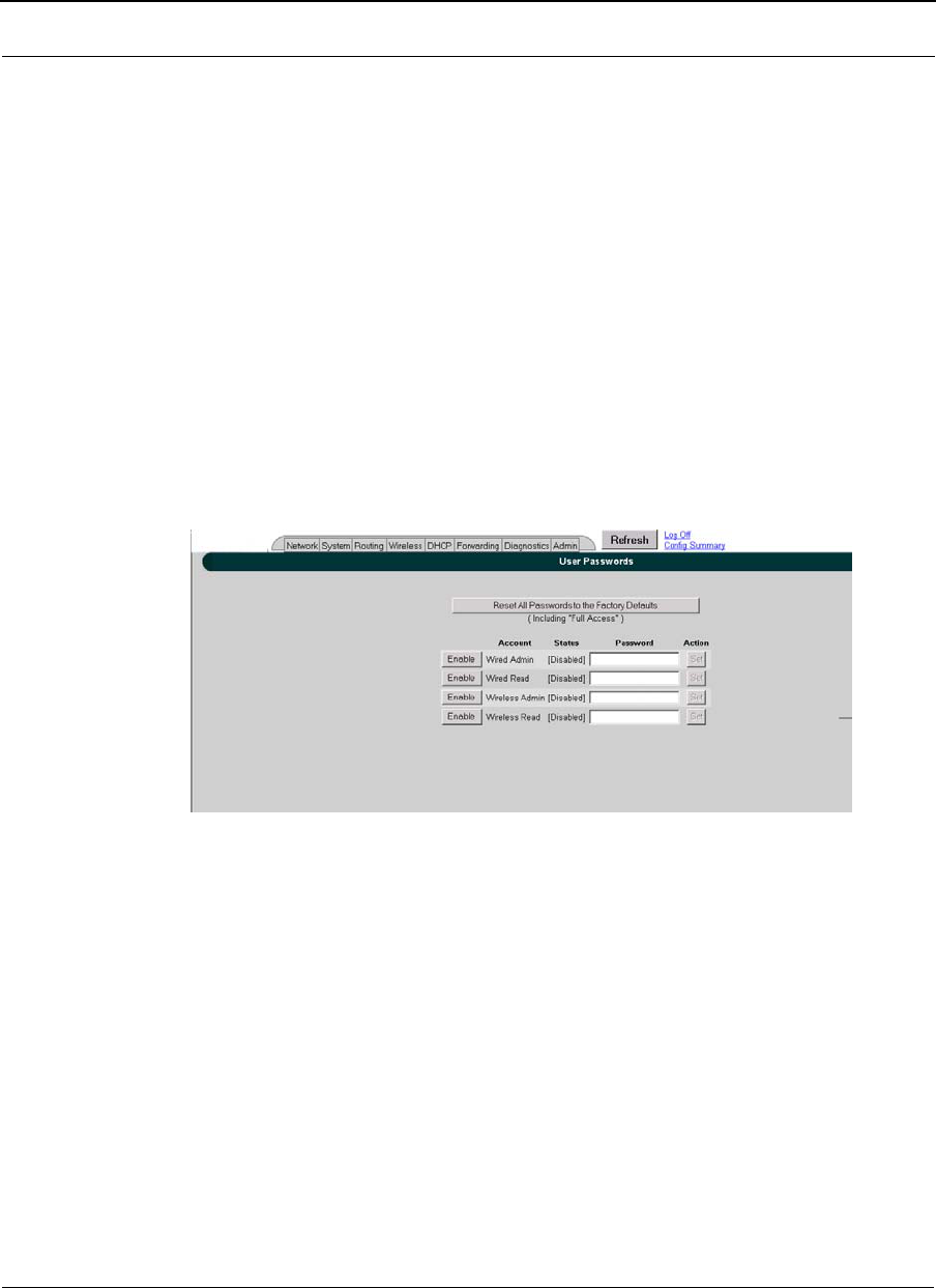
SPEEDLAN 9200 User Guide Part # 34357-MNL Rev. B
3-85
•Choose Users to set passwords for the type of account needed. The user now has
the ability to selectively enable alternate accounts (i.e., accounts other than Full
Access). All alternate accounts will be disabled by default.
•Choose Permissions if you want to restrict certain settings to users.
•Choose Software Update to update the SPEEDLAN 9200 router.
•Choose Support to reset the entire configuration of the SPEEDLAN 9200
factory default settings, enable manufacturer access to the router for advanced
troubleshooting, and enable/disable communication with SPEEDSignal.
•Choose Current Sessions from the Admin menu to view the status of a
session or to terminate it.
User Configuration Passwords
When logged on with the full-access password, you will see the Users page. To activate
this page, choose Users from the Admin menu. The following page will appear.
Figure 3-60: User Configuration page
The classes of users are described in Classes of Users (and Passwords), page 3-10. The
User Configuration page allows you to set a password for each user account in the
SPEEDLAN 9200 Configurator.
The user now has the ability to selectively enable alternate accounts (i.e., accounts other
than Full Access). All alternate accounts will be disabled by default.
1Do one of the following:
•Click Enable to enable the account.
•Click Disable to disable the account
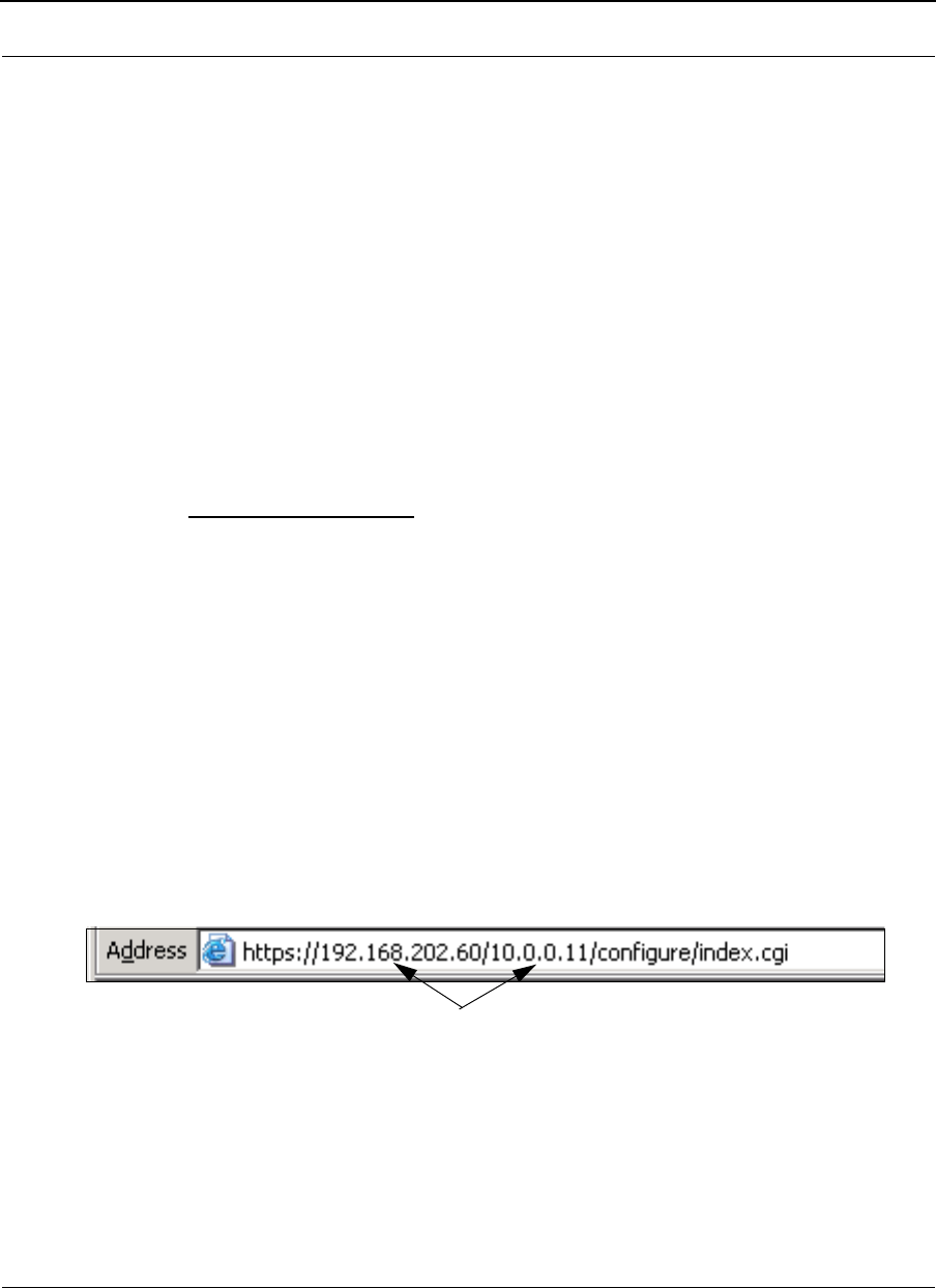
Part # 34357-MNL Rev. B SPEEDLAN 9200 User Guide
3-86
2Enter the password for the user account in the textbox provided. The minimum
password length is 8 characters. The maximum password length is 16
characters (including the underscore character or spacebar).
3Click Set.
To revert to factory default settings, click Reset to Factory Defaults.
Software Update
The Software Update zip file (found on the www.wavewireless.com web site under the
Support + Firmware link) will contain a document describing the recent changes and any
other additional information needed to perform the update.
•For updating the software on a mesh router, see Software Update, page 4-12.
Proxy Mode Warning
Warning! Do not use Proxy mode when performing the update. Update from the location (host) where
you are connected. If you are not directly connected, then you are proxied to another host and the
update will not work. There is a limitation of proxy mode that restricts a transaction to 60 seconds.
If the update takes longer than 60 seconds, which it frequently does, the update will be stopped.
How do you tell if you are directly connected to the host? Look in the Address bar on your Internet
browser. If you only see one IP address in the Address bar, you are directly connected. However, if
you see two IP address in the Address bar, as shown in the following figure, then you are in "Proxy" mode.
displays two IP addresses (Proxy mode)
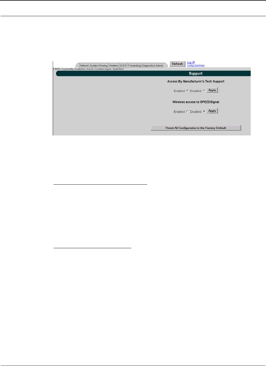
SPEEDLAN 9200 User Guide Part # 34357-MNL Rev. B
3-87
Support
This page displays some support function features for Technical Support, Access to
SPEEDSignal (for Pocket PC) and Reset to Factory Default. You can access these
features by choosing Support from the Admin menu. The following page will appear:
Figure 3-61: Support page
The elements on this page are explained below:
Access By Manufacturer's Tech Support
This is where you can enable the manufacturer to access the router for advanced
troubleshooting (by choosing the Enabled option). The factory default is disabled and
should remain disabled unless requested by a manufacturer's technical support
representative (by choosing the Disabled option). Click Apply when finished.
Access to Wireless SPEEDSignal
This feature is used to enable or disable Pocket PC PDAs to communicate with
SPEEDSignal.
•Click the Enabled option to enable communication with SPEEDSignal.
•Click the Disabled option to disable communication with SPEEDSignal. Click
Apply when finished.
Reset to Factory Default
If you need to reset the entire configuration of the SPEEDLAN 9200 to factory default
settings, click Reset All Configuration to the Factory Default.

Part # 34357-MNL Rev. B SPEEDLAN 9200 User Guide
3-88
Current Sessions
Figure 3-62: Current Sessions
Current Sessions is activated by choosing Current Sessions from the Admin menu. This
page displays the active actions for the web server. It displays who is logged on and also
lets you terminate the session by clicking the Terminate link.
CONFIGURATION DOWNLOAD/UPLOAD
Configuration Download/Upload feature is supported in SPEEDLan 9200 to allow user
to:
•Download the all the current configuration settings to a file on the local host.
•Upload the configurations that are stored in the configuration to the specific
SPEEDLAN 9200 unit.
To access Configuration Download/Upload page, choose Admin->Configuration from
System main menu
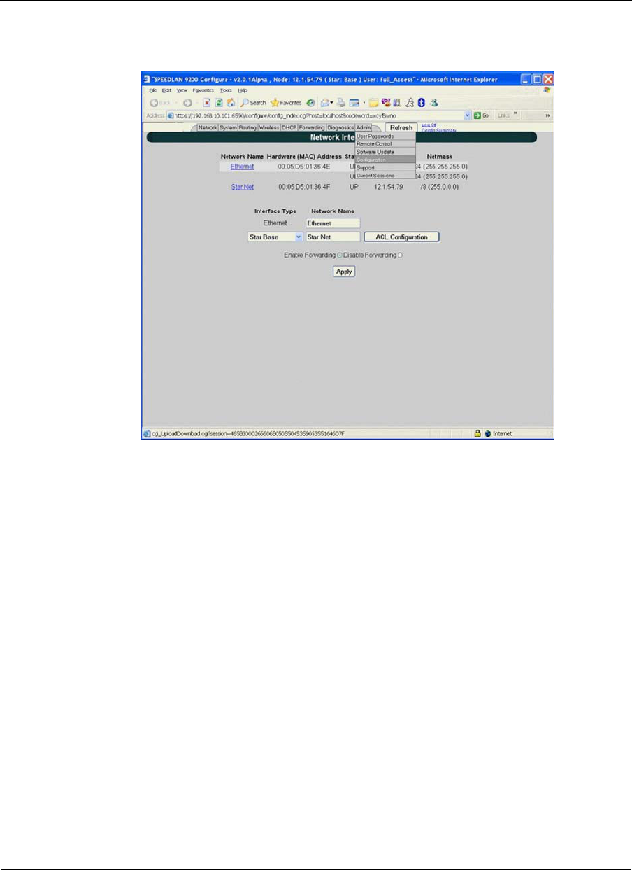
SPEEDLAN 9200 User Guide Part # 34357-MNL Rev. B
3-89
Figure 3-63: Configuration
CONFIGURATION DOWNLOAD
"Download Configuration File" button is used to activate the configuration download
process. When the download process is done, the configuration is saved in
c:\SL9200\phase2\SPEEDLANConf.ecf on the local host. The saved file is encrypted;
user is not able to read the contents; however, user can upload the same file to a
replacement unit or new unit later.
CONFIGURATION UPLOAD
"Upload Configuration File" button is used to activate the configuration upload process.
There are two steps in the upload process: 1) upload the specified configuration file, and
2) install the configuration file to the unit. After the configuration file is installed into the
unit, user can use the Web Configurator to configure the configurations parameters as
needed.
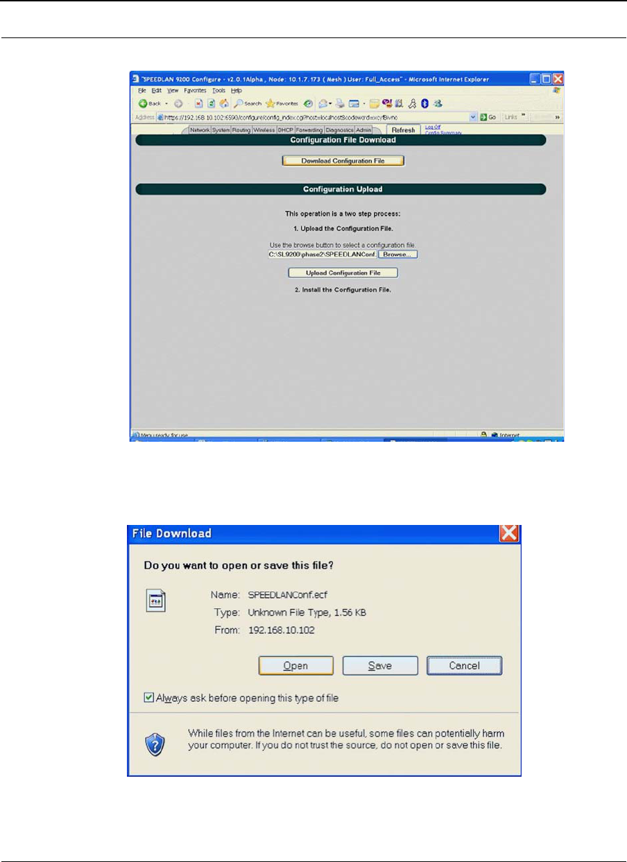
Part # 34357-MNL Rev. B SPEEDLAN 9200 User Guide
3-90
Figure 3-64: Configuration Download/Upload
Figure 3-65: Configuration Download
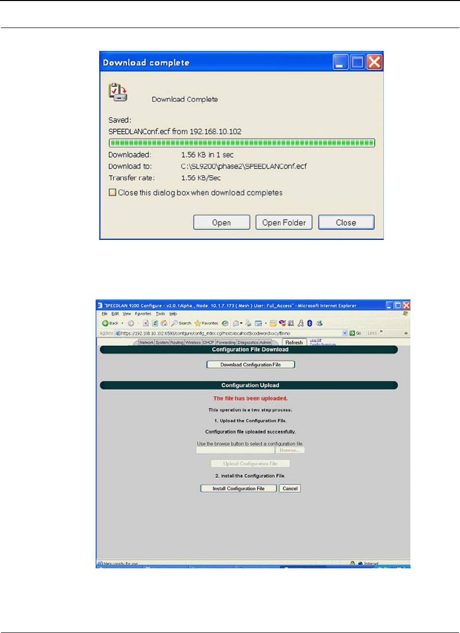
SPEEDLAN 9200 User Guide Part # 34357-MNL Rev. B
3-91
Figure 3-66: Download Complete
Figure 3-67: Upload Successful

Part # 34357-MNL Rev. B SPEEDLAN 9200 User Guide
3-92
Notes:_____________________________________________
__________________________________________________
__________________________________________________
__________________________________________________
__________________________________________________
__________________________________________________
__________________________________________________
__________________________________________________
__________________________________________________
__________________________________________________
__________________________________________________
__________________________________________________
__________________________________________________
__________________________________________________
__________________________________________________
__________________________________________________
__________________________________________________
__________________________________________________
__________________________________________________
__________________________________________________
__________________________________________________
__________________________________________________
__________________________________________________
__________________________________________________
__________________________________________________
__________________________________________________
__________________________________________________
__________________________________________________
__________________________________________________
__________________________________________________
__________________________________________________

Chapter 4
Using the Configurator to
Set Up Special Parameters
for Mesh Routers
This chapter covers only those special parameters needed to set
up mesh routers, such as:
•Network menu: Interfaces for Mesh Mode, page 4-2;
Mesh Nodes, page 4-3; Enabling/Disabling the SPEED-
Mesh-Enabled Client, page 4-3
•Wireless menu: Request to Send (RTS) / Clear to Send
(CTS), page 4-5; Receive (Rx) Threshold Parameter,
page 4-6, Blocked Links, page 4-8 and Link Expiration,
page 4-9. To set up other wireless configuration parame-
ters, see Configuration, Chapter 3
•Admin menu: Remote Control, page 4-10; Software
Update, page 4-10; and Updating the Software on a
Local Router and Remote Router(s), page 4-12
For other common configuration, see Overview of the
SPEEDLAN 9200 Configurator General Main Menu, Chapter 3.
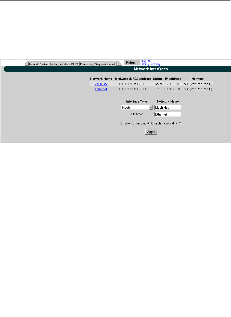
Part # 34357-MNL Rev. B SPEEDLAN 9200 User Guide
4-2
Network Menu
Interfaces for Mesh Mode
The Network Interfaces page will appear when you choose Interfaces under the Network
menu. This is where you enter the interface type and network name of the mesh interface.
Figure 4-1: Selecting mesh mode
•Network Name: This is the name you assign to the mesh interface.
•Hardware Address: In a LAN environment each network interface contains its
own Medium Access Control (MAC) address which is the embedded and unique
hardware number.
•Status: This is the state of the interface. Up - ready to pass packets; Down - can-
not pass packets.
•IP Address: This address tells the network how to locate the computers or
network equipment connected to it.
•Netmask: The netmask is a 4-byte number that masks the network part of the
Internet Protocol IP address, so only the host computer part of the address
remains.
•Interface Type: Select Mesh from the Interface Type drop-down list. When fin-
ished, click Apply. This will tell the configurator that you are in mesh mode.
•Network Name: The type of network for the wireless or fixed router.
•Enable Forwarding: Select the Enable Forwarding option to enable the
forwarding of IP packets from the wired interface to the wireless interface and
vice-versa.
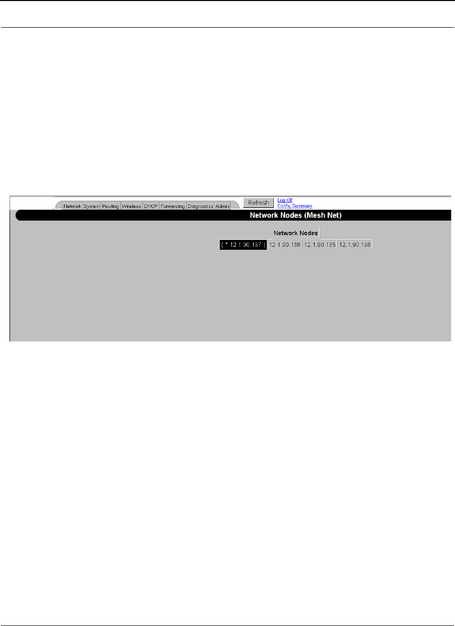
SPEEDLAN 9200 User Guide Part # 34357-MNL Rev. B
4-3
•Disable Forwarding: Select the Disable Forwarding option to disable the for-
warding of IP packets from the wired interface to the wireless interface and vice-
versa.
•Apply: Click after making changes.
Mesh Nodes
The Mesh Nodes (Network Nodes) page shows you what other routers are currently in
your network. This is useful if you do not have SPEEDView on your workstation. This
page will appear when you choose Mesh Nodes under the Network menu.
Figure 4-2: Network Nodes page
Enabling/Disabling the SPEEDMesh-Enabled Client
SPEEDLAN 9200 routers allow any 802.11 SPEEDMesh-enabled client (i.e., PC, PDA,
laptop) to join the wireless network. Network administrators can control access via WEP.
To enable or disable the SPEEDMesh client, do the following:
1Choose Mobile Client from the Network menu. The Mobile Client page will
appear:
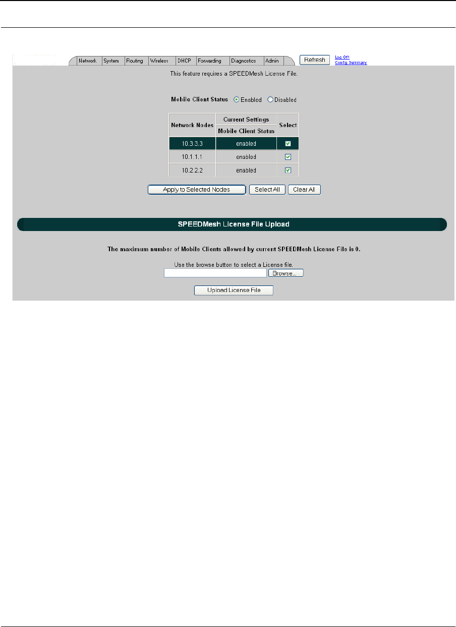
Part # 34357-MNL Rev. B SPEEDLAN 9200 User Guide
4-4
Figure 4-3: Enabling/disabling the SPEEDMesh client
2To enable the SPEEDMesh client, select the Enable Mobile Client check box.
3Select the nodes you want to enable for SPEEDMesh-enabled client mode node
via one node, all nodes (via Select All) or unselect all nodes (via Clear All).
4Click Apply to Selected Nodes to active the SPEEDMesh client(s).
5License Control: Enabling Mesh Client will not be enough if you want your
mobile clients to roam on the SPEEDLan MESH network. The administrator will
need to upload a SPEEDMesh License file. The SPEEDMesh License file speci-
fies the number of clients the Mesh router will allow at all times. The client will
need to enable the SPEEDMesh application to be able to roam around on the
SPEEDLan network. Otherwise the client will be limited to only that particular
SPEEDLan MESH router. Additional information can be obtained from the
SPEEDMesh User Guide, which is provided on your SPEEDManage CD.
Note: If you forgot to enable WEP security, see B. Enabling WEP Security Between a
SPEEDMesh-Enabled Client and SPEEDLAN 9200, page 4-5.