Wave Wireless SL9200 2.4, 5.8 & 4.9GHz (PSB) Wireless Router User Manual 34357 MNL Rev B
Wave Wireless Corporation 2.4, 5.8 & 4.9GHz (PSB) Wireless Router 34357 MNL Rev B
Contents
Users Manual 2

SPEEDLAN 9200 User Guide Part # 34357-MNL Rev. B
4-5
Wireless menu
Choose one of the options from the Wireless menu:
•If you choose Configuration, you will be able to set the following radio parame-
ters: SSID, wireless mode, channel, signaling rate, turbo mode, Tx power and
preamble. For more information, see Configuration, page 3-44 for more details.
•If you choose Tx Retries, you will be able to set the Transmit Retry Limit and Sig-
naling Rate Fallback. For more information, see Max Tx Retries and Signaling
Rate Fallback, Chapter 3.
•If you choose Max Throughput, you will be able to set the Max Transmit Data
Rate in Kb/s. For more information, see Max Throughput (Regulating Band-
width), Chapter 3.
•If you choose RTS/CTS and enable RTS/CTS for a particular node, it will refrain
from sending a unicast data frame until the node completes the "RTS/CTS hand-
shake" with the receiving node. For more information, see Request to Send (RTS)
/ Clear to Send (CTS), page 4-5.
•If you choose Rx Threshold, you will be able to set the threshold for each mesh
router on the network. For more information, see Receive (Rx) Threshold Param-
eter, page 4-6 for details.
•If you choose Blocked Links, you will be able to block or unblock mesh routers.
For more information, see Blocked Links, page 4-8 for more details.
•If you want to enter the number of times that a neighbor node can fail to reply to
a neighbor discovery probe before it is declared unreachable, see
Link Expiration, page 4-9.
Request to Send (RTS) / Clear to Send (CTS)
RTS/CTS allows you to fine-tune the operation of your wireless LAN. RTS/CTS will help
minimize collisions between transmissions from hidden nodes on the wireless network.
When you enable RTS/CTS for a particular node, it will refrain from sending a unicast
data frame until the node completes the "RTS/CTS handshake" with the receiving node.
Here is how the process works:
Node A transmits a RTS frame. Node B, on the receiving end, retrieves the RTS and sends
a response with a CTS frame. Before Node A sends the data frame, it must receive a CTS
frame from Node B. Both the RTS and CTS frames contain the length of the data frame to
Part # 34357-MNL Rev. B SPEEDLAN 9200 User Guide
4-6
alert other nodes to wait to access the network, while the node initiating the RTS sends its
data.
To enable RTS/CTS, choose RTS/CTS from the Wireless menu. The following screen will
appear.
Figure 4-4: RTS/CTS
•To turn on RTS/CTS, click the Enabled option.
•To turn off RTS/CTS, click the Disabled option.
•Threshold: The minimum size (in bytes) of unicast data frames whose
transmission will be preceded by a RTS/CTS handshake. The effective range is 50
through 1500. The optimal value depends on many factors, but a starting value of
100 is recommended. (The factors include the number of hidden nodes, the statis-
tical distribution of frame lengths, and the amount of
retransmissions caused by RF interference.)
•Select those nodes for which you want to enable RTS/CTS and click the Apply to
Selected Nodes button.
Receive (Rx) Threshold Parameter
From a single mesh unit connected to a mesh network, you can set the receive threshold
(given in dBm), for every mesh router in the network. The receive threshold specifies the
minimum acceptable receive level for a datagram (defined for signaling rates, depending
on the Wireless Mode you selected on the Wireless Configuration page). Any datagrams
SPEEDLAN 9200 User Guide Part # 34357-MNL Rev. B
4-7
received below these levels will be discarded. This will provide better network stability for
networks containing marginal links, since link state changes (and the corresponding
routing changes) will be avoided for marginal links which are not capable of consistent
communication.
By clicking the Defaults button, the values will go to their default values. If you enter a
value of 0 (zero), you are turning the receive threshold parameter off.
Figure 4-5: Rx Threshold page
The current Rx thresholds for your wireless mesh router(s) are listed in the Current Rx
Thresholds section. Their signaling rates are also listed, as described above.
If you click Default, it will load the current default setting for the Configurator. Click
Apply when finished.
Part # 34357-MNL Rev. B SPEEDLAN 9200 User Guide
4-8
Blocked Links
Figure 4-6: Blocking Mesh Routers
This feature allows you to block all traffic from a specific hardware address. This is most
often used when a marginal signal exists between two nodes in a mesh network, such that
the network functions more reliably when no direct communication occurs between the
nodes. To completely block a link you must perform the same action on the remote node.
Note: If you blocked a mesh Link, the next time it is rebooted it will remain blocked. If you
want to unblock the Link, make sure that the Blocked check box is not selected.
Note: Click Apply when finished.
Select the checkbox
under Blocked to block
a Link. Leave it unselected
when you want to leave
the Mesh Link unblocked.
SPEEDLAN 9200 User Guide Part # 34357-MNL Rev. B
4-9
Link Expiration
This page is only available for mesh routers.
To use this feature, choose Link Expiration from the Wireless menu. The following page
will appear:
Figure 4-7: Link Expiration
Neighbor Expiration Threshold: The number of consecutive missed neighbor discovery
probes that cause the direct link formed by two neighbors to be declared unusable. If bi-
directional traffic becomes possible in the future, the link will again become eligible for
use. The range for this parameter is 3-15. The default is 7.
After selecting a value for the parameter described above, select the nodes to which this
value will be sent (via the Select All or Apply to Selected Nodes buttons).
Then, click Apply.
Part # 34357-MNL Rev. B SPEEDLAN 9200 User Guide
4-10
Admin Menu
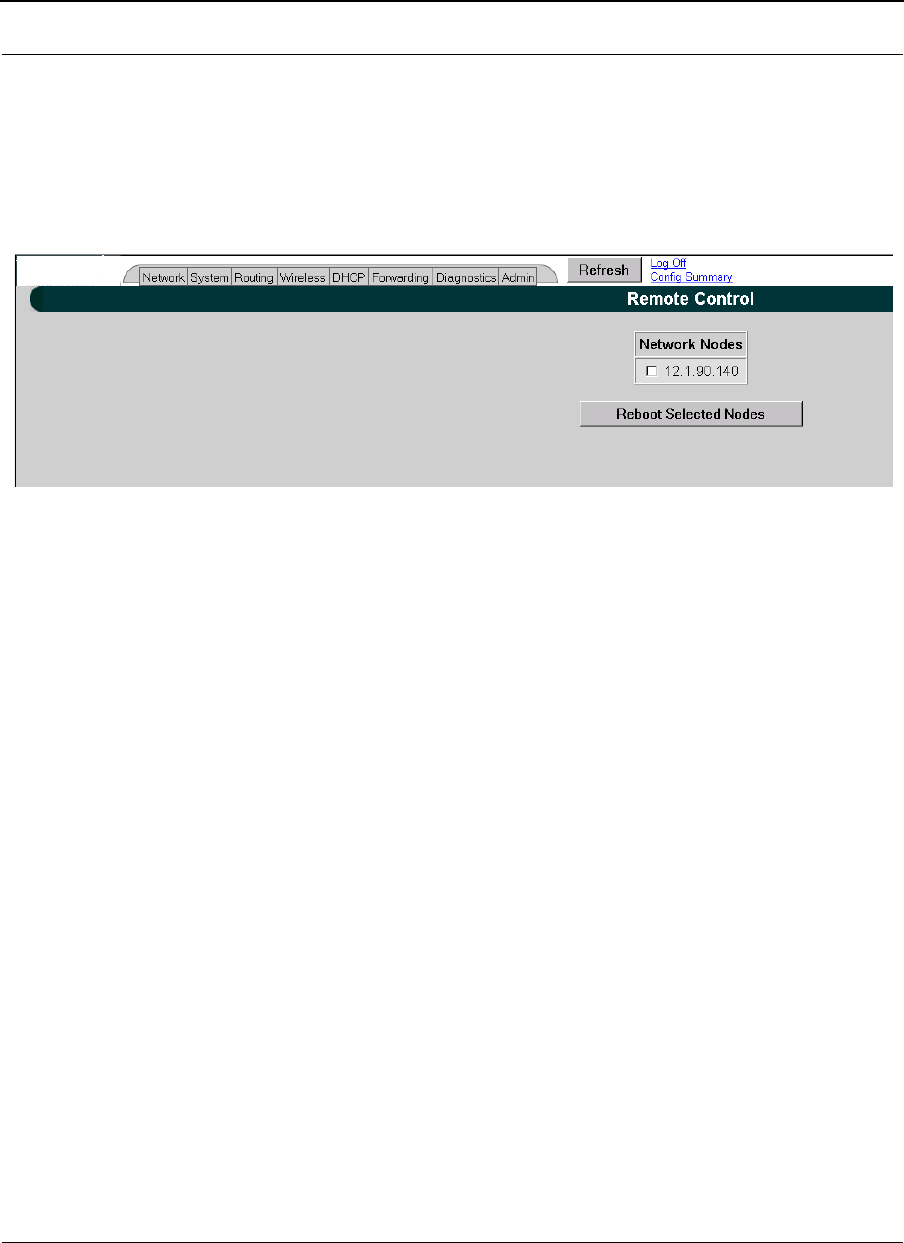
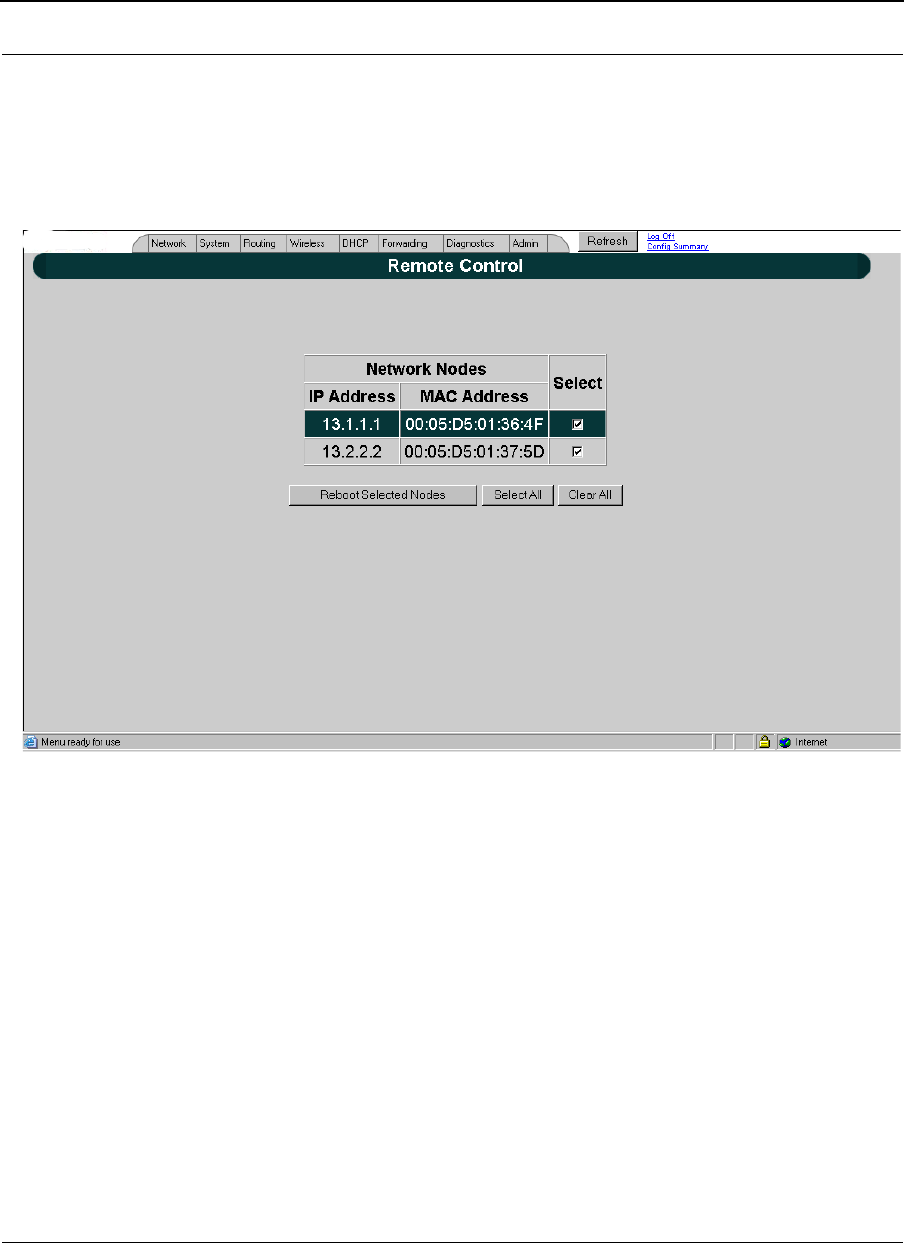
Remote Control
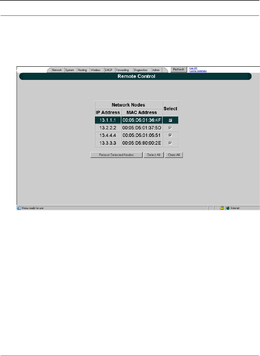
To remotely reboot or turn off the SPEEDLAN 9200 mesh routers, choose Remote Control
from the Admin menu. The following page will appear.
Figure 4-8: Remote Control for mesh mode
Select the mesh routers you want to reboot and click Reboot Selected Nodes. If there are
remote nodes, select them and click Select All or Clear All.
Software Update
Note: The Software Update zip file (found on www.wavewireless.com > click on Products
> SPEEDLAN 9200 > SPEEDLAN 9200 Download) will contain a document describing
the recent changes and any other additional information needed to perform the update.
The zip file will also include the update (.wwn) file to perform the update. After you have
unzipped the file, make sure you extract the update file (.wwn) file to your desktop. Then,
follow the directions below.
To update the software on the local router and/or on remote mesh routers, choose
Software Update from the Admin menu. The Software Update page will appear.
SPEEDLAN 9200 User Guide Part # 34357-MNL Rev. B
4-11
Updating the Local Router
If you only need to update the software on a local router, choose Local (under the
Software Update submenu).
Figure 4-9: Updating the software for mesh local router
This operation is a two-step process:
1Upload the Software Update file. Locate the latest software file (by clicking
Browse) and click Upload Software Update File.
2Install the Software Update.
Note: All units are automatically rebooted after a successful upgrade.
Part # 34357-MNL Rev. B SPEEDLAN 9200 User Guide
4-12
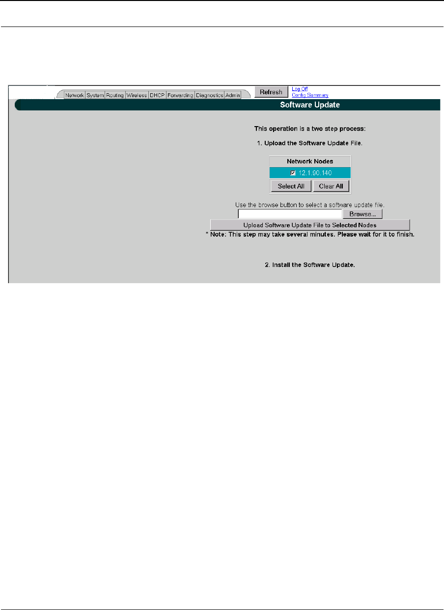
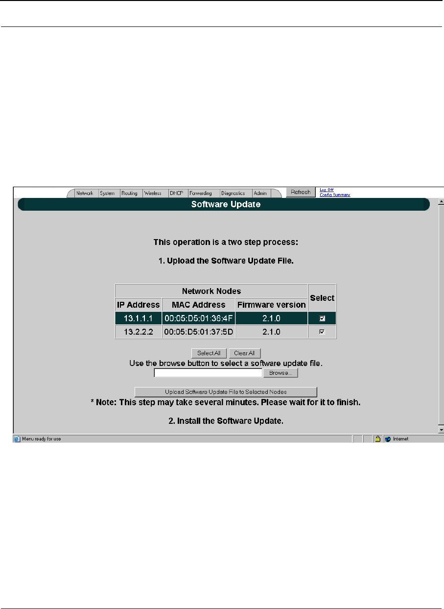
Updating the Software on a Local Router and Remote Router(s)
To update the software on a location router and on a remote router, choose it under the
Software Update submenu (e.g., MeshNet).
Figure 4-10: Updating the software for a local mesh and remote router
This operation is a two-step process:
1Select the remotes where you want to update the software. (The IP addresses that
are selectable are active. If only a MAC address is listed, or a bunch of zeros,
then these represent inactive devices.
2Upload the Software Update file. Locate the latest software file (by clicking
Browse) and click Upload Software Update File to Selected Nodes.
3Install the Software Update.

SPEEDLAN 9200 User Guide Part # 34357-MNL Rev. B
4-13
Notes:_____________________________________________
__________________________________________________
__________________________________________________
__________________________________________________
__________________________________________________
__________________________________________________
__________________________________________________
__________________________________________________
__________________________________________________
__________________________________________________
__________________________________________________
__________________________________________________
__________________________________________________
__________________________________________________
__________________________________________________
__________________________________________________
__________________________________________________
__________________________________________________
__________________________________________________
__________________________________________________
__________________________________________________
__________________________________________________
__________________________________________________
__________________________________________________
__________________________________________________
__________________________________________________
__________________________________________________
__________________________________________________
__________________________________________________
__________________________________________________
__________________________________________________

Part # 34357-MNL Rev. B SPEEDLAN 9200 User Guide
4-14

Chapter 5
Using the Configurator to
Set Up Special Parameters
for a Star Base Station
This chapter covers only those special parameters needed to set
up a base station, such as:
•Network menu: Interfaces for Base Mode, page 5-2;
Access Control List (ACL) ;Per CPE Settings, Page 5-4
•Admin menu: Updating the Software on a Base Station
and CPE, page 5-6
For other common configuration, see Overview of the
SPEEDLAN 9200 Configurator General Main Menu, Chapter 3.
Part # 34357-MNL Rev. B SPEEDLAN 9200 User Guide
5-2
Network Menu
•To enter the interface (router) type and network name of the interface(s), choose
Interfaces from the Network menu.
•To define what CPE routers are participating in the network, choose ACL Con-
figuration
from the Network menu. and If you clicked Per CPE Settings Button..., page 5-8.
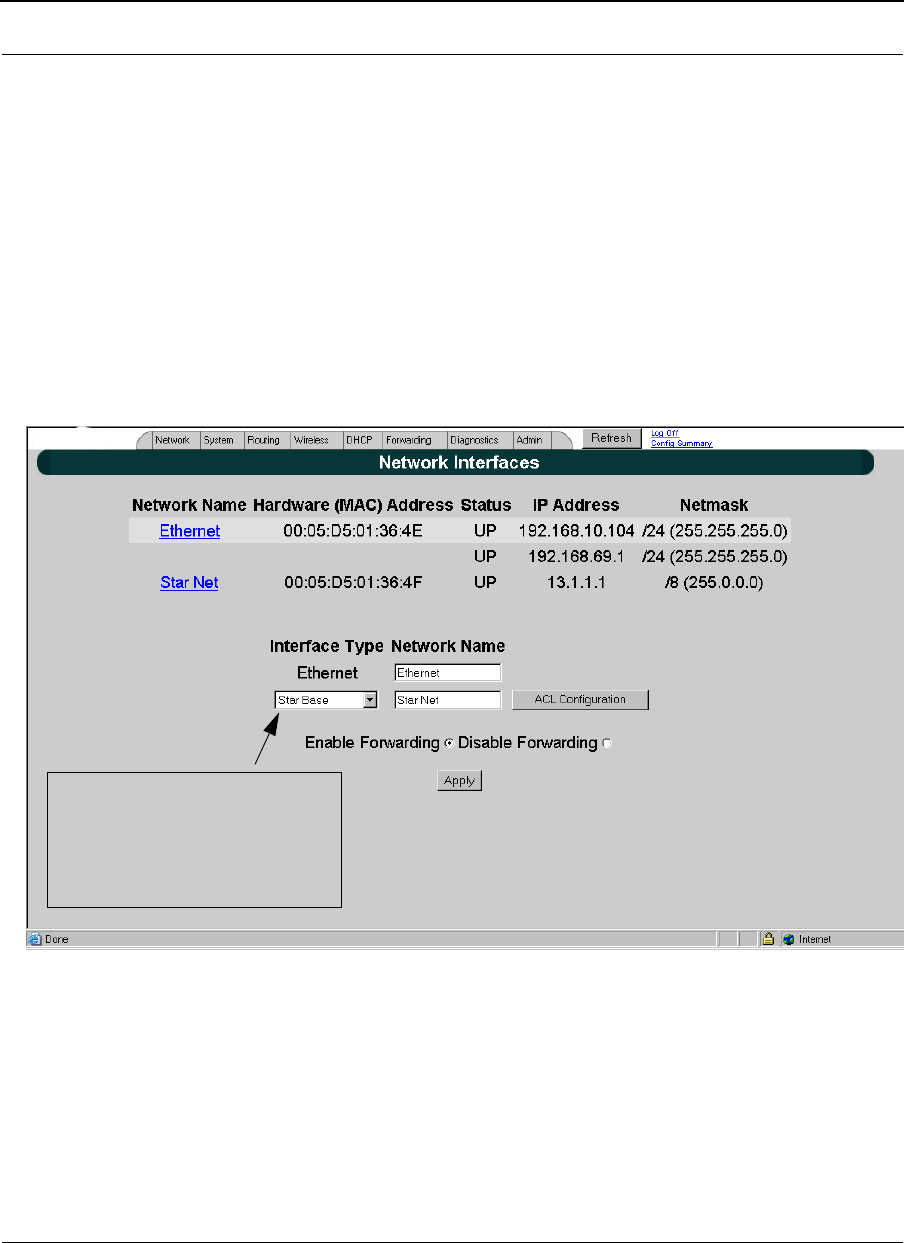
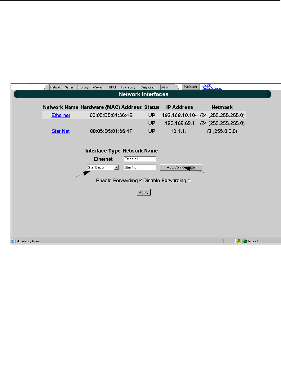
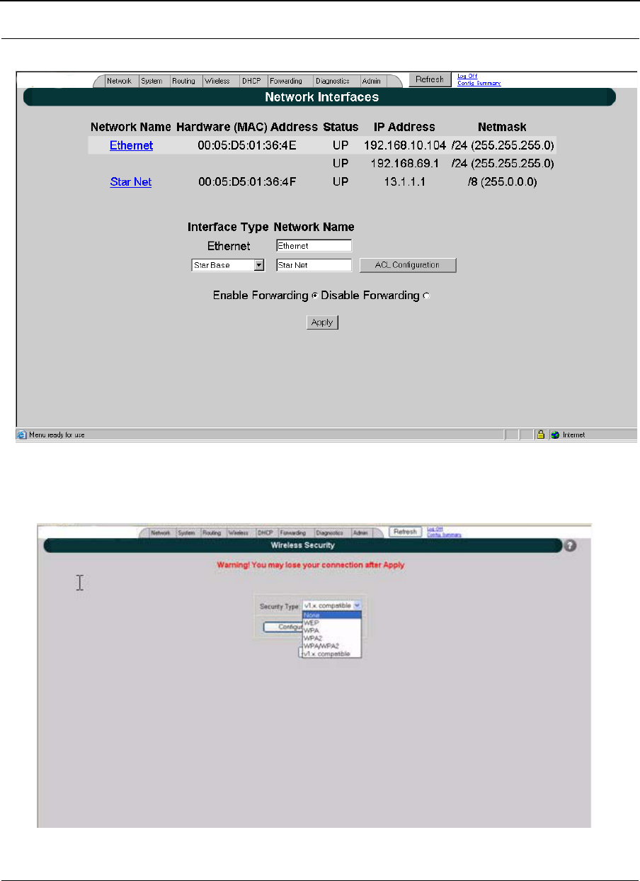
Interfaces for Base Mode
The Network Interfaces page will appear when you choose Interfaces under the Network
menu. This is where you enter the interface type and network name of the interface or the
router.
Figure 5-1: Selecting base station mode
•Network Name: This is the fixed or wireless interface (e.g., base station).
•Hardware Address: In a LAN environment each network interface contains its
own Medium Access Control (MAC) address which is the embedded and unique
hardware number.
Select the Base Station from
the Interface Type drop-down
list. When finished, Click Apply.
This will tell the configurator that
you are in the Base Station mode.
SPEEDLAN 9200 User Guide Part # 34357-MNL Rev. B
5-3
•Status: This is the state of the interface. Up - ready to pass packets; Down - can-
not pass packets.
•IP Address: This address tells the network how to locate the computers or
network equipment connected to it.
•Netmask: The netmask is a 4-byte number that masks the network part of the
Internet Protocol IP address, so only the host computer part of the address
remains.
•Interface Type: Select the interface (e.g., base station) from this drop-down list.
(This will tell the configurator that you are in base station mode.)
•Network Name: The type of network for the wireless or fixed router.
•Enable Forwarding: Select the Enable Forwarding option to enable the
forwarding of IP packets from the wired interface to the wireless interface and
vice-versa.
•Disable Forwarding: Select the Disable Forwarding option to disable the for-
warding of IP packets from the wired interface to the wireless interface and vice-
versa.
•Apply: Click after making changes.
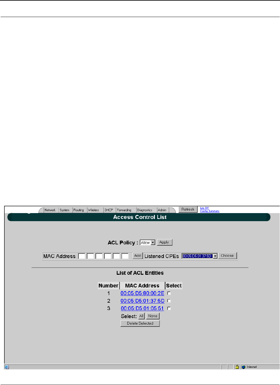
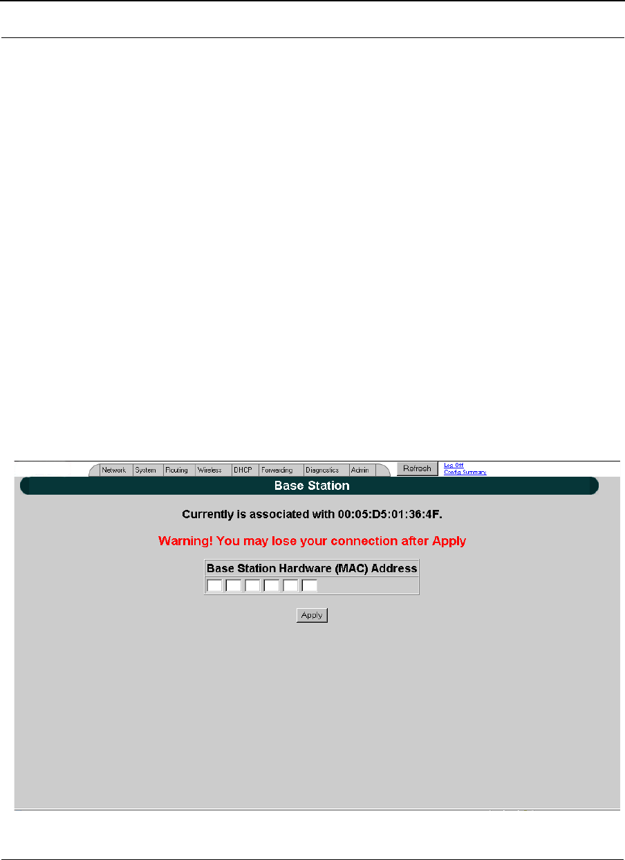
•ACL Configuration: Click to define what CPE routers are participating in the
star network. When you click this button, a new page will appear as follows:
Part # 34357-MNL Rev. B SPEEDLAN 9200 User Guide
5-4
Figure 5-2: Access Control List
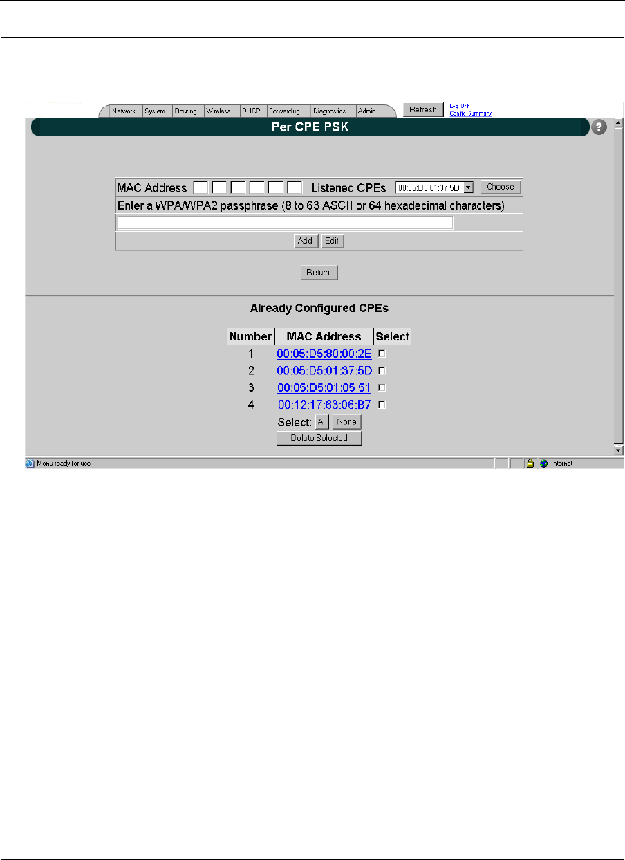
Per CPE Settings
Figure 5-3: Per CPE Settings page
1On the top half of the page: You have to authenticate an IP address for each CPE
so it is listed in the routing table. To do this, enter the hardware address of the
CPE in the Hardware (MAC) Address text box. The IP addresses will not be
active until the user logs on the particular CPE router.
2Click Edit to change an existing pass phrase that was set for a given CPE. Click
Add if the pass phrase has not been set for a given CPE.
Note: You can configure a base station router on this page if you delete the existing one by
clicking Delete.
Other elements on the Per CPE Settings page:
•Delete: Click to remove the hardware address.
SPEEDLAN 9200 User Guide Part # 34357-MNL Rev. B
5-5
Admin Menu
Remote Control
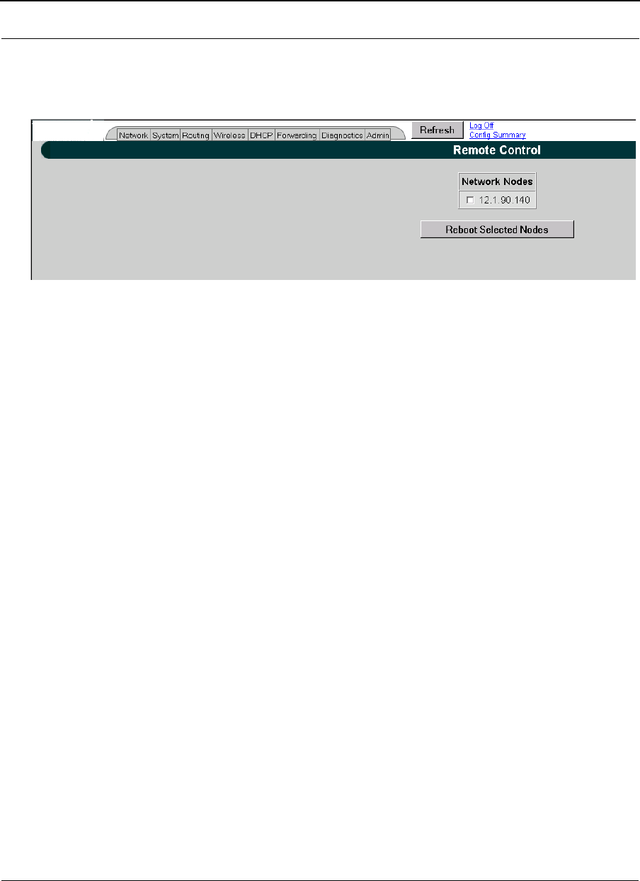
To remotely reboot or turn off the SPEEDLAN 9200 base stations, choose Remote Control
from the Admin menu. The following page will appear.
Figure 5-4: Remote Control for base mode
Select the base stations you want to reboot and click Reboot Selected Nodes.
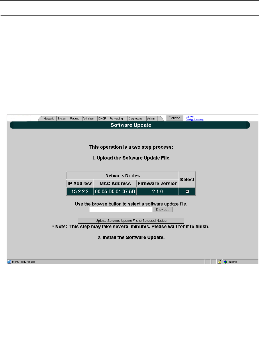
Software Update
To update the software on the local base station or on the remotes (e.g., CPE, Ethernet,
etc.), choose Software Update from the Admin menu. The Software Update page will
appear (for Local or Star Net). Note: The Software Update zip file (found on
www.wavewireless.com/support + Firmware link) will contain a document describing the
recent changes and any other additional information needed to perform the update. The
zip file will also include the update (.wwn) file to perform the update. After you have
unzipped the file, make sure you extract the update file (.wwn) file to your desktop. Then,
follow these directions:
Part # 34357-MNL Rev. B SPEEDLAN 9200 User Guide
5-6
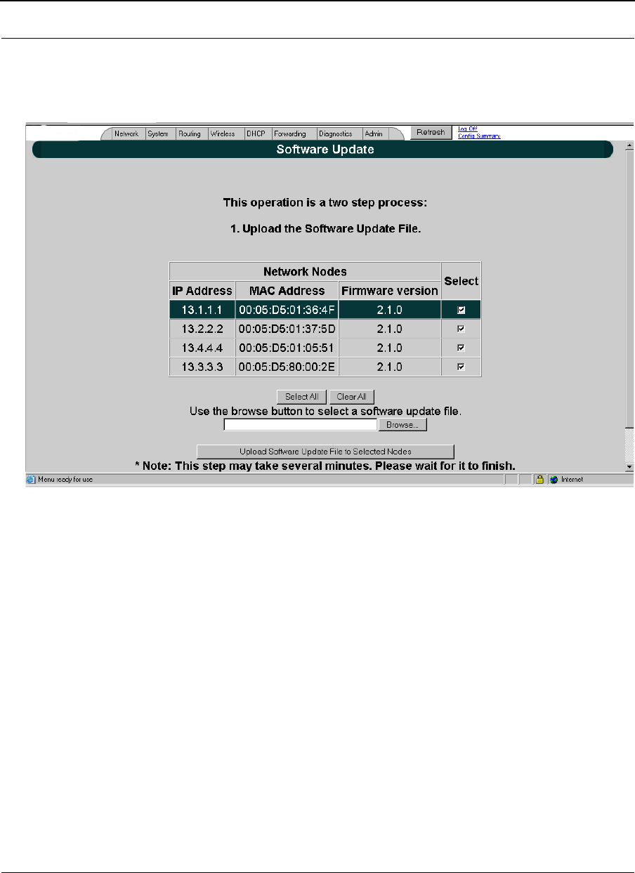
Updating the Software on a Base Station and CPE
To update the software on a base station and on a CPE, choose Software Update from
Admin tab
Figure 5-5: Updating software on a base station and CPE
This operation is a two-step process:
1Select the remotes (CPE routers) where you want to update the software. (The IP
addresses that are selectable are active. If only a MAC address is listed, or a
bunch of zeros, then these represent inactive devices.
2Upload the Software Update file. Locate the latest software file (by clicking
Browse) and click Upload Software Update File to Selected Nodes.
3Install the Software Update. Note: When you updated your network in the past,
the remotes would not be rebooted until the final step. This step
happened after you clicked the Reboot Updated Nodes button. Now the remotes
are automatically rebooted after a successful upgrade. The local or connected
router is not rebooted until you click the Reboot Updated Nodes button at the end
of the upgrade.
IP address
Host name
MAC address
Firmware version

SPEEDLAN 9200 User Guide Part # 34357-MNL Rev. B
5-7
Notes:_____________________________________________
__________________________________________________
__________________________________________________
__________________________________________________
__________________________________________________
__________________________________________________
__________________________________________________
__________________________________________________
__________________________________________________
__________________________________________________
__________________________________________________
__________________________________________________
__________________________________________________
__________________________________________________
__________________________________________________
__________________________________________________
__________________________________________________
__________________________________________________
__________________________________________________
__________________________________________________
__________________________________________________
__________________________________________________
__________________________________________________
__________________________________________________
__________________________________________________
__________________________________________________
__________________________________________________
__________________________________________________
__________________________________________________
__________________________________________________
__________________________________________________

Part # 34357-MNL Rev. B SPEEDLAN 9200 User Guide
5-8

Chapter 6
Using the Configurator to
Set Up Special Parameters
for CPE Routers
This chapter covers only those special parameters needed to set
up the Customer Premise Equipment (CPE), such as:
•Network menu: Interfaces for CPE Mode, page 6-2;
Base Station Information, page 6-3
•Admin menu: Software Update, page 6-4
For other common configuration, see Overview of the
SPEEDLAN 9200 Configurator General Main Menu, Chapter 3.
Part # 34357-MNL Rev. B SPEEDLAN 9200 User Guide
6-2
Network Menu
Interfaces for CPE Mode
The Network Interfaces page will appear when you choose Interfaces under the Network
menu. This is where you enter the interface type and network name of the interface or the
router.
Figure 6-1: Selecting CPE mode
•Network Name: This is the fixed or wireless interface (e.g., CPE).
•Hardware Address: In a LAN environment each network interface contains its
own Medium Access Control (MAC) address which is the embedded and unique
hardware number.
•Status: This is the state of the interface. Up - ready to pass packets; Down - can-
not pass packets.
•IP Address: This address tells the network how to locate the computers or
network equipment connected to it.
This is the network name of
the type of interface.
Select the CPE from the
Interface Type drop-down list.
When finished, click Apply.
This will tell the
configurator that you are in
CPE mode.
SPEEDLAN 9200 User Guide Part # 34357-MNL Rev. B
6-3
•Netmask: The netmask is a 4-byte number that masks the network part of the
Internet Protocol IP address, so only the host computer part of the address
remains.
•Interface Type: Select the CPE from the Interface Type drop-down list. When fin-
ished, click Apply. This will tell the configurator that you are in CPE mode.
•Network Name: The type of network for the wireless or fixed router.
•Enable Forwarding: Select the Enable Forwarding option to enable the
forwarding of IP packets from the wired interface to the wireless interface and
vice-versa.
•Disable Forwarding: Select the Disable Forwarding option to disable the for-
warding of IP packets from the wired interface to the wireless interface and vice-
versa.
•Apply: Click after making changes.
Base Station Information
To see if a CPE is connected to the base station, choose Base Station Info from the
Network menu. The following page will appear. Note: If there is no connection to the base
station, a message will appear confirming that the CPE is not connected to the base
station.
Figure 6-2: Base Station Information (for CPE mode)
Part # 34357-MNL Rev. B SPEEDLAN 9200 User Guide
6-4
Admin Menu
Software Update
Note: The Software Update zip file (found on www.wavewireless.com/support under the
Support + Firmware link) will contain a document describing the recent changes and any
other additional information needed to perform the update. The zip file will also include
the update (.wwn) file to perform the update. After you have unzipped the file, make sure
you extract the update file (.wwn) file to your desktop. Then, follow the directions below.
To update the software on a CPE, choose Software Update from the Admin menu. The
following page will appear.
Figure 6-3: Updating the software on the CPE
If you obtain a software update file from Wave Wireless Networking you can use this page
to update software on one or more SPEEDLAN 9200 routers.
This operation is a two-step process:
This operation is a two-step process:

SPEEDLAN 9200 User Guide Part # 34357-MNL Rev. B
6-5
1Upload the Software Update file. Locate the latest software file (by clicking
Browse) and click Upload Software Update File.
2Install the Software Update.
Note: All units are automatically rebooted after a successful upgrade.

Part # 34357-MNL Rev. B SPEEDLAN 9200 User Guide
6-6
Notes:_____________________________________________
__________________________________________________
__________________________________________________
__________________________________________________
__________________________________________________
__________________________________________________
__________________________________________________
__________________________________________________
__________________________________________________
__________________________________________________
__________________________________________________
__________________________________________________
__________________________________________________
__________________________________________________
__________________________________________________
__________________________________________________
__________________________________________________
__________________________________________________
__________________________________________________
__________________________________________________
__________________________________________________
__________________________________________________
__________________________________________________
__________________________________________________
__________________________________________________
__________________________________________________
__________________________________________________
__________________________________________________
__________________________________________________
__________________________________________________

Chapter 7
Using the Configurator to
Set Up Special Parameters
for Point-to-Point Routers
This chapter covers only those special parameters needed to set
up the point-to-point primary and secondary routers, such as:
•Network menu: Interfaces for Point-to-Point Mode,
page 7-2; Point-to-Point Settings, page 7-3;
•Admin: Remote Control for Point-to-Point Primary
Routers, page 7-6; Software Update for Point-to-Point
Primary or Secondary Routers, page 7-6; and Updating
the Software on a Local Router and Remote Router: Pri-
mary Mode Only, page 7-7
For other common configuration, see Overview of the
SPEEDLAN 9200 Configurator General Main Menu, Chapter 3.
Part # 34357-MNL Rev. B SPEEDLAN 9200 User Guide
7-2
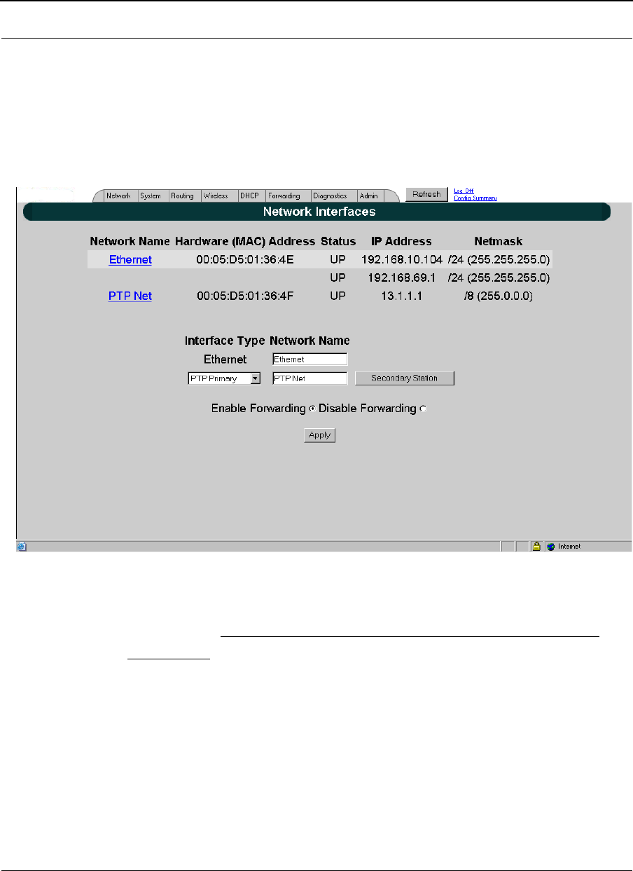
Network Menu
Interfaces for Point-to-Point Mode
The Network Interfaces page will appear when you choose Interfaces under the Network
menu. This is where you enter the interface type (or router) and network name of the
interface (or the point-to-point primary or secondary router).
Figure 7-1: Selecting point-to-point primary or secondary mode
Important Note: The "Pt to Pt Configure" button is only accessible in point-to-point
primary mode.
•Network Name: This is the fixed or wireless interface (e.g., pt to pt: primary or pt
to pt: secondary).
•Hardware Address: In a LAN environment each network interface contains its
own Medium Access Control (MAC) address which is the embedded and unique
hardware number.
•Status: This is the state of the interface. Up - ready to pass packets; Down - can-
not pass packets.

SPEEDLAN 9200 User Guide Part # 34357-MNL Rev. B
7-3
•IP Address: This address tells the network how to locate the computers or
network equipment connected to it.
•Netmask: The netmask is a 4-byte number that masks the network part of the
Internet Protocol IP address, so only the host computer part of the address
remains.
•Interface Type: Select the point to point router (primary or secondary) from the
Interface Type drop-down list. When finished, click Apply. This will tell the con-
figurator that you are in point to point (primary or secondary) mode.
•Network Name: The type of network for the wireless or fixed router.
•Enable Forwarding: Select the Enable Forwarding option to enable the
forwarding of IP packets from the wired interface to the wireless interface and
vice-versa.
•Disable Forwarding: Select the Disable Forwarding option to disable the for-
warding of IP packets from the wired interface to the wireless interface and vice-
versa.
•Apply: Click after making changes.
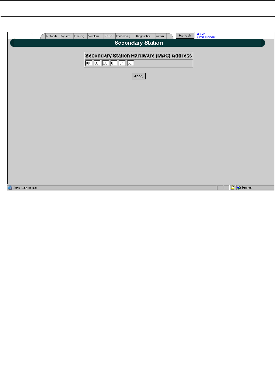
Point-to-Point Settings
To set up your point-to-point primary or secondary routers (that is, if you are in primary
mode), choose Secondary Station from the Network menu. The following default page will
appear. An alternative is to also click Secondary Station on the Network Interfaces page
Part # 34357-MNL Rev. B SPEEDLAN 9200 User Guide
7-4
.
Figure 7-2: Configuring Secondary Point-to-Point Settings (if in Primary mode)
SPEEDLAN 9200 User Guide Part # 34357-MNL Rev. B
7-5
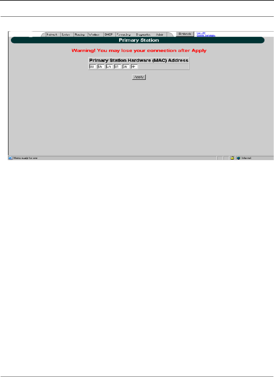
Figure 7-3: Configuring Primary Node Settings (in Secondary mode)
Activation Primary and Secondary Routers
•Activating Primary Router: Enter the PTP Net MAC address for the Secondary
router. This Number is given in the Network Interface screen of the Secondary
router. Then, clickApply to Activate selection
•Activating Secondary Router: Enter the PTP Net MAC address for the Primary
router. This Number is given in the Network Interface screen of the Primary
router.
•Then, click Apply to Activate selection
Part # 34357-MNL Rev. B SPEEDLAN 9200 User Guide
7-6
Admin Menu
Remote Control for Point-to-Point Primary Routers
To remotely reboot or turn off the SPEEDLAN 9200 point-to-point primary routers,
choose Remote Control from the Admin menu. The following page will appear.
Figure 7-4: Remote Control for point-to-point primary mode (in Primary mode)
Select the primary point-to-point routers you want to reboot and click Reboot Selected
Nodes.
All other common configuration information can be found in General Functions of the
Configurator, Chapter 3.
Software Update for Point-to-Point Primary or Secondary
Routers
Note: The Software Update zip file (found on www.wavewireless.com/support +
Firmware link) will contain a document describing the recent changes and any other
additional information needed to perform the update. The zip file will also include the
update (.wwn) file to perform the update.
SPEEDLAN 9200 User Guide Part # 34357-MNL Rev. B
7-7
After you have unzipped the file, make sure you extract the update file (.wwn) file to your
desktop. Then, follow the directions below.
To update the software on the local router or on the remote point-to-point routers, choose
Software Update from the Admin menu. The Software Update page will appear.
Updating the Software on a Local Router and Remote Router:
Primary Mode Only
To update the software on a location router and on a remote point-to-point primary
router, choose it under the Software Update submenu.
Figure 7-5: Updating the software for a point-to-point primary router (in Primary mode only)
This operation is a two-step process:
1Select the point-to-point routers where you want to update the software. (The IP
addresses that are selectable are active. If only a MAC address is listed, or a
bunch of zeros, then these represent inactive devices.
2Upload the Software Update file. Locate the latest software file (by clicking
Browse) and click Upload Software Update File to Selected Nodes.

Part # 34357-MNL Rev. B SPEEDLAN 9200 User Guide
7-8
3Install the Software Update. All other common configuration information can be
found in General Functions of the Configurator, Chapter 3.
Notes:_____________________________________________
__________________________________________________

SPEEDLAN 9200 User Guide Part # 34357-MNL Rev. B
7-9
__________________________________________________
__________________________________________________
__________________________________________________
__________________________________________________
__________________________________________________
__________________________________________________
__________________________________________________
__________________________________________________
__________________________________________________
__________________________________________________
__________________________________________________
__________________________________________________
__________________________________________________
__________________________________________________
__________________________________________________
__________________________________________________
__________________________________________________
__________________________________________________
__________________________________________________
__________________________________________________
__________________________________________________
__________________________________________________
__________________________________________________
__________________________________________________
__________________________________________________
__________________________________________________
__________________________________________________
__________________________________________________
__________________________________________________

Part # 34357-MNL Rev. B SPEEDLAN 9200 User Guide
7-10

Chapter 8
Configurating Security
Parameters
This chapter covers those parameters needed to set up Security
INTRODUCTION
Our previous 9200 products supported AES [advanced encryption
standard] encryption used a single static key for all links in the
mesh and all type of traffic over them. The new release adds
support to WPA with TKIP & MIC and WPA2 with AES-CCMP
which include a dynamic key management system. The new
design also allows "Per Group" encoding of unicast and multicast
packets as well as simultaneous and independent "Per Link"
encoding of unicast packets in each link in the network.
Wireless Security in SPEEDLAN 9200 units provide the following
types of security:
•WEP
•WPA
•WPA2 (RSN)
•WPA/WPA2

Part # 34357-MNL Rev. B SPEEDLAN 9200 User Guide
8-2
WPA and WPA2 are supported in SPEEDLAN Phase2 Release to provide the security for
SPEEDLAN units in Mesh, Star, and PTP Network Topologies.
WPA is a subset of the IEEE 802.11i specification. It replaces WEP with a strong new
encryption technology Temporal Key Integrity Protocol (TKIP) with Message Integrity
Check (MIC). It also provides a authentication scheme using either IEEE 802.1x or pre-
shared key (PSK) technology.
Like WPA, WPA2 supports IEEE 802.1x or PSK technology. It also includes a new
advanced encryption mechanism Advanced Encryption Standard (AES) using the
Counter-Mode/CBC-MAC Protocol (CCMP).
There are 2 modes of WPA and WPA2 certification - Enterprise and Personal. Table
below lists the authentication scheme and Encryption method used in each certification
mode.
WPA ad WPA2 Personal Mode certification is supported in SPEEDLAN 9200 Phase2 to
provide per-link, per-packet encryption via TKIP with WPA or AES with WPA2.
PSK Authentication
PSK based authentication is supported in all three Network Topologies - Mesh, Star and
Point to point (PTP). Using PSK authentication scheme, user configures a pre-shared key
on both supplicant and authenticator SPEEDLAN units. This pre-shared key is used as
the Pairwise Master Key (PMK) to derive four separate keys that will be used in
protecting the link between two SPEEDLAN units. The collection of all four keys together
is referred to as the pairwise transient key (PTK).
Table 1: Modes of Certification
WPA WPA2
Enterprise
Mode Authentication IEEE 802.1 X/EAP
Encryption: TKIP/MIC Authentication IEEE 802.1X/EAP
Encryption: AES-CCMP
Personal
Mode Authentication: PSK
Encryption: TKIP/MIC Authentication: PSK
Encryption: AES-CCMP

SPEEDLAN 9200 User Guide Part # 34357-MNL Rev. B
8-3
Table below lists the authenticator and supplicant in each Network Topology.
Cipher Suites and Key Management
Cipher suites are sets of encryption and integrity algorithms designed to protect radio
communication on wireless LAN, and they are:
•WEP (Wired Equivalent Privacy) - a 802.11 standard encryption algorithm orig-
inally designed to provide your wireless LAN with the same level of privacy
available on a wired LAN. However, the basic WEP construction is flawed, and
an attacker can compromise the privacy with reasonable effort.
•TKIP (Temporal Key Integrity Protocol) - a suite of algorithms surrounding
WEP that is designed to achieve the best possible security on legacy hardware
built to run WEP.
•CCMP (Counter Mode-CBC MAC) - an AES based cipher; which yields the high
level of data privacy required by some enterprises, government agencies and
other organizations. CCMP support is mandatory in both the 802.11i specifica-
tion and WPA2. Pre-authentication will be optional for both 802.11i and WPA2.
WPA replaces WEP with TKIP. WPA2 includes the advanced encryption mechanism AES
into the support.
SPEEDLAN unit uses the following cipher suites to protect unicast messages in Mesh,
Star, and PTP networks, and the multicast/broadcast messages in Star, and PTP
networks:
•CCMP;
•TKIP;
•WEP-64, WEP-128 and 156.
SPEEDLAN9200 unit uses the following cipher suites to protect multicast/broadcast
messages in Mesh network:
Table 2: PSK Authentication
Mesh Star Base Star CPE PTP
Primary PTP
Secondary
Authenticator XX X
Supplicant XXX

Part # 34357-MNL Rev. B SPEEDLAN 9200 User Guide
8-4
CCMP with Static key and hardware decryption (weak security, higher performance);
CCMP with software decryption (strong security, lower performance).
CONFIGURATIONS
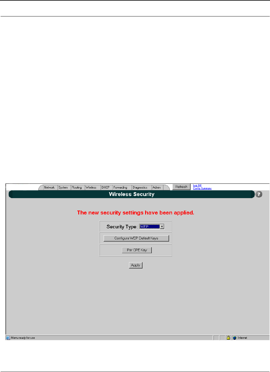
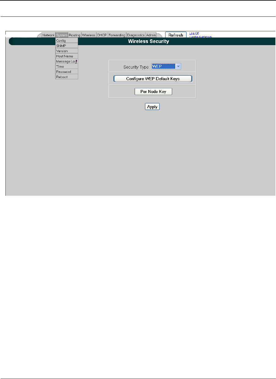
SPEEDLAN 9200 supports four security types - WEP, WPA, WPA2, and WPA/WPA2.
Table below lists the authentication scheme and Encryption method for each security
type:
WPA, WPA2, WPA/WPA2
Path to access the Security Page from Web Configurator is: Main Page->Network->
Security.
Table 3: Security Types for Authentication and Encryption
Authentication Encryption
WEP N/A WEP
WPA PSK TKIP
WPA2 PSK AES
WPA/WPA2 PSK TKIP or AES
SPEEDLAN 9200 User Guide Part # 34357-MNL Rev. B
8-5
Figure 8-1: Network Security-Interfaces
Figure 8-2: Network Security-Star Base Mode
Part # 34357-MNL Rev. B SPEEDLAN 9200 User Guide
8-6
This screen appears if "v1.x compatible" is selected from the above screen.
If one or more routers in your network is operating with Firmware version 1.0.8 or older,
then some security options are not available on the older routers. However, you can
select "v1.x compatible" from the drop-down menu titled Security Type on the Wireless
Security screen, which will allow the newer routers to operate with AES encryption, which
all older versions are already equipped with.
Please contact sales or customer service to request a Firmware upgrade for your routers
operating with an older Firmware version than is listed as the most current release in the
Fimware History section of this manual.
SPEEDLAN 9200 User Guide Part # 34357-MNL Rev. B
8-7
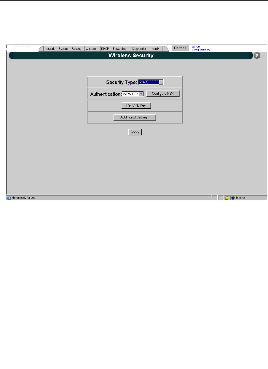
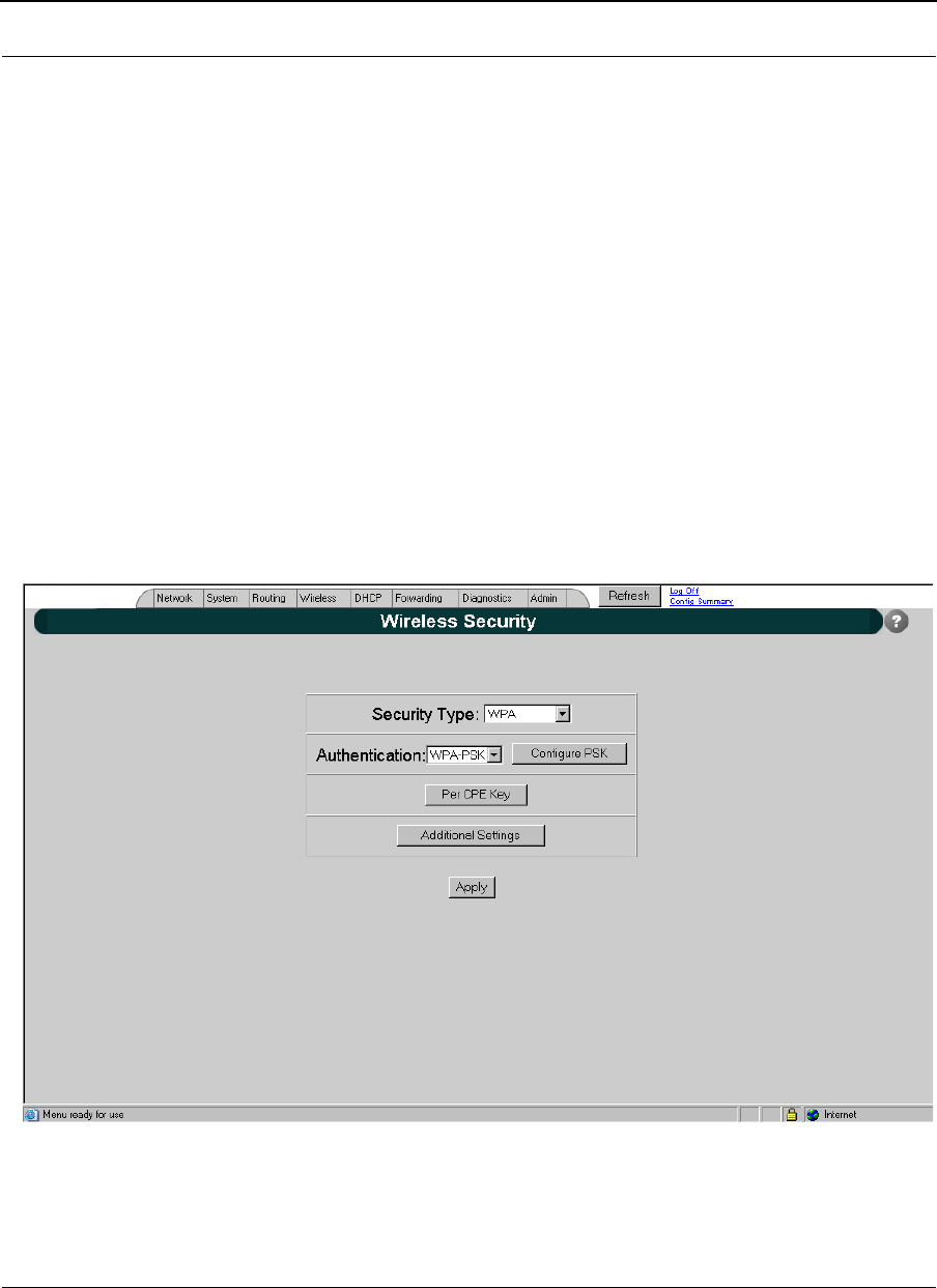
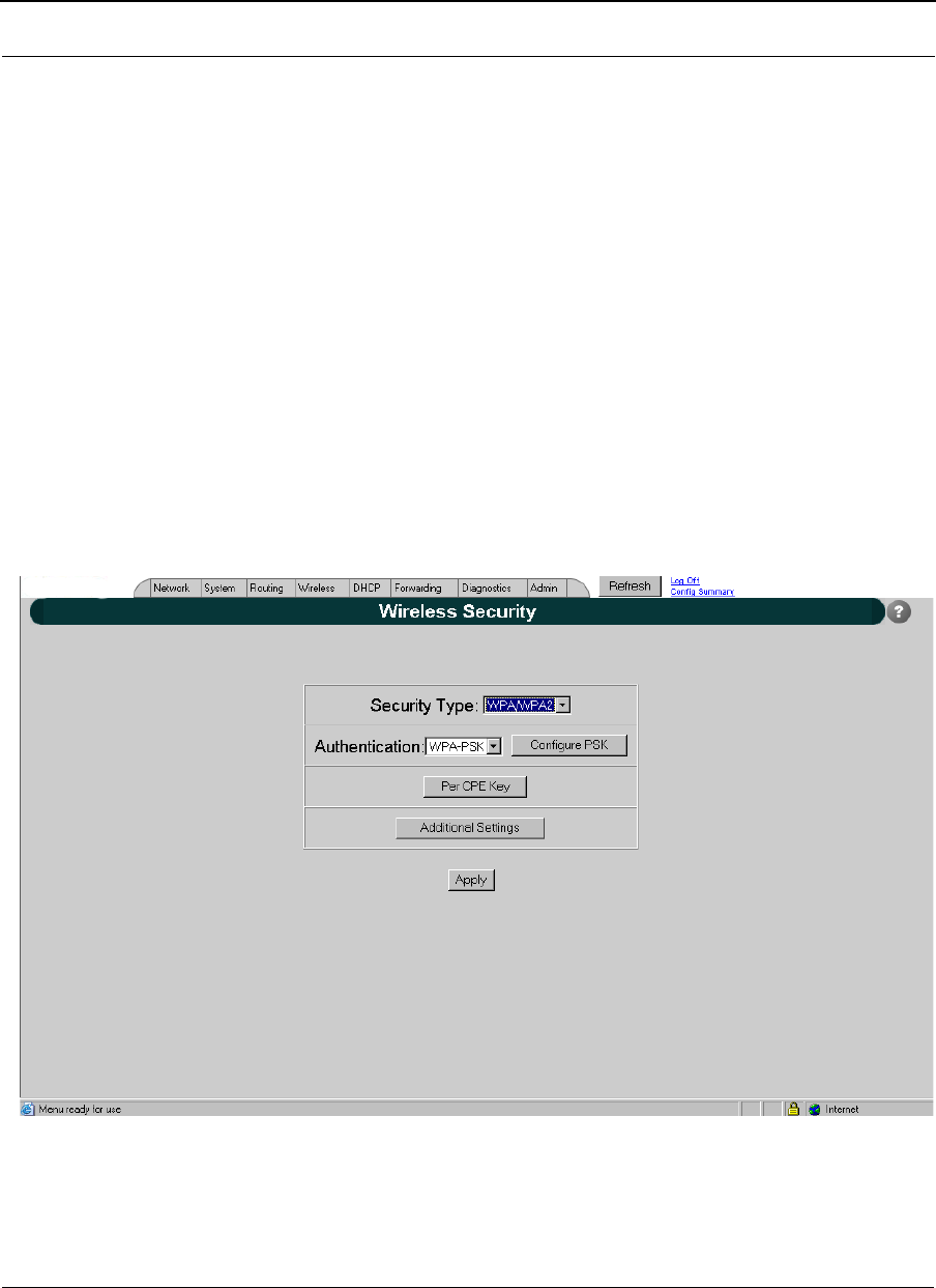
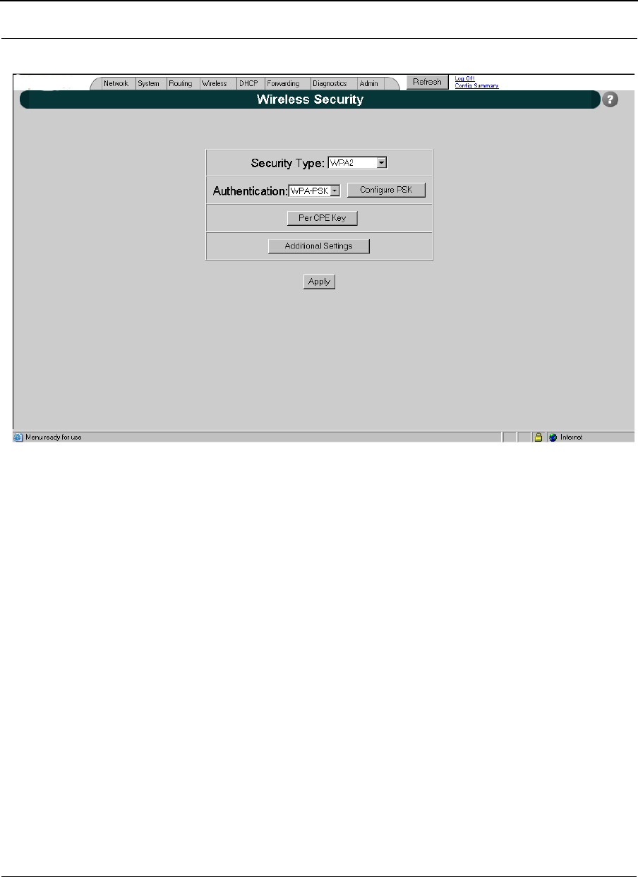
Star Base Mode
Figure 8-3: Network Security-Wireless Security
Security Type WPA, WPA2, WPA/WPA2, or V.1X Compatible
Authentication WPA-PSK
Configure PSK to access the "WPA Pre-shared Key" Page to
Configure the PSK.
Per CPE Key to access "Per CPE PSK" Page.
Additional Settings to access the "Additional Settings" Page.
Apply changes are taken effect when this button is entered.
Part # 34357-MNL Rev. B SPEEDLAN 9200 User Guide
8-8
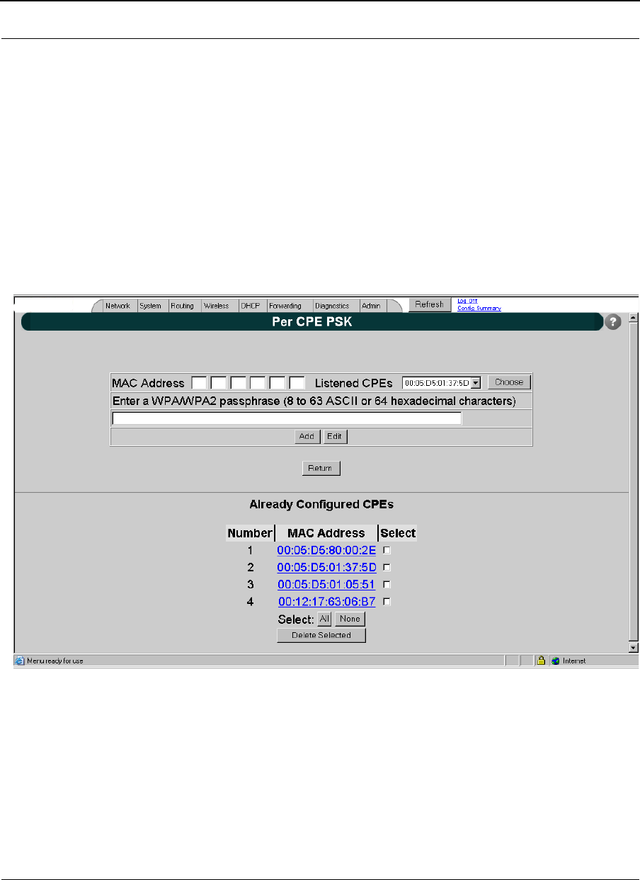
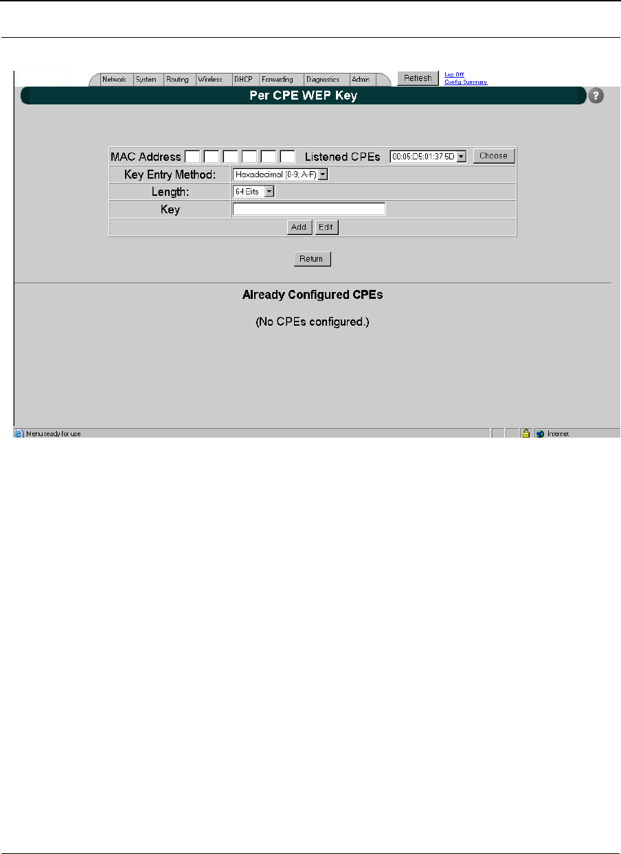
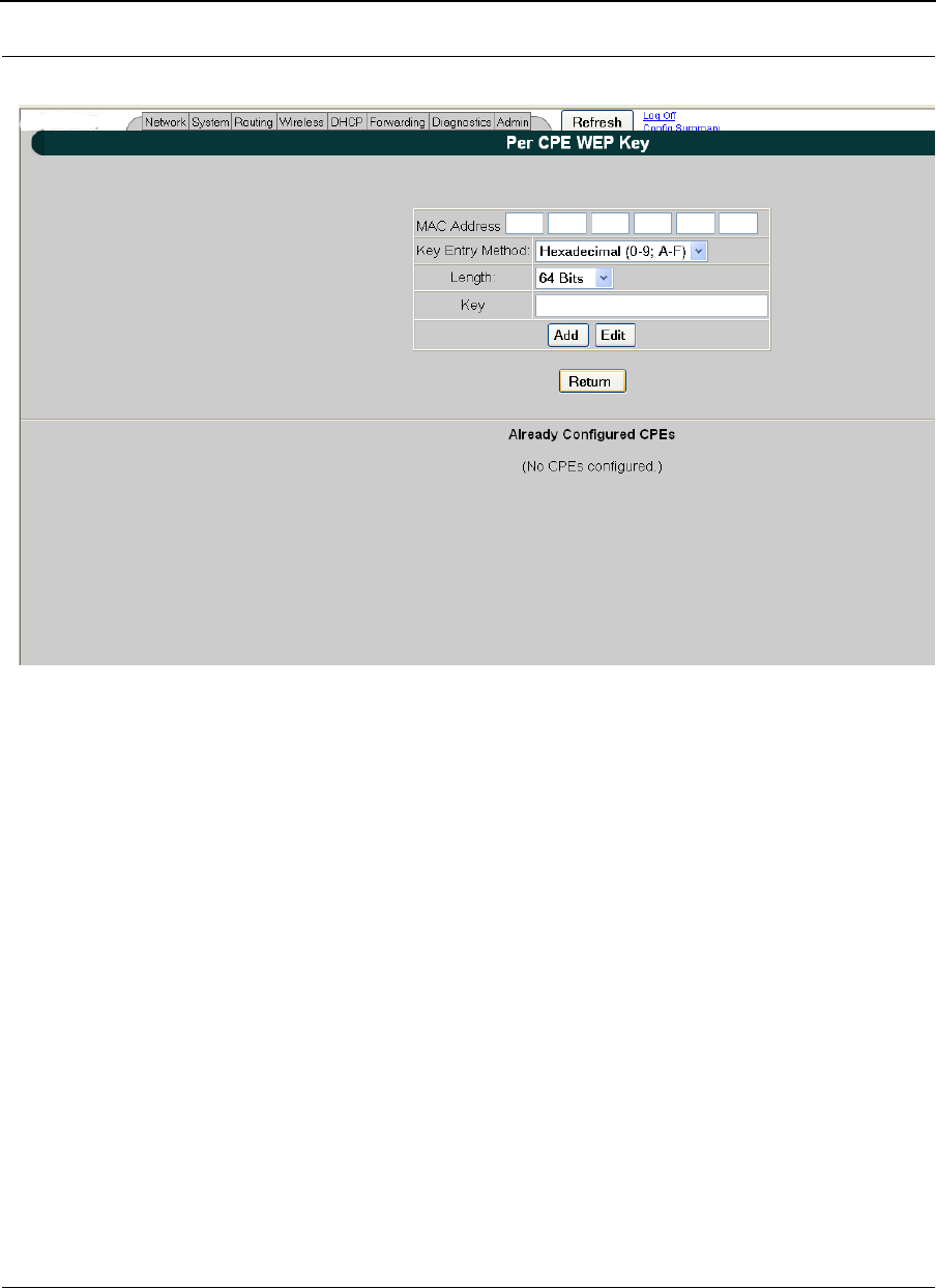
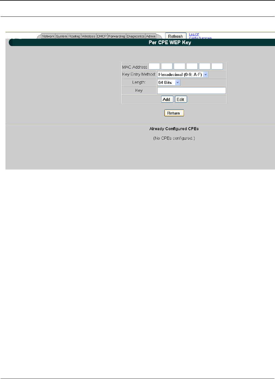
Per CPE Key
When PSK is used in a Star network, CPEs can negotiate a pairwise cipher. However, any
CPE can derive the pairwise keys of any other that uses the same PSK by capturing the
first two messages of the 4-Way Handshake. This provides malicious insiders with the
ability to eavesdrop as well as the ability to establish a man-in-the-middle attack.
To prevent such kind of attacks, SPEEDLAN9200 supports per station PSK.
The "Per CPE PSK" configuration page is used to configure a unique PSK for each CPE.
Figure 8-4: Network Security-Per CPE PSK
SPEEDLAN 9200 User Guide Part # 34357-MNL Rev. B
8-9
MAC Address MAC Address of the remote CPE.
WPA/WPA2 Passphrase passphrase for the PSK
Already Configured CPEs CPEs' MAC Address list
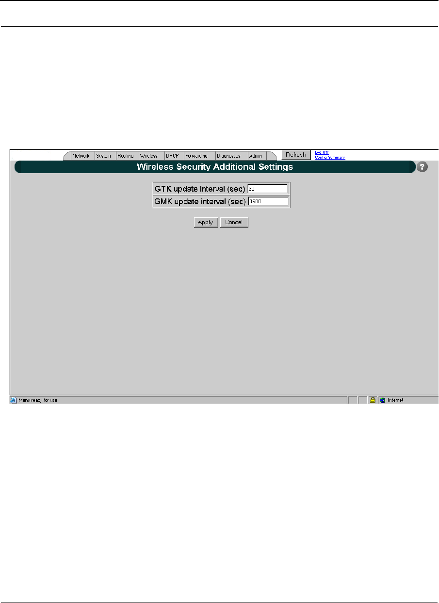
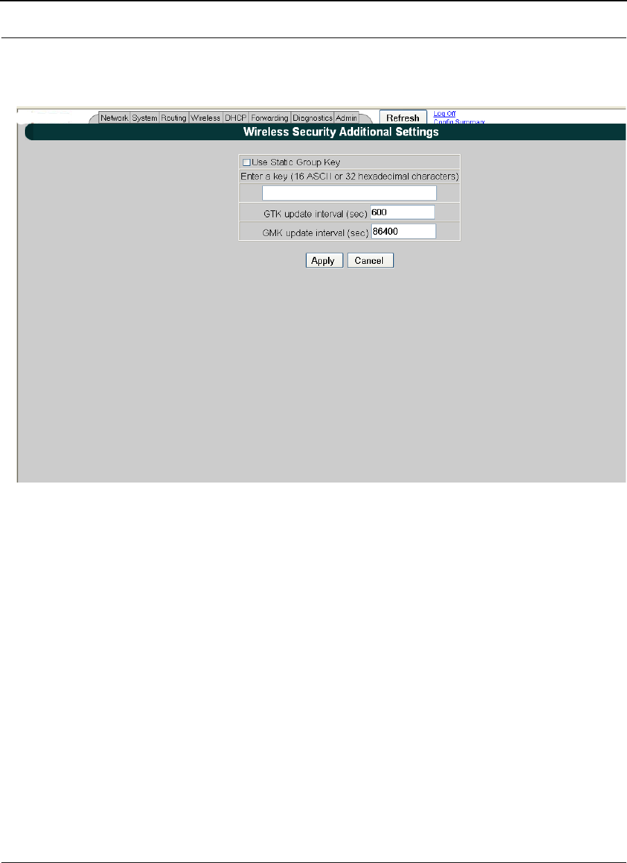
Additional Security Settings
Figure 8-5: Network Security-Additional Security Settings
GTK update interval (sec) Specify the time interval (in seconds) for re-
keying GTKs (Group Transit Key) GTK is the
encryption keys for Broadcast/Multicast
frames. The Star Base unit generates and
Part # 34357-MNL Rev. B SPEEDLAN 9200 User Guide
8-10
distributes a new group key on the regular
basis.
GMK update interval (sec) Specify the time interval (in seconds) for re-
keying GMK (Group Master Key). GMK is
used internally to generate GTKs.
Star CPE Mode
Security Type WPA, WPA2 or WPA/WPA2
Authentication WPA-PSK
Configure PSK to access the "WPA Pre-shared Key" Page to
configure the PSK.
Apply changes are taken effect when this button is entered.
Figure 8-6: Network Security-Star CPE Mode
SPEEDLAN 9200 User Guide Part # 34357-MNL Rev. B
8-11
Mesh Mode
Security Type WPA, WPA2 or WPA/WPA2
Authentication WPA-PSK
Configure PSK to access the "WPA Pre-shared Key" Page to
configure PSK
Enable Per Node Security enable/disable Per Node Security
Per Node Key to access "Per Node PSK" Page
Additional Settings to access the "Additional Settings" Page.
Apply changes are taken effect when this button is
entered.
Figure 8-7: Network Security-Per Node Key

Part # 34357-MNL Rev. B SPEEDLAN 9200 User Guide
8-12
Security Type WPA, WPA2 or WPA/WPA2
Authentication WPA-PSK
Configure PSK to access the "WPA Pre-shared Key" Page to
configure PSK
Enable Per Node Security enable/disable Per Node Security
Per Node Key to access "Per Node PSK" Page
Additional Settings to access the "Additional Settings" Page.
Apply changes are taken effect when this button is
entered
Per Node PSK
SPEEDLAN9200 supports per link PSK for stronger security. The "Per Node PSK"
configuration page is used to configure a unique PSK for the link between this unit and
any one of the remote units.
SPEEDLAN 9200 User Guide Part # 34357-MNL Rev. B
8-13
Figure 8-8: Network Security-Per Node PSK
Part # 34357-MNL Rev. B SPEEDLAN 9200 User Guide
8-14
Additional Settings
Figure 8-9: Network Security-Additional Settings
Use Static Group Key enable/disable the use of the static group
key. The static group key is used by AES-
CCMP cipher to protect multicast/broadcast
in ad-hoc network only. The decryption of
frames is handled with on-chip cipher.
Static Group Key specify static group key to protect multicast/
broadcast frames.
GTK update interval (sec) Specify the time interval (in seconds) for re-
keying GTKs (Group Transit Key).The GTK
SPEEDLAN 9200 User Guide Part # 34357-MNL Rev. B
8-15
is the encryption keys for Broadcast/
Multicast frames.
GMK update interval (sec) Specify the time interval (in seconds) for re-
keying GMK (Group Master Key). GMK is
used internally to generate GTKs.
WEP Security
There are two different approaches to using keys when WEP security is configured:
•Base unit and all CPE(s) units in Star network or all the units in Mesh network use
a single set of keys.
•The key used between each CPE and Base or the key used between two Mesh nodes
is specific to that connection and not known to other CPE(s)/Mesh node.
This section describes the WEB Configurator Pages used to configure both default and
per-CPE/per-Node WEP keys.
Figure 8-10: Network Security-WEP (Per CPE Key)
Part # 34357-MNL Rev. B SPEEDLAN 9200 User Guide
8-16
Figure 8-11: Network Security-WEP (Per Node Key)
The Per CPE Key Configuration page is used to configure unique keys for each CPE.
SPEEDLAN 9200 User Guide Part # 34357-MNL Rev. B
8-17
Figure 8-12: Network Security-WEP (Per CPE Key) part 2
Part # 34357-MNL Rev. B SPEEDLAN 9200 User Guide
8-18
Figure 8-13: Network Security-WEP (Per CPE Key) part 3
SPEEDLAN 9200 User Guide Part # 34357-MNL Rev. B
8-19
Figure 8-14: Network Security-WEP (Per CPE Key) part 4
MAC Address Specify the MAC address of CPE to provide a unique
WEP key.
Key Entry Method Specify key entry method: hexadecimal or ASCII
Key Length Specify the length of the encryption key. Allowed
lengths are 64, 128 and 152 bits.
Key Specify the encryption key
Add Add the encryption key to the configured CPEs list
Edit edit the selected CPE from the already configured
CPEs list

Part # 34357-MNL Rev. B SPEEDLAN 9200 User Guide
8-20
Enabling WEP Security Between a SPEEDMesh-Enabled Client and
SPEEDLAN 9200
In a SPEEDLAN 9200 network, you can authenticate a SPEEDMesh-enabled client (PDA
or laptop) with a standard security called Wired Equivalent Privacy (WEP). WEP
encrypts data that is being transmitted over the wireless LAN. WEP protects the wireless
links between clients and SPEEDLAN 9200 routers.
Note: WEP is an encryption scheme used to protect wireless data communications. WEP
uses 64-bit, 128-bit or 152-bit key sizes to provide access control to wireless network and
encryption security for each data transmission. To decode a data transmission, each point
in a network must use an identical 64-bit, 128-bit or 152-bit key.
To enable WEP security, do the following:
1If the Network Security Configurations page is not displayed on your screen,
choose Security from the Network menu. On the bottom section of the
Network Security Configurations page, choose WEP from the Encryption Type
drop-down list. "None" is selected by default. (If you select None, encryption is
disabled.)
2Choose Hexadecimal or ASCII Text from the Key Format drop-down list.
•"Hexadecimal" is a Base-16 numbering system. The means the 16 sequential
numbers are used as a base unit (i.e., "0-9" and "A-F").
•In ASCII text, each numeric, alphabetic or special character is represented
with a 8-bit binary number (i.e., a consecution of eight 0s or 1s).
3Select Key 1-3 from the Transmit Key drop-down list.
4Select the length for the Transmit key by choosing either 64 Bits,128 Bits or 152
Bits from the Length drop-down list.
Note: 40-bit WEP and 64-bit WEP are two different names for the same encryption
method. This level of WEP encryption has been called "40-bit" because it uses a 40-bit
secret key along with a 24-bit initialization vector (i.e., 40 + 24 = 64). The same is true for
104-128 bit and 128-152 bit WEP.
5In the "Key1-3 text" boxes, enter the key value. For hexadecimal: a maximum of
"10 "characters for 64 bits, "26" characters for 128 bits and 32 characters for
152 bits). For ASCII: a maximum of "5 characters for 64 bits, "13" characters
for 128 bits and 16 characters for 152 bits.)
6Click Apply to implement your changes.
SPEEDLAN 9200 User Guide Part # 34357-MNL Rev. B
8-21
Note: To enable the SPEEDMesh client, you must select the Enable Mobile Client check
box. For more information, see Enabling/Disabling the SPEEDMesh-Enabled Client,
page 4-6.
If WEP encryption is enabled, then:
•All frames are WEP-encrypted, regardless of the packet’s destination
address in the case if AES encryption is disabled, and
•All non-unicast frames are WEP-encrypted, regardless if AES is enabled or
disabled.
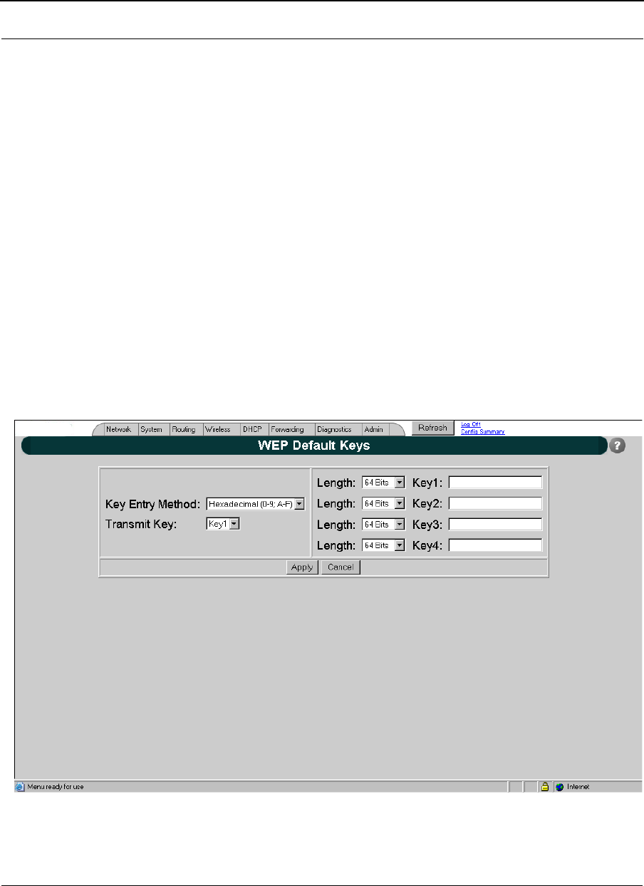
Configuring of WEP Default Keys - Shared keys
The WEP keys are used when static WEP cipher suit is selected to protect unicast or/and
broadcast/multicast frames. To configure static WEP keys the "WEP Shared Keys" page is
used (see figure below).
Figure 8-15: Network Security-WEP Default Keys

Part # 34357-MNL Rev. B SPEEDLAN 9200 User Guide
8-22
Key Entry Method Select the method for WEP keys: hexadecimal (0-9,
A-F), or ASCII text (all keyboard characters except
spaces).
Transmit Key Specify the default key index used for encryption
outgoing packets.
Length Specify the length for one of the four keys. Allowed
values Are 64, 128 and 152.
Key(1/4) Specify one of the four default WEP keys.

SPEEDLAN 9200 User Guide Part # 34357-MNL Rev. B
8-23
Notes:_____________________________________________
__________________________________________________
__________________________________________________
__________________________________________________
__________________________________________________
__________________________________________________
__________________________________________________
__________________________________________________
__________________________________________________
__________________________________________________
__________________________________________________
__________________________________________________
__________________________________________________
__________________________________________________
__________________________________________________
__________________________________________________
__________________________________________________
__________________________________________________
__________________________________________________
__________________________________________________
__________________________________________________
__________________________________________________
__________________________________________________
__________________________________________________
__________________________________________________
__________________________________________________
__________________________________________________
__________________________________________________
__________________________________________________
__________________________________________________

Part # 34357-MNL Rev. B SPEEDLAN 9200 User Guide
8-24

Chapter 9
Basics of IP Addressing
Main sections in this chapter:
• What is an IP address?, page 9-2
•Internet Address Classes, page 9-2
•How does a network administrator assign an IP
address?, page 9-7
•What is DHCP?, page 9-8
•What is NAT?, page 9-9
•NAPT, page 9-10
•Diagram of Outgoing NAT, page 9-11
•Diagram of Incoming NAT, page 9-12
•Basics of Routing, page 9-13

Part # 34357-MNL Rev. B SPEEDLAN 9200 User Guide
9-2
Basics of IP Addressing
IP Addressing is important because it tells the network how to locate the computers or
network equipment connected to it. IP addresses are given so each computer or equipment
on the network has a unique routable address. IP addressing provides the following
information:
•Provides communication between different platforms and diverse systems
•Provides universal data transfer over large geographic distances
•Has been "adopted" as a standard in the computer industry
What is an IP address?
An IP address is a unique 32-bit identifier that contains:
•Four octets (e.g., decimal 192.0.2.56).
•Two sections: the network address and the node address (also known as the host
address).
The following examples show the conversion of the same IP address into several different
formats:
•Hexadecimal (82.39.1E.38)
•Binary (10000010.00111001.00011110.00111000).
Internet Address Classes
Understanding this methodology is difficult; therefore, let's explain this in easier terms.
The first octet(s) defines the "class" of the address, which is the only method to tell the size
of the network (how big) and where the internet address belongs.
There are three main classes:
•Class A: 35.0.0.0
•Class B: 128.5.0.0
•Class C: 192.0.2.0
-non-bolded text = Part of network address
-bolded text = Part of local address (node section)

SPEEDLAN 9200 User Guide Part # 34357-MNL Rev. B
9-3
This specification simplifies the way routers handle the messages (packets) and speed up
the forwarding process.
In fact, IP defines five classes:
•Class A addresses uses 1 octet for the network portion and 3 octets for the node
(or host) section of the address. This provides up to 128 networks with 16.7 mil-
lion nodes for each network.
•First octet is assigned as network address
•Remaining octets used for node addresses
•Format: network, node, node, node
•In IP address 49.22.102.70, "49" is network address and "22.102.70" is the
node address—all machines on this network have the "49" network address
assigned to them
•Maximum of 16,777,216 node addresses
•Class B addresses uses 2 octets for the network portion and 2 octets for the node
(or host) section of the address. This provides up to 16,384
networks with 64,534 nodes for each network.
•First 2 octets are assigned as network address
•Remaining octets used for node addresses
•Format: network, network, node, node
•In IP address 130.57.30.56, "130.57" is the network address, and "30.56" is
the node address
•Maximum of 65,534 node addresses
•Class C addresses use 3 octets for the network portion and 1 octet for the node
(or host) section of the address. This provides 16.7 million networks with 256
nodes for each network.
•First three octets are assigned as network address
•Remaining octet used for node address
•Format: network, network, network, node
•In IP address 192.0.2.102, "192.0.2" is the network address, and "102" is
the node address
•Maximum of 28 or 254 node addresses

Part # 34357-MNL Rev. B SPEEDLAN 9200 User Guide
9-4
•Class D
•Range is 224.0.0.0 to 239.255.255.255
•Used for multicast packets (i.e., host sends out router discovery packets to
learn all of the routers on the network)
•Netmask = /32
•Class E
•Range is 240.0.0.0 to 255.255.255.255
•Reserved for future use
Note: Class D & E should NOT be assigned to network assignment of IP
addresses. In addition, the first octet, 127, is reserved. In each network defi-
nition, the first node number (i.e., "0") is used to define the network (i.e.,
"255"). The last number is known as the broadcast address.
Note: Public addresses can include a network address assigned from the network
administrator or from the IP provider. Also, there is one network in each
class that is defined for private use, allowing the creation of
internal networks. These addresses are Class A: 10.0.0.0, Class B:172.6.0.0,
and Class C: 192.168.0.0.

SPEEDLAN 9200 User Guide Part # 34357-MNL Rev. B
9-5
Subnetting a Network
The increasing number of hosts and networks make large impractical address blocks that
are not smaller than 255. In order to keep the IP address block small, so routers can
manage them more efficiently, a smaller network definition is created. This is called a
subnet. Subnets are intended to:
•Reduce network traffic
•Optimize performance
•Simplify management
•Create more effective and efficient addresses for large geographic distances
Default Subnet masks
•Class A: 255.0.0.0.
•Class B: 255.255.0.0.
•Class C: 255.255.255.0.
Note: Subnet mask is bolded and corresponds to the network portion of the IP address.
What is a Subnet?
A subnet allows you to create multiple networks within one Class A, B, or C network. Each
subnet contains a netmask that helps routers identify the subnet beginning and size.
What is a Subnet Mask?
A subnet mask allows you to mask section(s) (depending on the class specified) of the
octets in the network address. Each octet used in the subnet mask is assigned to a data
link. The leftover octet(s) are assigned to the remaining nodes.
For more information on subnetting, see the example below and Diagram of Subnetting a
Network, page 9-6.
Example of Subnetting:
For example, a Class C network contains three masked octets (255.255.255). The last
octet (0) identifies nodes (i.e., computers).
If Router D is reading IP Addresses 192.0.2.1 (let's call this IP Address 1) and 192.0.2.64
(let's call this IP Address 2) on this Class C network, it would send IP Address 1 to Subnet
Part # 34357-MNL Rev. B SPEEDLAN 9200 User Guide
9-6
A and IP Address 2 to Subnet B. The remaining nodes in each subnet (A through D) on
this network can contain up to 254 pieces of network equipment (computers, printers, fax
machines, bridges or routers, etc.).
Diagram of Subnetting a Network
Figure 9-1: Subnetting diagram
Still confused?
An easier method to explain this concept is to use the classic "mailing" analogy used in IP
addressing. Consider that this network, called Long Street, is four blocks long. There are
254 houses on Long Street, and each block contains 64 houses. Houses 1 to 63 reside on
Block A. Houses 64 to 127 reside on Block B. Houses 128 to 191 reside on Block C.
Houses 192 to 254 reside on Block D. Think of each block as a subnet. This means that
Blocks A, B, C, and D are all part of Long Street, which is also known as the network in
this example. The mailman would organize the letters (or IP addresses for network
Internet
Router D
Router B
Router C
Computer Computer
Computer
Computer
Computer Computer Computer
Computer Computer Computer
Long Street
Subnet A
IP Address: 192.0.2.1
Subnet Mask: 255.255.255.192
Subnet B
IP Address: 192.0.2.64
Subnet Mask: 255.255.255.192
Subnet C
IP Address: 192.0.2.128
Subnet Mask: 255.255.255.192
Subnet D
IP Address: 192.0.2.192
Subnet Mask: 255.255.255.192
Router A

SPEEDLAN 9200 User Guide Part # 34357-MNL Rev. B
9-7
equipment) by creating four piles (one for each block, or subnet). As soon as the mailman
picks up pile A in his hand, he knows which block to turn on. This same reasoning applies
to piles B, C, and D as well. Router D knows exactly which subnet to transfer (or turn) the
packets to by reading its IP and subnet mask address. Note that each subnet on this
network is 255.255.255.192. Why is 192 the last octet in the subnet mask and not 64? The
last octet, 192, is the mask that allows 64 "houses" to reside on the street.
Note: If the network is managed by a Simple Network Management Protocol for
local or Internet access, each interface must contain a unique IP Address.
This is a benefit of static or dynamic addressing.
How does a network administrator assign an IP address?
IP addresses are supplied by the network administrator, the ISP, or hosting company.
The two types of IP addressing—manual (static) and automatic (dynamic) addressing—
are described below.
•Manual (static) Addressing - Is ’Manually Configure’ option on Interfaces
Parameters page of SPEEDLAN 9200 Configuator
Each device connected to the Internet must have its own unique IP address. Also,
if a computer is being used as a server, you will assign it a permanent IP
address. This enables other computers to connect to it. Static addressing is also
beneficial to users that need to maintain a "constant" connection to the Internet.
This will enable users to easily access the IP address.
•Automatic (dynamic) Addressing - Is ’Use DHCP’ option on Interface
Parameters page of the SPEEDLAN 9200 Configurator.
A DHCP (Dynamic Host Configuration Protocol) server assigns the IP address
to each computer as the computer connects to the network. If a computer moves
to a new network (i.e., great for temporary employees or mobile users), it must be
assigned a new IP address for that network. DHCP can be used to manage these
assignments automatically. DHCP is described in further detail below.
What is DHCP?
Dynamic Host Configuration Protocol (DHCP) allows network administrators to assign
dynamic IP addresses for the period of time needed to connect to the Internet. Think of
DHCP as leasing an apartment. A prospective tenant may not need to live in an apartment
for two years, maybe just a year. Therefore, the tenant will only sign a one-year lease
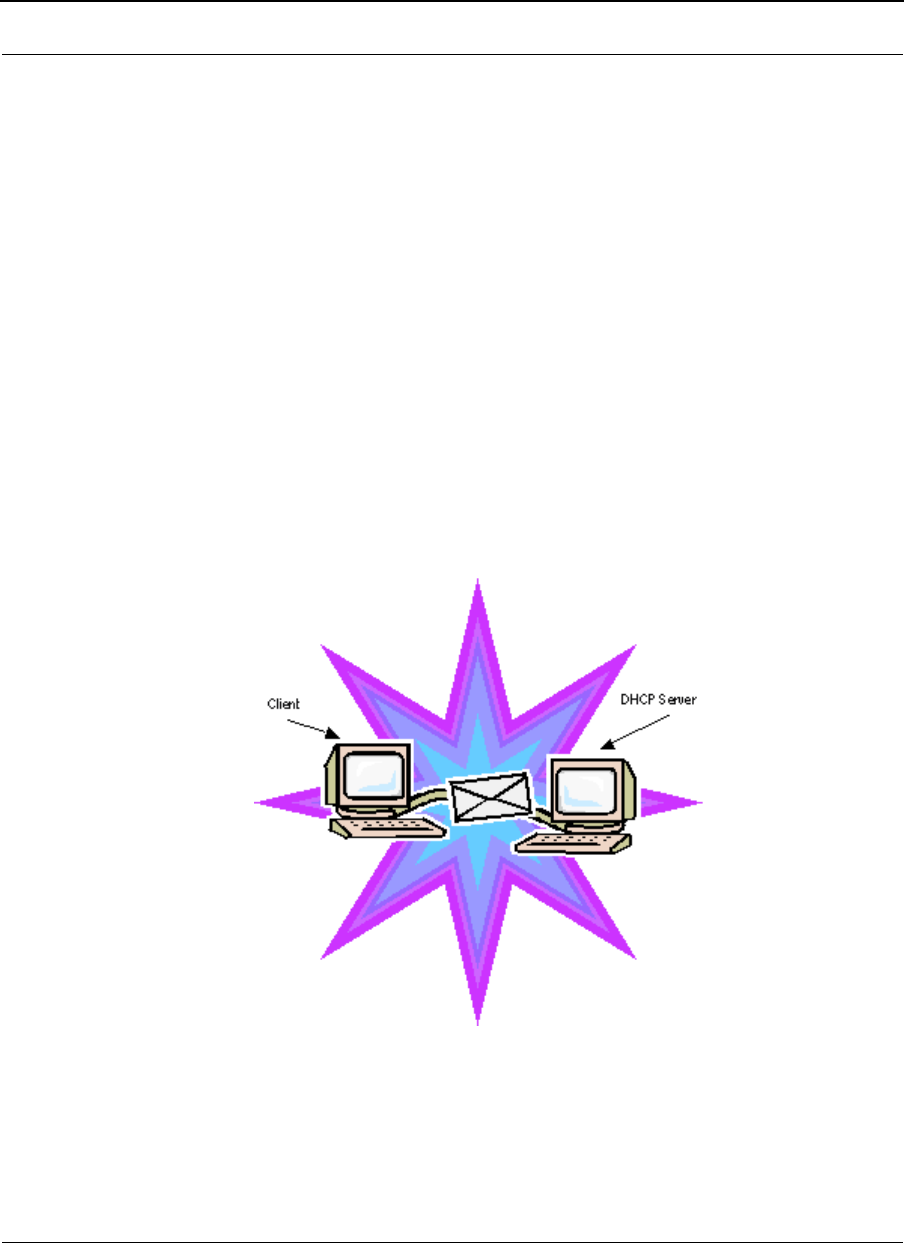
Part # 34357-MNL Rev. B SPEEDLAN 9200 User Guide
9-8
agreement. For example, each time a computer is set up to connect to the Internet, the
network administrator uses DHCP to automatically assign the computer a unique IP
address. That computer will give up its IP address when it is no longer needed (when the
lease has ended) allowing new a computer (or a new tenant) on the same network to use it.
This benefits educational and corporate settings where users often log on to different
computers. In this case more IP addresses outnumber computers because you can quickly
reconfigure the network if needed from a centralized location.
Servers that utilize DHCP resolve security issues, costly IP addressing services, and
compatibility problems. DHCP is an alternative to BOOTP, which reduces the agony of
assigning static IP addresses and also provides advanced configuration options.
Note: The figure on the next page may help you understand how DHCP assigns
and IP address.
Figure of DHCP Addressing
Figure 9-2: DHCP client and server
1The client asks DHCP server for IP address and configuration if needed.
2The DHCP server assigns an available IP address to client.

SPEEDLAN 9200 User Guide Part # 34357-MNL Rev. B
9-9
3The client takes IP address from DHCP server and requests any additional
configuration needed.
4DHCP server confirms IP address and configuration.
What is NAT?
Network Address Translation (NAT) is the conversion of an Internet Protocol address (IP
address) used within one network to a different IP address within another network. One
network is designated the inside network and the other is the outside network.
Network Address Translation (NAT) occurs when there is a translation among an Internet
Protocol (IP address) used within one network (designated as inside network) to a
different IP addresses within another network (designated as outside network). Network
Address Translators (NATs) allow companies to decrease the number of global IP
addresses. This enables companies to communicate with other devices on the Internet with
a single global IP address (or more than one IP address).
For example, a company can provide its clients with one IP address, allowing access to
the company's firewall only. This IP address is not a "real" address on the company's
internal network, but it is successfully translated to the correct IP location through NAT
(i.e., NAT router). Therefore, the company controls access through firewalls and provides
multiple IP addresses to outside customers without excessive limited resources, or
"global" Internet IP protocols.
NAPT
What differentiates NAPT from NAT? NAPT (or Network Address Port Translation) not
only translates the IP address but also the transport layer port. Thus, if an inbound packet
was addressed to a web server port on 80, the NAPT device would translate and pass to
the packet to the private network's web server. Without port translation, the NAT device
has no means of knowing which host in the private network can pass packets to other
devices. For an example see, Diagram of Incoming NAT, page 9-12.
Part # 34357-MNL Rev. B SPEEDLAN 9200 User Guide
9-10
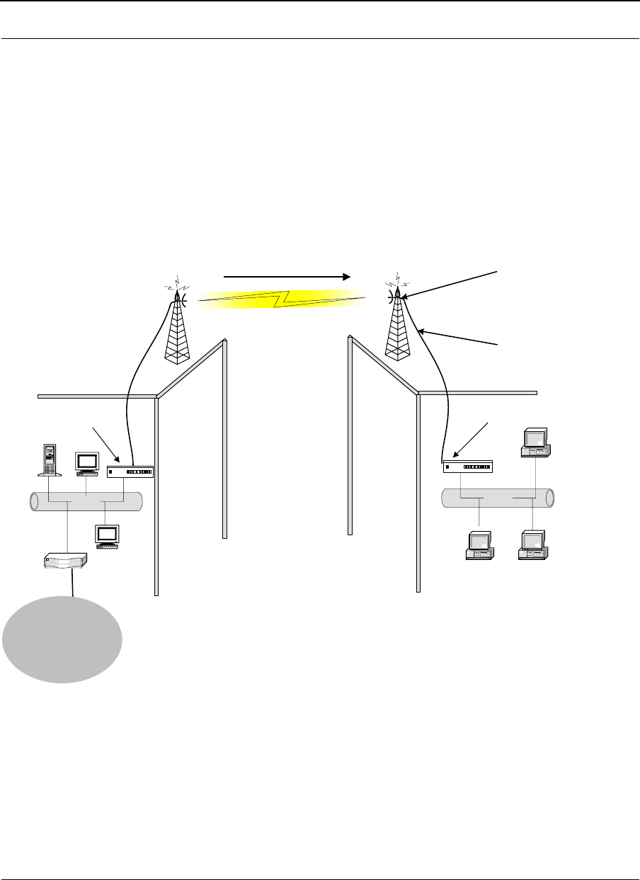
Diagram of Outgoing NAT
Figure 9-3: Outgoing NAT
As the packet is transmitted from the private network (in Building B) across the public
network (public address in Building A and the Internet), the packet will be re-addressed as
192.0.2.3 (public address). When the packet returns to Building B, the packet will be re-
addressed to the IP address of the private network by using the MAC address contained in
the header to identify the destination.
Inbound Port 80 request is re-addressed
to Private address 10.0.0.3. Then, it is
forwarded across the private network
Ethernet
Router
192.0.2..1
Private Address on Local Interface
10.0.0.1
10.0.0.2
10.0.0.4
Ethernet
Public Address on Remote Interface
192.0.2.3
Building A Building B
SPEEDLAN 9000 Router
192.0.2.0
SPEEDLAN 9000 Router
10.0.03
–
Internet
SPEEDLAN 9200 User Guide Part # 34357-MNL Rev. B
9-11
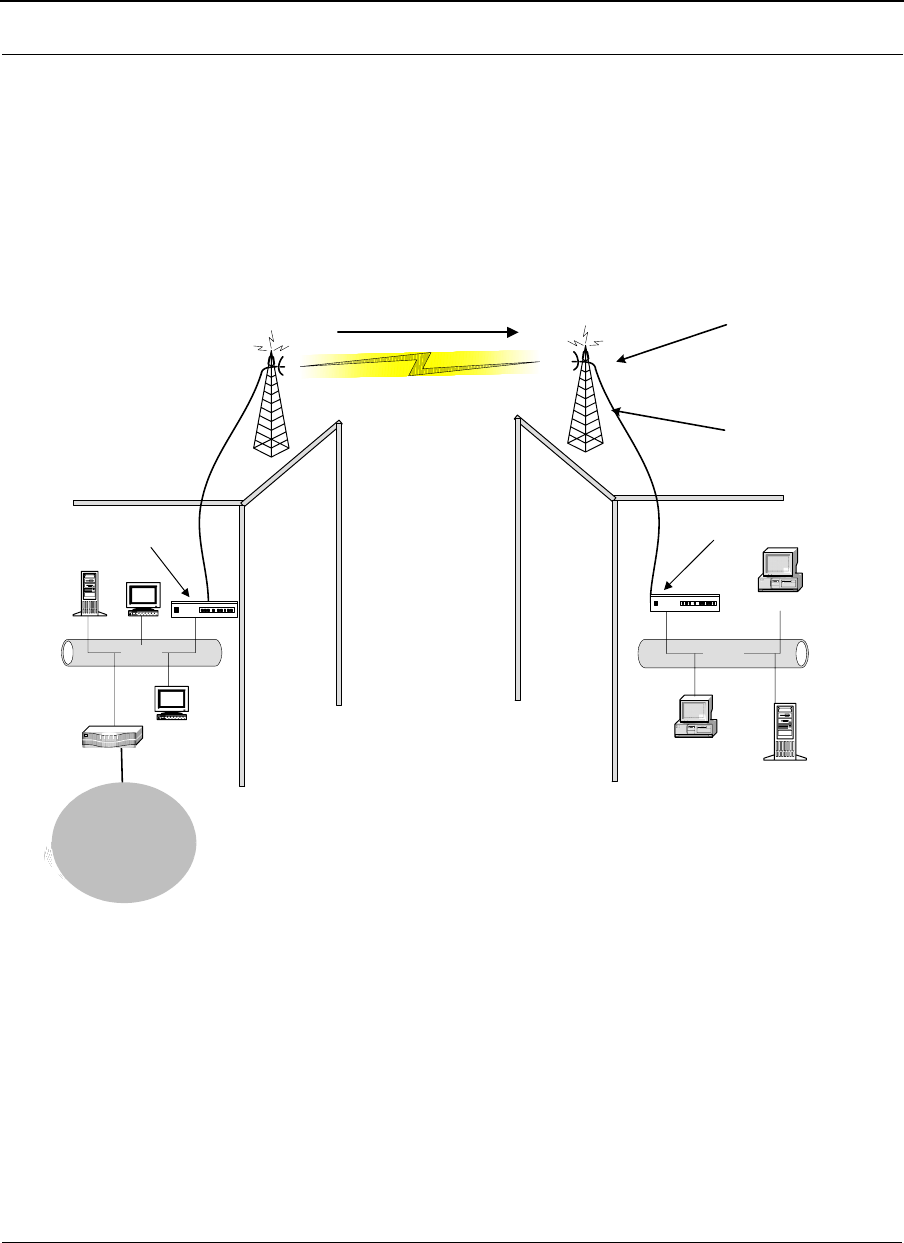
Diagram of Incoming NAT
Figure 9-4: Incoming NAT
Incoming NAT allows you to specify ports on the private network (Building B) that you
would like to be available on the public network (Building A and the Internet). For
example, if a web server (IP Address 10.0.0.3) is being hosted on a private network in
Building B, you can create a pair that will specify that all requests on the public IP
address, Port 80, be forwarded to IP Address 10.0.0.3 on the private IP address, Port 80.
Inbound Port 80 request is re-addressed
to Private address 10.0.0.3. Then, it is
forwarded across the private network
Internet
Ethernet
Router
192.0.2.1
Private Address on Local Interface
10.0.0.1
10.0.0.2
10.0.0.4
Ethernet
Web Server
10.0.0.3
Public Address on Remote Interface
192.0.2.3
Building A Building B
SPEEDLAN 9000 Router
192.0.2.0
SPEEDLAN 9000 Router
Internet

Part # 34357-MNL Rev. B SPEEDLAN 9200 User Guide
9-12
Basics of Routing
A router connects two or more networks or subnetworks together and decides which
direction it should send each packet. A router is typically a gateway (where one network
meets another). A router operates at the Network Layer of the OSI model. This means a
router sends information based on the packet's IP address instead of the Ethernet (MAC)
address (as in bridging).
Routing protocols use special metric algorithms when determining the best path for a
packet to travel. All of this information is stored in a routing table. Some of this
information includes hop count and destination information. The routing table also stores
when the receiver gets the packet and lets the sender know that is was received.
Note: For more information about routing, see www.whatis.com, http://
www.techweb.com/encyclopedia/, http://www.computeruser.com/resources/dictionary/
dictionary.html, or search for "basics of routing" on the World Wide Web.

SPEEDLAN 9200 User Guide Part # 34357-MNL Rev. B
9-13

Part # 34357-MNL Rev. B SPEEDLAN 9200 User Guide
9-14
Notes:_____________________________________________
__________________________________________________
__________________________________________________
__________________________________________________
__________________________________________________
__________________________________________________
__________________________________________________
__________________________________________________
__________________________________________________
__________________________________________________
__________________________________________________
__________________________________________________
__________________________________________________
__________________________________________________
__________________________________________________
__________________________________________________
__________________________________________________
__________________________________________________
__________________________________________________
__________________________________________________
__________________________________________________
__________________________________________________
__________________________________________________

Chapter 10
Public Safety Band

Part # 34357-MNL Rev. B SPEEDLAN 9200 User Guide
10-2
Background Information on the 4.9 GHz Public Safety Band (PSB)
The Federal Communication Commission (FCC) has allocated 50 megahertz (MHz) of spectrum in the
4940-4990 MHz band (4.9 GHz band) for fixed and mobile wireless data communications, designating the
band for use in support of public safety (Public Safety Band, PSB). Specifically, the Commission adopted
two emission masks limiting interference potential for the band, one for low power and one for high-power
operations. These changes will allow public safety licensees to leverage commercial off-the-shelf (COTS)
technologies available for the U-NII and ITS frequency bands. The FCC action allows for a nationwide
focus on homeland security, and will ensure that all state and federal agencies possess the required commu-
nications resources to adequately protect the public.
This allocation will provide public safety users the additional spectrum required to support broadband
applications such as high-speed data transitions and video over wireless, which in turn enhances local area
networks for incident monitoring and supervision. The spectrum can also be used to support the dispatch
operations communications as well as safety vehicle communications. Public safety agencies will be able to
implement on-scene wireless networks for streaming video, rapid Internet and database access, and trans-
fers of large files such as maps, building layouts, medical files, and missing person images. It also allows
these agencies to establish temporary or permanent links to support surveillance operations. This allocation
gives every jurisdiction in the country access to spectrum for deployable, interoperable, broadband commu-
nications.
The spirit behind the creation of the band was to allow the public safety organizations access to inex-
pensive hardware already available for the ISM bands, but in a section of the spectrum that is not available
to the general public.
Key Facts of the 4.9 GHz PSB band
• The FCC allocates the 4.9 GHz band for fixed and mobile communication.
• The FCC designates the 4.9 GHz band for use solely in the support of public safety encompassing the
protection of life, health and property
• Users must be a state or local government entity or non-government entity authorized by a local or state
public safety entity.
• Provide services that are not commercially available to the public.
• The FCC rules allow a maximum total power output of 33 dBm (2 W) per channel and a maximum
antenna gain of 9 dBi for a maximum EIRP of 42 dBm.
• Public safety agencies can apply for licenses to use the spectrum within their areas of jurisdiction.
• The FCC rules permit broadband mobile operations, fixed hotspot use and temporary fixed links.
• Fixed point-to-point operations are also permitted but this use requires a separate license from the FCC
for each station.
• The FCC rules prohibit use for services that are made commercially available to the public
• The new looser emissions mask is designed to allow users to utilize off the shelf technology to signifi-
cantly reduce cost and time

SPEEDLAN 9200 User Guide Part # 34357-MNL Rev. B
10-3
Eligibility for 4.9 GHz PSB Use
All state and local government entities that provide public safety services, this is defined as their primary
focus being the protection for the safety of life, health, or property; are eligible to apply for a 4.9-GHz
license. The control of the licensing is being managed at the state and local level to facilitate priority and
availability of the 4.9 GHz band. Entities that do not meet these eligibility requirements, but that provide
services in support of public safety, such as private infrastructure companies, can negotiate sharing agree-
ments with license holders.
4.9 GHz PSB Frequency Band Plan
The 4.9 GHz band ranges from 4940.5-4989.5 MHz and can be segregated out using 1, 5, 10, 15, and 20
MHz of bandwidth.
4.9 GHz PSB Licensing Requirements
A 4.9 GHz band license gives the licensee authority to operate on any authorized channel in this band within
the applicant's legal jurisdiction such as city, county, or state. The 4.9 GHz band is shared by all licensees,
who must coordinate their usage of the band with other licensees within their areas of authority. The 4.9
GHz licenses are granted for a 10-year term.
The license gives authority to construct and operate:
• Any number of base stations anywhere within the area authorized by the license
• Base and mobile units, including portable and handheld units
A 4940-4990 MHz band license does not give the licensee authority to operate permanent fixed point-to-
point stations. Licensees choosing to operate such fixed stations must license them individually on a site-
by-site basis. Such fixed operation will be authorized only on a secondary, non-interference basis to base,
mobile and temporary fixed operations.
4.9 GHz PSB Peak Power Limits
The transmitting power of radios operating in the 4940-4990 MHz band must not exceed the following max-
imum limits:
Channel Bandwidth in MHz Class A peak output power in dBm Class B peak output power in dBm
120 7
527 14
10 30 17
15 31.8 18.8
20 33 20

Part # 34357-MNL Rev. B SPEEDLAN 9200 User Guide
10-4
4.9 GHz PSB Emission Mask
The FCC has adopted two emission masks for use in the 4.9 GHz band. The first being DSRC-A, is a mask
strictly for low-power applications. The second being the DSRC-C mask is strictly for high-power applica-
tions. The DSRC-A mask is identical to the mask defined in the widely used 802.11Wi-Fi standard, which is
most commonly used in-home wireless LANs and consumer hotspots. These 802.11 devices are readily
available for purchase and significantly reduce cost and time to market for wireless deployments.
Higher power units that are above 20 dBm of output power are required for deploying mobile networks and
need to employ the DSRC-C mask.
SPEEDLAN 4.9 GHz PSB Introduction
The SPEEDLAN 9200 wireless router is now certified to operate under Part 90, Subpart Y of the FCC Rules
to operate as a high power device in the 4.9 GHz PSB band with 5, 10 and 20MHz channel bandwidths.
All of the features available in SPEEDLAN including Point to Multipoint, Point to Point and Mesh topolo-
gies and all security features as presented in the User guide are available for use in the 4.9PSB.
The wireless configuration screen was added to the router functionality to allow configuring the RF to oper-
ate in this band.
In fact the SPEEDLAN 9200 hardware is the same for 2.4GHz, 5.8GHz and 4.9GHz and only the software
has been changed to enable 4.9GHz PSB operation.
• 20 MHz bandwidth settings may operate at signaling rates up to 54 Mbps,
• 10 MHz bandwidth settings may operate at signaling rates up to 54/2 (27) Mbps and
• 5 MHz bandwidth settings may operate at signaling rates up to 54/4 (13.5) Mbps.
SPEEDLAN 9200 User Guide Part # 34357-MNL Rev. B
10-5
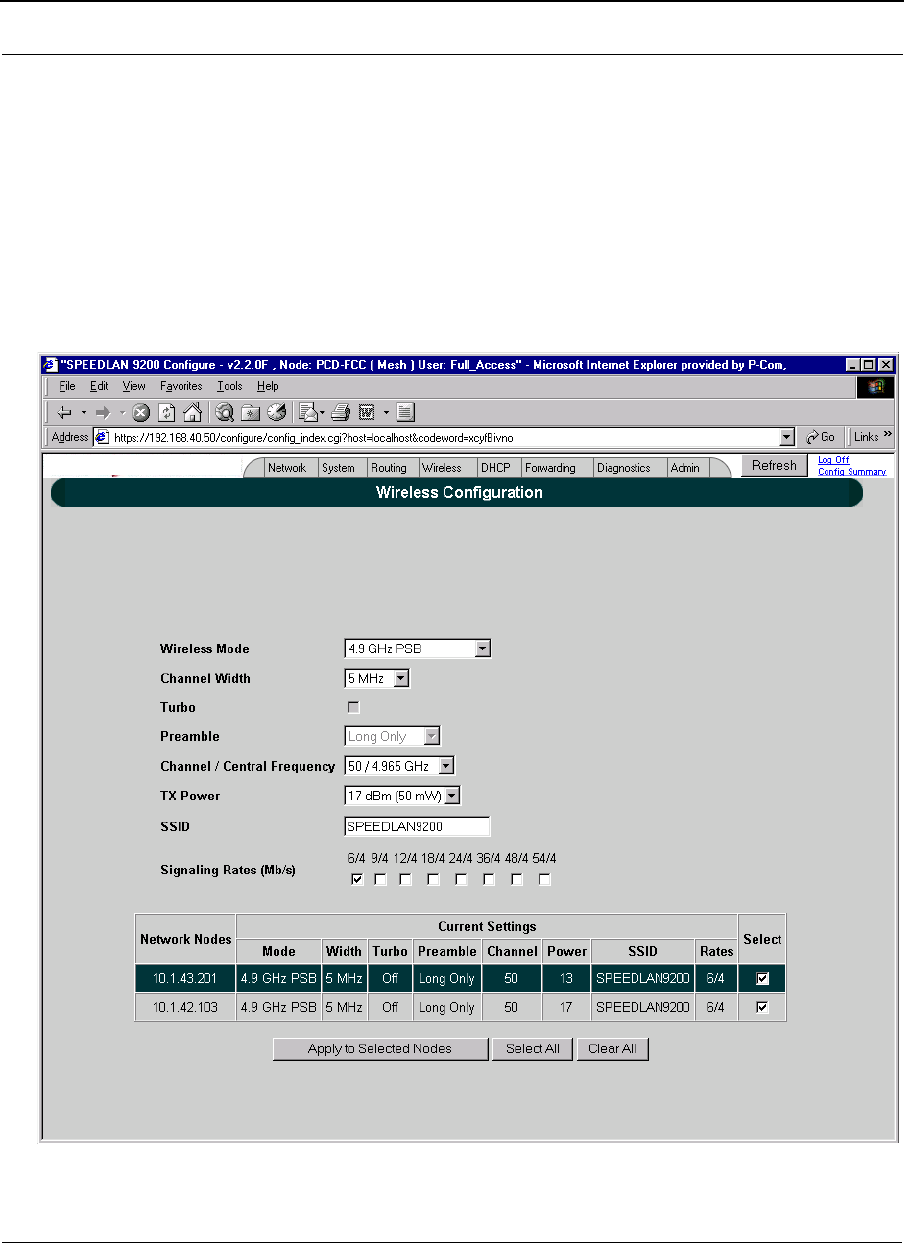
SPEEDLAN 4.9 GHz PSB Wireless Configuration using the https:// Configurator
Follow the guidelines in the user guide to establish communications with the SPEEDLAN router. Bring up
the web based SPEEDLAN Configurator.
Select Wireless | Configuration from the menus in the Configurator.
The following screen will appear to allow configuration of the 4.9PSB in the SPEEDLAN 9200

Part # 34357-MNL Rev. B SPEEDLAN 9200 User Guide
10-6
SPEEDLAN 4.9 GHz PSB Channel Plan
Table of Channel Center Frequencies vs. Channel Bandwidth:
WW Chan
Number 5 MHz BW
Frequency FCC Channel
Number 10 MHz BW
Available?
X=yes
20 MHZ BW
Available?
X=yes
Band Edge
Delta, 4940
Plus (MHz):
5 4942.5 3 N/A N/A 2.5
10 4945.0 X N/A 5.0
15 4947.5 6 X N/A 7.5
20 4950.0 X X 10.0
25 4952.5 7 X X 12.5
30 4955.0 X X 15.0
35 4957.5 8 X X 17.5
40 4960.0 X X 20.0
45 4962.5 9 X X 22.5
50 4965.0 X X 25.0
55 4967.5 10 X X 27.5
60 4970.0 X X 30.0
65 4972.5 11 X X 32.5
70 4975.0 X X 35.0
75 4977.5 12 X X 37.5
80 4980.5 X X 40.0
85 4982.5 13 X N/A 42.5
90 4985.0 X N/A 45.0
95 4987.5 16 N/A N/A 47.5

Chapter 11
Professional Installation
Guidelines
Part # 34357-MNL Rev. B SPEEDLAN 9200 User Guide
11-2
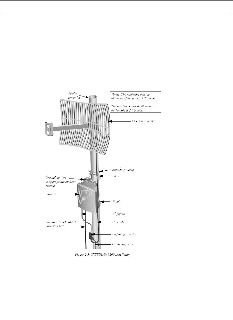
Background Information on the Installation of Speedlan 9200
Wave Wireless requires a Professional Installer to install the Speedlan 9200 product
The Speedlan 9200 was tested for compliance to the Federal Communication Commission (FCC) rules part
15.247 and the testing results indicated the need for some special guidelines for the Professional Installer to
follow when installing the Speedlan 9200.
2.4 GHz SPEEDLAN 9200 Installation Requirements
The installer is to follow the diagram in Figure 2-5 of the Speedlan 9200 User guide, Wave Wireless part
number 34357-MNL.

SPEEDLAN 9200 User Guide Part # 34357-MNL Rev. B
11-3
2.4 GHz SPEEDLAN 9200 Installation Requirements
The professional installer must follow the following guidelines in table 1 when installing the SPEEDLAN
9200 at 2.4 GHz.
For 802.11b, +17 dBm no TXPO restrictions
5.8 GHz SPEEDLAN 9200 Installation Requirements
The professional installer must follow the following guidelines in table 1 when installing the SPEEDLAN
9200 at 5.8 GHz.
The installer is to follow the diagram in Figure 2-5 of the Speedlan 9200 User guide, Wave Wireless part
number 34357-MNL. The filter is to installed directly on the antenna or in line with the lightning arrestor.
Antenna Type (802.11g), MAX TXPO Setting:
24 dBi, Parabolic Grid +17 dBm, except +15 dBm on Channel 11
16 dBi, 90° Sector +17 dBm, except +14 dBm on Channel 1 & 11
15 dBi, Yagi +17 dBm, except +13 dBm on Channel 1 & 11
12 dBi OMNI +17 dBm, except +15 dBm on Channel 1 & 11
8 dBi Patch +17 dBm, except +15 dBm on Channel 1 and
+17 dBm, except +14 dBm on Channel 11
Antenna Type (802.11a), MAX TXPO Setting:
29 dBi, Parabolic Grid +17 dBm, Band-Stop or Band Pass filter
required before Antenna
23 dBi, Panel +17 dBm, Band-Stop or Band Pass filter
required before Antenna
17 dBi, Backfire Parabolic +17 dBm, no restrictions
16 dBi, 120° Sector +17 dBm, no restrictions
8 dBi OMNI +17 dBm, no restrictions

Part # 34357-MNL Rev. B SPEEDLAN 9200 User Guide
11-4
4.9 GHz SPEEDLAN 9200 Requirements
The professional installer must follow the following guidelines in table 1 when installing the SPEEDLAN
9200 at 4.9 GHz:
4.9 GHz complies with Part 90, Subpart Y,
As per 90.1215, the maximum antenna gain 9dBi for OMNI antennas. The maximum antenna gain is 26 dBi
for directional antennas used in Point-to-Point or Point-to-Multipoint.
For each dB increase in antenna gain over the above stated values, the transmit power must be reduced
correspondingly.

Glossary for Standard Data
Communications

Part # 34357-MNL Rev. B SPEEDLAN 9200 User Guide
Glossary-2
Glossary for Standard Data Communications
Advanced Encryption Standard (AES)
Advanced Encryption Standard was adopted by the National Institute of Standards and Technology in
October of 2000. AES presents a new level in computer networking security, especially important in wireless
communications because wireless circuits are easier to tap than their hard-wired counterparts. AES is more dif-
ficult to crack than its predecessor Data Encryption Standard. SPEEDLAN 9200 products use an AES
128-bit encryption key.
Address Resolution Protocol (ARP)
ARP is the abbreviation for Address Resolution Protocol, which maps an IP address to a machine's hardware
address. Network administrators use ARP to locate systems on the LAN that are configured with incorrect IP
addresses.
Alignment
In order to create a successful link, all related equipment should be associated to its respective attachments or
equipment.
Amplitude
The magnitude of a waveform when measured from the mid-point to the peak of the wave.
Analog
A signal in the form of a continuously varying quantity such as voltage, frequency or phase.
Antenna
Device used to concentrate and direct the energy of a signal into a tight beam. Parabolic or dish, grid, and Yagi
are different varieties of antennas.
Antenna Gain
The ratio of the power radiated by an antenna in a specific direction versus the power required to produce this
same strength if an isotropic antenna were used.
Attenuation
The measure of the loss of power in a microwave signal as it travels between two points. It is measured in deci-
bels (dB).
Attenuator
A device used to reduce the RF signal level.
Azimuth
This is the direction of antenna pointing relative to true north.

SPEEDLAN 9200 User Guide Part # 34357-MNL Rev. B
Glossary-3
Band
A portion of the electromagnetic frequency spectrum.
Bandwidth
The range of frequencies over which a device will transmit information.
Bit
An abbreviation for binary digits.
Bit Error Rate
A measure of the number of errors in a digital transmission. Typically given as an exponential number that rep-
resents the ratio of errors to total bits. Example: 1E-03 = 0.001 = 1.0 x 10⁻³ and 1.0E-6 = 0.000001 = 1.0 x 10-
3. A single element in a binary code. A measure of the number of errors in a digital
transmission. Typically given as an exponential number that represents the ratio of errors to total bits.
Example: 1E-03 = 0.001 = 1.0 x 10⁻³ and 1.0E-6 = 0.000001 = 1.0 x 10⁻³.
Bridge
The function of a bridge is to connect separate networks together. This device operates at the DataLink Layer of
the OSI model. Bridges connect different network types (such as Ethernet and Token Ring) or networks of the
same type.
Byte
A data unit consisting of eight bits.
Cable
A transmission medium of copper wire or optical fiber wrapped in a protective cover.
Channel
A specific band of frequencies designated for a specific purpose; the data path between two nodes.
Classless Inter-Domain Routing (CIDR)
This is an abbreviated method of entering the netmask. For more information, see CIDR Table (For Netmask
Information Purposes) in Chapter 3.
Channel Service Unit/Data Service Unit (CSU/DSU)
A CSU/DSU is a pair of devices that adapts a dead pair (i.e., an unbiased line) to transmit
high-speed data signals. Of course, the pair is manageable and provides a status, but their
main function is be a dead-line modem. Latest versions use digital signals over the dead
line, but older models did not.

Part # 34357-MNL Rev. B SPEEDLAN 9200 User Guide
Glossary-4
Channel Spacing
Channel spacing is the spectral space between RF channels; it may be in KHz or MHz, depending on the band.
Class (IP Network)
There are three main classes are: Class A, Class B, and Class C.
•Class A: Net, Node, Node, Node 35.0.0.0 (last three octets are available for equipment)
•Class B: Net, Net, Node, Node 128.5.0.0 (last two octets are available for equipment)
•Class C: Net, Net, Net, Node 192.168.1.0 (last octet is available for equipment)
Coaxial Cable
A type of transmission line consisting of a center conductor wire surrounded by insulation that is in turn
surrounded by a conductive shield made of metal foil or wire braid. Often used to connect the RF unit and
modem unit of a wireless system.
Code Division Multiple Access (CDMA)
A system in which all users occupy the same bandwidth. Uncorrelated codes are used to allow for higher band-
width occupancy. This is also known as the spread spectrum system.
Common Management Information Protocol (CMIP)
A network management protocol that is consistent with an Open Systems Interconnection (OSI) network
communication model.
Company name
This is the name of the company that owns or maintains the radio given to the terminal.
Console
This device allows you to communicate through the Telnet client to access the configuration software.
Crimp
Crimp the connector to secure the conductors.
Customer Premise Equipment (CPE)
Any equipment located at the customer site. Usually in reference to those that are connected to a network.
Data Communication Equipment (DCE)
A definition of an interface standard that determines how it is connected to another device. For most modems, it
resolves issues of interface between Data Terminal Equipment (DTE) and the network.
Data Terminal Equipment (DTE)

SPEEDLAN 9200 User Guide Part # 34357-MNL Rev. B
Glossary-5
Hardware that provides for data communications. See also DCE above.
dBm
Decibels (dB) relative to 1 milliwatt.
dBw
Decibels (dB) relative to 1 watt.
Decibel (dB)
The standard unit of measurement for expressing relative signal power. It is dimensionless and is instead
referenced to a certain level.
Diffraction
The distortion of a wave as it is partially obstructed by an object in its path.
Digital Signal Processor (DSP)
A specialized computer chip designed to perform speedy and complex operations on digitized waveforms.
Direct Sequence (DS)
A type of spreading technique that multiplies a higher rate PN code to the signal in order to spread the energy of
the narrow band signal over a much wider bandwidth for transmission.
Direct Sequence Speed Spectrum (DSSS)
DSSS may be seen as the result of two processes. Data is multiplied with a higher rate digital sequence (spread-
ing code). The sequence has many “chips” for every data bit. The resultant signal modulates the RF carrier.
Dynamic Host Configuration Protocol (DHCP)
DHCP servers provide efficient use of IP addresses by assigning them dynamically or statically. DHCP is used
on the wired interface of the 9000.
Digital Signal Processor (DSP)
A specialized computer chip designed to perform speedy and complex operations on digitized waveforms.
E1
An E1 is a full-duplex synchronous digital stream with a signaling rate of 2.048 Mb/s.
The electrical characteristics of the digital interface are defined in the recommendation
UIT-T G.703 (which by the way also defines it for a T1). Framing structure is defined in
ITU recommendations G.704 and G.732. Finally, the only countries in the world where E1
streams are not regularly used are in U A and Japan.
Elevation

Part # 34357-MNL Rev. B SPEEDLAN 9200 User Guide
Glossary-6
1. Height above sea level. 2. The vertical angle in degrees between the ground and the direction the antenna is
pointed.
Encryption
The method of converting data into a form that cannot be understood by unauthorized people. Encryption is very
important when using wireless communication because wireless circuits are easier to tap into than
wired circuits. There is also strong encryption, which means ciphers are used to make uncoding the signal
almost impossible, unless you have the decryption keys.
ESD
Electro-Static Discharge happens when there is a transfer between objects at diverse voltages.
Ethernet
This is the most popular physical layer LAN technology in use today. Other LAN types include Token Ring, Fast
Ethernet, Fiber Distributed Data Interface (FDDI), Asynchronous Transfer Mode (ATM) and Local Talk. Ether-
net is popular because it strikes a good balance between speed, cost and ease of installation.
Ethernet Switch
This device helps expand the Ethernet network. LAN switches can link four, six, ten or more networks together,
and have two basic architectures. This switch “cuts through” and “stores and forwards” as well. This
technique takes more time to examine the entire packet, but it allows the switch to catch certain packet errors
and keep them from propagating through the network. A switch also operates between the DataLink and Network
Layer of the OSI model. It reads the MAC address and will either bridge it to the Physical Layer or route to the
Network Layer.
Fade Margin
The difference between the receiver signal input level and the receiver sensitivity. Fade margin is usually
considered the safety factor allowing the system to remain operating under additional forms of attenuation.
Fading
The loss of signal strength due to changes in the atmosphere.
Federal Communications Commission (FCC)
Government organization appointed by the U.S. President that regulates interstate communications (by use of
licenses, standards, rates, etc.).
Firewall

SPEEDLAN 9200 User Guide Part # 34357-MNL Rev. B
Glossary-7
A firewall protects resources in a private network from the users on outside networks. It can also restrict
unwanted traffic from the private network to the outside. The firewall determines based on a set of rules whether
packets should be forwarded to their destination.
Firmware
Alterable programs in semitransparent storage (e.g., some type of read-only or flash reprogrammable
memory).
Forward Error Correction (FEC)
The ability of a receiving station to correct a transmission error. The transmitter sends redundant information
along with the original bits and the receiver uses this information to find and correct errors. This can increase
the throughput of a data link operation.
Framing
Dividing data for transmission into groups of bits, and adding a header and a check sequence to form a frame.
Frequency
The number of complete cycles per second existing in a waveform. Note that frequency is measured in Hertz
(Hz).
Frequency Hopping (FH)
A type of spreading technique using a PN code to change the signal’s frequency between several
pre-assigned values (hopping). Although the signal itself looks like a narrow band signal at any given point in
time, it acts like a spread signal because of the frequency hopping.
Fresnel Zone
An imaginary ellipse surrounding the direct transmission path formed by all the points from which a reflected
wave would have an increased path length of multiple of the transmitted signal’s wavelength. At least 60% of the
Fresnel zone must be unobstructed.
File Transfer Protocol (FTP)
A protocol used to transfer files over a TCP/IP network.
Full Duplex
Independent, simultaneous two-way transmission going in both directions.
Gain
The increase in signal power caused by a device such as a transmitter or antenna.
GHz

Part # 34357-MNL Rev. B SPEEDLAN 9200 User Guide
Glossary-8
GigaHertz. Billions of Hertz.
Ground elevation
This is the approximate mean sea level (AMSL) of the terminal.
Half Duplex
A one-way directional communication line going in both directions. Only one signal can be transmitted or
received at a time
Hertz (Hz)
A unit of measurement equal to one cycle per second.
Hexadecimal (Hex, or H)
A Base-16 numbering system. This means 16 sequential numbers are used as a base unit
(i.e., “0-9” and “A-F”).
Hop
A term used to describe a single radio path between two points.
Host
This term is interchangeable with the definition “node,” which means this is a point on the network. The host is
also any device on the network that has two-way communication to any point on the network, as well as the
Internet.
Hot-standby
A condition whereby when the primary method of communication goes down, the secondary method instantly
takes over.
Hub
This device on a network receives and repeats data to connected destinations on the network.
HyperText Transport Protocol (HTTP)
The communication protocol used to connect servers on the Web.
HyperText Transport Protocol Secure (HTTPS)
The protocol for accessing a secure Web server. Using HTTPS in the URL instead of HTTP directs the message
to a secure port number rather than the default Web port number of 80. The session is managed by a security
protocol.

SPEEDLAN 9200 User Guide Part # 34357-MNL Rev. B
Glossary-9
Institute of Electrical and Electronics Engineers (IEEE)
A membership organization that includes engineers, scientists and students in electronics and allied fields. It was
founded in 1963.
Interface
The standard signal for connecting a microwave system to the connecting equipment.
Interference
Unwanted signals that cause performance degradation or loss of information.
Internet
This is a system of linked networks that are worldwide in scope and facilitates data communicate service such as
remote login, file transfer, electronic mail, the World Wide Web and newsgroups. With the meteoric rise of
demand for connectivity, the Internet has become the communications highway for millions of users. The Internet
was initially restricted to military and academic institutions in its infancy, but now it is a full-fledged information
channel for any and all forms of information and commerce. Internet web sites now provide
personal, educational, political and economic resources to every cornet of the planet.
IP Address
This address tells the network how to locate the computers or network equipment connected to it. IP addresses
are given so each computer or equipment on the network contains a unique address. There are two methods used
when assigning an IP address:
• Automatic (dynamic) Addressing
A DHCP (Dynamic Host Configuration Protocol) server assigns the IP address to each computer as
the computer connects to the network. If a computer moves to a new network (i.e., great for
temporary employees or mobile users), it must be assigned a new IP address for that network. DHCP
can be used to manage these assignments automatically.
•Manual (static) Addressing
Each device connected to the Internet must have its own unique IP address. Also, if a computer is
being used as a server, you will assign it a permanent IP address. This enables other computers to
connect to it. Static addressing is also beneficial to users that need to maintain a "constant"
connection to the Internet. This will enable users to easily access the IP address.
ISM (Industrial, Scientific, and Medical Bands)
Ranges are 900 to 928 MHz; 2.4 to 2.4835 GHz; and 5.725 to 5.85 GHz. The FCC for unlicensed use allocated
these bands with a restriction on the output power.
Isotropic
Uniform in all directions.

Part # 34357-MNL Rev. B SPEEDLAN 9200 User Guide
Glossary-10
K2
This is a polling protocol used in star networks (line of sight). A base station polls the remote stations (Customer
Premise Equipment) and tells when and where CPEs can transmit.
Kb/s
Thousands of bits per second.
KHz (KiloHertz)
Thousands of Hertz. Each wireless phone call occupies only a few KiloHertz.
LAN (Local Area Network)
This is a local area network that enables computers, network equipment, or other peripherals to
communicate on a small network.
Last mile
Any type of telecommunications technology where data (voice, video, etc.) is traveled within relatively short dis-
tances to maintain to highest quality of bandwidth and throughput to the user.
Latitude
This is the geographic latitude of the location of the terminal.
LED
This is a light-emitting diode, which is a semiconductor, that sends out visible light when an electrical current
moves through it. An electronic device that emits light with little generation of heat.
Line of Sight (radio) (LOS)
A condition whereby the antennas of a given link have a sufficient path for communication. It requires that at
least 60% of the Fresnel zone between them be unobstructed. (Do not confuse with Loss of Signal.)
Loopback
This is the process of sending out a test signal to the device on the network so that you know if your signal was
successful or unsuccessful.
Loss of Signal (LOS)
The signal from the user’s device does not appear in the DSX or E1 interface. (This is not to be confused with
Line of Sight.)
MAC address (MAC)

SPEEDLAN 9200 User Guide Part # 34357-MNL Rev. B
Glossary-11
A MAC Address requires 12 hex-digits in groups of two that are separated by dashes or
semicolons (i.e., 00:05:D5:12:AF:01).
MAN
This is a metropolitan network that enables computers, network equipment, other peripherals, and more than
one LAN to communicate within the city or nearby limits.
Management Information Base (MIB)
The MIB is the definition of all standard objects that may be addressed inside a device. The most common proto-
col to retrieve the information associated to a specific object is SNMP.
MDS (RIP2 MD5 Authentication)
When RIP2 is used with an authentication algorithm, such as MD5, network security is increased since the desti-
nation receiving the RIP packet knows that it was generated by a reliable source (i.e., the actual sender of the
packet). RIP2-MD5 authentication transmits the output of the authentication algorithm rather than the RIP2
authentication key. Therefore, the RIP2 authentication key is never transmitted over the network and cannot be
heard by other routers. This means a router can determine exactly who sent the message and not assume which
router sent it.
Mean Time Between Failure (MTBF)
This is defined by a specific set of calculations. The formula of the system longevity is based on the thermal, elec-
trical and environmental stresses on each component.
MHz (MegaHertz)
Millions of Hertz.
Modulation
The process of varying characteristics of a carrier signal to represent changes in the transmitted information.
MOdulator-DEModulator (MODEM)
A device that converts a digital signal to analog, or vice versa, and is used to transfer data between
computers over communications lines.
Mb/s
Million of samples per second.
Multi-path fading
The condition in which the “true” signal from an antenna reflects off an object (usually the ground) and, as a

Part # 34357-MNL Rev. B SPEEDLAN 9200 User Guide
Glossary-12
result, the reflected signal causes destructive interference at the receiving antenna. Multi-path fading affects lin-
early polarized signals more than circularly polarized signals.
Network Address Translation (NAT)
NAT helps to ensure network security and allows an entire company to share a single global IP address for com-
munication on the Internet. This enables companies to communicate with other devices on the Internet.
Network
A set of connections that allow them to exchange data with each other, which enables multiple users to share to
communicate data through the accepted path(s). Two or more locations tied together with equipment and com-
munications channels.
Node
This is a point on the network such as a computer, server, peripheral (printer, scanner, etc).
Noise
Any unwanted signal or disturbance that degrades the quality of a transmitted signal.
Obstruction
Any man-made or natural object that blocks, diffracts, or reflects a transmitted signal.
Octet
There are four octets in an IP address. Each octet contains 8 bits, which are equivalent to 1 byte. Each octet is
separated by a period (.).
Outside Diameter (OD)
Outside diameter of pipe for mounting an antenna.
Packet
A unit of data transmitted between a receiver and a sender. Each packet contains embedded information, as well
as place to go on the network (known from the IP address).
Part 15 (of FCC rules)
The section of the FCC Code of Federal Regulations defines the restrictions regarding the use of Spread Spec-
trum systems.
Passive Repeater
It is easier to explain this using an analogy of an RF reflecting device, like a mirror.
Path Length
The distance between two ends of a wireless system.

SPEEDLAN 9200 User Guide Part # 34357-MNL Rev. B
Glossary-13
Path Loss
The decrease in signal power experienced when a signal is transmitted between two points.
Path Profile
A drawing of the terrain (including buildings, trees, hills, lakes, etc.) along a transmission path to determine if a
given path is viable for the communication link. This is usually done with a computer.
Personal Communication Services (PCS)
A lower powered, higher frequency competitive technology to cellular.
Personal Computer (PC)
Any laptop or desktop (e.g., Windows or a Macintosh).
PC Memory Card International Association (PCMCIA)
This is a standard card for connecting peripherals to portable computers.
Polarization
It’s the orientation of the electrical vector on an electromagnetic signal. The vector can be
polarized as needed either linear or mixed (i.e., circular).
Pole Height
This is the height of the antenna supporting structure.
Power Output
The power produced by a transmitter. This is measured in decibels per meter (dBm).
Processing Gain
The ability of the spread spectrum decoder to recover the received signal out of noise. It is essentially the
increase in ability to recover the signal in the presence of an interfering carrier of the same or greater level.
Propagation
The transmission of a wave along a given path through a medium.
Protocol
A network protocol is the standard that allows computers to communicate with each other. A protocol defines
how computers identify one another on the network, the form that the data should take in transit, and how this
information is processed once it reaches its final destination. Protocols also define procedures for
handling lost or damaged transmissions or “packets.” IPX (for Novell Netware), TCP/IP (for UNIX, Windows
NT, Windows 95 and 98 and other platforms), DECnet (for networking Digital Equipment Corp. computers),

Part # 34357-MNL Rev. B SPEEDLAN 9200 User Guide
Glossary-14
AppleTalk (for main Macintosh computers), and NetBIOS/NetBEUI (for LAN and Windows NT networks) are
some of today’s most popular networks.
Pseudo-random Noise code (PN code)
A high rate digital code that mimics random noise-like properties. It is multiplied with a lower rate data
signal in order to achieve spread spectrum transmission signals. The receiver then multiplies the same code back
into the transmission to recover the data signal.
Public Switched Telephone Network (PSTN)
This refers to a worldwide voice telephone network accessible to all those with telephones and access
privileges.
Public Safety Band (PSB)
The FCC allocates the 4.9 GHz band for fixed and mobile communication, and is restricted to use solely in the
support of public safety encompassing the protection of life, health, and property.
Quadrature Amplitude Modulation (QAM)
It’s a high-density modulation that uses phase and amplitude modulation at the same time. It’s used in OFDM,
and modulators require a high SNR to provide a stable signal recovery rate.
Quadrature Phase Shift Keying (QPSK)
Phase-shift keying in which there are four phase states or positions in the time or frequency domains within a
single period.
Radiation
The emission of energy from a generator to a transmitter.
Radiation Pattern
An illustration of the energy level radiated by an antenna in every direction.
Radio Frequency (RF)
The frequency at which microwave systems transmit.
Received Signal Strength Indicator (RSSI)
The RSSI Voltage provided at the output of the RF Unit that is used to indicate the RF Input Level.
Reflection
The sharp change in direction of a wave after hitting an obstruction in its path.
SPEEDLAN 9200 User Guide Part # 34357-MNL Rev. B
Glossary-15
Refraction
The change on the energy’s propagation direction as it travels through different density medium.
Reliability
A measure of the percentage of time the system is operating. Reliability is usually a measure of both the avail-
ability of the signal and the MTBF of the equipment.
Responsible personnel
This is the person(s) responsible for maintaining the radio system.
RFC (Request for Comments)
RFCs are documents that explain specifications for types of technology. They primarily contain published
tutorials that help people learn about the specific aspects of the Internet. For more information, see Internet
Engineering Task Force (IETF) - http://www.rfc-editor.org/rfc.html.
RF Signal Level
The strength of the power received by the RF Unit from the antenna.
Routing Information Protocol (RIP)
RIP determines a route based on the fewest hop count between the source and destination. RIP, a distance vector
protocol, routinely sends broadcasting to its neighboring nodes. There are different classes of RIP:
Router
This device filters out network traffic by specific protocol rather than by packet address. This device operates at
the Network layer of the OSI model. Routers also divide networks logically instead of physically. An IP router
can divide a network into various subnets so that only traffic designated for particular IP addresses can pass
between segments. Network speed often increases due to this type of intelligent forwarding. Such filtering takes
more time than exercised in a switch or bridge, which only looks at the Ethernet address. In more complex
Summary Table of Differences Between RIP 1 and RIP2
RIP Version 1 RIP Version 2
St a t u s Obsolete Current
Acr o n ym s RI P, RI P1 , RI P- 1 , RI Pv1 RI P2 , RI P- 2 , RI Pv2
Internet Standards STD 3 4 (d ep r eca ted ) STDs 56 and 57
Defining RFCs 1058 2453 and 1722
Ro u t i n g Cl assful l Cl assl ess
Subnet Mask Implicit, fixed length Explicit, variable length
Route Summarizing No Yes
Authentication None Optional
Updates Di stri bution Broadcast Multicast

Part # 34357-MNL Rev. B SPEEDLAN 9200 User Guide
Glossary-16
networks, overall efficiency is improved by using routers.
Rx (Receiver)
This is where the packet is going.
Server
A computer that is responsible for tracking, as well as receiving and sending requests from other computers con-
nected to it (on the same network).
Sidelobe
Sidelobes are the spurious emissions caused by the antenna's geometrical irregularities. They are significantly
lower than the main lobe (i.e., common when around 20dB under the main lobe).
Signal level
This is the value of the signal level at the receiving end of the transmission path.
Simple Network Management Protocol (SNMP)
The standard protocol for TCP/IP network management that has the most common worldwide use.
Site ID (Unique)
This is the alphanumeric site address given to the terminal by you (the user).
SMTP (Simple Mail Transfer Protocol)
SMTP is the standard e-mail protocol used in the Internet. SMTP is a TCP/IP protocol, and it defines the
message format and message transfer agent, which is used to store and forward the mail.
Spread Spectrum Technology (SST)
A method of encoding (with a PN code) a digital signal in a transmitter so as to spread it over a wide range of
frequencies so that the average signal power is close to the noise floor. The same code is known to the receiver
and is used to decode the signal. Keeping the code secret provides communications security.
Star
A topology (in the K2 polling protocol category) that includes point-to-point or point-to-multipoint activity, as
long as those routers are within line-of-sight of each other.
Subnet mask
This term allows you to mask section(s) (depending on the class specified) of the octets in the network address.
Each octet used in the subnet mask is assigned to a data link. The leftover octet(s) are assigned to the remaining
nodes.

SPEEDLAN 9200 User Guide Part # 34357-MNL Rev. B
Glossary-17
Subnet
This term allows you to create multiple networks within one Class A, B, or C network. Each data link (octet) con-
tains its own unique identifier also known as the subnet. Also, each node on the same data link must belong on
the same subnet as well.
Symbol Threshold
After a signal has been acquired, the acquisition algorithm in the spread-spectrum chip continues to run a cross-
correlation between the expected PN sequence and the received signal, but now uses the Symbol Threshold for
comparison. If the result of the cross-correlation drops below the Symbol Threshold, the signal is considered to
have been lost, and the algorithm begins trying to acquire the signal again.
System Gain
The sum of the transmitter power output and the receiver sensitivity. System gain is an important measure of a
system’s ability to overcome attenuation and perform to a satisfactory level. These are measured in decibels per
meter (dBm).
TCP (Transmission Control Protocol)
TCP is a user datagram type of protocol that ensure that the message was sent accurately.
TCP/IP (Transmission Control Protocol/Internet Protocol)
This is an Internet protocol, and it ensure that the data was sent accurately from one host to another.
Tx (Transceiver)
This is where the packet is coming from.
UDP (User Datagram Protocol)
A protocol within the TCP/IP protocol suite that is used in place of TCP when a reliable delivery is not required.
WAN
A wide-area metropolitan network is a connection between LANs, which may be privately owned or rented.
Wired
A network interface connected by wire to other nodes in the network.
Wireless
A network interface that uses radio to communicate to other nodes in the network.

Part # 34357-MNL Rev. B SPEEDLAN 9200 User Guide
Glossary-18

Appendices (A-F)
The Appendices include:
•Appendix A: Changing the Router’s Topology Mode
•Appendix B: Passwords for the SPEEDLAN 9200 Con-
figurator
•Appendix C: Declarations of Conformity and Regulatory
Information
•Appendix D: Acronyms
•Appendix E: Firmware History
•Appendix F: Channels for IEEE 802.11x.

SPEEDLAN 8100 & 8200 Installation and Operation User Guide
-2 Appendices (A-F)

Appendix A -
Changing the Router’s
Topology Mode

Part # 34357-MNL Rev. A SPEEDLAN 9200 User Guide
A - 2
Changing the Router's Topology Mode
This tutorial tells you how to change the router's topology mode (base station, CPE, point-
to-point or mesh) from or to another topology mode (base station, CPE, point-to-point or
mesh).
1Enter the correct URL or IP address for the router in your web browser.
2Enter the correct password and click Login.
3After logging in, the Network Interfaces page will appear. Select the new mode
(e.g., Mesh) from the Interface Type drop-down menu. Then, click Apply.
4The system will reboot the router.

Appendix B -
Passwords for the
SPEEDLAN 9200
Configurator
This appendix provides the passwords needed for the SPEEDLAN
9200 Configurator.

Part # 34357-MNL Rev. B SPEEDLAN 9200 User Guide
B-2
SPEEDLAN 9200 Configurator Passwords
There are five classes of users. The classes are as follows with their default passwords:
•Full Access (also known as a superuser): "wave_full"
Note: "Full Access" does not show up in "Admin/Users" because the user will not
be able to change its permissions and it has write permission
on everything.
•Wired Admin: "wave_wired_admin" (account for the private Ethernet network)
•Wired Read: "wave_wired" (account for the private Ethernet network)
•Wireless Admin: "wave_wireless_ad" (account for the wireless SPEEDLAN
9200 network)
•Wireless Read: "wave_wireless" (account for the wireless SPEEDLAN 9200
network)
Admin accounts have administration rights to their appropriate network (wired or
wireless), and Read Only accounts have only read only access.
Note: If you are a network administrator and want to modify the default passwords and
settings for any of the users, choose the Admin menu. For more information, see Admin
Menu, Chapter 3.

Appendix C -
Declarations of Conformity
and Regulatory Information
This appendix provides declarations of conformity and regulatory
information for P-Com’s SPEEDLAN 9200 products.
This appendix contains the following sections:
•Safety Instructions
•European Telecommunications Standards Institute State-
ment of Compliance Information to User
•Manufacturers Canadian Declaration of Conformity
Statement
•Radio Approval Table

Part # 34357-MNL Rev. B SPEEDLAN 9200 User Guide
C-2
Safety Instructions
Rooftop and Tower Installations Warning
Rooftop, tower, and other mounted location equipment installations are extremely
dangerous and incorrect installation can result in death, injury, or property damage.
General Safety Requirements for Installation of SPEEDLAN
9200 Models
1The AC power socket outlet should be installed near the switching power
supply and junction box.
2It is recommended that replacement of the battery which is soldered to the PC
board should be done by manufacturer or professional installer.
CAUTION: THERE IS RISK OF EXPLOSION IF BATTERY IS REPLACED BY
INCORRECT TYPE. DISPOSE USED BATTERIES ACCORDING TO
INSTRUCTIONS.
3During installation of SPEEDLAN 9200 on the tower or on the wall,
the necessary clearance from the power and lightning conductors should be
maintained and proper grounding provided. The installation should be done in
accordance with National Electrical Code:
•NEC Article 725 – CEC Rule 16
•NEC Article 800 – CEC Section 60, and
•NEC Article 810 – CEC Section 54.

SPEEDLAN 9200 User Guide Part # 34357-MNL Rev. B
C-3
Manufacturer Information
Manufacturer/Importer Name: P-COM, Inc.
7020 Professional Parkway East
Sarasota, FL 34240
Phone: 941-907-2300
Fax: 941-355-0219
European Telecommunications Standards Institute
Statement of Compliance
Information to User
This equipment has been tested and found to comply with the requirements of ETSI stan-
dards. The product is in conformity with COUNCIL DIRECTIVE 89/336/EEC (EMC
Directive) and COUNCIL DIRECTIVE 73/23/EC&93/68/EEC (SAFETY).
The Standards to which conformity is declared:
These Standards cover
Wideband Data Transmission Systems referred to in the CEPT recommendation T/R
10.01. This type of accepted equipment is designed to provide reasonable protections
against harmful interference when the equipment is operated in a commercial
environment. This equipment generates, uses and can radiate radio frequency energy, and
if not installed and used in accordance with the instructional manual, may cause harmful
interference to radio communications.
Warning! Please note that SL9204 models comply with ETSI standards and can carry the
CE mark ONLY if the correct external antenna is installed. It is the customer's responsi-
bility to use an external antenna that does not cause exceeding EIRP greater than 100mW
or 20dBm.
DECLARATION OF CONFORMITY is herby issued to the named Manufacturer/
Importer and is VALID ONLY for the equipment identified below:
Date of Approval: 10/22/2004
Declares That This Product (Product Description):
2.4 GHz BAND DSSS & OFDM WIRELESS LAN
EN 300 328-2 (Radio Transmission)
EN 301 489-1/ 17 (EMC/EMI)
EN 55022 class B (EMC)
EN 60950 (Safety)
Dave C. Smart
Director of Engineering - P-Com, Inc. Date Signed: 10/22/2004

Part # 34357-MNL Rev. B SPEEDLAN 9200 User Guide
C-4
Manufacturers Canadian (IC) Declaration of Conformity
Statement
This Class B Digital apparatus meets all the requirements of the Canadian Interference-
Causing Equipment Regulations. Cet appareil numerique de la classe B respecte les
exigences du Reglement sur le material broilleur du Canada. This device complies with
Class B Limits of Industry Canada. Operation is subject to the following two conditions:
1. This device may not cause harmful interference, and 2. This device must accept any
interference received, including interference that may cause undesired operation. The
device is certified to the requirements of RSS-139-1 and RSS-210 for 2.4 / 5 GHz spread
spectrum devices. The use of this device in a system operating either partially or
completely outdoors may require the user to obtain a license for the system according to
the Canadian regulations. For further information, contact your local Industry Canada
office.
Radio Approvals
To determine the correct device you are allowed to use in your country, refer to the tables
below:
Minimum Receive Sensitivity (in dBm) for SL920x
Radio Approval Table for Models SL920x
Country Commission Model SL920x & Certification Number
United
States
FCC SL9201, SL9202, SL9203, SL9204, SL9200
Europe ETSI SL9204
Canada IC 4309A-SL9201, 4309A-SL9202
Frequency dBm & Mb/s
5.8GHz OFDM -65dBm @ 54Mb/s, -82dBm @ 6Mb/s
2.4GHz OFDM -65dBm @ 54Mb/s, -82dBm @ 6Mb/s
2.4GHz DSSS -80dBm @ 11Mb/s, -87dBm @ 1Mb/s
4.9GHz OFDM -65dBm @ 54Mb/s, -89dBm @ 6/4Mb/s

Appendix D - Acronyms

Part # 34357-MNL Rev. B SPEEDLAN 9200 User Guide
D-2
List of Acronyms
A
ANSI (American National Standards Institute)
ARP (Address Resolution Protocol)
ARPA (Advanced Research Projects Agency)
C
CDMA (Code Division Multiple Access)
CIDR (Classless Inter-Domain Routing)
CMIP (Common Management Information Protocol)
CPE (Customer Premise Equipment)
CSU/DSU (Channel Service Unit/Data Service Unit)
D
dB (Decibel)
dBm (DeciBels below 1 Milliwatt)
DCE (Data Communication Equipment)
Decibels (dB) relative to 1 milliwatt.
DHCP (Dynamic Host Configuration Protocol)
DOS (Disk Operating System)
DS (Direct Sequence)
DSP (Digital Signal Processor)
DSSS (Direct Sequence Spread Spectrum)
DTE (Data Terminal Equipment)
E
E1
ESD (Electro-Static Discharge)
FAQ (Frequently Asked Questions)
F
FCC (Federal Communications Commission)
FEC (Forward Error Correction)
FH (Frequency Hopping)
FTP (File Transfer Protocol)
G
GHz (GigaHertz)
GUI (Graphical User Interface)
H
Hex or H (Hexadecimal)
HTTP (HyperText Transport Protocol)
HTTPS (HyperText Transport Protocol Secure)
Hz (Hertz)

SPEEDLAN 9200 User Guide Part # 34357-MNL Rev. B
D-3
I
ICMP (Internet Control Message Protocol)
IEEE (Institute of Electrical and Electronics Engineers)
IMAP (Interactive Mail Access Protocol)
IP (Internet Protocol Address)
IP (Internet Protocol)
ISM (Industrial, Scientific, and Medical Bands)
K
K2 (Star Protocol)
Kb/s (Kbits/sec)
KHz (KiloHertz)
L
LAN (Local Area Network)
LED (Light-Emitting Diode)
LIU (Line Interface Unit)
LOS (Line of Sight)
M
MAC (Medium Access Protocol) address
MAN (Metropolitan Area Network)
Mb/s (MegaBytes per SECond)
MD5 (RIP2 MD5 Authentication)
MIB (Management Information Base)
MODEM (MOdulator-DEModulator)
MTBF (Mean Time Between Failure)
N
NAT (Network Address and Port Translation)
NAT (Network Address Translation)
O
OD (Outside Diameter)
P
PC (Personal Computer)
PCMCIA (PC Memory Card International Association)
PCS (Personal Communication Services)
PD (Public Domain)
PDA (Personal Digital Assistant)
PDF (Adobe’s Portable Document Format)
PN (Pseudo-random Noise code)
POP (Post Office Protocol)
PPP (Point-to-Point)
PSB (Public Safety Band)
PSTN (Public Switched Telephone Network)

Part # 34357-MNL Rev. B SPEEDLAN 9200 User Guide
D-4
Q
QAM (Quadrature Amplitude Modulation)
QPSK (Quadrature Phase Shift Keying)
R
RAM (Random Access Memory)
RF (Radio Frequency)
RF (Radio Frequency)
RFC (Request for Comments)
RIP (Routing Information Protocol)
ROM (Read Only Memory)
RSSI (Received Signal Strength Indicator)
Rx (Receiver)
S
SMTP (Simple Mail Transfer Protocol)
SNMP (Simple Network Management Protocol)
SST (Spread Spectrum Technology)
STD (Standard)
T
TCP (Transmission Control Protocol)
TCP/IP (Transmission Control Protocol/Internet Protocol)
Tx (Transceiver)
U
UDP (User Datagram Protocol)
USB (Universal Series Bus)
W
WAN (Wide Area Network)
WWW (World Wide Web)

Appendix E -
Firmware History
This appendix lists history of any prior firmware notes.

Part # 34357-MNL Rev. B SPEEDLAN 9200 User Guide
E-2
Version 2.2.0
New Features:
4.9 GHz PSB: Adds the capability to transmit Radio Frequency signals in the Public
Safety Band of 4.9 GHz as per FCC Rules part 90, Subpart Y.
Field Upgradeable: Adds the ability to upgrade the router, via software, to a different
model configuration, without physically removing the router from the network.
Bug Fixes: None.
Known Problems: None.
Version 2.1.0
New Features:
The following new features are added to this release:
Stronger Security: adds the support of WPA with TKIP & MIC and WPA2 with AES-
CCMP which include a dynamic key management system. The new design also allows
“Per Group” encoding of unicast and multicast packets as well as simultaneous and
independent “Per Link” encoding of unicast packets in each link in the network.
Star or PMP Network Topology: adds the support of new SpeedLAN 9203 model,
which can be configured as a STAR Base or as a CPE [Customer Premise Equipment]. It
creates a bona fide PMP product in which the parameters of the network are easily
controllable from the Base Station.
Bandwidth Limiting: adds the support to allow the user to control the bandwidth use of
each SpeedLAN unit in a mesh or a star network. This feature allows controlling the
amount of traffic from the Wireless Port to the Ethernet Port and also from the Ethernet
Port to the Wireless Port with independent parameters.
ToS [Type of Service]: adds the support of ToS which provides a comprehensive traffic
classification scheme and the choice of 8 levels of priority selection for each
classification. Tagged traffic is classified by its DiffServ Code Point, and untagged traffic
by other set of properties like for example the protocol and IP port.
Configuration File Upload/Download: adds the support of configuration file upload/
download to simplify the process of unit configuration that generally requires a good
degree of expertise and can lead to errors.

SPEEDLAN 9200 User Guide Part # 34357-MNL Rev. B
E-3
System Log: adds the configurable Sys Log capability to improve troubleshooting and
general network management.
Ethernet Port DHCP Client: replaces DHCP Client “PUMP” with ISC dhclient. The ISC
dhclient corrects: 1) Non-zero Source IP address and, 2) “Do Not Fragment” bit problems
in the IP header of DHCP Request packet generated by “PUMP”. The ISC dhclient also
allows SpeedLAN unit to specify: 1) Subnet Mask, 2) Broadcast address, 3) Time-offset,
3) Routers, 4) Domain-name, 5) Domain-name-server, and 6) Host-name options in the
DHCP Request packet.
Wireless Port DCHP Server: adds the Server support to the Wireless Port to assign IP
addresses to mobile mesh clients.
License Control: adds the license control to allow a SpeedLAN unit to control the
communication with a certain number of mobile clients that associate to it. The license is
provided by uploading to a given unit a license file specific for that unit.
Bug Fixes:
1) The problem in controlling the XMT power settings is fixed; the functions to handle the
Calibration Table stored on Radio card is incorporated in V2.1.0.
Known Problems:
None
Version 1.0.8
Bug Fixes:
1This release fixes the problem that when DHCP Client is unable to obtain an IP
address from the DHCP Server, or if a DHCP Server is just not available, then
the Ethernet interface goes into “not functioning” mode. IPRecover then does
not see the unit.
2Also fixes the problem that the ACK timeout interval cannot support the link dis-
tance, which is longer than 2.4 miles in 11a mode, 4.6 miles in 11b mode, and 4.1
miles in 11g mode.
Known Problems:
Same status as previous release minus the bug fixes indicated above.
Version 1.0.6
Bug Fixes:

Part # 34357-MNL Rev. B SPEEDLAN 9200 User Guide
E-4
Enlarges ACK and CTS timeout interval to support link with longer distance.
Known Problems:
Cannot fully control the settings of the XMT power; the functions to handle the
Calibration Table stored on Radio card are not supported in the HAL
Version 1.0.5
Bug Fixes:
The transmitted/received counters were reported incorrectly under the Wireless
Statistics section on the Statistics page. (This page is located under the
Diagnostics menu of the SPEEDLAN 9200 Configurator.) For more information,
see Interface Statistics, page 3-81.
Known Problems:
The transmit power exceeds FCC certified power ranges.
Version 1.0.4
New Features:
A new Transmit Rate Adaptation Algorithm allows the radio to transmit unicast
packets at the optimum signaling rate. If there are changes, caused by either
obstacles or interference in the wireless channel, the rate adaptation algorithm
will automatically increase or decrease to an optimum rate, which is selected for
each packet by the algorithm based on statistics of recent transmissions. This
process creates reliable data transmission at the fastest possible rate.
Bug Fixes:
•There were collisions between broadcast packets (Mesh Neighbor Discovery
Packet) when the network had hidden nodes, which caused some links to be
unstable.
•When the link had errors, the Signaling Rate dropped to the lowest enabled rate,
and was slow to increase.
•In few instances, the unit hung up when the link experienced heavy interference.
This problem occurred when the unit was in 2.4 GHz DSSS mode.
Known Issues:
The transmit power exceeds FCC certified power ranges.

SPEEDLAN 9200 User Guide Part # 34357-MNL Rev. B
E-5
Beta Version 1.0.3
Bug Fixes:
•Unit loses connectivity via the Ethernet port (Version 1.0.1): Unit can be
accessed via the RF port but cannot be seen via its Ethernet interface. A link light
is seen on the computer. The Configurator command shows that the Ethernet
interface is receiving no traffic.
•Host route deleted by unit (Version 1.0.1): Under certain rare circumstances, a
static host route was deleted from the routing table.
•Auto-fallback kicks in with fixed rates: (Version 1.0.1): Unit does not report the
Signaling Rate change to SPEEDView.
Known Issues:
•There are collisions between broadcast packets (Mesh Neighbor Discovery
Packet) when the network has hidden nodes, which causes some links to be
unstable.
•When the link has errors, the Signaling Rate drops to the lowest enabled rate,
and is slow to increase.
•In few instances, the unit hangs up when the link is heavily interferenced. This
problem occurs when the unit is in 2.4 GHz DSSS mode.
Documentation Fixes
•Removed SPEEDLAN 9205 references. Refer to Chapter 2,
beginning on SPEEDLAN 9200 Hardware, page 2-1 for more information.
•In Revision 02 of this User Guide, we stated that the 2.4GHz operates on a non-
interference basis with other devices operating at the 2.4GHz frequency when
using the 17dBi directional grid antenna. The correction is that it should read,
"...when using the 18dBi directional antenna." Also, the Declaration of Confor-
mity for RF Exposure Statement has been revised. Please see Declaration of
Conformity for RF Exposure, page 2-3 for more information.
•2.4GHz OFDM and DSSS references have been added to this User Guide. This
means that the preamble setting is now functional.
•The List of MIBs supported by SPEEDLAN 9200 table has been corrected to dis-
play the right version. For more informaton, see List of MIBs supported by
SPEEDLAN 9200, page 3-28.
•RTS/CTS allows you to fine-tune the operation of your wireless LAN. RTS/CTS
will help minimize collisions between transmissions from hidden nodes on the

Part # 34357-MNL Rev. B SPEEDLAN 9200 User Guide
E-6
wireless network.. For more information, see Request to Send (RTS) / Clear to
Send (CTS), page 4-8.
•The Glossary has been improved. The following terms were revised: attenuator,
CSU/DSU, channel spacing, dB, DHCP, E1, MAC, MIB, MTBF, passive
repeater, polarization, QAM, raditaion, refraction, reliability, sidelobe and
system gain. For more information, see the Glossary.
•Added ETSI Statement of Compliance. Added KINSL9201 & SL9204 in Radio
Approval Table. 2.4GHz OFDM and 2.4GHz DSSS values have been added to
the Minimum Receive Sensitivity table. See Appendix C, pages 3 and 4.
Beta Version 1.0.2
This was an internal version.
Beta Version 1.0.1
•TX power level drop-down list has been added on the Wireless Configuration
page. See Configuration, page 3-44. Also, the default value for the SSID on the
Wireless Configuration page is "SPEEDLAN9200" instead of "SP9200".
•Default values for Maximum Throughput were added for 2.4GHz OFDM and
2.4GHz DSSS values. For more information, see Max Throughput (Regulating
Bandwidth), page 3-49.
•New Wireless Mode parameters (e.g., 5GHz OFDM, 2.4GHz DSSS or 2.4GHz
OFDM), Preamble, Tx power and SSID). For more information, see Configuring
the Radio Parameters, page 3-44.
•Double the transmission rate with turbo mode, up to 108Mb/s for 5GHz OFDM.
For more information, see Configuring the Radio Parameters, page 3-44.
•You can allow a mesh node in a 9200 network to communicate with a
SPEEDMesh-enabled client in adhoc mode. For more information, see Enabling/
Disabling the SPEEDMesh-Enabled Client, page 4-6.
•Provide network security between SPEEDMesh-enabled clients (PDAs and
laptops) and SPEEDLAN 9200 routers via WEP. In a SPEEDLAN 9200 network,
you can authenticate a SPEEDMesh-enabled client with a standard security
mechanism called Wired Equivalent Privacy (WEP). WEP encrypts data that is
transmitted over the wireless LAN. WEP protects the wireless link between
clients and access points. Network administrators can control access via
standard 802.11 client using WEP. For more information, see B. Enabling WEP

SPEEDLAN 9200 User Guide Part # 34357-MNL Rev. B
E-7
Security Between a SPEEDMesh-Enabled Client and SPEEDLAN 9200,
page 4-5.

Part # 34357-MNL Rev. B SPEEDLAN 9200 User Guide
E-8
NOTES:

Appendix F -
Channels for IEEE 802.11x
Part # 34357-MNL Rev. B SPEEDLAN 9200 User Guide
F-2
Channels for IEEE 5GHz OFDM (UNII upper band)
2.4GHz DSSS Channels 2.4GHz OFDM Channels
Channel Information Re g u l a t o r y
Domains
Channel Number Frequency FCC IC
149 5.745 GHz 9 9
153 5.765 GHz 9 9
157 5.785 GHz 9 9
161 5.805 GHz 9 9
165 5.825 GHz 9 9
Channel Information Regulatory
Domains
Channel Frequency FCC IC ETSI
1 2412 9 9
9
2 2417 9 9
9
3 2422 9 9
9
4 2427 9 9
9
5 2432 9 9
9
6 2437 9 9
9
7 2442 9 9
9
8 2447 9 9
9
9 2452 9 9
9
10 2457 9 9
9
11 2462 9 9
9
Channel Information Re g u l a t o r y
Domains
Channel Frequency FCC IC ETSI
1 2412 9 9 9
2 2417 9 9 9
3 2422 9 9 9
4 2427 9 9 9
5 2432 9 9 9
6 2437 9 9 9
7 2442 9 9 9
8 2447 9 9 9
9 2452 9 9 9
10 2457 9 9 9
11 2462 9 9 9
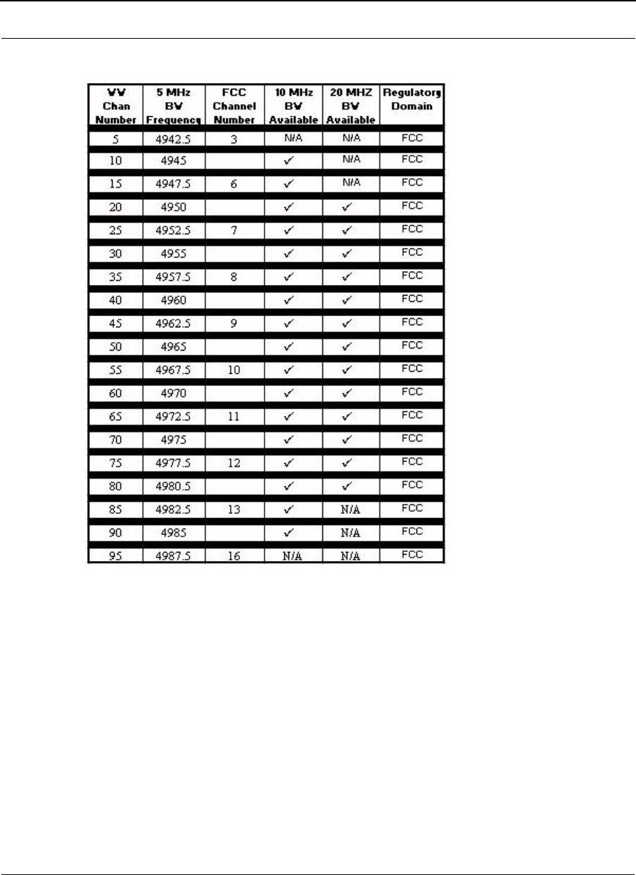
SPEEDLAN 9200 User Guide Part # 34357-MNL Rev. B
F-3
4.9 GHz Channel Center Frequencies vs. Channel Bandwidth

Part # 34357-MNL Rev. B SPEEDLAN 9200 User Guide
F-4

SPEEDLAN 9200 User Guide Part # 34357-MNL Rev. B
Product License Agreement
It is important for users of Wave Wireless hardware and software to take time to read this License Agreement
associated with this software PRIOR TO ITS USE. The Customer or Reseller has paid a License fee to Wave
Wireless for use of this software on one router. This License does not extend to any copyrights to the program
nor does it license use of the program on more than one router nor to make copies of the program for
distribution or resale. A product registration card is included with the product manual. Please complete the card
within 10 days of receipt of the software/hardware and return it to Wave Wireless. Registration is required for
warranty service, technical support and notification of product updates and revisions.
The Customer or Reseller is granted a non-exclusive License to use the licensed program on a single router
subject to the terms and conditions as set forth in this agreement. The Customer or Reseller may not copy, modify
or transfer the reference manual or other documentation or any copy thereof except as expressly provided in this
agreement.
The Copyright and all intellectual/industrial rights of this program and associated material remain the property
of Wave Wireless. THE CUSTOMER OR RESELLER MAY NOT USE, COPY, SUBLICENSE, ASSIGN OR
TRANSFER THE LICENSED MATERIALS OR ANY COPIES THEREOF IN WHOLE OR IN PART,
EXCEPT AS EXPRESSLY PROVIDED IN THIS LICENSE AGREEMENT. The Customer or Reseller shall
not reverse assemble or reverse compile the Licensed product or any copy thereof in whole or in part.
Software License Agreement
The installation and use of this SOFTWARE indicates your understanding and acceptance of the following terms
and conditions. This license shall supersede any verbal or prior written, statement or agreement to the contrary.
If you do not understand or accept these terms, or your local regulations prohibit “after sale” license
agreements or limited disclaimers, you must cease and desist using this product immediately.
The following terms govern your use of the enclosed Software:
License Grant
Wave Wireless (hereafter referred to as Wave Wireless) grants you a license to Use one copy of the Software on
one single-user PC, notebook, or laptop computer. It may not be installed on multiple devices and may not be
shared by more than one individual while in use on a single device. “Use” means storing, loading, installing,
executing or displaying the Software. You may not modify the Software or disable any licensing or control
features of the Software. Uses of this software other than those expressly defined herein are forbidden. Wave
Wireless does not provide support for, nor will it accept return of, this Software if it is used in any manner other
than those outlined here.
Ownership
The Software is owned and copyrighted by Wave Wireless or its third party suppliers. Your license confers no
title or ownership in the Software and is not a sale of any rights, other than the limited right of Use defined
above, in the Software. Wave Wireless and Wave Wireless’s third party suppliers may protect their rights in the

Part # 34357-MNL Rev. B SPEEDLAN 9200 User Guide
event of any violation of these License Terms.
Copies and Adaptations
You may only make copies or adaptations of the Software for archival purposes or when copying or adaptation is
an essential step in the authorized Use of the Software. You must reproduce all copyright notices in the original
Software on all copies or adaptations. You may not copy the Software onto any bulletin board or similar system.
No Disassembly or Decryption
You may not disassemble or decompile the Software unless Wave Wireless’s express prior written consent is
obtained except in those jurisdictions where Wave Wireless’s consent is not required for disassembly or
decompilation. Upon request, you will provide Wave Wireless with reasonably detailed information regarding
any disassembly or decompilation. You may not decrypt the Software for any reason.
Transfer
Your license will automatically terminate upon any transfer of the Software or equipment containing the
Software. Upon transfer, you must deliver the Software, including any copies and related documentation, to the
transferee. The transferee must accept these License Terms as a condition to the transfer.
Termination
Wave Wireless may terminate your license upon notice for failure to comply with any of these License Terms.
Upon termination, you must immediately destroy the Software, together with all copies, adaptations and merged
portions in any form.
Export Restriction
You agree that you will not export or re-export the PRODUCT in any form without the appropriate government
licenses. Your failure to comply with this provision is a material breach of this AGREEMENT.
U.S. Government Restricted Rights
The Software and documentation have been developed entirely at private expense and are provided as
“Commercial Computer Software” or “restricted computer software”. They are delivered and licensed as
“commercial computer software” as defined in DFARS 252.227-7013 (Oct 1988), DFARS 252.211-7015 (May
1991) or DFARS 252.227-7014 (Jun 1995), as a “commercial item” as defined in FAR 2.101 (a), or as
“Restricted computer software” as defined in FAR 52.227-19 (Jun 1987) (or any equivalent agency regulation
or contract clause), whichever is applicable. You have only those rights provided for such Software and
Documentation by the applicable FAR or DFARS clause or the Wave Wireless standard software agreement for
the product.
Wave Wireless LIMITED WARRANTY STATEMENT
1.Wave Wireless warrants to you, the end-user customer, that Wave Wireless hardware, software, accessories
and supplies, will be free from material defects in materials and workmanship for one year after the date of pur-
chase. If Wave Wireless receives notice of such defects during the warranty period, Wave Wireless will, at its
option, either repair or replace products which prove to be defective.

SPEEDLAN 9200 User Guide Part # 34357-MNL Rev. B
2. Wave Wireless does not warrant that the operation of Wave Wireless products will be uninterrupted or error
free. Wave Wireless products may contain remanufactured parts equivalent to new in performance or may have
been subject to incidental use.
3. The limited Warranty does not apply to defects resulting from (a) improper or inadequate maintenance or cal-
ibration, (b) software, interfacing, parts or supplies not supplied by Wave Wireless, (c) unauthorized specifica-
tions for the product, or (d) improper site preparation or maintenance.
4. ANY IMPLIED WARRANTY OF MERCHANTABILITY OR FITNESS FOR A PARTICULAR PURPOSE IS
LIMITED TO THE DURATION OF THE EXPRESS WARRANTY SET FORTH ABOVE. Some states or prov-
inces do not allow limitations on the duration of an implied warranty, so the above limitation or exclusion might
not apply to you. This warranty gives you specific legal rights and you might also have other rights that vary
from state to state, or province to province.
5. THE REMEDIES IN THIS WARRANTY STATEMENT ARE YOUR SOLE AND EXCLUSIVE REMEDIES.
EXCEPT AS INDICATED ABOVE, IN NO EVENT WILL Wave Wireless BE LIABLE FOR LOSS OF DATA OR
FOR DIRECT, SPECIAL, INCIDENTAL, CONSEQUENTIAL (INCLUDING LOST PROFIT), OR OTHER
DAMAGE, WHETHER BASED IN CONTRACT, TORT, OR OTHERWISE. Some states or provinces do not
allow the exclusion or limitation of incidental or consequential damages, so the above limitation or exclusion
may not apply to you.
Return Policies and Warranties
Initial One Year Warranty Term
Each Wave Wireless product is warranted against defects in material and workmanship for a period of one year
from date of shipment. During the warranty period Wave Wireless will, at its option, repair or replace products
that prove to be defective.
If equipment fails, the Customer or Reseller shall notify Wave Wireless and request a Return Material
Authorization (RMA) number. For warranty service or repair, this product must be returned to Wave Wireless.

Part # 34357-MNL Rev. B SPEEDLAN 9200 User Guide
All returns to Wave Wireless MUST have a valid RMA number written clearly on the outside of the box or the
shipment will be refused. The buyer shall pay all return shipping charges during the one-year warranty.
Return for Credit
All returns to Wave Wireless MUST have a valid RMA number written clearly on the outside of the box or the
shipment will be refused. No returns for credit after 30 days will be approved. Products must be returned
undamaged and in original packaging and will be subject to a minimum 20% restocking/refurbishing fee. Return
freight charges must be prepaid. At the option of Wave Wireless, products may be returned for repair or
replaced provided the goods have not been modified or repair attempted by someone other than Wave Wireless.
Limitation of Warranty
The foregoing warranty shall not apply to defects resulting from improper or inadequate maintenance by the
buyer, buyer supplied interfacing, unauthorized modification or misuse, operation outside of the environmental
specifications for the product, or improper site preparation or maintenance. Systems must be protected from
electrical brownouts and surges by a quality UPS such as an APC Smart brand or Tripp Lite Omni or similar, or
warranty shall be null and void. Warranties do not apply to any product that has been (i) altered, except
expressly approved by Wave Wireless in accordance with its instructions, (ii) damaged by improper electrical
power or environment, abuse, misuse, accident, or negligence. Repairs in the case of damage from "acts of God"
are covered on a time and materials basis.
THE FOREGOING WARRANTIES ARE EXCLUSIVE REMEDIES AND ARE IN LIEU OF ALL OTHER
WARRANTIES, EXPRESS OR IMPLIED, INCLUDING, WITHOUT LIMITATION, ANY WARRANTY OF
MERCHANTABILITY OR FITNESS FOR A PARTICULAR PURPOSE.
No statement, including, without limitation, representations regarding capacity, suitability for use or
performance of products, whether made by Wave Wireless employees or otherwise, shall be deemed to be a
warranty by Wave Wireless for any purpose or give rise to any liability for Wave Wireless unless expressly
contained in writing. Resellers will have complete responsibility and liability for performance of its agreements
with its customers and Resellers shall indemnify and hold Wave Wireless harmless from and against all
liability arising out of such agreements.
Wave Wireless warrants that the firmware for use with the unit will execute its programming instructions when
properly installed on the unit. Wave Wireless does not warrant that the operation of the unit or firmware will be
uninterrupted or error-free. Wave Wireless shall not be obligated to remedy any software defect that cannot be
repeated.
Wave Wireless is not responsible for equipment non-performance due to outside radio interference caused by
any source.
Exclusive Remedies
The remedies provided herein are the buyer's sole and exclusive remedies. Wave Wireless shall not be liable for
any direct, indirect, special, incidental or consequential damages, whether based on contract, tort or any legal
theory.