Wave Wireless VOICEXTENDER User Manual VX Manual
Wave Wireless Corporation VX Manual
UserManual.wiki
>
Wave Wireless
>
VOICEXTENDER User Manual
VX Manual
Navigation menu
Upload a User Manual
Namespaces
Wiki Guide
HTML
PDF
Info
Views
User Manual
Discussion / Help
Navigation
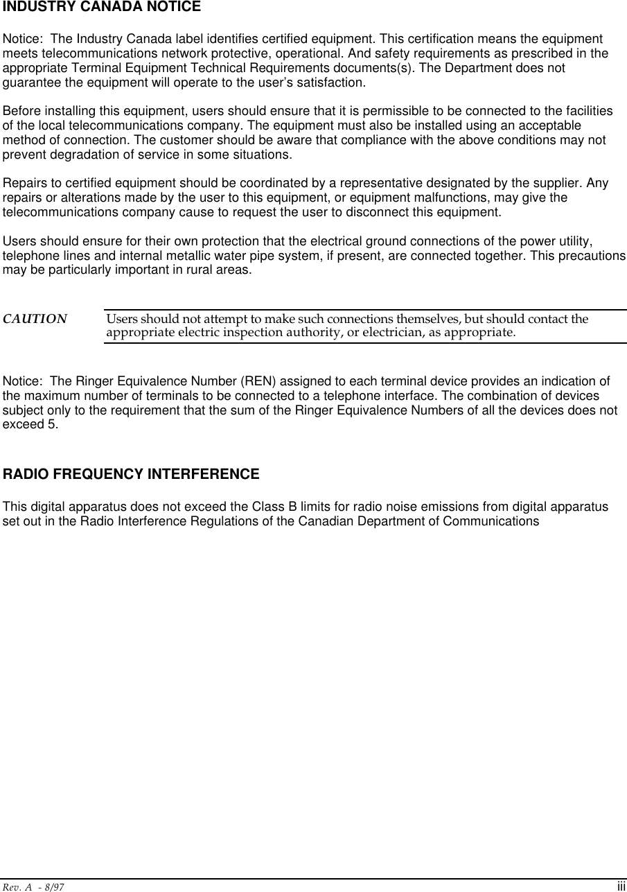
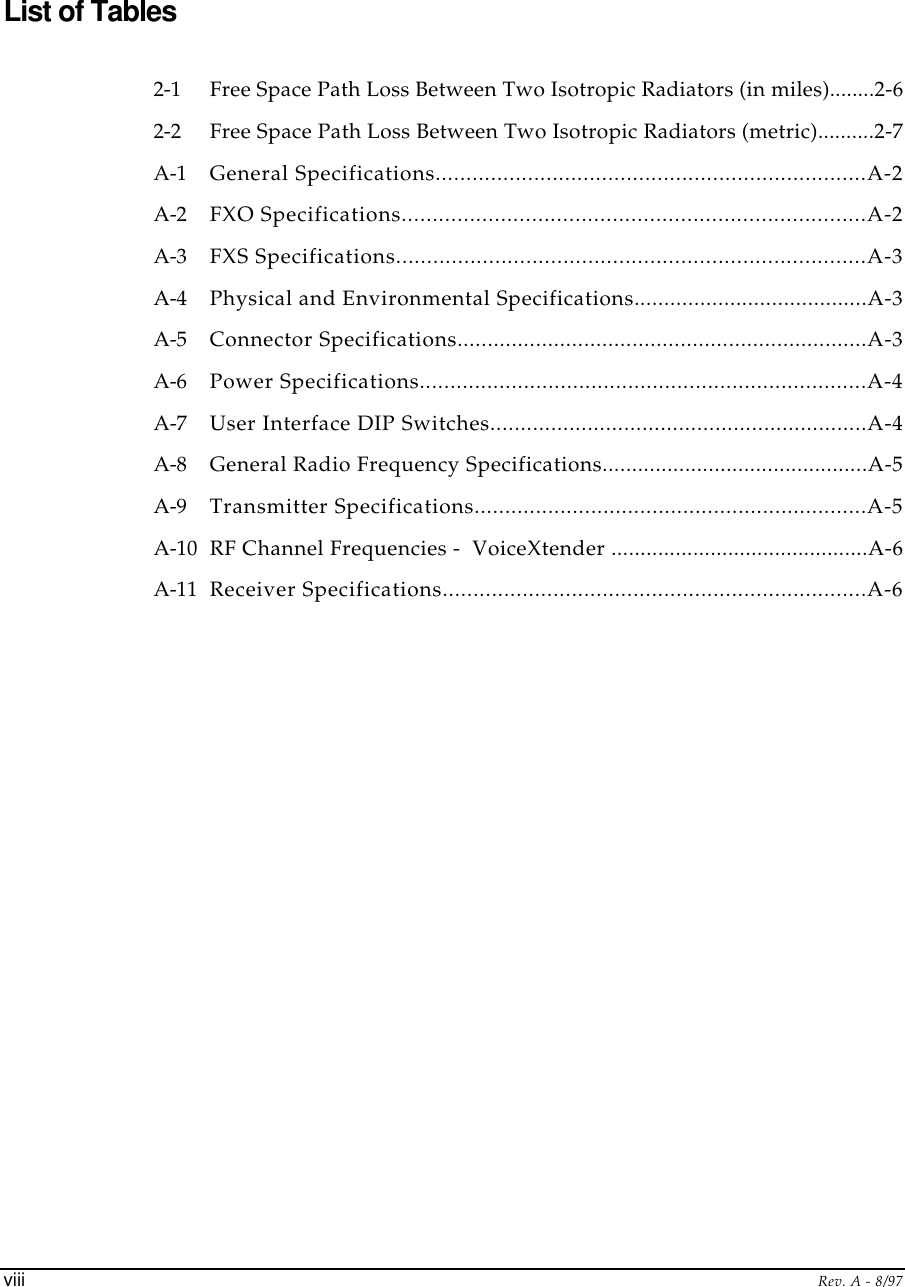
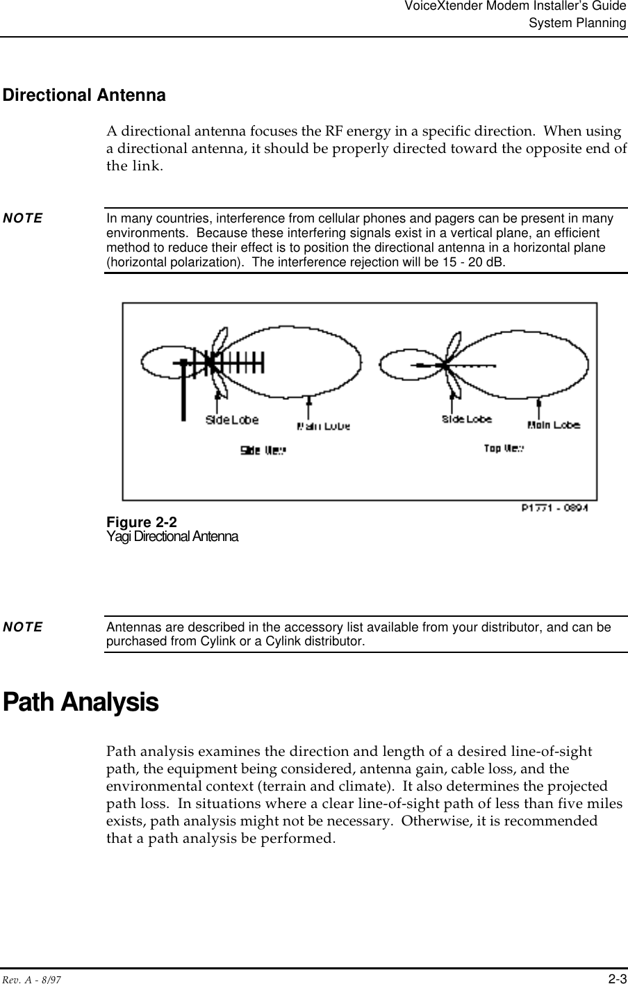
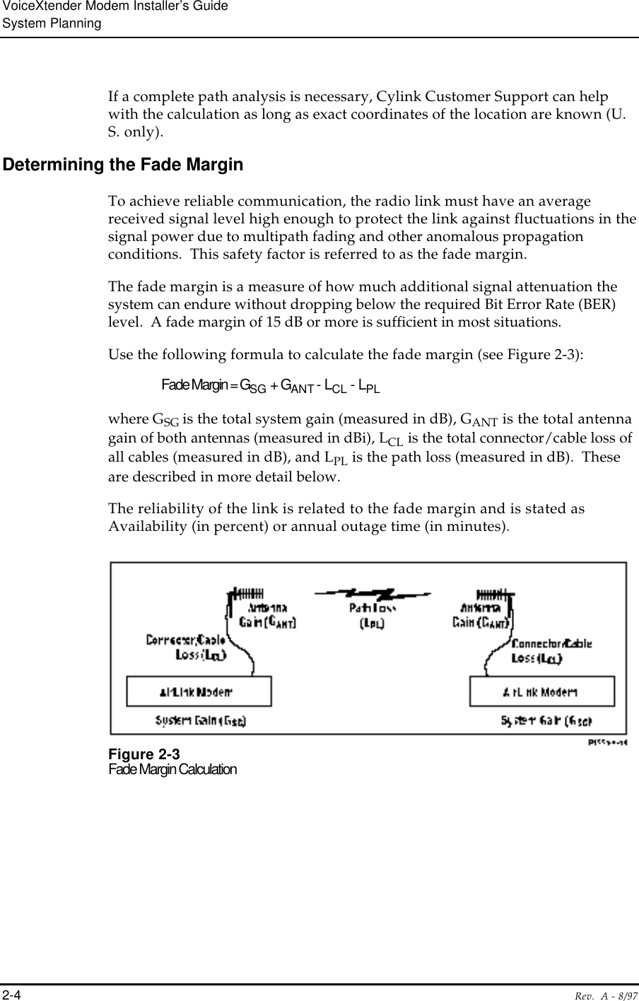
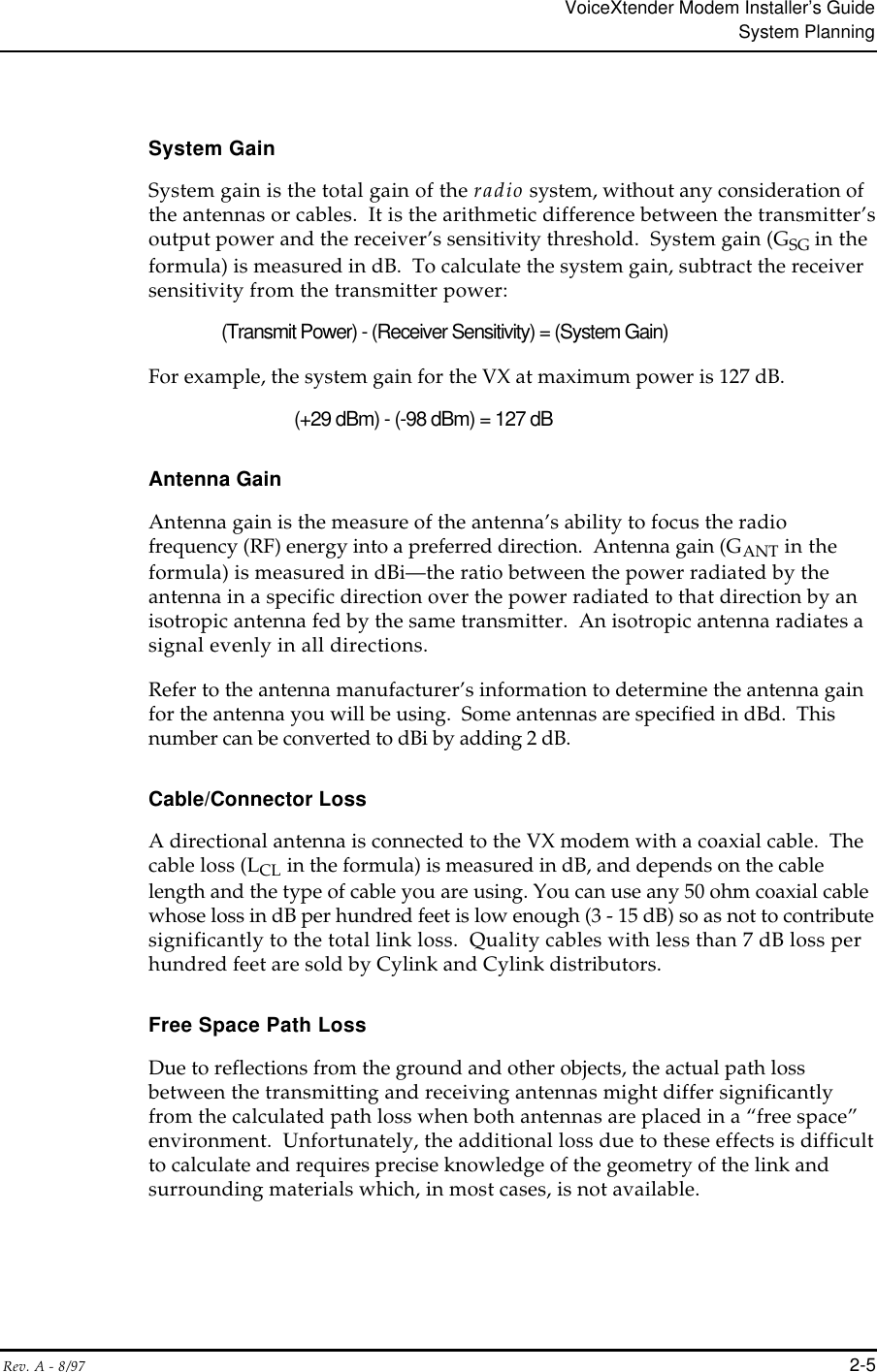
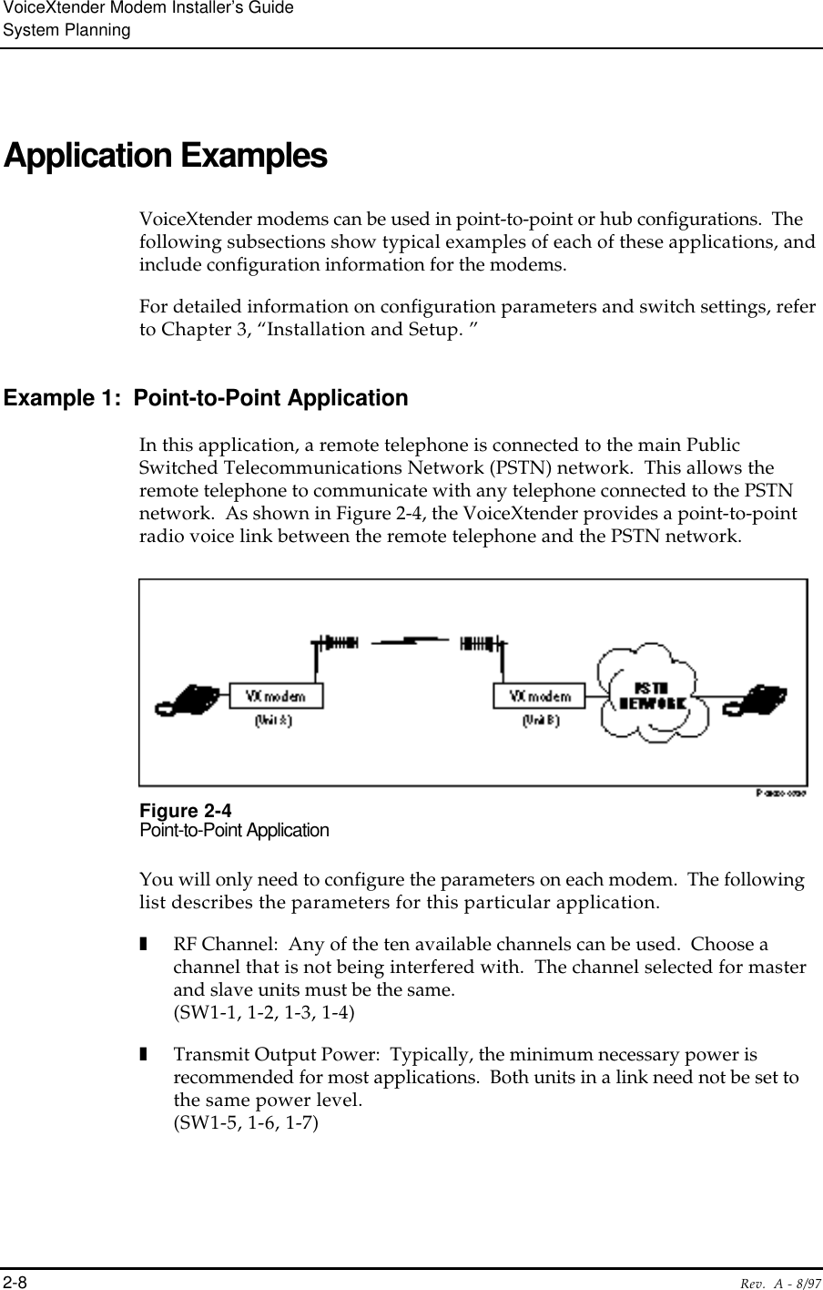
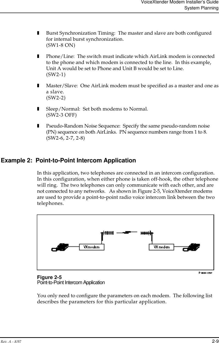
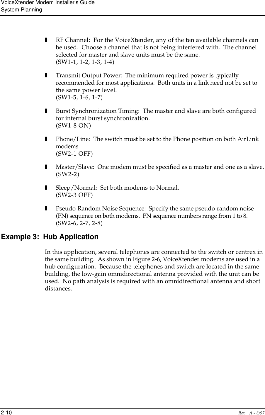
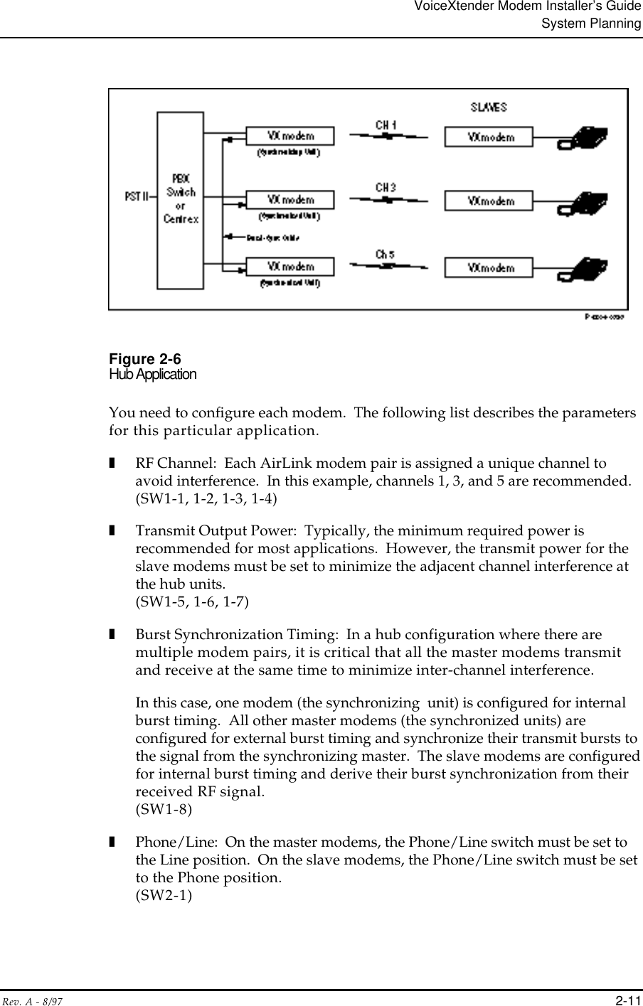
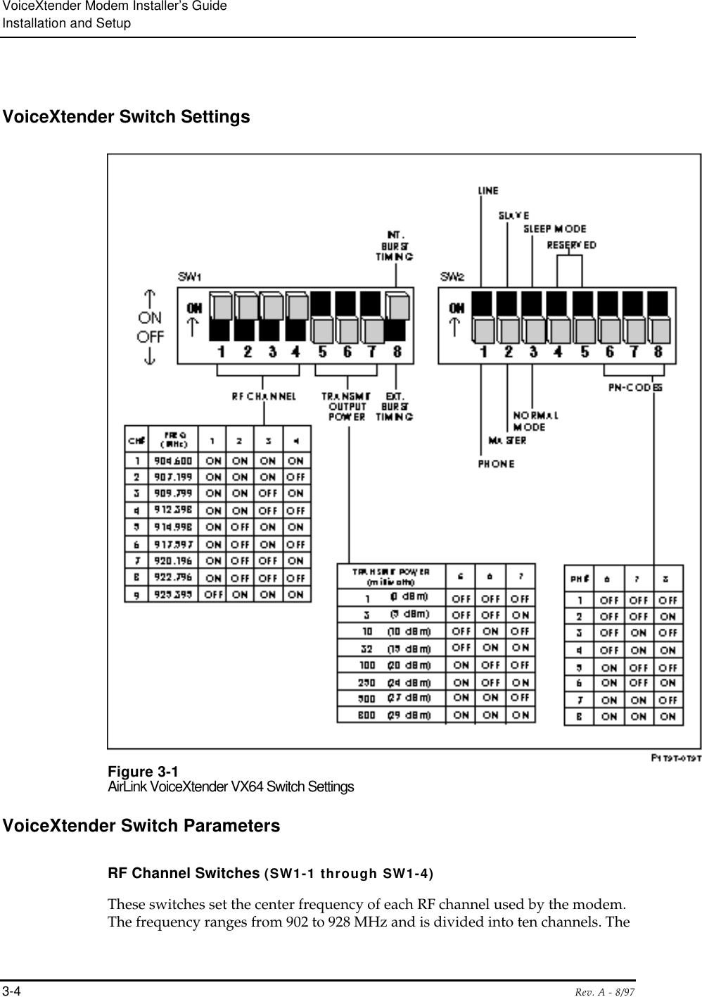
![VoiceXtender Modem Installer’s GuideSystem Planning2-6 Rev. A - 8/97Typically, the largest contributor to “link loss” is the loss of power as thesignal travels through space. This contribution, called Free Space Path Loss,can be easily calculated as follows: To determine the free space path loss,determine the distance between the VX modems for your application and referto Table 2-1, or use the following formula:attenuation in dB = [96. 6 + 20 LOG (distance in miles) + 20 LOG (frequency in GHz)]Table 2-1Free Space Path Loss Between Two Isotropic RadiatorsDistance(Miles) Path Loss@ 915 MHz(L-Band)1 96 dB2 102 dB3 105 dB4 108 dB5 110 dB6 111 dB7 113 dB8 114 dB9 115 dB10 116 dB15 120 dB20 123 dB25 125 dB30 126 dB](https://usermanual.wiki/Wave-Wireless/VOICEXTENDER/User-Guide-28656-Page-26.png)
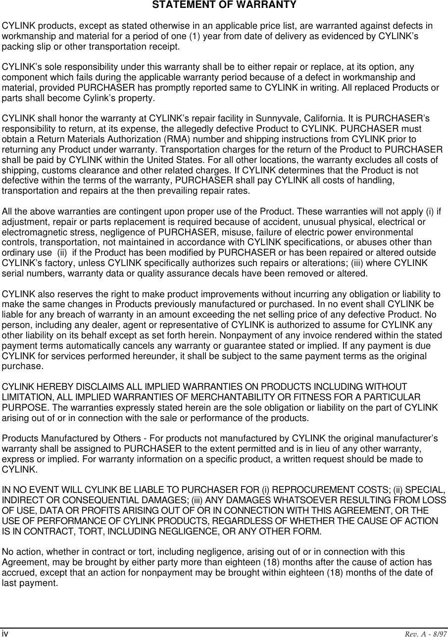
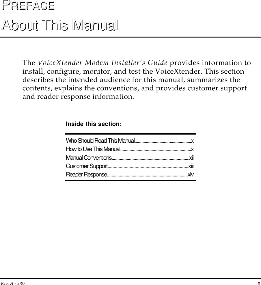
![VoiceXtender Modem Installer’s GuideSystem PlanningRev. A - 8/97 2-7Table 2-2Free Space Path Loss Between Two Isotropic RadiatorsDistance(kilometers) Path Loss@ 915 MHz(L-Band)1 92 dB2 98 dB3 101 dB4 104 dB5 106 dB6 107 dB7 109 dB8 110 dB9 111 dB10 112 dB15 115 dB20 118 dB25 120 dB30 121 dB35 123 dB40 124 dB50 126 dBNOTE The calculation for attenuation using kilometers is:attenuation in dB = [92. 4 + 20 LOG (distance in kilometers) + 20 LOG (frequency in GHz)]](https://usermanual.wiki/Wave-Wireless/VOICEXTENDER/User-Guide-28656-Page-27.png)