Wave Wireless VOICEXTENDER User Manual VX Manual
Wave Wireless Corporation VX Manual
VX Manual

Installation Guide
Cylink VoiceXtender Modem
Package: 81229-00A
August 1997
¤
CYLINK CORPORATION
910 Hermosa Court
Sunnyvale, California 94086, USA
(408) 735-5800
CYLINK LIMITED U.K.
Tel: +44-1256-841919
Fax: +44-1256-24156
CYLINK CORPORATION (Singapore)
Tel: +65-297-6196
Fax: +65-297-6195
CYLINK CORPORATION (New Delhi)
Tel: +91-11-617-6913
Fax: +91-617-9529
CYLINK CORPORATION (Beijing)
Tel: +81-10-6467-1905
Fax: +86-10-6467-1906
CYLINK CORPORATION (Karachi)
Tel: +92-21-5840743
Fax: +92-21-5840727
CYLINK CUSTOMER SUPPORT
1-800-545-6608 (USA - California)
1-800-814-5587 (USA - New Jersey)
1-408-735-5822 (Internaltional - California)
1-201-333-3400 (International - New Jersey)
+44-1256-58122 (Cylink Limited - U.K.)
HOME

Rev. A - 8/97 i
COPYRIGHT 1994 - 1997 Cylink Corporation, World Rights Reserved
Cylink Corporation provides this document “as is,” without warranty of any kind, either expressed or implied,
including, but not limited to, the implied warranties of merchantability and fitness for a particular purpose.
Cylink Corporation may make improvements and changes to the product described in this Manual at any
time and without notice. Cylink Corporation assumes no responsibility for its use, nor any infringements of
patents or other rights of third parties that would result.
This document could contain technical inaccuracies or typographical errors. Periodic changes are made to
the information contained herein; these changes will be incorporated into new editions of the Manual.
No part of this publication may be stored in a retrieval system, transmitted, or reproduced in any way,
including, but not limited to, photocopy, photograph, magnetic or other records, without the prior written
permission of Cylink Corporation.
VoiceXtender is a trademark and CYLINK® is a registered trademark of the Cylink Corporation.
PRODUCT COMPATIBILITY
While every effort has been made to verify operation of this product with many different communications
products and networks, Cylink Corporation makes no claim of compatibility between its products and other
vendors’ equipment. It is assumed that users have thoroughly evaluated this product’s performance in the
communications environment in which it will be used.
SAFETY
The following general safety precautions must be observed during all phases of operation and service of this
product. Failure to comply with these precautions or with specific warnings elsewhere in this Manual willfully
violates standards of design, manufacture, and intended use of the product. Cylink Corporation assumes no
liability for the customer's failure to comply with these requirements.
This product must be grounded. In the event of a short circuit, grounding reduces the risk of electrical shock
by providing an escape wire for the current.
The product's AC power cord ends in a three-pole grounding plug. Do not use a three-pole to two-pole
adapter with the plug. Verify that the outlet you intend to use is properly installed and grounded; the outlet
used must comply with the local electric code.
Do not install or operate this product in the presence of flammable gases or fumes. Operation of any
electrical instrument in such an environment constitutes a definite safety hazard.
No user maintained or adjustable components are present within this product. The covers should not be
removed by anyone other than authorized Cylink service personnel. The potential for electrical shock exists
within the cabinet at all times unless it is unplugged.
Do not install substitute parts or perform any unauthorized modification to the VoiceXtender modems.
Return the product to Cylink Corporation for service and repair to ensure that safety features are
maintained. Prior to returning any product(s) for repair, contact Cylink at the telephone numbers or address
located on the front of this Manual, and obtain a Return Material Authorization (RMA) number.
Changes or modifications not expressly approved by Cylink Corporation can void the user’s authority to
operate the equipment.

ii Rev. A - 8/97
TOWER CONSTRUCTION
Compliance with local zoning and tower construction regulations is recommended when VoiceXtender digital
modem radios require a tower. These regulations generally mandate that permits be obtained before any
tower construction begins. Check with local zoning and aviation authorities for more information.
FCC PART 68 INFORMATION
Federal Communications Commission (FCC) Rules on spread spectrum devices, such as the VoiceXtender,
require that you be notified of the following:
This equipment complies with Part 68 of the FCC Rules. The FCC Part 68 label is located on the bottom of
the enclosure. This label contains the FCC Registration Number for this equipment. If requested, this
information must be provided to your telephone company.
The REN is useful to determine the quantity of devices you may connect to your telephone line and still have
all of those devices ring when your telephone number is called. In most, but not all areas, the sum of the
RENs of all devices connected to one line should not exceed five (5.0). To be certain of the number of
devices you may connect to your line, as determined by the REN, you should contact your local telephone
company to determine the maximum REN for your calling area.
Connection to the telephone network should be made by using standard modular telephone jacks, type
RJ11C or RJ11W. The RJ11C or RJ11W plug and/or jacks used must comply with FCC Part 68 rules.
If this telephone equipment causes harm to the telephone network, the telephone company will notify you in
advance that temporary discontinuance of service may be required. But if advance notice isn’t practical, the
telephone company will notify the customer as soon as possible. Also, you will be advised of your right to file
a complaint with the FCC if you believe it is necessary.
The telephone company may make changes in it’s facilities, equipment, operations or procedures that could
affect the proper functioning of your equipment. If they do, you will be notified in advance in order for you to
make necessary modifications to maintain uninterrupted service.
This equipment may not be used on coin service provided by the telephone company. Connection to party
lines is subject to state tariffs.
REPAIR INSTRUCTION
Repairs to this equipment can only be made by the manufacturer or its authorized agents. If this equipment
is causing harm to the telephone network, the telephone company may request that it be unplugged from the
modular outlet until the problem has been corrected. To obtain repair service or warranty information
contact:
Cylink Corporation
1350 Bordeaux Drive
Sunnyvale, CA 94089
Attn: Repair and Return Department
1-800-545-6608
FCC regulations require that this device be professionally installed by a person knowledgeable in electronics
and trained in the correct installation of this device.
All interface cables must be shielded.
This device complies with Part 15 of FCC Rules. Operation is subject to the following two conditions:
(1) this device may not cause harmful interference, and (2) this device must accept any interference
received, including interference that may cause undesired operation.

Rev. A - 8/97 iii
INDUSTRY CANADA NOTICE
Notice: The Industry Canada label identifies certified equipment. This certification means the equipment
meets telecommunications network protective, operational. And safety requirements as prescribed in the
appropriate Terminal Equipment Technical Requirements documents(s). The Department does not
guarantee the equipment will operate to the user’s satisfaction.
Before installing this equipment, users should ensure that it is permissible to be connected to the facilities
of the local telecommunications company. The equipment must also be installed using an acceptable
method of connection. The customer should be aware that compliance with the above conditions may not
prevent degradation of service in some situations.
Repairs to certified equipment should be coordinated by a representative designated by the supplier. Any
repairs or alterations made by the user to this equipment, or equipment malfunctions, may give the
telecommunications company cause to request the user to disconnect this equipment.
Users should ensure for their own protection that the electrical ground connections of the power utility,
telephone lines and internal metallic water pipe system, if present, are connected together. This precautions
may be particularly important in rural areas.
CAUTION Users should not attempt to make such connections themselves, but should contact the
appropriate electric inspection authority, or electrician, as appropriate.
Notice: The Ringer Equivalence Number (REN) assigned to each terminal device provides an indication of
the maximum number of terminals to be connected to a telephone interface. The combination of devices
subject only to the requirement that the sum of the Ringer Equivalence Numbers of all the devices does not
exceed 5.
RADIO FREQUENCY INTERFERENCE
This digital apparatus does not exceed the Class B limits for radio noise emissions from digital apparatus
set out in the Radio Interference Regulations of the Canadian Department of Communications

iv Rev. A - 8/97
STATEMENT OF WARRANTY
CYLINK products, except as stated otherwise in an applicable price list, are warranted against defects in
workmanship and material for a period of one (1) year from date of delivery as evidenced by CYLINK’s
packing slip or other transportation receipt.
CYLINK’s sole responsibility under this warranty shall be to either repair or replace, at its option, any
component which fails during the applicable warranty period because of a defect in workmanship and
material, provided PURCHASER has promptly reported same to CYLINK in writing. All replaced Products or
parts shall become Cylink’s property.
CYLINK shall honor the warranty at CYLINK’s repair facility in Sunnyvale, California. It is PURCHASER’s
responsibility to return, at its expense, the allegedly defective Product to CYLINK. PURCHASER must
obtain a Return Materials Authorization (RMA) number and shipping instructions from CYLINK prior to
returning any Product under warranty. Transportation charges for the return of the Product to PURCHASER
shall be paid by CYLINK within the United States. For all other locations, the warranty excludes all costs of
shipping, customs clearance and other related charges. If CYLINK determines that the Product is not
defective within the terms of the warranty, PURCHASER shall pay CYLINK all costs of handling,
transportation and repairs at the then prevailing repair rates.
All the above warranties are contingent upon proper use of the Product. These warranties will not apply (i) if
adjustment, repair or parts replacement is required because of accident, unusual physical, electrical or
electromagnetic stress, negligence of PURCHASER, misuse, failure of electric power environmental
controls, transportation, not maintained in accordance with CYLINK specifications, or abuses other than
ordinary use (ii) if the Product has been modified by PURCHASER or has been repaired or altered outside
CYLINK’s factory, unless CYLINK specifically authorizes such repairs or alterations; (iii) where CYLINK
serial numbers, warranty data or quality assurance decals have been removed or altered.
CYLINK also reserves the right to make product improvements without incurring any obligation or liability to
make the same changes in Products previously manufactured or purchased. In no event shall CYLINK be
liable for any breach of warranty in an amount exceeding the net selling price of any defective Product. No
person, including any dealer, agent or representative of CYLINK is authorized to assume for CYLINK any
other liability on its behalf except as set forth herein. Nonpayment of any invoice rendered within the stated
payment terms automatically cancels any warranty or guarantee stated or implied. If any payment is due
CYLINK for services performed hereunder, it shall be subject to the same payment terms as the original
purchase.
CYLINK HEREBY DISCLAIMS ALL IMPLIED WARRANTIES ON PRODUCTS INCLUDING WITHOUT
LIMITATION, ALL IMPLIED WARRANTIES OF MERCHANTABILITY OR FITNESS FOR A PARTICULAR
PURPOSE. The warranties expressly stated herein are the sole obligation or liability on the part of CYLINK
arising out of or in connection with the sale or performance of the products.
Products Manufactured by Others - For products not manufactured by CYLINK the original manufacturer’s
warranty shall be assigned to PURCHASER to the extent permitted and is in lieu of any other warranty,
express or implied. For warranty information on a specific product, a written request should be made to
CYLINK.
IN NO EVENT WILL CYLINK BE LIABLE TO PURCHASER FOR (i) REPROCUREMENT COSTS; (ii) SPECIAL,
INDIRECT OR CONSEQUENTIAL DAMAGES; (iii) ANY DAMAGES WHATSOEVER RESULTING FROM LOSS
OF USE, DATA OR PROFITS ARISING OUT OF OR IN CONNECTION WITH THIS AGREEMENT, OR THE
USE OF PERFORMANCE OF CYLINK PRODUCTS, REGARDLESS OF WHETHER THE CAUSE OF ACTION
IS IN CONTRACT, TORT, INCLUDING NEGLIGENCE, OR ANY OTHER FORM.
No action, whether in contract or tort, including negligence, arising out of or in connection with this
Agreement, may be brought by either party more than eighteen (18) months after the cause of action has
accrued, except that an action for nonpayment may be brought within eighteen (18) months of the date of
last payment.

Rev. A - 8/97 v
Table of Contents
Preface About This Manual............................................................................ix
Who Should Read This Manual................................................................x
How to Use This Manual..........................................................................x
Manual Conventions................................................................................xi
Customer Support....................................................................................xi
Reader Response...................................................................................xii
Chapter 1 Introduction................................................................................1-1
Product Overview.................................................................................1-2
Features..........................................................................................1-3
Applications.........................................................................................1-3
Front Panel Description.........................................................................1-4
Rear Panel Description..........................................................................1-5
Chapter 2 System Planning.........................................................................2-1
Introduction..........................................................................................2-2
Antenna Options...................................................................................2-2
Omnidirectional Antenna................................................................2-2
Directional Antenna........................................................................2-3
Path Analysis.......................................................................................2-3
Determining the Fade Margin..........................................................2-4
System Gain..............................................................................2-4
Antenna Gain............................................................................2-5
Cable/Connector Loss................................................................2-5
Free Space Path Loss.................................................................2-5
Application Examples...........................................................................2-7
Example 1: Point-to-Point Application............................................2-7
Example 2: Point-to-Point Intercom Application..............................2-9
Example 3: Hub Application.........................................................2-11
Chapter 3 Installation and Setup................................................................3-1
System Setup........................................................................................3-2
Switch Settings.....................................................................................3-2
VoiceXtender Switch Settings.........................................................3-3
VoiceXtender Switch Parameters....................................................3-4

vi Rev. A - 8/97
Cabling the Modem...............................................................................3-6
Installing the Antenna....................................................................3-6
Connecting the Line/Phone Interface................................................3-7
Cabling a Hub Application..............................................................3-8
Connecting the Power......................................................................3-9
System Startup...................................................................................3-10
Directional Antenna Alignment.....................................................3-10
Adjusting the Audio Receive Level................................................3-13
Chapter 4 Troubleshooting..........................................................................4-1
Operational Problems...........................................................................4-2
Maintenance.........................................................................................4-3
Appendix A Specifications........................................................................A-1
General Specifications.........................................................................A-2
Interface Specifications........................................................................A-7
Appendix B Worksheets............................................................................B-1
Appendix C Glossary.................................................................................D-1
Index...................................................................................................Index-1

Rev. A - 8/97 vii
List of Figures
1-1 VoiceXtender....................................................................................1-2
1-2 VoiceXtender - Front Panel................................................................1-4
1-3 VoiceXtender - Rear Panel.................................................................1-5
2-1 Omnidirectional Antenna...................................................................2-2
2-2 Yagi Directional Antenna...................................................................2-3
2-3 Fade Margin Calculation....................................................................2-4
2-4 Point-to-Point Application.................................................................2-8
2-5 Point-to-Point Intercom Application...................................................2-9
2-6 Hub Application..............................................................................2-11
3-1 VoiceXtender Switch Settings............................................................3-3
3-2 Connecting the Low-Gain Omnidirectional Antenna............................3-6
3-3 Connecting the Line and Phone Interface.............................................3-7
3-4 Burst Synchronization Cabling...........................................................3-8
3-5 Connecting the Power.........................................................................3-9
3-6 Antenna Alignment Flow Chart........................................................3-12
3-7 Volume Adjustment..........................................................................3-13
A-1 Rear Panel RJ11 Connector.................................................................A-7
A-2 Rear Panel Power Input Connector (Female DIN)................................A-7

viii Rev. A - 8/97
List of Tables
2-1 Free Space Path Loss Between Two Isotropic Radiators (in miles)........2-6
2-2 Free Space Path Loss Between Two Isotropic Radiators (metric)..........2-7
A-1 General Specifications......................................................................A-2
A-2 FXO Specifications...........................................................................A-2
A-3 FXS Specifications............................................................................A-3
A-4 Physical and Environmental Specifications.......................................A-3
A-5 Connector Specifications....................................................................A-3
A-6 Power Specifications.........................................................................A-4
A-7 User Interface DIP Switches..............................................................A-4
A-8 General Radio Frequency Specifications.............................................A-5
A-9 Transmitter Specifications................................................................A-5
A-10 RF Channel Frequencies - VoiceXtender ............................................A-6
A-11 Receiver Specifications.....................................................................A-6

Rev. A - 8/97 ix
P
PREFACE
REFACE
About This Manual
About This Manual
The VoiceXtender Modem Installer’s Guide provides information to
install, configure, monitor, and test the VoiceXtender. This section
describes the intended audience for this manual, summarizes the
contents, explains the conventions, and provides customer support
and reader response information.
Inside this section:
Who Should Read This Manual..................................................x
How to Use This Manual.............................................................x
Manual Conventions...................................................................xii
Customer Support..................................................................xiii
Reader Response.....................................................................xiv

AirLink VoiceXtender Modem Installer’s Guide
Preface
xRev. A- 8/97
Who Should Read This Manual
This manual is for people who will install, configure, and operate Cylink’s
VoiceXtender modems. The manual provides general guidelines on how to
prepare for and configure the AirLink modems for use in a typical environment,
including system planning, antenna options, and path analysis. We assume
that you have experience with and an understanding of the concepts underlying
telecommunications systems, as well as some familiarity with radio equipment.
You must also have knowledge of all radio frequency and electrical safety
practices and regulations that apply to the installation site.
How to Use This Manual
Each of the chapters and appendices in this manual begin with an introduction
to the contents of that portion of the manual. Before beginning the installation
process, you should read the introductions to each chapter so that you know
what each portion provides.
When you come to a procedure, skim through the entire procedure before
performing the step-by-step instructions. By doing this, you can prepare with
the appropriate information, equipment, and tools.
The information in this manual is organized according to the sequence of tasks
necessary to plan for unpacking, installing, and configuring, as well as operating
and maintaining the VoiceXtender modem.

AirLink VoiceXtender Modem Installer’s Guide
Preface
Rev. A - 8/97 xi
Title Description
Chapter 1
Introduction Provides a general description of VoiceXtender modems,
including features and front and rear panel information.
Chapter 2
System Planning Provides information on configuration planning, path
analysis, and typical applications.
Chapter 3
Installation and Setup Provides instructions on how install modems, configure
the DIP switches, cable the equipment, and align the
antenna.
Chapter 4
Troubleshooting Provides information on troubleshooting and possible
operational problems when using modems.
Appendix A
Specifications Provides information on general specifications and radio
interface specifications.
Appendix B
Worksheets Assists in the system planning process by providing a
means to note VoiceXtender configuration settings and
maintain a record of the settings.
Appendix C
Glossary Provides definitions for the terms commonly used
throughout the manual.
Index Provides a quick reference to assist you in locating
important terms in the manual.

AirLink VoiceXtender Modem Installer’s Guide
Preface
xii Rev. A- 8/97
Manual Conventions
The procedures and instructions in this manual use the following conventions:
❚The two configuration switches on the unit are referred to as SW1 and SW2.
Each switch consists of 8 individual ON/OFF switches that are referred to
as SW1-1, SW1-2, SW2-1, SW2-2, etc.
❚The following notes are used to add information, point to other important
considerations, or alert you to possible risks to you, your equipment, or your
data.
NOTE These standard text notes highlight important or additional information for you to consider.
CAUTION These notes warn you of situations that could result in damage to your equipment or loss
of data if you do not heed the instructions.
WARNING These notes warn you of situations that could endanger your health or safety if you do not
heed the instructions.

AirLink VoiceXtender Modem Installer’s Guide
Preface
Rev. A - 8/97 xiii
Customer Support
If after reading this guide you encounter any trouble installing or using the
VoiceXtender modem, please contact your local distributor. If problems are not
resolved, you can call Cylink’s Customer Service for assistance. The telephone
numbers are:
Domestic (U.S.):
1-800-545-6608 Sunnyvale, CA
International:
1-408-735-5822 Sunnyvale, CA
+65-297-6196 Singapore
+44-1256-841919 United Kingdom
+91-11-301-0090 India
+92-21-215-7264 Pakistan
Domestic and International Customer Service fax:
1-408-735-6641 Sunnyvale, CA
+65-297-6195 Singapore
+44-1256-24156 United Kingdom
+91-11-379-3584 India
+92-21-587-0065 Pakistan
You can also contact Cylink’s Customer Support through the Internet at the
following email address:
support@cylink.com
If you need to return equipment, call Customer Service to obtain a return
material authorization (RMA) number prior to returning the equipment. The
RMA number must be on the outside of the shipping carton. When you call,
please be prepared to provide the unit serial number, software version, and a
detailed description of the problem.

AirLink VoiceXtender Modem Installer’s Guide
Preface
xiv Rev. A- 8/97
Return all equipment to:
Cylink Corporation
1350 Bordeaux Drive
Sunnyvale, CA 94089
Attn: Repair and Return Department
RMA No: xxxxxxxxxx
Reader Response
Cylink’s technical publications department wants its documents to meet your
requirements. To this end, your ideas about the documentation are valuable.
After you have had a chance to read and use the guide, we encourage you to
submit your comments to
Manager, Technical Publications
Cylink Corporation
910 Hermosa Court
Sunnyvale, CA 94086
You can also submit your comments through the Internet at the following
address:
techpubs@cylink.com
Cylink may use or distribute any of the information you supply in any way it
believes appropriate without incurring any obligations whatsoever.

Rev. A - 8/97 1-1
C
CHAPTER
HAPTER 1
1
Introduction
Introduction to the
to the
VoiceXtender
VoiceXtender
This chapter contains an overview of the features and
applications of Cylink’s VoiceXtender modems, and includes
descriptions of the front and rear panels.
Inside this chapter:
Product Overview.................................................................1-2
Applications............................................................................1-3
Front Panel Description.......................................................1-4
Rear Panel Description........................................................1-5
VoiceXtender Installer’s Guide
Introduction
1-2 Rev. A - 8/97
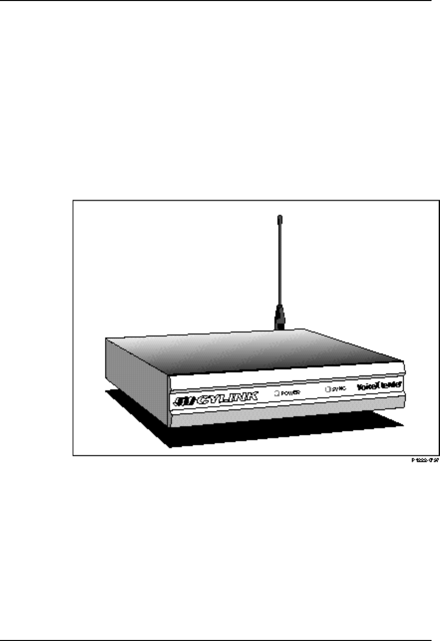
Product Overview
Cylink’s family of modems provide a wireless solution for data and voice
connectivity using spread spectrum technology (902 to 928 MHz frequency band).
VoiceXtender modems support 2-wire voice.
Figure 1-1
VoiceXtender

VoiceXtender Installer’s Guide
Introduction
Rev. A - 8/97 1-3
Features
VoiceXtender (VX) modems provide the following features:
❚ Increased modem data rate to 28.8 Kbps
❚ Enables the maximum performance through a voice modem-CODEX
connection
❚ Caller Number Delivery and Signaling
❚902 to 928 MHz operating frequency
❚Selectable channels
❚Selectable output power
❚Optional omnidirectional or directional antennas
❚Power on and radio synchronization status indicators
❚Hub (several co-located terminals) configurability
❚Adjustable audio receive (ear piece) level.
The VoiceXtender replaces the wired connection between a standard telephone
and the on-premises switch or centrex with a radio link. Both foreign exchange
station (FXS) and foreign exchange office (FXO) loop-start signaling are
supported. The VoiceXtender provides a standard ringer current for the
telephone ringer.
With the Caller Number Delivery feature, modulation is digitized by the VX
64 and converted at the receiving end within the specified three seconds.
Applications
VX modems can be configured for point-to-point applications to provide a radio
link between telephone devices. Several VX modems can be connected in a hub
configuration to allow even greater flexibility in the arrangement of telephone
equipment.
VoiceXtender Installer’s Guide
Introduction
1-4 Rev. A - 8/97
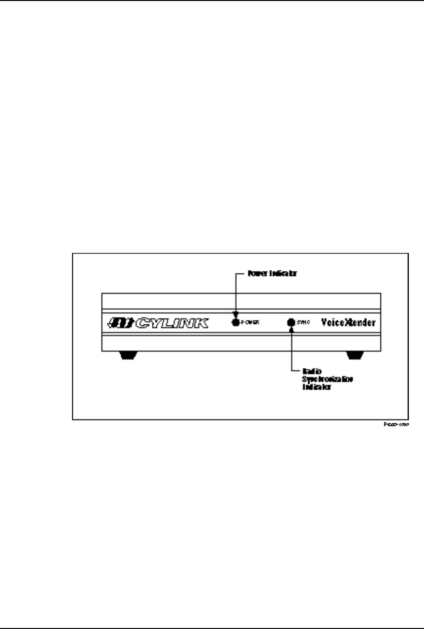
Front Panel Description
The front of the VoiceXtender modem contains two green visual indicators:
❚POWER—this indicator illuminates when the modem is plugged into
the power outlet and is receiving power.
❚SYNC—this indicator illuminates when the channel is ready for
transmission (the RF link is up). When this indicator is flashing, the
RF link is not well established. When this indicator is off, the RF link
is down.
Figure 1-2 shows the front panel of an VoiceXtender modem. For more
information on indicators, refer to the section entitled “System Startup” in
Chapter 3, “Installation and Setup.”
Figure 1-2
VoiceXtender (VX) Modem - Front Panel
VoiceXtender Installer’s Guide
Introduction
Rev. A - 8/97 1-5
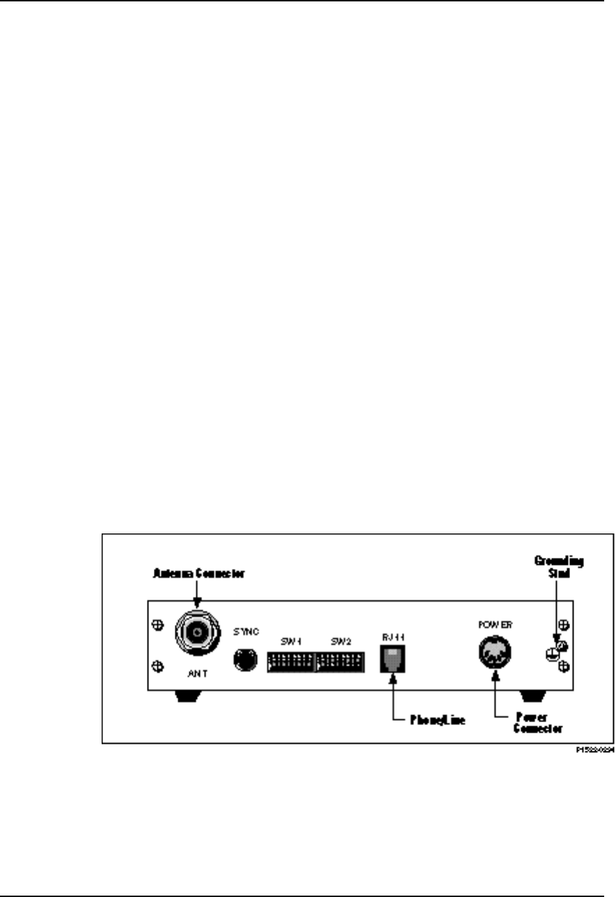
Rear Panel Description
The VoiceXtender modem is easily configured using the configuration switches
located at the rear of the modem. All connections are also located at the rear as
shown in Figure 1-3.
The following list describes the items on the rear panel:
❚Antenna connector (ANT) is a female N-type connector for connection to
either an omnidirectional or directional antenna
❚Female BNC connector for burst synchronization signal (SYNC) to
connect the synchronizing unit to synchronized modems in a hub
configuration or slave unit to master unit in a repeater application
❚Two configuration switches, each consisting of eight individual
ON/OFF switches
❚RJ11-type modular connector for the line or phone connection
❚5-pin female DIN connector for the external power supply
❚System grounding stud
For information on applications, refer to Chapter 2, “System Planning.” For
information on cabling and switch settings, refer to Chapter 3, “Installation and
Setup.” Information on specific cable pin signals can be found in Appendix A,
“Specifications.”
Figure 1-3
VoiceXtender Modem - Rear Panel

Rev. A - 8/97 2-1
C
CHAPTER
HAPTER 2
2
System Planning
System Planning
This chapter contains some general planning requirements and
considerations to prepare for a quick and efficient installation of your
VoiceXtender modems, including antenna options, path analysis, and
sample applications.
Inside this chapter:
Introduction............................................................................2-2
Antenna Options....................................................................2-2
Path Analysis..........................................................................2-3
Application Examples............................................................2-8
VoiceXtender Modem Installer’s Guide
System Planning
2-2 Rev. A - 8/97
Introduction
The installation procedure and effectiveness of the radio link vary depending
upon the following items:
❚Type of antenna used
❚Distances, height, and line-of-sight between the antennas
❚Distance between the modem and antenna.
The following sections provide guidelines on how to prepare for the
installation and successful operation of VoiceXtender (VX) modems, and include
examples of typical applications.
Antenna Options
VX modems can be used with omnidirectional or directional antennas. These
antennas are typically mounted on the roof of a building and are connected to
the VX modem with 50 Ohm coaxial cable.
Omnidirectional Antennas
An omnidirectional antenna is capable of transmitting or receiving signals from
all directions in a horizontal plane, with equal power in each direction. It is
similar to dropping a stone in a pool and seeing rings emanating from the center.
Refer to Figure 2-1.
Figure 2-1
Omnidirectional Antenna
VoiceXtender Modem Installer’s Guide
System Planning
Rev. A - 8/97 2-3
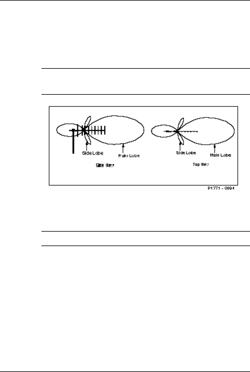
Directional Antenna
A directional antenna focuses the RF energy in a specific direction. When using
a directional antenna, it should be properly directed toward the opposite end of
the link.
NOTE In many countries, interference from cellular phones and pagers can be present in many
environments. Because these interfering signals exist in a vertical plane, an efficient
method to reduce their effect is to position the directional antenna in a horizontal plane
(horizontal polarization). The interference rejection will be 15 - 20 dB.
Figure 2-2
Yagi Directional Antenna
NOTE Antennas are described in the accessory list available from your distributor, and can be
purchased from Cylink or a Cylink distributor.
Path Analysis
Path analysis examines the direction and length of a desired line-of-sight
path, the equipment being considered, antenna gain, cable loss, and the
environmental context (terrain and climate). It also determines the projected
path loss. In situations where a clear line-of-sight path of less than five miles
exists, path analysis might not be necessary. Otherwise, it is recommended
that a path analysis be performed.
VoiceXtender Modem Installer’s Guide
System Planning
2-4 Rev. A - 8/97
If a complete path analysis is necessary, Cylink Customer Support can help
with the calculation as long as exact coordinates of the location are known (U.
S. only).
Determining the Fade Margin
To achieve reliable communication, the radio link must have an average
received signal level high enough to protect the link against fluctuations in the
signal power due to multipath fading and other anomalous propagation
conditions. This safety factor is referred to as the fade margin.
The fade margin is a measure of how much additional signal attenuation the
system can endure without dropping below the required Bit Error Rate (BER)
level. A fade margin of 15 dB or more is sufficient in most situations.
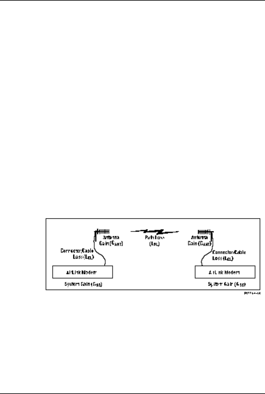
Use the following formula to calculate the fade margin (see Figure 2-3):
Fade Margin = GSG + GANT - LCL - LPL
where GSG is the total system gain (measured in dB), GANT is the total antenna
gain of both antennas (measured in dBi), LCL is the total connector/cable loss of
all cables (measured in dB), and LPL is the path loss (measured in dB). These
are described in more detail below.
The reliability of the link is related to the fade margin and is stated as
Availability (in percent) or annual outage time (in minutes).
Figure 2-3
Fade Margin Calculation

VoiceXtender Modem Installer’s Guide
System Planning
Rev. A - 8/97 2-5
System Gain
System gain is the total gain of the radio system, without any consideration of
the antennas or cables. It is the arithmetic difference between the transmitter’s
output power and the receiver’s sensitivity threshold. System gain (GSG in the
formula) is measured in dB. To calculate the system gain, subtract the receiver
sensitivity from the transmitter power:
(Transmit Power) - (Receiver Sensitivity) = (System Gain)
For example, the system gain for the VX at maximum power is 127 dB.
(+29 dBm) - (-98 dBm) = 127 dB
Antenna Gain
Antenna gain is the measure of the antenna’s ability to focus the radio
frequency (RF) energy into a preferred direction. Antenna gain (GANT in the
formula) is measured in dBi—the ratio between the power radiated by the
antenna in a specific direction over the power radiated to that direction by an
isotropic antenna fed by the same transmitter. An isotropic antenna radiates a
signal evenly in all directions.
Refer to the antenna manufacturer’s information to determine the antenna gain
for the antenna you will be using. Some antennas are specified in dBd. This
number can be converted to dBi by adding 2 dB.
Cable/Connector Loss
A directional antenna is connected to the VX modem with a coaxial cable. The
cable loss (LCL in the formula) is measured in dB, and depends on the cable
length and the type of cable you are using. You can use any 50 ohm coaxial cable
whose loss in dB per hundred feet is low enough (3 - 15 dB) so as not to contribute
significantly to the total link loss. Quality cables with less than 7 dB loss per
hundred feet are sold by Cylink and Cylink distributors.
Free Space Path Loss
Due to reflections from the ground and other objects, the actual path loss
between the transmitting and receiving antennas might differ significantly
from the calculated path loss when both antennas are placed in a “free space”
environment. Unfortunately, the additional loss due to these effects is difficult
to calculate and requires precise knowledge of the geometry of the link and
surrounding materials which, in most cases, is not available.

VoiceXtender Modem Installer’s Guide
System Planning
2-6 Rev. A - 8/97
Typically, the largest contributor to “link loss” is the loss of power as the
signal travels through space. This contribution, called Free Space Path Loss,
can be easily calculated as follows: To determine the free space path loss,
determine the distance between the VX modems for your application and refer
to Table 2-1, or use the following formula:
attenuation in dB = [96. 6 + 20 LOG (distance in miles)
+ 20 LOG (frequency in GHz)]
Table 2-1
Free Space Path Loss Between Two Isotropic Radiators
Distance
(Miles) Path Loss
@ 915 MHz
(L-Band)
1 96 dB
2 102 dB
3 105 dB
4 108 dB
5 110 dB
6 111 dB
7 113 dB
8 114 dB
9 115 dB
10 116 dB
15 120 dB
20 123 dB
25 125 dB
30 126 dB

VoiceXtender Modem Installer’s Guide
System Planning
Rev. A - 8/97 2-7
Table 2-2
Free Space Path Loss Between Two Isotropic Radiators
Distance
(kilometers) Path Loss
@ 915 MHz
(L-Band)
1 92 dB
2 98 dB
3 101 dB
4 104 dB
5 106 dB
6 107 dB
7 109 dB
8 110 dB
9 111 dB
10 112 dB
15 115 dB
20 118 dB
25 120 dB
30 121 dB
35 123 dB
40 124 dB
50 126 dB
NOTE The calculation for attenuation using kilometers is:
attenuation in dB = [92. 4 + 20 LOG (distance in kilometers) + 20 LOG (frequency in GHz)]
VoiceXtender Modem Installer’s Guide
System Planning
2-8 Rev. A - 8/97
Application Examples
VoiceXtender modems can be used in point-to-point or hub configurations. The
following subsections show typical examples of each of these applications, and
include configuration information for the modems.
For detailed information on configuration parameters and switch settings, refer
to Chapter 3, “Installation and Setup. ”
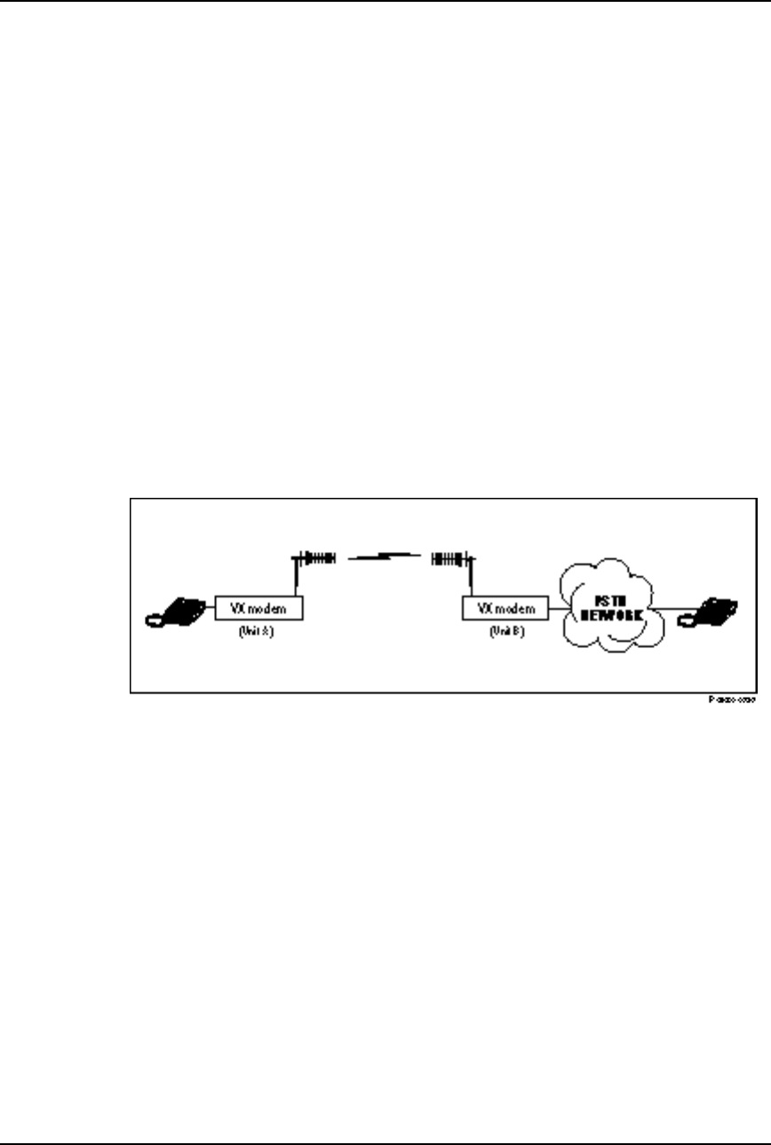
Example 1: Point-to-Point Application
In this application, a remote telephone is connected to the main Public
Switched Telecommunications Network (PSTN) network. This allows the
remote telephone to communicate with any telephone connected to the PSTN
network. As shown in Figure 2-4, the VoiceXtender provides a point-to-point
radio voice link between the remote telephone and the PSTN network.
Figure 2-4
Point-to-Point Application
You will only need to configure the parameters on each modem. The following
list describes the parameters for this particular application.
❚RF Channel: Any of the ten available channels can be used. Choose a
channel that is not being interfered with. The channel selected for master
and slave units must be the same.
(SW1-1, 1-2, 1-3, 1-4)
❚Transmit Output Power: Typically, the minimum necessary power is
recommended for most applications. Both units in a link need not be set to
the same power level.
(SW1-5, 1-6, 1-7)
VoiceXtender Modem Installer’s Guide
System Planning
Rev. A - 8/97 2-9
❚Burst Synchronization Timing: The master and slave are both configured
for internal burst synchronization.
(SW1-8 ON)
❚Phone/Line: The switch must indicate which AirLink modem is connected
to the phone and which modem is connected to the line. In this example,
Unit A would be set to Phone and Unit B would be set to Line.
(SW2-1)
❚Master/Slave: One AirLink modem must be specified as a master and one as
a slave.
(SW2-2)
❚Sleep/Normal: Set both modems to Normal.
(SW2-3 OFF)
❚Pseudo-Random Noise Sequence: Specify the same pseudo-random noise
(PN) sequence on both AirLinks. PN sequence numbers range from 1 to 8.
(SW2-6, 2-7, 2-8)
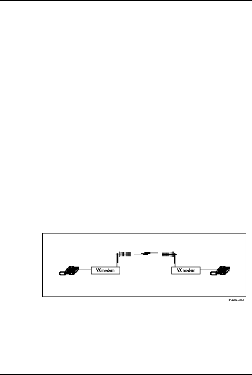
Example 2: Point-to-Point Intercom Application
In this application, two telephones are connected in an intercom configuration.
In this configuration, when either phone is taken off-hook, the other telephone
will ring. The two telephones can only communicate with each other, and are
not connected to any networks. As shown in Figure 2-5, VoiceXtender modems
are used to provide a point-to-point radio voice intercom link between the two
telephones.
Figure 2-5
Point-to-Point Intercom Application
You only need to configure the parameters on each modem. The following list
describes the parameters for this particular application.

VoiceXtender Modem Installer’s Guide
System Planning
2-10 Rev. A - 8/97
❚RF Channel: For the VoiceXtender, any of the ten available channels can
be used. Choose a channel that is not being interfered with. The channel
selected for master and slave units must be the same.
(SW1-1, 1-2, 1-3, 1-4)
❚Transmit Output Power: The minimum required power is typically
recommended for most applications. Both units in a link need not be set to
the same power level.
(SW1-5, 1-6, 1-7)
❚Burst Synchronization Timing: The master and slave are both configured
for internal burst synchronization.
(SW1-8 ON)
❚Phone/Line: The switch must be set to the Phone position on both AirLink
modems.
(SW2-1 OFF)
❚Master/Slave: One modem must be specified as a master and one as a slave.
(SW2-2)
❚Sleep/Normal: Set both modems to Normal.
(SW2-3 OFF)
❚Pseudo-Random Noise Sequence: Specify the same pseudo-random noise
(PN) sequence on both modems. PN sequence numbers range from 1 to 8.
(SW2-6, 2-7, 2-8)
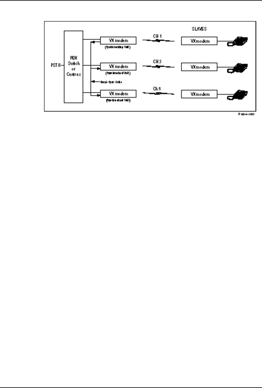
Example 3: Hub Application
In this application, several telephones are connected to the switch or centrex in
the same building. As shown in Figure 2-6, VoiceXtender modems are used in a
hub configuration. Because the telephones and switch are located in the same
building, the low-gain omnidirectional antenna provided with the unit can be
used. No path analysis is required with an omnidirectional antenna and short
distances.
VoiceXtender Modem Installer’s Guide
System Planning
Rev. A - 8/97 2-11
Figure 2-6
Hub Application
You need to configure each modem. The following list describes the parameters
for this particular application.
❚RF Channel: Each AirLink modem pair is assigned a unique channel to
avoid interference. In this example, channels 1, 3, and 5 are recommended.
(SW1-1, 1-2, 1-3, 1-4)
❚Transmit Output Power: Typically, the minimum required power is
recommended for most applications. However, the transmit power for the
slave modems must be set to minimize the adjacent channel interference at
the hub units.
(SW1-5, 1-6, 1-7)
❚Burst Synchronization Timing: In a hub configuration where there are
multiple modem pairs, it is critical that all the master modems transmit
and receive at the same time to minimize inter-channel interference.
In this case, one modem (the synchronizing unit) is configured for internal
burst timing. All other master modems (the synchronized units) are
configured for external burst timing and synchronize their transmit bursts to
the signal from the synchronizing master. The slave modems are configured
for internal burst timing and derive their burst synchronization from their
received RF signal.
(SW1-8)
❚Phone/Line: On the master modems, the Phone/Line switch must be set to
the Line position. On the slave modems, the Phone/Line switch must be set
to the Phone position.
(SW2-1)

VoiceXtender Modem Installer’s Guide
System Planning
2-12 Rev. A - 8/97
❚Master/Slave: The modems connected to the switch or centrex (all in one
location) are configured as masters, and the modems connected to the
telephones are configured as slaves.
(SW2-2)
❚Sleep/Normal: Set all modems to Normal.
(SW2-3 OFF)
❚Pseudo-Random Noise Sequence: For each modem pair, specify a unique
pseudo-random noise (PN) sequence to help separate adjacent channels. In
this example, channel 1 uses PN sequence 1, channel 3 uses PN sequence 2,
and channel 5 uses PN sequence 3.
(SW2-6, 2-7, 2-8)
NOTE VoiceXtender modems can be burst synchronized with other VoiceXtender VX64modems
and with AirLink model 64MP, 128 and 256 data modems. If VX64 modems are burst
synchronized with data modems, one of the data modems must be configured as the
synchronizing unit.

Rev. A - 8/97 3-1
C
CHAPTER
HAPTER 3
3
Installation and Setup
Installation and Setup
This chapter contains information on how to install, configure, and
cable your VoiceXtender modem. The procedures and descriptions in
this chapter assume you have read Chapter 2, “System Planning.”
Inside this chapter:
System Setup........................................................................3-2
Switch Settings....................................................................3-2
Cabling the Modem................................................................3-6
System Startup..................................................................3-10

VoiceXtender Modem Installer’s Guide
Installation and Setup
3-2 Rev. A - 8/97
System Setup
Ensure that each shipping container includes these items:
❚One AirLink VoiceXtender modem
❚One external power supply with cord
❚Omnidirectional antenna
❚RJ11 cables
❚This document.
Depending on your specific application, you may need to purchase the following
additional items from Cylink or your distributor to install the modem at your
site.
❚For hub applications, a coaxial cable (RG-58 is recommended) and BNC
“Tee” connectors to connect the modems designated as synchronizing and
synchronized units.
❚A high-gain omnidirectional or directional antenna, and coaxial cable
to connect the antenna to the modem
NOTE Save the shipping cartons and packing materials. You will need the carton and materials if
you ever need to ship the equipment elsewhere.
Check the materials against the packing list to make sure that you have
received everything. If something is missing or if you discover shipping
damage, contact your distributor.
Switch Settings
The modem is configured through two configuration switches (each with a block
of eight ON/OFF switches) located at the rear of the modem.
NOTE A label showing the configuration switch settings is attached to the bottom of the modem.
The label provides a quick reference of the switch settings. .
To set the switch to the “ON” position, push the switch up, toward the top
cover of the modem. To set the switch to the “OFF” position, push the switch
down, toward the bottom of the modem.

VoiceXtender Modem Installer’s Guide
Installation and Setup
Rev. A - 8/97 3-3
NOTE Settings not specified on this chart are reserved for future use, and should not be used.
To assist you in setting the configuration switches, use the Switch Configuration
Worksheets provided in Appendix B to record the appropriate settings for your
application.
VoiceXtender Modem Installer’s Guide
Installation and Setup
3-4 Rev. A - 8/97
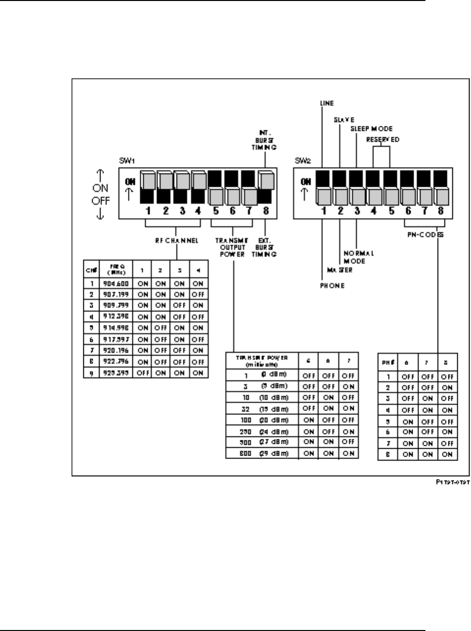
VoiceXtender Switch Settings
Figure 3-1
AirLink VoiceXtender VX64 Switch Settings
VoiceXtender Switch Parameters
RF Channel Switches (SW1-1 through SW1-4)
These switches set the center frequency of each RF channel used by the modem.
The frequency ranges from 902 to 928 MHz and is divided into ten channels. The

VoiceXtender Modem Installer’s Guide
Installation and Setup
Rev. A - 8/97 3-5
center frequency assigned to each channel has been chosen to provide the
greatest flexibility of use. The VoiceXtender VX64 modem requires a segment of
bandwidth that is only one channel wide. Therefore, all nine channels are
available for voice applications.
Each modem used in a “logical” application (e.g., the master and slave units of
a single point-to-point link) must be configured with the same channel.
Transmit Output Power Switches (SW1-5 through SW1-7)
These switches set the power level for the VX modem. The transmit level you
select depends on local regulations and your application; however, the
minimum required power normally is recommended for most applications.
Depending upon the application, the setting selected as the transmit output
power is also used to determine the system gain. For more information, refer to
Path Analysis in Chapter 2, “System Planning.”
Burst Synchronization Timing Switch (SW1-8)
This switch sets the timing used to synchronize the communication between
modems - either Internal Burst Timing or External Burst Timing.
When an modem pair operates independently (point-to-point application), the
slave and master modems are configured for internal burst timing. (Slave units
are always configured for internal burst timing.)
In a hub configuration where there is more than one modem pair, it is critical
that all the modems transmit and receive at the same time to minimize inter-
channel interference. In this case, the synchronizing modem is configured for
internal burst timing and the synchronized modems are configured for external
burst timing. The burst synchronization signal is derived from the transmit
clock source of the synchronizing modem through the sync connection.
See the hub configuration is illustrated in Chapter 2, “System Planning.”
NOTE VoiceXtender modems can be burst synchronized with other VoiceXtender modems and
with model 64MP, 128 and 256 AirLink data modems. If VoiceXtender modems are burst
synchronized with AirLink data modems, one of the data modems must be configured as
the synchronizing unit.

VoiceXtender Modem Installer’s Guide
Installation and Setup
3-6 Rev. A - 8/97
Phone/Line Switch (SW2-1)
This switch sets the modem connection to the phone or the line. When the
modem is set for Phone, it provides a standard ring current to ring the phone.
(The current is sufficient to ring at least five phones.)
Master/Slave Switch (SW2-2)
This switch sets the modem to be a master unit or slave unit. One modem in the
pair must be the master and the other modem must be the slave. The master
modem transmits continuous bursts while the slave transmits only in response to
the master as long as the slave’s RTS is activated.
Sleep/Normal Mode Switch (SW2-3)
This switch sets the modem’s communication status. When set to Normal mode,
the modems can communicate and the green SYNC light will be illuminated.
When set to Sleep mode, the green SYNC light is off and the modems cannot
communicate until the switch is returned to the Normal (OFF) position.
Pseudo-Random Noise Sequence Switches (SW2-6 through SW2-8)
These switches set the pseudo-random noise (PN) sequence (1 through 8) for the
modem. This is the bit sequence that actually spreads the spectrum.
The modem pair (the master and slave) must be configured for the same PN
sequence. Different PN sequences are used to reduce inter-channel and co-
channel interference between modem pairs. All PN codes are equally effective.
VoiceXtender Modem Installer’s Guide
Installation and Setup
Rev. A - 8/97 3-7
Cabling the Modem
How the modem is cabled depends on your application. Use the guidelines in
the following subsections to assist you in cabling the modem.
Before cabling the modem, ensure that the configuration switches (described in
the previous sub-section) are set correctly for each modem.
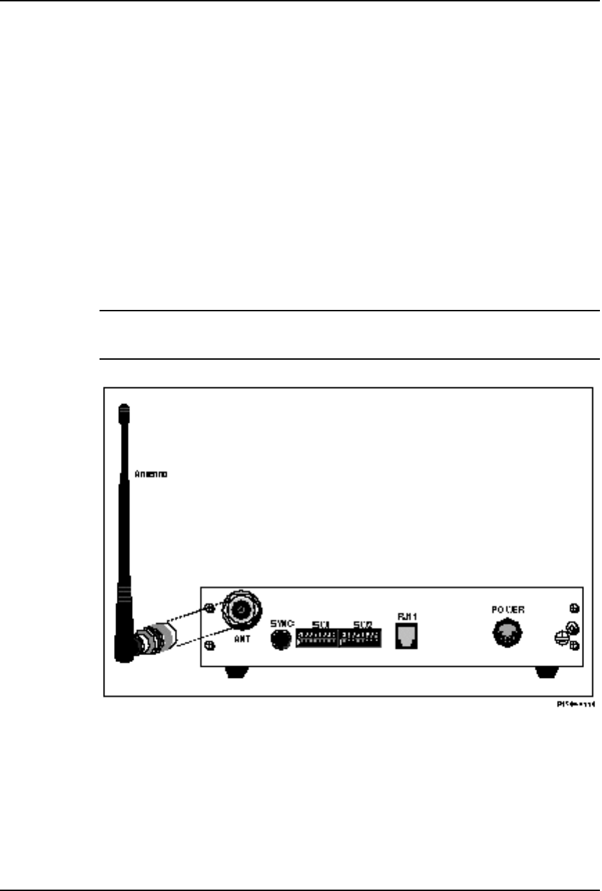
Installing the Antenna
As shown in Figure 3-2, the antenna is connected to the rear of the modem
through the antenna connector (labeled ANT).
CAUTION When testing the radios prior to installation, do not connect the antenna connector of one
radio to the antenna connector of another radio. Doing so can cause severe damage to
the receiver.
Figure 3-2
Connecting a Low-Gain Omnidirectional Antenna
When using a high-gain omnidirectional or directional antenna, a coaxial cable
is used to connect the antenna to the modem. For more information on antenna
installation, refer to “Antenna Alignment” in this chapter and the
manufacturer’s documentation that accompanies the antenna.
VoiceXtender Modem Installer’s Guide
Installation and Setup
3-8 Rev. A - 8/97
System Grounding
Direct grounding of the antenna, mast, and tower provides some protection
against lightning strikes and static buildup. A direct electrical connection
should be made to a suitable grounding rod at the base of the tower or mast using
at least #10 AWG ground wire, or its equivalent, and non-corrosive hardware.
For details and safety standards, consult the appropriate electrical code or a
similar document. Use lightning arrestors in appropriate places.
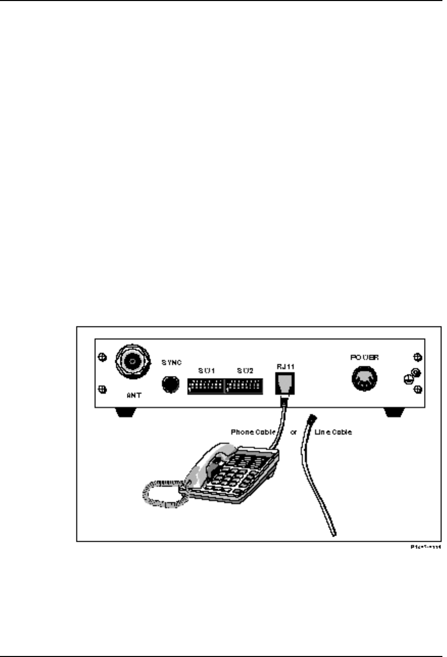
Connecting the Line/Phone Interface
The RJ11-type modular connector (labeled RJ11 on the modem) is provided to
connect your phone or the line from the network (Figure 3-3).
The slave modem typically is connected to the phone and the master modem is
connected to the line because in a hub configuration the master modems must be
centrally located for burst synchronization. It is possible, however, that
several master modems connected to a combination of phones or lines can also be
hub configured, as long as they are co-located.
The switch settings determine whether the connector is used for a phone or a
line. Ensure that the switch settings correspond to the correct cabling for the
line and phone.
Figure 3-3
Connecting the Line and Phone Interface
VoiceXtender Modem Installer’s Guide
Installation and Setup
Rev. A - 8/97 3-9
For an intercom application (private line), connect only the phones to the
master and slave modems. When you pick up one phone, the modem
automatically rings the other phone (you will hear a clicking sound on your
phone that indicates that the other end is ringing).
Signal assignments for the RJ11 can be found in Appendix A, ”Specifications.”
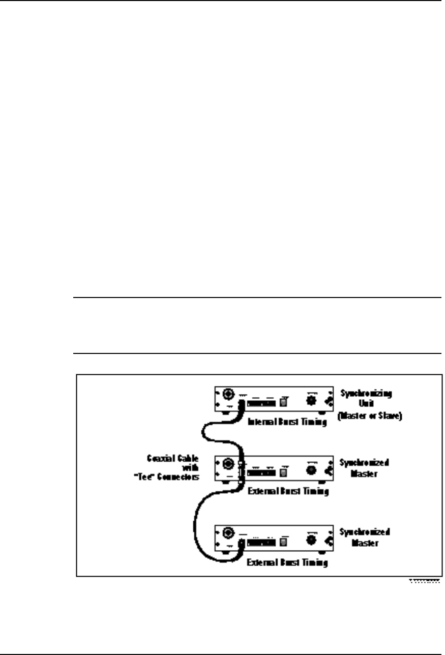
Cabling a Hub Application
If you have a hub application where more than one pair of AirLink modems is
required, you must cable the co-located modems together with a coaxial cable so
that all the modems transmit and receive synchronously.
Cable the Burst Sync connector (labeled SYNC on the modem) of the
synchronizing modem to the Burst Sync port of the synchronized master modem
(see Figure 3-4). When connecting more than one synchronized master modem,
attach BNC “Tee” adapters to the Burst Sync connector of all but the last of the
downstream master modems. For most applications, up to 20 meters total of
cable can be used between AirLink modems and up to 16 master modems can be
connected.
NOTE Ensure that all cable connections are secure.
VoiceXtender modems can be burst synchronized with other VoiceXtender modems and
with model 64MP, 128 and 256 AirLink data modems. If VoiceXtender modems are burst
synchronized with AirLink data modems, one of the data modems must be configured as
the synchronizing unit.
Figure 3-4
Burst Synchronization Cabling
VoiceXtender Modem Installer’s Guide
Installation and Setup
3-10 Rev. A - 8/97
NOTE Burst synchronizing cable and tee connectors are available from Cylink and Cylink
distributors. RG-58 coaxial cable is recommended.
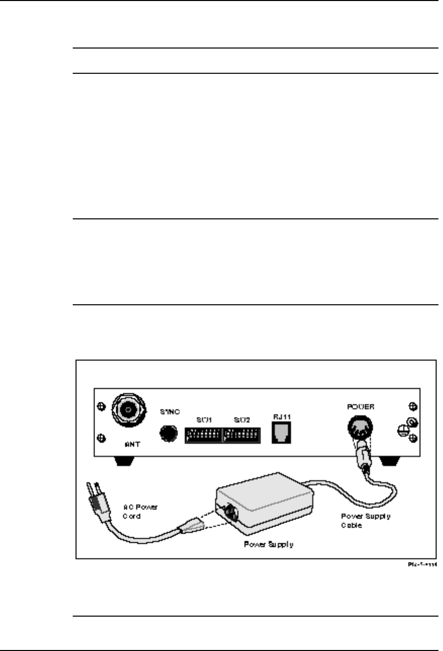
Connecting the Power
The VX uses an external power supply that is provided with the modem (Figure
3-5). To apply power to the modem, plug the five-pin DIN connector of the
power supply cable into the modem (labeled POWER). Next, plug the AC
power cord into the power supply, then into the grounded electrical outlet.
Connect the ground stud on the back of the modem to the radio system ground.
WARNING To avoid the danger of electrical shock or power loss, ensure that the power cord is
securely seated in the receptacle on the modem. This equipment is designed to work with
electrically grounded systems. The product’s AC power cord ends in a three-pole
grounding plug. Do not use a three-pole to two-pole adapter with the plug.
Verify that the outlet you intend to use is properly installed and grounded; the outlet used
must comply with the local electrical code for the country it is installed in. To ensure your
safety, only connect the power cable to a properly grounded outlet.
Pin assignments for the DIN connector can be found in Appendix A,
“Specifications.”
Figure 3-5
Connecting the Power

VoiceXtender Modem Installer’s Guide
Installation and Setup
Rev. A - 8/97 3-11
NOTE DC power supplies are available from Cylink or Cylink distributors.
System Startup
After configuring and cabling the modems (master and slave), the green
POWER indicator on the front of the modem will be illuminated. If the
POWER indicator is not on, ensure that the connection is secure.
If the modems are communicating, the SYNC indicator on the front of each
modem will be illuminated. If the SYNC indicator is not illuminated, it is
possible that the fade margin was not accurately determined or the antennas
are not properly aligned. See the following section about properly aligning the
antennas.
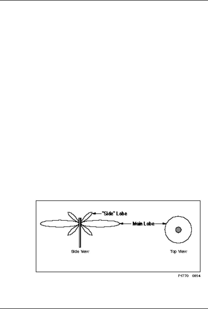
Directional Antenna Alignment
To ensure that the modems are operating optimally when directional antennas
are used, it is important that the antennas are aligned properly. Coarsely align
the antenna to ensure that you are on the peak of the main lobe, then fine tune
the alignment. In addition to physically adjusting the direction of the antenna,
you might need to adjust the transmit power level, using the configuration
switches on the unit.
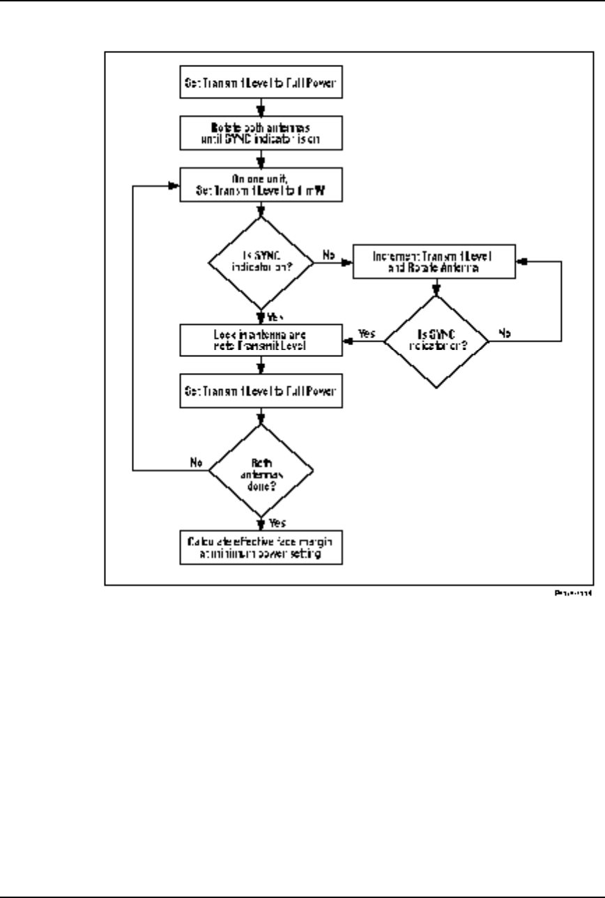
To align the antenna, use the following two procedures and refer to the flow
chart shown in Figure 3-6.
Procedures to Coarsely Align the Antenna
The first step in the antenna alignment process is to coarsely align the antenna
on each unit using the following steps:
1. With the configuration switch located on the rear of the modem, set the
Transmit Level to full power on both modems.
See the Switch Configuration section in this chapter for more details.
2. Move each antenna until the SYNC indicator on the modem is illuminated.
When the SYNC indicator is illuminated, it indicates that the link is
established; however, the antenna can be aligned on a side lobe rather than
the main lobe.

VoiceXtender Modem Installer’s Guide
Installation and Setup
3-12 Rev. A - 8/97
Procedures for Fine Tuning the Antenna Alignment
The second step in the antenna alignment process is to fine tune the antenna to
ensure that the link is operating at the center of the main lobe. To fine tune the
antenna alignment, systematically adjust the transmit power by using the
following steps:
1. Set the master modem Transmit Level to 1 milliwatt.
The link will go down, and the SYNC indicator will go out. The slave
modem should still be at full power.
2. Increment the Transmit Level on the master modem, then slowly rotate the
antenna to attempt to illuminate the SYNC indicator on the slave.
Continue to cycle through the Transmit Levels and rotate the antenna at
each cycle until the SYNC indicator is illuminated.
When the SYNC indicator is illuminated, it indicates that the antenna is
correctly aligned on the main lobe.
3. Once the SYNC indicator is illuminated, note the Transmit Level, and
repeat steps 1 and 2 on the other modem.
4. Once both antennas have been finely tuned, the effective fade margin can be
calculated using the ratio of full power to the minimum power necessary to
illuminate the SYNC indicator.
VoiceXtender Modem Installer’s Guide
Installation and Setup
Rev. A - 8/97 3-13
Figure 3-6
Antenna Alignment Flow Chart
VoiceXtender Modem Installer’s Guide
Installation and Setup
3-14 Rev. A - 8/97
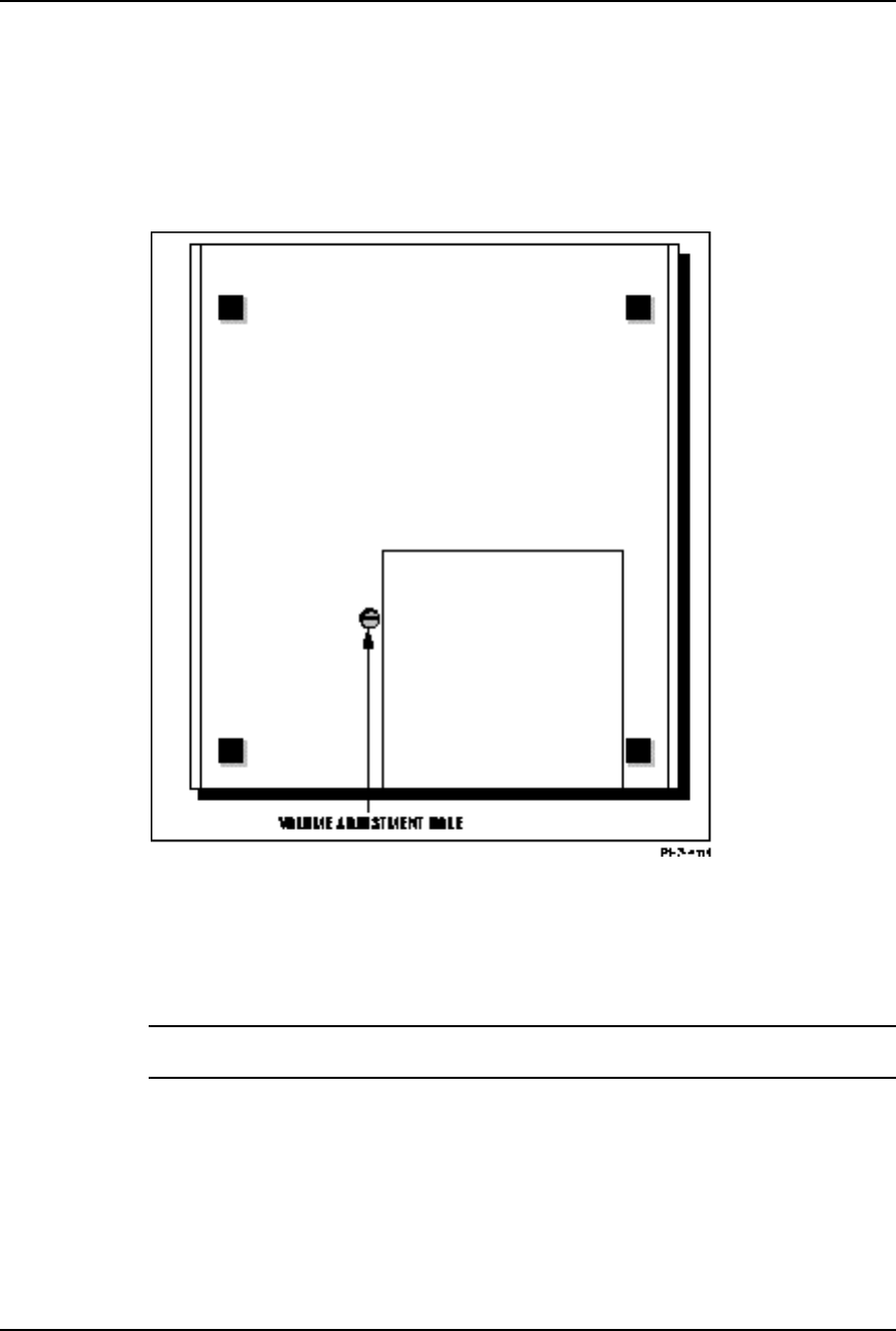
Adjusting the Audio Receive Level
The audio and listening volume of a telephone (or line) connected to the
VoiceXtender modem can be adjusted using the Audio Receive Level control on
the bottom of the AirLink modem (see Figure 3-7).
Figure 3-7
Volume Adjustment
Using a small blade-type screwdriver, turn the control clockwise to increase the
level, or counter-clockwise to decrease it.
NOTE This adjustment is completely independent of the RF system and does not affect the
transmit power level.

Rev. A - 8/97 4-1
C
CHAPTER
HAPTER 4
4
Troubleshooting
Troubleshooting
This chapter contains information on solving possible operational
problems when using VoiceXtender modems.
Inside this chapter:
Operational Problems..........................................................4-2
Maintenance............................................................................4-3

VoiceXtender Modem Installer’s Guide
Troubleshooting
4-2 Rev. A - 8/97
Operational Problems
Following are some possible operational problems you might encounter when
using the modem. If you encounter any of these problems, we recommend going
through the following check list to resolve the problem before contacting
Cylink Customer Support.
The primary tool used to troubleshoot the modem is the SYNC indicator on the
front panel of the modem.
SYNC INDICATOR is OFF, and was never ON before
❚Is the POWER light ON? Verify correct input power.
❚Are both modems set to the same channel?
❚Are both units set to the same PN code?
❚Is the burst timing switch in the correct position?
❚Is the master/slave switch in the correct position?
❚Check cable connections.
❚Check antenna connection and alignment.
SYNC INDICATOR is OFF, but was ON before
❚Is the POWER light ON? Verify correct input power.
❚Check switch settings. Have they been changed?
❚Check the cable connections.
❚Check antenna connection and alignment.
SYNC INDICATOR is ON, but there is no voice transmission
❚Check phone and line connections.
❚Check that audio level control is not turned completely down.
AUDIO VOLUME is too low.
❚Adjust audio receive level on the bottom of the modem.

VoiceXtender Modem Installer’s Guide
Troubleshooting
Rev. A - 8/97 4-3
Maintenance
When cleaning the unit, use a soft, moist, lint-free cloth. DO NOT USE
abrasive or chemical cleaners. Cylink will perform any other necessary
maintenance, including component replacements and internal adjustments.

Rev. A - 8/97 A-1
A
APPENDIX
PPENDIX A
A
Specifications
Specifications
This appendix contains the specifications for VoiceXtender modems.
Inside this appendix:
General Specifications........................................................A-2
Interface Specifications.....................................................A-7

VoiceXtender Modem Installer’s Guide
Specifications
A-2 Rev. A - 8/97
General Specifications
Table A-1
General Specifications
General
Operates as a cordless phone or as an intercom.
2-wire loop start signaling
Cordless phone: FXO (Interfacing phone), FXS (Interfacing line)
(see Tables A-2 and A-3.)
Intercom: Both units set FXO (Interfacing phone)
(see Table A-2.)
Operates with standard DTMF (EIA-470) phones
600 Ohm termination impedance, tolerance ± 5%
End to End SINAD of 30-36 dB over the voice band (200-3400 Hz)
End to End Audio Loss/Gain: Adjustable to maximum of + 3 dB
Audio muting during link fades
DTMF Address Signaling (Dial Pulse optional)
Meets FCC Part 68 Compliance
Table A-2
FXO Specifications
FXO (Interfacing Phone) Signaling
Battery feed circuitry maintains loop current of 16 mA into maximum of 1.0 kilohm Loop
resistance (this includes phone load). Maximum Feed Current 100 mA
Rings maximum of 5 REN-B Loads.
Ring signal is a filtered squarewave with nominal voltage 86Vp and nominal frequency 20
Hz.
Ring cadence of 2 sec ON and 4 sec OFF
Ring tripping in less than 200 msec

VoiceXtender Modem Installer’s Guide
Specifications
Rev. A - 8/97 A-3
Table A-3
FXS Specifications
FXS (Interfacing Line) Signaling
Maximum Holding current of 100 mA without audio distortion
Detects ring signals of 40 - 110 Vrms @ 17-34 Hz
Ringer equivalence (REN): 0.3A (U.S.)
Load Number: 7 (Canada)
Table A-4
Physical and Environmental Specifications
Parameter Specification
Dimensions Height 2.125 inches (55 mm)
Width 8.5 inches (215 mm)
Depth 10.5 inches (265 mm)
Weight 4 pounds (2 kg)
Construction Aluminum outer housing and inner chassis
User Interface Front Panel indicators
POWER: Power On/Off
SYNC: Radio Link OK/Down
Rear Panel
External Switches for configuration
Operating Temperature -34° to 74° C
Storage Temperature -40° to 80° C
Relative Humidity Up to 95% non condensing
Shock and Vibration NSTA Project 2A compliant
Table A-5
Connector Specifications
Parameter Specification
Antenna Connector N-Type (female)
Burst Synchronization Connector BNC (female), used for Hub Synchronization
Phone/Line Connector RJ11-type, 6-position modular jack
Power Connector 5-pin DIN Connector (female)

VoiceXtender Modem Installer’s Guide
Specifications
A-4 Rev. A - 8/97
Table A-6
Power Specifications
Parameter Specification
External AC Power Supply:
Input
Power Cable
Output
Dimensions
Weight
100-250 VAC @ 50/60 Hz, 0.3-0.7A
According to model ordered
+5, ± 12 VDC, cable terminated with 5-pin male DIN
Connector
Height 2.00 inches (50.8 mm)
Width 3.40 inches (86.4 mm)
Length 5.87 inches (149.1 mm)
1.3 pounds (.6 kg)
Maximum Power Consumption:
(power supply plus AirLink) AC Power Supply - 23 Watts
DC Power Supply - 21 Watts
Table A-7
User Interface Configuration Switches
(See Chapter 3, “Installation and Setup” for details.)
Switch Setting
SW1-1 through SW1-4 Radio Frequency Channel
SW1-5 through SW1-7 Transmit Output Power
SW1-8 Internal Burst Timing or External Burst Timing
SW2-1 Phone or Line
SW2-2 Master Unit or Slave Unit
SW2-3 Sleep Mode or Normal Mode
SW2-4 and SW2-5 Not Used
SW2-6 through SW2-8 PN Sequence

VoiceXtender Modem Installer’s Guide
Specifications
Rev. A - 8/97 A-5
Table A-8
General Radio Frequency Specifications
Parameter Specification
Frequency Range 902 - 928 MHz
Radio Technology Spread Spectrum using Direct Sequence
PN Sequence Length 32 bits
Modulation Technique Bi-Phase Shift Keying (BPSK), Non-Coherent
Receiver
Channel Bandwidth 5.1 MHz
Transmission Delay 5.1 msec
Sync Word Length 16 bits
Processing Gain 12 dB
System Gain
(not including antenna gain) 127 dB
Transmission Distance Up to ~10 miles with 2 Yagi directional antennas and
a direct line-of-sight.
Table A-9
Transmitter Specifications
Parameter Specification
Number of RF Channels (switch
selectable) 10 ( all non-overlapping)
Frequency Source Synthesized
Bandwidth 2.6 MHz
Carrier Frequency Stability ± 10 ppm
Output Power (switch selectable)
Tolerance
29 dBm (800 mW) maximum with
29 dB of dynamic range
± 1dB over all RF channels
± 1 dB from 0 to 50° C

VoiceXtender Modem Installer’s Guide
Specifications
A-6 Rev. A - 8/97
Table A-10
RF Channel Frequencies - AirLink VoiceXtender VX64
Channel Number Frequency (MHz)
1904.600
2 907.199
3 909.799
4 912.398
5 914.998
6 917.597
7 920.196
8 922.796
9 925.395
Table A-11
Receiver Specifications
Parameter Specification
Acquisition Time during preamble bits
Noise Figure 5 dB maximum
Receive Sensitivity -98 dBm (@ SINAD 30-36 dB over 200-3400 Hz)
Receive Overload Threshold > -10 dBm
C/I (Carrier Over Interference)
Tolerance 0 dB*
*This number is an average value for 9 uniformly spaced discrete frequencies in
the band defined by: fc - fchip to fc + fchip where fchip is 2.56 Mbps.
CAUTION When testing the radios prior to installation, do not connect the antenna connector of one
radio to the antenna connector of another radio. Doing so can cause severe damage to
the receiver.
VoiceXtender Modem Installer’s Guide
Specifications
Rev. A - 8/97 A-7
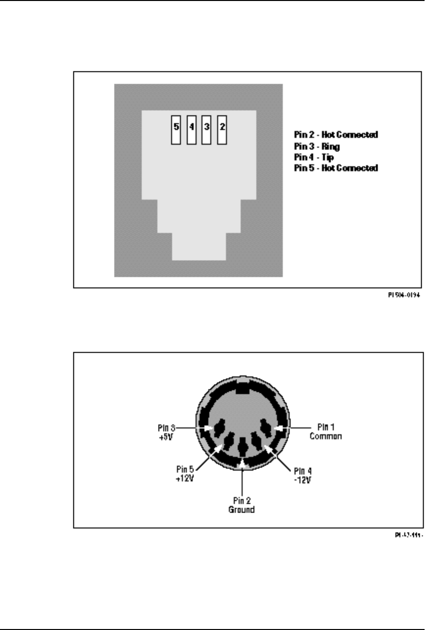
Interface Specifications
Figure A-1
Rear Panel RJ11-Type Modular Jack
Figure A-2
Rear Panel Power Input Connector (Female DIN)

Rev. A- 8/97 B-1
A
APPENDIX
PPENDIX B
B
Worksheet
Worksheet
This appendix contains a Configuration Worksheet to use to record the
configuration settings for your modems. Before installing and
configuring the modem, read Chapter 2, “System Planning.”
Inside this Appendix:
Configuration Worksheet...................................................B-2

VoiceXtender Modem Installer’s Guide
Worksheets
B-2 Rev. A- 8/97
VX Switch Configuration Worksheet
ID/Name: Serial Number:
Location: Antenna Type:
SWITCH PARAMETERS VALUES SETTING
SW1-1 through SW1-4 RF Channel (MHz) 1 2 3 4
1(904.600) ON ON ON ON
2 (907.199) ON ON ON OFF
3 (909.799) ON ON OFF ON
4 (913.398) ON ON OFF OFF
5 (914.998) ON OFF ON ON
6 (917.597) ON OFF ON OFF
7 (920.196) ON OFF OFF ON
8 (922.796) ON OFF OFF OFF
9 (925.395) OFF ON ON ON
SW1-5 through SW1-7 Transmit Power (milliwatts) 5 6 7
1(0 dBm) OFF OFF OFF
3 (5 dBm) OFF OFF ON
10(10 dBm) OFF ON OFF
32(15 dBm) OFF ON ON
100(20 dBm) ON OFF OFF
250(24 dBm) ON OFF ON
500(27 dBm ON ON OFF
800(29 dBm) ON ON ON
SW1-8 Burst
Synchronization
Timing
8
Internal Burst Timing ON
External Burst Timing OFF
SW2-1 Line/Phone 1
Line ON
Phone OFF
SW2-2 Master/Slave Unit 2
Slave Unit ON
Master Unit OFF
SW2-3 Normal/Sleep
Mode 3
Sleep ON
Normal OFF
SW2-4 and
SW2-5 Reserved N/A N/A
SW2-6 and
SW2-8 PN Sequence 6 7 8
1OFF OFF OFF
2 OFF OFF ON
3 OFF ON OFF
4 OFF ON ON
5 ON OFF OFF
6 ON OFF ON
7 ON ON OFF
8 ON ON ON

Rev. A - 8/97 C-1
A
APPENDIX
PPENDIX C
C
Glossary
Glossary
This appendix contains an alphabetical list and description of technical
terms used in this document.

AirLink VoiceXtender VX64 Modem Installer’s Guide
Glossary
C-2 Rev. A - 8/97
Antenna A transmitting or receiving device for radiated waves. The
antenna acts as a form of matching transformer for waves along a
line and waves in space so that the maximum transfer of energy
can be achieved.
Antenna Gain Antenna gain is a measure of the efficiency of an antenna
compared with the efficiency of a standard reference antenna.
The efficiency is measured in terms of the power radiated or
received in a given direction as compared with the standard
under the same conditions.
Asynchronous Data
Transmission The transmission of data in which each character is a self-
contained unit with its own start and stop bits and intervals
between characters may be uneven.
Bit Error Rate (BER) The measure of the frequency of errors in a digital transmission.
Burst Timing A form of timing in which the receiving device is synchronized to
the transmitting device by receiving bursts of data.
Cable Loss The amount of signal attenuation (loss) for a particular type of
cable of a given length.
Channel A specified frequency slot within the specified frequency band
used for transmission.
DCE Data Circuit Equipment—a communications device that
establishes, maintains, and terminates a session on a network.
DTE Data Terminating Equipment—a communications device that is
the source or destination of signals on a network.
Fade Margin The measure of how much signal attenuation the system can
endure without dropping below the minimum desired BER level.
Free Space Path Loss The loss of power of a radiated signal as it travels through space.
Full Duplex Transmission in two directions simultaneously.
Half Duplex A circuit designed for data transmission in both directions, but not
at the same time.
Handshake Signal The series of signals between a computer and another peripheral
device (for example, a modem) that establishes the parameters
required for passing data.

AirLink VoiceXtender VX64 Modem Installer’s Guide
Glossary
Rev. A - 8/97 C-3
Hub Configuration A system configuration in which several master AirLinks and
terminals are co-located. Usually, one acts as the synchronizing
modem to the others at the site.
Indicator A device that emits a visible light on the front of the AirLink
modem.
Line-of-Sight An unobstructed view from the transmit antenna to the receive
antenna.
Master Modem The master modem is the modem which controls the slave
modem. The master modem always transmits the initial burst to
which the slave modem must respond. The master modem is the
only modem capable of initiating any activity on its own.
Modem An acronym for MOdulator - DEModulator. A device used to
convert digital signals into a form suitable for long distance
transmission, and to reconvert received signals.
Omnidirectional Antenna An antenna with a radiation pattern that is the same in all
horizontal directions.
Over Sampling The process of sampling a signal at a higher than the minimum
acceptable rate to ensure greater accuracy.
Overlapping Channels A situation in which the operating channel frequency bandwidth
of one transmitting device shares part of the frequency
bandwidth of another transmitting device.
Path Loss The total amount of radio signal attenuation (loss) between the
transmitting antenna and the receiving antenna; the sum of
attenuation caused by obstacles located in the path and the free
space path loss.
Point-to-Point
Configuration A system configuration in which only one master modem
communicates with its one slave modem between the two sites.
Point-to-Multipoint
Configuration A system configuration in which one master modem communicates
with one or more slave modem.
Pseudo-Random Noise
Sequence An operation in which a random stream of data bits is generated
within limited parameters. The stream (sequence) is typically
used for encoding data for communication.
Receiver Sensitivity The measure of the ability of a receiver to differentiate between
the selected signal and background noise for a specific
performance.

AirLink VoiceXtender VX64 Modem Installer’s Guide
Glossary
C-4 Rev. A - 8/97
REN Ringer Equivalent Number. Older model phones typically have
a REN=1. Some electronic phones and other devices have a lower
REN.
RF Radio Frequency. Electromagnetic waves propagated without
guide (wire or cable) in free space.
Send Timing A timing mode where the transmit timing is provided internally
by the modem.
Simplex Operating a channel in one direction only with no ability to
operate in the other direction.
Slave Modem The slave modem is the modem which is under control of the
master modem. The slave modem always transmits a burst in
reaction to a received burst from the master modem. The slave
modem is incapable of initiating any activity of its own.
Synchronous Data
Transmission The transmission of data in which both stations are
synchronized. Timing codes are sent from the transmitting station
to the receiving station to establish the synchronization. The
data is then transmitted in continuous streams.
System Gain The overall signal gain from input to output of a device or several
devices connected as a system.
Terminal Timing A timing mode where the transmit timing is provided to the
modem via an externally wired path. Generally, this path is a
loop through the DTE.
Transmitter Output Power The amount of transmitted signal strength measured at the
antenna post of the modem.

Rev. A - 8/97 Index-1
Index
Index

VoiceXtender Modem Installer’s Guide
Index
Index-2 Rev. A - 8/97
A
additional signal attenuation 2-4
anomalous propagation conditions 2-4
antenna alignment 3-6, 3-10-11
antenna C-2
antenna gain 2-5, C-2
antenna installation 3-6
antenna options 2-1, 2-2
antenna type 2-2
application examples 2-8
asynchronous data transmission C-2
audio volume 4-2
B
bandwidth 3-4
BER (Bit Error Rate) level 2-4, C-2
BNC “Tee” adapters 3-8
BNC “Tee” connectors1-5, 3-2
Burst Sync connector 3-8
burst synchronization 2-12, 3-7
burst synchronization signal (SYNC) 1-5
burst synchronization timing, 2-9, 2-11, 3-4,
C-2 C
cable loss 2-4, C-2
Caller Number Delivery Signaling 1-3
centrex 1-3, 2-11
channel C-2
coaxial cable 2-5
communication status 3-5
configuration switches 1-5, A-4, 3-2, 3-3,
3-10
Connecting the Line/Phone Interface 3-7
Connecting the Power 3-9
connector loss 2-4
connector specifications A-3
Cylink Customer Support xiii
D
DC Power Supply A-4
DCE C-2
dimensions A-3
DIN connector 3-9, A-7
directional antennas 1-3, 3-2
distances 2-2
DTE C-2
E
effectiveness 2-2
environmental context 2-3
environmental specifications A-3
external power supply 3-9
external burst timing 2-12, 3-4
F
fade margin 2-4, C-2
fade margin calculation 2-4
features 1-1, 1-3
female DIN connector 1-5
foreign exchange office 1-3
foreign exchange station 1-3
Free Space Path Loss-Metric, 2-7
Free Space Path Loss-Mileage, 2-6, C-2
front panel description 1-4
full duplex C-2
FXO 1-3, A-2
FXS 1-3, A-2, A-3
G
general planning requirements 2-1
general specifications A-2
Glossary C-1
H
half duplex C-2
handshake signal C-2
high-gain omnidirectional or directional
antenna 3-6
hub application 2-10, 3-8
hub configuration 1-3, 1-5, 2-8, 2-11, 3-7, C-2
I
indicator C-3
installation 2-1, 2-2, 3-1
Installer’s Guide 3-2

VoiceXtender Modem Installer’s Guide
Index
Rev. A - 8/97 Index-3
Installing the Antenna 3-6
intercom application 2-10, 3-7
intercom configuration 2-10
interface specifications A-7
Internal Burst Timing 3-4
internal burst synchronization 2-9
Introduction to the VoiceXtender 1-1
isotropic antenna 2-5
L
line-of-sight 2-2, C-3
loop-start signaling 1-3
M
main lobe 3-10, 3-11
maintenance 4-3
master modem C-3
master/slave 2-9, 2-10, 2-12, 3-5
modem C-3
modem cabling 3-6
multipath fading 2-4
N
Normal mode 3-5
O
off-hook 2-10
omnidirectional antenna 2-2, 2-11, 3-2, C-3
on-premises switch 1-3
operating frequency 1-3
operational problems 4-2
output power 1-3
over sampling C-3
overlapping channels C-3
overview 1-1
P
parameters 2-10, 2-11
path analysis 2-1
path loss 2-4, C-3
phone/line 2-9, 2-10, 2-12, 3-5
physical specifications A-3
pin assignments 3-9
PN sequence 2-11, 2-12, 3-5
point-to-point applications 1-3, 2-8, 3-4
point-to-point configuration 2-8, C-3
point-to-point radio voice intercom link
2-10
point-to-point radio voice link 2-8
POWER Indicator 1-4, 3-10
power specifications A-4
power supply 3-2, 3-9
product overview 1-2
pseudo-random noise sequence 2-9, 2-11,
2-12, 3-5, C-3
Public Switched Telecommunications
Network (PSTN) network 2-8
R
Radio Frequency specifications A-5
radio synchronization 1-3
rear panel description 1-5
receiver sensitivity C-3
receiver specifications A-6
remote telephone 2-8
REN C-3
repeater application 1-5
RF C-4
RF Channel 2-8, 2-10, 2-11, 3-4
RF Channel Frequencies A-6
RJ11 cables 3-2
RJ11-type modular jack 1-5, A-7, 3-7
S
sample applications 2-1
send timing C-4
shipping container 3-2
side lobe 3-10
Signal assignments 3-7
simplex C-4
slave modem C-4
Sleep mode 3-5
sleep/normal 2-9, 2-11, 2-12, 3-5
specifications A-1
spread spectrum technology 1-2
standard ring current 3-5
standard telephone 1-3
Switch Configuration Worksheets 3-3

VoiceXtender Modem Installer’s Guide
Index
Index-4 Rev. A - 1/96
Switch Parameters 3-4
Switch Settings 3-2, 3-3
SYNC indicator 1-4, 3-10, 3-11, 4-2
SYNC light 3-5
synchronized modems 3-4
synchronizing master 2-12
synchronizing modem 3-4
synchronous data transmission C-4
System Setup 3-2
System Startup 3-10
system gain 2-5, C-4
System Grounding 3-7
system planning 2-1
T
temperature A-3
terminal timing C-4
otal antenna gain of both antennas
(measured in dBi), 2-4
total connector/cable loss of all cables
(measured in dB),2- 4
transmit output power 2-8, 2-10, 2-11, 3-4,
3-10, C-4
transmitter specifications A-5
type of antenna 2-2
V
VX modem 3-2
voice connectivity 1-2
voice modem-CODEX connection 1-3
W
weight A-3
wireless solution 1-2
worksheet B-2
Y
your distributor 3-2