WaveNet WL7412-450 Transceiver Module User Manual 5000 Product Guide R2 22
WaveNet International Inc Transceiver Module 5000 Product Guide R2 22
WaveNet >
Contents
- 1. E F Johnson Company High Specification Data Transceiver
- 2. WaveNet 5000 Mobile Terminal Product Guide
WaveNet 5000 Mobile Terminal Product Guide

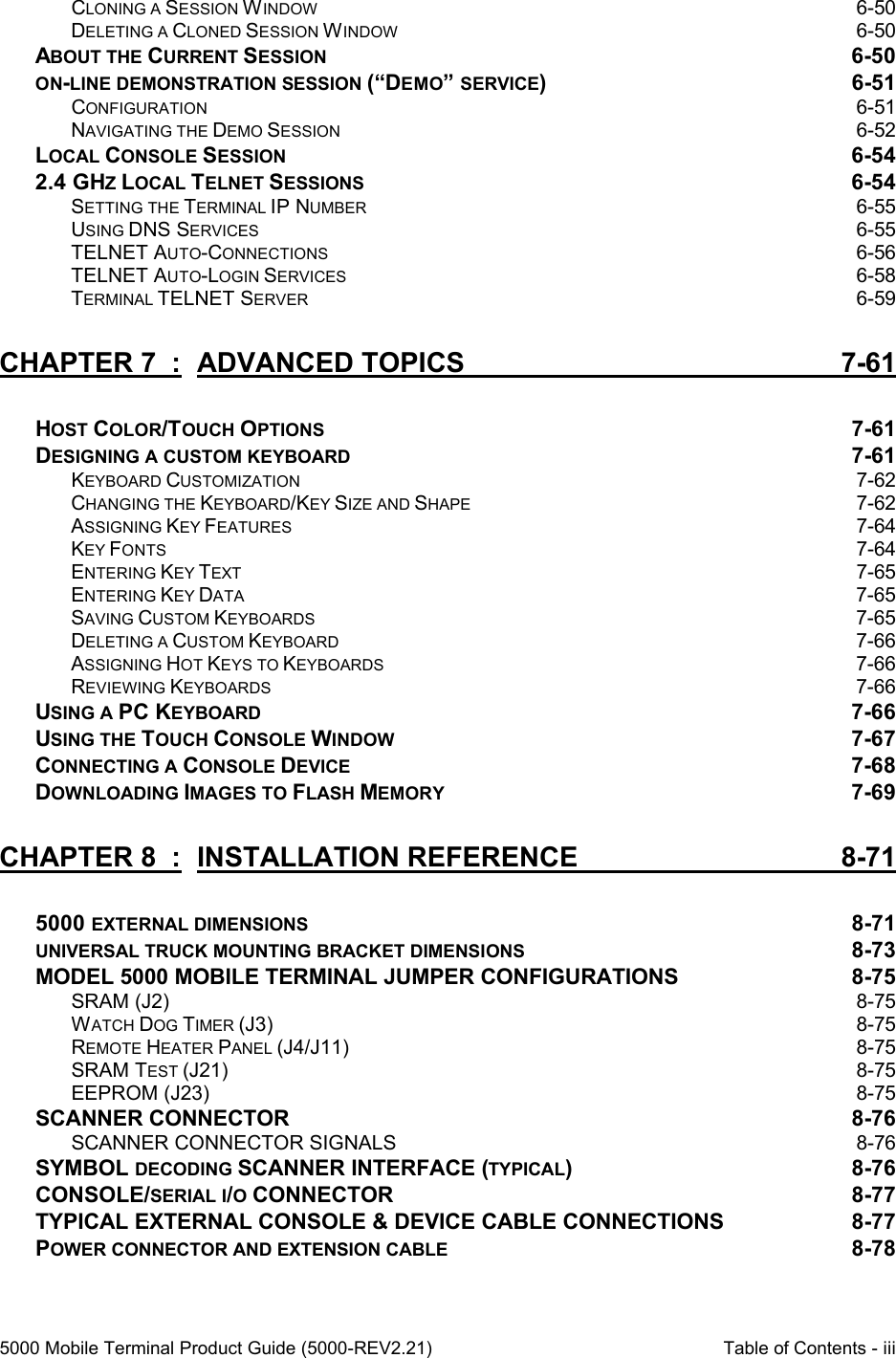


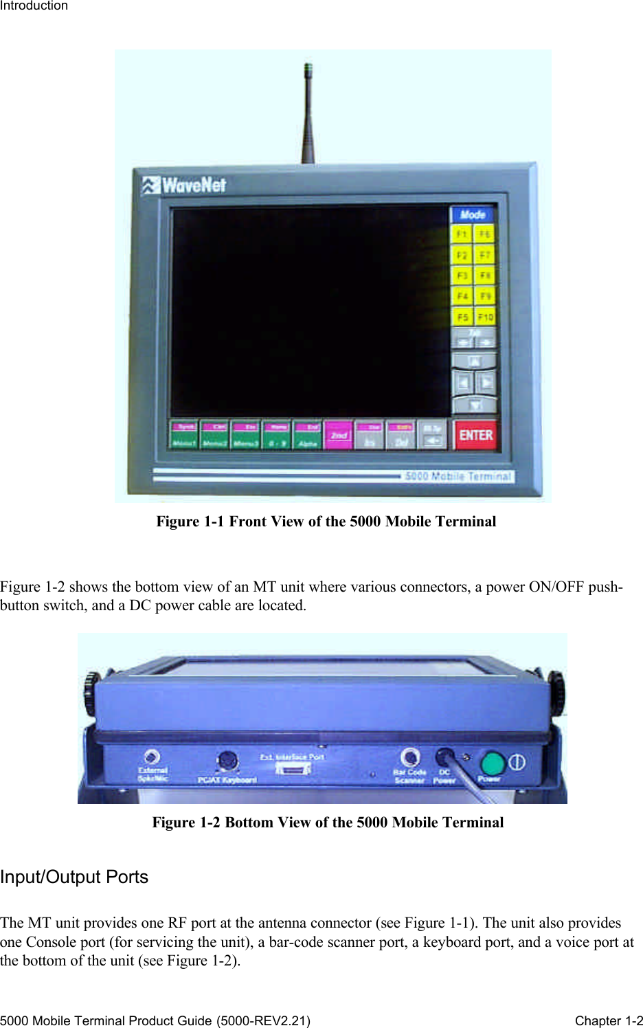
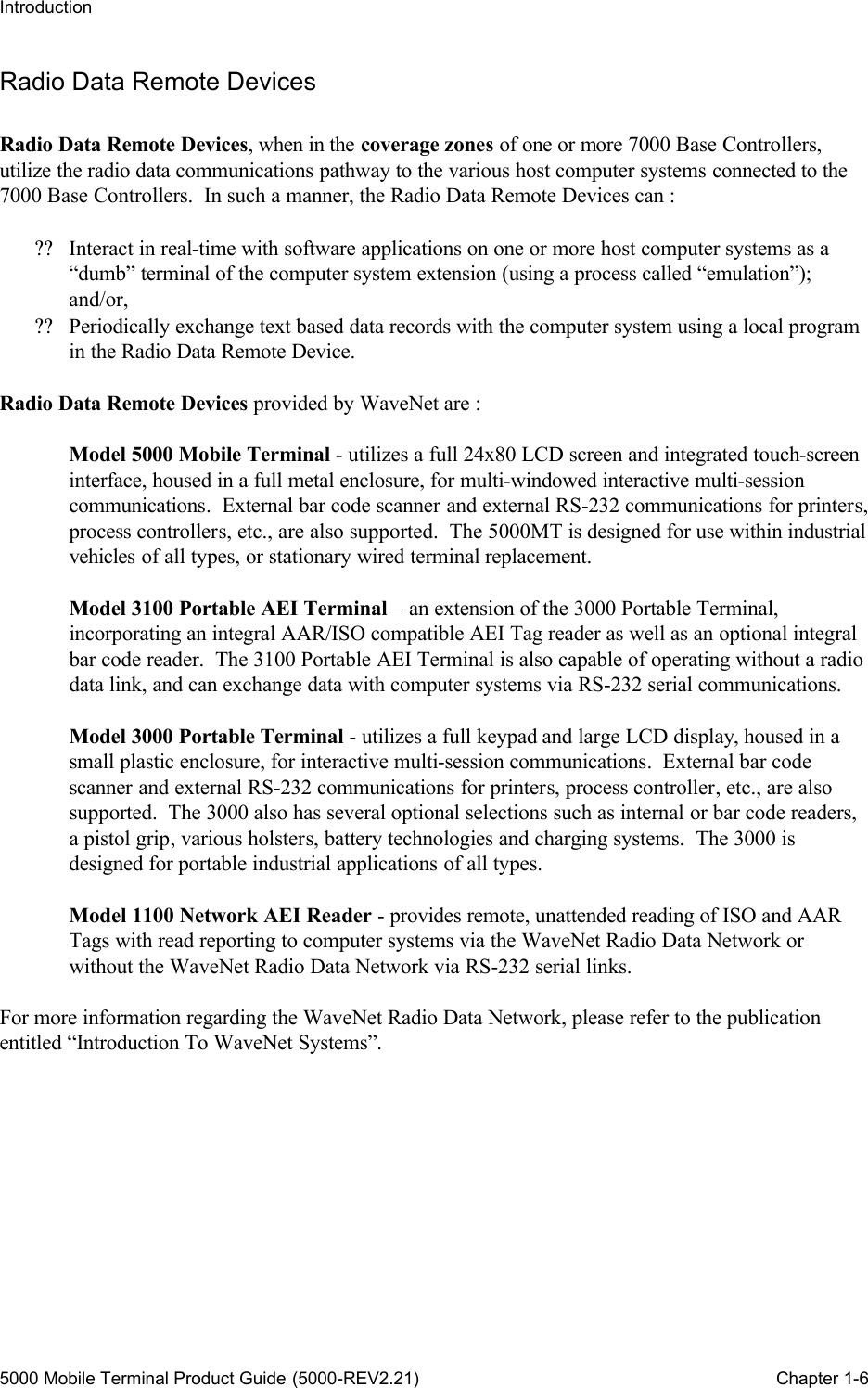
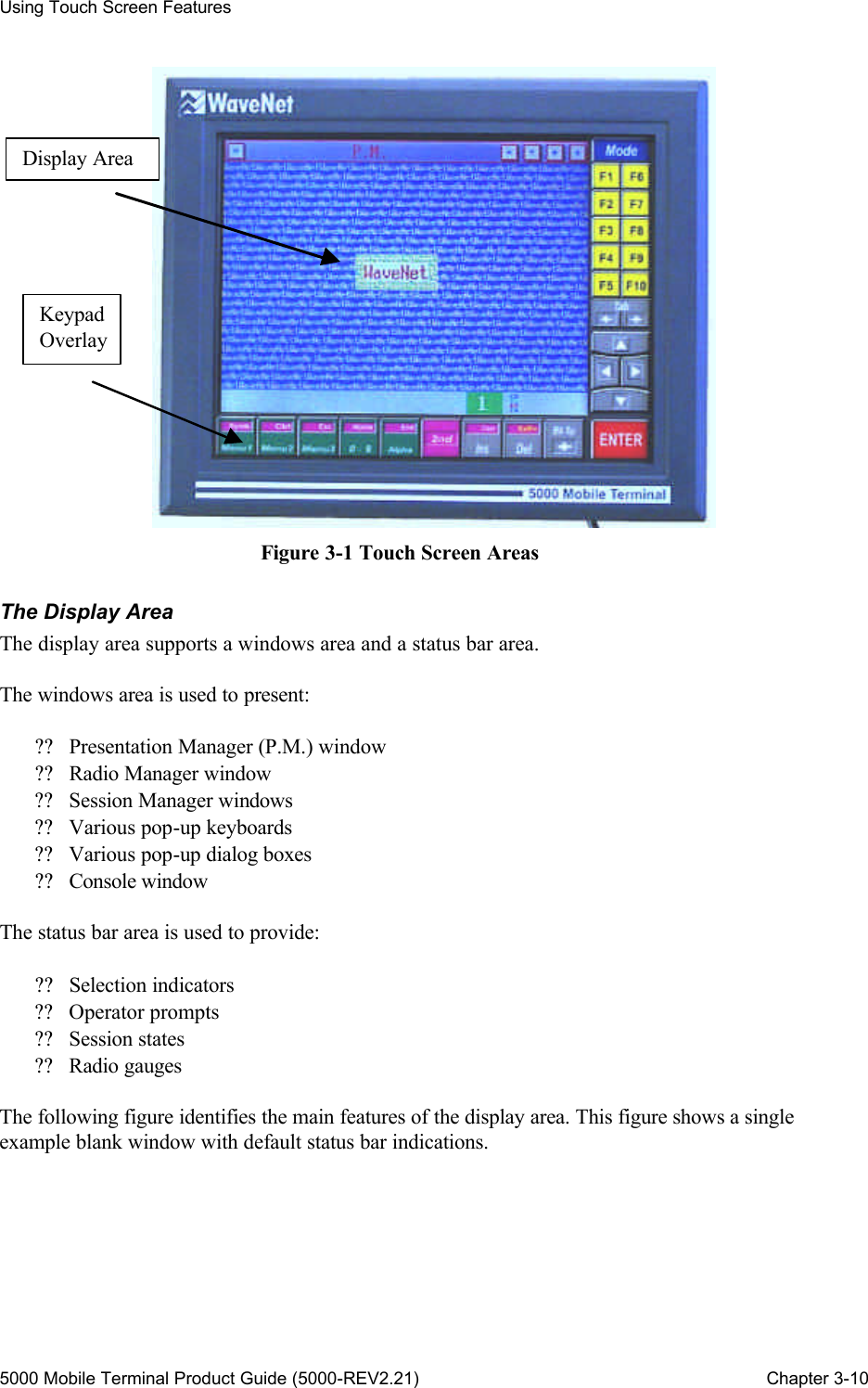
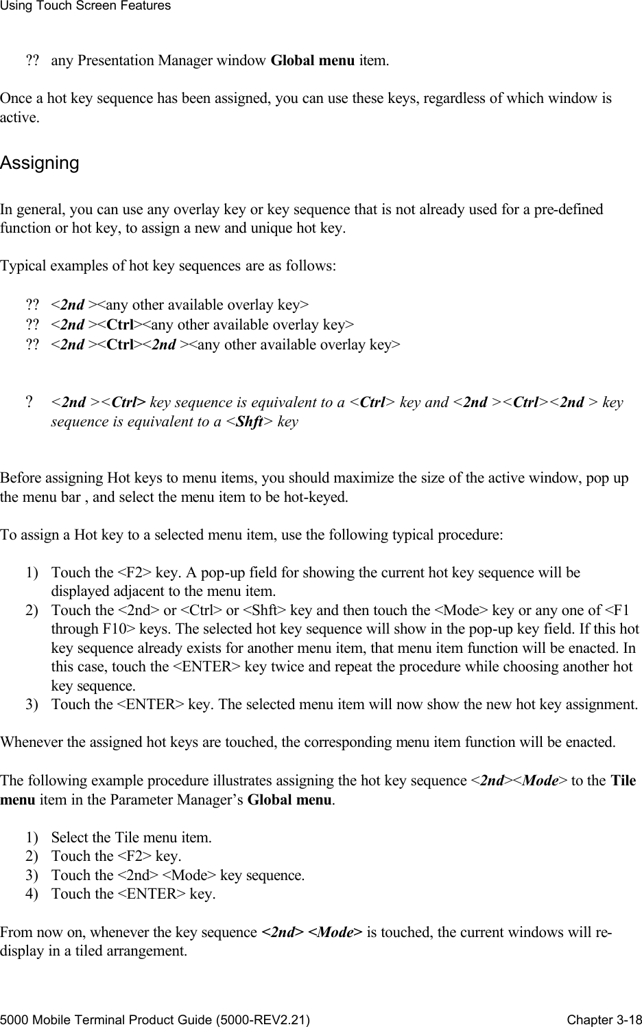
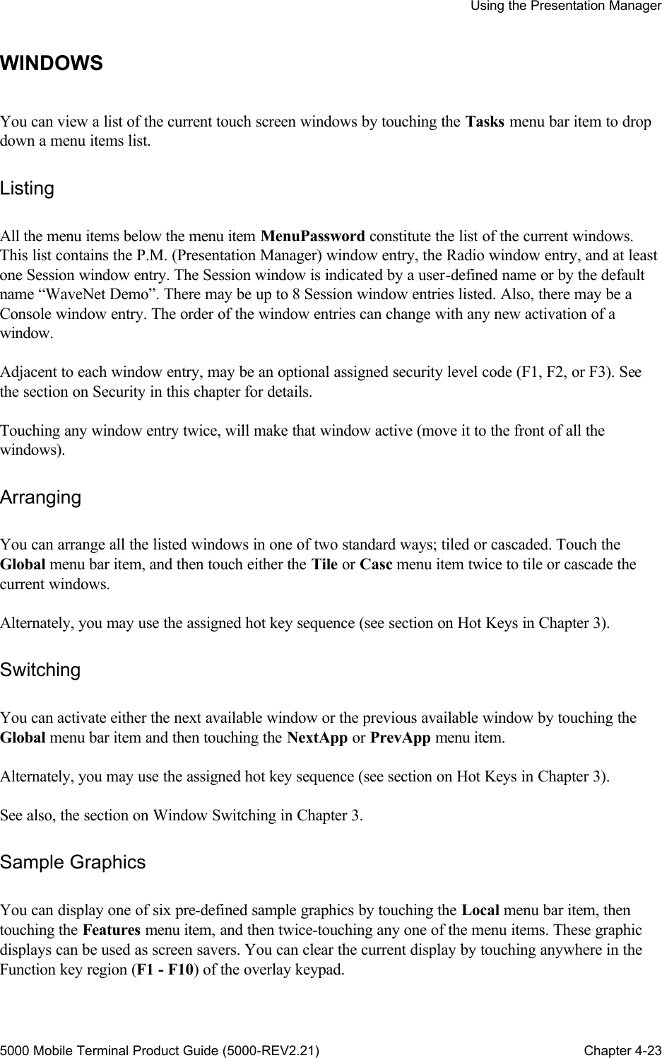
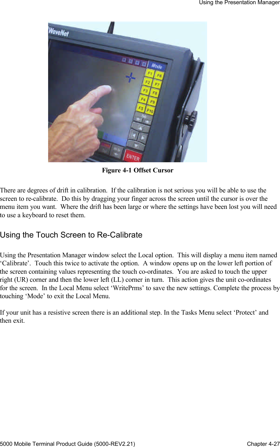
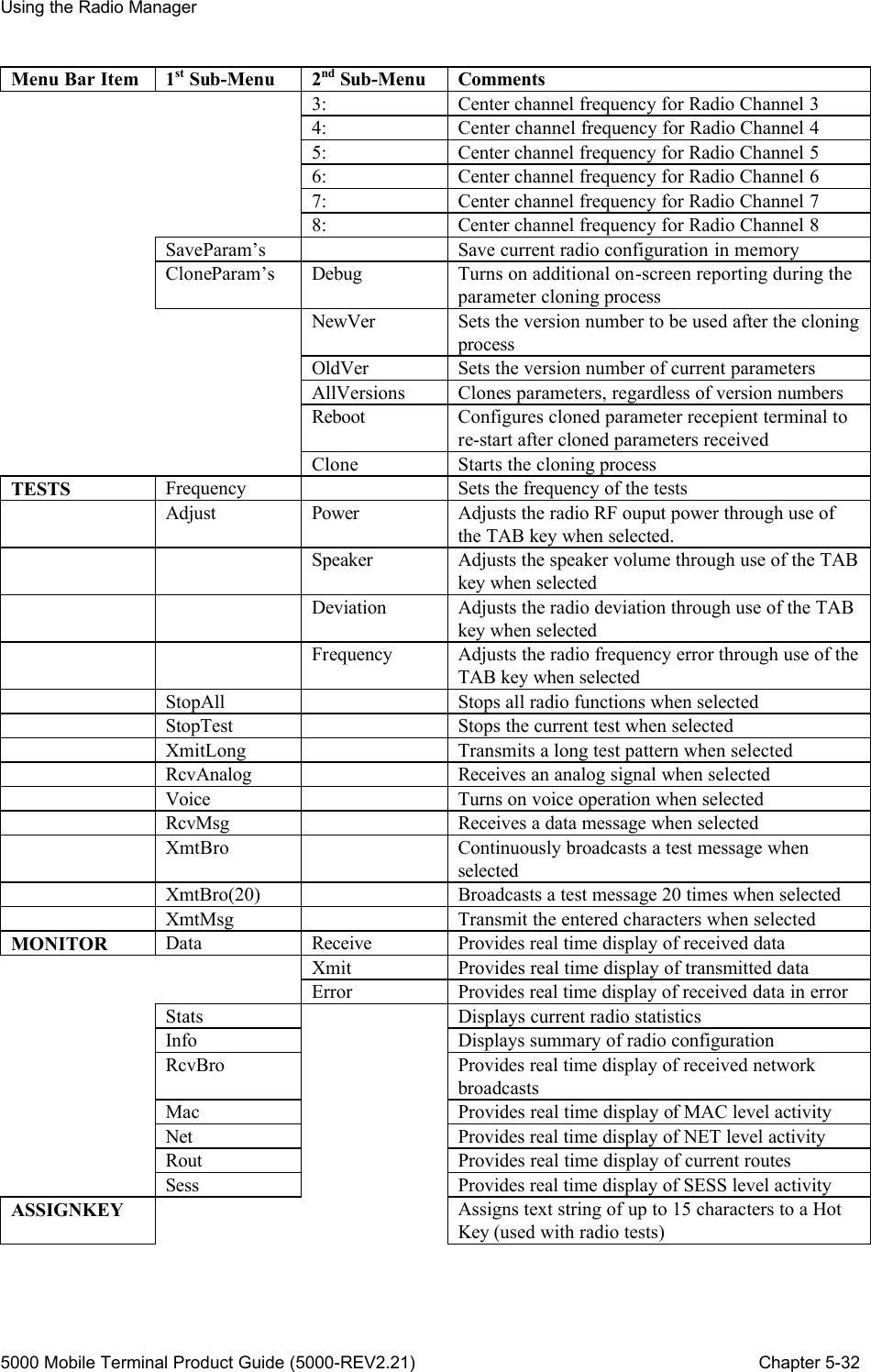
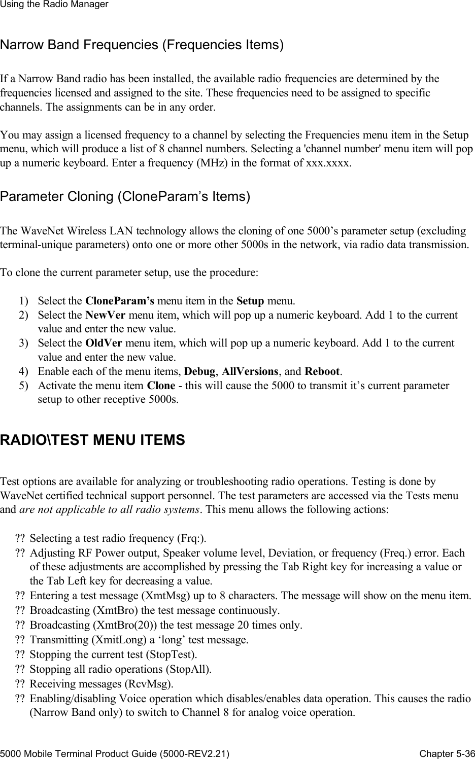
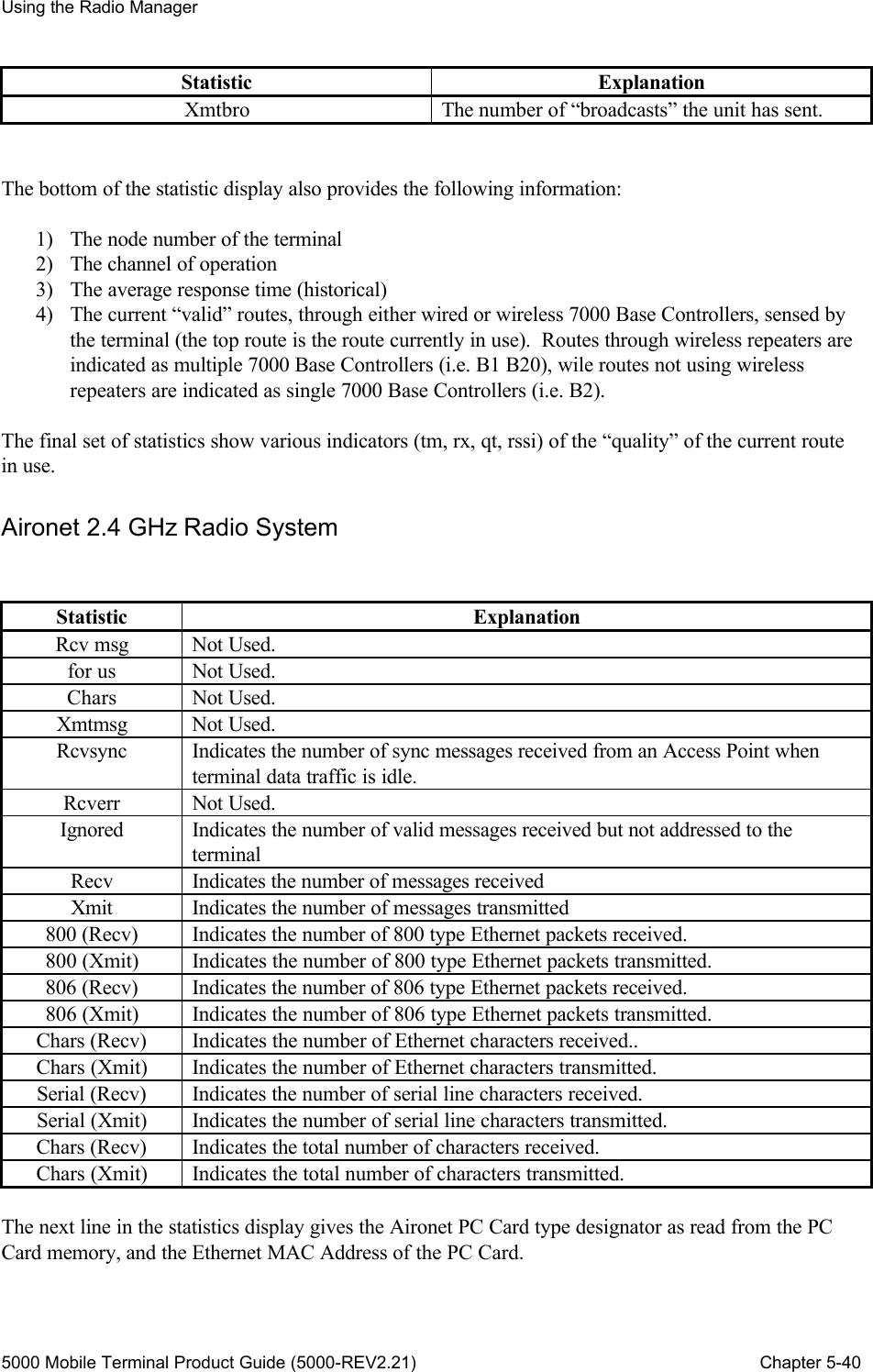
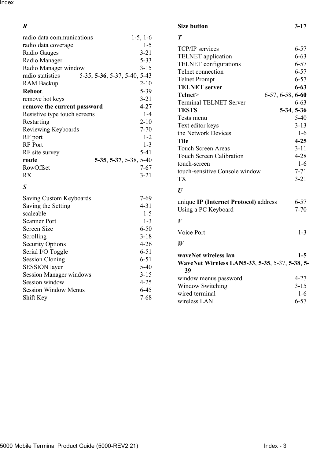
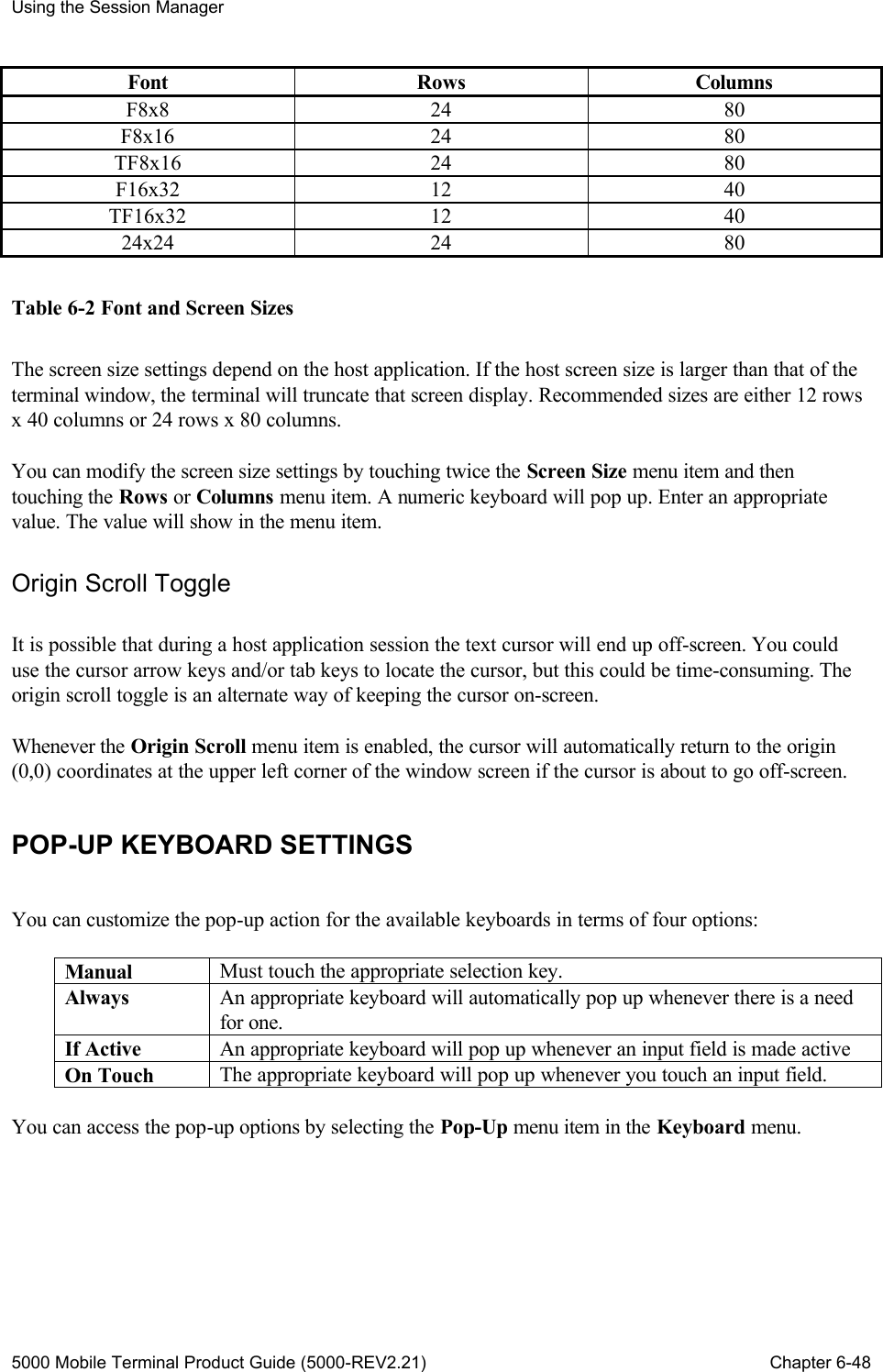
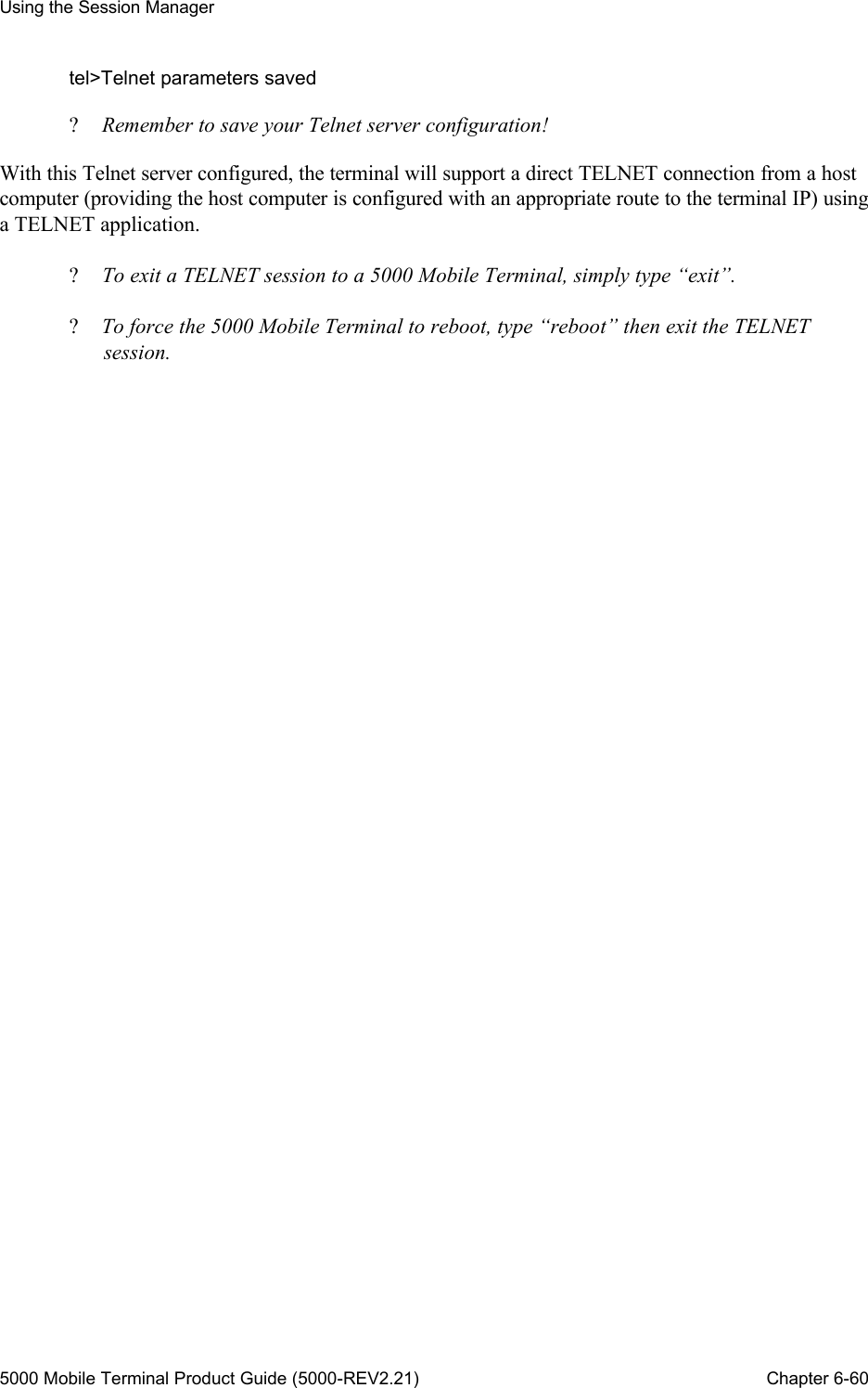
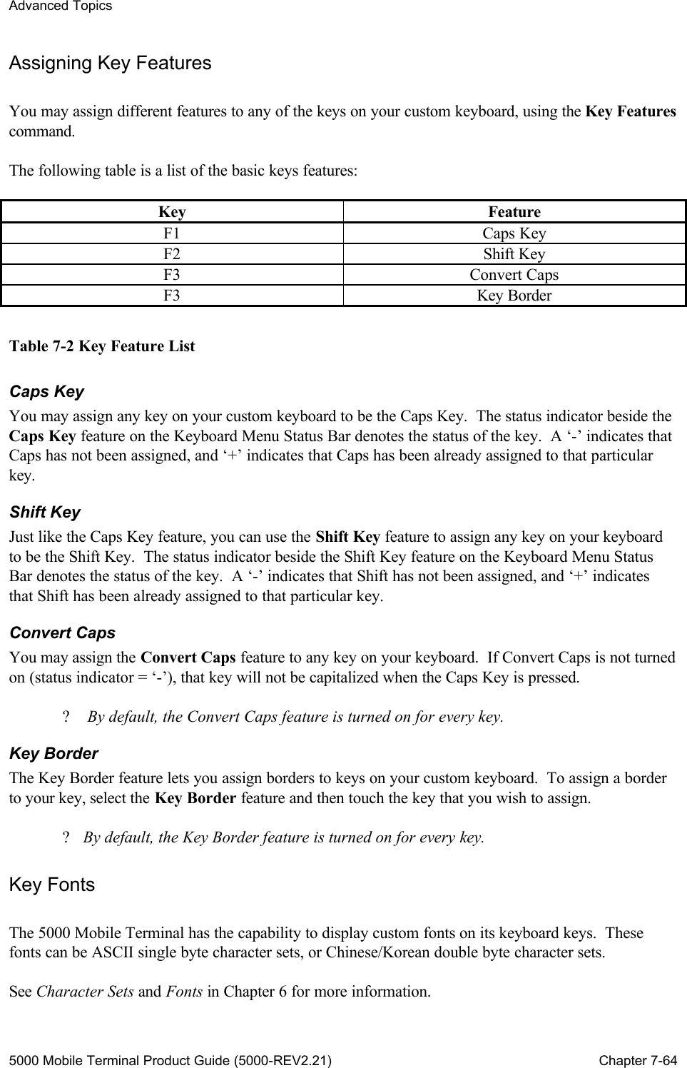
![Using the Session Manager 5000 Mobile Terminal Product Guide (5000-REV2.21) Chapter 6-43 Chapter 6 : Using the Session Manager This chapter explains how to utilize the Session Manager window menu functions of the 5000 Mobile Terminal unit. This chapter discusses the menu functions associated with: ?? Emulation Setting ?? Communication Settings ?? Display Settings ?? Pop-up Keyboard Settings ?? Barcode Tab Toggle ?? Cursor Captive Toggle ?? Serial I/O Toggle ?? Session Cloning ?? About Current Session The terminal supports a minimum of 1 session window and a maximum of 8 session windows. Multiple session windows are enabled via session window cloning. Each window supports an identical menu structure. Each window can be assigned a user-defined name. SESSION WINDOW MENUS A Session Manager window supports a menu structure consisting of a pop-up menu bar and a hierarchy of drop-down lists of menu items. You can touch the <Mode> key to pop up the menu bar. See the section on ‘Menu Navigation’ in Chapter 3 for general operational details. The following outline illustrates the menu bar and the scope and organization of the menu item options. Setup About Emulation Ver WaveNet Node VT220 Sess Unix Communication Service 5250 TN5250 3270 TN3270 Telnet PC Link PC Link[2]](https://usermanual.wiki/WaveNet/WL7412-450.WaveNet-5000-Mobile-Terminal-Product-Guide/User-Guide-164956-Page-55.png)
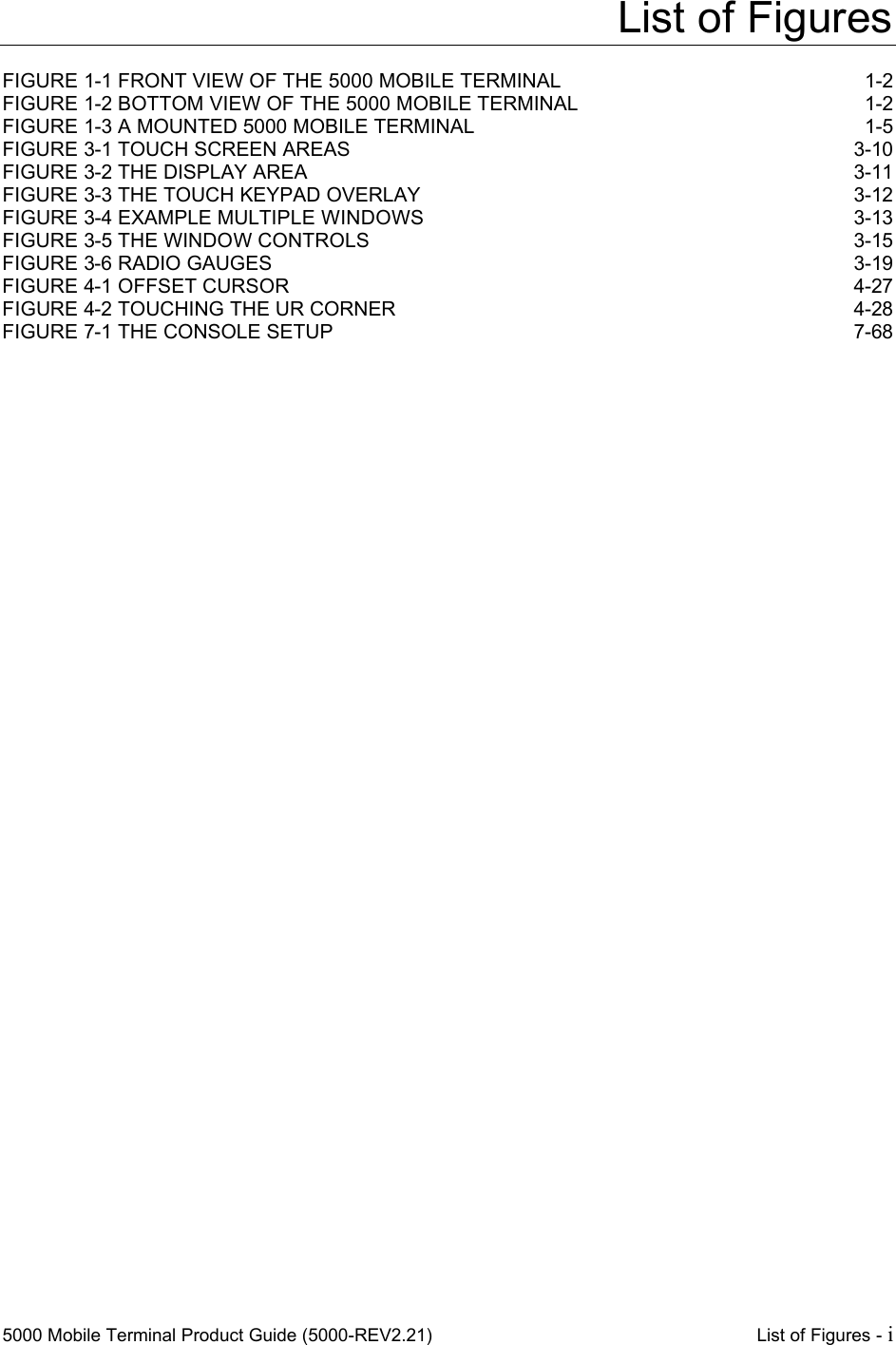
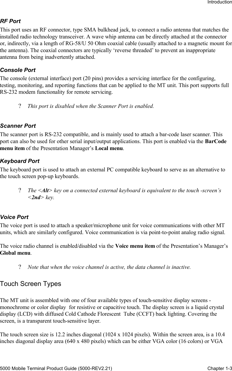
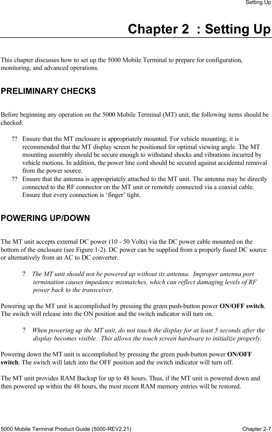
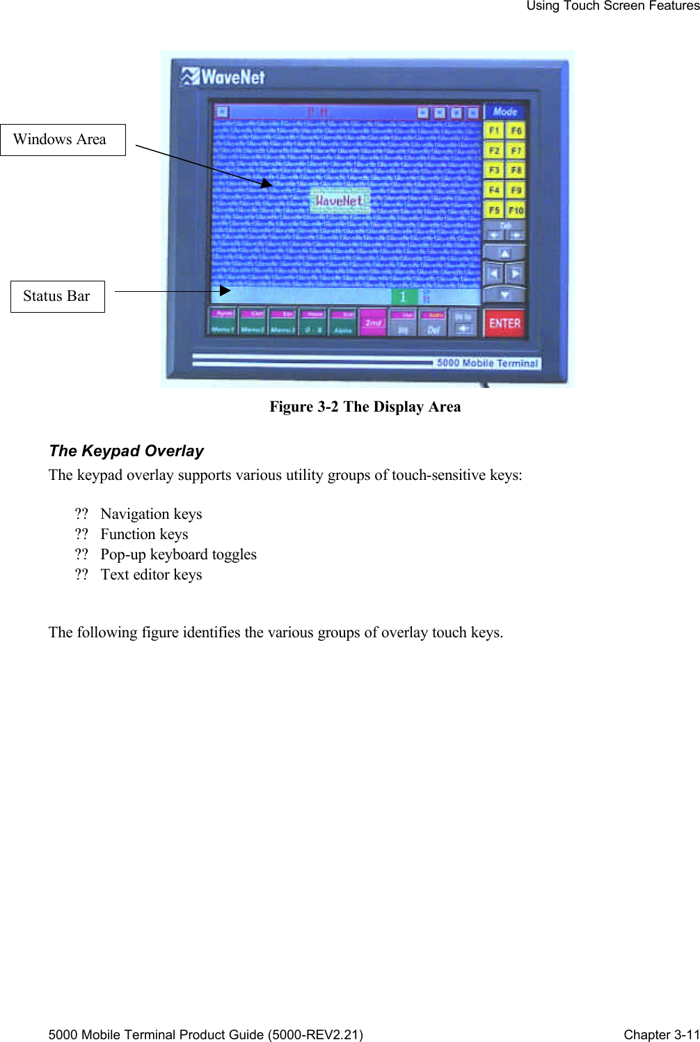
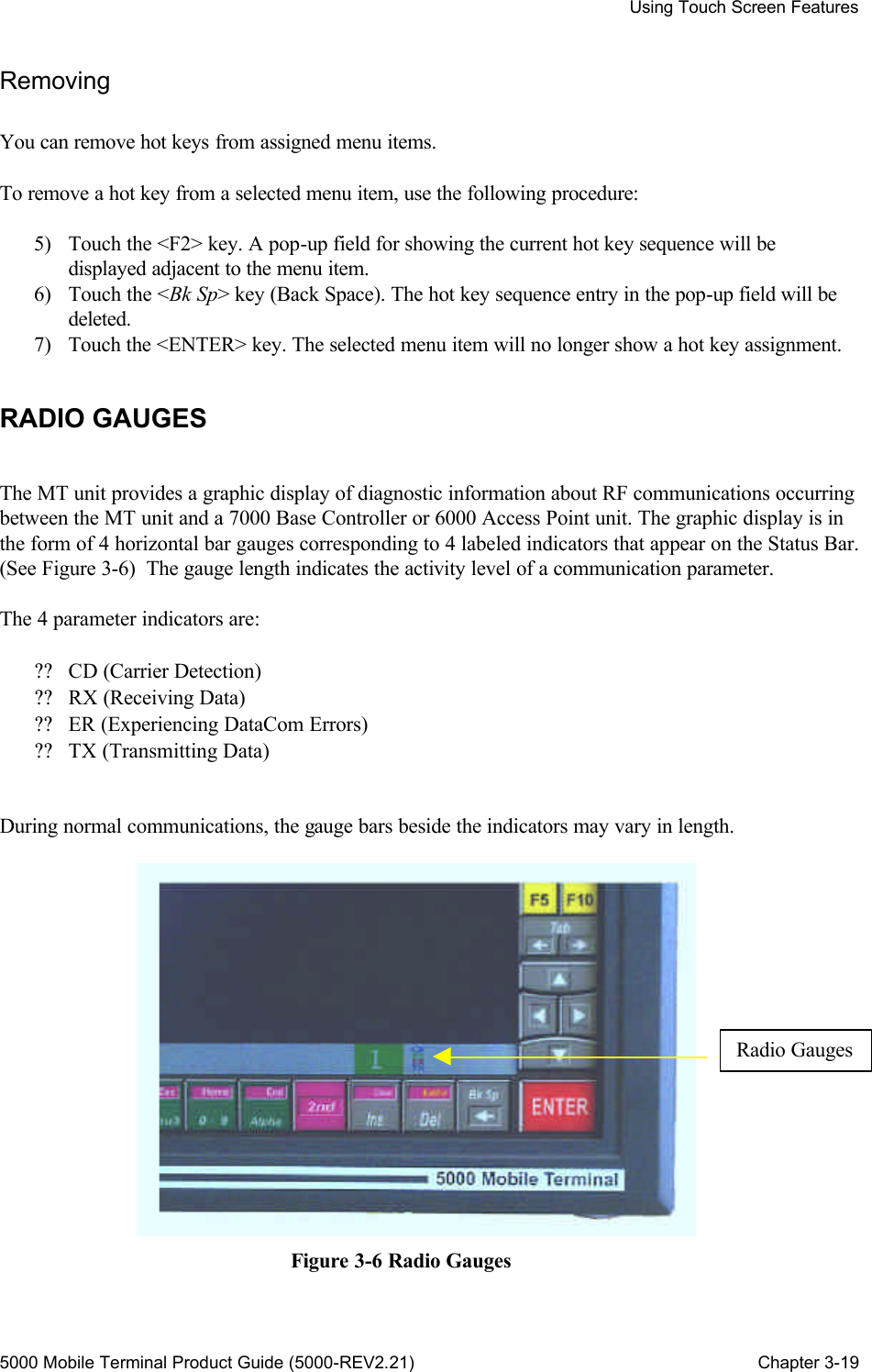
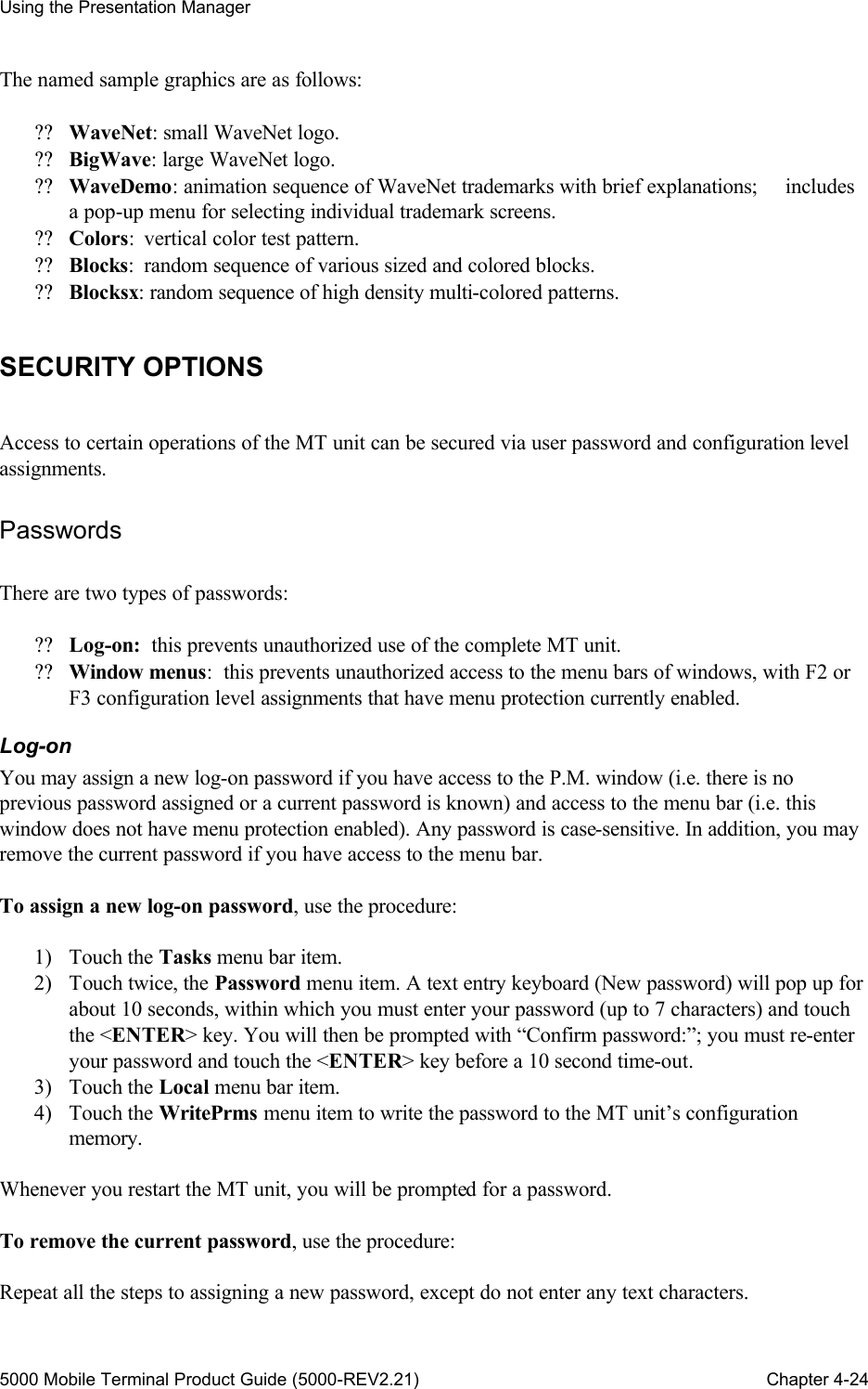
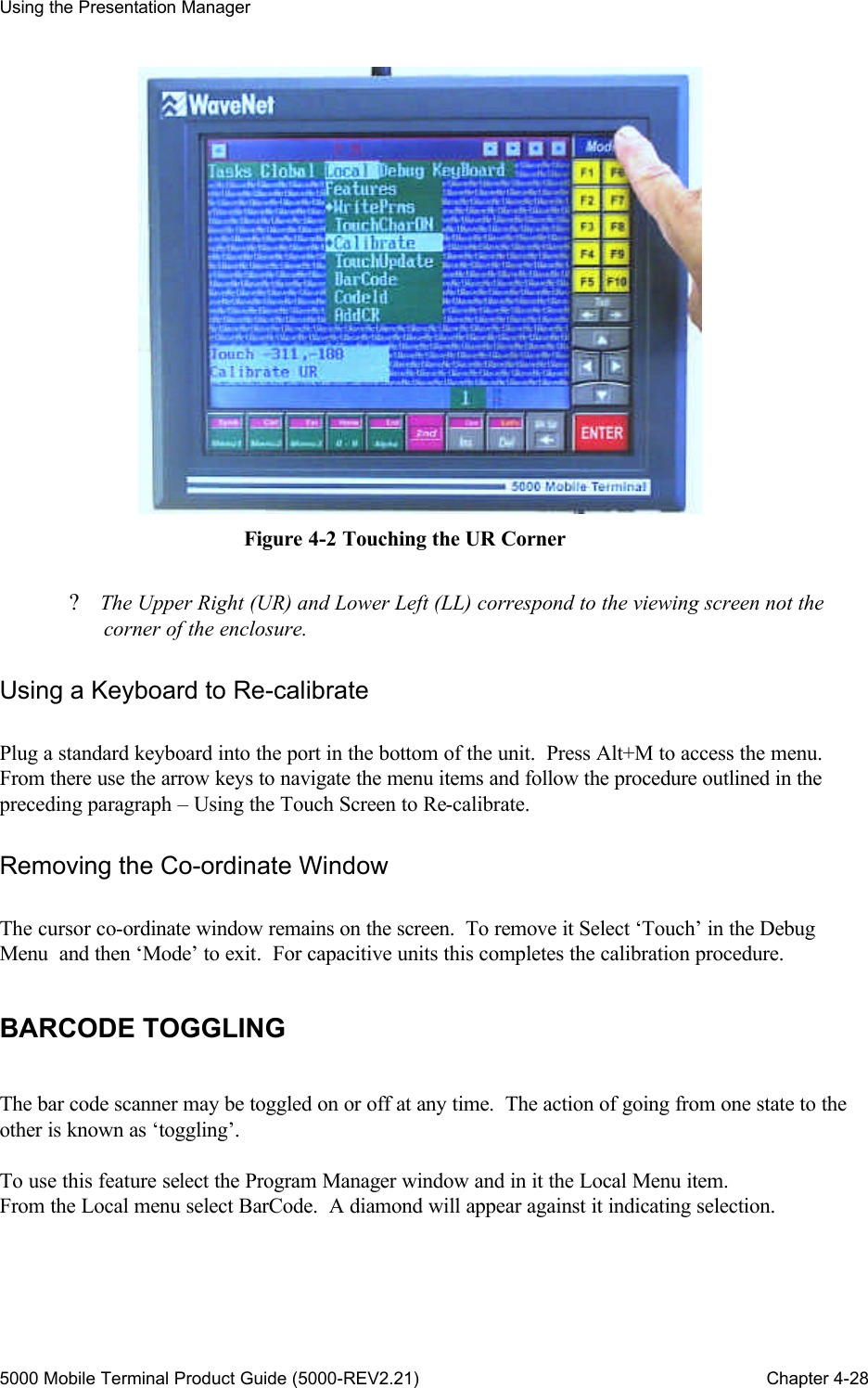
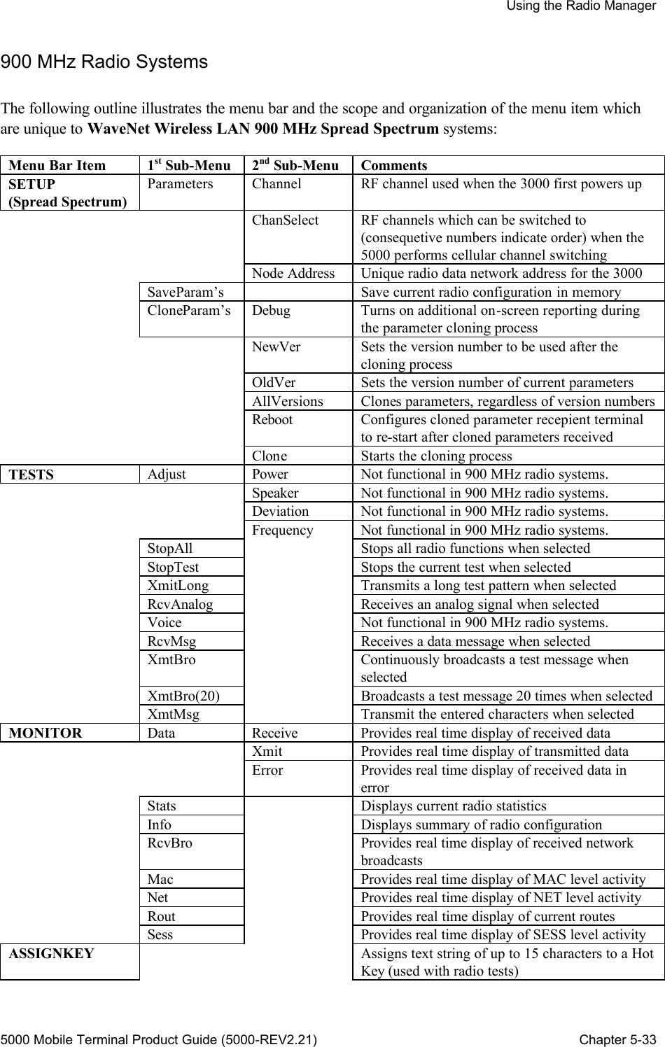
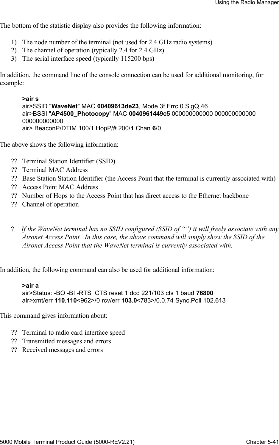
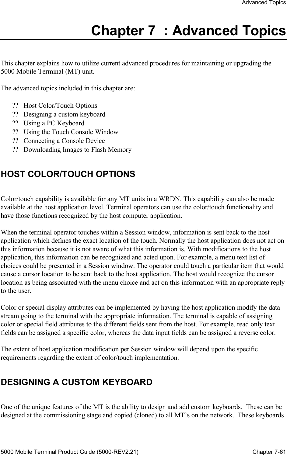
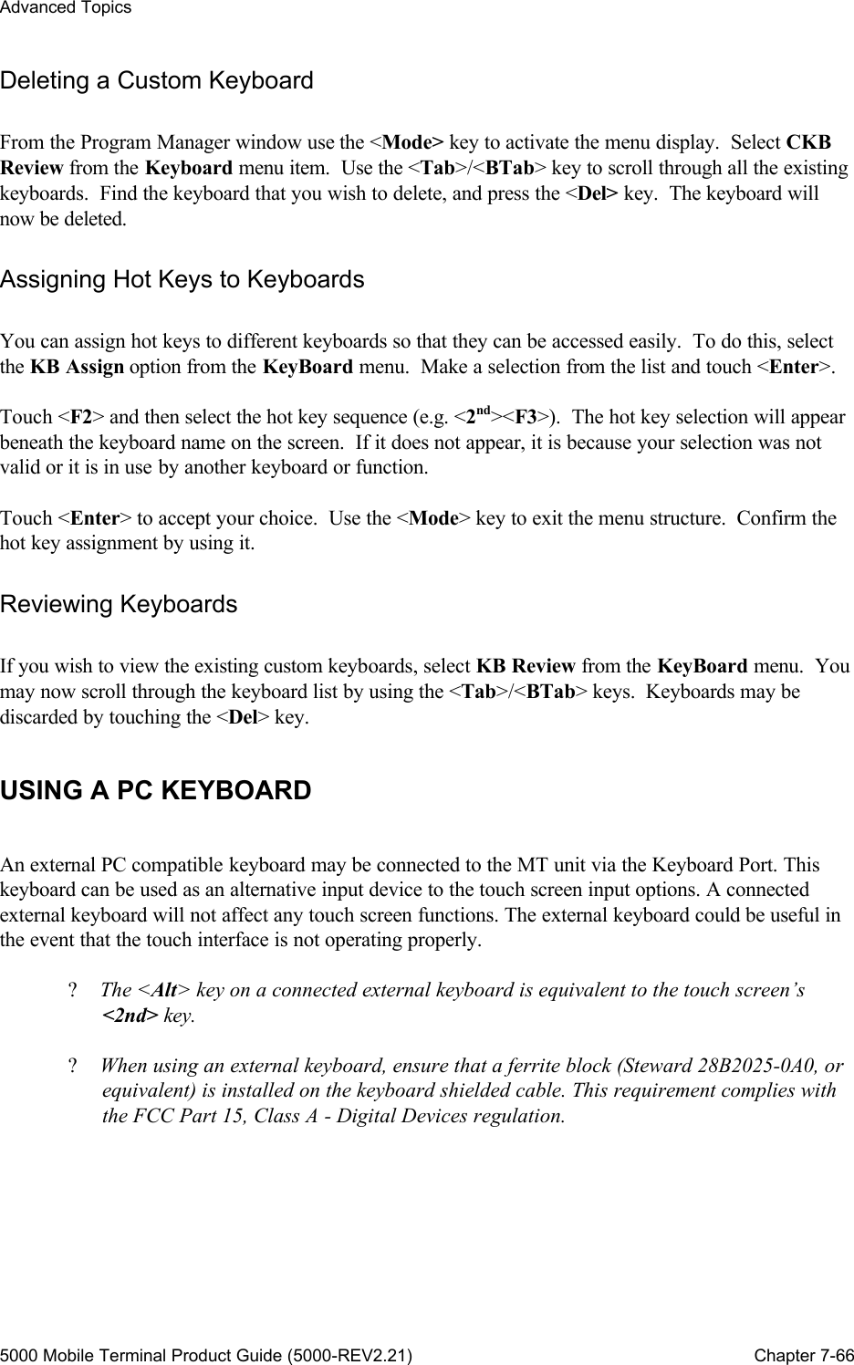
![Using the Session Manager 5000 Mobile Terminal Product Guide (5000-REV2.21) Chapter 6-44 PC Link[3] SLP-TCP Demo Session Copy Title Rename Delete Host ID = 0 8 Bit = Yes Display Page Caching Character Set ASCII Chinese Korean Font F8x8 F8x16 TF8x16 F16x32 TF16x32 Korean Chinese Font Map F8x8 =1 F8x16 =2 TF8x16 =3 F16x32 =4 TF16x32 =5 Korean =0 Chinese =6 Screen size Rows =25 Columns =80 Origin Scroll Keyboard Pop-up Manual Always If Active On Touch Barcode Tab Cursor Captive Other Serial I/O = NO](https://usermanual.wiki/WaveNet/WL7412-450.WaveNet-5000-Mobile-Terminal-Product-Guide/User-Guide-164956-Page-56.png)
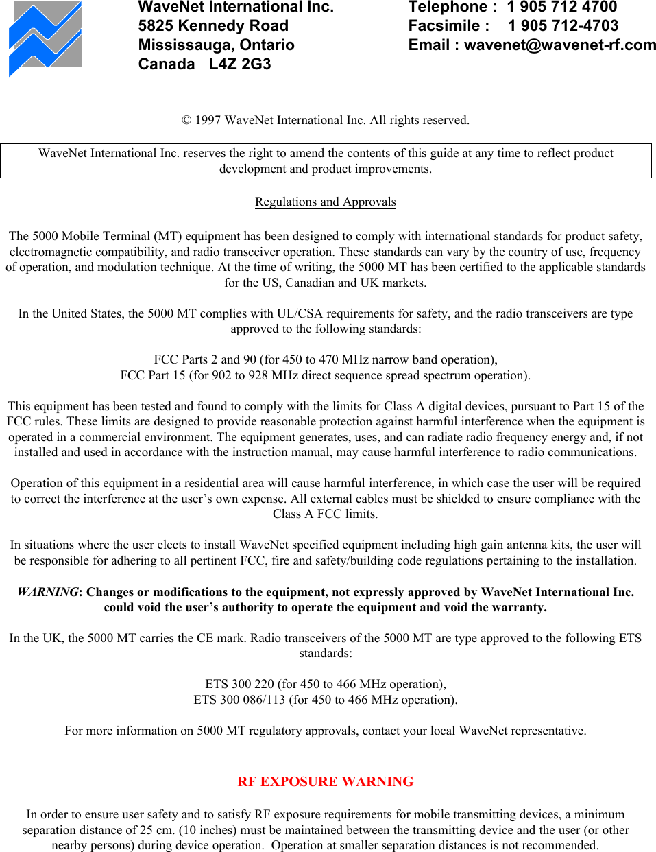
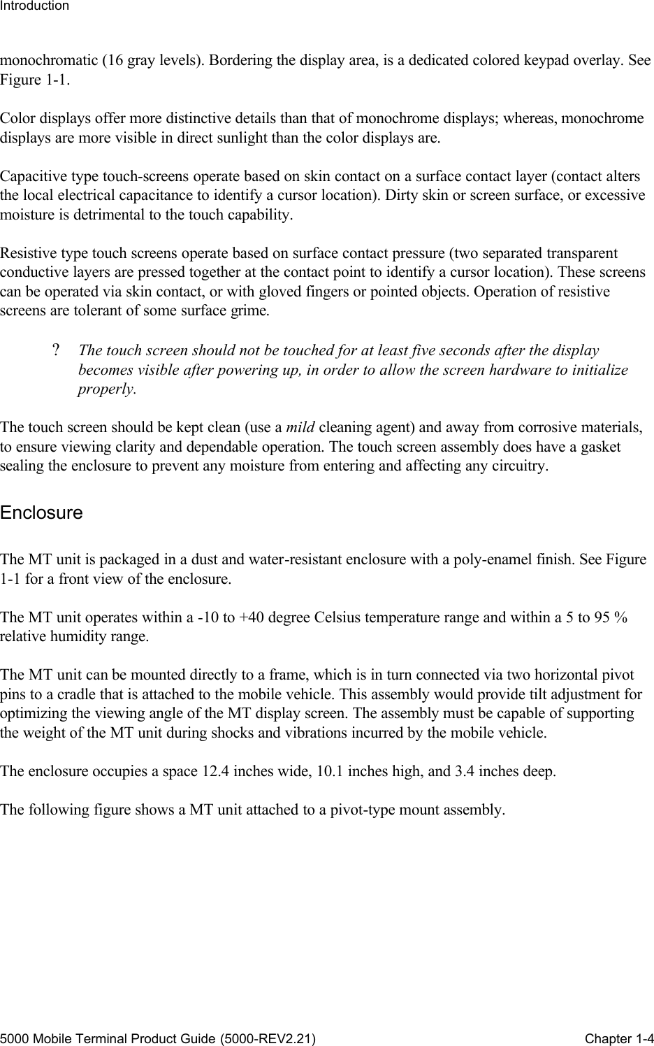
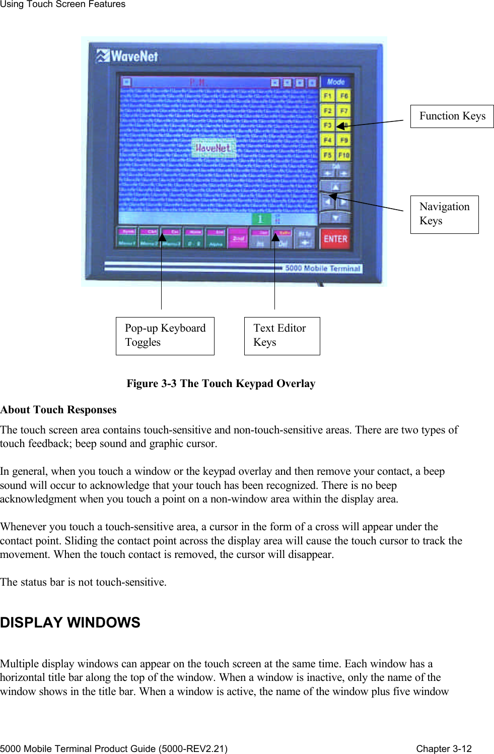
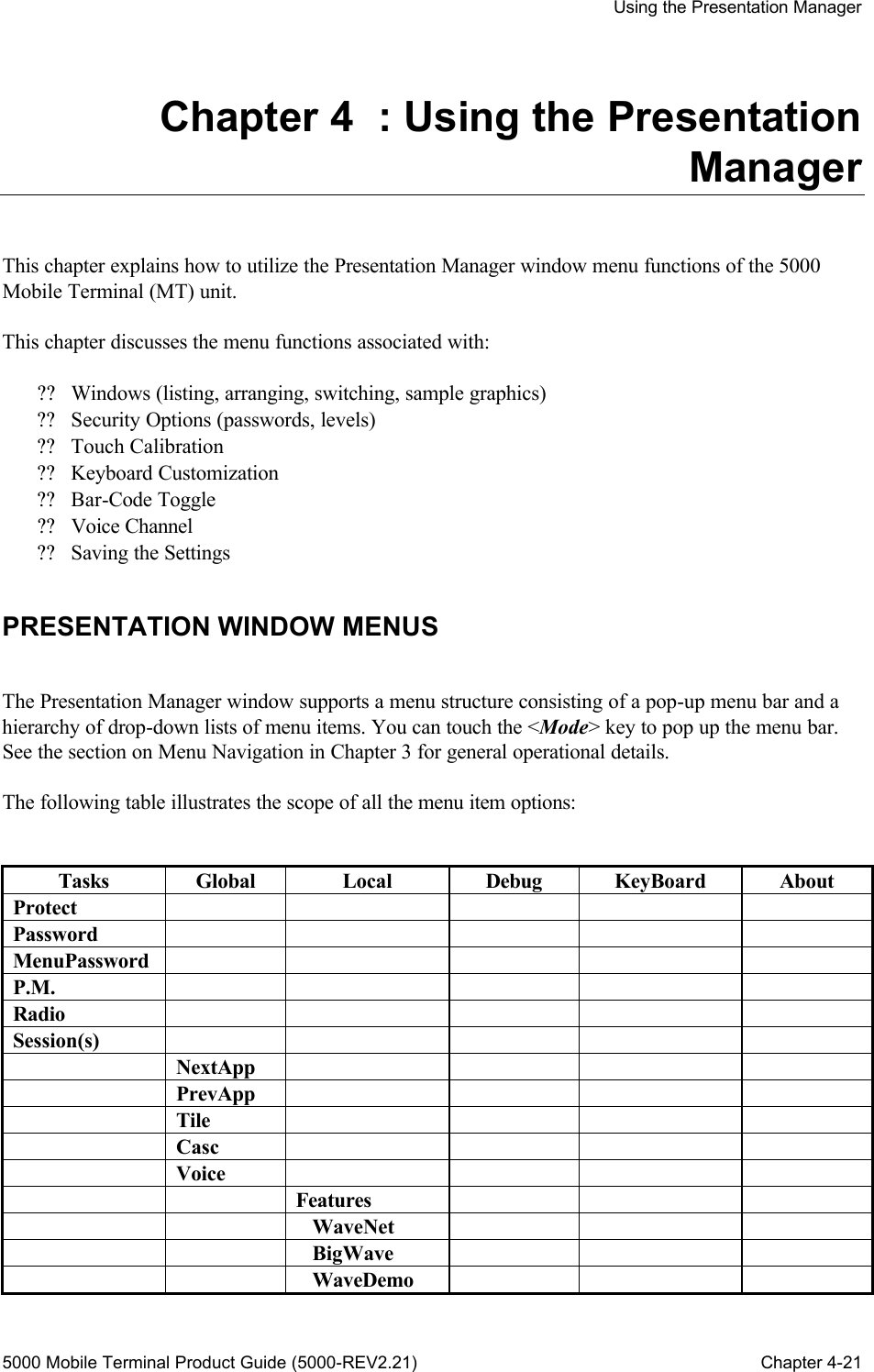
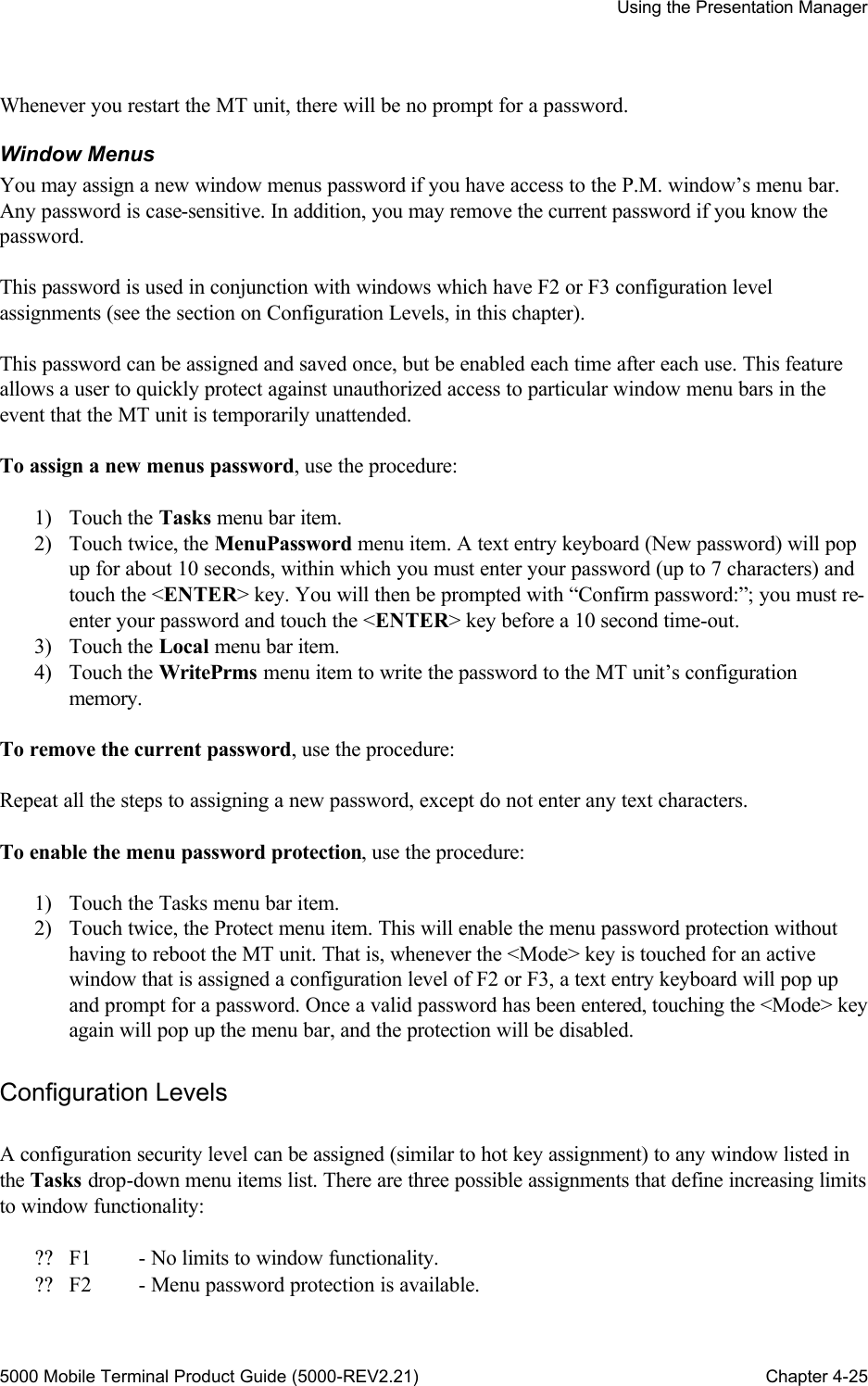
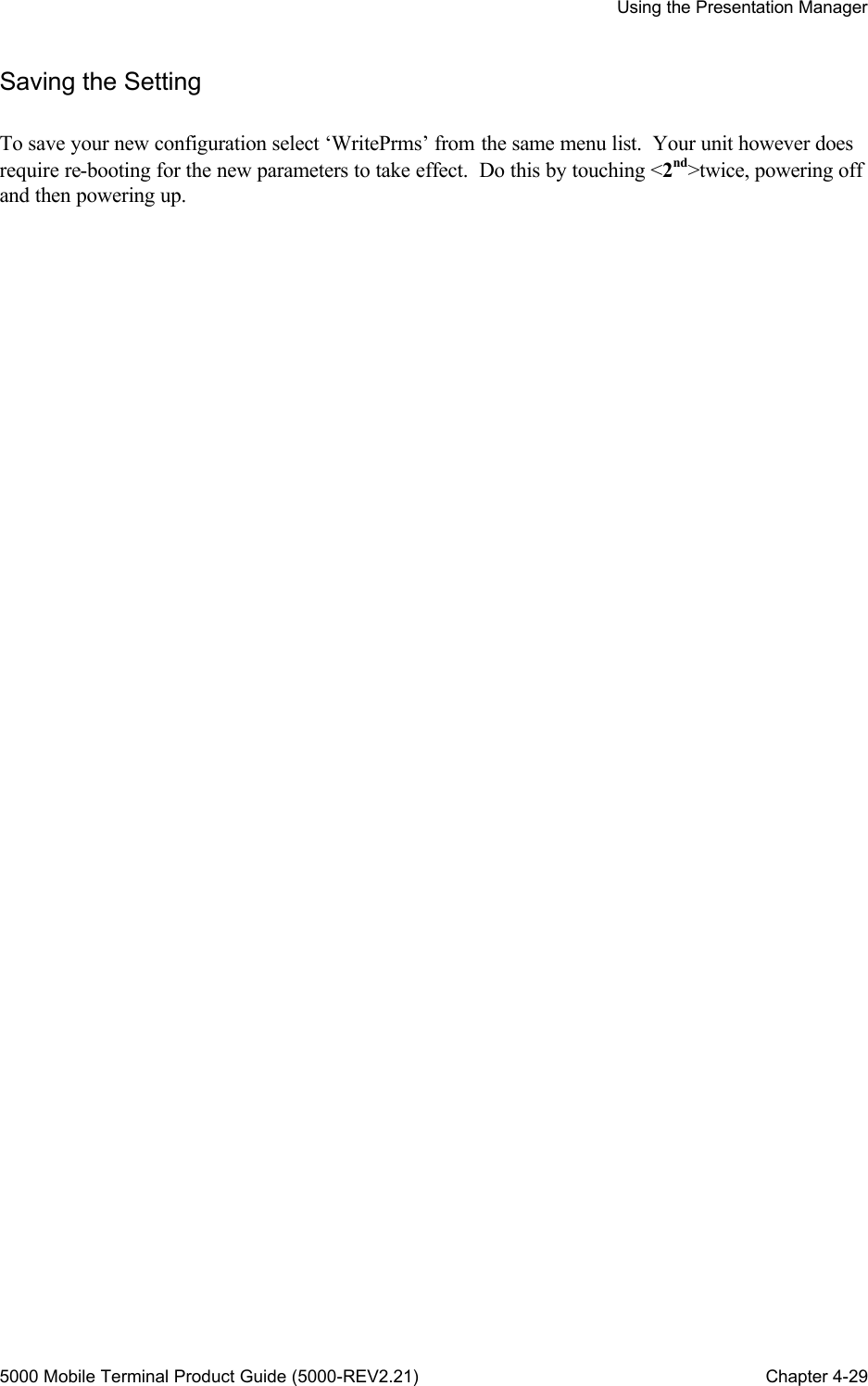
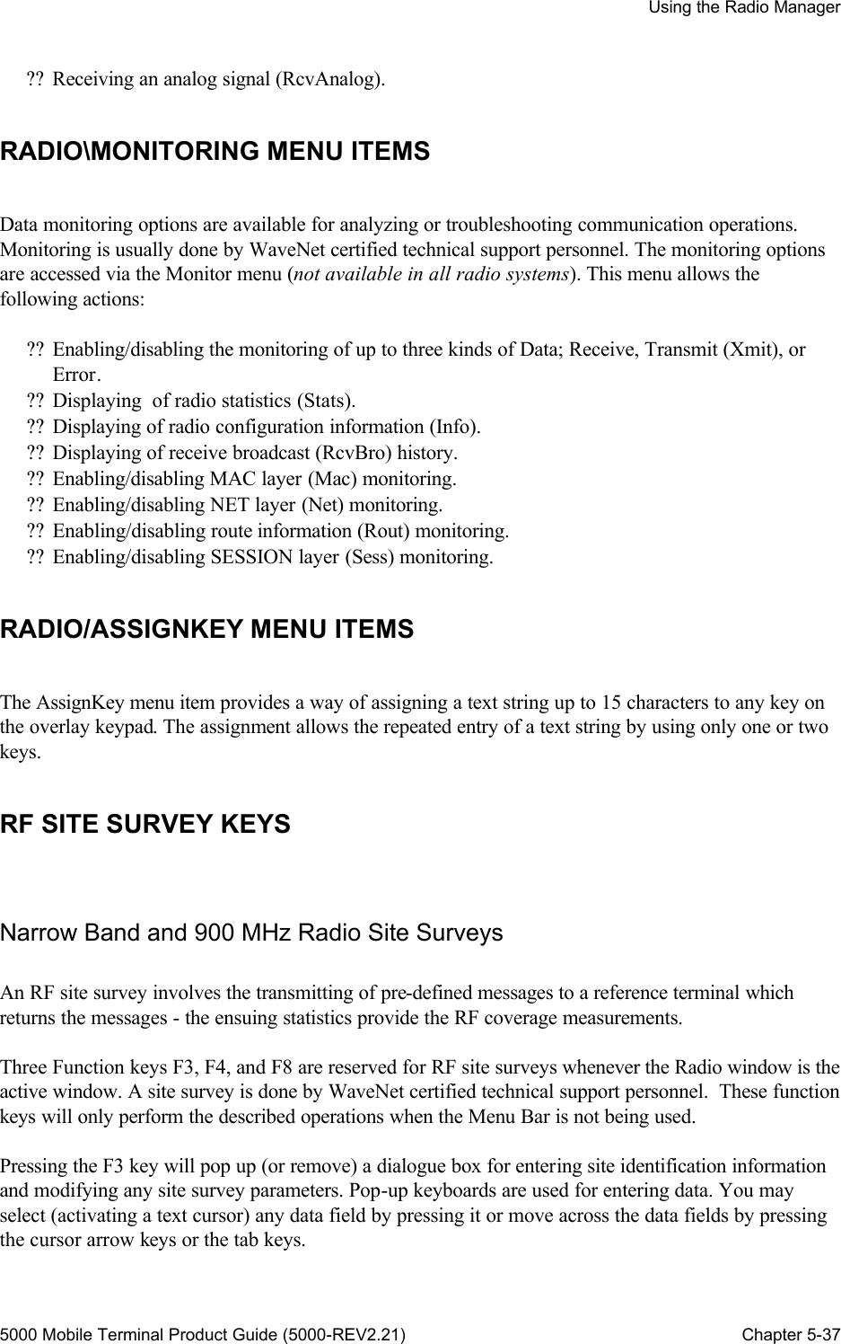
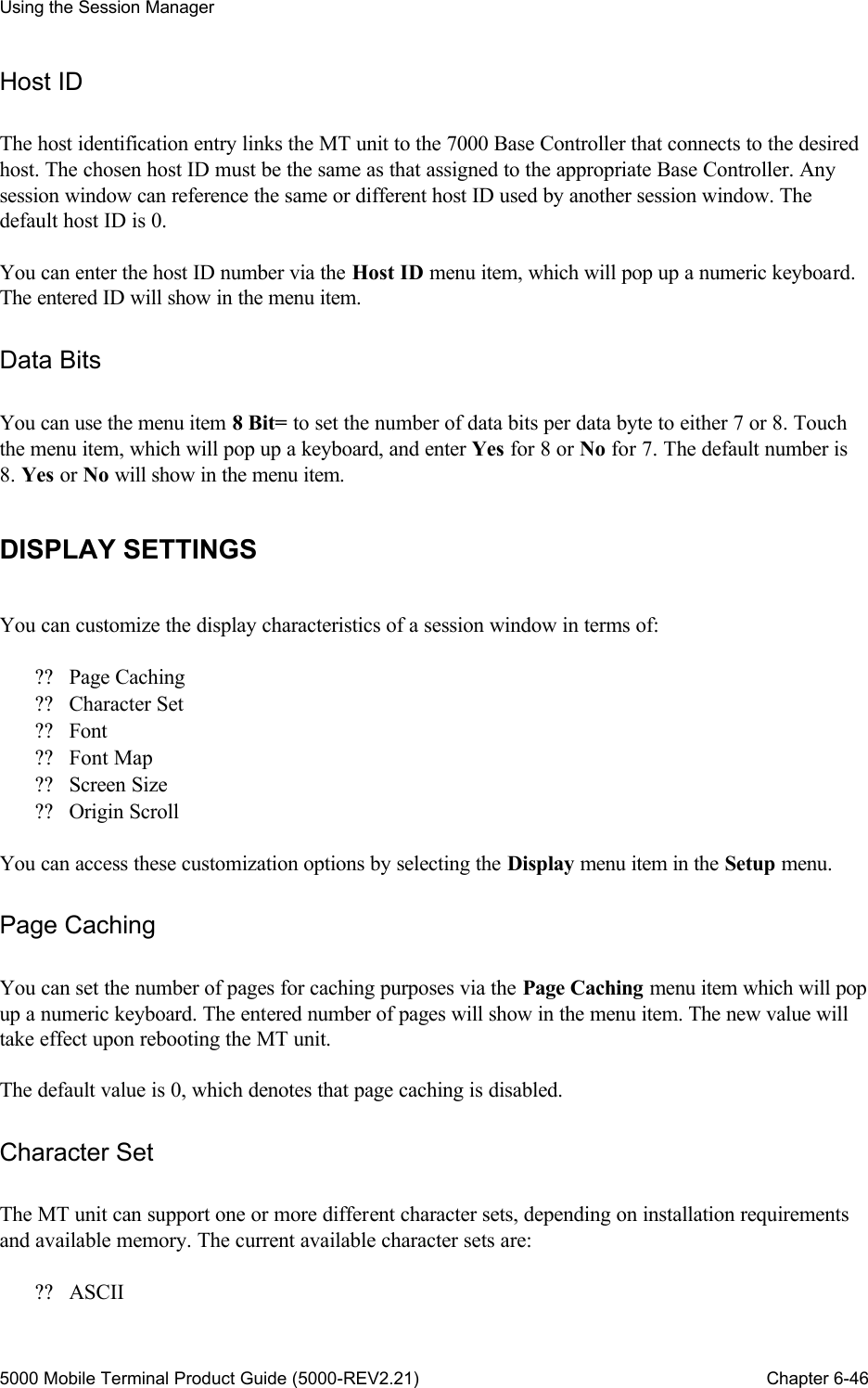
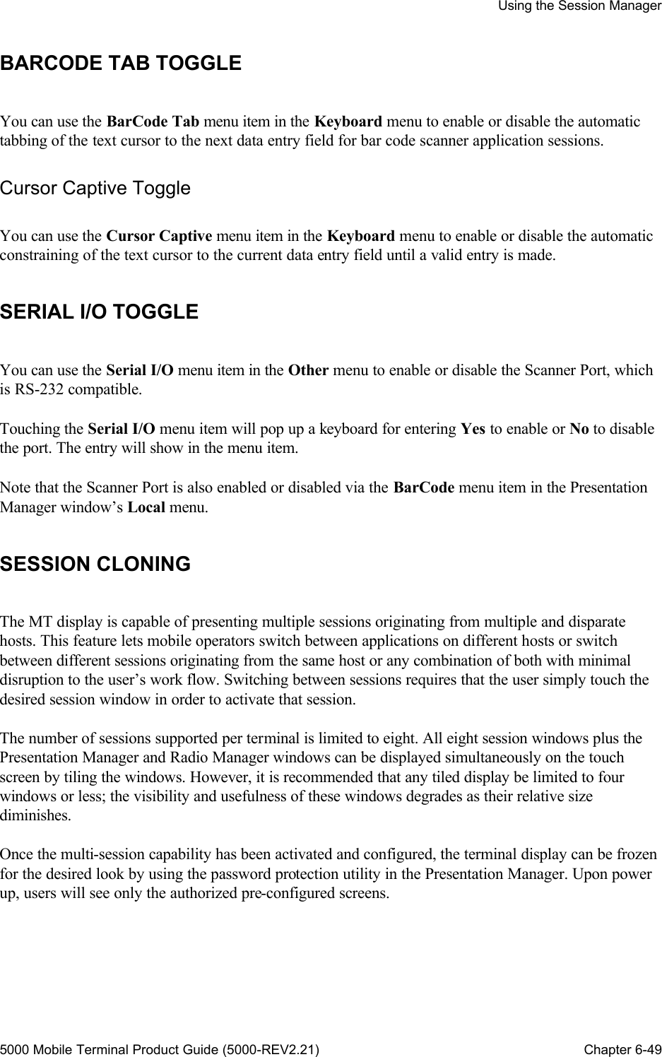
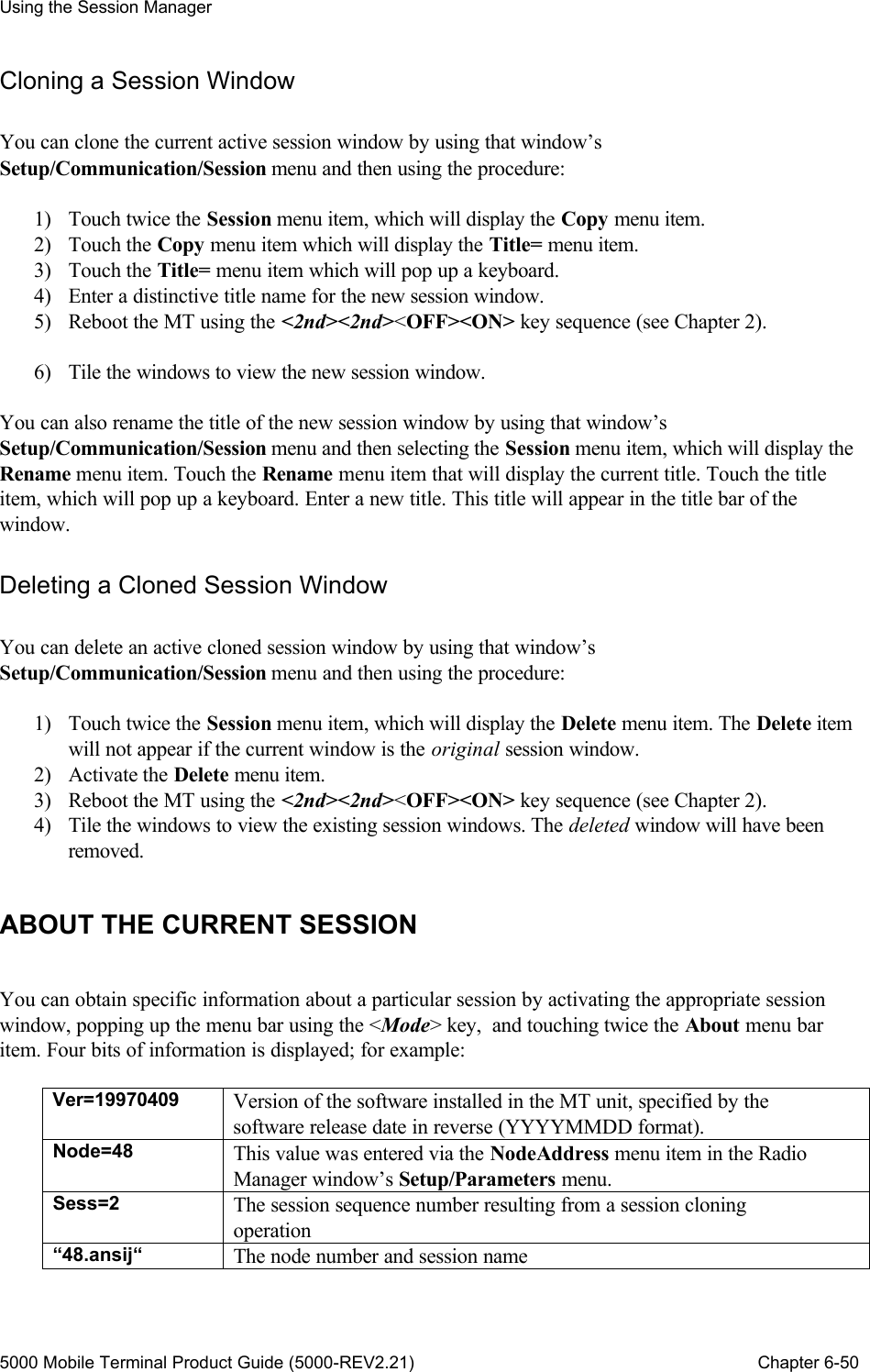
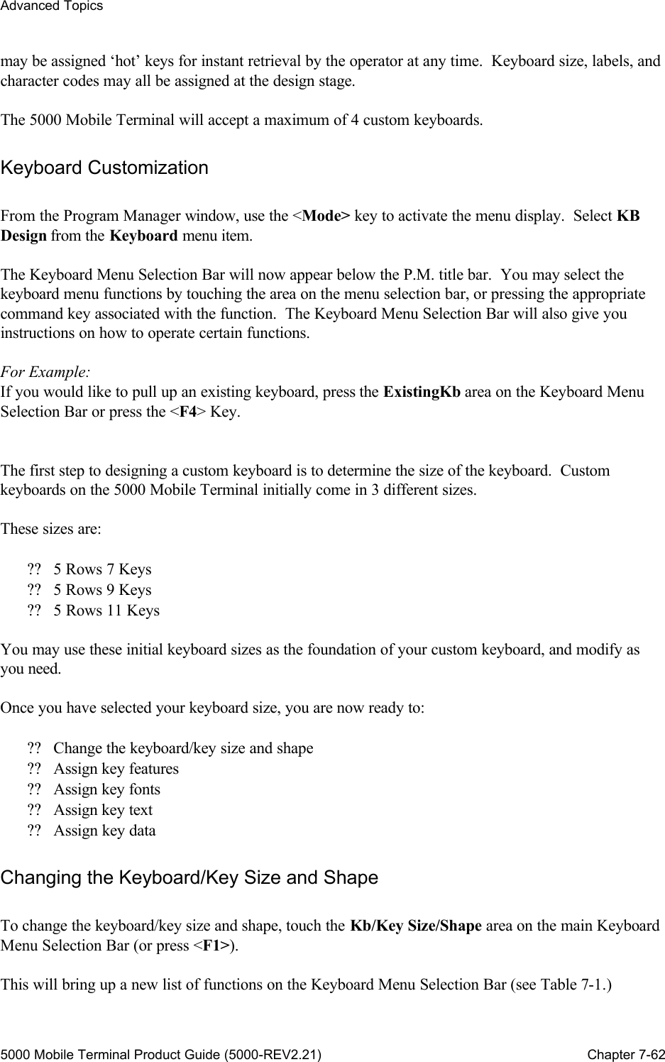
![Using the Session Manager 5000 Mobile Terminal Product Guide (5000-REV2.21) Chapter 6-45 Table 6-1 The Session Manager Window Menu Structure EMULATION SETTING The MT unit supports three types of host application session terminal emulators: ?? WaveNet (ANSI) ?? VT220 ?? Unix You can select one of the emulators by selecting the Emulation menu item in the Setup menu, and then touching twice the chosen emulation menu option. The VT220 emulation allows the Function keys F1 - F4 to be used for the VT220 PF1 - PF4 keys. COMMUNICATION SETTINGS The communication settings for each session window involve: ?? Selecting the desired host communications service. ?? Entering the required host identifier. ?? Setting the number of data bits. You can access these settings by selecting the Communication menu item in the Setup menu. Host Service Touch the Service menu item to display a list of possible host services. Touch twice to enable one of the following communication services: ?? 5250 IBM 5250 data stream via SDLC/SNA. ?? TN5250 IBM 5250 data stream via TCP/IP/Telnet. ?? 3270 IBM 3270 data stream via SDLC/SNA. ?? TN3270 IBM 3270 data stream via TCP/IP/Telnet. ?? Telnet ANSI data stream via TCP/IP/Telnet. ?? PC Link ANSI data stream via RS-232/WaveNet SIOP, per host 1. ?? PC Link[2] ANSI data stream via RS-232/WaveNet SIOP, per host 2. ?? PC Link[3] ANSI data stream via RS-232/WaveNet SIOP, per host 3. ?? SLP-TCP ANSI data stream via TCP/IP/WaveNet SLP. ?? Demo ANSI data stream per WaveNet host simulation.](https://usermanual.wiki/WaveNet/WL7412-450.WaveNet-5000-Mobile-Terminal-Product-Guide/User-Guide-164956-Page-57.png)
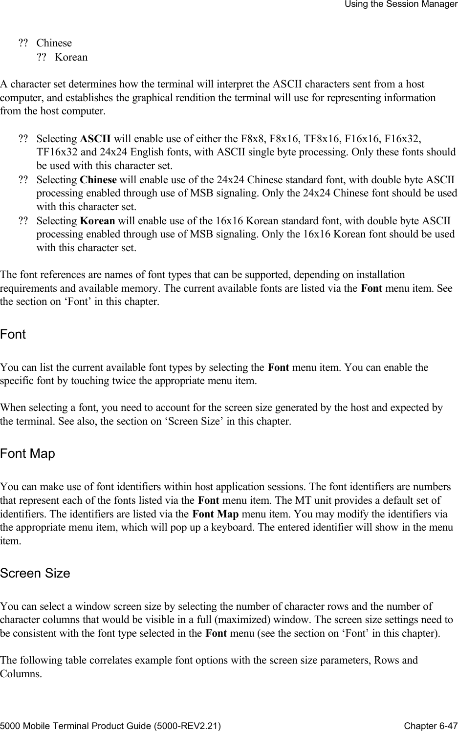
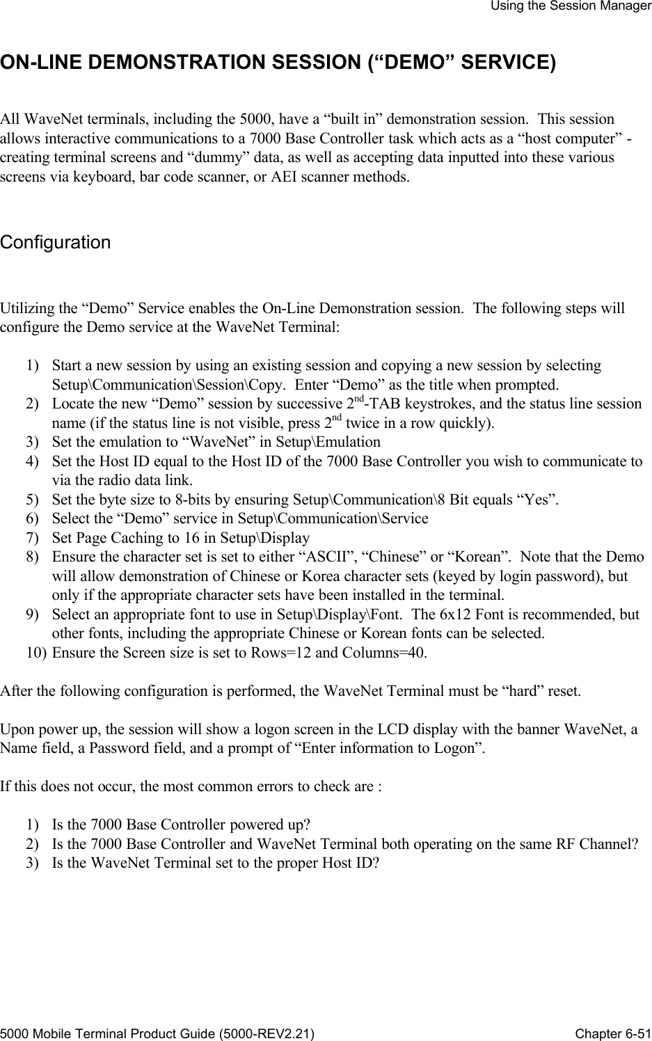
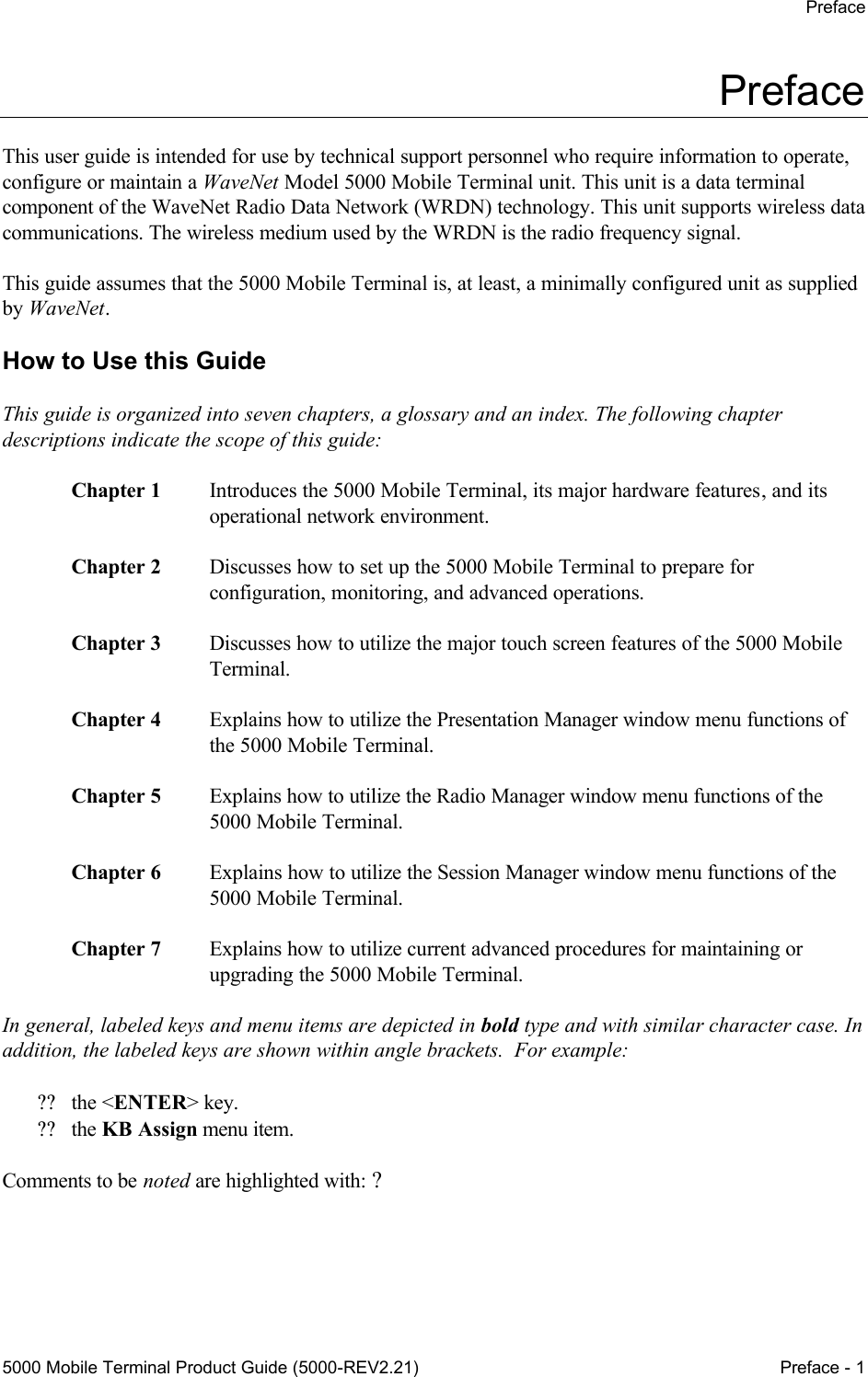
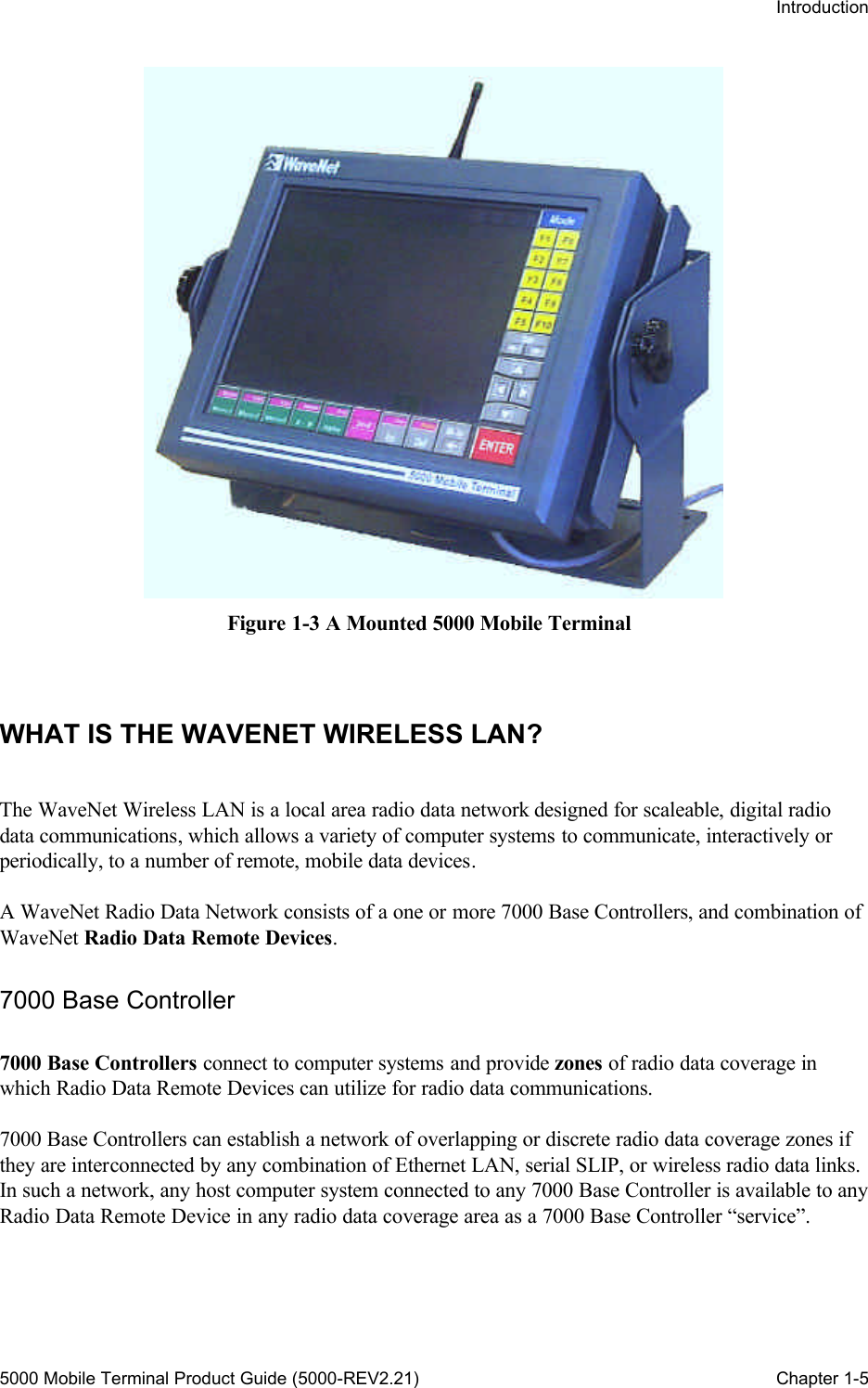
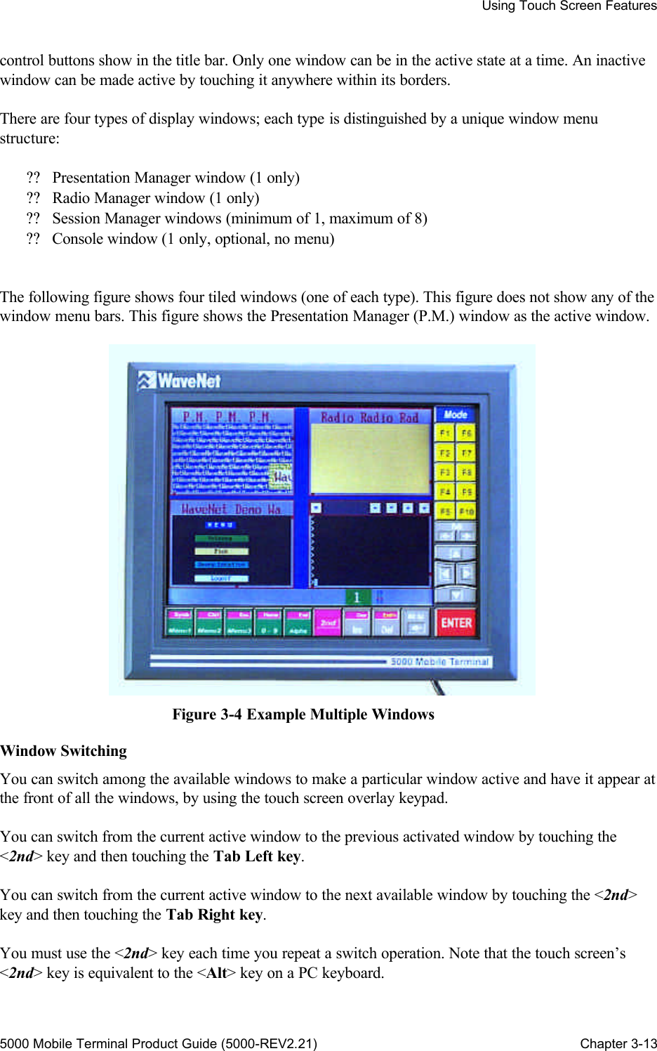
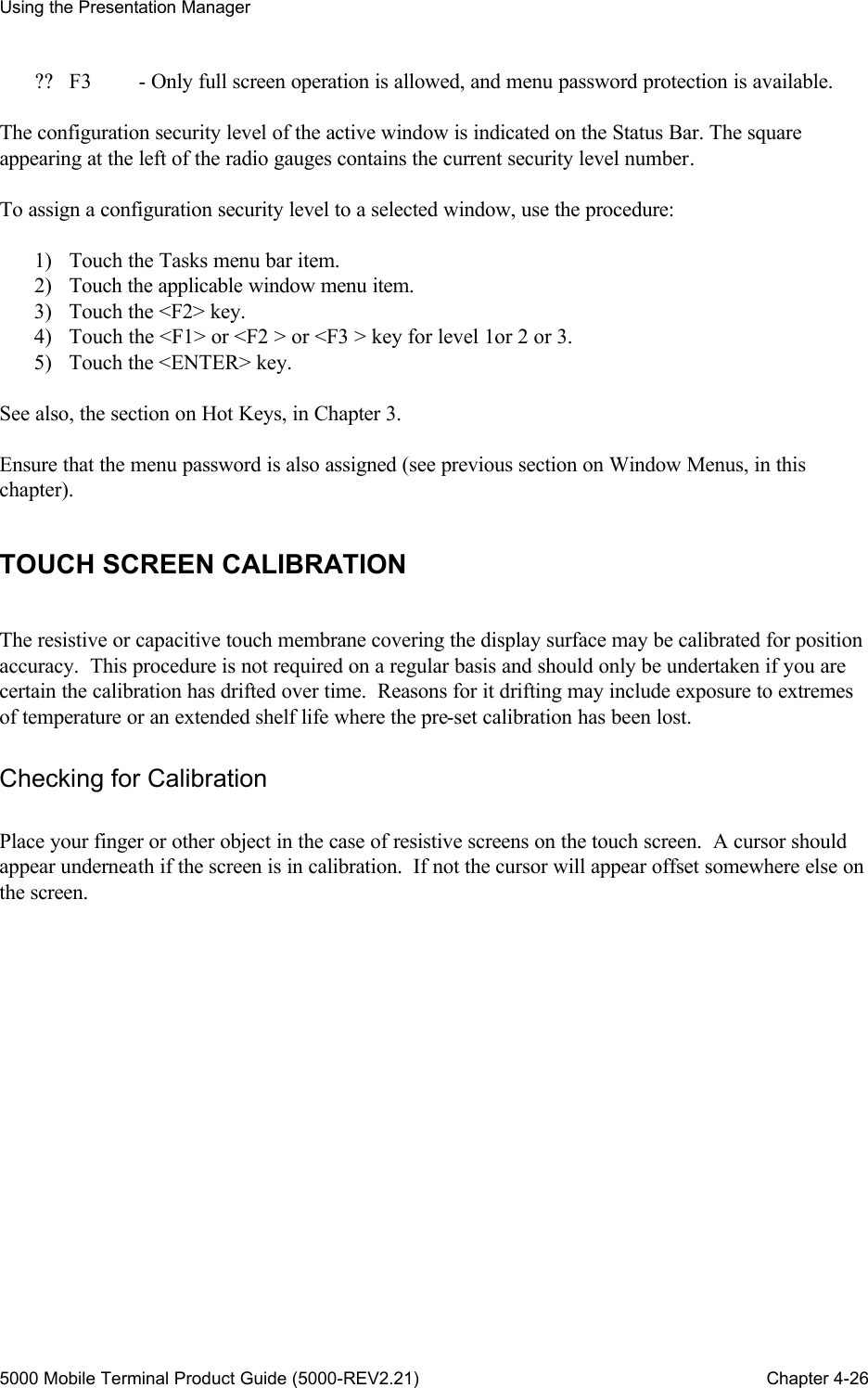
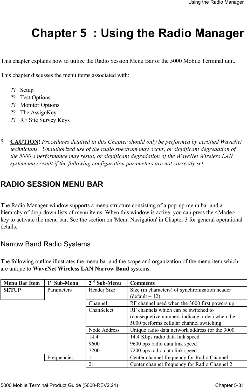
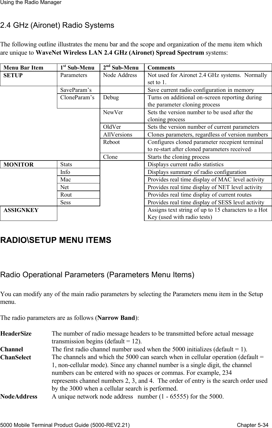
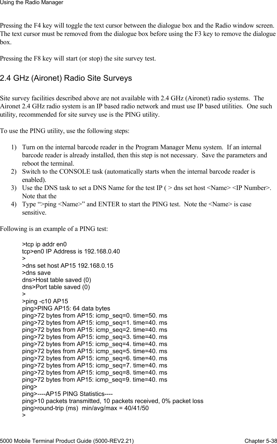
![Using the Session Manager 5000 Mobile Terminal Product Guide (5000-REV2.21) Chapter 6-55 Setting the Terminal IP Number Every node on an Ethernet TCP/IP network requires a unique IP (Internet Protocol) address. In the 2.4 GHz radio system which uses Local Telnet Sessions, the terminal is a node, and requires a unique IP address, formatted as y.x.x.x, where 1 <= y <= 239 and 0 <= x <= 254. To assign an IP address, use the command: > tcp ip addr en0 [y.x.x.x] To set the IP address for the interface. For example, to assign the IP address 7.7.7.3 to the Ethernet interface (known as en0), use the command: > tcp ip addr en0 7.7.7.3 The IP address assignment takes effect after the terminal is rebooted. To store the IP address to the BC unit’s configuration memory, use the command: > tcp param save To save the current TCP/IP parameter settings. Using DNS Services DNS (Dynamic Name Service) allow mnemonic text descriptions to be used instead of IP addresses. For example, instead of typing in an IP number to connect to a ANSI/VT220 compatible computer system: Telnet> 192.168.0.1 <Enter> The following mnemonic text could be entered: Telnet> server <Enter> The DNS server functions are located in the “dns” task which can be accessed using the console task or external console connector. The following command shows the Help facilities available with the command: >dns ? dns>Valid commands are: dns>assign or set: assign [host|port] name number dns>get: get assignments dns>clear or zero: clear [host|port|both] name tables dns>debug or -d: set debug level dns>def*ault: restore default tables dns>res*tore or read: restore [host|port|both] name tables dns>save or write: save [host|port|both] name tables > To set and save a mnemonic name for an IP number, use the following command:](https://usermanual.wiki/WaveNet/WL7412-450.WaveNet-5000-Mobile-Terminal-Product-Guide/User-Guide-164956-Page-67.png)
![Using the Session Manager 5000 Mobile Terminal Product Guide (5000-REV2.21) Chapter 6-56 >dns set host server 192.168.0.1 >dns save dns>Host table saved (0) dns>Port table saved (0) To see the current DNS assignments: >dns get host dns>Host IP Address dns>server 192.168.0.1 > Once a DNS name is configured for an IP address, the DNS name can be always substituted for the IP address. ? DNS names are case-sensitive TELNET Auto-Connections The 5000 Mobile Terminal allows an automatic connection (Auto-Connects) to a host computer after the terminal is restarted (rebooted). The feature allows a “captive” connection that eliminates the operator having to remember and type an IP number or DNS name. As well, a “captive” connection provides greater security by only allowing access to the desired IP numbers or DNS names. Several Auto-Connects can be configured to provide for primary and back up host servers for the terminal. The Auto-Connect feature is configured in the “tel” task that is accessible in the Console session or the external console connection. The following command lists the Help facilities available for the Auto-Connect configuration: >tel acon tel>on or en*able: Enable auto-connect tel>off or dis*able: Disable auto-connect tel>add or new: Create auto-connect tel>del*ete or cl*ear: Delete auto-connect: # tel>list or show: List auto-connects tel>move: Move auto-connect: from to tel>for: Define range: [Node1] [NodeN] [Name] tel>host or IP: Set host address (0==all): IP# tel>port or base: Set port<->node mapping (0==any): # tel>max*user or use: Set maximum usage (0==all): # The first step to using Auto-Connects is to turn on the service: >tel acon on tel>Auto-connects enabled Next, configure and save an Auto-Connect: >tel acon add host 192.168.0.1](https://usermanual.wiki/WaveNet/WL7412-450.WaveNet-5000-Mobile-Terminal-Product-Guide/User-Guide-164956-Page-68.png)
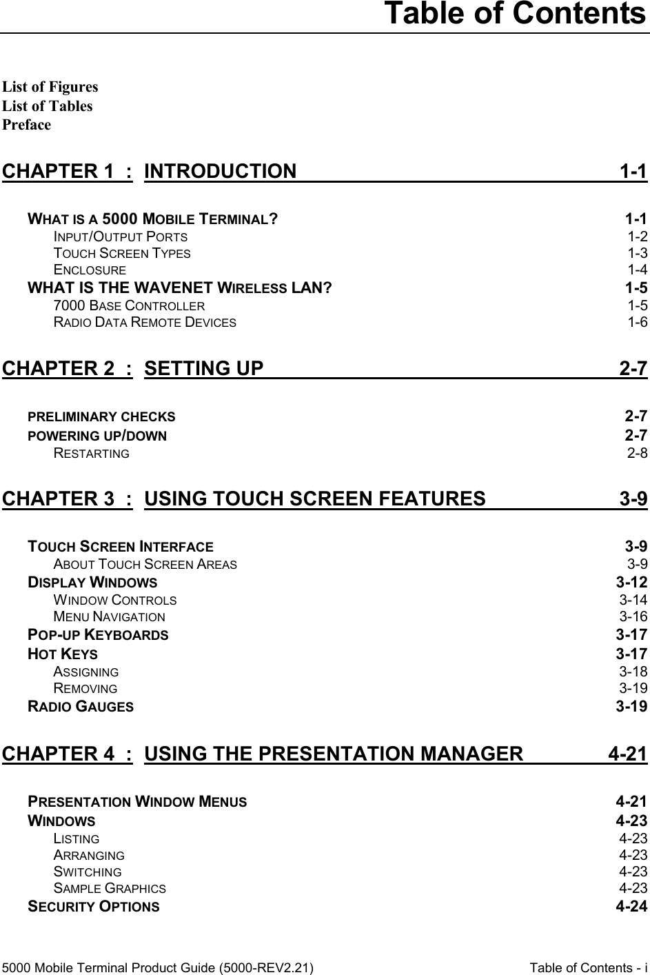
![Using the Session Manager 5000 Mobile Terminal Product Guide (5000-REV2.21) Chapter 6-58 The second is the Host Time Out configuration. This controls how long the terminal will try when attempting to establish an Auto-Connect before moving to the next Auto-Connect in the Auto-Connect list. The following example shows the Host Time Out configuration: >tel time tel>No Host response timeout >tel time 10 tel>Host response timeout: 10 seconds >tel time 0 tel>No Host response timeout ? Remember to save your Host Time Out configuration after you make changes! TELNET Auto-Login Services After an Auto-Connection is made to a host computer, usually the host computer requires the operator to supply a username and password. This security step can be bypassed at the host computer with an appropriate login script, or the 5000 Mobile Terminal can be configured to automatically supply the desired user name and password using the Auto-Login facility. Help facilities for Auto-Login configuration are available with the following command: >tel alog tel>on or en*able: Enable auto-logging tel>off or dis*able: Disable auto-logging tel>add or new: Create auto-login tel>del*ete or cl*ear: Delete auto-login: # tel>list or show: List auto-logins tel>move: Move auto-login: from to tel>for: Define range: [Node1] [NodeN] [Name] tel>host or IP: Set host address (0==all): IP# tel>max*user or use: Set maximum usage (0==all): # tel>name or user: Define username: prompt reply tel>pass*word: Define password: prompt reply tel>pr*ompt: Define host prompt: prompt [timer (ticks)] To use Auto-Login, the first step is to enable Auto-Logins: >tel alog on tel>Auto-logins enabled Second, define the host IP number that the Auto-Login will be assigned to: >tel alog add host 192.168.0.99 tel>Auto-login: IP: 192.168.0.99 Nodes: Any tel>User: Pass: Next, set the Username prompt text used by the host computer and the Username to be supplied: >tel alog name User: Wave tel>Auto-login: IP: 192.168.0.99 Nodes: Any](https://usermanual.wiki/WaveNet/WL7412-450.WaveNet-5000-Mobile-Terminal-Product-Guide/User-Guide-164956-Page-70.png)
![Using the Session Manager 5000 Mobile Terminal Product Guide (5000-REV2.21) Chapter 6-59 tel>User:[User:]=<Wave> Pass: >tel alog pass password: Net tel>Auto-login: IP: 192.168.0.99 Nodes: Any tel>User:[User:]=<Wave> Pass:[password:]=<Net> As with Auto-Connects, several host IP numbers with their respective Username/Password prompts and responses can be configured, as well as deleted: >tel alog add host 192.168.0.100 tel>Auto-login: IP: 192.168.0.100 Nodes: Any tel>User: Pass: >tel alog name username: 3000 tel>Auto-login: IP: 192.168.0.100 Nodes: Any tel>User:[username:]=<3000> Pass: >tel alog pass passwrd: PT tel>Auto-login: IP: 192.168.0.100 Nodes: Any tel>User:[username:]=<3000> Pass:[passwrd:]=<PT> > >tel alog list tel>Auto-logins are enabled tel>1) Auto-login: IP: 192.168.0.99 Nodes: Any tel>User:[User:]=<Wave> Pass:[password:]=<Net> tel>2) Auto-login: IP: 192.168.0.100 Nodes: Any tel>User:[username:]=<3000> Pass:[passwrd:]=<PT> > >tel alog del 1 tel>Deleting 1)Auto-login: IP: 192.168.0.99 Nodes: Any tel>User:[User:]=<Wave> Pass:[password:]=<Net> > >tel alog list tel>Auto-logins are enabled tel>1) Auto-login: IP: 192.168.0.100 Nodes: Any tel>User:[username:]=<3000> Pass:[passwrd:]=<PT> > >tel param save tel>Telnet parameters saved ? Note that when deleting Auto-Logins the list is renumbered with remaining Auto-Connects numbered from 1. ? Remember to save your Auto-Login list after you make changes! Terminal TELNET Server In order to facilitate monitoring and re-configuration of the terminal while operating in the 2.4 GHz (Aironet) radio system, a TELNET server can be enabled in the terminal. To configure this TELNET server, enter the following commands at the Console Session, or using the external Console connector: >tel listen for TCON tel>Listen port: IP: Any At: 23 Nodes: Any Name: <TCON> >tel param save](https://usermanual.wiki/WaveNet/WL7412-450.WaveNet-5000-Mobile-Terminal-Product-Guide/User-Guide-164956-Page-71.png)
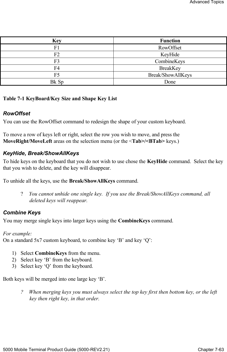

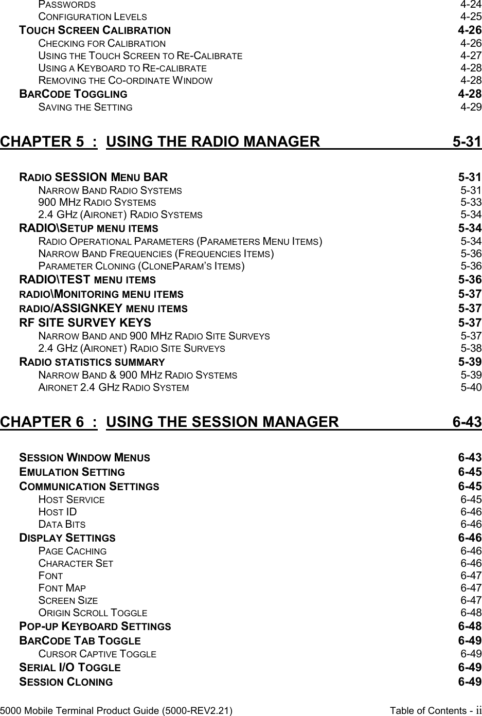
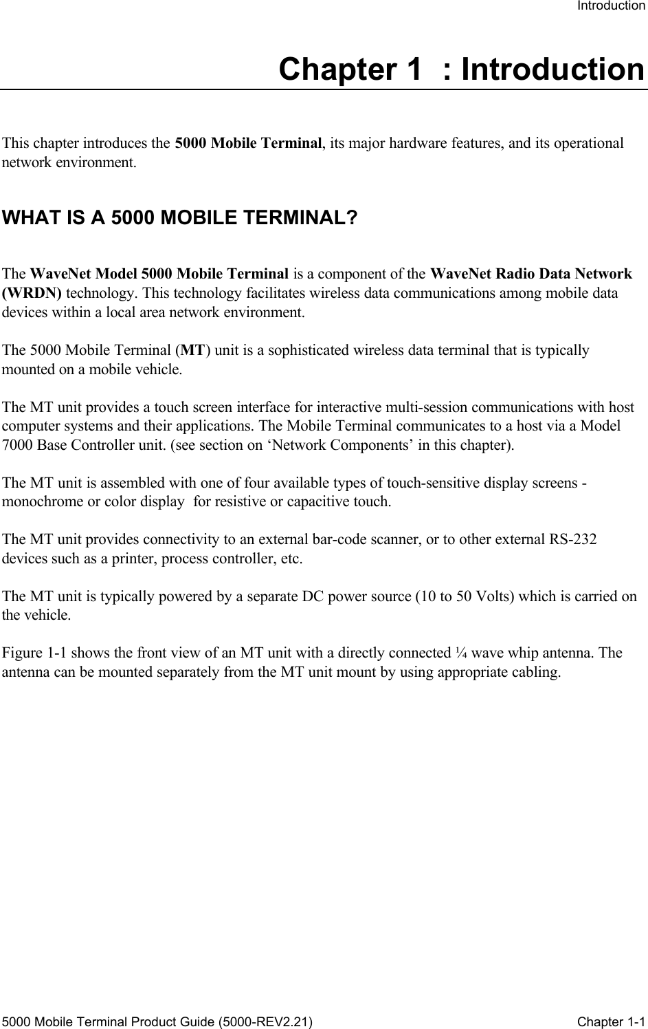
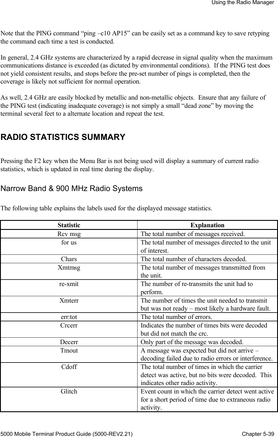
![Advanced Topics 5000 Mobile Terminal Product Guide (5000-REV2.21) Chapter 7-69 DOWNLOADING IMAGES TO FLASH MEMORY Flash memory tasks can be updated by downloading new image files. These files can be downloaded by using load task commands. ? Using load task commands requires access to the Command Line Interface via a Console device (see previous section), not via the touch Console window. The Console device has access to the new task images, whereas the Console window does not. An image file can be downloaded to one of four possible places in Flash memory: ?? At the start sector of an erased Flash memory. ?? At the next available space starting from low address. ?? At the highest available sector that can hold the image. ?? At a specific address. The Flash memory is protected against being modified while it is in use. If you attempt to download an image file to the Flash memory while the Flash memory is in use, the load task command will be rejected and an alert, “Flash in use!” will be displayed. To ensure that the Flash memory is not in use, use the command: >load flash now To restart the MT unit. Loading the Complete Flash Image In order to download a complete Flash image (set of tasks), there must be enough free low Flash memory available. High Flash memory is typically reserved for special tasks such as those involving character sets. To monitor and erase the current low Flash memory, use the commands: >load flash now To restart the MT unit. >load fp To obtain the first sector address. >FLSH e[first sector address] To erase contiguous memory beginning at [first sector address]. ? Do not use FLSH E command (with upper case E). This command will erase the high Flash memory in addition to the low Flash memory. Use the load fp command again to confirm that enough free memory is available. To download and activate the complete Flash image, use the commands: >load lf [filename] To load Flash image with [filename]. >load fir To install and run the Flash image in RAM. Loading a Task Image at Next Available Space](https://usermanual.wiki/WaveNet/WL7412-450.WaveNet-5000-Mobile-Terminal-Product-Guide/User-Guide-164956-Page-81.png)
![Advanced Topics 5000 Mobile Terminal Product Guide (5000-REV2.21) Chapter 7-70 This command is primarily used to add a new task . This may be required to add new features to the system or to provide a custom option. The load task installs images on sector boundaries. When a new image is downloaded, the first taskname in the image is checked against the first taskname of all images currently in the Flash memory. If the two names match, then the old image is overwritten. Otherwise, the new image is written starting at the first available new sector boundary. To load a task image at the next available space starting from low address, use the command: >load flash now To restart the MT unit. >load lf [filename] To load task image with [filename]. Installing a Task Image into High Memory High memory is an area in Flash memory which is unaffected by a new (complete) Flash image install procedure. It is generally reserved for character sets or custom tasks. To install a task image at the highest available sector that can hold the image, use the commands: >load flash now To restart the MT unit. >load lfh [filename] To load task image with [filename] into high memory. Installing a Task Image at Specific Address To install a task image at a specific start address, use the commands: >load flash now To restart the MT unit. >load lf@[address] [filename] To load task image with [filename] at [address]. If the [address] location already contains a task image, the task image with [filename] will be installed at the subsequent available sector.](https://usermanual.wiki/WaveNet/WL7412-450.WaveNet-5000-Mobile-Terminal-Product-Guide/User-Guide-164956-Page-82.png)
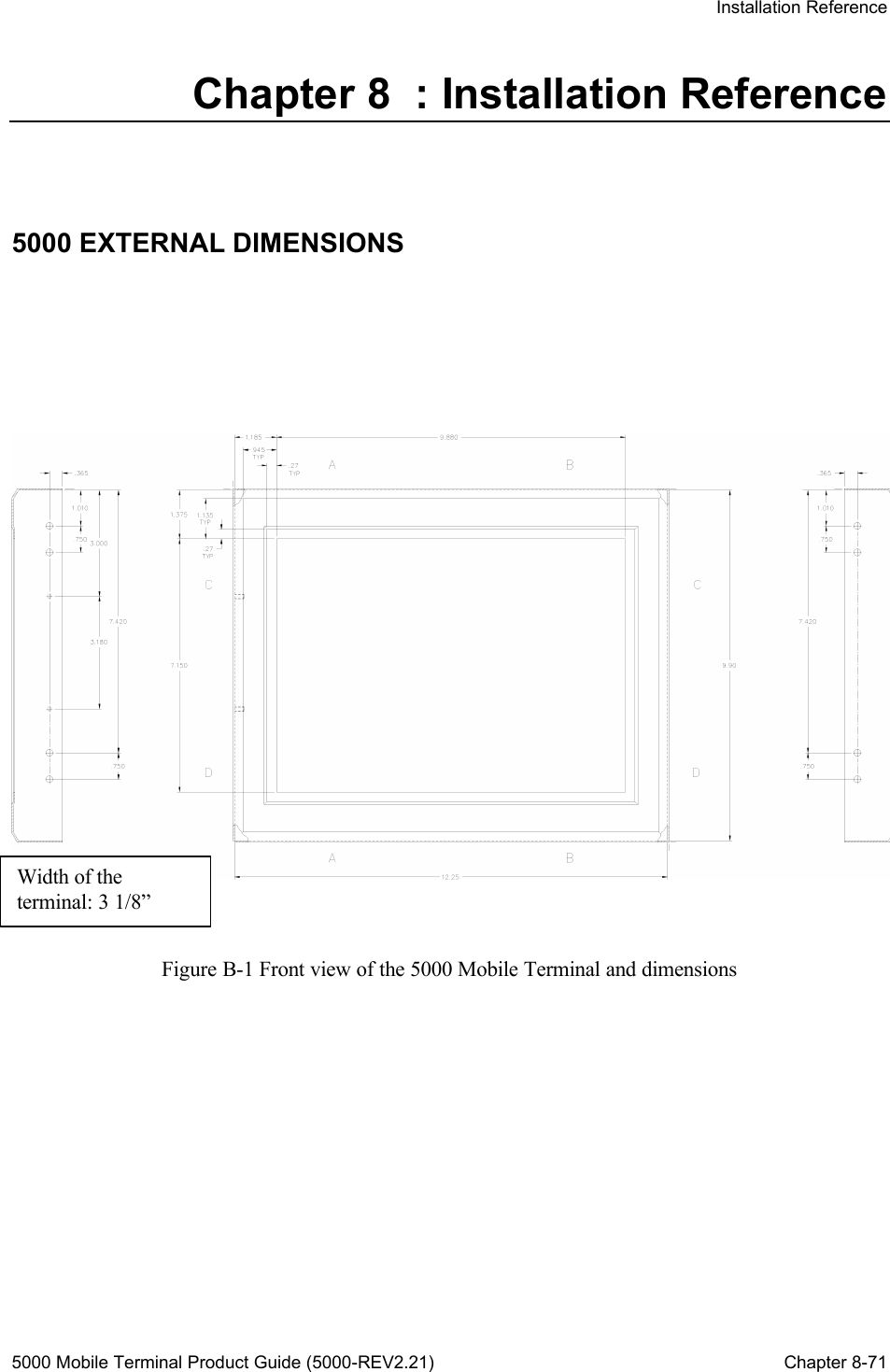
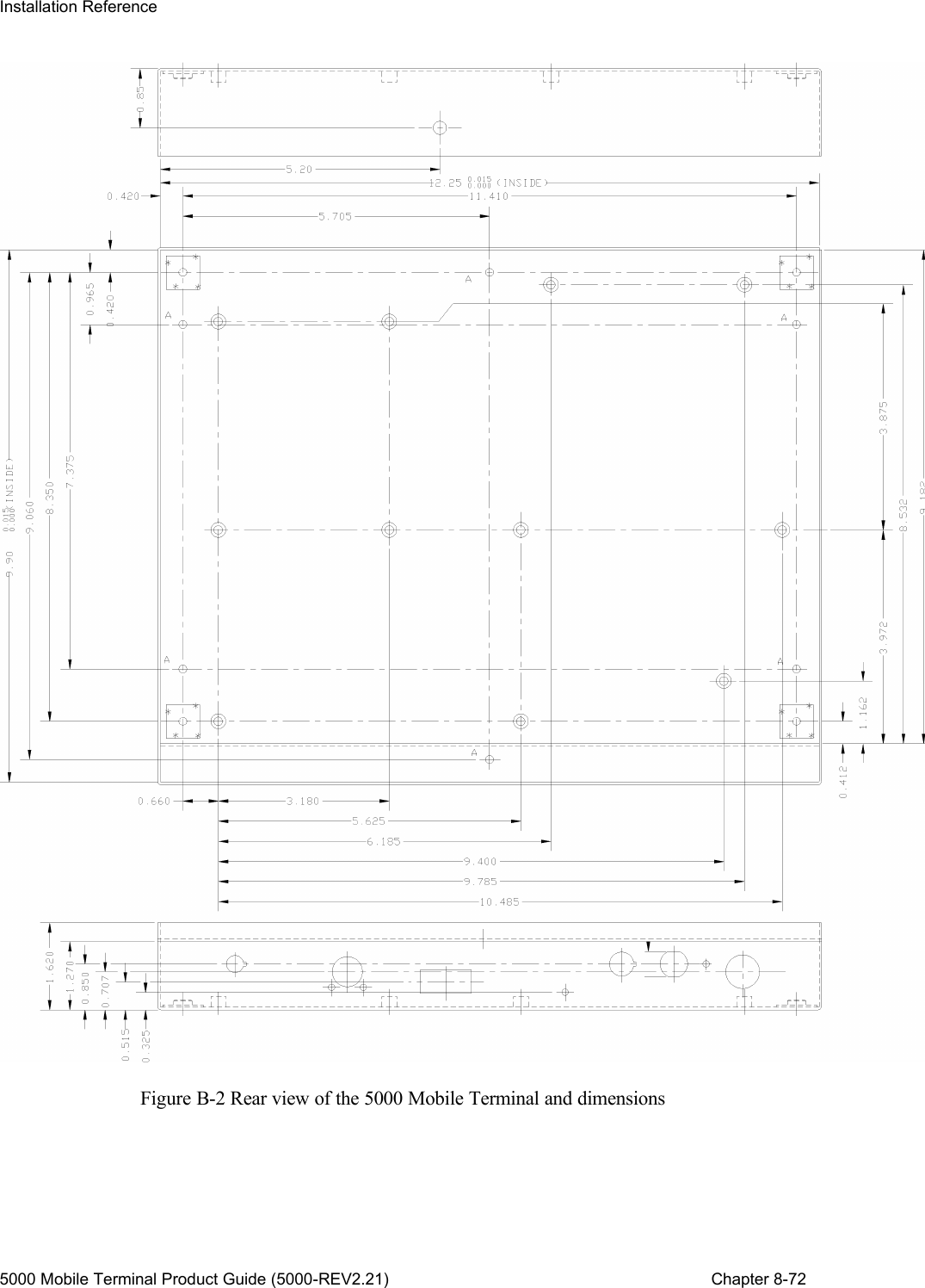
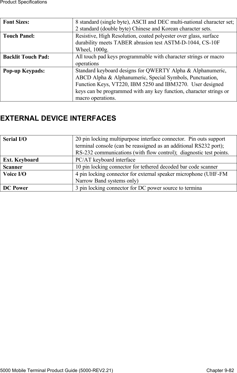
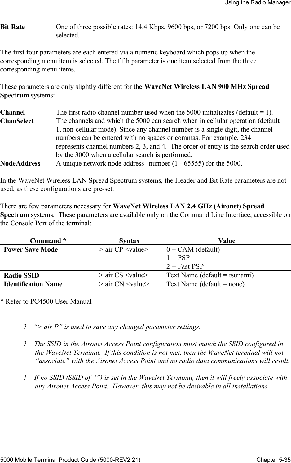
![Product Specifications 5000 Mobile Terminal Product Guide (5000-REV2.21) Chapter 9-81 Chapter 9 : Product Specifications Note : Product specifications subject to change. PHYSICAL & ENVIRONMENTAL Enclosure: Sealed NEMA style steel with poly-enamel finish. Size & Weight: 12.4 (W) x 10.0 (H) x 3.1 (D) in. [31.2 x 25.2 x 7.8 cm], 10.1 lbs. [4.6 Kg.]. Shock & Vibration: Rated to MIL-STD 810D. Power: 12 - 60 VDC @ < 3.0 Amp, Surge protection & filtering inc., AC power Optional with external convertor. Operating Environment: 0 to 50ºC (14 to 122ºF), Optional -30ºC to 50ºC (-22 to 122ºF) with optional internal heater. Meets 4 inch per hour ambient rain. Storage Temperature: -30 to 60ºC (-22 to 122ºF) Relative Humidity: 5 to 95 % (Non-Condensing) ARCHITECTURE Processor: Integrated 32-Bit CISC General Purpose Processor with dedicated RISC Communications Processor; 8-bit auxiliary microcontroller. FLASH Memory: 2 MByte (maximum) RAM: 768 KByte (maximum) EEPROM: 2 KByte RADIO TECHNOLOGIES Narrow Band UHF-FM: 406-512 MHz, 8-Channel Synthesized, 0.1 - 2.0 Watts, 14,400 bps maximum channel speed. Spread Spectrum: 902-928 MHz, 7-Channel Synthesized, 122 Kbps maximum channel speed, direct sequence. 2.4 GHz Aironet 4500/4800 (1& 2 Mbps) 802.11 compliant DISPLAY/KEYBOARD Display: Color - 16 colors, 10.4 in. (26.4cm) diagonal, 25 lines by 80 characters, backlit. Mono - 16 grayscale, 10.4 in. (26.4 cm) diagonal, 25 lines by 80 characters, backlit.](https://usermanual.wiki/WaveNet/WL7412-450.WaveNet-5000-Mobile-Terminal-Product-Guide/User-Guide-164956-Page-93.png)