WaveNet WL7412-450 Transceiver Module User Manual 5000 Product Guide R2 22
WaveNet International Inc Transceiver Module 5000 Product Guide R2 22
WaveNet >
Contents
- 1. E F Johnson Company High Specification Data Transceiver
- 2. WaveNet 5000 Mobile Terminal Product Guide
WaveNet 5000 Mobile Terminal Product Guide

5000 MOBILE TERMINAL
PRODUCT GUIDE
Version 2.22

WaveNet International Inc. Telephone : 1 905 712 4700
5825 Kennedy Road Facsimile : 1 905 712-4703
Mississauga, Ontario Email : wavenet@wavenet-rf.com
Canada L4Z 2G3
© 1997 WaveNet International Inc. All rights reserved.
WaveNet International Inc. reserves the right to amend the contents of this guide at any time to reflect product
development and product improvements.
Regulations and Approvals
The 5000 Mobile Terminal (MT) equipment has been designed to comply with international standards for product safety,
electromagnetic compatibility, and radio transceiver operation. These standards can vary by the country of use, frequency
of operation, and modulation technique. At the time of writing, the 5000 MT has been certified to the applicable standards
for the US, Canadian and UK markets.
In the United States, the 5000 MT complies with UL/CSA requirements for safety, and the radio transceivers are type
approved to the following standards:
FCC Parts 2 and 90 (for 450 to 470 MHz narrow band operation),
FCC Part 15 (for 902 to 928 MHz direct sequence spread spectrum operation).
This equipment has been tested and found to comply with the limits for Class A digital devices, pursuant to Part 15 of the
FCC rules. These limits are designed to provide reasonable protection against harmful interference when the equipment is
operated in a commercial environment. The equipment generates, uses, and can radiate radio frequency energy and, if not
installed and used in accordance with the instruction manual, may cause harmful interference to radio communications.
Operation of this equipment in a residential area will cause harmful interference, in which case the user will be required
to correct the interference at the user’s own expense. All external cables must be shielded to ensure compliance with the
Class A FCC limits.
In situations where the user elects to install WaveNet specified equipment including high gain antenna kits, the user will
be responsible for adhering to all pertinent FCC, fire and safety/building code regulations pertaining to the installation.
WARNING: Changes or modifications to the equipment, not expressly approved by WaveNet International Inc.
could void the user’s authority to operate the equipment and void the warranty.
In the UK, the 5000 MT carries the CE mark. Radio transceivers of the 5000 MT are type approved to the following ETS
standards:
ETS 300 220 (for 450 to 466 MHz operation),
ETS 300 086/113 (for 450 to 466 MHz operation).
For more information on 5000 MT regulatory approvals, contact your local WaveNet representative.
RF EXPOSURE WARNING
In order to ensure user safety and to satisfy RF exposure requirements for mobile transmitting devices, a minimum
separation distance of 25 cm. (10 inches) must be maintained between the transmitting device and the user (or other
nearby persons) during device operation. Operation at smaller separation distances is not recommended.

5000 Mobile Terminal Product Guide (5000-REV2.21) Table of Contents - i
Table of Contents
List of Figures
List of Tables
Preface
CHAPTER 1 : INTRODUCTION 1-1
WHAT IS A 5000 MOBILE TERMINAL? 1-1
INPUT/OUTPUT PORTS 1-2
TOUCH SCREEN TYPES 1-3
ENCLOSURE 1-4
WHAT IS THE WAVENET WIRELESS LAN? 1-5
7000 BASE CONTROLLER 1-5
RADIO DATA REMOTE DEVICES 1-6
CHAPTER 2 : SETTING UP 2-7
PRELIMINARY CHECKS 2-7
POWERING UP/DOWN 2-7
RESTARTING 2-8
CHAPTER 3 : USING TOUCH SCREEN FEATURES 3-9
TOUCH SCREEN INTERFACE 3-9
ABOUT TOUCH SCREEN AREAS 3-9
DISPLAY WINDOWS 3-12
WINDOW CONTROLS 3-14
MENU NAVIGATION 3-16
POP-UP KEYBOARDS 3-17
HOT KEYS 3-17
ASSIGNING 3-18
REMOVING 3-19
RADIO GAUGES 3-19
CHAPTER 4 : USING THE PRESENTATION MANAGER 4-21
PRESENTATION WINDOW MENUS 4-21
WINDOWS 4-23
LISTING 4-23
ARRANGING 4-23
SWITCHING 4-23
SAMPLE GRAPHICS 4-23
SECURITY OPTIONS 4-24

5000 Mobile Terminal Product Guide (5000-REV2.21) Table of Contents - ii
PASSWORDS 4-24
CONFIGURATION LEVELS 4-25
TOUCH SCREEN CALIBRATION 4-26
CHECKING FOR CALIBRATION 4-26
USING THE TOUCH SCREEN TO RE-CALIBRATE 4-27
USING A KEYBOARD TO RE-CALIBRATE 4-28
REMOVING THE CO-ORDINATE WINDOW 4-28
BARCODE TOGGLING 4-28
SAVING THE SETTING 4-29
CHAPTER 5 : USING THE RADIO MANAGER 5-31
RADIO SESSION MENU BAR 5-31
NARROW BAND RADIO SYSTEMS 5-31
900 MHZ RADIO SYSTEMS 5-33
2.4 GHZ (AIRONET) RADIO SYSTEMS 5-34
RADIO\SETUP MENU ITEMS 5-34
RADIO OPERATIONAL PARAMETERS (PARAMETERS MENU ITEMS) 5-34
NARROW BAND FREQUENCIES (FREQUENCIES ITEMS) 5-36
PARAMETER CLONING (CLONEPARAM’S ITEMS) 5-36
RADIO\TEST MENU ITEMS 5-36
RADIO\MONITORING MENU ITEMS 5-37
RADIO/ASSIGNKEY MENU ITEMS 5-37
RF SITE SURVEY KEYS 5-37
NARROW BAND AND 900 MHZ RADIO SITE SURVEYS 5-37
2.4 GHZ (AIRONET) RADIO SITE SURVEYS 5-38
RADIO STATISTICS SUMMARY 5-39
NARROW BAND & 900 MHZ RADIO SYSTEMS 5-39
AIRONET 2.4 GHZ RADIO SYSTEM 5-40
CHAPTER 6 : USING THE SESSION MANAGER 6-43
SESSION WINDOW MENUS 6-43
EMULATION SETTING 6-45
COMMUNICATION SETTINGS 6-45
HOST SERVICE 6-45
HOST ID 6-46
DATA BITS 6-46
DISPLAY SETTINGS 6-46
PAGE CACHING 6-46
CHARACTER SET 6-46
FONT 6-47
FONT MAP 6-47
SCREEN SIZE 6-47
ORIGIN SCROLL TOGGLE 6-48
POP-UP KEYBOARD SETTINGS 6-48
BARCODE TAB TOGGLE 6-49
CURSOR CAPTIVE TOGGLE 6-49
SERIAL I/O TOGGLE 6-49
SESSION CLONING 6-49

5000 Mobile Terminal Product Guide (5000-REV2.21) Table of Contents - iii
CLONING A SESSION WINDOW 6-50
DELETING A CLONED SESSION WINDOW 6-50
ABOUT THE CURRENT SESSION 6-50
ON-LINE DEMONSTRATION SESSION (“DEMO” SERVICE) 6-51
CONFIGURATION 6-51
NAVIGATING THE DEMO SESSION 6-52
LOCAL CONSOLE SESSION 6-54
2.4 GHZ LOCAL TELNET SESSIONS 6-54
SETTING THE TERMINAL IP NUMBER 6-55
USING DNS SERVICES 6-55
TELNET AUTO-CONNECTIONS 6-56
TELNET AUTO-LOGIN SERVICES 6-58
TERMINAL TELNET SERVER 6-59
CHAPTER 7 : ADVANCED TOPICS 7-61
HOST COLOR/TOUCH OPTIONS 7-61
DESIGNING A CUSTOM KEYBOARD 7-61
KEYBOARD CUSTOMIZATION 7-62
CHANGING THE KEYBOARD/KEY SIZE AND SHAPE 7-62
ASSIGNING KEY FEATURES 7-64
KEY FONTS 7-64
ENTERING KEY TEXT 7-65
ENTERING KEY DATA 7-65
SAVING CUSTOM KEYBOARDS 7-65
DELETING A CUSTOM KEYBOARD 7-66
ASSIGNING HOT KEYS TO KEYBOARDS 7-66
REVIEWING KEYBOARDS 7-66
USING A PC KEYBOARD 7-66
USING THE TOUCH CONSOLE WINDOW 7-67
CONNECTING A CONSOLE DEVICE 7-68
DOWNLOADING IMAGES TO FLASH MEMORY 7-69
CHAPTER 8 : INSTALLATION REFERENCE 8-71
5000 EXTERNAL DIMENSIONS 8-71
UNIVERSAL TRUCK MOUNTING BRACKET DIMENSIONS 8-73
MODEL 5000 MOBILE TERMINAL JUMPER CONFIGURATIONS 8-75
SRAM (J2) 8-75
WATCH DOG TIMER (J3) 8-75
REMOTE HEATER PANEL (J4/J11) 8-75
SRAM TEST (J21) 8-75
EEPROM (J23) 8-75
SCANNER CONNECTOR 8-76
SCANNER CONNECTOR SIGNALS 8-76
SYMBOL DECODING SCANNER INTERFACE (TYPICAL) 8-76
CONSOLE/SERIAL I/O CONNECTOR 8-77
TYPICAL EXTERNAL CONSOLE & DEVICE CABLE CONNECTIONS 8-77
POWER CONNECTOR AND EXTENSION CABLE 8-78

5000 Mobile Terminal Product Guide (5000-REV2.21) Table of Contents - iv
SPEAKER/MIC PORT 8-79
CHAPTER 9 : PRODUCT SPECIFICATIONS 9-81
PHYSICAL & ENVIRONMENTAL 9-81
ARCHITECTURE 9-81
RADIO TECHNOLOGIES 9-81
DISPLAY/KEYBOARD 9-81
EXTERNAL DEVICE INTERFACES 9-82
CHAPTER 10 : REVISION HISTORY 9-83
INDEX 84

5000 Mobile Terminal Product Guide (5000-REV2.21) List of Figures - i
List of Figures
FIGURE 1-1 FRONT VIEW OF THE 5000 MOBILE TERMINAL 1-2
FIGURE 1-2 BOTTOM VIEW OF THE 5000 MOBILE TERMINAL 1-2
FIGURE 1-3 A MOUNTED 5000 MOBILE TERMINAL 1-5
FIGURE 3-1 TOUCH SCREEN AREAS 3-10
FIGURE 3-2 THE DISPLAY AREA 3-11
FIGURE 3-3 THE TOUCH KEYPAD OVERLAY 3-12
FIGURE 3-4 EXAMPLE MULTIPLE WINDOWS 3-13
FIGURE 3-5 THE WINDOW CONTROLS 3-15
FIGURE 3-6 RADIO GAUGES 3-19
FIGURE 4-1 OFFSET CURSOR 4-27
FIGURE 4-2 TOUCHING THE UR CORNER 4-28
FIGURE 7-1 THE CONSOLE SETUP 7-68

5000 Mobile Terminal Product Guide (5000-REV2.21) List of Tables - i
List of Tables
TABLE 4-1 PRESENTATION WINDOW MENU MAP 4-22
TABLE 6-1 THE SESSION MANAGER WINDOW MENU STRUCTURE 6-45
TABLE 6-2 FONT AND SCREEN SIZES 6-48
TABLE 7-1 KEYBOARD/KEY SIZE AND SHAPE KEY LIST 7-63
TABLE 7-2 KEY FEATURE LIST 7-64

Preface
5000 Mobile Terminal Product Guide (5000-REV2.21) Preface - 1
Preface
This user guide is intended for use by technical support personnel who require information to operate,
configure or maintain a WaveNet Model 5000 Mobile Terminal unit. This unit is a data terminal
component of the WaveNet Radio Data Network (WRDN) technology. This unit supports wireless data
communications. The wireless medium used by the WRDN is the radio frequency signal.
This guide assumes that the 5000 Mobile Terminal is, at least, a minimally configured unit as supplied
by WaveNet.
How to Use this Guide
This guide is organized into seven chapters, a glossary and an index. The following chapter
descriptions indicate the scope of this guide:
Chapter 1 Introduces the 5000 Mobile Terminal, its major hardware features, and its
operational network environment.
Chapter 2 Discusses how to set up the 5000 Mobile Terminal to prepare for
configuration, monitoring, and advanced operations.
Chapter 3 Discusses how to utilize the major touch screen features of the 5000 Mobile
Terminal.
Chapter 4 Explains how to utilize the Presentation Manager window menu functions of
the 5000 Mobile Terminal.
Chapter 5 Explains how to utilize the Radio Manager window menu functions of the
5000 Mobile Terminal.
Chapter 6 Explains how to utilize the Session Manager window menu functions of the
5000 Mobile Terminal.
Chapter 7 Explains how to utilize current advanced procedures for maintaining or
upgrading the 5000 Mobile Terminal.
In general, labeled keys and menu items are depicted in bold type and with similar character case. In
addition, the labeled keys are shown within angle brackets. For example:
?? the <ENTER> key.
?? the KB Assign menu item.
Comments to be noted are highlighted with: ?

Introduction
5000 Mobile Terminal Product Guide (5000-REV2.21) Chapter 1-1
Chapter 1 : Introduction
This chapter introduces the 5000 Mobile Terminal, its major hardware features, and its operational
network environment.
WHAT IS A 5000 MOBILE TERMINAL?
The WaveNet Model 5000 Mobile Terminal is a component of the WaveNet Radio Data Network
(WRDN) technology. This technology facilitates wireless data communications among mobile data
devices within a local area network environment.
The 5000 Mobile Terminal (MT) unit is a sophisticated wireless data terminal that is typically
mounted on a mobile vehicle.
The MT unit provides a touch screen interface for interactive multi-session communications with host
computer systems and their applications. The Mobile Terminal communicates to a host via a Model
7000 Base Controller unit. (see section on ‘Network Components’ in this chapter).
The MT unit is assembled with one of four available types of touch-sensitive display screens -
monochrome or color display for resistive or capacitive touch.
The MT unit provides connectivity to an external bar-code scanner, or to other external RS-232
devices such as a printer, process controller, etc.
The MT unit is typically powered by a separate DC power source (10 to 50 Volts) which is carried on
the vehicle.
Figure 1-1 shows the front view of an MT unit with a directly connected ¼ wave whip antenna. The
antenna can be mounted separately from the MT unit mount by using appropriate cabling.
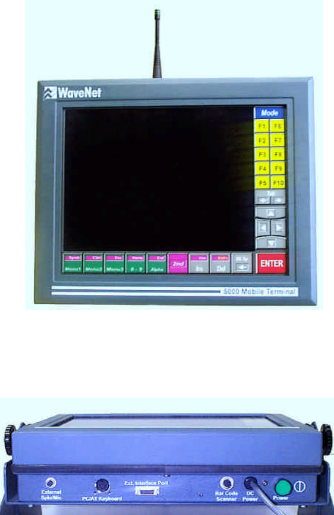
Introduction
5000 Mobile Terminal Product Guide (5000-REV2.21) Chapter 1-2
Figure 1-1 Front View of the 5000 Mobile Terminal
Figure 1-2 shows the bottom view of an MT unit where various connectors, a power ON/OFF push-
button switch, and a DC power cable are located.
Figure 1-2 Bottom View of the 5000 Mobile Terminal
Input/Output Ports
The MT unit provides one RF port at the antenna connector (see Figure 1-1). The unit also provides
one Console port (for servicing the unit), a bar-code scanner port, a keyboard port, and a voice port at
the bottom of the unit (see Figure 1-2).
Introduction
5000 Mobile Terminal Product Guide (5000-REV2.21) Chapter 1-3
RF Port
This port uses an RF connector, type SMA bulkhead jack, to connect a radio antenna that matches the
installed radio technology transceiver. A wave whip antenna can be directly attached at the connector
or, indirectly, via a length of RG-58/U 50 Ohm coaxial cable (usually attached to a magnetic mount for
the antenna). The coaxial connectors are typically ‘reverse threaded’ to prevent an inappropriate
antenna from being inadvertently attached.
Console Port
The console (external interface) port (20 pins) provides a servicing interface for the configuring,
testing, monitoring, and reporting functions that can be applied to the MT unit. This port supports full
RS-232 modem functionality for remote servicing.
? This port is disabled when the Scanner Port is enabled.
Scanner Port
The scanner port is RS-232 compatible, and is mainly used to attach a bar-code laser scanner. This
port can also be used for other serial input/output applications. This port is enabled via the BarCode
menu item of the Presentation Manager’s Local menu.
Keyboard Port
The keyboard port is used to attach an external PC compatible keyboard to serve as an alternative to
the touch screen pop-up keyboards.
? The <Alt> key on a connected external keyboard is equivalent to the touch -screen’s
<2nd> key.
Voice Port
The voice port is used to attach a speaker/microphone unit for voice communications with other MT
units, which are similarly configured. Voice communication is via point-to-point analog radio signal.
The voice radio channel is enabled/disabled via the Voice menu item of the Presentation’s Manager’s
Global menu.
? Note that when the voice channel is active, the data channel is inactive.
Touch Screen Types
The MT unit is assembled with one of four available types of touch-sensitive display screens -
monochrome or color display for resistive or capacitive touch. The display screen is a liquid crystal
display (LCD) with diffused Cold Cathode Florescent Tube (CCFT) back lighting. Covering the
screen, is a transparent touch-sensitive layer.
The touch screen size is 12.2 inches diagonal (1024 x 1024 pixels). Within the screen area, is a 10.4
inches diagonal display area (640 x 480 pixels) which can be either VGA color (16 colors) or VGA
Introduction
5000 Mobile Terminal Product Guide (5000-REV2.21) Chapter 1-4
monochromatic (16 gray levels). Bordering the display area, is a dedicated colored keypad overlay. See
Figure 1-1.
Color displays offer more distinctive details than that of monochrome displays; whereas, monochrome
displays are more visible in direct sunlight than the color displays are.
Capacitive type touch-screens operate based on skin contact on a surface contact layer (contact alters
the local electrical capacitance to identify a cursor location). Dirty skin or screen surface, or excessive
moisture is detrimental to the touch capability.
Resistive type touch screens operate based on surface contact pressure (two separated transparent
conductive layers are pressed together at the contact point to identify a cursor location). These screens
can be operated via skin contact, or with gloved fingers or pointed objects. Operation of resistive
screens are tolerant of some surface grime.
? The touch screen should not be touched for at least five seconds after the display
becomes visible after powering up, in order to allow the screen hardware to initialize
properly.
The touch screen should be kept clean (use a mild cleaning agent) and away from corrosive materials,
to ensure viewing clarity and dependable operation. The touch screen assembly does have a gasket
sealing the enclosure to prevent any moisture from entering and affecting any circuitry.
Enclosure
The MT unit is packaged in a dust and water-resistant enclosure with a poly-enamel finish. See Figure
1-1 for a front view of the enclosure.
The MT unit operates within a -10 to +40 degree Celsius temperature range and within a 5 to 95 %
relative humidity range.
The MT unit can be mounted directly to a frame, which is in turn connected via two horizontal pivot
pins to a cradle that is attached to the mobile vehicle. This assembly would provide tilt adjustment for
optimizing the viewing angle of the MT display screen. The assembly must be capable of supporting
the weight of the MT unit during shocks and vibrations incurred by the mobile vehicle.
The enclosure occupies a space 12.4 inches wide, 10.1 inches high, and 3.4 inches deep.
The following figure shows a MT unit attached to a pivot-type mount assembly.
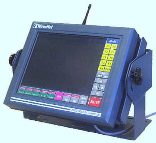
Introduction
5000 Mobile Terminal Product Guide (5000-REV2.21) Chapter 1-5
Figure 1-3 A Mounted 5000 Mobile Terminal
WHAT IS THE WAVENET WIRELESS LAN?
The WaveNet Wireless LAN is a local area radio data network designed for scaleable, digital radio
data communications, which allows a variety of computer systems to communicate, interactively or
periodically, to a number of remote, mobile data devices.
A WaveNet Radio Data Network consists of a one or more 7000 Base Controllers, and combination of
WaveNet Radio Data Remote Devices.
7000 Base Controller
7000 Base Controllers connect to computer systems and provide zones of radio data coverage in
which Radio Data Remote Devices can utilize for radio data communications.
7000 Base Controllers can establish a network of overlapping or discrete radio data coverage zones if
they are interconnected by any combination of Ethernet LAN, serial SLIP, or wireless radio data links.
In such a network, any host computer system connected to any 7000 Base Controller is available to any
Radio Data Remote Device in any radio data coverage area as a 7000 Base Controller “service”.
Introduction
5000 Mobile Terminal Product Guide (5000-REV2.21) Chapter 1-6
Radio Data Remote Devices
Radio Data Remote Devices, when in the coverage zones of one or more 7000 Base Controllers,
utilize the radio data communications pathway to the various host computer systems connected to the
7000 Base Controllers. In such a manner, the Radio Data Remote Devices can :
?? Interact in real-time with software applications on one or more host computer systems as a
“dumb” terminal of the computer system extension (using a process called “emulation”);
and/or,
?? Periodically exchange text based data records with the computer system using a local program
in the Radio Data Remote Device.
Radio Data Remote Devices provided by WaveNet are :
Model 5000 Mobile Terminal - utilizes a full 24x80 LCD screen and integrated touch-screen
interface, housed in a full metal enclosure, for multi-windowed interactive multi-session
communications. External bar code scanner and external RS-232 communications for printers,
process controllers, etc., are also supported. The 5000MT is designed for use within industrial
vehicles of all types, or stationary wired terminal replacement.
Model 3100 Portable AEI Terminal – an extension of the 3000 Portable Terminal,
incorporating an integral AAR/ISO compatible AEI Tag reader as well as an optional integral
bar code reader. The 3100 Portable AEI Terminal is also capable of operating without a radio
data link, and can exchange data with computer systems via RS-232 serial communications.
Model 3000 Portable Terminal - utilizes a full keypad and large LCD display, housed in a
small plastic enclosure, for interactive multi-session communications. External bar code
scanner and external RS-232 communications for printers, process controller, etc., are also
supported. The 3000 also has several optional selections such as internal or bar code readers,
a pistol grip, various holsters, battery technologies and charging systems. The 3000 is
designed for portable industrial applications of all types.
Model 1100 Network AEI Reader - provides remote, unattended reading of ISO and AAR
Tags with read reporting to computer systems via the WaveNet Radio Data Network or
without the WaveNet Radio Data Network via RS-232 serial links.
For more information regarding the WaveNet Radio Data Network, please refer to the publication
entitled “Introduction To WaveNet Systems”.

Setting Up
5000 Mobile Terminal Product Guide (5000-REV2.21) Chapter 2-7
Chapter 2 : Setting Up
This chapter discusses how to set up the 5000 Mobile Terminal to prepare for configuration,
monitoring, and advanced operations.
PRELIMINARY CHECKS
Before beginning any operation on the 5000 Mobile Terminal (MT) unit, the following items should be
checked:
?? Ensure that the MT enclosure is appropriately mounted. For vehicle mounting, it is
recommended that the MT display screen be positioned for optimal viewing angle. The MT
mounting assembly should be secure enough to withstand shocks and vibrations incurred by
vehicle motions. In addition, the power line cord should be secured against accidental removal
from the power source.
?? Ensure that the antenna is appropriately attached to the MT unit. The antenna may be directly
connected to the RF connector on the MT unit or remotely connected via a coaxial cable.
Ensure that every connection is ‘finger’ tight.
POWERING UP/DOWN
The MT unit accepts external DC power (10 - 50 Volts) via the DC power cable mounted on the
bottom of the enclosure (see Figure 1-2). DC power can be supplied from a properly fused DC source
or alternatively from an AC to DC converter.
? The MT unit should not be powered up without its antenna. Improper antenna port
termination causes impedance mismatches, which can reflect damaging levels of RF
power back to the transceiver.
Powering up the MT unit is accomplished by pressing the green push-button power ON/OFF switch.
The switch will release into the ON position and the switch indicator will turn on.
? When powering up the MT unit, do not touch the display for at least 5 seconds after the
display becomes visible. This allows the touch screen hardware to initialize properly.
Powering down the MT unit is accomplished by pressing the green push-button power ON/OFF
switch. The switch will latch into the OFF position and the switch indicator will turn off.
The MT unit provides RAM Backup for up to 48 hours. Thus, if the MT unit is powered down and
then powered up within the 48 hours, the most recent RAM memory entries will be restored.
Setting Up
5000 Mobile Terminal Product Guide (5000-REV2.21) Chapter 2-8
Restarting
The MT can be re-initialized via the touch screen by pressing the <2nd> key twice in rapid succession
followed by switching power OFF and then power ON in slower succession.
Upon restart, the terminal screen will be momentarily blurred while the operating system loads, the
terminal self-checks are performed, the hardware configurations are recognized, and the software start-
up sequence is initiated. The terminal will then display the Presentation Manager (P.M.) window and
the WaveNet logo. Touching any key on the overlay keypad will clear the logo and allow operation of
the terminal.
? Do not rapidly cycle the DC power ON/OFF switch; this could disrupt touch screen
operation.

Using Touch Screen Features
5000 Mobile Terminal Product Guide (5000-REV2.21) Chapter 3-9
Chapter 3 : Using Touch Screen Features
This chapter discusses how to utilize the major touch screen features of the 5000 Mobile Terminal
(MT) unit.
This chapter discusses:
?? Touch Screen Interface
?? Display Windows
?? Pop-up Keyboards
?? Hot Keys
?? Radio Gauges
TOUCH SCREEN INTERFACE
This section discusses the following basic interface features of the touch screen:
?? About Touch Screen Areas
?? About Touch Responses
See also, the section on Touch Screen Types in Chapter 1.
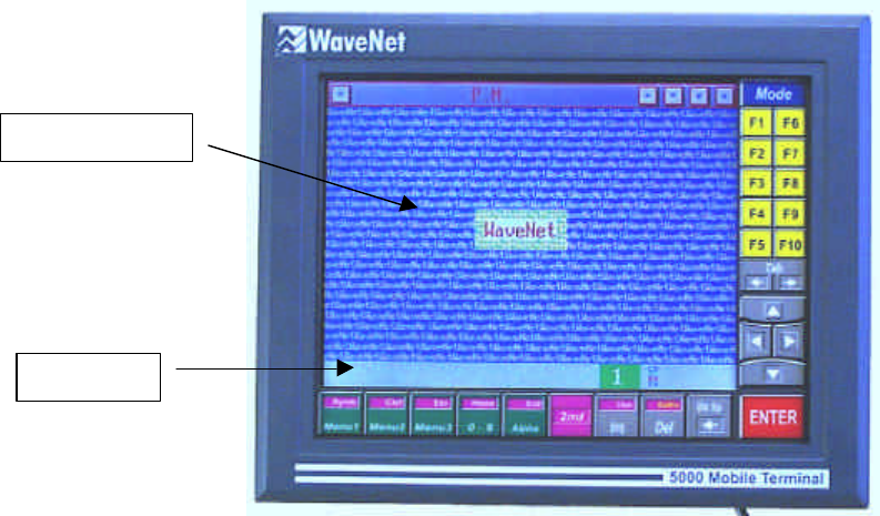
About Touch Screen Areas
The touch screen consists of two distinct areas; a display area bordered on two sides by a keypad
overlay.
The following figure identifies the two main touch screen areas. This example shows a blank display
area with the illustrated keypad overlay.
Using Touch Screen Features
5000 Mobile Terminal Product Guide (5000-REV2.21) Chapter 3-10
Figure 3-1 Touch Screen Areas
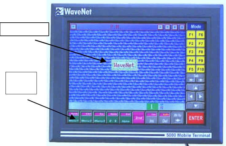
The Display Area
The display area supports a windows area and a status bar area.
The windows area is used to present:
?? Presentation Manager (P.M.) window
?? Radio Manager window
?? Session Manager windows
?? Various pop-up keyboards
?? Various pop-up dialog boxes
?? Console window
The status bar area is used to provide:
?? Selection indicators
?? Operator prompts
?? Session states
?? Radio gauges
The following figure identifies the main features of the display area. This figure shows a single
example blank window with default status bar indications.
Display Area
Keypad
Overlay
Using Touch Screen Features
5000 Mobile Terminal Product Guide (5000-REV2.21) Chapter 3-11
Figure 3-2 The Display Area
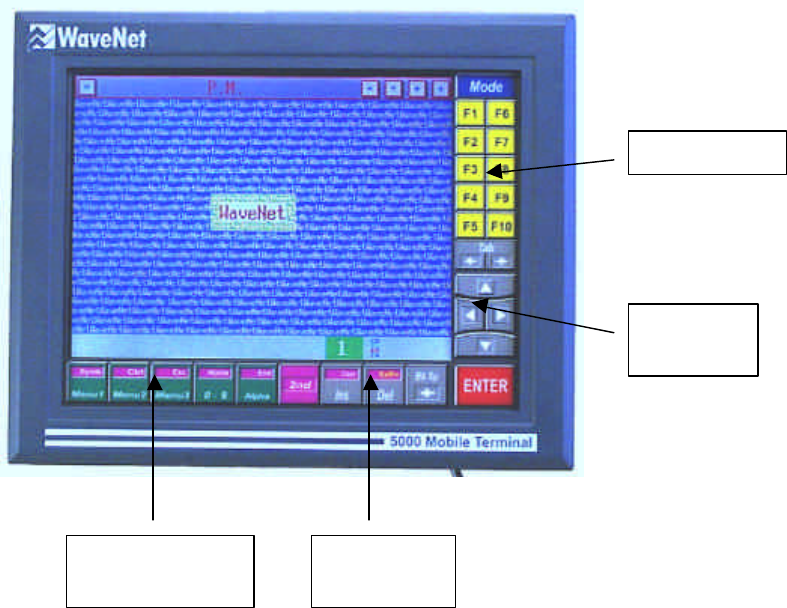
The Keypad Overlay
The keypad overlay supports various utility groups of touch-sensitive keys:
?? Navigation keys
?? Function keys
?? Pop-up keyboard toggles
?? Text editor keys
The following figure identifies the various groups of overlay touch keys.
Windows Area
Status Bar
Using Touch Screen Features
5000 Mobile Terminal Product Guide (5000-REV2.21) Chapter 3-12
Figure 3-3 The Touch Keypad Overlay
About Touch Responses
The touch screen area contains touch-sensitive and non-touch-sensitive areas. There are two types of
touch feedback; beep sound and graphic cursor.
In general, when you touch a window or the keypad overlay and then remove your contact, a beep
sound will occur to acknowledge that your touch has been recognized. There is no beep
acknowledgment when you touch a point on a non-window area within the display area.
Whenever you touch a touch-sensitive area, a cursor in the form of a cross will appear under the
contact point. Sliding the contact point across the display area will cause the touch cursor to track the
movement. When the touch contact is removed, the cursor will disappear.
The status bar is not touch-sensitive.
DISPLAY WINDOWS
Multiple display windows can appear on the touch screen at the same time. Each window has a
horizontal title bar along the top of the window. When a window is inactive, only the name of the
window shows in the title bar. When a window is active, the name of the window plus five window
Function Keys
Navigation
Keys
Pop-
up Keyboard
Toggles Text Editor
Keys
Using Touch Screen Features
5000 Mobile Terminal Product Guide (5000-REV2.21) Chapter 3-13
control buttons show in the title bar. Only one window can be in the active state at a time. An inactive
window can be made active by touching it anywhere within its borders.
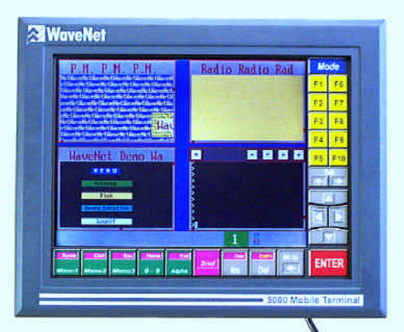
There are four types of display windows; each type is distinguished by a unique window menu
structure:
?? Presentation Manager window (1 only)
?? Radio Manager window (1 only)
?? Session Manager windows (minimum of 1, maximum of 8)
?? Console window (1 only, optional, no menu)
The following figure shows four tiled windows (one of each type). This figure does not show any of the
window menu bars. This figure shows the Presentation Manager (P.M.) window as the active window.
Figure 3-4 Example Multiple Windows
Window Switching
You can switch among the available windows to make a particular window active and have it appear at
the front of all the windows, by using the touch screen overlay keypad.
You can switch from the current active window to the previous activated window by touching the
<2nd> key and then touching the Tab Left key.
You can switch from the current active window to the next available window by touching the <2nd>
key and then touching the Tab Right key.
You must use the <2nd> key each time you repeat a switch operation. Note that the touch screen’s
<2nd> key is equivalent to the <Alt> key on a PC keyboard.
Using Touch Screen Features
5000 Mobile Terminal Product Guide (5000-REV2.21) Chapter 3-14
Alternately (see Chapter 4 - Using the Presentation Manager), you can switch windows by using the
Tasks or Global menu. Also, any particular arrangement of windows can be saved by enabling
security for the windows via the Tasks menu - this allows the windows arrangement to be
automatically presented whenever the MT unit is restarted
Window Controls
Any active window shows five window control buttons in its title bar. Each control button is touch-
sensitive while the title bar itself is not touch-sensitive.
In addition to the active window control buttons, there are two window scroll bar control tabs (~2x2
mm square); one along the bottom border and one along the right border.
The subsequent sections discuss the utilization of the following window control buttons and tabs:
?? Min/Max button (Square symbol)
?? Contrast buttons (Up-arrow & Down-arrow symbols)
?? Location button (Diamond symbol)
?? Size button (Plus-sign symbol)
?? Horizontal Scroll tab
?? Vertical Scroll tab
Some of these controls allow the re-sizing or re-positioning of a window. The re-sizing and re-
positioning controls can be disabled by enabling security for the window (see Chapter 4 - Using the
Presentation Manager).
The following figure shows a generic active window with its controls identified:

Using Touch Screen Features
5000 Mobile Terminal Product Guide (5000-REV2.21) Chapter 3-15
Figure 3-5 The Window Controls
Full/Partial Sizing
You can toggle the active window between the full size and a pre-set partial size, by repeatedly
touching the Min/Max button (Square symbol). A full sized window has no visible window border. A
partial sized window has a visible window border.
The full size covers the complete windows area of the touch-screen.
A partial size is set by using other controls. If there is no pre-set partial size, use the Global menu (see
Chapter 4 - Using the Presentation Manager) for tiling or cascading the current windows - this will
provide a default partial size. Then use the Size button (Plus-sign symbol) for incremental sizing, in
conjunction with the Location button (Diamond symbol) for incremental relocating if required.
Incremental Sizing
You can incrementally resize a partial sized active window by touching the Size button (Plus-sign
symbol), sliding the touch contact point across the touch screen to the desired location, and then
removing the touch which will cause the window to reappear with the new size.
The lower left corner location of the window remains unchanged, while the upper right corner moves to
the selected location. A window sizing operation can result in maintaining the original shape or in
creating a new shape.
Min/Max
Button Contrast
Buttons Location
Button Size
Button
Using Touch Screen Features
5000 Mobile Terminal Product Guide (5000-REV2.21) Chapter 3-16
Positioning
You can drag the active window from one location to another within the display area by touching the
Location button (Diamond symbol), sliding the touch contact point across the touch screen to the
desired location, and then removing the touch which will cause the window to reappear at the new
location.
The upper right corner of the window will be positioned at the new location.
Scrolling
Each partial sized window is framed with a border. Along each of the right vertical and bottom
horizontal borders is a square scroll tab.
You can incrementally scroll the window display by touching the Horizontal or Vertical scroll tab,
sliding the touch contact point along the border to the desired location, and then removing the touch
which will cause the window contents to redisplay at the new scroll setting.
Alternately, you can scroll vertically by using the C_UP or C_DOWN cursor keys in conjunction with
the <2nd> key, or scroll horizontally by using the C_LEFT or C_RIGHT cursor keys in conjunction
with the <2nd> key (see Figure 3-3).
Contrast Level
You can adjust the contrast level of the display area up or down by using any of the two Contrast
buttons (Up-arrow & Down-arrow symbols).
This adjustment facilitates optimal display viewing under particular ambient lighting conditions.
Menu Navigation
Each window type supports a unique pop-up menu structure just below the window’s title bar. A menu
structure consists of a pop-up menu bar and of various drop-down menu item lists.
You can initially pop up the menu bar for any active window by touching the <Mode> key on the
overlay keypad. The first menu item will be highlighted in reverse video - this indicates the current
location of the menu cursor.
You can move the menu cursor (navigate) within the menu of an active window by touching any visible
non-highlighted menu item. Touching a highlighted menu item will display a drop-down list of the next
lower level menu items. Menu items that are indented do not have drop-down lists. Non-indented menu
items do have drop-down lists.
Alternately, you can navigate the menu by using the cursor arrow keys on the overlay keypad for
left/right and up/down movement of the menu cursor.
Once the desired menu item has been located with the menu cursor (highlighted item), you can enable
the menu item by touching it again or by touching the <ENTER> key.
Using Touch Screen Features
5000 Mobile Terminal Product Guide (5000-REV2.21) Chapter 3-17
You can remove each successive menu sub-level and eventually remove the menu bar from the active
window by repeatedly touching the <Mode> key.
The use of the <Mode> key can be password protected to prevent unauthorized access to the menus
(see the section on Security in Chapter 4).
POP-UP KEYBOARDS
The touch screen display area supports a variety of pop-up keyboards that are used for entering data.
The MT unit provides 10 standard pre-defined keyboards and up to 4 user-defined custom keyboards
(see Chapter 4 - Using the Presentation Manager). Only one keyboard can be popped up at a time.
You can pop up any keyboard by touching a specific overlay key or key sequence. These keys can be
user-assigned as hot keys (see the next section on Hot Keys). Hot keys can be exchanged, replaced or
removed. Removing a keyboard hot key assignment is a way of preventing the use of a particular
keyboard.
A list of all the available pop-up keyboards can be viewed via the Presentation Manager’s KB Assign
menu. Initially, the MT unit provides default hot key assignments to 6 of the 10 standard keyboards. A
default hot key assignment can be changed.
A popped up keyboard provides a text entry field with a flashing text cursor. You can enter text in the
entry field by touching the appropriate keys of the pop-up keyboard. Text editing keys are available on
the overlay keypad, as follows:
?? <Del> key for deleting a character
?? <Bk Sp> key for back space operation
?? <Ins> key for inserting a character
To remove any popped up keyboard, touch the hot key(s), which displayed the keyboard, or touch the
screen anywhere outside the keyboard area and within the windows display area.
See Chapter 7 for information on how to design a custom keyboard.
HOT KEYS
A hot key or a hot key sequence is an available and unique overlay key or key sequence that can be
assigned to a valid menu item. You can use these hot keys as an alternate way of calling up the user-
assigned menu items.
You can assign hot keys to:
?? any standard or custom pop-up keyboard.
Using Touch Screen Features
5000 Mobile Terminal Product Guide (5000-REV2.21) Chapter 3-18
?? any Presentation Manager window Global menu item.
Once a hot key sequence has been assigned, you can use these keys, regardless of which window is
active.
Assigning
In general, you can use any overlay key or key sequence that is not already used for a pre-defined
function or hot key, to assign a new and unique hot key.
Typical examples of hot key sequences are as follows:
?? <2nd ><any other available overlay key>
?? <2nd ><Ctrl><any other available overlay key>
?? <2nd ><Ctrl><2nd ><any other available overlay key>
? <2nd ><Ctrl> key sequence is equivalent to a <Ctrl> key and <2nd ><Ctrl><2nd > key
sequence is equivalent to a <Shft> key
Before assigning Hot keys to menu items, you should maximize the size of the active window, pop up
the menu bar , and select the menu item to be hot-keyed.
To assign a Hot key to a selected menu item, use the following typical procedure:
1) Touch the <F2> key. A pop-up field for showing the current hot key sequence will be
displayed adjacent to the menu item.
2) Touch the <2nd> or <Ctrl> or <Shft> key and then touch the <Mode> key or any one of <F1
through F10> keys. The selected hot key sequence will show in the pop-up key field. If this hot
key sequence already exists for another menu item, that menu item function will be enacted. In
this case, touch the <ENTER> key twice and repeat the procedure while choosing another hot
key sequence.
3) Touch the <ENTER> key. The selected menu item will now show the new hot key assignment.
Whenever the assigned hot keys are touched, the corresponding menu item function will be enacted.
The following example procedure illustrates assigning the hot key sequence <2nd><Mode> to the Tile
menu item in the Parameter Manager’s Global menu.
1) Select the Tile menu item.
2) Touch the <F2> key.
3) Touch the <2nd> <Mode> key sequence.
4) Touch the <ENTER> key.
From now on, whenever the key sequence <2nd> <Mode> is touched, the current windows will re-
display in a tiled arrangement.
Using Touch Screen Features
5000 Mobile Terminal Product Guide (5000-REV2.21) Chapter 3-19
Removing
You can remove hot keys from assigned menu items.
To remove a hot key from a selected menu item, use the following procedure:
5) Touch the <F2> key. A pop-up field for showing the current hot key sequence will be
displayed adjacent to the menu item.
6) Touch the <Bk Sp> key (Back Space). The hot key sequence entry in the pop-up field will be
deleted.
7) Touch the <ENTER> key. The selected menu item will no longer show a hot key assignment.
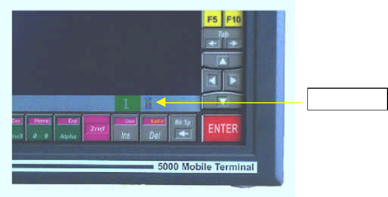
RADIO GAUGES
The MT unit provides a graphic display of diagnostic information about RF communications occurring
between the MT unit and a 7000 Base Controller or 6000 Access Point unit. The graphic display is in
the form of 4 horizontal bar gauges corresponding to 4 labeled indicators that appear on the Status Bar.
(See Figure 3-6) The gauge length indicates the activity level of a communication parameter.
The 4 parameter indicators are:
?? CD (Carrier Detection)
?? RX (Receiving Data)
?? ER (Experiencing DataCom Errors)
?? TX (Transmitting Data)
During normal communications, the gauge bars beside the indicators may vary in length.
Figure 3-6 Radio Gauges
Radio Gauges

Using the Presentation Manager
5000 Mobile Terminal Product Guide (5000-REV2.21) Chapter 4-21
Chapter 4 : Using the Presentation
Manager
This chapter explains how to utilize the Presentation Manager window menu functions of the 5000
Mobile Terminal (MT) unit.
This chapter discusses the menu functions associated with:
?? Windows (listing, arranging, switching, sample graphics)
?? Security Options (passwords, levels)
?? Touch Calibration
?? Keyboard Customization
?? Bar-Code Toggle
?? Voice Channel
?? Saving the Settings
PRESENTATION WINDOW MENUS
The Presentation Manager window supports a menu structure consisting of a pop-up menu bar and a
hierarchy of drop-down lists of menu items. You can touch the <Mode> key to pop up the menu bar.
See the section on Menu Navigation in Chapter 3 for general operational details.
The following table illustrates the scope of all the menu item options:
Tasks Global Local Debug KeyBoard About
Protect
Password
MenuPassword
P.M.
Radio
Session(s)
NextApp
PrevApp
Tile
Casc
Voice
Features
WaveNet
BigWave
WaveDemo

Using the Presentation Manager
5000 Mobile Terminal Product Guide (5000-REV2.21) Chapter 4-22
Tasks Global Local Debug KeyBoard About
Colors
Blocks
Blocksx
WritePrms
TouchCharON
Calibrate
TouchUpdate
CalibrateSave
BarCode
CodeId
AddCR
Touch
Input
Debug
KBDesign
KB Size
KB Def
Row Offset
Key Size
Key Title
KB Assign
Num1KB
Alpha1KB
Alpha2KB
Symb1KB
Alpha3KB
Alpha4KB
Num2KB
FuncKB
VT220KB
F11-F30KB
CKB Assign
KB Handling
KB Review
KB Rename
Eprom
OS
Menu
System
P.M.
Radio
Ansi
Table 4-1 Presentation Window Menu Map
Using the Presentation Manager
5000 Mobile Terminal Product Guide (5000-REV2.21) Chapter 4-23
WINDOWS
You can view a list of the current touch screen windows by touching the Tasks menu bar item to drop
down a menu items list.
Listing
All the menu items below the menu item MenuPassword constitute the list of the current windows.
This list contains the P.M. (Presentation Manager) window entry, the Radio window entry, and at least
one Session window entry. The Session window is indicated by a user-defined name or by the default
name “WaveNet Demo”. There may be up to 8 Session window entries listed. Also, there may be a
Console window entry. The order of the window entries can change with any new activation of a
window.
Adjacent to each window entry, may be an optional assigned security level code (F1, F2, or F3). See
the section on Security in this chapter for details.
Touching any window entry twice, will make that window active (move it to the front of all the
windows).
Arranging
You can arrange all the listed windows in one of two standard ways; tiled or cascaded. Touch the
Global menu bar item, and then touch either the Tile or Casc menu item twice to tile or cascade the
current windows.
Alternately, you may use the assigned hot key sequence (see section on Hot Keys in Chapter 3).
Switching
You can activate either the next available window or the previous available window by touching the
Global menu bar item and then touching the NextApp or PrevApp menu item.
Alternately, you may use the assigned hot key sequence (see section on Hot Keys in Chapter 3).
See also, the section on Window Switching in Chapter 3.
Sample Graphics
You can display one of six pre-defined sample graphics by touching the Local menu bar item, then
touching the Features menu item, and then twice-touching any one of the menu items. These graphic
displays can be used as screen savers. You can clear the current display by touching anywhere in the
Function key region (F1 - F10) of the overlay keypad.
Using the Presentation Manager
5000 Mobile Terminal Product Guide (5000-REV2.21) Chapter 4-24
The named sample graphics are as follows:
?? WaveNet: small WaveNet logo.
?? BigWave: large WaveNet logo.
?? WaveDemo: animation sequence of WaveNet trademarks with brief explanations; includes
a pop-up menu for selecting individual trademark screens.
?? Colors: vertical color test pattern.
?? Blocks: random sequence of various sized and colored blocks.
?? Blocksx: random sequence of high density multi-colored patterns.
SECURITY OPTIONS
Access to certain operations of the MT unit can be secured via user password and configuration level
assignments.
Passwords
There are two types of passwords:
?? Log-on: this prevents unauthorized use of the complete MT unit.
?? Window menus: this prevents unauthorized access to the menu bars of windows, with F2 or
F3 configuration level assignments that have menu protection currently enabled.
Log-on
You may assign a new log-on password if you have access to the P.M. window (i.e. there is no
previous password assigned or a current password is known) and access to the menu bar (i.e. this
window does not have menu protection enabled). Any password is case-sensitive. In addition, you may
remove the current password if you have access to the menu bar.
To assign a new log-on password, use the procedure:
1) Touch the Tasks menu bar item.
2) Touch twice, the Password menu item. A text entry keyboard (New password) will pop up for
about 10 seconds, within which you must enter your password (up to 7 characters) and touch
the <ENTER> key. You will then be prompted with “Confirm password:”; you must re-enter
your password and touch the <ENTER> key before a 10 second time-out.
3) Touch the Local menu bar item.
4) Touch the WritePrms menu item to write the password to the MT unit’s configuration
memory.
Whenever you restart the MT unit, you will be prompted for a password.
To remove the current password, use the procedure:
Repeat all the steps to assigning a new password, except do not enter any text characters.
Using the Presentation Manager
5000 Mobile Terminal Product Guide (5000-REV2.21) Chapter 4-25
Whenever you restart the MT unit, there will be no prompt for a password.
Window Menus
You may assign a new window menus password if you have access to the P.M. window’s menu bar.
Any password is case-sensitive. In addition, you may remove the current password if you know the
password.
This password is used in conjunction with windows which have F2 or F3 configuration level
assignments (see the section on Configuration Levels, in this chapter).
This password can be assigned and saved once, but be enabled each time after each use. This feature
allows a user to quickly protect against unauthorized access to particular window menu bars in the
event that the MT unit is temporarily unattended.
To assign a new menus password, use the procedure:
1) Touch the Tasks menu bar item.
2) Touch twice, the MenuPassword menu item. A text entry keyboard (New password) will pop
up for about 10 seconds, within which you must enter your password (up to 7 characters) and
touch the <ENTER> key. You will then be prompted with “Confirm password:”; you must re-
enter your password and touch the <ENTER> key before a 10 second time-out.
3) Touch the Local menu bar item.
4) Touch the WritePrms menu item to write the password to the MT unit’s configuration
memory.
To remove the current password, use the procedure:
Repeat all the steps to assigning a new password, except do not enter any text characters.
To enable the menu password protection, use the procedure:
1) Touch the Tasks menu bar item.
2) Touch twice, the Protect menu item. This will enable the menu password protection without
having to reboot the MT unit. That is, whenever the <Mode> key is touched for an active
window that is assigned a configuration level of F2 or F3, a text entry keyboard will pop up
and prompt for a password. Once a valid password has been entered, touching the <Mode> key
again will pop up the menu bar, and the protection will be disabled.
Configuration Levels
A configuration security level can be assigned (similar to hot key assignment) to any window listed in
the Tasks drop-down menu items list. There are three possible assignments that define increasing limits
to window functionality:
?? F1 - No limits to window functionality.
?? F2 - Menu password protection is available.
Using the Presentation Manager
5000 Mobile Terminal Product Guide (5000-REV2.21) Chapter 4-26
?? F3 - Only full screen operation is allowed, and menu password protection is available.
The configuration security level of the active window is indicated on the Status Bar. The square
appearing at the left of the radio gauges contains the current security level number.
To assign a configuration security level to a selected window, use the procedure:
1) Touch the Tasks menu bar item.
2) Touch the applicable window menu item.
3) Touch the <F2> key.
4) Touch the <F1> or <F2 > or <F3 > key for level 1or 2 or 3.
5) Touch the <ENTER> key.
See also, the section on Hot Keys, in Chapter 3.
Ensure that the menu password is also assigned (see previous section on Window Menus, in this
chapter).
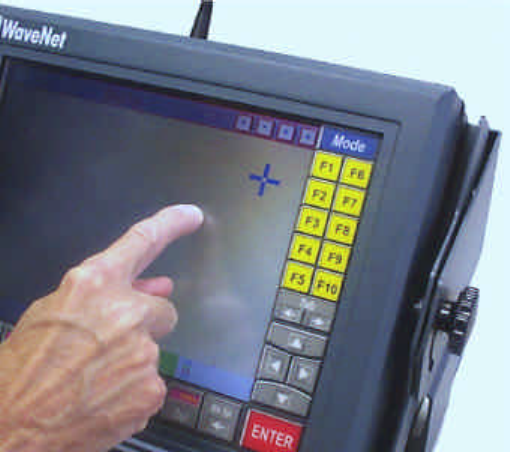
TOUCH SCREEN CALIBRATION
The resistive or capacitive touch membrane covering the display surface may be calibrated for position
accuracy. This procedure is not required on a regular basis and should only be undertaken if you are
certain the calibration has drifted over time. Reasons for it drifting may include exposure to extremes
of temperature or an extended shelf life where the pre-set calibration has been lost.
Checking for Calibration
Place your finger or other object in the case of resistive screens on the touch screen. A cursor should
appear underneath if the screen is in calibration. If not the cursor will appear offset somewhere else on
the screen.
Using the Presentation Manager
5000 Mobile Terminal Product Guide (5000-REV2.21) Chapter 4-27
Figure 4-1 Offset Cursor
There are degrees of drift in calibration. If the calibration is not serious you will be able to use the
screen to re-calibrate. Do this by dragging your finger across the screen until the cursor is over the
menu item you want. Where the drift has been large or where the settings have been lost you will need
to use a keyboard to reset them.
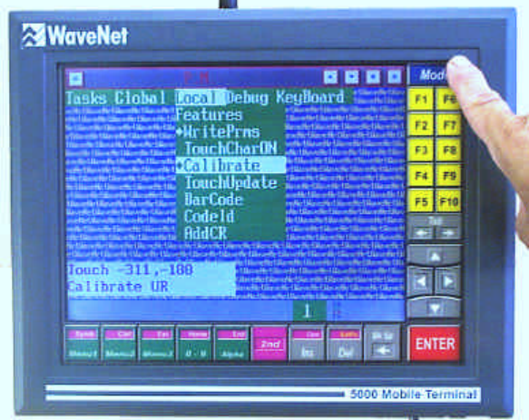
Using the Touch Screen to Re-Calibrate
Using the Presentation Manager window select the Local option. This will display a menu item named
‘Calibrate’. Touch this twice to activate the option. A window opens up on the lower left portion of
the screen containing values representing the touch co-ordinates. You are asked to touch the upper
right (UR) corner and then the lower left (LL) corner in turn. This action gives the unit co-ordinates
for the screen. In the Local Menu select ‘WritePrms’ to save the new settings. Complete the process by
touching ‘Mode’ to exit the Local Menu.
If your unit has a resistive screen there is an additional step. In the Tasks Menu select ‘Protect’ and
then exit.
Using the Presentation Manager
5000 Mobile Terminal Product Guide (5000-REV2.21) Chapter 4-28
Figure 4-2 Touching the UR Corner
? The Upper Right (UR) and Lower Left (LL) correspond to the viewing screen not the
corner of the enclosure.
Using a Keyboard to Re-calibrate
Plug a standard keyboard into the port in the bottom of the unit. Press Alt+M to access the menu.
From there use the arrow keys to navigate the menu items and follow the procedure outlined in the
preceding paragraph – Using the Touch Screen to Re-calibrate.
Removing the Co-ordinate Window
The cursor co-ordinate window remains on the screen. To remove it Select ‘Touch’ in the Debug
Menu and then ‘Mode’ to exit. For capacitive units this completes the calibration procedure.
BARCODE TOGGLING
The bar code scanner may be toggled on or off at any time. The action of going from one state to the
other is known as ‘toggling’.
To use this feature select the Program Manager window and in it the Local Menu item.
From the Local menu select BarCode. A diamond will appear against it indicating selection.
Using the Presentation Manager
5000 Mobile Terminal Product Guide (5000-REV2.21) Chapter 4-29
Saving the Setting
To save your new configuration select ‘WritePrms’ from the same menu list. Your unit however does
require re-booting for the new parameters to take effect. Do this by touching <2nd>twice, powering off
and then powering up.
Using the Radio Manager
5000 Mobile Terminal Product Guide (5000-REV2.21) Chapter 5-31
Chapter 5 : Using the Radio Manager
This chapter explains how to utilize the Radio Session Menu Bar of the 5000 Mobile Terminal unit.
This chapter discusses the menu items associated with:
?? Setup
?? Test Options
?? Monitor Options
?? The AssignKey
?? RF Site Survey Keys
? CAUTION! Procedures detailed in this Chapter should only be performed by certified WaveNet
technicians. Unauthorized use of the radio spectrum may occur, or significant degredation of
the 5000’s performance may result, or significant degradation of the WaveNet Wireless LAN
system may result if the following configuration parameters are not correctly set.
RADIO SESSION MENU BAR
The Radio Manager window supports a menu structure consisting of a pop-up menu bar and a
hierarchy of drop-down lists of menu items. When this window is active, you can press the <Mode>
key to activate the menu bar. See the section on 'Menu Navigation' in Chapter 3 for general operational
details.
Narrow Band Radio Systems
The following outline illustrates the menu bar and the scope and organization of the menu item which
are unique to WaveNet Wireless LAN Narrow Band systems:
Menu Bar Item 1st Sub-Menu 2nd Sub-Menu Comments
SETUP
Parameters Header Size Size (in characters) of synchronization header
(default = 12)
Channel RF channel used when the 3000 first powers up
ChanSelect RF channels which can be switched to
(consequetive numbers indicate order) when the
5000 performs cellular channel switching
Node Address Unique radio data network address for the 3000
14.4 14.4 Kbps radio data link speed
9600 9600 bps radio data link speed
7200 7200 bps radio data link speed
Frequencies 1: Center channel frequency for Radio Channel 1
2: Center channel frequency for Radio Channel 2

Using the Radio Manager
5000 Mobile Terminal Product Guide (5000-REV2.21) Chapter 5-32
Menu Bar Item 1st Sub-Menu 2nd Sub-Menu Comments
3: Center channel frequency for Radio Channel 3
4: Center channel frequency for Radio Channel 4
5: Center channel frequency for Radio Channel 5
6: Center channel frequency for Radio Channel 6
7: Center channel frequency for Radio Channel 7
8: Center channel frequency for Radio Channel 8
SaveParam’s Save current radio configuration in memory
CloneParam’s Debug Turns on additional on-screen reporting during the
parameter cloning process
NewVer Sets the version number to be used after the cloning
process
OldVer Sets the version number of current parameters
AllVersions Clones parameters, regardless of version numbers
Reboot Configures cloned parameter recepient terminal to
re-start after cloned parameters received
Clone Starts the cloning process
TESTS Frequency Sets the frequency of the tests
Adjust Power Adjusts the radio RF ouput power through use of
the TAB key when selected.
Speaker Adjusts the speaker volume through use of the TAB
key when selected
Deviation Adjusts the radio deviation through use of the TAB
key when selected
Frequency Adjusts the radio frequency error through use of the
TAB key when selected
StopAll Stops all radio functions when selected
StopTest Stops the current test when selected
XmitLong Transmits a long test pattern when selected
RcvAnalog Receives an analog signal when selected
Voice Turns on voice operation when selected
RcvMsg Receives a data message when selected
XmtBro Continuously broadcasts a test message when
selected
XmtBro(20) Broadcasts a test message 20 times when selected
XmtMsg Transmit the entered characters when selected
MONITOR Data Receive Provides real time display of received data
Xmit Provides real time display of transmitted data
Error Provides real time display of received data in error
Stats Displays current radio statistics
Info Displays summary of radio configuration
RcvBro Provides real time display of received network
broadcasts
Mac Provides real time display of MAC level activity
Net Provides real time display of NET level activity
Rout Provides real time display of current routes
Sess Provides real time display of SESS level activity
ASSIGNKEY Assigns text string of up to 15 characters to a Hot
Key (used with radio tests)

Using the Radio Manager
5000 Mobile Terminal Product Guide (5000-REV2.21) Chapter 5-33
900 MHz Radio Systems
The following outline illustrates the menu bar and the scope and organization of the menu item which
are unique to WaveNet Wireless LAN 900 MHz Spread Spectrum systems:
Menu Bar Item 1st Sub-Menu 2nd Sub-Menu Comments
SETUP
(Spread Spectrum)
Parameters Channel RF channel used when the 3000 first powers up
ChanSelect RF channels which can be switched to
(consequetive numbers indicate order) when the
5000 performs cellular channel switching
Node Address Unique radio data network address for the 3000
SaveParam’s Save current radio configuration in memory
CloneParam’s Debug Turns on additional on-screen reporting during
the parameter cloning process
NewVer Sets the version number to be used after the
cloning process
OldVer Sets the version number of current parameters
AllVersions Clones parameters, regardless of version numbers
Reboot Configures cloned parameter recepient terminal
to re-start after cloned parameters received
Clone Starts the cloning process
TESTS Adjust Power Not functional in 900 MHz radio systems.
Speaker Not functional in 900 MHz radio systems.
Deviation Not functional in 900 MHz radio systems.
Frequency Not functional in 900 MHz radio systems.
StopAll Stops all radio functions when selected
StopTest Stops the current test when selected
XmitLong Transmits a long test pattern when selected
RcvAnalog Receives an analog signal when selected
Voice Not functional in 900 MHz radio systems.
RcvMsg Receives a data message when selected
XmtBro Continuously broadcasts a test message when
selected
XmtBro(20) Broadcasts a test message 20 times when selected
XmtMsg Transmit the entered characters when selected
MONITOR Data Receive Provides real time display of received data
Xmit Provides real time display of transmitted data
Error Provides real time display of received data in
error
Stats Displays current radio statistics
Info Displays summary of radio configuration
RcvBro Provides real time display of received network
broadcasts
Mac Provides real time display of MAC level activity
Net Provides real time display of NET level activity
Rout Provides real time display of current routes
Sess Provides real time display of SESS level activity
ASSIGNKEY Assigns text string of up to 15 characters to a Hot
Key (used with radio tests)

Using the Radio Manager
5000 Mobile Terminal Product Guide (5000-REV2.21) Chapter 5-34
2.4 GHz (Aironet) Radio Systems
The following outline illustrates the menu bar and the scope and organization of the menu item which
are unique to WaveNet Wireless LAN 2.4 GHz (Aironet) Spread Spectrum systems:
Menu Bar Item 1st Sub-Menu 2nd Sub-Menu Comments
SETUP Parameters Node Address Not used for Aironet 2.4 GHz systems. Normally
set to 1.
SaveParam’s Save current radio configuration in memory
CloneParam’s Debug Turns on additional on-screen reporting during
the parameter cloning process
NewVer Sets the version number to be used after the
cloning process
OldVer Sets the version number of current parameters
AllVersions Clones parameters, regardless of version numbers
Reboot Configures cloned parameter recepient terminal
to re-start after cloned parameters received
Clone Starts the cloning process
MONITOR Stats Displays current radio statistics
Info Displays summary of radio configuration
Mac Provides real time display of MAC level activity
Net Provides real time display of NET level activity
Rout Provides real time display of current routes
Sess Provides real time display of SESS level activity
ASSIGNKEY Assigns text string of up to 15 characters to a Hot
Key (used with radio tests)
RADIO\SETUP MENU ITEMS
Radio Operational Parameters (Parameters Menu Items)
You can modify any of the main radio parameters by selecting the Parameters menu item in the Setup
menu.
The radio parameters are as follows (Narrow Band):
HeaderSize The number of radio message headers to be transmitted before actual message
transmission begins (default = 12).
Channel The first radio channel number used when the 5000 initializes (default = 1).
ChanSelect The channels and which the 5000 can search when in cellular operation (default =
1, non-cellular mode). Since any channel number is a single digit, the channel
numbers can be entered with no spaces or commas. For example, 234
represents channel numbers 2, 3, and 4. The order of entry is the search order used
by the 3000 when a cellular search is performed.
NodeAddress A unique network node address number (1 - 65555) for the 5000.

Using the Radio Manager
5000 Mobile Terminal Product Guide (5000-REV2.21) Chapter 5-35
Bit Rate One of three possible rates: 14.4 Kbps, 9600 bps, or 7200 bps. Only one can be
selected.
The first four parameters are each entered via a numeric keyboard which pops up when the
corresponding menu item is selected. The fifth parameter is one item selected from the three
corresponding menu items.
These parameters are only slightly different for the WaveNet Wireless LAN 900 MHz Spread
Spectrum systems:
Channel The first radio channel number used when the 5000 initializates (default = 1).
ChanSelect The channels and which the 5000 can search when in cellular operation (default =
1, non-cellular mode). Since any channel number is a single digit, the channel
numbers can be entered with no spaces or commas. For example, 234
represents channel numbers 2, 3, and 4. The order of entry is the search order used
by the 3000 when a cellular search is performed.
NodeAddress A unique network node address number (1 - 65555) for the 5000.
In the WaveNet Wireless LAN Spread Spectrum systems, the Header and Bit Rate parameters are not
used, as these configurations are pre-set.
There are few parameters necessary for WaveNet Wireless LAN 2.4 GHz (Aironet) Spread
Spectrum systems. These parameters are available only on the Command Line Interface, accessible on
the Console Port of the terminal:
Command * Syntax Value
Power Save Mode > air CP <value> 0 = CAM (default)
1 = PSP
2 = Fast PSP
Radio SSID > air CS <value> Text Name (default = tsunami)
Identification Name > air CN <value> Text Name (default = none)
* Refer to PC4500 User Manual
? “> air P” is used to save any changed parameter settings.
? The SSID in the Aironet Access Point configuration must match the SSID configured in
the WaveNet Terminal. If this condition is not met, then the WaveNet terminal will not
“associate” with the Aironet Access Point and no radio data communications will result.
? If no SSID (SSID of “”) is set in the WaveNet Terminal, then it will freely associate with
any Aironet Access Point. However, this may not be desirable in all installations.
Using the Radio Manager
5000 Mobile Terminal Product Guide (5000-REV2.21) Chapter 5-36
Narrow Band Frequencies (Frequencies Items)
If a Narrow Band radio has been installed, the available radio frequencies are determined by the
frequencies licensed and assigned to the site. These frequencies need to be assigned to specific
channels. The assignments can be in any order.
You may assign a licensed frequency to a channel by selecting the Frequencies menu item in the Setup
menu, which will produce a list of 8 channel numbers. Selecting a 'channel number' menu item will pop
up a numeric keyboard. Enter a frequency (MHz) in the format of xxx.xxxx.
Parameter Cloning (CloneParam’s Items)
The WaveNet Wireless LAN technology allows the cloning of one 5000’s parameter setup (excluding
terminal-unique parameters) onto one or more other 5000s in the network, via radio data transmission.
To clone the current parameter setup, use the procedure:
1) Select the CloneParam’s menu item in the Setup menu.
2) Select the NewVer menu item, which will pop up a numeric keyboard. Add 1 to the current
value and enter the new value.
3) Select the OldVer menu item, which will pop up a numeric keyboard. Add 1 to the current
value and enter the new value.
4) Enable each of the menu items, Debug, AllVersions, and Reboot.
5) Activate the menu item Clone - this will cause the 5000 to transmit it’s current parameter
setup to other receptive 5000s.
RADIO\TEST MENU ITEMS
Test options are available for analyzing or troubleshooting radio operations. Testing is done by
WaveNet certified technical support personnel. The test parameters are accessed via the Tests menu
and are not applicable to all radio systems. This menu allows the following actions:
?? Selecting a test radio frequency (Frq:).
?? Adjusting RF Power output, Speaker volume level, Deviation, or frequency (Freq.) error. Each
of these adjustments are accomplished by pressing the Tab Right key for increasing a value or
the Tab Left key for decreasing a value.
?? Entering a test message (XmtMsg) up to 8 characters. The message will show on the menu item.
?? Broadcasting (XmtBro) the test message continuously.
?? Broadcasting (XmtBro(20)) the test message 20 times only.
?? Transmitting (XmitLong) a ‘long’ test message.
?? Stopping the current test (StopTest).
?? Stopping all radio operations (StopAll).
?? Receiving messages (RcvMsg).
?? Enabling/disabling Voice operation which disables/enables data operation. This causes the radio
(Narrow Band only) to switch to Channel 8 for analog voice operation.
Using the Radio Manager
5000 Mobile Terminal Product Guide (5000-REV2.21) Chapter 5-37
?? Receiving an analog signal (RcvAnalog).
RADIO\MONITORING MENU ITEMS
Data monitoring options are available for analyzing or troubleshooting communication operations.
Monitoring is usually done by WaveNet certified technical support personnel. The monitoring options
are accessed via the Monitor menu (not available in all radio systems). This menu allows the
following actions:
?? Enabling/disabling the monitoring of up to three kinds of Data; Receive, Transmit (Xmit), or
Error.
?? Displaying of radio statistics (Stats).
?? Displaying of radio configuration information (Info).
?? Displaying of receive broadcast (RcvBro) history.
?? Enabling/disabling MAC layer (Mac) monitoring.
?? Enabling/disabling NET layer (Net) monitoring.
?? Enabling/disabling route information (Rout) monitoring.
?? Enabling/disabling SESSION layer (Sess) monitoring.
RADIO/ASSIGNKEY MENU ITEMS
The AssignKey menu item provides a way of assigning a text string up to 15 characters to any key on
the overlay keypad. The assignment allows the repeated entry of a text string by using only one or two
keys.
RF SITE SURVEY KEYS
Narrow Band and 900 MHz Radio Site Surveys
An RF site survey involves the transmitting of pre-defined messages to a reference terminal which
returns the messages - the ensuing statistics provide the RF coverage measurements.
Three Function keys F3, F4, and F8 are reserved for RF site surveys whenever the Radio window is the
active window. A site survey is done by WaveNet certified technical support personnel. These function
keys will only perform the described operations when the Menu Bar is not being used.
Pressing the F3 key will pop up (or remove) a dialogue box for entering site identification information
and modifying any site survey parameters. Pop-up keyboards are used for entering data. You may
select (activating a text cursor) any data field by pressing it or move across the data fields by pressing
the cursor arrow keys or the tab keys.
Using the Radio Manager
5000 Mobile Terminal Product Guide (5000-REV2.21) Chapter 5-38
Pressing the F4 key will toggle the text cursor between the dialogue box and the Radio window screen.
The text cursor must be removed from the dialogue box before using the F3 key to remove the dialogue
box.
Pressing the F8 key will start (or stop) the site survey test.
2.4 GHz (Aironet) Radio Site Surveys
Site survey facilities described above are not available with 2.4 GHz (Aironet) radio systems. The
Aironet 2.4 GHz radio system is an IP based radio network and must use IP based utilities. One such
utility, recommended for site survey use is the PING utility.
To use the PING utility, use the following steps:
1) Turn on the internal barcode reader in the Program Manager Menu system. If an internal
barcode reader is already installed, then this step is not necessary. Save the parameters and
reboot the terminal.
2) Switch to the CONSOLE task (automatically starts when the internal barcode reader is
enabled).
3) Use the DNS task to set a DNS Name for the test IP ( > dns set host <Name> <IP Number>.
Note that the
4) Type “>ping <Name>” and ENTER to start the PING test. Note the <Name> is case
sensitive.
Following is an example of a PING test:
>tcp ip addr en0
tcp>en0 IP Address is 192.168.0.40
>
>dns set host AP15 192.168.0.15
>dns save
dns>Host table saved (0)
dns>Port table saved (0)
>
>ping -c10 AP15
ping>PING AP15: 64 data bytes
ping>72 bytes from AP15: icmp_seq=0. time=50. ms
ping>72 bytes from AP15: icmp_seq=1. time=40. ms
ping>72 bytes from AP15: icmp_seq=2. time=40. ms
ping>72 bytes from AP15: icmp_seq=3. time=40. ms
ping>72 bytes from AP15: icmp_seq=4. time=40. ms
ping>72 bytes from AP15: icmp_seq=5. time=40. ms
ping>72 bytes from AP15: icmp_seq=6. time=40. ms
ping>72 bytes from AP15: icmp_seq=7. time=40. ms
ping>72 bytes from AP15: icmp_seq=8. time=40. ms
ping>72 bytes from AP15: icmp_seq=9. time=40. ms
ping>
ping>----AP15 PING Statistics----
ping>10 packets transmitted, 10 packets received, 0% packet loss
ping>round-trip (ms) min/avg/max = 40/41/50
>

Using the Radio Manager
5000 Mobile Terminal Product Guide (5000-REV2.21) Chapter 5-39
Note that the PING command “ping –c10 AP15” can be easily set as a command key to save retyping
the command each time a test is conducted.
In general, 2.4 GHz systems are characterized by a rapid decrease in signal quality when the maximum
communications distance is exceeded (as dictated by environmental conditions). If the PING test does
not yield consistent results, and stops before the pre-set number of pings is completed, then the
coverage is likely not sufficient for normal operation.
As well, 2.4 GHz are easily blocked by metallic and non-metallic objects. Ensure that any failure of
the PING test (indicating inadequate coverage) is not simply a small “dead zone” by moving the
terminal several feet to a alternate location and repeat the test.
RADIO STATISTICS SUMMARY
Pressing the F2 key when the Menu Bar is not being used will display a summary of current radio
statistics, which is updated in real time during the display.
Narrow Band & 900 MHz Radio Systems
The following table explains the labels used for the displayed message statistics.
Statistic Explanation
Rcv msg The total number of messages received.
for us The total number of messages directed to the unit
of interest.
Chars The total number of characters decoded.
Xmtmsg The total number of messages transmitted from
the unit.
re-xmit The number of re-transmits the unit had to
perform.
Xmterr The number of times the unit needed to transmit
but was not ready – most likely a hardware fault.
err:tot The total number of errors.
Crcerr Indicates the number of times bits were decoded
but did not match the crc.
Decerr Only part of the message was decoded.
Tmout A message was expected but did not arrive –
decoding failed due to radio errors or interference.
Cdoff The total number of times in which the carrier
detect was active, but no bits were decoded. This
indicates other radio activity.
Glitch Event count in which the carrier detect went active
for a short period of time due to extraneous radio
activity.

Using the Radio Manager
5000 Mobile Terminal Product Guide (5000-REV2.21) Chapter 5-40
Statistic Explanation
Xmtbro The number of “broadcasts” the unit has sent.
The bottom of the statistic display also provides the following information:
1) The node number of the terminal
2) The channel of operation
3) The average response time (historical)
4) The current “valid” routes, through either wired or wireless 7000 Base Controllers, sensed by
the terminal (the top route is the route currently in use). Routes through wireless repeaters are
indicated as multiple 7000 Base Controllers (i.e. B1 B20), wile routes not using wireless
repeaters are indicated as single 7000 Base Controllers (i.e. B2).
The final set of statistics show various indicators (tm, rx, qt, rssi) of the “quality” of the current route
in use.
Aironet 2.4 GHz Radio System
Statistic Explanation
Rcv msg Not Used.
for us Not Used.
Chars Not Used.
Xmtmsg Not Used.
Rcvsync Indicates the number of sync messages received from an Access Point when
terminal data traffic is idle.
Rcverr Not Used.
Ignored Indicates the number of valid messages received but not addressed to the
terminal
Recv Indicates the number of messages received
Xmit Indicates the number of messages transmitted
800 (Recv) Indicates the number of 800 type Ethernet packets received.
800 (Xmit) Indicates the number of 800 type Ethernet packets transmitted.
806 (Recv) Indicates the number of 806 type Ethernet packets received.
806 (Xmit) Indicates the number of 806 type Ethernet packets transmitted.
Chars (Recv) Indicates the number of Ethernet characters received..
Chars (Xmit) Indicates the number of Ethernet characters transmitted.
Serial (Recv) Indicates the number of serial line characters received.
Serial (Xmit) Indicates the number of serial line characters transmitted.
Chars (Recv) Indicates the total number of characters received.
Chars (Xmit) Indicates the total number of characters transmitted.
The next line in the statistics display gives the Aironet PC Card type designator as read from the PC
Card memory, and the Ethernet MAC Address of the PC Card.
Using the Radio Manager
5000 Mobile Terminal Product Guide (5000-REV2.21) Chapter 5-41
The bottom of the statistic display also provides the following information:
1) The node number of the terminal (not used for 2.4 GHz radio systems)
2) The channel of operation (typically 2.4 for 2.4 GHz)
3) The serial interface speed (typically 115200 bps)
In addition, the command line of the console connection can be used for additional monitoring, for
example:
>air s
air>SSID "WaveNet" MAC 00409613de23, Mode 3f Errc 0 SigQ 46
air>BSSI "AP4500_Photocopy" MAC 0040961449c5 000000000000 000000000000
000000000000
air> BeaconP/DTIM 100/1 HopP/# 200/1 Chan 6/0
The above shows the following information:
?? Terminal Station Identifier (SSID)
?? Terminal MAC Address
?? Base Station Station Identifier (the Access Point that the terminal is currently associated with)
?? Access Point MAC Address
?? Number of Hops to the Access Point that has direct access to the Ethernet backbone
?? Channel of operation
? If the WaveNet terminal has no SSID configured (SSID of “”) it will freely associate with any
Aironet Access Point. In this case, the above command will simply show the SSID of the
Aironet Access Point that the WaveNet terminal is currently associated with.
In addition, the following command can also be used for additional information:
>air a
air>Status: -BO -BI -RTS CTS reset 1 dcd 221/103 cts 1 baud 76800
air>xmt/err 110.110<962>/0 rcv/err 103.0<783>/0.0.74 Sync.Poll 102.613
This command gives information about:
?? Terminal to radio card interface speed
?? Transmitted messages and errors
?? Received messages and errors

Using the Session Manager
5000 Mobile Terminal Product Guide (5000-REV2.21) Chapter 6-43
Chapter 6 : Using the Session Manager
This chapter explains how to utilize the Session Manager window menu functions of the 5000 Mobile
Terminal unit.
This chapter discusses the menu functions associated with:
?? Emulation Setting
?? Communication Settings
?? Display Settings
?? Pop-up Keyboard Settings
?? Barcode Tab Toggle
?? Cursor Captive Toggle
?? Serial I/O Toggle
?? Session Cloning
?? About Current Session
The terminal supports a minimum of 1 session window and a maximum of 8 session windows. Multiple
session windows are enabled via session window cloning. Each window supports an identical menu
structure. Each window can be assigned a user-defined name.
SESSION WINDOW MENUS
A Session Manager window supports a menu structure consisting of a pop-up menu bar and a
hierarchy of drop-down lists of menu items. You can touch the <Mode> key to pop up the menu bar.
See the section on ‘Menu Navigation’ in Chapter 3 for general operational details.
The following outline illustrates the menu bar and the scope and organization of the menu item options.
Setup About
Emulation Ver
WaveNet Node
VT220 Sess
Unix
Communication
Service
5250
TN5250
3270
TN3270
Telnet
PC Link
PC Link[2]

Using the Session Manager
5000 Mobile Terminal Product Guide (5000-REV2.21) Chapter 6-44
PC Link[3]
SLP-TCP
Demo
Session
Copy
Title
Rename
Delete
Host ID = 0
8 Bit = Yes
Display
Page Caching
Character Set
ASCII
Chinese
Korean
Font
F8x8
F8x16
TF8x16
F16x32
TF16x32
Korean
Chinese
Font Map
F8x8 =1
F8x16 =2
TF8x16 =3
F16x32 =4
TF16x32 =5
Korean =0
Chinese =6
Screen size
Rows =25
Columns =80
Origin Scroll
Keyboard
Pop-up
Manual
Always
If Active
On Touch
Barcode Tab
Cursor Captive
Other
Serial I/O = NO
Using the Session Manager
5000 Mobile Terminal Product Guide (5000-REV2.21) Chapter 6-45
Table 6-1 The Session Manager Window Menu Structure
EMULATION SETTING
The MT unit supports three types of host application session terminal emulators:
?? WaveNet (ANSI)
?? VT220
?? Unix
You can select one of the emulators by selecting the Emulation menu item in the Setup menu, and then
touching twice the chosen emulation menu option.
The VT220 emulation allows the Function keys F1 - F4 to be used for the VT220 PF1 - PF4 keys.
COMMUNICATION SETTINGS
The communication settings for each session window involve:
?? Selecting the desired host communications service.
?? Entering the required host identifier.
?? Setting the number of data bits.
You can access these settings by selecting the Communication menu item in the Setup menu.
Host Service
Touch the Service menu item to display a list of possible host services. Touch twice to enable one of
the following communication services:
?? 5250 IBM 5250 data stream via SDLC/SNA.
?? TN5250 IBM 5250 data stream via TCP/IP/Telnet.
?? 3270 IBM 3270 data stream via SDLC/SNA.
?? TN3270 IBM 3270 data stream via TCP/IP/Telnet.
?? Telnet ANSI data stream via TCP/IP/Telnet.
?? PC Link ANSI data stream via RS-232/WaveNet SIOP, per host 1.
?? PC Link[2] ANSI data stream via RS-232/WaveNet SIOP, per host 2.
?? PC Link[3] ANSI data stream via RS-232/WaveNet SIOP, per host 3.
?? SLP-TCP ANSI data stream via TCP/IP/WaveNet SLP.
?? Demo ANSI data stream per WaveNet host simulation.
Using the Session Manager
5000 Mobile Terminal Product Guide (5000-REV2.21) Chapter 6-46
Host ID
The host identification entry links the MT unit to the 7000 Base Controller that connects to the desired
host. The chosen host ID must be the same as that assigned to the appropriate Base Controller. Any
session window can reference the same or different host ID used by another session window. The
default host ID is 0.
You can enter the host ID number via the Host ID menu item, which will pop up a numeric keyboard.
The entered ID will show in the menu item.
Data Bits
You can use the menu item 8 Bit= to set the number of data bits per data byte to either 7 or 8. Touch
the menu item, which will pop up a keyboard, and enter Yes for 8 or No for 7. The default number is
8. Yes or No will show in the menu item.
DISPLAY SETTINGS
You can customize the display characteristics of a session window in terms of:
?? Page Caching
?? Character Set
?? Font
?? Font Map
?? Screen Size
?? Origin Scroll
You can access these customization options by selecting the Display menu item in the Setup menu.
Page Caching
You can set the number of pages for caching purposes via the Page Caching menu item which will pop
up a numeric keyboard. The entered number of pages will show in the menu item. The new value will
take effect upon rebooting the MT unit.
The default value is 0, which denotes that page caching is disabled.
Character Set
The MT unit can support one or more different character sets, depending on installation requirements
and available memory. The current available character sets are:
?? ASCII
Using the Session Manager
5000 Mobile Terminal Product Guide (5000-REV2.21) Chapter 6-47
?? Chinese
?? Korean
A character set determines how the terminal will interpret the ASCII characters sent from a host
computer, and establishes the graphical rendition the terminal will use for representing information
from the host computer.
?? Selecting ASCII will enable use of either the F8x8, F8x16, TF8x16, F16x16, F16x32,
TF16x32 and 24x24 English fonts, with ASCII single byte processing. Only these fonts should
be used with this character set.
?? Selecting Chinese will enable use of the 24x24 Chinese standard font, with double byte ASCII
processing enabled through use of MSB signaling. Only the 24x24 Chinese font should be used
with this character set.
?? Selecting Korean will enable use of the 16x16 Korean standard font, with double byte ASCII
processing enabled through use of MSB signaling. Only the 16x16 Korean font should be used
with this character set.
The font references are names of font types that can be supported, depending on installation
requirements and available memory. The current available fonts are listed via the Font menu item. See
the section on ‘Font’ in this chapter.
Font
You can list the current available font types by selecting the Font menu item. You can enable the
specific font by touching twice the appropriate menu item.
When selecting a font, you need to account for the screen size generated by the host and expected by
the terminal. See also, the section on ‘Screen Size’ in this chapter.
Font Map
You can make use of font identifiers within host application sessions. The font identifiers are numbers
that represent each of the fonts listed via the Font menu item. The MT unit provides a default set of
identifiers. The identifiers are listed via the Font Map menu item. You may modify the identifiers via
the appropriate menu item, which will pop up a keyboard. The entered identifier will show in the menu
item.
Screen Size
You can select a window screen size by selecting the number of character rows and the number of
character columns that would be visible in a full (maximized) window. The screen size settings need to
be consistent with the font type selected in the Font menu (see the section on ‘Font’ in this chapter).
The following table correlates example font options with the screen size parameters, Rows and
Columns.
Using the Session Manager
5000 Mobile Terminal Product Guide (5000-REV2.21) Chapter 6-48
Font Rows Columns
F8x8 24 80
F8x16 24 80
TF8x16 24 80
F16x32 12 40
TF16x32 12 40
24x24 24 80
Table 6-2 Font and Screen Sizes
The screen size settings depend on the host application. If the host screen size is larger than that of the
terminal window, the terminal will truncate that screen display. Recommended sizes are either 12 rows
x 40 columns or 24 rows x 80 columns.
You can modify the screen size settings by touching twice the Screen Size menu item and then
touching the Rows or Columns menu item. A numeric keyboard will pop up. Enter an appropriate
value. The value will show in the menu item.
Origin Scroll Toggle
It is possible that during a host application session the text cursor will end up off-screen. You could
use the cursor arrow keys and/or tab keys to locate the cursor, but this could be time-consuming. The
origin scroll toggle is an alternate way of keeping the cursor on-screen.
Whenever the Origin Scroll menu item is enabled, the cursor will automatically return to the origin
(0,0) coordinates at the upper left corner of the window screen if the cursor is about to go off-screen.
POP-UP KEYBOARD SETTINGS
You can customize the pop-up action for the available keyboards in terms of four options:
Manual Must touch the appropriate selection key.
Always An appropriate keyboard will automatically pop up whenever there is a need
for one.
If Active An appropriate keyboard will pop up whenever an input field is made active
On Touch The appropriate keyboard will pop up whenever you touch an input field.
You can access the pop-up options by selecting the Pop-Up menu item in the Keyboard menu.
Using the Session Manager
5000 Mobile Terminal Product Guide (5000-REV2.21) Chapter 6-49
BARCODE TAB TOGGLE
You can use the BarCode Tab menu item in the Keyboard menu to enable or disable the automatic
tabbing of the text cursor to the next data entry field for bar code scanner application sessions.
Cursor Captive Toggle
You can use the Cursor Captive menu item in the Keyboard menu to enable or disable the automatic
constraining of the text cursor to the current data entry field until a valid entry is made.
SERIAL I/O TOGGLE
You can use the Serial I/O menu item in the Other menu to enable or disable the Scanner Port, which
is RS-232 compatible.
Touching the Serial I/O menu item will pop up a keyboard for entering Yes to enable or No to disable
the port. The entry will show in the menu item.
Note that the Scanner Port is also enabled or disabled via the BarCode menu item in the Presentation
Manager window’s Local menu.
SESSION CLONING
The MT display is capable of presenting multiple sessions originating from multiple and disparate
hosts. This feature lets mobile operators switch between applications on different hosts or switch
between different sessions originating from the same host or any combination of both with minimal
disruption to the user’s work flow. Switching between sessions requires that the user simply touch the
desired session window in order to activate that session.
The number of sessions supported per terminal is limited to eight. All eight session windows plus the
Presentation Manager and Radio Manager windows can be displayed simultaneously on the touch
screen by tiling the windows. However, it is recommended that any tiled display be limited to four
windows or less; the visibility and usefulness of these windows degrades as their relative size
diminishes.
Once the multi-session capability has been activated and configured, the terminal display can be frozen
for the desired look by using the password protection utility in the Presentation Manager. Upon power
up, users will see only the authorized pre-configured screens.

Using the Session Manager
5000 Mobile Terminal Product Guide (5000-REV2.21) Chapter 6-50
Cloning a Session Window
You can clone the current active session window by using that window’s
Setup/Communication/Session menu and then using the procedure:
1) Touch twice the Session menu item, which will display the Copy menu item.
2) Touch the Copy menu item which will display the Title= menu item.
3) Touch the Title= menu item which will pop up a keyboard.
4) Enter a distinctive title name for the new session window.
5) Reboot the MT using the <2nd><2nd><OFF><ON> key sequence (see Chapter 2).
6) Tile the windows to view the new session window.
You can also rename the title of the new session window by using that window’s
Setup/Communication/Session menu and then selecting the Session menu item, which will display the
Rename menu item. Touch the Rename menu item that will display the current title. Touch the title
item, which will pop up a keyboard. Enter a new title. This title will appear in the title bar of the
window.
Deleting a Cloned Session Window
You can delete an active cloned session window by using that window’s
Setup/Communication/Session menu and then using the procedure:
1) Touch twice the Session menu item, which will display the Delete menu item. The Delete item
will not appear if the current window is the original session window.
2) Activate the Delete menu item.
3) Reboot the MT using the <2nd><2nd><OFF><ON> key sequence (see Chapter 2).
4) Tile the windows to view the existing session windows. The deleted window will have been
removed.
ABOUT THE CURRENT SESSION
You can obtain specific information about a particular session by activating the appropriate session
window, popping up the menu bar using the <Mode> key, and touching twice the About menu bar
item. Four bits of information is displayed; for example:
Ver=19970409 Version of the software installed in the MT unit, specified by the
software release date in reverse (YYYYMMDD format).
Node=48 This value was entered via the NodeAddress menu item in the Radio
Manager window’s Setup/Parameters menu.
Sess=2 The session sequence number resulting from a session cloning
operation
“48.ansij“ The node number and session name
Using the Session Manager
5000 Mobile Terminal Product Guide (5000-REV2.21) Chapter 6-51
ON-LINE DEMONSTRATION SESSION (“DEMO” SERVICE)
All WaveNet terminals, including the 5000, have a “built in” demonstration session. This session
allows interactive communications to a 7000 Base Controller task which acts as a “host computer” -
creating terminal screens and “dummy” data, as well as accepting data inputted into these various
screens via keyboard, bar code scanner, or AEI scanner methods.
Configuration
Utilizing the “Demo” Service enables the On-Line Demonstration session. The following steps will
configure the Demo service at the WaveNet Terminal:
1) Start a new session by using an existing session and copying a new session by selecting
Setup\Communication\Session\Copy. Enter “Demo” as the title when prompted.
2) Locate the new “Demo” session by successive 2nd-TAB keystrokes, and the status line session
name (if the status line is not visible, press 2nd twice in a row quickly).
3) Set the emulation to “WaveNet” in Setup\Emulation
4) Set the Host ID equal to the Host ID of the 7000 Base Controller you wish to communicate to
via the radio data link.
5) Set the byte size to 8-bits by ensuring Setup\Communication\8 Bit equals “Yes”.
6) Select the “Demo” service in Setup\Communication\Service
7) Set Page Caching to 16 in Setup\Display
8) Ensure the character set is set to either “ASCII”, “Chinese” or “Korean”. Note that the Demo
will allow demonstration of Chinese or Korea character sets (keyed by login password), but
only if the appropriate character sets have been installed in the terminal.
9) Select an appropriate font to use in Setup\Display\Font. The 6x12 Font is recommended, but
other fonts, including the appropriate Chinese or Korean fonts can be selected.
10) Ensure the Screen size is set to Rows=12 and Columns=40.
After the following configuration is performed, the WaveNet Terminal must be “hard” reset.
Upon power up, the session will show a logon screen in the LCD display with the banner WaveNet, a
Name field, a Password field, and a prompt of “Enter information to Logon”.
If this does not occur, the most common errors to check are :
1) Is the 7000 Base Controller powered up?
2) Is the 7000 Base Controller and WaveNet Terminal both operating on the same RF Channel?
3) Is the WaveNet Terminal set to the proper Host ID?

Using the Session Manager
5000 Mobile Terminal Product Guide (5000-REV2.21) Chapter 6-52
Navigating the Demo Session
The Demo session provides a simple simulation of a inventory control software package that typically
be residing on a host computer that the 7000 Base Controller may provide a connection to for the
WaveNet Terminal and the associated Terminal Session.
The Demo session is designed using “Block Mode” ANSI for speed, security and ease of operator
interaction. In general, the cursor keys can be used to navigate between fields on the various screens,
but keyboard or bar code data input is allowed only in those fields that are designated as entry fields in
the Block Mode screen construction. If data entry is attempted in non-entry fields, the terminal will
display an on-screen error message which automatically clears after 1 second.
In general, the best method of screen navigation is with the TAB key. The TAB key will locate the
cursor in only those fields which are designated as entry fields, in a rotating order, starting from the top
of the screen, then going from left to right, until the bottom of the screen - where a wrap around is
provided to the top of the screen.
The Logon Screen
This screen asks for a User Name and Password. The User Name serves no real purpose in the
simulation, and can be ignored. The following entries for the Password field enable the associated
options in the Demo Service :
?? Simply hitting “Enter” will bypass the User Name and Password fields and default the Demo
Service to ASCII/English mode.
?? Entering “wavec” will enable the Demo Service option for Chinese/CNS Font mode. Note that
this mode must be matched with appropriate selections in Setup/Display/Character Set and
Setup/Display/Font for proper screen display.
?? Entering “wavek” will enable the Demo Service option for Korean/Hangul Font mode. Note
that this mode must be matched with appropriate selections in Setup/Display/Character Set
and Setup/Display/Font for proper screen display.
The Menu Screen
The Menu Screen has selections for :
?? Putaway (F1)
?? Pick (F2)
?? Query Location (F3)
?? RFID (F4)
With the 5000 Mobile Terminal, these areas can be simply touched to select and enter this menu
choice.. For the 3000 and 3100 series terminals, the function keys F1-F4 must be used. F9 exits the
Menu Screen and returns to the Logon Screen.
The Putaway Screen

Using the Session Manager
5000 Mobile Terminal Product Guide (5000-REV2.21) Chapter 6-53
The Putaway Screen shows a part number, a required quantity, and a location. These data items are
generated from a “dummy” database in the 7000 Base Controller.
The Quantity and Location Fields can be edited, and the changed information sent back to the 7000
Base Controller. The editing can be performed by keyboard, or bar code scanner input.
F9 Exits the Putaway Screen and returns the Menu Screen, while any other function key will pass the
data to 7000 Base Controller, and refresh the screen.
The Pick Screen
The Pick Screen shows a part number, a required quantity, and a location. These data items are
generated from a “dummy” database in the 7000 Base Controller.
The Quantity and Location Fields can be edited, and the changed information sent back to the 7000
Base Controller. The editing can be performed by keyboard, or bar code scanner input.
F9 Exits the Putaway Screen and returns the Menu Screen, while any other function key will pass the
data to 7000 Base Controller, and refresh the screen.
The Query Location Screen
The Query Location Screen shows a blank location, part number, and quantity. A location can be
entered, and the 7000 Base Controller will return the associated part number and quantity from the
“dummy” database. F9 Exits the Putaway Screen and returns the Menu Screen, while any other
function key will pass the data to 7000 Base Controller, and refresh the screen.
The RFID Screen
The RFID Screen allows scanning of a AAR standard Railcar AEI tag. If a appropriate AEI tag is
scanned, the following fields will automatically be updated with the AEI tag information, in the AAR
specified format :
1) Owner
2) Number
3) Side
4) Axles
5) Length
6) Type
Note that this format may not accurately report all AAR standard data fields for tags other than
Railcar tags (such as EOT, or Locomotive Dynamic Tags).
The Keyboard and Input fields can be used to capture additional keyboard or bar code data.
The ASCII field is used by the terminal to “dump” AEI tag data that does not conform to the AAR
standard Railcar AEI tag data format. If the Terminal decodes a AEI tag that it cannot decode into
some or all of the AEI fields present in this screen, it will simply place the data, in ASCII equivalent
form, in the ASCII field.
Using the Session Manager
5000 Mobile Terminal Product Guide (5000-REV2.21) Chapter 6-54
F9 exits the RFID Screen, while any other function key will pass the data to 7000 Base Controller, and
refresh the screen.
Note that the RFID Screen is normally used with the 3100 Portable AEI Terminal, which is outfitted
with an integral AEI Scanner.
LOCAL CONSOLE SESSION
Whenever the barcode scanner support (internal or external) is configured in the Parameter Manager
task (Local/Barcode), the external console port will no longer function as the internal channel is re-
directed for use with barcode scanner.
To maintain the ability to interface to the Command Line Interpreter (CLI), a special local session is
automatically created at the terminal with a default Security Level of 1. This session is the Console
session, and is identified by the Status Bar label of “Consol”. This session allows direct input to the
CLI, and allows all functionality provided by an external console connection.
When barcode support is removed, the Console session is automatically deleted.
2.4 GHZ LOCAL TELNET SESSIONS
When used with 2.4 GHz (Aironet) radio systems the radio controller function of the 7000 Base
Controller is replaced by Aironet Access Points (models AP4500 or AP4800). However, the 7000
Base Controller can still be used in the network to provide the host session services detailed above (but
with radio subsystems disabled).
Alternatively, a Local Telnet Session can be set in each 5000 Mobile Terminal to provide TELNET
services directly to a ANSI or DEC compatible host – without using a 7000 Base Controller to provide
additional host session interfacing and translation. With a Local Telnet session, TCP/IP services are
enabled locally in the 3000 Portable Terminal, as opposed to being provided by a 7000 Base Controller
in the wireless LAN.
Local Telnet Session capability is enabled by setting the Host ID = 15 in the Setup / Communication
sub-menu and rebooting the 3000. The Local session will then display a “Telnet Prompt”:
Telnet>
A Telnet connection to a host computer can be established by simply typing then IP number of the host
computer followed by ENTER:
Telnet> 192.168.0.1 <Enter>
From the external console port or the Local Console Session, the TCP/IP services can be accessed to
set the IP number for the terminal, configure DNS services and set various TELNET configurations.
Using the Session Manager
5000 Mobile Terminal Product Guide (5000-REV2.21) Chapter 6-55
Setting the Terminal IP Number
Every node on an Ethernet TCP/IP network requires a unique IP (Internet Protocol) address. In the
2.4 GHz radio system which uses Local Telnet Sessions, the terminal is a node, and requires a unique
IP address, formatted as y.x.x.x, where 1 <= y <= 239 and 0 <= x <= 254.
To assign an IP address, use the command:
> tcp ip addr en0 [y.x.x.x] To set the IP address for the interface.
For example, to assign the IP address 7.7.7.3 to the Ethernet interface (known as en0), use the
command:
> tcp ip addr en0 7.7.7.3
The IP address assignment takes effect after the terminal is rebooted.
To store the IP address to the BC unit’s configuration memory, use the command:
> tcp param save To save the current TCP/IP parameter settings.
Using DNS Services
DNS (Dynamic Name Service) allow mnemonic text descriptions to be used instead of IP addresses.
For example, instead of typing in an IP number to connect to a ANSI/VT220 compatible computer
system:
Telnet> 192.168.0.1 <Enter>
The following mnemonic text could be entered:
Telnet> server <Enter>
The DNS server functions are located in the “dns” task which can be accessed using the console task or
external console connector. The following command shows the Help facilities available with the
command:
>dns ?
dns>Valid commands are:
dns>assign or set: assign [host|port] name number
dns>get: get assignments
dns>clear or zero: clear [host|port|both] name tables
dns>debug or -d: set debug level
dns>def*ault: restore default tables
dns>res*tore or read: restore [host|port|both] name tables
dns>save or write: save [host|port|both] name tables
>
To set and save a mnemonic name for an IP number, use the following command:
Using the Session Manager
5000 Mobile Terminal Product Guide (5000-REV2.21) Chapter 6-56
>dns set host server 192.168.0.1
>dns save
dns>Host table saved (0)
dns>Port table saved (0)
To see the current DNS assignments:
>dns get host
dns>Host IP Address
dns>server 192.168.0.1
>
Once a DNS name is configured for an IP address, the DNS name can be always substituted for the IP
address.
? DNS names are case-sensitive
TELNET Auto-Connections
The 5000 Mobile Terminal allows an automatic connection (Auto-Connects) to a host computer after
the terminal is restarted (rebooted). The feature allows a “captive” connection that eliminates the
operator having to remember and type an IP number or DNS name. As well, a “captive” connection
provides greater security by only allowing access to the desired IP numbers or DNS names. Several
Auto-Connects can be configured to provide for primary and back up host servers for the terminal.
The Auto-Connect feature is configured in the “tel” task that is accessible in the Console session or the
external console connection. The following command lists the Help facilities available for the Auto-
Connect configuration:
>tel acon
tel>on or en*able: Enable auto-connect
tel>off or dis*able: Disable auto-connect
tel>add or new: Create auto-connect
tel>del*ete or cl*ear: Delete auto-connect: #
tel>list or show: List auto-connects
tel>move: Move auto-connect: from to
tel>for: Define range: [Node1] [NodeN] [Name]
tel>host or IP: Set host address (0==all): IP#
tel>port or base: Set port<->node mapping (0==any): #
tel>max*user or use: Set maximum usage (0==all): #
The first step to using Auto-Connects is to turn on the service:
>tel acon on
tel>Auto-connects enabled
Next, configure and save an Auto-Connect:
>tel acon add host 192.168.0.1
Using the Session Manager
5000 Mobile Terminal Product Guide (5000-REV2.21) Chapter 6-57
tel>Auto-connect: IP: 192.168.0.1 Nodes: Any
>tel param save
tel>Telnet parameters saved
To see the current list of Auto-Connects, use the following command:
>tel acon list
tel>Auto-connects are enabled
tel>1) Auto-connect: IP: 192.168.0.1 Nodes: Any
Auto-Connects can be added and deleted as the following example illustrates:
>tel acon add host 192.168.0.99
tel>Auto-connect: IP: 192.168.0.99 Nodes: Any
>tel acon list
tel>Auto-connects are enabled
tel>1) Auto-connect: IP: 192.168.0.1 Nodes: Any
tel>2) Auto-connect: IP: 192.168.0.99 Nodes: Any
>tel acon del 1
tel>Deleting 1)Auto-connect: IP: 192.168.0.1 Nodes: Any
>tel acon list
tel>Auto-connects are enabled
tel>1) Auto-connect: IP: 192.168.0.99 Nodes: Any
>tel param save
tel>Telnet parameters saved
? Note that when deleting Auto-Connects the list is renumbered with remaining Auto-
Connects numbered from 1.
? Remember to save your Auto-Connect list after you make changes!
Several other commands are related to the Auto-Connect facility. The first is Local Prompt control:
>tel loc
tel>Local prompts are currently enabled
>tel loc off
tel>Local prompts are currently disabled
>tel loc on
tel>Local prompts are currently enabled
If Local Prompts are turned off, the “Telnet>” prompt is never visible on the terminal display, even if
no successful Auto-Connect was made. This provides extra security by not providing any local Telnet
capability to the operator at all.
? With Local Prompts disabled, the terminal will continue to cycle through the Auto-
Connect list until a successful Auto-Connect is made.
? The terminal will not be allowed to access other host computers if the host computers in
the Auto-Connect list are not available. Local Prompts must be re-enabled to access
other host computers that are not contained in the Auto-Connect list.
? Remember to save your Local Prompt configuration after you make changes!
Using the Session Manager
5000 Mobile Terminal Product Guide (5000-REV2.21) Chapter 6-58
The second is the Host Time Out configuration. This controls how long the terminal will try when
attempting to establish an Auto-Connect before moving to the next Auto-Connect in the Auto-Connect
list. The following example shows the Host Time Out configuration:
>tel time
tel>No Host response timeout
>tel time 10
tel>Host response timeout: 10 seconds
>tel time 0
tel>No Host response timeout
? Remember to save your Host Time Out configuration after you make changes!
TELNET Auto-Login Services
After an Auto-Connection is made to a host computer, usually the host computer requires the operator
to supply a username and password. This security step can be bypassed at the host computer with an
appropriate login script, or the 5000 Mobile Terminal can be configured to automatically supply the
desired user name and password using the Auto-Login facility. Help facilities for Auto-Login
configuration are available with the following command:
>tel alog
tel>on or en*able: Enable auto-logging
tel>off or dis*able: Disable auto-logging
tel>add or new: Create auto-login
tel>del*ete or cl*ear: Delete auto-login: #
tel>list or show: List auto-logins
tel>move: Move auto-login: from to
tel>for: Define range: [Node1] [NodeN] [Name]
tel>host or IP: Set host address (0==all): IP#
tel>max*user or use: Set maximum usage (0==all): #
tel>name or user: Define username: prompt reply
tel>pass*word: Define password: prompt reply
tel>pr*ompt: Define host prompt: prompt [timer (ticks)]
To use Auto-Login, the first step is to enable Auto-Logins:
>tel alog on
tel>Auto-logins enabled
Second, define the host IP number that the Auto-Login will be assigned to:
>tel alog add host 192.168.0.99
tel>Auto-login: IP: 192.168.0.99 Nodes: Any
tel>User: Pass:
Next, set the Username prompt text used by the host computer and the Username to be supplied:
>tel alog name User: Wave
tel>Auto-login: IP: 192.168.0.99 Nodes: Any
Using the Session Manager
5000 Mobile Terminal Product Guide (5000-REV2.21) Chapter 6-59
tel>User:[User:]=<Wave> Pass:
>tel alog pass password: Net
tel>Auto-login: IP: 192.168.0.99 Nodes: Any
tel>User:[User:]=<Wave> Pass:[password:]=<Net>
As with Auto-Connects, several host IP numbers with their respective Username/Password prompts
and responses can be configured, as well as deleted:
>tel alog add host 192.168.0.100
tel>Auto-login: IP: 192.168.0.100 Nodes: Any
tel>User: Pass:
>tel alog name username: 3000
tel>Auto-login: IP: 192.168.0.100 Nodes: Any
tel>User:[username:]=<3000> Pass:
>tel alog pass passwrd: PT
tel>Auto-login: IP: 192.168.0.100 Nodes: Any
tel>User:[username:]=<3000> Pass:[passwrd:]=<PT>
>
>tel alog list
tel>Auto-logins are enabled
tel>1) Auto-login: IP: 192.168.0.99 Nodes: Any
tel>User:[User:]=<Wave> Pass:[password:]=<Net>
tel>2) Auto-login: IP: 192.168.0.100 Nodes: Any
tel>User:[username:]=<3000> Pass:[passwrd:]=<PT>
>
>tel alog del 1
tel>Deleting 1)Auto-login: IP: 192.168.0.99 Nodes: Any
tel>User:[User:]=<Wave> Pass:[password:]=<Net>
>
>tel alog list
tel>Auto-logins are enabled
tel>1) Auto-login: IP: 192.168.0.100 Nodes: Any
tel>User:[username:]=<3000> Pass:[passwrd:]=<PT>
>
>tel param save
tel>Telnet parameters saved
? Note that when deleting Auto-Logins the list is renumbered with remaining Auto-
Connects numbered from 1.
? Remember to save your Auto-Login list after you make changes!
Terminal TELNET Server
In order to facilitate monitoring and re-configuration of the terminal while operating in the 2.4 GHz
(Aironet) radio system, a TELNET server can be enabled in the terminal.
To configure this TELNET server, enter the following commands at the Console Session, or using the
external Console connector:
>tel listen for TCON
tel>Listen port: IP: Any At: 23 Nodes: Any Name: <TCON>
>tel param save
Using the Session Manager
5000 Mobile Terminal Product Guide (5000-REV2.21) Chapter 6-60
tel>Telnet parameters saved
? Remember to save your Telnet server configuration!
With this Telnet server configured, the terminal will support a direct TELNET connection from a host
computer (providing the host computer is configured with an appropriate route to the terminal IP) using
a TELNET application.
? To exit a TELNET session to a 5000 Mobile Terminal, simply type “exit”.
? To force the 5000 Mobile Terminal to reboot, type “reboot” then exit the TELNET
session.

Advanced Topics
5000 Mobile Terminal Product Guide (5000-REV2.21) Chapter 7-61
Chapter 7 : Advanced Topics
This chapter explains how to utilize current advanced procedures for maintaining or upgrading the
5000 Mobile Terminal (MT) unit.
The advanced topics included in this chapter are:
?? Host Color/Touch Options
?? Designing a custom keyboard
?? Using a PC Keyboard
?? Using the Touch Console Window
?? Connecting a Console Device
?? Downloading Images to Flash Memory
HOST COLOR/TOUCH OPTIONS
Color/touch capability is available for any MT units in a WRDN. This capability can also be made
available at the host application level. Terminal operators can use the color/touch functionality and
have those functions recognized by the host computer application.
When the terminal operator touches within a Session window, information is sent back to the host
application which defines the exact location of the touch. Normally the host application does not act on
this information because it is not aware of what this information is. With modifications to the host
application, this information can be recognized and acted upon. For example, a menu text list of
choices could be presented in a Session window. The operator could touch a particular item that would
cause a cursor location to be sent back to the host application. The host would recognize the cursor
location as being associated with the menu choice and act on this information with an appropriate reply
to the user.
Color or special display attributes can be implemented by having the host application modify the data
stream going to the terminal with the appropriate information. The terminal is capable of assigning
color or special field attributes to the different fields sent from the host. For example, read only text
fields can be assigned a specific color, whereas the data input fields can be assigned a reverse color.
The extent of host application modification per Session window will depend upon the specific
requirements regarding the extent of color/touch implementation.
DESIGNING A CUSTOM KEYBOARD
One of the unique features of the MT is the ability to design and add custom keyboards. These can be
designed at the commissioning stage and copied (cloned) to all MT’s on the network. These keyboards
Advanced Topics
5000 Mobile Terminal Product Guide (5000-REV2.21) Chapter 7-62
may be assigned ‘hot’ keys for instant retrieval by the operator at any time. Keyboard size, labels, and
character codes may all be assigned at the design stage.
The 5000 Mobile Terminal will accept a maximum of 4 custom keyboards.
Keyboard Customization
From the Program Manager window, use the <Mode> key to activate the menu display. Select KB
Design from the Keyboard menu item.
The Keyboard Menu Selection Bar will now appear below the P.M. title bar. You may select the
keyboard menu functions by touching the area on the menu selection bar, or pressing the appropriate
command key associated with the function. The Keyboard Menu Selection Bar will also give you
instructions on how to operate certain functions.
For Example:
If you would like to pull up an existing keyboard, press the ExistingKb area on the Keyboard Menu
Selection Bar or press the <F4> Key.
The first step to designing a custom keyboard is to determine the size of the keyboard. Custom
keyboards on the 5000 Mobile Terminal initially come in 3 different sizes.
These sizes are:
?? 5 Rows 7 Keys
?? 5 Rows 9 Keys
?? 5 Rows 11 Keys
You may use these initial keyboard sizes as the foundation of your custom keyboard, and modify as
you need.
Once you have selected your keyboard size, you are now ready to:
?? Change the keyboard/key size and shape
?? Assign key features
?? Assign key fonts
?? Assign key text
?? Assign key data
Changing the Keyboard/Key Size and Shape
To change the keyboard/key size and shape, touch the Kb/Key Size/Shape area on the main Keyboard
Menu Selection Bar (or press <F1>).
This will bring up a new list of functions on the Keyboard Menu Selection Bar (see Table 7-1.)

Advanced Topics
5000 Mobile Terminal Product Guide (5000-REV2.21) Chapter 7-63
Key Function
F1 RowOffset
F2 KeyHide
F3 CombineKeys
F4 BreakKey
F5 Break/ShowAllKeys
Bk Sp Done
Table 7-1 KeyBoard/Key Size and Shape Key List
RowOffset
You can use the RowOffset command to redesign the shape of your custom keyboard.
To move a row of keys left or right, select the row you wish to move, and press the
MoveRight/MoveLeft areas on the selection menu (or the <Tab>/<BTab> keys.)
KeyHide, Break/ShowAllKeys
To hide keys on the keyboard that you do not wish to use chose the KeyHide command. Select the key
that you wish to delete, and the key will disappear.
To unhide all the keys, use the Break/ShowAllKeys command.
? You cannot unhide one single key. If you use the Break/ShowAllKeys command, all
deleted keys will reappear.
Combine Keys
You may merge single keys into larger keys using the CombineKeys command.
For example:
On a standard 5x7 custom keyboard, to combine key ‘B’ and key ‘Q’:
1) Select CombineKeys from the menu.
2) Select key ‘B’ from the keyboard.
3) Select key ‘Q’ from the keyboard.
Both keys will be merged into one large key ‘B’.
? When merging keys you must always select the top key first then bottom key, or the left
key then right key, in that order.

Advanced Topics
5000 Mobile Terminal Product Guide (5000-REV2.21) Chapter 7-64
Assigning Key Features
You may assign different features to any of the keys on your custom keyboard, using the Key Features
command.
The following table is a list of the basic keys features:
Key Feature
F1 Caps Key
F2 Shift Key
F3 Convert Caps
F3 Key Border
Table 7-2 Key Feature List
Caps Key
You may assign any key on your custom keyboard to be the Caps Key. The status indicator beside the
Caps Key feature on the Keyboard Menu Status Bar denotes the status of the key. A ‘-’ indicates that
Caps has not been assigned, and ‘+’ indicates that Caps has been already assigned to that particular
key.
Shift Key
Just like the Caps Key feature, you can use the Shift Key feature to assign any key on your keyboard
to be the Shift Key. The status indicator beside the Shift Key feature on the Keyboard Menu Status
Bar denotes the status of the key. A ‘-’ indicates that Shift has not been assigned, and ‘+’ indicates
that Shift has been already assigned to that particular key.
Convert Caps
You may assign the Convert Caps feature to any key on your keyboard. If Convert Caps is not turned
on (status indicator = ‘-’), that key will not be capitalized when the Caps Key is pressed.
? By default, the Convert Caps feature is turned on for every key.
Key Border
The Key Border feature lets you assign borders to keys on your custom keyboard. To assign a border
to your key, select the Key Border feature and then touch the key that you wish to assign.
? By default, the Key Border feature is turned on for every key.
Key Fonts
The 5000 Mobile Terminal has the capability to display custom fonts on its keyboard keys. These
fonts can be ASCII single byte character sets, or Chinese/Korean double byte character sets.
See Character Sets and Fonts in Chapter 6 for more information.
Advanced Topics
5000 Mobile Terminal Product Guide (5000-REV2.21) Chapter 7-65
To add a new font to the 5000 Mobile Terminal font list, see Downloading Images to Flash Memory in
Chapter 7.
Selecting a New Font
To select a new font, touch the Key Font area on the main Keyboard Menu Selection Bar. A list of
available fonts stored on the Mobile Terminal will now appear on the selection bar. Select the font you
wish to use by touching the appropriate area. Then select the key that you wish this font to be applied
to. Follow the on screen instructions presented on the bar.
See Entering Key Text for information on how actual characters with different fonts are displayed.
Entering Key Text
The 5000 Mobile Terminal allows you to enter custom text on your keyboard keys. This is done by
selecting the Key Text area on the main Keyboard Menu Selection Bar. Once you have selected this
command, select the key that you wish to modify. A standard ASCII keyboard will pop-up, which will
allow you to enter custom key text.
To select other fonts or different character sets like Chinese or Korean, touch the <Ins> key. A list of
available characters and symbols will now appear. Select the characters or symbols from the list as
you wish.
See Selecting a New font for information on how you can change the character/font set for a particular
key.
Entering Key Data
To assign a command to a custom key, select the Key Data area on the main Keyboard Menu Selection
Bar. Follow the on screen instructions. Select the key that you wish the command to be assigned to.
Enter the command using the pop-up keyboard.
If you wish to assign special commands or use different characters, press the <Ins> key or the <Clear>
key.
Saving Custom Keyboards
Once you are done designing your custom keyboard, you must save it to use it in the future.
After you are finished designing your keyboard, the Save command will appear on the menu bar. The
Mobile Terminal will allow you to save a maximum of 4 custom keyboards. Use the <Tab>/<BTab>
key to scroll through the list of keyboards until you find an empty spot. An empty spot is denoted by “-
-----”. Once you have found an empty spot, touch the Save Current area on the menu bar. A
standard ASCII keyboard will pop-up, which you may use to enter the new keyboard name. Once you
have entered the name and pressed <Enter>, your keyboard will be saved.
Advanced Topics
5000 Mobile Terminal Product Guide (5000-REV2.21) Chapter 7-66
Deleting a Custom Keyboard
From the Program Manager window use the <Mode> key to activate the menu display. Select CKB
Review from the Keyboard menu item. Use the <Tab>/<BTab> key to scroll through all the existing
keyboards. Find the keyboard that you wish to delete, and press the <Del> key. The keyboard will
now be deleted.
Assigning Hot Keys to Keyboards
You can assign hot keys to different keyboards so that they can be accessed easily. To do this, select
the KB Assign option from the KeyBoard menu. Make a selection from the list and touch <Enter>.
Touch <F2> and then select the hot key sequence (e.g. <2nd><F3>). The hot key selection will appear
beneath the keyboard name on the screen. If it does not appear, it is because your selection was not
valid or it is in use by another keyboard or function.
Touch <Enter> to accept your choice. Use the <Mode> key to exit the menu structure. Confirm the
hot key assignment by using it.
Reviewing Keyboards
If you wish to view the existing custom keyboards, select KB Review from the KeyBoard menu. You
may now scroll through the keyboard list by using the <Tab>/<BTab> keys. Keyboards may be
discarded by touching the <Del> key.
USING A PC KEYBOARD
An external PC compatible keyboard may be connected to the MT unit via the Keyboard Port. This
keyboard can be used as an alternative input device to the touch screen input options. A connected
external keyboard will not affect any touch screen functions. The external keyboard could be useful in
the event that the touch interface is not operating properly.
? The <Alt> key on a connected external keyboard is equivalent to the touch screen’s
<2nd> key.
? When using an external keyboard, ensure that a ferrite block (Steward 28B2025-0A0, or
equivalent) is installed on the keyboard shielded cable. This requirement complies with
the FCC Part 15, Class A - Digital Devices regulation.
Advanced Topics
5000 Mobile Terminal Product Guide (5000-REV2.21) Chapter 7-67
USING THE TOUCH CONSOLE WINDOW
The MT unit provides a touch-sensitive Console window that allows you to access the Command Line
Interface to the resident software modules (tasks). The Command Line Interface facilitates the entering
of task-based commands. The Console window facilitates the viewing of any command responses.
? The touch console window cannot be used to download any task images via the load task
commands. To do so, see the next section.
Usually, the touch console window is used to monitor the configuration and operations of the MT unit
for maintenance purposes.
Normally, the Console window is not displayed, especially when the Scanner Port is enabled.
To display the touch console window, use the following procedure:
1) Activate the Presentation Manager (P.M.) window menu bar via the <Mode> key.
2) Activate the BarCode menu item (touch it twice) in the Local menu.
3) Activate the WritePrms menu item (touch it twice) in the Local menu.
4) Touch the <ENTER> key.
5) Restart the MT unit via the <2nd><2nd><OFF>< ON> sequence (see Chapter 2).
6) Activate the Tile or Casc menu item in the Global menu.
7) Touch the Console window to activate it and then touch the Maximize button to display the
full window. The Command Line Interface prompt (>) will be visible.
8) Select an alphabetical pop-up keyboard using its hot key (see section on Pop-Up Keyboards in
Chapter 3).
9) You may now enter a task command in the text entry field of the pop-up keyboard. Enter the
command syntax string and then touch the <ENTER> key.
10) Remove the pop-up keyboard by touching anywhere within the windows area outside of the
keyboard.
11) You can now view the task command response. Touch the <ENTER> key repeatedly to scroll
the window contents.
To remove the touch console window, use the following procedure:
1) Activate the Presentation Manager (P.M.) window menu bar via the <Mode> key.
2) De-activate the BarCode menu item (touch it once) in the Local menu.
3) Activate the WritePrms menu item (touch it twice) in the Local menu.
4) Touch the <ENTER> key.
5) Restart the MT unit via the <2nd><2nd><OFF>< ON> sequence (see Chapter 2).
The touch console window will now be removed.
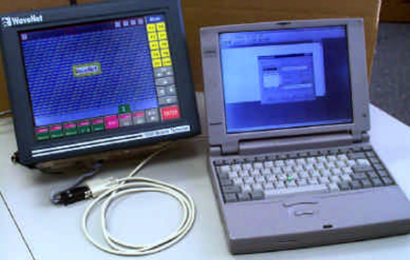
Advanced Topics
5000 Mobile Terminal Product Guide (5000-REV2.21) Chapter 7-68
CONNECTING A CONSOLE DEVICE
A console device, usually a personal computer (PC), can be connected to the MT unit’s Console Port in
order to access the Command Line Interface to the resident software modules (tasks). The Command
Line Interface facilitates the entering of task-based commands. The Console screen facilitates the
viewing of any command responses.
? You can not use a Console device while the touch Console window is enabled. This is due
to the Console Port being disabled whenever the BarCode menu item is activated, as it is
for the Console window display (see previous section).
WaveNet’s WaveTERM console utility emulator is recommended to facilitate Console operations. The
WaveTERM software, and the task object code files for task downloads, are available from WaveNet
for WaveNet certified technical support personnel. This software requires a PC with Microsoft
Windows 3.1 or Windows 95 installed.
A three-wire null modem cable (RX Data, TX Data, GND) is required to connect the PC’s
communications port directly to the MT unit’s Console Port.
The following figure shows the connectivity between the MT unit and a laptop PC operating as a
Console device
Figure 7-1 The Console Setup
The following steps will allow you to display the Command Line Interface prompt (>) required for
entering console commands:
1) Double click the WaveTERM icon to display the WaveTERM terminal window. If DC power
is not turned on at the MT unit, there will be no prompt (>) showing at this step. If DC power
is turned on at the MT unit, there will only be a prompt (>) showing at this step.
2) Turn on, if not already on, the DC power to the MT unit, and then press the console <Enter>
key. The prompt (>) will appear.
3) You may now enter a console command at the prompt (>).
Advanced Topics
5000 Mobile Terminal Product Guide (5000-REV2.21) Chapter 7-69
DOWNLOADING IMAGES TO FLASH MEMORY
Flash memory tasks can be updated by downloading new image files. These files can be downloaded by
using load task commands.
? Using load task commands requires access to the Command Line Interface via a Console
device (see previous section), not via the touch Console window. The Console device has
access to the new task images, whereas the Console window does not.
An image file can be downloaded to one of four possible places in Flash memory:
?? At the start sector of an erased Flash memory.
?? At the next available space starting from low address.
?? At the highest available sector that can hold the image.
?? At a specific address.
The Flash memory is protected against being modified while it is in use. If you attempt to download an
image file to the Flash memory while the Flash memory is in use, the load task command will be
rejected and an alert, “Flash in use!” will be displayed.
To ensure that the Flash memory is not in use, use the command:
>load flash now To restart the MT unit.
Loading the Complete Flash Image
In order to download a complete Flash image (set of tasks), there must be enough free low Flash
memory available. High Flash memory is typically reserved for special tasks such as those involving
character sets.
To monitor and erase the current low Flash memory, use the commands:
>load flash now To restart the MT unit.
>load fp To obtain the first sector address.
>FLSH e[first sector address] To erase contiguous memory beginning at [first
sector address].
? Do not use FLSH E command (with upper case E). This command will erase the high
Flash memory in addition to the low Flash memory.
Use the load fp command again to confirm that enough free memory is available.
To download and activate the complete Flash image, use the commands:
>load lf [filename] To load Flash image with [filename].
>load fir To install and run the Flash image in RAM.
Loading a Task Image at Next Available Space
Advanced Topics
5000 Mobile Terminal Product Guide (5000-REV2.21) Chapter 7-70
This command is primarily used to add a new task . This may be required to add new features to the
system or to provide a custom option.
The load task installs images on sector boundaries. When a new image is downloaded, the first
taskname in the image is checked against the first taskname of all images currently in the Flash
memory. If the two names match, then the old image is overwritten. Otherwise, the new image is
written starting at the first available new sector boundary.
To load a task image at the next available space starting from low address, use the command:
>load flash now To restart the MT unit.
>load lf [filename] To load task image with [filename].
Installing a Task Image into High Memory
High memory is an area in Flash memory which is unaffected by a new (complete) Flash image install
procedure. It is generally reserved for character sets or custom tasks.
To install a task image at the highest available sector that can hold the image, use the commands:
>load flash now To restart the MT unit.
>load lfh [filename] To load task image with [filename] into high memory.
Installing a Task Image at Specific Address
To install a task image at a specific start address, use the commands:
>load flash now To restart the MT unit.
>load lf@[address] [filename] To load task image with [filename] at [address].
If the [address] location already contains a task image, the task image with [filename] will be installed
at the subsequent available sector.
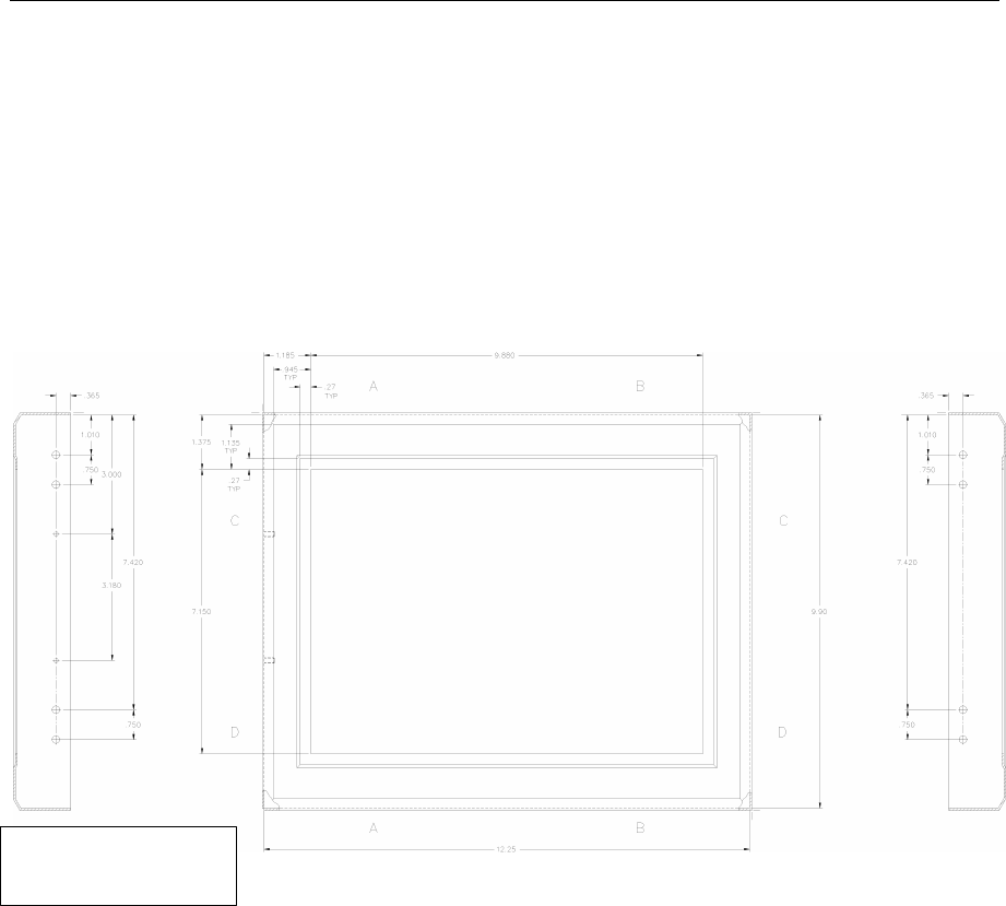
Installation Reference
5000 Mobile Terminal Product Guide (5000-REV2.21) Chapter 8-71
Chapter 8 : Installation Reference
5000 EXTERNAL DIMENSIONS
Figure B-1 Front view of the 5000 Mobile Terminal and dimensions
Width of the
terminal: 3 1/8”
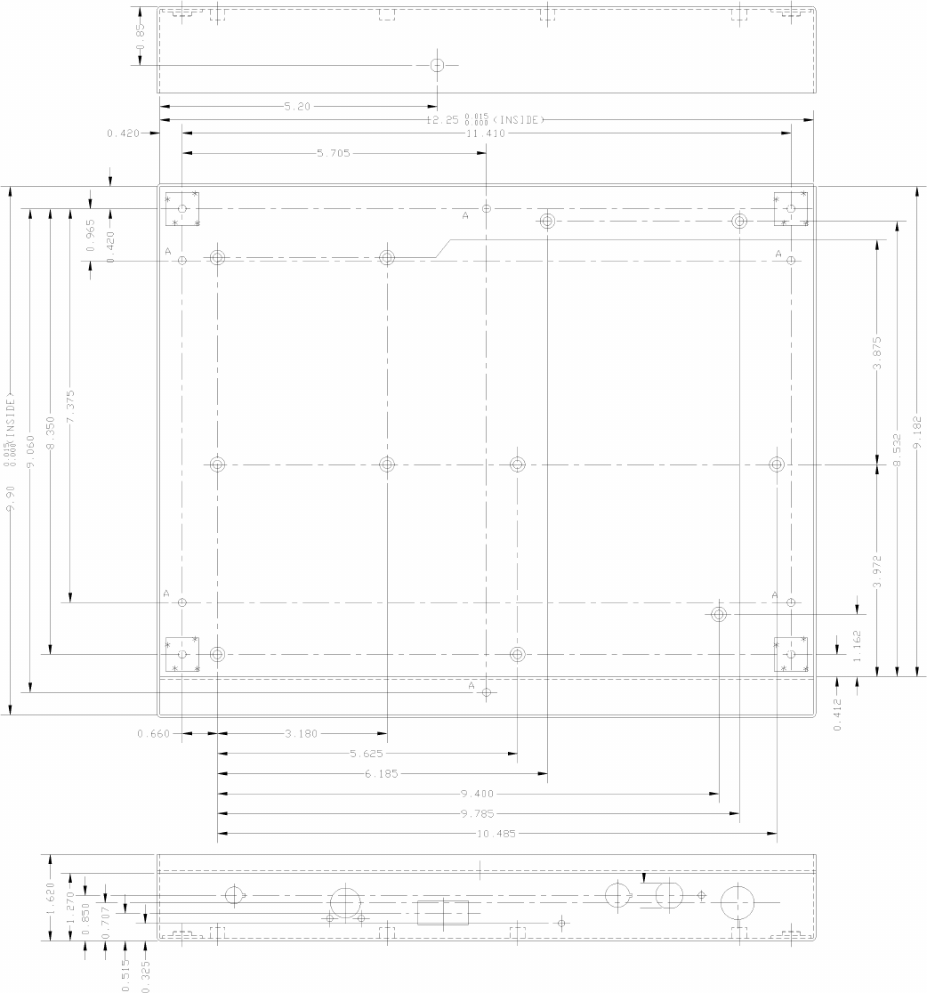
Installation Reference
5000 Mobile Terminal Product Guide (5000-REV2.21) Chapter 8-72
Figure B-2 Rear view of the 5000 Mobile Terminal and dimensions
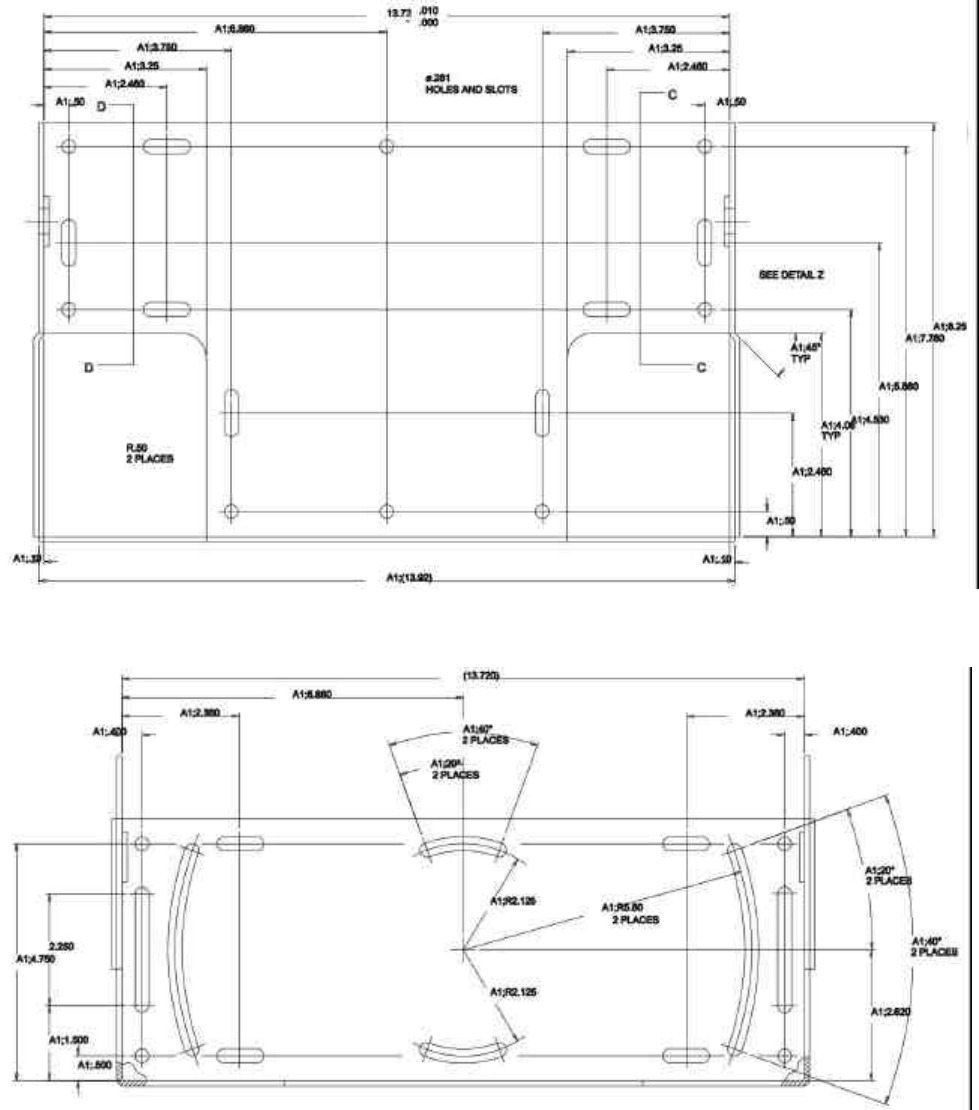
Installation Reference
5000 Mobile Terminal Product Guide (5000-REV2.21) Chapter 8-73
UNIVERSAL TRUCK MOUNTING BRACKET DIMENSIONS
Figure B-3 Rear View of the bracket
Figure B-4 Bottom view of the bracket
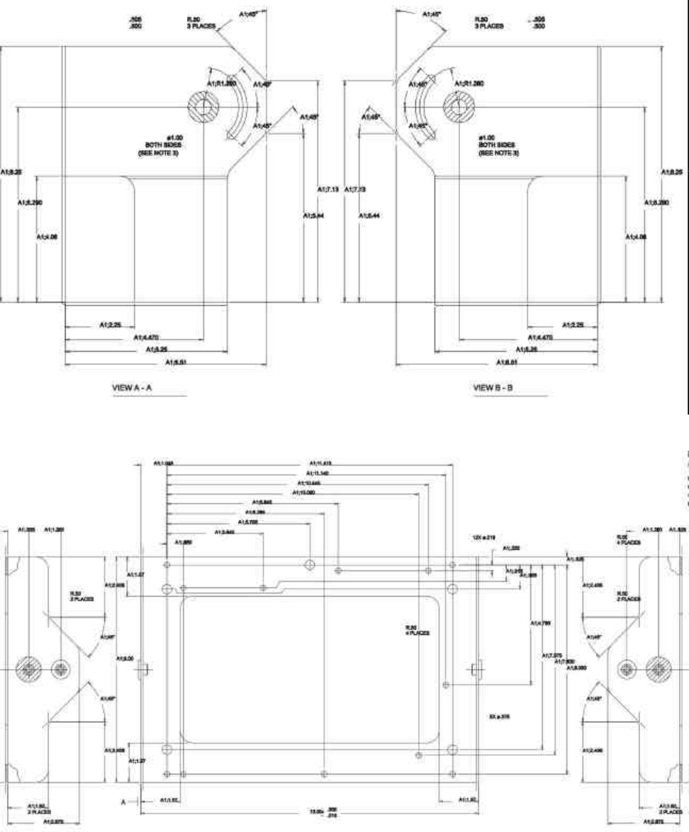
Installation Reference
5000 Mobile Terminal Product Guide (5000-REV2.21) Chapter 8-74
Figure B-5 Sided view of the bracket
Figure B-6 Inner bracket dimensions
Installation Reference
5000 Mobile Terminal Product Guide (5000-REV2.21) Chapter 8-75
Note: All measurements are in inches.
MODEL 5000 MOBILE TERMINAL JUMPER CONFIGURATIONS
SRAM (J2)
J2 Configures SRAM U5 and U6 for 1 Mbyte or 4 Mbyte SRAM
1 - 2 connects HI signal to pin U5-30 and U6-30 (1 Mbyte RAM)
2 - 3 connects A18 to U5-30 and U6-30 (4 Mbyte RAM)
Default 1 - 2
Watch Dog Timer (J3)
J3 Enables watchdog timer
Open - Watchdog timer disabled
Closed - Watchdog timer enabled
Default - Closed
Remote Heater Panel (J4/J11)
J4 Header for remote heater panel (closed if option installed)
J11 Header for remote temperature sensor (closed if option installed)
SRAM Test (J21)
J21 Enables chip select for SRAM unconditionally. For test purposes only
Open - Normal operation
Closed - Test mode
Default - Open
EEPROM (J23)
J23 Configures U4 for 1 Mbyte or 4 Mbyte EPROM
1 - 2 connects HI signal to pin U4-43 (1 Mbyte EPROM)
Installation Reference
5000 Mobile Terminal Product Guide (5000-REV2.21) Chapter 8-76
2 - 3 connects A18 to pin U4-43 (4 Mbyte EPROM)
Default - 1 – 2
SCANNER CONNECTOR
The bar-code interface (scanner connector) used on all WaveNet terminals is as follows:
Terminal Connector :
HIROSE HR10A-10R-10S
Scanner Connector :
HIROSE HR10A-10P-10P
SCANNER CONNECTOR SIGNALS
The following signals are used in the scanner interface (signals marked with * are not software
supported):
WaveNet Pin No. Signal Description Level Direction
1 Undecoded Data (*) TTL Input
2 +5V Power
3 Scanner Trigger (*) TTL Input
4 0V Power
5 Start of Scan (*) TTL Input
6 N/C
7 Scanner Enable (*) TTL Output
8 Serial Receive Data RS-232 Input
9 Scanner Ack (*) TTL Output
10 Serial Transmit Data RS-232 Output
SYMBOL DECODING SCANNER INTERFACE (TYPICAL)
WaveNet Pin No. Signal Description Symbol Signal Name Symbol Wire Color
1 N/C
2 +5V +5V Red
3 N/C
4 0V GND Black
5 N/C
6 N/C
7 N/C
8 Serial Receive Data TXD Yellow
9 N/C
10 N/C

Installation Reference
5000 Mobile Terminal Product Guide (5000-REV2.21) Chapter 8-77
In this connection, the Brown (DTR) wire should be not contacted, and the Purple (CTS) wire should
be looped back to the Blue (CTS) wire.
CONSOLE/SERIAL I/O CONNECTOR
The console connector used to interface to any WaveNet terminal console port is as follows:
Plug :
FUJITSU FCN-230C020-A/E
Shield :
FUJITSU FCN-237R020-G/G
The standard pin-out of the console/serial I/O connector is as follows:
Pin # Name Function
1 +12V 12V Power
2 Spkr Pwr External Speaker/Microphone Power
3 +5V 5V Power
4 +5V 5V Power
5 GND Ground
6 TXD1 Transmit Data 1 (External)
7 RTS1 Request to Send 1 (External)
8 RXD1 Receive Data 1 (External)
9 CTS1 Clear To Send 1 (External)
10 DCD1 Data Carrier Detect 1 (External)
11 TCLK1 Transmit Clock 1 (External)
12 RCLK1 Receive Clock 1 (External)
13 GND Ground
14 SINAD Radio SINAD Out (Radio Test Only)
15 CD Carrier Detect Out (Radio Test Only)
16 RSSI Receive Signal Strength Indicator (Radio Test Only)
17 TXD2 Transmit Data 2 (Console)
18 RXD2 Receive Data 2 (Console)
19 Mic (In) External Microphone Audio In
20 Spkr (Out) External Speaker Audio Out
TYPICAL EXTERNAL CONSOLE & DEVICE CABLE CONNECTIONS
The following shows a simple, typical cable connection for an external RS-232 device (assuming a
DB9F Connector):
Pin # Name Function External Device Pin # Function
5 GND Ground 5 Ground
6 TXD1 Transmit Data 1 (External) 2 RXD
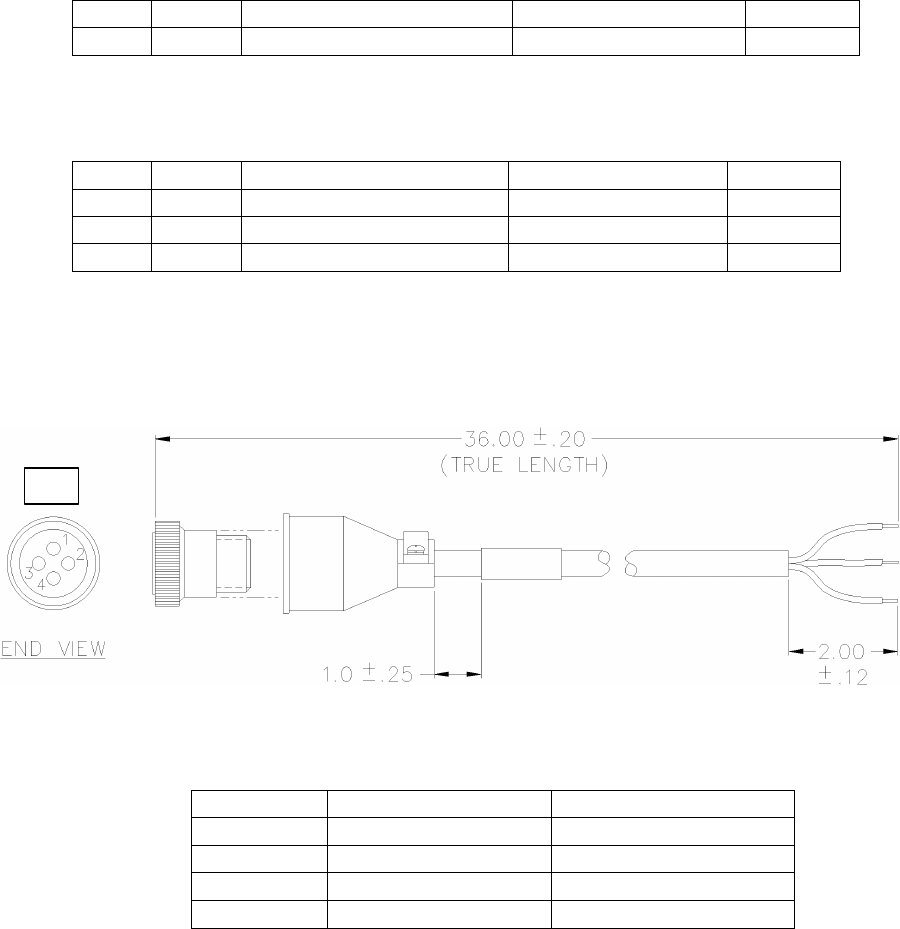
Installation Reference
5000 Mobile Terminal Product Guide (5000-REV2.21) Chapter 8-78
Pin # Name Function External Device Pin # Function
8 RXD1 Receive Data 1 (External) 3 TXD
The following shows a simple, typical cable connection for a Console Cable (assuming a DB9F
Connector):
Pin # Name Function Console Cable Pin # Function
13 GND Ground 5 Ground
17 TXD2 Transmit Data 2 (Console) 2 RXD
18 RXD2 Receive Data 2 (Console) 3 TXD
POWER CONNECTOR AND EXTENSION CABLE
Figure B-7 Power Connector and Cable
P1 Color Signal
1 RED +12V
2 WHITE +24 TO +48V
3 BLACK GROUND
4 WIRE/DRAIN DRAIN
P1
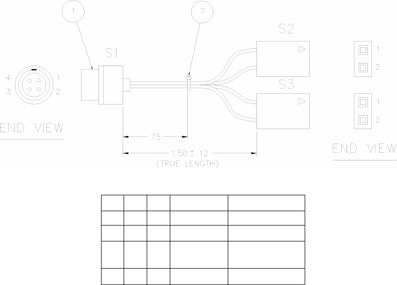
Installation Reference
5000 Mobile Terminal Product Guide (5000-REV2.21) Chapter 8-79
SPEAKER/MIC PORT
S1
S2
S3
COLOR SIGNAL
1 1 BLACK MIC IN
2 2 WHITE AUDIO OUT
3 1 ORANGE
SWITCHED
POWER
4 2 BLACK GROUND
Product Specifications
5000 Mobile Terminal Product Guide (5000-REV2.21) Chapter 9-81
Chapter 9 : Product Specifications
Note : Product specifications subject to change.
PHYSICAL & ENVIRONMENTAL
Enclosure: Sealed NEMA style steel with poly-enamel finish.
Size & Weight: 12.4 (W) x 10.0 (H) x 3.1 (D) in. [31.2 x 25.2 x 7.8 cm], 10.1 lbs.
[4.6 Kg.].
Shock & Vibration: Rated to MIL-STD 810D.
Power: 12 - 60 VDC @ < 3.0 Amp, Surge protection & filtering inc., AC
power Optional with external convertor.
Operating Environment: 0 to 50ºC (14 to 122ºF), Optional -30ºC to 50ºC (-22 to 122ºF) with
optional internal heater. Meets 4 inch per hour ambient rain.
Storage Temperature: -30 to 60ºC (-22 to 122ºF)
Relative Humidity: 5 to 95 % (Non-Condensing)
ARCHITECTURE
Processor: Integrated 32-Bit CISC General Purpose Processor with dedicated
RISC Communications Processor; 8-bit auxiliary microcontroller.
FLASH Memory: 2 MByte (maximum)
RAM: 768 KByte (maximum)
EEPROM: 2 KByte
RADIO TECHNOLOGIES
Narrow Band UHF-FM: 406-512 MHz, 8-Channel Synthesized, 0.1 - 2.0 Watts, 14,400 bps
maximum channel speed.
Spread Spectrum: 902-928 MHz, 7-Channel Synthesized, 122 Kbps maximum channel
speed, direct sequence.
2.4 GHz Aironet 4500/4800 (1& 2 Mbps) 802.11 compliant
DISPLAY/KEYBOARD
Display: Color - 16 colors, 10.4 in. (26.4cm) diagonal, 25 lines by 80
characters, backlit. Mono - 16 grayscale, 10.4 in. (26.4 cm)
diagonal, 25 lines by 80 characters, backlit.

Product Specifications
5000 Mobile Terminal Product Guide (5000-REV2.21) Chapter 9-82
Font Sizes: 8 standard (single byte), ASCII and DEC multi-national character
set;
2 standard (double byte) Chinese and Korean character sets.
Touch Panel: Resistive, High Resolution, coated polyester over glass, surface
durability meets TABER abrasion test ASTM-D-1044, CS-10F
Wheel, 1000g.
Backlit Touch Pad: All touch pad keys programmable with character strings or macro
operations
Pop-up Keypads: Standard keyboard designs for QWERTY Alpha & Alphanumeric,
ABCD Alpha & Alphanumeric, Special Symbols, Punctuation,
Function Keys, VT220, IBM 5250 and IBM3270. User designed
keys can be programmed with any key function, character strings or
macro operations.
EXTERNAL DEVICE INTERFACES
Serial I/O 20 pin locking multipurpose interface connector. Pin outs support
terminal console (can be reassigned as an additional RS232 port);
RS-232 communications (with flow control); diagnostic test points.
Ext. Keyboard PC/AT keyboard interface
Scanner 10 pin locking connector for tethered decoded bar code scanner
Voice I/O 4 pin locking connector for external speaker microphone (UHF-FM
Narrow Band systems only)
DC Power 3 pin locking connector for DC power source to termina

Revision History
5000 Mobile Terminal Product Guide (5000-REV2.21) Chapter 9-83
Chapter 10 : Revision History
Date Revision Description
June 13, 2001 2.22 Update FCC statement. Add “Antenna Location”. See preface.
January 24, 2001 2.21 Addition of Aironet 4800/4500 “air s” and “air a” commands to
Radio Section.
July 14, 2000 2.2 Additional Aironet 4800/4500 radio configuration commands
June 13, 2000 2.1 Aironet 4800/4500 2.4 GHz radio support documentation. Add
in descriptions of Demo Service.
April 5, 1999 2.0 Added product specifications as an appendix, included
mechanical information, antenna specifications and mechanical
installation drawings, cable diagrams. Added 5000 exterior
dimensions, Power connector/cable schematic, Spkr/Mic pin
outs to the installation reference. Reformat for double sided,
eliminate reference to WTN
May 31, 1998 1.0 First Release

Index
5000 Mobile Terminal Product Guide (5000-REV2.21) Index - 84
Index
“
“captive” connection 6-59
<
<Mode> key 5-33
2
2.4 GHz 5-37, 5-39, 5-41, 5-42, 5-44, 6-57, 6-63,
9-88, 9-89
2.4 GHz (Aironet) 5-37, 5-39, 5-41
7
7000 Base Controller 6-53, 6-54, 6-55, 6-56, 6-57
A
About the Current Session 6-53
Aironet 6-57, 6-63
Aironet 2.4 GHz radio system 5-41
Aironet 2.4 GHz Radio System 5-44
AllVersions 5-34, 5-36, 5-37, 5-39
ANSI or DEC compatible host 6-57
ANSI/VT220 compatible computer system 6-58
ASCII 6-49
Assigning Hot Keys to Keyboards 7-70
ASSIGNKEY 5-35, 5-37, 5-38, 5-41
AssignKey menu item 5-41
Auto-Connect 6-59, 6-60, 6-61
Auto-Connect configuration 6-59
Auto-Connect feature 6-59
Auto-Connect list 6-60, 6-61
Auto-Connects 6-59, 6-60, 6-62, 6-63
Auto-Login configuration 6-61
Auto-Login facility 6-61
Auto-Login Services 6-61
B
BarCode 4-30
barcode scanner support 6-56
bi-directional 1-5
Bit Rate 5-38, 5-39
Break/ShowAllKeys 7-67
C
Calibrate 4-29
Capacitive type touch-screens 1-4
Caps Key 7-68
Casc 4-25
CD 3-21
Channel 5-33, 5-34, 5-36, 5-38, 5-40
ChanSelect 5-33, 5-36, 5-38, 5-39
Character Set 6-49
Chinese 6-49
Clone 5-34, 5-36, 5-37, 5-39
CloneParam’s menu item 5-39
cloning 5-34, 5-36, 5-37, 5-39
Combine Keys 7-67
Command Line Interpreter (CLI) 6-56
Communication Settings 6-47
computer systems 1-5, 1-6
configuration 5-33, 5-34, 5-35, 5-36, 5-37, 5-39, 5-
40
configuration security level 4-28
Connecting a Console Device 7-72
Consol 6-57
Console port 1-2
Console Port 1-3
Console session 6-56, 6-57, 6-59
Console window 3-15
Contrast buttons 3-18
Contrast Level 3-18
Convert Caps 7-68
coverage zone 1-6
coverage zones 1-6
current DNS assignments 6-59
current security level number 4-28
custom keyboard 7-65
D
Data Bits 6-48
DC power source 1-1
Debug 5-34, 5-36, 5-37, 5-39
Deleting a Custom Keyboard 7-70
digital radio data communications 1-5
direct TELNET connection 6-63
Display 3-12
Display Settings 6-48
DNS (Dynamic Name Service) 6-58
DNS name 6-59
DNS server functions 6-58
DNS services 6-57
DNS Services 6-58
Downloading Images to Flash Memory 7-73
E
Emulation Setting 6-47
Entering Key Data 7-69
Entering Key Text 7-69
Index
5000 Mobile Terminal Product Guide (5000-REV2.21) Index - 2
ER 3-21
Error 5-35, 5-36, 5-40
Ethernet TCP/IP network 6-57
External bar code scanner 1-6
external console connection 6-57, 6-59
external console port 6-56, 6-57
external DC power 2-9
external RS-232 communications 1-6
F
Font 6-49
Font Map 6-49
function keys 5-41
Function keys 3-13
H
HeaderSize 5-38
holster 1-6
Host ID 6-48
Host ID = 15 6-57
Host Service 6-47
Host Time Out 6-61
Host Time Out configuration 6-61
Hot Key 5-35, 5-37, 5-38
hot key sequences 3-20
I
industrial vehicles 1-6
Installing a Task Image at Specific Address 7-75
Installing a Task Image into High Memory 7-75
interactive multi-session communications 1-6
internal RFID 1-6
K
Key Border 7-68
Key Features 7-68
Key Fonts 7-68
Keyboard Port 1-3
Keyboard/Key Size and Shape 7-66
KeyHide 7-67
keypad 1-6, 5-41
Korean 6-49
L
LCD display 1-6
load fir 7-74
load flash now 7-74
Loading a Task Image at Next Available Space 7-
74
Loading the Complete Flash Image 7-74
local area radio data network 1-5
Local Console Session 6-56, 6-57
Local Prompt 6-60, 6-61
local Telnet capability 6-61
Local Telnet Session 6-57
Local Telnet Sessions 6-57
Location button 3-17
M
MAC layer 5-40
memory 5-34, 5-36, 5-37
Menu Bar 5-33, 5-36, 5-37, 5-41, 5-43
Min/Max button 3-17
mnemonic text 6-58
mobile data devices 1-5
Mobile Device 1-5, 1-6
Mobile Devices 1-5, 1-6
Model 1000 Data Modem 1-7
Model 3000 Portable Terminal 1-6
Model 5000 Mobile Terminal 1-6
MONITOR 5-35, 5-36, 5-37
Monitor menu 5-40
monitoring 5-40
N
Navigation keys 3-13
NET layer 5-40
Network Devices 1-5, 1-6
New Font 7-69
NewVer menu item 5-39
NodeAddress 5-38, 5-39
O
OldVer menu item 5-39
P
Page Caching 6-48
Passwords 4-26
PING test 5-42
PING utility 5-41
pistol grip 1-6
Pop-up Keyboard Settings 6-50
Pop-up keyboard toggles 3-13
Pop-up Keyboards 3-19
pop-up menu 3-18
portable industrial applications 1-7
power ON/OFF 1-2
power ON/OFF switch 2-9
Powering down 2-9
powering up/down 2-9
pre-defined sample graphics 4-26
Presentation Manager 4-23
Presentation Manager window 3-15
Presentation Window Menus 4-23
printer 1-6
process controller 1-6
Index
5000 Mobile Terminal Product Guide (5000-REV2.21) Index - 3
R
radio data communications 1-5, 1-6
radio data coverage 1-5
Radio Gauges 3-21
Radio Manager 5-33
Radio Manager window 3-15
radio statistics 5-35, 5-36, 5-37, 5-40, 5-43
RAM Backup 2-10
Reboot. 5-39
remove hot keys 3-21
remove the current password 4-27
Resistive type touch screens 1-4
Restarting 2-10
Reviewing Keyboards 7-70
RF port 1-2
RF Port 1-3
RF site survey 5-41
route 5-35, 5-37, 5-38, 5-40
RowOffset 7-67
RX 3-21
S
Saving Custom Keyboards 7-69
Saving the Setting 4-31
scaleable 1-5
Scanner Port 1-3
Screen Size 6-50
Scrolling 3-18
Security Options 4-26
Serial I/O Toggle 6-51
Session Cloning 6-51
SESSION layer 5-40
Session Manager windows 3-15
Session window 4-25
Session Window Menus 6-45
Shift Key 7-68
Size button 3-17
T
TCP/IP services 6-57
TELNET application 6-63
TELNET configurations 6-57
Telnet connection 6-57
Telnet Prompt 6-57
TELNET server 6-63
Telnet> 6-57, 6-58, 6-60
Terminal TELNET Server 6-63
TESTS 5-34, 5-36
Tests menu 5-40
Text editor keys 3-13
the Network Devices 1-6
Tile 4-25
Touch Screen Areas 3-11
Touch Screen Calibration 4-28
touch-screen 1-6
touch-sensitive Console window 7-71
TX 3-21
U
unique IP (Internet Protocol) address 6-57
Using a PC Keyboard 7-70
V
Voice Port 1-3
W
waveNet wireless lan 1-5
WaveNet Wireless LAN5-33, 5-35, 5-37, 5-38, 5-
39
window menus password 4-27
Window Switching 3-15
wired terminal 1-6
wireless LAN 6-57