Wavetronix SS105 Traffic Sensor User Manual
Wavetronix, LLC Traffic Sensor
Manual
User Manual
Model: SmartSensorTM 105
10.525 GHz Microwave Traffic Sensor

Wavetronix, LLC SmartSensor 105 User Manual
2
FCC COMPLIANCE
THIS EQUIPMENT COMPLIES WITH PART 15 OF THE FCC RULES. ANY
CHANGES OR MODIFICATIONS NOT EXPRESSLY APPROVED BY THE
MANUFACTURER COULD VOID THE USER’S AUTHORITY TO OPERATE THE
EQUIPMENT.
Proprietary
Copyright Wavetronix, LLC. All rights reserved.
Wavetronix products are covered under U.S. and foreign patents, issued and pending.
Specifications change privileges reserved.
SmartSensorTM is a register trademark of Wavetronix, LLC.
Technical Support and Product Information
www.wavetronix.com
1-800-764-0277
Wavetronix, LLC, Provo, Utah, 84604
Wavetronix, LLC SmartSensor 105 User Manual
3
Contents

Wavetronix, LLC SmartSensor 105 User Manual
4
Unpacking
The smart sensor packaging should include the following items:
1. SmartSensor 105 Detector
2. Mounting Plate
3. (5) Mounting Screws
4. Sensor Cable (Customer Specific Length)
5. User Manual
6. CD with Software
If any of these items are missing record the serial number located on the side of
the sensor and contact the Wavetronix Support at ??. Additional products may
be purchased through your distributor, and software and firmware may be
downloaded using you Wavetronix customer ID number for free at
www.wavetronix.com .
Unit Identification

Wavetronix, LLC SmartSensor 105 User Manual
5
Installing
Physical installation of the SmartSensor
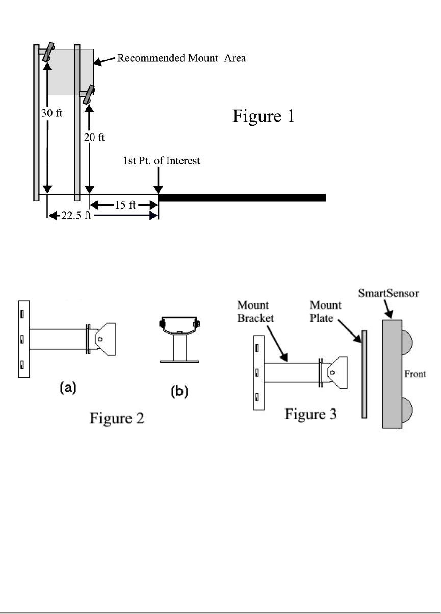
• Choose a location for the sensor to be mounted. The sensor can be mounted on a
vertical or horizontal placed pole or on a flat vertical surface (i.e. wall, billboard,
etc.). It is recommended that the mounting location be a distance 15-22.5 ft from
the nearest point of interest and mounted 20-30 ft above road level as illustrated in
figure 1.
• There are 2 available brackets to choose from. Secure the mounting bracket to the
selected surface facing the desired detection area.
1) Adjustable pole mounting bracket. This bracket can be used on
vertical or horizontal poles and requires three bands to secure it to a
pole. The bracket has 360° of vertical/horizontal adjustability and 70°
of tilt adjustability (figure 2a).
2) Adjustable flat mounting bracket. This bracket can be used on flat
vertical surfaces and requires 4 bolts to secure it to the surface. The
bracket has 70° of tilt adjustability (figure 2b).
• Secure the mounting plate to the bracket with 2 tapered screws (figure 3).
• Secure the SmartSensor to the mounting plate or bracket with five ¼ - 20 screws
(figure 3).
• Aim the front of sensor at the center of the detection area (figure 1 & 3).
• Connect the power/communication cable to the SmartSensor and attach the
modem antenna if applicable.
Sensor cable is must be at least 2 m long or the FCC license is void!
Wavetronix, LLC SmartSensor 105 User Manual
6
Software Configuration
Tracking Installations
Trouble Shooting

Wavetronix, LLC SmartSensor 105 User Manual
7
Upgrading Firmware
Specifications
Warranty

Wavetronix, LLC SmartSensor 105 User Manual
8
Notes
Wavetronix Customer ID Number: _____________________
Serial Number: _____________________________________
Date Installed: __________ Installation Site: ______
Wavetronix, LLC SmartSensor 105 User Manual
9
Part Number: XXXXXXXXX BARCODE