Wayne Dalton ID372R2 GARAGE DOOR OPENER W/ RF LIGHT KIT/ TRANSCEIVER User Manual 297368
Wayne Dalton Corporation GARAGE DOOR OPENER W/ RF LIGHT KIT/ TRANSCEIVER 297368
MANUAL

5015 B.U. Bowman Drive Buford, GA 30518 USA Voice: 770-831-8048 Fax: 770-831-8598
FCC Part 15
433.92 MHz Transmitter Certification
& 372 MHz Receiver Declaration of Conformity
Test Report
FCC ID: KJ8-ID372R2
FCC Rule Part: 15.231
ACS Report Number: 03-0197-15C231
Manufacturer: Wayne-Dalton Corporation
Equipment Type: RF Controlled Garage Door Opener
Model: Operator 40XR (Torsion idriveTM)
Model Variants: 3660-372, 3661-372, 3662-372, 3663-372, 3740-372,
3760-372, 3761-372, 3762-372
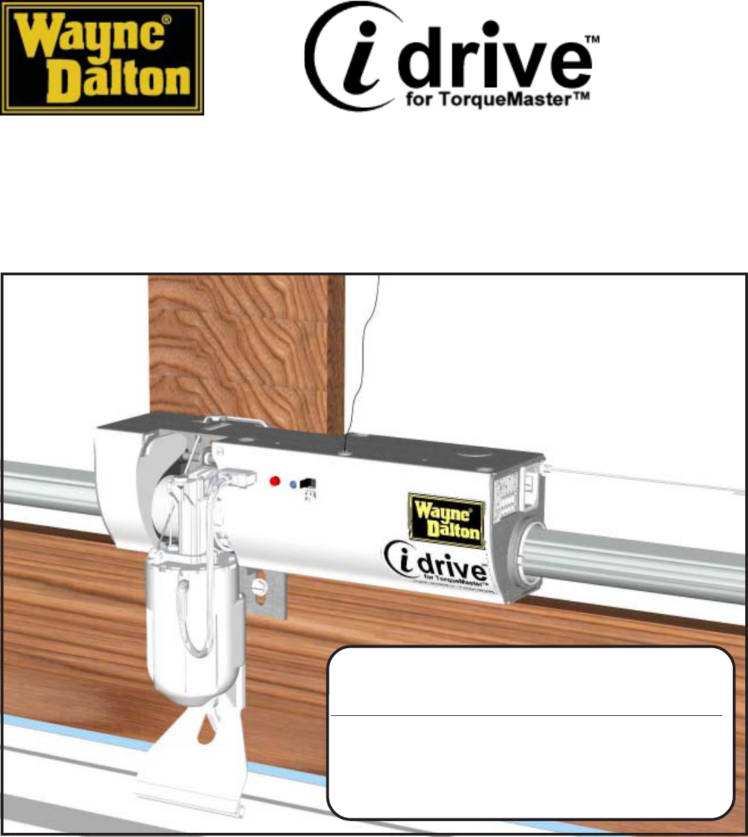
Installation and Operators Guide
Wayne-Dalton Corp.
P.O. Box 67 Mt. Hope, OH 44660
(888) 827-3667
www.wayne-dalton.com Models: 3660-372 / 3661-372/3662-372/3760-372
Covered under one or more of the following U.S. patents: 5,929,580/5,931,212/5,419,010/6,561,255/6,561,256/
6,401,792/6,326,751/6,326,754/6,325,134/6,263,947/6,164,014/6,078,249/D157,139/D157,140/D466,141/D413,867/
D413,579/D421,031/D472,568/D472,910/6,605,910 European Patent: 0925417
other U.S. and foreign patents pending
© Copyright 2004 Wayne-Dalton Corp. New
Part No.??????
Important Notice!
Read the enclosed instructions carefully before installing/operating this garage
door opener. Pay close attention to all warning labels and notes. This manual
should be attached to the wall in close proximity to the garage door opener.
1/19/04C
USE OF THIS MANUAL
WHEN INSTALLING A NEW DOOR WITH THE OPENER:
Complete the door installation before proceeding with
these instructions. (See “INSTALLATION NOTICE” on
Page 2 of this manual.)
PRELIMINARY
PRELIMINARY
PRELIMINARY
PRELIMINARY
PRELIMINARY
1/19/04
1/19/04
1/19/04
1/19/04
1/19/04
Installation Instructions and Owner’s Manual
Table of Contents
INSTALLATION NOTICE:
If installing this idrive™ opener on a door currently
installed with a TorqueMaster™ counterbalance system, start installation on page 6. If
Installing this idrive™ opener as part of a new door installation, complete the door
installation first (using instructions supplied with the door), then proceed to Step: 16 on
page 16, of this manual, for the remaining opener installation procedures.
System Requirements
WARNING
To reduce the risk of injury, use this opener only with the following door systems:
After installation is complete, fasten this manual near garage door. Perform monthly
maintenance (see Maintenance section page 36) and periodic checks, as
recommended.
FCC and IC Statement
FCC Regulatory Information:
This device complies with Part 15 of the FCC Rules. Operation is subject to the following two
conditions: (1) this device may not cause harmful interference, and (2) this device must accept any
interference received, including interference that may cause undesired operation.
IC Regulatory Information:
Operation is subject to the following two conditions: (1) this device may not cause interference, and
(2) this device must accept any interference, including interference that may cause undesired
operation of the device.
NOTLAD-ENYAW LEDOMROOD NOTLAD-ENYAW METSYSGNIRPS )SUIDAR(KCART CIRTCELEOTOHP SROSNESYETFAS DAEHWOL TIKMOOR
SEI
RES0009 ™retsaMeuqroT"51,"41,"21,"01DERIUQERTON TON DERIUQER
SEIRES0009 ™retsaMeuqroTMOORDAEHWOL"6DERIUQERTON 388203N/P D'QER
SEIRES0008 ™retsaMeuqroT"51,"41,"21,"01 ro811252s'N/P 476103 DERIUQER
TON DERIUQER
SEIRES0008 ™re
tsaMeuqroTMOORDAEHWOL"6 ro811252s'N/P 476103 DERIUQER
388203N/P D'QER
Important Safety Instructions 3.
Package Contents 4.
Tools Needed 5.
Available Accessories 5.
Retro-fit Installation 6.-9.
idrive™ Installation 10. - 16.
Pre-Operation Installation 16. - 31.
Operation 32. - 35.
Maintenance 35.
Drill Template 36.
Troubleshooting 37. - 38.
Warranty 39.
Customer Service Number 40.
2
3
IMPORTANT SAFETY INSTRUCTIONS FOR
INSTALLATION AND USE
IMPORTANT SAFETY INSTRUCTIONS FOR
INSTALLATION AND USE
READ AND FOLLOW ALL
INSTALLATION INSTRUCTIONS.
Do not connect the opener to a
power source until instructed to do
so.
Where possible, install the opener
seven feet or more above the floor.
Mount emergency release six feet
above the floor.
Locate the wall station: (a) within
sight of door, (b) at a minimum
height of five feet, so small children
cannot reach it, and (c) away from
all moving parts of the door.
After installing the opener, the door
must reverse when it contacts a 1-
1/2” high object (or 2 x 4 board laid
flat) on the floor.
WARNING: INCORRECT
INSTALLATION CAN LEAD
TO SEVERE OR FATAL
INJURY. FOLLOW
INSTRUCTIONS.
WARNING: IT IS VITAL FOR
THE SAFETY OF PERSONS
TO FOLLOW ALL
INSTRUCTIONS. SAVE
THESE INSTRUCTIONS.
Install the entrapment warning label
next to the wall station in a
prominent location. Install the
emergency release marking on or
next to the emergency disconnect.
Remove all ropes and remove or
make inoperative all locks
connected to the garage door before
installing the opener.
Do not wear rings, watches or loose
clothing when installing or servicing
a garage door system.
Install only on a properly balanced
garage door. An improperly
balanced door could cause severe
injury. Have a qualified service
person make repairs to cables,
spring assemblies, and other
hardware before installing the
opener.
Installation and wiring must comply
with local building and electrical
codes. Connect power cord to a
properly grounded outlet. Do not
remove the ground pin from power
cord.
NOTE: This equipment has been tested and found to comply with limits for a Class B digital device,
pursuant to Part 15 of FCC Rules. These limits are designed to provide reasonable protection against
harmful interference in a residential installation. This equipment generates, uses and can radiate radio
frequency energy and, if not installed and used in accordance with these instruction, may cause harmful
interference to radio communication; however, there is no guarantee that interference will not occur in a
particular installation. If this equipment does cause harmful interference to radio or television reception,
which can be determined by turning equipment off and on, user is encouraged to try to correct interference
by one or more of the following measures: Reorient or relocate receiving antenna. Increase separation
between equipment and receiver. Connect equipment into an outlet on a circuit different from that which
receiver is connected. Consult your dealer or/and experienced radio/television technician for help.
WARNING: Changes or modifications to this unit not expressly approved by party responsible for
compliance could void user’s authority to operate this equipment.
Wear safety glasses for eye
protection when installing or
servicing the opener or door.
4
????? Screw (2)
(for 7-function wall-station)
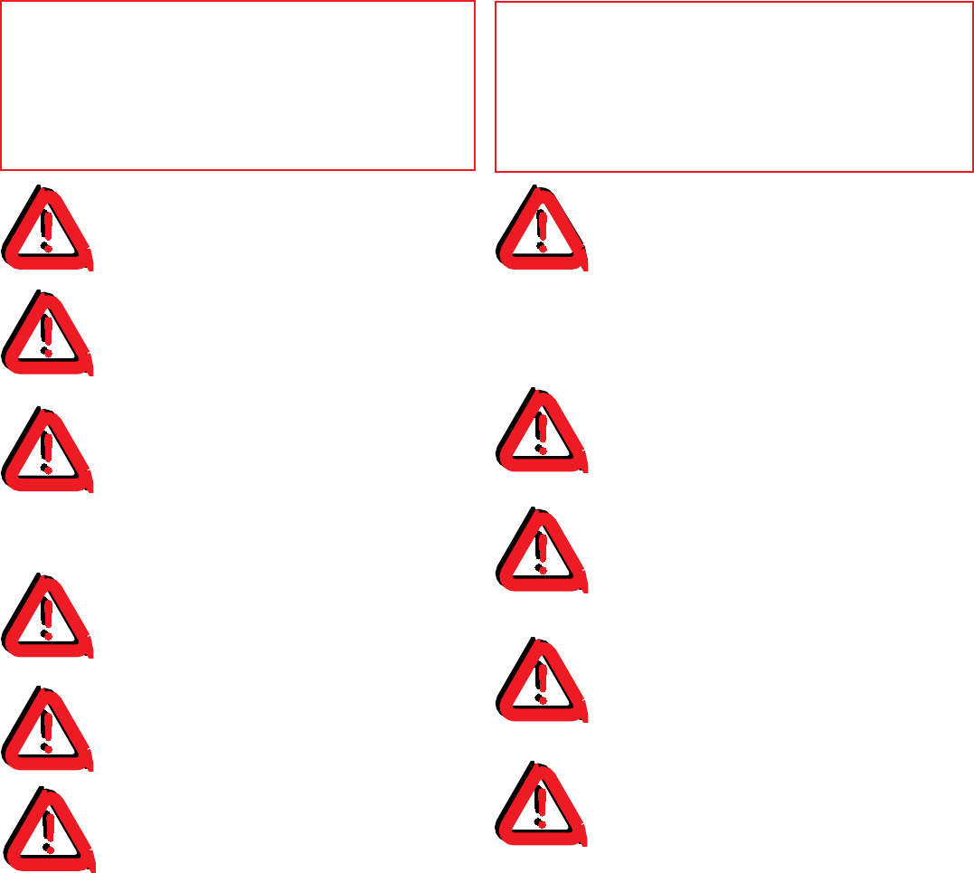
6’ Power Cord (1)
Three-button
Transmitter (2)
Entrapment Label
Wall Station Assembly
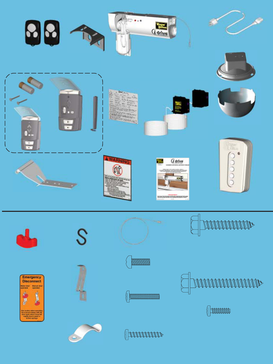
Disconnect
Handle (1)
Handle Bracket (1)
“S” Hook (1) Disconnect Cable (1)
Emergency
Disconnect Label (1)
1/4 x 2” Hex Head Lag Screws (2)
#6-20 x 1/2” Phillips Pan
Head PL Screw (1)
(for disconnect handle)
#6 x 7/8” Phillips Pan
Head Screws (4)
Cable Clips (4)
Lock Arm Assembly
Opener
Support
Bracket
1/4 x 1-1/2” Hex Head Lag Screws (4)
#6-32 x 3/4” Phillips
Pan Head Screw (1)
(For Light Fixture)
M5 x .8 x 12 Phillips
Pan Head Screw (1)
(For Lock Arm)
Package Contents:
Hardware Kit:
Owners Manual
Light Fixture Assembly
w/ Screw & Diffuser???
Wall Station
Reference Label Photoelectric Safety Sensors
W/Hardware(Model 3662-372 only)
5 Button Wireless Keyless Entry
(KEP3) W/ Hardware
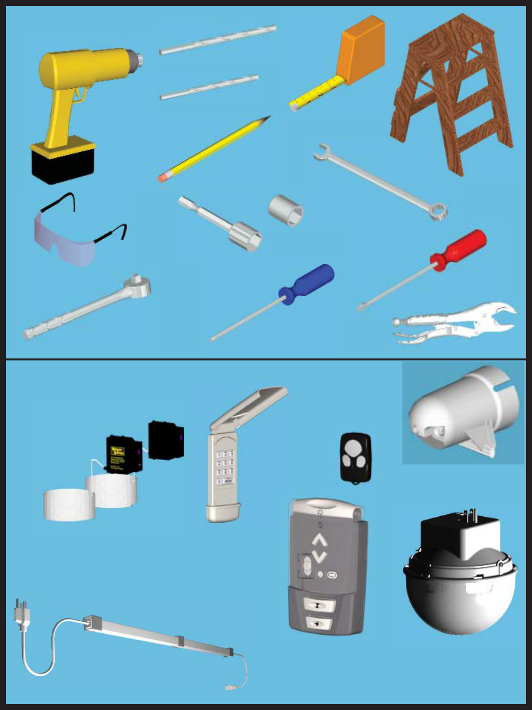
Tools Needed:
Deluxe Wireless Light Kit
Model no: 3951-ULDRE
Part no: 311122
5
Martec Safety Sensor
Model no: 3965
Part no: 301674
Power Drill
Safety Glasses
Tape Measure
Step Ladder
7/16” Wrench
Phillips Head
Screwdriver
7/16” Socket Driver
3/32” Drill Bit
7/16” Socket
Pencil
Flat Head
Screwdriver
3-Button Mini RF
Transmitter
Model no: 3973
Part no: 302083
Keyless Entry RF
Transmitter
Model no: KEP2
Part no: 302078
1/8” Drill Bit
Ratchet
Locking Pliers
Low Headroom Kit
Part no: 302883
Power Cord Extender
Model no: 3960M, Part no: 302616
Available Accessories:
Multi-Function Wall-station
Transmitter
Model no: 3977
Part no: 311365
idrive™ Retro-fit Installation
6
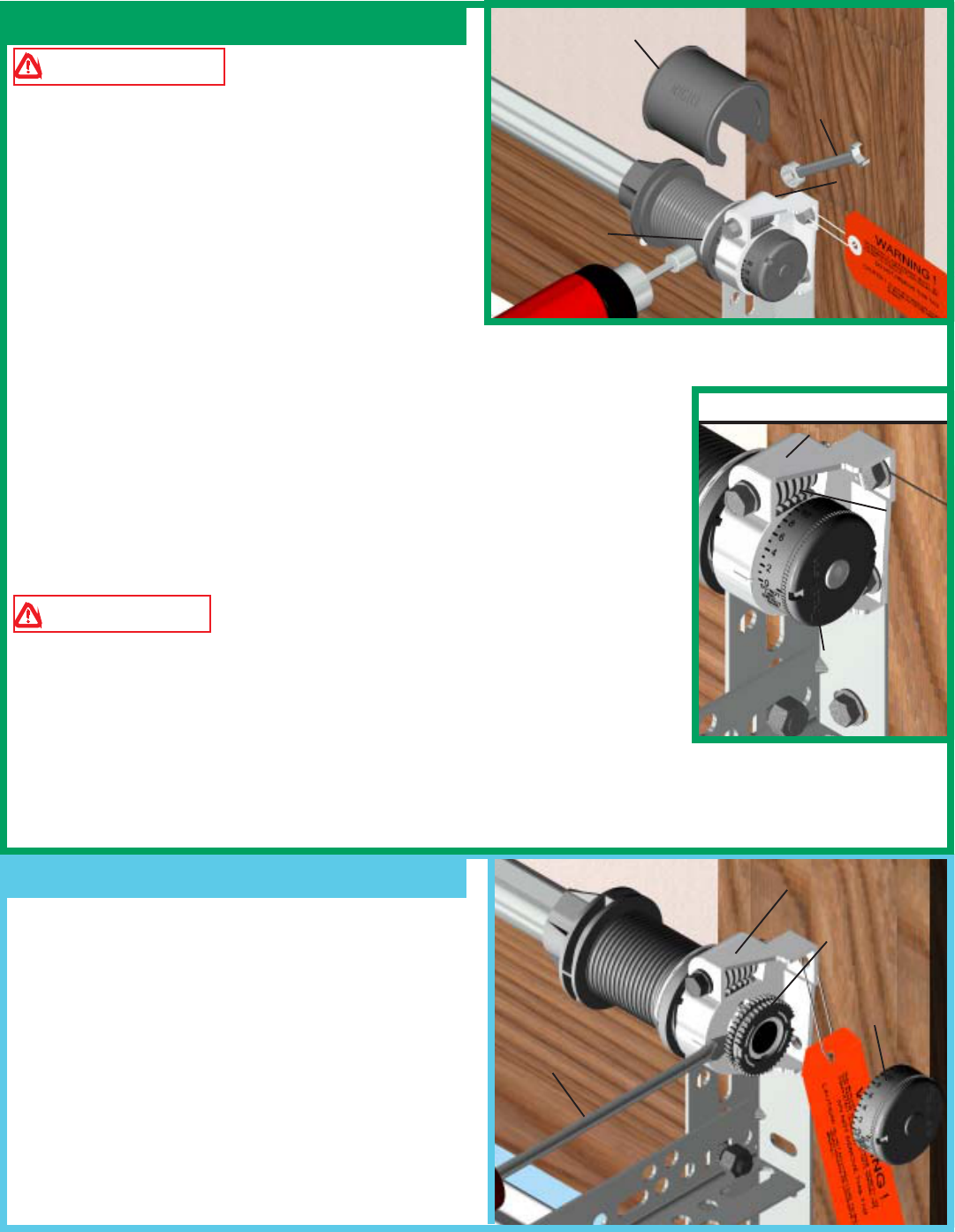
Step 1: Spring Tension Removal
Step 2: Right Hand Counter Removal
WARNING COUNTERBALANCE
SPRING TENSION MUST BE RELIEVED BEFORE
REMOVING ANY HARDWARE. A POWERFUL
SPRING RELEASING ITS ENERGY SUDDENLY
CAN CAUSE SEVERE, EVEN FATAL INJURY.
Remove drum wraps from cable drums (if installed).
Using a 7/16” wrench, loosen lock nut on the back of
the end bracket. Using an electric drill (high torque/
gear reduced to 1300 RPM preferred), with a 7/16”
hex head driver, unwind the right hand winding bolt counter clockwise until
the counter shows zero. If the door has two springs*, repeat this process for the
left hand side.
*NOTE: A door with only one spring will not have a counter assembly on the
left hand side.
NOTE: Spring(s) is/are fully unwound when counterbalance cables have no
tension.
WARNING DO NOT USE AN IMPACT GUN TO UNWIND THE
SPRINGS!
NOTE: It is recommended that cable drums and end bracket assemblies get
updated to current designs for optimal performance. Current end brackets are
made of metal instead of plastic, and counter cover and worm gears are made of
grey plastic, instead of black and white plastic. If new parts are required, contact
Wayne-Dalton Customer Service.
REMOVE THE COUNTER COVER. SLIDE A FLAT
HEAD SCREWDRIVER BETWEEN THE END BRACKET
AND THE COUNTER GEAR. GENTLY PRY THE
COUNTER GEAR AWAY FROM THE END BRACKET.
IF THE DOOR HAS TWO SPRINGS, REPEAT THIS
PROCESS FOR THE OPPOSITE SIDE.
7/16” WRENCH
LOOSEN
LOCKNUT
END BRACKET
COUNTER
GEAR
COUNTER
COVER
SCREW
DRIVER
END BRACKETS
(METAL)
COUNTER COVER
(GRAY)
DRILL
COUNTER
BALANCE
CABLE
DRUM WRAP
WORM
GEAR
CURRENT HARDWARE
7
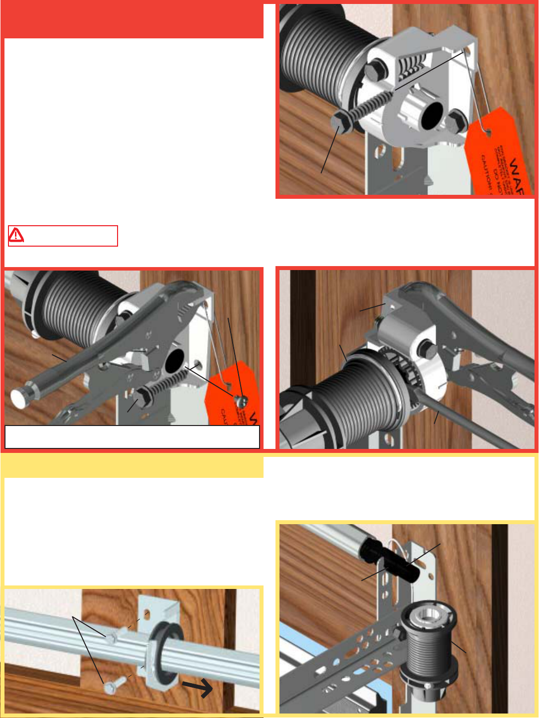
Step 3: Right Hand End Bracket
Removal
Step 4: Drum/Centerbracket Removal
DRUM
To remove the end brackets, follow the steps below
starting with the right hand end bracket first:
1. Remove the upper lag screw from the end bracket.
2. Attach a pair of locking pliers to the upper portion
of the end bracket and hold the end bracket steady while
removing the lower lag screw and the phillips head
screw. Discard phillips head screw.
3. Holding the end bracket with the locking pliers,
carefully pry the end bracket from the drum with a flat
head screwdriver. Repeat for left hand end bracket.
WARNING
THE WINDING SHAFT MAY ROTATE WHEN REMOVING THE END BRACKET
AND GEAR.
1.
2. 3.
REMOVING THE LOWER LAG SCREW AND PHILLIPS
HEAD SCREW (IF EQUIPPED).
WINDING
SHAFT
Remove the two 1/4” lag screws from the center bracket. Slide bracket to the right side of the torque tube. Lift
the right side of the torque tube up and slide the cable drum and center bracket off the end of the torque tube.
Drape the drum over the flag angle by the counterbalance cable and realign the groove in the winding shaft with
the round notch in the flag angle. Once aligned, lower
the winding shaft and torque tube onto the flag angle.
Repeat cable drum removal for left side.
REMOVE 1/4” LAG
SCREWS
SLIDE CENTER BRACKET TO THE RIGHT
ROUND NOTCH
IN FLAGANGLE
UPPER LAG SCREW
LOWER LAG SCREW
REMOVE
PHILLIPS
HEAD TAP
SCREW END
BRACKET
DRUM
LOCKING
PLIERS
FLAT HEAD
SCREW DRIVER
8
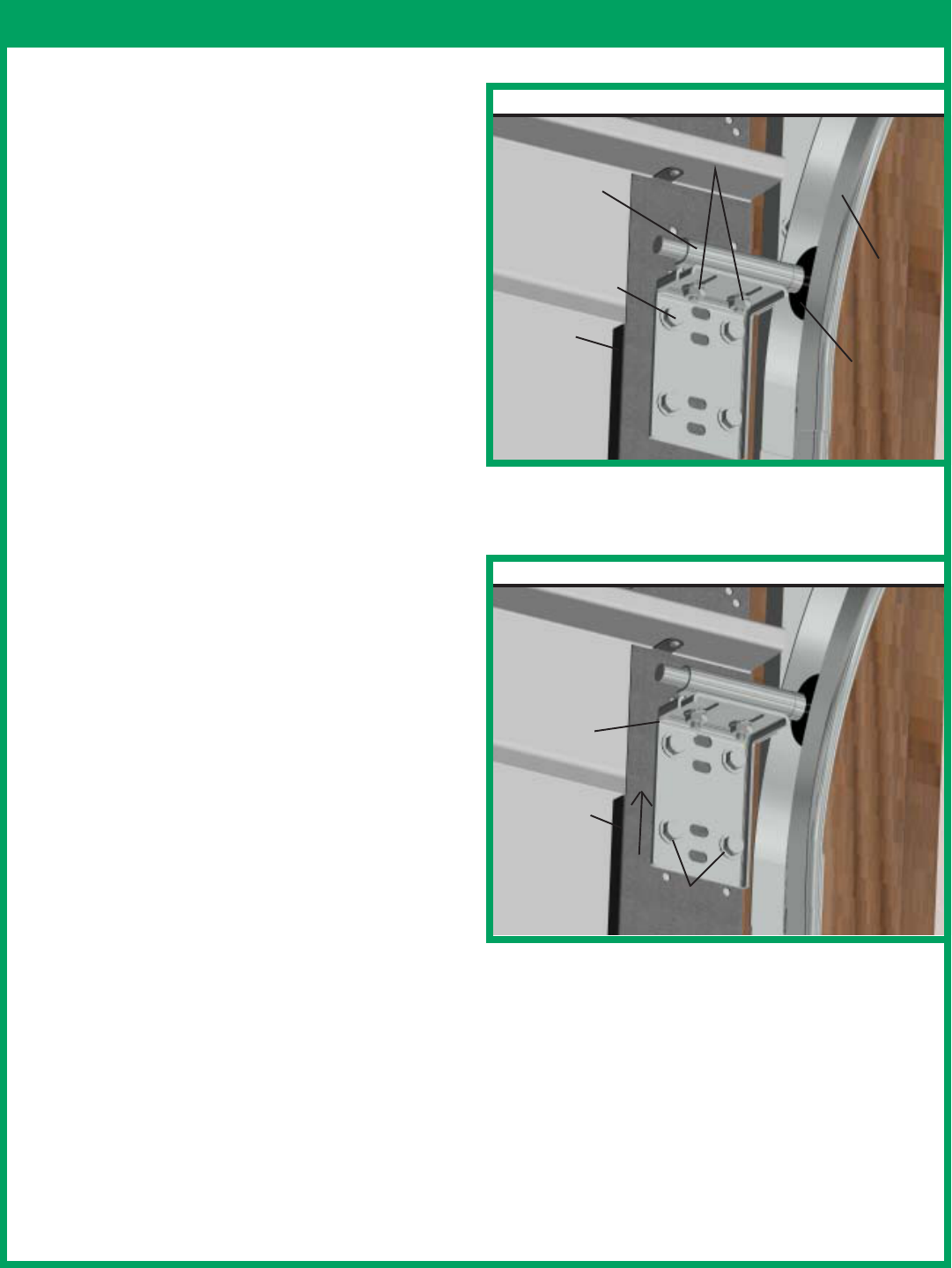
Step 5: 9100 Foamcore™ Top Bracket Re-Installation (If necessary)
If installing an idrive™ opener on a 9100 Foamcore™
door that has already been installed, the top bracket
and roller location will have to be adjusted for the
opener to work properly.
NOTE: The 9100 Foamcore™ doors have a painted
steel face, foam insulation and white paper backing.
If your door does not match this description you may
skip this step.
CAUTION: To avoid the top panel from falling,
complete re-installation on one side before beginning
the other.
Loosen the (2) 1/4-20 nuts from the slider bracket.
Remove the (4) 1/4-14 x 5/8” self-tapping screws from
the top bracket. Raise the top bracket to align the
bottom slots with the second set of holes in the end
cap. Reattach top bracket to the end cap with the (4)
1/4-14 x 5/8” self-tapping screws. Realign the top roller
in the horizontal track by moving the slider bracket
out to force the door section against the weather seal.
Tighten (2) 1/4-20 nuts. Repeat for the opposite side.
(4) 1/4-14 X 5/8”
UNDERCUT
SELF-TAPPING
SCREWS
TOP
BRACKET
TOP
BRACKET
SLIDER
BRACKET
TOP
ROLLER
HORIZONTAL
TRACK
WHITE
PAPER
BACKING
(2) 1/4-20 CARRIAGE
BOLTS AND NUTS
BOTTOM SLOTS ALIGNED WITH
2ND SET OF HOLES
CURRENT
MODIFIED FOR idrive™
END CAP
END CAP
9
Step 6: 8000/8100/8200 Track Adjustment
(if necessary)
If installing an idrive™ opener on a 8000/8100/8200 door, the
top roller location and track height will have to be modified for
the opener to work properly. Perform the following steps.
In the door jamb, fasten a nail between the door and the track
and bend the nail over the section to hold in place. Important
refer to step 1-2 on pg. 6, before continuing to the next step.
Remove the lag screws from the flag angle and each jamb
bracket. Using a 7/16” wrench, loosen the flange nut on the top
bracket slider. Place a mark 1” up from one of the tops of one of
the jamb brackets. Raise the track up and align the jamb bracket
with this line. With the track relocated, reattach the flagangle,
end bracket, and jamb brackets to the header and/or door jamb.
Remove bolt securing back of horizontal track to the perforated
angle and re-level the horizontal track with new 1”(25mm) raised
location. Reattach the horizontal track to the perforated angle
with the same bolt and nut (refer to bottom right illustration).
Remove the (3) self-tapping screws from the top bracket.
Relocate the top hole of the top bracket with the #2 hole in the
end cap and reattach the top bracket to the end cap with the
same three screws. ( It may be required to relocate the top strut
(if installed) to correctly place the top bracket in it new location.)
Once secure, realign the top roller in the track by moving bracket
out until door section is straight up and down. Retighten the
flange nut. Repeat for opposite side.
1”(25mm)
CURRENT MODIFIED FOR idrive™
1” (25mm)
REMOVE LAG
SCREWS
NAIL
NAIL
NAIL
NAIL
JAMB
BRACKET
JAMB
BRACKET
FLAG
ANGLE
LOOSEN
NUT
DO NOT REMOVE TORQUEMASTER
FLANGE
NUT
#2 HOLE
TOP
STRUT
SELF-
TAPPING
SCREWS
TOP
BRACKET TOP
STRUT HORIZONTAL
TRACK
PERFORATED
ANGLES
END CAP
TOP
BRACKET
END CAP
DOOR
JAMB
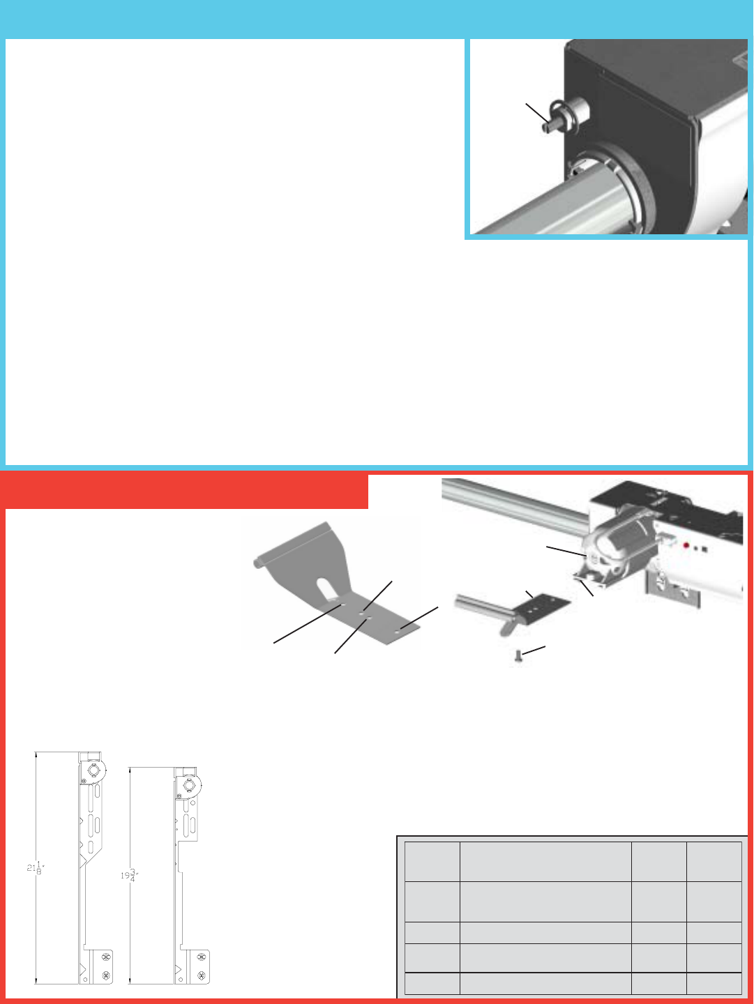
Check the location of the label on the torque tube. See *NOTE
3 below if located on right hand side, otherwise proceed with
the following instructions.
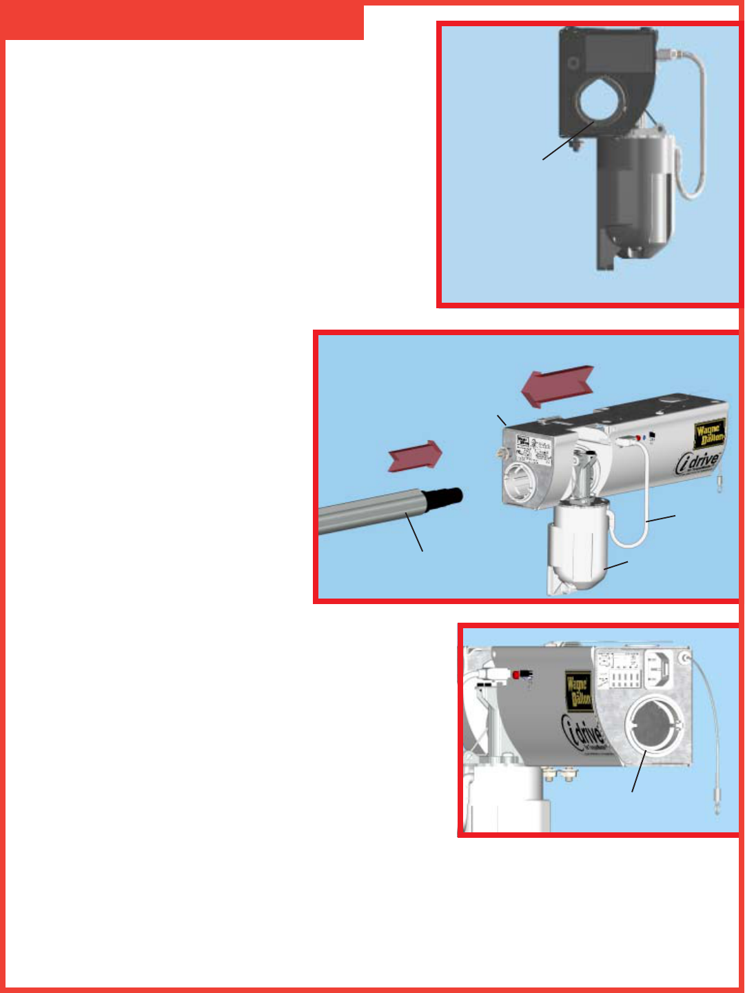
Lay the torque tube on the floor (inside garage) in front of the
door with the labeled end to the left. NOTE: Opener will not
slide over a torque tube label. Attempting to slide opener over
the left end of the torque tube can damage the internal electronics.
IMPORTANT! Right and left hand are always determined from
inside the garage looking out.
NOTE 1: Hold opener by the main body. Do NOT hold by the
motor.
Look into the opener’s left side to ensure the
left hand bearing and the internal (black)
sleeve are aligned with the torque tube
profile. Once aligned, slide the opener onto
the right hand end of the torque tube. As the
right end of the torque tube enters the internal
(black) sleeve, rotate the opener back and
forth slightly to help aid alignment.
NOTE 2: Do not force the opener onto the
torque tube if misalignment occurs.
Continue sliding the opener onto the torque
tube. Align the right hand bearing with the
torque tube and slide the opener completely onto the torque tube
until the torque tube exits the opener right hand bearing. Continue
sliding the opener to the center of the torque tube. Plug the motor
power cord into the opener.
*NOTE 3: IF YOUR TORQUE TUBE HAS THE LABEL
LOCATED ON THE RIGHT SIDE, DOCUMENT THE
INFORMATION ON THE LABEL, THEN REMOVE IT
COMPLETELY USING AN ADHESIVE REMOVER OR
MINERAL SPIRITS.
Step 5: Assembling Opener
10
RIGHT HAND BEARING
TORQUE TUBE AND
BEARING PROFILES
ALIGNED
TORQUE TUBE
(RIGHT SIDE)
OPENER
MOTOR
POWER
CORD
11
Shake the torque tube gently to extend the winding
shafts out about 5" on each side. For single spring
applications, there will be no left hand spring in the
torque tube.
Lift the torque tube and rest on top of flagangles. Orient
torque tube so that back of opener is flat against header/
spring pad.
Cable drums and torque tube are cam shaped to fit
together only one way. To install the cable drum, slide
the drum over the winding shaft until the drum seats
against the torque tube. The winding shaft must extend
past the drum far enough to expose the splines and the
groove. Align the winding shaft groove with the round
notch in the flagangle. Repeat for opposite side for
double spring applications.
For single spring applications, insert the loose winding
shaft into the left hand drum prior to sliding the drum
over the torque tube.
NOTE: On single spring applications, take care in
handling the loose winding shaft (left side) so that it
does not slide back into the torque tube.
OPENER
SPRING
PAD
HEADER
Step 6: Drum Installation DRUM
WINDING
SHAFT
TORQUE
TUBE
Step 7: Drive Gear Installation
LEFT HAND
DRUM
LOOSE WINDING
SHAFT(SINGLE SPRING
APPLICATION)
TORQUE TUBE
Beginning with the right hand side, lubricate entire
circumference of the drive gear with new light weight
oil (not provided). Slide the drive gear onto the winding
splines until it touches the flagangles.
NOTE: No drive gear is required for the left side on
single spring applications.
DRUM
WINDING
SHAFT
GROOVE
ROUND
NOTCH
COUNTERBALANCE
CABLE
OIL
WINDING
SHAFT
FLAGANGLE
SPLINES
DRIVE
GEAR
DRIVE
GEAR
DRUM
FLAGANGLE
12
Step 9: Counter Installation
IMPORTANT! Warning tags must be securely
attached to both end brackets.
NOTE: Older end brackets will not have a hole needed
for the opener’s emergency disconnect cable. If the
right hand end bracket does not have a hole for the
disconnect cable, drill a 3/32” (3mm) hole as shown
prior to installing the end bracket.
Step 8: End Bracket Installation
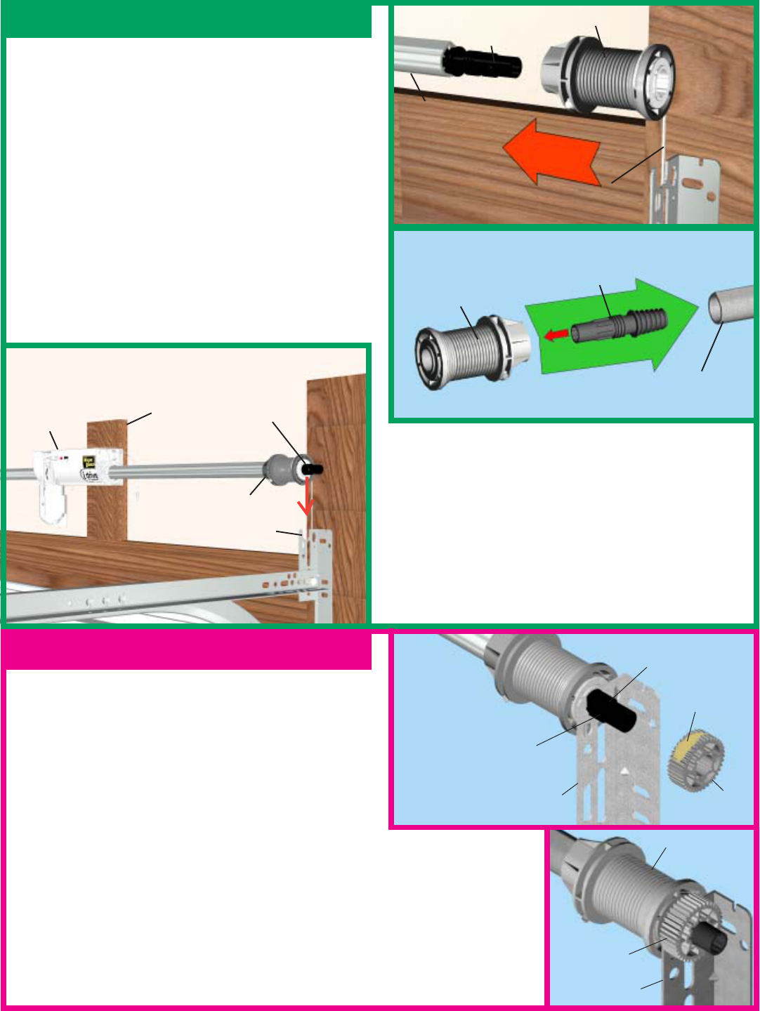
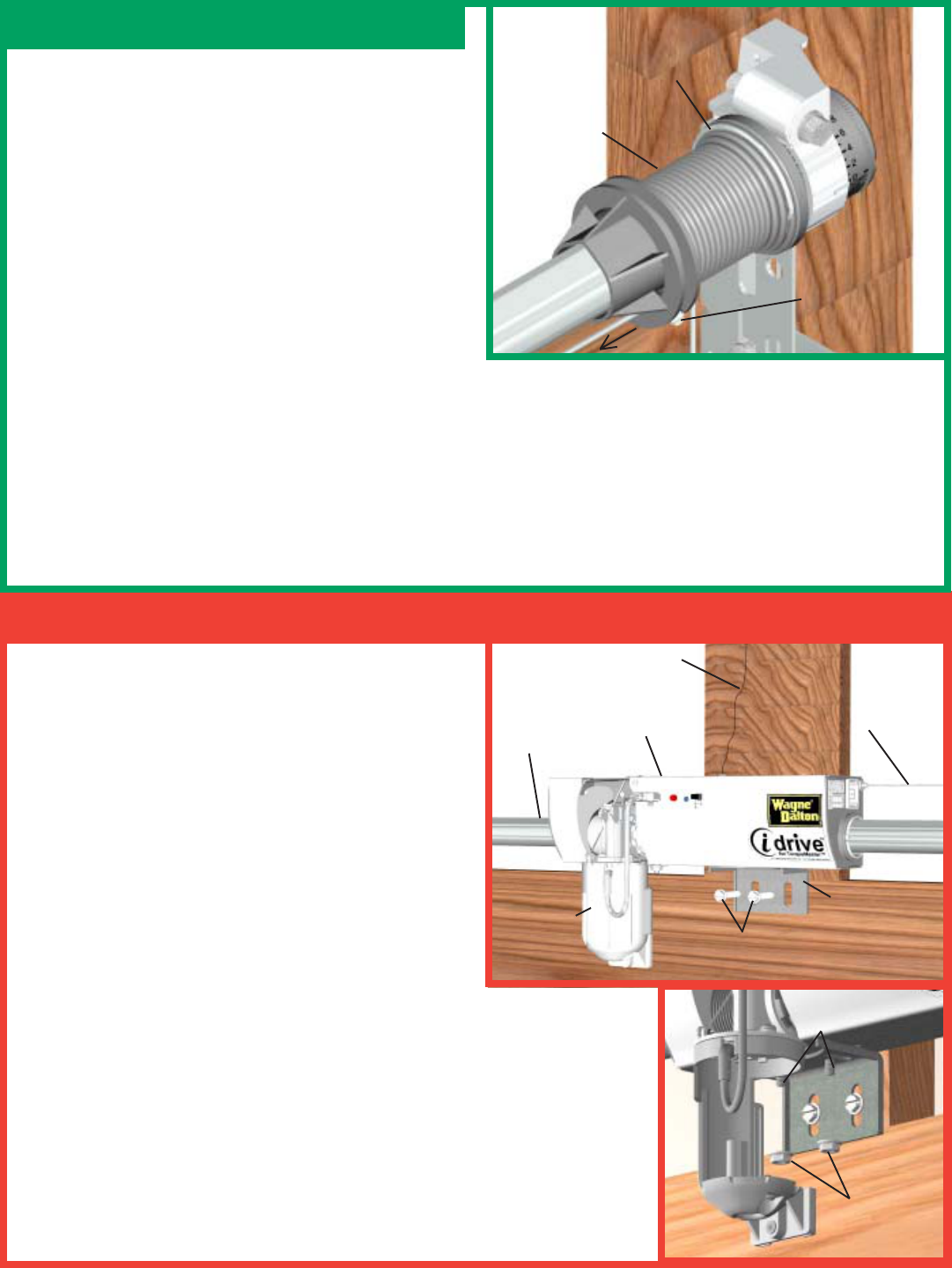
Install the right side counter gear, with the missing tooth toward the outside, away from the end bracket. Press
the counter gear onto the end bracket until snaps engage. Select the right hand counter cover and align the hex
of the counter cam with the end of the winding shaft. Also, align the “0” on the counter cover with the raised
rib on the end bracket. Press the counter cover against the counter gear until it locks into place. Repeat for left
hand side for double spring applications.
NOTE: No drive gear, counter gear or counter cover is required on left hand side for single spring applications.
Only an end bracket is needed.
IMPORTANT! At this time do not wind
counter balance springs!
(3mm)
(6mm)
3/32”(3mm)
HOLE
Slide the right hand end bracket over the drive gear.
Secure end bracket and the flagangle to the jamb using
(2)5/16 x 1-5/8” lag screws.
(2) 5/16 X 1-5/8
LAG SCREWS
END
BRACKET
END BRACKET
COUNTER
GEAR
MISSING
TOOTH
WINDING
SHAFT
RAISED RIB
“0”
COUNTER
COVER
HEX OF COUNTER
CAM
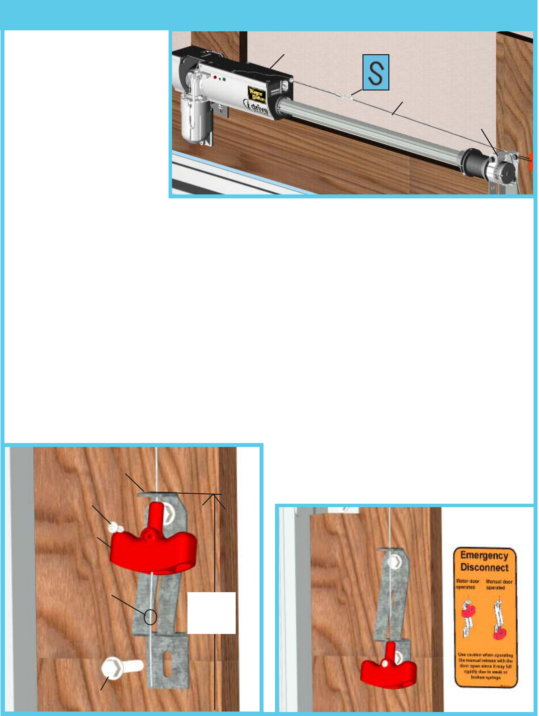
Locate the spring pad. The spring pad is a vertical
running board directly above the center of the door.
Remove (2) 1/4-20 flange nuts from bottom of opener.
NOTE: Do not discard flange nuts.
Place the support bracket underneath opener, to the right
side of motor, centered on spring pad. Level the torque
tube to the top of the door section with the idrive™
resting on the support bracket. Once torque tube is
level, secure support bracket to the spring pad with (2)
1/4 x 2" lag screws.
Lift and slide the opener over the support bracket,
aligning the mounting studs with the bracket slots.
Loosely fasten to mounting studs with the (2) 1/4-20
flange nuts.
Alternately, the disconnect cable can be pulled to allow motor to pivot up.
This will enable assembly of the support bracket to the opener first followed
by leveling of the torque tube and then attachment of support bracket to
spring pad. Remove the temporary orange label holding the antenna wire.
Straighten antenna and position up and slightly to the right as shown.
NOTE:
Do not tighten 1/4-20 flange nuts to opener studs at this time
.
NOTE:
idrive must be installed on a solid spring pad surface
.
13
ANTENNA
Step 11: Opener/Support Bracket Installation
OPENER
MOTOR SUPPORT
BRACKET
(2) 1/4 X 2”
LAG SCREWS
SPRING PAD
(2) 1/4-20
FLANGE
NUTS
MOUNTING
STUDS
Step 10: Cable Adjustments COUNTER
BALANCE
CABLE
DRUM
SET SCREW
Rotate the drum until the set screw faces directly away
from the header.
NOTE: Cable tension is set during the initial door
installation. If there is slack between the
counterbalance cable and the drum or unequal
tension between the right and left hand cables, the
cables will have to be readjusted. If there is no slack
and equal tension proceed to Step 11.
Beginning with the right side, Loosen the set screw
enough to adjust cable, approximately 2 turns. Pull on
the end of the cable to remove all cable slack. Check to
ensure the cable is aligned and seated in the first groove of the cable drum. Snug the set screw, then tighten an
additional 1-1/2 turns. Repeat for left side.
TORQUE
TUBE
DISCONNECT
CABLE
PULL
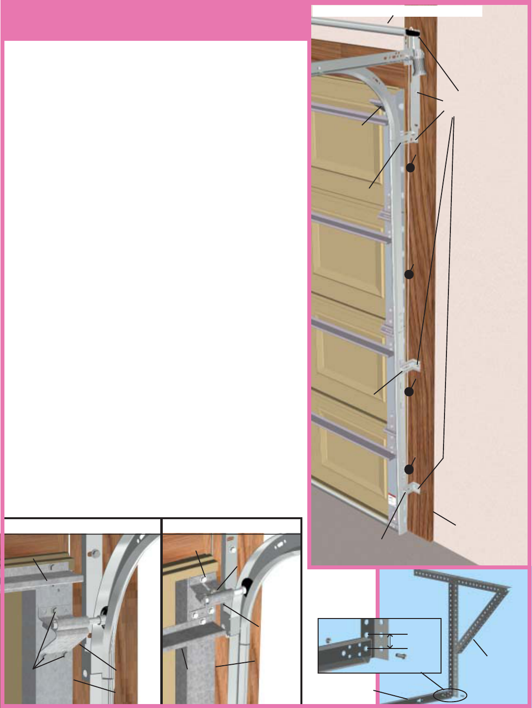
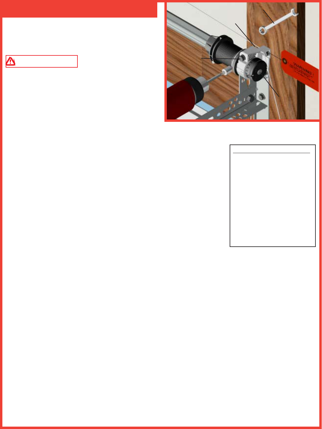
Attach the loose disconnect cable
(located in opener hardware bag)
to the opener with the “S” hook.
Close both ends of the “S” hook
to lock assembly together.
Thread the disconnect cable
through the hole in the right hand
end bracket, and remove all slack
between opener and bracket.
Mark a location on the right
jamb, 6 feet above the floor to
mount the handle bracket. Align top of the bracket with the mark. Fasten bracket to the jamb with (2) 1/4 x 1-
1/2" lag screws. Start the #6-20 x 1/2" screw into the handle. Thread the disconnect cable through the top of the
handle bracket and then the handle. Locate the handle in full upper position of handle bracket. Then remove all
cable slack between the opener and the top of the handle bracket. Tighten #6-20 x 1/2" screw into the handle
until snug, and then tighten screw an additional 1 to 1-1/2 turns to secure cable to handle. Trim off excess cable
from bottom of the handle.
NOTE: It is recommended that 1/4" lag screw location be pilot drilled using 1/8" drill bit.
CAUTION: Pull cable only enough to remove the cable slack. Pulling the cable more could cause opener to
disconnect from the torque tube.
Apply emergency disconnect label next to the mounted bracket. Use mechanical fasteners if adhesive will not
adhere.
Using the emergency disconnect, pull disconnect handle downwards and place it in the manual door operated
position. Use disconnect label for reference. Motor
will be rotated 90° from its packaged position.
NOTE: If motor does not pivot 90°, see
troubleshooting section in this manual.
Step 12: Disconnect Installation
RIGHT END
BRACKET
OPENER S-HOOK
14
DISCONNECT
CABLE
HANDLE
BRACKET
DISCONNECT
CABLE
#6-20 X 1/2”
SCREW
1/4” X 1-1/2” LAG SCREW
6’ to
floor
HANDLE
EMERGENCY
DISCONNECT LABEL
MOUNTED
BRACKET
Clamp locking pliers onto both vertical tracks just
above the third roller. This is to prevent the garage
door from rising while winding counterbalance springs.
WARNING FAILURE TO CLAMP
TRACK CAN ALLOW DOOR TO RAISE AND
CAUSE SEVERE INJURY OR DEATH.
IMPORTANT! DO NOT USE IMPACT GUN TO
WIND SPRING(S)
Beginning with the right hand side. Press and hold in
the canoe clip. Ensure the cable is in the first groove of the drum. Using an
electric drill (high torque gear reduced to 1300 RPM preferred) with a 7/16"
socket, carefully rotate right hand winding bolt clockwise, until counter shows
2-3 turns. This will keep the counterbalance cable taut while adjusting the left
hand side counterbalance cable. Repeat step for left side. NOTE: Single
spring applications require no spring winding on left hand side.
Ensure counterbalance cable tension is equal for both sides prior to fully winding
spring(s) to appropriate number of turns.
Carefully rotate the winding bolt head clockwise until the counter shows the
correct number of turns for your door. See the Spring Turn chart. Repeat for
the opposite side on double spring TorqueMaster™ systems. If door raises off
of floor remove 1/2 - 1 full turn from each spring before proceeding.
After spring is wound, hold the lock nut (in back of end bracket) stationary with a 7/16” wrench while rotating
the winding bolt clockwise until snug. Tightening of the lock nut prevents spring from unwinding. Repeat for
opposite side on double spring system.
IMPORTANT! Adjustments to the recommended number of turns may be required. AFTER REAR SUPPORT
ASSEMBLY IS COMPLETE, check door balance. If door raises off of floor under spring tension alone, then
reduce turns until door will rest on floor. A “hot” door such as this can cause idrive™ operation problems.
After checking/adjusting door balance, remove looking pliers from vertical track.
Door Height = Spring Turns
6’0” = 14 turns
6’-3” = 14-1/2 turns
6’-5” = 15 turns
6’-6” = 15 turns
6’-8” = 15-1/2 turns
6’-9” = 15-1/2 turns
7’-0” = 16 turns
7’-3” = 16-1/2 turns
7’-6” = 17 turns
7’-9” = 17-1/2 turns
8’-0” = 18 turns
Step 13-14: Wind Springs
15
Spring Turns
7/16” WRENCH
LOCK NUT
CANOE
CLIP
WINDING
BOLT
16
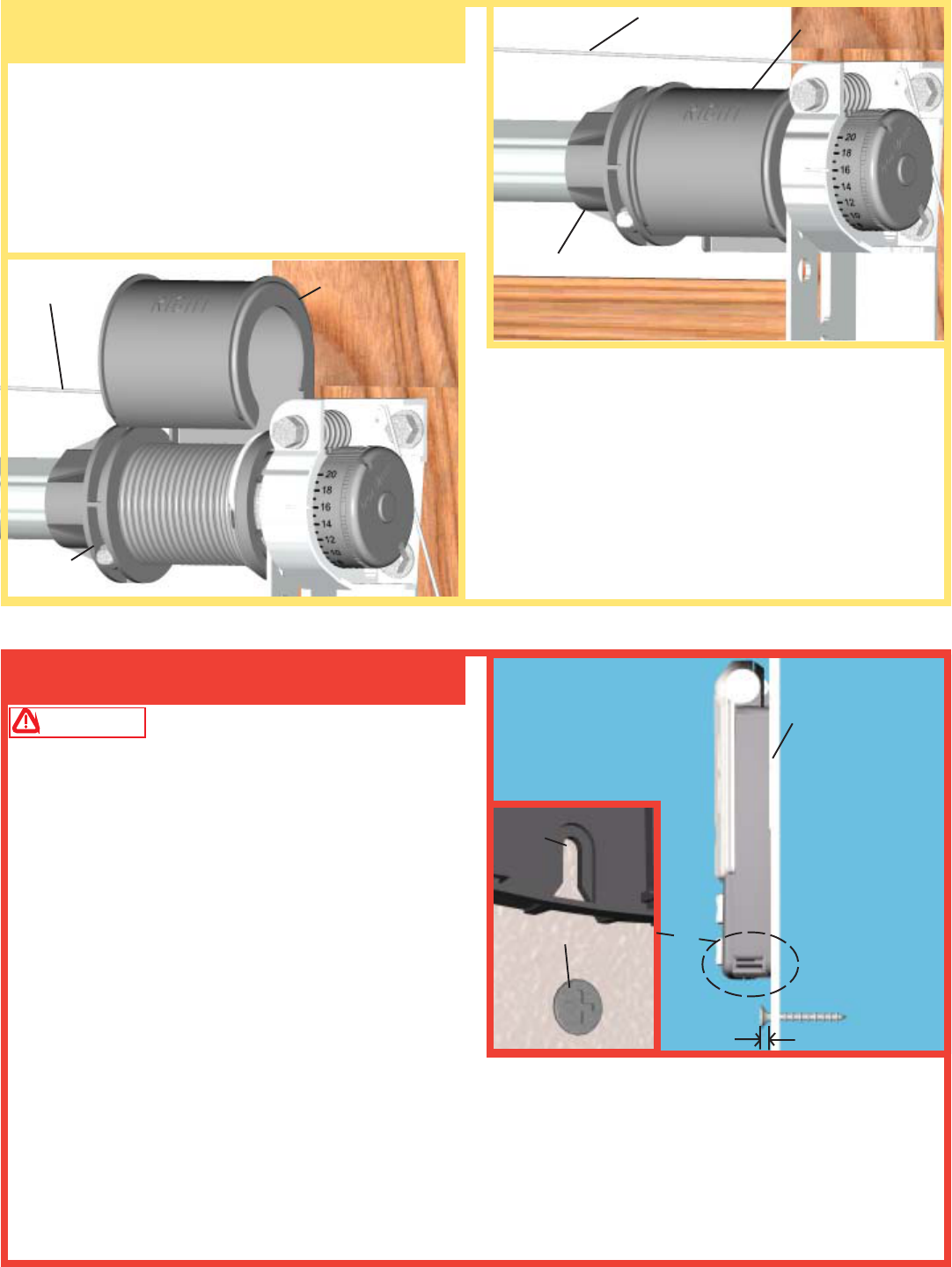
Drum wraps (supplied with TorqueMaster™
counterbalance systems) are identified as right and left.
To install, place the drum wrap over the cable drum
and under the idrive™ disconnect cable. Align the
outside flange over the outside edge of the cable drum
and push the drum wrap down onto the cable drum.
WARNING To prevent possible injury, install all
wall controls out of the reach of children and in a
location where the door can be seen before activating.
Do not mount push buttons near or next to garage door.
Select appropriate place to mount wall station. To keep
wall station out of the reach of children, locate it at
least five feet up from the floor. If possible, install on
wood framing. If fastening into drywall or concrete, use
anchors provided.
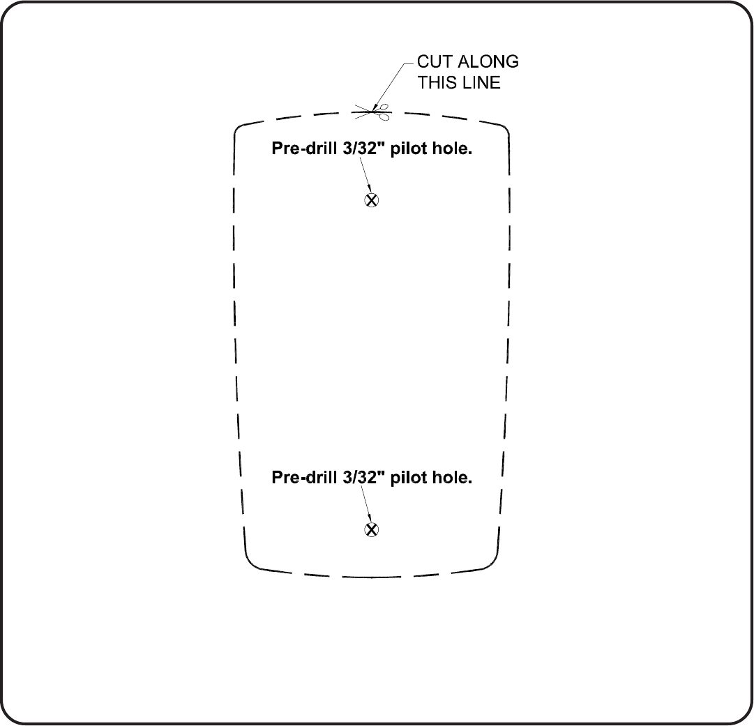
Using a 3/32" drill bit and the drilling template located
on page 36, drill the two mounting holes. Install lower
screw leaving 1/8" of the threads exposed. Slide wall
station keyhole slot onto the lower screw. Wall station
should slide onto screw, providing a snug fit. If necessary, remove wall station and loosen or tighten lower
screw. Once wall station is fitted snuggly on lower screw, install upper screw. Do not over tighten.
CAUTION: Over tightening the upper screw could deform plastic case.
Step 16: Wall Station Installation
Pre-Operation Installation
Step 15: Drum Wrap Installation DRUM WRAP
DRUM WRAP
CABLE
DRUM
CABLE DRUM
DISCONNECT
CABLE
DISCONNECT
CABLE
WALL
1/8”
SCREW
KEY
HOLE
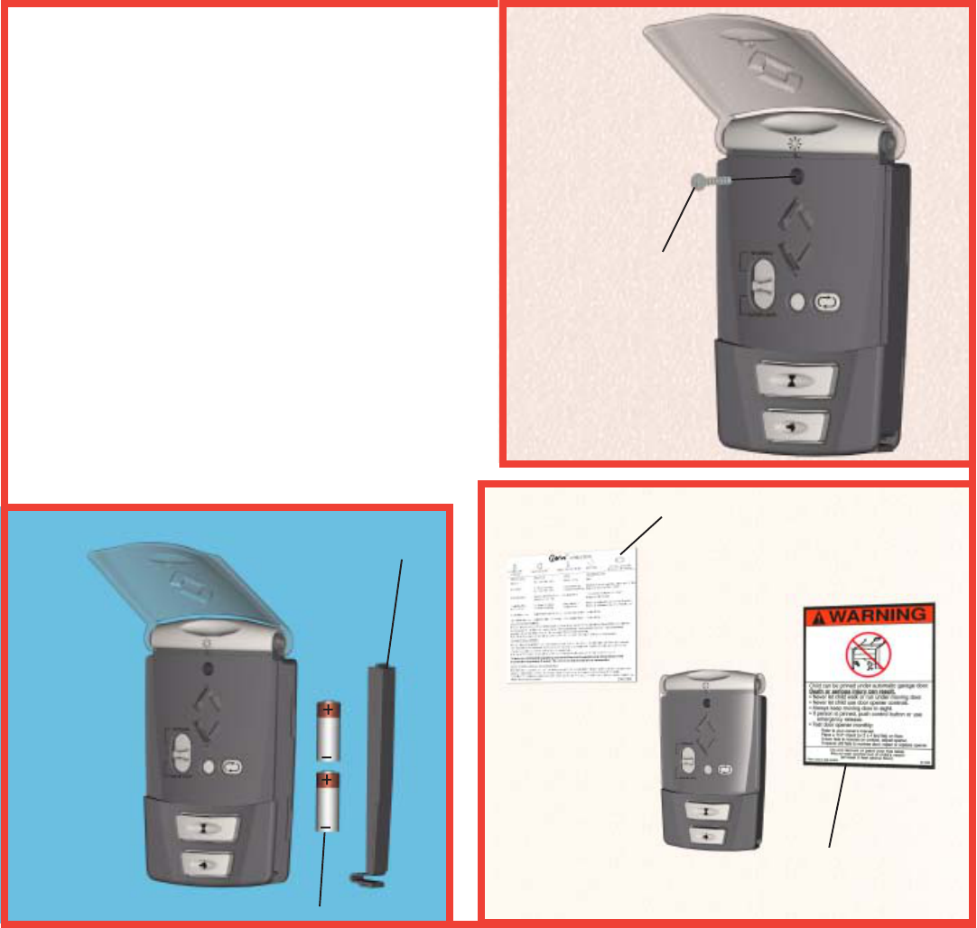
Battery Installation: Remove the battery cover
completely (right-hand side of wall station) by
disengaging the battery cover’s lower clip. Install two
AAA batteries into the wall station observing the
polarity, (+) and (-), of both batteries. After about five
seconds, the Up/Down red LEDs will begin to blink
momentarily every 1/2 second. Re-install the battery
cover by first inserting its top into the wall station then
inserting and securing its bottom. Apply wall station
reference label and entrapment label in convenient
location next to the wall station.
17
BATTERY POLARITY(+ AND -)
BATTERY
COVER
WALL
SCREW
WALL STATION
REFERENCE LABEL
ENTRAPMENT
LABEL
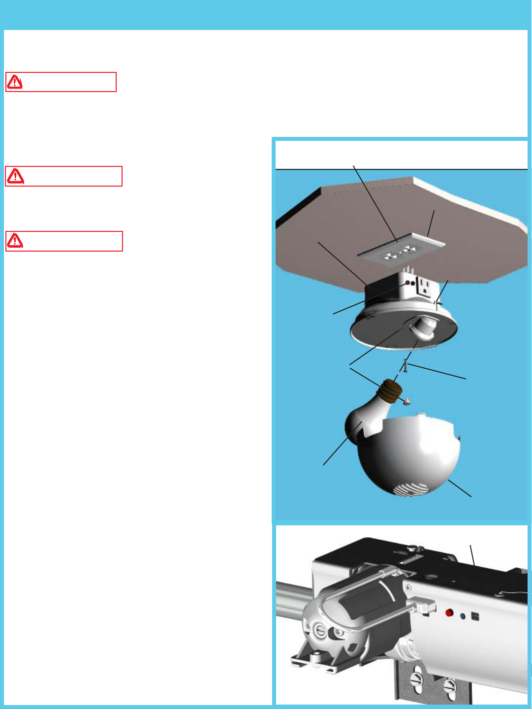
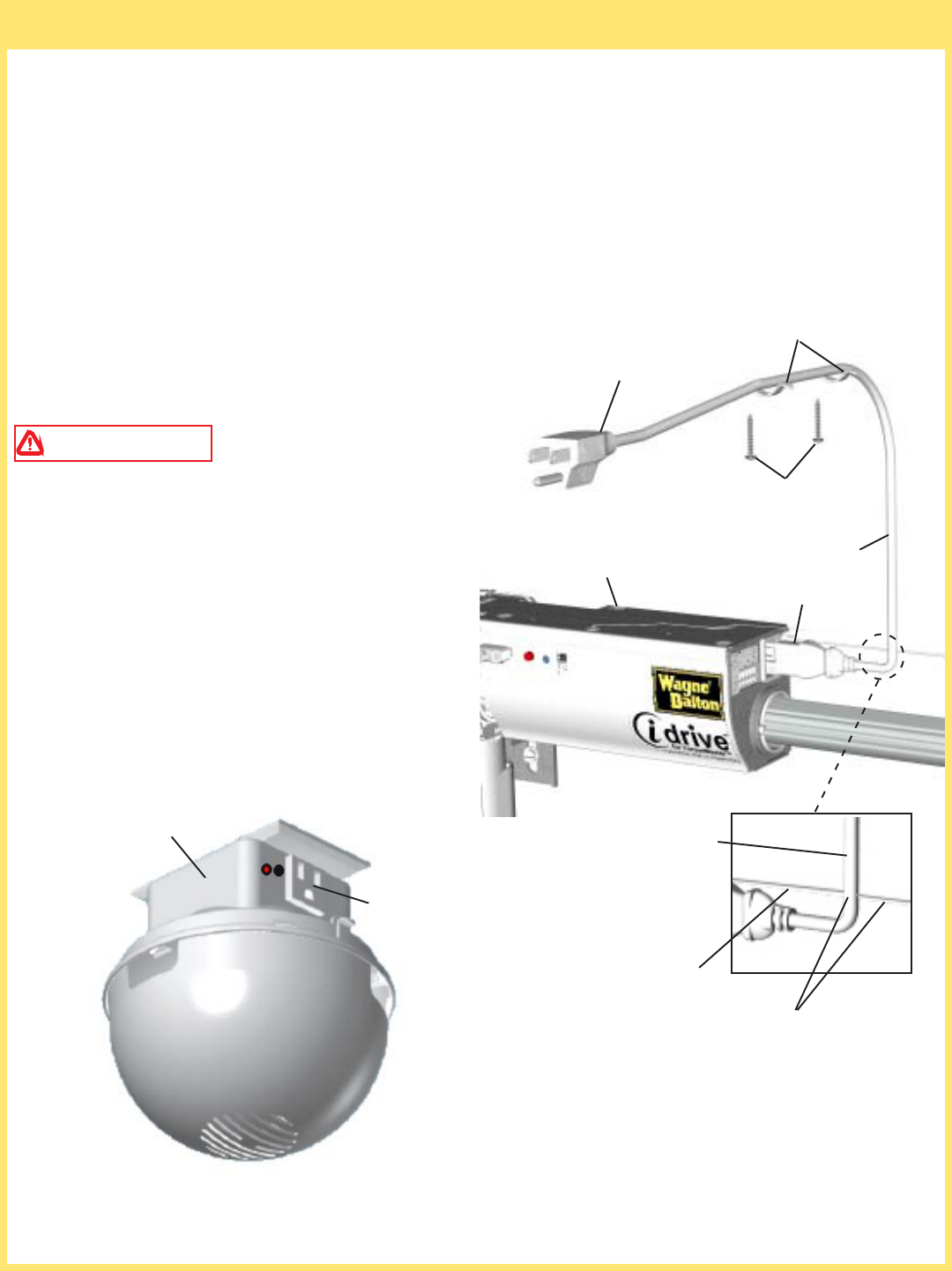
NOTE: RECEPTACLE COVER MUST BE INSTALLED
IN-BETWEEN THE LIGHT FIXTURE AND THE CEILING
Locate a duplex receptacle within line of sight of opener, when the door is in the open position.
Disconnect power to the receptacle at the fuse/breaker box before proceeding.
WARNING TO REDUCE THE RISK OF ELECTRICAL SHOCK, THIS EQUIPMENT HAS A
GROUNDING TYPE PLUG, THAT HAS A THIRD (GROUNDING) PIN. THIS PLUG WILL ONLY FIT
INTO A GROUNDING TYPE OUTLET. IF THE PLUG DOES NOT FIT INTO THE OUTLET, CONTACT
A QUALIFIED ELECTRICIAN TO INSTALL THE
PROPER OUTLET. DO NOT CHANGE THE PLUG
IN ANY WAY.
WARNING TO AVOID ELECTRICAL
SHOCK, DISCONNECT POWER TO THE
RECEPTACLE AT THE FUSE/BREAKER BOX
BEFORE PROCEEDING.
WARNING DO NOT INSTALL THE
LIGHT FIXTURE INTO A RECEPTACLE WITH A
METAL FACEPLATE.
NOTE: Door must clear light fixture when the door is
in the open position.
CEILING/WALL MOUNTING
Remove the center screw in the receptacle cover.
Holding receptacle cover in place, insert light fixture
into the receptacle that has the ground hole farthest from
center screw hole. Remove center hole plug from light
fixture to expose the screw hole. Secure light fixture
to receptacle with a #6-32 x 3/4” phillips pan head
screw. Replace hole plug into the screw hole in the
light fixture. NOTE: For temperature protection,
the hole plug must be in place prior to using the
light fixture.
PROGRAM LIGHT
Screw a maximum 75W light bulb into light socket
and snap diffuser into light fixture. Turn receptacle
power back on at fuse/breaker box. The light should
blink one time when the power is re-established.
NOTE: An accessory power outlet receptacle (600 Watt
Maximum) is provided on the light fixture.
Step 17: Light Fixture Installation
18
PROGRAM
LIGHT
DUPLEX
RECEPTACLE
LIGHT FIXTURE
DIFFUSER
HOLE PLUG #6-32 X 3/4”
PHILLIPS
PAN HEAD
SCREW
75W (MAX)
LIGHT BULB
(NOT IN-
CLUDED)
OPENER
THUMB
SCREW
19
NOTE: If safety sensors are included with this
opener proceed with this step. If they are not
included, skip this step and proceed with step 20.
Safety sensors are required if opener is installed
on a non-pinch resistant door.
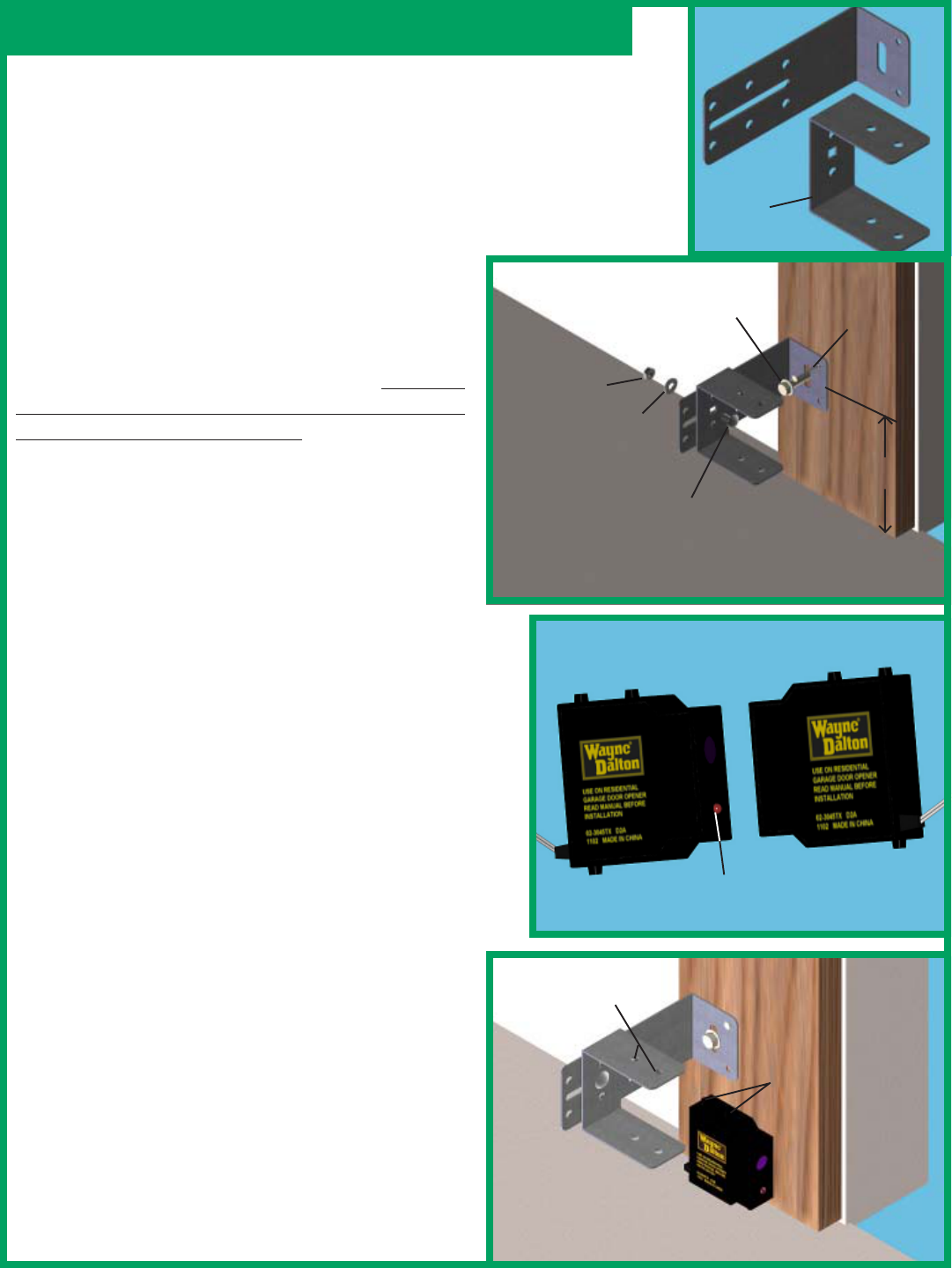
Select a mounting position 5 inches above the floor to
center line of wall mounting bracket. The sending and
receiving units should be mounted inside the door
opening to minimize any interference by the sun.
However, the sensors should be mounted as close to
the door track or inside edge of the door as possible to
offer maximum entrapment protection. It is very
important that both wall brackets be mounted at the
same height for proper alignment.
The brackets may be temporarily mounted to the jamb
with a 1” flat head nail (provided) using the small hole
above the slot. Using two 5/16 x 1-1/2” lag screw
(provided), permanently mount the wall mounting
brackets to both door jambs. In some installations it
may be necessary to attach a wooden spacer to the wall
to achieve the required clearance.
Attach the “U” brackets to the wall brackets with a
1/4-20 carriage bolt, washer and nut (provided). Insert
the bolt from the inside of the “U” bracket and hand
tighten only at this time.
Identify which side of the garage door opening (if any)
is “likely” to be exposed to sunlight. Since sunlight
may affect photoelectric sensors, you should mount
the sending unit (not the receiving unit) on the side of
the door opening most exposed to the sun.
NOTE: If wires must be lengthened or spliced into
prewired installation, use wire nuts or suitable
connectors.
Attach the sending and receiving units to the “U”
brackets by inserting their tabs into the respective holes.
Step 18: Photoelectric Safety Sensor Installation
NAIL
WALL
MOUNTING
BRACKET
NUT
WASHER
1/4-20 X 1/2”
CARRIAGE BOLT
(1) 5/16 X 1-1/2”
LAG SCREWS
5”
“U”
BRACKET
RECEIVING UNIT
SENDING UNIT
HAS NO LED
LIGHT
LED ALIGNMENT
LIGHT
TABS
TOP & BOTTOM
TAB HOLES
TOP & BOTTOM
20
VIEW OF THE OPENER
FROM THE FRONT
JUMPER INSTALLED
ON PINS “PE”
OPENER
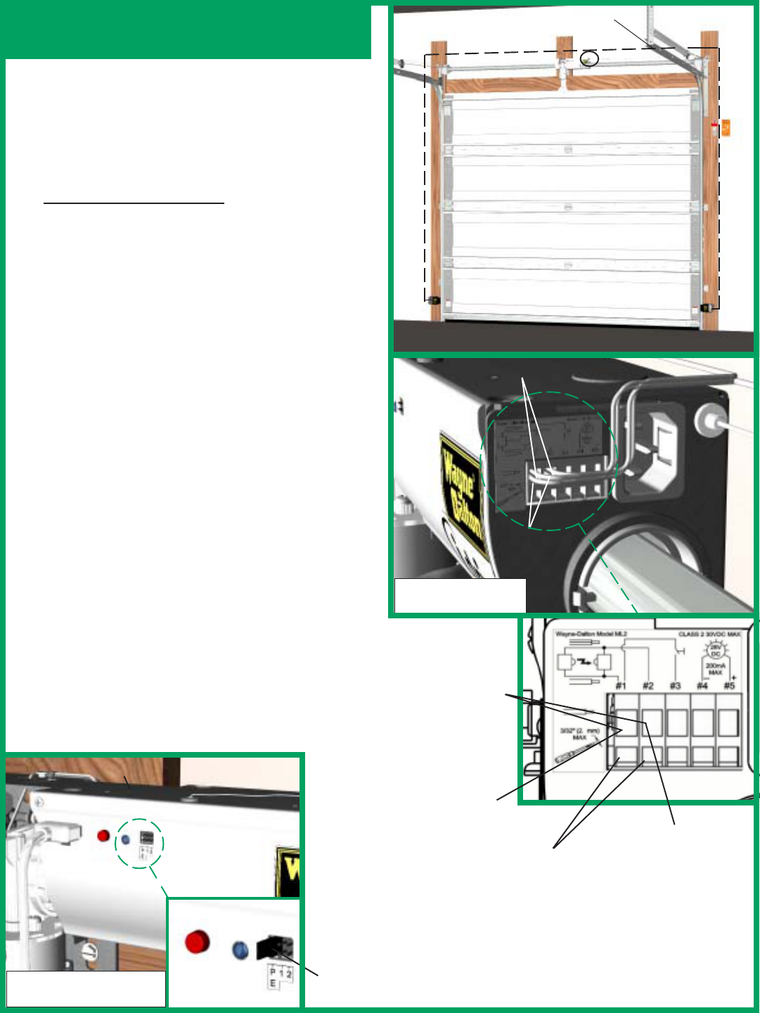
Uncoil wires from photoelectric sensors and route
wires up garage wall and along door header towards
the right side of the opener
.
Route wires above torque
tube and tack wires in place with insulated staples (not
supplied). Take care to run wires in a location where
they will not interfere with the operation of the door
and do not staple through wire.
Connect photoelectric sensors to the opener terminal
block in right side of the opener. Separate wire ends
and strip about 1/2” of insulation off each of the wire
ends. Insert a 3/32” (2.5mm) max. width flathead
screwdriver into the lower hole #1 of the terminal
block. Twist screwdriver to open wire clamp in upper
hole #1 of terminal block. Insert both sender and
receiver solid white wires into upper hole #1 until the
wires bottom out and release screwdriver tension.
Insert both sender and receiver wires (white with black
stripe) into upper hole #2 by the same process on lower
hole #2 of terminal block. Once wires are connected
install jumper on to the left most set of pins labeled
“PE”, located on the front of the opener.
IMPORTANT! Keep sender/receiver wires away
from moving members.
One wire has a black stripe. Be sure to observe polarity.
Apply tension to external wires to test for secure
connection. Check that the wires are stapled in place
and staples have not cut wire insulation.
INSERT SENDER
WIRES
INSERT
RECEIVER
WIRES
WIRE ROUTING
Photoelectric Safety Sensor
Installation Continued
INSERT WIRES INTO
UPPER HOLES
RIGHT HAND SIDE
VIEW OF OPENER
INSERT SCREW-
DRIVER INTO
LOWER HOLES
SOLID WHITE
WIRES WHITE WIRES WITH
BLACK STRIPE
21
Step 19: Power Connection (Standard Wiring)
WARNING TO REDUCE THE RISK OF
ELECTRICAL SHOCK, THIS EQUIPMENT HAS
A GROUNDING TYPE PLUG, THAT HAS A THIRD
(GROUNDING) PIN. THIS PLUG WILL ONLY FIT
INTO A GROUNDING TYPE OUTLET. IF THE
PLUG DOES NOT FIT INTO THE OUTLET,
CONTACT A QUALIFIED ELECTRICIAN TO
INSTALL THE PROPER OUTLET. DO NOT
CHANGE THE PLUG IN ANY WAY.
Plug the female end of power cord into the inlet connector on the right side of opener. Plug the other end of
the opener power cord into the nearest convenient power receptacle. (If the power cord is not long enough to
reach the closest receptacle, the idrive™ Powercord Extender kit is available, otherwise contact a service
person for further options.) As soon as power is applied to the opener, the light fixture will light up. If the
light fixture does not light, adjust the receiver module alignment. Unplug, then plug back in the power cord.
Repeat this process until the light comes on. Ensure there is no obstruction between the opener and the light
fixture. Refer to Step 17: Light Fixture Installation for the alignment procedure.
Excess power cord length must be routed and contained safely away from any moving members.
NOTE: Do not permanently attach power cord to building!
Use only the flexible plastic clips supplied with the opener
#6 X 7/8 WOOD
SCREWS
POWER CORD
FEMALE END
POWER CORD
DISCONNECT
CABLE
NO INTERFERENCE BETWEEN
POWER CORD AND DISCONNECT
CABLE
OPENER
POWER OUTLET
RECEPTACLE
LIGHT FIXTURE
PLUG INTO NEAREST
CONVENIENT POWER
OUTLET
PLASTIC CLIPS
22
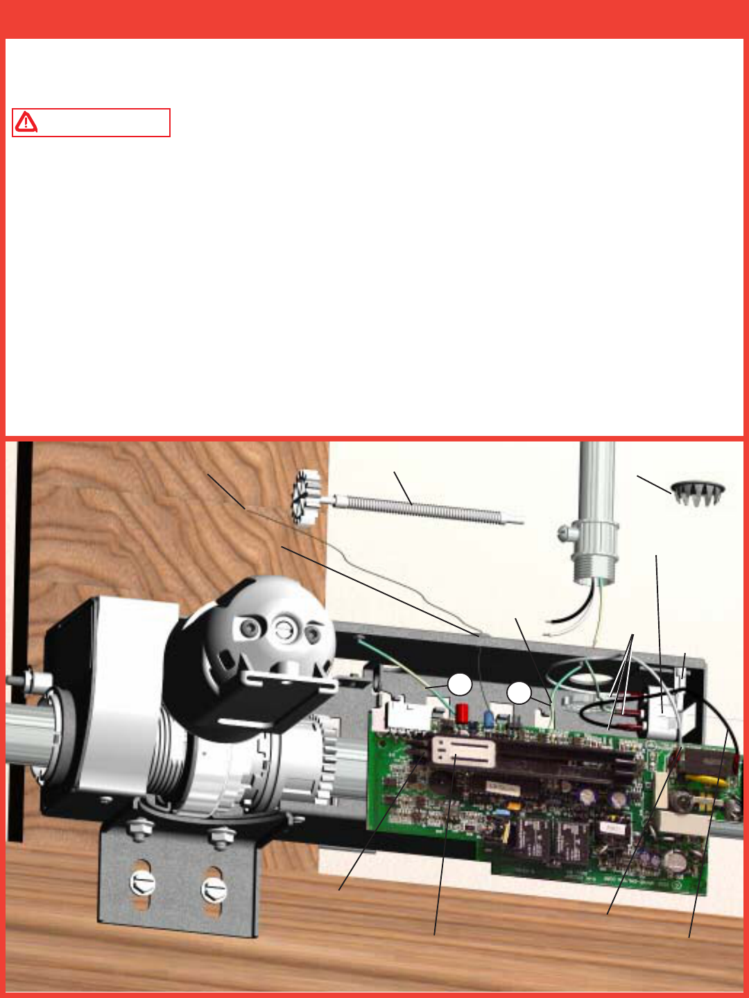
Where required by local codes, the opener can be permanently wired. Services of a licensed electrician can be
obtained to perform the following permanent wiring procedure.
WARNING DISCONNECT POWER AT FUSE/BREAKER BOX BEFORE PROCEEDING.
Using a phillips head screwdriver, remove the two screws from the right hand cover and unplug motor power
cable. Remove right hand cover from the opener to expose electronics and wiring.
Remove potentiometer gear and finishing plug. Unsnap the circuit board from the chassis stand-offs and
remove the circuit board as shown. NOTE: Do not disconnect the two ground wires (A & B) from the circuit
board or the chassis. Cut three wires, leading to the inlet connector, at the base of the connector. Route wires
inside of the conduit through the top hole in the opener Using wire nuts, splice each conduit wire with the
corresponding wire inside the opener as follows: opener black (line), opener white (neutral), and opener
yellow and green (ground). Reinstall the circuit board back into the opener chassis and snap the board back
into the chassis stand-offs. NOTE: Make sure antenna wire is routed through the chassis grommet when
board is installed. Confirm pot position* shown below. Reinstall the potentiometer gear, right hand cover,
and screws. Plug in the motor power cable.
Step 20: Power Connection (Permanent Wiring Option)
*POSITION POT NUT 1/16” - 1/8”
AWAY FROM LEFT STOP
ANTENNA POTENTIOMETER GEAR REMOVE AND DIS-
CARD FINISHING
PLUG
CHASSIS
STAND-
OFF
CUT
WIRES
HERE
GREEN &
YELLOW
(GROUND)
“A” “B”
GROMMET
WHITE
(NEUTRAL) BLACK
(LIVE)
INLET
CONNECTOR
*POTENTIOMETER
GEAR CLIP
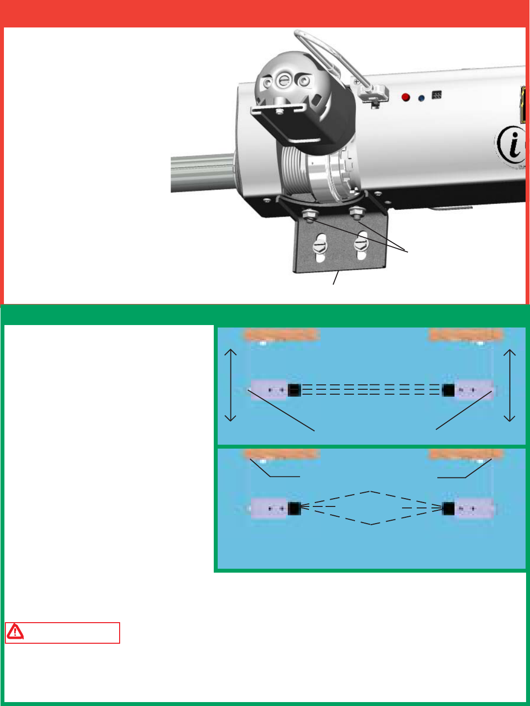
Tighten both 1/4-20 flange nuts,
securing the opener to the
support bracket.
With the emergency disconnect still in the
manual door operated position: Manually
raise the door to the full upward position.
Then, manually lower the door to the full
closed position verifying freedom of
movement and good door balance.
SUPPORT BRACKET
1/4-20 FLANGE NUTS
23
Step 21: Securing the Opener
IMPORTANT! - This infrared safety
sensor sends an invisible beam of light from
the sending unit to the receiving unit across
the pathway of the door. The door opener
will not operate until the safety sensor is
connected to the power unit and properly
aligned. If the invisible beam of light is
obstructed, an open door cannot be closed
by the transmitter or a momentary activation
of the wall mounted push button. However,
the door may be closed by holding your
finger on the wall push button (constant
pressure) until the door travels to a fully
closed position. The safety sensors must be
aligned by moving the sending and receiving
units in or out (see Fig. 1) until the alignment
light on the receiving unit comes on. The 1/
4-20” carriage bolt can be loosened to move
the unit in or out, as required. If you have difficulty aligning beams, check that both brackets are mounted at the
same height and remount if necessary. Additional minor adjustments can be made by lightly bending the
mounting brackets (see Fig. 2).
WARNING FAILURE TO MAKE ADJUSTMENTS COULD RESULT IN SEVERE OR FATAL
INJURY.
Once the alignment light comes on, tighten all bolts and mounting screws. Finish securing all wire making sure
not to break or open any of the conductors. Loop and secure any extra wire.
Step 22: Photoelectric Safety Sensor Alignment
IN
OUT
IN
OUT
1/4-20 CARRIAGE BOLTS
Top View
Align in Center
For this adjustment bend bracket at
wall mount
FIG. 1
FIG. 2
Top View
Align in Center
(In/Out)
NOTE: Good door balance and freedom of
movement are critical to the safety and
performance of the door opener. If door is very
heavy to lift or if springs are too tight making
door hard to close or if door sticks or binds in
the track, now is the time to correct it.
24
NOTE: The following steps describe the process to activate the Wireless Wall Station security code, changing
security code and programming Wireless Wall Station to the opener.
NOTE: The user must change the wall station’s security code before using the wall station.
Activating the Wall Station:
NOTE: Activation of the wall station is only required at installation
and before first use of the wall station. Afterwards, the security code
can be changed.
1. Press and hold the wall station’s Light button. The Up/Down button
red LEDs will blink rapidly.
2. After 2 seconds, the LEDs will turn on continuously indicating a
successful activation. Release Light button. The wall station is now
ready to be programmed to the opener.
Changing the Wall Station’s Security Code:
If desired, the wall station’s security code can be changed to a new,
randomly selected security code.
1. Press and hold the wall station’s Light button for approximately 10
seconds until the wall station’s Up/Down red LEDs begin to blink
rapidly.
2. Once the LEDs start blinking, release the wall station’s Light
button; the LEDs will turn off.
3. Press and hold the wall station’s Light button again. The LEDs
will light for approximately 5 seconds.
4. After approximately 5 seconds the LEDs will begin to blink on
and off. Release the Light button.
5. The wall station’s LEDs will blink on and off three times
indicating a successful security code change. The wall station must
now be reprogrammed to the opener.
Wall Station Programming
To program wall station:
1. Verify the emergency disconnect handle is in the manual door operated position
(lower position). This is for safety reasons.
2. On the front cover of the opener, press and release the red program button; the
opener will beep once, indicating activation of the program mode. The opener will
remain in program mode for 30 seconds.
3. Press and hold the wall station light button until the opener beeps one time. The
wall station is now programmed.
4. Return the emergency disconnect handle to the motor operated position (upper
position).
No beeping response of the opener during the wall station programming indicates a
programming failure. Repeat programming Steps 1-4.
NOTE: Programming failure can occur during the wall station programming if the
remote control is too close to the opener during the programming sequence. Perform
the programming with a minimum of six feet between the remote control and the
opener.
Step 23: Wireless Wall Station Security Code Activation, Changing Security
Code and Programming
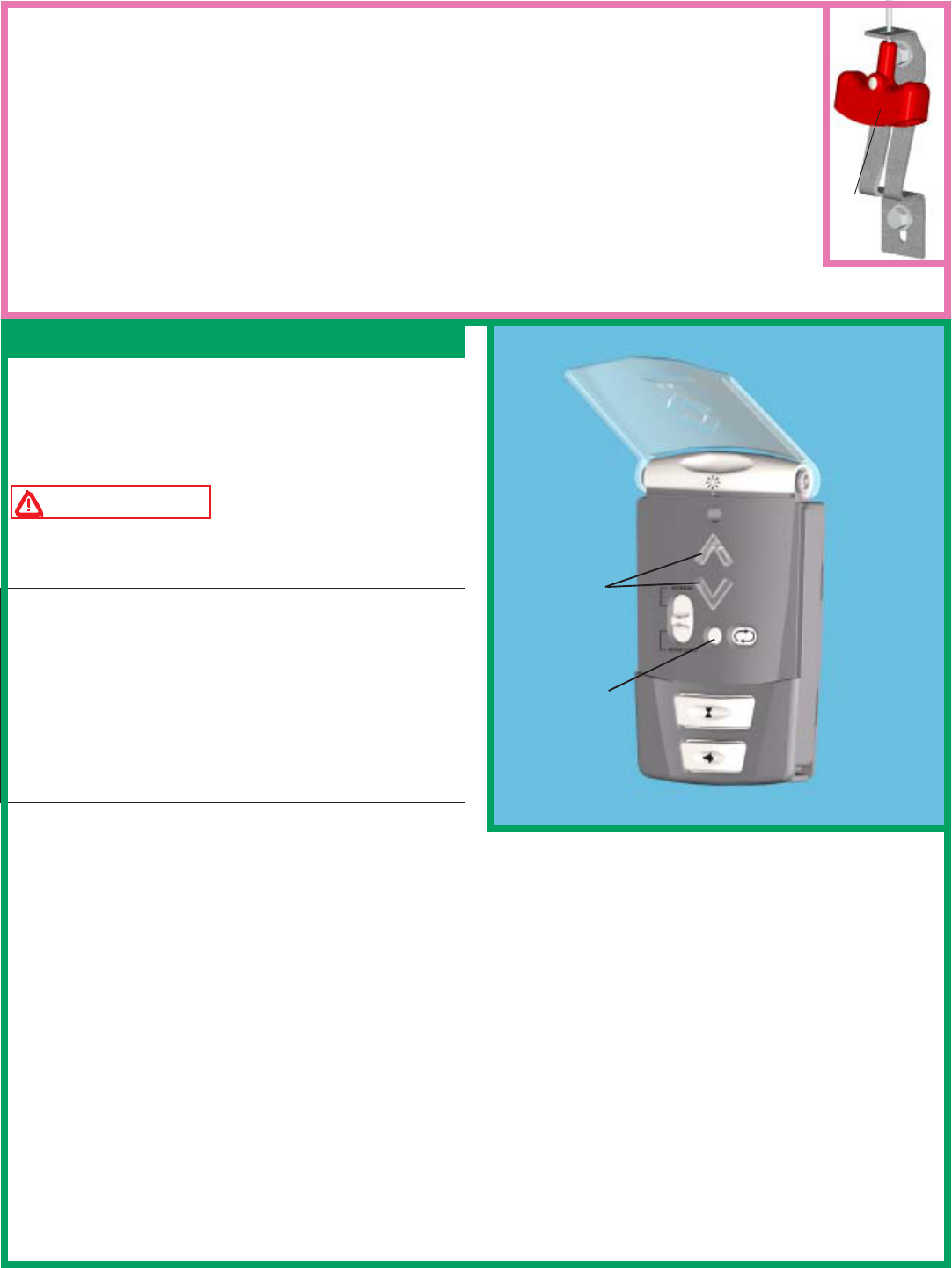
LIGHT
BUTTON
UP/DOWN
BUTTON
OPENER
MOTOR IN UP
POSITION
RED PROGRAM
BUTTON
HANDLE IN
MANUAL
OPERATED
POSITION
The install routine automatically sets the door open
and close limits and calibrates obstruction sensing.
During install routine, the door will move up and down
twice. Always keep a moving door in sight and away
from people and objects until it is completely closed.
WARNING TO AVOID INJURY, NO ONE
SHOULD CROSS THE PATH OF A MOVING
DOOR!
NOTE: If no obstructions interfere with the door when
manually opened and closed, proceed to Step 24 a.
However, if an object such as a ceiling beam obstructed
the door from opening completely, set a custom upper
limit during the install routine, Step 24 b.
NOTE: The door must be in its fully closed position
and the disconnect handle must be in the motor operated
position (upper position) to initiate the install routine.
Step 24 a: Install routine with standard upper limit
Press and hold the profile button for five (5) seconds,
or insert programming tool into the center hole as shown, push and release internal button. The opener will
beep twice, indicating the activation of the install routine (release profile button or remove programming tool
from wall station). The door will now move to the full open position and stop. Then, the door will close
completely. Next, the door will go through one more up/down cycle. Once this is complete, the door limits are
set and the installation is complete.
Step 24 b: Install routine with custom upper limit
Press and hold the profile button for five (5) seconds or push and release internal button. The opener will beep
twice, indicating the activation of the install routine. When the door moves to the desired height, at least four
feet off the ground, press the up/down button on the wall station. The door will stop and then close completely.
Next, the door will go through one more up/down cycle. Once this is complete, the door limits are set and the
installation is complete. Alternately: After an install routine has been completed, the door can be disconnected
and manually moved to the desired upper limit. Reconnect door and initiate a new install routine from the new
upper position.
25
Step 24: Install Routine
NOTE: The first wall station command, after programming, will only move the door through a
six-inch up/down cycle. Normal door operation will occur on the second usage of the wall
station. The six inch door move cycle will not happen if the install routine has not been run.
NOTE: The opener can be activated by up to six remote control devices (including wall station,
transmitter, and keyless entry devices.) If a seventh control is programmed, the first of the
programmed controls will be overridden and will no longer activate the opener.
CAUTION: For safety reasons, manually disconnect the opener from the door using the
emergency disconnect handle prior to erasing remote controls. To clear programming of all
remote control devices, press and hold the opener’s program button for approximately ten seconds.
When the opener beeps three times, all remote controls are erased. and the opener.
MOTOR
OPERATED
POSITION
UP/DOWN
BUTTON
PROFILE
BUTTON
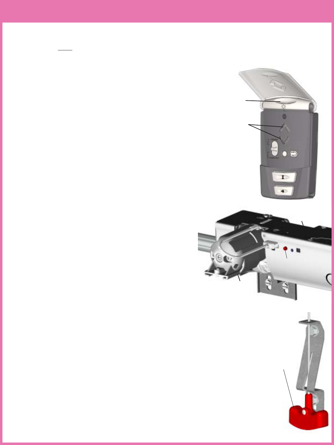
Step 26: Lock Arm Installation
(537mm) (502mm)
WD 15” RADIUS WD 12” RADIUS
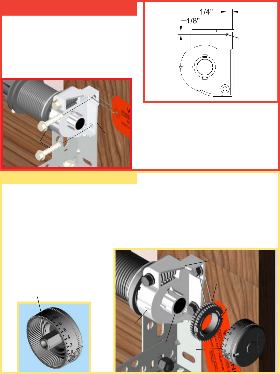
Place the emergency disconnect in
the manual operated position, motor
will pivot to the up position. Insert
the lock arm into the motor groove
and align the proper hole depending
on your track radius. To recognized
the Wayne-Dalton track radius
being used, measure the length of
the flagangle and TorqueMaster™
end bracket and compare to the diagram. Some tracks are stamped with radius on the side of the track. Once
track radius has been identified, secure the lock arm to the motor with (1)
M5 x 0.8 phillips pan head screw. After assembly of the lock arm, manually
raise and lower the door and verify that the lock arm does not interfere with
the door. If there is interference between the door and the lock arm, proceed
to Page 40 for lock arm troubleshooting. NOTE: Do not operate the door
if there is interference between the lock arm and the door. Reconnect
the door to the motor operated position. Activate a motor operated up/down
cycle to confirm
clearance. Refer to
Step 27 for final
adjustments.
detent pin CLOCKWISE in 1/4 turn increments. Operate the door to confirm each adjustment. If the motor
pivots to soon, adjust detent pin again. Repeat procedure until motor pivots to full down position when the door
is completely closed.
26
Step 25: Detent Adjustment (if required)
IMPORTANT! - FOR SYSTEM SECURITY: The motor is
designed to pivot down after the door closes completely. If the
motor does not pivot or pivots too soon, the detent may need to be
adjusted in order for the door lock feature to work properly.
IMPORTANT! Before making any detent pin adjustments, check
and adjust door balance. Door should not raise off of floor with
spring tension alone, nor should it free fall from any open position.
The normal amount of pressure the opener uses to pivot the motor
downward is preset at the factory via the detent pin adjustment screw. Due to variations in door installations, a
detent pin adjustment may be needed in order to properly pivot the motor.
A.) If the motor does not pivot down, or pivots down only partially, the detent pin is set too hard. Using a flat
head screwdriver, turn the detent pin COUNTER CLOCKWISE in 1/4 turn increments. Operate the door to
confirm each adjustment. If the motor does not pivot on door closing adjust detent pin again. Repeat procedure
until motor pivots to full down position when the door is completely closed.
B.) If the motor pivots down prematurely (before the door is completely closed) or if the motor is “slapping”too
aggressively against the top of the door, the detent pin is set too soft. Using a flat head screwdriver, turn the
DETENT PIN
mrAkcoL noitisoP
NOTLADENYAW-DW DNALTROPNOTLADENYAW-OP *EPYTKCART
kcarT suidaR ledoMrooD
1DW
OPOP
)mm503("21 "21 "01
0009,0008 seireS0009 0009,0008
2OP"21seireS0008
3DW
OP )mm803("51 "41 0009,0008 seireS0009
4OP"41seireS0008
13
2
4
LOCK
ARM
MOTOR
GROOVE
MOTOR
M5 X 0.8 PHILLIPS
PAN HEAD SCREW
REFER TO TABLE BELOW
27
Custom pet position: Normal install routine sets the pet position to
approximately eight inches above the ground. The pet opening height
may be changed to open anywhere between 8” and 30” above the ground.
To change the automatic pet opening height refer to the following
procedure:
1. After completion of the normal install routine, with the door in the
closed position, place the disconnect handle in the manual operated
position.
Manually position the door to the desired pet opening height (between 8”
and 30” above ground) and return disconnect handle to the motor operated
position.
2. Simultaneously depress the pet and up/down buttons on the wall station. The opener will beep once. The pet
button is now programmed to automatically open the door to this custom height.
NOTE: The opener will NOT accept programmed pet lock position if door is below 8” or higher than 30”.
NOTE: Activation of the normal install routine will reset the pet position to the default eight inch target height.
For use of the pet button see Operation section.
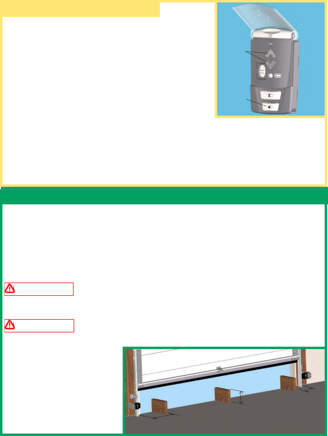
Step 28: Photoelectric Obstruction Sensor Test
12”
6” 12”
NOTE: Perform this step only if photoelectric safety sensors were installed during step 18. Otherwise proceed
to step 30.
Starting with the door in the fully open position, place a 6” high object on the floor progressively one foot from
the left side of the door, center of door and one foot from the right side of the door. In each position, activation
of the opener with the wallstation up/down button should cause the door to move no more than one foot, stop
and then reverse to fully open position. The same 6” high object when placed on the floor, while door is
closing, should also cause the door to reverse.
WARNING WHEN PERFORMING THIS PART OF THE TEST, DO NOT PLACE YOURSELF
UNDER DESCENDING DOOR, OR SEVERE OR FATAL INJURY MAY RESULT.
WARNING IF THE OPENER DOES NOT RESPOND PROPERLY, OR FAILS THESE TEST,
HAVE A QUALIFIED SERVICE PERSON MAKE NECESSARY ADJUSTMENTS/REPAIRS. FAILURE
TO MAKE ADJUSTMENTS COULD
RESULT IN SEVERE OR FATAL
INJURY.
Step 27: Custom Settings
UP/DOWN
BUTTON
PET
BUTTON
28
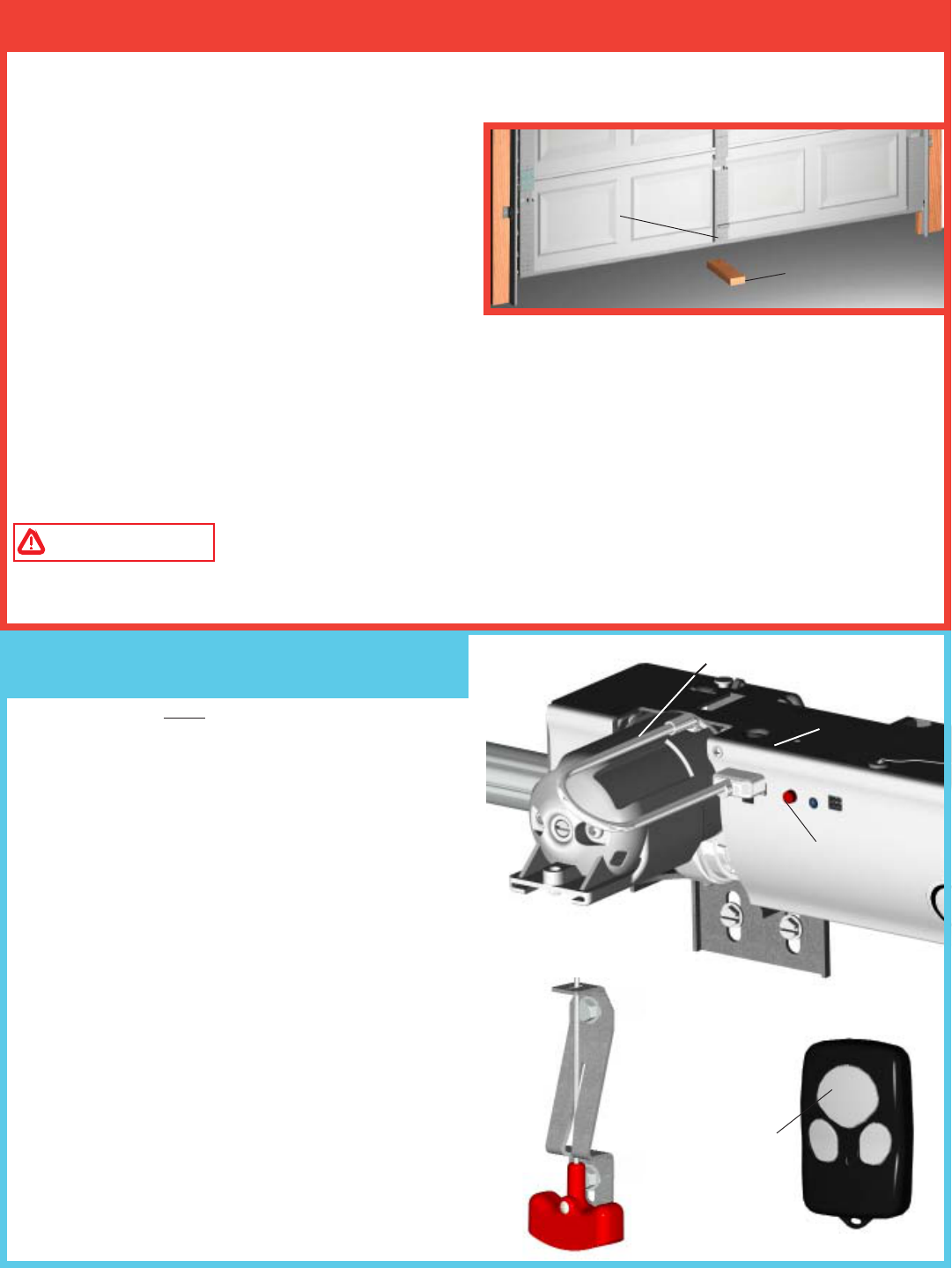
After installing the opener, the door must reverse when it: contacts a 1-1/2" (38mm) high object (or a 2 x 4
board laid flat) on the floor. To verify proper operation:
1. Using the wall station, activate the door to the fully
open position .
2. Place a 2 x 4 board laid flat on the garage floor
under the door path.
3. Activate the door to the closed position with the
wallstation; upon contacting a solid object, the door
will stop, then reverse direction within two seconds and travel to the full open position.
If the door does not respond to the required tests, remove 2 x 4 and repeat install routine making sure the door
is in the fully closed position prior to activation.
If problem persists contact Wayne Dalton Customer Service (888) 827-3667
WARNING IF OPENER DOES NOT RESPOND PROPERLY AND FAILS EITHER OF THE
TWO TESTS (28 AND 29), DOOR MAY CAUSE A SEVERE OR FATAL INJURY. HAVE A QUALIFIED
SERVICE PERSON MAKE NECESSARY REPAIRS.
Step 29: Contact Obstruction Test
NOTE: The user must change the transmitter’s security
code before using the transmitter.
This code sequence is only necessary the first time
the transmitter is used.
Overview: When changing the transmitter’s security
code, the user will have to hold the large button down for
approximately 10 seconds, then release the button
momentarily, and finally hold the button down again for
approximately 5 seconds.
CHANGING THE TRANSMITTER’S SECURITY
CODE:
1. Press and hold the large transmitter button for
approximately 10 seconds until the transmitter’s LED
begins to blink rapidly. Once the LED starts blinking,
release the large transmitter button; the LED will turn
off.
2. Press and hold the large transmitter button again (LED
will light) for approximately 5 seconds. After
approximately 5 seconds the LED will begin to blink on
and off. Release the large button. The transmitter’s LED
will blink on and off three times indicating a successful
security code change. The transmitter is now ready to be
programmed to the opener.
CENTER OF
DOOR
2 X 4 LAID FLAT
ON FLOOR
HANDLE IN MANUAL
OPERATED POSITION
OPENER
LARGE
BUTTON
MOTOR IN UP POSITION
RED PROGRAM
BUTTON
Step 30: Transmitter Security Code
Change and Programming

TRANSMITTER PROGRAMMING:
To program transmitter:
1. Place the emergency disconnect handle in the manual door operated position. This is for safety reasons.
2. On the front cover of the opener, press and release the red program button; the opener will beep once,
indicating activation of the program mode. The opener will remain in program mode for 30 seconds.
3. Press and hold the desired transmitter button until; the opener beeps once. The transmitter is now programmed.
4. Return the emergency disconnect handle to motor operated position.
NOTE: No beeping response of the opener during the transmitter programming indicates a programming failure.
Repeat programming 1-4.
NOTE: Programming failure can occur during the transmitter programming if the remote control is too close to
the opener during the programming sequence. Perform the programming with a minimum distance of six feet
between the remote control and the opener.
NOTE: The first transmitter command, after programming, will only move the door through a six-inch up/
down cycle. Normal door operation will occur on the second usage of the transmitter.
NOTE: The opener can be activated by up to six remote control devices (including wall station, transmitter,
and keyless entry devices.) If a seventh control is programmed, the first of the programmed controls will be
overridden and will no longer activate the opener.
CAUTION: For safety reasons, manually disconnect the door from opener using the emergency disconnect
handle prior to erasing remote controls. To clear programming of all remote control devices, press and hold
the opener’s program button for approximately ten seconds. When the opener beeps three times, all remote
controls are erased.
29

NOTE: This step can only be done on automobiles equipped with the HomeLink™ System.
CAUTION:
During programming, the garage door may operate. Pull the emergency disconnect handle to put the operator
in the manually operated position. Make sure people and objects are out of the way of the moving door to
prevent potential harm or damage.
NOTICE: Programming HomeLink™ requires Wayne-Dalton transmitter that is programmed to the idrive™
per Step 30.
ATTENTION:
Use the programming instructions provided with your vehicle first. Follow these instructions if the HomeLink™
unit does not learn the transmitter.
PROGRAMMING
Training HomeLink™ Unit
1. Pull the emergency disconnect handle to the manually operated position.
2. Press and hold the two outside buttons on the HomeLink™ unit for approximately 20 seconds until the
HomeLink™ light begins to flash (approx. 1 flash per second), then release both buttons. (Do not perform this
step to train additional hand-held transmitters.) Note that this operation erases all previously learned transmitters
and that you need to re-teach any other transmitters to your HomeLink™ unit by repeating steps 3 - 6 below.
3. Hold the end of the Wayne-Dalton® hand-held transmitter approximately 1 to 3 inches away from the
HomeLink™ surface – keeping the HomeLink™ indicator light in view.
4. Press and hold the Wayne-Dalton hand-held transmitter’s large center button. The transmitter’s red LED
indicator will turn on. After 10 seconds the red indicator will blink rapidly for 5 seconds and then turn off,
continue to hold the transmitter’s button, the LED will remain off for approximately 5 seconds and then come
on steady. Do not release the button.
5. While still holding the Wayne-Dalton transmitter button (red indicator on steady), immediately press the
desired HomeLink™ button. Keep pressing the buttons until step 6 has been completed.
6. The HomeLink™ indicator light will be blinking during the training operation. When the HomeLink™
indicator light flashes rapidly or turns off (approx. 5 to 60 seconds), both buttons may be released. The
HomeLink™ light flashing rapidly or turning off indicates successful programming of the new frequency
signal.
Teaching Power Unit
7. Now press the PROGRAM SWITCH button located on the idrive™ opener. The idrive™ unit will beep,
indicating that it is ready to learn.
8. Now press the HomeLink™ button used in Step 5 above for 1 to 3 seconds. idrive™ will beep once
indicating a successful learn.
9. Return the emergency disconnect handle to the motor operated position.
10. Press the HomeLink™ button once more to operate the door. The first door operation after programming
will only move the door through a six inch up/down cycle. Normal door operation will follow.
30
Step 31: Programming HomeLink™ to idrive™
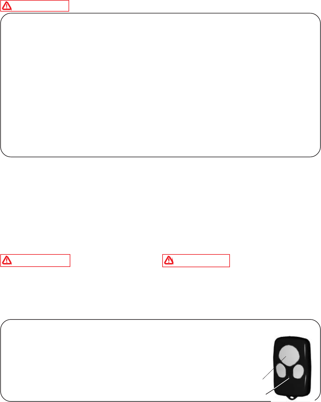
Operation:
Momentarily pressing the large transmitter button, or the button programmed in the transmitter
programming step, activates the door. Other buttons can also be programmed to activate
different doors, for multi-door installations. Each button or a combination of two buttons
pressed simultaneously can be programmed to activate a different door. Only one button at a
time can be programmed to activate a specific opener. The transmitter LED will light while
any transmitter button remains pressed.
NOTE: Refer to Step 30 for transmitter programming instructions.
WARNING TO REDUCE THE RISK OF SEVERE OR FATAL INJURY:
1. READ AND FOLLOW ALL INSTRUCTIONS.
2. Never let children operate or play with the door controls. Keep remote controls away from children.
3. Always keep a moving door in sight and away from people and objects until it is completely closed. NO
ONE SHOULD CROSS THE PATH OF A MOVING DOOR.
4. NEVER GO UNDER A STOPPED, PARTIALLY OPEN DOOR.
5. Test the door opener monthly. The garage door MUST reverse on contact with a 1-1/2 inch high object (or
a 2 x 4 board laid flat) on the floor. After adjusting the limit of travel or profiling (install routine) retest the
door. Failure to adjust the opener properly may cause severe or fatal injury.
6. When possible, use the emergency disconnect only when the door is in the closed position. Use caution
when using the emergency disconnect when the door is open. Weak or broken spring(s) may allow the door to
fall rapidly, causing a severe or fatal injury.
7. KEEP THE GARAGE DOOR PROPERLY BALANCED. See the owner’s manual included with the door.
An improperly balanced door could cause a severe or fatal injury. Have a qualified service person make
repairs to the cables, spring assemblies, and other hardware.
8. SAVE THESE INSTRUCTIONS
Door activation: Upon activation by either the wall station up/down button or transmitter, the door will move in
the following manner:
1. If closed, the door will open. If open, the door will close.
2. If closing, the door will stop, reverse, and return to the open position. Next activation will close the door.
3. If opening, the door will stop. Next activation will close the door.
4. If an obstruction is encountered or an out-of-balance condition is detected while the door is closing, the door
will reverse, return to the open position, and the opener will beep (3) or (4) times. The next activation will close the
door.
5. If an obstruction is encountered or an out-of-balance condition is detected while opening the door, the door will
stop. The next activation will close the door.
6. When door is in motion any button on the wall station functions the same as the up/down button.
WARNING NEVER LET CHILDREN
OPERATE OR PLAY WITH THE DOOR CONTROLS.
KEEP REMOTE CONTROLS AWAY FROM
CHILDREN. FATAL INJURY COULD RESULT
SHOULD A CHILD BECOME TRAPPED BETWEEN
THE DOOR AND THE FLOOR.
WARNING ALWAYS KEEP A MOVING
DOOR IN SIGHT AND KEEP PEOPLE AND
OBJECTS AWAY UNTIL IT IS COMPLETELY
CLOSED. TO PREVENT A SEVERE OR FATAL
INJURY, AVOID STANDING IN A OPEN DOOR
WAY OR WALKING THROUGH THE DOORWAY
WHILE THE DOOR IS MOVING.
31
Important Safety Instructions
Transmitter Operation:
LARGE
BUTTON
LED
32
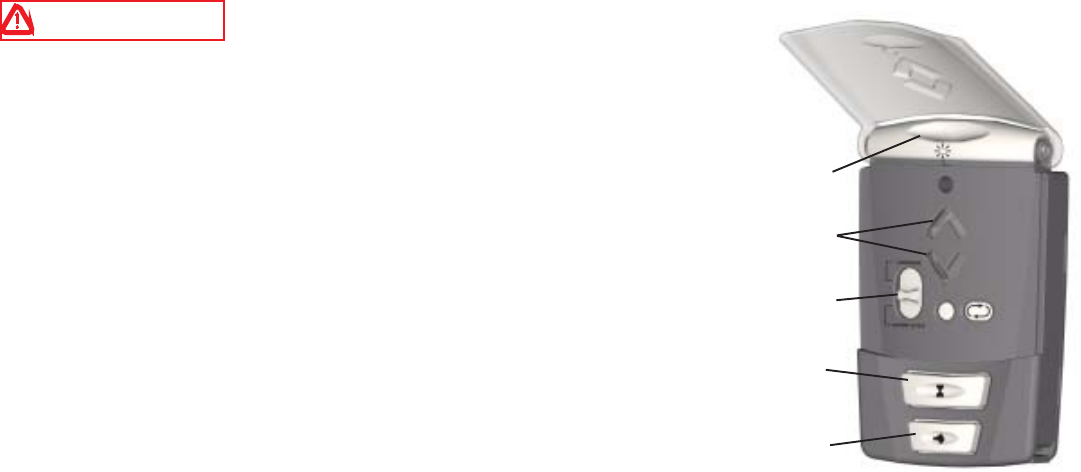
HOW TO OPERATE THE WIRLESS WALL STATION (IF INCLUDED)
WARNING TO PREVENT POSSIBLE INJURY, NEVER LET
CHILDREN OPERATE OR PLAY WITH DOOR CONTROLS. KEEP
REMOTE CONTROL AWAY FROM CHILDREN.
1. Momentarily pressing the Up/Down button starts or stops door
movement or changes door’s direction. Press and hold Up/Down button
during the door’s complete downward travel to override photo eye safety
sensors.
2. Momentarily pressing the Light button turns on the opener’s light or
the light fixture. The light will remain on until either the Light button is
pressed again or the door is activated. The light automatically turns on
with a door activation and remains on for five minutes thereafter.
Pressing the Light button before the five minutes has elapsed will turn
off the light fixture. While the door is in motion, the Light button
functions identical to the Up/Down button, stopping or reversing the
door immediately.
3. Momentarily pressing the Timer button causes a delayed activation of a stationary fully open door. The light
fixture or the opener’s lamp will blink on and off for about 10 seconds prior to closing the door, allowing
enough time to exit the garage when the opener is in the timer mode. Pressing any button, except for the Profile
button while the opener is beeping or the lamp is blinking cancels the timer mode.
NOTE: The timer feature will only function with the door in the full open position. Pressing the Timer
button with a stationary door in any other position will cause the opener lamp to blink four times, but the
door will not be activated.
While the door is in motion, the Timer button functions identical to the Up/Down button, stopping or reversing
the door immediately.
4. Pressing the Pet button opens a closed door to a preset position between eight and thirty inches above the
floor, allowing pets to enter and exit the garage without the door being fully open. The door must be fully closed
to activate the pet open feature. Pressing the Pet button with a stationary door in the pet open position will cause
the door to close. Pressing the Up/Down button while the door is in the pet position will cause the door to open.
While the door is in motion, the Pet button functions identically to the Up/Down button, stopping or reversing
the door immediately. The pet feature allows for custom setting of the pet position door height. Refer to the
opener’s manual for complete Pet button instructions and programming.
NOTICE: A door in the “pet position” (open 8-30 inches) is not locked and should not be considered to be
in a secured door position.
5. The slide switch has two positions: Normal, and Door lock (Disable RF).
5a. Move the slide switch to Normal position for all normal functions of the opener. The Normal position will
cancel the Auto-Close feature and the Door Lock feature.
NOTE: Keep the slide switch in the Normal position unless you have fully read and understood the Door
Lock setting operations and you desire to use one of those settings.
If the door is moving when the slide switch is moved to the Door Lock position, the vacation mode is not
activated and all functions of the opener remain active.
LIGHT
BUTTON
UP/DOWN
BUTTON
SLIDE
BUTTON
TIMER
BUTTON
PET
BUTTON
WARNING KEEP THE GARAGE DOOR PROPERLY BALANCED. AN IMPROPERLY BALANCED
DOOR COULD CAUSE A SEVERE INJURY. HAVE A QUALIFIED SERVICE PERSON MAKE REPAIRS TO
CABLES, SPRING ASSEMBLIES, AND OTHER HARDWARE.
WARNING THE EMERGENCY DISCONNECT SHOULD ONLY BE USED WHEN THE DOOR IS
CLOSED. USE EXTREME CAUTION IF OPERATING THE EMERGENCY DISCONNECT ON AN OPEN
DOOR. WEAK OR BROKEN SPRING(S) MAY ALLOW THE DOOR TO FALL RAPIDLY, CAUSING A
SEVERE OR FATAL INJURY.
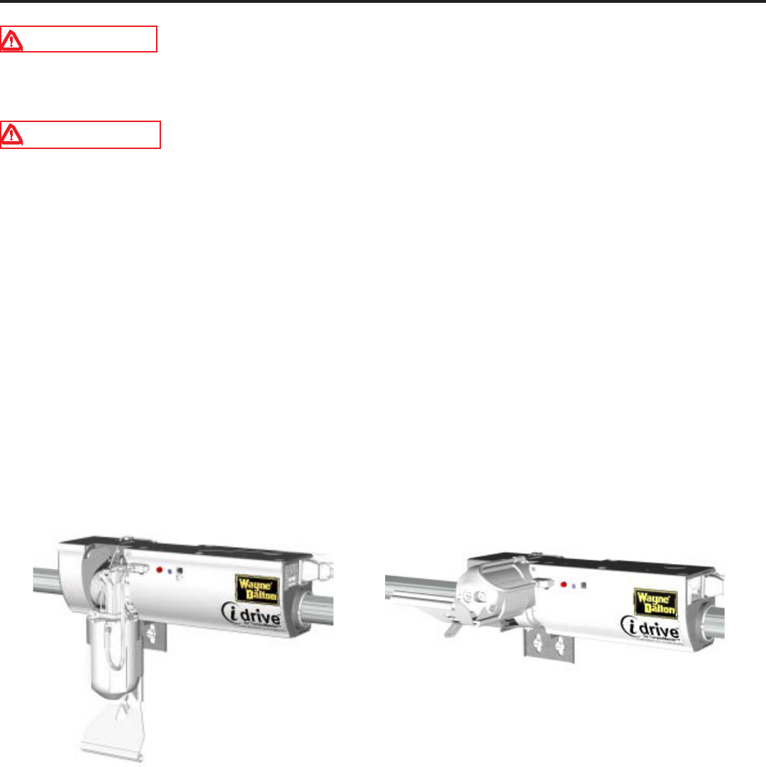
The opener is equipped with an emergency disconnect that allows the door to be moved manually and independent
from the opener.
With the door closed, pull down on the disconnect handle and place the handle under the lower section of the
handle bracket. This motion causes the motor on the opener to pivot upwards and the opener to disconnect from
the torque tube.
Releasing the disconnect handle from the lower section on the handle bracket and returning the handle to its
original position will reconnect the opener to the torque tube.
NOTE: The motor will not pivot down completely when the handle is released. After one motorized up/
down door cycle, the motor will once again pivot down, and all cable slack will be taken up. The garage
door is not locked, secure from forced entry, until the motor is back in the down position.
DISCONNECTED, MOTOR UP POSITION
33
Manual Door Operation Emergency Disconnect:
MOTOR DOWN POSITION (DOOR LOCKED)
6. The Up/Down button backlit red LEDs blink intermittently often to help you locate the wall station in a dark
garage. This blink rate can be changed for longer battery life or can be turned off. The default blink rate is one
blink every 1/2 second.
NOTE: The wall station’s Up/Down arrow LEDs will light while any wall station button remains pressed.
6a. For longer battery life the blink rate can be changed to blink once every second. To change the blink rate,
remove the battery cover and remove one battery. Re-install the battery and within 2 seconds, press the Light
button. Re-install the battery cover.
6b. For longest battery life, the blink can be turned off. To turn off the blink, remove the battery cover and
remove one battery. Re-install the battery and within 2 seconds, press the Pet button. Re-install the battery
cover.
34
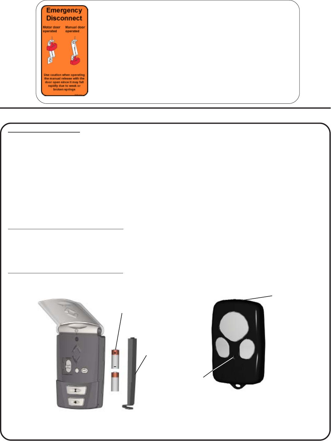
Maintenance:
NOTE: Some transmitters use two CR2016
or equivalent batteries while others use a
single MN21 or equivalent battery.
NOTE: Use only two AAA
batteries.
Monthly Maintenance:
1. With door fully closed, manually operate the door with the emergency disconnect in the manual door
operated position. If the door feels unbalanced or binds, have a qualified service person repair or make
adjustments to the door.
2. Perform the contact/obstruction tests. See Step 29 for the contact/obstruction test instructions. Inability to
activate a door using the transmitter or wall station may be caused by a weak or dead battery. Press and hold
the activation button on either the transmitter or the wall station. If the LED does not light, this is an indication
that the battery is weak or dead. Replace the battery.
NOTE: Dispose of dead batteries properly.
Battery replacement for wall station:
Remove the battery cover completely (right-hand side of wall station) by disengaging the battery cover’s
lower clip. Install two AAA batteries into the wall station observing the polarity, (+) and (-), of both batteries.
After about five seconds, the Up/Down red LEDs will begin to blink momentarily every 1/2 second. Re-install
the battery cover by first inserting its top into the wall station then inserting and securing its bottom.
Battery replacement for transmitter:
Insert acoin in the coin slot of the transmitter and twist coin to access the dead battery. Replace the battery,
being careful to match the positive (+) symbols on the circuit boards with the battery.
Disconnect Label: The label is located next to the disconnect handle.
The adjacent view shows the handle in both the motor operated and
manual operated positions. View on the left side of the label shows the
handle position when the opener is engaged to the torque tube. The
view on the right side of the label shows the handle when the opener is
disconnected from the torque tube.
NOTE: Use extreme caution if disconnecting. The emergency
disconnect should not be used when the door is in the open position.
Weak or broken spring(s) may allow the door to fall rapidly causing a
severe or fatal injury.
COIN SLOT
LED
BATTERY
COVER
Two AAA
BATTERIES
35
Cut template to aid in Wall-station Installation:
DRILLING TEMPLATE FOR MULTI-FUNCTION WALL STATION

Troubleshooting
MOTPMYSESUACELBABORPNOITCAEVITCERROC
llawehtotdnopsertonseodrenepO ?rettimsnartronoitats
.renepoehtotrewopoN
.demargorptoneraslortnoC
teltuoot
drocrewoprenepoehtkcehC .noitcennoc
gnimmargorpdnaegnahcedoceeS .noitces
tontubnoitatsllawehtmorfskrowren
epO ?rettimsnarteht
.demmargorptonsirettimsnarT
.yrettabnoiatsllawdaedrokaeW
gnimmargorpdnaegnahcedoceeS .
noitces
yrettabrofnoitcesecnanetniameeS .tnemecalper
tontubrettimsnartehtmorfskrowrenepO ?noitatsllawehtm
orf .demmargorptonsinoitatsllaW
.yrettabnoitatsllawdaedrokaeW
gnimmargorpdnaegnahcedoceeS .noitces
yrettab
rofnoitcesecnanetniameeS .tnemecalper
speebrenepoehtdnaevomtonseodrooD ?semitowt .demrofrepneebtonsahenit
uorllatsniehT.enituorllatsniehtmrofreP
etomerehthtiwevomtonseodrooD morfemocspeebondnadnammoclortnoc ?ren
epoeht
lortnocetomerahtiwevomtonseodrooD ?emitenospeebrenepodnadnammoc
.rekaerbtiucricdeppirtroesufnwolB
.renepoehtotrewopoN
.gniriwrotomotdegamadelbissoP
atcatnocrorekaerbtiucricehtteseR esufrofnosrepecivresd
eifilauq .noitamrofni
.noitcennocdrocrewopkcehC
.nosrepecivresdeifilauqallaC
renepoehtdna,sesreverrospots
rooD ?semitruofroeerhtspeeb
.deretnuocnenoitcurtsbO
.detcetednoitidnocecnalab-fo-tuO
.htaproodehtraelC
.no
srepecivresdeifilauqatcatnoC
?ylreporpesolctonseodrooD ehtnotoneraselbacecnalabretnuoC .ylreporpsmurd lla
wehtoterusserptnatsnocylppA .roodehtesolcotnottubnwod/pus'noitats
?esolctonlliwrooD
thgiedelcycsahroodeh
T:yaledlamrehT .doirepetunimevifanisemit
.eruliaftsetnoitcurtsbotcatnoC
etunim-enoaretfaetarepolliwrooD .
doirepgnitiaw
atcatnocroenituorllatsniehttaepeR .nosrepecivresdeifilauq
llufronepollufaotlevarttonseodro
oD ?noitisopesolc
.ecnalabfotuosirooD
.ylreporpmiteserastimilrooD
.nosrepecivresdeifilauqallaC
.enituorlla
tsniehttaepeR
?roolfehtotngilatonsirooD .hgihottessitimilroodmottoB
roodehtecrofdnarenepoehttcennocsiD .e
buteuqrotehtgnitatorybroolfehtot ehtetavitcadnarenepoehttcennoceR .enituorllatsni
?roolfehtraenrotagnisr
eversirooD
siroodnehwyllufputoviptonseodrotoM ?gninepo
hcumotevahsgnirpsecnalabretnuoC .noisnet
.nosrepeci
vresdeifilauqallaC
.nurerebotevahyamenituorllatsnI
?roolfehtraenrotagnisreversirooD
ehttsniagathgitootsi
laesroodedistuO .roodehtfoecaf
ehtotesolcotdecapssikcartlacitreV otroodehtgnisuac,noitcesroodmottob .dnib
ostonebotsaoslaesroodehtllatsnieR .roodehtfoecafehttsniagathgit
.nosrepecivresdeifilauqatcatnaC
36

Lock Arm Troubleshooting
MOTPMYSESUACELBABORPNOITCAEVITCERROC
roodehtgnirudthgiltonlliwerutxifthgiL noitatsllawehtgnisserpybronoitarepo ?nottubthgil
ehtoterutxifthgil
ehtfotnemngilasiM .renepo
.renepo&thgilneewtebnoitcurtsbO
.revocrenepoybdekcolbDELgnidneS
reviecerehtfotn
emngilaerutxifthgiltsujdA ehtnoDELgnidnesehthtiweludom .renepo
.noitcurtsboevomeR
revochguorhtedurtorpotD
ELnoitisopeR .eloh
ehtgnisunehwpuylluflluptonseodrotoM ?tcennocsidycnegreme foedisnideppilssahelbactcenno
csiD .eldnah .21petSnisnoitcurtsnirepeldnahllatsni-eR
?evomtonlliwroodehttubstratsrotoM euqrotehtmorfdetc
ennocsidsirenepO .ebut
rotom"ehtnisieldnahtcennocsiderusnE .noitisop"detarepo
.21petSnistnoicurtsnirepeld
nahllatsni-eR
?nwodtoviptonseodrotoM
?sesolcroodehtretfayllaitrapstoviprotoM .drahoottessiniptneteD
niptn
etedehtetator,revirdwercsagnisU litnustnemercninrut4/1niesiwkcolcretnuoc roodehtretfanwodstovipyllufrot
omeht .52petsotrefeR.sesolc
ehterofeb(ylerutamerpnwodstoviprotoM ?)yletelpmocsesolcrood .tfosoottessinipt
neteD
niptnetedetator,reviridwercsagnisU rotomlitnu;stnemercninrut4/1niesiwkcolc dna,sesolcroodretfanwod
stovipylluf .52petseeS.ffostuhsyletaidemmirenepo
Troubleshooting (continued...)
MOTPMYSESUACELBABORPNOITCAEVITCERROC
nehwkcolehthtiwserefretniroodehT .ecnaraelcgniyfirevyllaunam
renepoeh
totdetnuomsimrakcoL .yltcerrocni
.leveltonsiebuteuqrotehT
kcartro/dnastekcarbpotroodehT .yltcerroctestone
ranoitarugifnoc
niptnetedotpudetatorylluftonrotoM .noitisopdegagne
gnisudetnuomsimrakcolehterusnE petSnid
etatsnoitacolelohtcerroceht .launamsihtfo62
dna11spetsreprenepoehttnuomeR renepoehtgnirusne,launamsihtfo
12 otriorpleveleraebuteuqrotdna .gninetsaf
,snoitallatsnirenepodnaroodwenroF dedulcnisnoitcurtsniehtotkca
brefer ro/dnatekcarbpotrofroodehthtiw .snoitarugifnockcart
tnerrucnosnoitallatsnitif-orterroF ,teehstresn
iehtotkcabrefer,srood tifoteR:deltitlaunamsihthtiwdeulcni tekcarbpotrof,evirdirofnoitallatsni .snoitarug
ifnockcartro/dna
dnaeldnahtcennocsidehttnuomeR ,launamsihtfo21petSreptekcarb neewtebnoisnetelbacreporpgn
irusne .eldnahehtdnarenepoeht
37

The Manufacturer warrants that the idrive™ garage door opener will be free from defects in materials and
workmanship including electronic components for a period of FIVE YEARS from the date of installation, provided
it is properly installed, maintained and cared for under specified use and service. The motor has an extended
LIFETIME warranty against defects in materials and workmanship.
This Warranty extends to the original homeowner, providing the garage door opener is installed in his/her place of
primary residence. It is not transferable. The warranty applies to residential property only and is not valid on
commercial or rental property.
NO EMPLOYEE, DISTRIBUTOR, OR REPRESENTATIVE IS AUTHORIZED TO CHANGE THE
FOREGOING WARRANTIES IN ANY WAY OR GRANT ANY OTHER WARRANTY ON BEHALF OF
MANUFACTURER.
The Manufacturer shall not be responsible for any damage resulting to or caused by its products by reason of
installation, improper storage, unauthorized service, alteration of products, neglect or abuse, any acts of nature
beyond Manufacturer’s control (such as, but not limited to, lightning, surges, water damage, etc.), or attempt to use
the products for other than the customary usage or for their intended purposes. The above warranty does not cover
normal wear or any damage beyond Manufacturer’s control or replacement labor.
THIS WARRANTY COVERS A CONSUMER PRODUCT AS DEFINED BY THE MAGNUSON-MOSS
WARRANTY ACT. NO WARRANTIES, EXPRESSED OR IMPLIED, (INCLUDING, BUT NOT LIMITED
TO, THE WARRANTY OF MERCHANTABILITY OR FITNESS FOR A PARTICULAR PURPOSE), SHALL
EXTEND BEYOND THE APPLICABLE TIME PERIOD STATED IN BOLD FACE TYPE ABOVE.
Claims for defects in material and workmanship covered by this warranty shall be made in writing to the dealer
from whom the product was purchased within the warranty period. Manufacturer may either send a service
representative or have the product returned to the Manufacturer at Buyer’s expense for inspection. If judged by
Manufacturer to be defective in material or workmanship, the product will be replaced or repaired at the option of
the Manufacturer, free from all charges except authorized transportation and replacement labor.
THE REMEDIES OF BUYER SET FORTH HEREIN ARE EXCLUSIVE AND ARE IN LIEU OF ALL OTHER
REMEDIES, THE LIABILITY OF MANUFACTURER, WHETHER IN CONTACT, TORT, UNDER ANY
WARRANTY OR OTHERWISE, SHALL NOT EXTEND BEYOND ITS OBLIGATION TO REPAIR OR
REPLACE, AT ITS OPTION, ANY PRODUCT OR PART FOUND BY MANUFACTURER TO BE DEFECTIVE
IN MATERIAL OR WORK SHALL NOT BE RESPONSIBLE FOR ANY DIRECT, INDIRECT, SPECIAL OR
CONSEQUENTIAL DAMAGES OF ANY NATURE.
This Warranty gives you specific legal rights and you may have other rights, which may vary from state to state.
However, some states do not allow limitation on how long an implied warranty lasts or the exclusion or limitation
of incidental or consequential damages so the above limitations or exclusions may not apply to you.
LIFETIME LIMITED WARRANTY
38

Questions??
For quick answers and helpful advise, call
Wayne-Dalton Customer Service
(888) 827-3667
Wayne-Dalton Corp. P.O. Box 67 Mt. Hope, OH 44660 1-888-827-3667