Wayne Dalton TID372R2 GARAGE DOOR OPENER W/ RF LIGHT KIT User Manual 03 0263Manual
Wayne Dalton Corporation GARAGE DOOR OPENER W/ RF LIGHT KIT 03 0263Manual
OWNERS MANUAL

5015 B.U. Bowman Drive Buford, GA 30518 USA Voice: 770-831-8048 Fax: 770-831-8598
FCC Part 15
433.92 MHz Transmitter Certification
& 372 MHz Receiver Declaration of Conformity
Test Report
FCC ID: KJ8-TID372R2
FCC Rule Part: 15.231
ACS Report Number: 03-0263-15C231
Manufacturer: Wayne-Dalton Corporation
Equipment Type: RF Controlled Garage Door Opener
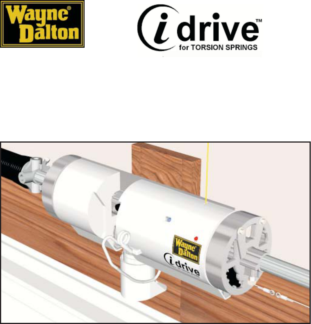
Model: Operator 41XR (Torsion idriveTM)
Model Variants: 3651-372, 3652-372, 3750-372, 3751-372,
3752-372, 3771-372
Installation and Operators Guide
Wayne-Dalton Corp.
P.O. Box 67 Mt. Hope, OH 44660
(888) 827-3667
www.wayne-dalton.com
Models: 3652-372
Covered under one or more of the following U.S. patents:
5,929,580/5,931,212/6,667,591/6,568,454/6,561,256/6,561,255/6,605,910/6,401,792/
6,326,751/6,326,754/6,325,134/6,164,014/6,145,570/6,078,249/D474,215/D473,574/
D473,573/D413,867/D413,579/D413,055/D421,031/D472,568/D472,910
other U.S. and foreign patents pending
Installation Instructions and Owner’s Manual
© Copyright 2003, 2004 Wayne-Dalton Corp. Rev.5 1/30/2004
Part No. 305871
Important Notice!
Read the enclosed instructions carefully before installing/operating this garage
door opener. Pay close attention to all warning labels and notes. This manual
should be attached to the wall in close proximity to the garage door opener.
PRELIMINARYPRELIMINARY
PRELIMINARYPRELIMINARY
PRELIMINARY
1/30/20041/30/2004
1/30/20041/30/2004
1/30/2004

Table of Contents
Important Safety Instructions 3.
Package Contents 4.
Tools Needed 5.
Available Accessories 5.
Pre-Installation Inspection 6.
Torsion idrive Installation 7. - 12.
Pre-Operation Installation 13. - 25.
Operation 26. - 29.
Maintenance 30.
Troubleshooting 31. - 32.
Warranty 32.
Customer Service Number 33.
After installation is complete, fasten this manual near garage door. Perform monthly
maintenance (see Maintenance section page 30) and periodic checks, as
recommended.
NOTE: This equipment has been tested and found to comply with limits for a Class B digital device,
pursuant to Part 15 of FCC Rules. These limits are designed to provide reasonable protection against
harmful interference in a residential installation. This equipment generates, uses and can radiate radio
frequency energy and, if not installed and used in accordance with these instructions, may cause harmful
interference to radio communication; however, there is no guarantee that interference will not occur in a
particular installation. If this equipment does cause harmful interference to radio or television reception,
which can be determined by turning equipment off and on, user is encouraged to try to correct interference
by one or more of the following measures: Reorient or relocate receiving antenna. Increase separation
between equipment and receiver. Connect equipment into an outlet on a circuit different from that which
receiver is connected. Consult your dealer or/and experienced radio/television technician for help.
WARNING: Changes or modifications to this unit not expressly approved by party responsible for
compliance could void user’s authority to operate this equipment.
FCC and IC Statement
FCC Regulatory Information:
This device complies with Part 15 of the FCC Rules. Operation is subject to the following two
conditions: (1) this device may not cause harmful interference, and (2) this device must accept any
interference received, including interference that may cause undesired operation.
IC Regulatory Information:
Operation is subject to the following two conditions: (1) this device may not cause interference, and
(2) this device must accept any interference, including interference that may cause undesired
operation of the device.
2
3
IMPORTANT SAFETY INSTRUCTIONS FOR
INSTALLATION AND USE
IMPORTANT SAFETY INSTRUCTIONS FOR
INSTALLATION AND USE
READ AND FOLLOW ALL
INSTALLATION INSTRUCTIONS.
Do not connect the opener power
head to a power source until
instructed to do so.
Where possible, install the opener
power head seven feet or more
above the floor. For products
requiring an emergency release,
mount emergency release six feet
above the floor.
Locate the wall station: (a) within
sight of door, (b) at a minimum
height of five feet, so small children
cannot reach it, and (c) away from all
moving parts of the door.
After installing the opener, the door
must reverse when it contacts a
1- 1/2” high object (or 2 x 4 board
laid flat) on the floor.
WARNING: INCORRECT
INSTALLATION CAN LEAD
TO SEVERE OR FATAL
INJURY. FOLLOW
INSTRUCTIONS.
WARNING: IT IS VITAL FOR
THE SAFETY OF PERSONS TO
FOLLOW ALL INSTRUCTIONS.
SAVE THESE INSTRUCTIONS
.
Install the entrapment warning label
next to the wall station in a
prominent location. For products
requiring an emergency disconnect,
install the emergency release
marking on or next to the emergency
disconnect.
Remove all ropes and remove or
make inoperative all locks
connected to the garage door before
installing the opener.
Do not wear rings, watches or loose
clothing when installing or servicing
a garage door system.
Install only on a properly installed
garage door. An improperly
balanced door could cause severe
injury. Have a qualified service
person make repairs to cables,
spring assemblies, and other
hardware before installing the
opener.
Installation and wiring must comply
with local building and electrical
codes. Connect power cord to a
properly grounded outlet. Do not
remove the ground pin from power
cord.
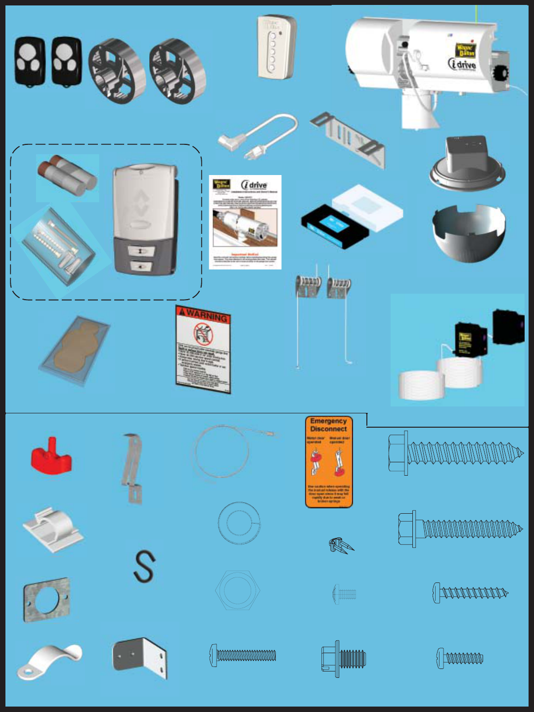
Hardware Kit:
4
Package Contents:
Cable Keeper
Assemblies W/ Hardware (2)
(Right and Left)
Installation Video
6’ Power Cord
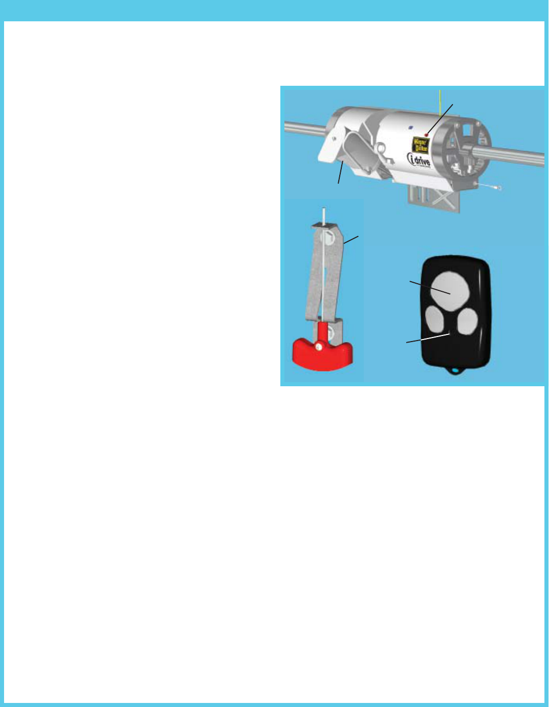
Opener
Three-button
Transmitter (2)
Light Fixture Assembly w/
Diffuser
Entrapment Label
Multi-Function
Wall Station Assembly
Disconnect
Handle (1)
Handle Bracket (1)
“S” Hook (1)
Disconnect Cable (1)
Disconnect Cable
Guide Bracket
Emergency
Disconnect Label (1)
Hardwire Plate
5/16 x 1-5/8” Hex Head Lag
Screws (2)
1/4 x 1-1/2” Hex Head Lag
Screws (4)
5/16 lock Washer (2)
1/4-20 x 3/8” Tapping
Screw (4)
#6-20 x 1/2”
Plastifast Screw (1)
5/16-18 Nut (2) #6 x 7/8” Phillips Pan
Head Screws (4)
Power Cord Clip
(adhesive back) (1)
Cable Clips (4)
Grease Packet (1)
Owners
Manual
Photoelectric Safety Sensors
W/Hardware
#6-25 x 1/4”
Self Tapping Screw (2)
Gear Assemblies (2)
Insulated
Staples (12)
5 Button Wireless Keyless Entry
(KEP3) W/ Hardware
Mounting Bracket
#6-32 x 3/4” Phillips
Pan Head Screw (1)
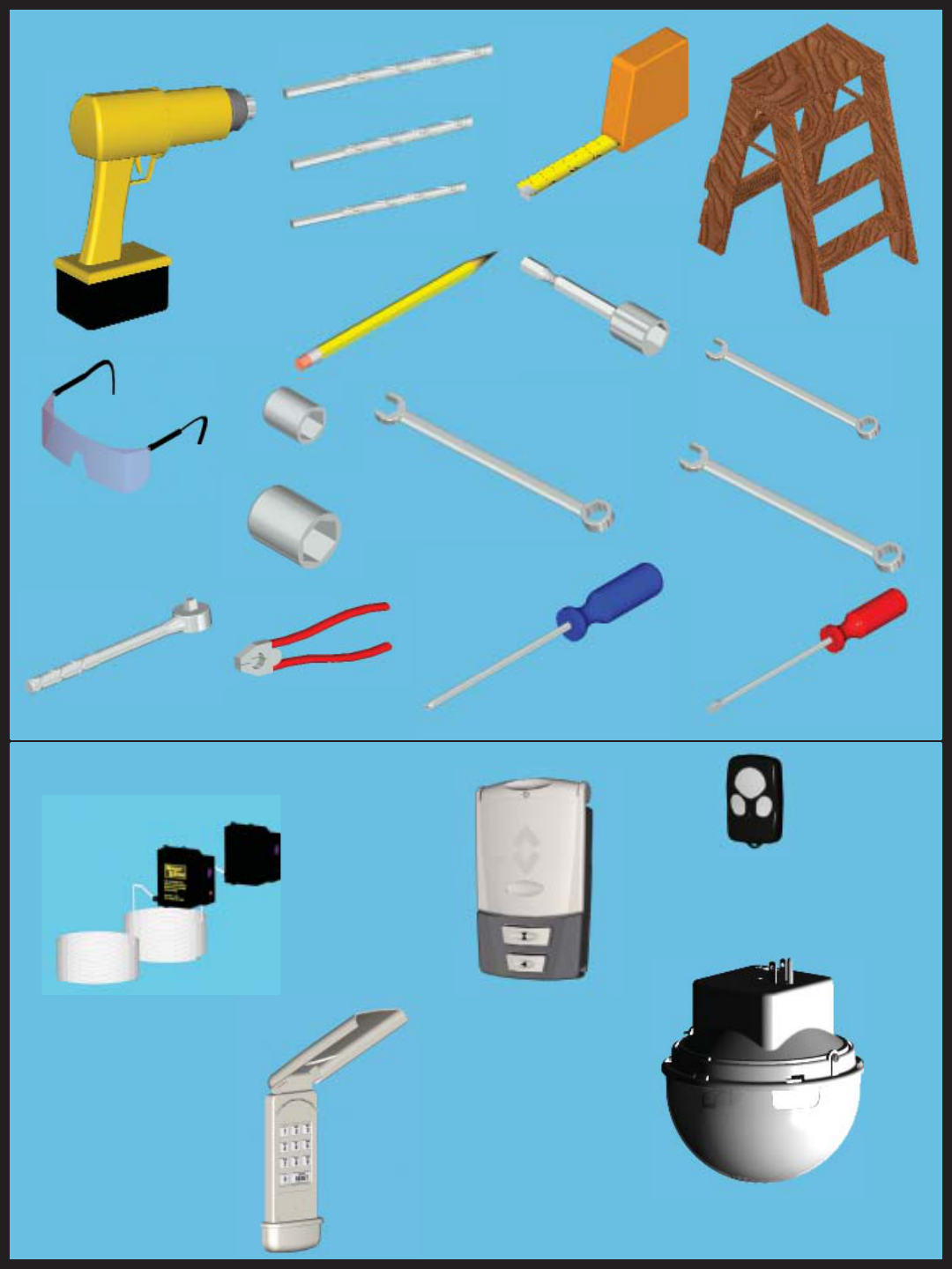
Tools Needed:
5
Available Accessories:
Infrared Safety Sensor
Model no: 3967
Part no: 252118
Multi-Function
Wall-station RF Transmitter
Model no: 3977
Part no: XXXXXX
Power Drill
Safety Glasses
Tape Measure
Step Ladder
9/16” Wrench
Phillips Head
Screwdriver
7/16” Socket Driver
3/32” Drill Bit
Pencil
Flat Head
Screwdriver
1/8” Drill Bit
Ratchet
7/16” Socket
3/16” Drill Bit
Pliers/Wire Cutter
9/16” Socket
7/16” Wrench
3/8” Wrench
3-Button Mini RF
Transmitter
Model no: 3973
Part no: 302083
Keyless Entry RF
Transmitter
Model no: KEP2
Part no: 302078 Deluxe Wireless Light Kit
Model no: 3951-ULD
Part no: XXXXXX
6
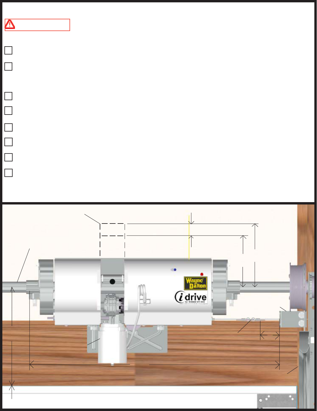
Pre-Installation Inspection
See the illustration below for the dimensions required for the Torsion idrive™ Garage Door Opener.
CAUTION DO NOT INSTALL THIS OPENER ON YOUR DOOR
UNLESS THE FOLLOWING ITEMS ARE MET.
LOCK ADJUSTMENTS
The torsion tube must be 1” in diameter.
There must be at least 30-3/8" of clear torsion tube between the right (inside garage looking out) cable
drum and the counterbalance spring. When installing idrive, ensure there is at least 6" of clearance between
the “S” hook and the disconnect cable guide bracket.
The motor requires between 3-1/4" to 5" of headroom above the center of the torsion tube.
There must be at least 7.5" of clearance between the top of the door and the center of the torsion tube.
Required distance from the center of the torsion tube to the header (mounting location) must be 2-1/2" to
3-3/8".
Your door must not exceed 8' in height.
Torsion idrive™ will only work on multi-sectional doors. Do not install in one piece doors.
Your Garage Door must be properly balanced (door must not be heavy to lift, nor lift by itself). Maximum
door weight must not exceed 400 lb.
Before installing Torsion idrive™, ensure your door system meets the following requirements. Follow the
illustration below as a visual guide.
TORSION TUBE = 1” DIA.
5”
MAX.
3-1/4”
MIN.
CABLE GUIDE
BRACKET
“S” HOOK
LOCK/MOTOR
TRACK
6”
30-3/8”
CLEARANCE FOR
MOTOR
8’ MAX.
7-1/2”
MIN.
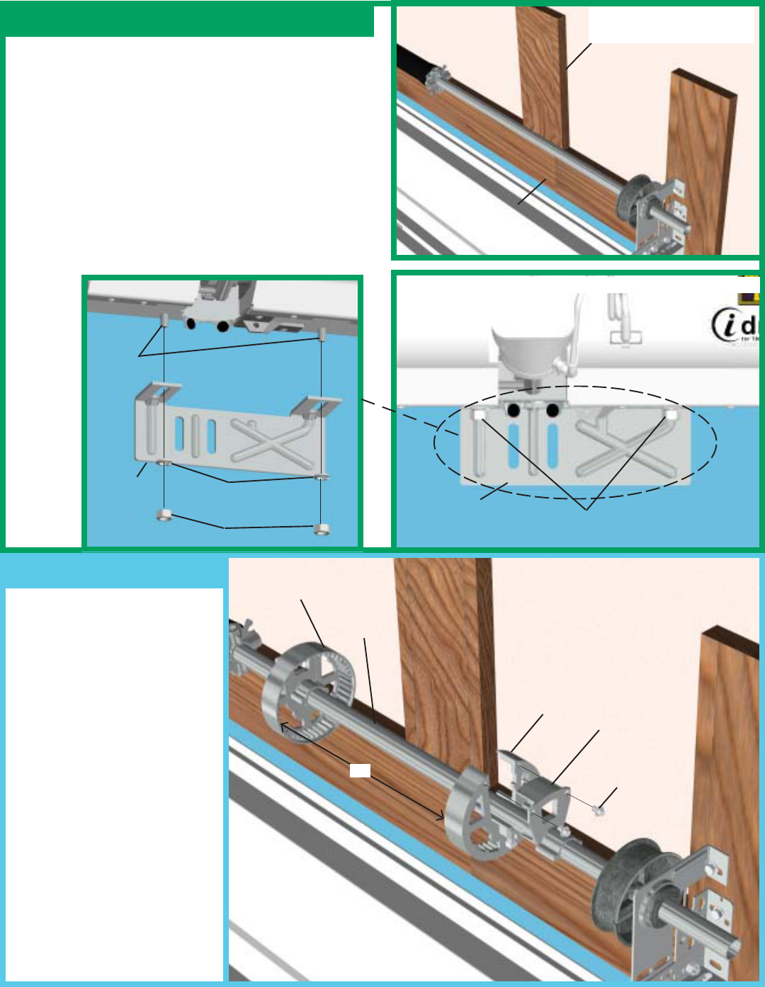
Torsion idrive™ Installation
Locate both gear assemblies.
Remove the bridge gear from
the gear assembly. Place the
main gear onto the torsion tube.
Orient the bridge gear so that it
can slide into position
surrounding the torsion tube.
Ensure that both pieces fit
together properly. Secure the
bridge gear to the main gear
with the (2) 1/4-20 x 3/8"
screws. Repeat procedure with
second gear assembly. Slide the
gear assemblies 19" apart. See
illustration for position of
driven gear assemblies.
7
Step 1
Step 2
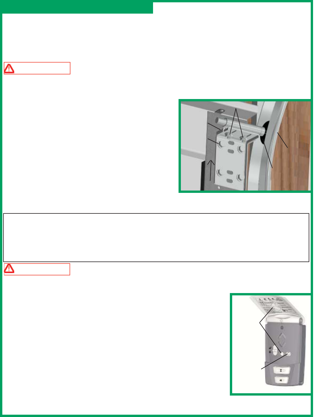
If there are no suitable mounting surfaces to mount the
opener, a strong mounting support will be needed.
Securely fasten a wood (2" x 6" recommended)
mounting surface for the opener. Make sure it is flush
with the header and located to allow the opener to
secure to it. Install the adjustable wall bracket to the
studs in the wall plate. Loosely secure with the 5/16-
18 nuts and lock washers provided.
IMPORTANT! This opener will not install properly
on doors with offsets other than 3-3/8” and 2-1/2”.
BRACKET INSTALLED ON OPENER
BRIDGE
GEAR
GEAR ASSEMBLY
MAIN GEAR
19” 1/4-20 X 3/8”
SCREWS
MOUNTING LOCATION
(2” X 6” RECOMMENDED)
HEADER
TORSION
TUBE
OPENER
WALL
BRACKET 5/16-18 NUTS &
LOCK WASHERS
WALL
BRACKET
STUDS
5/16-18 NUTS
5/16-18
LOCK WASHERS
OPENER

Lubricate both right
hand and left hand gear
assemblies, with the
grease provided. Apply
grease along the torsion
tube where the opener
will mount. Place the
opener over the 1"
torsion tube and between the two gear assemblies. Center
the opener mounting bracket over the mounting support.
Lift the opener slightly and slide the left hand gear
assembly over so that the left hand drive gear meshes
with and rests on the teeth of the left hand gear assembly.
Repeat for right hand gear assembly. Plug motor power
cord into the opener.
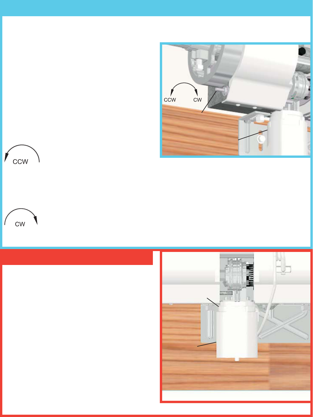
Hand tighten the 3/8” square head bolt on the left hand
gear assembly. Then with a wrench tighten 1 to 1-1/4
turns to set screw. Adjust the opener and left hand gear
assembly so that there is a minimum 1/8" spacing
between the opener and the left hand gear assembly.
Now, adjust the right hand gear assembly, so that there
is a minimum 1/8"
spacing between
opener and the
gear. Tighten the
3/8" square head
bolt in the same
manner as above.
8
Step 3 GREASE
PACKET
Adjust the mounting bracket so that it fits flush with the
header/ mounting support. Tighten the 5/16-18 nuts. Next,
level the opener with the torsion tube and door. Near the
cable drum, measure the distance from the torsion tube to
the top of the door. This dimension must be the same at the
opener point on the torsion tube to the door. Adjust the
opener vertically (if necessary) to accommodate this. Mark
a line under the mounting bracket when the torsion tube
and top of door are parallel. Keeping the mounting bracket
aligned with the line, secure the bracket to the mounting
support by first pre-drilling the lag screw locations with 3/
16” dia. bit and fastening with (2) 5/16” x 1-5/8” lag screws.
Step 5
Step 4
GEAR ASSEMBLIES
1” TORSION
TUBE
1” TORSION
TUBE
OPENER RIGHT HAND
DRIVE GEAR
1/8” 1/8”
OPENER
LEFT HAND
GEAR
ASSEMBLY
RIGHT HAND
GEAR
ASSEMBLY
3/8” SQUARE HEAD BOLT
PLUG IN MOTOR
POWER CORD
GREASE
ALL TEETH
IN GEAR
(2) 5/16” X 1-5/8”
LAG SCREWS MOUNTING
BRACKET
SUPPORT
FOUNDATION
5/16-18 NUTS
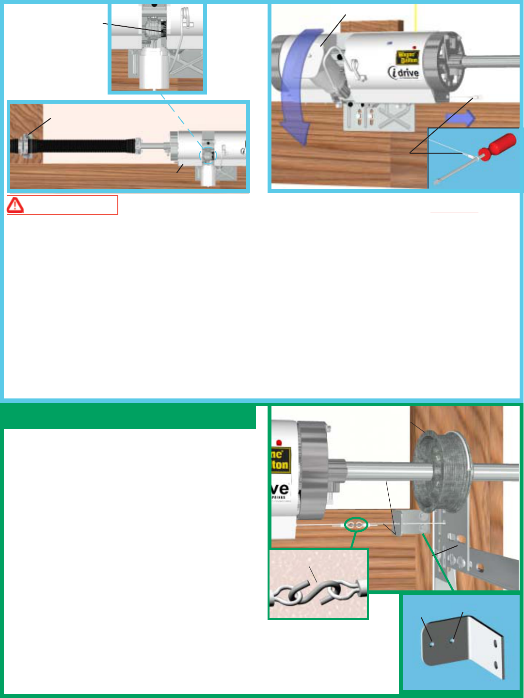
Attach the loose disconnect cable, from the hardware
kit, to the opener disconnect cable using the “S” hook
provided. Close both ends of the “S” hook to lock the
assembly together. Thread the cable guide bracket onto
the disconnect cable making sure that the proper hole
is used. For the 2-5/8" to 2-1/2” tube offset, use the
hole closest to the flange. For the 3-3/8" tube offset,
use the hole farthest from the flange.
NOTE: Depending on the type of door the opener is
being installed onto, it may be necessary to drill a hole
in the right side flagangle for routing the disconnect
cable through.
First locate the flange of the cable guide bracket just
inside the cable drum. Align the cable so that it remains parallel to the torsion tube.
IMPORTANT! If cable is not aligned parallel to the torsion tube, the disconnect
operation will not function properly.
WARNING WHEN LEVELING THE OPENER TO THE TORSION TUBE DO NOT MAKE
ANY ADJUSTMENTS TO THE CENTER SPRING BRACKET ASSEMBLY. REMOVING ANY LAG
SCREWS HOLDING THE SPRING BRACKET TO THE WALL MAY RESULT IN SEVERE OR FATAL
INJURY. LEVEL THE OPENER BY SIMPLY MOVING THE UNIT UP OR DOWN VERTICALLY.
Pull on the disconnect cable that is located at the lower right hand side of the opener. NOTE: The disconnect
cable must be pulled straight out. The disconnect cable cannot be pulled at an angle.
While holding the disconnect cable rotate the motor into the down position. Release the disconnect cable to
allow the disconnect bearing to re-engage the motor assembly.
HELPFUL HINT: Insert a screwdriver through the cable loop, to use as a handle when pulling disconnect
cable.
9
FLAGANGLE
PARALLEL
CABLE DRUM
Step 6
“S” HOOK
CABLE GUIDE BRACKET
2-5/8” TO 2-1/2”
OFFSET
3-3/8”
OFFSET
DISCONNECT CABLE
MOTOR
DISCONNECT
BEARING
(ENGAGED)
CENTER SPRING
BRACKET ASSEMBLY
OPENER
10
Once the cable guide bracket is aligned, secure the
bracket to the jamb, using (2) 1/4 x 1-1/2" lag screws.
NOTE: It is recommended that 1/4" lag screw
locations are pilot drilled using 1/8" drill bit. Disconnect cable must be routed behind the counterbalance
cable and it must not rub on the counterbalance cable. Route cable through the cable guide bracket, behind
the counterbalance cable and through a convenient hole or slot in the flagangle. IMPORTANT! Ensure that
the disconnect cable is between the counterbalance cable and the header/jambs. If there isn’t a hole
available, it may be necessary to drill a 1/8" diameter hole in the flagangle. Route cable through flagangle so
that the disconnect cable is now hanging outside of the track.
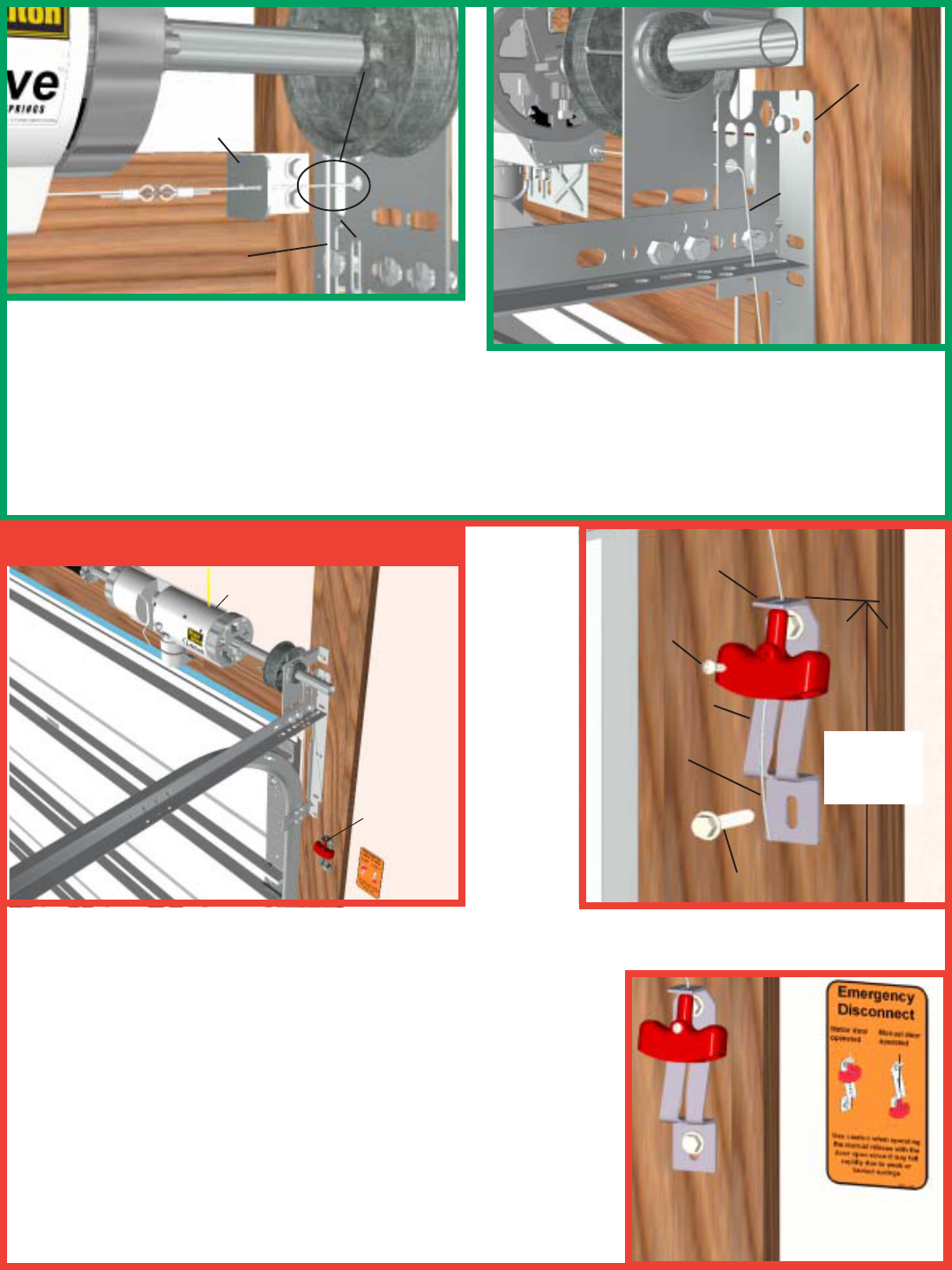
Mark a location on the right jamb, 6 feet above the floor to mount the handle bracket. Align top of the bracket
with the mark. Fasten bracket to the jamb with (2) 1/4 x 1-1/2" lag screws. Start the #6-20 x 1/2"screw into the
handle. Thread the disconnect cable through the top of the handle bracket
and then the handle. Locate the handle in full upper position of handle
bracket. Then remove all cable slack between the opener and the top of
the handle bracket. Tighten #6-20 x 1/2" screw into the handle until
snug, and then tighten screw an additional 1 to 1-1/2 turns to secure
cable to handle. Trim off excess cable from bottom of the handle.
NOTE: It is recommended that 1/4" lag screw location be pilot drilled
using 1/8" drill bit. CAUTION: Pull cable only enough to remove
the cable slack. Pulling the cable more could cause opener to
disconnect from the torsion tube.
Apply emergency disconnect label next to the mounted bracket. Use
mechanical fasteners if adhesive will not adhere.
MOUNTED
BRACKET EMERGENCY
DISCONNECT
LABEL
HANDLE
BRACKET
DISCONNECT
CABLE
#6-20 X 1/2”
SCREW
DISCONNECT
CABLE
FLAGANGLE
CABLE
GUIDE
BRACKET
DISCONNECT CABLE MUST
BE BETWEEN JAMBS/HEADER
AND COUNTERBALANCE
CABLE
HEADER
COUNTER
BALANCE CABLE
FLAGANGLE
1/4” X 1-1/2” LAG SCREW
6’ to
floor
Step 7
OPENER
HANDLE
BRACKET
HANDLE
11
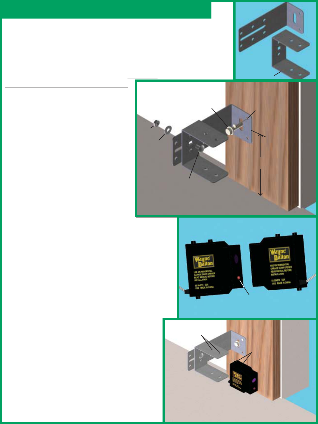
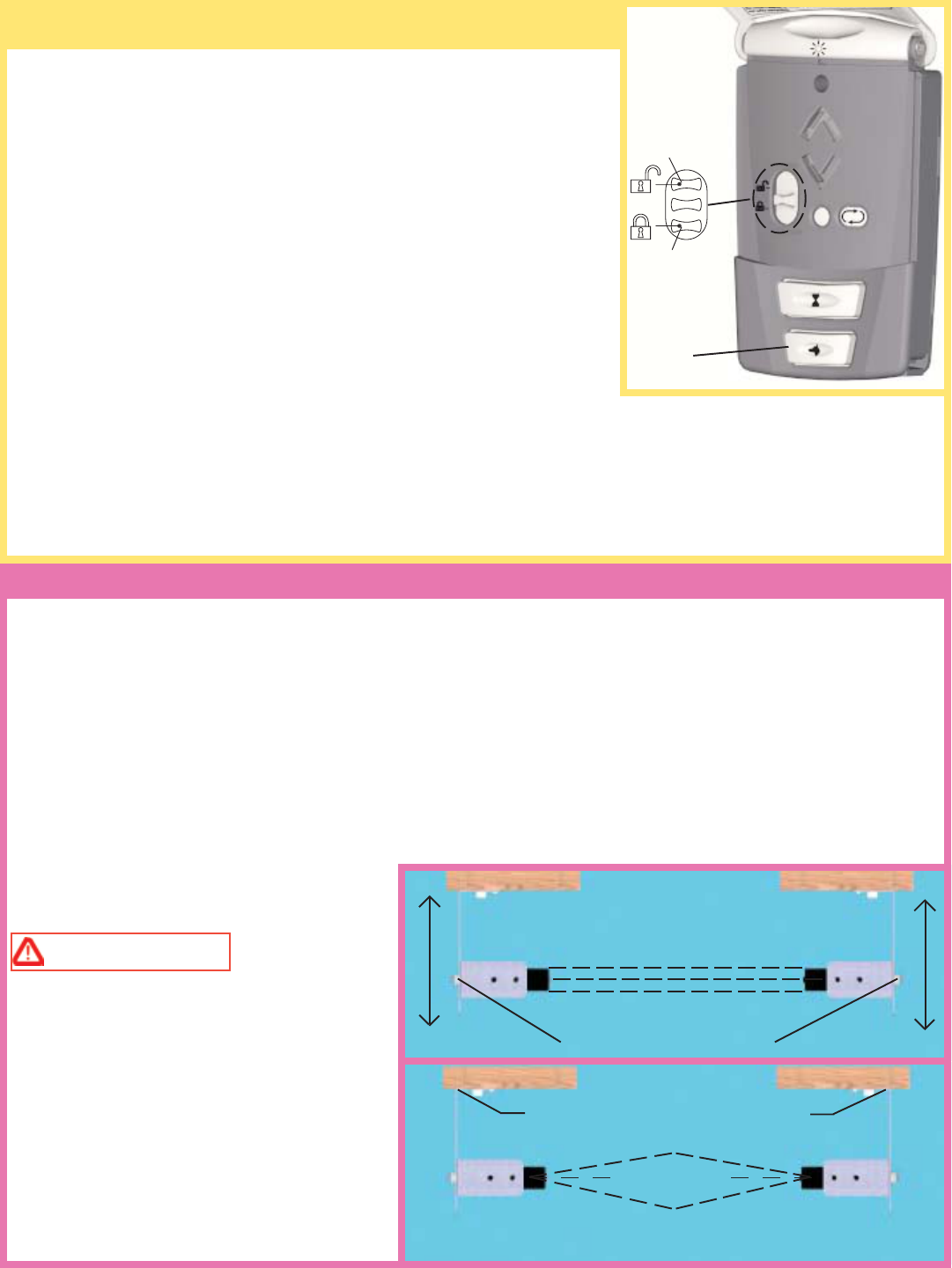
Step 8: Photoelectric Safety Sensor Installation
Select a mounting position no more than 5 inches above
the floor to center line of wall mounting bracket. The
sending and receiving units should be mounted inside
the door opening to minimize any interference by the
sun. However, the sensors should be mounted as close
to the door track or inside edge of the door as possible
to offer maximum entrapment protection. It is very
important that both wall brackets be mounted
at the same height for proper alignment.
The brackets may be temporarily mounted
to the jamb with a 1" flat head nail (provided)
using the small hole above the slot. Using
two 5/16 x 1-1/2" lag screw (provided),
permanently mount the wall mounting
brackets to both door jambs. In some
installation it may be necessary to attach a
wooden spacer to the wall to achieve the
required clearance.
Attach the “U” brackets to the wall brackets
with a 1/4-20 carriage bolt, washer and nut
(provided). Insert the bolt from the inside of
the “U” bracket and hand tighten only, at this time.
Identify which side of the garage door opening (if any)
is “likely” to be exposed to sunlight. Since sunlight may
affect photoelectric sensors, you should mount the
sending unit (not the receiving unit) on the side of the
door opening most exposed to the sun.
NOTE: If wires must be lengthened or spliced into
prewired installation, use wire nuts or suitable
connectors.
Attach the sending and receiving units to the “U”
brackets by inserting their tabs into the respective holes.
WALL
MOUNTING
BRACKET
NUT
WASHER
1/4-20 X 1/2”
CARRIAGE BOLT
(1) 5/16 X 1-1/2”
LAG SCREWS
5”
“U” BRACKET
RECEIVING UNIT
SENDING UNIT
HAS NO LED
LIGHT
LED ALIGNMENT
LIGHT
TABS
TOP & BOTTOM
TAB HOLES
TOP & BOTTOM
NAIL
DOOR
JAMB
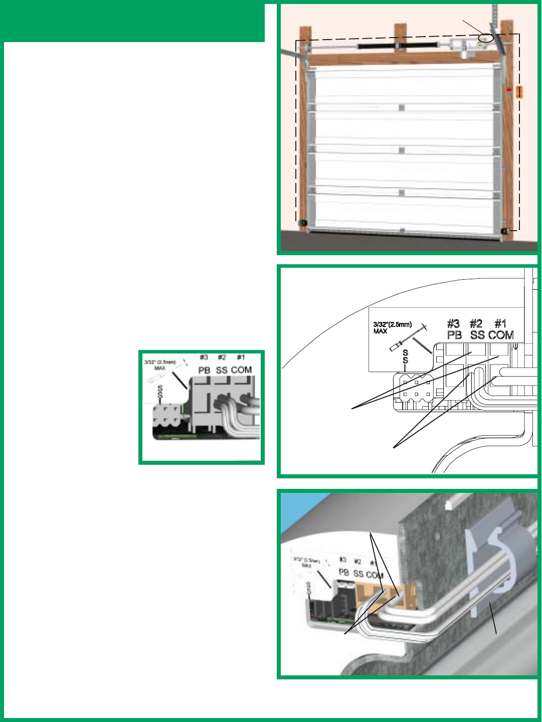
Photoelectric Safety Sensor
Installation Continued
To locate the terminal block for the infrared sensor
sender/receiver wires, you must first move the right hand
gear assembly. Loosen the 3/8” square head bolt (refer
to Step 4.) and slide the gear assembly away from the
opener.
Uncoil wires from photoelectric sensors and route wires
up garage wall and along door header towards the right
side of the opener power head. Route wires behind
torque tube and tack wires in place with insulated
staples.
Connect photoelectric sensors to the opener power head
terminal block on right side of the opener power head.
Separate wire ends and strip about 1/2" of insulation
off each of the wire ends. Insert a 3/32" max. width
flathead screwdriver into the upper hole #1 of terminal
block. Twist screwdriver to open wire clamp in lower
hole #1 of terminal block. Insert both sender and receiver
solid white wires into lower hole #1 until the wires
bottom out and then
release screwdriver
tension. Insert both
sender and receiver wires
(white with black stripe)
into lower hole #2 by the
same process.
Keep the sender and
receiver wires straight
and organized by wrapping them around the backside
of the opener and securing them using the cord clip
(adhesive backed) provided.(Insure the surface the cord
clip is attached to is clean and oil free).
IMPORTANT! Keep sender/receiver wires away from
moving members.
NOTE: Reinstall the right hand gear assembly onto
the drive gear. Ensure that the gear assembly is installed
correctly (refer back to Step 4). Proceed to Step 9.
CORD CLIP
INSERT
SENDER
WIRES
INSERT
RECEIVER
WIRES
RIGHT HAND SIDE
VIEW OF OPENER
INSERT SCREW-
DRIVER INTO
UPPER HOLES
INSERT WIRES INTO
LOWER HOLES
WIRE ROUTING
12
13
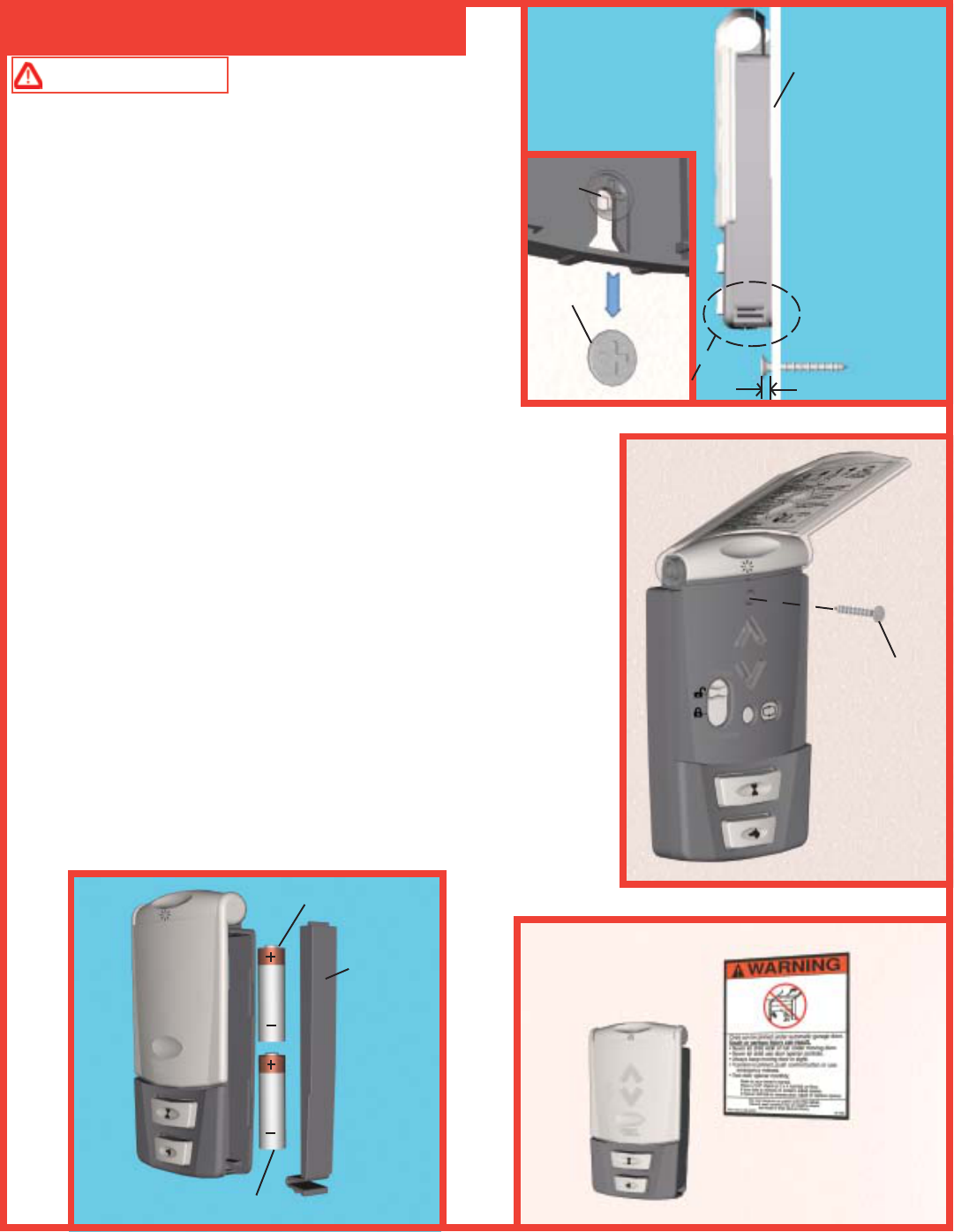
Step 9: Wall Station Installation
Pre-Operation Installation
WARNING TO PREVENT POSSIBLE
INJURY, INSTALL ALL WALL CONTROLS OUT OF
THE REACH OF CHILDREN AND IN A LOCATION
WHERE THE DOOR CAN BE SEEN BEFORE
ACTIVATING. DO NOT MOUNT PUSH BUTTONS
NEAR OR NEXT TO GARAGE DOOR.
Select appropriate place to mount wall station. To keep wall
station out of the reach of children, locate it at least five
feet up from the floor. If possible, install on wood framing.
If fastening into drywall or concrete, use anchors provided.
Using a 3/32" drill bit and the drilling template located on
page 33, drill the two mounting holes. Drill 3/16” holes if
using anchors. Install lower screw leaving 1/8" of the threads exposed.
Slide wall station keyhole slot onto the lower screw. Wall station should
slide onto screw, providing a snug fit. If necessary, remove wall station
and loosen or tighten lower screw. Once wall station is fitted snuggly
on lower screw, install upper screw. Do not over tighten.
CAUTION: Over tightening the upper screw could deform plastic
case.
Battery Installation: Remove the battery cover completely (right-hand
side of wall station) by disengaging the battery cover’s lower clip.
Install two AAA batteries into the wall station observing the polarity,
(+) and (-), of both batteries. After about five seconds, the Up/Down
red LEDs will begin to blink momentarily every 1/2 second. Re-install
the battery cover by first inserting its top into the wall station then
inserting and securing its bottom. Apply entrapment label in convenient
location next to the wall station.
ENTRAPMENT LABEL
BATTERY POLARITY(+ AND -)
BATTERY
COVER
1/8”
WALL
SCREW
KEY
HOLE
SLOT
WALL
SCREW
(2) AAA BATTERIES
1/8”
14
Step 10
SPACER
ROLLER
CABLE KEEPER
ASSEMBLY
1/8” 1/2”
(2) 1/4 X 11/16”
SELF DRILLING
SCREWS
COUNTERBALANCE
CABLE
CABLE KEEPER
ASSEMBLY
(INSTALLED)
BOTTOM
BRACKET
CABLE
KEEPER ARM
PLASTIC
SLEEVE
CABLE
KEEPER ARM
FIG.1
FIG.2
FIG.3
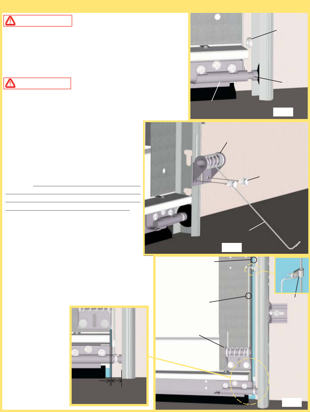
WARNING PRIOR TO INSTALLING CABLE
KEEPERS, CHECK FOR BROKEN OR FRAYED
COUNTERBALANCE CABLES. OPERATING A DOOR
WITH BROKEN OR FRAYED CABLE(S), MAY RESULT
IN A SEVERE OR FATAL INJURY. CONTACT A
QUALIFIED DOOR SERVICE PERSON TO REPLACE
BROKEN OR FRAYED COUNTERBALANCE CABLES.
WARNING DO NOT ATTEMPT TO REMOVE
OR LOOSEN BOTTOM BRACKETS IN ANYWAY. THEY
ARE UNDER EXTREME SPRING TENSION AND CAN
CAUSE SEVERE OR FATAL INJURY.
NOTE: The cable keeper must have a min.
1/2” clearance between the section and vertical
track to function properly.
Push the spacer on to the roller shaft between the
bottom bracket and roller (see fig.1). Use an
additional spacer if needed to achieve min. 1/2”
clearance. If there is less than 1/2” clearance, loosen
the lag screws attaching the track to the wall to
provide additional clearance. After adjusting the track
for the 1/2” clearance re-tighten the lag screws.
IMPORTANT! Right and left hand is always
determined from inside the building looking out.
Attach the right hand (Black) cable keeper assembly
to the bottom section directly above the bottom
bracket (see fig.2). Position the cable keeper assembly
so that it over hangs the edge of the section by 1/8”
(see fig.3). Fasten with (2) 1/4 x 11/16” self drilling
screws (wood doors will use (2) 1/4 x 1” lag screws).
NOTE: It is recommended that wood doors be pre
drilled with an 1/8” pilot hole, prior to fastening.
Repeat for the left hand
side (Red) cable keeper
assembly.
Once the cable keeper
assemblies are secured
to the section, place the
plastic sleeve over the
cable and then rotate the
arm upward and attach
it to the plastic sleeve.
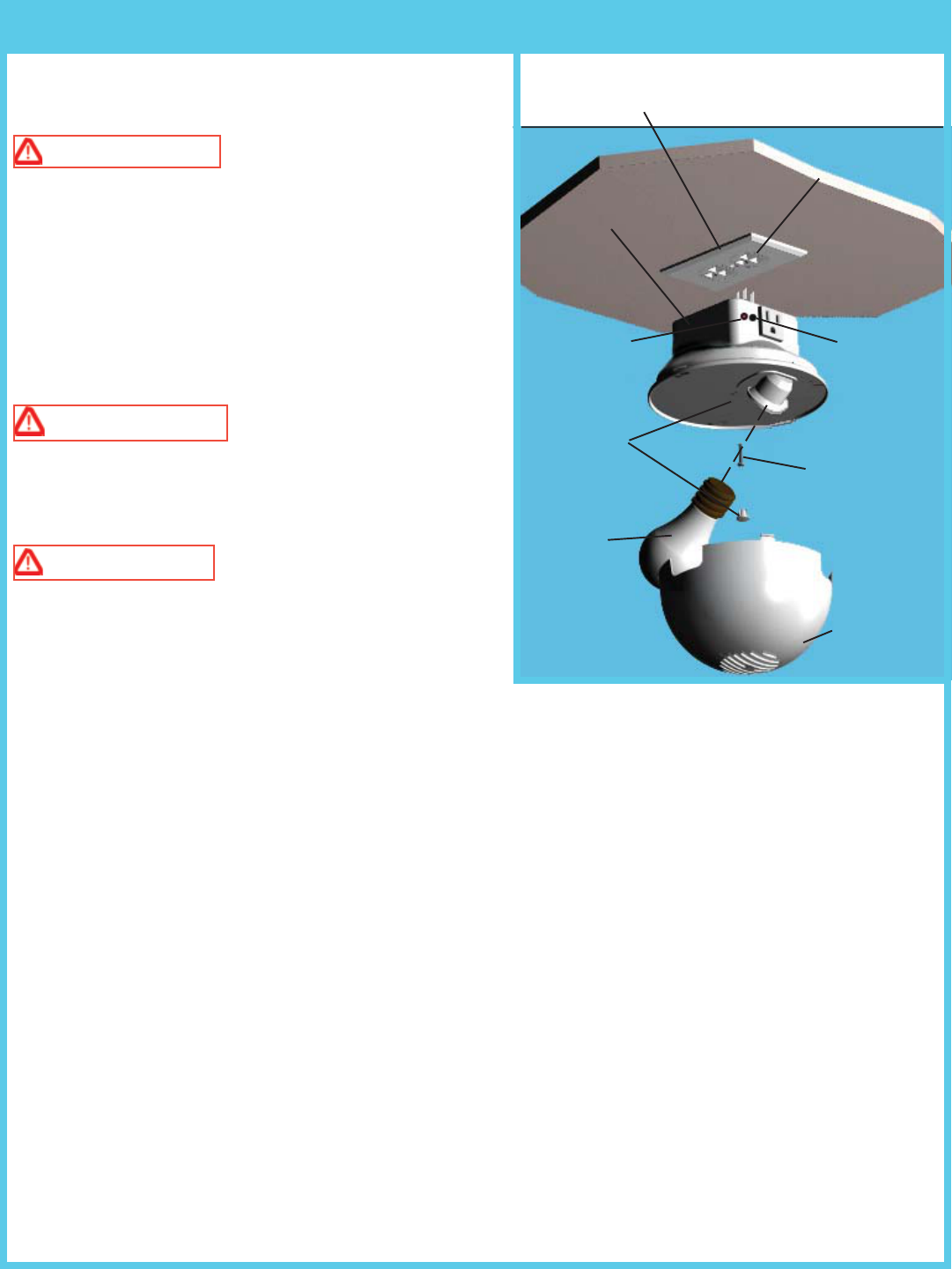
Step 11: Light Fixture Installation
15
NOTE: RECEPTACLE COVER MUST BE IN-
STALLED IN-BETWEEN THE LIGHT FIXTURE AND
THE CEILING
RED
PROGRAM
BUTTON
DUPLEX
RECEPTACLE
LIGHT FIXTURE
DIFFUSER
HOLE PLUG
#6-32 X 3/4”
PHILLIPS
PAN HEAD
SCREW
75W (MAX)
LIGHT BULB
(NOT IN-
CLUDED)
RECIEVER
The light fixture is designed to mount directly to a standard
120V duplex receptacle.
WARNING TO REDUCE THE RISK OF
ELECTRICAL SHOCK, THIS EQUIPMENT HAS A
GROUNDING TYPE PLUG, THAT HAS A THIRD
(GROUNDING) PIN. THIS PLUG WILL ONLY FIT
INTO A GROUNDING TYPE OUTLET. IF THE PLUG
DOES NOT FIT INTO THE OUTLET, CONTACT A
QUALIFIED ELECTRICIAN TO INSTALL THE
PROPER OUTLET. DO NOT CHANGE THE PLUG IN
ANY WAY.
WARNING TO AVOID ELECTRICAL
SHOCK, DISCONNECT POWER TO THE
RECEPTACLE AT THE FUSE/BREAKER BOX
BEFORE PROCEEDING.
WARNING DO NOT INSTALL THE LIGHT
FIXTURE INTO A RECEPTACLE WITH A METAL
FACEPLATE.
NOTE: Door must clear light fixture when the door is in
the open position.
CEILING/WALL MOUNTING
Remove the center screw in the receptacle cover. Holding receptacle cover in place, insert light fixture into the
receptacle that has the ground hole farthest from center screw hole. Remove center hole plug from light fixture
to expose the screw hole. Secure light fixture to receptacle with a #6-32 x 3/4” phillips pan head screw.
Replace hole plug into the screw hole in the light fixture. NOTE: For temperature protection, the hole plug
must be in place prior to using the light fixture. Screw a maximum 75W light bulb into light socket and snap
diffuser into light fixture.The light should blink one time when the power is re-established. Turn receptacle
power back on at fuse/breaker box.
NOTE: An accessory power outlet receptacle (600 Watt Maximum) is provided on the light fixture.
NOTE: In order to program the light to the opener the installer must have the wall station already installed and
programmed to the opener.
16
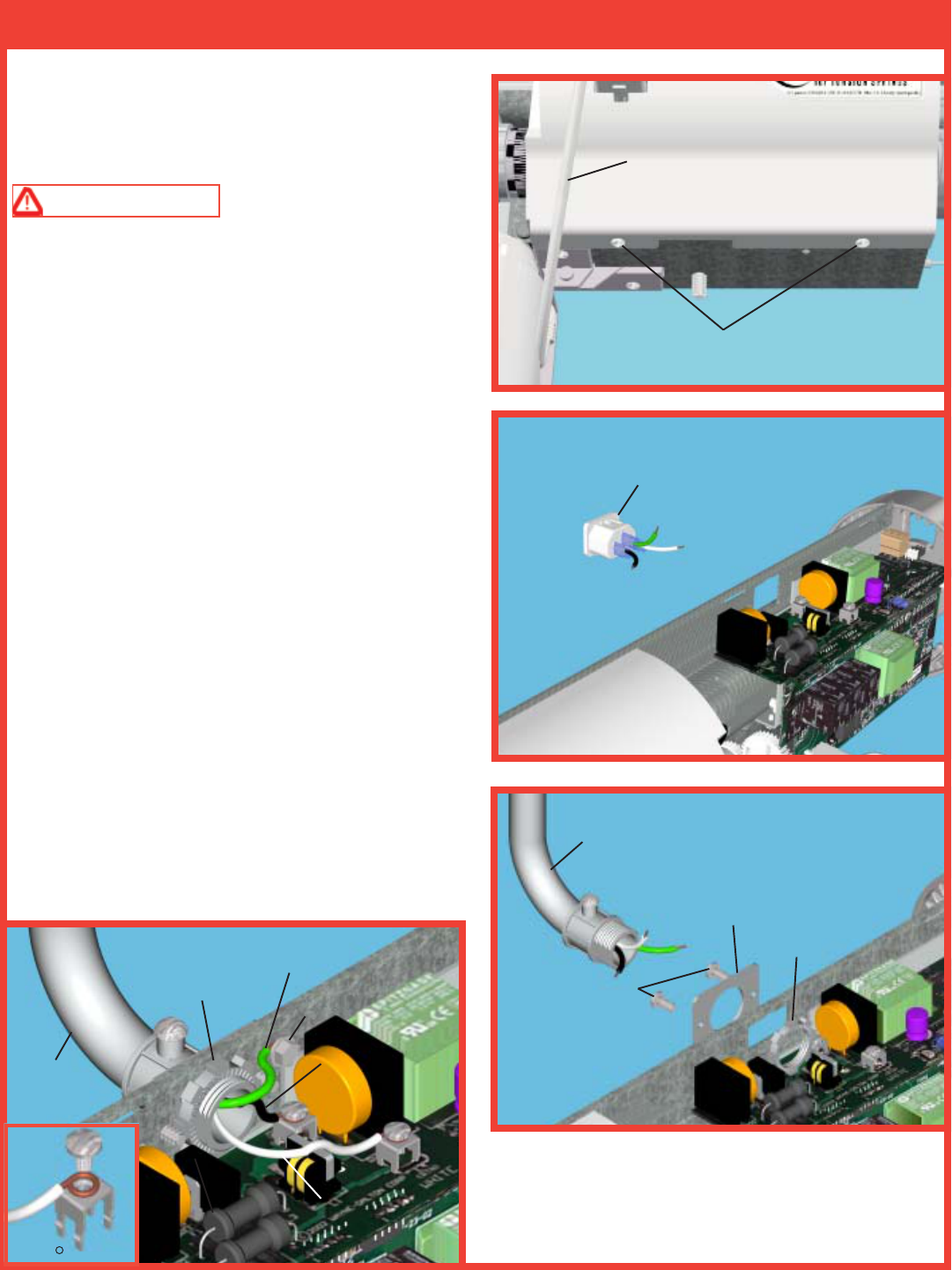
Step 12: Power Connection (Permanent Wiring Option)
Where required by local codes, the opener must be
permanently wired. Services of a licensed electrician can
be obtained to perform the following permanent wiring
procedure.
WARNING TO AVOID ELECTRICAL
SHOCK, DISCONNECT POWER AT FUSE/
BREAKER BOX BEFORE PROCEEDING.
Using a phillips head screwdriver, remove the two
screws from the right hand cover and unplug motor
power cable. Remove right hand cover from the opener
to expose electronics and wiring.
Remove the inlet connector, including its wires and
discard. Install the hardwire plate provided, using (2)
#6-25 x 1/4" screws provided.
Attach conduit, insert field wires and cut wires to allow
an additional 6" of length. Strip off 3/4" of insulation
from each wire. Install wires to the screw terminals on
the circuit board with a 360 degree loop, as shown in
lower left illustration. Black wire to BLK terminal, white
wire to WHITE terminal and the green with yellow stripe
wire to the frame with the provided #8 screw.
Position wiring as shown in the lower left illustration,
keeping them to the left side of the circuit board.
Replace the right hand cover over the opener’s
electronics and secure with the two screws. Plug motor
power cable into opener.
HARD WIRE
PLATE
(2) SCREWS
#6-25 X 1/4”
CONDUIT
NUT
CONDUIT
INLET
CONNECTOR
CONDUIT
CONDUIT
NUT
GREEN/YELLOW
(GROUND)
WHITE
(NEUTRAL)
BLACK
(LIVE)
(2) SCREWS
MOTOR
POWER
CABLE
360 LOOP
#8 SCREW
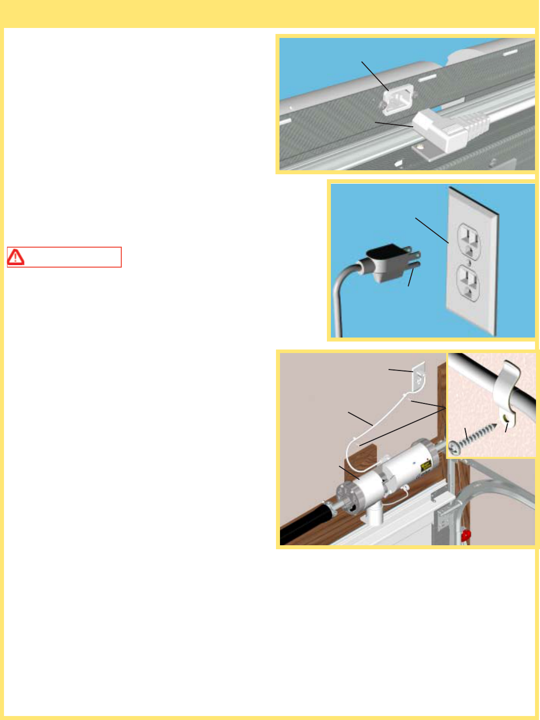
Plug the female end of power cord into the inlet
connector on the back side of opener. Plug the other
end of the opener power cord into the nearest convenient
power receptacle. (If the power cord is not long enough
to reach the closest receptacle, contact a service person
for further options.) As soon as power is applied to the
opener the opener will beep.
Excess power cord length must be routed and contained
safely away from any moving members.
NOTE: Do not permanently attach power cord to
building! Use only the flexible plastic clips supplied
with the opener.
WARNING TO REDUCE THE RISK OF
ELECTRICAL SHOCK, THIS EQUIPMENT HAS A
GROUNDING TYPE PLUG, THAT HAS A THIRD
(GROUNDING) PIN. THIS PLUG WILL ONLY FIT
INTO A GROUNDING TYPE OUTLET. IF THE PLUG
DOES NOT FIT INTO THE OUTLET, CONTACT A
QUALIFIED ELECTRICIAN TO INSTALL THE
PROPER OUTLET. DO NOT CHANGE THE PLUG
IN ANY WAY.
17
Step 13: Power Connection (Standard Wiring)
INLET CONNECTOR
FEMALE
END
POWER
RECEPTACLE
6’ POWER
CORD
OPENER
POWER
RECEPTACLE
GROUNDING
PIN
PLASTIC
CLIP
#6 X 7/8”
PAN HEAD
SCREW
18
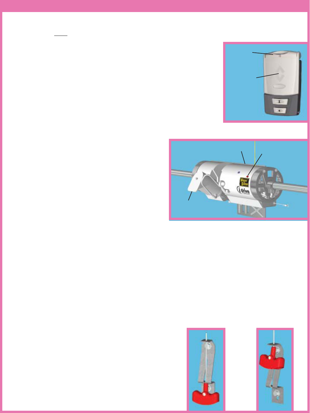
Step 14: Wall Station Activation and Programming
NOTE: The following steps describe the process to activate the Wireless Wall Station security code and
programming Wireless Wall Station to the opener.
NOTE: The user must activate the wall station before using the wall station.
Wall Station Activation:
NOTE: Activation of the wall station is only necessary at installation and
before first use of the wall station.
To activate wall station:
1. Press and hold the wall station’s Light button. The Up/Down button red
LEDs will blink rapidly.
2. After 2 seconds, the LEDs will turn on continuously indicating a successful
activation. Release Light button. The wall station is now ready to be
programmed to the opener.
Wall Station Programming:
To program wall station:
1. Verify the emergency disconnect handle is in the manual
door operated position (lower position). This is for safety
reasons.
2. On the front cover of the opener, press and release the
red program button; the opener will beep once, indicating
activation of the program mode. The opener will remain
in program mode for 30 seconds.
3. Press and hold the wall station light button until the
opener beeps one time. The wall station is now
programmed.
4. Return the emergency disconnect handle to the motor operated position (upper position).
No beeping response of the opener during the wall station programming indicates a programming failure.
Repeat programming Steps 1-4.
NOTE: Programming failure can occur during the wall station programming if the remote control is too close
to the opener during the programming sequence. Perform the programming with a minimum of six feet between
the remote control and the opener.
NOTE: The first wall station command, after programming, will only move the door through a six-inch up
cycle. Normal door operation will occur on the second usage of the wall station. The six inch door move cycle
will not happen if the install routine has not been run.
NOTE: The opener can be activated by up to six remote control
devices (including wall station, transmitter, and keyless entry
devices). If a seventh control is programmed, the first of the
programmed controls will be overridden and will no longer
activate the opener.
CAUTION: For safety reasons, manually disconnect the
opener from the door using the emergency disconnect handle
prior to erasing remote controls. To clear programming of all
remote control devices, press and hold the opener’s program
button for approximately ten seconds. When the opener beeps
three times, all remote controls are erased.
LIGHT
BUTTON
UP/DOWN
BUTTON
HANDLE IN MOTOR
OPERATED POSTION
HANDLE IN MANUAL
OPERATED POSITION
OPENER
MOTOR IN UP
POSITION
RED PROGRAM
BUTTON

RED PROGRAM
BUTTON
1. Press the red program button on the light fixture. The LED on the light fixture
will turn on and remain on for 30 seconds or until a Wall Station is learned. The
incandescent lamp will also turn on when program button is pushed.
2. Press the Light Button on the Wall Station. This must be done within 30 seconds
of pressing the program button on the light fixture. The light fixture lamp and
LED will blink three times to indicate successful programming. The light fixture
can now be turned on and off from this Wall Station and automatically turned on
by the opener programmed to this Wall Station.
NOTE: A single opener can be programmed to activate multiple light fixtures if
desired by repeating the above steps with additional light fixtures programmed to
the desired opener.
NOTE: A single Light Fixture can be programmed to be activated by up to six
openers. In other words a maximum of six openers can be learned by one light
fixture.
To clear all Openers from a light fixture’s memory press and hold the red program
button on the light fixture for approximately 10 seconds until the LED and
lamp starts blinking (six blinks).
At this point the light fixture is ready to set new programming.
Step 15: Program Light Fixture
LIGHT
BUTTON
19
20
During install routine, the door will move up and down twice. Always keep a moving door in sight and keep
people and objects away until it is completely closed. Pull the emergency disconnect handle to the manual door
operated position (lower position). Manually raise the door to the full upward position. Then manually lower
the door to the fully closed position. Make sure there are no obstructions in the path of the door. Return the
emergency disconnect handle to the motor operated position (upper position).
WARNING THE OPENER SHOULD ONLY BE DISCONNECTED WHILE THE DOOR IS IN
THE CLOSED (DOWN) POSITION. OTHERWISE, IN CASE OF WEAK OR BROKEN SPRING(S), THE
DOOR COULD FALL, CAUSING SEVERE OR FATAL INJURY.
HELPFUL HINTS: Manually move the door slowly upwards
after pulling the manual emergency disconnect handle. If there
is interference between the top of the door and the opener’s
housing try repositioning the top roller bracket as far up as
possible. The top roller brackets are located on the garage door
top panel (closest to the ceiling). Loosen the nuts from the slider
bracket (if present). Then, remove the screws holding the bracket
to the door panel. Raise the top roller bracket and re-attach. Re-
align the top roller in the track by moving the slider bracket
until the door section meets the weather seal. Re-tighten nuts.
Repeat for the other side.
CAUTION: To avoid the top panel from falling, complete re-installation on one side before beginning
the other.
NOTE: If no obstructions interfere with the door when manually opened and closed, proceed to Step 16 a.
However, if an object such as a ceiling beam obstructed the door from opening completely, set a custom upper
limit setting during the install routine, Step 16 b.
NOTE: The door must be in its fully closed position and the disconnect handle must be in the motor operated
position (upper position) to initiate the install routine.
NOTE: Install routine will not run if infrared safety sensors are not aligned. (see Step 20 for IR sensor alignment.)
WARNING TO AVOID INJURY, NO ONE SHOULD CROSS THE PATH OF A MOVING
DOOR!
HELPFUL HINTS:
Step 16 a: Install routine with standard upper limit
Press and release the profile button. The opener will beep twice, indicating the
activation of the install routine. The door will now move to the full open position
and stop. Then, the door will close completely. Next, the door will go through
one more up/down cycle. Once this is complete, the door limits are set and the
installation is complete.
Step 16 b: Install routine with custom upper limit
Press and release the profile button. The opener will beep twice, indicating the
activation of the install routine. When the door moves to the desired height, at
least four feet off the ground, press the up/down button on the wall station. The
door will stop and then close completely. Next, the door will go through one
more up/down cycle. Once this is complete, the door limits are set and the
installation is complete. Alternately: After an install routine has been completed,
the door can be disconnected and manually moved to the desired upper limit. Reconnect door and initiate a new
install routine from the new upper position.
Step 16: Install Routine
SLIDER
BRACKET
TOP
BRACKET
SCREWS
TOP
ROLLER
HORIZONTAL
TRACK
BOLTS AND NUTS
UP/DOWN
BUTTON
PROFILE
BUTTON
IMPORTANT! - FOR SYSTEM SECURITY: The motor is designed to pivot down after the door closes
completely. If the motor does not pivot or pivots too soon, the detent may need to be adjusted in order for the
door lock feature to work properly. Proceed to next step: Detent adjustment.
IMPORTANT! Before making any detent pin
adjustments, check the door balance. Door should not
raise off the floor with spring tension alone, nor should
it free fall from any open position.
The amount of pressure the opener uses to pivot the
motor downward is preset at the factory via the detent
pin adjustment screw. Due to variations in door
installations, a detent pin adjustment may need to be
made with a flat head screwdriver in order for proper
pivoting of the motor.
A.) If the motor does not pivot down,
or only pivots down partially, the detent
pin is set too hard. Using a flat head screwdriver, turn the detent pin COUNTER CLOCKWISE
in 1/4 turn increments. Then operate the door to confirm adjustment. If the motor does not pivot
on door closing adjust detent pin again. Repeat procedure until motor pivots to full down position when the
door is completely closed.
B.) If the motor pivots down prematurely (before the door is completely closed) or if the motor
is “slapping” too aggressively against the top of the door, the detent pin is set too soft. Using a
flat head screwdriver, turn the detent pin CLOCKWISE in 1/4 turn increments. Then operate
the door to confirm adjustment. If the motor pivots to soon, adjust detent pin again. Repeat
procedure until motor pivots to full down position when the door is completely closed.
21
Step 17: Detent Adjustment (if required)
Step 18: Setting the Lock
The opener has built into it a means of locking the door
when in the fully closed position. The motor cover is
designed to act as an obstruction to the door while in
the down position. The lock is adjustable to allow for
proper interface with your door.
The lock ring and lock are assembled to the highest
position. Once the door and opener have been installed
and the opener has been programmed, the lock adjustor
needs to be adjusted. Unscrew the lock adjustor until it
is 1" from the top of the door. Once the lock is set at
desired position, screw the lock ring down to the lock
to prevent it from moving.
Disconnect opener and manually operate the door to
confirm door clears the lock. Reconnect opener and
cycle the door to make sure that the lock adjustor does
not hit the door during the cycle sequence. Adjust the
lock accordingly.
TOP DOOR SECTION
LOCK ADJUSTOR/
MOTOR
DETENT PIN
LOCK RING
LOCK
ADJUSTOR
22
Step 20: Photoeletric Safety Sensor Alignment
IMPORTANT! - This infrared safety sensor sends an invisible beam of light from the sending unit to the
receiving unit across the pathway of the door. The door opener will not operate until the safety sensor is
connected to the power unit and properly aligned. If the invisible beam of light is obstructed, an open door
cannot be closed by the transmitter or a momentary activation of the wall mounted push button. However, the
door may be closed by holding your finger on the wall push button (constant pressure) until the door travels to
a fully closed position. At this point you will be able to activate the opener; it will open, but will not close the
door unless the sensors are aligned. The safety sensors can be aligned by moving the sending and receiving
units in or out (see Fig. 1)until the alignment light on the receiving unit comes on. The 1/4-20 carriage bolt can
be loosened to move the unit in or out, as required. If you have difficulty aligning beams, check that both
brackets are mounted at the same height and remount if necessary. Additional minor adjustments can be made
by lightly bending the mounting brackets (see
Fig. 2).
WARNING FAILURE TO
MAKE ADJUSTMENTS COULD RESULT
IN SEVERE OR FATAL INJURY.
Once the alignment light comes on, tighten all
bolts and mounting screws. Finish securing all
wire making sure not to break or open any of
the conductors. Loop and secure any extra
wire. Now, using the wall station’s up/down
button, activate the opener and check that it
will operate through full open and close cycles.
Custom pet position: Normal install routine sets the pet position to
approximately eight inches above the ground. The pet opening height
may be changed to open anywhere between 8” and 30” above the ground.
To change the automatic pet opening height refer to the following
procedure:
1. After completion of the normal install routine, with the door in the
closed position, place the disconnect handle in the manual operated
position.
Manually position the door to the desired pet opening height (between
8” and 30” above ground) and return disconnect handle to the motor
operated position.
2. Move the slide switch from the NORMAL (Unlock) position to the
DOOR LOCK (Lock) position and then back to the NORMAL (Unlock)
position. The opener will beep once. The pet button is now programmed to automatically open the door to this
custom height.
NOTE: The opener will NOT accept programmed pet lock position if door is below 8” or higher than 30”.
NOTE: Activation of the normal install routine will reset the pet position to the default eight inch target height.
For use of the pet button see Operation section.
1/4-20 CARRIAGE BOLTS
Top View
Align in Center
(In/Out)
Top View
Align in Center
For this adjustment bend bracket at
wall mount
FIG. 1
FIG. 2
IN
OUT
IN
OUT
Step 19: Custom Settings
PET
BUTTON
NORMAL
(UNLOCK)
DOOR LOCK
(LOCK)
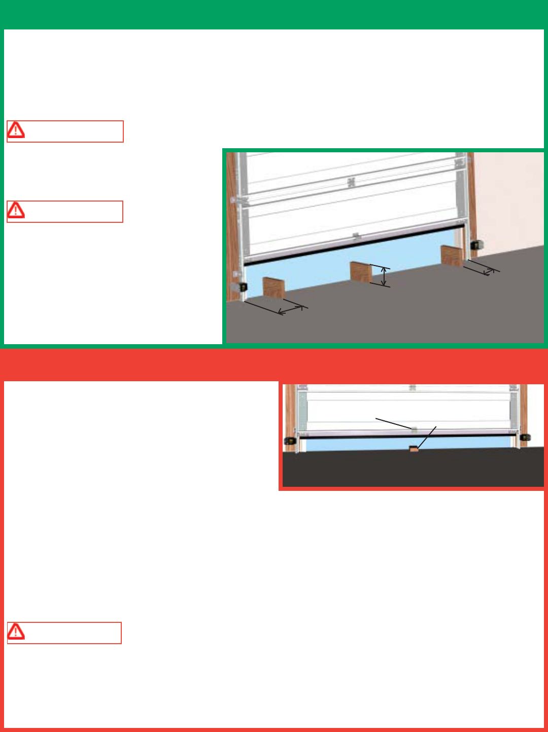
After installing the opener, the door must reverse when
it: contacts a 1-1/2" high object (or a 2 x 4 board laid
flat) on the floor. To verify proper operation:
1. Using the wallstation, activate the door to the fully
open position .
2. Place a 2 x 4 board laid flat on the garage floor under
the door path.
3. Activate the door to the closed position with the wallstation. Upon contacting the 2 x 4 board, the door
should stop, then reverse direction within two seconds and travel to the full open position. If the door does not
respond to the required tests, repeat install routine making sure the door is in the fully closed position prior to
activation.
If problem persists contact Wayne Dalton Customer Service (888) 827-3667
WARNING IF OPENER DOES NOT RESPOND PROPERLY AND FAILS EITHER OF THE
TWO TESTS (STEP 21 AND 22), DOOR MAY CAUSE A SEVERE OR FATAL INJURY. HAVE A QUALIFIED
SERVICE PERSON MAKE NECESSARY REPAIRS.
Starting with the door in the fully open position, place a 6" high object on the floor progressively one foot from
the left side of the door, center of door and one foot from the right side of the door. In each position, activation
of the opener with the wallstation up/down button should cause the door to move no more than one foot, stop
and then reverse to fully open position.
The same 6" high object when placed on the floor, while door is closing, should also cause the door to reverse.
WARNING WHEN PERFORMING THIS PART OF THE TEST, DO NOT PLACE YOURSELF
UNDER DESCENDING DOOR, OR
SEVERE OR FATAL INJURY MAY
RESULT.
WARNING IF THE OPENER
DOES NOT RESPOND PROPERLY, OR
FAILS THESE TEST, HAVE A
QUALIFIED SERVICE PERSON MAKE
NECESSARY ADJUSTMENTS/REPAIRS.
FAILURE TO MAKE ADJUSTMENTS
COULD RESULT IN SEVERE OR FATAL
INJURY.
23
Step 21: Photoelectric Obstruction Sensor Test
12”
6” 12”
Step 22: Contact Obstruction Test
CENTER OF
DOOR
2 X 4 LAID FLAT
ON FLOOR
24
NOTE: If there are any accessories included with your opener, install them per their instructions at this time.
TRANSMITTER ACTIVATION:
NOTE: Activation of the transmitter is only necessary at installation and before first use of the transmitter.
To activate transmitter:
1. Press and hold the transmitter’s Large button. The
red LEDs will blink rapidly.
2. After 2 seconds, the red LEDs will turn on
continuously indicating a successful activation.
Release Large button. The transmitter is now ready
to be programmed to the opener.
TRANSMITTER PROGRAMMING:
To program transmitter:
1. Place the emergency disconnect handle in the
manual door operated position. This is for safety
reasons.
2. On the front cover of the opener, press and release
the red program button; the opener will beep once,
indicating activation of the program mode. The opener
will remain in program mode for 30 seconds.
3. Press and hold the desired transmitter button until;
the opener beeps once. The transmitter is now
programmed.
4. Return the emergency disconnect handle to motor
operated position.
NOTE: No beeping response of the opener during the transmitter programming indicates a programming
failure. Repeat programming 1-4.
NOTE: Programming failure can occur during the transmitter programming if the remote control is too close
to the opener during the programming sequence. Perform the programming with a minimum distance of six
feet between the remote control and the opener.
NOTE: The first transmitter command, after programming, will only move the door through a six-inch up
cycle. Normal door operation will occur on the second usage of the transmitter.
NOTE: The opener can be activated by up to six remote control devices (including wall station, transmitter,
and keyless entry devices). If a seventh control is programmed, the first of the programmed controls will be
overridden and will no longer activate the opener.
CAUTION: For safety reasons, manually disconnect the door from opener using the emergency
disconnect handle prior to erasing remote controls. To clear programming of all remote control devices,
press and hold the opener’s program button for approximately ten seconds. When the opener beeps three
times, all remote controls are erased.
HANDLE IN MANUAL DOOR
OPERATED POSITION
LARGE
BUTTON
PROGRAM BUTTON
Step 23: Transmitter Activation and Programming
MOTOR IN UP POSITION
LED

NOTE: This step can only be done on automobiles equipped with the HomeLink™ System.
CAUTION:
During programming, the garage door may operate. Pull the emergency disconnect handle to put the operator
in the manually operated position. Make sure people and objects are out of the way of the moving door to
prevent potential harm or damage.
NOTICE: Programming Homelink™ requires a Wayne-Dalton transmitter that is programmed to the Torsion
iDrive™ per Step 23.
ATTENTION:
Use the programming instructions provided with your vehicle first. Follow these instructions if the HomeLink™
unit does not learn the transmitter.
PROGRAMMING
Training HomeLink™ Unit
1. Pull the emergency disconnect handle to the manually operated position.
2. Press and hold the two outside buttons on the HomeLink™ unit for approximately 20 seconds until the
HomeLink™ light begins to flash (approx. 1 flash per second), then release both buttons. (Do not perform this
step to train additional hand-held transmitters.) Note that this operation erases all previously learned transmitters
and that you need to re-teach any other transmitters to your HomeLink™ unit by repeating steps 3 - 6 below.
3. Hold the end of the Wayne-Dalton® hand-held transmitter approximately 1 to 3 inches away from the
HomeLink™ surface – keeping the HomeLink™ indicator light in view.
4. Press and hold the Wayne-Dalton hand-held transmitter’s large center button. The transmitter’s red LED
indicator will turn on. After 10 seconds the red indicator (LED) will begin to blink rapidly. Continue to hold the
button pressed.
5. While still holding the Wayne-Dalton transmitter button (red indicator blinking rapidly), immediately press
the desired HomeLink™ button. Keep pressing the buttons until step 6 has been completed.
6. The HomeLink™ indicator light will be blinking during the training operation. When the HomeLink™
indicator light flashes rapidly or turns off (approx. 5 to 60 seconds), both buttons may be released. The
HomeLink™ light flashing rapidly or turning off indicates successful programming of the new frequency
signal.
Teaching Power Unit
7. Now press the PROGRAM SWITCH button located on the idrive™ opener. The idrive™ unit will beep,
indicating that it is ready to learn.
8. Now press the HomeLink™ button used in Step 5 above for 1 to 3 seconds. idrive™ will beep once
indicating a successful learn.
9. Return the emergency disconnect handle to the motor operated position.
10. Press the HomeLink™ button once more to operate the door. The first door operation after programming
will only move the door through a six inch up. Normal door operation will follow.
Step 24: Programming HomeLink™ to the Torsion iDrive™
25
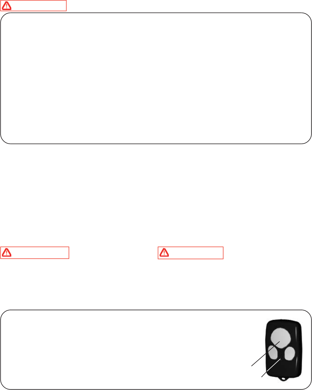
Momentarily pressing the large transmitter button or the button programmed in the transmitter
programming step activates the door. Other buttons can also be programmed to activate
different doors, for multi-door installations. Each button or a combination of two buttons
pressed simultaneously can be programmed to activate a different door. Only one button at a
time can be programmed to activate a specific opener. The transmitter LED will light while
any transmitter button remains pressed.
NOTE: Refer to Step 23 for transmitter programming instructions.
Operation:
WARNING
TO REDUCE THE RISK OF SEVERE OR FATAL INJURY:
WARNING NEVER LET CHILDREN
OPERATE OR PLAY WITH THE DOOR CONTROLS.
KEEP REMOTE CONTROLS AWAY FROM
CHILDREN. FATAL INJURY COULD RESULT
SHOULD A CHILD BECOME TRAPPED BETWEEN
THE DOOR AND THE FLOOR.
WARNING ALWAYS KEEP A MOVING
DOOR IN SIGHT AND KEEP PEOPLE AND
OBJECTS AWAY UNTIL IT IS COMPLETELY
CLOSED. TO PREVENT A SEVERE OR FATAL
INJURY, AVOID STANDING IN A OPEN DOOR WAY
OR WALKING THROUGH THE DOORWAY WHILE
THE DOOR IS MOVING.
26
Important Safety Instructions
1. READ AND FOLLOW ALL INSTRUCTIONS.
2. Never let children operate or play with the door controls. Keep remote controls away from children.
3. Always keep a moving door in sight and keep people and objects away until it is completely closed. NO
ONE SHOULD CROSS THE PATH OF A MOVING DOOR.
4. NEVER GO UNDER A STOPPED, PARTIALLY OPEN DOOR.
5. Test the door opener monthly. The garage door MUST reverse on contact with a 1-1/2 inch high object (or a
2 x 4 board laid flat) on the floor. After adjusting the limit of travel or profiling (install routine) retest the door.
Failure to adjust the opener properly may cause severe or fatal injury.
6. When possible, use the emergency disconnect only when the door is in the closed position. Use caution
when using the emergency disconnect when the door is open. Weak or broken spring(s) may allow the door to
fall rapidly, causing a severe or fatal injury.
7. KEEP THE GARAGE DOOR PROPERLY BALANCED. See the owner’s manual included with the
door. An improperly balanced door could cause a severe or fatal injury. Have a qualified service person make
repairs to the cables, spring assemblies, and other hardware.
8. SAVE THESE INSTRUCTIONS.
Door activation: Upon activation by either the wall station up/down button or transmitter, the door will move in
the following manner:
1. If closed, the door will open. If open completely, the door will close. If partially open, the door will open.
2. If closing, the door will stop, reverse, and return to the open position. Next activation will close the door.
3. If opening, the door will stop. Next activation will open the door.
4. If an obstruction is encountered or an out-of-balance condition is detected while the door is closing, the door
will reverse, return to the open position, and the opener will beep (3) or (4) times. The next activation will close
the door.
5. If an obstruction is encountered or an out-of-balance condition is detected while opening the door, the door will
stop. The next activation will open the door.
6. When door is in motion any button on the wall station functions the same as the up/down button.
Transmitter Operation:
LARGE
BUTTON
LED
27
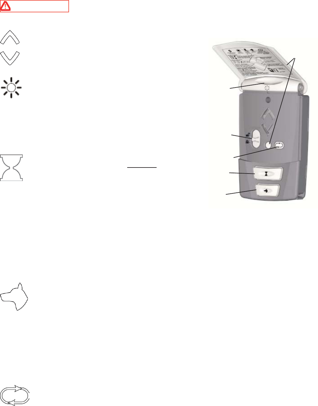
HOW TO OPERATE THE WIRELESS WALL STATION
WARNING TO PREVENT POSSIBLE INJURY, NEVER LET CHILDREN OPERATE OR PLAY
WITH DOOR CONTROLS. KEEP REMOTE CONTROL AWAY FROM CHILDREN.
Momentarily pressing the Up/Down button starts or stops
door movement or changes door’s direction. Press and
hold Up/Down button during the door’s complete
downward travel to override photo eye safety sensors.
Momentarily pressing the Light button turns on the light
fixture. The light will remain on until either the Light
button is pressed again or the door is activated. The light
automatically turns on with a door activation and remains
on for five minutes thereafter. Pressing the Light button before the
five minutes has elapsed will turn off the light fixture. While the
door is in motion, the Light button functions identical to the Up/
Down button, stopping or reversing the door immediately.
Momentarily pressing the Timer button causes a
delayed activation of a stationary fully open door. The
opener will beep on and off for about 10 seconds prior to
closing the door, allowing enough time to exit the
garage when the opener is in the timer mode. Pressing
any button, except for the Profile button while the opener is
beeping or the lamp is blinking cancels the timer mode.
NOTE: The timer feature will only function with the door in the full open position. Pressing the Timer
button with a stationary door in any other position will cause the opener to beep four times and the door
will not be activated.
While the door is in motion, the Timer button functions identical to the Up/Down button, stopping or reversing
the door immediately.
Pressing the Pet button opens a closed door to a preset position between eight and thirty inches
above the floor, allowing pets to enter and exit the garage without the door being fully open. The
door must be fully closed to activate the pet open feature. Pressing the Pet button with a stationary
door in the pet open position will cause the door to close. Pressing the Up/Down button while the
door is in the pet position will cause the door to open. While the door is in motion, the Pet button
functions identically to the Up/Down button, stopping or reversing the door immediately. The pet feature allows
for custom setting of the pet position door height. Refer to the opener’s manual for complete Pet button
instructions and programming. See Step 19: Custom Settings.
NOTICE: A door in the “pet position” (open 8-30 inches) is not locked and should not be considered to be
in a secured door position.
Press and release the Profile button to intiate the “Install Routine”. Refer back to Step 16 for
complete Install Routine instructions and functions.
NOTE: The wall station’s arrow LEDs will light while any wall station button remains pressed.
LIGHT
BUTTON
UP/DOWN
BUTTON
SLIDE
SWITCH
TIMER
BUTTON
PET
BUTTON
PROFILE
BUTTON
HOW TO OPERATE THE WIRELESS WALL STATION (CONTINUED)
The slide switch has two positions: Normal, and Door lock (Disable RF).
Normal position:
Move the slide switch to Normal position for all normal functions of the opener. The Normal
position will cancel the Door Lock feature.
NOTE: Keep the slide switch in the Normal position unless you have fully read and
understood the Door Lock setting and you desire to use this setting.
Door Lock position:
If the door is stopped (fully open, fully closed or partially open) move the slide switch to the Door Lock
position to suspend all normal functions of the opener. The opener will remain completely disabled and non-
operational in this mode. All wall stations, transmitters and keyless entry units are ignored until the slide switch
is moved to the Normal position.
If the door is moving when the slide switch is moved to the Door Lock position, the Door Lock mode is not
activated and all functions of the opener remain active.
Backlit LED Lights:
The Up/Down button backlit red LEDs blink intermittently often to help you locate the wall station in a dark
garage. This blink rate can be changed for longer battery life or can be turned off. The default blink rate is one
blink every one second.
NOTE: The wall station’s Up/Down arrow LEDs will light while any wall station button remains pressed.
For longer battery life the blink rate can be changed to blink once every two seconds. To change the blink rate,
remove the battery cover and remove one battery. Re-install the battery and within 2 seconds, press the Light
button. Re-install the battery cover.
For longest battery life, the blink can be turned off. To turn off the blink, remove the battery cover and remove
one battery. Re-install the battery and within 2 seconds, press the Pet button. Re-install the battery cover.
28
NORMAL
DOOR LOCK
DISCONNECTED, MOTOR UP POSITION
MOTOR DOWN POSITION (DOOR LOCKED)
29
WARNING KEEP THE GARAGE DOOR PROPERLY BALANCED. AN IMPROPERLY
BALANCED DOOR COULD CAUSE A SEVERE INJURY. HAVE A QUALIFIED SERVICE PERSON MAKE
REPAIRS TO CABLES, SPRING ASSEMBLIES, AND OTHER HARDWARE.
WARNING THE EMERGENCY DISCONNECT SHOULD ONLY BE USED WHEN THE DOOR
IS CLOSED. USE EXTREME CAUTION IF OPERATING THE EMERGENCY DISCONNECT ON AN OPEN
DOOR. WEAK OR BROKEN SPRING(S) MAY ALLOW THE DOOR TO FALL RAPIDLY, CAUSING A
SEVERE OR FATAL INJURY.
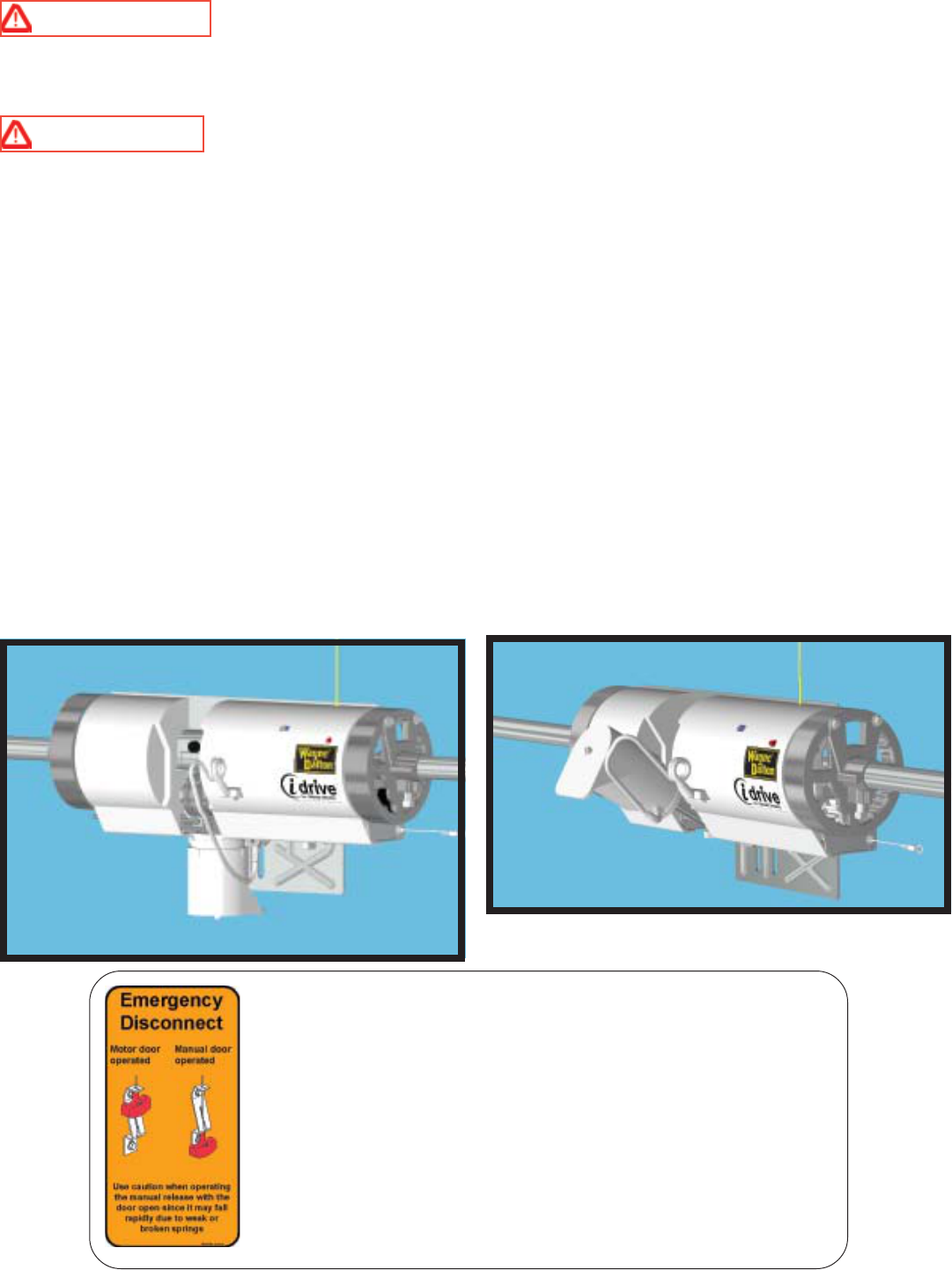
The opener is equipped with an emergency disconnect that allows the door to be moved manually and independent
from the opener.
With the door closed, pull down on the disconnect handle and place the handle under the lower section of the
handle bracket. This motion causes the motor on the opener to pivot upwards and the opener to disconnect from
the torsion tube.
Releasing the disconnect handle from the lower section on the handle bracket and returning the handle to its
original position will reconnect the opener to the torsion tube.
NOTE: The motor will not pivot down completely when the handle is released. After one motorized up/
down door cycle, the motor will once again pivot down, and all cable slack will be taken up. The garage
door is not locked, secure from forced entry, until the motor is back in the down position.
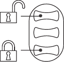
Disconnect Label: The label is located next to the disconnect handle.
The adjacent view shows the handle in both the motor operated and
manual operated positions. View on the left side of the label shows the
handle position when the opener is engaged to the torsion tube. The
view on the right side of the label shows the handle when the opener is
disconnected from the torsion tube.
NOTE: Use extreme caution if disconnecting. The emergency
disconnect should not be used when the door is in the open position.
Weak or broken spring(s) may allow the door to fall rapidly causing a
severe or fatal injury.
30
Maintenance:
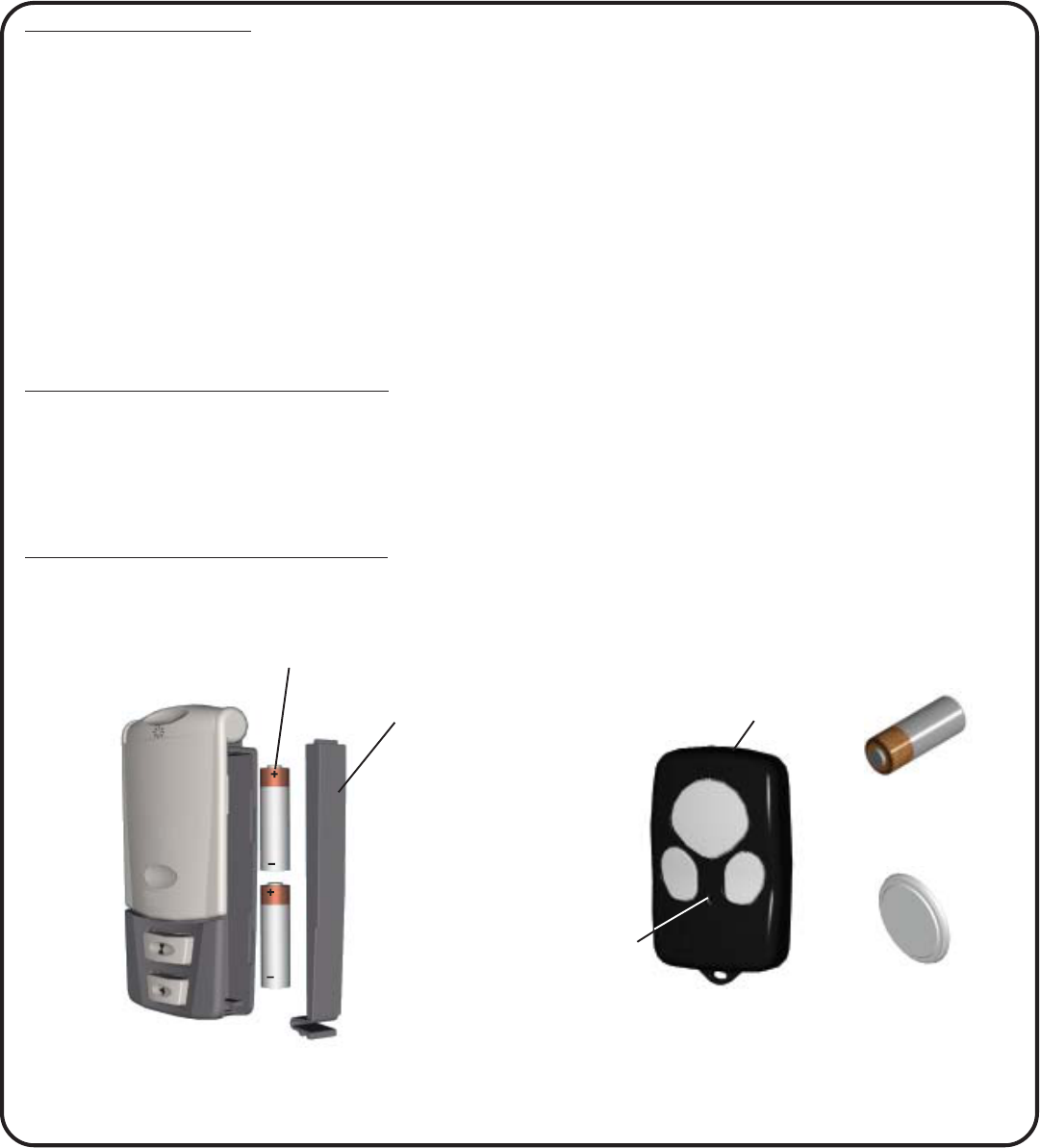
NOTE: Some transmitters use two CR2016 or
equivalent batteries while others use a single MN21
or equivalent battery.
Monthly Maintenance:
1. With door fully closed, manually operate the door with the emergency disconnect in the manual door
operated position. If the door feels unbalanced or binds, have a qualified service person repair or make
adjustments to the door.
2. Perform the contact/obstruction tests. See Step 21 & 22 for the contact/obstruction test instructions. Inability
to activate a door using the transmitter or wall station may be caused by a weak or dead battery. Press and hold
the activation button on either the transmitter or the wall station. If the LED does not light, this is an indication
that the battery is weak or dead. Replace the battery.
NOTE: Dispose of dead batteries properly.
Battery replacement for wall station:
Remove the battery cover completely (right-hand side of wall station) by disengaging the battery cover’s
lower clip. Install two AAA batteries into the wall station observing the polarity, (+) and (-), of both batteries.
After about five seconds, the Up/Down red LEDs will begin to blink every one second. Re-install the battery
cover by first inserting its top into the wall station then inserting and securing its bottom.
Battery replacement for transmitter:
Insert a coin in the coin slot of the transmitter and twist coin to access the dead battery. Replace the battery,
being careful to match the positive (+) symbols on the circuit boards with the battery.
COIN SLOT
LED
MN21
OR
CR2016
NOTE: Use only two AAA batteries.
BATTERY
COVER
TWO AAA
BATTERIES

Troubleshooting
MOTPMYSESUACELBABORPNOITCAEVITCERROC
noitatsllawehtotdnopsertonseodrenepO
?rettimsnartro
.renepoehtotrewopoN
.demmargorptoneraslortnoC
teltuootdrocrewoprenepoehtkcehC
.noitcennoc
gnimmargorpdnanoitavitcaedoceeS
.noitces
tontubnoitatsllawehtmorfskrowrenepO
?rettimsnartehtmorf
.demmargorptonsirettimsnarT
.yrettabrettimsnartdaedrokaeW
gnimmargorpdnanoitavitcaedoceeS
.noitces
yrettabrofnoitcesecnanetniaMeeS
.tnemecalper
tontubrettimsnartehtmorfskrowrenepO
?noitatsllawehtmorf
.demmargorptonsinoitatsllaW
.yrettabnoitatsllawdaedrokaeW
gnimmargorpdnanoitavitcaedoceeS
.noitces
yrettabrofnoitcesecnanetniaMeeS
.tnemecalper
speebrenepoehtdnaevomtonseodrooD
?semitowt .demrofrepneebtonsahenituorllatsniehT.enituorllatsniehtmrofreP
lortnocetomerahtiwevomtonseodrooD
ehtmorfemocspeebondnadnammoc
?renepo
lortnocetomerahtiwevomtonseodrooD
?emitenospeebrenepodnadnammoc
.rekaerbtiucricdeppirtroesufnwolB
.renepoehtotrewopoN
.gniriwrotomdegamadelbissoP
atcatnoCrorekaerbtiucricehtteseR
esufrofnosrepecivresdeifilauq
.noitamrofni
.noitcennocdrocrewopkcehC
.nosrepecivresdeifilauqallaC
renepoehtdna,sesreverrospotsrooD
?semitruofroeerhtspeeb
.deretnuocnenoitcurtsbO
.tnemngilarosnesderarfnI
.detcetednoitidnocecnalab-fo-tuO
.htaproodehtraelC
.srosnesderarfnIngila-eR
.nosrepecivresdeifilauqatcatnoC
?ylreporpesolctonseodrooD ehtnotoneraselbacecnalabretnuoC
.ylreporpsmurd
s'noitatsllawehtoterusserptnatsnocylppA
.roodehtesolcotnottubnwod/pu
?esolctonlliwrooD
thgiedelcycsahroodehT:yaledlamrehT
.doirepetunim-evifanisemit
.tnemngilarosnesderarfnI
.eruliaftsetnoitcurtsbotcatnoC
gnitiawetunim-enoaretfaetarepolliwrooD
.doirep
.srosnesderarfnIngila-eR
atcatnocroenituorllatsniehttaepeR
.nosrepecivresdeifilauq
llufronepollufehtotlevarttonseodrooD
?noitisopesolc
.ecnalabfotuosirooD
.ylreporpmiteserastimilrooD
.nosrepecivresdeifilauqallaC
.enituorllatsniehttaepeR
?roolfehtotgnilaestonsirooD
.hgihoottessitimilroodmottoB
ehttsniagathgitootsilaesroodedistuO
.roodehtfoecaf
roodehtecrofdnarenepoehttcennocsiD
dnarenepoehttcennoceR.roolfehtot
.enituorllatsniehtetavitca
.noitisoplaesrehtaehwtsujdA
?roolfehtraenrotagnisreversirooD
siroodnehwyllufputoviptonseodrotoM
?gninepo
hcumootevahsgnirpsecnalabretnuoC
.)noisrot(noisnet
.nosrepecivresdeifilauqallaC
.nurerebotevahyamenituorllatsnI
?roolfehtraenrotagnisreversirooD
ehttsniagathgitootsilaesroodedistuO
.roodehtfoecaf
ehtotesolcotdecapssikcartlacitreV
otroodehtgnisuac,noitcesroodmottob
.dnib
ostonebotsaoslaesroodehtllatsnieR
.roodehtfoecafehttsniagathgit
litnuroodehtmorfyawakcarttsujdA
.devomersignidnib
ytefasretfaesion"gnippop"sekamrooD
?lasrever
ehtnidengilatoneramurdehtnoselbaC
.evorg
llawehthtiwnwod/puroodehtetarepO
.yllacitamotuangilalliwselbac,noitats
31

The Manufacturer warrants that the idrive™ garage door opener will be free from defects in materials and workmanship including electronic components for a period
of FIVE YEARS from the date of installation, provided it is properly installed, maintained and cared for under specified use and service. The motor has an extended LIFETIME
warranty against defects in materials and workmanship.
This Warranty extends to the original homeowner, providing the garage door opener is installed in his/her place of primary residence. It is not transferable. The
warranty applies to residential property only and is not valid on commercial or rental property.
NO EMPLOYEE, DISTRIBUTOR, OR REPRESENTATIVE IS AUTHORIZED TO CHANGE THE FOREGOING WARRANTIES IN ANY WAY OR GRANT ANY
OTHER WARRANTY ON BEHALF OF MANUFACTURER.
The Manufacturer shall not be responsible for any damage resulting to or caused by its products by reason of installation, improper storage, unauthorized service,
alteration of products, neglect or abuse, any acts of nature beyond Manufacturer’s control (such as, but not limited to, lightning, power surges, water damage, etc.), or attempt to use
the products for other than the customary usage or for their intended purposes. The above warranty does not cover normal wear or any damage beyond Manufacturer’s control or
replacement labor.
THIS WARRANTY COVERS A CONSUMER PRODUCT AS DEFINED BY THE MAGNUSON-MOSS WARRANTY ACT. NO WARRANTIES, EXPRESSED OR
IMPLIED, (INCLUDING, BUT NOT LIMITED TO, THE WARRANTY OF MERCHANTABILITY OR FITNESS FOR A PARTICULAR PURPOSE), SHALL EXTEND BEYOND
THE APPLICABLE TIME PERIOD STATED IN BOLD FACE TYPE ABOVE.
Claims for defects in material and workmanship covered by this warranty shall be made in writing to the dealer from whom the product was purchased within the
warranty period. Manufacturer may either send a service representative or have the product returned to the Manufacturer at Buyer’s expense for inspection. If judged by
Manufacturer to be defective in material or workmanship, the product will be replaced or repaired at the option of the Manufacturer, free from all charges except authorized
transportation and replacement labor.
THE REMEDIES OF BUYER SET FORTH HEREIN ARE EXCLUSIVE AND ARE IN LIEU OF ALL OTHER REMEDIES, THE LIABILITY OF MANUFACTURER,
WHETHER IN CONTACT, TORT, UNDER ANY WARRANTY OR OTHERWISE, SHALL NOT EXTEND BEYOND ITS OBLIGATION TO REPAIR OR REPLACE, AT ITS
OPTION, ANY PRODUCT OR PART FOUND BY MANUFACTURER TO BE DEFECTIVE IN MATERIAL OR WORK SHALL NOT BE RESPONSIBLE FOR ANY DIRECT,
INDIRECT, SPECIAL OR CONSEQUENTIAL DAMAGES OF ANY NATURE.
This Warranty gives you specific legal rights and you may have other rights, which may vary from state to state. However, some states do not allow limitation on how
long an implied warranty lasts or the exclusion or limitation of incidental or consequential damages so the above limitations or exclusions may not apply to you.
LIFETIME LIMITED WARRANTY
Lock Troubleshooting
MOTPMYSESUACELBABORPNOITCAEVITCERROC
roodehtgnirudthgiltonlliwerutxifthgiL
noitatsllawehtgnisserpybronoitarepo
?nottubthgil
.blubthgilytluaF
.elcatpecerotrewopoN
.thgilotdemmargorptonnoitatsllaW
.)xaMW57(blubwenllatsnI
.srekaerbtiucrickcehC
.41petsrepmargorP
ehtgnisunehwpuylluflluptonseodrotoM
?tcennocsidycnegreme
foedisnideppilssahelbactcennocsiD
.eldnah .7petSnisnoitcurtsnirepeldnahllatsni-eR
?evomtonlliwroodehttubstratsrotoM noisrotehtmorfdetcennocsidsirenepO
.ebut
rotom"ehtnisieldnahtcennocsiderusnE
.noitisop"detarepo
.7petSnisnoitcurtsnirepeldnahllatsni-eR
?nwodtoviptonseodrotoM
?sesolcroodehtretfayllaitrapstoviprotoM
.drahoottessiniptneteD
niptnetedehtetator,revirdwercsagnisU
litnustnemercninrut4/1niesiwkcolcretnuoc
roodehtretfanwodstovipyllufrotomeht
.sesolc
ehterofeb(ylerutamerpnwodstoviprotoM
?)yletelpmocsesolcrood .tfosoottessiniptneteD
niptnetedetator,revirdwercsagnisU
rotomlitnu;stnemercninrut4/1niesiwkcolc
dna,sesolcroodretfanwodstovipylluf
.ffostuhsyletaidemmirenepo
Troubleshooting (continued...)
MOTPMYSESUACELBABORPNOITCAEVITCERROC
nehwkcolehthtiwserefretniroodehT
.ecnaraelcgniyfirevyllaunam
.yltcerrocnitessikcoL
.leveltonsiebutnoisrotehT
niptnetedotpudetatorylluftonrotoM
.noitisopdegagne
.81petsreptessikcolerusnE
.nosrepecivresdeifilauqatcatnoC
dnaeldnahtcennocsidehttnuomeR
,launamsihtfo7petSreptekcarb
neewtebnoisnetelbacreporpgnirusne
.eldnahehtdnarenepoeht
32
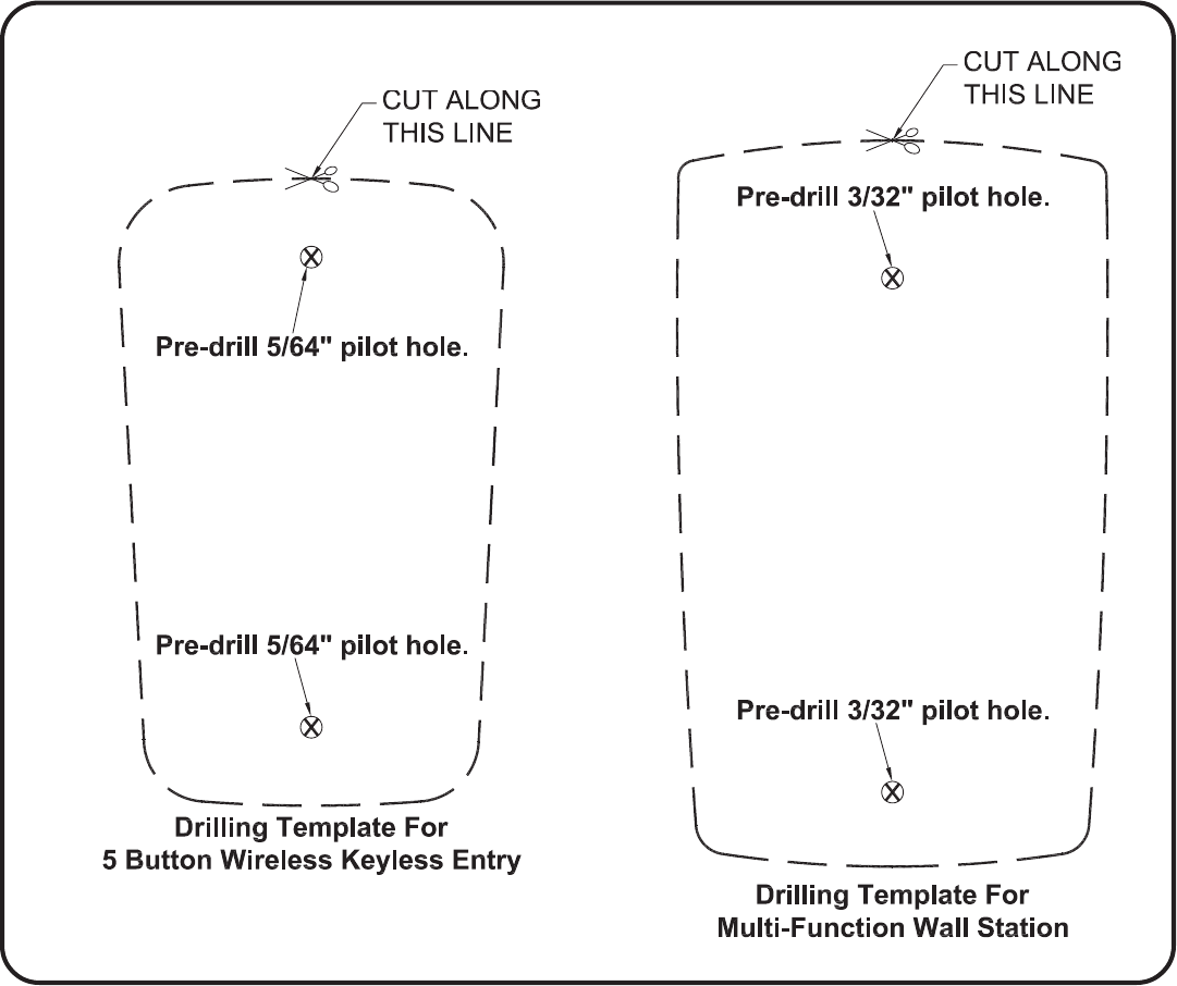
Cut template to aid Installation:
Questions??
For quick answers and helpful advise, call
Wayne-Dalton Customer Service
(888) 827-3667
© Copyright 2003, 2004 Wayne-Dalton Corp.
33