Weatronic 2754-60 FHSS Equipment User Manual
Weatronic GmbH FHSS Equipment
UserManual.wiki
>
Weatronic
>
2754 60 User Manual
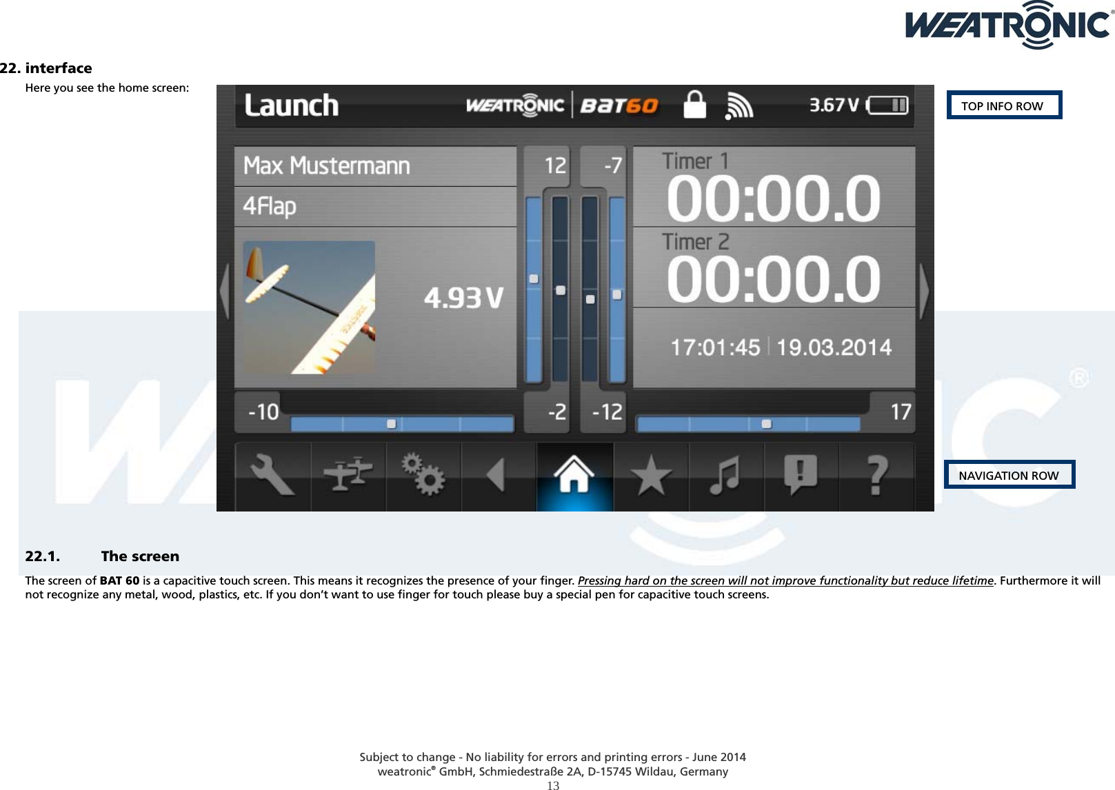
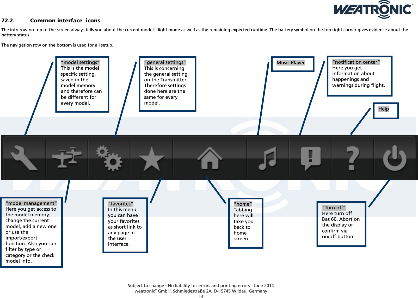
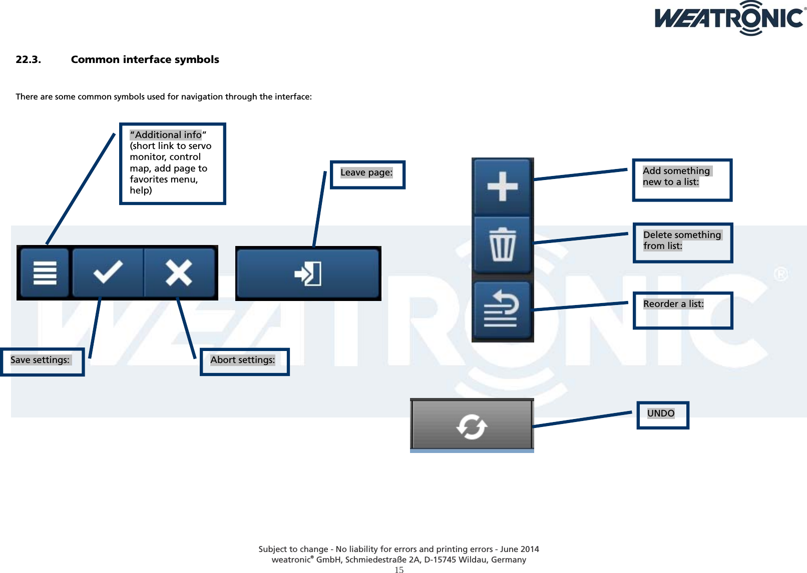
User Manual
Navigation menu
Upload a User Manual
Namespaces
Wiki Guide
HTML
PDF
Info
Views
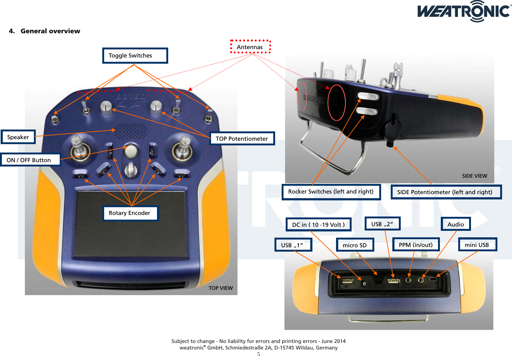
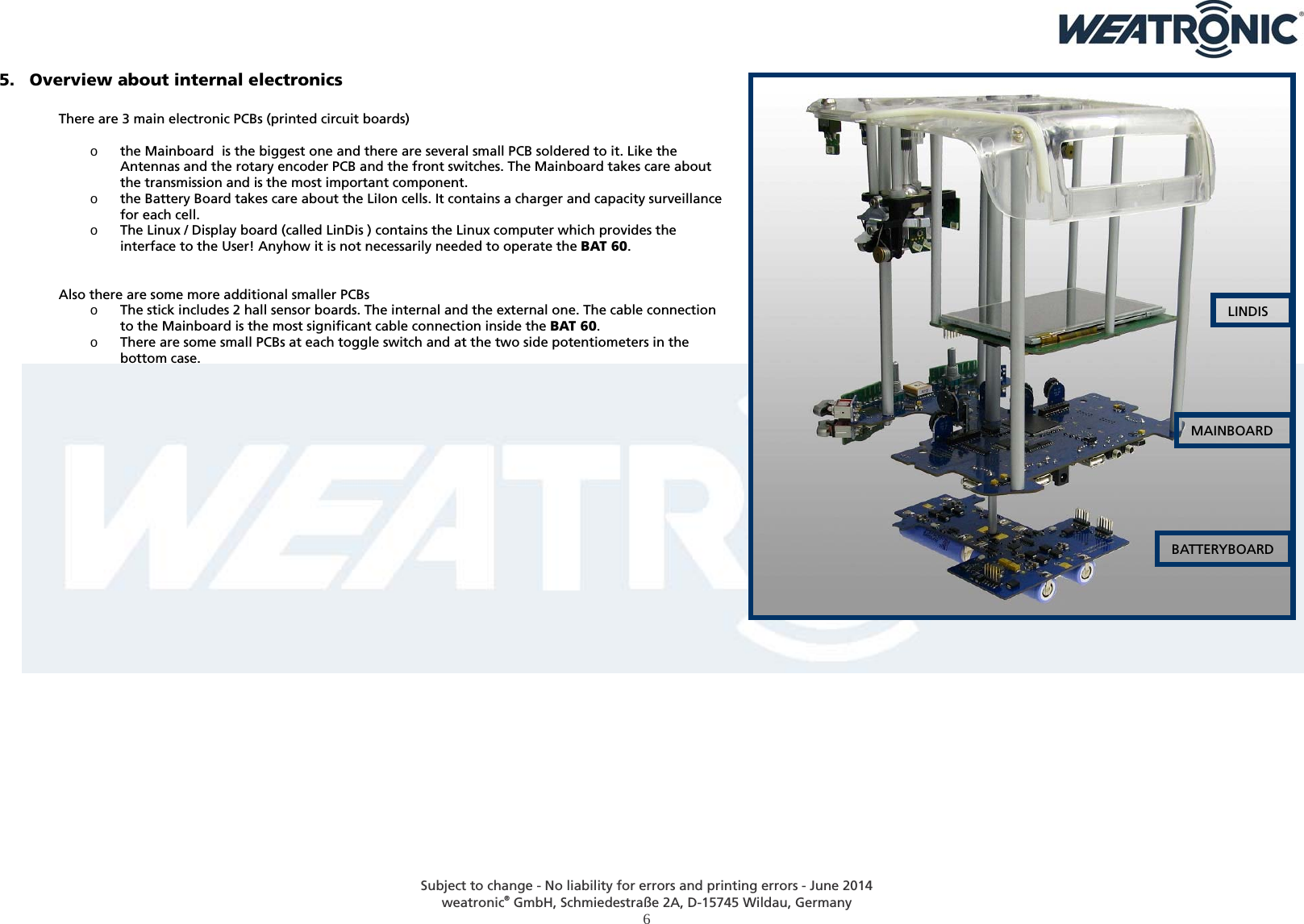
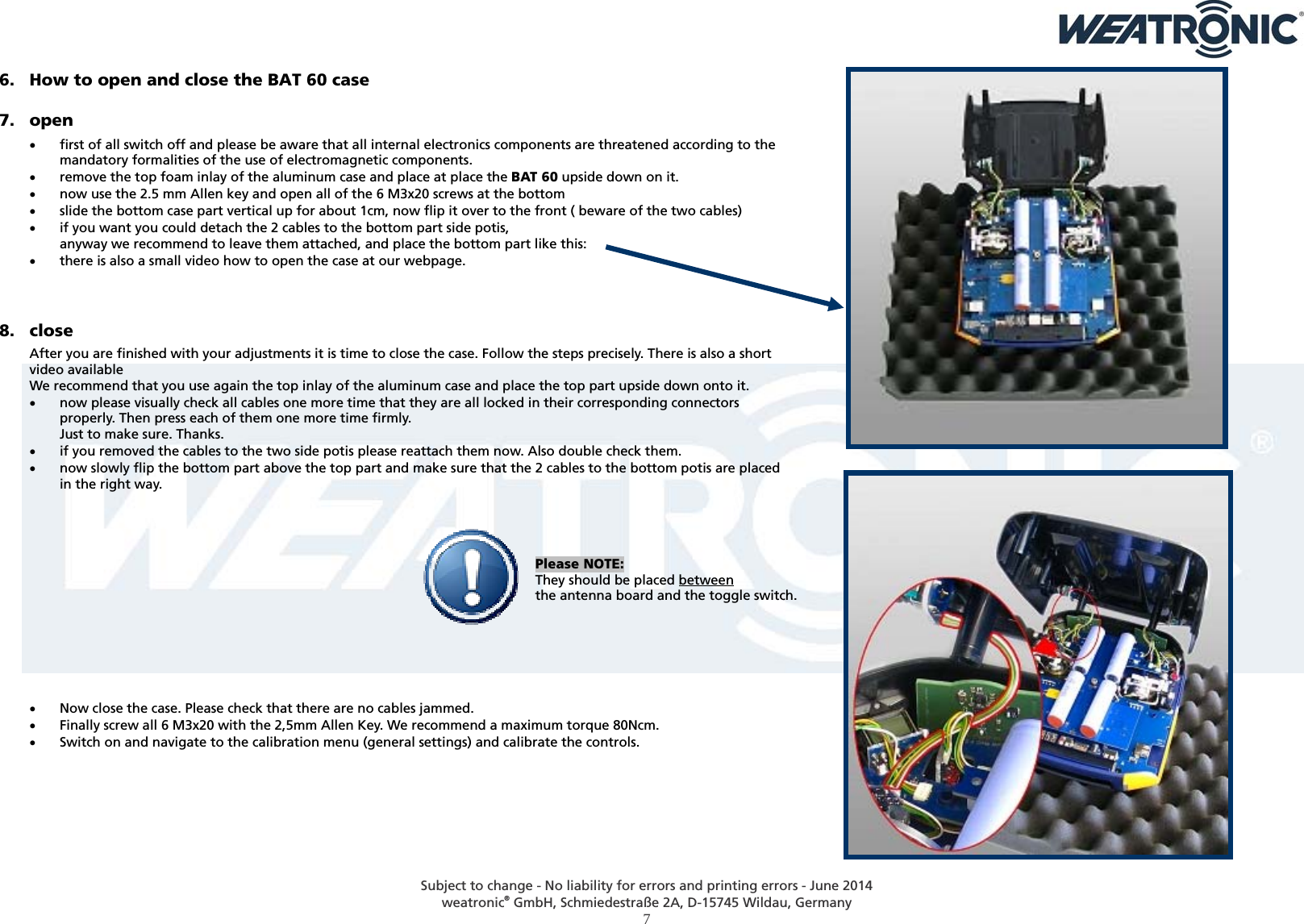
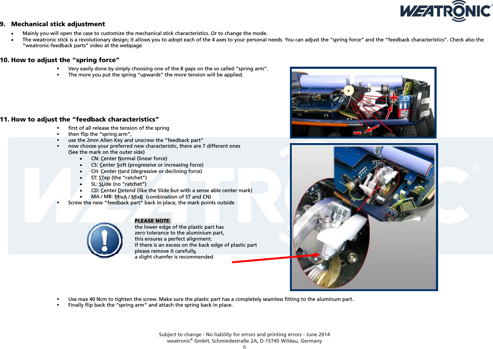
User Manual
Discussion / Help
Navigation