Weatronic 2754-60 FHSS Equipment User Manual
Weatronic GmbH FHSS Equipment
User Manual
Subject to change - No liability for errors and printing errors - June 2014
weatronic® GmbH, Schmiedestraße 2A, D-15745 Wildau, Germany
1
User Manual
Introduction
The Development, production and assembly of all weatronic products is based in Germany. All components are tested with the highest German standards. During the development process reliability
and noise immunity are considered the most.
Please always check www.weatronic.com for more information about the BAT 60. Under the section support videos you will find all the small videos mentioned here in this manual.
“MADE IN GERMANY”
Content:
1.scope of supply ................................................................................... 2
2.Type approvals .................................................................................... 2
2.1.FCC ................................................................................................. 2
2.2.IC Canada ..................................................................................... 2
2.3.CE R&TTE ...................................................................................... 3
2.4.Intended use ................................................................................ 3
2.5.safety instructions ...................................................................... 3
3.Care instructions ................................................................................. 4
4.General overview ............................................................................... 5
5.Overview about internal electronics .............................................. 6
6.How to open and close the BAT 60 case ....................................... 7
7.open ....................................................................................................... 7
8.close ....................................................................................................... 7
9.Mechanical stick adjustment ........................................................... 8
10.How to adjust the “spring force” ................................................... 8
11.How to adjust the “feedback characteristics” ............................. 8
12.Mechanical toggle switch adjustment ......................................... 10
13.Hardware extras ............................................................................... 11
14.BAT 60 power supply (10 - 19 Volt) .............................................. 11
15.LED status information ................................................................... 11
16.Transmitter is switched off and charging: .................................. 11
17.Transmitter is switched on: ............................................................ 11
18.How to switch on/off ....................................................................... 12
19.ON ........................................................................................................ 12
20.OFF ....................................................................................................... 12
21.RESET ................................................................................................... 12
22.interface ............................................................................................. 13
22.1.The screen .................................................................................. 13
22.2.Common interface icons ....................................................... 14
22.3.Common interface symbols ................................................... 15
23.Calibration of potentiometers and sticks ................................... 16
24.UPDATE ............................................................................................... 16
24.1.update process of BAT 60 ....................................................... 16
24.2.update of weatronic Receivers ............................................. 16
25.Binding process ................................................................................. 16
26.RC-equipment installations in your model ................................ 16
27.How to add new model: ................................................................. 17
27.1.1st step: model configuration: ............................................... 17
27.2.2nd step: receiver configuration: ........................................... 17
27.3.3rd step: servo configuration graphic ................................... 17
27.4.4th step: servo configuration list: .......................................... 17
28.weatronic programming philosophy ........................................... 18
29.Disclaimer of warranty / damages ............................................... 19
30.Disposal instructions for countries within the EU .................... 19
Subject to change - No liability for errors and printing errors - June 2014
weatronic® GmbH, Schmiedestraße 2A, D-15745 Wildau, Germany
2
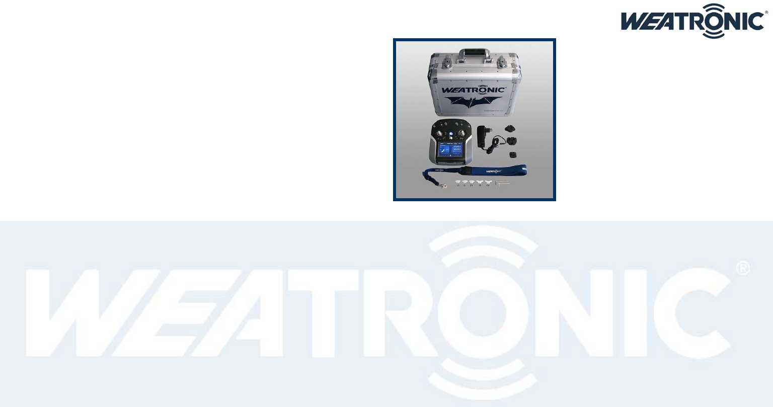
1. scope of supply
BAT 60 ( 4 different colors schemes are available: white / black / silver / weatronic )
Aluminum case with foam inlay
Switching Power Supply with UK/US/EU/AU adapter
Allen key set
Feedback parts standard set ( ST SL CD CS CH one of each )
Neck strap
2. Type approvals
Hereby the weatronic ® GmbH declares that the BAT 60 transmitter applies to the requirements and other relevant provisions of the relevant CE directive. A copy of the declaration of conformity and
the ETSI and FCC certification can be downloaded at our homepage. (www.weatronic.com) The BAT 60 has been designed, tested and certified according to international standards as follows :
2.1. FCC
FCC intentional radiator certification
FCC ID: W3X2754-60 for weatronic BAT60 (handheld transmitter) radio control system.
This equipment contains an intentional radiator approved by the FCC under the FCC ID numbers shown above. This device complies with Part 15 of the FCC Rules. Operation is subject to the following
two conditions:
This device may not cause harmful interference and
This device must accept any interference received, including interference that may cause undesired operation.
2.2. IC Canada
EMC compliance Canada
UPN : 11388A-600
This device complies with Industry Canada licence-exempt RSS standard(s). Operation is subject to the following two conditions:
this device may not cause interference and
this device must accept any interference, including interference that may cause undesired operation of the device.
Cet appareil est conforme à la norme RSS Industrie Canada exempt de licence. Son fonctionnement est soumis aux deux conditions suivantes:
cet appareil ne doit pas provoquer d’interférences et
cet appareil doit accepter toute interférence, y compris les interférences pouvant causer un mauvais fonctionnement du dispositif.

Subject to change - No liability for errors and printing errors - June 2014
weatronic® GmbH, Schmiedestraße 2A, D-15745 Wildau, Germany
3
2.3. CE R&TTE
EMC compliance Europe
This equipment meets the requirements of the R&TTE and EMC directives. CE Conformity. This equipment has been developed and constructed in conformance with the current CE regulations and
guidelines:
2006/42/EC Machine Directive
2006/95/EC Low Voltage Directive
2004/108/EC EMC Directive
1999/5/EC R&TTE Directive
Article 3.1(a) Health EN 62311:2008 Report 13/1416
Article 3.1(a) Safety EN 60950-1:2006 +A11:2009 + A1:2010 +A12:2011 Report 13/1414
Article 3.1(b) EMC ETSI EN301 489 -1: V1.9.2 (2011-09) ETSI EN301 489-17: V2.2.1 (2012-09) Report 13/1415
Article 3.2 Radio ETSI EN300 328 V1.8.1 (2012-06)
2.4. Intended use
The weatronic BAT60 transmitter radio control system consists of modular components. The system is designed for exclusive use of remote controlled airplane models, model ships and cars and other
models.
2.5. safety instructions
The weatronic BAT60 transmitter radio control system is a complex system requiring strict observance of relevant safety rules and guidelines. Before working with the weatronic RC system, ensure that
you are familiar with the system and its operating parts and with the specific safety instructions included in this manual. The weatronic® 2.4 Dual FHSS - Remote Control System has been developed
exclusively for the operation of radio-controlled model cars, model aircraft and ship models and is only allowed for this use. weatronic® assumes no liability for improper use. Young people under
14 years may operate remote controlled models only under adult supervision. Please operate your model only on intended areas. Be considerate to other pilots and arrange with each other. Stay in
reach to other pilots, so you can communicate about your landings and take-offs approaches in order to avoid accidents. Always stay away from Non-Fly zones and never fly over spectators or any
persons who are near the airfield. The weatronic® 2.4 Dual FHSS system can be used simultaneously with other 2.4 GHz systems, and also with 35/40/72 MHz systems. The frequency control check is no
longer necessary within the 2.4GHz band. More than 120 weatronic® 2.4 Dual FHSS systems can simultaneously be operated.
Before operation always perform the following routine checks: fix your model in place. Keep a safe distance. Mind spectators, especially spectators who are not aware of the potential dangers! Indicate
sources of danger, such as rotating blades and propellers or the hot exhaust of jet-turbines, etc. First of all switch on your transmitter. Then turn on the receiver. All functions of the model, in particular
their moving direction and all surface deflections should be checked. Also check your batteries to be sufficiently charged.
This manual describes potential hazards you may encounter during operation of this product, but we cannot predict all possible hazards. Safety messages included in this manual may not represent an
exhaustive list, and the guidelines included in this manual should be applied using your judgment and experience. Prior to using this equipment, read and observe all safety information and instructions
included in this manual. If you are unsure about any of the potential hazards discussed, contact your dealer or importer immediately.
Read, understand, and follow all safety information contained in these instructions before using your weatronic BAT60 radio control system. Retain these instructions for future reference.
Subject to change - No liability for errors and printing errors - June 2014
weatronic® GmbH, Schmiedestraße 2A, D-15745 Wildau, Germany
4
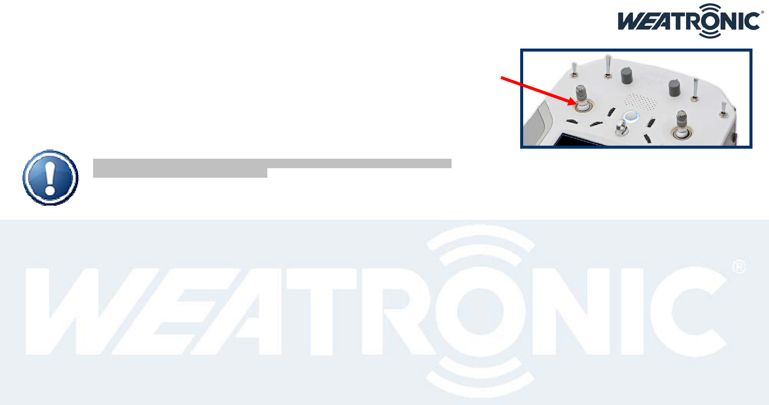
3. Care instructions
Please use a soft and damp cloth for cleaning the case and the display.
Also we recommend keeping the center metal ball of the stick clean. Usually you don’t need to oil the stick! However we
recommend using a very tiny amount of synthetic lubricant which does not resinify or polymerize. Please use a cloth and apply a
tiny portion. Call us if you have any questions.
Whenever the radio is used in humid air please let it dry properly before switching it on again.
if your BAT 60 got somehow wet inside or outside please switch it off and let it dry before switching it on again.
keep your BAT 60 clean, dry and avoid dusty environment.
do not block the antennas with any kind of electro conductive material, this includes also parts of the human body. The two
independent antennas are located underneath the black front cover.
Please NOTE: Many components of your radio could be influenced by magnetic waves.
So please keep away any strong magnets.
Subject to change - No liability for errors and printing errors - June 2014
weatronic® GmbH, Schmiedestraße 2A, D-15745 Wildau, Germany
5
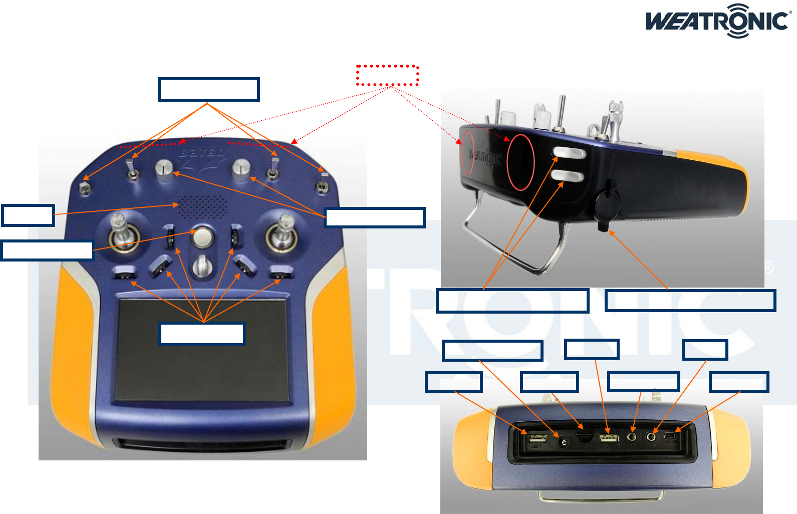
4. General overview
REAR VIEW
SIDE VIEW
TOP VIEW
US
B
„
1“
D
C
in
(
1
0
-1
9
V
o
l
t
)
mini
US
B
US
B
„
2“
PPM
(
in
/out)
Audio
mi
c
r
o
S
D
T
O
P P
ote
n
t
i
o
m
ete
r
SIDE Potentiometer
(
left and ri
g
ht
)
Rocker Switches (left and right)
Toggle Switches
O
N
/
O
FF B
utto
n
Rotary Encoder
S
p
eaker
An
te
nn
as
Subject to change - No liability for errors and printing errors - June 2014
weatronic® GmbH, Schmiedestraße 2A, D-15745 Wildau, Germany
6
BATTERYBOARD
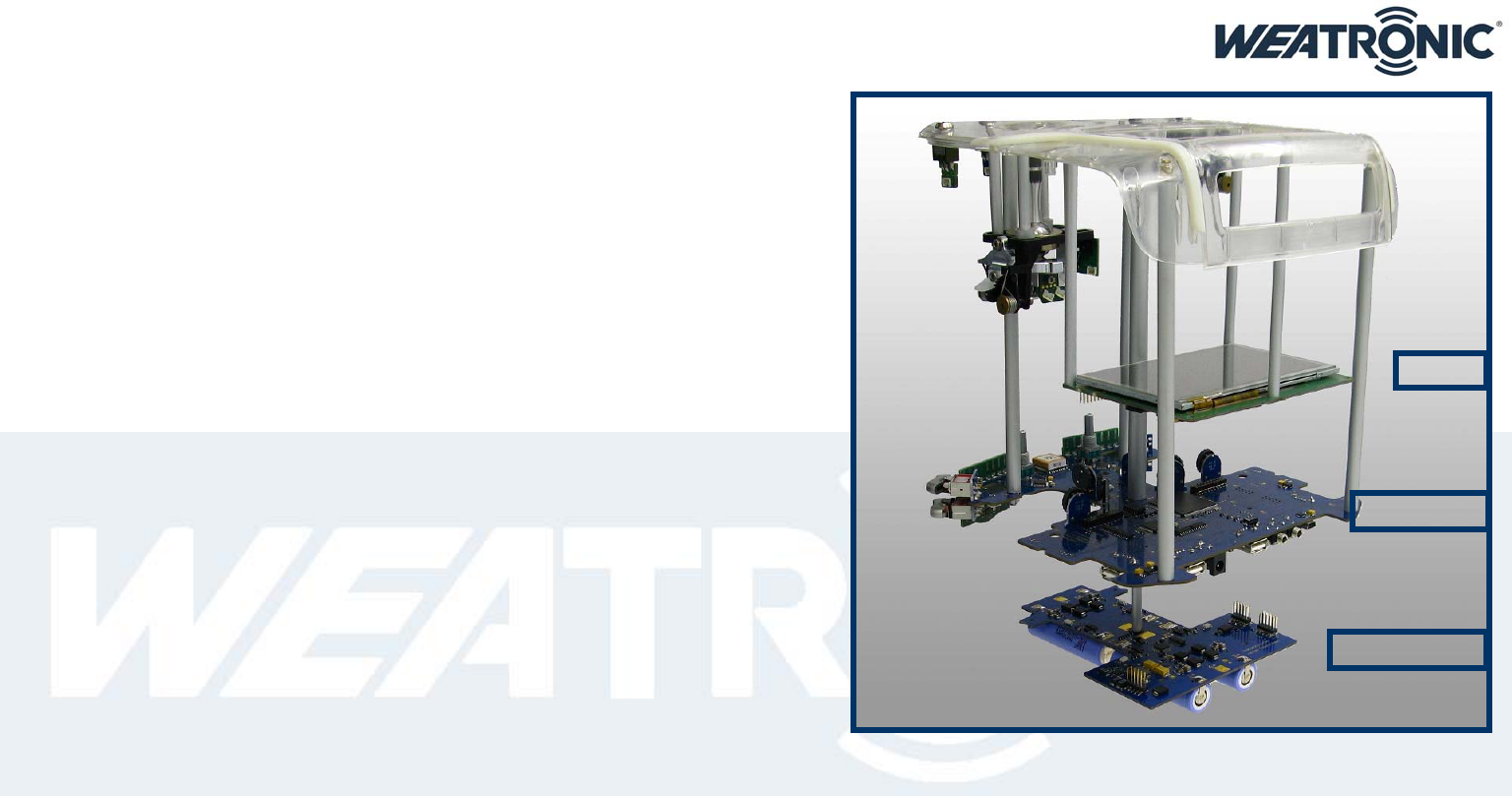
5. Overview about internal electronics
There are 3 main electronic PCBs (printed circuit boards)
o the Mainboard is the biggest one and there are several small PCB soldered to it. Like the
Antennas and the rotary encoder PCB and the front switches. The Mainboard takes care about
the transmission and is the most important component.
o the Battery Board takes care about the LiIon cells. It contains a charger and capacity surveillance
for each cell.
o The Linux / Display board (called LinDis ) contains the Linux computer which provides the
interface to the User! Anyhow it is not necessarily needed to operate the BAT 60.
Also there are some more additional smaller PCBs
o The stick includes 2 hall sensor boards. The internal and the external one. The cable connection
to the Mainboard is the most significant cable connection inside the BAT 60.
o There are some small PCBs at each toggle switch and at the two side potentiometers in the
bottom case.
LINDI
S
MAINBOARD
Subject to change - No liability for errors and printing errors - June 2014
weatronic® GmbH, Schmiedestraße 2A, D-15745 Wildau, Germany
7
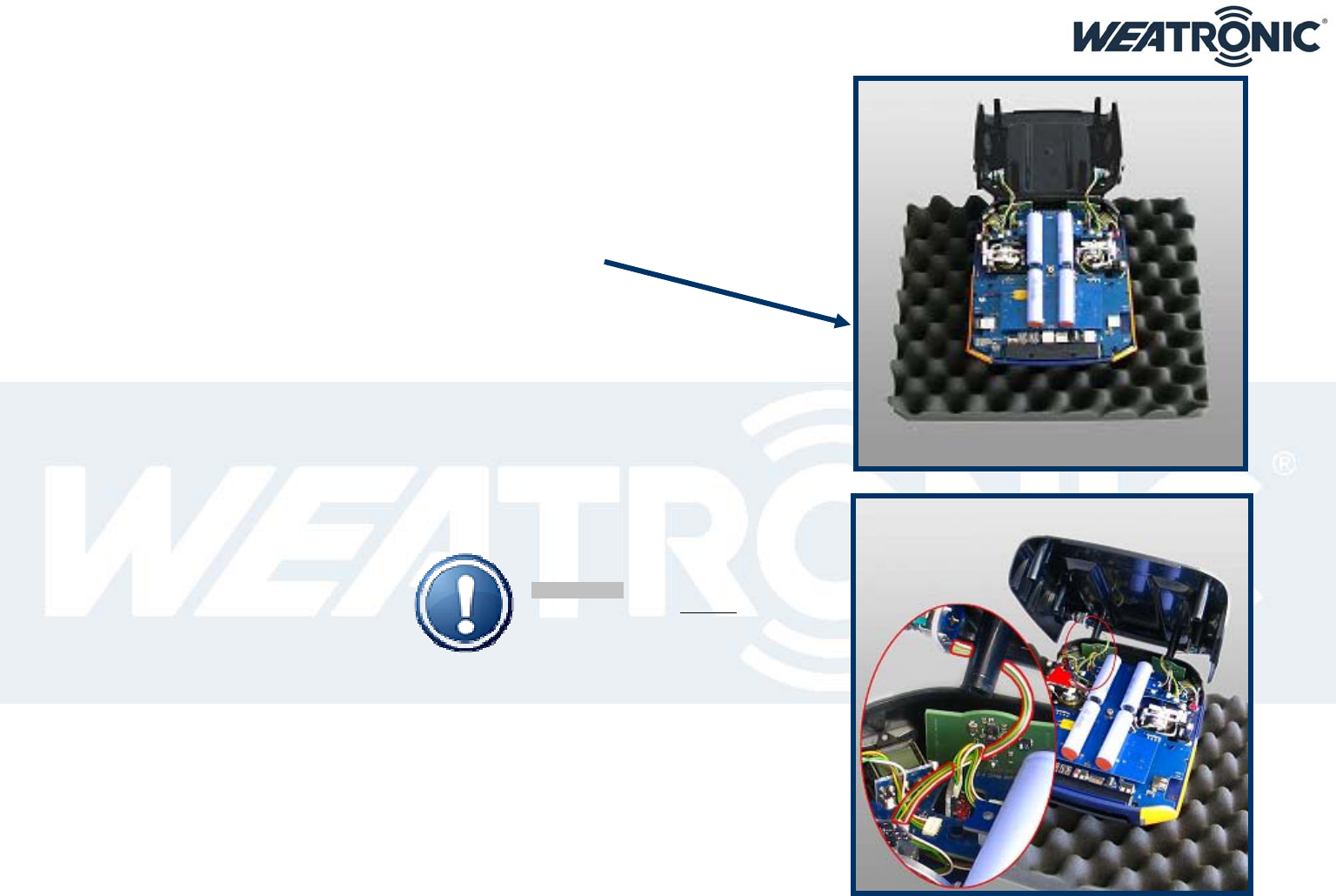
6. How to open and close the BAT 60 case
7. open
first of all switch off and please be aware that all internal electronics components are threatened according to the
mandatory formalities of the use of electromagnetic components.
remove the top foam inlay of the aluminum case and place at place the BAT 60 upside down on it.
now use the 2.5 mm Allen key and open all of the 6 M3x20 screws at the bottom
slide the bottom case part vertical up for about 1cm, now flip it over to the front ( beware of the two cables)
if you want you could detach the 2 cables to the bottom part side potis,
anyway we recommend to leave them attached, and place the bottom part like this:
there is also a small video how to open the case at our webpage.
8. close
After you are finished with your adjustments it is time to close the case. Follow the steps precisely. There is also a short
video available
We recommend that you use again the top inlay of the aluminum case and place the top part upside down onto it.
now please visually check all cables one more time that they are all locked in their corresponding connectors
properly. Then press each of them one more time firmly.
Just to make sure. Thanks.
if you removed the cables to the two side potis please reattach them now. Also double check them.
now slowly flip the bottom part above the top part and make sure that the 2 cables to the bottom potis are placed
in the right way.
Please NOTE:
They should be placed between
the antenna board and the toggle switch.
Now close the case. Please check that there are no cables jammed.
Finally screw all 6 M3x20 with the 2,5mm Allen Key. We recommend a maximum torque 80Ncm.
Switch on and navigate to the calibration menu (general settings) and calibrate the controls.
Subject to change - No liability for errors and printing errors - June 2014
weatronic® GmbH, Schmiedestraße 2A, D-15745 Wildau, Germany
8
9. Mechanical stick adjustment
Mainly you will open the case to customize the mechanical stick characteristics. Or to change the mode.
The weatronic stick is a revolutionary design; it allows you to adopt each of the 4 axes to your personal needs. You can adjust the “spring force” and the “feedback characteristics”. Check also the
“weatronic-feedback parts“ video at the webpage
10. How to adjust the “spring force”
Very easily done by simply choosing one of the 8 gaps on the so called “spring arm”.
The more you put the spring “upwards” the more tension will be applied.
11. How to adjust the “feedback characteristics”
first of all release the tension of the spring
then flip the “spring arm”,
use the 2mm Allen Key and unscrew the “feedback part”
now choose your preferred new characteristic, there are 7 different ones
(See the mark on the outer side)
CN: Center Normal (linear force)
CS: Center Soft (progressive or increasing force)
CH: Center Hard (degressive or declining force)
ST: STep (the “ratchet”)
SL: SLide (no “ratchet”)
CD: Center Detend (like the Slide but with a sense able center mark)
MA / MB: MixA / MixB (combination of ST and CN)
Screw the new “feedback part” back in place, the mark points outside
PLEASE NOTE:
the lower edge of the plastic part has
zero tolerance to the aluminium part,
this ensures a perfect alignment.
If there is an excess on the back edge of plastic part
please remove it carefully,
a slight chamfer is recommended
Use max 40 Ncm to tighten the screw. Make sure the plastic part has a completely seamless fitting to the aluminum part.
Finally flip back the “spring arm” and attach the spring back in place.
Subject to change - No liability for errors and printing errors - June 2014
weatronic® GmbH, Schmiedestraße 2A, D-15745 Wildau, Germany
9
PLEASE NOTE:
The cables to the Stick PCBs are very important!
Please always check a proper locking of the cables
to the connectors and also make sure that
the cables are placed in the right way! See the picture:
Whenever you encounter any issues or any visual damage
to one of the cables or the stick itself do NOT fly
and contact our service. Never modify the stick in any way!
Subject to change - No liability for errors and printing errors - June 2014
weatronic® GmbH, Schmiedestraße 2A, D-15745 Wildau, Germany
10
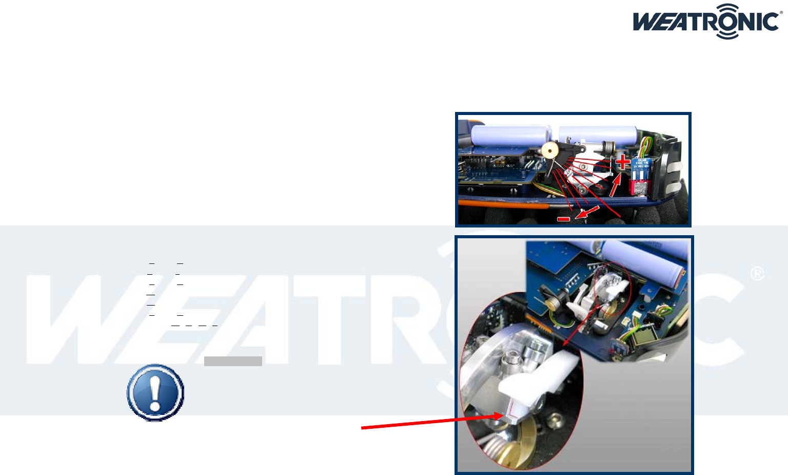
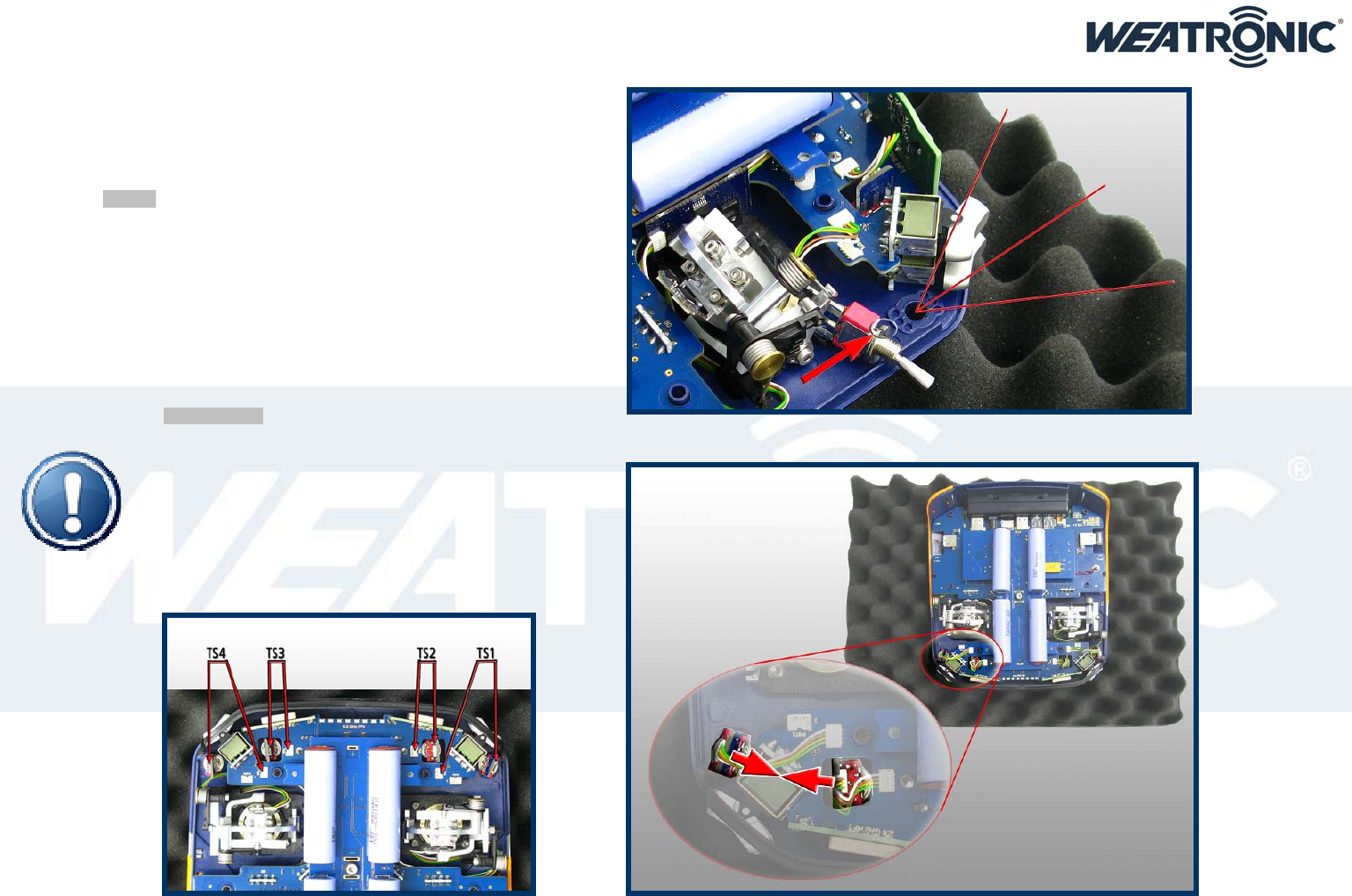
12. Mechanical toggle switch adjustment
You can customize the 4 top toggle switches
o There are different ones available,
please check our web shop for detail information
o You can apply 3 angular positions to each switch
o Just choose one of the 3 positions on the case.
Use a 9mm wrench to mount the dress nut.
PLEASE be careful, hand-tight is enough! The pin which
prevents the switch to turn can be easily damaged.
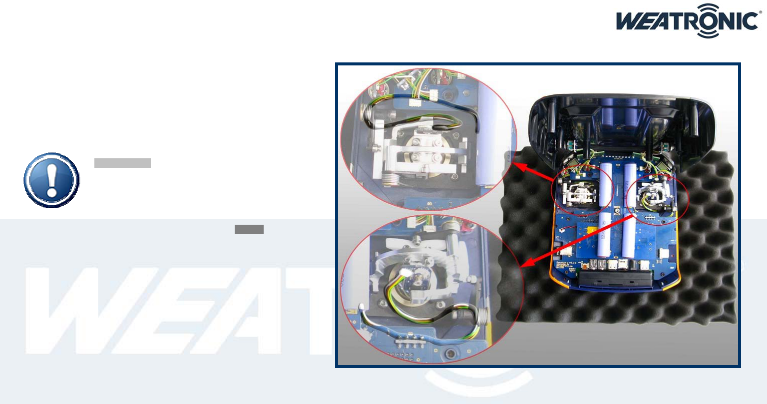
PLEASE NOTE:
The backside (lettering is on the backside) of the 2 left
(or the 2 right) Switch mini boards should point to each other!
Also make sure that the cables are not twisted and the
connectors are placed right!
The length of the cable is 50mm.

Subject to change - No liability for errors and printing errors - June 2014
weatronic® GmbH, Schmiedestraße 2A, D-15745 Wildau, Germany
11
13. Hardware extras
The BAT 60 can be upgraded with some really nice features.
There is the option to install a vibration motor, which can be used to indicate warnings or simple information. Please note that the vibration does not come with your default BAT 60.
There is also an option to install a Bluetooth chip to the Main Board. This will be available as an option later.
The Wi-Fi dongle will be already as a standard and connects your BAT 60 to any Wi-Fi network. If your BAT60 is connected to the same network as your PC you will be able to log in to the radio via
your browser and program simultaneous from both devices. We recommend that you use one of the devices as the “main” programming input and the “second” one as a control display. Because it
will be confusing if you change values for one “item” from 2 different sources. Please consider the detailed instruction at our webpage.
14. BAT 60 power supply (10 - 19 Volt)
The BAT 60 handheld radio is equipped with 4 Li-Ion cells which are maintained and charged by an internal charge controller. This controller checks temperature, voltage, current, and calculates the
capacity of each cell. Also it takes care about the entire charge process. Whenever there is a voltage between 10 and 19 Volts applied to the power jack the controller starts to charge the cells.
In order to charge your BAT 60 easily attach the switching power supply which is provided with your radio. Car adapters could be obtained from our shop.
Under “General Settings” you will find the battery management menu and there you can check the status of all cells.
PLEASE NOTE: charging during operation/flight is no problem.
15. LED status information
The LED ring around on/off button shows you some basic system status:
16. Transmitter is switched off and charging:
o Green: fully charged
o Orange: more than 80% charged
o Red: <80% charged
o Red blinking: recovering of low battery status
17. Transmitter is switched on:
The slow continuous blinking shows the state of the BAT 60 batteries:
o Blue: more than 20% remaining
o Orange: less than 20% remaining capacity
o Red: less than 10% remaining capacity
o Red rapid flashing: Running on spare!
The short red blink codes in between show Rx status:
o Nothing: everything Ok
o 1x red: return channel threshold warning
o 2x red: uplink threshold warning
o 3x red: low battery threshold warning

Subject to change - No liability for errors and printing errors - June 2014
weatronic® GmbH, Schmiedestraße 2A, D-15745 Wildau, Germany
12
18. How to switch on/off
19. ON
Press the on/off button will activate the BAT 60 and will start the boot process of the Linux PC. The booting of the Linux will take some seconds.
Nevertheless you can fly with the last used model within less than one second with all settings, Flight modes, etc.
Linux boot is finished when you see the home screen. Now you can do changes on the settings, change model, etc…
20. OFF
Tab the Off symbol at the navigation row or press the ON-OFF button longer then 3 seconds.
Now confirm the notification pop up by pressing the ON-OFF button once.
21. RESET
Press the ON/OFF button for at least 10 seconds, the LED around the button will start to flash rapidly green.
Now release the button and the LED will change the color to red. Now you have 3 seconds to press the button again and the BAT 60 will turn off.
PLEASE NOTE: consider that there may other status information indicated by the LED. They may be interfering with the rapid green or red flashing.
Subject to change - No liability for errors and printing errors - June 2014
weatronic® GmbH, Schmiedestraße 2A, D-15745 Wildau, Germany
13
22. interface
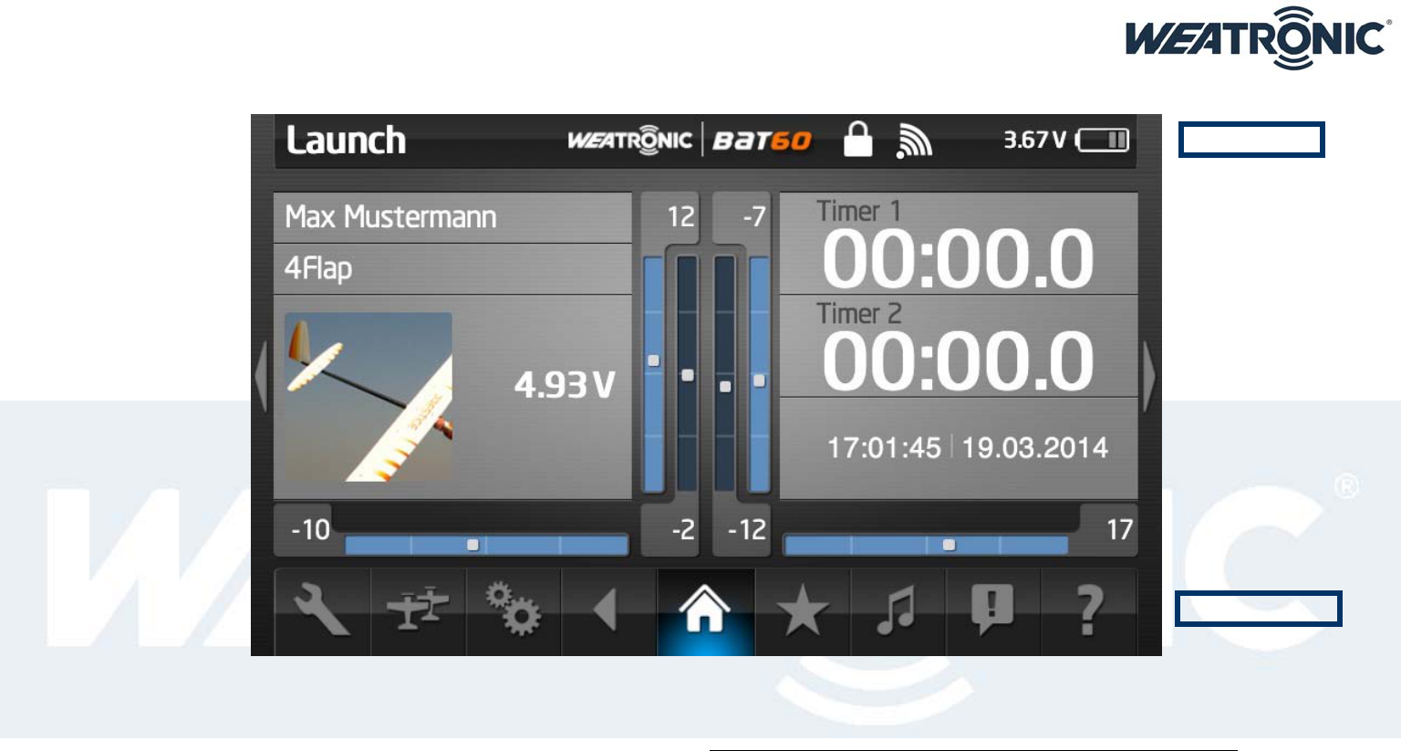
Here you see the home screen:
22.1. The screen
The screen of BAT 60 is a capacitive touch screen. This means it recognizes the presence of your finger. Pressing hard on the screen will not improve functionality but reduce lifetime. Furthermore it will
not recognize any metal, wood, plastics, etc. If you don’t want to use finger for touch please buy a special pen for capacitive touch screens.
TOP INFO ROW
NAVIGATION ROW
Subject to change - No liability for errors and printing errors - June 2014
weatronic® GmbH, Schmiedestraße 2A, D-15745 Wildau, Germany
14
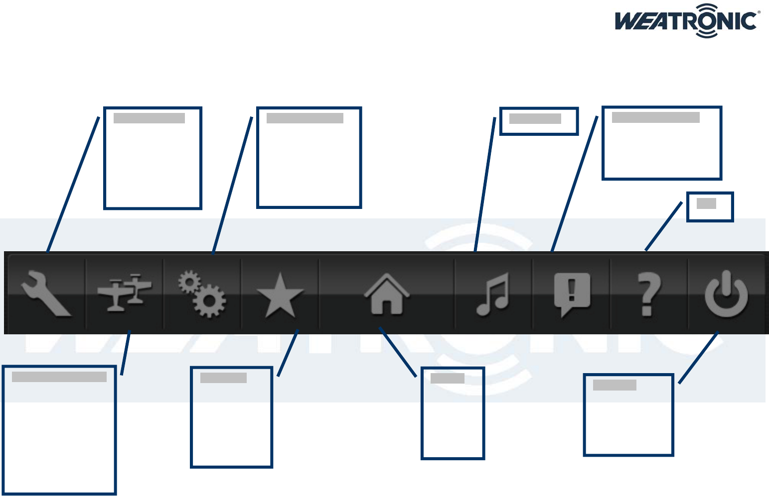
22.2. Common interface icons
The info row on top of the screen always tells you about the current model, flight mode as well as the remaining expected runtime. The battery symbol on the top right corner gives evidence about the
battery status
The navigation row on the bottom is used for all setup.
“model settings”
This is the model
specific setting,
saved in the
model memory
and therefore can
be different for
every model.
“general settings”
This is concerning
the general setting
on the Transmitter.
Therefore settings
done here are the
same for every
model.
“model management”
Here you get access to
the model memory,
change the current
model, add a new one
or use the
import/export
function. Also you can
filter by type or
category or the check
model info.
“home”
Tabbing
here will
take you
back to
home
screen
“favorites”
In this menu
you can have
your favorites
as short link to
any page in
the user
interface.
“Turn off”
Here turn off
Bat 60. Abort on
the display or
confirm via
on/off button
Music Player “notification center”
Here you get
information about
happenings and
warnings during flight.
Help
Subject to change - No liability for errors and printing errors - June 2014
weatronic® GmbH, Schmiedestraße 2A, D-15745 Wildau, Germany
15
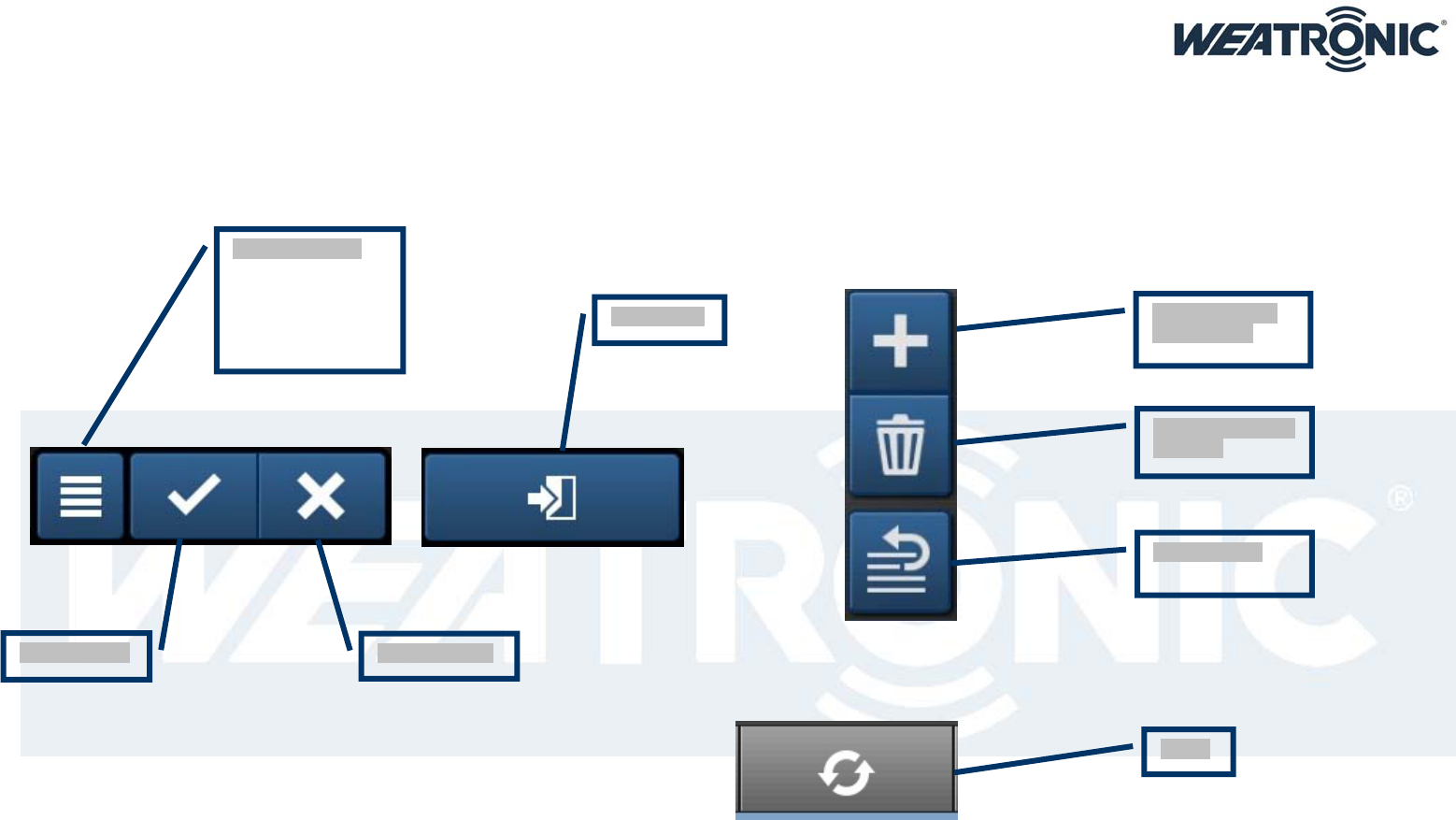
22.3. Common interface symbols
There are some common symbols used for navigation through the interface:
“Additional info”
(short link to servo
monitor, control
map, add page to
favorites menu,
help)
Save settings:
Leave page:
Abort settings:
Add something
new to a list:
Delete something
from list:
Reorder a list:
UNDO

Subject to change - No liability for errors and printing errors - June 2014
weatronic® GmbH, Schmiedestraße 2A, D-15745 Wildau, Germany
16
23. Calibration of potentiometers and sticks
Go to general settings -> calibration.
Press “start calibration”.
All moved controls are shown in red and their maximum position reached during this process will be adapted to +/- 100%.
After this press “learn center”. The position of all red marked controls in the moment of pressing “finish calibration” will be adapted to 0%.
Also you have the possibility to set a center deadband:
Go to general settings -> center deadband.
Set the center deadband for the controls shown on the list.
24. UPDATE
24.1. update process of BAT 60
Go to our download center and copy the weatronic folder to a formatted USB stick. Insert the USB stick to one of the external USB ports at your BAT 60. Now switch on and wait until the Home screen
appears. Now go to general settings -> firmware versions and check if the right version is displayed.
24.2. update of weatronic Receivers
Check the weatronic-firmware update instruction.
Please Note that the BAT 60 requires a matching firmware version for the receiver. Go to weatronic.com and download the current one.
25. Binding process
Before binding process please check that there is a matching firmware installed to the receiver.
To bind a receiver to the Bat 60 set the Rx to binding mode. Therefore have it in power off state, then connect power supply. In between 5-30sec after power up plug the binding jumper to the SCU
red(+) and black (-). The Rx will confirm Binding mode by slow blinking of green LED.
Now navigate to the Receiver configuration menu. Choose your correct receiver type. Press “binding” button. The flying bat shows you that binding is in progress. After successful binding the bat will
disappear and the firmware version of the Rx will be shown on the screen. Also the Rx will confirm successful binding with constant green LED.
Remove the Binding jumper – finished.
Please NOTE: only weatronic receivers can work with the BAT 60.
26. RC-equipment installations in your model
The correct installation of the receiver, battery, servos, electric cables and antennas is required to operate your model.
Avoid excessive vibration exposure and excessive heat stress.

Subject to change - No liability for errors and printing errors - June 2014
weatronic® GmbH, Schmiedestraße 2A, D-15745 Wildau, Germany
17
27. How to add new model:
Navigate to Model management and tab on add new model.
Then choose the type of your model. The category glider also includes gliders with “engine” or “up and go” engine. Boat and car would be free model.
The wizard guides you through the setup process.
27.1. 1st step: model configuration:
Here you can set up a model name, add an image, select a category for filtering on model management, and add an info text for checklist, maintenance, general purpose…
The resolution for showing and adjusting values can be set to steps of 1% or 0,1%
The function preselect will define the way you get a preselected list of functions:
o None: No functions will be predefined
o Basic: all functions to setup the model for general purpose use will be predefined
o Advanced: the predefined functions will give all possibilities for expert user and highly sophisticated setup
Then you set up the geometric specifications of your model. For helicopters this is the configuration of the swashplate and the gyro and mixing system you use. For planes the tail type or
only wing configuration as well as the numbers of control surfaces.
27.2. 2nd step: receiver configuration:
Here you can choose and bind the receiver (see chapter 15 ) for your model as well as adjust some basic setup.
We recommend that you adjust the right voltage warning especially for battery according to the circumstances in your model.
Also you can add sub receivers. They can be used as parallel receiver but also for extending the number of servo plugs. NOTE: Only the main Rx is capable of handling additional telemetry and
sensors.
27.3. 3rd step: servo configuration graphic
In this menu you tell the BAT 60 everything about the servos used and their location in your plane.
Just add the servos to the control surfaces and set up name, center and limits properly.
27.4. 4th step: servo configuration list:
This is the list of all your servos. Here you see again the setup of the graphic view but also can configure the servos that are not handled via graphic view.
After this the wizard will finish and create a model and functions according to your settings.
Please make sure all adjustments are done properly as some parts like
function preselect,
tail type,
number of control surfaces,
…
can not be changed afterwards.
Subject to change - No liability for errors and printing errors - June 2014
weatronic® GmbH, Schmiedestraße 2A, D-15745 Wildau, Germany
18
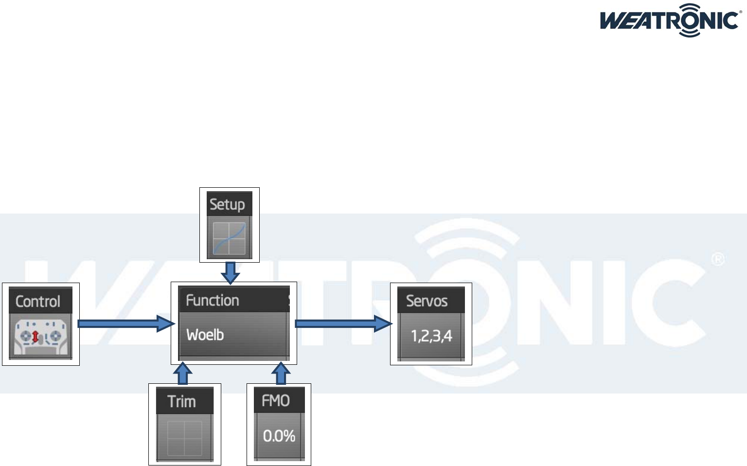
28. weatronic programming philosophy
With the weatronic programming style you are no longer limited to channels or predefined and fix structures.
The model setup is organized in functions. These could be i.e. aileron, elevator, etc. as you can choose the name yourself.
Usually each Function needs one control i.e. one stick axis, switch, etc. to operate during flight
Then you assign the servos to each function and set the dedicated maximum travel according to your wishes, mechanical or aerodynamic requirements.
Afterwards you can change your functions with all the assigned servos under function setup. There you set up values like expo, rate, curve, differential (NOTE: for correct function of differential your
servos need to have correct L(eft) R(ight) attribute)
We strongly recommend that you adjust proper failsafe for each function. At least engine cut off to avoid any danger or hazardous risks.
When necessary you can add a Trim or a constant (flight mode-) offset (FMO)
See this diagram:

Subject to change - No liability for errors and printing errors - June 2014
weatronic® GmbH, Schmiedestraße 2A, D-15745 Wildau, Germany
19
29. Disclaimer of warranty / damages
weatronic® complies with the statutory requirements granted a 24-month warranty.
To assert a warranty claim the corresponding article should be sent to the seller
For processing the warranty claims
proof of purchase,
detailed description of the damage and
log files of the accident
are needed.
weatronic® will not issue warranty or guarantee for:
improper operation,
mechanical changes,
polarity and external surges,
short circuits,
overheating.
weatronic® assumes no responsibility for any loss, damage or expense arising out of incorrect use and operation, including any kind of resulting consequence.
As far as legally allowed, the commitment of the weatronic ® GmbH to pay damages, for whatever legal reason, is limited to the invoice value of the directly involved and damage-causing goods of the
weatronic® GmbH.
30. Disposal instructions for countries within the EU
Inside the European Union the weatronic ® Transmitter BAT 60 must be disposed separated of the household waste by end of its service life Proper disposal information can be obtained by the local
authorities.
Wildau, 17/06/2014
weatronic GmbH
Schmiedestraße 2A
15745 Wildau
GERMANY
Telephone: +49 (0) 3375 24 60 89 - 0
Telefax: +49 (0) 3375 24 60 89 - 1
E-Mail: info@weatronic.com
www.weatronic.com