Weider 15601 User Manual POWER GYM SINGLE STATION HOME Manuals And Guides L1003308
WEIDER Misc Exercise Manual L1003308 WEIDER Misc Exercise Owner's Manual, WEIDER Misc Exercise installation guides
User Manual: Weider 15601 15601 WEIDER POWER GYM SINGLE STATION HOME GYM - Manuals and Guides View the owners manual for your WEIDER POWER GYM SINGLE STATION HOME GYM #15601.
Open the PDF directly: View PDF ![]() .
.
Page Count: 24
15601 SINGLE STATION
I
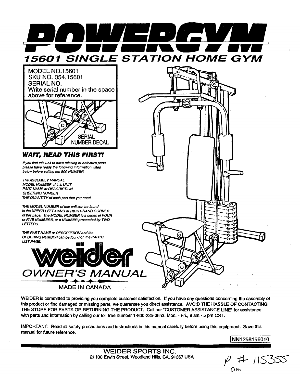
MODEL NO.15601
SKU NO. 354.15601
SERIAL NO.
Write serial number in the space
above for reference.
HOME GYM
WArt, READ THIS FIRST!
ff you find this unit to have missing or defective parts
please have ready the fol/owing information listed
below before calling the 800 NUMBER,
The ASSEMBL Y MANUAL
MODEL NUMBER of this UNIT
PART NAME or DESCRIPTION
ORDERING NUMBER
THE QUANTITY of each part that you need.
THE MODEL NUMBER of this unit can be found
In the UPPER LEFT-HAND or RiGHT-HAND CORNER
of this page. The MOOEL NUMBER is 8series of FOUR
or FIVE NUMBERS, or aNUMBER preceeded by TWO
LETTERS.
THE PART NAME or DESCRIPTION and the
ORDERING NUMBER can be found on the PARTS
US T PAGE.
0 WNER'S MANUAL
MADE .IN CANADA
WELDERis committedto providingyou completecustomersatisfaction.If youhave any questionsconcerning the assemblyof
this productor finddamaged ormissingparts,we quaranteeyoudirectassistance. AVOID THE HASSLE OF CONTACTING
THE STORE FOR PARTS OR RETURNING THE PRODUCT. Call our "CUSTOMER ASSISTANCE UNE" for assistance
withpartsandinformationby callingour tollfree number1-800-225-0653, Mon.- Fri., 8 am-5 pm CST.
IMPORTANT: Read allsafety precautionsand instructionsin thismanualcarefully before usingthis equipment.Save this
manualforfuture reference.
1NN1258156010]
WELDER SPORTS INC.
21100 Erwin Street, Woodland Hills, CA. 91367USA F _" I)_"3_"_
On
PAGE 1 wEiDER SPORTING GOODS
TABLE OF _CONTENTS
Table of Contents ................................. 1
Important Safety Precautions ..................... 1
Introduction ....................................... 2
Assembly Steps ................................ 6-22
Maintenance Tips ................................... 2
Conditioning Guide ............................. 23
Parts List ....................................... 3-4
Ordering Parts ................................. 5
IMPORTANT SAFETY PRECAUTIONS _'
WARNING: +o reduce the risk of serious Injury, read the important safety precautions before using this
equipment.
1. Read all Instructions in this manual before using this equipment.
2. Use this equipment only as described tn this Owner's Guide.
3. Inspect and tighten all parts each time this equipment is used. Replace any worn parts Immediately.
4. Keep hands away from moving parts other than the designated handles.
+
5. Keep small children away from this equipment during use.
WARNING: Before beginning this or any exercise pro_lram consult your physician. This is especially
Important for individuals over the age of 35 or persons with pre-ex=sting health problems. Read all instructions
before using. Welder assumes no responsibility for personal Injury or property damage sustained by or through the
use of this product.
+' SAVE THESE INSTRUCTIONS
PAGE 2WELDER SPORTING GOODS
INTRODUCTION
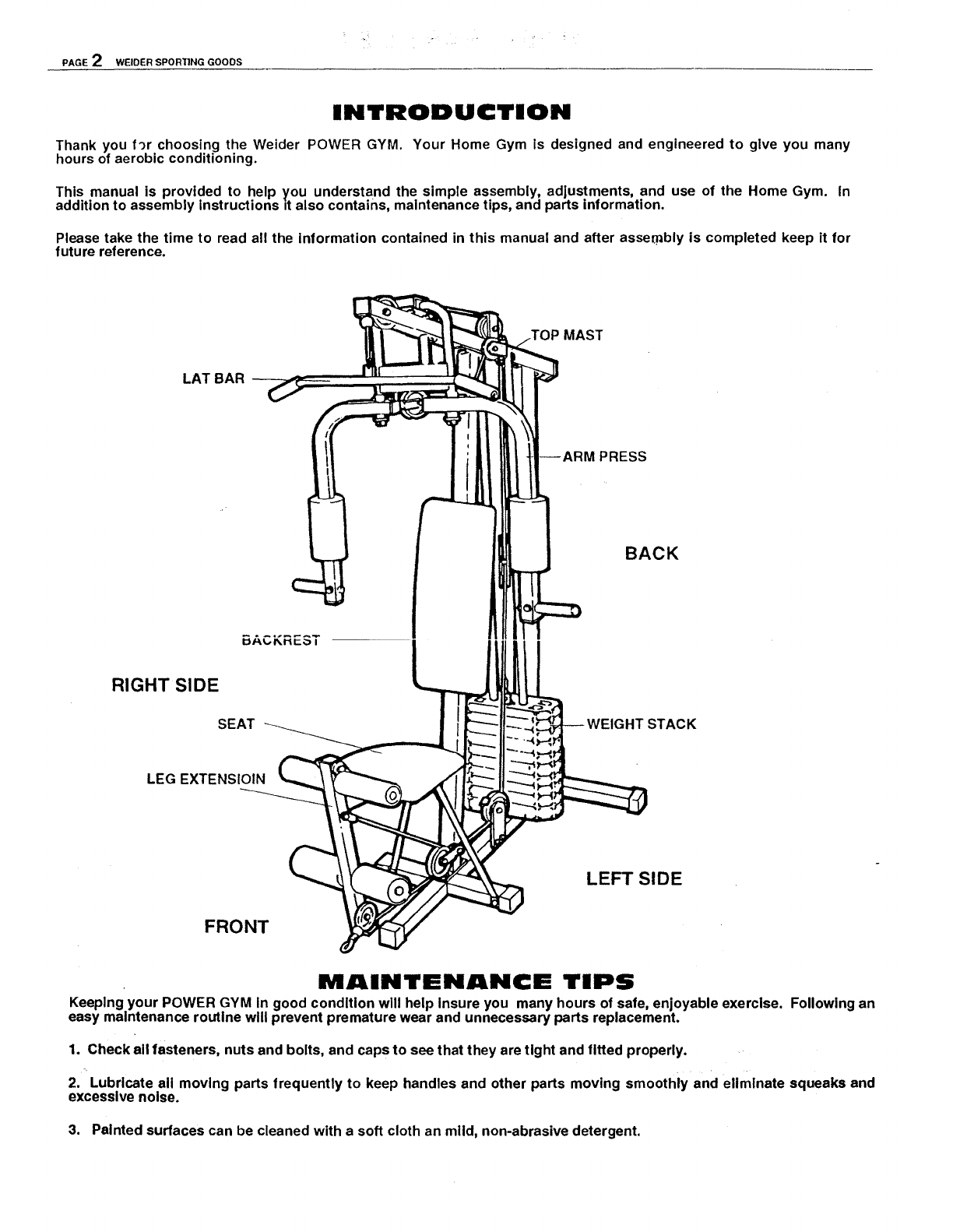
Thank you f_r choosing the Welder POWER GYM. Your Home Gym is designed and engineered to give you many
hours of aerobic conditioning.
This manual is provided to help you understand the simple assembly, adjustments, and use of the Home Gym. In
addition to assembly instructions it also contains, maintenance tips, and parts information.
Please take the time to read all the information contained in this manual and after assembly is completed keep it for
future reference.
TOP MAST
LAT BAR --
PRESS
BACK
5ACKREST
RIGHT SIDE
SEAT STACK
LEG EXTENSIOIN
LEFT SIDE
FRONT
MAINTENANCE TIPS
Keeping your POWER GYM In good condition will help Insure you many hours of safe, enjoyable exercise. Following an
easy maintenance routine will prevent premature wear and unnecessary parts replacement.
1. Check all fasteners, nuts and bolts, and caps to see that they are tight and fitted properly.
2. Lubricate all moving parts frequently to keep handles and other parts moving smoothly and eliminate squeaks and
excessive noise.
3. Painted surfaces can be cleaned with a soft cloth an mild, non-abrasive detergent.
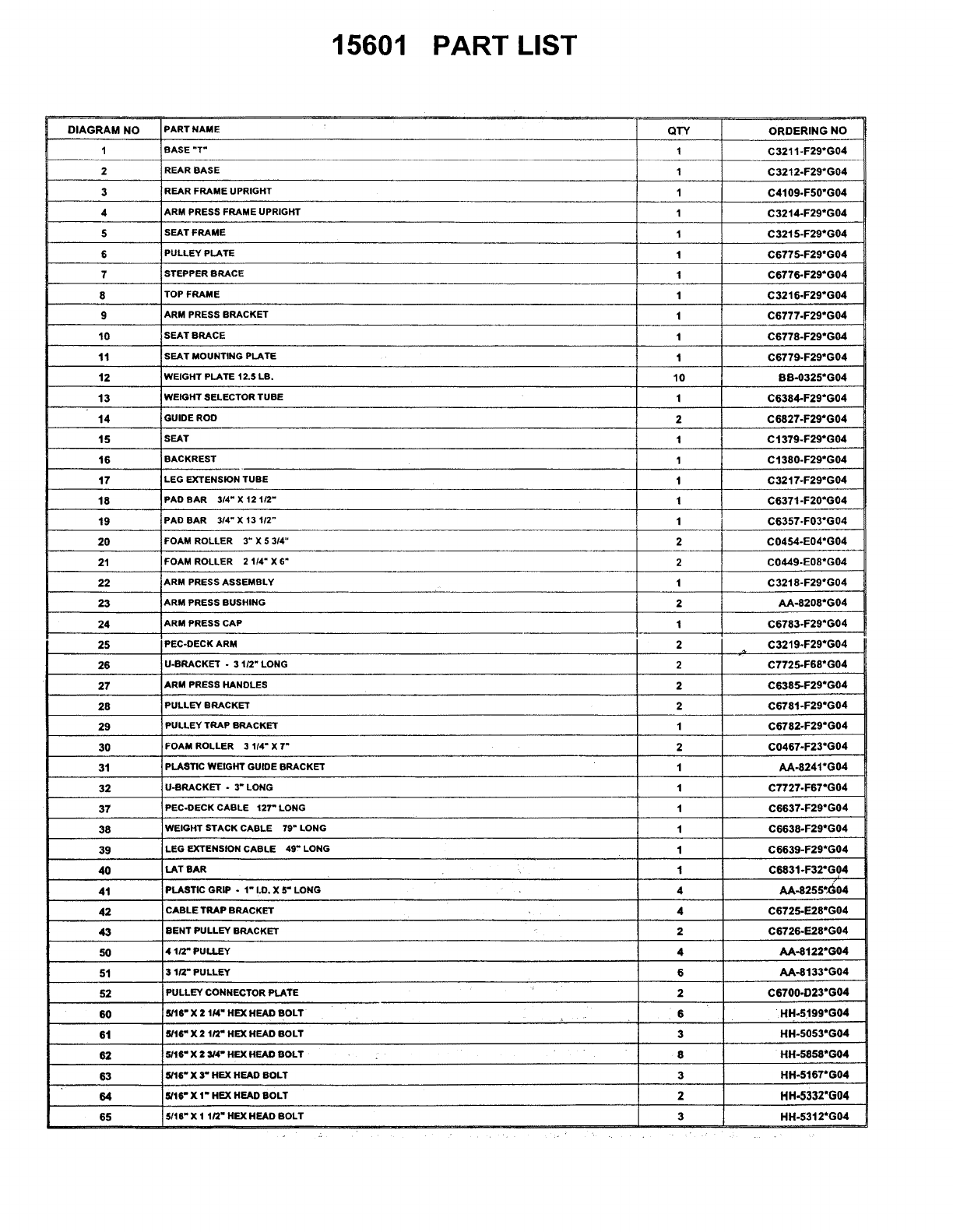
15601 PART LIST
DIAGRAM NO
1
2
3
4
5
6
7
8
9
10
11
12
13
14
15
16
17
18
19
20
21
22
23
24
25
26
27
28
29
3O
31
32
37
38
39
4O
41
42
43
50
51
52
60
61
62
63
64
65
PART NAME
BASE "T"
REAR BASE
REAR FRAME UPRIGHT
ARM PRESS FRAME UPRIGHT
SEAT FRAME
PULLEY PLATE
STEPPER BRACE
TOP FRAME
ARM PRESS BRACKET
SEAT BRACE
SEAT MOUNTING PLATE
WEIGHT PLATE 12.5 LB.
WEIGHT SELECTOR TUBE
GUIDE ROD
SEAT
BACKREST
LEG EXTENSION TUBE
PAD BAR 3/4" X 12 1/2"
PAD BAR 3/4" X 13 1/2"
FOAM ROLLER 3" X 53/4"
FOAM ROLLER 2 1/4" X 6"
ARM PRESS ASSEMBLY
ARM PRESS BUSHING
ARM PRESS CAP
IPEC-OECK ARM
U-BRACKET - 3 1/2" LONG
ARM PRESS HANDLES
PULLEY BRACKET
PULLEY TRAP BRACKET
FOAM ROLLER 3 1/4" X 7"
PLASTIC WEIGHT GUIDE BRACKET
U-BRACKET - 3" LONG
PEC-OECK CABLE 127" LONG
WEIGHT STACK CABLE 79" LONG
LEG EXTENSION CABLE 49" LONG
LAT BAR
PLASTIC GRIP -1" 1,0. X 5" LONG
CABLE TRAP BRACKET
BENT PULLEY BRACKET
4 1/2" PULLEY
3 1/2" PULLEY
PULLEY CONNECTOR PLATE
5116 =X 2 1/4" HE)( HEAD BOLT
5/16 = X 2 1/2 = HE)( HEAD BOLT
5/16 _X 2 3/4" HEX HEAD BOLT
5/16" X 3" HEX HEAD BOLT
5/16" X 1" HEX HEAD BOLT
5/t6" X 1 1/2" HEX HEAD BOLT
÷
QTY
1
1
1
1
1
1
1
1
1
1
1
10
1
2
1
1
1
1
1
2
2
1
2
1
2
2
2
2
1
2
1
1
1
1
1
1
4
4
2
4
6
2
ORDERING NO
C3211-F29*G04
C3212-F29*G04
C4109-F50*G04
C3214-F29*G04
C3215-F29*G04
C6775-F29*G04
C6776-F29*G04
C3216-F29*G04
C6777-F29*G04
C6778-F29*G04
C6779-F29*G04
BB-0325*G04
C6384-F29*G04
C6827-F29*G04
C t379-F29*G04
C1380-F29*G04
C3217-F29*G04
C6371-F20*G04
C6357-F03*G04
C0454-E04*G04
C0449-E08*G04
C3218-F29*G04
AA-8208*G04
C6783-F29*G04
C3219-F29*G04
C7725-F68*G04
C6385-F29*G04
C6781 -F29*G04
C6782-F29*G04
C0467-F23*G04
AA-8241*G04
C7727-F67*G04
C6637-F29*G04
C6638-F29*G04
C6639-F29*G04
C6831 -F32*G04
AA-8255"_;04
C6725-E28*G04
C6726-E28*G04
AA-8122*G04
AA-8133*G04
C6700-D23*G04
6
3
8
3
2
3
HH-5199*G04
HH-5053*G04
HH-5858*G04
HH-5167*G04
HH-5332*G04
HH-5312*G04
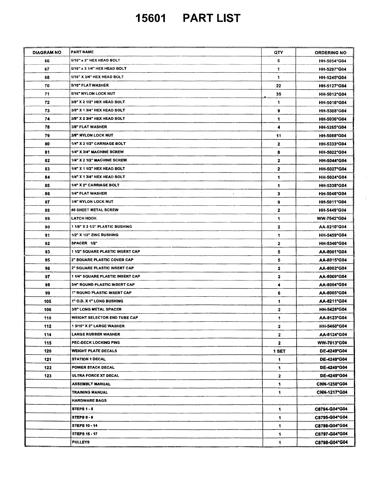
15601 PART LIST
DIAGRAM NO
66
67
68
7O
71
72
73
74
78
79
8O
81
82
83
84
85
•86
87
88
89
90
91
92
93
95
96
97
98
99
105
106
110
112
114
115
120
121
122
123
PART NAME
5/16" x 2" HEX HEAD BOLT
5/16" x 3 1/4" HEX HEAD BOLT
5116" X 3/4" HEX HEAD BOLT
5116" FLAT WASHER
5116" NYLON LOCK NUT
3/8" X 2 112" HEX HEAD BOLT
3/8" X 1 3/4" HEX HEAD BOLT
3/8" X 2 3/4" HEX HEAD BOLT
3/8" FLAT WASHER
3/8" NYLON LOCK NUT
1/4" X 2 t/2" CARRIAGE BOLT
1/4" X 314" MACHINE SCREW
1/4" X 2 1/2" MACHINE SCREW
114" X 1 1/2 _HEX HEAD BOLT
114" X 1 3/4" HEX HEAD BOLT
1/4" X 2" CARRIAGE BOLT .
114" FLAT WASHER
I/4" NYLON LOCK NUT
#8 SHEET METAL SCREW
LATCH HOOK
1 118" X 2 1/2" PLASTIC BUSHING
112" X 112" ZINC BUSHING
SPACER 1/2"
1 1/2" SQUARE PLASTIC INSERT CAP
2" SQUARE PLASTIC COVER CAP
2" SQUARE PLASTIC INSERT CAP
1 1!4" SQUARE PLASTIC INSERT CAP
314" ROUND PLASTIC INSERT CAP
1" ROUND PLASTIC INSERT CAP
t" O.D. X 1" LONG BUSHING
3/8" LONG METAL SPACER
WEIGHT SELECTOR END TUBE CAP
1 3/16" X 2" LARGE WASHER
LARGE RUBBER WASHER
PEC-DECK LOCKING PINS
WEIGHT PLATE DECALS
STATION 1 DECAL
POWER STACK DECAL
ULTRA FORCE XT DECAL
ASSEMBLY MANUAL
TRAINING MANUAL
HARDWARE BAGS
STEPS 1 - $
STEP8 6-9
STEP8 t0 - t4
lSTEPS 15 - t7
PULLEYS
t
QTY
5
1
1
22
35
1
9
1
4
tl
2
8
2
2
t
1
3
9
2
1
2
1
2
5
5
2
2
4
6
1
2
1
2
2
2
1 SET
1
t
2
1
1
1
1
1
1
1
ORDERING NO
HH-5054*G04
HH-5297*G04
HH-5245*G04
HH-5127*G04
HH-5012*G04
HH-5018*G04
HH-5308*G04
HH-5036*G04
HH-5265*G04
HH-5088*G04
HH-5333*G04
HH-5022*G04
HH-5044*G04
HH-5027*G04
HH-5024*G04
HH-5338*G04
HH-5048*G04
HH-5011*G04
HH-5449*G04
WW.7042*G04
AA-8210*G04
HH-5459*G04
HH.5346*G04
AA-8001*G04
AA-8015°G04
AA-8002°G04
AA-8069*G04
AA-8004*G04
AA-8005*G04
AA-8211*G04
HH-5428*G04
AA-8123*G04
HH-5460*G04
AA-8124*G04
WW-7013*G04
DE-4249*G04
DE-4249*G04
DE-4249*G04
DE-4249*G04
CNN-t258*G04
CNN-t217*G04
C8794-G04*G04
C8795-G04*G04
C8796-G04*G04
C8797-G04*G04
C8798-G04*G04
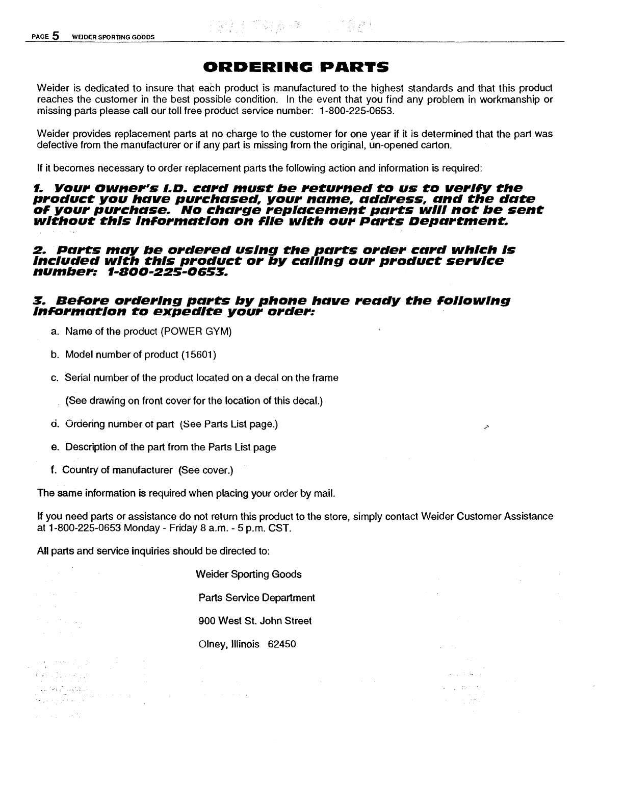
PAGE 5 WFJDER SPORTING GOODS
ORDERING PARTS
Welder is dedicated to insure that each product is manufactured to the highest standards and that this product
reaches the customer in the best possible condition. In the event that you find any problem in workmanship or
missing parts please call our toll free product service number: 1-800-225-0653.
Weider provides replacement parts at no charge to the customer for one year if it is determined that the part was
defective from the manufacturer or if any part is missing from the original, un-opened carton.
If it becomes necessary to order replacement parts the following action and information is required:
1. Your Owner's LD. card must be returned to us to verify the
product you have purchased, your name, address, and the date
of your purchase. No charge replacement parts will not be sent
without this information on file with our Parts Department.
2. Parts may be ordered using the parts order card which Is
Included with this product or by calling our product service
number: 1-800-225-0653.
Before ordering parts by phone have ready the following
Information to expedite your order:
a. Name of the product (POWER GYM)
b. Model number of product (15601)
c. Serial number of the product located on a decal on the frame
(See drawing on front cover for the location of this decal.)
d. Ordering number of part (,See Parts List page.) _
e. Description of the part from the Parts List page
f. Country of manufacturer (See cover.)
The same information is required when placing your order by mail.
If you need parts or assistance do not return this product to the store, simply contact Weider Customer Assistance
at 1-800-225-0653 Monday - Friday 8 a.m. - 5 p.m. CST.
All parts and service inquiries should be directed to:
Welder Sporting Goods
Parts Service Department
900 West St. John Street
Olney, Illinois 62450
PAGE 6 WELDER SPORTING GOOOS '
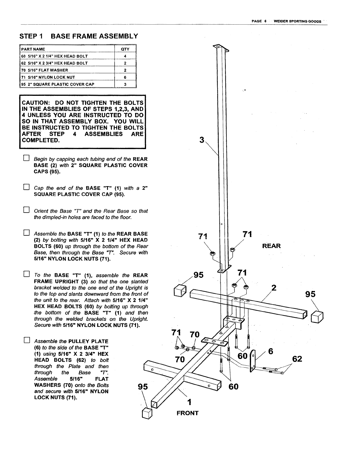
STEP 1 BASE FRAME ASSEMBLY
PART NAME QTY
60 5116" X 2 114" HEX HEAD BOLT 4
62 5/16" X 2 3/4" HEX HEAD BOLT 2
70 5/16" FLAT WASHER 2
71 5/16" NYLON LOCK NUT 6
95 2" SQUARE PLASTIC COVER CAP 3
CAUTION: DO NOT TIGHTEN THE BOLTS
IN THE ASSEMBLIES OF STEPS 1,2,3, AND
4 UNLESS YOU ARE INSTRUCTED TO DO
SO IN THAT ASSEMBLY BOX. YOU WILL
BE INSTRUCTED TO TIGHTEN THE BOLTS
AFTER STEP 4 ASSEMBLIES ARE
COMPLETED.
[] Begin by capping each tubing end of the REAR
BASE (2) with 2" SQUARE PLASTIC COVER
CAPS !95).
[] Cap the end of the BASE "T" (1) with a2"
SQUARE PLASTIC COVER CAP (95).
[] Orient the Base "T" and the Rear Base so that
the dimpled-in holes are faced to the floor.
[] Assemble the BASE "T" (1) to the REAR BASE
(2) by bolting with 5116" X 2 114" HEX HEAD
BOLTS (60) up through the bottom of the Rear
Base, then through the Base "-r". Secure with
5/16" NYLON LOCK NUTS (71).
[] To the BASE "T" (1), assemble the REAR
FRAME UPRIGHT (3) so that the one slanted
bracket welded to the one end of the Upright is
to the top and slants downward from the front of
the unit to the rear. Attach with 5116" X 2 1/4"
HEX HEAD BOLTS (60) by bolting up through
the bottom of the BASE "T" (1) and then
through the welded brackets on the UprighL
Secure with 5116" NYLON LOCK NUTS (71).
[] Assemble the PULLEY PLATE
(6) to the side of the BASE "T"
(1) using 5116" X 2 314" HEX
HEAD BOLTS (62) to bolt
through the Plate and then
through the Base "T".
Assemble 5116" FLAT
WASHERS (70) onto the Bolts
and secure with 5116" NYLON
LOCK NUTS (71).
95
71
71 70
70
1
FRONT
71
60
71
REAR
295
662
PAGE 7 WELDER SPORTING GOODS
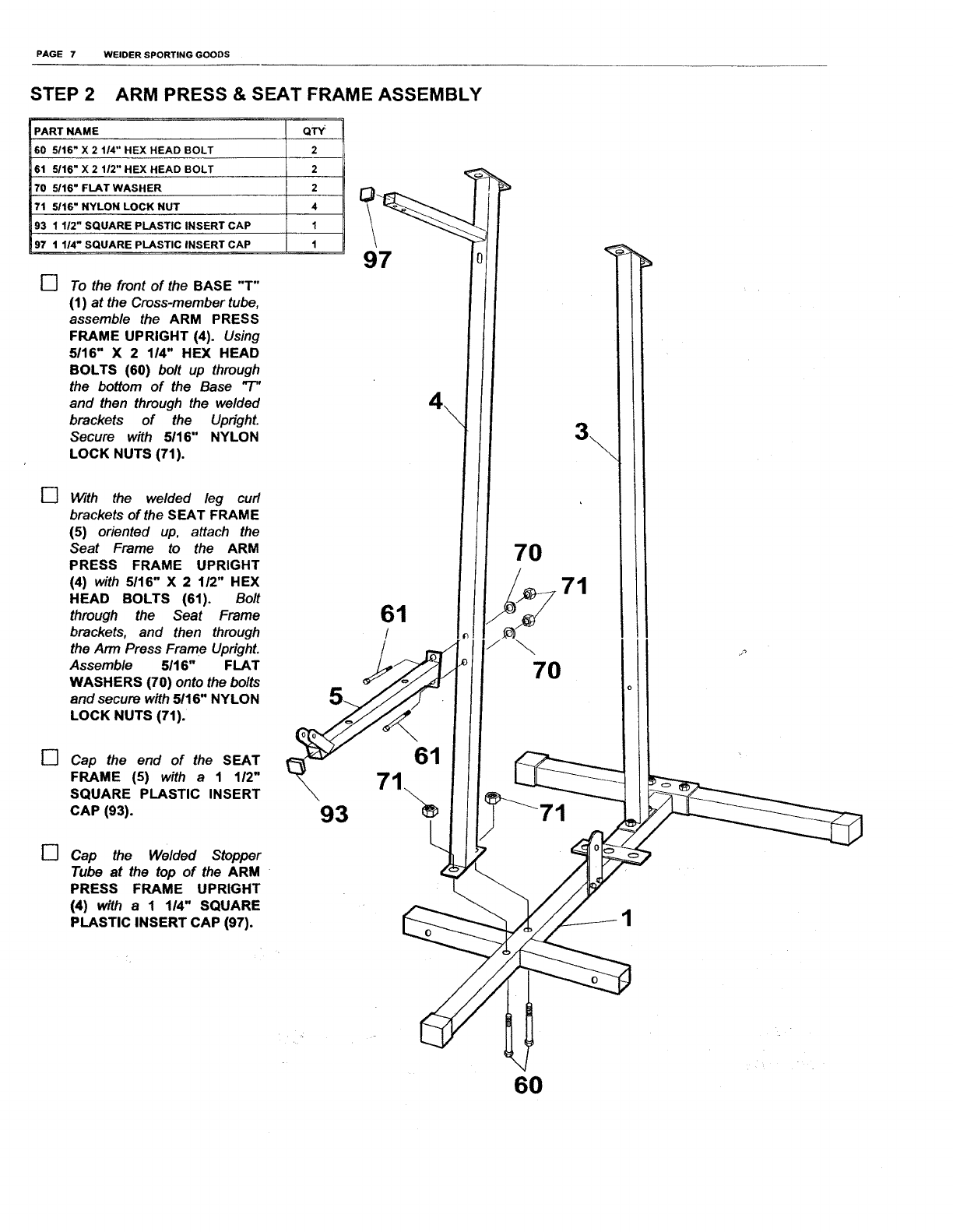
STEP 2 ARM PRESS & SEAT FRAME ASSEMBLY
PART NAME Q'W
60 5/16" X 2 1/4" HEX HEAD BOLT 2
61 5116" X 2 112" HEX HEAD BOLT 2
70 5116" FLAT WASHER 2
71 5116" NYLON LOCK NUT 4
93 1 1/2" SQUARE PLASTIC INSERT CAP 1
97 1 I14" SQUARE PLASTIC INSERT CAP 1
[] To the front of the BASE "T"
(1) at the Cross-member tube,
assemble the ARM PRESS
FRAME UPRIGHT (4). Using
5/16" X 2 1/4" HEX HEAD
BOLTS (60) bolt up through
the bottom of the Base "P'
and than through the welded
brackets of the Upright.
Secure with 5116" NYLON
LOCK NUTS (71).
[] With the welded leg curl
brackets of the SEAT FRAME
(5) oriented up, attach the
Seat Frame to the ARM
PRESS FRAME UPRIGHT
(4) with 5/16" X 2 1/2" HEX
HEAD BOLTS (61). Bolt
through the Seat Frame
brackets, and then through
the Arm Press Frame Upright.
Assemble 5116" FLAT
WASHERS (70) onto the bolts
and secure with 5116" NYLON
LOCK NUTS (71).
[] Cap the end of the SEAT
FRAME (5) with a 1 112"
SQUARE PLASTIC INSERT
CAP (93).
97
7O
61
1
71
[] Cap the Welded Stopper
Tube at the top of the ARM
PRESS FRAME UPRIGHT
(4) with a 1 114" SQUARE
PLASTIC INSERT CAP (97).
3\
6O
PAGE 8 WEIDERSPORTINGGOODS
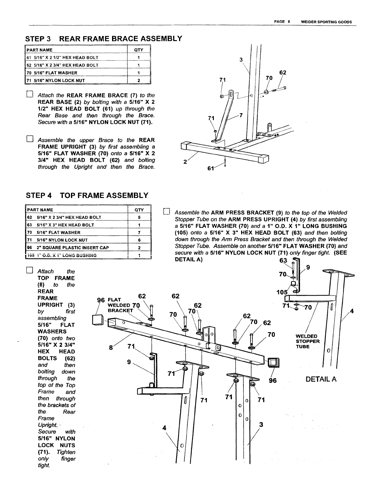
STEP 3 REAR FRAME BRACE ASSEMBLY
PART NAME QTY
61 5/16" X 2 1/2" HEX HEAD BOLT 1
62 5/16" X 2 3/4" HEX HEAD BOLT 1
70 5116" FLAT WASHER 1
71 5116" NYLON LOCK NUT 2
[] Attach the REAR FRAME BRACE (7) to the
REAR BASE (2) by bolting with a5/16" X 2
1/2" HEX HEAD BOLT (61) up through the
Rear Base and then through the Brace.
Secure with a 5116" NYLON LOCK NUT (71).
[] Assemble the upper Brace to the REAR
FRAME UPRIGHT (3) by first assembling a
5/16" FLAT WASHER (70) onto a 5116" X 2
3/4" HEX HEAD BOLT (62) and bolting
through the Upright and then the Brace.
STEP 4 TOP FRAME ASSEMBLY
PART NAME QTY
62 5116" X 2 314" HEX HEAD BOLT 5
63 5116" X 3" HEX HEAD BOLT 1
70 5116" FLAT WASHER 7
71 5116" NYLON LOCK NUT 6
............... I
96 2" SQUARE PLASTIC INSERT CAP 2
io5 i" O.D.x i" LONG BUSHING I'....
[] Attach the
TOP FRAME
(8) to the
REAR
FRAME
UPRIGHT (3)
by first
assembling
5116" FLAT
WASHERS
(70) onto two
5116" X 2 3/4"
HEX HEAD
BOLTS (62)
and then
bolting down
through the
top of the Top
Frame and
then through
the brackets of
the Rear
Frame
UprighL
Secure with
5/16" NYLON
LOCK NUTS
(71). Tighten
only finger
tighL
FLAT
WELDED 70
BRACKET
62
[] Assemble the ARM PRESS BRACKET (9) to the top of the Welded
Stopper Tube on the ARM PRESS UPRIGHT (4) by first assembling
a 5/16" FLAT WASHER (70) and a 1" O.D. X 1" LONG BUSHING
(105) onto a 5/16" X 3" HEX HEAD BOLT (63) and then bolting
down through the Arm Press Bracket and then through the Welded
Stopper Tube. Assemble on another 5116" FLAT WASHER (70) and
secure with a 5/16" NYLON LOCK NUT (71) only finger tight. (SEE
DETAIL A)
62 62
70
62
62
7O
\
WELDED
STOPPER
TUBE
.
\
71 71 71
3
96 DETAIL A
PAGE 9 WELDER SPORTING GOODS
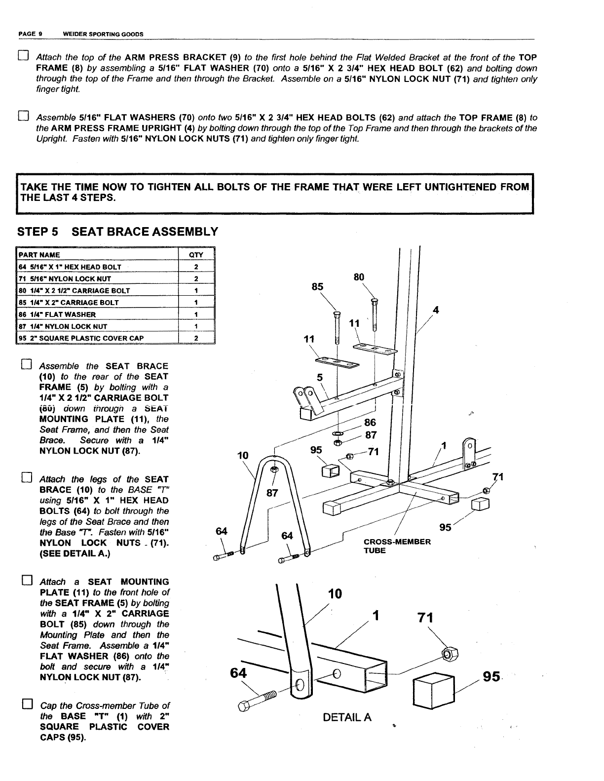
[] Attach the top of the ARM PRESS BRACKET (9) to the first hole behind the Flat Welded Bracket at the front of the TOP
FRAME (8) by assembling a 5t16" FLAT WASHER (70) onto a 5116" X2 3/4" HEX HEAD BOLT (62) and bolting down
through the top of the Frame and then through the Bracket. Assemble on a 5116" NYLON LOCK NUT (71) and tighten only
finger tight.
[] Assemble 5116" FLAT WASHERS (70) onto two 5116" X 2 314" HEX HEAD BOLTS (62) and attach the TOP FRAME (8) to
the ARM PRESS FRAME UPRIGHT (4) by bolting down through the top of the Top Frame and then through the brackets of the
Updght. Fasten with 5116" NYLON LOCK NUTS (71) and tighten only finger tighL
ITAKETHE TIME NOW TO TIGHTEN ALL BOLTS OF THE FRAME THAT WERE LEFT UNTIGHTENED FROM:]
I THE LAST 4 STEPS.
STEP 5 SEAT BRACE ASSEMBLY
PART NAME QTY
64 5/16" X 1" HEX HEAD BOLT 2
71 5/16" NYLON LOCK NUT 2
80 114" X 2 112" CARRIAGE BOLT 1
85 1/4" X 2" CARRIAGE BOLT 1
86 114" FLAT WASHER 1
87 114" NYLON LOCK NUT 1
95 2" SQUARE PLASTIC COVER CAP 2
[] Assemble the SEAT BRACE
(10) to the rear of the SEAT
FRAME (5) by bolting with a
1/4" X 2 1/2" CARRIAGE BOLT
(80) down through a_.AT
MOUNTING PLATE (11), the
Seat Frame, and then the Seat
Brace. Secure with a 114"
NYLON LOCK NUT (87).
[] Attach the legs of the SEAT
BRACE (10) to the BASE "7-"
using 5116" X 1" HEX HEAD
BOLTS (64) to bolt through the
legs of the Seat Brace and then
the Base "1". Fasten with 5/16"
NYLON LOCK NUTS _(71).
(SEE DETAIL A.)
10
\
64
80///
95 j
CROSS-MEMBER
TUBE
[]
[]
Attach a SEAT MOUNTING
PLATE (11) to the front hole of
the SEAT FRAME (5) by bolting
with a 114" X 2" CARRIAGE
BOLT (85) down through the
Mounting Plate and then the
Seat Frame. Assemble a 114"
FLAT WASHER (86) onto the
bolt and secure with a 114"
NYLON LOCK NUT (87).
Cap the Cross-member Tube of
the BASE "T" (1) with 2"
SQUARE PLASTIC COVER
CAPS (95),
1 71
6 95
DETAIL A
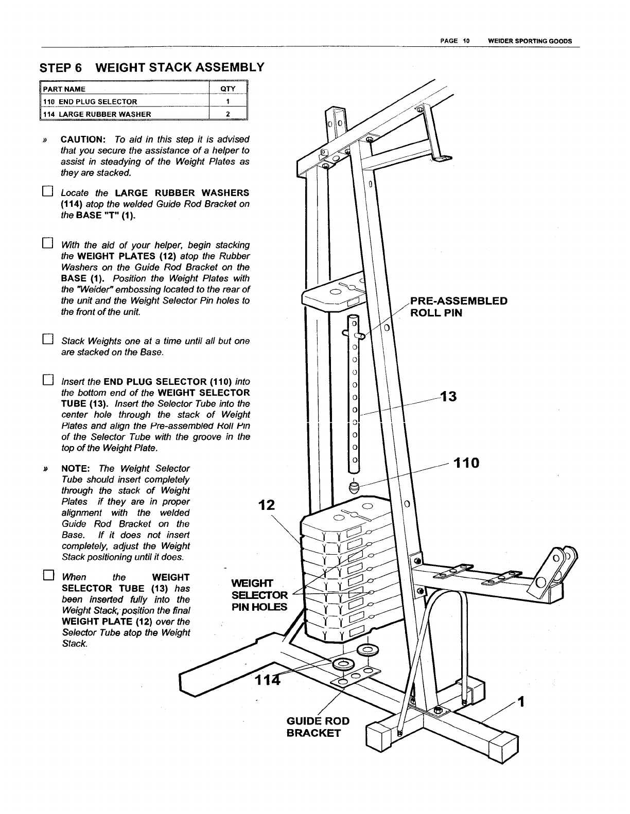
STEP 6 WEIGHT STACK ASSEMBLY
PART NAME QTY
110 END PLUG SELECTOR 1
114 LARGE RUBBER WASHER 2
[]
CAUTION: To aid in this step it is advised
that you secure the assistance of a helper to
assist in steadying of the Weight Plates as
they are stacked.
Locate the LARGE RUBBER WASHERS
(114) atop the welded Guide Rod Bracket on
the BASE "T" (1).
[] With the aid of your helper, begin stacking
the WEIGHT PLATES (12) atop the Rubber
Washers on the Guide Rod Bracket on the
BASE (1). Position the Weight Plates with
the "Weider" embossing located to the rear of
the unit and the Weight Selector Pin holes to
the front of the unit.
[] Stack Weights one at a time until all but one
are stacked on the Base.
[]
[]
Insert the END PLUG SELECTOR (110) into
the bottom end of the WEIGHT SELECTOR
TUBE (13). Insert the Selector Tube into the
center hole through the stack of Weight
Plates and align the Pre-assembled Holl Pin
of the Selector Tube with the groove in the
top of the Weight Plate.
NOTE: The Weight Selector
Tube should insert completely
through the stack of Weight
Plates if they are in proper
alignment with the welded
Guide Rod Bracket on the
Base. If it does not insert
completely, adjust the Weight
Stack positioning until it does.
12
When the WEIGHT
SELECTOR TUBE (13) has
been inserted fully into the
Weight Stack, position the final
WEIGHT PLATE (12) over the
Selector Tube atop the Weight
Stack.
WEIGHT
SELECTOR
PIN HOLES
o
PAGE 10 WELDER SPORTING GOODS
PRE-ASSEMBLED
ROLL PIN
110
GUIDE ROD
BRACKET
PAGE 11 WELDER SPORTING GOODS
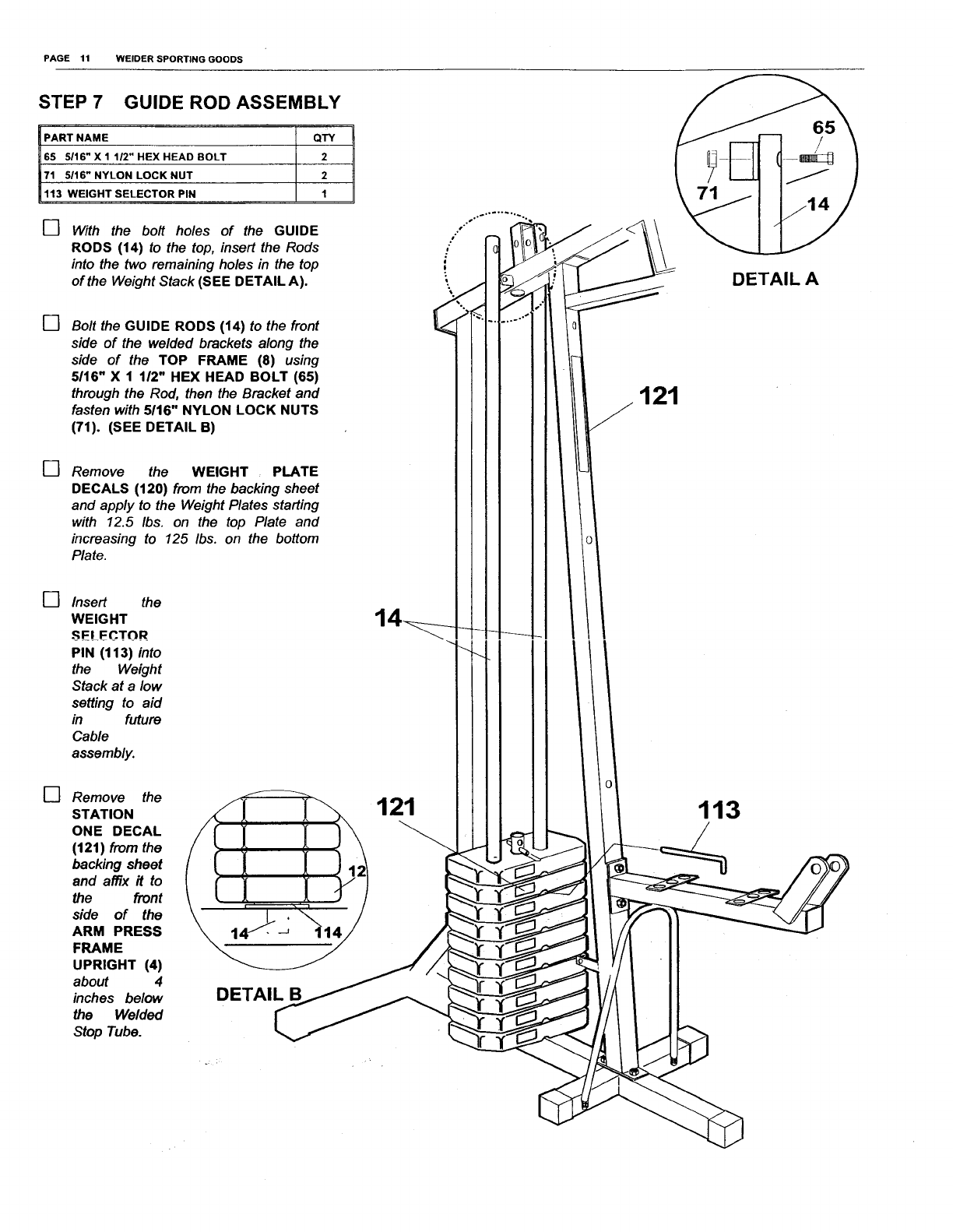
STEP 7 GUIDE ROD ASSEMBLY
PART NAME QTY
65 5/16" X 1 1/2" HEX HEAD BOLT 2
71 5/16" NYLON LOCK NUT 2
113 WEIGHT SELECTOR PIN 1
[] With the bolt holes of the GUIDE
RODS (14) to the top, insert the Rods
into the two remaining holes in the top
of the Weight Stack (SEE DETAIL A).
[] Bolt the GUIDE RODS (14) to the front
side of the welded brackets along the
side of the TOP FRAME (8) using
5116" X 1 1/2" HEX HEAD BOLT (65)
through the Rod, then the Bracket and
fasten with 5116" NYLON LOCK NUTS
(71). (SEE DETAIL B)
[] Remove the WEIGHT PLATE
DECALS (120) from the backing sheet
and apply to the Weight Plates starting
with 12.5 Ibs. on the top Plate and
increasing to 125 /bs. on the bottom
Plate.
[]
[]
Insert the
WEIGHT
SELF_.TOR
PIN (113) into
the Weight
Stack at a low
setting to aid
in future
Cable
assembly.
Remove the
STATION
ONE DECAL
(121) from the
backing sheet
and affix it to
the front
side of the
ARM PRESS
FRAME
UPRIGHT (4)
about 4
inches below
the Welded
Stop Tube.
(
DETAIL B
121
121
113
65
DETAIL A
PAGE 12 WELDER SPORTING GOODS
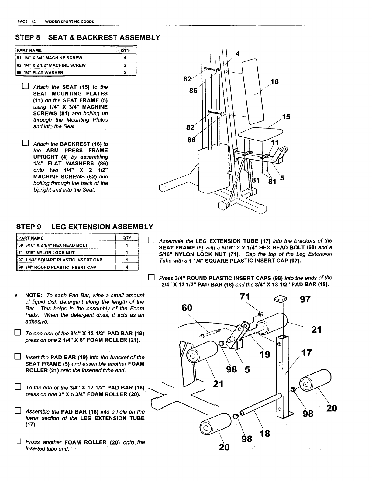
STEP 8 SEAT & BACKREST ASSEMBLY
PART NAME ' QTY
81 1/4" X 314" MACHINE SCREW 4
82 114" X 2 112" MACHINE SCREW 2
86 114" FLAT WASHER 2
[] Attach the SEAT (15) to the
SEAT MOUNTING PLATES
(11) on the SEAT FRAME (5)
using 1/4" X 3/4" MACHINE
SCREWS (81) and bolting up
through the Mounting Plates
and into the Seat.
[] Attach the BACKREST (16) to
the ARM PRESS FRAME
UPRIGHT (4) by assembling
114" FLAT WASHERS (66)
onto two 1/4" X 2 112"
MACHINE SCREWS (82) and
bolting through the back of the
Upright and into the Seal
6
11
LEG EXTENSION ASSEMBLY
60 5116" X 2 114" HEX HEAD BOLT
171 5/16" NYLON LOCK NUT I i !
97 1 114" SQUARE PLASTIC INSERT CAP
98 314" ROUND PLASTIC INSERT CAP
[]
[]
[]
[]
STEP9
[]
NOTE: To each Pad Bar, wipe a small amount
of liquid dish detergent along the length of the
Bar. This helps in the assembly of the Foam
Pads. When the detergent dries, it acts as an
adhesive.
To one end of the 314" X 13 112" PAD BAR (19)
press on one 2 1/4" X 6" FOAM ROLLER (21).
Insert the PAD BAR (19) into the bracket of the
SEAT FRAME (5) and assemble another FOAM
ROLLER (21) onto the inserted tube end.
To the end of the 314" X 12 112" PAD BAR (18)
press on one 3" X 5 3/4" FOAM ROLLER (20).
Assemble the PAD BAR (18) into a hole on the
lower section of the LEG EXTENSION TUBE
(17).
Press another FOAM ROLLER (20) onto the
inserted tube end.
Assemble the LEG EXTENSION TUBE (17) into the brackets of the
SEAT FRAME (5) with a5/16" X 2 1/4" HEX HEAD BOLT (60) and a
5/16" NYLON LOCK NUT (71). Cap the top of the Leg Extension
Tube with aI 1/4" SQUARE PLASTIC INSERT CAP (97).
[] Press 3/4" ROUND PLASTIC INSERT CAPS (98) into the ends of the
3/4" X 12 112" PAD BAR (18) andthe 314" X 13 1/2" PAD BAR (19).
71 _---97
6O
21
21
98
19
5
17
98 20
18 18
PAGE 13 WELDER SPORTING GOODS
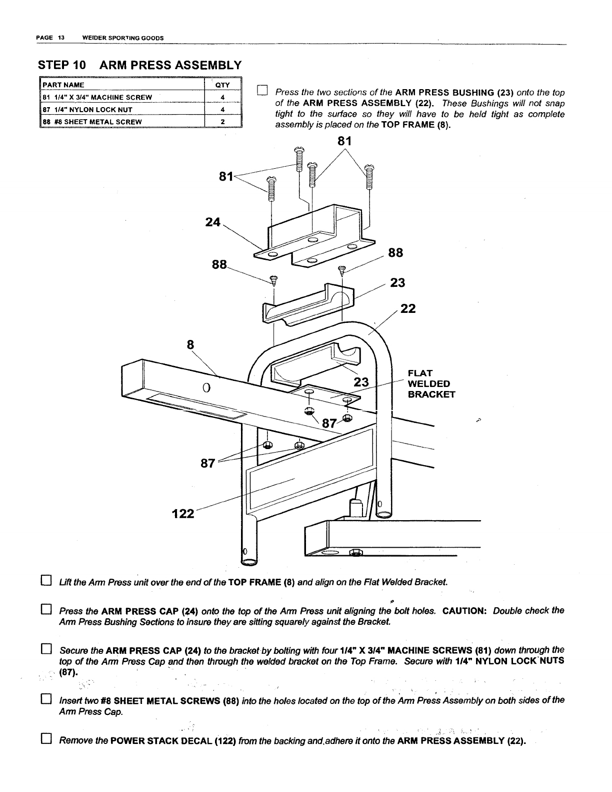
STEP 10 ARM PRESS ASSEMBLY
PART NAME QTY
81 1/4" X 3/4" MACHINE SCREW 4
87 1/4" NYLON LOCK NUT 4
88 #8 SHEET METAL SCREW 2
[] Press the two sections of the ARM PRESS BUSHING (23) onto the top
of the ARM PRESS ASSEMBLY (22). These Bushings will not snap
tight to the surface so they will have to be held tight as complete
assembly is placed on the TOP FRAME (8).
81
24
88
8
122
87
23
23
22
FLAT
WELDED
BRACKET
[]
[]
Lift the Ann Press unit over the end of the TOP FRAME (8) and align on the Flat Welded Bracket.
Press the ARM PRESS CAP (24) onto the top of the Ann Press unit aligning the bolt holes. CAUTION: Double check the
Arm Press Bushing Sections to insure they are sitting squarely against the Bracket.
[] Secure the ARM PRESS CAP (24) to the bracket.by bolting with four 114"X 314" MACHINE, SCREWS (81) down through the
top of the Ann Press Cap and then through the welded bracket on the Top Frame. Secure with 114" NYLON LOCK'NUTS
•, , (87).
[] Insert two #8 SHEET METAL SCREWS (88) into the holes located on the top of the Ann Press Assembly on both sides of the
Arm Press Cap.
[] Remove the POWER STACK DECAL (i22) from the backing and,adhere it onto the ARM PRESS ASSEMBLY (22).
PAGE 14 WELDER SPORTING GOODS
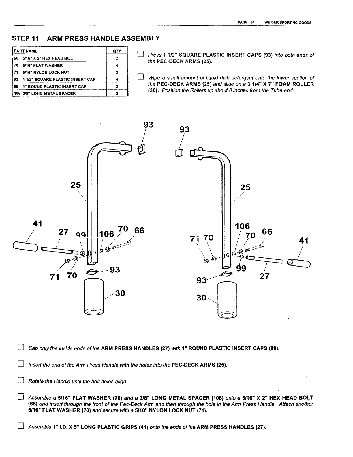
STEP 11 ARM PRESS HANDLE ASSEMBLY
RT NAME
66 5/16" X 2" HEX HEAD BOLT
70 5116" FLAT WASHER
71 5116" NYLON LOCK NUT
93 1 1/2" SQUARE PLASTIC INSERT CAP
99 1" ROUND PLASTIC INSERT CAP
106 318" LONG METAL SPACER
QTY
2
4
2
4
2
2
[]
[]
Press 1 112" SQUARE PLASTIC INSERT CAPS (93) into both ends of
the PEC-DECK ARMS (25).
Wipe a small amount of fiquid dish detergent onto the lower section of
the PEC-DECK ARMS (25) and slide on a 3 114" X 7" FOAM ROLLER
(30). Position the Rollers up about 8 inct"res from the Tube end.
93 93
41
/
25
\, \
27 99 10670
71 70 @/93
25
106
/7n 66
t*l_. ,\v 41
\
27
[]
[]
[]
[]
Cap only the inside ends of the ARM PRESS HANDLES (27) with 1" ROUND PLASTIC INSERT CAPS (99).
Insert the end of the Arm Press Handle with the holes into the PEC-DECK ARMS (25).
Rotate the Handle until the bolt holes align.
Assemble a5116" FLAT WASHER (70) and a 3/8" LONG METAL SPACER (106) onto a5116" X 2" HEX HEAD BOLT
(66) and insert through the front of the Pec-Deck Ann and then through the hole in the Arm Press Handle. Attach another
5/16" FLAT WASHER (70) and secure with a 5116" NYLON LOCK NUT (71).
[] Assemble 1" I.D. X 5" LONG PLASTIC GRIPS (41) onto the ends of the ARM PRESS HANDLES (27).
PAGE 15 WELDER SPORTING GOODS
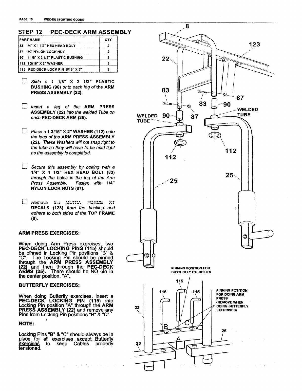
STEP 12
PART NAME
83 114" X 1 1/2" HEX HEAD BOLT
87 114" NYLON LOCK NUT
90 1 1/8" X 2 112" PLASTIC BUSHING
112 1 3116" X 2" WASHER
115 PEC-DECK LOCK PiN 5/16" X 5"
PEC-DECK ARM ASSEMBLY
QTY
2
2
2
2
2
8
[] Slide a 1 118" X 2 112" PLASTIC
BUSHING (90) onto each leg of the ARM
PRESS ASSEMBLY (22).
[] Insert aleg of the ARM PRESS
ASSEMBLY (22) into the welded Tube on
each PEC-DECK ARM (25).
[]
[]
I-3
U
Place aI 3116" X 2" WASHER (112) onto
the legs of the ARM PRESS ASSEMBLY
(22). These Washers will not snap tight to
the tube so they will have to be held tight
as the assembly is completed.
Secure this assembly by bolting with a
114" X 1 112" HEX HEAD BOLT (83)
through the holes in the leg of the Arm
Press Assembly. Fasten with 114"
NYLON LOCK NUTS (87).
n ...... ,tL. _I II "/"1'1 AI_'("lD/"_ Vl"
DECALS (123) from the backing and
adhere to both sides of the TOP FRAME
(8).
ARM PRESS EXERCISES:
When doing Arm Press exercises, two
PEC-DECK LOCKING PINS (115) should
be pinned in Locking Pin positions "B" &
"C". The Locking Pin should bepinned
through the ARM PRESS ASSEMBLY
(22)and then through the PEC-DECK
ARMS (25). There should be NO pin in
the center position, "A".
BUTTERFLY EXERCISES:
When doing Butterfly exercises, insert a
PEC-DECK LOCKING PIN (115) into
Locking Pin position "A" through the ARM
PRESS ASSEMBLY (22) and remove any
Pins from Locking Pin positions "B" & "C'.
NOTE:
Locking Pins "B" & "C" should always be in
place for all exercises except Butterflv
exercises to 'keep Cables properly
tensioned.
83
WELDED
TUBE
/
112
PINNING PosmoN FOR
BUTI'ERFLY EXERCISES
115 /
\l
115 /_/ 115 PINNINGPOSmON
II/\FOR DOING ARM
II / F'_ PRESS
.,., IF !1/ IF
PAGE 16 WEIDER SPORTING GOODS
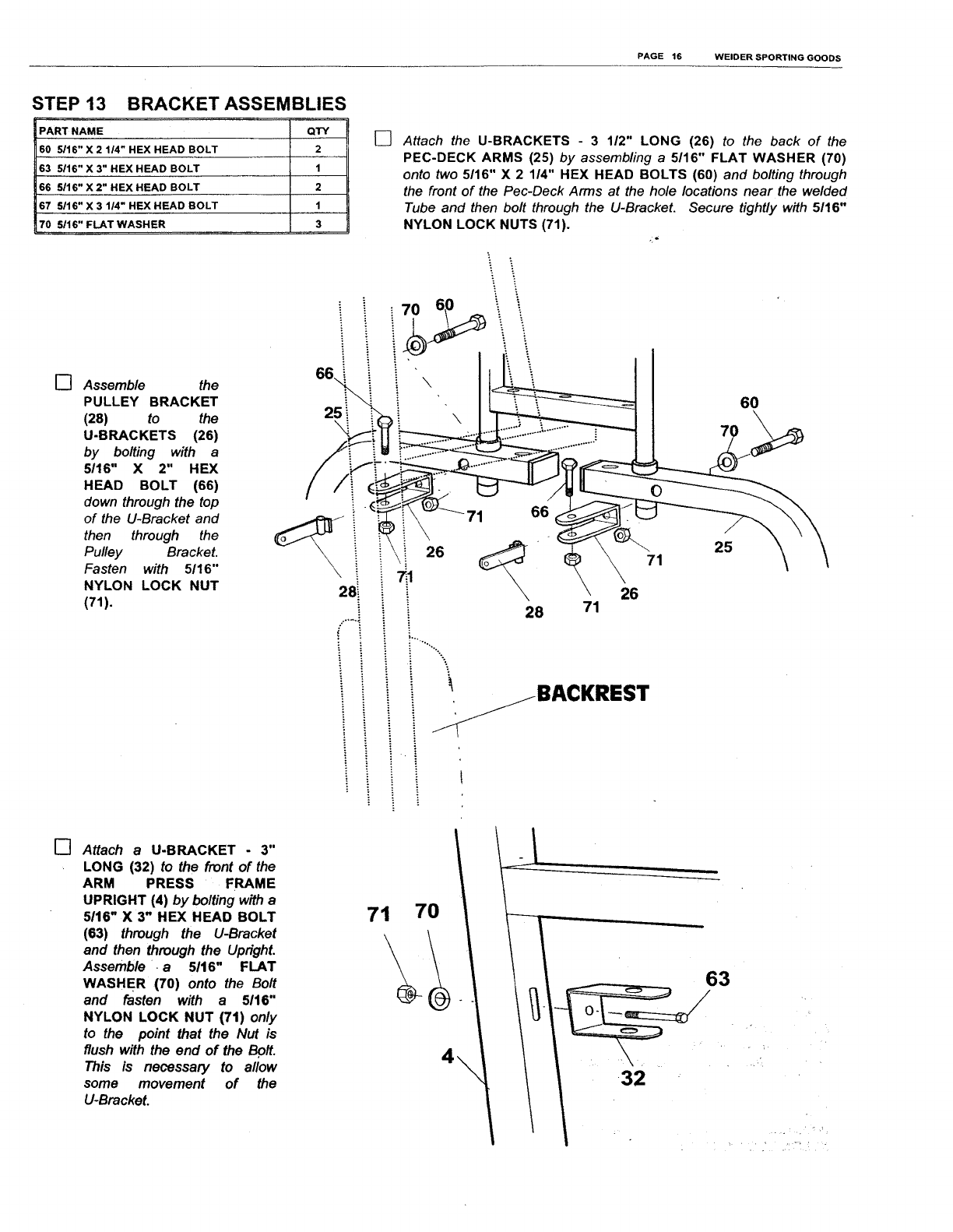
STEP 13 BRACKET ASSEMBLIES
PART NAME QTY
60 5/16" X 2 114" HEX HEAD BOLT 2
63 5116" X 3" HEX HEAD BOLT 1
66 5116" X 2" HEX HEAD BOLT 2
67 5116" X 3 114" HEX HEAD BOLT 1
70 5/16" FLAT WASHER 3
[] Assemble the
PULLEY BRACKET
(28) to the
U-BRACKETS (26)
by bolting with a
5116" X 2" HEX
HEAD BOLT (66)
down through the top
of the U-Bracket and
then through the
Pulley Bracket.
Fasten with 5116"
NYLON LOCK NUT
(71).
6° i
25i
\
[] Attach the U-BRACKETS - 3 1/2" LONG (26) to the back of the
PEC-DECK ARMS (25) by assembling a5/16" FLAT WASHER (70)
onto two 5/16" X 2 114" HEX HEAD BOLTS (60) and bolting through
the front of the Pec-Deck Arms at the hole locations near the welded
Tube and then bolt through the U-Bracket. Secure tightly with 5116"
NYLON LOCK NUTS (71).
\
!26
28i
i ..........-...
i. :
\60
28
26
71
71
BACKREST
J
[] Attach a U-BRACKET -3"
LONG (32) to the front of the
ARM PRESS FRAME
UPRIGHT (4) by bolting with a
5/16" X 3" HEX HEAD BOLT
(63) through the U-Bracket
and then through the Upright.
Assemble •a5116" FLAT
WASHER (70) onto the Bolt
and fasten with a 5/t6"
NYLON LOCK NUT (71) only
to the point that the Nut is
flush with the end of the Bo/t.
This is necessary to allow
some movement of the
U-Bracket.
63
/
/
PAGE 17 WELDER SPORTING GOODS
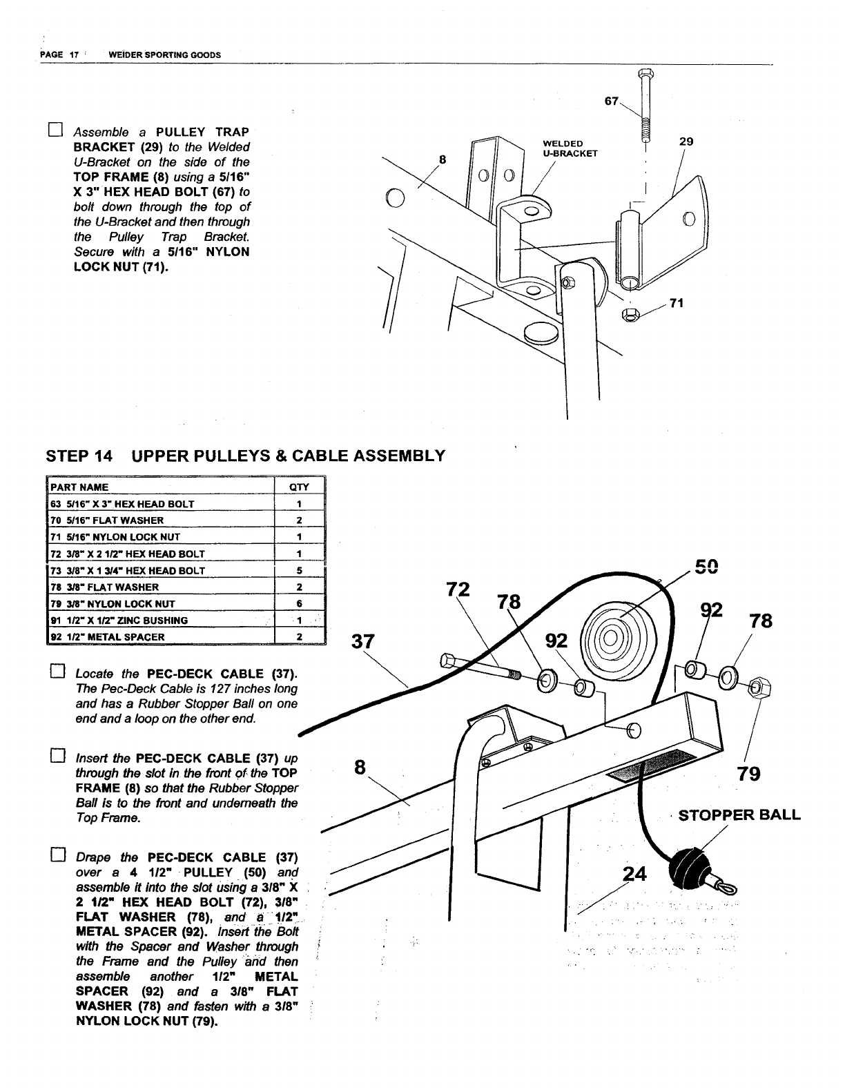
[] Assemble a PULLEY TRAP
BRACKET (29) to the Welded
U-Bracket on the side of the
TOP FRAME (8) using a 5116"
X 3" HEX HEAD BOLT (67) to
bolt down through the top of
the U-Bracket and then through
the Pulley Trap Bracket.
Secure with a 5116" NYLON
LOCK NUT (71).
©
WELDED
U-BRACKET
29
STEP 14 UPPER PULLEYS & CABLE ASSEMBLY
IPART NAME
63 5/16" X 3"HEX HEAD BOLT
70 5/16" FLAT WASHER
71 5/16" NYLON LOCK NUT
72 3/8" X 2 1/2" HEX HEAD BOLT
73 3/8" X 1 3]4" HEX HEAD BOLT
78 3]8" FLAT WASHER
79 3/8" NYLON LOCK NUT
91 1/2" X 1/2" ZINC BUSHING
92 1/2" METAL SPACER
QTY
1
2
1
1
5
2
, i
•1, ..i¸¸
2,_
[] Locate the PEC-DECK CABLE (37).
The Pec-Deck Cable is 127 inches long
and has a Rubber Stopper Bail on one
end and a loop on the other end.
37
[] Insert the PEC-DECK CABLE (37) up
through the slot in the front of the TOP
FRAME (8) so that the Rubber Stopper
Ball is to the front and underneath the
Top Frame.
8
[] Drape the PEC-DECK CABLE (37)
over a4 112" PULLEY (50) and
assemble it into the slot using a 318" X
2 t/2" HEX HEAD BOLT (72), 318"
FLAT WASHER (78), .and i_i_!12"_..
METAL SPACER (92). Insert the Bolt
with the Spacer and Washer through
the Frame and the Pulley "and then
assemble another 112" METAL
SPACER (92) and a 3/8" FLAT
WASHER (78) and fasten with a 3/8"
NYLON LOCK NUT (79).
24
_N
78
79
STOPPER BALL
/
/
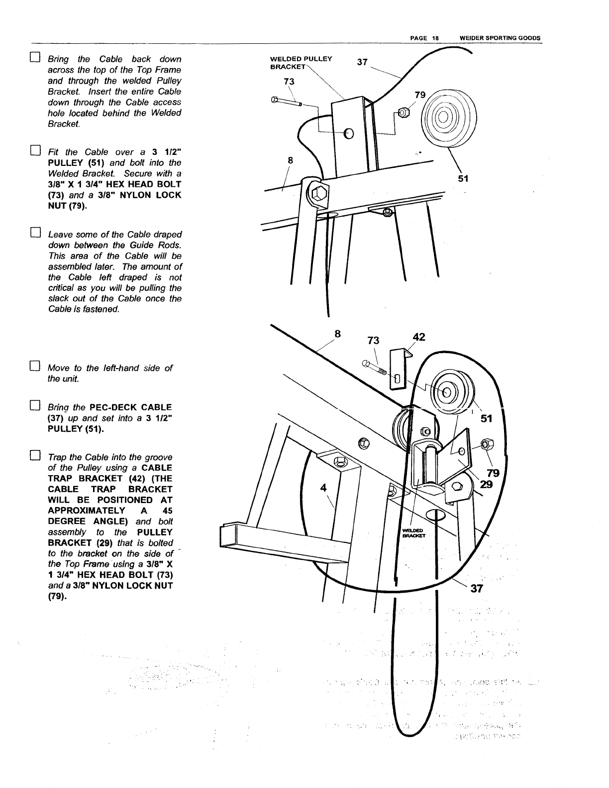
[]
[]
[]
Bring the Cable back down
across the top of the Top Frame
and through the welded Pulley
Bracket. Insert the entire Cable
down through the Cable access
hole located behind the Welded
Bracket.
Fit the Cable over a 3 112"
PULLEY (51) and bolt into the
Welded Bracket. Secure with a
3/8" X 1 314" HEX HEAD BOLT
(73) and a 318" NYLON LOCK
NUT (79).
Leave some of the Cable draped
down between the Guide Rods,
This area of the Cable will be
assembled later, The amount of
the Cable left draped is not
critical as you will be pulling the
slack out of the Cable once the
Cable is fastened.
[]
[]
[]
Move to the left-hand Side of
the unit.
Bring the PEC.DECK CABLE
(37) up and set into a3 112"
PULLEY (51).
Trap the Cable into the groove
of the Pulley using aCABLE
TRAP BRACKET (42) (THE
CABLE TRAP BRACKET
WILL BE POSITIONED AT
APPROXIMATELY A 45
DEGREE ANGLE) and bolt
assembly to the PULLEY
BRACKET (29) that is bolted
to the bracket on the side of
the Top Frame using a3/8" X
1 3/4" HEX HEAD BOLT (73)
and a3/8" NYLON LOCK NUT
(79).
._°:
PAGE 18 WELDER SPORT1NG GOODS
WELDED PULLEY 57
_7
8
51
8 73 42
I \51
37
PAGE 19 WELDER SPORTING GOODS
25
73
79
25
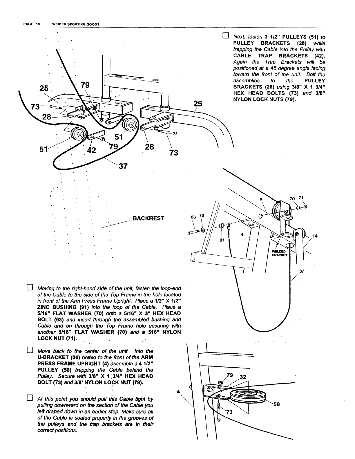
[] Next, fasten 3 112" PULLEYS (51) to
PULLEY BRACKETS (28) while
trapping the Cable into the Pulley with
CABLE TRAP BRACKETS (42).
Again the Trap Brackets will be
positioned at a 45 degree angle facing
toward the front of the unit. Bolt the
assemblies to the PULLEY
BRACKETS (28) using 318" X 1 3/4"
HEX HEAD BOLTS (73) and 3/8"
NYLON LOCK NUTS (79).
42
37
28 73
[]
[]
[]
BACKREST
FJ
Moving to the right-hand side of the unit, fasten the loop-end
of the Cable to the side of the Top Frame in the hole located
in front of the Arm Press Frame Upright. Place a 112" X 112"
ZINC BUSHING (9t) into the loop of the Cable. Place a
5116" FLAT WASHER (70) onto a5116" X 3" HEX HEAD
BOLT (63) and insert through the assembled bushing and
Cable and on through the Top Frame hole secudng with
another 5/t6" FLAT WASHER (70) and a 516" NYLON
LOCK NUT (71). .,
Move back to the center of the unit. Into the
U-BRACKET (26) bolted to the front of the ARM
PRESS FRAME UPRIGHT (4) assemble a 4 1/2"
PULLEY (50) trapping the Cable behind the
Pulley. Secure with 318" X 1'314" HEX HEAD
BOLT (73) and 3/8' NYLON LOCK NUT (79).
5
At this point you should pull this Cable tight by
pulling downward on the section of the Cable you
left draped down in an earlier step. Make sure all
of the Cable is seated properly in the grooves of
the pulleys and the trap brackets are in their
correct positions.
63 7O
91
4
71
14
37
PAGE 20 WELDER SPORTING GOODS
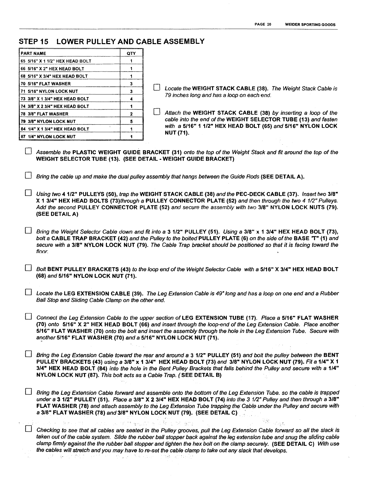
STEP 15 LOWER PULLEY AND CABLE ASSEMBLY
PART NAME
65 5/16" X 1 1/2" HEX HEAD BOLT
66 5/16" X 2" HEX HEAD BOLT
68 5/16" X 3/4" HEX HEAD BOLT
70 5116" FLAT WASHER
71 5/16" NYLON LOCK NUT
73 3/8" X 1 3/4" HEX HEAD BOLT
74 318" X 2 314" HEX HEAD BOLT
78 3/8" FLAT WASHER
79 318" NYLON LOCK NUT
84 1/4" X 1 3/4" HEX HEAD BOLT
87 1/4" NYLON LOCK NUT
QTY
I
1
1
3
3
4
1
2
5
I
I
[]
[]
Locate the WEIGHT STACK CABLE (38). The Weight Stack Cable is
79 inches long and has aloop on each end.
Attach the WEIGHT STACK CABLE (38) by inserting a loop of the
cable into the end of the WEIGHT SELECTORTUBE (13) and fasten
with a 5116" 1 112" HEX HEAD BOLT (65) and 5116" NYLON LOCK
NUT (71).
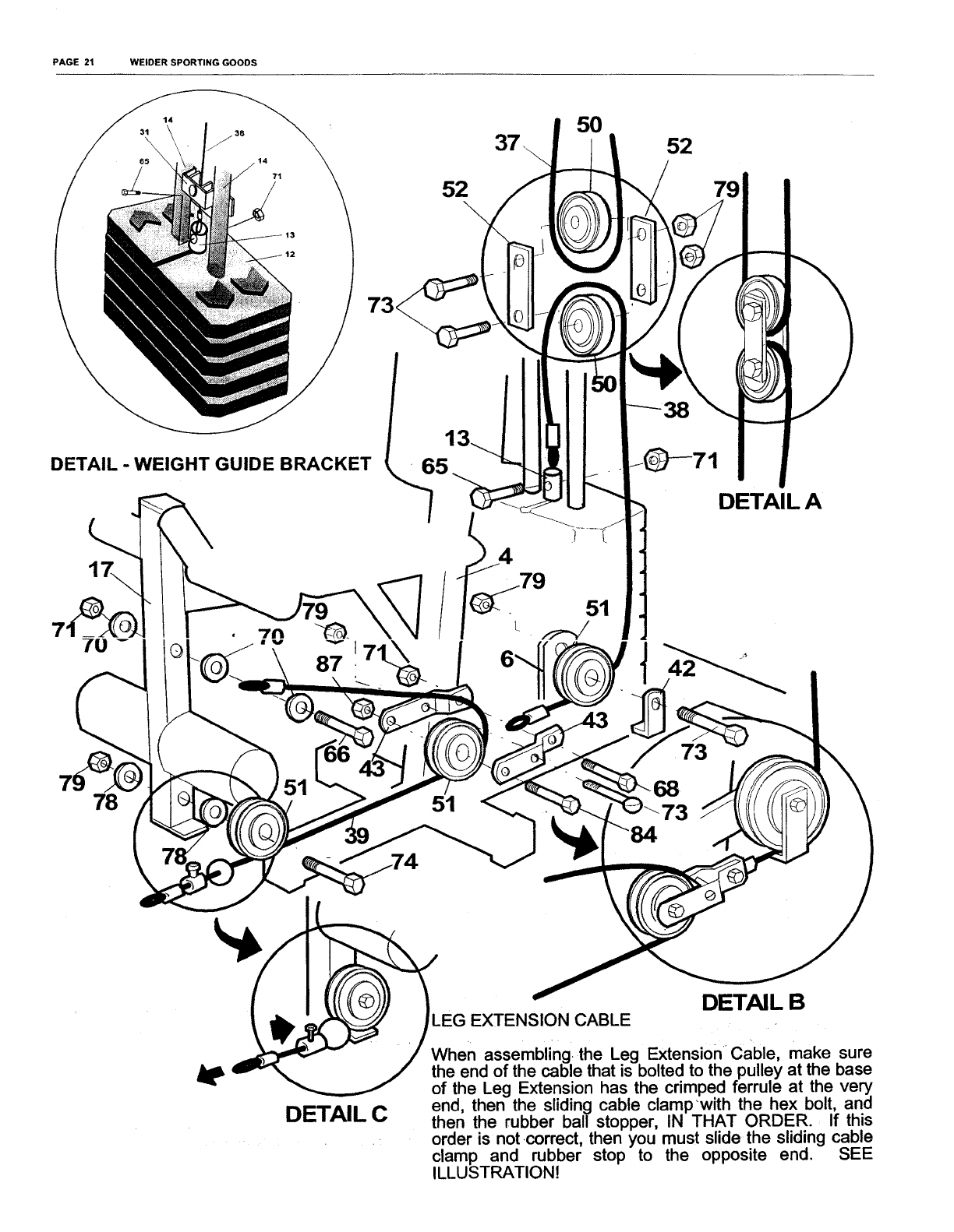
[] Assemble the PLASTIC WEIGHT GUIDE BRACKET (31) onto the top of the Weight Stack and fit around the top of the
WEIGHT SELECTOR TUBE (13). (SEE DETAIL -WEIGHT GUIDE BRACKET)
[] Bring the cable up and make the dual pulley assembly that hangs between the Guide Rods (SEE DETAIL A).
[] Using two 4 112" PULLEYS (50), trap the WEIGHT STACK CABLE (38) and the PEC-DECK CABLE (37). Insert two 318"
X 1 314" HEX HEAD BOLTS (73)through aPULLEY CONNECTOR PLATE (52) and then through the two 4 1/2" Pulleys.
Add the second PULLEY CONNECTOR PLATE (52) and secure the assembly with two 318" NYLON LOCK NUTS (79).
(SEE DETAIL A)
[] Bring the Weight Selector Cable down and fit into a 3 112" PULLEY (51). Using a 3/8" x 1 3/4" HEX HEAD BOLT (73),
bolt a CABLE TRAP BRACKET (42) and the Pulley to the bolted PULLEY PLATE (6) on the side of the BASE "T" (1) and
secure with a 318" NYLON LOCK NUT (79). The Cable Trap bracket should be positioned so that it is facing toward the
flaor_
[]
[]
[]
[]
[]
[]
Bolt BENT PULLEY BRACKETS (43) to the loop end of the Weight Selector Cable with a 5116" X 3/4" HEX HEAD BOLT
(68) and 5/16" NYLON LOCK NUT (71).
Locate the LEG EXTENSION CABLE (39). The Leg Extension Cable is 49"long and has aloop on one end and a Rubber
Bali Stop and Sliding Cable Clamp on the other end.
Connect the Leg Extension Cable to the upper section of LEG EXTENSION TUBE (17). Place a 5116" FLAT WASHER
(70) onto 5116" X 2" HEX HEAD BOLT (66) and insert through the loop-end of the Leg Extension Cable. Place another
5116" FLAT WASHER (70) onto the bolt and insert the assembly through the hole in the Leg Extension Tube. Secure with
another 5/16" FLAT WASHER (70) and a 5/16" NYLON LOCK NUT (71).
Bring the Leg Extension Cable toward the rear and around a 3 1/2" PULLEY (51) and bolt the pulley between the BENT
PULLEY BRACKETS (43) using a 318" x 1 3/4" HEX HEAD BOLT (73) and 318" NYLON LOCK NUT (79). Fit a 1/4" X 1
314" HEX HEAD BOLT (84) into the hole in the Bent Pulley Brackets that falls behind the Pulley and secure with a1/4"
NYLON LOCK NUT (87). This bolt acts as aCable Trap. (SEE DETAIL B)
Bring the Leg Extension Cable forward and assemble onto the bottom of the Leg Extension Tube. so the cable is trapped
under a 3 112" PULLEY (51). Place a 318" X 23/4" HEX HEAD BOLT (74) into the 3 1/2" Pulley and then through a 318"
FLAT WASHER (78) and attach assembly to the Leg Extension Tube trapping the Cable under the Pulley and secure with
a318" FLAT WASHER (78) and318" NYLON LOCK NUT (79). (SEE DETAIL C) _
Checking to see that all cables are seated in the Pulley grooves, pull the Leg Extension Cable forward so all the slack is
taken out of the cable system. Slide the rubber ball stopper back against the leg extension tube and snug the sliding cable
clamp firmly against the the rubber ball stopper and tighten the hex bolt on the clamp securely. (SEE DETAIL C) With use
the cables will stretch and you may have to re-set the cable clamp to take out any slack that develops.
PAGE 21 WELDER SPORTING GOODS
14
DETAIL - WEIGHT GUIDE BRACKET
7O
87
52
1:
5O
7
1
52
79
DETAIL A
•73
78 73
4e
DETAIL C
EXTENSION CABLE DETAIL B
When assembling the Leg Extension Cable, make sure
the end of the cable that is bolted to the pulley at the base
of the Leg Extension has the crimped ferrule at the very
end, then the sliding cable clampwith the hex bolt, and
then the rubber ball stopper, IN THAT ORDER. If this
order is not correct, then you must slide the sliding cable
clamp and rubber stop to the opposite end. SEE
ILLUSTRATION!
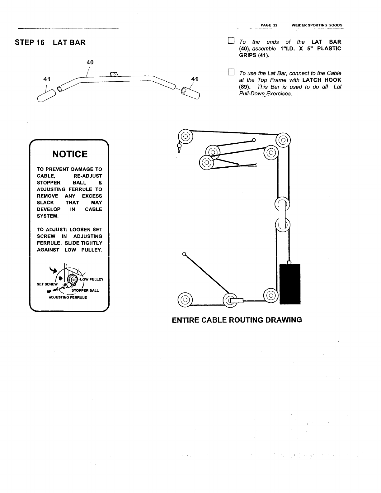
STEP 16
41
PAGE 22 WELDER SPORTING GOODS
LAT BAR []
[]
To the ends of the LAT BAR
(40), assemble 1"I.D. X 5" PLASTIC
GRIPS (41).
To use the Lat Bar, connect to the Cable
at the Top Frame with LATCH HOOK
(89). This Bar is used to do all Lat
Puff-Down Exercises.
illllllll iiillllll i i
TO PREVENT DAMAGE TO
CABLE, RE-ADJUST
STOPPER BALL &
ADJUSTING FERRULE TO
REMOVE ANY EXCESS
SLACK THAT MAY
DEVELOP IN CABLE
SYSTEM.
TO ADJUST: LOOSEN SET
SCREW IN ADJUSTING
FERRULE. SLIDE TIGHTLY
AGAINST LOW PULLEY.
_I_/_LOW PULLEY
)
ADJUSTING FERRULE
J
o.
ENTIRE CABLE ROUTING DRAWING
EXERCISE FREQUENCY
1o maintain or improve your condition, you must workout 2-3 times per week following the pattern described above. A
day of rest between workouts is recommended. After several months of exercise, the number of workouts can be
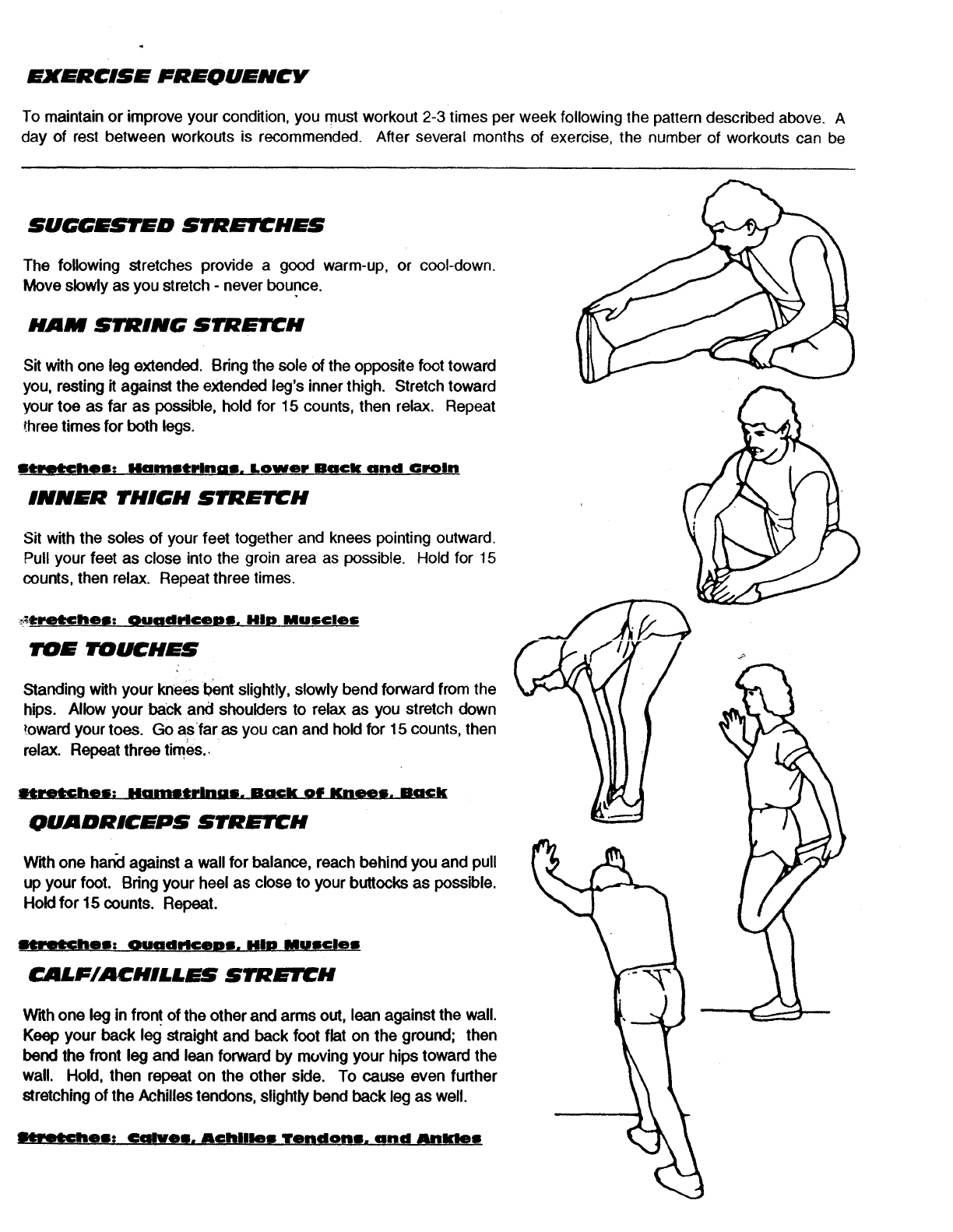
SUGGESTED STRETCHES
The following stretches provide a good warm-up, or cool-down.
Move slowly as you stretch - never bounce.
HAM STRING STRETCH
Sit with one leg extended, Bring the sole of the opposite foot toward
you, resting it against the extended leg's inner thigh. Stretch toward
your toe as far as possible, hold for 15 counts, then relax. Repeat
three times for both legs.
st_tChem: liammtring!, Lower Ba¢l( and Oroln
INNER THIGH STRETCH
Sit with the soles of your feet together and knees pointing outward.
Pull your feet as close into the groin area as possible. Hold for 15
counts, then relax. Repeat three times.
_tretChell: QuadriCeDll. HID Mull€los
TOE TOUCHES
Standing with your knees bent slightly, slowly bend forward from the
hips. Allow your back and shoulders to relax as you stretch down
toward your toes. Go asfar as you can and hold for 15 counts, then
relax. Repeat three times..
IHl:_hes: Hamotrinum. Back of Knees. Back
QUADRICEPS STRETCH
With one hanoiagainst a wall for balance, reach behind you and pull
up your foot. Bdng your heel as close to your buttocks as possible.
Hold for 15 counts. Repeat.
litroKhe|: Ouadrlcep|. HiP MU|¢le|
CALF/ACHILLES STRETCH
With one leg in front of the other and arms out, lean against the wall.
Keep your back leg straight and back foot flat on the ground; then
band the front leg and lean forward by moving your hips toward the
wall. Hold, then repeat on the other side. To cause even further
stretching of the Achilles tendons, slightly bond back leg as well.
Im_chee: Omlvem. Achilles Tendons. and Anlclem
