Weider 831159010 User Manual 2100 Manuals And Guides L0303319
WEIDER Weight System Manual L0303319 WEIDER Weight System Owner's Manual, WEIDER Weight System installation guides
User Manual: Weider 831159010 831159010 WEIDER WEIDER 2100 - Manuals and Guides View the owners manual for your WEIDER WEIDER 2100 #831159010. Home:Fitness Equipment Parts:Weider Parts:Weider WEIDER 2100 Manual
Open the PDF directly: View PDF ![]() .
.
Page Count: 26
MEIDER2100
Model No. 831.159010
Serial No.
Write the serial number in the
space above for reference.
Serial Number Decal (under seat)
_" X F-. R C I SE.
EQUIPMENT
HELPLINE!
!-800-736-6879
SEARS, ROEBUCK AND CO.
HOFFMAN ESTATES, IL 60179
USER'S MANUAL
www.weiderfit ness.com
new products, prizes,
fitness tips, and much more!
TABLE OF CONTENTS
IMPORTANT PRECAUTIONS ............................................................. 3
BEFORE YOU BEGIN ................................................................... 4
ASSEMBLY ........................................................................... 5
ADJUSTMENTS ...................................................................... 14
WEIGHT RESISTANCE CHART ........................................................... 16
CABLE DIAGRAM ..................................................................... 17
EXERCISE GUIDELINES ................................................................ 18
ORDERING REPLACEMENT PARTS ................................................ Back Cover
LIMITED WARRANTY ........................................................... Back Cover
Note:A PART IDENTIFICATION CHART and a PART LIST/EXPLODED DRAWING are attached in the center of
this manual. Remove the PART IDENTIFICATION CHART and the PART LIST/EXPLODED DRAWING before
beginningassembly.
WELDER is a registeredtrademark of ICON Health & Fitness, Inc.
2
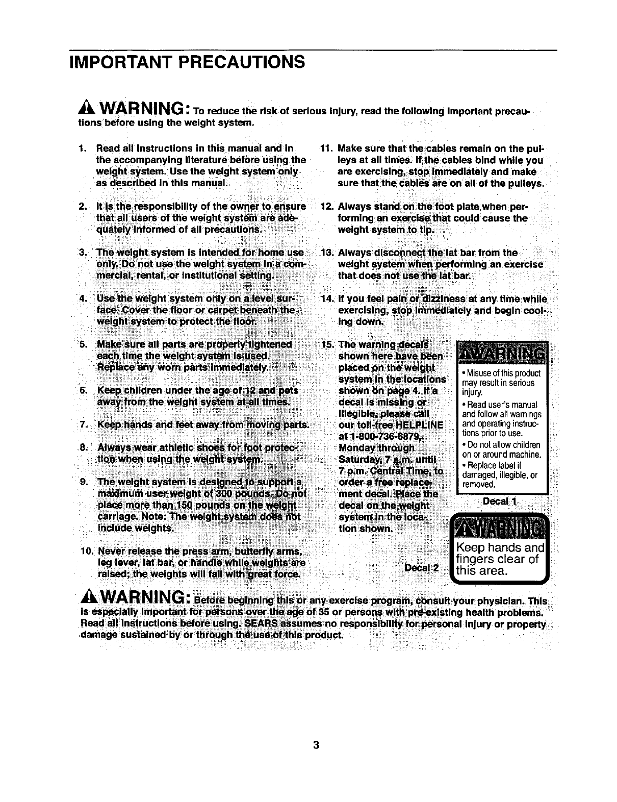
IMPORTANT PRECAUTIONS
WARNING: To reduce the rlsk of serious injury, reed the following Important precau-
tions before using the weight system.
1, Read all Instructions in this manual and In
the accompanying literature before using the
weight system. Use the weight system only
as described in this manual.
11. Make sure that the cables remain on the pul-
leys at all times. If the cables bind while you
are exercising, stop Immediately and make
sure that the cables are on all of the pulleys.
2. It Is the responsibility of the owner to ensure 12. Always stand on thefoot plate when per-
that an users of the weight system are ade- formlng an exercise that could cause the
quately Informed of all precautions, weight system to tip.
3. The weight system Is Intended forhome use 13. Always disconnect the lat bar from the
Ing down.
7. Keep hands and feet eway;frommovlngparts:
9,
our toll-free HELPLINE
Uon shown.
• Misuseofthisproduct
mayresultinserious
injury.
• Readuser'smanual
andfollowall warnings
andooeratinginstruc
tionsenortouse
• Donotallowchilaren
onorarounomacn_ne
• Replacelabelif
damaged,illegible,or
removeo.
Decal I
10. Never release the press arm, butterftyfarms,
leg lever, at bar, ()r handle whllewelgh;ts_are
raised, the weights will fall with great force. Decal 2
3
BEFORE YOU BEGIN
Thank you for selectingthe versatile WELDER®2100
weight system. The WELDER" 2100 offersaselection
of weight stations designed to develop every major
musclegroup of the body.Whether your goal is to tone
your body,build dramatic muscle size and strength, or
improveyour cardiovascular system, the WELDER®
2100 will help you to achieve the resultsyou want.
For your benefit, read this manual carefully before
using the weight system, if you have additional
questions,please call our toll-free HELPLINE at
1-800-736-6879, Monday throughSaturday,7a.m.
until7 p.m. Central Time (excludingholidays).To help
us assist you, please note the product model number
and serial number before calling.The model numberis
831.159010. The serial numbercan be found on a
decal attached to the weight system (see the front
coverof this manual).
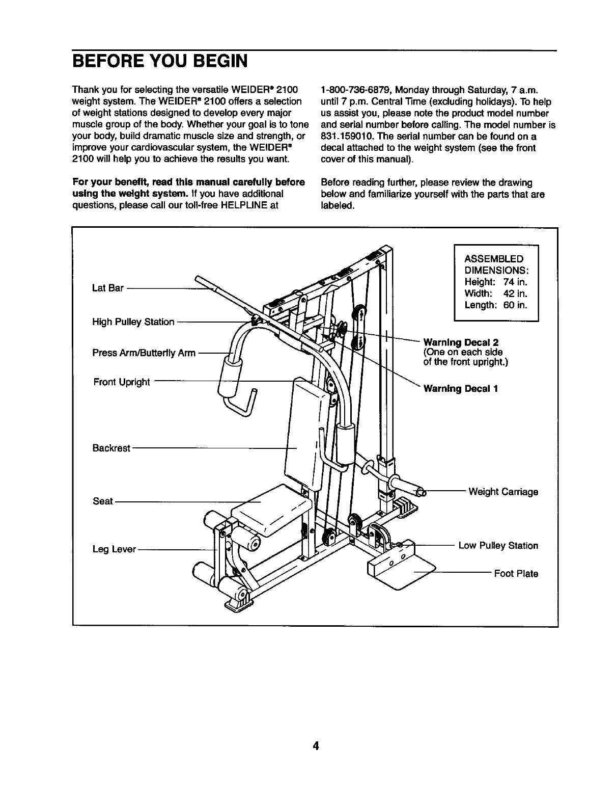
Before reading further,please review the drawing
below and familiarizeyourselfwith the parts that are
labeled.
LSt Bar
High Pulley Station
Press Arm/Butterfly
Front Upright
ASSEMBLED
DIMENSIONS:
Height: 74 in.
Width: 42 in.
Length: 60 in.
Warning Decal 2
(One on each side
of the front upright.)
Decal 1
Backrest
Seat Weight Carriage
Leg Lever Low Pulley Station
Foot Plate
4
ASSEMBLY
• As you assemble the weight system, make sure
all parts are oriented as shown in the drawings.
Before beginning assembly, carefully rend the
following Information and Instructions:
•Assembly requires two people.
•Place all parts in a cleared area and remove the
packing materials. Do not disposeof the packing
materials untilassembly is completed.
•"13ghtenall partsas you assemble them, unless
instructedto do otherwise.
•For help identifyingsmall parts, use the PART
The following tools (not Included) are required
for assembly:
•two adjustable wrenches
•one rubber mallet
•one standard screwdriver
• one Phillips screwdriver
•lubricant, such as grease or petroleum jelly,
and soapy water.
Assembly will be moreconvenient if you have a
socket set, a set of open-end or closed-end
wrenches, or a set of ratchetwrenches.
1.
2.
Before beginning assembly, be sure that you
have rend and understand the Information In
the box above.
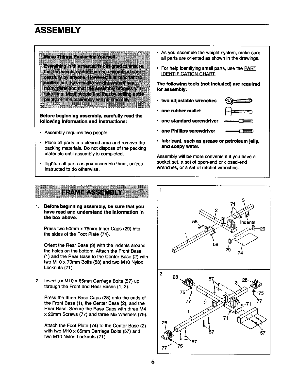
Press two 50mm x 75mm Inner Caps (29) into
the sides of the Foot Plate (74).
Orient the Rear Base (3) with the indents around
the holes on the bottom.Attach the Front Base
(1) and the Rear Base to the Center Base (2) with
two M10 x 70mm Bolts (58) and two M10 Nylon
Locknuts(71).
Insert six M10 x 65mm Carriage Bolts (57) up
throughthe Frontand Rear Bases (1, 3).
Press the three Base Caps (28) onto the ends of
the Front Base (1), the Center Base (2), and the
Rear Base. Secure the Base Caps withthree M4
x 20mm Screws (77) and three M5 Washers (75).
Attachthe Foot Plate (74) to the Center Base (2)
withtwo M10 x 65mm Carriage Bolts (57) and
two M10 Nylon Locknuts(71).
2
28
75
3
71
2
58 Indents
1
58 29 74
77
1
2
71
_75
77
-71
57 57
5
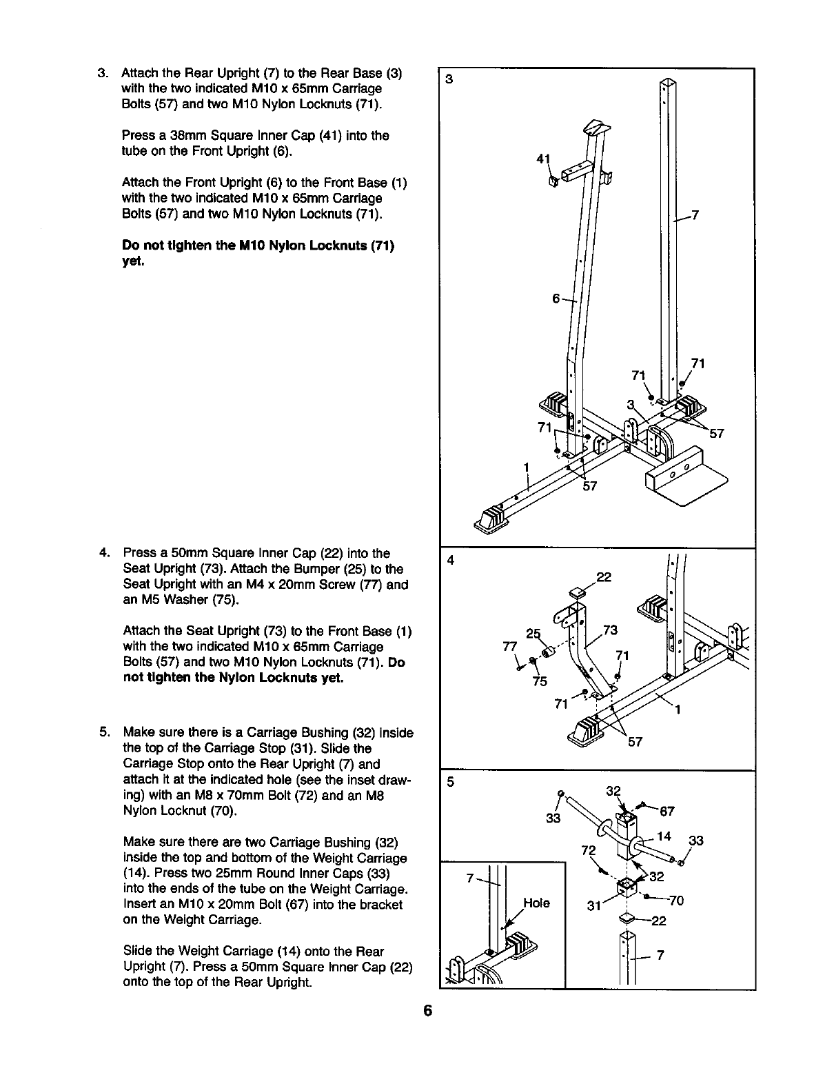
3. Attach the Rear Upright (7) to the Rear Base (3)
with the two indicated M10 x 65mm Carriage
Bolts (57) and two M10 Nylon Locknuts(71).
Press a 38mm Square InnerCap (41) intothe
tube on the Front Upright (6).
Attachthe Front Upright (6) to the FrontBase (1)
with the two indicated M10 x 65mm Carriage
Bolts (57) and two M10 Nylon Locknuts(71).
Do not tighten the MIO Nylon Locknuts (71)
yet.
4. Press a50mm Square Inner Cap (22) intothe
Seat Upright (73). Attachthe Bumper (25) to the
Seat Uprightwith an M4 x 20mm Screw (77) and
an M5 Washer (75).
Attachthe Seat Upright(73) to the Front Base (1)
with the two indicated M10 x 65mm Carriage
Bolts (57) and two M10 Nylon Locknuts(71). Do
not tighten the Nylon Locknute yet.
5. Make sure there is a Carriage Bushing(32) inside
the top of the Carriage Stop (31). Slide the
Carriage Stop onto the Rear Upright(7) and
attach it at the indicated hole (see the insetdraw-
ing) withan M8 x 70mm Bolt (72) and an M8
Nylon Locknut (70).
Make sure there are two Carriage Bushing(32)
inside the top and bottomof the Weight Carriage
(14). Press two 25mm Round Inner Caps (33)
into the ends of the tube on the Weight Carriage.
Insertan M10 x 20mm Bolt (67) intothe bracket
on the Weight Carriage.
Slide the Weight Carriage (14) onto the Rear
Upright (7). Press a 50mm Square Inner Cap (22)
onto the top of the Rear Upright.
4
77
5
6
71
1
57
22
75
57
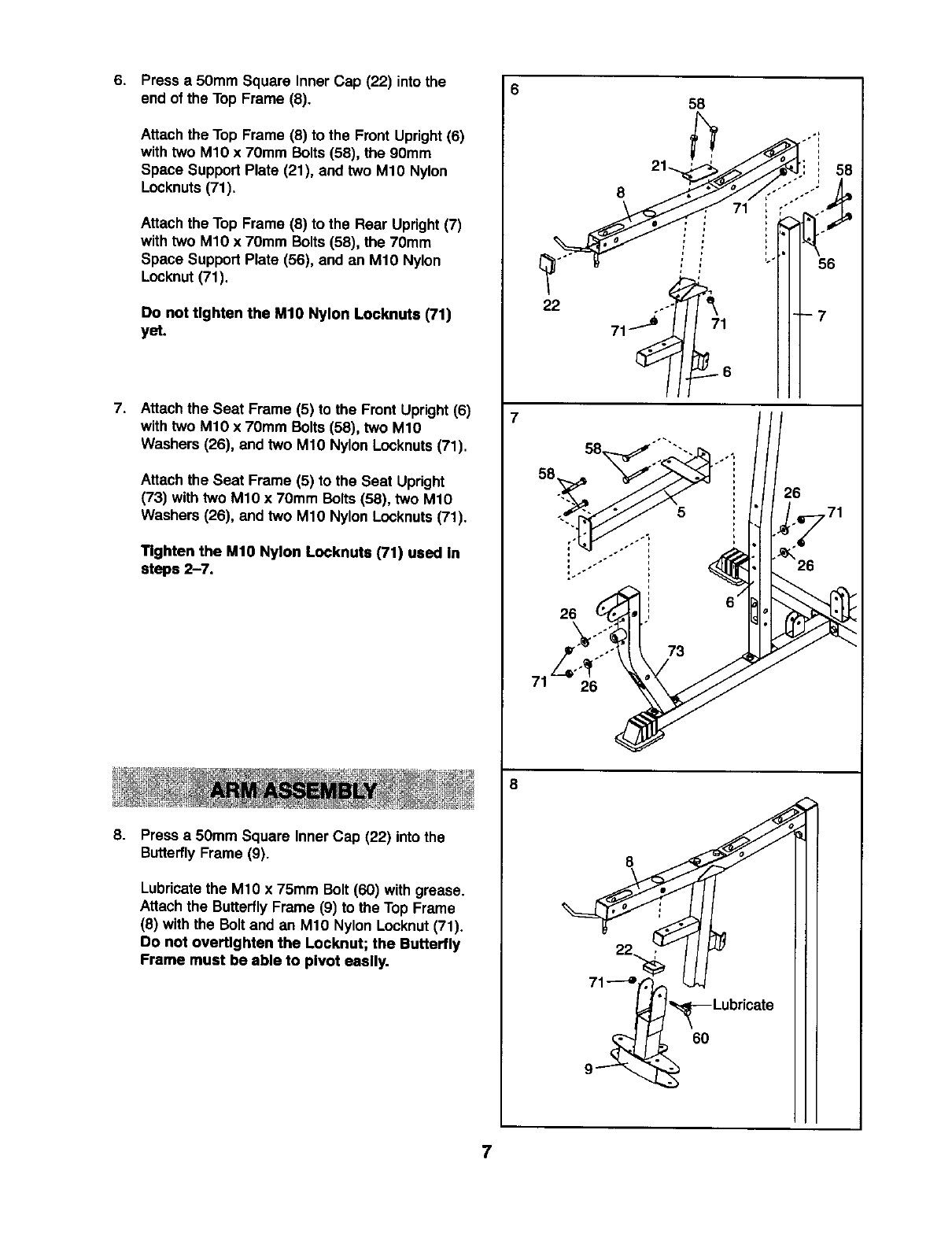
6. Press a 50mm Square Inner Cap (22) into the
end of the Top Frame (8).
Attachthe Top Frame (8) to the Front Upright(6)
withtwo M10 x 70mm Bolts (58), the 90mm
Space Support Plate (21), and two M10 Nylon
Locknuts(71).
Attach the Top Frame (8) to the Rear Upright(7)
with two M1O x 70mm Bolts(58), the 70mm
Space Support Plate (56), and an M10 Nylon
Locknut(71).
0o not tighten the M10 Nylon Looknuts (71)
yet.
7. Attachthe Seat Frame (5) to the Front Upright(6)
withtwo M10 x 70ram Bolts (58), two M10
Washers (26), and two M10 Nylon Locknuts(71).
Attach the Seat Frame (5) to the Seat Upright
(73) with two M10 x 70ram Bolts (58), two M10
Washers (26), and two M10 Nylon Locknuts(71).
Tighten the M10 Nylon Locknuts (71) used In
steps 2-7.
8. Press a 50mm Square Inner Cap (22) into the
ButterflyFrame (9).
Lubricatethe M10 x 75mm Bolt (60) with grease.
Attach the ButterflyFrame (9) to the Top Frame
(8) withthe Bolt and an M10 Nylon Locknut(71).
Do not overtlghten the Locknut; the Butterlly
Frame must be able to pivot easily.
658
•0"i
22 ..-'_
6O
7
9. 9
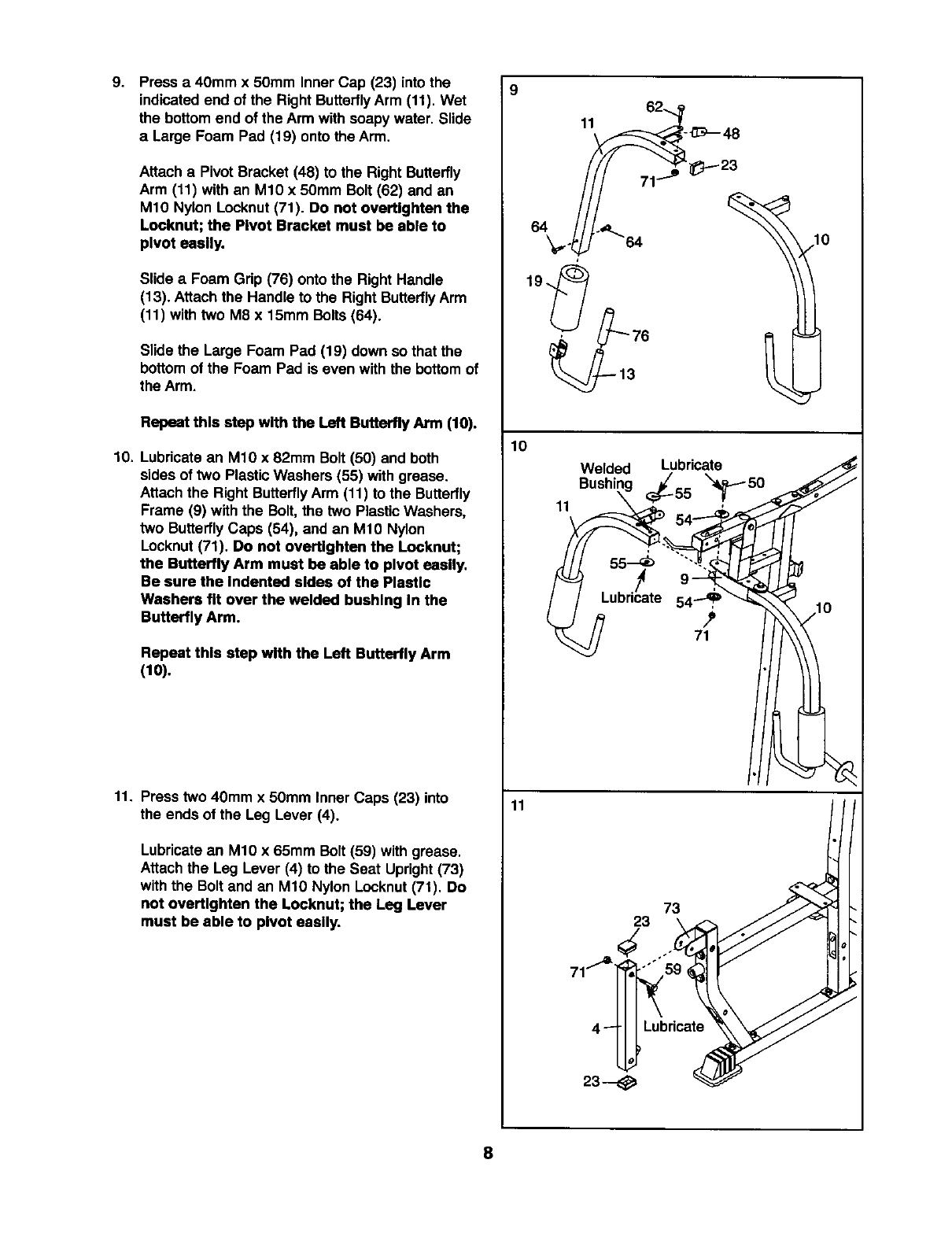
Press a 40mm x 50mm Inner Cap (23) intothe
indicatedend of the RightButterflyArm (11). Wet
the bottom end of the Arm with soapy water. Slide
a Large Foam Pad (19) onto the Arm.
Attach a Pivot Bracket (48) to the Right Butterfly
Arm (11) with an M10 x 50mm Bolt (62) and an
M10 Nylon Locknut(71). Do not overtlghten the
Looknut; the Pivot Bracket must be able to
pivot easily.
Slide aFoam Grip (76) onto the Right Handle
(13). Attachthe Handle to the Right ButterflyArm
(11) withtwo M8 x 15ram Bolts (64).
Slide the Large Foam Pad (19) down so that the
bottom of the Foam Pad is even with the bottom of
the Arm.
Repeat this step with the Left Butterfly Arm (10).
10. Lubricate an M10 x 82mm Bolt (50) and both
sides of two PlasticWashers (55) with grease.
Attach the Right ButterflyArm (11) to the Butterfly
Frame (9) withthe Bolt, the two PlasticWashers,
two ButterflyCaps (54), and an M10 Nylon
Locknut(71). Do not overtlghten the Locknut;
the Butterfly Arm must be able to pivot easily,
Be sure the indented sides of the Plastic
Washers fit over the welded bushing In the
Butterfly Arm.
Repeat this step with the Left Butterfly Arm
(10).
11. Press two 40mm x 50mm Inner Caps (23) into
the ends of the Leg Lever (4).
Lubricatean M10 x 65mm Bolt (59) with grease.
Attach the Leg Lever (4) to the Seat Upright(73)
with the Bolt and an M1O Nylon Locknut(71). Do
not overt_ghten the Locknut; the Leg Lever
must be able to pivot easily.
11
10
11
11
Welded Lubricate
Bushir x'_50
'l
55_ """-
9"" i
Lubricate
71
73
23
4_Lubricate
23--
8
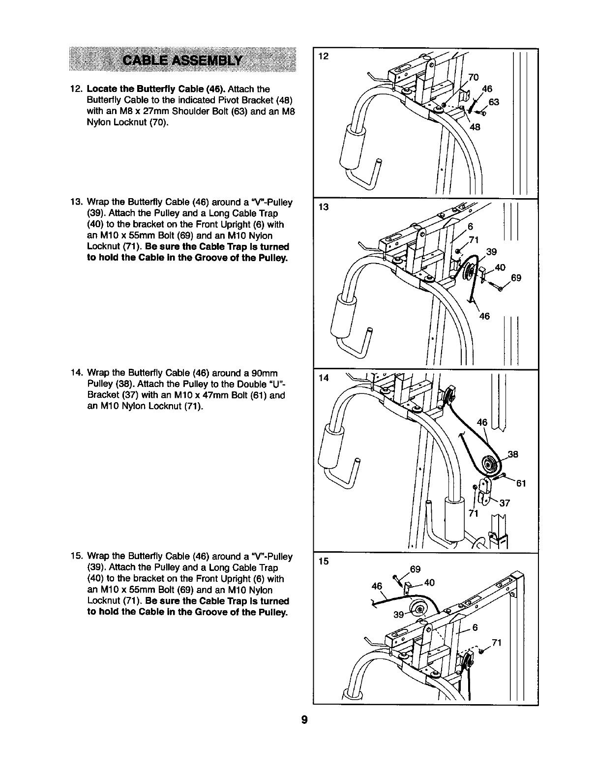
12. Locate the Butterfly Cable (46). Attach the
ButterflyCable to the indicated PivotBracket (48)
with an M8 x 27mm Shoulder Bolt (63) and an M8
Nylon Locknut (70).
13. Wrap the ButterflyCable (46) around a "V"-Pulley
(39). Attach the Pulley and a Long Cable Trap
(40) to the bracket on the Front Upright(6) with
an M10 x 55mm Bolt (69) and an M10 Nylon
Locknut(71). Be sure the Cable Trap Is turned
to hold the Cable In the Groove of the Pulley.
14, Wrap the ButterflyCable (46) around a 90mm
Pulley (38). Attach the Pulley to the Double "U"-
Bracket (37) with an M10 x 47mm Bolt (61) and
an M10 Nylon Locknut(71).
15. Wrap the ButterflyCable (46) around a "V"-Pulley
(39). Attach the Pulley and a Long Cable Trap
(40) to the bracket on the Front Upright(6) with
an M10 x 55mm Bolt (69) and an M10 Nylon
Locknut(71). Be sure the Cable Trap Is turned
to hold the Cable In the Groove of the Pulley.
13
,,6
/71 39
4_/_/69
46
15
46
9
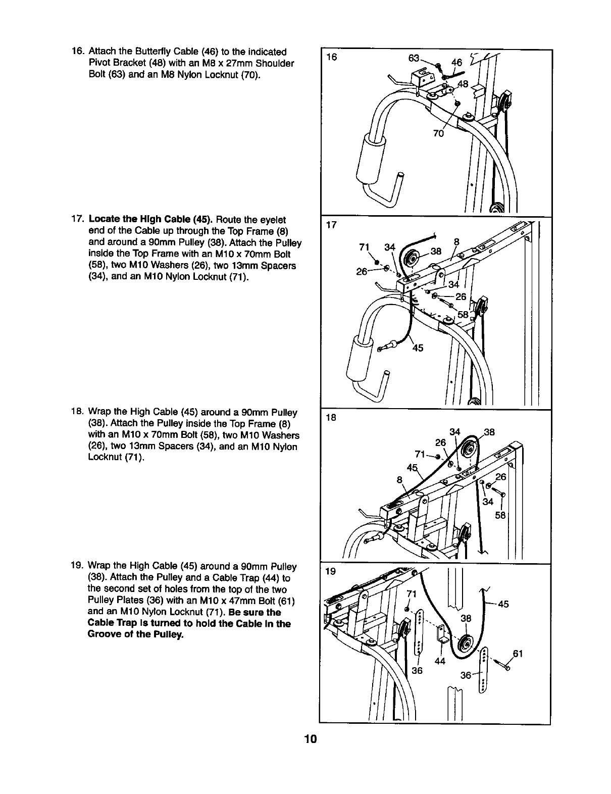
16. Attach the ButterflyCable (46) to the indicated
Pivot Bracket (48) with an M8 x 27mm Shoulder
Bolt (63) and an M8 Nylon Locknut (70).
17. Locate the High Cable (45). Route the eyelet
end of the Cable up throughthe Top Frame (8)
and around a 90mm Pulley (38). Attach the Pulley
inside the Top Frame with an M1O x 7Omm Bolt
(58), two M10 Washers (26), two 13mm Spacers
(34), and an M1O Nylon Locknut(71).
18. Wrap the High Cable (45) around a 90mm Pulley
(38). Attachthe Pulley insidethe Top Frame (8)
withan M10 x 70mm Bolt (58), two M1O Washers
(26), two 13mm Spacers (34), and an M1O Nylon
Locknut (71).
19. Wrap the High Cable (45) around a 90mm Pulley
(38). Attach the Pulley and aCable Trap (44) to
the second set of holes from the top of the two
Pulley Plates (36) with an M10 x 47mm Bolt (61)
and an M10 Nylon Locknut(71). Be sure the
Cable Trap Is turned to hold the Cable In the
Groove of the Pulley.
16
17
71 34
18
19
7O
8
6.,61
36 _
10
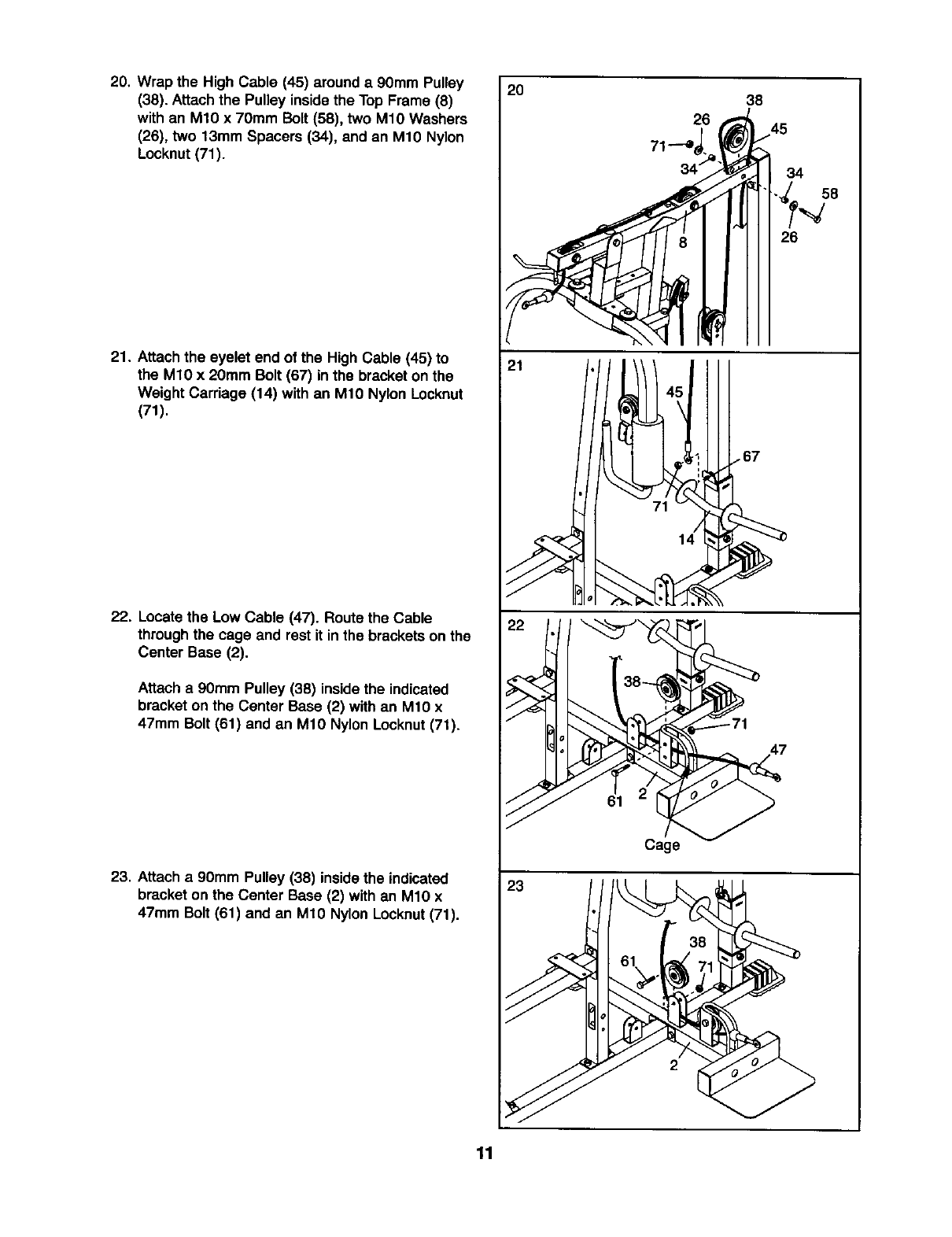
20. Wrap the High Cable (45) around a 9Omm Pulley
(38). Attachthe Pulley insidethe Top Frame (8)
with an M10 x 70mm Bolt (58), two M1OWashers
(26), two 13mm Spacers (34), and an M10 Nylon
Locknut(71).
21. Attach the eyelet end of the High Cable (45) to
the M10 x 20mm Bolt (67) in the bracket on the
Weight Carriage (14) with an M1O Nylon Locknut
(71).
22. Locatethe Low Cable (47). Route the Cable
throughthe cage and rest it inthe bracketson the
Center Base (2).
Attach a 90mm Pulley (38) insidethe indicated
bracket on the Center Base (2) with an M10 x
47mm Bolt (61) and an M10 Nylon Locknut(71).
23. Attach a90mm Pulley (38) insidethe indicated
bracket on the Center Base (2) with an M10 x
47mm Bolt (61) and an M10 Nylon Locknut(71).
2O
21
38
145
34
26
61
Cage
23
38
61 e,;1
11
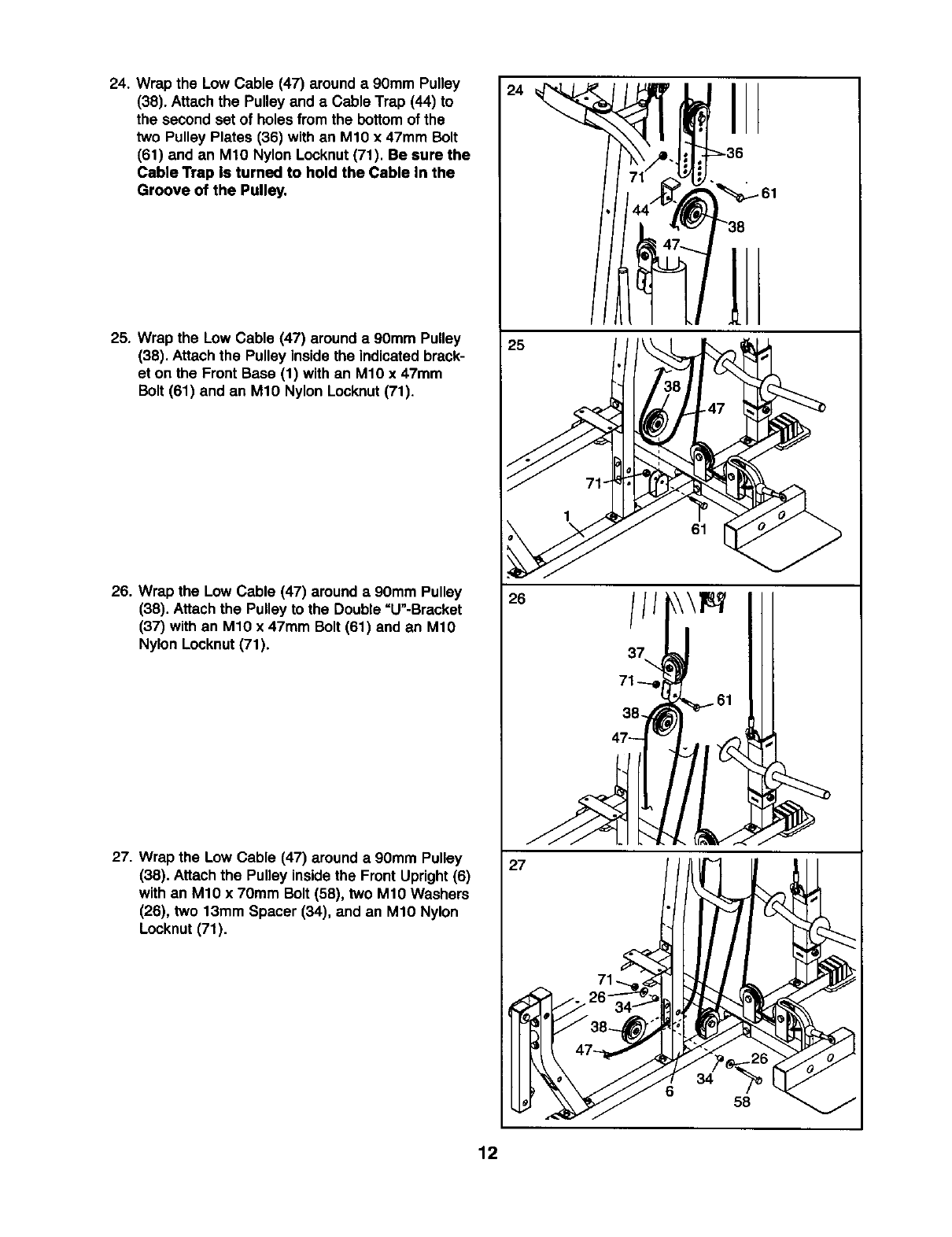
24. Wrap the Low Cable (47) around a90mm Pulley
(38). Attach the Pulley and aCable Trap (44) to
the second set of holes from the bottomof the
two Pulley Plates (36) with an M10 x 47mm Bolt
(61) and an M10 Nylon Locknut(71). Be sure the
Cable Trap Is turned to hold the Cable In the
Groove of the Pulley.
25. Wrap the Low Cable (47) around a 90mm Pulley
(38). Attach the Pulley inside the indicated brack-
et on the Front Base (1) with an M10 x 47mm
Bolt (61) and an M10 Nylon Locknut(71).
26. Wrap the Low Cable (47) around a90mm Pulley
(38). Attachthe Pulley to the Double =U"-Brasket
(37) with an M1O x 47mm Bolt (61) and an M10
Nylon Locknut(71).
27. Wrap the Low Cable (47) around a 90mm Pulley
(38). Attach the Pulley insidethe Front Upright(6)
with an M10 x 70mm Bolt (58), two M10 Washers
(26), two 13mm Spacer (34), and an M10 Nylon
Locknut (71).
24
25
I
61
26
38-_ 61
47_
27
34
658
12
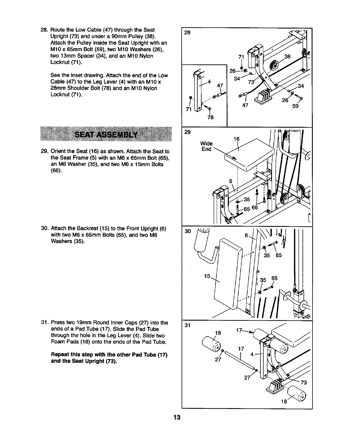
28. Route the Low Cable (47) throughthe Seat
Upright (73) and under a 90mm Pulley (38).
Attach the Pulley insidethe Seat Uprightwith an
M10 x 65mm Bolt (59), two M10 Washers (26),
two 13mm Spacer (34), and an M10 Nylon
Locknut(71).
See the inset drawing.Attach the end of the Low
Cable (47) to the Leg Lever (4) with an M10 x
28mm Shoulder Bolt (78) and an M10 Nylon
Locknut (71).
29. Orient the Seat (16) as shown. Attachthe Seat to
the Seat Frame (5) with an M6 x 65mm Bolt (65),
an M6 Washer (35), and two M6 x 15mm Bolts
(66).
30. Attachthe Backrest(15) to the FrontUpright (6)
withtwo M6 x 65mm Bolts(65), and two M6
Washers (35).
31. Press two 19mm Round Inner Caps (27) into the
ends of a Pad Tube (17). Slide the Pad Tube
throughthe hole in the Leg Lever (4). Slide two
Foam Pads (18) onto the ends of the Pad Tube.
Repeat this step with the other Pad Tube (17)
and the Seat Upright (73).
28
T_4 47
78
29
30
31
47 59
Wide 1_
End _
5
66
II 5 Ill
18
27
18
13
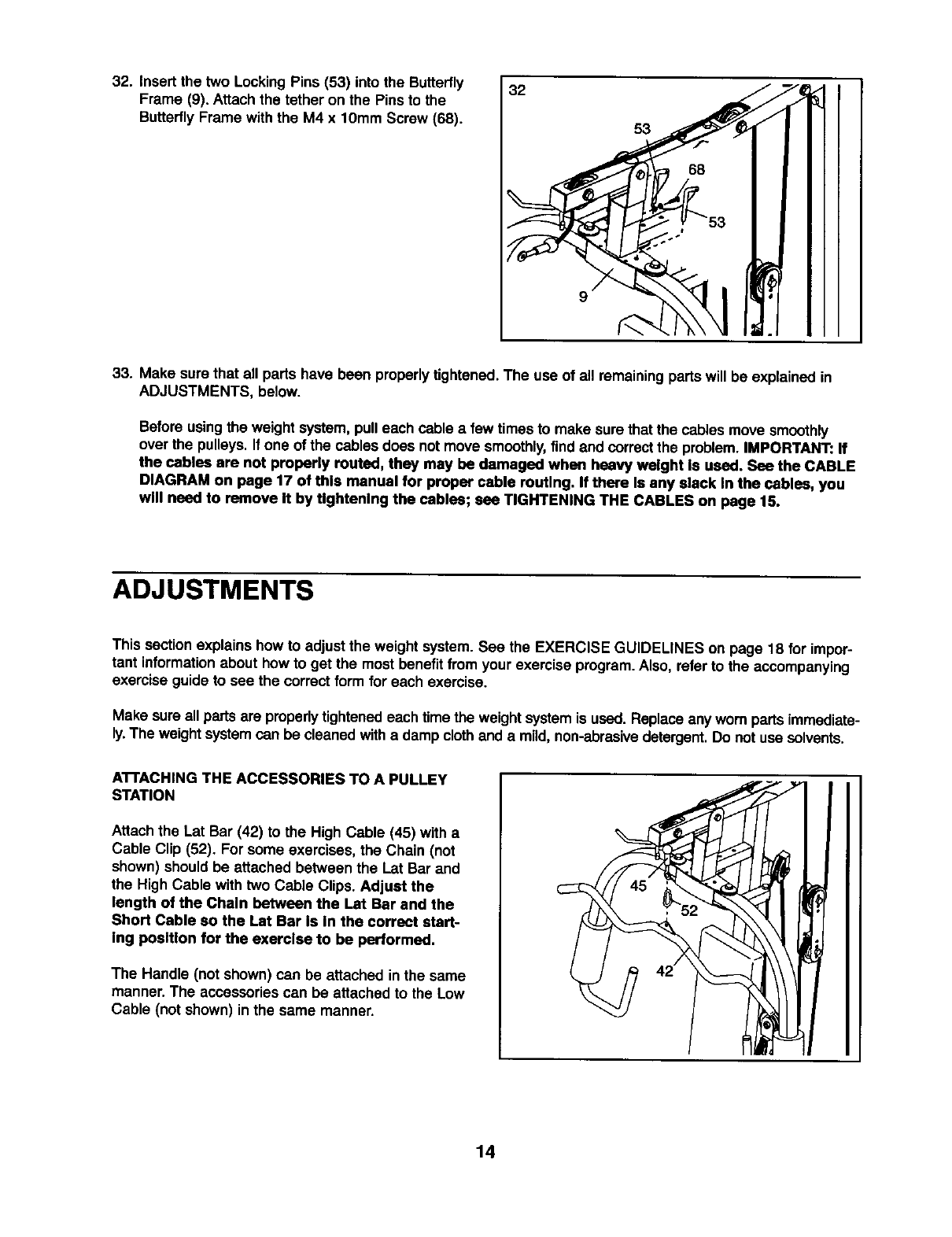
32. Insert the two LockingPins (53) into the Butterfly
Frame (9). Attach the tether on the Pins to the
Butterfly Frame with the M4 x 10mm Screw (68).
32
9
53
33. Make sure that all parts have been properlytightened.The use of all remainingparts will be explained in
ADJUSTMENTS, below.
Before usingthe weight system, pulleach cable afew times to make surethat the cablesmove smoothly
over the pulleys. If one of the cables does not move smoothly,find and correctthe problem.IMPORTANT: If
the cables are not properly routed, they may be damaged when heavy weight Is used. See the CABLE
DIAGRAM on page 17 of this manual for proper cable routing. If there Is any alack In the cables, you
wM need to remove It by Ughtenlng the cables; see TIGHTENING THE CABLES on page 15.
ADJUSTMENTS
This sectionexplains how to adjust the weight system. See the EXERCISE GUIDELINES on page 18 for impor-
tant informationabout how to get the mostbenefitfrom yourexercise program.Also, refer to the accompanying
exercise guide to see the correct form for each exercise.
Make sure all partsare properly tightenedeach time the weightsystem is used. Replace any worn partsimmediate-
ly.The weight systemcan be cleaned witha damp clothand a mild,non-abrasivedetergent.Do not use solvents.
A'n'ACHING THE ACCESSORIES TO A PULLEY
STATION
Attach the Lat Bar (42) to the High Cable (45) with a
Cable Clip (52). For some exercises, the Chain (not
shown) should be attached between the Lat Bar and
the High Cable with two Cable Clips. Adjust the
length of the Chain between the Lat Bar and the
Short Cable so the Lat Bar Is In the correct start-
ing position for the exercise to be performed.
The Handle (not shown) can be attached in the same
manner. The accessoriescan be attached to the Low
Cable (not shown) in the same manner.
14
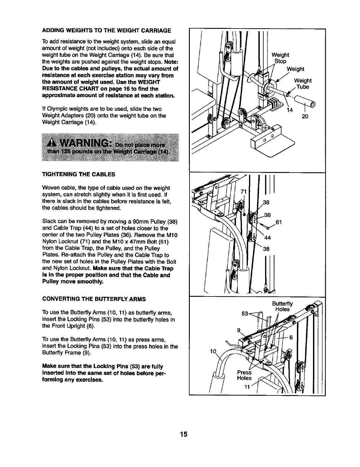
ADDING WEIGHTS TO THE WEIGHT CARRIAGE
To add resistanceto the weight system, slide an equal
amount of weight (notincluded)onto each side of the
weight tubeon the WeightCarriage (14). Be sure that
the weightsare pushed against the weight stops. Note:
Due to the cables and pulleys, the actual amount of
reslstance at each exerclse statlon may vary from
the amount of welght used. Use the WEIGHT
RESISTANCE CHART on page 16 to find the
approxlmate amount of reslstance st each staUon.
If Olympicweights are to be used, slide the two
Weight Adapters (20) onto the weight tube on the
Weight Carriage (14).
TIGHTENING THE CABLES
Woven cable, the type of cable used on the weight
system, can stretch slightlywhen it is firstused. If
there is slack in the cables before resistance is felt,
the cables should be tightened.
Slack can be removed by moving a 90mm Pulley (38)
and Cable Trap (44) to a set of holes closer to the
center of the two Pulley Plates (36). Remove the M10
Nylon Locknut(71) and the M10 x 47mm Bolt (61)
from the Cable Trap, the Pulley, and the Pulley
Plates. Re-attach the Pulley and the Cable Trap to
the new set of holes in the Pulley Plates with the Bolt
and Nylon Locknut. Make sure that the Cable Trap
Is In the proper position and that the Cable and
Pulley move smoothly.
CONVERTING THE BUTTERFLY ARMS
To use the ButterflyArms (10, 11) as butterflyarms,
insertthe Locking Pins (53) intothe butterflyholes in
the Front Upright(6).
To use the ButterflyArms (10, 11) as press arms,
insertthe Locking Pins (53) intothe press holes in the
ButterflyFrame (9).
Make sure that the Locldng Plns (53) are fully
Inserted Into the same set of holes before per-
formlng any exerclses.
I
Weight
Butterfly
Holes
Weight
Weight
20
15
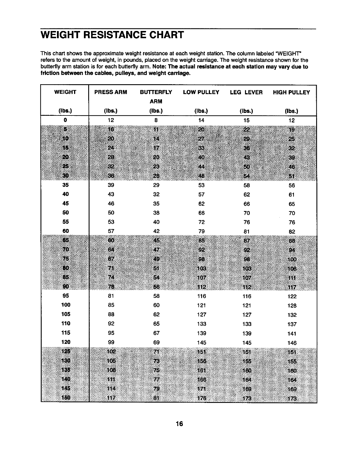
WEIGHT RESISTANCE CHART
This chart showsthe approximate weight resistance at each weight station.The column labeled =WEIGHT"
refers to the amount of weight, in pounds, placed on the weight carriage. The weight resistance shown for the
butterflyarm station is for each butterflyarm. Note: The actual resistance at each station may vary due to
friction between the cables, pulleys, and weight carriage.
WEIGHT
(Ibs.)
0
35
40
45
50
55
60
95
100
105
110
115
120
PRESS ARM BUTTERFLY LOW PULLEY LEG LEVER HIGH PULLEY
ARM
(Ibs.) (Ibs.) (Ibs,) (Ibs,) (Ibs.)
12 8 14 15 12
39 29 53 58 56
43 32 57 62 61
46 35 62 66 65
50 38 66 70 70
53 40 72 76 76
57 42 79 81 82
81 58 116 116 122
85 60 121 121 128
88 62 127 127 132
92 65 133 133 137
95 67 139 139 141
99 69 145 145 146
16
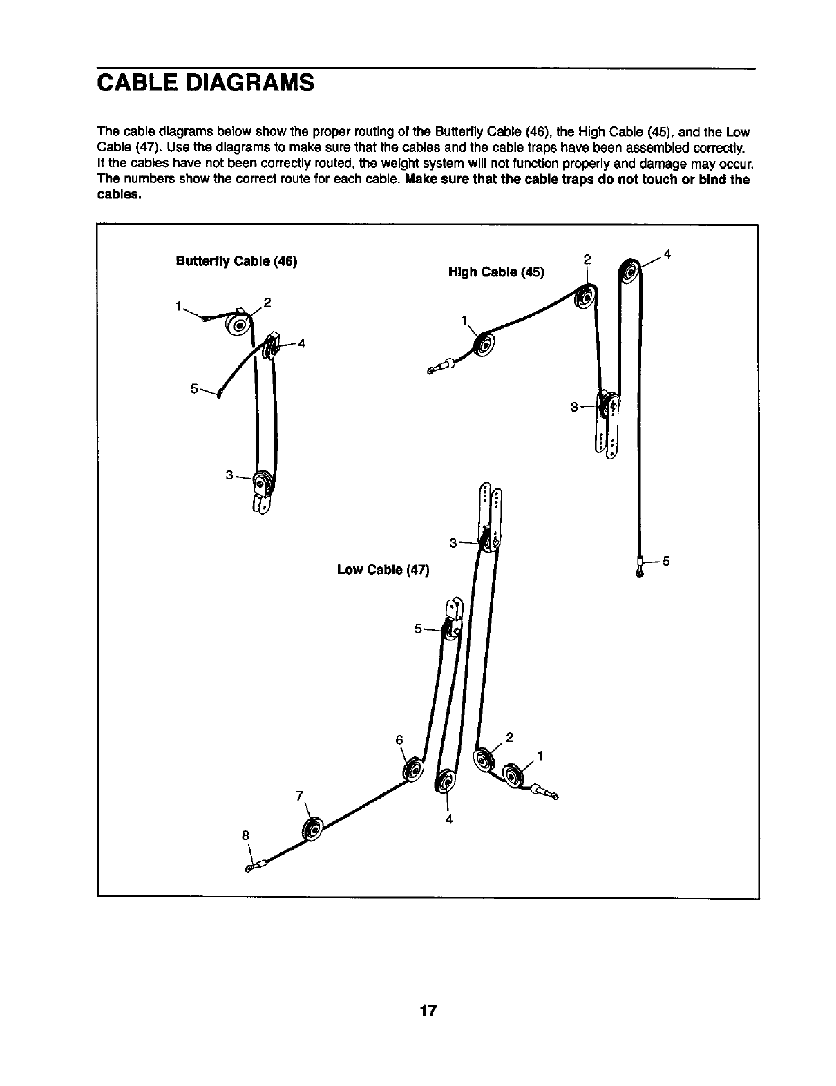
CABLE DIAGRAMS
The cable diagrams below showthe proper routingof the ButterflyCable (46), the High Cable (45), and the Low
Cable (47). Use the diagrams to make sure that the cables and the cable traps have been assembled correctly.
If the cables have not been correctlyrouted, the weight systemwill notfunction properlyand damage may occur.
The numbersshow the correct route for each cable. Make sure that the cable traps do not touch or bind the
cables.
Butterfly Cable (46) High Cable (45)
1
2
8
Low Cable (47)
6
4
2
1
--5
17
EXERCISE GUIDELINES
THE FOUR BASIC TYPES OF WORKOUTS
Muscle Building
To increase the size and strengthof your muscles,
push them close to their maximum capacity.Your mus-
cles will continuallyadapt and grow as you progres-
sively increase the intensityof your exercise. You can
adjust the intensitylevel of an individualexercise in
two ways:
•by changingthe amount of weight used
• by changingthe number of repetitionsor sets per-
formed. (A =repetition" is one complete cycle of an
exercise, such as one sit-up.A "set"is a seriesof
repetitions.)
The proper amount of weight for each exercise
depends upon the individualuser. You mustgauge
your limits and select the amount of weight that is right
for you. Begin with3 sets of 8 repetitionsfor each
exercise you perform. Rest for 3 minutes after each
set. When you can complete 3 sets of 12 repetitions
withoutdifficulty,increase the amount of weight.
Toning
You can tone your musclesby pushingthem to a mod-
erate percentage of their capacity. Select a moderate
amount of weight and increase the number of repeti-
tions in each set. Complete as many sets of 15 to 20
repetitionsas possible withoutdiscomfort.Rest for 1
minute after each set. Work your muscles by complet-
ing more sets rather than by using high amounts of
weight.
Weight Loss
To lose weight, use a low amount of weight and
increase the numberof repetitionsineach set.
Exercise for 20 to 30 minutes, restingfor a maximum
of 30 seconds between sets.
Cross Training
Cross training is an efficient way to get acomplete and
well-balanced fitness program. An example of abal-
anced program is:
•Plan weight trainingworkoutson Monday,
Wednesday, and Friday.
•Plan 20 to 30 minutesof aerobic exercise, such as
cycling or swimming, on Tuesday and Thursday.
•Rest from both weight training and aerobicexercise
for at least one full day each week to give your body
time to regenerate.
The combinationof weight training and aerobic exer-
cise will reshape and strengthen your body, plus devel-
op your heart and lungs.
PERSONALIZING YOUR EXERCISE PROGRAM
Determiningthe exact lengthof time for each workout,
as well as the number of repetitionsor sets completed,
is an individualmatter. It is importantto avoid overdo-
ing it duringthe firstfew monthsof your exercise pro-
gram. You shouldprogress at your own pace and be
sensitiveto your body's signals. If you experience pain
or dizziness at any time while exercising,stop immedi-
ately and begin coolingdown. Findout what is wrong
before continuing. Remember that adequate rest and a
proper diet are importantfactorsin any exercise pro-
gram.
WARMING UP
Begin each workoutwith 5 to 10 minutes of stretching
and lightexerciseto warm up. Warming up prepares
your body for more strenuousexercise by increasing
circulation,raising your body temperature and deliver-
ing more oxygen to your muscles.
WORKING OUT
Each workoutshould include 6 to 10 differentexercis-
es. Select exercises for every major musclegroup,
emphasizing areas that you want to develop most.To
give balance and varietyto your workouts, vary the
exercisesfrom sessionto session.
Schedule your workoutsfor the time of day when your
energy level is the highest. Each workoutshould be
followed by at least one day of rest.Once you find the
schedule that is rightfor you, stickwith it.
EXERCISE FORM
Maintainingproper form is an essential part of an
effective exercise program.This requires moving
throughthe full range of motionfor each exercise, and
moving only the appropriate partsof the body.
Exercisingin an uncontrolledmanner will leave you
feeling exhausted. On the exercise guide accompany-
ing this manual you will find photographsshowingthe
correct form for several exercises, and a listof the
muscles affected. Refer to the muscle chart on page
19 to find the names of the muscles.
The repetitions in each set should be performed
smoothlyand without pausing.The exertion stage of
each repetition should last about half as long as the
return stage. Proper breathing is important. Exhale
during the exertion stage of each repetition and inhale
during the return stroke. Never hold your breath.
18
Rest for a short period of time after each set. The
ideal restingperiods are:
•Rest for three minutes after each set for a muscle
buildingworkout.
•Rest for one minute after each set for a toning work-
out.
•Rest for 30 seconds after each set for a weight loss
workout.
Plan to spend the firstcouple of weeks familiarizing
yourself withthe equipment and learningthe proper
form for each exercise.
COOLING DOWN
End each workoutwith 5 to 10 minutesof stretching.
Include stretchesfor both your arms and legs. Move
slowly as you stretchand do not bounce. Ease into
each stretchgradually and go only as far as you can
without strain. Stretching at the end of each workout
is an effective way to increase flexibility.
STAYING MOTIVATED
For motivation,keep a recordof each workout, listthe
date, the exercises performed,the weight used, and
the numbers of sets and repetitionscompleted.
Record yourweight and key body measurements at
the end of every month. Remember, the key to
achieving the greatest results is to make exercise a
regular and enjoyable part of your everyday life.
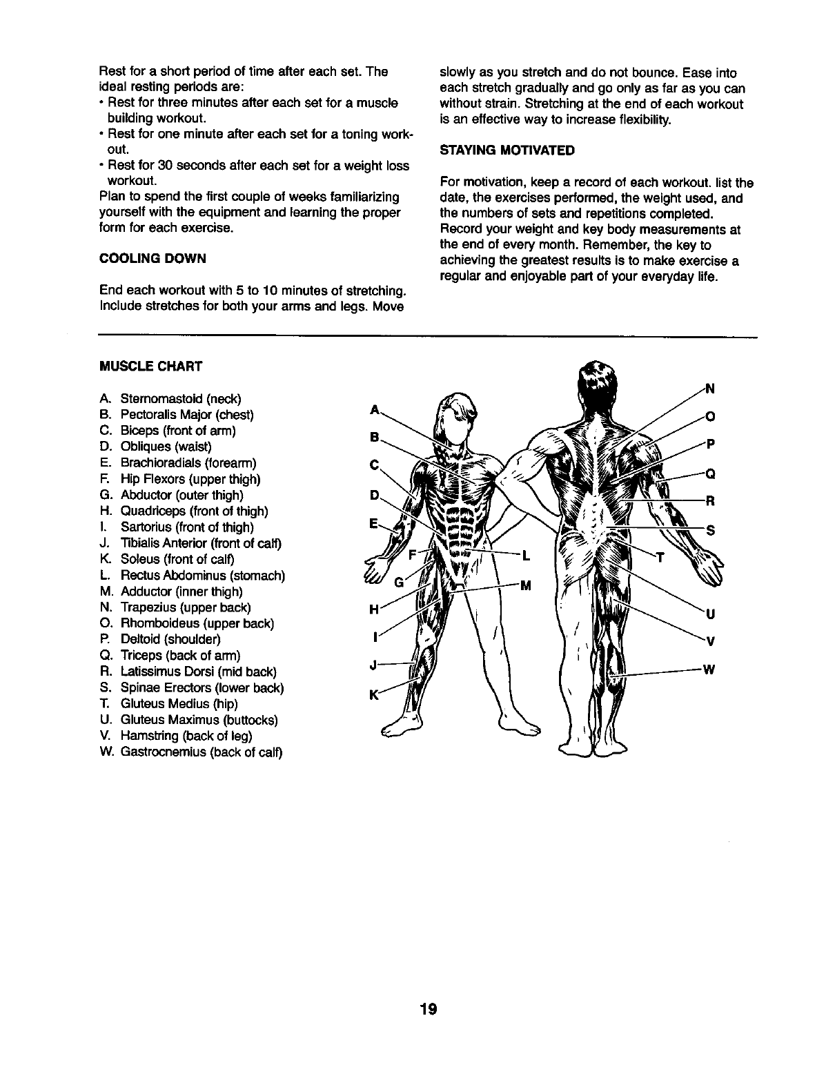
MUSCLE CHART
A. Sternomastoid(neck)
B. PectoralisMajor (chest)
C. Biceps (frontof arm)
D. Obliques(waist)
E. Brachioradials(forearm)
F. Hip Flexors(upperthigh)
G. Abductor(outerthigh)
H. Quaddceps(frontof thigh)
I. Sartorius(frontof thigh)
J. "nbialisAntedor(front of calf)
K. Soleus (frontof calf)
L. RectusAbdominus(stomach)
M. Adductor(innerthigh)
N, Trapezius(upperback)
O. Rhomboideus(upperback)
P. Deltoid(shoulder)
Q. Triceps(back of arm)
R. LatissimusDorsi(mid back)
S. Spinae Erectors(lower back)
T. Gluteus Medius(hip)
U. Gluteus Maximus(buttocks)
V. Hamstring(backof leg)
W. Gastrocnemius(back of calf)
R
S
19
This chart is provided to help you identifythe small parts used in assembly. The number in parenthesisbelow
each part refersto the key number of the partfrom the PART LIST in the center of this manual. Important:
Some parts may have been pre-aesembled for shipping. If you cannot find a part In the parts bags,
check to see If It has been pre-assembled.
Note: Assembly Is divided into four stages: 1) frame assembly, 2) arm
assembly, 3) cable assembly, and 4) seat assembly. The hardware for
each stage Is packaged separately. Walt untll you begln each stage to
open the parts bag for that stage.
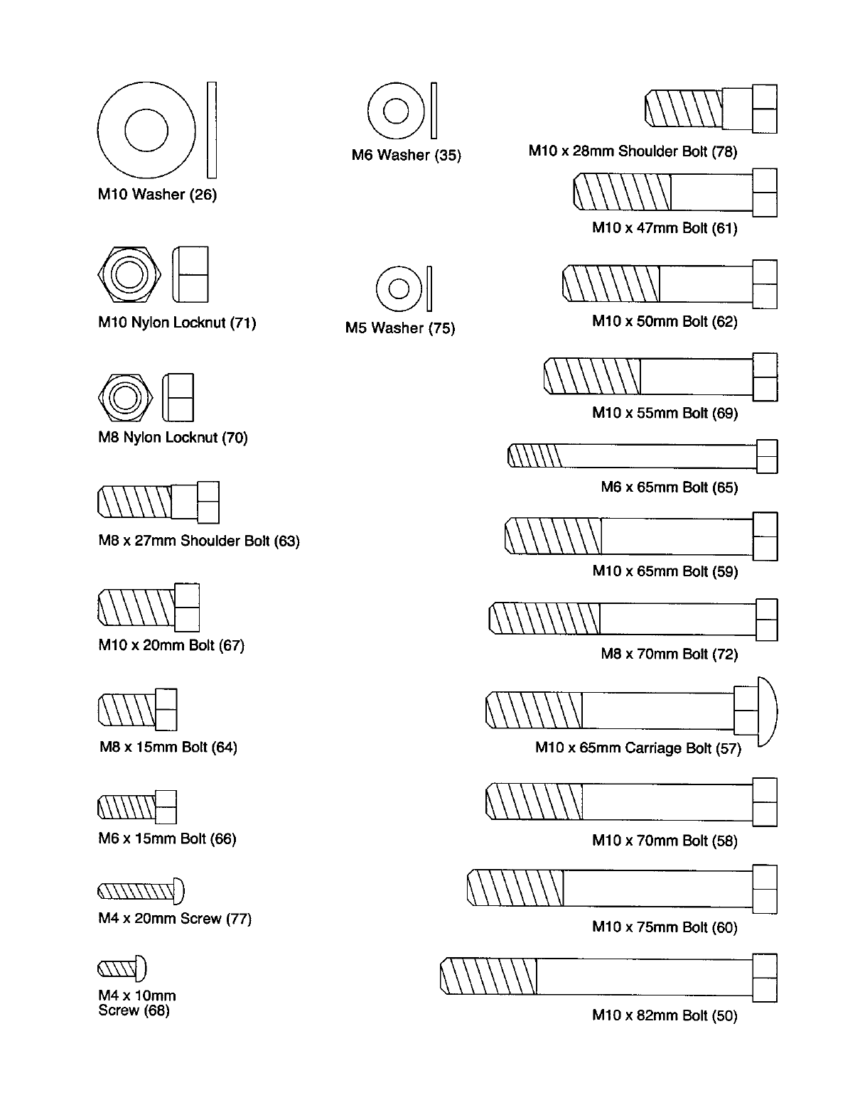
MIO Washer (26)
MIO Nylon Locknut (71)
M6 Washer (35)
©U
M5 Washer (75)
MIO x 28ram Shoulder Bolt (78)
MIO x 47ram Bolt (61)
MIO x 50mm Bolt (62)
@8
M8 Nylon Locknut (70)
M8 x 27ram Shoulder Bolt (63)
MIO x 20mm Bolt (67)
M8 x 15ram Bolt (64)
MIO x 55ram Bolt (69)
M6 x 65ram Bolt (65)
MIO x 65ram Bolt (59) B
M8 x70mm Bolt (72)
MIO x 65mm Carriage Bolt (57_ "/
M6 x 15ram Bolt (66)
M4 x 20ram Screw (77)
MIO x 70ram Bolt (58)
MIO x 75mm Bolt (60)
M4 x lOmm
Screw (68) MIO x 82ram Bolt (50)
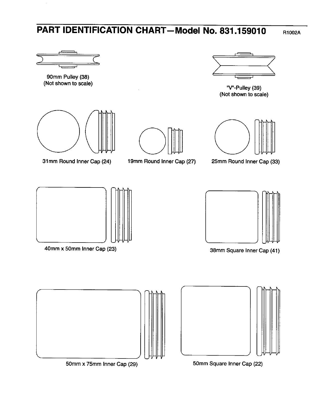
PART IDENTIFICATION CHART--Model No. 831.159010 R10O2A
90mm Pulley (38)
(Not shown to scale) "V"-Pulley (39)
(Not shown to scale)
31ram Round Inner Cap (24) 19ram Round Inner Cap (27) 25ram Round Inner Cap (33)
40ram x 50mm Inner Cap (23) 38ram Square Inner Cap (41)
50mm x 75mm Inner Cap (29) 5Omm Square Inner Cap (22)
SAVE THIS PART LIST/EXPLODED DRAWING FOR FUTURE REFERENCE

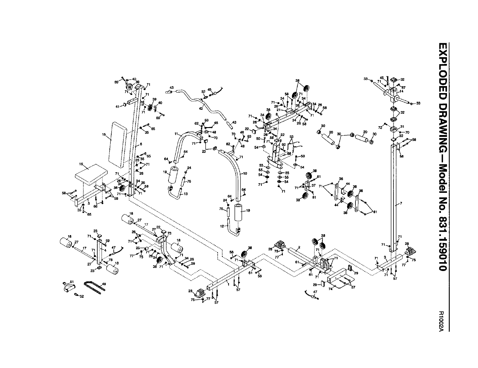
PART LIST--Model No. 831.159010 R1002A
Key No. Qty. Descrtptlon Key No. Qty. Description
1
2
3
4
5
6
7
8
9
10
11
12
13
14
15
16
17
18
19
20
21
22
23
24
25
26
27
28
29
30
31
32
33
34
35
36
37
38
39
40
41
42
4
2
2
1
4
4
2
1
14
4
3
2
4
1
3
2
10
3
2
1
12
2
2
1
1
Front Base 43 2 Handgrip
Center Base 44 2 Cable Trap
Rear Base 45 1 High Cable
Leg Lever 46 1 ButterflyCable
Seat Frame 47 1 Low Cable
Front Upright 48 2 Pivot Bracket
Rear Upright 49 1 Chain
Top Frame 50 2 M10 x 82mm Bolt
ButterflyFrame 51 1 Handle
Left ButterflyArm 52 2 Cable Clip
Right ButterflyArm 53 2 LockingPin
Left Handle 54 4 ButterflyCap
Right Handle 55 4 PlasticWasher
Weight Carriage 56 1 70mm Space Support Plate
Backrest 57 8 M10 x 65mm Carriage Bolt
Seat 58 14 M10 x 70mm Bolt
Pad Tube 59 2 M10 x 65mm Bolt
Foam Pad 60 1 M10 x 75mm Bolt
Large Foam Pad 61 7 M10 x 47mm Bolt
OlympicWeight Adapter 62 2 M10 x 50mm Bolt
90mm Space Support Plate 63 2 M8 x 27mm Shoulder Bolt
50mm Square Inner Cap 64 4 M8 x 15mm Bolt
40mm x 50mm Inner Cap 65 3 M6 x 65ram Bolt
31mm Round Inner Cap 66 2 M6 x 15mm Bolt
Bumper 67 1 M10 x 20mm Bolt
M10 Washer 68 1 M4 x 10mm Screw
19mm Round Inner Cap 69 2 M10 x 55mm Bolt
Base Cap 70 3 M8 Nylon Locknut
50mm x 75mm Inner Cap 71 39 M10 Nylon Locknut
25mm x 50mm Bushing 72 1 M8 x 70mm Bolt
Carriage Stop 73 1 Seat Upright
Carriage Bushing 74 1 Foot Plate
25mm Round Inner Cap 75 4 M5 Washer
13mm Spacer 76 2 Foam Grip
M6 Washer 77 4 M4 x 20mm Screw
Pulley Plate 78 1 M10 x 28mm Shoulder Bolt
Double =U"-Bracket #1 User's Manual
90mm Pulley #1 Exercise Guide
"V"-Pulley #1 Grease Packet
LongCable Trap
38mm Square Inner Cap
Lat Bar
Note: "#" indicatesa non-illustratedpart. Specificationsare subject to change withoutnotice.
66
65
23
18
59
57
57
8
?
o_
o
0
0
0
SEARS
Model No. 831.159010
QUESTIONS?
If you find that:
• you need help assembling or
operating the WELDER"2100
weight system
•a part Is missing
•or you need to schedule repelr
service
call our toll-free HELPLINE
1-800-736-6879
Monday-Saturday, 7 am-7 pm
Central Time (excluding holidays)
REPLACEMENT
PARTS
If parts become worn and need to
be replaced, call the following toll-
free number
1-800-FON-PART
(1-800-366-7278)
The model number and serial number of your WELDER®2100
weight systemare listed on a decal attached to the frame. See
the front cover of this manual to find the locationof the decal.
All replacement parts are available for immediate purchase or
special order when you visityour nearest SEARS Service
Center. To request serviceor to order parts by telephone, call the
toll-free numbers listedat the left.
When requestinghelp or service, or orderingparts, please be
prepared to provide the followinginformation:
•The MODEL NUMBER of the product(831.159010)
• The NAME of the product (WELDER®2100 weight system)
•The KEY NUMBER and DESCRIPTION of the PART (see the
PART LIST and EXPLODED DRAWING in the center of this
manual)
SEARS, ROEBUCK AND CO., HOFFMAN ESTATES, IL 60179
FULL 90 DAY WARRANTY 1
For 90 days from the date of purchase, if failure occurs due to defect in material or workmanshipinthis
SEARS WEIGHT SYSTEM EXERCISER, contact the nearest SEARS Service Center throughoutthe
United States and SEARS will repair or replace the WEIGHT SYSTEM EXERCISER, free of charge
This warranty does not apply when the WEIGHT SYSTEM EXERCISER is used commerciallyor for
rental purposes.
This warranty gives you specificlegal rights, and you may also have other rights which vary from state
to state.
SEARS, ROEBUCK AND CO., DEPT. 817WA, HOFFMAN ESTATES, IL 60179
Part No. 188926 R1002A Printed in China ©2002 Sears, Roebuck and Co.
