Weider Pro 4300 System 14622 Users Manual
2015-05-18
: Weider Weider-Pro-4300-System-14622-Users-Manual-732946 weider-pro-4300-system-14622-users-manual-732946 weider pdf
Open the PDF directly: View PDF ![]() .
.
Page Count: 36
• Assembly
• Adjustment
• Troubleshooting
• Part List and Drawing
Model No. 831.14622.1
Serial No.
Write the serial number in the
space above for future reference.
Serial Number Decal (under seat)
WEIGHT SYSTEM EXERCISER
User’s Manual
CAUTION
Read all precautions and instruc-
tions in this manual before using
this equipment. Keep this manual
for future reference.
Sears, Roebuck and Co.
Hoffman Estates, IL 60179
WARNING DECAL PLACEMENT . . . . . . . . . . . . . . . . . . . . . . . . . . . . . . . . . . . . . . . . . . . . . . . . . . . . . . . . . . . . . .2
IMPORTANT PRECAUTIONS . . . . . . . . . . . . . . . . . . . . . . . . . . . . . . . . . . . . . . . . . . . . . . . . . . . . . . . . . . . . . . . . 3
BEFORE YOU BEGIN . . . . . . . . . . . . . . . . . . . . . . . . . . . . . . . . . . . . . . . . . . . . . . . . . . . . . . . . . . . . . . . . . . . . . . 4
PART IDENTIFICATION CHART . . . . . . . . . . . . . . . . . . . . . . . . . . . . . . . . . . . . . . . . . . . . . . . . . . . . . . . . . . . . . .5
ASSEMBLY . . . . . . . . . . . . . . . . . . . . . . . . . . . . . . . . . . . . . . . . . . . . . . . . . . . . . . . . . . . . . . . . . . . . . . . . . . . . . . 8
ADJUSTMENT . . . . . . . . . . . . . . . . . . . . . . . . . . . . . . . . . . . . . . . . . . . . . . . . . . . . . . . . . . . . . . . . . . . . . . . . . . . 25
WEIGHT RESISTANCE CHART . . . . . . . . . . . . . . . . . . . . . . . . . . . . . . . . . . . . . . . . . . . . . . . . . . . . . . . . . . . . . .27
CABLEDIAGRAM . . . . . . . . . . . . . . . . . . . . . . . . . . . . . . . . . . . . . . . . . . . . . . . . . . . . . . . . . . . . . . . . . . . . . . . . .28
MAINTENANCE . . . . . . . . . . . . . . . . . . . . . . . . . . . . . . . . . . . . . . . . . . . . . . . . . . . . . . . . . . . . . . . . . . . . . . . . . .29
EXERCISE GUIDELINES . . . . . . . . . . . . . . . . . . . . . . . . . . . . . . . . . . . . . . . . . . . . . . . . . . . . . . . . . . . . . . . . . . .30
PARTLIST . . . . . . . . . . . . . . . . . . . . . . . . . . . . . . . . . . . . . . . . . . . . . . . . . . . . . . . . . . . . . . . . . . . . . . . . . . . . . .33
EXPLODEDDRAWING . . . . . . . . . . . . . . . . . . . . . . . . . . . . . . . . . . . . . . . . . . . . . . . . . . . . . . . . . . . . . . . . . . . .34
ORDERING REPLACEMENT PARTS . . . . . . . . . . . . . . . . . . . . . . . . . . . . . . . . . . . . . . . . . . . . . . . . . .Back Cover
90 DAY FULL WARRANTY . . . . . . . . . . . . . . . . . . . . . . . . . . . . . . . . . . . . . . . . . . . . . . . . . . . . . . . . . . Back Cover
TABLE OF CONTENTS
2
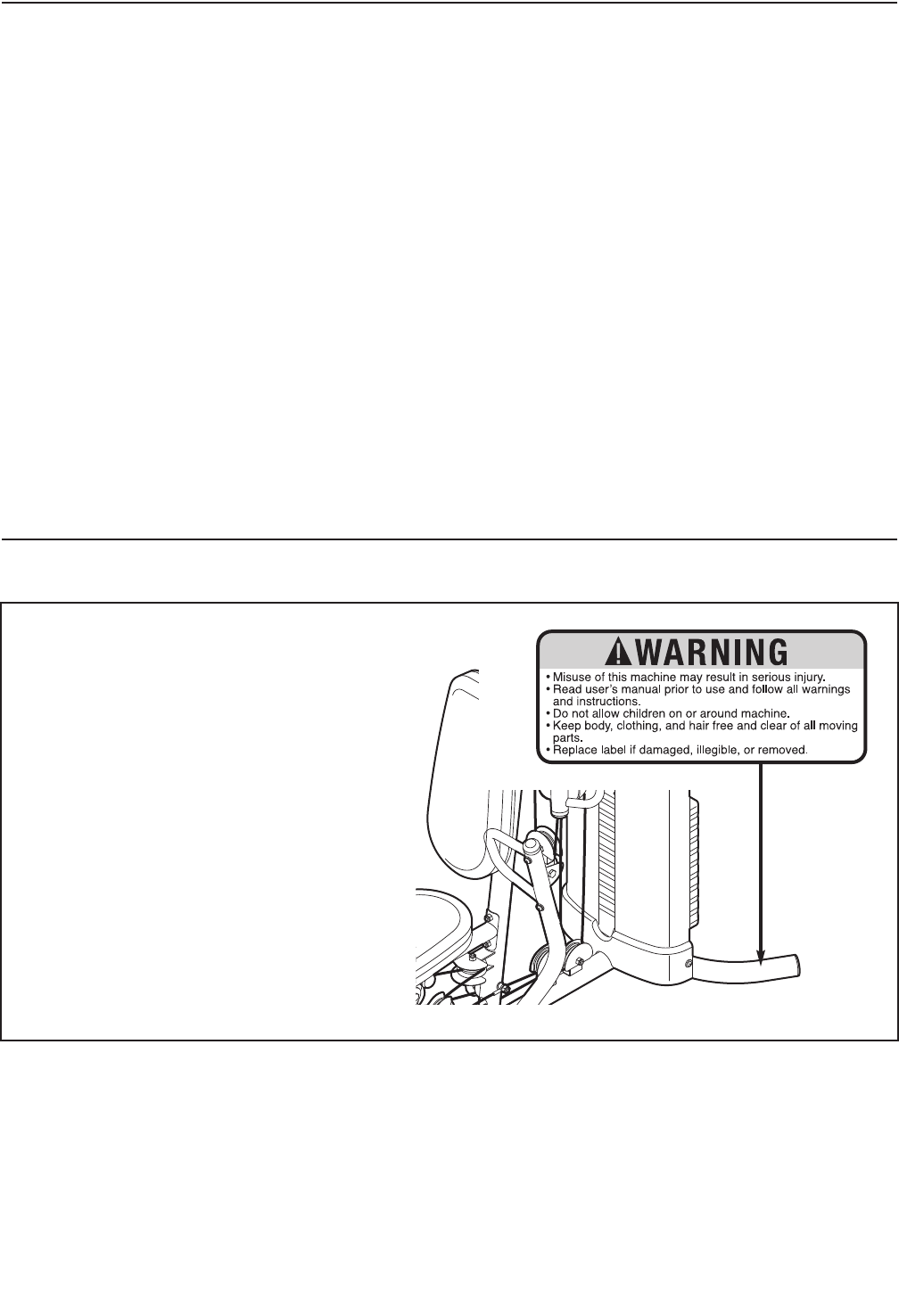
The decal shown here has been applied to
the weight system. If the decal is missing
or illegible, call 1-877-992-5999 and
request a free replacement decal. Apply
the decal in the location shown. Note: The
decal may not be shown at actual size.
WARNING DECAL PLACEMENT

3
1.
Before beginning any exercise program,
consult your physician. This is especially
important for persons over age 35 or per-
sons with pre-existing health problems.
2. Use the weight system only as described in
this manual.
3. It is the responsibility of the owner to ensure
that all users of the weight system are ade-
quately informed of all precautions.
4. The weight system is intended for home use
only. Do not use the weight system in any
commercial, rental, or institutional setting.
5. Keep the weight system indoors, away from
moisture and dust. Place the weight system
on a level surface, with a mat beneath it to
protect the floor or carpet. Make sure that
there is enough clearance around the weight
system to mount, dismount, and use the
weight system.
6. Inspect and properly tighten all parts regu-
larly. Replace any worn parts immediately.
7. Keep hands and feet away from moving
parts.
8. Keep children under age 12 and pets away
from the weight system at all times.
9. Always wear athletic shoes for foot protec-
tion while exercising.
10. Make sure that the cable remains on the pul-
leys at all times. If the cable binds as you
are exercising, stop immediately and make
sure that the cable is on the pulleys. Replace
all cables at least every two years.
11. The weight system is designed to be used
only with the included weight. Do not use
the weight system with dumbbells or any
other type of weight to increase the resist-
ance.
12. The weight system is designed to support a
maximum user weight of 300 lbs. (136 kg).
13. Always make sure that the weight pin is
inserted fully into the weight stack before
exercising.
14. Over exercising may result in serious injury
or death. If you feel faint or if you experience
pain while exercising, stop immediately and
cool down.
WARNING: To reduce the risk of serious injury, read all important precautions and
instructions in this manual and all warnings on your weight system before using your weight sys-
tem. Sears assumes no responsibility for personal injury or property damage sustained by or
through the use of the weight system.
IMPORTANT PRECAUTIONS
4
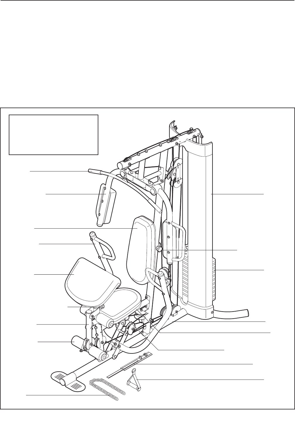
Backrest
Curl Pad
Shroud
Weight
Backrest
Adjustment Knob
Seat Adjustment Knob
Ankle Strap
Handle
Curl Adjustment Knob
Frame
Butterfly Arm
Seat
Right Side Left Side
Note: The terms “right
side” and “left side”
are determined relative
to a person facing
away from the weight
system; they do not
correspond to right
and left on the draw-
ings in the manual.
Leg Lever
Foam Pad
Chain
Press Arm
Lat Bar
BEFORE YOU BEGIN
Thank you for selecting the versatile WEIDER®PRO
4300 weight system. The weight system offers a selec-
tion of weight stations designed to develop every
major muscle group of the body. Whether your goal is
to tone your body, build dramatic muscle size and
strength, or improve your cardiovascular system, the
weight system will help you to achieve the specific
results you want.
For your benefit, read this manual carefully before
using the weight system. If you have questions after
reading this manual, please see the back cover of this
manual. To help us assist you, note the product model
number and serial number before contacting us. The
model number and the location of the serial number
decal are shown on the front cover of this manual.
Before reading further, please review the drawing
below and familiarize yourself with the parts that are
labeled.
ASSEMBLED DIMENSIONS:
Height: 6 ft. 11 in. (210 cm)
Width: 3 ft. 7 in. (109 cm)
Depth: 3 ft. 5 in. (196 cm)
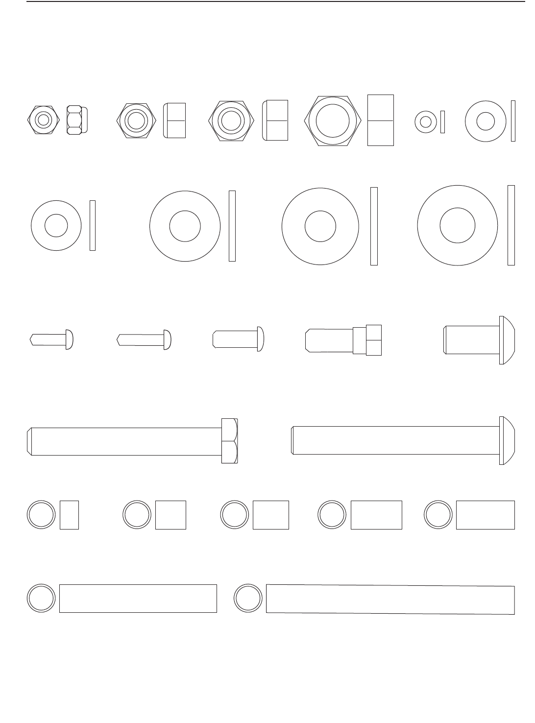
M10 Locknut (77)
M8 Washer (103)
M8 Locknut
(78) M6 Washer
(114)
O
M4 Washer
(104)
M4 x 12mm
Self-tapping
Screw (102)
M4 x 16mm
Self-tapping
Screw (110)
M6 x 16mm
Screw (88) M8 x 22mm
Shoulder Bolt (90)
M10 x 75mm Button Screw (118)
M10 x 20mm
Button Screw (96)
19mm
Spacer (67)
21mm Steel
Spacer (108)
56.5mm Spacer (69) 89.5mm Spacer (59)
M10 Washer (80) M10 Large Washer (105) M12 Large Washer (98)
M10 x 70mm Bolt (113)
11mm
Spacer (99)
13mm Steel
Spacer (109)
7mm
Spacer (111)
M12 Nut (112)
M6 Locknut
(107)
PART IDENTIFICATION CHART
Refer to the drawings below to identify small parts used in assembly. The number in parentheses by each draw-
ing is the key number of the part, from the PART LIST in the center of this manual. Note: Some small parts
may have been preattached. If a part is missing, call 1-877-992-5999.
5
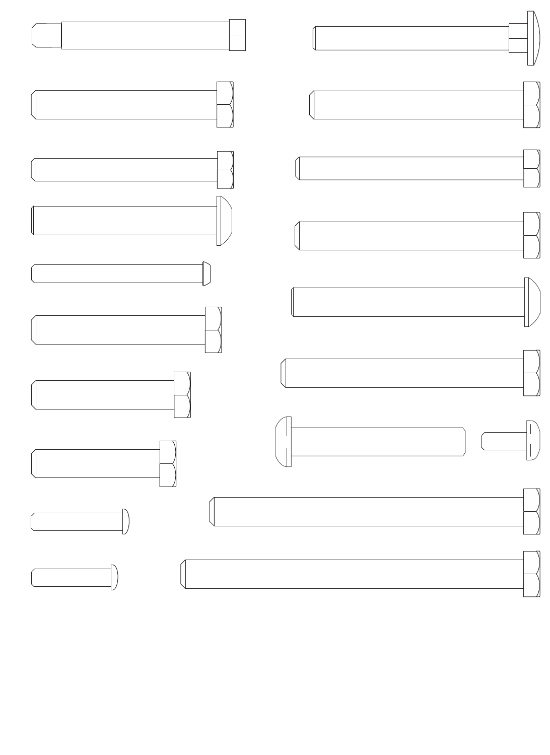
M6 x 32mm Screw (89)
M6 x 28mm
Bolt (94)
M6 x 60mm Button Screw (91)
M8 x 75mm Carriage Bolt (83)
M8 x 80mm Bolt (100)
M8 x 65mm Bolt (101)
M10 x 120mm Bolt (115)
M10 x 82mm Button Screw (92)
M10 x 61mm Bolt Set (116)
M8 x 69mm Shoulder Bolt (87)
M10 x 60mm Bolt (79)
M10 x 85mm Bolt (81)
M10 x 75mm Bolt (82)
M10 x 80mm Bolt (84)
M10 x 65mm Bolt (85)
M10 x 45mm Bolt (86)
M10 x 50mm Bolt (97)
M10 x 110mm Bolt (93)
M10 x 65mm Button Bolt (106)
6
7
Backrest Adjustment Knob (53)
Curl Adjustment Knob (58)
Seat Adjustment Knob (52)

8
The Four Stages of the Assembly Process
Frame Assembly—You will begin by assembling
the base and the uprights that form the skeleton
of the weight system.
Arm Assembly—During this stage you will
assemble the arms and the leg lever.
Cable Assembly—During this stage you will
attach the cables and pulleys that connect the
arms to the weights.
Seat Assembly—During the final stage you will
assemble the seats and the backrests.
ASSEMBLY
To make assembly easier, carefully read the
following information and instructions:
•Assembly requires two persons.
• Because of its size, the weight system should be
assembled in the location where it will be used.
Make sure that there is enough clearance to walk
around the weight system as you assemble it.
• To make assembly as easy as possible, we have
divided the assembly process into four stages.
The parts needed for each stage are found in
individual hardware kits. Place all parts of the
weight system in a cleared area and remove the
packing materials. Do not dispose of the packing.
• Place all parts in a cleared area and remove the
packing materials. Do not dispose of the packing
materials until assembly is completed.
• For help identifying small parts, use the PART
IDENTIFICATION CHART on pages 5 and 6.
• As you assemble the weight system, make sure
all parts are oriented as shown in the drawings.
•Tighten all parts as you assemble them, unless
instructed to do otherwise.
• Assembly requires the included hex key and
grease and the following tools (not included):
two adjustable wrenches
one rubber mallet
one standard screwdriver
one Phillips screwdriver
Assembly may be more convenient if you have a
socket set, a set of open-end or closed-end
wrenches, or a set of ratchet wrenches.
9
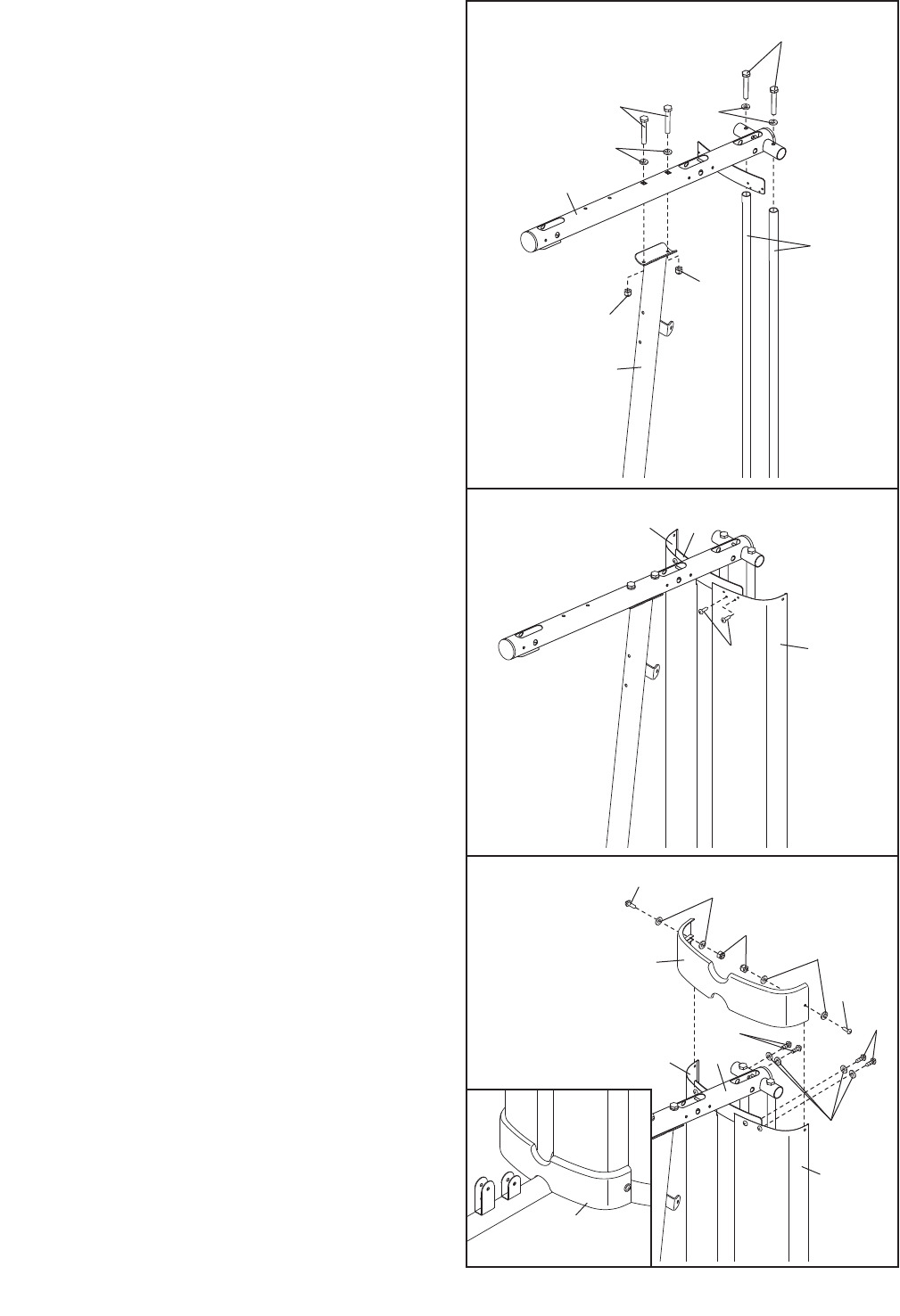
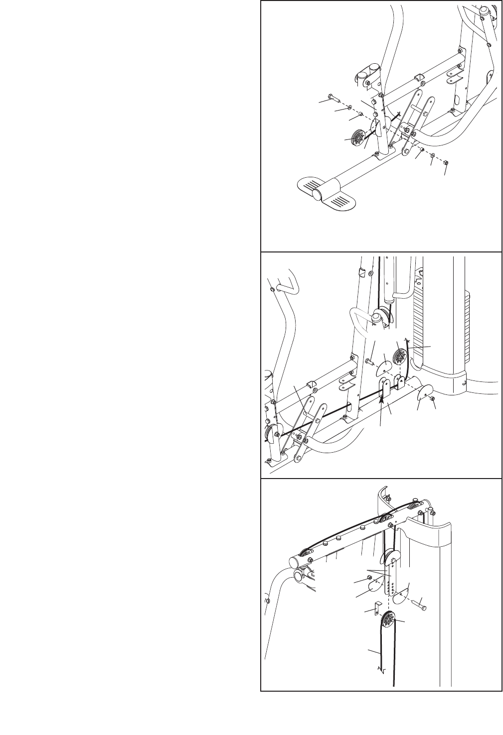
2. Orient the two Weight Guides (18) so that the
indicated holes are closer to the floor, and
insert the Weight Guides into the Stabilizer (3).
Attach the Stabilizer (3) and the Weight Guides
(18) to the Base (1) with two M10 x 85mm Bolts
(81), two M10 Washers (80), two 21mm Steel
Spacers (108), and two M10 Locknuts (77). Do
not tighten the Locknuts yet.
Next, attach the Weight Guides (18) to the
Stabilizer (3) with two M10 x 20mm Button
Screws (96). Then, attach the Stabilizer to the
Base (1) with an M8 x 75mm Carriage Bolt (83)
and an M8 Locknut (78). Do not tighten the
Locknut yet.
Attach the Upright (2) to the Base (1) with the two
indicated M8 x 75mm Carriage Bolts (83) and two
M8 Locknuts (78). Do not tighten the Locknuts
yet.
2
3
10
78
75
104
110
78
1
18
83
1
81
80
80
108
78
78
83
83
96
78
2
3
77
Holes
1
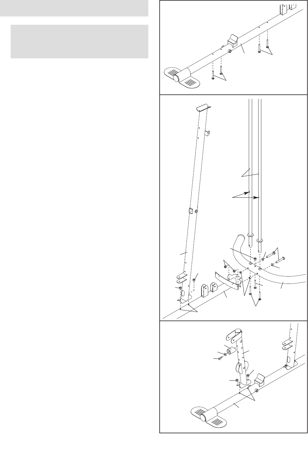
3. Attach the Front Leg (10) to the Base (1) with the
two M8 x 75mm Carriage Bolts (83) and two M8
Locknuts (78). Do not tighten the Locknuts yet.
Attach the Leg Lever Bumper (75) to the Front
Leg (10) with an M4 x 16mm Self-tapping Screw
(110) and an M4 Washer (104). Make sure that
the end of the Leg Lever Bumper is pointing
up.
1.
Insert four M8 x 75mm Carriage Bolts (83) up
through the Base (1). Note: It may be helpful to
place a piece of tape over each Bolt head to
hold it in place.
Before beginning assembly, make sure
that you understand the information in the
box on page 8.
Frame Assembly
83
83
1
10
4. Attach the Frame (9) to the Upright (2) with two
M8 x 80mm Bolts (100), two M8 Washers (103),
and two M8 Locknuts (78). Do not tighten the
Locknuts yet.
Attach the Frame (9) to the Front Leg (10) with
two M8 x 65mm Bolts (101), two M8 Washers
(103), and two M8 Locknuts (78). Do not tighten
the Locknuts yet.
4
5
100
100
2
103
103
78
78
78
78
9
101
103 10
102
21
1
5. Attach the bottom of the Left Shroud (21) to the
Base (1) with two M4 x 12mm Self-tapping
Screws (102).
Repeat this step for the Right Shroud (not
shown).
6
6. Note: Some parts have been removed to show
this step clearly.
Slide the two Weight Bumpers (71) onto the
Weight Guides (18). Orient nine Weights (19) with
the pin holes on the bottom as shown. Slide the
Weights onto the Weight Guides.
Insert the Weight Tube into the nine Weights (19).
Make sure that the pin on the Weight Tube is
oriented as shown.
Lubricate the indicated holes in a Weight (19)
with the included grease packet. Slide the Weight
onto the Weight Guides (18).
19
71
19
20
18
Pin
Pin
Hole
Grease
11
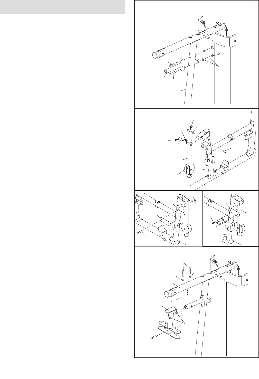
9. Attach a Shroud Cover (23) to the Left and Right
Shrouds (21, 22) with two M6 x 28mm Bolts (94),
four M6 Washers (114), and two M6 Locknuts
(107).
Attach the Shroud Cover (23) to the Top Frame
(4) with four M4 x 16mm Self-tapping Screws
(110) and four M4 Washers (104).
See the inset drawing. Attach the other
Shroud Cover (23) in the same manner.
7
4
2
80
18
103
100
78
78
96
8. Attach the top of the Left Shroud (21) to the Top
Frame (4) with two M4 x 12mm Self-tapping
Screws (102).
Repeat this step for the Right Shroud (22).
8
9
23
7. Attach the Top Frame (4) to the Upright (2) with
two M8 x 80mm Bolts (100), two M8 Washers
(103), and two M8 Locknuts (78). Do not tighten
the Locknuts yet.
Attach the Weight Guides (18) to the Top Frame
(4) with two M10 x 20mm Button Screws (96) and
two M10 Washers (80).
102 21
23
21
94
94 114
107
110 110
104
114
22 4
22 4
12
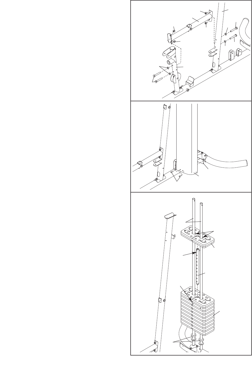
10. Attach the Butterfly Frame Brace (6) to the
Upright (2) with two M8 x 80mm Bolts (100), two
M8 Washers (103), and two M8 Locknuts (78).
Do not tighten the Locknuts yet.
11. Apply grease in the locations shown. Insert a
56.5mm Spacer (69) into the indicated hole in the
Leg Lever (12). Attach the Leg Lever to the Front
Leg (10) with an M10 x 61mm Bolt Set (116).
Make sure that the indicated rod is oriented as
shown.
See the left inset drawing. Attach the Lock Plate
(14) to the Front Leg (10) with the M8 x 69mm
Shoulder Bolt (87), an M8 Washer (103), and an
M8 Locknut (78).
See the right inset drawing. Insert the Lock
Plate Pin (95) through the Lock Plate (14) and the
Leg Lever (12). Attach the tether on the Lock
Plate Pin to the Front Leg (10) with an M4 x
12mm Self-tapping Screw (102).
12. Attach the Butterfly Frame (5) to the Top Frame
(4) with two M8 x 80mm Bolts (100), two M8
Washers (103), and two M8 Locknuts (78). Do
not tighten the Locknuts yet.
Attach the Butterfly Frame (5) to the Butterfly
Frame Brace (6) with an M10 x 75mm Button
Screw (118).
10
11
10
Rod
12
Hole
116
78
6
2
103
100
100
12
103
78
118
103
100
4
5
6
102
103
87
14
10
78
95
10
14
12
Arm Assembly
69
116
Grease
Grease
13
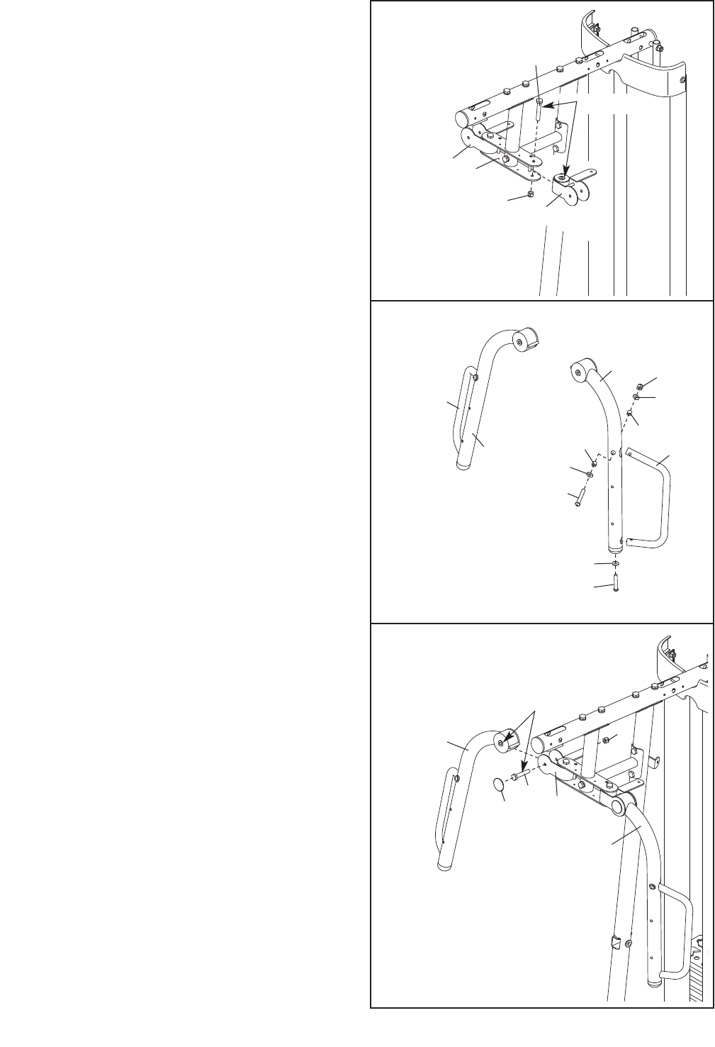
13. Apply grease to the locations shown and attach
the Left Butterfly Bracket (28) to the Butterfly
Frame (5) with an M10 x 80mm Bolt (84) and an
M10 Locknut (77).
Repeat this step for the Right Butterfly
Bracket (29).
See steps 2–13. Tighten the Locknuts (77, 78,
107).
14. Attach a Butterfly Handle (27) to the Left Butterfly
Arm (25) with an M10 x 65mm Button Bolt (106),
two M10 Washers (80), two 13mm Steel Spacers
(109), and an M10 Locknut (77).
Secure the Left Butterfly Arm (25) with an M10 x
82mm Button Screw (92) and an M10 Large
Washer (105).
Repeat this step for the Right Butterfly Arm
and Butterfly Handle (26, 27).
15. Apply grease in the locations shown and attach
the Right Butterfly Arm (26) to the Right Butterfly
Bracket (29) with an M10 x 75mm Bolt (82) and
an M10 Locknut (77). Press a Bolt Cap (44) onto
the end of the Bolt. Do not overtighten the Bolt;
the Butterfly Arm must be able to pivot easily.
Repeat this step for the Left Butterfly Arm (25).
13
14
26
27
77
80
27
80
106
109
109
5
84
77
29
28
105
92
25
15
25
29
77
82
26
44
Grease
Grease
14
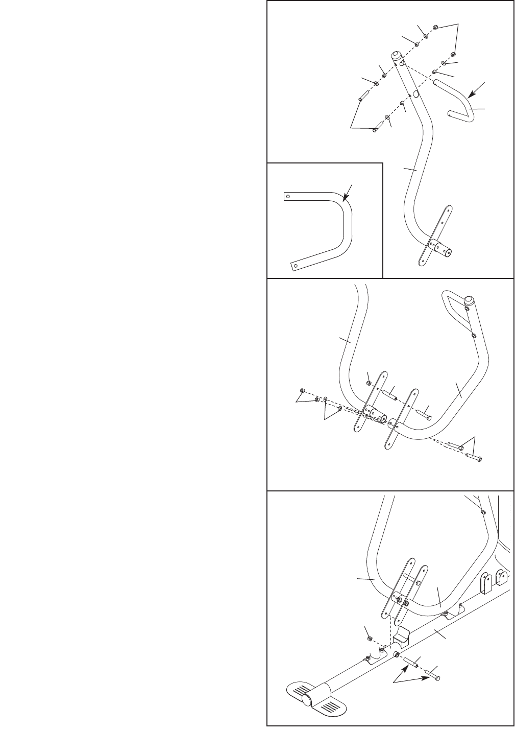
16. Orient a Press Arm Handle (17) with the 90° bend
at the top as shown in the inset drawing. Attach a
Press Arm Handle (17) to the Right Press Arm
(16) with two M10 x 65mm Button Bolts (106),
four M10 Washers (80), four 11mm Spacers (99),
and two M10 Locknuts (77).
Repeat this step for the Left Press Arm (not
shown).
17. Attach the Left Press Arm (15) to the Right Press
Arm (16) with an M10 x 110mm Bolt (93), an
89.5mm Spacer (59) and an M10 Locknut (77).
Finish attaching the Press Arms with two M10 x
65mm Bolts (85), two M10 Washers (80), and two
M10 Locknuts (77). Do not tighten the
Locknuts yet.
18. Attach the Left and Right Press Arms (15, 16) to
the Base (1) with an M10 x 110mm Bolt (93), an
89.5mm Spacer (59), and an M10 Locknut (77).
Do not over tighten the Locknut; the Press
Arms (15, 16) must be able to pivot freely.
See step 17. Tighten the Locknuts (77).
17
16
15
77
77
59
93
80 85
18
16 15
77
1
106
16
99
99
99
80
80
77
99
80
80
17
16
90° Bend
90°
Bend
Grease
59 93
15
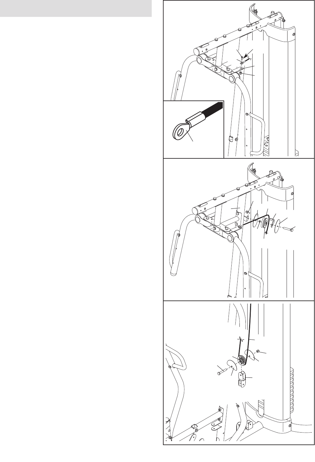
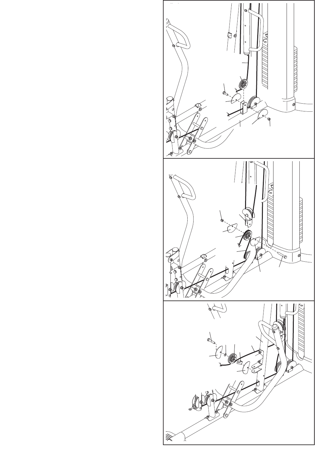
19. See the CABLE DIAGRAMS on page 28 to iden-
tify the cables as you assemble them.
Identify the Butterfly Cable (50). Grease an
M8 x 22mm Shoulder Bolt (90). Attach the Cable to
the Left Butterfly Bracket (28) with the Shoulder Bolt
and an M8 Locknut (78). Make sure that the flat
edge of the Cable is against the Butterfly Arm.
Do not overtighten the Shoulder Bolt; the Cable
must pivot easily.
20. Wrap the Butterfly Cable (50) over a V-pulley
(47). Attach the V-pulley, a Long Cable Trap (57),
an M10 Washer (80), and two Guards (54) to the
Upright (2) with an M10 x 60mm Bolt (79) and an
M10 Locknut (77).
21. Wrap the Butterfly Cable (50) under a 90mm
Pulley (48). Attach the Pulley and two Half
Guards (55) to the Double “U”-bracket (61) with
an M10 x 45mm Bolt (86) and an M10 Locknut
(77). Make sure that the Half Guards are ori-
ented as shown.
19
20
54 50
47
2
80
54
57
79
77
50
78
90 Grease
28
21
48
50
77
55
55 61
86
Cable Assembly
Flat Edge
16
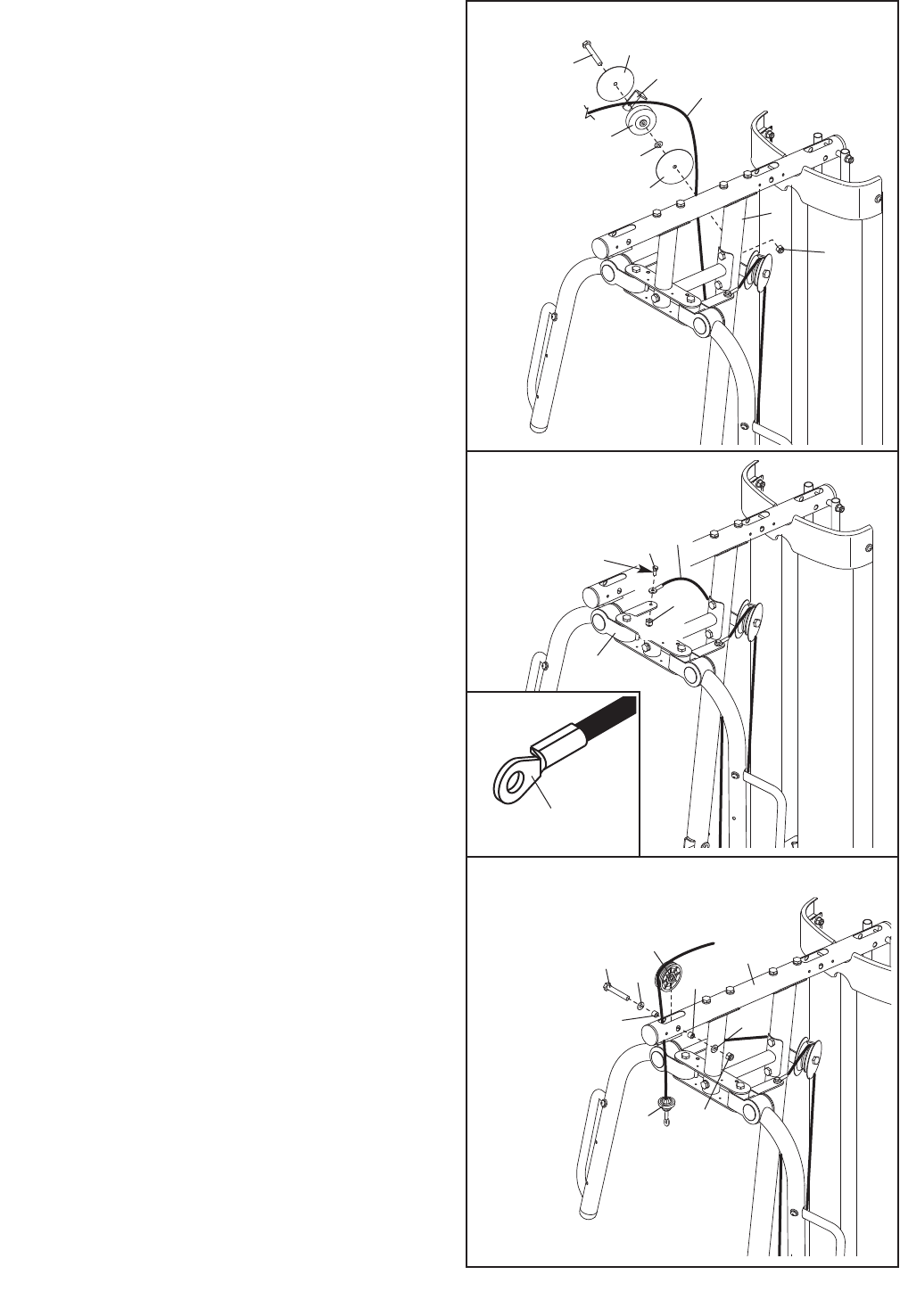
22. Wrap the Butterfly Cable (50) over a V-pulley
(47). Attach the V-pulley, a Long Cable Trap (57),
an M10 Washer (80), and two Guards (54) to the
Upright (2) with an M10 x 60mm Bolt (79) and an
M10 Locknut (77).
23. Grease an M8 x 22mm Shoulder Bolt (90). Attach
the Butterfly Cable (50) to the Right Butterfly Arm
(29) with the Shoulder Bolt and an M8 Locknut
(78). Make sure that the flat edge of the Cable
is against the Butterfly Arm.
24. Identify the Lat Cable (49). Route the Cable up
through the Top Frame (4) and over a 90mm
Pulley (48). Attach the Pulley inside the Top
Frame with an M10 x 80mm Bolt (84), two M10
Washers (80), two 19mm Spacers (67), and an
M10 Locknut (77).
22
23
90 50
29
78
57
50
2
77
54
54
47
80
79
24
84 80
80
77
67
67
48 4
49
Flat Edge
Grease
17
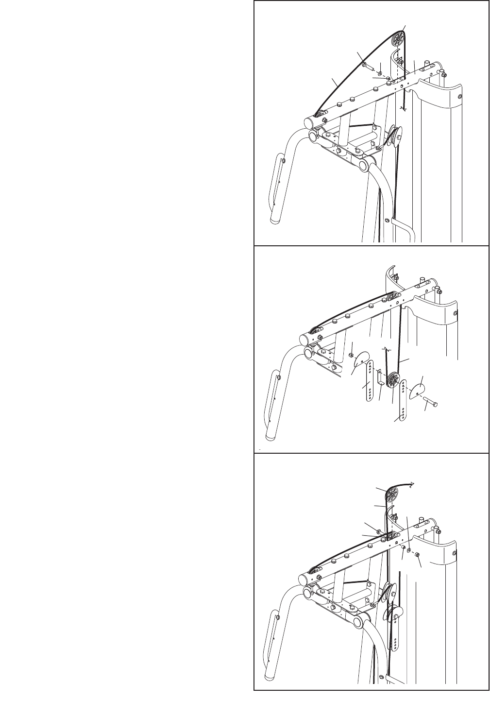
25. Route the Lat Cable (49) over a Thin Pulley (24)
and down through the Top Frame (4). Hold the
Thin Pulley inside the Top Frame. Insert an M10 x
80mm Bolt (84) through an M10 Washer (80), a
19mm Spacer (67), the Top Frame, and the Thin
Pulley.
26. Wrap the Lat Cable (49) under a 90mm Pulley
(48). Attach the Pulley, a Cable Trap (56), and
two Half Guards (55) at the second hole from the
top of the two Pulley Plates (60) with an M10 x
50mm Bolt (97) and an M10 Locknut (77). Make
sure that the Cable Trap and the Half Guards
are oriented as shown.
27. Route the Lat Cable (49) up through the Top
Frame (4) and wrap the Cable over a Thin Pulley
(24). Pull the M10 x 80mm Bolt (84) out of the
Top Frame until it is flush with the first Thin Pulley
from step 24. Do not remove the Bolt com-
pletely from the Top Frame.
Hold the second Thin Pulley (24) inside the Top
Frame (4) and attach it with the M10 x 80mm Bolt
(84), a 19mm Spacer (67), an M10 Washer (80),
and an M10 Locknut (77).
25
26
77
55 55
49
97
4
24
84
80
67
49
60
56 48
60
27
67 77
80
84
49
24
113
18
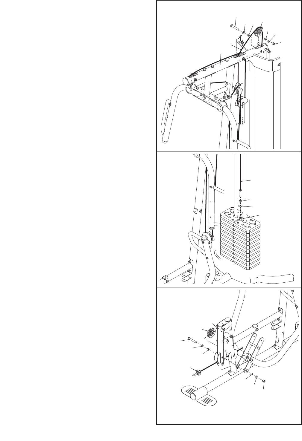
28. Wrap the Lat Cable (49) around a 90mm Pulley
(48) and route the Cable down through the Top
Frame (4). Attach the Pulley to the Top Frame
with an M10 x 80mm Bolt (84), two M10 Washers
(80), two 19mm Spacers (67), and an M10
Locknut (77).
29. Set an M12 Large Washer (98) on top of the
Weight Tube (20). Thread the M12 Nut (112) all
the way onto the Lat Cable (49).
Thread the Lat Cable (49) into the Weight Tube
(20) two turns. Tighten the M12 Nut (112)
against the M12 Large Washer (98).
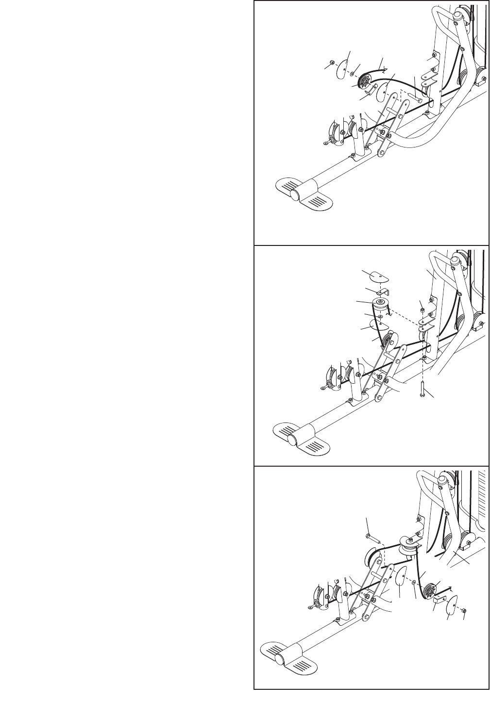
30. Identify the Leg Lever Cable (51). Route the
Cable through the Leg Lever (12) and the Front
Leg (10).
Insert a 90mm Pulley (48) into the Leg Lever (12)
from behind it as shown. Attach the 90mm Pulley
with an M10 x 65mm Bolt (85), two M10 Washers
(80), two 13mm Steel Spacers (109), and an M10
Locknut (77).
28
29
112
98
20
49
80
80
77
48
4
49
67
67
84
30
85
80
12
109
51
77
109
80
48
10
19
31. Attach a 90mm Pulley (48) to the Front Leg (10)
with an M10 x 65mm Bolt (85), two M10 Washers
(80), two 13mm Steel Spacers (109), and an M10
Locknut (77). Make sure that the Leg Lever
Cable (51) is under the Pulley.
32. Route the Leg Lever Cable (51) under the
89.5mm Spacer (59), through the Upright (2), and
under the indicated rod in the Base (1). Wrap the
Leg Lever Cable around a 90mm Pulley (48).
Attach the Pulley to the Base with an M10 x
45mm Bolt (86), two Half Guards (55), and an
M10 Locknut (77).
33. Wrap the Leg Lever Cable (51) over a 90mm
Pulley (48). Attach the Pulley, a Cable Trap (56),
and two Half Guards (55) to the second hole from
the bottom of the Pulley Plates (60) with an M10
x 50mm Bolt (97) and an M10 Locknut (77).
Make sure that the Cable Trap and the Half
Guards are oriented as shown.
31
32
55
59
177
51
85 80
80
77
10
109
109
48
51
Rod
33
77
55
56
55
97
60
51
48
86
55
48
20
34. Wrap the Leg Lever Cable (51) under a 90mm
Pulley (48). Attach the Pulley to the Base (1) with
an M10 x 45mm Bolt (86), two Half Guards (55),
and an M10 Locknut (77).
35. Wrap the Leg Lever Cable (51) over a 90mm
Pulley (48). Attach the Pulley to the Double “U”-
bracket (61) with an M10 x 45mm Bolt (86), two
Half Guards (55), and an M10 Locknut (77).
36. Wrap the Leg Lever Cable (51) under a 90mm
Pulley (48). Attach the Pulley to the Upright (2)
with an M10 x 120mm Bolt (115), two Half Guards
(55), an M10 Washer (80), and a Cable Trap (56).
34
35
77 61
55
55 86
51
48
1
48
55
55
77
51
86
36
115
80 48
56
2
55
55
51
21
37. Wrap the Leg Lever Cable (51) under a 90mm
Pulley (48). Attach the Pulley to the Right Press
Arm (16) with an M10 x 50mm Bolt (97), two Half
Guards (55), a Cable Trap (56), an M10 Washer
(80), and an M10 Locknut (77). Make sure that
the Cable Trap and Half Guards are oriented
as shown.
38. Wrap the Leg Lever Cable (51) around a V-pulley
(47). Attach the Pulley to the Upright (2) with an
M10 x 70mm Bolt (113), two Half Guards (55), an
M10 Washer (80), a Long Cable Trap (57), and
an M10 Locknut (77). Make sure that the Cable
Trap and Half Guards are oriented as shown.
39. Wrap the Leg Lever Cable (51) around a 90mm
Pulley (48). Attach the Pulley to the Left Press
Arm (15) with an M10 x 50mm Bolt (97), two Half
Guards (55), an M10 Washer (80), and a Cable
Trap (56). Make sure that the Cable Trap and
Half Guards are oriented as shown.
37
38
47
80
55
77
2
55
51
113
57
97
55
56
48
77
80
55
16
51
39
55
56 55 77
15
48
51
80
97
22
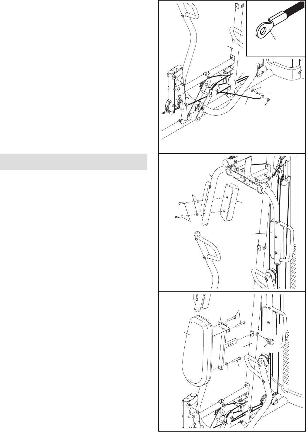
40. Attach the Leg Lever Cable (51) to the Upright (2)
with the M10 x 120mm Bolt (115), an M10
Washer (80), a 7mm Spacer (111), and an M10
Locknut (77). Make sure that the flat edge of
the Cable is against the Spacer.
41. Attach the Right Butterfly Pad (35) to the Right
Butterfly Arm (26) with two M6 x 60mm Button
Screws (91) and two M6 Washers (114).
Repeat this step for the Left Butterfly Pad (34).
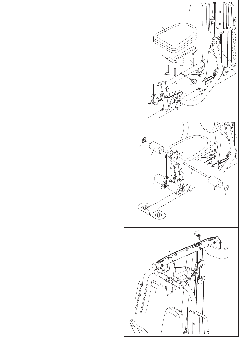
42. Attach the Backrest (31) to the Backrest Frame
(7) with two M6 x 16mm Screws (88), an M6 x
32mm Screw (89), and an M6 Washer (114).
Insert the Backrest Frame (7) into the Upright (2)
and tighten the Backrest Adjustment Knob (53)
into the Upright. Make sure that the Adjustment
Knob passes through one of the holes in the
Backrest Frame.
40
41
26
35
34
114
91
2
51 77
80
111
42
114
89
53
2
7
88
31
Seat Assembly
Flat Edge
115
23
43. Attach the Seat (32) to the Seat Frame (8) with
two M6 x 16mm Screws (88), an M6 x 32mm
Screw (89), and an M6 Washer (114).
Insert the Seat Frame (8) into the Frame (9).
Tighten the Seat Adjustment Knob (52) into the
Frame and the Seat Frame. Make sure that the
Adjustment Knob passes through one of the
holes in the Seat Frame.
44. Insert a Pad Tube (13) into the indicated hole in
the Front Leg (10). Slide a Foam Pad (36) onto
each end of the Pad Tube.
Press a Pad Cap (37) into each Foam Pad (36).
Repeat this step for the other Pad Tube (13)
and the Leg Lever (12). Note: Lift the Leg
Lever Cable (51) when inserting a Pad Tube
through the hole in the bottom of the Leg
Lever.
45. Attach the Butterfly Cover (30) to the Butterfly
Bracket (5) with four M4 x 12mm Self-tapping
Screws (102).
43
44
13
13
51
12
10
36
89
114
32
52
88
9
8
37
36
37
45
30 102
102
5

24
46. Attach the Curl Pad (33) to the Curl Post (11) with
two M6 x 16mm Screws (88).
47. Make sure that all parts have been properly tightened. The use of the remaining parts will be explained in
ADJUSTMENT, beginning on the following page.
Before using the weight system, pull each cable a few times to make sure that the cables move smoothly
over the pulleys. If one of the cables does not move smoothly, find and correct the problem. IMPORTANT: If
the cables are not properly installed, they may be damaged when heavy weight is used. See the
CABLE DIAGRAMS on page 28 of this manual for proper cable routing. If there is any slack in the
cables, you will need to remove the slack by tightening the cables. See MAINTENANCE on page 29.
46
88
11
33
25
This section explains how to adjust the weight system. Refer to the accompanying exercise guide to see the cor-
rect form for several exercises.
Make sure that all parts are properly tightened each time the weight system is used. Replace any worn parts
immediately. The weight system can be cleaned with a damp cloth and a mild, non-abrasive detergent. Do not
use solvents.
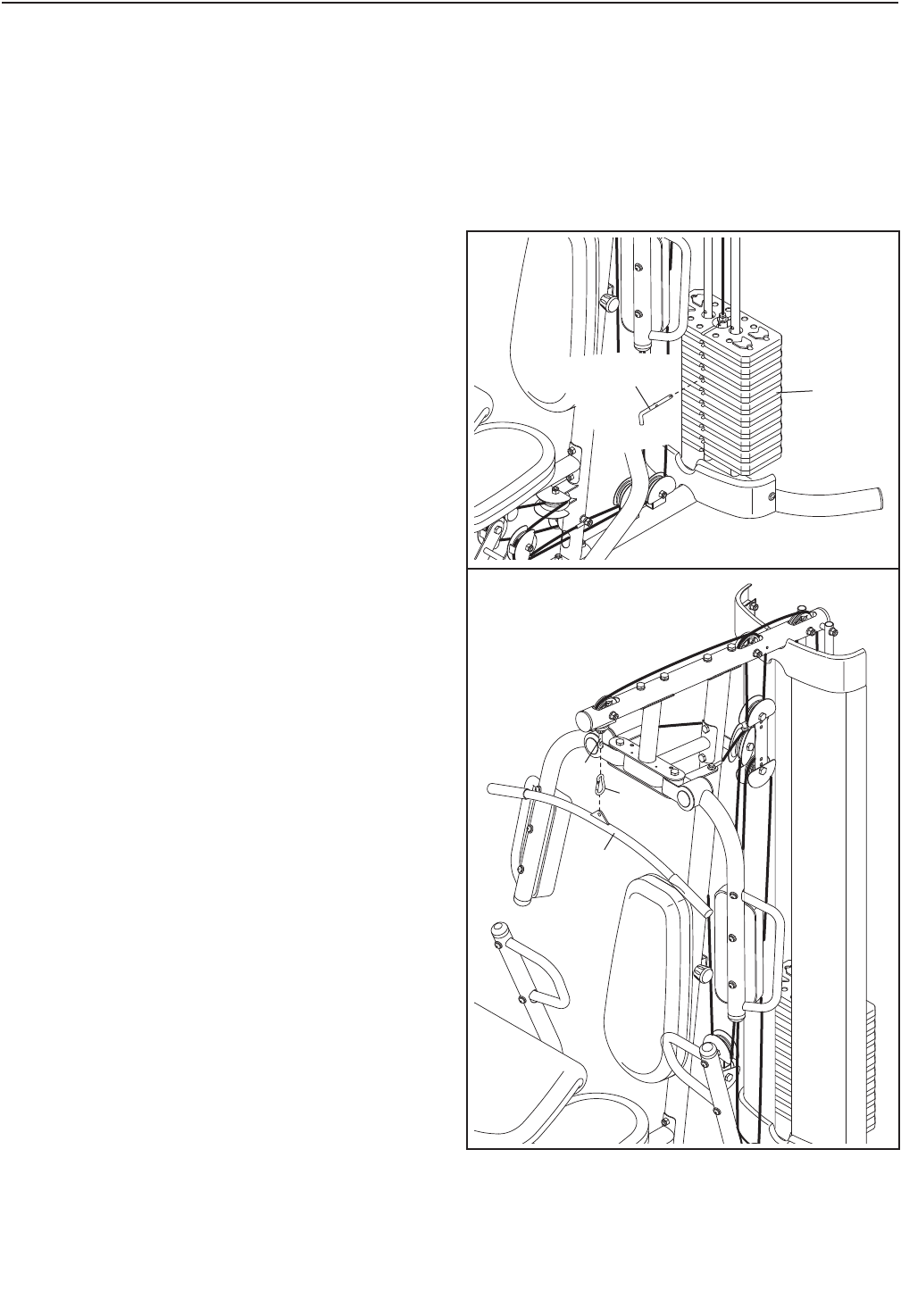
CHANGING THE WEIGHT SETTING
To change the weight setting of the weight stack,
insert the Weight Pin (70) under the desired Weight
(19). Make sure to insert the Weight Pin until the bent
end of the Weight Pin is touching the Weights, and
turn the bent end upward. Note: The weight system
works best when at least two Weights are used.
66
49
19
70
ATTACHING THE ACCESSORIES
To attach the Lat Bar (63) to the Lat Cable (49),
attach a Weight Clip (66) to the Lat Cable and the Lat
Bar. Note: For some exercises, you will need to
attach the Chain (not shown) to the Weight Clip
and use another Weight Clip to attach the Chain
to the Lat Bar.
Attach the other accessories to the weight system
in the same manner.
63
ADJUSTMENT
26
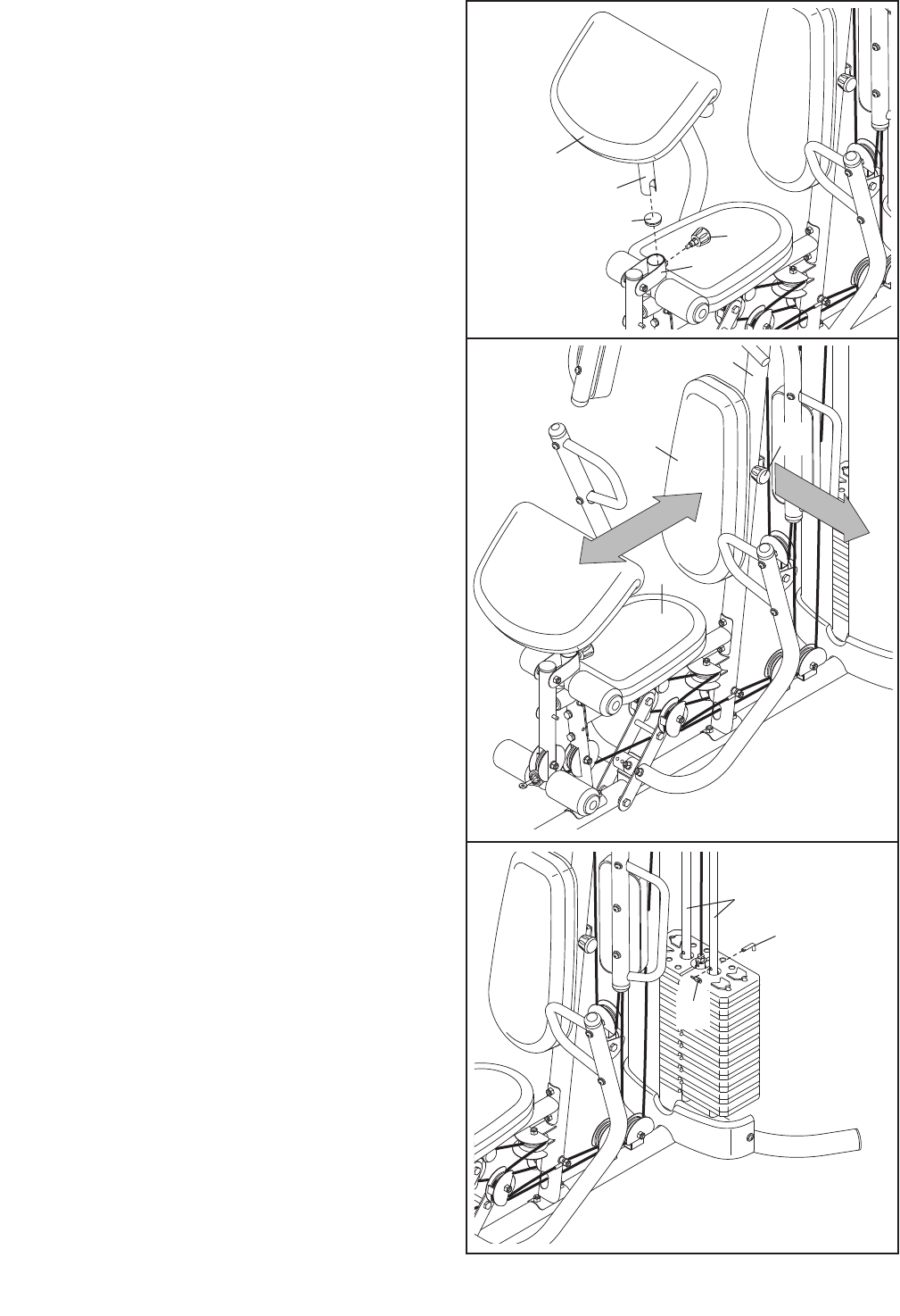
USING THE CURL PAD
To use the Curl Pad (33), remove the indicated 50mm
Round Inner Cap (39) and insert the Curl Post (11)
into the Front Leg (10). Tighten the Curl Adjustment
Knob (58) into the Front Leg. Make sure that the
Adjustment Knob passes through a hole in the Curl
Post.
When you are performing exercises that do not
require the Curl Pad, remove the Curl Pad (33) and
reinsert the 50mm Round Inner Cap (39) into the
Front Leg (10). Note: You must remove the Curl
Pad to use the press arms.
31
32
58
10
39
33
11
ADJUSTING THE BACKREST
To adjust the Backrest, loosen and pull the Backrest
Adjustment Knob (53). Move the Backrest in or out of
the Upright (2), and engage the Adjustment Knob into
the Backrest Frame (not shown). Then, tighten the
Adjustment Knob.
The Seat (32) can be adjusted in the same manner.
LOCKING THE WEIGHT STACK
To lock the weight stack, insert the Locking Pin (72)
through one of the holes in the Guide Rods (18) and
secure the Pin with the Lock (73).
2
53
72
18
73
27
WEIGHT RESISTANCE CHART
The chart below shows the approximate weight resistance at each exercise station. Weight resistance shown for
the butterfly arm station is for each arm. Note: The actual resistance at each station may vary due to differ-
ences in individual weight plates as well as friction between the cables, pulleys, and weight guides.
Note: 1 lb. equals 0.454 kg
WEIGHT
1
2
3
4
5
6
7
8
9
10
HIGH
PULLEY
(lbs.)
26
38
51
62
76
94
124
133
165
178
BUTTERFLY
ARM
(lbs.)
17
24
32
41
48
55
64
71
79
90
PRESS ARM
(lbs.)
46
63
76
90
104
121
138
153
172
195
LEG LEVER
(lbs.)
27
42
54
69
87
103
116
127
135
167
LOW
PULLEY
(lbs.)
25
39
52
67
80
92
111
121
140
168
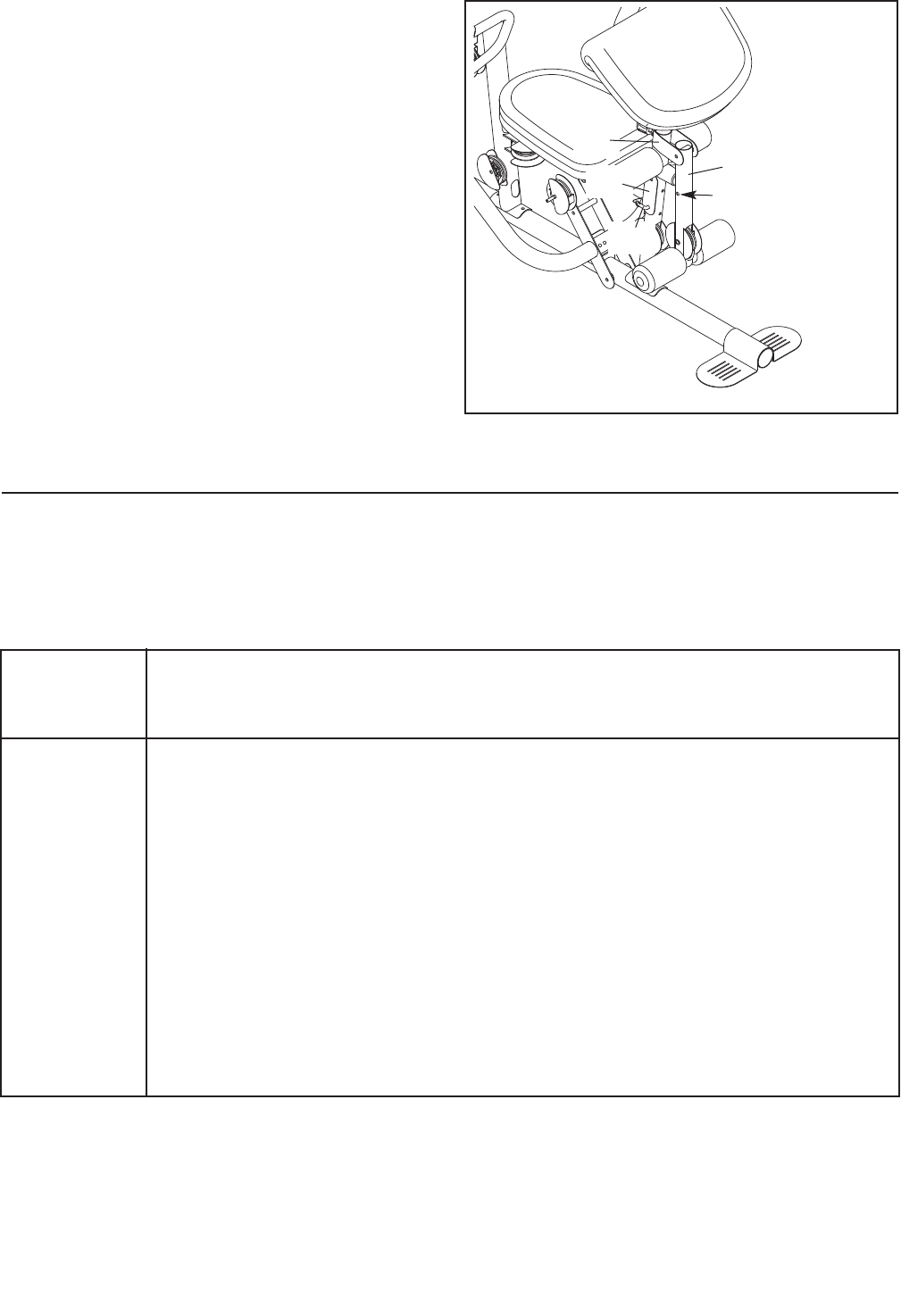
LOCKING THE LEG LEVER
To lock or unlock the Leg Lever, remove the Lock
Plate Pin (95) from the Lock Plate (14). Move the
Lock Plate to either the position shown on the Front
Leg (10), or the indicated hole in the Leg Lever (12).
Insert the Lock Pin back through the Lock Plate.
12
Hole
95
14
10
28
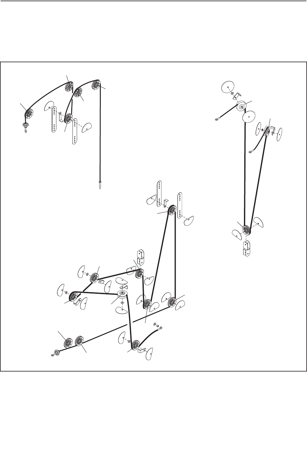
CABLE DIAGRAM
The cable diagram shows the proper routing of the cables. The numbers in each drawing show the proper rout-
ing for that cable. Use the diagram to make sure that the cables and the cable traps are assembled correctly. If
the cables and the cable traps are not assembled correctly, the weight system will not function properly and
damage may occur. Make sure that the cable traps do not touch or bind the cables.
10
6
5
7
89
1
2
3
4
Lat Cable (49)
Length 147 in. (373 cm)
Butterfly Cable (50)
Length 114 in. (289 cm)
Leg Lever Cable (51)
Length 231 in. (588 cm)
1
1
2
3
2
3
4
5
29
Make sure that all parts are properly tightened each time the weight system is used. Replace any worn parts
immediately. The weight system can be cleaned with a damp cloth and a mild, non-abrasive detergent. Do not
use solvents.
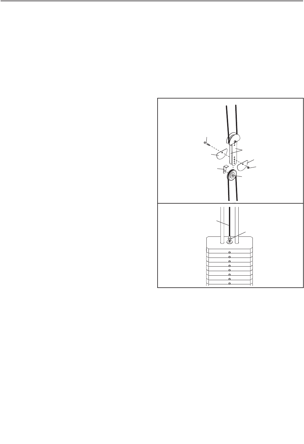
TIGHTENING THE CABLES
Woven cable, the type of cable used on the weight system, can stretch slightly when it is first used. If there is
slack in the cables before resistance is felt, the cables should be tightened. To tighten the cables, first insert the
weight pin into the center of the weight stack. Slack can be removed from the cables several ways:
See drawing 1. Remove the M10 Locknut (77) and
the M10 x 50mm Bolt (97) from the Cable Trap(56),
the 90mm Pulley (48), the two Half Guards (55), and
the two Pulley Plates (60). Reattach the Pulley, Cable
Trap, and Half Guards to the next closer hole to the
center of the Pulley Plates. Make sure that the
Cable Trap is oriented to hold the cable in the
groove of the Pulley, that the Half Guards are ori-
ented as shown, and that the Cable and Pulley
move smoothly.
See drawing 2. Loosen the M12 Nut (112) on the Lat
Cable (49). Tighten the Cable into the Weight Tube
(not shown) until the slack is removed from the Cable.
Retighten the M12 Nut against the M12 Washer (98).
60
55
55
97
77
48
56
49
112
2
Do not overtighten the cables. If the cables are overtightened, the top weight will be lifted off the weight
stack. If a cable tends to slip off the pulleys often, it may have become twisted. Remove the cable and
re-install it. If the cables need to be replaced, see the part ordering information on the back cover of this man-
ual.
MAINTENANCE
1

30
EXERCISE GUIDELINES
FOUR TYPES OF STRENGTH WORKOUTS
Note: A “repetition” is one complete cycle of an exer-
cise, such as one sit-up. A “set” is a series of
repetitions.
Muscle Building—Work your muscles near their max-
imum capacity and progressively increase the intensity
of your exercise. Adjust the intensity level of an individ-
ual exercise as follows:
• Change the amount of resistance used.
• Change the number of repetitions or sets performed.
Use your own judgment to determine the amount of
resistance that is right for you. Begin with 3 sets of 8
repetitions for each exercise that you perform. Rest for
3 minutes after each set. When you can complete 3
sets of 12 repetitions without difficulty, increase the
amount of resistance.
Toning—Tone your muscles by working them to a
moderate percentage of their capacity. Select a mod-
erate amount of resistance and increase the number
of repetitions in each set. Complete as many sets of
15 to 20 repetitions as possible without discomfort.
Rest for 1 minute after each set. Work your muscles
by completing more sets rather than by using high
amounts of resistance.
Weight Loss—To lose weight, use a low amount of
resistance and increase the number of repetitions in
each set. Exercise for 20 to 30 minutes, resting for a
maximum of 30 seconds between sets.
Cross Training—Combine strength training and aero-
bic exercise by following this type of program:
• Strength workouts on Monday, Wednesday, and
Friday.
• 20 to 30 minutes of aerobic exercise on Tuesday
and Thursday.
• One full day of rest each week to give your body
time to regenerate.
WORKOUT GUIDELINES
Familiarize yourself with the equipment and learn the
proper form for each exercise. Use your own judgment
to determine the appropriate length of time for each
workout, and the numbers of repetitions and sets to
complete. Progress at your own pace and be sensitive
to your body’s signals. Follow each strength workout
with at least one day of rest.
Warming Up—Start with 5 to 10 minutes of stretching
and light exercise. A warm-up increases your body
temperature, heart rate, and circulation in preparation
for exercise.
Working Out—Include 6 to 10 different exercises in
each workout. Select exercises for every major muscle
group, emphasizing areas that you want to develop. To
give balance and variety to your workouts, vary the
exercises from workout to workout.
Cooling Down—Finish with 5 to 10 minutes of
stretching. Stretching increases the flexibility of your
muscles and helps to prevent post-exercise problems.
EXERCISE FORM
Move through the full range of motion for each exer-
cise and move only the appropriate parts of the body.
Perform the repetitions in each set smoothly and with-
out pausing. The exertion stage of each repetition
should last about half as long as the return stage.
Exhale during the exertion stage of each repetition and
inhale during the return stroke. Never hold your
breath.
Rest for a short period of time after each set:
• Muscle Building—Rest for three minutes after each
set.
• Toning—Rest for one minute after each set.
• Weight Loss—Rest for 30 seconds after each set.
STAYING MOTIVATED
For motivation, keep a record of each workout. Write
the date, the exercises performed, the resistance
used, and the numbers of sets and repetitions com-
pleted. Record your weight and key body
measurements once a month. To achieve good results,
make exercise a regular and enjoyable part of your
life.

31
EXERCISE LOG
Make copies of this page, and use the copies to schedule and record your strength and aerobic workouts.
Scheduling and recording your workouts will help you to make exercise a regular and enjoyable part of your life.
Exercise Lbs. Sets Reps Exercise Lbs. Sets Reps
1. 6.
2. 7.
3. 8.
4. 9.
5. 10.
Exercise Time Distance Speed
Strength
Date:
Exercise Lbs. Sets Reps Exercise Lbs. Sets Reps
1. 6.
2. 7.
3. 8.
4. 9.
5. 10.
Exercise Lbs. Sets Reps Exercise Lbs. Sets Reps
1. 6.
2. 7.
3. 8.
4. 9.
5. 10.
Strength
Date:
Strength
Date:
Aerobic
Date:
Exercise Time Distance Speed
Aerobic
Date:
Exercise Time Distance Speed
Aerobic
Date:

32
NOTES

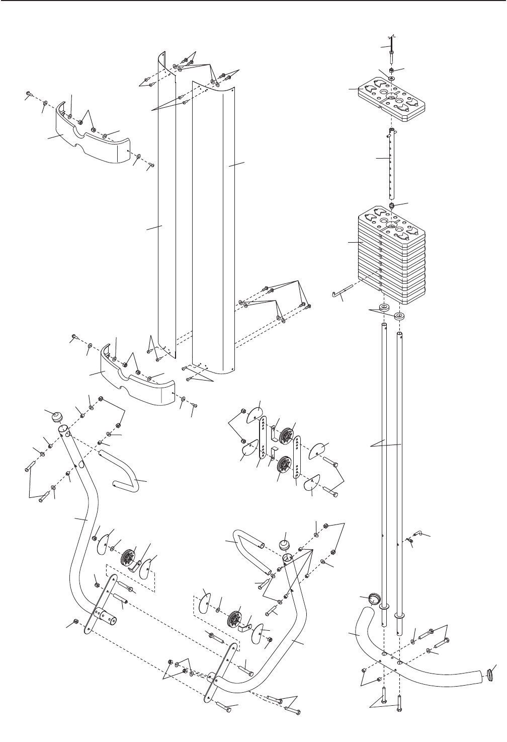
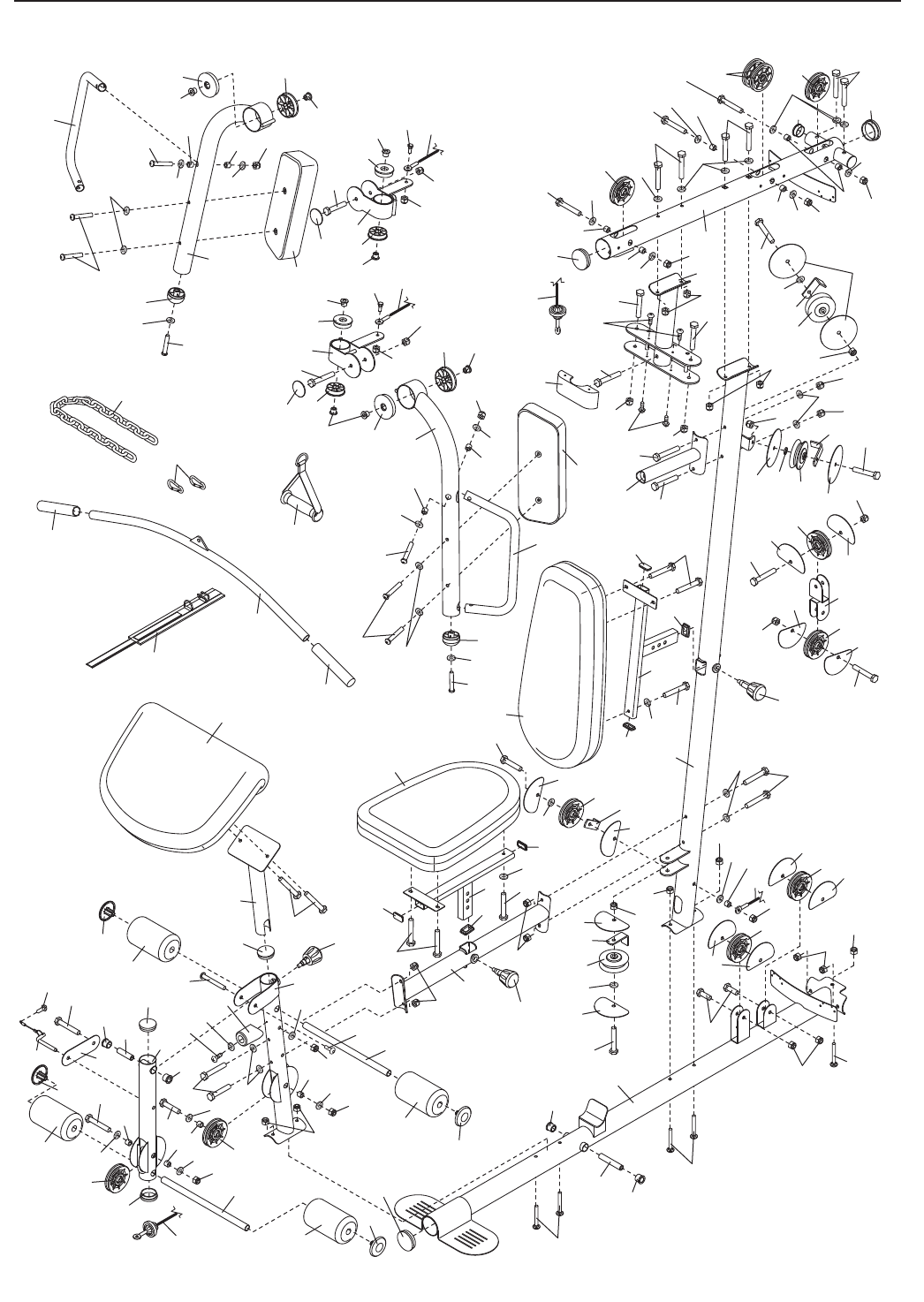
Note: Specifications are subject to change without notice. For information about ordering replacement parts, see
the back cover of this manual. *These parts are not illustrated.
PART LIST—Model No. 831.14622.1 R1209A
Key
No. Qty. Description
Key
No. Qty. Description
Key
No. Qty. Description
11Base
21Upright
31 Stabilizer
41Top Frame
51Butterfly Frame
61Butterfly Frame
Brace
71Backrest Frame
81Seat Frame
91Frame
10 1 Front Leg
11 1 Curl Post
12 1 Leg Lever
13 2 Pad Tube
14 1 Lock Plate
15 1 Left Press Arm
16 1 Right Press Arm
17 2 Press Arm Handle
18 2 Weight Guide
19 10 Weight
20 1 Weight Tube
21 1 Left Shroud
22 1 Right Shroud
23 2 Shroud Cover
24 2 Thin Pulley
25 1 Left Butterfly Arm
26 1 Right Butterfly Arm
27 2 Butterfly Handle
28 1 Left Butterfly Bracket
29 1 Right Butterfly
Bracket
30 1 Butterfly Cover
31 1 Backrest
32 1 Seat
33 1 Curl Pad
34 1 Left Butterfly Pad
35 1 Right Butterfly Pad
36 4 Foam Pad
37 4 Pad Cap
38 5 63.5mm Round Inner
Cap
39 3 50mm Round Inner
Cap
40 2 Press Arm Cap
41 4 40mm x 20mm Inner
Cap
42 2 40mm x 25mm Inner
Cap
43 2 Butterfly Arm Cap
44 2 Bolt Cap
45 4 Butterfly Arm Bushing
46 4 Butterfly Bracket
Bushing
47 3 V-pulley
48 13 90mm Pulley
49 1 Lat Cable
50 1 Butterfly Cable
51 1 Leg Lever Cable
52 1 Seat Adjustment
Knob
53 1 Backrest Adjustment
Knob
54 4 Guard
55 20 Half Guard
56 5 Cable Trap
57 3 Long Cable Trap
58 1 Curl Adjustment Knob
59 2 89.5mm Spacer
60 2 Pulley Plate
61 1 Double “U”-Bracket
62 1 Ankle Strap
63 1 Lat Bar
64 2 Hand Grip
65 1 Handle
66 2 Weight Clip
67 6 19mm Spacer
68 4 25mm Bushing
69 1 56.5mm Spacer
70 1 Weight Pin
71 2 Weight Bumper
72 1 Lock Pin
73 1 Lock
74 8 16mm Bushing
75 1 Leg Lever Bumper
76 1 Weight Tube Cap
77 33 M10 Locknut
78 18 M8 Locknut
79 2 M10 x 60mm Bolt
80 35 M10 Washer
81 2 M10 x 85mm Bolt
82 2 M10 x 75mm Bolt
83 5 M8 x 75mm Carriage
Bolt
84 5 M10 x 80mm Bolt
85 4 M10 x 65mm Bolt
86 4 M10 x 45mm Bolt
87 1 M8 x 69mm Shoulder
Bolt
88 6 M6 x 16mm Screw
89 2 M6 x 32mm Screw
90 2 M8 x 22mm Shoulder
Bolt
91 4 M6 x 60mm Button
Screw
92 2 M10 x 82mm Button
Screw
93 2 M10 x 110mm Bolt
94 4 M6 x 28mm Bolt
95 1 Lock Plate Pin
96 4 M10 x 20mm Button
Screw
97 4 M10 x 50mm Bolt
98 1 M12 Large Washer
99 8 11mm Spacer
100 8 M8 x 80mm Bolt
101 2 M8 x 65mm Bolt
102 13 M4 x 12mm Self-tap-
ping Screw
103 11 M8 Washer
104 9 M4 Washer
105 2 M10 Large Washer
106 6 M10 x 65mm Button
Bolt
107 4 M6 Locknut
108 2 21mm Steel Spacer
109 8 13mm Steel Spacer
110 9 M4 x 16mm Self-tap-
ping Screw
111 1 7mm Spacer
112 1 M12 Nut
113 1 M10 x 70mm Bolt
114 14 M6 Washer
115 1 M10 x 120mm Bolt
116 1 M10 x 61mm Bolt Set
117 1 Chain
118 1 M10 x 75mm Button
Screw
119 2 38mm Round Inner
Cap
*–User’s Manual
*–Exercise Guide
*–Assembly Tool
*–Grease Packet
33
3
15
16
17
17
18
19
19
20
21
22
23
23
38
38
40
40
48
48
48
48
49
55
55
55
55
55
55
55
55
56
56
56
56
59
60
60
108
70 71
72
73
76
77
77
77
106
77
80
80
80
80
80
80
80
80
80
93
93
77
81
97
94
94
102
102
94
94
102
98
97
97
77
77
85
80
110
110
1
77
99
99
99
99
99
102
114
114
114
114
107
114
114
114
114
107
110
104
104
80
80
112
106
106
96
EXPLODED DRAWING A—Model No. 831.14622.1 R1209A
34
1
2
4
5
6
7
8
9
10
11
12
13
13
14
25
27
28
30
31
32
33
34
36
36
36
36
37
37
37
37
38
39
39
38
41
41
41
41
42
43
44
46
46
45
45
47
47
47
48
24 48
48
48
48
48
48
48
48
49
50
51
51
52
58
53
54
54
54
55
55
55
55
55
55
55
55
55
55
55
56
57
57
57
59
61
62
63
64
64 65
66
109
109
68
68 109
68
68
67
67
67
67 67
74
74
75
77
77
78
77
78
77
77
78
78
78
78
78
78
77
74
77
77
77
77
78
77
77
78
116
7
77
77
80
103 103 80
80
80
80
80
103
85
80
80
103
104
83
83
84
84
84
100
100
79
79
100
100
118
86
86
100
113
86
115
101
85 80
103
87
88
88
89
88
89
84 84
77
90
106
92
116
110
95
102
91
102
102
69
111
80
114
114
109 109
82
29
44
46
46
50
78
74
77
90
82
26
27
35
43
45 45
74
74
77
8080
106
92
91
109 109
74
114
105
114 105
78
103
78
80
80
80
80
80
42
80
77
38
39
83
77
117
8096
119
EXPLODED DRAWING B—Model No. 831.14622.1 R1209A
35

Part No. 250527 R1209A Printed in China © 2009 ICON IP, Inc.
1-800-361-6665 (
(U.S.A. and Canada)
www.sears.com www.sears.ca
G
A
(U.S.A. and Canada)
www.sears.ca
O
A
1
S
Your Home
For repair—in your home—of all major brand appliances, lawn and garden equipment,
or heating and cooling systems, no matter who made it, no matter who sold it!
For the replacement parts, accessories, and user’s manuals that you need to do-it-yourself.
For Sears professional installation of home appliances
and items like garage door openers and water heaters.
1-800-4-MY-HOME® (1-800-469-4663)
Call anytime, day or night (U.S.A. and Canada)
www.sears.com www.sears.ca
Our Home
For repair of carry-in items like vacuums, lawn equipment,
and electronics, call or go on-line for the location of your nearest
Sears Parts & Repair Center.
1-800-488-1222 Call anytime, day or night (U.S.A. only)
www.sears.com
To purchase a protection agreement (U.S.A.)
or maintenance agreement (Canada) on a product serviced by Sears:
1-800-827-6655 (U.S.A.) 1-800-361-6665 (Canada)
Para pedir servicio de reparación a domicilio, y para ordenar piezas:
1-888-SU-HOGAR® (1-888-784-6427)
Get it fixed, at your home or ours!
® Registered Trademark / TM Trademark / SM Service Mark of Sears Brands, LLC
® Marca Registrada / TM Marca de Fábrica / SM Marca de Servicio de Sears Brands, LLC
90 DAY FULL WARRANTY
If this Sears WEIGHT SYSTEM EXERCISER fails due to a defect in material or workmanship within 90
days of the date of purchase, call 1-800-4-MY-HOME®(1-800-469-4663) to arrange for free repair (or
replacement if repair proves impossible).
This warranty does not apply when the WEIGHT SYSTEM EXERCISER is used commercially or for
rental purposes. This warranty gives you specific legal rights, and you may also have other rights which
vary from state to state.
Sears, Roebuck and Co., Hoffman Estates, IL 60179
