Weider Pro 4950 14623 Owners Manual
831146230 831146230 WEIDER WEIDER PRO 4950 - Manuals and Guides L0609451 View the owners manual for your WEIDER WEIDER PRO 4950 #831146230. Home:Fitness Equipment Parts:Weider Parts:Weider WEIDER PRO 4950 Manual
WEIDER Weight System Manual L0609451 WEIDER Weight System Owner's Manual, WEIDER Weight System installation guides
2014-08-26
: Weider Weider-Pro-4950-14623-Owners-Manual weider-pro-4950-14623-owners-manual weider pdf
Open the PDF directly: View PDF ![]() .
.
Page Count: 44
R PRO
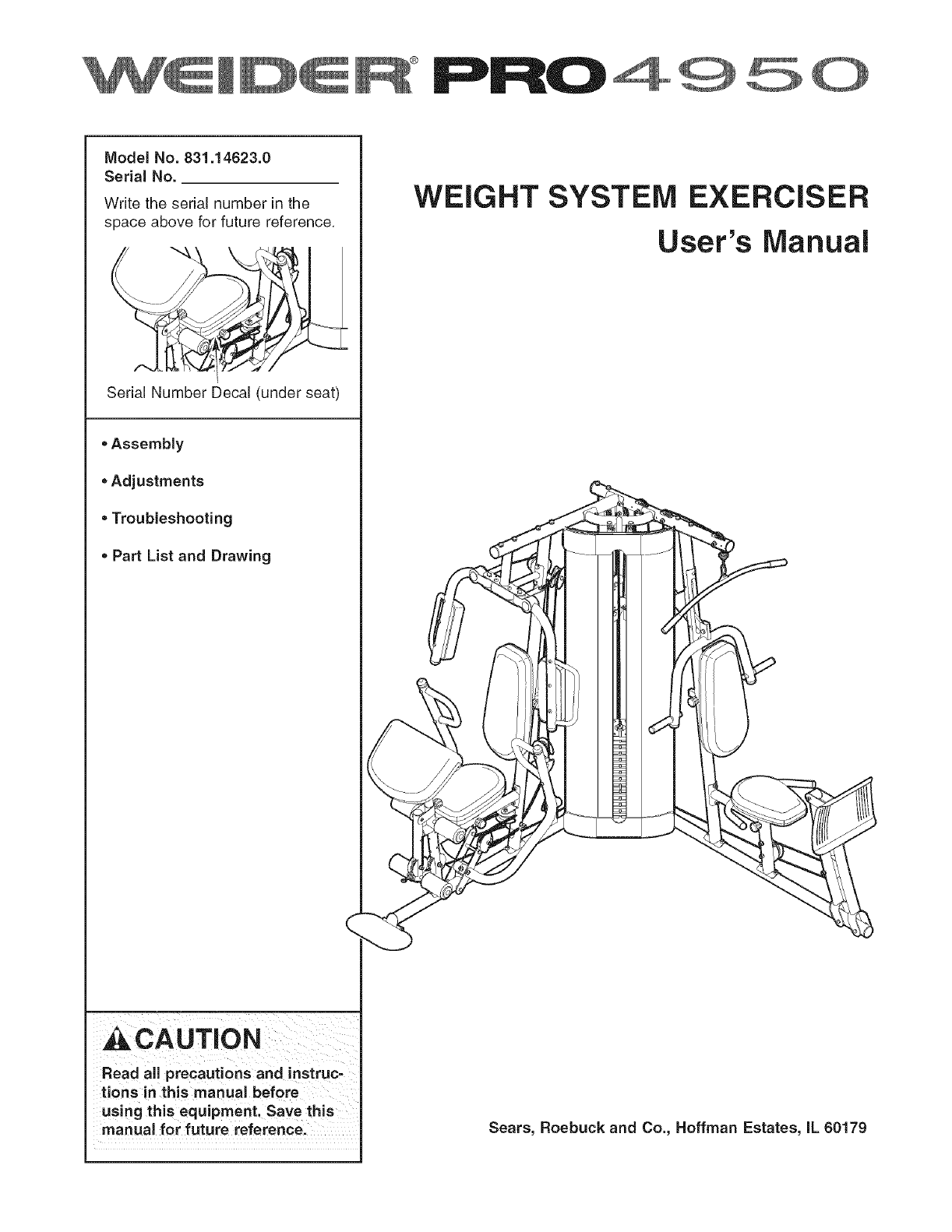
Model No. 831.14623.0
Serial No.
Write the serial number in the
space above for future reference.
Serial Number Decal (under seat)
, Assembly
, Adjustments
,Troubleshooting
, Part List and Drawing
WEIGHT SYSTEM EXERCISER
User's Manual
_CAUTION
Read all precautions and instruc-
tions in this manual before
using this equipment. Save this
manual for future reference. Sears, Roebuck and Co., Hoffman Estates, IL 60179
TABLE OF CONTENTS
iMPORTANT PRECAUTIONS ................................................................ 3
BEFORE YOU BEGIN ...................................................................... 4
PART iDENTiFiCATiON CHART .............................................................. 5
ASSEMBLY .............................................................................. 7
ADJUSTMENTS .......................................................................... 28
WEIGHT RESISTANCE CHART .............................................................. 31
CABLE DIAGRAM ......................................................................... 32
MAINTENANCE .......................................................................... 34
EXERCISE GUiDELiNES ................................................................... 35
PART LiST .............................................................................. 39
EXPLODED DRAWING .................................................................... 41
ORDERING REPLACEMENT PARTS .................................................. Back Cover
90 DAY FULL WARRANTY .......................................................... Back Cover
iMPORTANT PRECAUTIONS
_WARNING: To reduce the risk of serious injury, read the following important precautions
before using the weight system.
1. Read all instructions in this manual and all
warnings on the weight system before using
the weight system. Use the weight system
only as described in this manual.
2. it is the responsibUity of the owner to ensure
that all users of the weight system are ade-
12. Always make sure that the weight pin is
inserted fully into the weight stack before
exercising.
13. if you feel pain or dizziness at any time while
exercising, stop immediately and begin cool-
ing down.
quately informed of all precautions.
14. Always secure the weight stack with the lock
3. The weight system is intended for home use pin and lock after exercising to prevent
only. Do not use the weight system in any unauthorized use of the weight system (see
commercial, rental, or institutional setting. LOCKING THE WEIGHT STACK on page 29).
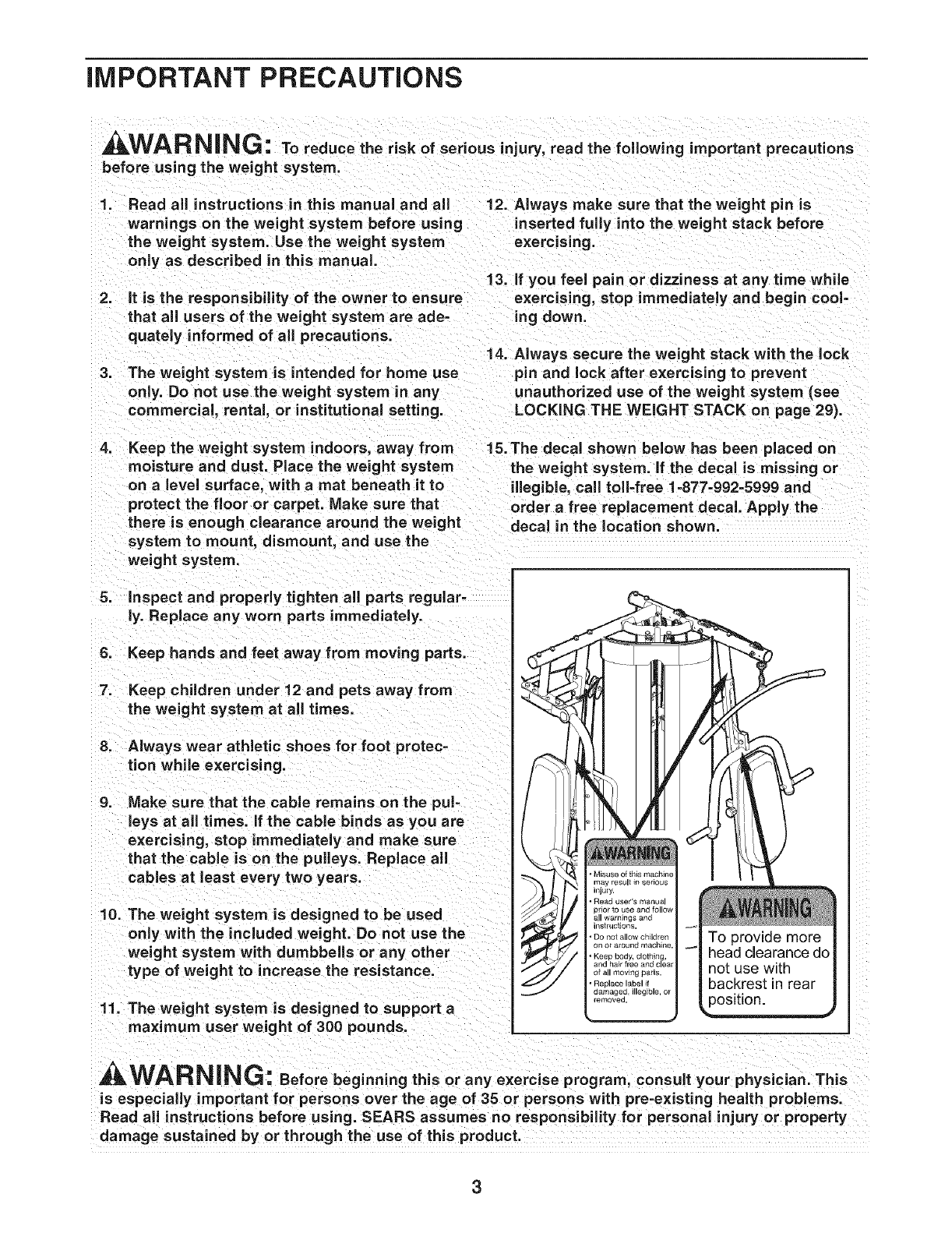
4. Keep the weight system indoors, away from 15. The decal shown below has been placed on
moisture and dust. Place the weight system
on alevel surface, with amat beneath it to
protect the floor or carpet. Make sure that
there is enough clearance around the weight
system to mount, dismount, and use the
weight system.
the weight system, if the decal is missing or
illegible, call toll4ree 1=877-992-5999 and
order a free replacement decal. Apply the
decal in the location shown.
5. Inspect and properly tighten all parts regular-
ly. Replace any worn parts immediately.
6. Keep hands and feet away from moving parts.
7. Keep chUdren under 12 and pets away from
the weight system at all times.
8. Always wear athletic shoes for foot protec-
tion while exercising.
.Make sure that the cable remains on the pul-
leys at all times, if the cable binds as you are
exercising, stop immediately and make sure
that the cable is on the pulleys. Replace all
cables at least every two years.
10. The weight system is designed to be used
only with the included weight. Do not use the
weight system with dumbbells or any other
type of weight to increase the resistance.
11. The weight system is designed to support a
maxi mum user weight of 300 pounds.
A
n jury.
• Read user's manua
)nor to use and follo_
all wammqs ano
nstruct_ons
• DO not allow ch_ldrer
on or arouna macnlne
° }£eep body, ClOtlllng
and hair free and clear
of all moving parts.
• Replace label il
damaged, illegible, o_
emovea
|
-'| To provide more
_| head clearance do
| not use with
| backrest in rear
Lposition.
A WAR NiNG: Beforebeginningthisoranyexerciseprogram,consultyourphysic ian.This
is especially important for persons over the age of 35 or persons with pre-existing health problems.
Read all instructions before using. SEARS assumes no responsibility for personal injury or property
damage sustained by or through the use of this product.
3
BEFORE YOU BEGIN
Thank you for selecting the versatile WELDER TM PRO
4950 weight system. The weight system offers a selec-
tion of weight stations designed to develop every major
muscle group of the body. Whether your goal is to tone
your body, build dramatic muscle size and strength, or
improve your cardiovascular system, the weight system
will help you to achieve the specific results you want.
For your benefit, read this manual carefully before
using the weight system, if you have questions after
reading this manual, please see the front cover of this
manual. To help us assist you, note the product model
number and serial number before contacting us. The
model number is 831.14623.0. The serial number can
be found on a decal attached to the weight system
(see the front cover of this manual).
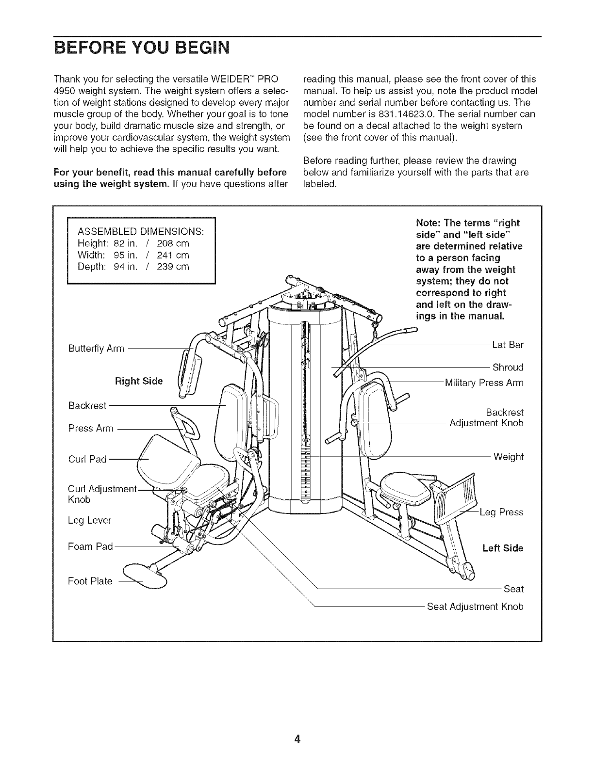
Before reading further, please review the drawing
below and familiarize yourself with the parts that are
labeled.
ASSEMBLED DIMENSIONS:
Height: 82 in. /208 cm
Width: 95 in. /241 cm
Depth: 94 in. /239cm
Butterfly Arm
Right Side
Backrest
Press Arm
Curl
Curl Adjustment
Knob
Leg Level
Foam Pad
Note: The terms "right
side" and "left side"
are determined relative
to a person facing
away from the weight
system; they do not
correspond to right
and left on the draw=
ings in the manual.
Lat Bar
Shroud
Military Press Arm
Backrest
Adjustment Knob
)
-Leg Press
Left Side
Foot Plate Seat
Seat Adjustment Knob
4
PART IDENTiFiCATiON CHART--Model No.831.14623.0 RO606A
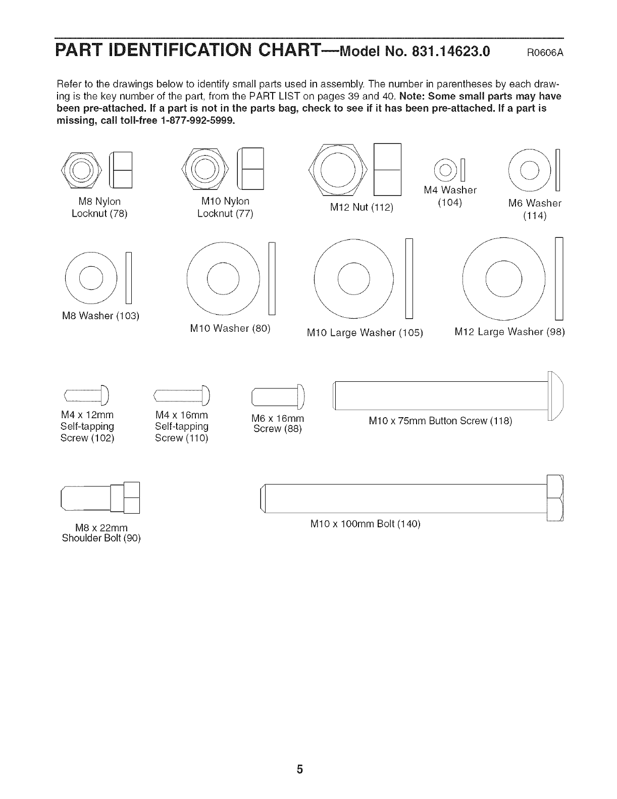
Refer to the drawings below to identify small parts used in assembly. The number in parentheses by each draw-
ing is the key number of the part, from the PART LIST on pages 39 and 40. Note: Some small parts may have
been pre-attached, if apart is not in the parts bag, check to see if it has been pre-attached, if apart is
missing, call toll-free 1-877-992-5999.
M8 Nylon
Locknut (78)
MIO Nylon
Locknut (77) M12 Nut (112)
M4 Washer
(104) M6 Washer
(114)
M8 Washer (103) [
MIO Washer (80) MIO Large Washer (105)
1
M12 Large Washer (98)
M4 x 12mm M4 x 16mm
Self-tapping Self-tapping
Screw (102) Screw (110)
D
M6 x 16mm
Screw (88) MIO x 75mm Button Screw (118)
M8 x 22mm
Shoulder Bolt (90)
MIO x lOOmm Bolt (140)
5
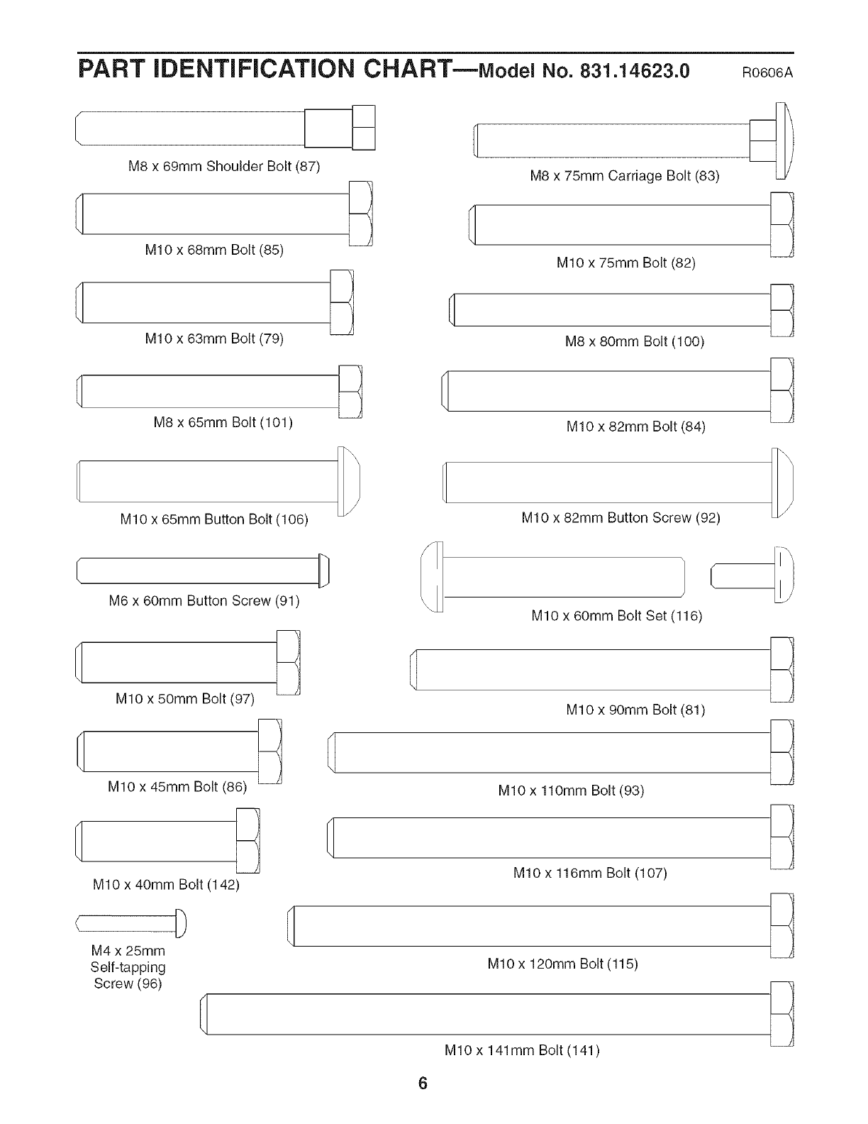
PART iDENTiFiCATiON CHART--Model No.831.14623.0
M8 x 69mm Shoulder Bolt (87)
MIO x 68mm Bolt (85)
M10 x 63mm Bolt (79)
M8 x 65mm Bolt (101)
MIO x 65mm Button Bolt (106)
M8 x 75mm Carriage Bolt (83)
MIO x 75mm Bolt (82)
M8 x 80ram Bolt (100)
MIO x 82mm Bolt (84)
M10 x 82mm Button Screw (92)
RO606A
M6 x 60mm Button Screw (91)
MIO x 50mm Bolt (97)
MIO x 45mm Bolt (86)
MIO x 40mm Bolt (142)
D
M4 x 25mm
Self-tapping
Screw (96)
MIO x 60mm Bolt Set (116)
MIO x 90mm Bolt (81)
MIO x 110mm Bolt (93)
MIO x 116mm Bolt (107)
MIO x 120mm Bolt (115)
MIO x 141mm Bolt (141)
ASSEMBLY
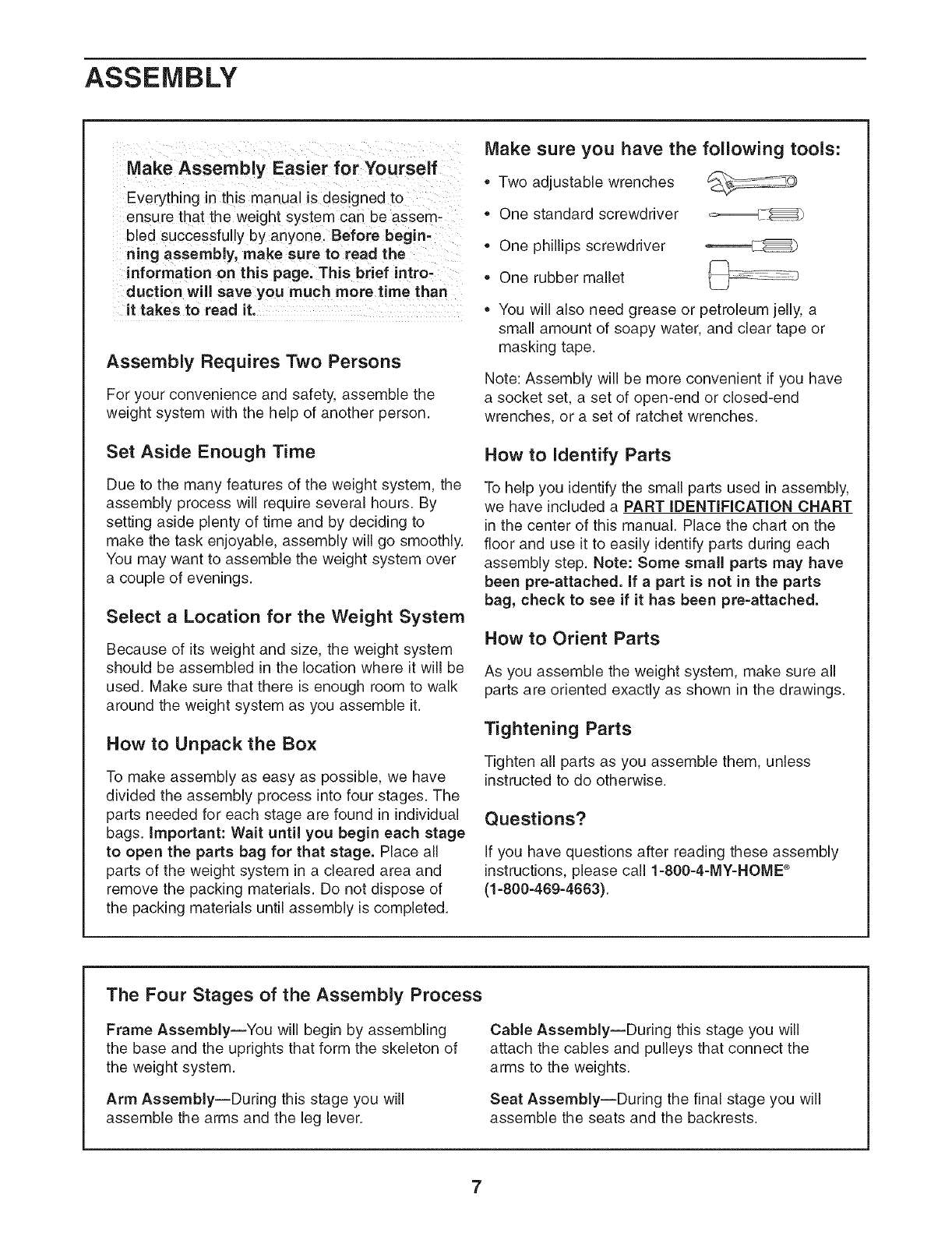
Make Assembly Easier for Yourself
Everything in this manual is designed to
ensu re that the weight system can be assem-
bled successfully by anyone. Before begin=
ning assembly, make sure to read the
information on this page. This brief intro-
duction will save you much more time than
it takes to read it.
Assembly Requires Two Persons
For your convenience and safety, assemble the
weight system with the help of another person.
Set Aside Enough Time
Due to the many features of the weight system, the
assembly process will require several hours. By
setting aside plenty of time and by deciding to
make the task enjoyable, assembly will go smoothly.
You may want to assemble the weight system over
a couple of evenings.
Select aLocation for the Weight System
Because of its weight and size, the weight system
should be assembled in the location where it will be
used. Make sure that there is enough room to walk
around the weight system as you assemble it.
How to Unpack the Box
To make assembly as easy as possible, we have
divided the assembly process into four stages. The
parts needed for each stage are found in individual
bags. Important: Wait until you begin each stage
to open the parts bag for that stage. Place all
parts of the weight system in a cleared area and
remove the packing materials. Do not dispose of
the packing materials until assembly is completed.
Make sure you have the following tools:
* Two adjustable wrenches
One standard screwdriver _-_[ I_
, One phillips screwdriver
, One rubber mallet
, You will also need grease or petroleum jelly, a
small amount of soapy water, and clear tape or
masking tape.
Note: Assembly will be more convenient if you have
a socket set, a set of open-end or closed-end
wrenches, or a set of ratchet wrenches.
How to Identify Parts
To help you identify the small parts used in assembly,
we have included aPART iDENTiFiCATiON CHART
in the center of this manual. Place the chart on the
floor and use it to easily identify parts during each
assembly step. Note: Some small parts may have
been pre-attached, if apart is not in the parts
bag, check to see if it has been pre-attached.
How to Orient Parts
As you assemble the weight system, make sure all
parts are oriented exactly as shown in the drawings.
Tightening Parts
Tighten all parts as you assemble them, unless
instructed to do otherwise.
Questions?
If you have questions after reading these assembly
instructions, please call 1-800-4-MY=HOME ®
(1-800-469-4663).
The Four Stages of the Assembly Process
Frame Assembly--You will begin by assembling
the base and the uprights that form the skeleton of
the weight system.
Arm Assembly--During this stage you will
assemble the arms and the leg lever.
Cable Assembly--During this stage you will
attach the cables and pulleys that connect the
arms to the weights.
Seat Assembly--During the final stage you will
assemble the seats and the backrests.
7
Frame Assembly
Before beginning assembly, make sure
YOu understand th e information in the
box on page 7, See the PART IDENTIFI,
CATIONCNARTSOnpages5and6for
help identifying small parts.
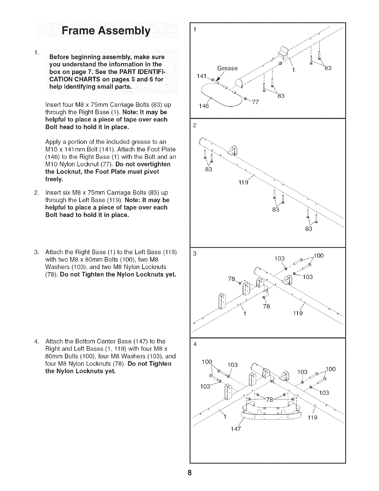
Insert four M8 x 75mm Carriage Bolts (83) up
through the Right Base (1). Note: It may be
helpful to place a piece of tape over each
Bolt head to hold it in place.
Apply a portion of the included grease to an
MIO x 141mm Bolt (141). Attach the Foot Plate
(146) to the Right Base (1) with the Bolt and an
MIO Nylon Locknut (77). Do not overtighten
the Locknut, the Foot Plate must pivot
freely.
insert six M8 x 75mm Carriage Bolts (83) up
through the Left Base (119). Note: It may be
helpful to place apiece of tape over each
Bolt head to hold it in place.
Attach the Right Base (1) to the Left Base (119)
with two M8 x 80mm Bolts (100), two M8
Washers (103), and two M8 Nylon Locknuts
(78). Do not Tighten the Nylon Locknuts yet.
Attach the Bottom Center Base (147) to the
Right and Left Bases (1,119) with four M8 x
80mm Bolts (100), four M8 Washers (103), and
four M8 Nylon Locknuts (78). Do not Tighten
the Nylon Locknuts yet.
146
2
83
Grease
83
83
83
>
78
1 119
1O0 103
103
147
O0
119
8
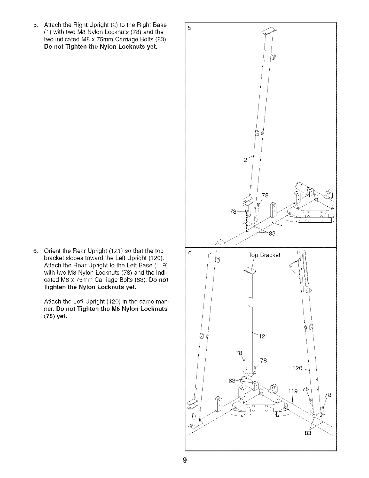
5. 5
Attach the Right Upright (2) to the Right Base
(1) with two M8 Nylon Locknuts (78) and the
two indicated M8 x 75mm Carriage Bolts (83).
Do not Tighten the Nylon Locknuts yet.
Orient the Rear Upright (121) so that the top
bracket slopes toward the Left Upright (120).
Attach the Rear Upright to the Left Base (119)
with two M8 Nylon Locknuts (78) and the indi-
cated M8 x 75mm Carriage Bolts (83). Do not
Tighten the Nylon Locknuts yet.
Attach the Left Upright (120) in the same man-
ner. Do not Tighten the M8 Nylon Locknuts
(78) yet.
78
Top Bracket
I
119
83
9
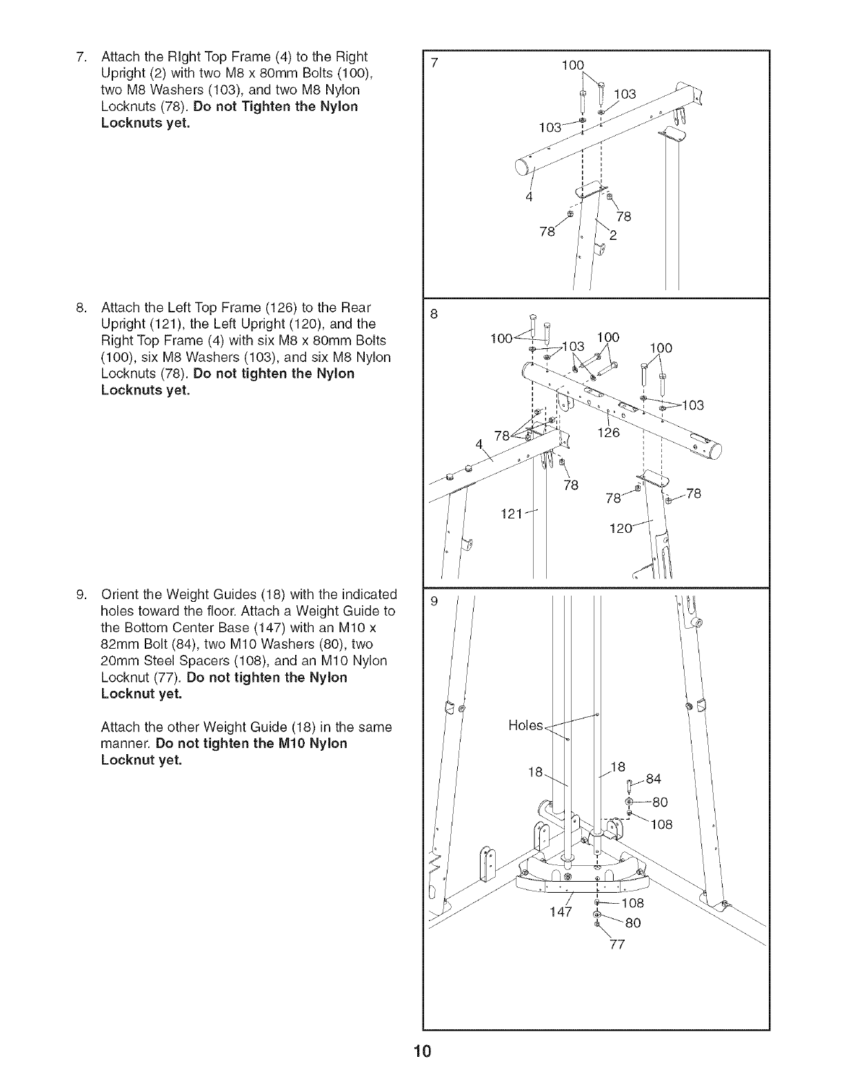
Attach the Right Top Frame (4) to the Right
Upright (2) with two M8 x 80mm Bolts (100),
two M8 Washers (103), and two M8 Nylon
Locknuts (78). Do not Tighten the Nylon
Locknuts yet.
Attach the Left Top Frame (126) to the Rear
Upright (121), the Left Upright (120), and the
Right Top Frame (4) with six M8 x 80mm Bolts
(100), six M8 Washers (103), and six M8 Nylon
Locknuts (78). Do not tighten the Nylon
Locknuts yet.
Orient the Weight Guides (18) with the indicated
holes toward the floor. Attach a Weight Guide to
the Bottom Center Base (147) with an MIO x
82mm Bolt (84), two MIO Washers (80), two
20mm Steel Spacers (108), and an MIO Nylon
Locknut (77). Do not tighten the Nylon
Locknut yet.
Attach the other Weight Guide (18) in the same
manner. Do not tighten the MIO Nylon
Locknut yet.
lO0
103
78
1O0 lO0
126
78
121 1
Holes_
10
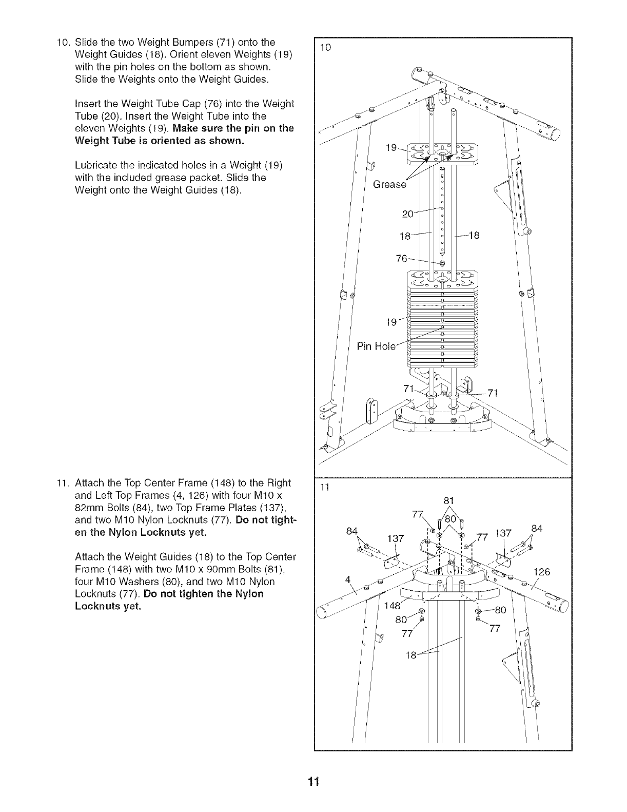
10. Slide the two Weight Bumpers (71) onto the
Weight Guides (18). Orient eleven Weights (19)
with the pin holes on the bottom as shown.
Slide the Weights onto the Weight Guides.
Insert the Weight Tube Cap (76) into the Weight
Tube (20). Insert the Weight Tube into the
eleven Weights (19). Make sure the pin on the
Weight Tube is oriented as shown.
Lubricate the indicated holes in a Weight (19)
with the included grease packet. Slide the
Weight onto the Weight Guides (18).
11. Attach the Top Center Frame (148) to the Right
and Left Top Frames (4, 126) with four M10 x
82mm Bolts (84), two Top Frame Plates (137),
and two M10 Nylon Locknuts (77). Do not tight-
en the Nylon Locknuts yet.
Attach the Weight Guides (18) to the Top Center
Frame (148) with two M10 x 90mm Bolts (81),
four M10 Washers (80), and two M10 Nylon
Locknuts (77). Do not tighten the Nylon
Locknuts yet.
10
11
84
81
7\
77
126
77
11
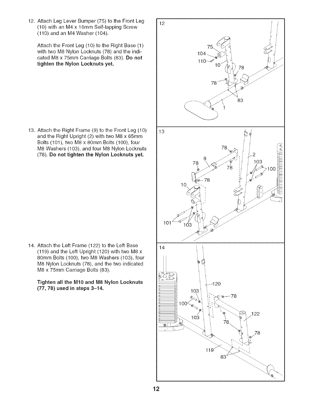
12. Attach Leg Lever Bumper (75) to the Front Leg
(10) with an M4 x 16mm Self-tapping Screw
(110) and an M4 Washer (104).
Attach the Front Leg (10) to the Right Base (1)
with two M8 Nylon Locknuts (78) and the indi-
cated M8 x 75mm Carriage Bolts (83). Do not
tighten the Nylon Locknuts yet.
13. Attach the Right Frame (9) to the Front Leg (10)
and the Right Upright (2) with two M8 x 65mm
Bolts (101), two M8 x 80mm Bolts (100), four
M8 Washers (10% and four M8 Nylon Locknuts
(78). Do not tighten the Nylon Locknuts yet.
14. Attach the Left Frame (122) to the Left Base
(119) and the Left Upright (120) with two M8 x
80mm Bolts (100), two M8 Washers (10% four
M8 Nylon Locknuts (78), and the two indicated
M8 x 75mm Carriage Bolts (83).
Tighten all the M10 and M8 Nylon Locknuts
(77, 78) used in steps 3-14.
12
13
101
14
78
83
78
78
78
2
103
10
103
103
12
Arm Assem bly
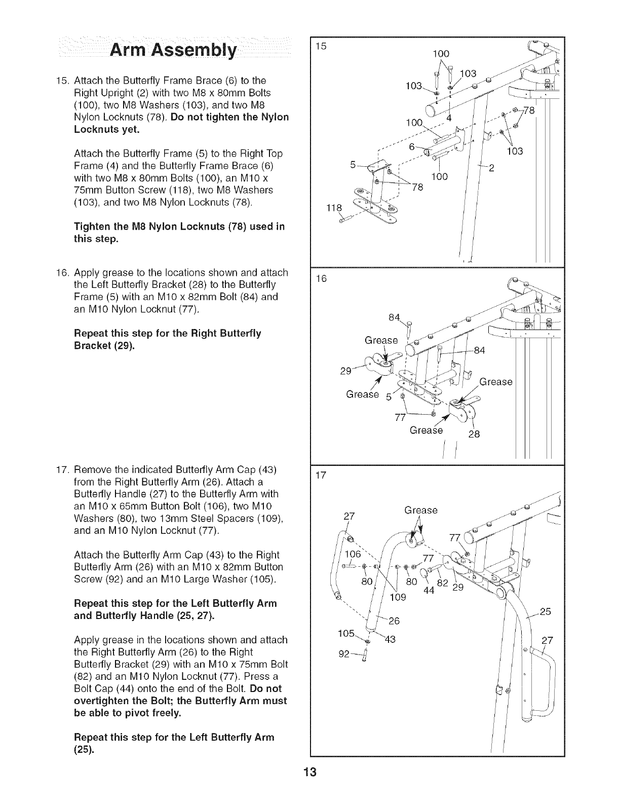
15. Attach the Butterfly Frame Brace (6) to the
Right Upright (2) with two M8 x 80mm Bolts
(100), two M8 Washers (103), and two M8
Nylon Locknuts (78). Do not tighten the Nylon
Locknuts yet.
Attach the Butterfly Frame (5) to the Right Top
Frame (4) and the Butterfly Frame Brace (6)
with two M8 x 80mm Bolts (100), an M10 x
75mm Button Screw (118), two M8 Washers
(103), and two M8 Nylon Locknuts (78).
Tighten the M8 Nylon Locknuts (78) used in
this step.
16. Apply grease to the locations shown and attach
the Left Butterfly Bracket (28) to the Butterfly
Frame (5) with an M10 x 82mm Bolt (84) and
an M10 Nylon Locknut (77).
Repeat this step for the Right Butterfly
Bracket (29).
17. Remove the indicated Butterfly Arm Cap (43)
from the Right Butterfly Arm (26). Attach a
Butterfly Handle (27) to the Butterfly Arm with
an M10 x 65mm Button Bolt (106), two M10
Washers (80), two 13mm Steel Spacers (109),
and an M10 Nylon Locknut (77).
Attach the Butterfly Arm Cap (43) to the Right
Butterfly Arm (26) with an M10 x 82mm Button
Screw (92) and an M10 Large Washer (105).
Repeat this step for the Left Butterfly Arm
and Butterfly Handle (25, 27).
Apply grease in the locations shown and attach
the Right Butterfly Arm (26) to the Right
Butterfly Bracket (29) with an M10 x 75mm Bolt
(82) and an M10 Nylon Locknut (77). Press a
Bolt Cap (44) onto the end of the Bolt. Do not
overtighten the Bolt; the Butterfly Arm must
be able to pivot freely.
Repeat this step for the Left Butterfly Arm
(25).
15
16
17
100
103
-2
/
Grease
Grease 5"
Grease 28
27 Grease
77
\\
109
"26
44
/
/
/
/
/
13
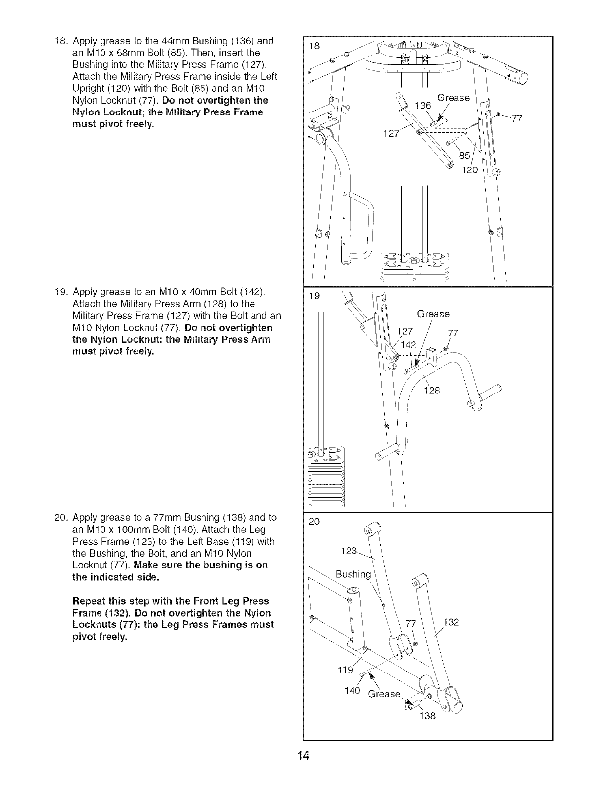
18. Apply grease to the 44mm Bushing (136) and
an M10 x 68mm Bolt (85). Then, insert the
Bushing into the Military Press Frame (127).
Attach the Military Press Frame inside the Left
Upright (120) with the Bolt (85) and an M10
Nylon Locknut (77). Do not overtighten the
Nylon Locknut; the Military Press Frame
must pivot freely.
19. Apply grease to an M10 x 40mm Bolt (142).
Attach the Military Press Arm (128) to the
Military Press Frame (127) with the Bolt and an
M10 Nylon Locknut (77). Do not overtighten
the Nylon Locknut; the Military Press Arm
must pivot freely.
20. Apply grease to a 77mm Bushing (138) and to
an M10 x 100mm Bolt (140). Attach the Leg
Press Frame (123) to the Left Base (119) with
the Bushing, the Bolt, and an M10 Nylon
Locknut (77). Make sure the bushing is on
the indicated side.
Repeat this step with the Front Leg Press
Frame (132). Do not overtighten the Nylon
Locknuts (77); the Leg Press Frames must
pivot freely.
18
19
20
14O
• o
Grease
77
128
132
138
14
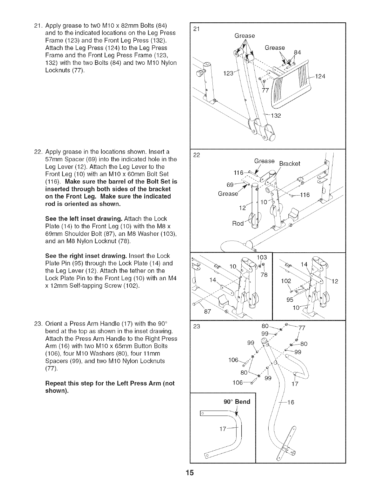
21. Apply grease to twO M10 x 82mm Bolts (84)
and to the indicated locations on the Leg Press
Frame (123) and the Front Leg Press (132).
Attach the Leg Press (124) to the Leg Press
Frame and the Front Leg Press Frame (123,
132) with the two Bolts (84) and two M10 Nylon
Locknuts (77).
21 Grease
I Grease 84
124
22. Apply grease in the locations shown. Insert a
57mm Spacer (69) into the indicated hole in the
Leg Lever (12). Attach the Leg Lever to the
Front Leg (10) with an M10 x 60mm Bolt Set
(116). Make sure the barrel of the Bolt Set is
inserted through both sides of the bracket
on the Front Leg. Make sure the indicated
rod is oriented as shown.
See the left inset drawing. Attach the Lock
Plate (14) to the Front Leg (10) with the M8 x
69mm Shoulder Bolt (87), an M8 Washer (103),
and an M8 Nylon Locknut (78).
See the right inset drawing. Insert the Lock
Plate Pin (95) through the Lock Plate (14) and
the Leg Lever (12). Attach the tether on the
Lock Plate Pin to the Front Leg (10) with an M4
x 12mm Self-tapping Screw (102).
23. Orient a Press Arm Handle (17) with the 90°
bend at the top as shown in the inset drawing.
Attach the Press Arm Handle to the Right Press
Arm (16) with two M10 x 65mm Button Bolts
(106), four M10 Washers (80), four 11mm
Spacers (99), and two M10 Nylon Locknuts
(77).
Repeat this step for the Left Press Arm (not
shown).
22
Grease Bracket ._
69 ',_:_ - _ I
Grease _ t _116 ju
78 102 "_"
951 O_
23 80 ----,__,,_----_-77
99----d" /
99
106--d,_/ )) 17
2
)
"12
15
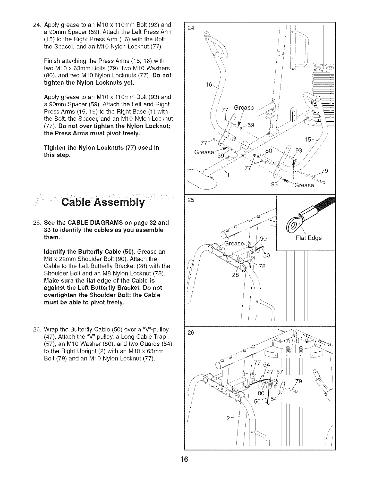
24. Apply grease to an M10 x 110mm Bolt (93) and
a 90mm Spacer (59). Attach the Left Press Arm
(15) to the Right Press Arm (16) with the Bolt,
the Spacer, and an M10 Nylon Locknut (77).
Finish attaching the Press Arms (15, 16) with
two M10 x 63mm Bolts (79), two M10 Washers
(80), and two M10 Nylon Locknuts (77). Do not
tighten the Nylon Locknuts yet.
Apply grease to an M10 x 110mm Bolt (93) and
a 90mm Spacer (59). Attach the Left and Right
Press Arms (15, 16) to the Right Base (1) with
the Bolt, the Spacer, and an M10 Nylon Locknut
(77). Do not over tighten the Nylon Locknut;
the Press Arms must pivot freely.
Tighten the Nylon Locknuts (77) used in
this step.
24
J!
JJ
16_ /
Ji
Ji i i II
i _ i JJ
i i° ff
t
Cable Assembly
25. See the CABLE DIAGRAMS on page 32 and
33 to identify the cables as you assemble
them.
identify the Butterfly Cable (50). Grease an
M8 x 22mm Shoulder Bolt (90). Attach the
Cable to the Left Butterfly Bracket (28) with the
Shoulder Bolt and an M8 Nylon Locknut (78).
Make sure the fiat edge of the Cable is
against the Left Butterfly Bracket. Do not
overtighten the Shoulder Bolt; the Cable
must be able to pivot freely.
26. Wrap the Butterfly Cable (50) over a "V'-pulley
(47). Attach the "V'-pulley, a Long Cable Trap
(57), an M10 Washer (80), and two Guards (54)
to the Right Upright (2) with an M10 x 63mm
Bolt (79) and an M10 Nylon Locknut (77).
25 S
f.__.__ Flat Edge
_/ 28 "
/475'1 I _ ',
50% 54
16
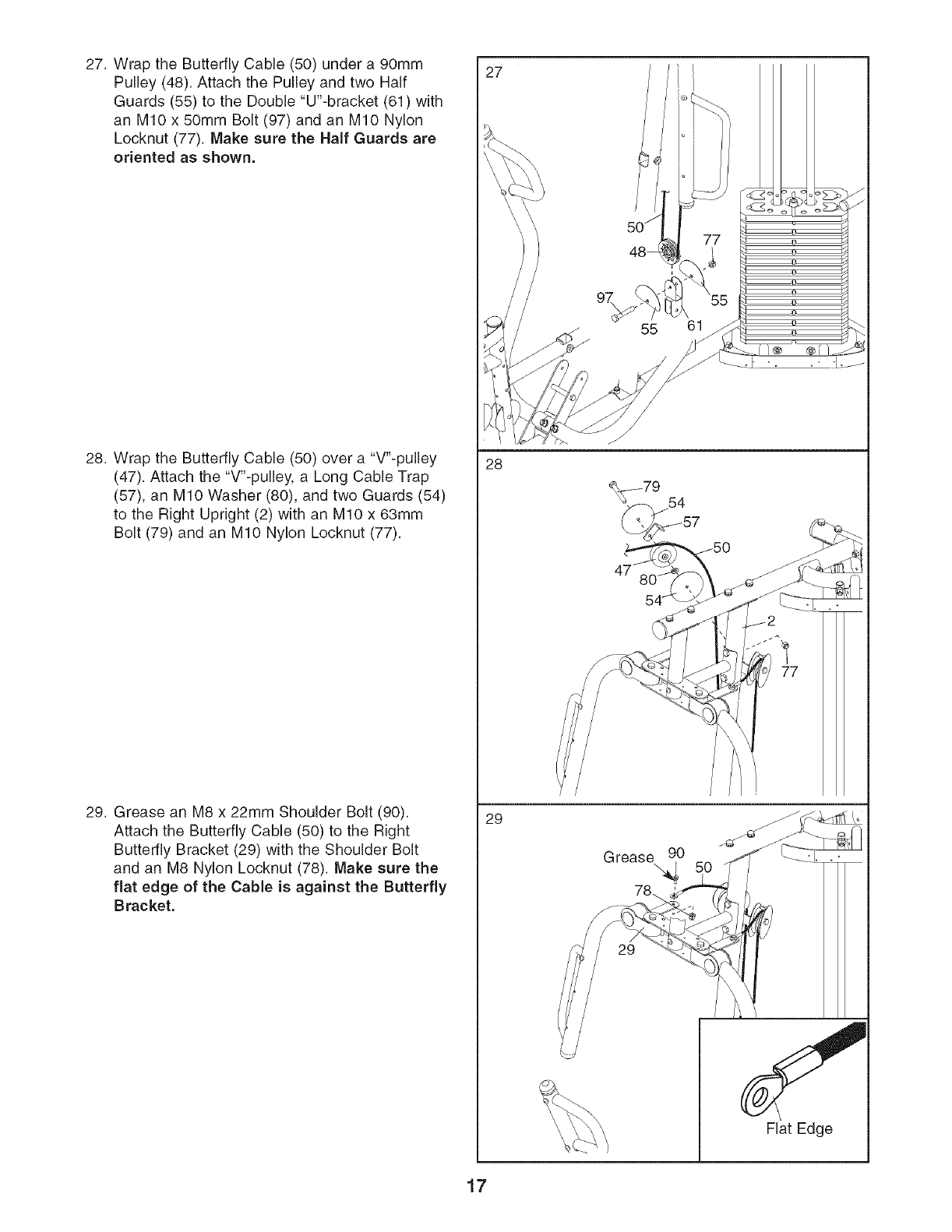
27. Wrap the Butterfly Cable (50) under a 90mm
Pulley (48). Attach the Pulley and two Half
Guards (55) to the Double "U'-bracket (61) with
an M10 x 50mm Bolt (97) and an M10 Nylon
Locknut (77). Make sure the Half Guards are
oriented as shown.
28. Wrap the Butterfly Cable (50) over a "V'-pulley
(47). Attach the "V'-pulley, a Long Cable Trap
(57), an M10 Washer (80), and two Guards (54)
to the Right Upright (2) with an M10 x 63ram
Bolt (79) and an M10 Nylon Locknut (77).
29. Grease an M8 x 22mm Shoulder Bolt (90).
Attach the Butterfly Cable (50) to the Right
Butterfly Bracket (29) with the Shoulder Bolt
and an M8 Nylon Locknut (78). Make sure the
flat edge of the Cable is against the Butterfly
Bracket.
27
28
29
Grease 90
78_.
Flat Edge
17
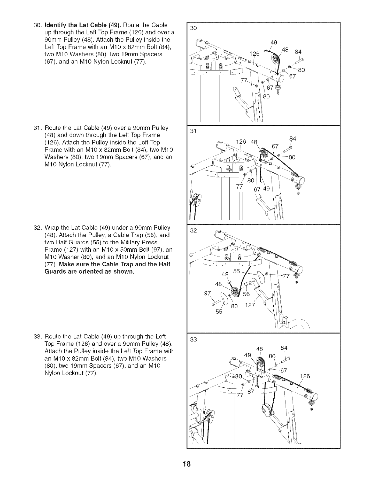
30. Identify the Lat Cable (49). Route the Cable
up through the Left Top Frame (126) and over a
90ram Pulley (48). Attach the Pulley inside the
Left Top Frame with an MIO x 82ram Bolt (84),
two MIO Washers (80), two 19ram Spacers
(67), and an MIO Nylon Locknut (77).
31. Route the Lat Cable (49) over a 90mm Pulley
(48) and down through the Left Top Frame
(126). Attach the Pulley inside the Left Top
Frame with an MIO x 82mm Bolt (84), two MIO
Washers (80), two 19mm Spacers (67), and an
MIO Nylon Locknut (77).
32. Wrap the Lat Cable (49) under a 90mm Pulley
(48). Attach the Pulley, a Cable Trap (56), and
two Half Guards (55) to the Military Press
Frame (127) with an MIO x 50mm Bolt (97), an
MIO Washer (80), and an MIO Nylon Locknut
(77). Make sure the Cable Trap and the Half
Guards are oriented as shown.
33. Route the Lat Cable (49) up through the Left
Top Frame (126) and over a 90mm Pulley (48).
Attach the Pulley inside the Left Top Frame with
an MIO x 82mm Bolt (84), two MIO Washers
(80), two 19mm Spacers (67), and an MIO
Nylon Locknut (77).
30
31
33
97\
55
126
126 48
80
77
127
48
49
84
84
84
126
18
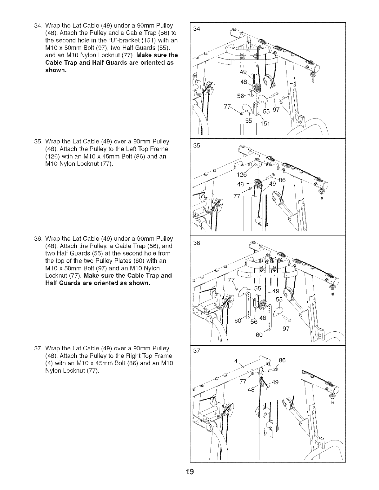
34. Wrap the Lat Cable (49) under a 90mm Pulley
(48). Attach the Pulley and a Cable Trap (56) to
the second hole in the "U'-bracket (151) with an
MIO x 50mm Bolt (97), two Half Guards (55),
and an MIO Nylon Locknut (77). Make sure the
Cable Trap and Half Guards are oriented as
shown.
35. Wrap the Lat Cable (49) over a 90mm Pulley
(48). Attach the Pulley to the Left Top Frame
(126) wtih an MIO x 45mm Bolt (86) and an
MIO Nylon Locknut (77).
36. Wrap the Lat Cable (49) under a 90mm Pulley
(48). Attach the Pulley, a Cable Trap (56), and
two Half Guards (55) at the second hole from
the top of the two Pulley Plates (60) with an
MIO x 50mm Bolt (97) and an MIO Nylon
Locknut (77). Make sure the Cable Trap and
Half Guards are oriented as shown.
37. Wrap the Lat Cable (49) over a 90mm Pulley
(48). Attach the Pulley to the Right Top Frame
(4) with an MIO x 45mm Bolt (86) and an MIO
Nylon Locknut (77).
34
35
36
37
55
77
151
60
77 _49
48/
97
86
19
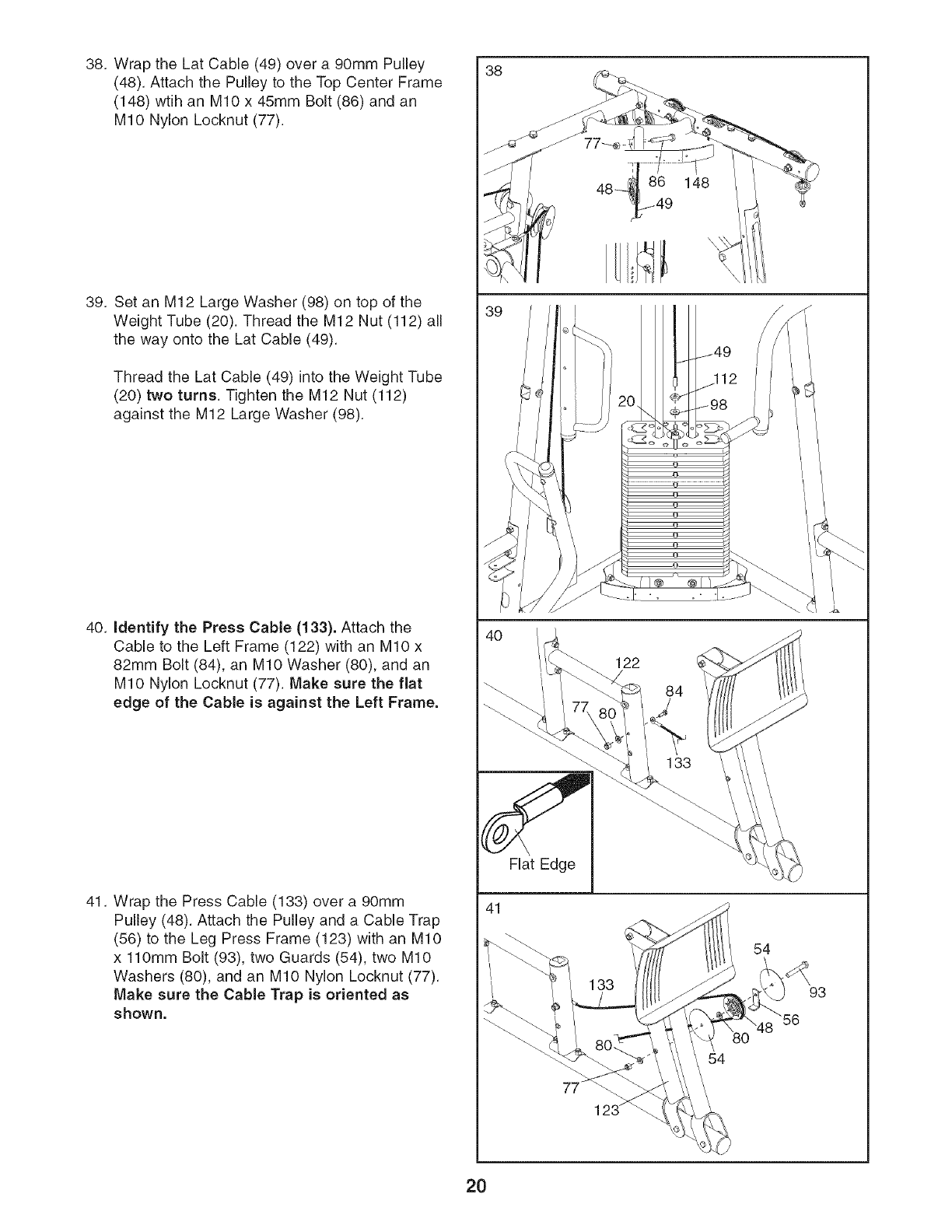
38. Wrap the Lat Cable (49) over a 90mm Pulley
(48). Attach the Pulley to the Top Center Frame
(148) wtih an MIO x 45mm Bolt (86) and an
MIO Nylon Locknut (77).
39. Set an M12 Large Washer (98) on top of the
Weight Tube (20). Thread the M12 Nut (112) all
the way onto the Lat Cable (49).
Thread the Lat Cable (49) into the Weight Tube
(20) two turns. Tighten the M12 Nut (112)
against the M12 Large Washer (98).
40. identify the Press Cable (133). Attach the
Cable to the Left Frame (122) with an MIO x
82mm Bolt (84), an MIO Washer (80), and an
MIO Nylon Locknut (77). Make sure the fiat
edge of the Cable is against the Left Frame.
41. Wrap the Press Cable (133) over a 90mm
Pulley (48). Attach the Pulley and a Cable Trap
(56) to the Leg Press Frame (123) with an MIO
x 110mm Bolt (93), two Guards (54), two MIO
Washers (80), and an MIO Nylon Locknut (77).
Make sure the Cable Trap is oriented as
shown.
38
41
Flat Edge
84
133
54
54
93
2O
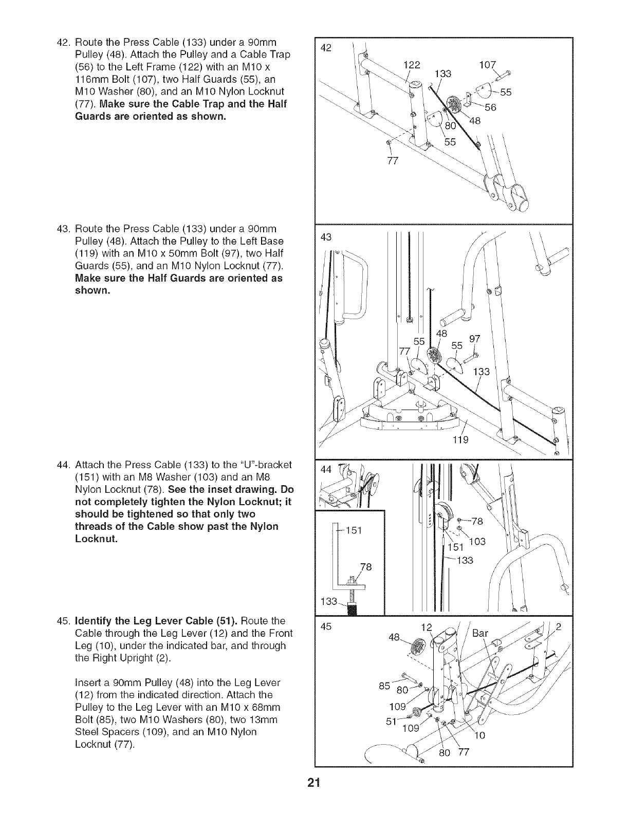
42. Route the Press Cable (133) under a 90mm
Pulley (48). Attach the Pulley and a Cable Trap
(56) to the Left Frame (122) with an MIO x
116mm Bolt (107), two Half Guards (55), an
MIO Washer (80), and an MIO Nylon Locknut
(77). Make sure the Cable Trap and the Half
Guards are oriented as shown.
43. Route the Press Cable (133) under a 90mm
Pulley (48). Attach the Pulley to the Left Base
(119) with an MIO x 50mm Bolt (97), two Half
Guards (55), and an MIO Nylon Locknut (77).
Make sure the Half Guards are oriented as
shown.
44. Attach the Press Cable (133) to the "U'-bracket
(151) with an M8 Washer (103) and an M8
Nylon Locknut (78). See the inset drawing. Do
not completely tighten the Nylon Locknut; it
should be tightened so that only two
threads of the Cable show past the Nylon
Locknut.
45. Identify the Leg Lever Cable (51). Route the
Cable through the Leg Lever (12) and the Front
Leg (10), under the indicated bar, and through
the Right Upright (2).
Insert a 90mm Pulley (48) into the Leg Lever
(12) from the indicated direction. Attach the
Pulley to the Leg Lever with an MIO x 68mm
Bolt (85), two MIO Washers (80), two 13mm
Steel Spacers (109), and an MIO Nylon
Locknut (77).
42
122 133 107
77
43
119
13
45
-151
78
12
80 77
21
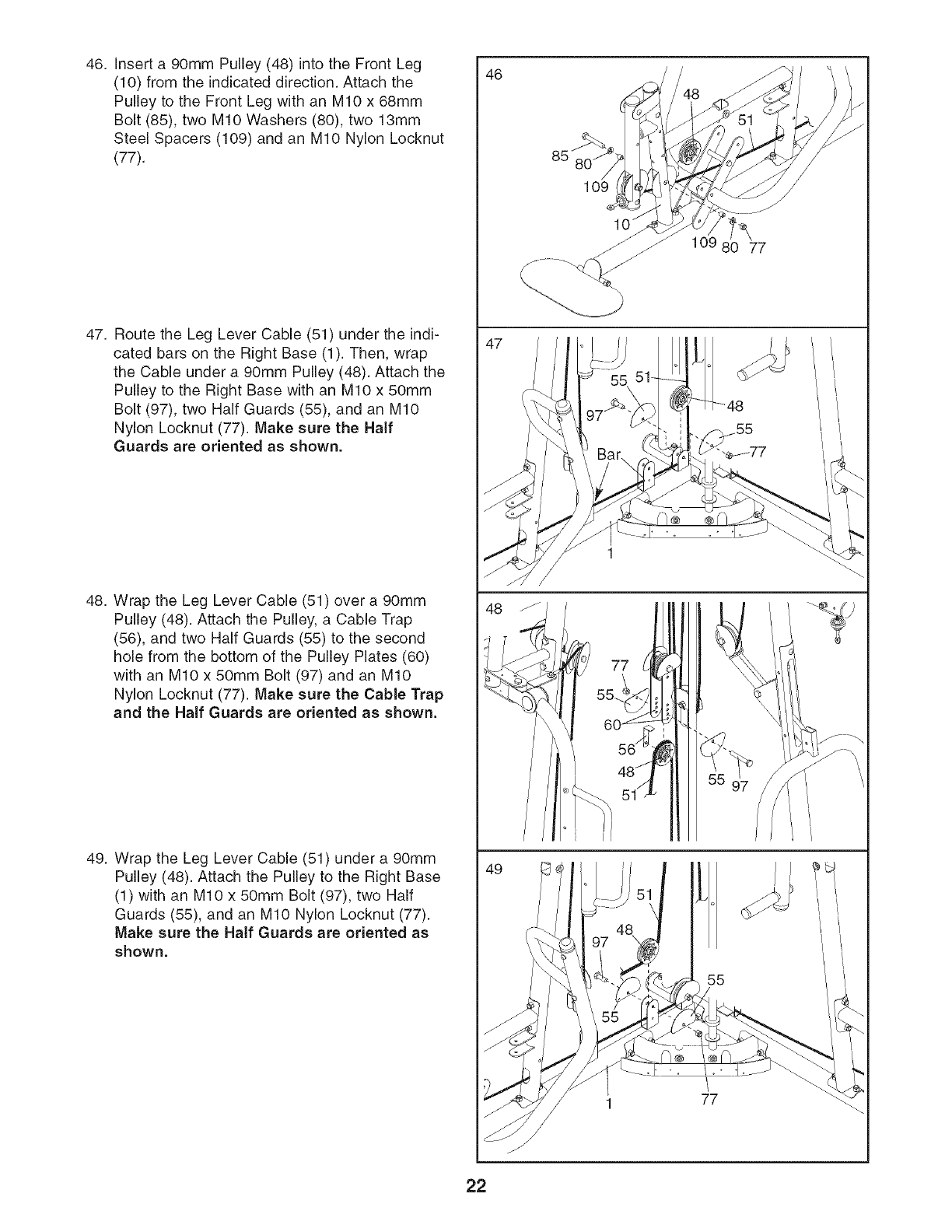
46. Insert a 90mm Pulley (48) into the Front Leg
(10) from the indicated direction. Attach the
Pulley to the Front Leg with an MIO x 68mm
Bolt (85), two MIO Washers (80), two 13mm
Steel Spacers (109) and an MIO Nylon Locknut
(77).
47. Route the Leg Lever Cable (51) under the indi-
cated bars on the Right Base (1). Then, wrap
the Cable under a 90mm Pulley (48). Attach the
Pulley to the Right Base with an MIO x 50mm
Bolt (97), two Half Guards (55), and an MIO
Nylon Locknut (77). Make sure the Half
Guards are oriented as shown.
48. Wrap the Leg Lever Cable (51) over a 90mm
Pulley (48). Attach the Pulley, a Cable Trap
(56), and two Half Guards (55) to the second
hole from the bottom of the Pulley Plates (60)
with an MIO x 50mm Bolt (97) and an MIO
Nylon Locknut (77). Make sure the Cable Trap
and the Half Guards are oriented as shown.
49. Wrap the Leg Lever Cable (51) under a 90mm
Pulley (48). Attach the Pulley to the Right Base
(1) with an MIO x 50mm Bolt (97), two Half
Guards (55), and an MIO Nylon Locknut (77).
Make sure the Half Guards are oriented as
shown.
46
48
49
85"
109
80 77
77
55
51
1 77
22
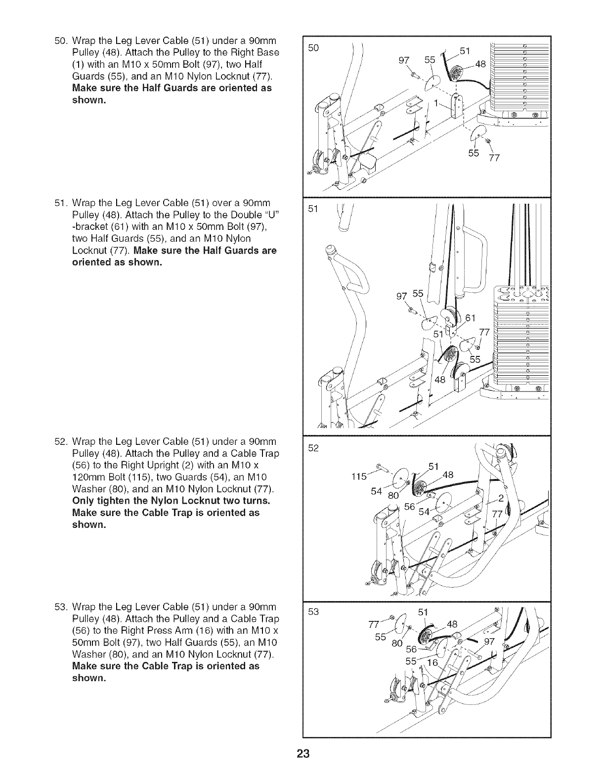
50. Wrap the Leg Lever Cable (51) under a 90mm
Pulley (48). Attach the Pulley to the Right Base
(1) with an MIO x 50mm Bolt (97), two Half
Guards (55), and an MIO Nylon Locknut (77).
Make sure the Half Guards are oriented as
shown.
51. Wrap the Leg Lever Cable (51) over a 90mm
Pulley (48). Attach the Pulley to the Double "U"
-bracket (61) with an MIO x 50mm Bolt (97),
two Half Guards (55), and an MIO Nylon
Locknut (77). Make sure the Half Guards are
oriented as shown.
52. Wrap the Leg Lever Cable (51) under a 90mm
Pulley (48). Attach the Pulley and a Cable Trap
(56) to the Right Upright (2) with an MIO x
120mm Bolt (115), two Guards (54), an MIO
Washer (80), and an MIO Nylon Locknut (77).
Only tighten the Nylon Locknut two turns.
Make sure the Cable Trap is oriented as
shown.
53. Wrap the Leg Lever Cable (51) under a 90mm
Pulley (48). Attach the Pulley and a Cable Trap
(56) to the Right Press Arm (16) with an MIO x
50mm Bolt (97), two Half Guards (55), an MIO
Washer (80), and an MIO Nylon Locknut (77).
Make sure the Cable Trap is oriented as
shown.
50
51
52
53
97
\
97
\
51
55
5577
23
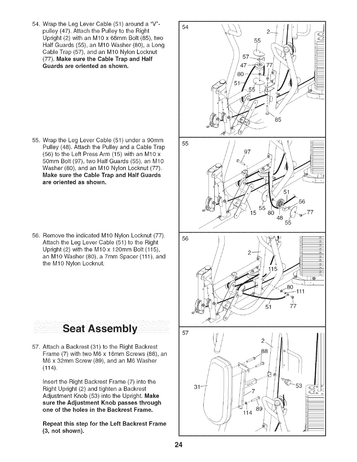
54. Wrap the Leg Lever Cable (51) around a "V'-
pulley (47). Attach the Pulley to the Right
Upright (2) with an MIO x 68mm Bolt (85), two
Half Guards (55), an MIO Washer (80), a Long
Cable Trap (57), and an MIO Nylon Locknut
(77). Make sure the Cable Trap and Half
Guards are oriented as shown.
55. Wrap the Leg Lever Cable (51) under a 90mm
Pulley (48). Attach the Pulley and a Cable Trap
(56) to the Left Press Arm (15) with an MIO x
50mm Bolt (97), two Half Guards (55), an MIO
Washer (80), and an MIO Nylon Locknut (77).
Make sure the Cable Trap and Half Guards
are oriented as shown.
56. Remove the indicated MIO Nylon Locknut (77).
Attach the Leg Lever Cable (51) to the Right
Upright (2) with the MIO x 120mm Bolt (115),
an MIO Washer (80), a 7mm Spacer (111), and
the MIO Nylon Locknut.
Seat Assem bly
57. Attach a Backrest (31) to the Right Backrest
Frame (7) with two M6 x 16mm Screws (88), an
M6 x 32mm Screw (89), and an M6 Washer
(114).
Insert the Right Backrest Frame (7) into the
Right Upright (2) and tighten a Backrest
Adjustment Knob (53) into the Upright. Make
sure the Adjustment Knob passes through
one of the holes in the Backrest Frame.
Repeat this step for the Left Backrest Frame
(3, not shown).
54
55
56
57
55
97
55
15 80 48
51 77
/
2_
88
\ 114
\
24
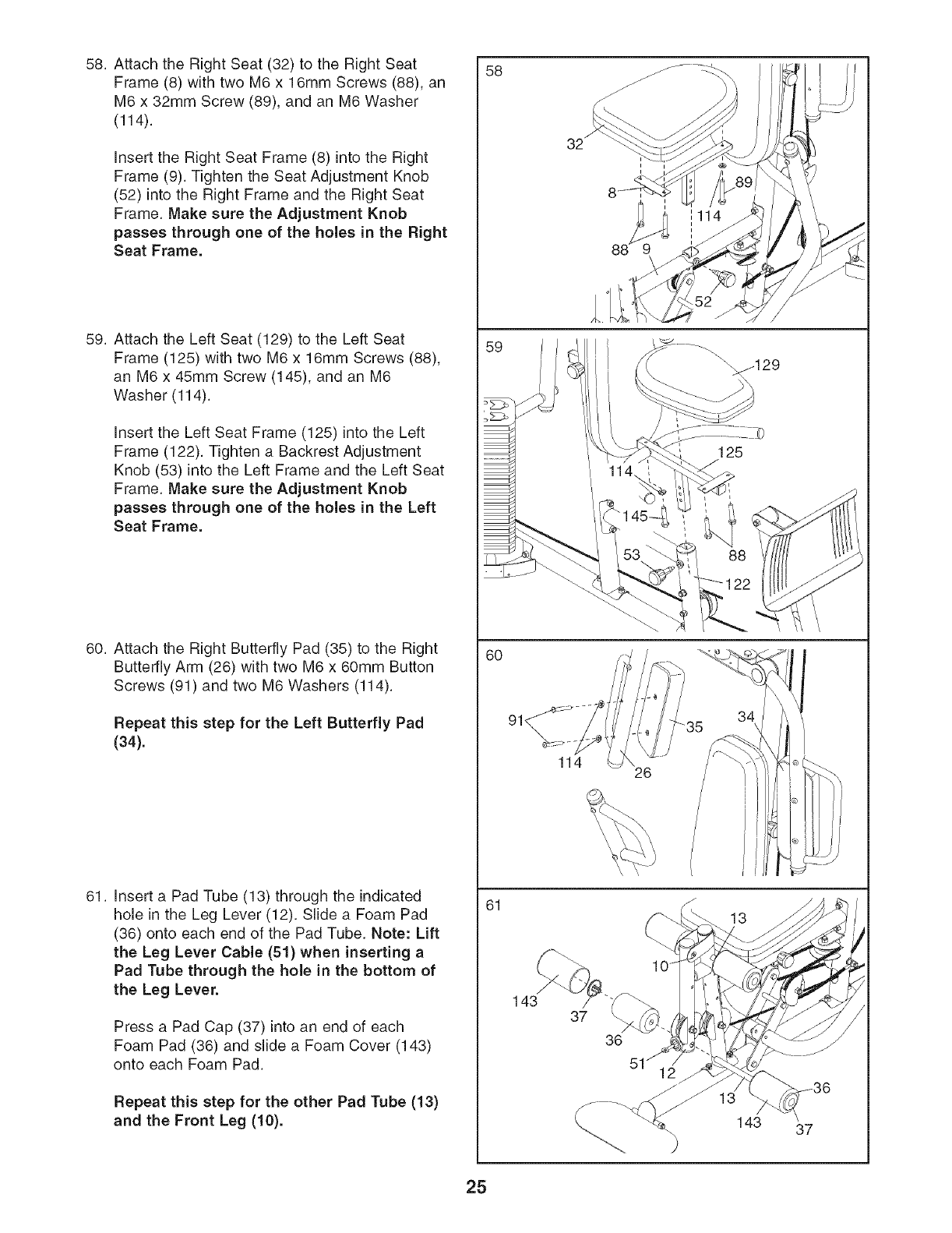
58. Attach the Right Seat (32) to the Right Seat
Frame (8) with two M6 x 16mm Screws (88), an
M6 x 32mm Screw (89), and an M6 Washer
(114).
Insert the Right Seat Frame (8) into the Right
Frame (9). Tighten the Seat Adjustment Knob
(52) into the Right Frame and the Right Seat
Frame. Make sure the Adjustment Knob
passes through one of the holes in the Right
Seat Frame.
59. Attach the Left Seat (129) to the Left Seat
Frame (125) with two M6 x 16mm Screws (88),
an M6 x 45mm Screw (145), and an M6
Washer (114).
insert the Left Seat Frame (125) into the Left
Frame (122). Tighten a Backrest Adjustment
Knob (53) into the Left Frame and the Left Seat
Frame. Make sure the Adjustment Knob
passes through one of the holes in the Left
Seat Frame.
60. Attach the Right Butterfly Pad (35) to the Right
Butterfly Arm (26) with two M6 x 60mm Button
Screws (91) and two M6 Washers (114).
Repeat this step for the Left Butterfly Pad
(34).
61. Insert a Pad Tube (13) through the indicated
hole in the Leg Lever (12). Slide a Foam Pad
(36) onto each end of the Pad Tube. Note: Lift
the Leg Lever Cable (51) when inserting a
Pad Tube through the hole in the bottom of
the Leg Lever.
Press a Pad Cap (37) into an end of each
Foam Pad (36) and slide a Foam Cover (143)
onto each Foam Pad.
Repeat this step for the other Pad Tube (13)
and the Front Leg (10).
58
59
6O
61
114
88
114 26
35 34
13
143 37
36
37
25
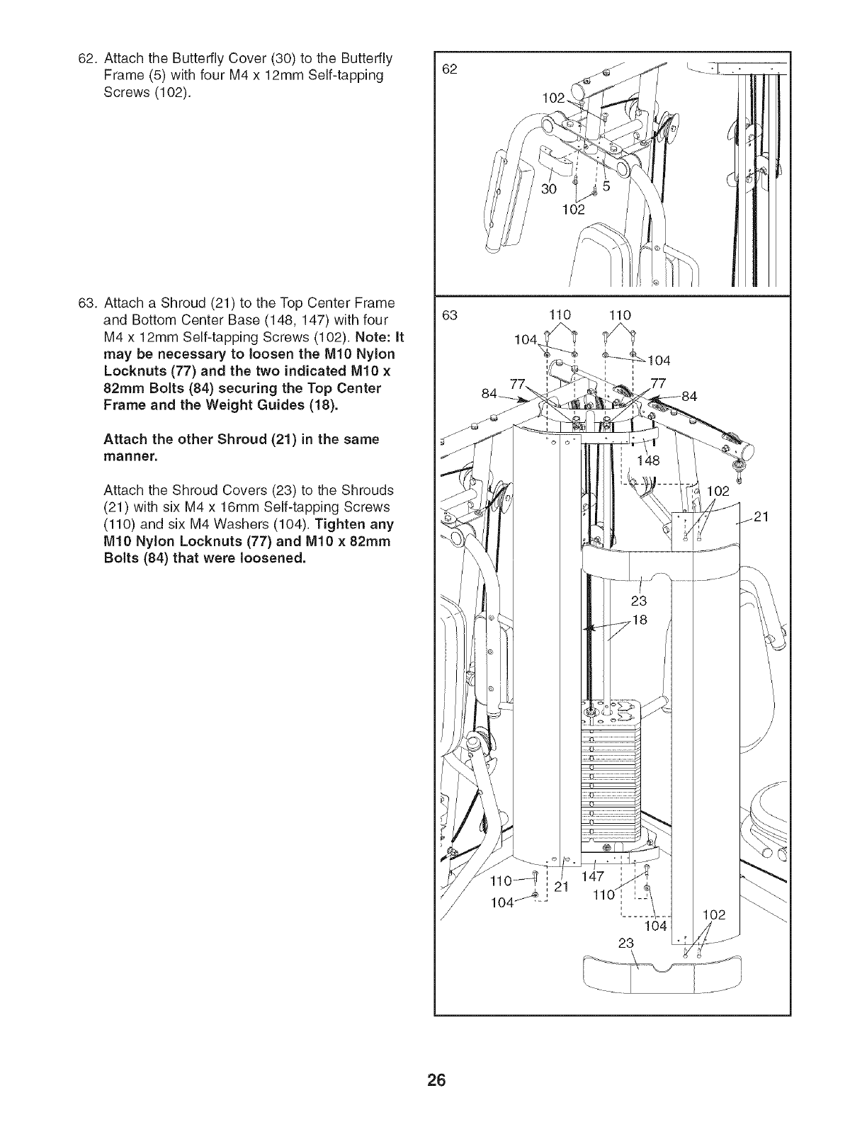
62. Attach the Butterfly Cover (30) to the Butterfly
Frame (5) with four M4 x 12mm Self-tapping
Screws (102).
63. Attach a Shroud (21) to the Top Center Frame
and Bottom Center Base (148, 147) with four
M4 x 12mm Self-tapping Screws (102). Note: It
may be necessary to loosen the M10 Nylon
Locknuts (77) and the two indicated M10 x
82mm Bolts (84) securing the Top Center
Frame and the Weight Guides (18).
Attach the other Shroud (21) in the same
manner.
Attach the Shroud Covers (23) to the Shrouds
(21) with six M4 x 16mm Self-tapping Screws
(110) and six M4 Washers (104). Tighten any
IVll0 Nylon Locknuts (77) and IVll0 x 82mm
Bolts (84) that were loosened.
62
63
102.
102
110
104
26
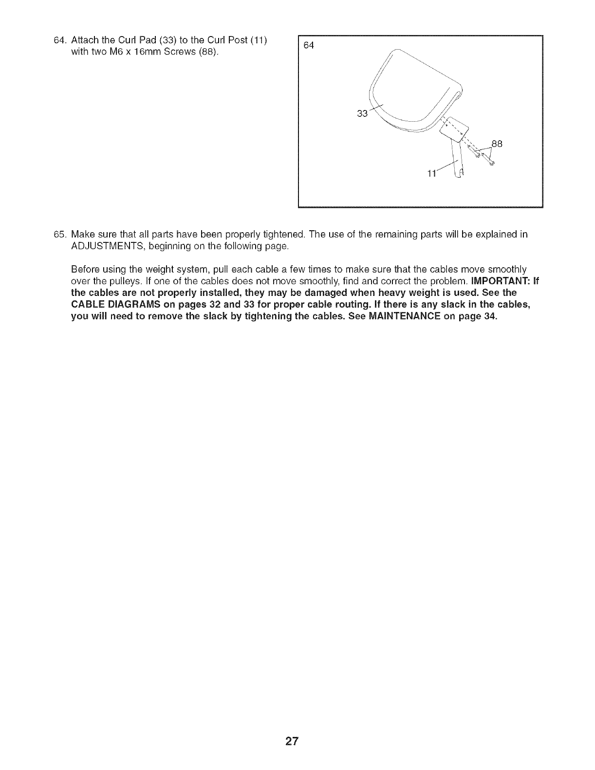
64. Attach the Curl Pad (33) to the Curl Post (11) 64
with two M6 x 16mm Screws (88).
33
65. Make sure that all parts have been properly tightened. The use of the remaining parts will be explained in
ADJUSTMENTS, beginning on the following page.
Before using the weight system, pull each cable a few times to make sure that the cables move smoothly
over the pulleys. If one of the cables does not move smoothly, find and correct the problem, iMPORTANT: If
the cables are not properly installed, they may be damaged when heavy weight is used. See the
CABLE DIAGRAMS on pages 32 and 33 for proper cable routing, if there is any slack in the cables,
you will need to remove the slack by tightening the cables. See MAINTENANCE on page 34.
27
ADJUSTMENTS
This section explains how to adjust the weight system. Refer to the accompanying exercise guide to see the cor-
rect form for each exercise.
Make sure that all parts are properly tightened each time the weight system is used. Replace any worn parts
immediately. The weight system can be cleaned with a damp cloth and a mild, non-abrasive detergent. Do not
use solvents.
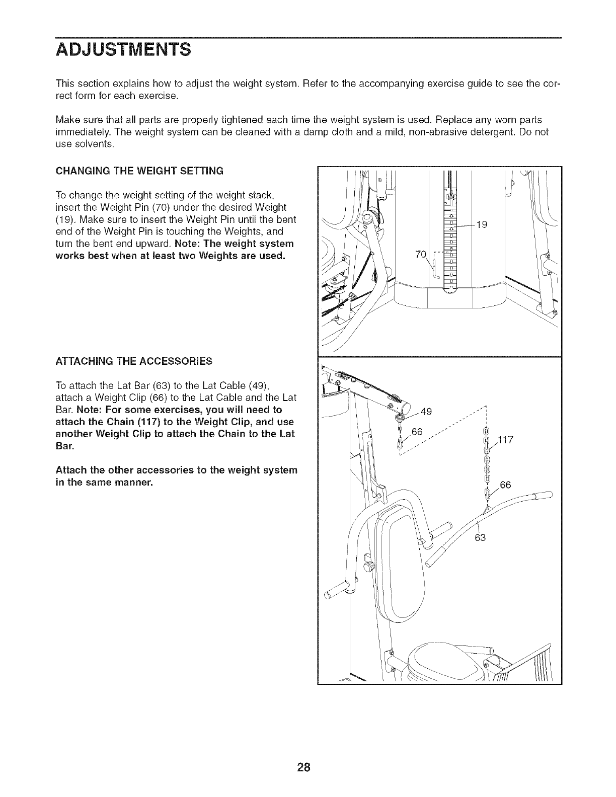
CHANGING THE WEIGHT SETTING
To change the weight setting of the weight stack,
insert the Weight Pin (70) under the desired Weight
(19). Make sure to insert the Weight Pin until the bent
end of the Weight Pin is touching the Weights, and
turn the bent end upward. Note: The weight system
works best when at least two Weights are used.
ATTACHING THE ACCESSORIES
To attach the Lat Bar (63) to the Lat Cable (49),
attach a Weight Clip (66) to the Lat Cable and the Lat
Bar. Note: For some exercises, you will need to
attach the Chain (117) to the Weight Clip, and use
another Weight Clip to attach the Chain to the Lat
Bar.
Attach the other accessories to the weight system
in the same manner.
63
28
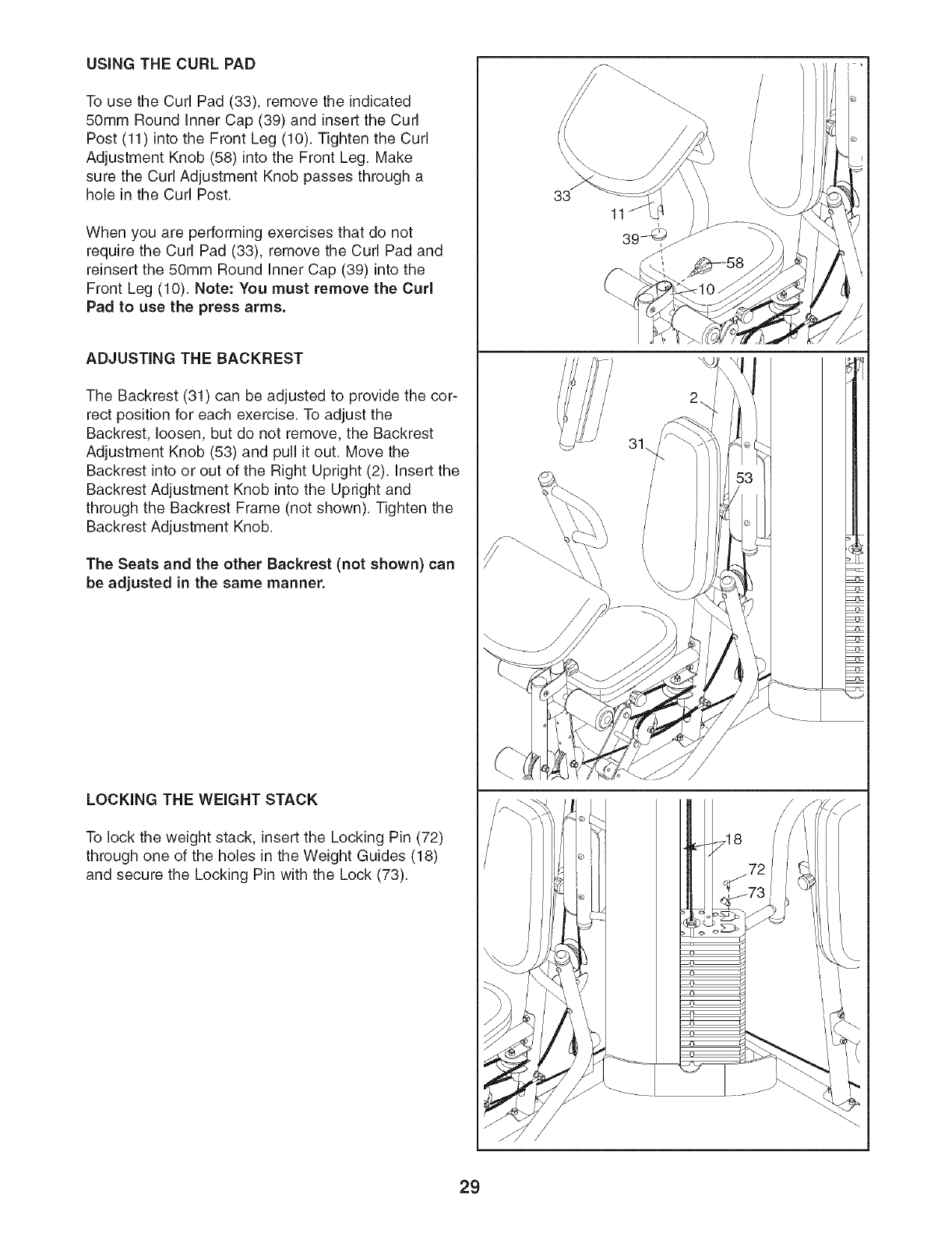
USING THE CURL PAD
To use the Curl Pad (33), remove the indicated
50mm Round Inner Cap (39) and insert the Curl
Post (11) into the Front Leg (10). Tighten the Curl
Adjustment Knob (58) into the Front Leg. Make
sure the Curl Adjustment Knob passes through a
hole in the Curl Post.
When you are performing exercises that do not
require the Curl Pad (33), remove the Curl Pad and
reinsert the 50mm Round Inner Cap (39) into the
Front Leg (10). Note: You must remove the Curl
Pad to use the press arms.
ADJUSTING THE BACKREST
The Backrest (31) can be adjusted to provide the cor-
rect position for each exercise. To adjust the
Backrest, loosen, but do not remove, the Backrest
Adjustment Knob (53) and pull it out. Move the
Backrest into or out of the Right Upright (2). Insert the
Backrest Adjustment Knob into the Upright and
through the Backrest Frame (not shown). Tighten the
Backrest Adjustment Knob.
The Seats and the other Backrest (not shown) can
be adjusted in the same manner.
LOCKING THE WEIGHT STACK
To lock the weight stack, insert the Locking Pin (72)
through one of the holes in the Weight Guides (18)
and secure the Locking Pin with the Lock (73).
33
11
29
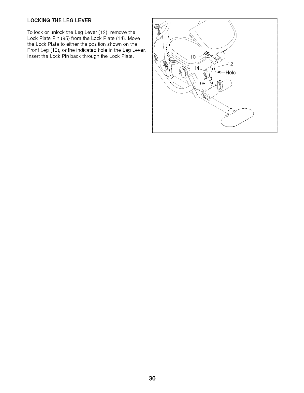
LOCKING THE LEG LEVER
To lock or unlock the Leg Lever (12), remove the
Lock Plate Pin (95) from the Lock Plate (14). Move
the Lock Plate to either the position shown on the
Front Leg (10), or the indicated hole in the Leg Lever.
Insert the Lock Pin back through the Lock Plate.
3O
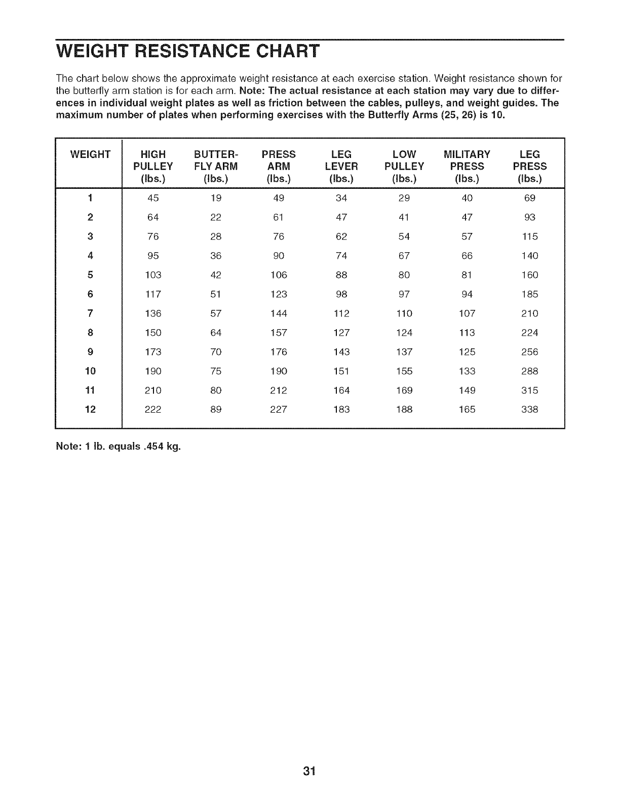
WEIGHT RESISTANCE CHART
The chart below shows the approximate weight resistance at each exercise station. Weight resistance shown for
the butterfly arm station is for each arm. Note: The actual resistance at each station may vary due to differ-
ences in individual weight plates as well as friction between the cables, pulleys, and weight guides. The
maximum number of plates when performing exercises with the Butterfly Arms (25, 26) is 10.
WEIGHT
1
2
3
4
5
6
7
8
9
10
11
12
HIGH BUTTER- PRESS LEG LOW MILITARY LEG
PULLEY FLY ARM ARM LEVER PULLEY PRESS PRESS
(Ibs.) (Ibs.) (Ibs.) (Ibs.) (Ibs.) (Ibs.) (Ibs.)
45 19 49 34 29 40 69
64 22 61 47 41 47 93
76 28 76 62 54 57 115
95 36 90 74 67 66 140
103 42 106 88 80 81 160
117 51 123 98 97 94 185
136 57 144 112 110 107 210
150 64 157 127 124 113 224
173 70 176 143 137 125 256
190 75 190 151 155 133 288
210 80 212 164 169 149 315
222 89 227 183 188 165 338
Note: 1 lb. equals .454 kg.
31
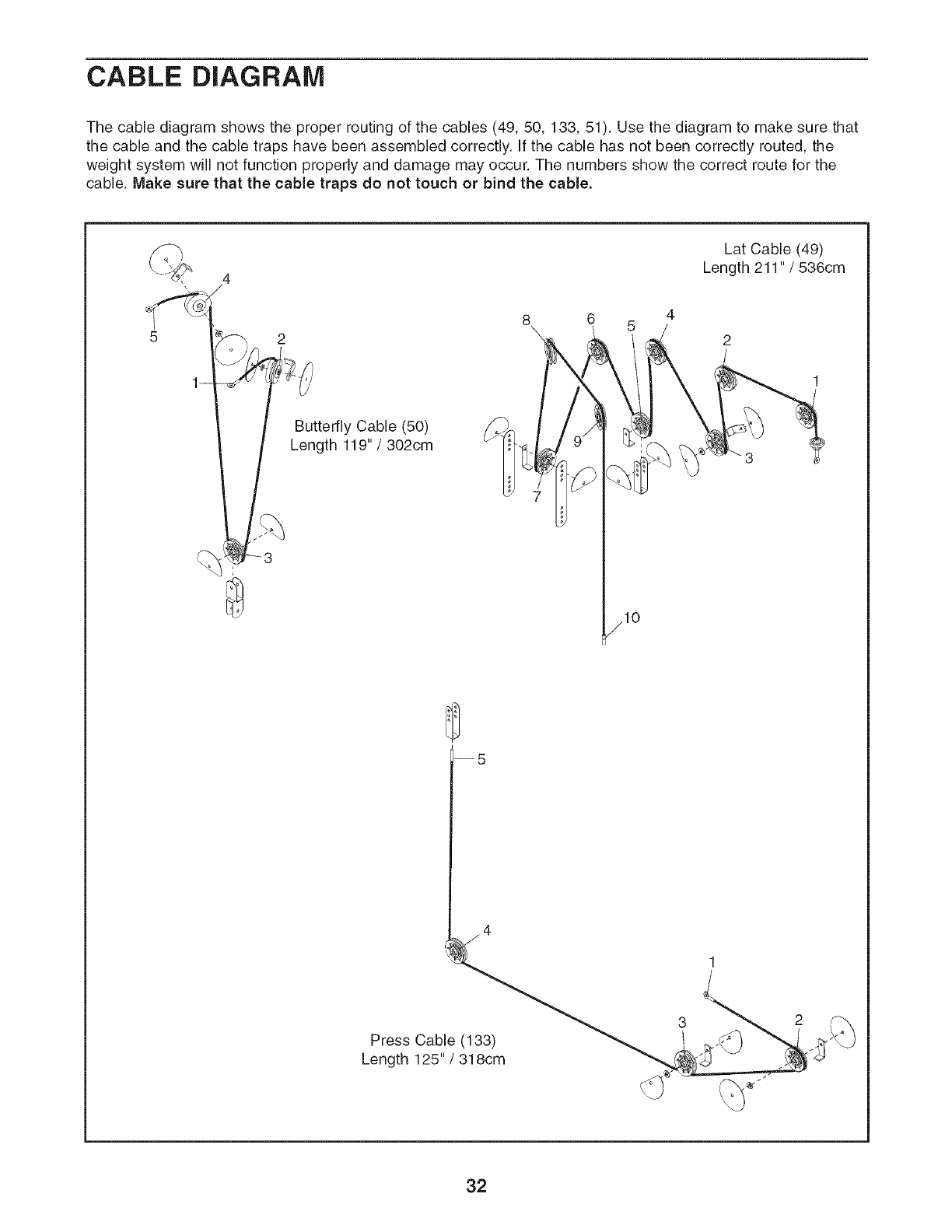
CABLE DIAGRAM
The cable diagram shows the proper routing of the cables (49, 50, 133, 51). Use the diagram to make sure that
the cable and the cable traps have been assembled correctly. If the cable has not been correctly routed, the
weight system will not function properly and damage may occur. The numbers show the correct route for the
cable. Make sure that the cable traps do not touch or bind the cable.
Lat Cable (49)
Length 211 "/536cm
4
2
Butterfly Cable (50)
Length 119" /302cm
jlO
Press Cable (133)
Length 125" /318cm
32
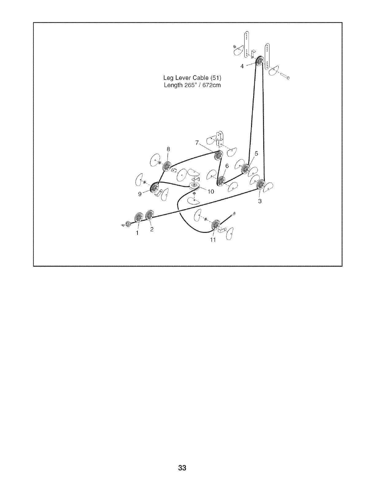
Leg Lever Cable (51)
Length 265" /672cm
11
33
MAINTENANCE
Make sure all parts are properly tightened each time the weight system is used. Replace any worn parts imme-
diately. The weight system can be cleaned with a damp cloth and a mild, non-abrasive detergent. Do not use
solvents.
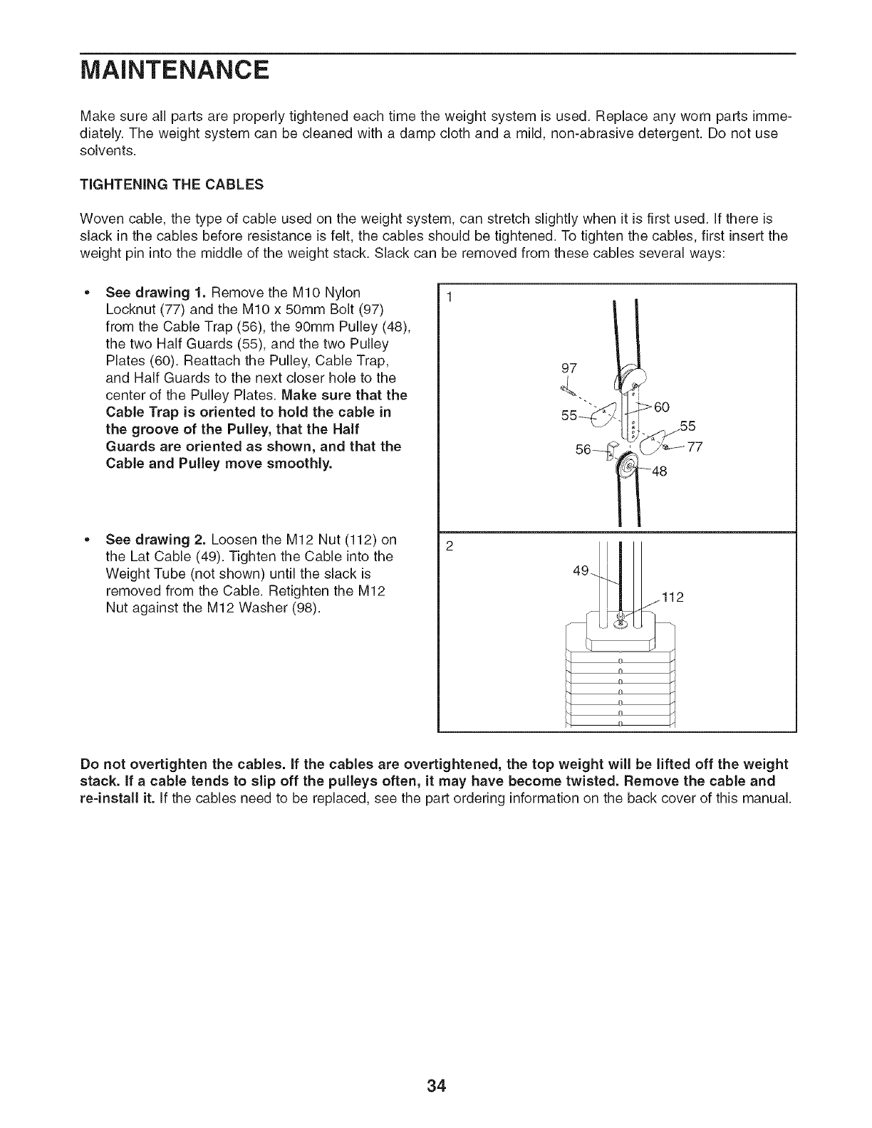
TiGHTENiNG THE CABLES
Woven cable, the type of cable used on the weight system, can stretch slightly when it is first used. If there is
slack in the cables before resistance is felt, the cables should be tightened. To tighten the cables, first insert the
weight pin into the middle of the weight stack. Slack can be removed from these cables several ways:
See drawing 1. Remove the MIO Nylon
Locknut (77) and the MIO x 50mm Bolt (97)
from the Cable Trap (56), the 90mm Pulley (48),
the two Half Guards (55), and the two Pulley
Plates (60). Reattach the Pulley, Cable Trap,
and Half Guards to the next closer hole to the
center of the Pulley Plates. Make sure that the
Cable Trap is oriented to hold the cable in
the groove of the Pulley, that the Half
Guards are oriented as shown, and that the
Cable and Pulley move smoothly.
See drawing 2. Loosen the M12 Nut (112) on
the Lat Cable (49). Tighten the Cable into the
Weight Tube (not shown) until the slack is
removed from the Cable. Retighten the M12
Nut against the M12 Washer (98).
97
>60
0
Do not overtighten the cables, if the cables are overtightened, the top weight will be lifted off the weight
stack, if a cable tends to slip off the pulleys often, it may have become twisted. Remove the cable and
re=install it. If the cables need to be replaced, see the part ordering information on the back cover of this manual.
34
EXERCISE GUiDELiNES
THE FOUR BASIC TYPES OF WORKOUTS
Muscle Building
To increase the size and strength of your muscles,
push them dose to their maximum capacity. Your mus-
cles will continually adapt and grow as you progres-
sively increase the intensity of your exercise. You can
adjust the intensity level of an individual exercise in
two ways:
• by changing the amount of weight used
• by changing the number of repetitions or sets per-
formed. (A "repetition" is one complete cycle of an
exercise, such as one sit-up. A "set" is a series of
repetitions.)
The proper amount of weight for each exercise
depends upon the individual user. You must gauge
your limits and select the amount of weight that is right
for you. Begin with 3 sets of 8 repetitions for each
exercise you perform. Rest for three minutes after
each set. When you can complete 3 sets of 12 repeti-
tions without difficulty, increase the amount of weight.
Toning
You can tone your muscles by pushing them to a mod-
erate percentage of their capacity. Select a moderate
amount of weight and increase the number of repeti-
tions in each set. Complete as many sets of 15 to 20
repetitions as possible without discomfort. Rest for one
minute after each set. Work your muscles by complet-
ing more sets rather than by using high amounts of
weight.
Weight Loss
To lose weight, use a low amount of weight and
increase the number of repetitions in each set.
Exercise for 20 to 30 minutes, resting for a maximum
of 30 seconds between sets.
Cross Training
Cross training is an efficient way to implement a com-
plete and well-balanced fitness program. An example
of a balanced program follows:
• Plan strength training workouts on Monday,
Wednesday, and Friday.
• Plan 20 to 30 minutes of aerobic exercise, such as
running on a treadmill or riding on an elliptical exer-
ciser or exercise cycle, on Tuesday and Thursday.
• Rest from both strength training and aerobic exercise
for at least one full day each week to give your body
time to regenerate.
The combination of strength training and aerobic exer-
cise will reshape and strengthen your body, plus devel-
op your heart and lungs.
PERSONALIZING YOUR EXERCISE PROGRAM
Determining the exact length of time for each workout,
as well as the number of repetitions or sets completed,
is an individual matter. It is important to avoid overex-
erting yourself during the first few months of your exer-
cise program. You should progress at your own pace
and be sensitive to your body's signals. If you experi-
ence pain or dizziness at any time while exercising,
stop immediately and begin cooling down. Find out
what is wrong before continuing. Remember that ade-
quate rest and a proper diet are important factors in
any exercise program.
WARMING UP
Begin each workout with 5 to 10 minutes of stretching
and light exercise to warm up. Warming up prepares
your body for more strenuous exercise by increasing
circulation, raising your body temperature and deliver-
ing more oxygen to your muscles.
WORKING OUT
Each workout should include 6 to 10 different exercis-
es. Select exercises for every major muscle group,
emphasizing areas that you want to develop most. To
give balance and variety to your workouts, vary the
exercises from session to session.
Schedule your workouts for the time of day when your
energy level is the highest. Each workout should be
followed by at least one day of rest. Once you find the
schedule that is right for you, stick with it.
EXERCISE FORM
Maintaining proper form is an essential part of an
effective exercise program. This requires moving
through the full range of motion for each exercise, and
moving only the appropriate parts of the body.
Exercising in an uncontrolled manner will leave you
feeling exhausted. On the exercise guide accompany-
ing this manual you will find photographs showing the
correct form for several exercises, and a list of the
muscles affected. See the muscle chart on the next
page to find the names of the muscles.
The repetitions in each set should be performed
smoothly and without pausing. The exertion stage of
each repetition should last about half as long as the
return stage. Proper breathing is important. Exhale
during the exertion stage of each repetition and inhale
during the return stroke. Never hold your breath.
35
Rest for a short period of time after each set. The
ideal resting periods follow:
• Rest for three minutes after each set for a muscle
building workout.
Rest for one minute after each set for a toning work-
out.
Rest for 30 seconds after each set for a weight loss
workout.
Plan to spend the first couple of weeks familiarizing
yourself with the equipment and learning the proper
form for each exercise.
COOLING DOWN
End each workout with 5 to 10 minutes of stretching.
Include stretches for both your arms and legs. Move
slowly as you stretch and do not bounce. Ease into
each stretch gradually and go only as far as you can
without strain. Stretching at the end of each workout
is an effective way to increase flexibility.
STAYING MOTIVATED
For motivation, keep a record of each workout. The
chart on pages 37, 38 can be photocopied and used
to schedule and record your workouts. List the date,
the exercises performed, the weight used, and the
numbers of sets and repetitions completed. Record
your weight and key body measurements at the end of
every month. Remember, the key to achieving the
greatest results is to make exercise a regular and
enjoyable part of your everyday life.
R
S
T
V
W
X
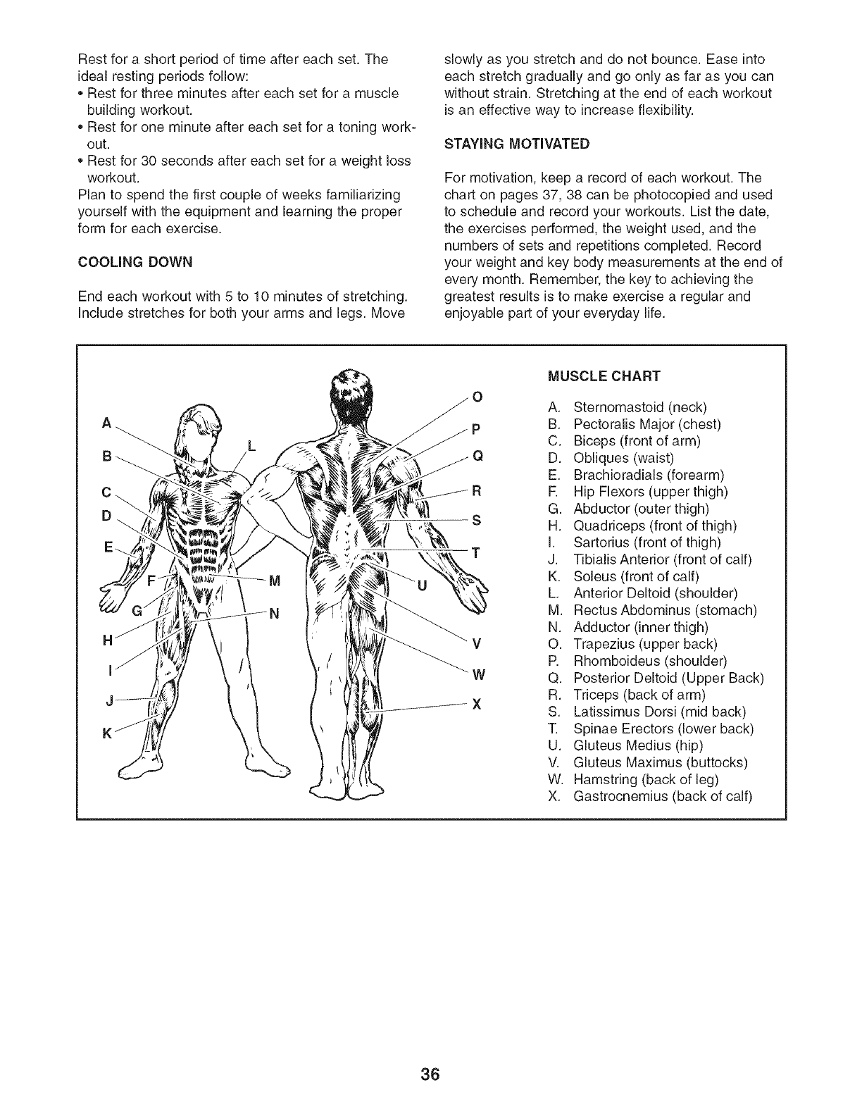
MUSCLE CHART
A. Sternomastoid (neck)
B. Pectoralis Major (chest)
C. Biceps (front of arm)
D. Obliques (waist)
E. Brachioradials (forearm)
R Hip Flexors (upper thigh)
G. Abductor (outer thigh)
H. Quadriceps (front of thigh)
I. Sartodus (front of thigh)
J. Tibialis Anterior (front of calf)
K. Soleus (front of calf)
L. Anterior Deltoid (shoulder)
M. RectusAbdominus (stomach)
N. Adductor (inner thigh)
O. Trapezius (upper back)
P. Rhomboideus (shoulder)
Q. Posterior Deltoid (Upper Back)
R. Triceps (back of arm)
S. Latissimus Dorsi (mid back)
T. Spinae Erectors (lower back)
U. Gluteus Medius (hip)
V. Gluteus Maximus (buttocks)
W. Hamstring (back of leg)
X. Gastrocnemius (back of calf)
36
MONDAY EXERCISE WEIGHT SETS REPS
Date:
/ /
TUESDAY
Date:
/ /
AEROBIC EXERCISE
WEDNESDAY EXERCISE WEIGHT SETS REPS
Date:
/ /
THURSDAY
Date:
/ /
AEROBIC EXERCISE
FRIDAY EXERCISE WEIGHT SETS REPS
Date:
/ /
Make photocopies of this page for scheduling and recording your workouts.
37
MONDAY EXERCISE WEIGHT SETS REPS
Date:
/ /
TUESDAY
Date:
/ /
AEROBIC EXERCISE
WEDNESDAY EXERCISE WEIGHT SETS REPS
Date:
/ /
THURSDAY
Date:
/ /
AEROBIC EXERCISE
FRIDAY EXERCISE WEIGHT SETS REPS
Date:
/ /
Make photocopies of this page for scheduling and recording your workouts.
38
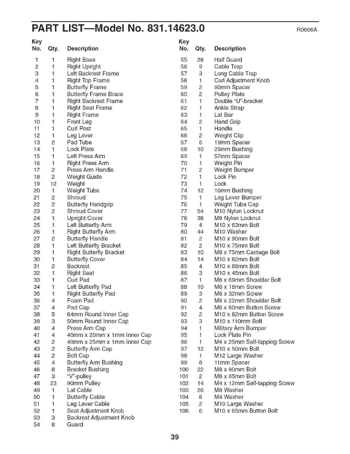
PART LIST--iVlodei No. 831.14623.0 RO606A
Key Key
No. Qty. Description No.
1 1 Right Base
2 1 Right Upright
3 1 Left Backrest Frame
4 1 Right Top Frame
5 1 Butterfly Frame
6 1 Butterfly Frame Brace
7 1 Right Backrest Frame
8 1 Right Seat Frame
9 1 Right Frame
10 1 Front Leg
11 1 Curl Post
12 1 Leg Lever
13 2 Pad Tube
14 1 Lock Plate
15 1 Left Press Arm
16 1 Right Press Arm
17 2 Press Arm Handle
18 2 Weight Guide
19 12 Weight
20 1 Weight Tube
21 2 Shroud
22 2 Butterfly Handgdp
23 2 Shroud Cover
24 1 Upright Cover
25 1 Left Butterfly Arm
26 1 Right Butterfly Arm
27 2 Butterfly Handle
28 1 Left Butterfly Bracket
29 1 Right Butterfly Bracket
30 1 Butterfly Cover
31 2 Backrest
32 1 Right Seat
33 1 Curl Pad
34 1 Left Butterfly Pad
35 1 Right Butterfly Pad
36 4 Foam Pad
37 4 Pad Cap
38 5 64mm Round Inner Cap
39 3 50mm Round Inner Cap
40 4 Press Arm Cap
41 4 40mm x 20mm x 1mm Inner Cap
42 2 40mm x 25mm x 1mm Inner Cap
43 2 Butterfly Arm Cap
44 2 Bolt Cap
45 4 Butterfly Arm Bushing
46 8 Bracket Bushing
47 3 "V"-pulley
48 23 90mm Pulley
49 1 Lat Cable
50 1 Butterfly Cable
51 1 Leg Lever Cable
52 1 Seat Adjustment Knob
53 3 Backrest Adjustment Knob
54 8 Guard
Qty. Description
55 28 Half Guard
56 9 Cable Trap
57 3 Long Cable Trap
58 1 Curl Adjustment Knob
59 2 90mm Spacer
60 2 Pulley Plate
61 1 Double "U"-bracket
62 1 Ankle Strap
63 1 Lat Bar
64 2 Hand Grip
65 1 Handle
66 2 Weight Clip
67 6 19mm Spacer
68 10 25mm Bushing
69 1 57mm Spacer
70 1 Weight Pin
71 2 Weight Bumper
72 1 Lock Pin
73 1 Lock
74 12 16mm Bushing
75 1 Leg Lever Bumper
76 1 Weight Tube Cap
77 54 MIO Nylon Locknut
78 38 M8 Nylon Locknut
79 4 MIO x 63mm Bolt
80 44 MIO Washer
81 2 MIO x 90mm Bolt
82 2 MIO x 75mm Bolt
83 10 M8 x 75mm Carriage Bolt
84 14 MIO x 82mm Bolt
85 4 MIO x 68mm Bolt
86 3 MIO x 45mm Bolt
87 1 M8 x 69mm Shoulder Bolt
88 10 M6 x 16mm Screw
89 3 M6 x 32mm Screw
90 2 M8 x 22mm Shoulder Bolt
91 4 M6 x 60mm Button Screw
92 2 MIO x 82mm Button Screw
93 3 MIO x 110mm Bolt
94 1 Military Arm Bumper
95 1 Lock Plate Pin
96 1 M4 x 25mm Self-tapping Screw
97 12 MIO x 50mm Bolt
98 1 M12 Large Washer
99 8 11mm Spacer
100 22 M8 x 80mm Bolt
101 2 M8 x 65mm Bolt
102 14 M4 x 12mm Self-tapping Screw
103 26 M8 Washer
104 8 M4 Washer
105 2 MIO Large Washer
106 6 MIO x 65mm Button Bolt
39
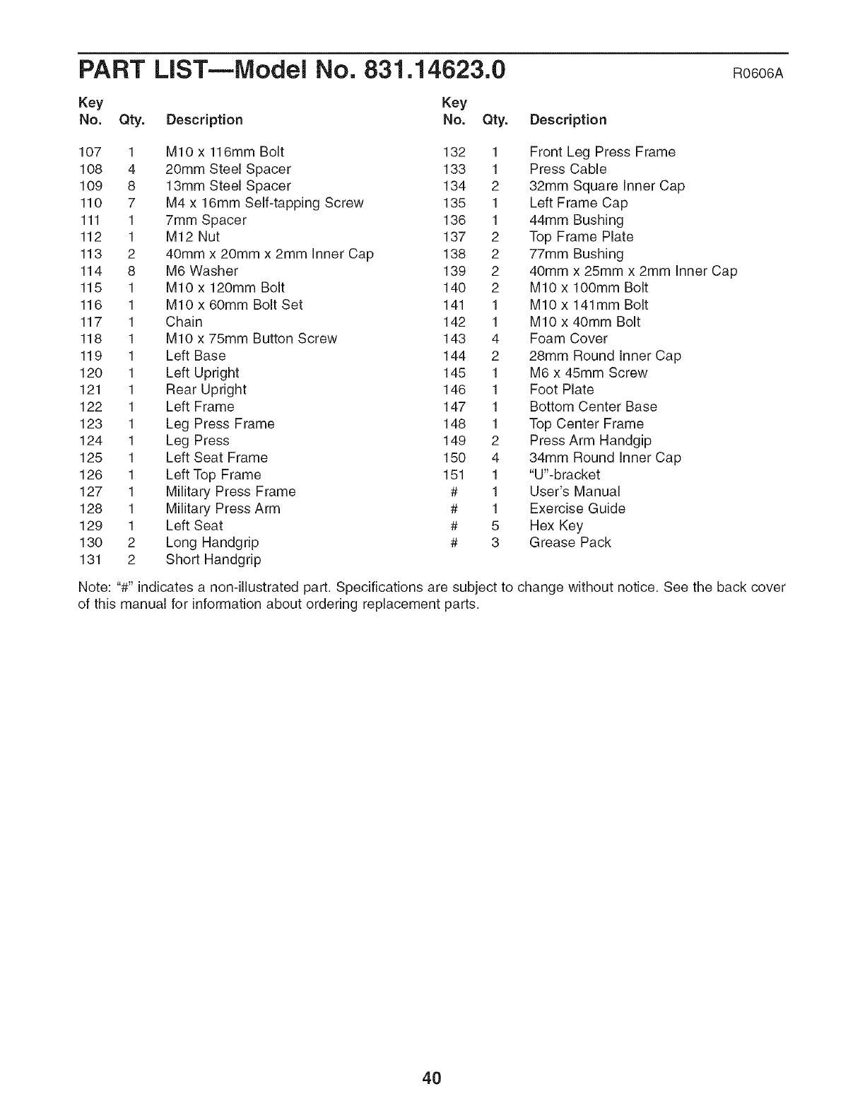
PART LiST--Model No. 831.14623.0 RO606A
Key Key
No. Qty. Description No. Qty. Description
107 1 M10 x 116mm Bolt 132 1 Front Leg Press Frame
108 4 20mm Steel Spacer 133 1 Press Cable
109 8 13mm Steel Spacer 134 2 32mm Square Inner Cap
110 7 M4 x 16mm Self-tapping Screw 135 1 Left Frame Cap
111 1 7mm Spacer 136 1 44mm Bushing
112 1 M12 Nut 137 2 Top Frame Plate
113 2 40mm x 20mm x 2mm Inner Cap 138 2 77mm Bushing
114 8 M6 Washer 139 2 40mm x 25mm x 2mm Inner Cap
115 1 MIO x 120mm Bolt 140 2 MIO x lOOmm Bolt
116 1 MIO x 60mm Bolt Set 141 1 MIO x 141mm Bolt
117 1 Chain 142 1 MIO x 40mm Bolt
118 1 MIO x 75mm Button Screw 143 4 Foam Cover
119 1 Left Base 144 2 28mm Round Inner Cap
120 1 Left Upright 145 1 M6 x 45mm Screw
121 1 Rear Upright 146 1 Foot Plate
122 1 Left Frame 147 1 Bottom Center Base
123 1 Leg Press Frame 148 1 Top Center Frame
124 1 Leg Press 149 2 Press Arm Handgip
125 1 Left Seat Frame 150 4 34mm Round Inner Cap
126 1 Left Top Frame 151 1 "U'-bracket
127 1 Military Press Frame # 1 User's Manual
128 1 Military Press Arm # 1 Exercise Guide
129 1 Left Seat # 5 Hex Key
130 2 Long Handgrip # 3 Grease Pack
131 2 Short Handgrip
Note: "#" indicates a non-illustrated part. Specifications are subject to change without notice. See the back cover
of this manual for information about ordering replacement parts.
4O
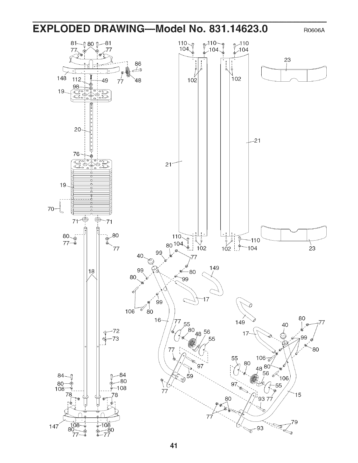
EXPLODED DRAWING--Model No. 831.14623.0
148 112
19_
19_
20,q_
i
i
i
i
i
i
i
76--,,_
i
e
71_ _71
77
86
==-,180
77
_72
_b_-73
106
99
99
8O
1
77
,_ 80
"99
149
,77 55 149
56
/55
23
40
106-
41
RO606A
23
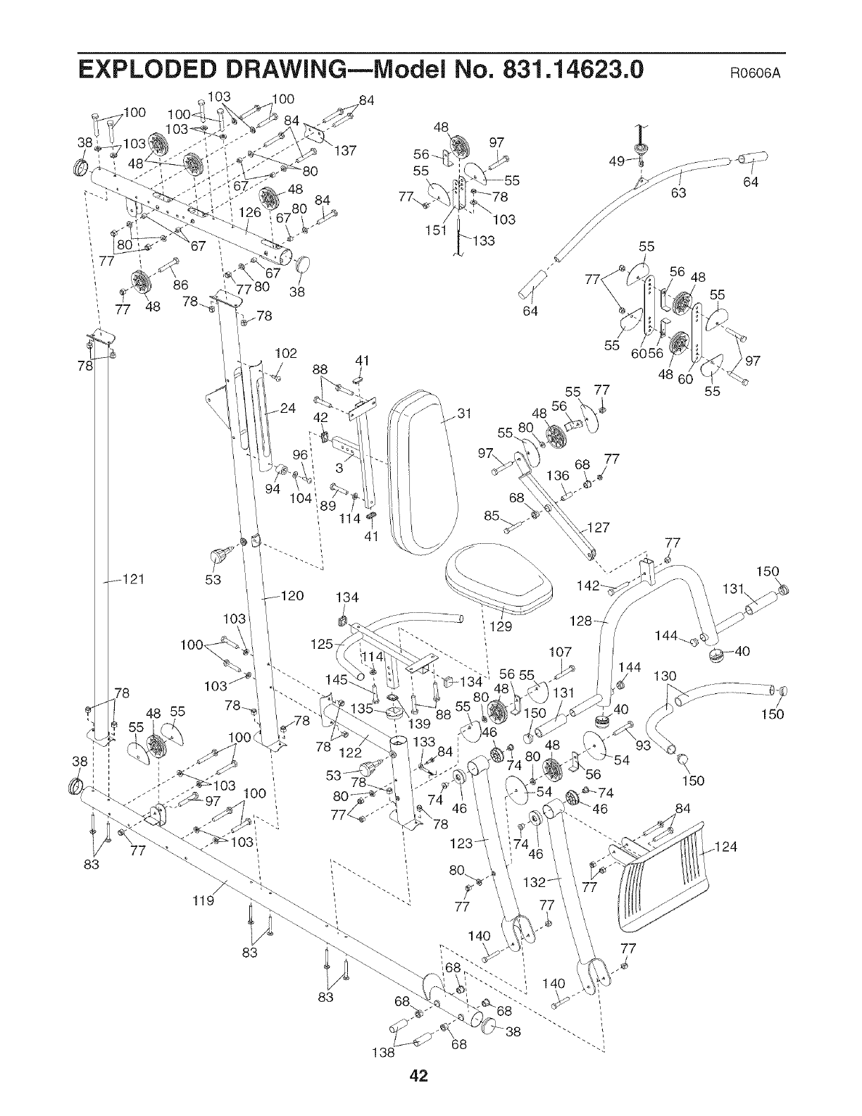
EXPLODED DRAWING--Model No. 831.14623.0 RO606A
77 48
78
-121
78
38
83
103 O0 84
53
119
-48
38
102
88
104
83
84
41
114
41
134
125
83
55
7\
138
48 97
__ 103
151 133
64
/48
55
.31
68 77
27
1
48
77
55
i129
107
130
77
150
84
150
150
42
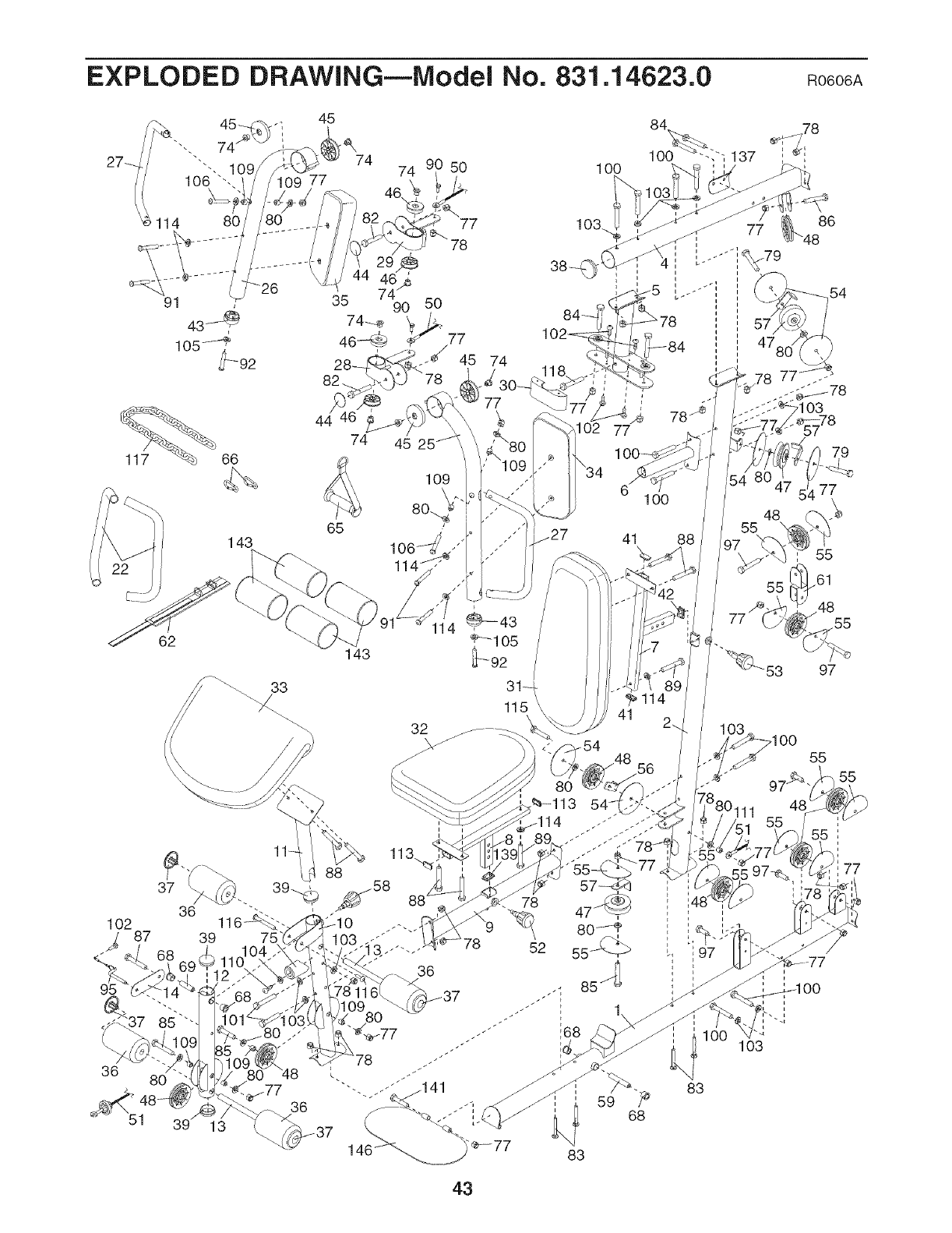
EXPLODED DRAWING--IVlodei No. 831.14623.0 RO606A
45
62
74 9 50 100
1O2
_ 87
95
36 1
39
77
36 8O
74 45
109
65 /
143 106 _/_,_
33
£.
84
IO0
36
36
61O0
41 88
'I_ 114
115 41
78 4_ i
8o_
83
59 68
103
83
55
77
43

Your Home
For repair--in your home--of all major brand appliances, lawn and garden equipment,
or heating and cooling systems, no matter who made it, no matter who sold it!
For the replacement parts, accessories, and user's manuals that you need to do-it-yourself.
For Sears professional installation of home appliances
and items like garage door openers and water heaters.
1-800-4-MY-HOME ®(1-800-469-4663)
Call anytime, day or night (U.S.A. and Canada)
WWW, sears, Gem www, sears=ca
Our Home
For repair of carry-in items like vacuums, lawn equipment,
and electronics, call or go on-line for the location of your nearest
Sears Parts & Repair Center.
1-800-488-1222 Call anytime, day or night (U.S.A. only)
WWW=Sears.com
To purchase a protection agreement (U.S.A.)
or maintenance agreement (Canada) on a product serviced by Sears:
1-800-827-6655 (U.S.A.) 1-800-361-6665 (Canada) ..............
Pard pedir servicio de reparacidn a domicilio, y pard ordenar piezas:
1-888-SU-HOGAR c_(1-888-784-6427)
Sears
® Registered Trademark /TMTrademark /SMService Mark of Sears Brands, LLC
® Marca Registrada /TMMarca de Fabrica /SMMarca de Servicio de Sears Brands, LLC
90 DAY FULL WARRANTY
If this Sears WEIGHT SYSTEM EXERCISER fails due to a defect in material or workmanship within 90
days of the date of purchase, call 1-800-4-MY-HOME _)(1-800-469-4663) to arrange for free repair (or
replacement if repair proves impossible).
This warranty does not apply when the WEIGHT SYSTEM EXERCISER is used commercially or for
rental purposes. This warranty gives you specific legal rights, and you may also have other rights which
vary from state to state.
Sears, Roebuck and Co., Hoffman Estates, IL 60179
J
.J
Part No. 240547 RO606A Printed in China © 2006 ICON IP, Inc.
