Welcat CTR80011W Wireless Hand-held Terminal User Manual manual
Welcat, Inc. Wireless Hand-held Terminal manual
UserManual.wiki
>
Welcat
>
CTR80011W User Manual
manual
Navigation menu
Upload a User Manual
Namespaces
Wiki Guide
HTML
PDF
Info
Views
User Manual
Discussion / Help
Navigation


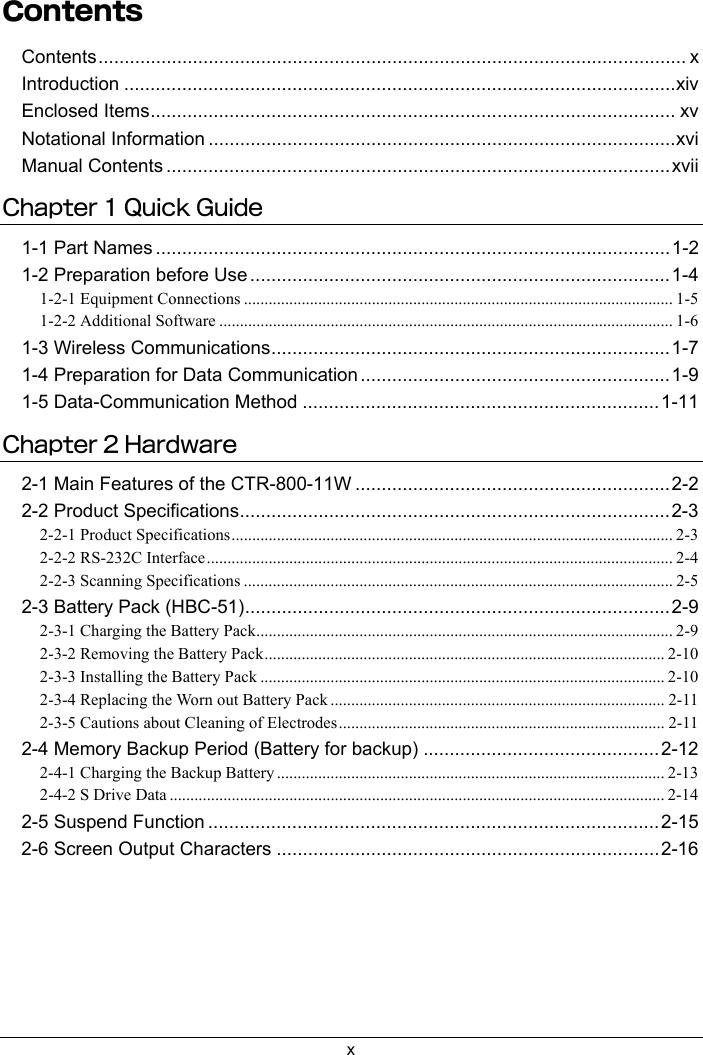
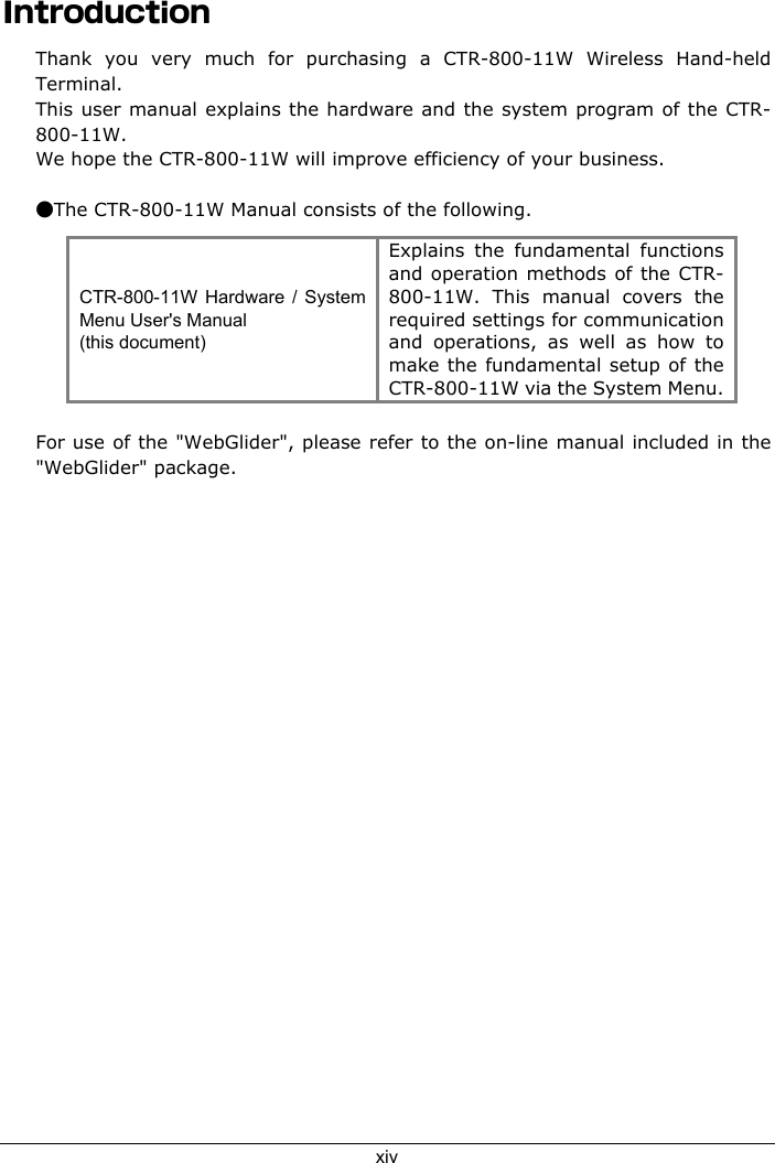


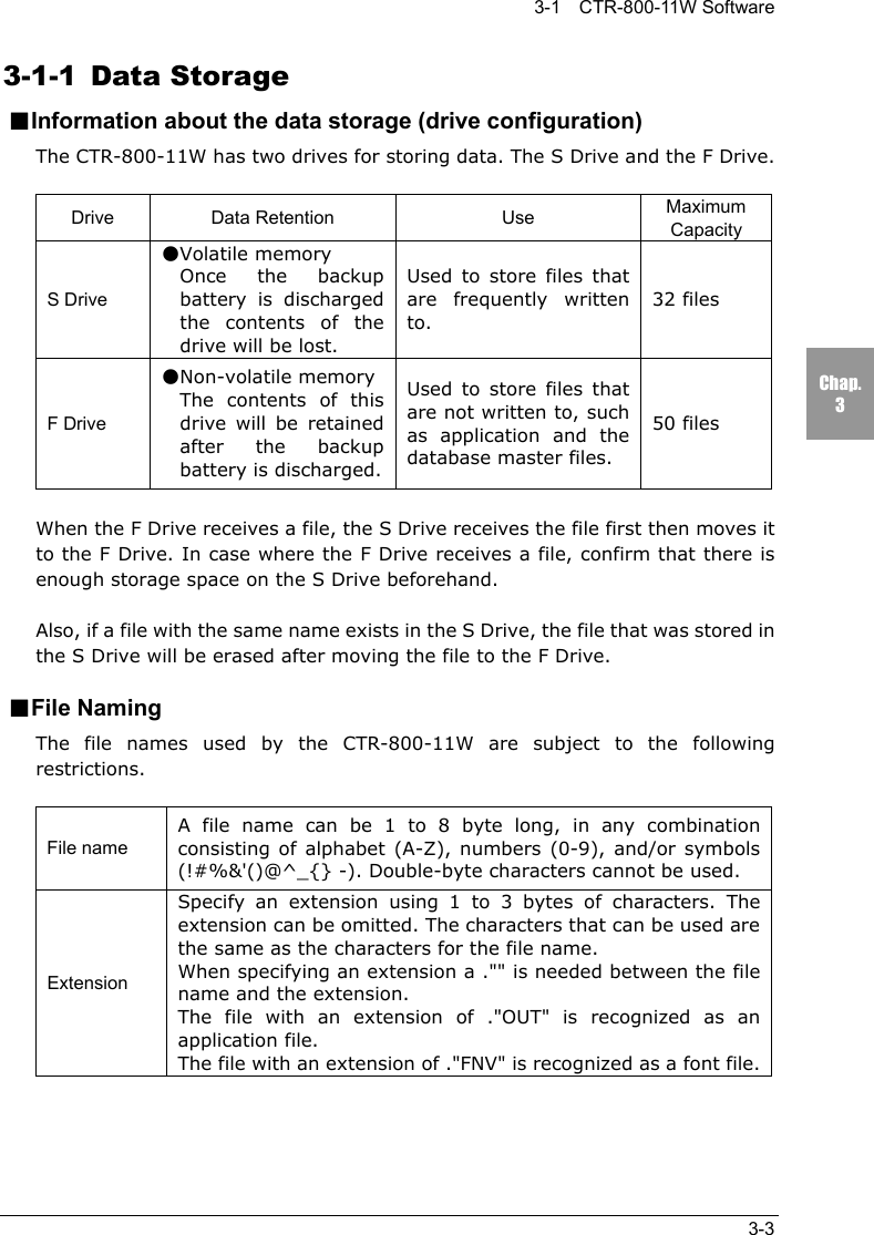

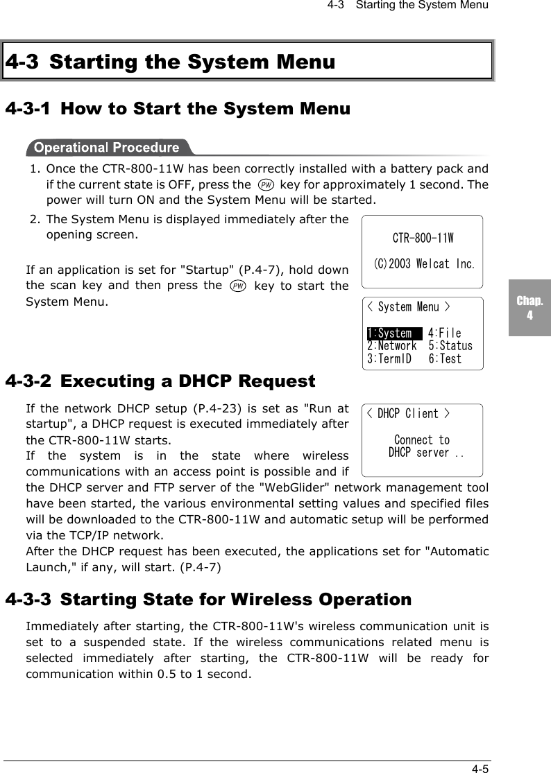
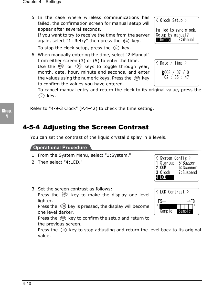
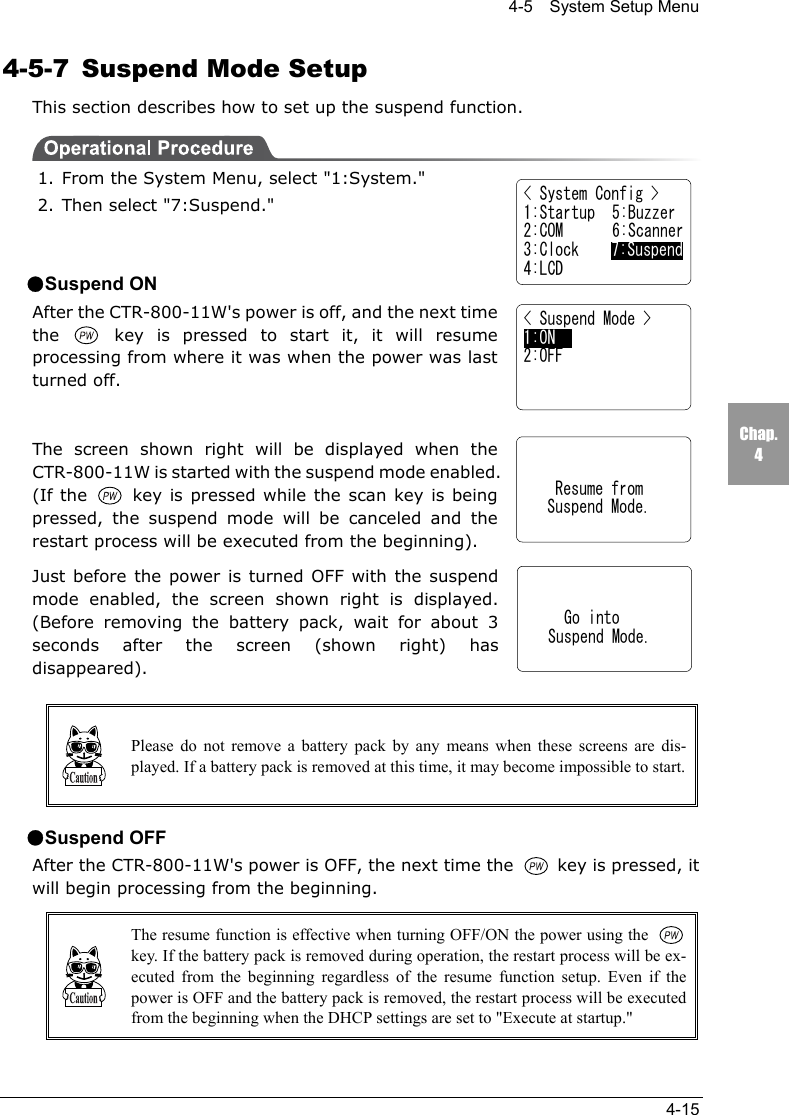
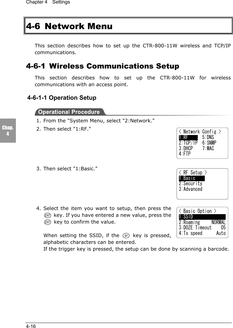
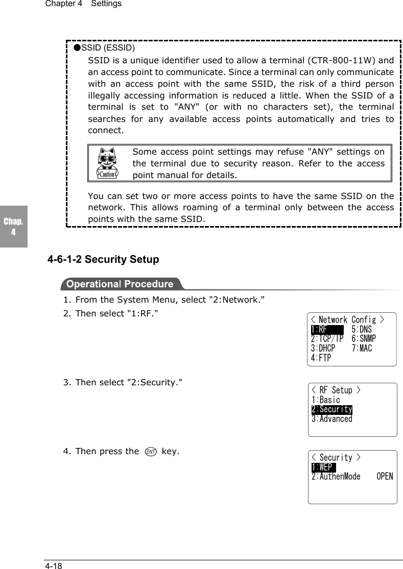
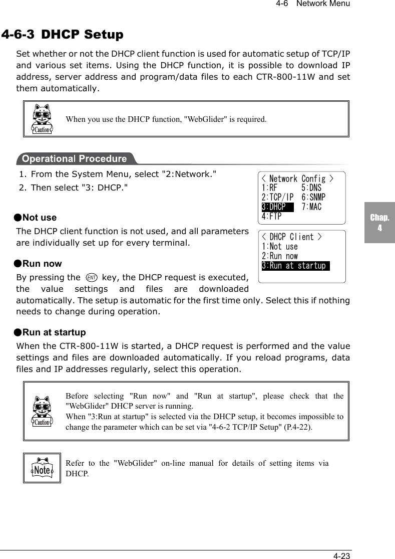
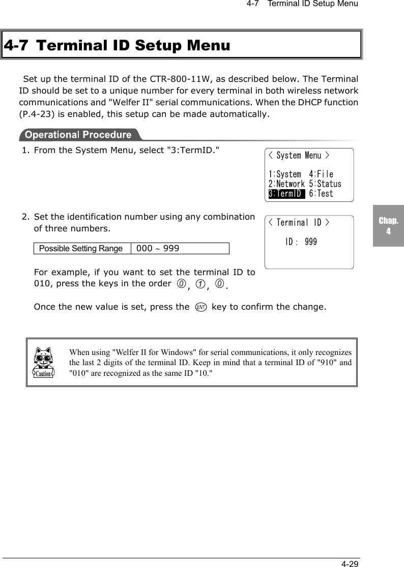
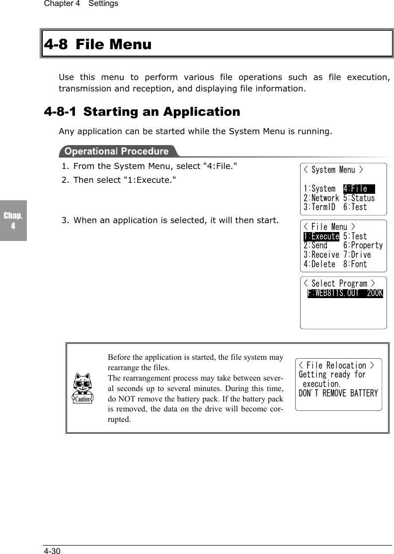
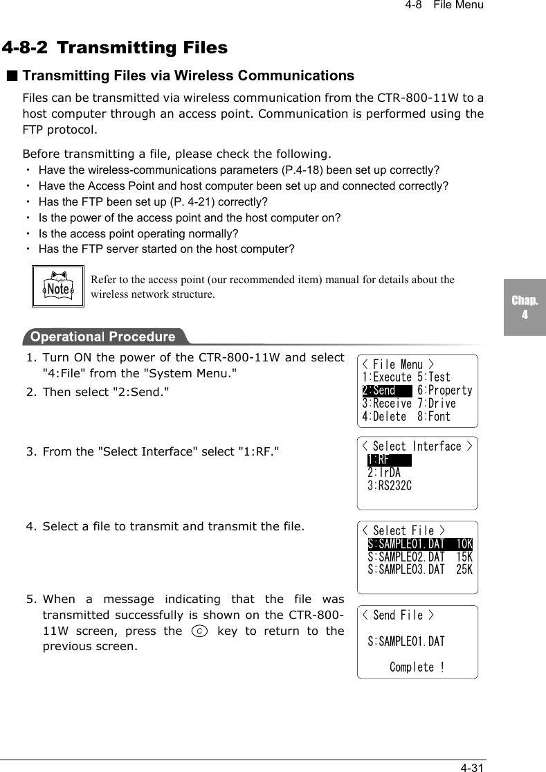
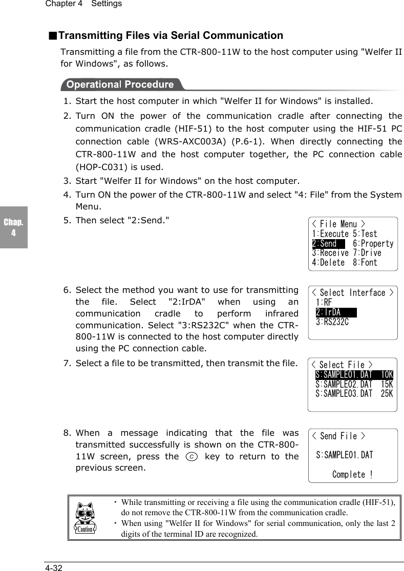
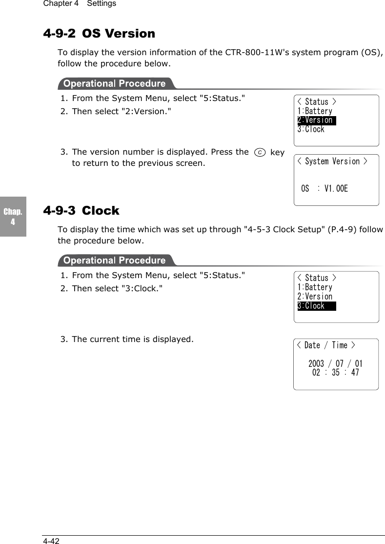
![Chapter 4 Settings4-4Chap.4■About the screen displayDepending on the menu (screen) displayed, the characters "F:~" or "S:~" maybe displayed on the left-hand side of an item. If these characters are displayed onthe left-hand side of an item, they represent the following: "F" = "F Drive" and"S" = "S Drive."When all of the menu items cannot be displayed in onescreen, [↑] (when menu items are hidden above thescreen) or [↓] (when menu items are hidden below thescreen) is displayed on the left-hand side of a screen. Ifthe cursor is moved to a hidden menu item, the screenwill scroll automatically.■Setting the IP address, etc.The IP address etc, is set in form of "000.000.000.000." When you change avalue, move the cursor to the part you want to change, and overwrite with thenew value.The key and the key cannot be used to modify the values.If entering values less than 3 digits in length, the remaining digits have to be 0,for example "001."< Startup Program > F:SAMPLE1.OUT 35K F:SAMPLE2.OUT 35K F:SAMPLE3.OUT 35K↓F:SAMPLE4.OUT 35K](https://usermanual.wiki/Welcat/CTR80011W/User-Guide-353337-Page-57.png)
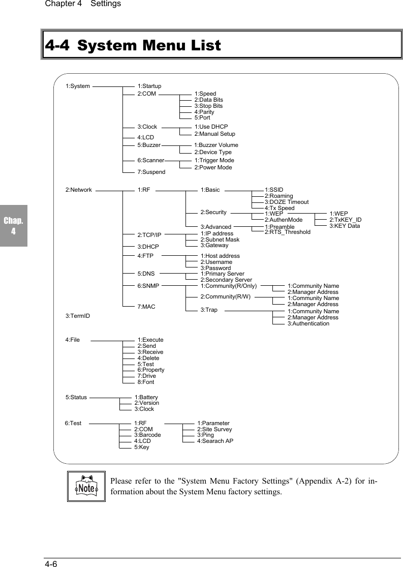
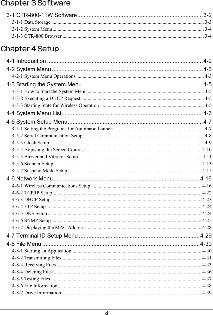
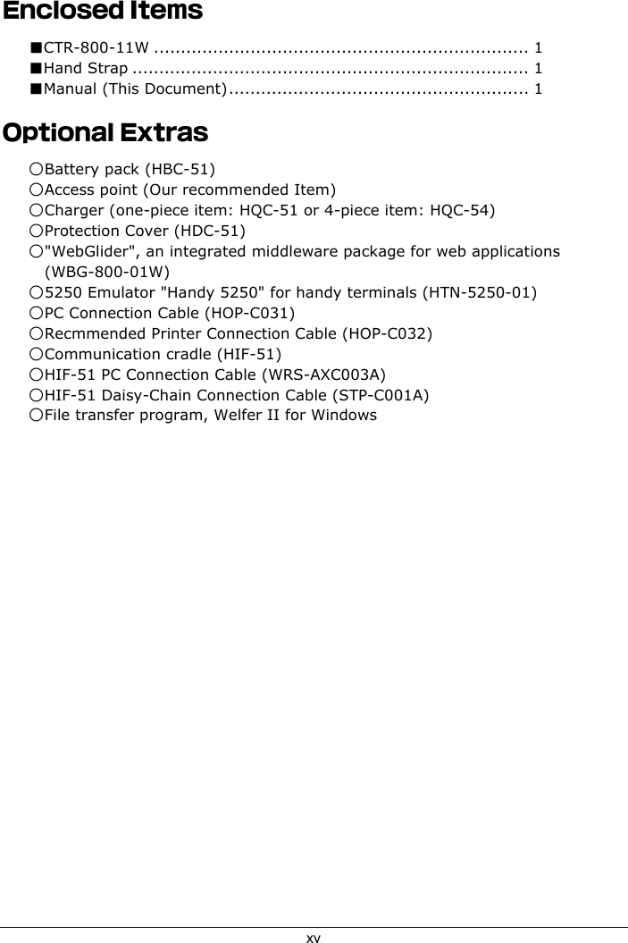
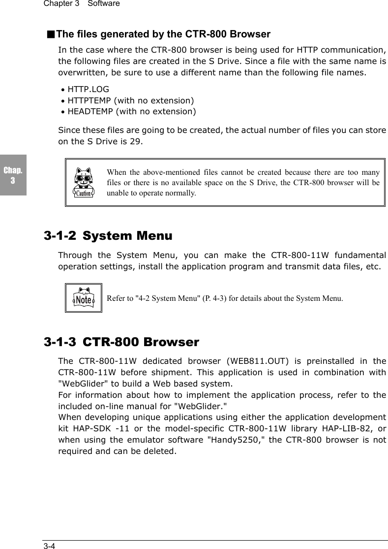
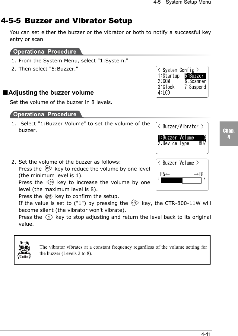
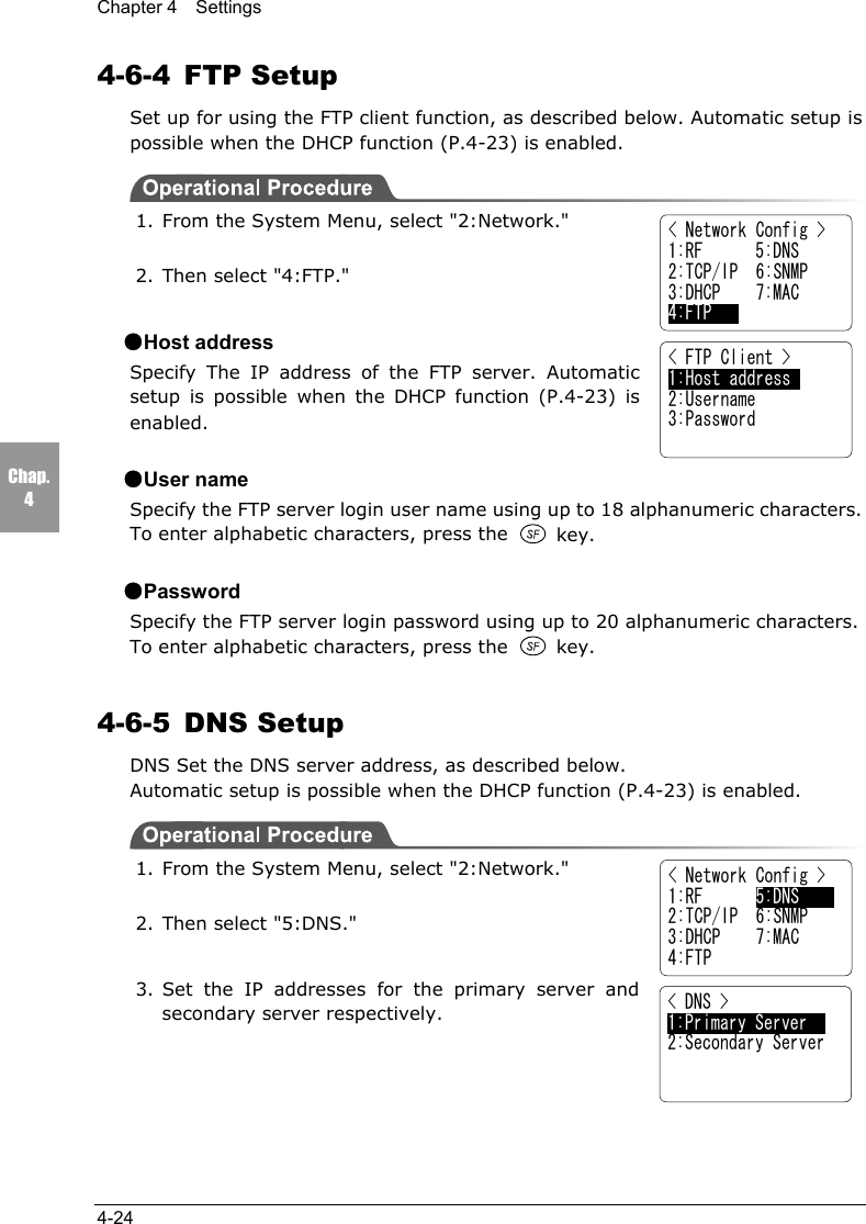
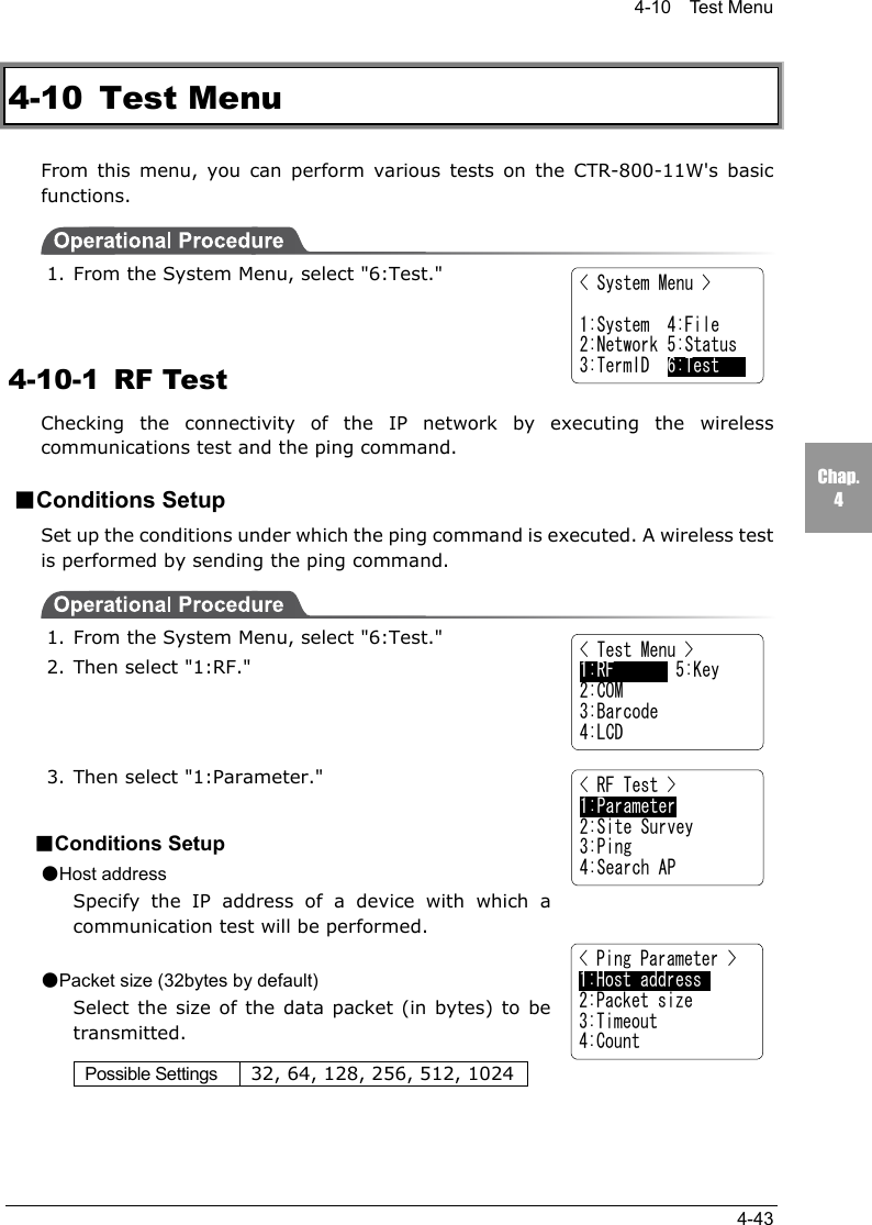
![4-5 System Setup Menu4-7Chap.44-5 System Setup Menu4-5-1 Setting the Programs for Automatic LaunchYou can set programs to launch automatically when the power is turned ON. Inthe factory settings, the System Menu is set to launch automatically.When the DHCP function (P.4-23) is enabled, these settings can be madeautomatically.1. From the System Menu, select "1:System."2. Then select "1:Startup."3. Select "1:System Menu" or "2: User Program." Thecurrent program names are displayed on the bottomline.4. If "1:System Menu" is selected, the System Menuwill be set to launch automatically immediately afterthe power is turned ON.If "2:User Program" is selected, a list of currentlyinstalled applications is displayed. From this list,select an application.5. Once an application is selected, the name of the application will be displayedon the bottom line of the screen.■When no application is storedWhen there are no applications stored, the message "File not found" will bedisplayed. Press the key to go back to the previous screen.< System Menu >1:System 4:File2:Network 5:Status3:TermID 6:Test< System Config >1:Startup 5:Buzzer2:COM 6:Scanner3:Clock 7:Suspend4:LCD< Startup Program >1:System Menu 2:User Program[System Menu]< Startup Program > F:WEB811S.OUT 200K](https://usermanual.wiki/Welcat/CTR80011W/User-Guide-353337-Page-60.png)
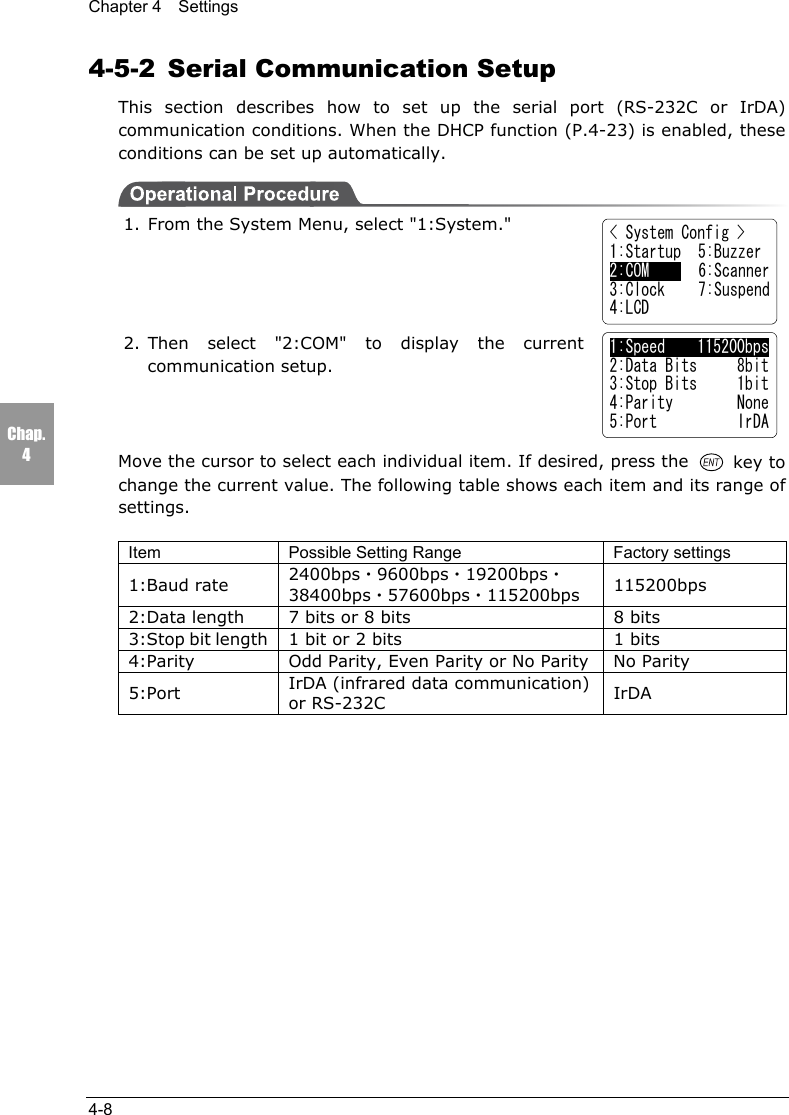
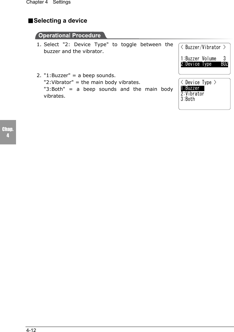
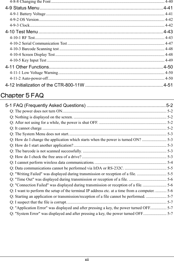
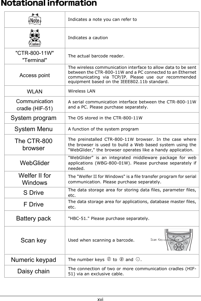
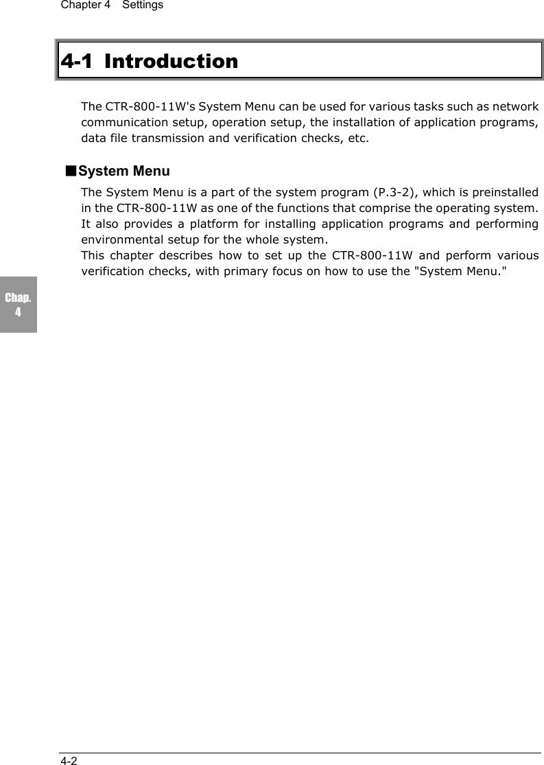
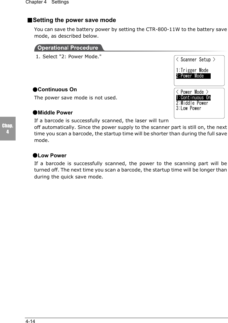
![4-5 System Setup Menu4-13Chap.44-5-6 Scanner SetupSet up the operating conditions for the laser scanner while the applicationprogram is running.1. From the System Menu, select "1:System."2. Then select "6:Scanner."■Setting the trigger modeSet the mode in which the scanning key operates.1. Select "1:Trigger Mode."●Normal ModeWhen the scan key is pressed, the laser turns on andscanning can be performed anytime.●Duplex ModeWhen the scan key is pressed, the laser will flash. If the scan key is pressed again,the laser will turn on and scanning will start.●Release ModeWhen the scan key is pressed, the laser will flash. If the scan key is then released,the light will turn on and scanning will start.■Setting the laser irradiation timeAfter setting the trigger mode, set the laser irradiationtime.Set the value in the range between 0 and 65536 seconds.The laser is turned off when a barcode is not scannedsuccessfully within the specified time.The laser remains on when this value is set to 0 seconds.< System Config >1:Startup 5:Buzzer2:COM 6:Scanner3:Clock 7:Suspend4:LCD< Scanner Setup > 1:Trigger Mode2:Power Mode< Trigger Mode >1:Normal Mode2:Duplex Mode3:Release Mode< Laser On Time > [ 00020 sec.]](https://usermanual.wiki/Welcat/CTR80011W/User-Guide-353337-Page-66.png)
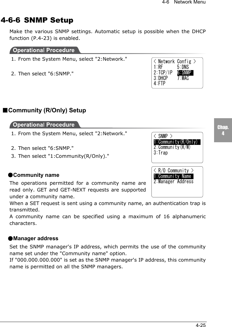
![4-6 Network Menu4-27Chap.4●AuthenticationSet the action of authentication trap to either "send" or "don't send" when accessis recognized except from the community name and SNMP manager's IP addressset in "1: Community (R/Only)" and "2: Community (R/W)."This Trap is sent to the SNMP manager which is set in "2:Target address."■About SNMP・The CTR-800-11W can be managed by using Our "WebGlider" (WBG-800-01W).・SNMP-PDU(Protocol Data Unit)conforms to SNMPv1.・The CTR-800-11W manages the following various MIB group objects.However, because of the CTR-800-11W's functionality, non-supportedobjects are included in the following group.[1.3.6.1.2.1.1] MIB2-System[1.3.6.1.2.1.2] MIB2-Interfaces[1.3.6.1.2.1.4] MIB2-IP *1[1.3.6.1.2.1.5] MIB2-ICMP *1[1.3.6.1.2.1.6] MIB2-TCP[1.3.6.1.2.1.7] MIB2-UDP[1.3.6.1.2.1.11] MIB2-SNMP *1[1.3.6.1.4.1.12392] Welcat Enterprise MIB*1 Non-supported objects are included due tothe functional reason of the CTR-800-11W.Welcat Enterprise MIB is described in ASN.1format.Welcat Enterprise MIB is included in theoptional "WebGlider" (for details, pleasecontact our sales department).](https://usermanual.wiki/Welcat/CTR80011W/User-Guide-353337-Page-80.png)
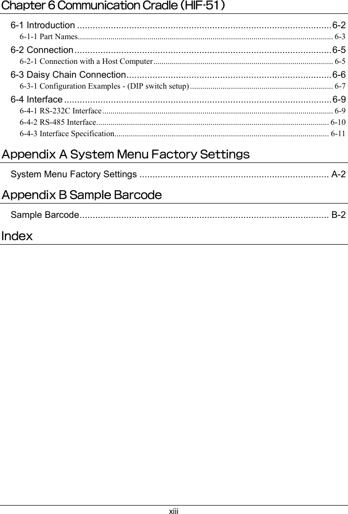
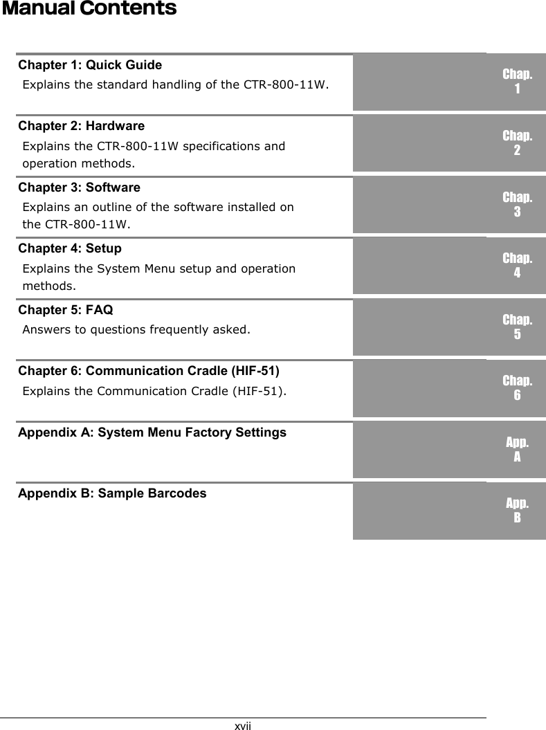
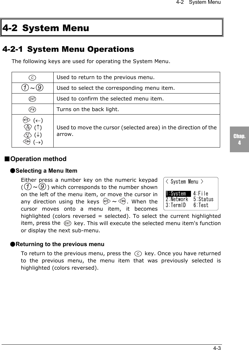
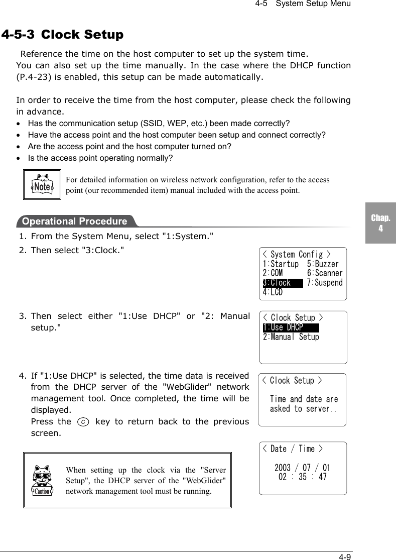
![Chapter 4 Settings4-28Chap.4●Supported TrapsCold Start Transmitted after MIB is initialized and the communicationsstarts. MIB is initialized when the CTR-800-11W has beenturned ON using the PW key. Note that MIB is not initializedwhen the CTR-800-11W has been turned ON in the resumemode.Warm Start Transmitted when communication starts except Cold Start.*2Link up Transmitted when CTR-800-11W synchronizes with anaccess point. However, a Link Up is not transmitted whenthe CTR-800-11W synchronizes with an access point for thefirst time (When a Cold Start or a Warm Start istransmitted). When the CTR-800-11W newly enters aservice area of an access point and synchronizes, or when itsynchronizes with a new access point while roaming, a LinkUp is transmitted (in the same timing as signalSIGRFU_INSYNC).Link down Transmitted when the communication ends. However, it isnot transmitted when the CTR-800-11W is outside theservice area of an access point.Authentication Transmitted when a third person tries to access the CTR-800-11W with an invalid community. This authenticationtrap is sent to the IP address set through the System Menu"Trap Manager IP address" (P.4-26). However, this istransmitted only when the value "send" is set through theSystem Menu "Illegal access Trap" (P.4-27).*2 MIB is not initialized even if the "CTR-800-11W" setup corresponding to MIB (IPaddress, subnet mask, default gateway, etc.) has been changed. In this case, aWarm Start is transmitted instead of a Cold Start.When initializing MIB, cancel the resume mode then turn ON the power.4-6-7 Displaying the MAC Address You can display the MAC address (unique hardware address) of the CTR-800-11W. This address cannot be changed.1. From the System Menu, select "2:Network."2. Then select "7:MAC."< Network Config >1:RF 5:DNS2:TCP/IP 6:SNMP3:DHCP 7:MAC4:FTP< MAC address > [00C0740208D5]](https://usermanual.wiki/Welcat/CTR80011W/User-Guide-353337-Page-81.png)
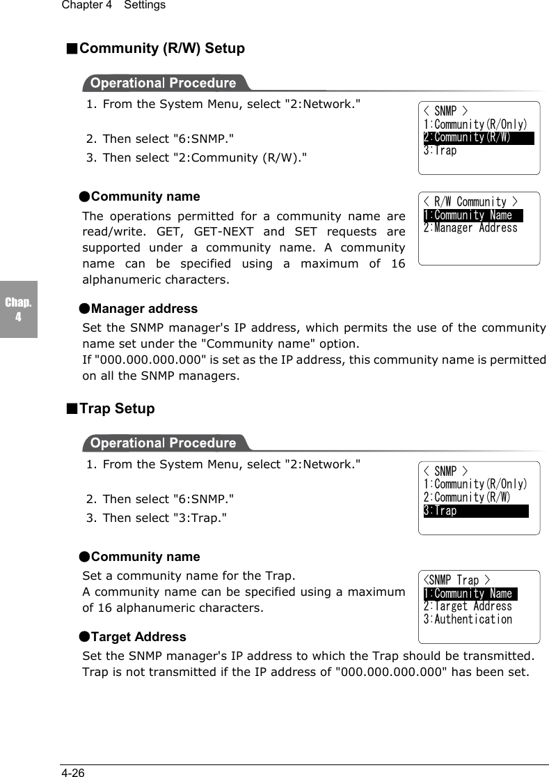
![Chapter 4 Settings4-40Chap.44-8-8 Changing the FontIf font files are installed, the font used in an application can be changed.The font used for the System Menu cannot be changed. Only systemt Gothic (12-dot display) can be used.1. From the System Menu, select "4:File."2. Select "8:Font."3. The current font name is displayed on the bottomline. "1:System Gothic" is the font used for theSystem Menu.4. To change the current font, select "2:Optional Font"to display a list of font files. For example, if the 16-dot Gothic font provided in the CTR-800-11Wmodel-specific library (HAP-LIB-82, optional) isloaded, it becomes possible to display 16 -dot fonts.When using an additional font, the application mustsupport the font. In the case where an application does not support theselected font, the application may not work or the screen display may bedistorted.The extension of a font file is "FNV."When supplied, the CTR-800-11W does not have any font files (~.FNV). Whenyou change the font, first download 16-dot Gothic font, etc. included in the CTR-800-11W model-specific library (HAP-LIB-82, optional) to the F Drive.< File Menu >1:Execute 5:Test2:Send 6:Property3:Receive 7:Drive4:Delete 8:Font< Select Font >1:System Gothic2:Optional Font[System Gothic]](https://usermanual.wiki/Welcat/CTR80011W/User-Guide-353337-Page-93.png)
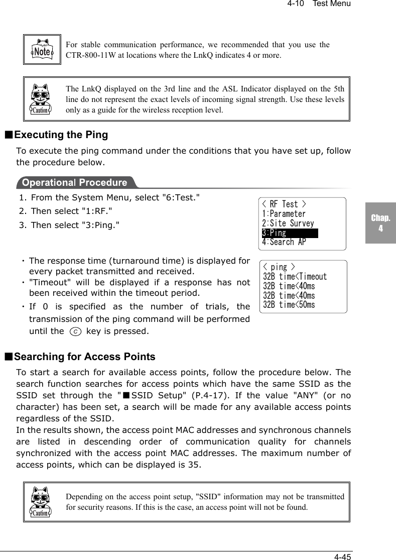
![Chapter 4 Settings4-44Chap.432B time<30msAP_MAC[001122334455]LnkQ L HCH:01 SPD: 1MbpsASL L H●Timeout Period (1 second by default)Set the Timeout period in seconds.Possible Setting Range 1 ∼ 255 seconds●Number of Attempts (4 by default)Set the number of attempts that can be made at transmitting the ping.Possible Setting Range 0 ∼ 255 timesIf 0 is specified, transmission of the ping command will continue until the key is pressed.■RF TestPerform a wireless test by executing the ping command. The ping command willbe continually transmitted to the host IP address set in "Setup Conditions."During a wireless test, the result of the ping command, synchronized accesspoint's MAC Address, the wireless reception level (ASL), the communicationquality (LnkQ), the channel used and transmission speed are displayed.1. From the System Menu, select "6:Test."2. Then select "1:RF."3. Then select "2:Site Survey."4. The wireless communications test screen isdisplayed and the ping communication begins.The 1st line displays the result of the ping command.The 2nd line displays the MAC address of the accesspoint used for wireless communications.The 3rd line displays the LnkQ indicator showing thequality of communication with the access point.The 4th line displays the synchronized channel and the transmission speed.The 5th line displays the ASL indicator showing the level of incoming signalstrength from the access point.To cancel, press the key.< Test Menu >1:RF 5:Key2:COM3:Barcode4:LCD< RF Test >1:Parameter2:Site Survey3:Ping4:Search AP](https://usermanual.wiki/Welcat/CTR80011W/User-Guide-353337-Page-97.png)
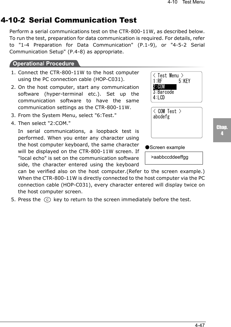
![Chapter 4 Settings4-46Chap.4< Test Menu >1:RF 5:Key2:COM3:Barcode4:LCD< RF Test >1:Parameter2:Site Survey3:Ping4:Serarch AP< Search AP > Target SSID =ANYSearch Access Ponit..< AP Search Result > 00A0F850D7D3 01 00A0F850D7F4 06 00A0F850D7CE 11< AP Property >MAC[00A0F850D7D3]SSID = 800111:Survey 2:Select1. From the System Menu, select "6:Test."2. Then select "1:RF."3. Then select "4:Search AP."4. A search for access points will be started. The SSIDthat has been set through the "■SSID Setup" (P.4-17) is displayed on the lines 3 and 4 on the screen,and an access point with the same SSID setup will besearched. If the value "ANY" (or no character) hasbeen set, any available access point will be searchedregardless of the SSID.5. The access point search results are displayed. In theresults shown, the access point MAC addresses andsynchronous channels are listed in descending orderof communication quality. Once an access point isselected from the search results, the SSID of thataccess point can be obtained. A wireless test can beperformed with the access point only.Press the key to return to 3.6. The SSID of the selected access point is displayed(the SSID in the image shown right is "80011").Select "1:RF" to initiate a wireless test with theselected access point only. To perform this test, the"■Conditions Setup" (P.4-43) must have beencompleted.Selecting "2:Select" will set up the SSID with the character string displayedhere.](https://usermanual.wiki/Welcat/CTR80011W/User-Guide-353337-Page-99.png)
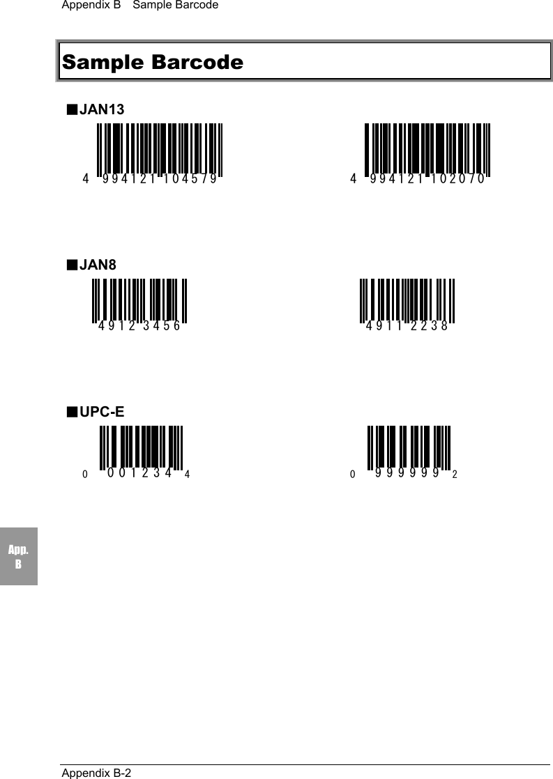
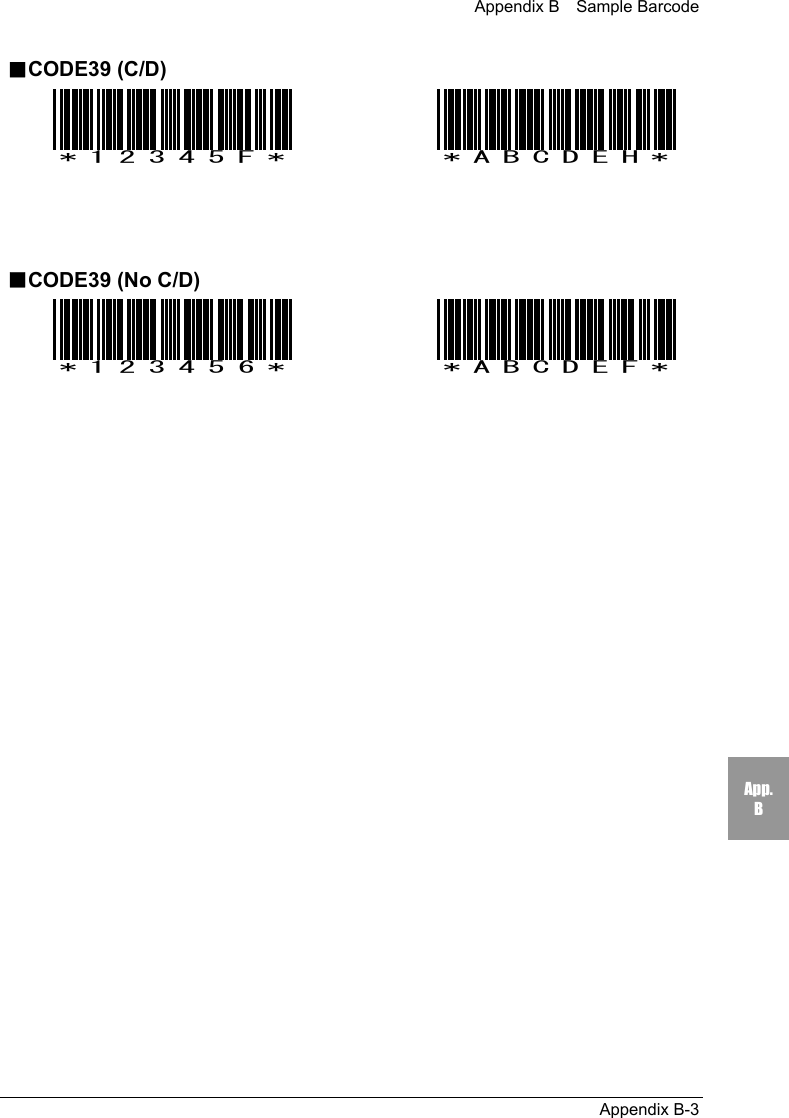
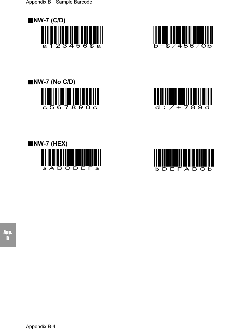
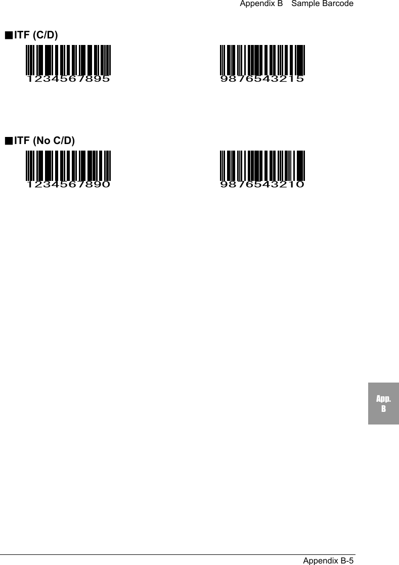
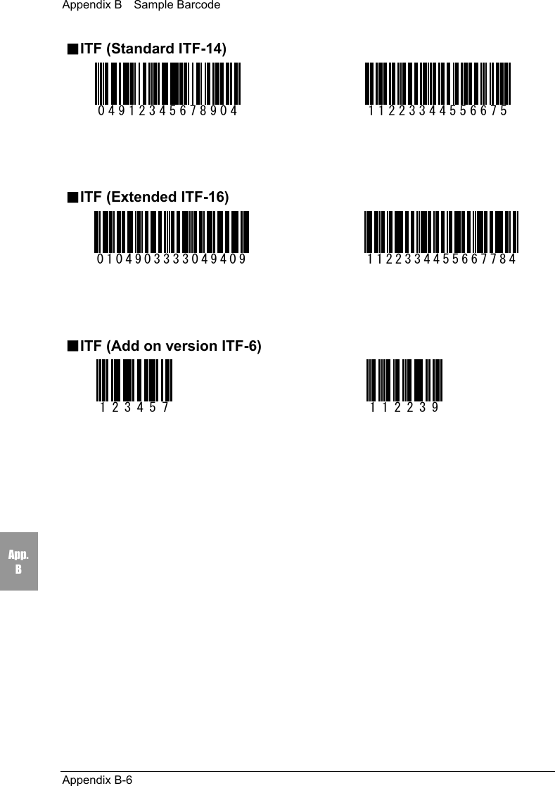
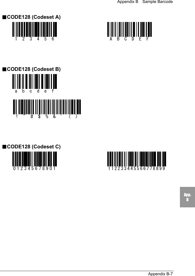
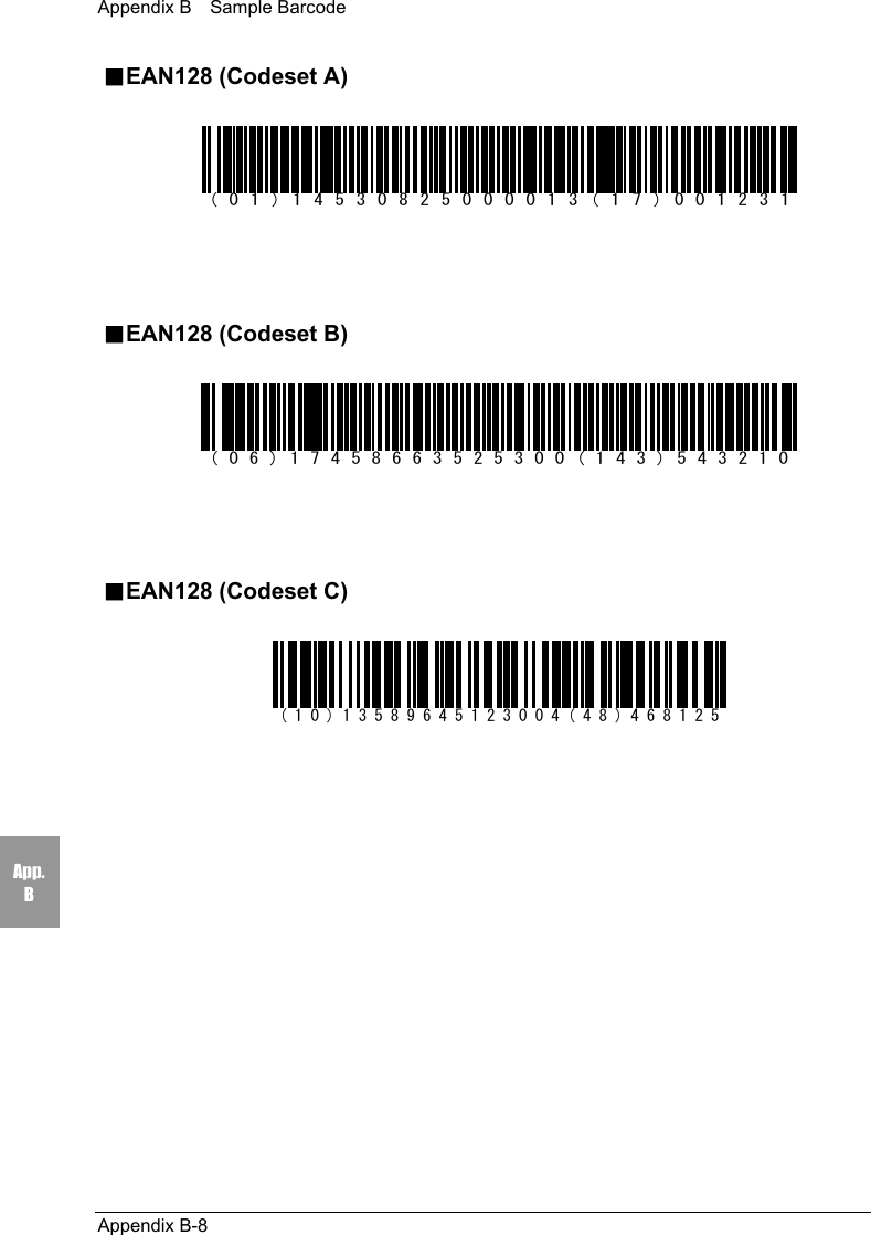
![Chapter 4 Settings4-48Chap.44-10-3 Barcode Scanning testPerform a barcode scanning test, as described below. A sample barcode can befound in "Sample Barcode" (Appendix B-2).1. From the System Menu, select "6:Test."2. Then select "3:Barcode."3. Press the scan key to scan the barcode. The scanresult is displayed on the screen, similar to theimage shown right.The scanned barcode is displayed on the 2nd line.The type and the number of digits of the scannedbarcode are displayed on the bottom line. If you holddown the scan key for approximately 1 second, the continuous scanningmode will be enabled. Scanning will continue until you release the scan key,and the success rate will be displayed in the bottom right of the screen.If the trigger mode or the power save mode is set, it will not affect thecontinuous scanning.4-10-4 Screen Display TestPerform a screen display test, as described below.1. From the System Menu, select "6:Test."2. Then select "4:LCD"3. The backlight is turned ON and the whole screen isfilled in. If any keys are pressed, the corresponding characters will bedisplayed on the screen in sequence. If the scan key is pressed, the test willstop with the screen displaying where the test stopped. The test will resumeif the scan key is pressed again. If the key is pressed, the test will beaborted and the CTR-800-11W will return to the screen immediately beforethe test.< Barcode Test >4994121104579JAN13 L:13 100% 、。,.・:;?!゛゜´`¨^ ̄_ヽヾゝゞ〃仝々〆〇ー―‐/\~∥|…‥‘’“”()〔〕[]{}〈こごさざしじすずせぜそぞただちぢっつづてでとどなにぬねのはばぱひびぴふぶぷへべぺほぼぽまみむめもゃや……< Test Menu >1:RF 5:KEY2:COM3:Barcode 4:LCD< Test Menu >1:RF 5:KEY2:COM3:Barcode4:LCD](https://usermanual.wiki/Welcat/CTR80011W/User-Guide-353337-Page-101.png)
![Chapter 4 Settings4-50Chap.44-11 Other Functions4-11-1 Low Voltage WarningIf the voltage level of the equipped battery pack decreases, it becomesimpossible to perform the following operations with the System Menu.・Launch of applications・File transmission, reception, deletion and test・Clock setupIf any of the operations mentioned above is performedwhen the voltage level of the battery pack is low, thescreen, similar to the image shown right, will bedisplayed.At this time, [Battery Low] is displayed on the 2nd line ofthe screen, and CTR-800-11W will beep 3 times forwarning.Even if the voltage level of the battery pack is low,operations of the System Menu other than those abovecan be performed.Also, when the CTR-800-11W judges that the voltage level is less than theregulation level, it displays a message on the screen, shown right, for 5 secondswhile sounding short beeps, and then shuts down automatically.4-11-2 Auto-power-offThrough the System Menu, if no key operation is performed for approximately 10minutes, the power shuts off automatically.This function may also be incorporated into an application. Refer to the applica-tions manual for details.[ Batterey Low ]Change battery pack!< File Menu > [ Battery Low ]You can't finishthis operation.Change battery pack!](https://usermanual.wiki/Welcat/CTR80011W/User-Guide-353337-Page-103.png)