Welcat CTR80011W Wireless Hand-held Terminal User Manual manual
Welcat, Inc. Wireless Hand-held Terminal manual
Welcat >
manual

i
Copyright 2003 Welcat Inc. All rights reserved.
This document may not be reproduced whole or in part without prior consent from
the publisher.
Specifications are subject to change without prior notice.
All products and company names mentioned in this manual are the trademarks or
registered trademarks of their respective owners.

ii
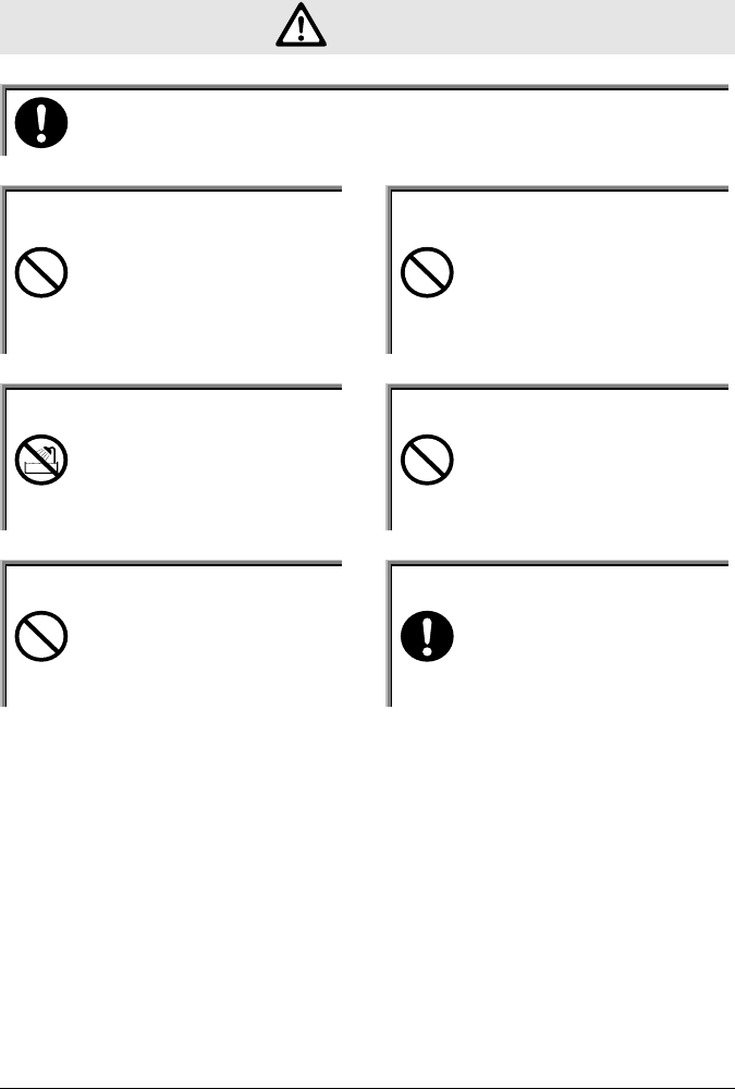
SAFETY PRECAUTIONS
•Be sure to read these precautions before using this product in order to insure safe
operation of the equipment.
•Keep this User's Manual on hand for future reference whenever you may need it.
Strict observance of these warning and caution indications are a MUST for preventing
accidents which could result in bodily injury and substantial property damage. Make
sure you fully understand all definitions of these terms and related symbols given below,
before you proceed to the text itself.
Warning This symbol indicates an item that can result in death or serious
personal injury if ignored.
Caution This symbol indicates an item that can result in serious personal
injury or material damage if ignored.
Meaning of Symbols
A trian
g
le inside indicates somethin
g
y
ou should be careful
about.
A dia
g
onal line throu
g
h a circle indicates somethin
g
y
ou should
not do.
A black circle indicates something you must do.

iii
WARNING
Only use the specified bat-
tery pack.
Using a different type of battery
pack could cause damage to
equipment, battery-rupture or
leakage of battery fluid and re-
sulting in a fire, burn, bodily in-
jury, or serious damage to prop-
erty.
Only use the specified charger
for charging the battery pack.
Using a different type of charger
could cause battery-rupture or
leakage of battery fluid and re-
sulting in a fire, burn, bodily in-
jury, or serious damage to prop-
erty.
Only use the specified AC
adaptor for Communication
Cradle HIF-51.
Using a different type of AC
adaptor could cause heat or fire,
or damage to equipment.
Do not heat the battery pack,
nor put it into fire or water.
Doing so could cause battery-
rupture or leakage of battery fluid
and resulting in a fire, burn,
bodily injury, or serious damage
to property.
Do not attempt disassemble
or modify the battery.
Doing so could cause battery-
rupture or leakage of battery fluid
and resulting in a fire, burn,
bodily injury, or serious damage
to property.
Do not carry or store the
battery pack together with
metallic object such as ball-
point pens, necklaces, coins,
hairpins, etc.
Doing so could short-circuit the
terminal pins, causing the batteri-
es to rupture the battery fluid to
leak, resulting in a fire, burn,
bodily injury.
Do not use the battery if
leakage, change of color or
shape, or other abnormalities
occur.
Doing so could cause fire, burn,
bodily injury, or serious damage
to property. If it brings close to
fire, this cause ignition in leakage
of battery fluid.
Avoid dropping the battery
pack or letting it undergo any
shock or impact.
Doing so could cause the batteri-
es to break, generate heat, rupture
or burn.

iv
Do not charge the battery
pack where any inflammable
gases may be emitted.
Doing so could cause battery-
rupture or leakage of battery fluid
and resulting in a fire, burn,
bodily injury, or serious damage
to property.
If battery fluid gets in your
eyes, wash it out with clean
water and contact a physi-
cian immediately.
If it is left, there is fear of loss of
eyesight.
If battery fluid gets on your
skin, or clothes, wash it off
with clean water.
If it is left, there is fear of dam-
age of skin.
Do not attempt disassemble
or modify the battery charger
and the communication cra-
dle.
Doing so could cause excessive
heat, fire, or electrical shock.
Never cut, damage or modify
the power code of battery
charger and communication
cradle.
Doing so could cause excessive
heat, fire, or electrical shock.
Do not place or charge the
battery in the hot places such
as a fire side, a stove side,
under the burning sun, etc.
Doing so could cause battery-
rupture or leakage of battery fluid
and resulting in a fire, burn,
bodily injury, or serious damage
If there are problems or ab-
normalities, such as emitting
smoke or strange odor found
with communication cradles,
turn off the power and unplug
the AC power code.
Continued use in this condition
could cause fire or electrical
shock.
Do not stare into laser beam.
Do not aim the laser at a
person's eye.
The laser beam emitted through
the reading window is harmful to
the eyes.
Be careful not to hook a
strap when carrying the ter-
minal.
If strap is caught in an obstacle, it
could cause injury or accident.
v
Caution
Only use the specified serial cable for Communication Cradle HIF-51.
Using a different type of cable could cause communication error or equipment trouble.
Do not place or use the ter-
minal in the hot places such
as a fire side, a stove side,
under the burning sun, etc.
Doing so could cause fire, modi-
fication of a case or equipment
trouble.
Do not place or use the ter-
minal in high humid or dusty
areas.
If moisture or dust will get into
the terminal, resulting in failure,
fire or electrical shock.
Do not use the terminal in
the place of water, such as
rain or shower.
If water will gets into the termi-
nal, resulting in failure, fire or
electrical shock.
Do not drop the terminal or
subject it to strong impact or
vibrations.
This could cause malfunction or
failure.
Do cover or wrap up the
equipment or AC adapter in
a cloth or blanket.
Doing so could cause the unit to
heat up inside, defouming its
housing, resulting in a fire.
Keep the power cord away
from any heating equipment.
Failure to do so could melt the
sheathing, resulting in a fire or
electrical shock.

vi
Laser Safety
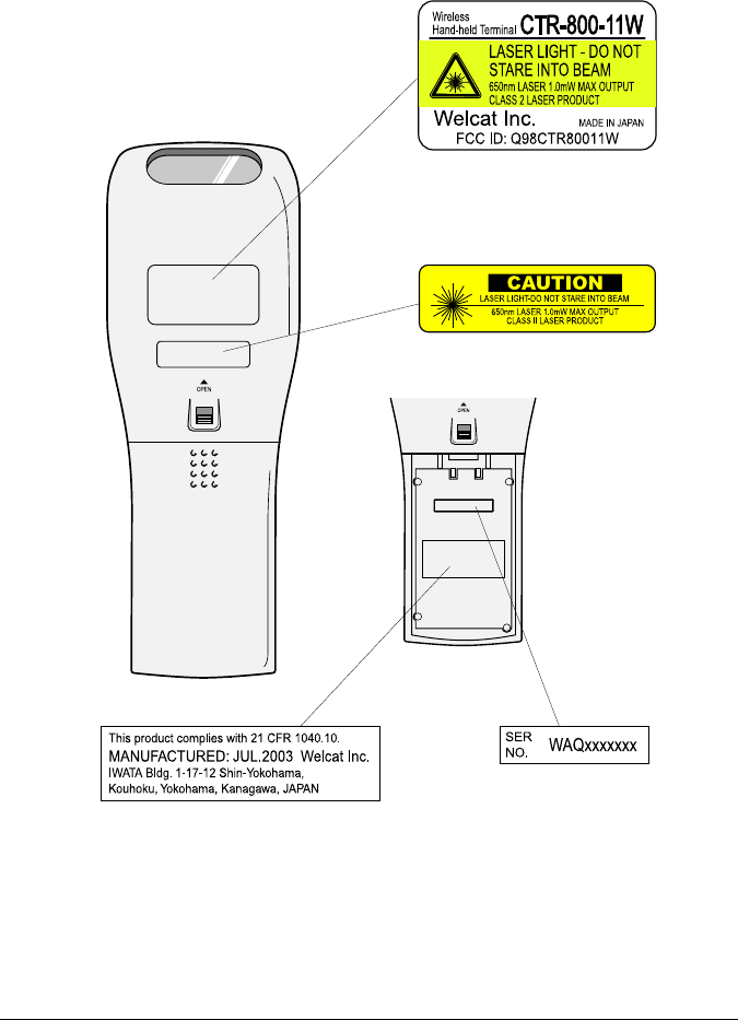
This product using the laser comply with US 21CFR1040.10.
This equipment is certified as a Class 2 laser product under the U.S. Department of
Health and Human Services (DHHS) Radiation Performance Standard according to the
Radiation Control for Health and Safety Act of 1968. This means that the equipment
does not produce hazardous laser radiation.
FDA Regulations
U.S. Food and Drug Administration (FDA) has implemented regulations for laser pro-
ducts manufactured on and after August 2, 1976. Compliance is mandatory for products
marketed in the United States. The labels on the product indicate compliance with the
FDA regulations and must be attached to laser products marketed in the United States.
Caution:
Do not look into the laser beam source through the reading window or point the
reading window towards the eyes. The laser beam emitted through the reading win-
dow is harmful to the eyes.
Use of controls, adjustments or performance of procedures other than those specified
in this manual may result in hazardous invisible radiation exposure.
Class 2 laser scanners use a low power, visible light diode. As with any very bright
light source, such as the sun, the user should avoid staring directly into the light beam.
Momentary exposure to a Class 2 laser is not known to be harmful.
vii
Product Labeling

viii
FCC Statement
This Device complies with part 15 of the FCC Rules.
Operation is subject to the following two conditions:
(1) This device may not cause harmful interference, and
(2) This device must accept any interference received, including interfer-
ence that may cause undesired operation.
Note:
This equipment has been tested and found to comply with the limits for a Class B
digital device, pursuant to part 15 of the FCC Rules. These limits are designed to
provide reasonable protection against harmful interference in a residential installation.
This equipment generates, uses and can radiate radio frequency energy and, if not in-
stalled and used in accordance with the instructions, may cause harmful interference to
radio communications. However, there is no guarantee that interference will not occur in
a particular installation. If this equipment does cause harmful interference to radio or
television reception, which can be determined by turning the equipment off and on, the
user is encouraged to try to correct the interference by one or more of the following
measures:
•Reorient or relocate the receiving antenna.
•Increase the separation between the equipment and receiver.
•Connect the equipment into an outlet on a circuit different from that to which the
receiver is connected.
•Consult the dealer or an experienced radio/TV technician for help.
Warning:
Changes or modifications not expressly approved by the manufacturer responsible for
compliance could void the user's authority to operate the equipment.

ix
FCC Radiation Exposure Statement
The available scientific evidence does not show that any health problems are associated
with using low power wireless devices. There is no proof, however, that these low pow-
er wireless devices are absolutely safe. Low power Wireless devices emit low levels of
radio frequency energy (RF) in the microwave range while being used. Whereas high
levels of RF can produce health effects (by heating tissue), exposure to low level RF that
does not produce heating effects causes no known adverse health effects. Many studies
of low level RF exposures have not found any biological effects. Some studies have
suggested that some biological effects might occur, but such findings have not been con-
firmed by additional research. The CTR-800-11W has been tested and found to comply
with the Federal Communications Commission (FCC) guidelines on radilo frequency
energy (RF) exposures. The maximum SAR levels tested for the CTR-800-11W has
been shown to be 1.02 W/kg at body.

x
Contents
Contents................................................................................................................ x
Introduction .........................................................................................................xiv
Enclosed Items.................................................................................................... xv
Notational Information .........................................................................................xvi
Manual Contents ................................................................................................xvii
Chapter 1 Quick Guide
1-1 Part Names ..................................................................................................1-2
1-2 Preparation before Use ................................................................................1-4
1-2-1 Equipment Connections ........................................................................................................ 1-5
1-2-2 Additional Software .............................................................................................................. 1-6
1-3 Wireless Communications............................................................................1-7
1-4 Preparation for Data Communication ...........................................................1-9
1-5 Data-Communication Method ....................................................................1-11
Chapter 2 Hardware
2-1 Main Features of the CTR-800-11W ............................................................2-2
2-2 Product Specifications..................................................................................2-3
2-2-1 Product Specifications........................................................................................................... 2-3
2-2-2 RS-232C Interface................................................................................................................. 2-4
2-2-3 Scanning Specifications ........................................................................................................ 2-5
2-3 Battery Pack (HBC-51).................................................................................2-9
2-3-1 Charging the Battery Pack..................................................................................................... 2-9
2-3-2 Removing the Battery Pack.................................................................................................2-10
2-3-3 Installing the Battery Pack .................................................................................................. 2-10
2-3-4 Replacing the Worn out Battery Pack ................................................................................. 2-11
2-3-5 Cautions about Cleaning of Electrodes............................................................................... 2-11
2-4 Memory Backup Period (Battery for backup) .............................................2-12
2-4-1 Charging the Backup Battery .............................................................................................. 2-13
2-4-2 S Drive Data ........................................................................................................................ 2-14
2-5 Suspend Function ......................................................................................2-15
2-6 Screen Output Characters .........................................................................2-16

xi
Chapter 3 Software
3-1 CTR-800-11W Software...............................................................................3-2
3-1-1 Data Storage .......................................................................................................................... 3-3
3-1-2 System Menu......................................................................................................................... 3-4
3-1-3 CTR-800 Browser ................................................................................................................. 3-4
Chapter 4 Setup
4-1 Introduction ..................................................................................................4-2
4-2 System Menu ...............................................................................................4-3
4-2-1 System Menu Operations ...................................................................................................... 4-3
4-3 Starting the System Menu............................................................................4-5
4-3-1 How to Start the System Menu ............................................................................................. 4-5
4-3-2 Executing a DHCP Request ..................................................................................................4-5
4-3-3 Starting State for Wireless Operation ................................................................................... 4-5
4-4 System Menu List.........................................................................................4-6
4-5 System Setup Menu.....................................................................................4-7
4-5-1 Setting the Programs for Automatic Launch ........................................................................ 4-7
4-5-2 Serial Communication Setup................................................................................................. 4-8
4-5-3 Clock Setup ........................................................................................................................... 4-9
4-5-4 Adjusting the Screen Contrast.............................................................................................4-10
4-5-5 Buzzer and Vibrator Setup .................................................................................................. 4-11
4-5-6 Scanner Setup ...................................................................................................................... 4-13
4-5-7 Suspend Mode Setup........................................................................................................... 4-15
4-6 Network Menu............................................................................................4-16
4-6-1 Wireless Communications Setup ........................................................................................ 4-16
4-6-2 TCP/IP Setup ....................................................................................................................... 4-22
4-6-3 DHCP Setup ........................................................................................................................ 4-23
4-6-4 FTP Setup ............................................................................................................................ 4-24
4-6-5 DNS Setup ........................................................................................................................... 4-24
4-6-6 SNMP Setup ........................................................................................................................ 4-25
4-6-7 Displaying the MAC Address ............................................................................................. 4-28
4-7 Terminal ID Setup Menu ............................................................................4-29
4-8 File Menu ...................................................................................................4-30
4-8-1 Starting an Application........................................................................................................ 4-30
4-8-2 Transmitting Files................................................................................................................ 4-31
4-8-3 Receiving Files .................................................................................................................... 4-33
4-8-4 Deleting Files ...................................................................................................................... 4-36
4-8-5 Testing Files......................................................................................................................... 4-37
4-8-6 File Information................................................................................................................... 4-38
4-8-7 Drive Information................................................................................................................ 4-39

xii
4-8-8 Changing the Font ............................................................................................................... 4-40
4-9 Status Menu...............................................................................................4-41
4-9-1 Battery Voltage .................................................................................................................... 4-41
4-9-2 OS Version........................................................................................................................... 4-42
4-9-3 Clock.................................................................................................................................... 4-42
4-10 Test Menu ................................................................................................4-43
4-10-1 RF Test............................................................................................................................... 4-43
4-10-2 Serial Communication Test ............................................................................................... 4-47
4-10-3 Barcode Scanning test ....................................................................................................... 4-48
4-10-4 Screen Display Test ........................................................................................................... 4-48
4-10-5 Key Input Test ................................................................................................................... 4-49
4-11 Other Functions........................................................................................4-50
4-11-1 Low Voltage Warning........................................................................................................ 4-50
4-11-2 Auto-power-off.................................................................................................................. 4-50
4-12 Initialization of the CTR-800-11W ............................................................4-51
Chapter 5 FAQ
5-1 FAQ (Frequently Asked Questions) .............................................................5-2
Q: The power does not turn ON...................................................................................................... 5-2
Q: Nothing is displayed on the screen. ........................................................................................... 5-2
Q: After not using for a while, the power is shut OFF. .................................................................. 5-2
Q: It cannot charge. ......................................................................................................................... 5-2
Q: The System Menu does not start................................................................................................ 5-3
Q: How do I change the application which starts when the power is turned ON? ........................ 5-3
Q: How do I start another application?........................................................................................... 5-3
Q: The barcode is not scanned successfully. .................................................................................. 5-3
Q: How do I check the free area of a drive? ................................................................................... 5-3
Q: I cannot perform wireless data communications. ...................................................................... 5-4
Q: Data communications cannot be performed via IrDA or RS-232C. ......................................... 5-5
Q: "Writing Failed" was displayed during transmission or reception of a file. ............................. 5-5
Q: "Time Out" was displayed during transmission or reception of a file. ..................................... 5-6
Q: "Connection Failed" was displayed during transmission or reception of a file. ....................... 5-6
Q: I want to perform the setup of the terminal IP address etc. at a time from a computer. ........... 5-6
Q: Starting an application or transmission/reception of a file cannot be performed. .................... 5-7
Q: I suspect that the file is corrupt.................................................................................................. 5-7
Q: "Application Error" was displayed and after pressing a key, the power turned OFF................ 5-7
Q: "System Error" was displayed and after pressing a key, the power turned OFF....................... 5-7

xiii
Chapter 6 Communication Cradle (HIF-51)
6-1 Introduction ..................................................................................................6-2
6-1-1 Part Names............................................................................................................................. 6-3
6-2 Connection...................................................................................................6-5
6-2-1 Connection with a Host Computer........................................................................................ 6-5
6-3 Daisy Chain Connection...............................................................................6-6
6-3-1 Configuration Examples - (DIP switch setup) ...................................................................... 6-7
6-4 Interface .......................................................................................................6-9
6-4-1 RS-232C Interface................................................................................................................. 6-9
6-4-2 RS-485 Interface.................................................................................................................. 6-10
6-4-3 Interface Specification......................................................................................................... 6-11
Appendix A System Menu Factory Settings
System Menu Factory Settings ......................................................................... A-2
Appendix B Sample Barcode
Sample Barcode................................................................................................ B-2
Index

xiv
Introduction
Thank you very much for purchasing a CTR-800-11W Wireless Hand-held
Terminal.
This user manual explains the hardware and the system program of the CTR-
800-11W.
We hope the CTR-800-11W will improve efficiency of your business.
●The CTR-800-11W Manual consists of the following.
CTR-800-11W Hardware / System
Menu User's Manual
(this document)
Explains the fundamental functions
and operation methods of the CTR-
800-11W. This manual covers the
required settings for communication
and operations, as well as how to
make the fundamental setup of the
CTR-800-11W via the System Menu.
For use of the "WebGlider", please refer to the on-line manual included in the
"WebGlider" package.

xv
Enclosed Items
■CTR-800-11W ...................................................................... 1
■Hand Strap .......................................................................... 1
■Manual (This Document)........................................................ 1
Optional Extras
○Battery pack (HBC-51)
○Access point (Our recommended Item)
○Charger (one-piece item: HQC-51 or 4-piece item: HQC-54)
○Protection Cover (HDC-51)
○"WebGlider", an integrated middleware package for web applications
(WBG-800-01W)
○5250 Emulator "Handy 5250" for handy terminals (HTN-5250-01)
○PC Connection Cable (HOP-C031)
○Recmmended Printer Connection Cable (HOP-C032)
○Communication cradle (HIF-51)
○HIF-51 PC Connection Cable (WRS-AXC003A)
○HIF-51 Daisy-Chain Connection Cable (STP-C001A)
○File transfer program, Welfer II for Windows

xvi
Notational information
Indicates a note you can refer to
Indicates a caution
"CTR-800-11W"
"Terminal" The actual barcode reader.
Access point
The wireless communication interface to allow data to be sent
between the CTR-800-11W and a PC connected to an Ethernet
communicating via TCP/IP. Please use our recommended
equipment based on the IEEE802.11b standard.
WLAN Wireless LAN
Communication
cradle (HIF-51)
A serial communication interface between the CTR-800-11W
and a PC. Please purchase separately.
System program The OS stored in the CTR-800-11W
System Menu A function of the system program
The CTR-800
browser
The preinstalled CTR-800-11W browser. In the case where
the browser is used to build a Web based system using the
"WebGlider," the browser operates like a handy application.
WebGlider
"WebGlider" is an integrated middleware package for web
applications (WBG-800-01W). Please purchase separately if
needed.
Welfer II for
Windows
The "Welfer II for Windows" is a file transfer program for serial
communication. Please purchase separately.
S Drive The data storage area for storing data files, parameter files,
etc.
F Drive The data storage area for applications, database master files,
etc.
Battery pack "HBC-51." Please purchase separately.
Scan key Used when scanning a barcode.
Numeric keypad The number keys to and .
Daisy chain The connection of two or more communication cradles (HIF-
51) via an exclusive cable.

xvii
Manual Contents
Chapter 1: Quick Guide
Explains the standard handling of the CTR-800-11W.
Chapter 2: Hardware
Explains the CTR-800-11W specifications and
operation methods.
Chapter 3: Software
Explains an outline of the software installed on
the CTR-800-11W.
Chapter 4: Setup
Explains the System Menu setup and operation
methods.
Chapter 5: FAQ
Answers to questions frequently asked.
Chapter 6: Communication Cradle (HIF-51)
Explains the Communication Cradle (HIF-51).
Appendix A: System Menu Factory Settings
Appendix B: Sample Barcodes
Chap.
1
Chap.
2
Chap.
3
Chap.
4
付
録
第
5
章
第
6
章
第
5
章
第
6
章
Chap.
5
Chap.
6
App.
A
App.
B

Chapter 1
1 Quick Guide
Chapter 1 Quick Guide
1-2
Chap.
1
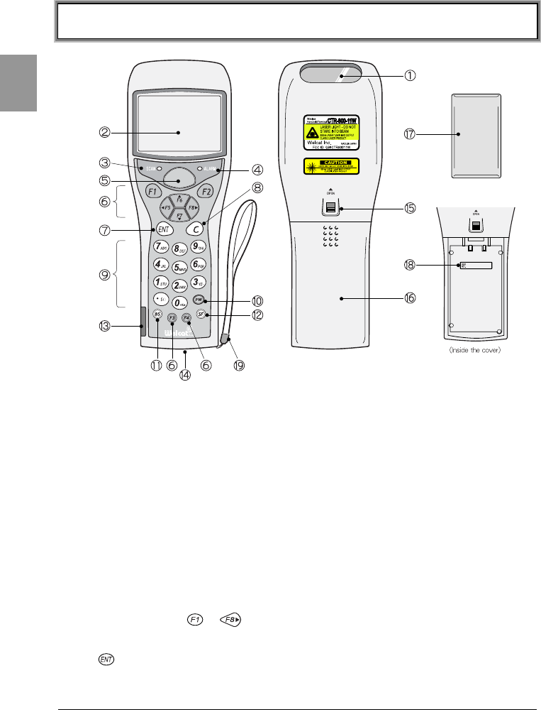
1-1 Part Names
1. Barcode Sensor
The opening from where the barcode is read.
2. LCD (Liquid Crystal Display)
Data and characters are displayed on the LCD.
3. LED Indicator
If a barcode is read correctly, the light will turn green.
4. Warning LED
Shows the signal reception state from an access point during wireless
communications. (P.2-4)
5. Scan Key
Press this key to read a barcode.
6. Function Keys ( -)
Used for changing functions and cursor operation. (P.4-3)
7. Key (Enter Key)
Used when confirming an operation or entering in data.

1-1 Part Names
1-3
Chap.
1
8. Key (Cancellation Key)
Used to delete entered data or to return to the previous screen.
9. Numeric Keys ( ~、)
Used to enter numbers and decimal points.
10. Key (Power Switch)
11. Key (Backspace Key)
Erases the last character entered.
12. Key (Shift Key)
Special functions can be accessed by pressing this key together with other
keys.
13.IrDA Interface
Communicates with a communication cradle (HIF-51) or an exclusive printer
via IrDA.
14.RS-232C Interface
Connects with an exclusive printer or a computer using the optional cable.
15.Battery Pack Lock Lever (P.2-10)
When red is displayed, it is in a locked state.
16.Battery Cover (P.2-10)
Always attach the battery cover while in use.
17.Battery Pack (optional) (P.2-9)
After purchasing and before you use, charge the battery pack.
18.Serial Number
The serial number is indicated inside the main part which contains the battery
pack.
19.Hand Strap
Chapter 1 Quick Guide
1-4
Chap.
1
1-2 Preparation before Use
Please carry out the following preparations before using the CTR-800-11W.
●Battery pack -HBC-51 - (optional)
The battery pack is required in order to use the CTR-800-11W. Please purchase
separately and install it in the CTR-800-11W correctly. (P.2-10)
●Isn't the sensor dirty?
If the sensor is dirty, a barcode cannot be scanned correctly. When dirty, please
wipe lightly with a soft cloth etc.
Please be sure to hold the CTR-800-11W when operating. It may fail if used while
placed on the floor.
Do not place the CTR-800-11W on top of the communication cradle (HIF-51) as
the unit may fall and cause damage to both the communication cradle and the
CTR-800-11W.
1-2 Preparation before Use
1-5
Chap.
1
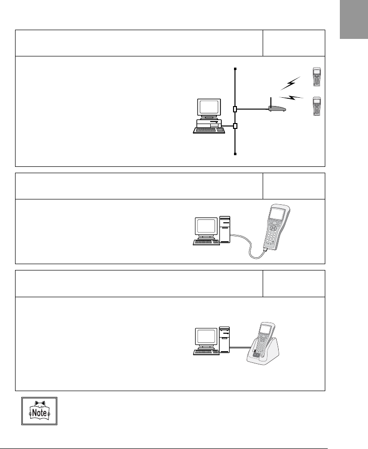
1-2-1 Equipment Connections
Data entered can be transmitted from the CTR-800-11W to a host computer or
the CTR-800-11W can receive data from a host computer.
The following are the methods for connecting to a host computer. Preparations
required depend on the application environment.
Access Point and Wireless Communication P.4-16
The CTR-800-11W communicates via
wireless communication to a host
computer through an access point which
is connected to the Ethernet LAN.
■Purchased Separately
Access Point (our recommended
product), Ethernet cables, HUB
For details about setting up a wireless
network, refer to the Access point Manual
and this document.
Direct connection to a host computer via an RS-232C connector P.4-8
The CTR-800-11W is connected to a host
computer via the PC connection cable
(HOP-C031) and communicates using
RS-232C.
■Purchased Separately
PC Connection Cable (HOP-C031)
The communication cradle (HIF-51) is used to connect the CTR-800-
11W to a host computer, and allows communication via IrDA P. 4-8
A host computer and the communication
cradle (HIF-51) are connected using the
HIF-51 PC connection cable (WRS-
AXC003A). The communication cradle
communicates via IrDA.
■Purchased Separately
Communication cradle (HIF-51)
HIF-51 PC connection cable (WRS-
AXC003A)
If the communication cradle (HIF-51) is connected by a daisy chain connection
(P.6-6), please purchase the daisy chain connection cable (STP-C001A) separately.

Chapter 1 Quick Guide
1-6
Chap.
1
1-2-2 Additional Software
In the case where you want to create a system for data communication between
the CTR-800-11W and a host computer or build a system using the CTR-800
browser, the following software is required.
Program Preparation and use Reference
WebGlider
The WebGlider software is
required when building a Web
based wireless system using
the CTR-800 browser. The
WebGlider package also
includes a DHCP server, an FTP
server, and an operation
monitor etc. to help automate
the CTR-800-11W setup.
Please purchase separately if
needed.
Please install the "WebGlider"
package on a computer and
setup the communication
environment, before
performing data
communication between the
computer and the CTR-800
browser.
For details, please
read the on-line
manual included
with this software.
Handy5250
The Handy 5250 software is
required when creating a
system to connect to an
AS/400 host via the 5250
emulation environment.
Before using, install the Handy
5250 setup utility which will
allow the setup of the
communication environment.
For details, please
read the on-line
manual included
with this software.
Welfer Ⅱ for Windows
Welfer II is required for serial
data transmission and
reception with the host
computer. Please purchase
separately.
Install "Welfer II for Windows"
on the host computer before
performing data
communication.
Please refer to the
included software
manual.
1-3 Wireless Communications
1-7
Chap.
1
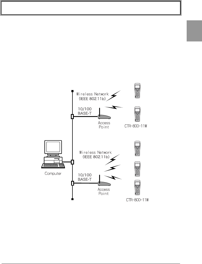
1-3 Wireless Communications
■Wireless function of the CTR-800 series
The CTR-800 series is a handy terminal network system incorporating a wireless
communication system. The barcode terminal is small, lightweight and excels in
portability. It is also suitable for moving around the work place, operating
remotely from the computer while collecting barcode data. The CRT-800-11's
wireless communication system is based on and conforms to the WLAN standard,
IEEE802.11b. The maximum possible wireless transmission speed is
approximately 11Mbps(es). Transmission and reception of scanned barcode data
or files can be performed in real time through the wireless network.
Chapter 1 Quick Guide
1-8
Chap.
1
■The Wireless Communication System
The wireless communication system is based on the IEEE802.11b standard,
which is generally used in Wireless Local Area Networks (WLAN). In almost all
cases, wireless communication can be performed if the access point used is
based on the IEEE802.11b standard.
As for this product, only the infrastructure mode is supported. It does not support
ad hoc mode.
■The role of an access point
An access point provides a wireless service area to a terminal (CTR-800-11W)
and acts as a local bridge, which performs packet transmission between the
cabled LAN and wireless network.
Each terminal has a unique IP address, which allows direct Ethernet LAN
connection through an access point. This allows TCP/IP communication between
the computer and the terminal.
Our recommended access points should be used. For information on manufactures
and part numbers of the recommended access points, refer to our catalog or contact
our sales department.
1-4 Preparation for Data Communication
1-9
Chap.
1
1-4 Preparation for Data Communication
For data communication between a computer and the CTR-800-11W, perform
the following setup.
■Wireless communications
Item Description Reference
page
1SSID Setup Set the SSID (or ESSID) of the
CTR-800-11W to the same as
that of the access point. CTR-
800-11W includes an AP search
function that will acquire and
set up the SSID of an available
access point.
P.4-17
2Security Setup Make the security settings to
the same as the access point.
P.4-18
3TCP/IP Setup Set the TCP/IP address to allow
communication with a
computer via the Ethernet LAN.
P.4-22
4FTP Setup Make the FTP settings to allow
wireless file transfer.
The FTP settings corresponds
to the "WebGlider" FTP server
or general FTP server settings.
P.4-24
5 DHCP Setup Make the DHCP settings when
using the DHCP client function.
This corresponds to the
"WebGlider" DHCP server.
P.4-23
6DNS Setup Make the DNS settings in the
case where the DNS is used for
name resolution.
Whether or not the DNS is used
depends on the application.
P.4-24
Using the computer side DHCP client function (P.4-23), can all be
configured at the same time.
When you use the DHCP client function, "WebGlider" is required.
Since setting the "1. SSID Setup" and "2. Security Setup" using the DHCP client
function creates a security weak point, please do not use this function whenever
possible.

Chapter 1 Quick Guide
1-10
Chap.
1
Once setup is completed, first perform a wireless test (P.4-43) to see if the
terminal can communicate with an access point. Then perform a ping test
(P.4-45) to see if network communication between the terminal and computer
can be performed.
For information about the CTR-800-11W wireless functions, please refer to
"1-3 Wireless Communications" (P.1-7).
■Cable communications
Item Description Reference
page
1Terminal ID
Setup
Set a unique ID number to each
CTR-800-11W.
"Welfer II for Windows" and
"WebGlider" use this ID to identify a
terminal.
P.4-29
2Serial
Communication
Setup
Set the serial communication
conditions and the communication
port (IrDA/RS-232C). Setup "Welfer
II for Windows" and the terminal to
have the same communication
condition setup.
P.4-8
Using the computer side DHCP client function (P.4-23), can be configured
at the same time.
When you use the DHCP client function, "WebGlider" is required.
1-5 Data-Communication Method
1-11
Chap.
1
1-5 Data-Communication Method
Once the equipment has been setup, data communication can be performed
using the following procedures.
■In the case of wireless communications
The procedure for performing wireless communications is as follows.
When you use the DHCP function (P.4-23), "WebGlider" is required.
Once setup is completed, first perform a wireless test to see if the terminal can
communicate with an access point. Then perform a ping test to see if network
communication between the terminal and computer can be performed.
1. Connect the access point to the Ethernet LAN, then setup the access point so
that it can communicate with a host computer.
Please refer to the access point manual included with your access point for
details about the access point setup, Ethernet LAN connections and communi-
cations setup.
2. Turn ON the access point.
3. Turn ON the CTR-800-11W and setup the Wireless communications and
TCP/IP from the System Menu. (P.4-16)
4. Setup FTP to transmit and receive a file.
•See P.4-31 for transmitting a file to a host computer from the CTR-800-11W.
•See P.4-33 for receiving a file from a host computer to the CTR-800-11W.

Chapter 1 Quick Guide
1-12
Chap.
1
■In the case of cable communications
The procedure for performing RS-232C communication or IrDA communication is
as follows.
1. Start the host computer in which "Welfer II for Windows" is installed.
2. After connecting the communication cradle (HIF-51) to the host computer
using a HIF-51 PC connection cable (WRS-AXC003A), turn ON the
communication cradle.
When connecting the CTR-800-11W to a host computer directly, use the PC
connection cable (HOP-C031).
3. Start "Welfer II for Windows" and setup the file transmission and reception.
4. Turn ON the CTR-800-11W and setup the Terminal ID (P.4-29) and serial
communication (P.4-8) from the System Menu.
When using the communication cradle (HIF-51) via a daisy chain connection,
you can transmit one file to two or more terminals at a time from a host com-
puter (broadcast transmission). (P.6-6)
Moreover, in the case where two or more communication cradle s are connect-
ed via a daisy chain connection, it is possible to transmit data to a host com-
puter from any unit.
5. Transmit and receive a file.
• See P.4-31 for transmitting a file to a host computer from the CTR-800-
11W.
• See P.4-33 for receiving a file from a host computer to the CTR-800-11W.

Chapter 2
2 Hardware

Chapter 2 Hardware
2-2
Chap.
2
2-1 Main Features of the CTR-800-11W
1.Ability to implement a cordless communication system
If a terminal is within a service area, the terminal can roam around and
communicate via a wireless transmission system. Moreover, when you need
to extend the system in the future, you can add terminals with ease.
2.Support of TCP/IP protocol
The Wireless Communications comply with the TCP/IP protocol, therefore a
terminal can communicate with the computer via a cabled LAN transparently.
3.High-speed data transmission
The CTR-800-11W is based on the IEEE802.11b standard and can transmit
11Mbps over wireless communication, which is the maximum set in this
standard.
4.IrDA Interface incorporated
The CTR-800-11W is based on the IrDA SIR Ver1.2 standard and achieves a
high-speed file transfer of 115kbps. It can also communicate with an
exclusive printer via IrDA.
5.Vibrator function incorporated as standard
The incorporated vibrator function lets you know that a scan has completed
successfully even while you are in a noisy work area.
6.Use of large capacity battery for extended run time
By using the optional battery pack (HBC-51), it is possible to get 10 hours of
continuous use.
Refer to "2-2-1 Product Specifications" (P.2-3) for the setup of the access
point and CTR-800-11W.
7.Compact and lightweight
The product allows you to carry it easily and use it anywhere within the
operating environment.

2-2 Product Specifications
2-3
Chap.
2
2-2 Product Specifications
2-2-1 Product Specifications
Codes scanned
NW-7, CODE39, JAN-13/8, UPC-A/E, EAN 13/8,
Industrial 2of5, ITF, CODE93, CODE128, and
EAN128
Number digits scanned Max. 72 Digits (data digits)
Scanning width Max. 350mm
Light source Red light semiconductor laser
MRD 25
Scanner
Resolution 0.127mm
FROM 4Mbytes (including 3.2MB for file area)
Memory SRAM 4Mbytes (including 2MB for file area and 1MB for
Application Work area)
Scan success / error Green / Red / Orange
Display LED Warning Red (which illuminates when out of range)
STN Liquid crystal full dot matrix (gray mode)
Kanji
characters
10 characters x 5 lines (12-dot mode)/
8 characters x 4 lines (16-dot mode)
Display Size 128x64
dots ANK 20 characters x 5 lines (12-dot mode)/
16 characters x 4 lines (16-dot mode)
Display area 43(W) x 31(H) mm
Display characters JIS level-1 kanji set, JIS level-2 kanji set, ANK,
symbols, external characters.
Contrast adjustment 8 levels
LCD display
Backlight Yes (LED)
Buzzer Sounds when an error occurs while reading a barcode
Vibrator Vibrates when a barcode has been scanned successfully and when an error
has occurred (operation in synch with the buzzer can be selected).
Dimensions 56.6(W) x160(D) x 37.9(H) mm / grip: 45(W) x26(H) mm
Weight Approximately 193g (including the battery pack)
Main battery Lithium ion battery
Power source Backup battery Lithium secondary battery (maintenance-free)
Working temperature -5 to 45℃
Working humidity 20-80%RH (devoid of condensation)
Storage temperature -10 to 60℃
Storage humidity 10-90%RH (devoid of condensation)
Drip-proof JIS II type
Drop impact proof 120cm (onto concrete)
Artificial
light
4,800 lx typ.
(excluding sodium lamps)
Operating
environment
Illumination conditions
Sunlight 107,000 lx typ.
Approximately 10 hours
Continuous
operation time Setup conditions ●Access point setup
Beacon cycle: 100msec, DTIM: 2
●CTR-800-11W Conditions
Power-saving timeout: immediate; scan cycle: one
scan per20 sec.; wireless transmission and reception
of 100-bytedata after successful scan
Clock function Year (4 digits)/Month/Date/Hour/Minute, with automatic leap year
compensation
External interface IrDA(compliant with the IrDA SIR 1.2 Low Power Option Standard)/ RS
-232C
Chapter 2 Hardware
2-4
Chap.
2
International standards IEEE802.11b
Domestic standards ARIB STD-T66、STD-33A
Communication system Spread Spectrum system (Direct Spread
system)
Wireless frequency 2.4GHz band
Antenna power output Less than 10mW/MHz
Transmission speed 11/5.5/2/1 Mbps (switched automatically /
fixed)
Number of channels 14
Security SSID、WEP (40/128bit)
Antenna built in the body
Wireless
Transmission range indoors: approximately 75m:
outdoors: approximately 200m
Management
function
SNMP agent (SNMPv1)
MIB Support MIB-II (RFC1213) *Partially not supported
Welcat Enterprise MIB
■Display of alarm LED during wireless communications
The state and meaning of the alarm LED during wireless communications are as
follows.
LED state Meaning
OFF Communication with an access point is possible. Or no
communication is currently taking place.
Blinking / ON
Communication with an access point has been attempted but
synchronization with the access point cannot be achieved. When
the barcode scanner goes out of sync with the access point, the
LED will blink for approximately 3 seconds and will turn on. (The
LED will turn OFF when the barcode scanner syncs with the
access point again.)
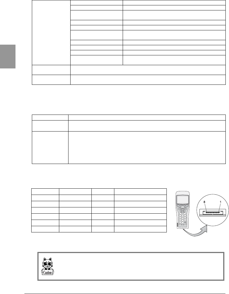
2-2-2 RS-232C Interface
■Signal names and connector pin layout
Pin number Terminal name Direction Description
2 GND - Signal ground
3 TxD Output Transmit data
4 RTS Output Send request
5 RxD Input Receive data
6CTSInputTransmission possible
1, 7, 8 - - Reserved
Connector type: 3260-8S2 made by Hirose,
Terminal signal level: JISX5101 equivalent
The reserved pins mentioned above have already been reserved by the system. Please do
not use applications, cables etc. other than those recommended for use with the CTR-
800-11W.
In order to carry out direct file transfer between the CTR-800-11W and the host com-
puter, please purchase the PC connection cable (HOP-C031) separately.
2-2 Product Specifications
2-5
Chap.
2
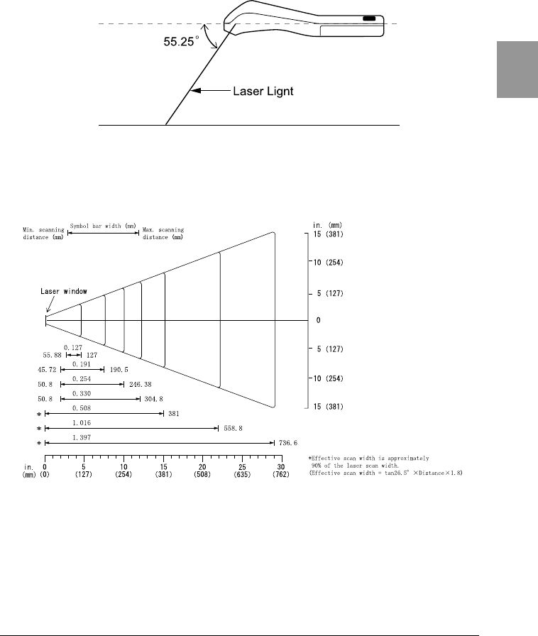
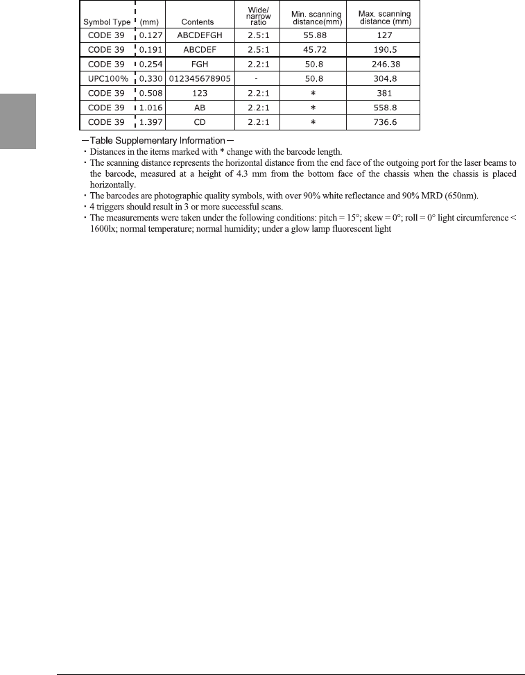
2-2-3 Scanning Specifications
■Laser light irradiation angle
The angle of the laser light irradiated from the CTR-800-11W is 55.25 degrees.
■Scanning Depth
The range across which a barcode can be scanned is called a "scanning depth."
The scanning depth for the CTR-800-11W is as shown in the figure below.
●Scanning range and resolution depth
Chapter 2 Hardware
2-6
Chap.
2
●Scanning distance range
2-2 Product Specifications
2-7
Chap.
2
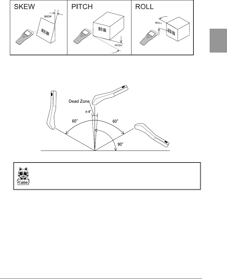
■Inclination of a barcode and the angle with which it can be read
The following are the three kinds of a barcode inclination.
●Skew
With a distance of 254mm, and a resolution of 0.508mm, scanning is possible up
to 60° perpendicular to the upper and lower sides of a barcode.
The range of ±4° around a vertical line from the front face of a bar code is the
"Dead Zone" caused by the specular reflection; scanning may become poor within
this range.
Change the angle if you cannot read the barcode and scan it again.
Chapter 2 Hardware
2-8
Chap.
2
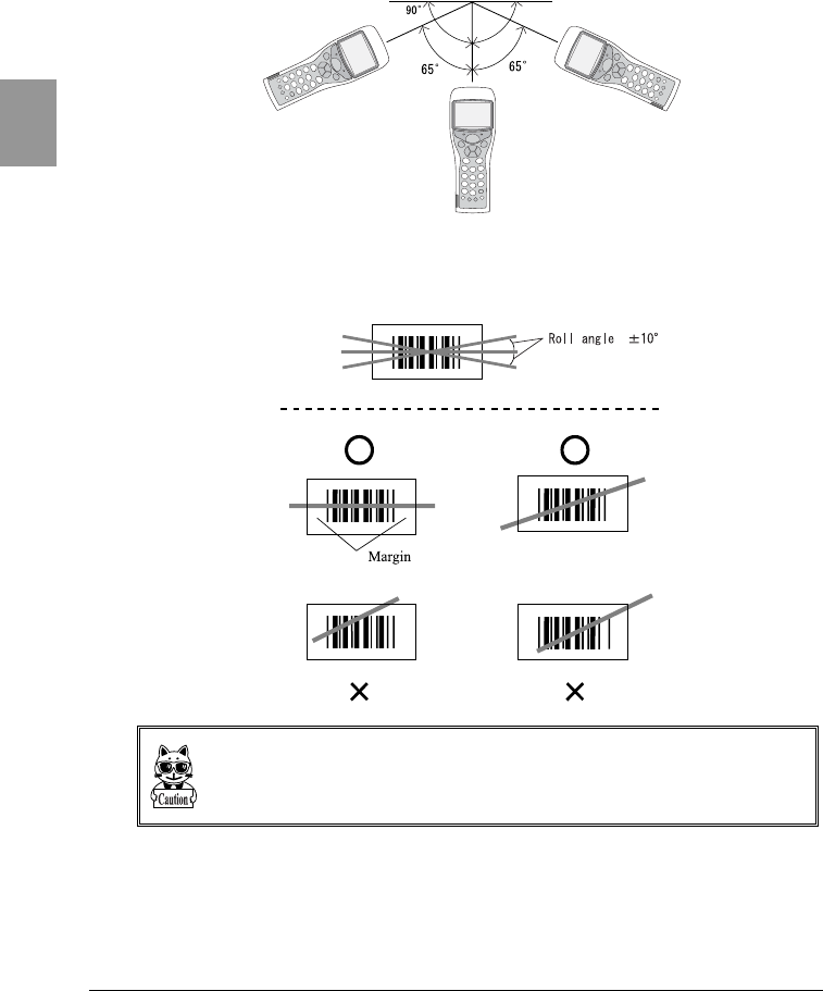
●Pitch
With a distance of 177.8mm and a resolution of 0.508mm, scanning is possible
up to 65° perpendicular to the right and left of a barcode.
●Roll
With a distance of 254mm and a resolution of 0.508mm, the roll is the angle with
which the laser light irradiates the barcode.
The laser light should always cross the whole label. Make sure it also irradiates the
unfilled space (margin) to the right and left of the barcode.
2-3 Battery Pack (HBC-51)
2-9
Chap.
2
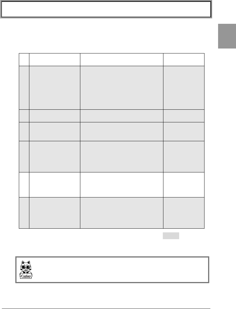
2-3 Battery Pack (HBC-51)
The battery pack is not included with the CTR-800-11W. Please purchase sepa-
rately and use it correctly.
Be sure to follow the precautions below when handling the battery pack.
•After purchasing, be sure to fully charge the battery pack before using.
•Be sure to shut off the power before removing the battery pack. If the
battery pack is removed during operation, the program and data may be
corrupted.
•Be sure not to touch the electrodes with your hand, and avoid dust on the
electrodes. Otherwise this may cause poor contact with the battery pack
and the CTR-800-11W. When dirty, wipe clean with a dry soft cloth etc.
•When installing and removing the battery pack, use a desk or other
appropriate surface as the working table so that it cannot fall onto you
feet.
•Be sure to attach the battery cover before use.
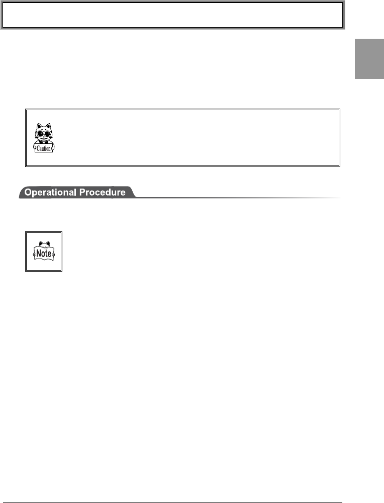
2-3-1 Charging the Battery Pack
Use our dedicated charger (HQC-51/HQC-54) to charge the battery pack.
Charging will be completed in approximately 2.5 hours.
Please purchase the dedicated charger (HQC-51/HQC-54) separately.
For details, please read the instruction manual included with the dedicated charger.
Chapter 2 Hardware
2-10
Chap.
2
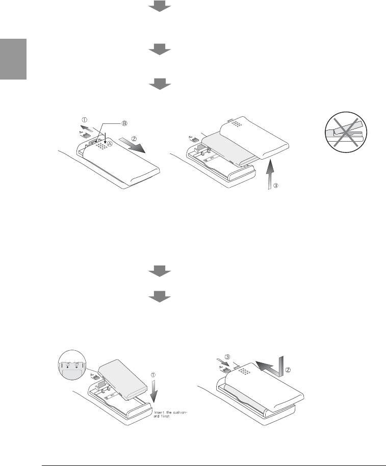
2-3-2 Removing the Battery Pack
Release the lock by pulling up the lock lever in the direction (1). When the lock is
released, the red indication of a lock lever will disappear.
Slide the battery cover in the direction (2). If the battery cover is hard to remove,
hold down at point A shown in the illustration then slide in the direction of the
arrow.
Slide the battery cover in the direction (2) until the tab (point B in the illustration)
of the battery cover is completely exposed.
Remove the battery cover straight up as shown in the direction (3), and take out
the inner battery pack.
2-3-3 Installing the Battery Pack
Remove the battery cover, then position the electrodes of the battery pack above
the electrodes of the main body, and then insert the battery pack as shown in
(1).
Attach the battery cover by sliding in the direction (2).
Check and make sure that the tab of the battery cover has been completely
inserted in the main body, and then return the lock lever in the direction (3).
Please check that it is completely locked and that the battery cover can not come
off. If locked, the lock lever indication will appear as red.
If the battery cover is
removed on an angle o
r
otherwise handled
incorrectly, the battery
cover and/or the main
body may be damaged.

2-3 Battery Pack (HBC-51)
2-11
Chap.
2
2-3-4 Replacing the Worn out Battery Pack
A battery pack is an expendable item. Even if the battery pack is used correctly,
it will deteriorate gradually in the course of being charged and discharged
repeatedly.
If the usage time is becoming shorter even after charging for the specified
charging time, please replace the existing battery pack with a new one.
■About prolonged storage
Since the battery may deteriorate rapidly by over discharging if left for an
extended period of time, be sure to periodically charge the battery. When you do
not use it for an extended period of time, take note of the following.
•When you do not use it for one month or more, remove the battery pack
and keep it at room temperature.
2-3-5 Cautions about Cleaning of Electrodes
When the operational time has become shorter or it is having trouble starting,
poor contact between electrodes because of dirt, may be the cause instead of a
degrading battery. If this is the case, cleaning both the battery electrodes and
the main body electrodes will improve this condition.
■Methods for cleaning the electrodes
Please wipe the dirty electrodes with a clean dry soft cloth, a swab, etc. Never rub
the electrodes with an unclean cloth, fingers or a hard object. Wipe the
electrodes lightly, especially the main body electrodes, else they may get
scratched or deformed.
Chapter 2 Hardware
2-12
Chap.
2
2-4 Memory Backup Period
(Battery for backup)
The memory backup period is approximately three months.
In addition to the battery pack, a backup battery is built into the CTR-800-11W
for maintaining data saved on the S drive and the built-in clock of the CTR-
800-11W.
The memory backup period is the period from when the backup battery was fully
charged until it is completely discharged.
Battery pack Backup Battery
Battery Optional Built-in
Use Required for operation of
the CTR-800-11W
Maintains the data saved on
the S Drive and the built-in
clock of the CTR-800-11W.
Char
g
in
g
time
2.5 hours
*Use the dedicated charger
(
HQC-51/HQC-54
)
(
P.2-9
)
To be fully charged, the backup
battery takes approximately
two days from when it starts
the charging process as soon
as a fully charged battery pack
is installed in the CTR-800-
11W. (P.2-13)
Estimated
usable period
(When fully
Charged)
Approximately 10 hours.
Refer to "2-2-1 Product
Specifications" (P.2-3)
Approximately three months
after the battery pack has fully
discharged.
Precautions in
Use
If the battery pack has not
been recharged within
three months or more, it
may degenerate and
become impossible to use.
Ensure to charge it at least
once within three months.
(P.2-11)
If the CTR-800-11W is left with
a fully discharged battery pack
or left with the battery pack
removed for three months or
more, the backup battery will
also fully discharge and then
the built-in clock settings and
the data saved on the S Drive
will be lost. Ensure to charge
the backup battery using a fully
charged battery pack at least
once within three months.
(P.2-13)
Any data lost at the time when the backup battery is fully discharged cannot be
restored. For data preservation, equip the CTR-800-11W with a fully charged bat-
tery pack, and press the key to turn ON the CTR-800-11W.
This should be done at least once every three months. (Refer to "2-4-1 Charging
the Backup Battery" (P.2-13)
The Memory backup time varies depending on the surrounding environment. For
example, backup time will be drastically reduced in temperature below 0ºC and
above 40ºC and more. It is recommended to use the battery at room temperature.
2-4 Memory Backup Period
(Battery for backup)
2-13
Chap.
2
2-4-1 Charging the Backup Battery
This section describes the method for charging the backup battery.
1. Put the CTR-800-11W (with no battery pack installed) and one fully charged
battery pack at a handy place.
2. Install the CTR-800-11W with the battery pack. (P.2-10)
The charging process does not start by only installing the battery pack.
3. Press the key and turn ON the power. The charging process for the backup
battery will then be started.
If the Backup Battery has completely been discharged, do not remove the
battery pack for at least two days after the start of the charging process.
4. Once the charging process starts, even if the key is pressed and the
power is turned OFF or the CTR-800-11W is used for normal operation (such
as scanning barcodes), the charging process for the backup battery will
continue until the battery pack is removed or totally discharged.
5. If the battery pack is fully discharged or removed during the charging process,
the backup battery charging process will stop. To start the process again,
repeat from step 1.

Chapter 2 Hardware
2-14
Chap.
2
2-4-2 S Drive Data
The CTR-800-11W has two drives, the S Drive and the F Drive, where files can be
saved.
The data entered by a user is saved in the S Drive. If the CTR-800-11W is left for
an extended period of time without charging, the contents of the S Drive may be
lost because the S Drive is volatile. The S Drives memory backup period is
approximately three months at standard room temperature when fully charged.
Save the application program on the F Drive. The F Drive is a nonvolatile drive,
therefore the contents will be preserved, even if the battery is fully discharged.
Refer to "3-1-1 Data Storage" (P.3-3) for details about storing data.
2-5 Suspend Function
2-15
Chap.
2
2-5 Suspend Function
The CTR-800-11W supports a suspend function. (P.4-15)
The suspend function can be enabled through the System Menu and if selected,
the next time the key is pressed on the CTR-800-11W, the suspend function
will be used.
Suspend mode ON After the CTR-800-11W is powered OFF, the
next time the key is pressed, it will suspend
operation where it was just before the power
was turned OFF.
Suspend mode OFF After the CTR-800-11W is powered OFF, the
next time the key is pressed, it will begin
operation from the start.
In the case where the battery is disconnected while the power is ON, the operation
will begin from the start regardless of the suspend mode settings. If the DHCP has
been set to "execute at startup," the program process will start from the beginning,
regardless of the suspend mode settings.
In the case where the backup battery is fully discharged, the program will execute
from the start, regardless of the suspend mode settings. Refer to "2-4-1 Charging
the Backup Battery"(P.2-13) for information about charging the backup battery.
Chapter 2 Hardware
2-16
Chap.
2
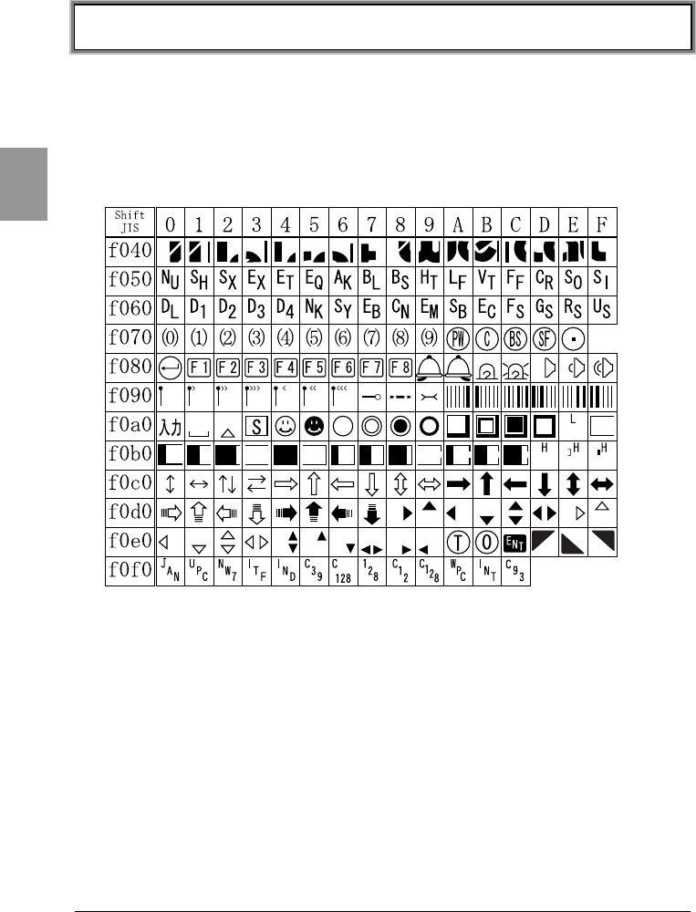
2-6 Screen Output Characters
■Double-byte characters
Shift JIS (OADG 2byte character set) is used for double-byte characters.
The first bytes of Shift JIS are located at 81-9F and E0-FC, and the second at
40-7E and 80-FC. The following table is an extended character list created by our
company.

2-6 Screen Output Characters
2-17
Chap.
2
■Single-byte characters
The OADG single-byte character set is used for single-byte characters.
The five characters, 80, A0, FD, FE and FF, are extended characters created by
our company.

Chapter 3
3 Software
Chapter 3 Software
3-2
Chap.
3
3-1 CTR-800-11W Software
The CTR-800-11W software consists of the following two types.
System program
Controls the basic operation of the CTR-800-
11W. It is equivalent to an OS (operating
system) of a personal computer, and is
preinstalled in the CTR-800-11W. The System
Menu, which sets the basic parameters for
operation and performs various verifications, is
a part of the system program.
Application program
Used for user operations processing. This
program is mainly used for scanning barcodes,
data transmission to a computer, etc.
In the case that "WebGlider" is used to configure
the system, the "CTR-800 browser
(WEB811.OUT)" has been loaded on the CTR-
800-11W.
If you purchase "WebGlider," you can easily
combine it with the CTR-800 browser to build a
Web based system.
The optional application development kit allows
you to create original programs to meet a wide
range of business needs.
Refer to "4-2 System Menu" (P.4-3) for detailed information about the System
Menu.
For information about "WebGlider," see the online manual included with the
product package.

3-1 CTR-800-11W Software
3-3
Chap.
3
3-1-1 Data Storage
■Information about the data storage (drive configuration)
The CTR-800-11W has two drives for storing data. The S Drive and the F Drive.
Drive Data Retention Use Maximum
Capacity
S Drive
●Volatile memory
Once the backup
battery is discharged
the contents of the
drive will be lost.
Used to store files that
are frequently written
to.
32 files
F Drive
●Non-volatile memory
The contents of this
drive will be retained
after the backup
battery is discharged.
Used to store files that
are not written to, such
as application and the
database master files.
50 files
When the F Drive receives a file, the S Drive receives the file first then moves it
to the F Drive. In case where the F Drive receives a file, confirm that there is
enough storage space on the S Drive beforehand.
Also, if a file with the same name exists in the S Drive, the file that was stored in
the S Drive will be erased after moving the file to the F Drive.
■File Naming
The file names used by the CTR-800-11W are subject to the following
restrictions.
File name
A file name can be 1 to 8 byte long, in any combination
consisting of alphabet (A-Z), numbers (0-9), and/or symbols
(!#%&'()@^_{} -). Double-byte characters cannot be used.
Extension
Specify an extension using 1 to 3 bytes of characters. The
extension can be omitted. The characters that can be used are
the same as the characters for the file name.
When specifying an extension a ."" is needed between the file
name and the extension.
The file with an extension of ."OUT" is recognized as an
application file.
The file with an extension of ."FNV" is recognized as a font file.
Chapter 3 Software
3-4
Chap.
3
■The files generated by the CTR-800 Browser
In the case where the CTR-800 browser is being used for HTTP communication,
the following files are created in the S Drive. Since a file with the same name is
overwritten, be sure to use a different name than the following file names.
• HTTP.LOG
• HTTPTEMP (with no extension)
• HEADTEMP (with no extension)
Since these files are going to be created, the actual number of files you can store
on the S Drive is 29.
When the above-mentioned files cannot be created because there are too many
files or there is no available space on the S Drive, the CTR-800 browser will be
unable to operate normally.
3-1-2 System Menu
Through the System Menu, you can make the CTR-800-11W fundamental
operation settings, install the application program and transmit data files, etc.
Refer to "4-2 System Menu" (P. 4-3) for details about the System Menu.
3-1-3 CTR-800 Browser
The CTR-800-11W dedicated browser (WEB811.OUT) is preinstalled in the
CTR-800-11W before shipment. This application is used in combination with
"WebGlider" to build a Web based system.
For information about how to implement the application process, refer to the
included on-line manual for "WebGlider."
When developing unique applications using either the application development
kit HAP-SDK -11 or the model-specific CTR-800-11W library HAP-LIB-82, or
when using the emulator software "Handy5250," the CTR-800 browser is not
required and can be deleted.

Chapter 4
4 Setup

Chapter 4 Settings
4-2
Chap.
4
4-1 Introduction
The CTR-800-11W's System Menu can be used for various tasks such as network
communication setup, operation setup, the installation of application programs,
data file transmission and verification checks, etc.
■System Menu
The System Menu is a part of the system program (P.3-2), which is preinstalled
in the CTR-800-11W as one of the functions that comprise the operating system.
It also provides a platform for installing application programs and performing
environmental setup for the whole system.
This chapter describes how to set up the CTR-800-11W and perform various
verification checks, with primary focus on how to use the "System Menu."
4-2 System Menu
4-3
Chap.
4
4-2 System Menu
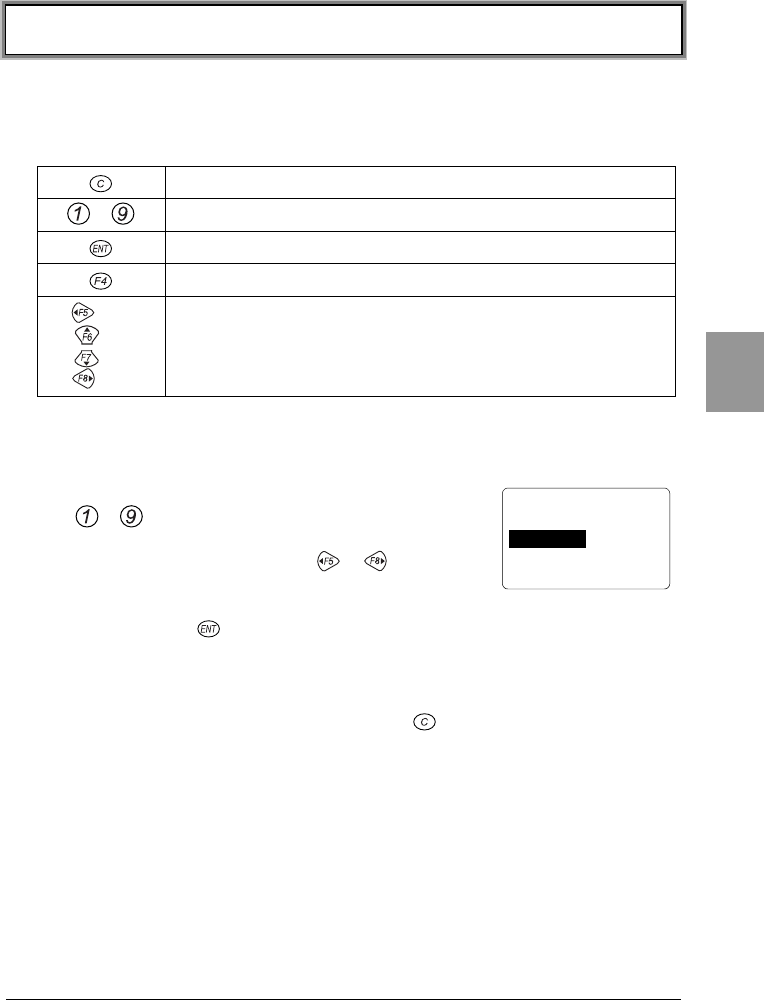
4-2-1 System Menu Operations
The following keys are used for operating the System Menu.
Used to return to the previous menu.
~Used to select the corresponding menu item.
Used to confirm the selected menu item.
Turns on the back light.
(←)
(↑)
(↓)
(→)
Used to move the cursor (selected area) in the direction of the
arrow.
■Operation method
●Selecting a Menu Item
Either press a number key on the numeric keypad
(~) which corresponds to the number shown
on the left of the menu item, or move the cursor in
any direction using the keys ~. When the
cursor moves onto a menu item, it becomes
highlighted (colors reversed = selected). To select the current highlighted
item, press the key. This will execute the selected menu item's function
or display the next sub-menu.
●Returning to the previous menu
To return to the previous menu, press the key. Once you have returned
to the previous menu, the menu item that was previously selected is
highlighted (colors reversed).
< System Menu >
1:System 4:File
2:Network 5:Status
3:TermID 6:Test

Chapter 4 Settings
4-4
Chap.
4
■About the screen display
Depending on the menu (screen) displayed, the characters "F:~" or "S:~" may
be displayed on the left-hand side of an item. If these characters are displayed on
the left-hand side of an item, they represent the following: "F" = "F Drive" and
"S" = "S Drive."
When all of the menu items cannot be displayed in one
screen, [↑] (when menu items are hidden above the
screen) or [↓] (when menu items are hidden below the
screen) is displayed on the left-hand side of a screen. If
the cursor is moved to a hidden menu item, the screen
will scroll automatically.
■Setting the IP address, etc.
The IP address etc, is set in form of "000.000.000.000." When you change a
value, move the cursor to the part you want to change, and overwrite with the
new value.
The key and the key cannot be used to modify the values.
If entering values less than 3 digits in length, the remaining digits have to be 0,
for example "001."
< Startup Program >
F:SAMPLE1.OUT 35K
F:SAMPLE2.OUT 35K
F:SAMPLE3.OUT 35K
↓
F:SAMPLE4.OUT 35K
4-3 Starting the System Menu
4-5
Chap.
4
4-3 Starting the System Menu
4-3-1 How to Start the System Menu
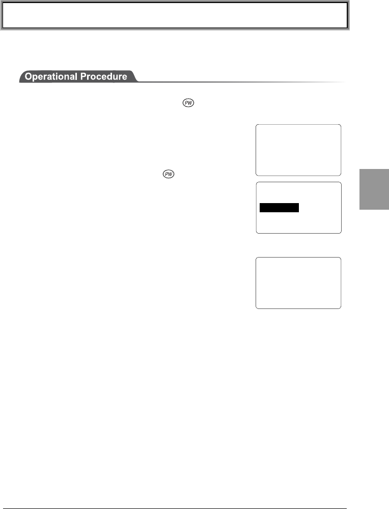
1. Once the CTR-800-11W has been correctly installed with a battery pack and
if the current state is OFF, press the key for approximately 1 second. The
power will turn ON and the System Menu will be started.
2. The System Menu is displayed immediately after the
opening screen.
If an application is set for "Startup" (P.4-7), hold down
the scan key and then press the key to start the
System Menu.
4-3-2 Executing a DHCP Request
If the network DHCP setup (P.4-23) is set as "Run at
startup", a DHCP request is executed immediately after
the CTR-800-11W starts.
If the system is in the state where wireless
communications with an access point is possible and if
the DHCP server and FTP server of the "WebGlider" network management tool
have been started, the various environmental setting values and specified files
will be downloaded to the CTR-800-11W and automatic setup will be performed
via the TCP/IP network.
After the DHCP request has been executed, the applications set for "Automatic
Launch," if any, will start. (P.4-7)
4-3-3 Starting State for Wireless Operation
Immediately after starting, the CTR-800-11W's wireless communication unit is
set to a suspended state. If the wireless communications related menu is
selected immediately after starting, the CTR-800-11W will be ready for
communication within 0.5 to 1 second.
CTR-800-11W
(C)2003 Welcat Inc.
< System Menu >
1:System 4:File
2:Network 5:Status
3:TermID 6:Test
< DHCP Client >
Connect to
DHCP server ..
Chapter 4 Settings
4-6
Chap.
4
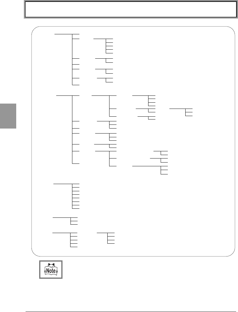
4-4 System Menu List
3:TermID
2:Site Survey
6:Test 1:RF 1:Parameter
3:Ping
4:Searach AP
2:COM
3:Barcode
4:LCD
5:Key
5:Status 1:Battery
2:Version
3:Clock
7:Drive
1:Execute
2:Send
3:Receive
4:Delete
5:Test
6:Property
4:File
8:Font
2:Network 1:RF 1:Basic 1:SSID
2:Roaming
3:DOZE Timeout
4:Tx Speed
2:Security 1:WEP
2:AuthenMode
1:WEP
2:TxKEY_ID
3:KEY Data
3:Advanced 1:Preamble
2:RTS_Threshold
2:TCP/IP 1:IP address
2:Subnet Mask
3:Gateway
3:DHCP
7:MAC
4:FTP 1:Host address
2:Username
3:Password
5:DNS 1:Primary Server
2:Secondary Server
6:SNMP 1:Community(R/Only)
2:Community(R/W)
3:Trap
1:Community Name
2:Manager Address
1:Community Name
2:Manager Address
1:Community Name
2:Manager Address
3:Authentication
7:Suspend
1:Buzzer Volume
1:System 1:Startup
2:COM 1:Speed
2:Data Bits
3:Stop Bits
4:Parity
5:Port
3:Clock
2:Manual Setup
4:LCD
5:Buzzer
2:Device Type
6:Scanner 1:Trigger Mode
2:Power Mode
1:Use DHCP
Please refer to the "System Menu Factory Settings" (Appendix A-2) for in-
formation about the System Menu factory settings.
4-5 System Setup Menu
4-7
Chap.
4
4-5 System Setup Menu
4-5-1 Setting the Programs for Automatic Launch
You can set programs to launch automatically when the power is turned ON. In
the factory settings, the System Menu is set to launch automatically.
When the DHCP function (P.4-23) is enabled, these settings can be made
automatically.
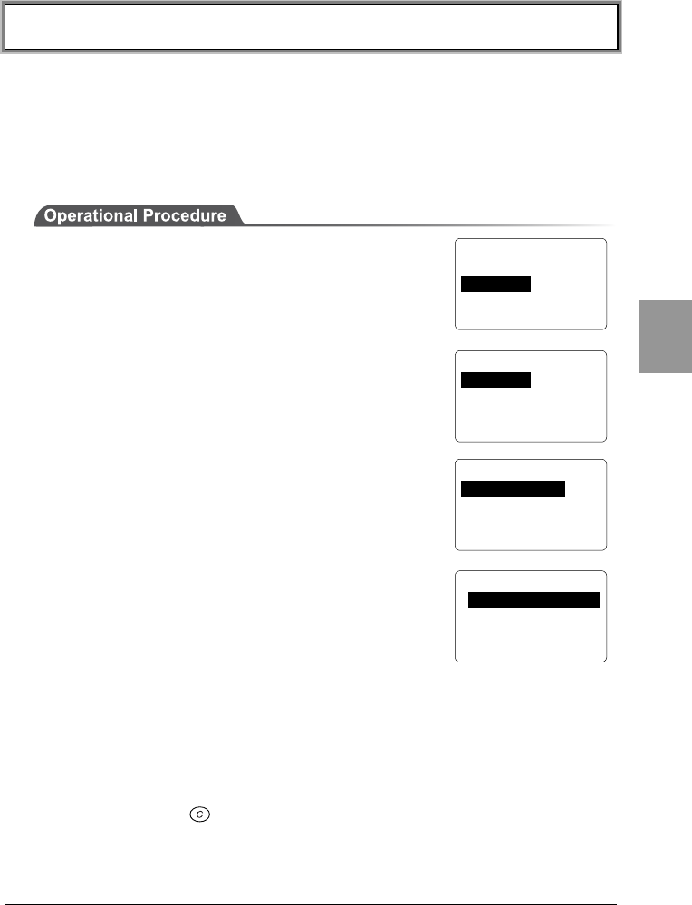
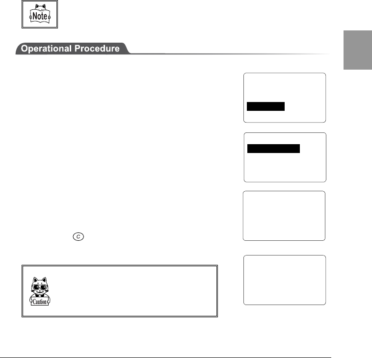
1. From the System Menu, select "1:System."
2. Then select "1:Startup."
3. Select "1:System Menu" or "2: User Program." The
current program names are displayed on the bottom
line.
4. If "1:System Menu" is selected, the System Menu
will be set to launch automatically immediately after
the power is turned ON.
If "2:User Program" is selected, a list of currently
installed applications is displayed. From this list,
select an application.
5. Once an application is selected, the name of the application will be displayed
on the bottom line of the screen.
■When no application is stored
When there are no applications stored, the message "File not found" will be
displayed. Press the key to go back to the previous screen.
< System Menu >
1:System 4:File
2:Network 5:Status
3:TermID 6:Test
< System Config >
1:Startup 5:Buzzer
2:COM 6:Scanner
3:Clock 7:Suspend
4:LCD
< Startup Program >
1:System Menu
2:User Program
[System Menu]
< Startup Program >
F:WEB811S.OUT 200K
Chapter 4 Settings
4-8
Chap.
4
4-5-2 Serial Communication Setup
This section describes how to set up the serial port (RS-232C or IrDA)
communication conditions. When the DHCP function (P.4-23) is enabled, these
conditions can be set up automatically.
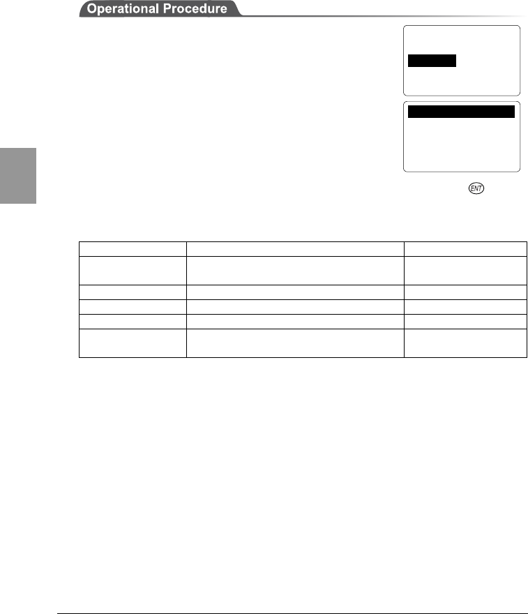
1. From the System Menu, select "1:System."
2. Then select "2:COM" to display the current
communication setup.
Move the cursor to select each individual item. If desired, press the key to
change the current value. The following table shows each item and its range of
settings.
Item Possible Setting Range Factory settings
1:Baud rate 2400bps・9600bps・19200bps・
38400bps・57600bps・115200bps 115200bps
2:Data length 7 bits or 8 bits 8 bits
3:Stop bit length 1 bit or 2 bits 1 bits
4:Parity Odd Parity, Even Parity or No Parity No Parity
5:Port IrDA (infrared data communication)
or RS-232C IrDA
< System Config >
1:Startup 5:Buzzer
2:COM 6:Scanner
3:Clock 7:Suspend
4:LCD
1:Speed 115200bps
2:Data Bits 8bit
3:Stop Bits 1bit
4:Parity None
5:Port IrDA
4-5 System Setup Menu
4-9
Chap.
4
4-5-3 Clock Setup
Reference the time on the host computer to set up the system time.
You can also set up the time manually. In the case where the DHCP function
(P.4-23) is enabled, this setup can be made automatically.
In order to receive the time from the host computer, please check the following
in advance.
•Has the communication setup (SSID, WEP, etc.) been made correctly?
•Have the access point and the host computer been setup and connect correctly?
•Are the access point and the host computer turned on?
•Is the access point operating normally?
For detailed information on wireless network configuration, refer to the access
point (our recommended item) manual included with the access point.
1. From the System Menu, select "1:System."
2. Then select "3:Clock."
3. Then select either "1:Use DHCP" or "2: Manual
setup."
4. If "1:Use DHCP" is selected, the time data is received
from the DHCP server of the "WebGlider" network
management tool. Once completed, the time will be
displayed.
Press the key to return back to the previous
screen.
When setting up the clock via the "Server
Setup", the DHCP server of the "WebGlider"
network management tool must be running.
< System Config >
1:Startup 5:Buzzer
2:COM 6:Scanner
3:Clock 7:Suspend
4:LCD
< Clock Setup >
Time and date are
asked to server..
< Date
/
Time >
2003 / 07 / 01
02 : 35 : 47
< Clock Setup >
1:Use DHCP
2:Manual Setup
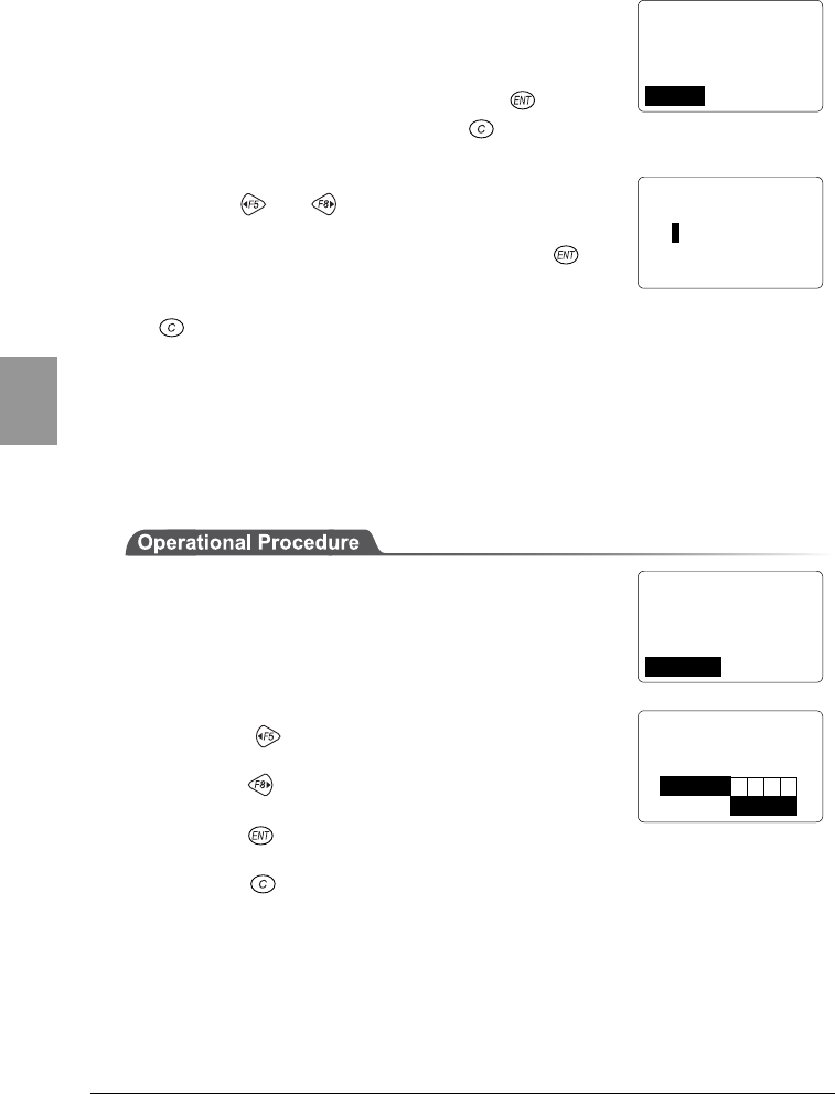
Chapter 4 Settings
4-10
Chap.
4
5. In the case where wireless communications has
failed, the confirmation screen for manual setup will
appear after several seconds.
If you want to try to receive the time from the server
again, select "1: Retry" then press the key.
To stop the clock setup, press the key.
6. When manually entering the time, select "2:Manual"
from either screen (3) or (5) to enter the time.
Use the or keys to toggle through year,
month, date, hour, minute and seconds, and enter
the values using the numeric keys. Press the key
to confirm the values you have entered.
To cancel manual entry and return the clock to its original value, press the
key.
Refer to "4-9-3 Clock" (P.4-42) to check the time setting.
4-5-4 Adjusting the Screen Contrast
You can set the contrast of the liquid crystal display in 8 levels.
1. From the System Menu, select "1:System."
2. Then select "4:LCD."
3. Set the screen contrast as follows:
Press the key to make the display one level
lighter.
Press the key is pressed, the display will become
one level darker.
Press the key to confirm the setup and return to
the previous screen.
Press the key to stop adjusting and return the level back to its original
value.
< Clock Setup >
Failed to sync clock.
Setup by manual?
1:Retry 2:Manual
< Date
/
Time >
2003 / 07 / 01
02 : 35 : 47
< System Config >
1:Startup 5:Buzzer
2:COM 6:Scanner
3:Clock 7:Suspend
4:LCD
< LCD Contrast >
F5← →F8
L
H
Sample Sample
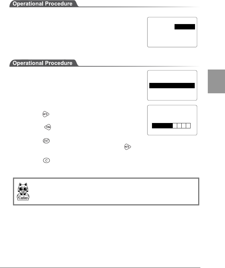
4-5 System Setup Menu
4-11
Chap.
4
4-5-5 Buzzer and Vibrator Setup
You can set either the buzzer or the vibrator or both to notify a successful key
entry or scan.
1. From the System Menu, select "1:System."
2. Then select "5:Buzzer."
■Adjusting the buzzer volume
Set the volume of the buzzer in 8 levels.
1. Select "1:Buzzer Volume" to set the volume of the
buzzer.
2. Set the volume of the buzzer as follows:
Press the key to reduce the volume by one level
(the minimum level is 1).
Press the key to increase the volume by one
level (the maximum level is 8).
Press the key to confirm the setup.
If the value is set to ("1") by pressing the key, the CTR-800-11W will
become silent (the vibrator won't vibrate).
Press the key to stop adjusting and return the level back to its original
value.
The vibrator vibrates at a constant frequency regardless of the volume setting for
the buzzer (Levels 2 to 8).
< System Config >
1:Startup 5:Buzzer
2:COM 6:Scanner
3:Clock 7:Suspend
4:LCD
< Buzzer
/
Vibrator >
1:Buzzer Volume 3
2:Device Type BUZ
< Buzzer Volume >
F5← →F8
L
H

Chapter 4 Settings
4-12
Chap.
4
■Selecting a device
1. Select "2: Device Type" to toggle between the
buzzer and the vibrator.
2. "1:Buzzer" = a beep sounds.
"2:Vibrator" = the main body vibrates.
"3:Both" = a beep sounds and the main body
vibrates.
< Buzzer
/
Vibrator >
1:Buzzer Volume 3
2:Device Type BUZ
< Device Type >
1:Buzzer
2:Vibrator
3:Both
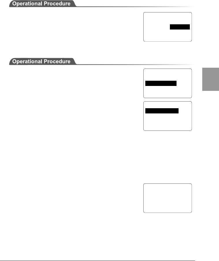
4-5 System Setup Menu
4-13
Chap.
4
4-5-6 Scanner Setup
Set up the operating conditions for the laser scanner while the application
program is running.
1. From the System Menu, select "1:System."
2. Then select "6:Scanner."
■Setting the trigger mode
Set the mode in which the scanning key operates.
1. Select "1:Trigger Mode."
●Normal Mode
When the scan key is pressed, the laser turns on and
scanning can be performed anytime.
●Duplex Mode
When the scan key is pressed, the laser will flash. If the scan key is pressed again,
the laser will turn on and scanning will start.
●Release Mode
When the scan key is pressed, the laser will flash. If the scan key is then released,
the light will turn on and scanning will start.
■Setting the laser irradiation time
After setting the trigger mode, set the laser irradiation
time.
Set the value in the range between 0 and 65536 seconds.
The laser is turned off when a barcode is not scanned
successfully within the specified time.
The laser remains on when this value is set to 0 seconds.
< System Config >
1:Startup 5:Buzzer
2:COM 6:Scanner
3:Clock 7:Suspend
4:LCD
< Scanner Setup >
1:Trigger Mode
2:Power Mode
< Trigger Mode >
1:Normal Mode
2:Duplex Mode
3:Release Mode
< Laser On Time >
[ 00020 sec.]

Chapter 4 Settings
4-14
Chap.
4
■Setting the power save mode
You can save the battery power by setting the CTR-800-11W to the battery save
mode, as described below.
1. Select "2: Power Mode."
●Continuous On
The power save mode is not used.
●Middle Power
If a barcode is successfully scanned, the laser will turn
off automatically. Since the power supply to the scanner part is still on, the next
time you scan a barcode, the startup time will be shorter than during the full save
mode.
●Low Power
If a barcode is successfully scanned, the power to the scanning part will be
turned off. The next time you scan a barcode, the startup time will be longer than
during the quick save mode.
< Scanner Setup >
1:Trigger Mode
2:Power Mode
< Power Mode >
1:Continuous On
2:Middle Power
3:Low Power
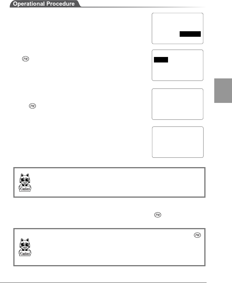
4-5 System Setup Menu
4-15
Chap.
4
4-5-7 Suspend Mode Setup
This section describes how to set up the suspend function.
1. From the System Menu, select "1:System."
2. Then select "7:Suspend."
●Suspend ON
After the CTR-800-11W's power is off, and the next time
the key is pressed to start it, it will resume
processing from where it was when the power was last
turned off.
The screen shown right will be displayed when the
CTR-800-11W is started with the suspend mode enabled.
(If the key is pressed while the scan key is being
pressed, the suspend mode will be canceled and the
restart process will be executed from the beginning).
Just before the power is turned OFF with the suspend
mode enabled, the screen shown right is displayed.
(Before removing the battery pack, wait for about 3
seconds after the screen (shown right) has
disappeared).
Please do not remove a battery pack by any means when these screens are dis-
played. If a battery pack is removed at this time, it may become impossible to start.
●Suspend OFF
After the CTR-800-11W's power is OFF, the next time the key is pressed, it
will begin processing from the beginning.
The resume function is effective when turning OFF/ON the power using the
key. If the battery pack is removed during operation, the restart process will be ex-
ecuted from the beginning regardless of the resume function setup. Even if the
power is OFF and the battery pack is removed, the restart process will be executed
from the beginning when the DHCP settings are set to "Execute at startup."
< System Config >
1:Startup 5:Buzzer
2:COM 6:Scanner
3:Clock 7:Suspend
4:LCD
< Suspend Mode >
1:ON
2:OFF
Resume from
Suspend Mode.
Go into
Suspend Mode.
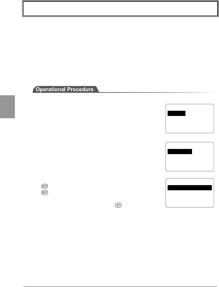
Chapter 4 Settings
4-16
Chap.
4
4-6 Network Menu
This section describes how to set up the CTR-800-11W wireless and TCP/IP
communications.
4-6-1 Wireless Communications Setup
This section describes how to set up the CTR-800-11W for wireless
communications with an access point.
4-6-1-1 Operation Setup
1. From the "System Menu, select "2:Network."
2. Then select "1:RF."
3. Then select "1:Basic."
4. Select the item you want to setup, then press the
key. If you have entered a new value, press the
key to confirm the value.
When setting the SSID, if the key is pressed,
alphabetic characters can be entered.
If the trigger key is pressed, the setup can be done by scanning a barcode.
< Basic Option >
1:SSID
2:Roaming NORMAL
3:DOZE Timeout 05
4:Tx speed Auto
< Network Config >
1:RF 5:DNS
2:TCP/IP 6:SNMP
3:DHCP 7:MAC
4:FTP
< RF Setup >
1:Basic
2:Security
3:Advanced

4-6 Network Menu
4-17
Chap.
4
■SSID Setup
Note the following when setting the SSID. The SSID can incorporate up to 32
characters consisting of single byte alphanumeric character and symbol. The
characters are case sensitive. Automatic setup is possible when the DHCP
function (P.4-23) s enabled. However, since use of the DHCP function creates a
security weak point, please do not use it whenever possible (refer to P.4-18 for
SSID details).
■Roaming level
When a terminal moves around, this function will select an access point
depending on the strength of the wireless signal and changes access points
automatically. This is called roaming. The value which it is compared against
when performing this change is the roaming level. Automatic setup is possible
when the DHCP function (P.4-23) is enabled.
Roaming is only carried out between access points which have the same SSID.
FAST, NORMAL, SLOW
Possible values FAST(roaming is easy) ← NORMAL → SLOW (roaming is hard)
■DOZE timeout
This is the length of time until the wireless component changes to DOZE mode
after transmission has finished. Automatic setup is possible when the DHCP
function (P.4-23) is enabled. The shorter this time is, the longer the battery life
will last, although the wireless response falls.
The response time to power-saving mode varies with the access point beacon
intervals and the DTIM setup. Refer to the access point manual for details.
Possible Settings Instantly, 1, 2, 3, 4, 5, 10 seconds, None
■Transmission speed
Set the Transmission speed. Automatic setup is possible when the DHCP function
(P.4-23) is enabled. Any of the following can be selected.
Auto Transmission speed is changed automatically.
1Mbps Fixed Transmission speed of 1Mbps.
2Mbps Fixed Transmission speed of 2Mbps.
1or2M Transmission speed is automatically changed between only
1Mbps or 2Mbps.
5.5Mbps Fixed Transmission speed of 5.5Mbps
11Mbps Fixed Transmission speed of 11Mbps
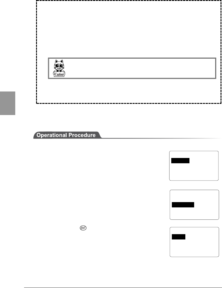
Chapter 4 Settings
4-18
Chap.
4
●SSID (ESSID)
SSID is a unique identifier used to allow a terminal (CTR-800-11W) and
an access point to communicate. Since a terminal can only communicate
with an access point with the same SSID, the risk of a third person
illegally accessing information is reduced a little. When the SSID of a
terminal is set to "ANY" (or with no characters set), the terminal
searches for any available access points automatically and tries to
connect.
Some access point settings may refuse "ANY" settings on
the terminal due to security reason. Refer to the access
point manual for details.
You can set two or more access points to have the same SSID on the
network. This allows roaming of a terminal only between the access
points with the same SSID.
4-6-1-2 Security Setup
1. From the System Menu, select "2:Network."
2. Then select "1:RF."
3. Then select "2:Security."
4. Then press the key.
< Security >
1:WEP
2:AuthenMode OPEN
< Network Config >
1:RF 5:DNS
2:TCP/IP 6:SNMP
3:DHCP 7:MAC
4:FTP
< RF Setup >
1:Basic
2:Security
3:Advanced
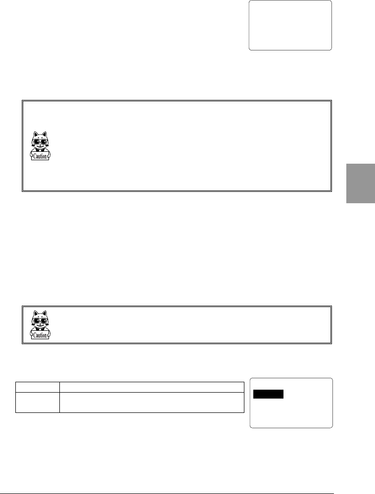
4-6 Network Menu
4-19
Chap.
4
< Authentication >
1:OPEN
2:SHARED
■WEP (refer to P.4-20 for details)
WEP can be set to either "Null," "40 bits," or "128 bits."
●TxKEY_ID
Select the ID used for transmission from KEY1-KEY4 set in the next
paragraph "KEY setup." This becomes effective if the WEP settings are set to
other than "Null."
Communication is possible only if the contents of both the TxKEY_ID WEP key
and the access point WEP key are the same, and if the contents of both the Trans-
mitKEY WEP key set on the access point and the terminal's WEP key are the
same.
For example, when the TxKEY_ID of a terminal is set to "2," the contents of the
terminal WEP key 2 and the contents of the access point WEP key 2 need to be the
same. On the other hand, when an access point TransmitKey is set to "3," the con-
tents of the access point WEP key 3 and the contents of the terminal WEP key 3
need to be the same.
●KEY Setup
Setting the contents of each WEP key (1, 2, 3, 4).
Characters which can be used are "0" - "9", "A" - "F" and "a" - "f." When a 40
bits is selected for "WEP," the WEP is a fixed 10 characters. When 128 bits is
selected, it is a fixed 26 characters. The number of characters that are
actually input is always 26. Therefore, when 40 bits is selected, the first 10
characters of the 26 characters are applied. If a trigger key is pressed, the
setup can be done by scanning a barcode.
Each WEP key setup can be overwritten but cannot be edited.
On entering the KEY setup screen, it displays "00000..." for security purposes.
■Authentication (refer to P.4-20 for details)
OPEN Sets up an "Open Authentication" system.
SHARED Sets up a "Shared Key Authentication"
system.
< WEP >
1:WEP Disable
2:TxKEY_ID KEY1
3:KEY Data
Chapter 4 Settings
4-20
Chap.
4
If the "Shared Key Authentication" system is used, there is a danger that the unen-
crypted and encrypted "challenge code" may be intercepted by a third person. If
this happens, the WEP key can be easily detected. The "Shared Key Authentica-
tion" system thus creates a security weak point and should not be used whenever
possible.
Some access points do not disclose their authentication type. In this case,
please try "Open Authentication," and if connection is impossible, try "Shared
Key Authentication."
●WEP (Wired Equivalent Privacy)
Since IEEE802.11b is a general wireless standard, it may be easily
intercepted by a third person. The danger of data being intercepted
between an access point and a terminal (CTR-800-11W) is avoidable by
using WEP, which is the standard of encryption of wireless-
communication. CTR-800-11W is compliant with two kinds of WEP keys
(common key), "40 bits (also called 64 bits)" and "128 bits."
●Authentication
There are two kinds of authentication systems, "Open Authentication"
and "Shared Key Authentication".
・ "Open Authentication" system
If an authentication request frame from a terminal (CTR-800-11W) is
received, an access point will reply with an authentication response
frame, which will permit data communications.
When WEP is valid, authentication is possible but data
communications cannot be performed if both WEP keys do not
match.
・ "Shared Key Authentication" system
If a terminal performs an authentication request, an access point will
transmit a non-encrypted identity request authentication text
character string (hereinafter called as "challenge code"). Then, the
terminal replies a challenge code encrypted using the WEP key. The
access point decrypts the challenge code via the WEP key and checks
to see if it is the same as the transmitted challenge code and if the
same, permits authentication.
If the challenge code before and after encryption is intercepted by a third
person, the WEP key is easily determined. The "Shared Key Authentica-
tion" system thus creates a security weak point and should not be used
whenever possible.
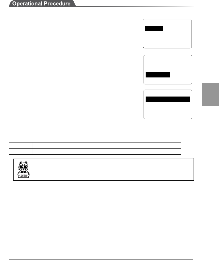
4-6 Network Menu
4-21
Chap.
4
4-6-1-3 Detailed Setup
1. From the System Menu, select "2:Network."
2. Then select "1:RF."
3. Then select "3:Advanced."
■Preamble
Set the preamble.
The preamble is a data part located at head of a wireless
packet. It contains the information that is required for
wireless packet transmission and reception between an access point and a
terminal. "Short preamble" improves the throughput more than "Long
preamble."
LONG Sets a Long preamble.
SHORT Sets a Short preamble.
Some access points may not receive a Short preamble. In this case, please set it to
a Long preamble. Refer to the access point manual for details.
■RTS Threshold
This determines whether an RTS packet is transmitted before transmission of a
data packet. When the size of a data packet is larger than the set value, an RTS
packet is transmitted, and RTS-CTS control is performed. When a large number
of terminals are connected to the same access point, or terminals cannot detect
each other because they are dispersed remotely even if detection of an access
point is possible, RTS-CTS control becomes effective. Although RTS-CTS control
is effective in this case, the throughput reduces. Usually set it to the default value
(2432 bytes).
Possible Setting Range Even value of between 0-3000 bytes
(In the case of odd number, 1 is added)
< Advanced Option >
1:Preamble LONG
2:RTS_Threshold 2432
< Network Config >
1:RF 5:DNS
2:TCP/IP 6:SNMP
3:DHCP 7:MAC
4:FTP
< RF Setup >
1:Basic
2:Security
3:Acvanced
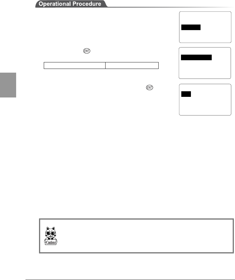
Chapter 4 Settings
4-22
Chap.
4
4-6-2 TCP/IP Setup
Set an IP address and other details for TCP/IP communications. Automatic setup
is possible when the DHCP function (P.4-23) is enabled.
1. From the System Menu, select "2:Network."
2. Then select "2: TCP/IP."
3. To set the value, select the item you want to set up,
then press the key. Then set the value which is
divided into four fields by a period.
Possible Setting Range 0 - 255
Example) 192.168.254.254
4. Once the new value is set, press the key to
confirm the changes.
●IP address
Set the IP address assigned by the network administrator. Set a unique IP
address to each of the CTR-800-11W terminals connected to the same network.
●Subnet mask
Set the subnet mask assigned by the network administrator. Since a subnet
mask specifies which network you belong to, it should set up along with the IP
address.
●Gateway
Set the address of the default gateway. Setup is required when connecting to a
different network through a router.
Please ask the network administrator about the value settings for different items.
When "3:Run at startup" ("4-6-3 DHCP Setup" (P.4-23) s selected, it is only veri-
fied and impossible to change.
< Network Config >
1:RF 5:DNS
2:TCP/IP 6:SNMP
3:DHCP 7:MAC
4:FTP
< TCP
/
IP >
1:IP address
2:Subnet Mask
3:Gateway
< TCP
/
IP >
1:IP>192.168.254.254
2:Subnet Mask
3:Gateway
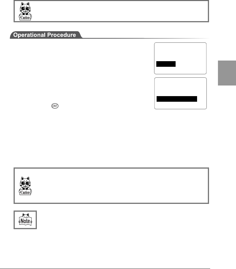
4-6 Network Menu
4-23
Chap.
4
4-6-3 DHCP Setup
Set whether or not the DHCP client function is used for automatic setup of TCP/IP
and various set items. Using the DHCP function, it is possible to download IP
address, server address and program/data files to each CTR-800-11W and set
them automatically.
When you use the DHCP function, "WebGlider" is required.
1. From the System Menu, select "2:Network."
2. Then select "3: DHCP."
●Not use
The DHCP client function is not used, and all parameters
are individually set up for every terminal.
●Run now
By pressing the key, the DHCP request is executed,
the value settings and files are downloaded
automatically. The setup is automatic for the first time only. Select this if nothing
needs to change during operation.
●Run at startup
When the CTR-800-11W is started, a DHCP request is performed and the value
settings and files are downloaded automatically. If you reload programs, data
files and IP addresses regularly, select this operation.
Before selecting "Run now" and "Run at startup", please check that the
"WebGlider" DHCP server is running.
When "3:Run at startup" is selected via the DHCP setup, it becomes impossible to
change the parameter which can be set via "4-6-2 TCP/IP Setup" (P.4-22).
Refer to the "WebGlider" on-line manual for details of setting items via
DHCP.
< Network Config >
1:RF 5:DNS
2:TCP/IP 6:SNMP
3:DHCP 7:MAC
4:FTP
< DHCP Client >
1:Not use
2:Run now
3:Run at startup
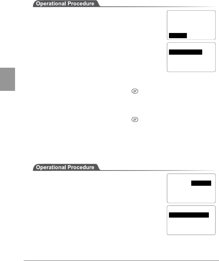
Chapter 4 Settings
4-24
Chap.
4
4-6-4 FTP Setup
Set up for using the FTP client function, as described below. Automatic setup is
possible when the DHCP function (P.4-23) is enabled.
1. From the System Menu, select "2:Network."
2. Then select "4:FTP."
●Host address
Specify The IP address of the FTP server. Automatic
setup is possible when the DHCP function (P.4-23) is
enabled.
●User name
Specify the FTP server login user name using up to 18 alphanumeric characters.
To enter alphabetic characters, press the key.
●Password
Specify the FTP server login password using up to 20 alphanumeric characters.
To enter alphabetic characters, press the key.
4-6-5 DNS Setup
DNS Set the DNS server address, as described below.
Automatic setup is possible when the DHCP function (P.4-23) is enabled.
1. From the System Menu, select "2:Network."
2. Then select "5:DNS."
3. Set the IP addresses for the primary server and
secondary server respectively.
< Network Config >
1:RF 5:DNS
2:TCP/IP 6:SNMP
3:DHCP 7:MAC
4:FTP
< FTP Client >
1:Host address
2:Username
3:Password
< Network Config >
1:RF 5:DNS
2:TCP/IP 6:SNMP
3:DHCP 7:MAC
4:FTP
< DNS >
1:Primary Server
2:Secondary Server
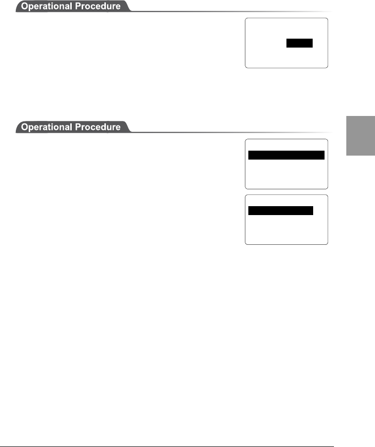
4-6 Network Menu
4-25
Chap.
4
4-6-6 SNMP Setup
Make the various SNMP settings. Automatic setup is possible when the DHCP
function (P.4-23) is enabled.
1. From the System Menu, select "2:Network."
2. Then select "6:SNMP."
■Community (R/Only) Setup
1. From the System Menu, select "2:Network."
2. Then select "6:SNMP."
3. Then select "1:Community(R/Only)."
●Community name
The operations permitted for a community name are
read only. GET and GET-NEXT requests are supported
under a community name.
When a SET request is sent using a community name, an authentication trap is
transmitted.
A community name can be specified using a maximum of 16 alphanumeric
characters.
●Manager address
Set the SNMP manager's IP address, which permits the use of the community
name set under the "Community name" option.
If "000.000.000.000" is set as the SNMP manager's IP address, this community
name is permitted on all the SNMP managers.
< Network Config >
1:RF 5:DNS
2:TCP/IP 6:SNMP
3:DHCP 7:MAC
4:FTP
< SNMP >
1:Community(R/Only)
2:Community(R/W)
3:Trap
< R
/
O Community >
1:Community Name
2:Manager Address
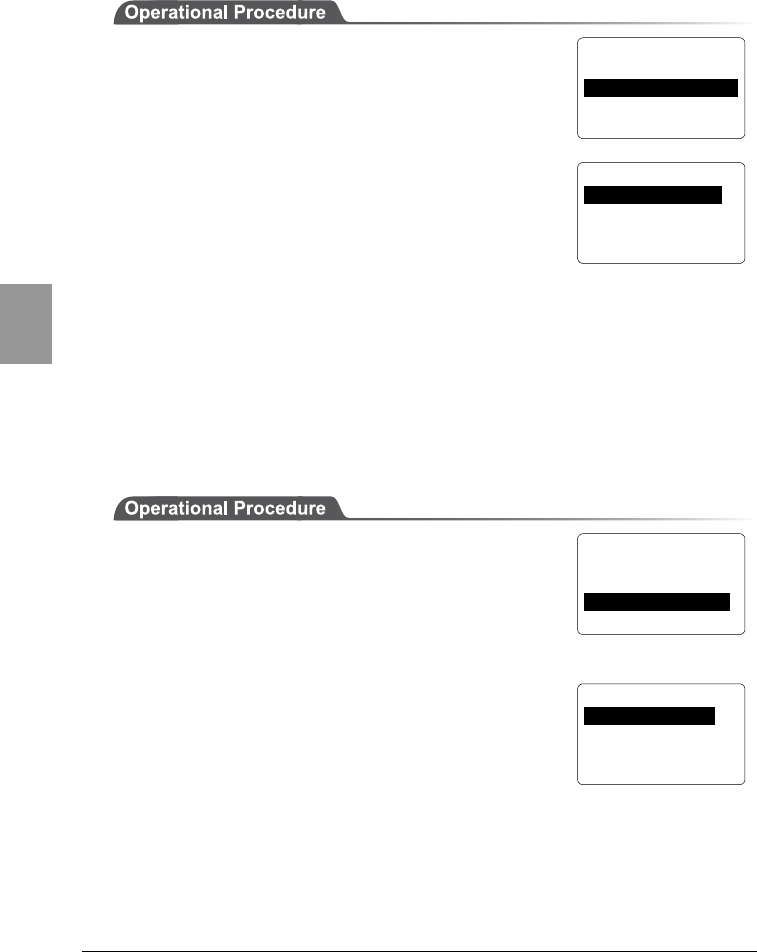
Chapter 4 Settings
4-26
Chap.
4
■Community (R/W) Setup
1. From the System Menu, select "2:Network."
2. Then select "6:SNMP."
3. Then select "2:Community (R/W)."
●Community name
The operations permitted for a community name are
read/write. GET, GET-NEXT and SET requests are
supported under a community name. A community
name can be specified using a maximum of 16
alphanumeric characters.
●Manager address
Set the SNMP manager's IP address, which permits the use of the community
name set under the "Community name" option.
If "000.000.000.000" is set as the IP address, this community name is permitted
on all the SNMP managers.
■Trap Setup
1. From the System Menu, select "2:Network."
2. Then select "6:SNMP."
3. Then select "3:Trap."
●Community name
Set a community name for the Trap.
A community name can be specified using a maximum
of 16 alphanumeric characters.
●Target Address
Set the SNMP manager's IP address to which the Trap should be transmitted.
Trap is not transmitted if the IP address of "000.000.000.000" has been set.
< SNMP >
1:Community(R/Only)
2:Community(R/W)
3:Trap
< SNMP >
1:Community(R/Only)
2:Community(R/W)
3:Trap
< R
/
W Community >
1:Community Name
2:Manager Address
<SNMP Trap >
1:Community Name
2:Target Address
3:Authentication

4-6 Network Menu
4-27
Chap.
4
●Authentication
Set the action of authentication trap to either "send" or "don't send" when access
is recognized except from the community name and SNMP manager's IP address
set in "1: Community (R/Only)" and "2: Community (R/W)."
This Trap is sent to the SNMP manager which is set in "2:Target address."
■About SNMP
・The CTR-800-11W can be managed by using Our "WebGlider" (WBG-
800-01W).
・SNMP-PDU(Protocol Data Unit)conforms to SNMPv1.
・The CTR-800-11W manages the following various MIB group objects.
However, because of the CTR-800-11W's functionality, non-supported
objects are included in the following group.
[1.3.6.1.2.1.1] MIB2-System
[1.3.6.1.2.1.2] MIB2-Interfaces
[1.3.6.1.2.1.4] MIB2-IP *1
[1.3.6.1.2.1.5] MIB2-ICMP *1
[1.3.6.1.2.1.6] MIB2-TCP
[1.3.6.1.2.1.7] MIB2-UDP
[1.3.6.1.2.1.11] MIB2-SNMP *1
[1.3.6.1.4.1.12392] Welcat Enterprise MIB
*1 Non-supported objects are included due to
the functional reason of the CTR-800-11W.
Welcat Enterprise MIB is described in ASN.1
format.
Welcat Enterprise MIB is included in the
optional "WebGlider" (for details, please
contact our sales department).
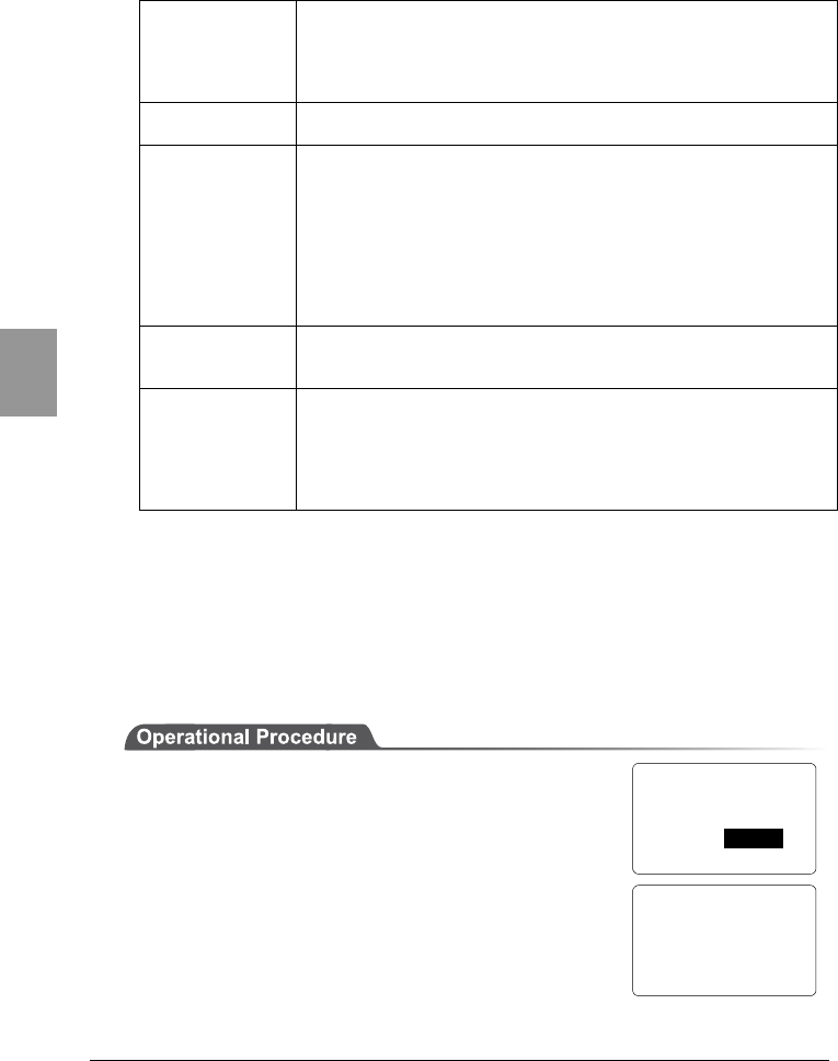
Chapter 4 Settings
4-28
Chap.
4
●Supported Traps
Cold Start Transmitted after MIB is initialized and the communications
starts. MIB is initialized when the CTR-800-11W has been
turned ON using the PW key. Note that MIB is not initialized
when the CTR-800-11W has been turned ON in the resume
mode.
Warm Start Transmitted when communication starts except Cold Start.
*2
Link up Transmitted when CTR-800-11W synchronizes with an
access point. However, a Link Up is not transmitted when
the CTR-800-11W synchronizes with an access point for the
first time (When a Cold Start or a Warm Start is
transmitted). When the CTR-800-11W newly enters a
service area of an access point and synchronizes, or when it
synchronizes with a new access point while roaming, a Link
Up is transmitted (in the same timing as signal
SIGRFU_INSYNC).
Link down Transmitted when the communication ends. However, it is
not transmitted when the CTR-800-11W is outside the
service area of an access point.
Authentication Transmitted when a third person tries to access the CTR-
800-11W with an invalid community. This authentication
trap is sent to the IP address set through the System Menu
"Trap Manager IP address" (P.4-26). However, this is
transmitted only when the value "send" is set through the
System Menu "Illegal access Trap" (P.4-27).
*2 MIB is not initialized even if the "CTR-800-11W" setup corresponding to MIB (IP
address, subnet mask, default gateway, etc.) has been changed. In this case, a
Warm Start is transmitted instead of a Cold Start.
When initializing MIB, cancel the resume mode then turn ON the power.
4-6-7 Displaying the MAC Address
You can display the MAC address (unique hardware address) of the CTR-800-
11W. This address cannot be changed.
1. From the System Menu, select "2:Network."
2. Then select "7:MAC."
< Network Config >
1:RF 5:DNS
2:TCP/IP 6:SNMP
3:DHCP 7:MAC
4:FTP
< MAC address >
[00C0740208D5]
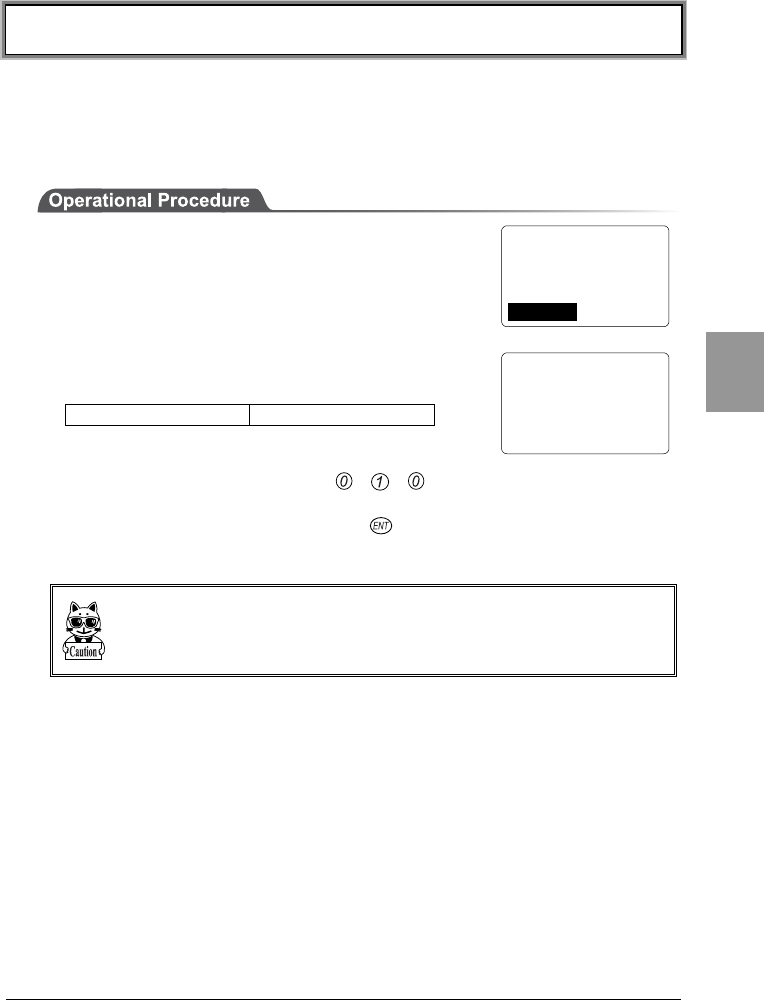
4-7 Terminal ID Setup Menu
4-29
Chap.
4
4-7 Terminal ID Setup Menu
Set up the terminal ID of the CTR-800-11W, as described below. The Terminal
ID should be set to a unique number for every terminal in both wireless network
communications and "Welfer II" serial communications. When the DHCP function
(P.4-23) is enabled, this setup can be made automatically.
1. From the System Menu, select "3:TermID."
2. Set the identification number using any combination
of three numbers.
Possible Setting Range 000 ∼ 999
For example, if you want to set the terminal ID to
010, press the keys in the order , , .
Once the new value is set, press the key to confirm the change.
When using "Welfer II for Windows" for serial communications, it only recognizes
the last 2 digits of the terminal ID. Keep in mind that a terminal ID of "910" and
"010" are recognized as the same ID "10."
< Terminal ID >
ID: 999
< System Menu >
1:System 4:File
2:Network 5:Status
3:TermID 6:Test
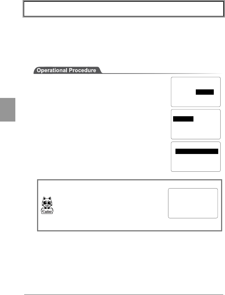
Chapter 4 Settings
4-30
Chap.
4
4-8 File Menu
Use this menu to perform various file operations such as file execution,
transmission and reception, and displaying file information.
4-8-1 Starting an Application
Any application can be started while the System Menu is running.
1. From the System Menu, select "4:File."
2. Then select "1:Execute."
3. When an application is selected, it will then start.
Before the application is started, the file system may
rearrange the files.
The rearrangement process may take between sever-
al seconds up to several minutes. During this time,
do NOT remove the battery pack. If the battery pack
is removed, the data on the drive will become cor-
rupted.
< File Menu >
1:Execute 5:Test
2:Send 6:Property
3:Receive 7:Drive
4:Delete 8:Font
< Select Program >
F:WEB811S.OUT 200K
< System Menu >
1:System 4:File
2:Network 5:Status
3:TermID 6:Test
< File Relocation >
Getting ready for
execution.
DON'T REMOVE BATTERY
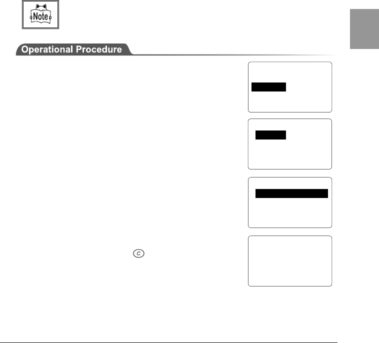
4-8 File Menu
4-31
Chap.
4
4-8-2 Transmitting Files
■Transmitting Files via Wireless Communications
Files can be transmitted via wireless communication from the CTR-800-11W to a
host computer through an access point. Communication is performed using the
FTP protocol.
Before transmitting a file, please check the following.
・Have the wireless-communications parameters (P.4-18) been set up correctly?
・Have the Access Point and host computer been set up and connected correctly?
・Has the FTP been set up (P. 4-21) correctly?
・Is the power of the access point and the host computer on?
・Is the access point operating normally?
・Has the FTP server started on the host computer?
Refer to the access point (our recommended item) manual for details about the
wireless network structure.
1. Turn ON the power of the CTR-800-11W and select
"4:File" from the "System Menu."
2. Then select "2:Send."
3. From the "Select Interface" select "1:RF."
4. Select a file to transmit and transmit the file.
5. When a message indicating that the file was
transmitted successfully is shown on the CTR-800-
11W screen, press the key to return to the
previous screen.
< File Menu >
1:Execute 5:Test
2:Send 6:Property
3:Receive 7:Drive
4:Delete 8:Font
< Select Interface >
1:RF
2:IrDA
3:RS232C
< Select File >
S:SAMPLE01.DAT 10K
S:SAMPLE02.DAT 15K
S:SAMPLE03.DAT 25K
< Send File >
S:SAMPLE01.DAT
Complete !
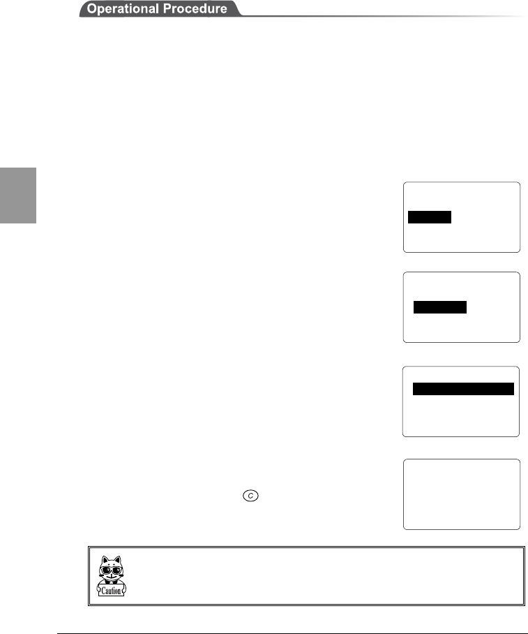
Chapter 4 Settings
4-32
Chap.
4
■Transmitting Files via Serial Communication
Transmitting a file from the CTR-800-11W to the host computer using "Welfer II
for Windows", as follows.
1. Start the host computer in which "Welfer II for Windows" is installed.
2. Turn ON the power of the communication cradle after connecting the
communication cradle (HIF-51) to the host computer using the HIF-51 PC
connection cable (WRS-AXC003A) (P.6-1). When directly connecting the
CTR-800-11W and the host computer together, the PC connection cable
(HOP-C031) is used.
3. Start "Welfer II for Windows" on the host computer.
4. Turn ON the power of the CTR-800-11W and select "4: File" from the System
Menu.
5. Then select "2:Send."
6. Select the method you want to use for transmitting
the file. Select "2:IrDA" when using an
communication cradle to perform infrared
communication. Select "3:RS232C" when the CTR-
800-11W is connected to the host computer directly
using the PC connection cable.
7. Select a file to be transmitted, then transmit the file.
8. When a message indicating that the file was
transmitted successfully is shown on the CTR-800-
11W screen, press the key to return to the
previous screen.
・While transmitting or receiving a file using the communication cradle (HIF-51),
do not remove the CTR-800-11W from the communication cradle.
・When using "Welfer II for Windows" for serial communication, only the last 2
digits of the terminal ID are recognized.
< File Menu >
1:Execute 5:Test
2:Send 6:Property
3:Receive 7:Drive
4:Delete 8:Font
< Select Interface >
1:RF
2:IrDA
3:RS232C
< Select File >
S:SAMPLE01.DAT 10K
S:SAMPLE02.DAT 15K
S:SAMPLE03.DAT 25K
< Send File >
S:SAMPLE01.DAT
Complete !
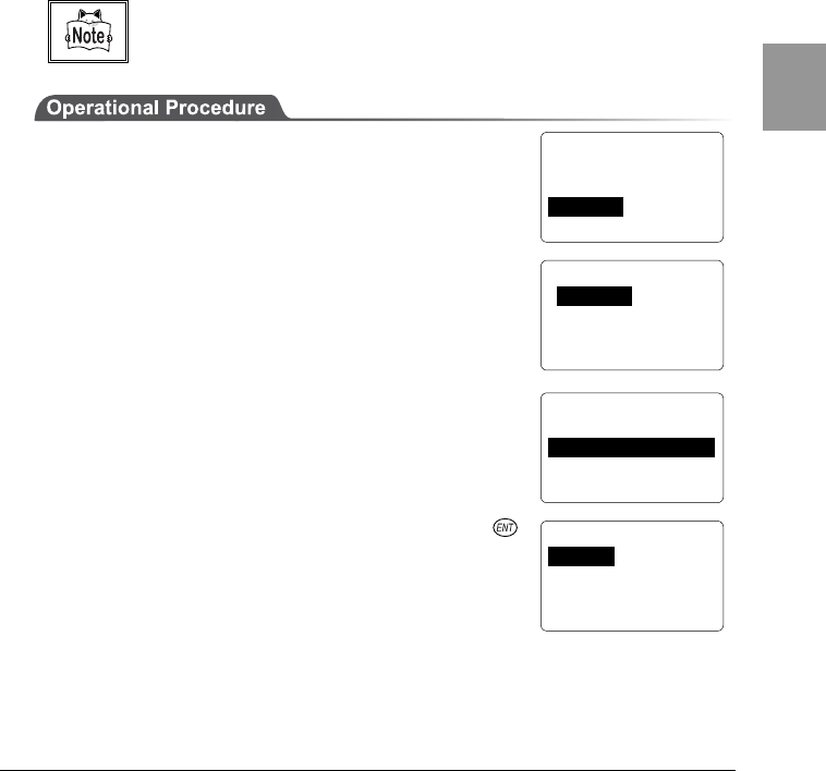
4-8 File Menu
4-33
Chap.
4
4-8-3 Receiving Files
■Receiving files via Wireless Communications
The CTR-800-11W can receive files transmitted from a host computer via an
access point. Communication is performed using the FTP protocol.
Before receiving a file, please check the following.
・Have the wireless-communication parameters (P. 4-16) been set up correctly?
・Have the Access Point and the host computer been set up and connected correctly?
・Has the FTP been set up (P. 4-24) correctly?
・Are the power of the access point and the host computer on?
・Is the access point operating normally?
・Is the FTP server running on the host computer?
Refer to the access point (our recommended item) manual for details about the
wireless network structure.
1. Turn ON the power of the CTR-800-11W and select
"4: File" from the System Menu.
2. Then select "3: Receive."
3. From the File Transmitting Methods, select "1:RF."
4. Select the File storing location. The file list is
automatically retrieved from the FTP server.
5. Select the file you want to receive and press the
key to start downloading.
Any name appended with "<DIR>" is a directory. If a
directory is selected, the file will move to that
directory and the file list will be obtained.
< File Menu >
1:Execute 5:Test
2:Send 6:Property
3:Receive 7:Drive
4:Delete 8:Font
< Select Interface >
1: RF
2: IrDA
3: RS232C
< Select Drive >
1:S_Drive(SRAM)
2:F_Drive(Flash ROM)
< Select File >
..<DIR>
SAMPLE01.dat
SAMPLE02.dat
SAMPLE03.dat
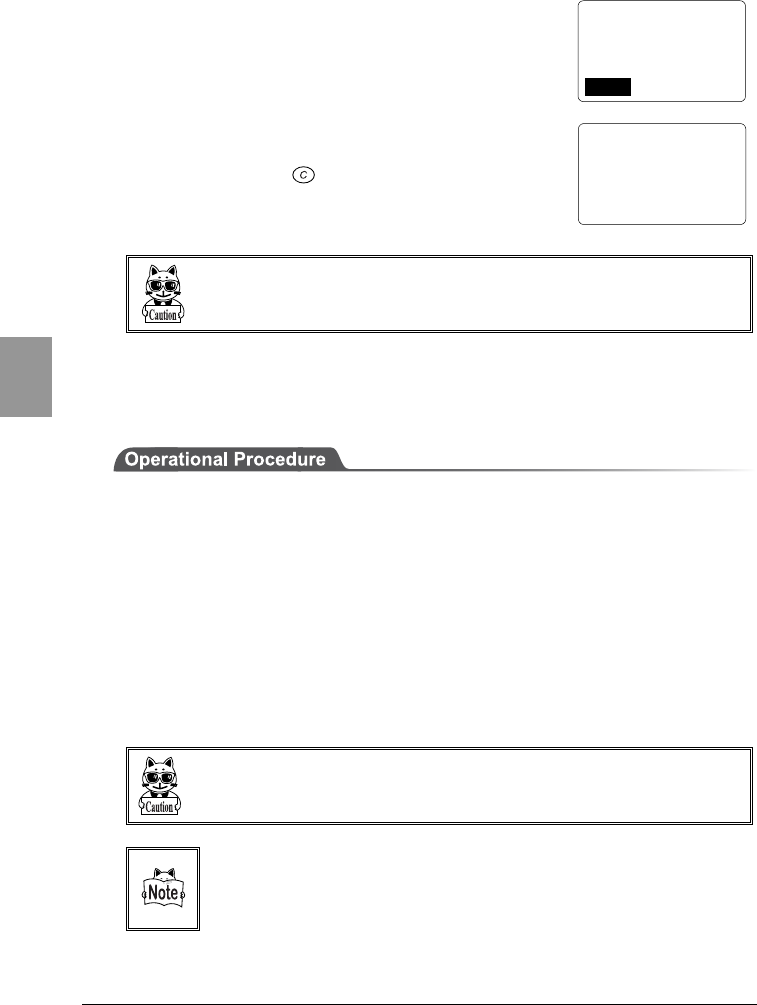
Chapter 4 Settings
4-34
Chap.
4
6. If you want to continue downloading, select "1: YES"
and repeat 5 (when downloading to the S drive).
7. When a message indicating that the file has been
received successfully is shown on the CTR-800-11W
screen, press the key to return to the previous
screen.
Long file names (except for 8.3 naming format) or Japanese (double-byte charac-
ters, kana characters) file names cannot be received. These files are not displayed
on the file list.
■Receiving Files via Serial Communications
Receive a files transmitted from the host computer to the CTR-800-11W, using
"Welfer II for Windows" , as described below.
1. Start the host computer in which "Welfer II for Windows" is installed.
2. Turn ON the power of the communication cradle after connecting the
communication cradle (HIF-51) to the host computer using the HIF-51 PC
connection cable (WRS-AXC003A) (P.6-1).
When directly connecting the CTR-800-11W and the host computer together,
the PC connection cable (HOP-C031) is used.
3. Start “Welfer II for Windows” on the host computer. Select a file to transmit
and enter the two digits representing the terminal ID for CTR-800-11W.
(For the setting method, refer to the manual supplied with "Welfer II for
Windows.")
When using "Welfer II for Windows" for serial communication, only the last 2
digits of the terminal ID are recognized.
When using the communication cradle (HIF-51) via a daisy chain connection,
** should be entered as the terminal ID to allow transmission of one file to
two or more terminals at once (P.6-6) (Broadcast Transmission).
< Receive File >
Complete !
< Receive File >
sample01.dat
Complete !
Continue to receive?
1:Yes 2:No
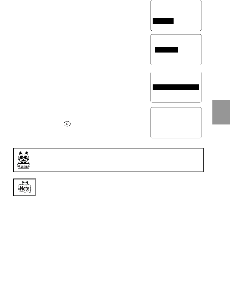
4-8 File Menu
4-35
Chap.
4
4. Turn ON the power of the CTR-800-11W and select
"4:File" from the "System Menu."
5. Then select "3:Receive."
6. Select the method you want to use for receiving the
file. Select "2:IrDA" when using an communication
cradle to performing infrared communication. Select
"3:RS232C" when the CTR-800-11W is connected to
the host computer directly using the PC connection
cable.
7. Select the file storing location. The CTR-800-11W
will then go into a waiting state.
8. Initiate transmission from "Welfer II for Windows" on
the host computer. With this, a download to CTR-
800-11W will start.
9. When a message indicating that the file has been
received successfully is shown on the CTR-800-11W
screen, press the key to return to the previous
screen.
While transmitting or receiving a file using the communication cradle (HIF-51), do
not remove the CTR-800-11W from the communication cradle.
Refer to the software's included manual for information about "Welfer II for
Windows" Communications Setup.
< File Menu >
1:Execute 5:Test
2:Send 6:Property
3:Receive 7:Drive
4:Delete 8:Font
< Select Interface >
1:RF
2:IrDA
3:RS232C
< Select Drive >
1:S_Drive(SRAM)
2:F_Drive(Flash ROM)
< Receive File >
0001000 /0001000
Complete !

Chapter 4 Settings
4-36
Chap.
4
4-8-4 Deleting Files
Delete unnecessary files, as described below.
1. From the System Menu, select "4:File."
2. Then select "4:Delete."
3. Select a file to delete.
4. Select "1:Delete" to delete the file. To cancel, select
"2:Cancel."
< Select File >
F:SAMPLE01.DAT 10K
< File Menu >
1:Execute 5:Test
2:Send 6:Property
3:Receive 7:Drive
4:Delete 8:8Font
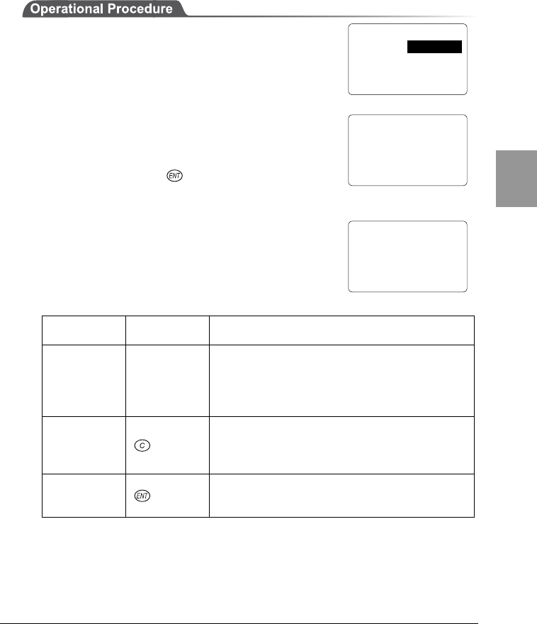
4-8 File Menu
4-37
Chap.
4
4-8-5 Testing Files
Test the stored files to see if any of them are corrupted or not. When this menu
item is selected, a test will be performed automatically on the files stored in the
S Drive.
1. From the System Menu, select "4:File."
2. To start a file test, select "5:Test."
3. When completed, the message screen 1, shown
right, will be displayed.
If a corrupt file is found, a message similar to
message screen 2, shown right, will be displayed in
the middle of the test.
Using the corrupt file as is, may cause the
application to malfunction. If the corrupt file is not
important, press the key to delete it.
Delete the corrupt file, or transmit it to a host
computer so that an appropriate measure can be
taken to restore the contents.
Message Key to
operate Description
(T) : Ignore Scanning
key
This file is deemed normal (even if the
contents are corrupted), and the file test
process will continue. If the test is
performed again on this file, the message in
message screen 2 will not be displayed.
(C) : Leave Key
Nothing is processed. The OS will prompt the
user to choose what to do again next time
the CTR-800-11W is started, a file test is
performed or on other occasions.
(E) : Delete Key
The file is deleted. If the file is not important,
we recommend you to delete the file
whenever possible.
< File Menu >
1:Execute 5:Test
2:Send 6:Property
3:Receive 7:Drive
4:Delete 8:Font
< Test Files >
Complete !
All OK
message screen 1
< Test Files >
S:File2.DAT
This file is broken!
(T):Ignore(E):Delete
(C):Leave
message screen 2
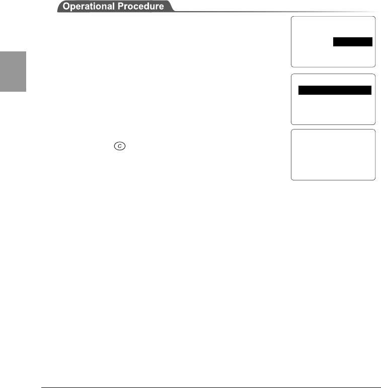
Chapter 4 Settings
4-38
Chap.
4
4-8-6 File Information
To view file information, follow the procedure below. The information retrieved is
as follows.
・File Name
・File Type
・File Size
・Date on which the file was last modified
(Year/Month/Day/Hour/Minute/Second)
1. From the System Menu, select "4:File."
2. Select "6:Information."
3. Select a file.
4. The information of the selected file is displayed.
Press the key to return to the previous screen.
< File Menu >
1:Execute 5:Test
2:Send 6:Property
3:Receive 7:Drive
4:Delete 8:Font
< Select File >
S:SAMPLE01.DAT 10K
S:SAMPLE02.DAT 15K
S:SAMPLE03.DAT 20K
<S:SAMPLE01.DAT>
Type: Data file
Size: 10240 Byte
Date: 2002/04/01
04:15:24
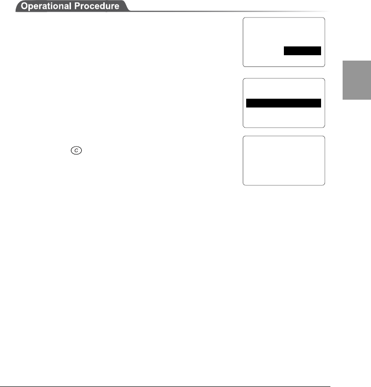
4-8 File Menu
4-39
Chap.
4
4-8-7 Drive Information
To view the information on a drive you select, follow the procedure below. The
information retrieved is as follows.
・Drive Name
・Maximum capacity for the drive
・Available space on the drive
・The number of files currently stored and the number of files that can be created
1. From the System Menu, select "4:File."
2. Select "7:Drive."
3. Select the drive on which information you want to
view.
4. The information on the selected drive is displayed.
Press the key to return to the previous screen.
< File Menu >
1:Execute 5:Test
2:Send 6:Property
3:Receive 7:Drive
4:Delete 8:Font
< Select Drive >
1:S_Drive(SRAM)
2:F_Drive(Flash ROM)
< Drive Property >
F_Drive
Total: 3276800byte
Free : 3276800byte
Files: 5 Pools:45
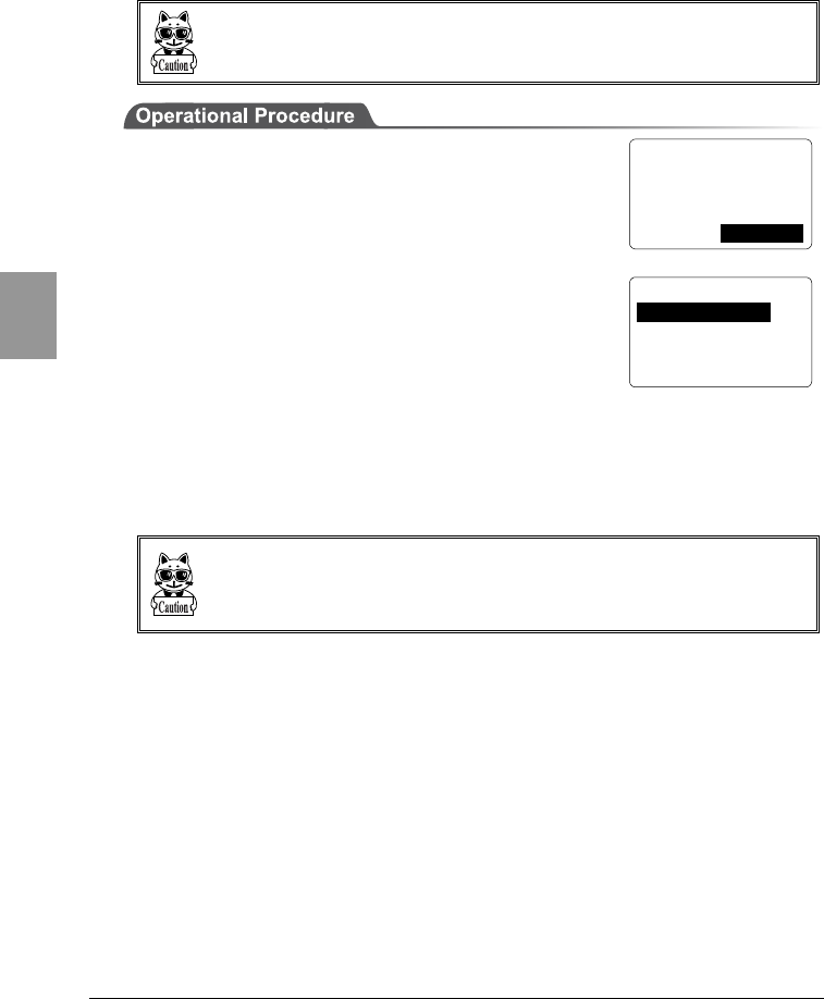
Chapter 4 Settings
4-40
Chap.
4
4-8-8 Changing the Font
If font files are installed, the font used in an application can be changed.
The font used for the System Menu cannot be changed. Only systemt Gothic (12-
dot display) can be used.
1. From the System Menu, select "4:File."
2. Select "8:Font."
3. The current font name is displayed on the bottom
line. "1:System Gothic" is the font used for the
System Menu.
4. To change the current font, select "2:Optional Font"
to display a list of font files. For example, if the 16-
dot Gothic font provided in the CTR-800-11W
model-specific library (HAP-LIB-82, optional) is
loaded, it becomes possible to display 16 -dot fonts.
When using an additional font, the application must
support the font. In the case where an application does not support the
selected font, the application may not work or the screen display may be
distorted.
The extension of a font file is "FNV."
When supplied, the CTR-800-11W does not have any font files (~.FNV). When
you change the font, first download 16-dot Gothic font, etc. included in the CTR-
800-11W model-specific library (HAP-LIB-82, optional) to the F Drive.
< File Menu >
1:Execute 5:Test
2:Send 6:Property
3:Receive 7:Drive
4:Delete 8:Font
< Select Font >
1:System Gothic
2:Optional Font
[System Gothic]
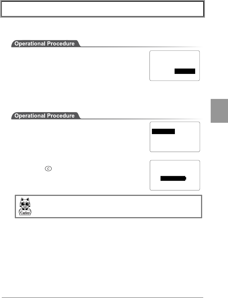
4-9 Status Menu
4-41
Chap.
4
4-9 Status Menu
You can check the information on the CTR-800-11W, as described below.
1. From the System Menu, select "5:Status."
4-9-1 Battery Voltage
To display the voltage level of the battery pack equipped in the CTR-800-11W,
follow the procedure below.
1. From the System Menu, select "5:Status."
2. Then select "1:Battery."
3. The indicator shows the battery pack's voltage level.
Press the key to return to the previous screen.
The level displayed is not the exact battery voltage. Use this level as a guide for
the battery voltage.
< Status >
1:Battery
2:Version
3:Clock
< Battery Status >
L
H
< System Menu >
1:System 4:File
2:Network 5:Status
3:TermID 6:Test
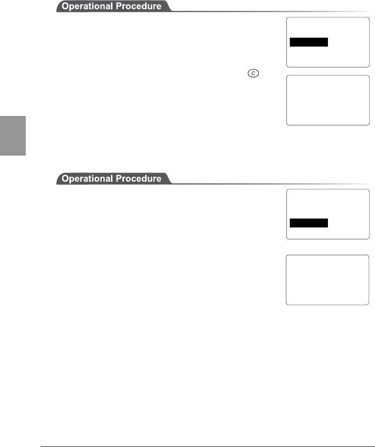
Chapter 4 Settings
4-42
Chap.
4
4-9-2 OS Version
To display the version information of the CTR-800-11W's system program (OS),
follow the procedure below.
1. From the System Menu, select "5:Status."
2. Then select "2:Version."
3. The version number is displayed. Press the key
to return to the previous screen.
4-9-3 Clock
To display the time which was set up through "4-5-3 Clock Setup" (P.4-9) follow
the procedure below.
1. From the System Menu, select "5:Status."
2. Then select "3:Clock."
3. The current time is displayed.
< Status >
1:Battery
2:Version
3:Clock
< System Version >
OS : V1.00E
< Status >
1:Battery
2:Version
3:Clock
< Date
/
Time >
2003 / 07 / 01
02 : 35 : 47
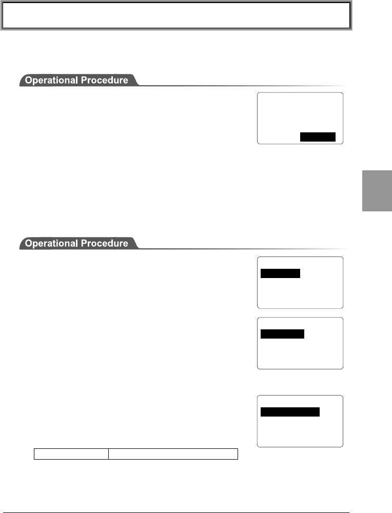
4-10 Test Menu
4-43
Chap.
4
4-10 Test Menu
From this menu, you can perform various tests on the CTR-800-11W's basic
functions.
1. From the System Menu, select "6:Test."
4-10-1 RF Test
Checking the connectivity of the IP network by executing the wireless
communications test and the ping command.
■Conditions Setup
Set up the conditions under which the ping command is executed. A wireless test
is performed by sending the ping command.
1. From the System Menu, select "6:Test."
2. Then select "1:RF."
3. Then select "1:Parameter."
■Conditions Setup
●Host address
Specify the IP address of a device with which a
communication test will be performed.
●Packet size (32bytes by default)
Select the size of the data packet (in bytes) to be
transmitted.
Possible Settings 32, 64, 128, 256, 512, 1024
< System Menu >
1:System 4:File
2:Network 5:Status
3:TermID 6:Test
< Test Menu >
1:RF 5:Key
2:COM
3:Barcode
4:LCD
< RF Test >
1:Parameter
2:Site Survey
3:Ping
4:Search AP
< Ping Parameter >
1:Host address
2:Packet size
3:Timeout
4:Count
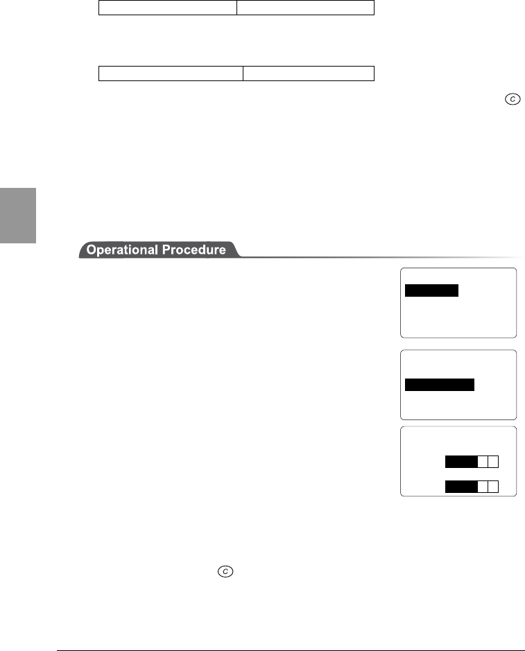
Chapter 4 Settings
4-44
Chap.
4
32B time<30ms
AP_MAC[001122334455]
LnkQ
L
H
CH:01 SPD: 1Mbps
ASL
L
H
●Timeout Period (1 second by default)
Set the Timeout period in seconds.
Possible Setting Range 1 ∼ 255 seconds
●Number of Attempts (4 by default)
Set the number of attempts that can be made at transmitting the ping.
Possible Setting Range 0 ∼ 255 times
If 0 is specified, transmission of the ping command will continue until the
key is pressed.
■RF Test
Perform a wireless test by executing the ping command. The ping command will
be continually transmitted to the host IP address set in "Setup Conditions."
During a wireless test, the result of the ping command, synchronized access
point's MAC Address, the wireless reception level (ASL), the communication
quality (LnkQ), the channel used and transmission speed are displayed.
1. From the System Menu, select "6:Test."
2. Then select "1:RF."
3. Then select "2:Site Survey."
4. The wireless communications test screen is
displayed and the ping communication begins.
The 1st line displays the result of the ping command.
The 2nd line displays the MAC address of the access
point used for wireless communications.
The 3rd line displays the LnkQ indicator showing the
quality of communication with the access point.
The 4th line displays the synchronized channel and the transmission speed.
The 5th line displays the ASL indicator showing the level of incoming signal
strength from the access point.
To cancel, press the key.
< Test Menu >
1:RF 5:Key
2:COM
3:Barcode
4:LCD
< RF Test >
1:Parameter
2:Site Survey
3:Ping
4:Search AP
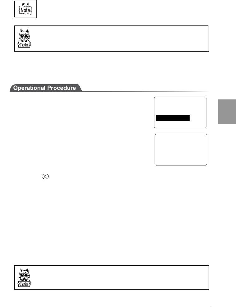
4-10 Test Menu
4-45
Chap.
4
For stable communication performance, we recommended that you use the
CTR-800-11W at locations where the LnkQ indicates 4 or more.
The LnkQ displayed on the 3rd line and the ASL Indicator displayed on the 5th
line do not represent the exact levels of incoming signal strength. Use these levels
only as a guide for the wireless reception level.
■Executing the Ping
To execute the ping command under the conditions that you have set up, follow
the procedure below.
1. From the System Menu, select "6:Test."
2. Then select "1:RF."
3. Then select "3:Ping."
・The response time (turnaround time) is displayed for
every packet transmitted and received.
・"Timeout" will be displayed if a response has not
been received within the timeout period.
・If 0 is specified as the number of trials, the
transmission of the ping command will be performed
until the key is pressed.
■Searching for Access Points
To start a search for available access points, follow the procedure below. The
search function searches for access points which have the same SSID as the
SSID set through the "■SSID Setup" (P.4-17). If the value "ANY" (or no
character) has been set, a search will be made for any available access points
regardless of the SSID.
In the results shown, the access point MAC addresses and synchronous channels
are listed in descending order of communication quality for channels
synchronized with the access point MAC addresses. The maximum number of
access points, which can be displayed is 35.
Depending on the access point setup, "SSID" information may not be transmitted
for security reasons. If this is the case, an access point will not be found.
< ping >
32B time<Timeout
32B time<40ms
32B time<40ms
32B time<50ms
< RF Test >
1:Parameter
2:Site Survey
3:Ping
4:Search AP
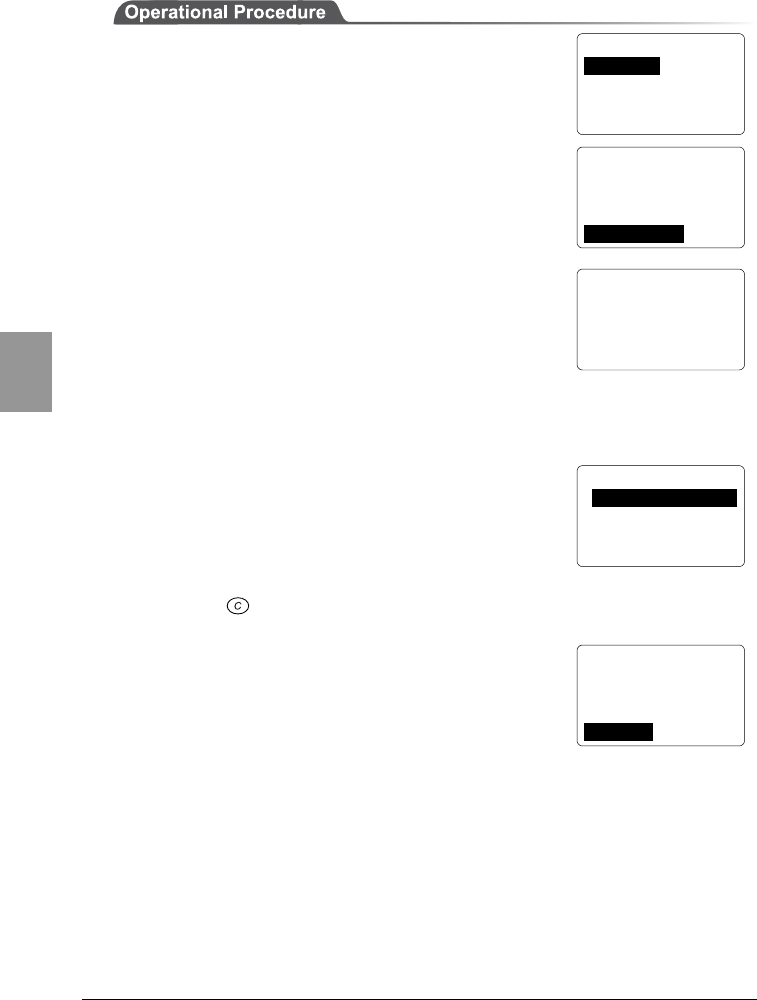
Chapter 4 Settings
4-46
Chap.
4
< Test Menu >
1:RF 5:Key
2:COM
3:Barcode
4:LCD
< RF Test >
1:Parameter
2:Site Survey
3:Ping
4:Serarch AP
< Search AP >
Target SSID =
ANY
Search Access Ponit..
< AP Search Result >
00A0F850D7D3 01
00A0F850D7F4 06
00A0F850D7CE 11
< AP Property >
MAC[00A0F850D7D3]
SSID = 80011
1:Survey 2:Select
1. From the System Menu, select "6:Test."
2. Then select "1:RF."
3. Then select "4:Search AP."
4. A search for access points will be started. The SSID
that has been set through the "■SSID Setup" (P.4-
17) is displayed on the lines 3 and 4 on the screen,
and an access point with the same SSID setup will be
searched. If the value "ANY" (or no character) has
been set, any available access point will be searched
regardless of the SSID.
5. The access point search results are displayed. In the
results shown, the access point MAC addresses and
synchronous channels are listed in descending order
of communication quality. Once an access point is
selected from the search results, the SSID of that
access point can be obtained. A wireless test can be
performed with the access point only.
Press the key to return to 3.
6. The SSID of the selected access point is displayed
(the SSID in the image shown right is "80011").
Select "1:RF" to initiate a wireless test with the
selected access point only. To perform this test, the
"■Conditions Setup" (P.4-43) must have been
completed.
Selecting "2:Select" will set up the SSID with the character string displayed
here.
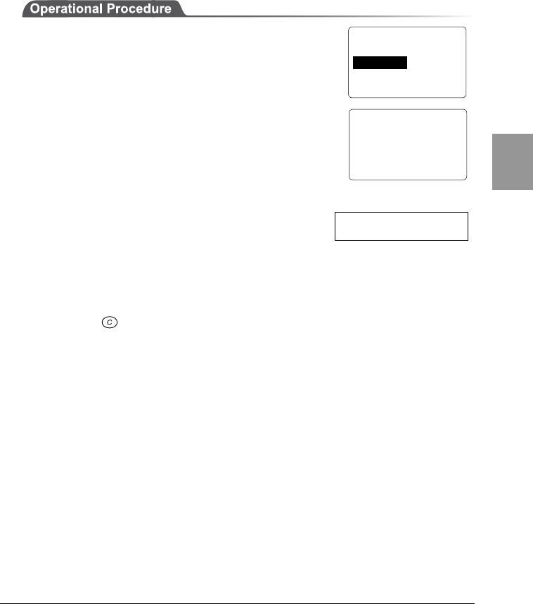
4-10 Test Menu
4-47
Chap.
4
4-10-2 Serial Communication Test
Perform a serial communications test on the CTR-800-11W, as described below.
To run the test, preparation for data communication is required. For details, refer
to "1-4 Preparation for Data Communication" (P.1-9), or "4-5-2 Serial
Communication Setup" (P.4-8) as appropriate.
1. Connect the CTR-800-11W to the host computer
using the PC connection cable (HOP-C031).
2. On the host computer, start any communication
software (hyper-terminal etc.). Set up the
communication software to have the same
communication settings as the CTR-800-11W.
3. From the System Menu, select "6:Test."
4. Then select "2:COM."
In serial communications, a loopback test is
performed. When you enter any character using
the host computer keyboard, the same character
will be displayed on the CTR-800-11W screen. If
"local echo" is set on the communication software
side, the character entered using the keyboard
can be verified also on the host computer.(Refer to the screen example.)
When the CTR-800-11W is directly connected to the host computer via the PC
connection cable (HOP-C031), every character entered will display twice on
the host computer screen.
5. Press the key to return to the screen immediately before the test.
< COM Test >
abcdefg
●Screen example
>aabbccddeeffgg
< Test Menu >
1:RF 5:KEY
2:COM
3:Barcode
4:LCD
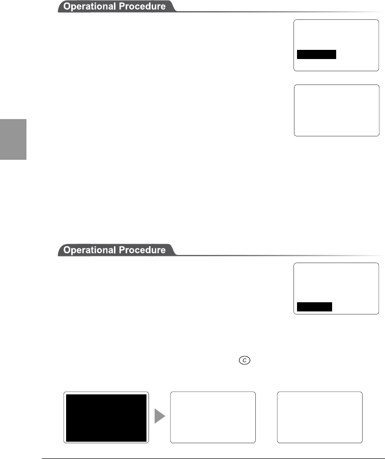
Chapter 4 Settings
4-48
Chap.
4
4-10-3 Barcode Scanning test
Perform a barcode scanning test, as described below. A sample barcode can be
found in "Sample Barcode" (Appendix B-2).
1. From the System Menu, select "6:Test."
2. Then select "3:Barcode."
3. Press the scan key to scan the barcode. The scan
result is displayed on the screen, similar to the
image shown right.
The scanned barcode is displayed on the 2nd line.
The type and the number of digits of the scanned
barcode are displayed on the bottom line. If you hold
down the scan key for approximately 1 second, the continuous scanning
mode will be enabled. Scanning will continue until you release the scan key,
and the success rate will be displayed in the bottom right of the screen.
If the trigger mode or the power save mode is set, it will not affect the
continuous scanning.
4-10-4 Screen Display Test
Perform a screen display test, as described below.
1. From the System Menu, select "6:Test."
2. Then select "4:LCD"
3. The backlight is turned ON and the whole screen is
filled in. If any keys are pressed, the corresponding characters will be
displayed on the screen in sequence. If the scan key is pressed, the test will
stop with the screen displaying where the test stopped. The test will resume
if the scan key is pressed again. If the key is pressed, the test will be
aborted and the CTR-800-11W will return to the screen immediately before
the test.
< Barcode Test >
4994121104579
JAN13 L:13 100%
、。,.・:;?!
゛゜´`¨^ ̄_ヽヾ
ゝゞ〃仝々〆〇ー―‐
/\~∥|…‥‘’“
”()〔〕[]{}〈
こ
ご
さ
ざ
しじ
すず
せ
ぜ
そぞただちぢっつづて
でとどなにぬねのはば
ぱひびぴふぶぷへべぺ
ほぼぽまみむめもゃや
……
< Test Menu >
1:RF 5:KEY
2:COM
3:Barcode
4:LCD
< Test Menu >
1:RF 5:KEY
2:COM
3:Barcode
4:LCD
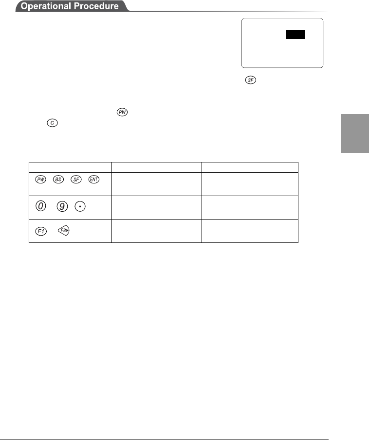
4-10 Test Menu
4-49
Chap.
4
4-10-5 Key Input Test
To perform a key input test, follow the procedure below. Along with this test,
tests on the buzzer, vibration, and LED light are also performed.
1. From the System Menu, select "6:Test."
2. Then select "5:Key."
3. The test screen is displayed. If any key is pressed,
the key's mark will be displayed on the screen. If the key is held down
and any key is pressed, the mark will be highlighted. Also, no matter which
key is pressed, the buzzer and vibrator will be tested.
During the test, if the is pressed, the power will not be turned OFF. Press
the key to return to the screen before the test.
The LED light test is also performed according to the key pressed. Refer to the
following table for information about the LED color-key correlation.
Key Scanning LED color Warning LED Color
Scan key Orange Red
~ Green ---
~Red ---
< Test Menu >
1:RF 5:KEY
2:COM
3:Barcode
4:LCD
Chapter 4 Settings
4-50
Chap.
4
4-11 Other Functions
4-11-1 Low Voltage Warning
If the voltage level of the equipped battery pack decreases, it becomes
impossible to perform the following operations with the System Menu.
・Launch of applications
・File transmission, reception, deletion and test
・Clock setup
If any of the operations mentioned above is performed
when the voltage level of the battery pack is low, the
screen, similar to the image shown right, will be
displayed.
At this time, [Battery Low] is displayed on the 2nd line of
the screen, and CTR-800-11W will beep 3 times for
warning.
Even if the voltage level of the battery pack is low,
operations of the System Menu other than those above
can be performed.
Also, when the CTR-800-11W judges that the voltage level is less than the
regulation level, it displays a message on the screen, shown right, for 5 seconds
while sounding short beeps, and then shuts down automatically.
4-11-2 Auto-power-off
Through the System Menu, if no key operation is performed for approximately 10
minutes, the power shuts off automatically.
This function may also be incorporated into an application. Refer to the applica-
tions manual for details.
[
Batterey Low
]
Change battery pack!
< File Menu >
[ Battery Low ]
You can't finish
this operation.
Change battery pack!
4-12 Initialization of the CTR-800-11W
4-51
Chap.
4
4-12 Initialization of the CTR-800-11W
While using the CTR-800-11W, the contents in the memory storage area may be
corrupted for some reasons and the CTR-800-11W may not operate normally.
Although almost all those abnormalities are corrected automatically through the
System Menu, a serious error may not be able to be corrected.
In such a case, internal memory can be erased using the following method. This
will reset the CTR-800-11W back to factory settings.
Refer to "Appendix A - System Menu, Factory Settings" (Appendix A-2) for
information about the System Menu factory settings.
Be careful when performing this operation since this operation will erase the Sys-
tem Menu setup and any data or programs saved in the CTR-800-11W. Also, when
you perform this operation, turn OFF the suspend mode.
■Initialization of the "System Menu"
1. Turn OFF the power of the CTR-800-11W.
2. Press the scan key, key and the key simultaneously. Then press the
key. Then press the PW key. The System Menu will be initialized and
reboot.
Using this function, all the System Menu setup is initialized. The files saved on
the CTR-800-11W are not erased.
Chapter 4 Settings
4-52
Chap.
4
■Full Initialization
This function will erase all files and applications except the OS from the CTR-
800-11W. The "CTR-800 browser" installed at the time of purchase is
also erased. Make sure to back up everything before initialization.
Prepare a fully charged battery pack before performing a full initialization. Also,
do not remove the battery pack during this process. A full initialization takes ap-
proximately 7 to 10 minutes. No keys can be entered during this procedure. If the
battery pack is discharged or removed during the initialization process, the initiali-
zation is performed incompletely and the CTR-800-11W data area may be cor-
rupted.
1. Turn OFF the power of the CTR-800-11W.
2. Press the key, key and the key simultaneously and press the
key. After displaying a confirmation message, the CTR-800-11W will be
initialized.
■Maintenance Notes
Please note that the CTR-800-11W will be fully initialized at the time of mainte-
nance or checkup. Although the "CTR-800 browser" is reinstalled before return-
ing, your created files cannot be reinstalled. We recommend that a backup be
taken.

Chapter 5
5 FAQ
Chapter 5 FAQ
5-2
Chap.
3
5-1 FAQ (Frequently Asked Questions)
This chapter lists frequently asked questions, problems and operations that need
to be performed to solve problems, and reference pages for items in this manual.
Q: The power does not turn ON.
■Is the battery pack equipped correctly? ---- (P.2-11)
■Is the battery pack charged?---- (P.2-9)
■Aren't the battery pack electrodes dirty? ---- (P.2-9)
Q: Nothing is displayed on the screen.
■Is the battery pack equipped correctly? ---- (P.2-11)
■Is the battery pack charged?---- (P.2-9)
■Aren't the battery pack electrodes dirty? ---- (P.2-9)
<In the case where the items mentioned above have been checked and the problem
is still unsolved>
Please start the system menu using the following method.
Remove the battery pack → Wait 10 seconds → Install the battery pack → Hold down the
scan key then press the key.
If the problem persists even after using the method above, turn OFF the
power, hold down the , and scan key together then press the key.
This will initialize the System Menu. ---- (P.4-51)
Q: After not using for a while, the power is shut OFF.
■Is the battery pack charged?---- (P.2-9)
■Hasn't the Auto-power-off function been set to start?---- (P.4-50)
Q: It cannot charge.
■Has the charger been equipped with the battery pack correctly?
Please refer to the instruction manual included in the "Battery pack HBC-51/54
dedicated charger HQC-51/54" for information on charging the battery pack.

Chapter 5 FAQ
5-3
Chap.
5
Q: The System Menu does not start.
■Is an "User Program" not set to "Startup"? ---- (P.4-7)
From the System Menu, select "1:System", then "1:Startup" to set the System
Menu for automatic launch.
■To force the launch of the System Menu, hold the scan key then press the
key. ---- (P.4-5)
Q: How do I change the application which starts
when the power is turned ON?
From the System Menu, select "1:System", then "1:Startup" to set the
desired application for automatic launch. ---- (P.4-7)
Q: How do I start another application?
From the System Menu, select "4:File" then "1:Execute" then select an
application to run. ---- (P.4-30)
Q: The barcode is not scanned successfully.
■Does the scanned bar code meet the barcode settings set in the
application?
Some application settings prohibit a specific kind of barcode from being scanned.
■Isn't specular reflection occurring? ---- (P.2-7)
■Is scanning distance correct?---- (P.2-6)
■Isn't the filter of the barcode sensor dirty? ---- (P.1-4)
If the filter of the barcode sensor is dirty, the bar code may not be scanned
correctly. Please wipe the filter with a dry soft cloth.
Q: How do I check the free area of a drive?
From the System Menu, select "4:File" then select "7:Drive" to check the
drive.---- (P.4-39)

Chapter 5 FAQ
5-4
Chap.
3
Q: I cannot perform wireless data communications.
■Is the access point connected to the Ethernet LAN?
・If the LAN cable has fallen out or a link is not established, some access
points do not perform wireless communications.
<When the Warning LED lights ON>
■Is terminal SSID setting the same as the access point SSID settings? --
-- (P.4-17)
Please set the access point SSID and terminal SSID the same.
When the terminal SSID is set to "ANY" (blank), it may be unable to connect
because of the access point functions. Refer to the access point manual for more
information.
■Is the authentication setup correct? ---- (P.4-19)
Please set the access point Authentication System and terminal Authentication
System settings the same.
If in "SHARED" mode, please check the WEP settings.
■Please check the Preamble settings. ---- (P.4-21)
If the terminal's Preamble is set to "SHORT," is the access point not set to "LONG"
or something not compliant with "SHORT"?
<When Warning LED turns off or blinks>
■Are the WEP settings the same?
Are the WEP Keys the same? ("Null," "40bits," "128bits")
Do the WEP's TxKEY_ID and the WEP key match? (P.4-19)
■Doesn't an access point with a same channel or interfering channel exist?
In the case where a non-interfering channel is set, a maximum of 4 access points
can be used in the one area.
■Isn't the wireless transmission being interfered by an obstacle?
Please check whether there is no equipment, such as a microwave oven or other
WLANs etc, which can cause interference.
Also, since a computer may act as a noise generation source, move the access
point and terminal away from the computer (1m or more).
■Aren't there any problems with the TCP/IP settings (IP address etc)?--
-- (P.4-22)
Check it to see if the terminal can connect to the computer by using the ping
command etc.

Chapter 5 FAQ
5-5
Chap.
5
Q: Data communications cannot be performed via
IrDA or RS-232C.
■Is each piece of equipment connected correctly?
・Connection between the CTR-800-11W and the PC---- (P.1-5)
Use the PC connection cable (HOP-C031).
・Connection between the communication cradle (HIF-51) and the PC--
-- (P.1-5)
Use of daisy chain connection for the communication cradle (HIF-51)
・Use of daisy chain connection for the communication cradle (HIF-51)--
-- (P.6-6)
Use the daisy chain connection cable (STP-C001A).
■Has the serial communication settings been set correctly? ---- (P.4-8)
■Are the communication cradle and computer connected correctly?
■When using a daisy chain connection, have the communication cradle
(HIF-51) DIP switches been set correctly?---- (P. 6-6)
■Isn't the CTR-800-11W IrDA interface or the communication cradle
(HIF-51) IrDA interface dirty? ---- (P.1-4)
If the IrDA interface is dirty, IrDA communication may not be performed
correctly. Please wipe the interface with a dry soft cloth.
Q: "Writing Failed" was displayed during transmis-
sion or reception of a file.
■This message is displayed when there is little space left on the S Drive.
It is displayed when there is little space left on the S Drive. ---- (P.3-3, 4-36)
When you use the F Drive to receive files, the CTR-800-11W requires the S drive
to have the available space sufficient to store files to be received. Create some
free space on the S Drive by deleting some files then start again.

Chapter 5 FAQ
5-6
Chap.
3
Q: "Time Out" was displayed during transmission or
reception of a file.
This may be displayed after a fixed period of time has passed while in the
transmission or reception waiting state.
■Is the communication software running on the host computer?--- (Refer to
the manual supplied with "Welfer II for Windows.")
■Is the communication settings made correctly? ---- (P.4-8, 4-16,4-29)
■Are the communication cradle (HIF-51) and the host computer connected
correctly? ---- (P.1-5, 6-5)
■Are the CTR-800-11W and the host computer connected correctly?--
-- (P. 1-5)
■Isn't the CTR-800-11W IrDA interface or the communication cradle
(HIF-51) IrDA interface dirty?---- (P.1-4)
If the IrDA interface is dirty, IrDA communication may not be performed
correctly. Please wipe the interface with a dry soft cloth.
■Does the host computer have enough resources?
When applications other than the communication software are being used, the
computer may run out of resources and cause the file transmission and reception
to fail. Close as many applications not needed for communication as possible,
and then try again.
Q: "Connection Failed" was displayed during
transmission or reception of a file.
■Have the communication setup for wireless communications and the
network setup been performed correctly?---- (P.4-8, 4-16, 4-29)
■Is the FTP server running on the host computer?
■Are the access point (our recommended item) and computer connected
correctly through the LAN circuit?---- (P.1-5)
■Have the FTP settings been made correctly? ---- (P.4-24)
Q: I want to perform the setup of the terminal IP
address etc. at a time from a computer.
Automatic setup of a terminal can be performed by using the DHCP server
function of the "WebGlider."

Chapter 5 FAQ
5-7
Chap.
5
Q: Starting an application or transmis-
sion/reception of a file cannot be performed.
When the voltage level of the battery pack is low, the CTR-800-11W is
unable to handle some functions.
Is the battery pack charged? ---- (P.4-50, 2-9)
Q: I suspect that the file is corrupt.
Either delete the file, or transmit the file to the host computer to recover the
data. ---- (P.4-36,4-37,)
Q: "Application Error" was displayed and after
pressing a key, the power turned OFF.
This is displayed when the application created an illegal process. When this
message is displayed, the application will be forced to terminate if any key is
pressed. The power may be shut off. The form of the message displayed
changes depending on the type of error, or system program version.
Please consult the system administrator.
Q: "System Error" was displayed and after pressing
a key, the power turned OFF.
This is displayed when a system program is not able to specify the cause of
an error. Possible causes include failures in hardware, system program or
application, external factors like strong static electricity, and user errors. If
a system error message is displayed, the power will be shut off if any key is
pressed. At the next startup, CTR-800-11W tries to restore as much as
possible.
Please turn ON the power again.---- (P.4-5)

Chapter 6
6 Communication Cradle (HIF-51)
This chapter explains about the communication cradle (HIF-51).
When you use the communication cradle (HIF-51), please read
this chapter and also the manual included with the
communication cradle (HIF-51).

Chapter 6 Communication Cradle (HIF-51)
6-2
Chap.
6
6-1 Introduction
The communication cradle is used with "Welfer II for Windows" only for file
transfers.
Using the IrDA communication function of the CTR-800-11W, data
communication can be performed with the host computer in which "Welfer II for
Windows" has been installed, via the communication cradle. When using the
daisy chain connection cable (STP-C001A), you can transmit one file to two or
more terminals at once from a host computer (broadcast transmission). When a
daisy chain connection of two or more communication cradles is being made,
data can be transmitted to a host computer from every terminal linked to the
communication cradle.
■About the daisy chain connection
The daisy chain connection method connects additional equipment to the last one
to form a chain of connection. When using communication cradles (HIF-51) in a
daisy chain system, a maximum of 16 units (full length connection of 1200m) can
be used. Refer to "6-3 Daisy Chain Connection" (P.6-6) for details.
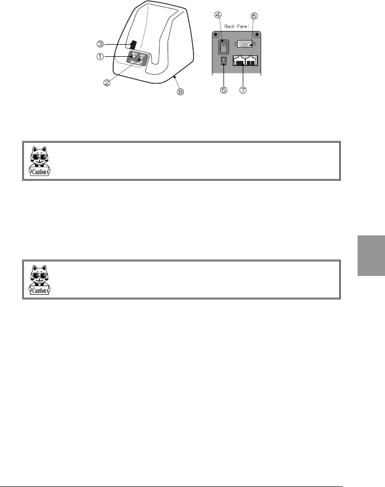
6-1 Introduction
6-3
Chap.
6
6-1-1 Part Names
1. Power LED
Turns green when the power is ON.
The light turns red during communication or communication standby.
Start transmission and reception of a file when the power LED is green. (Refer to "
■About the power LED" (P.6-4))
2. Communication LED
Turns orange during data transmission from the CTR-800-11W.
Turns green during data reception to the CTR-800-11W.
3. Infrared communication (IrDA) interface
Performs infrared communication (IrDA) with the CTR-800-11W.
(IrDA SIR 1.2 Low Power Option standard)
If the infrared communication (IrDA) interface is dirty, it may cause incorrect
operation.
4. Power switch
5. AC power connector
6. RS-232C connector
Used to connect the communication cradle to the host computer via a HIF-51
PC connection cable (WRS-AXC003A: option).
7. RS-485 Connector × 2
Used to create a daisy chain connection by connecting an communication
cradle to other communication cradles (HIF-51) via a daisy chain connection
cable (STP-C001A: optional).

Chapter 6 Communication Cradle (HIF-51)
6-4
Chap.
6
8. DIP switches
Sets up the communication cradle (HIF-51).
(Factory settings = DIP switches 1 to 6 are all turned off.)
Do not change the factory settings of DIP switches No.2 to No.6 at the bottom of
the communication cradle (HIF-51).
If the DIP switches are changed, the unit may operate incorrectly or fail when
creating a daisy chain connection with two or more units. For details about con-
necting more than one unit via a daisy chain connection, refer to P. 6-6
■About the power LED
If the CTR-800-11W is removed from the communication cradle (HIF-51) during
communication, the power LED may remain red for a while. At this point, the
communication process is still progressing between the communication cradle
(HIF-51) and the host computer. After the communication process has
completed and the power LED turns green, start the transmission and reception
of the next file.
When the power LED is red, the next file cannot be correctly transmitted or
received.
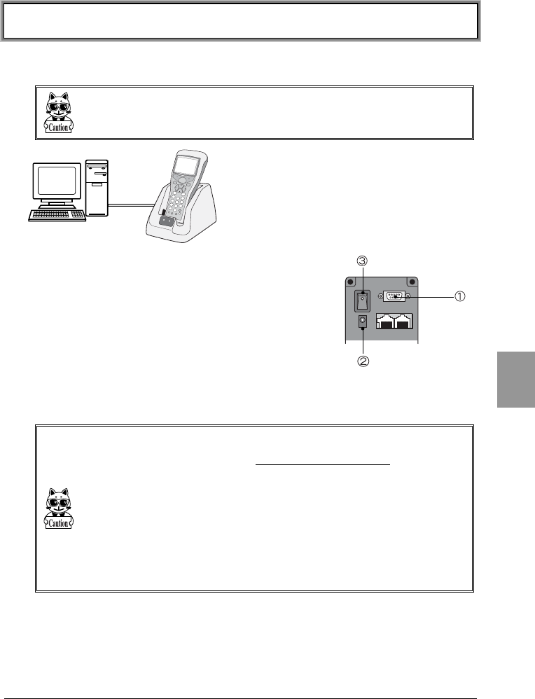
6-2 Connection
6-5
Chap.
6
6-2 Connection
6-2-1 Connection with a Host Computer
When connecting to a host computer, make certain you have the HIF-51 PC con-
nection cable (WRS-AXC003A) on hand.
1. Connect an communication cradle to a host
computer using the HIF-51 PC connection cable
(WRS-AXC003A).
2. Connect the AC adapter.
3. Turn ON the power switch on the back of the
communication cradle.
Once the CTR-800-11W has been prepared for data
transmission and reception, you can place the CTR-800-11W onto the unit
(HIF-51) and begin transmitting and receiving data. (P.4-32、4-34)
Please place the CTR-800-11W prepared for transmission and reception of data on
the communication cradle (HIF-51) when the power LED is green. If you place the
terminal onto the communication cradle (HIF-51) while the power LED is red,
transmission and reception will fail.
Please do not operate the CTR-800-11W while on the communication cradle (HIF-
51). The communication cradle may triple over or the CTR-800-11W may fall
from the unit, possibly causing a failure.
Please do not use the communication cradle near noise-emitting equipment, such
as a computer, fluorescent light etc.
Noise may cause incorrect communication.
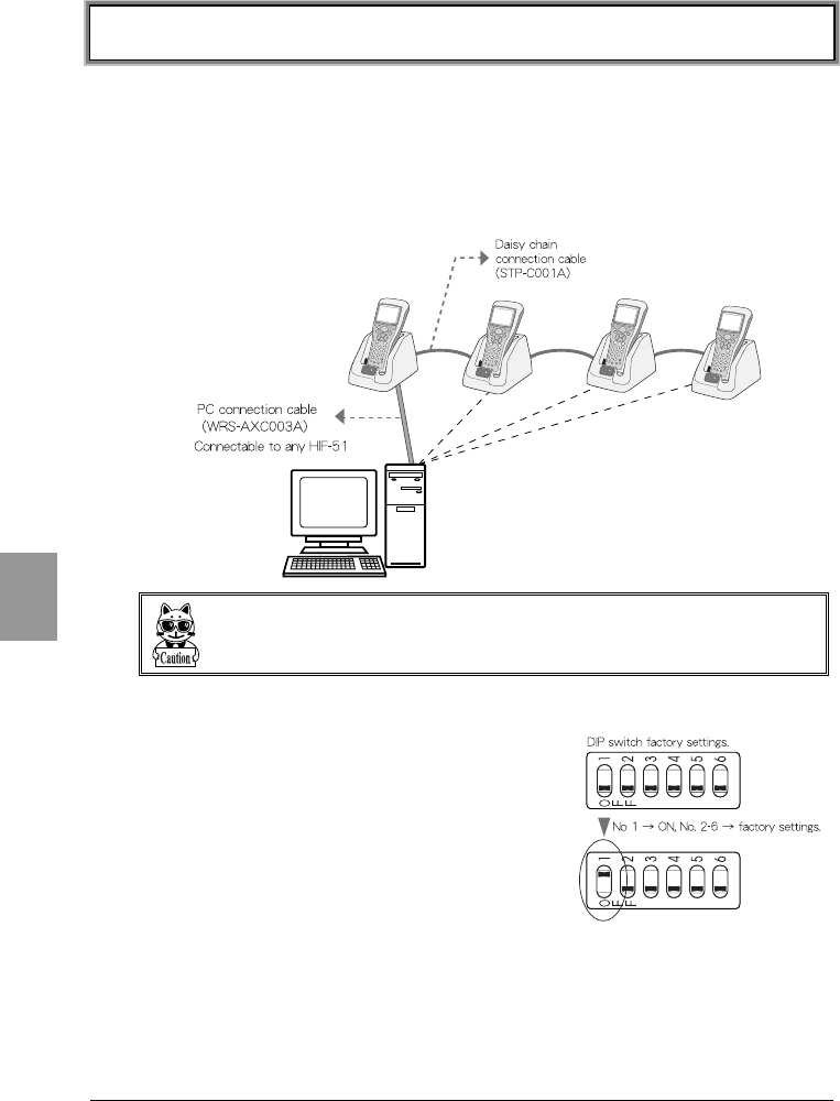
Chapter 6 Communication Cradle (HIF-51)
6-6
Chap.
6
6-3 Daisy Chain Connection
By using communication cradles (HIF-51) and daisy chain connection cables
(STP-C001A), you can create a daisy chain connection of a maximum of 16 units.
In a daisy chain connection, you can transmit one file to two or more terminals at
once from a host computer (broadcast transmission). Moreover, in the case
where two or more communication cradles are connected via a daisy chain
connection, it is possible to transmit data to a host computer from any unit.
During data communication via the communication cradle, do not turn ON or OFF
any of the other communication cradles.
If you do this, data communications may fail.
●DIP switch setup
When using a daisy chain connection, the "DIP
switches" on the bottom of the communication
cradle (HIF-51) needs to be set up.
The first switch of the "DIP switches" must be set
to "ON" for the communication cradles at both
ends of the daisy chain. Please do not change DIP
switches 2 to 6.
Refer to "6-3-1 Configuration Examples - (DIP
switch setup) " (P.6-7) for details of the "DIP
switch" settings.
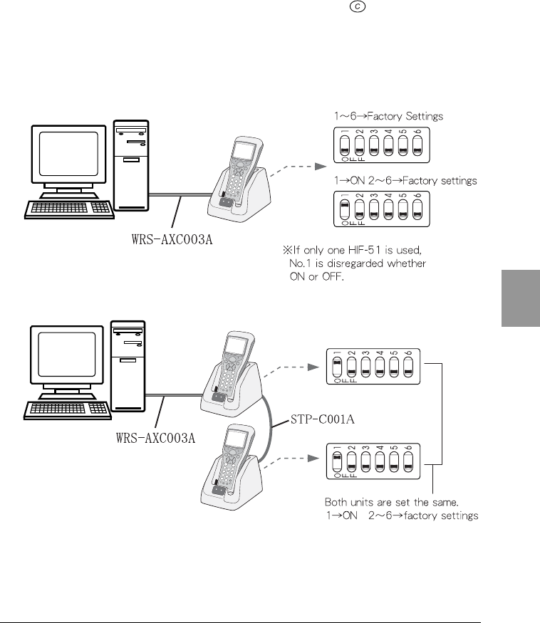
6-3 Daisy Chain Connection
6-7
Chap.
6
●Points to be noted during communication
If an communication cradle attempts communication with the host computer
while one of such units is already communicating via a daisy chain connection,
the message "Busy" is displayed on the CTR-800-11W screen, then the CTR-
800-11W and the unit will go into communication standby mode. Communication
will begin once the line becomes available. Press the key to cancel the
communication standby mode.
6-3-1 Configuration Examples - (DIP switch setup)
■When using one communication cradle (HIF-51).
■When using two communication cradles (HIF-51)
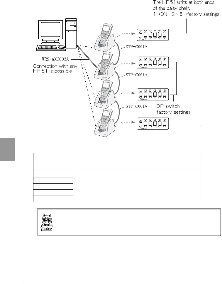
Chapter 6 Communication Cradle (HIF-51)
6-8
Chap.
6
■When using three or more communication cradles (HIF-51)
■DIP Switch Specification
Switch Number Description
1ON: terminating resistance;
OFF: no terminating resistance
2
3
4
5
6
Do not change these switches.
If the DIP switches on the bottom of the communication cradle (HIF-51) are
changed unnecessarily, the unit may not operate correctly and it may cause failure.
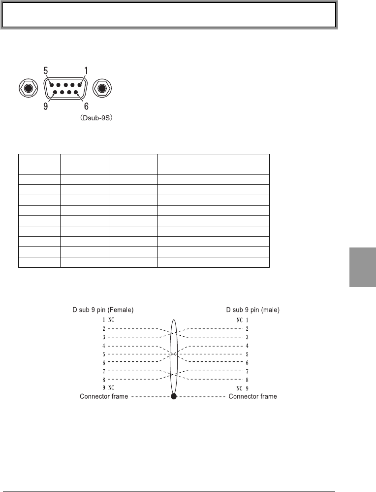
6-4 Interface
6-9
Chap.
6
6-4 Interface
6-4-1 RS-232C Interface
The terminal signal level is JISX5101 equivalent. The pin arrangement is of DTE
specification.
Pin
number
Terminal
name
Direction Description
1 NC - Prohibited
2 RxD Input Receive data
3 TxD Output Transmit data
4 DTR Output Data terminal ready
5 GND - Signal ground
6 DSR Input Data set ready
7 RTS Output Send request
8 CTS Input Transmission possible
9 NC - Prohibited
●Communication cradle (HIF-51) PC connection cable (WRS-AXC003A)
schematic
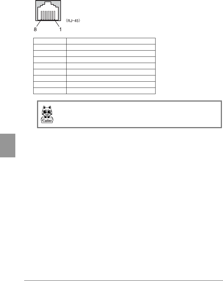
Chapter 6 Communication Cradle (HIF-51)
6-10
Chap.
6
6-4-2 RS-485 Interface
Pin number Description
1Prohibited
2Prohibited
3Prohibited
4Signal line (+)
5Signal line (-)
6HIF-51 connection detection line
7HIF-51 connection detection line
8GND
When using a daisy chain connection, be sure to use the daisy chain connection
cable (STP-C001A). The unit may fail if other purchased Ethernet cables are used.
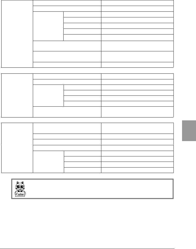
6-4 Interface
6-11
Chap.
6
6-4-3 Interface Specification
Communication system Full duplex
Synchronous system Start-stop synchronization
Baud rate 2400-115200bps
Data bit length 7 bits / 8 bits
Parity Even, odd, none
Stop bit length 1 bit / 2 bits
Communication
conditions
Flow control RTS/CTS control
Connector HDEB-9S Made by Hirose Electric
D-sub9S
Grommet RDG-LNA-W1 Made by Hirose
Electric
RS-232C
Female screw M2.6
Communication system Half duplex
Synchronous system Start-stop synchronization
Baud rate 2400-115200bps
Data bit length 7 bits / 8 bits
Parity Even, odd, none
Communication
conditions
Stop bit length 1 bit / 2 bits
RS-485
multi-drop
Connector HEC0470-01-230 Made by
Hoshiden - RJ-45
IrDA Standard IrDA SIR 1.2 Low Power Option
standard
Communication system Half Duplex
Transmission speed 2400-115200bps
Synchronous system Asynchronous method
Baud rate 2400-115200bps
Data bit length 7 bits / 8 bits
Parity Even, odd, none
Infrared
communications
(IrDA)
Communication
conditions
Stop bit length 1 bit / 2 bits
Communication conditions depend on the CTR-800-11W settings.

Appendix A
7 System Menu Factory Settings

Appendix A System Menu Factory Settings
Appendix A-2
App.
A
System Menu Factory Settings
Item Menu Tree Possible Setting Range Factory Settings
Startup 1:System→1:Startup System Menu
User Program
1:System Menu
COM
Speed
1:System→1:COM
→1:Speed
2400・9600・19200・
38400・57600・
115200bps
6:115200bps
COM
Data Bits
1:System→1:COM
→2:Data Bits
7 bits
8 bits
2:8 bits
COM
Stop Bits
1:System→1:COM
→3:Stop Bits
1 bit
2 bits
1:1 bit
COM
Parity
1:System→1:COM
→4:Parity
Odd Parity
Even Parity
No Pariyt
3:No Parity
COM Port 1:System→1:COM
→5:Port
IrDA
RS232C
1:IrDA
LCD 1:System→4:LCD Level 1 - 8 Level 4
BuzzerVolume 1:System→5:Buzzer
→1:Buzzer Volume
Level 1 - 8 Level 8
Buzzer Device Type 1:System→5:Buzzer
→2:Device Type
Buzzer
Vibrator
Both
1:Buzzer
Scanner
Trigger Mode
1:System→6:Scanner
→1:Trigger Mode
Normal Mode
Dupulex Mode
Release Mode
1:Normal Mode
Scanner
Power Mode
1:System→6:Scanner
→2:Power Mode
Coutiunuous On
Middle Power
Low Power
2:Middle Power
Suspend 1:System→7:Suspend ON
OFF
OFF
SSID 2:Network→1:RF
→1:Basic
→1:SSID
32 characters
consisting of single-
byte alphanumeric
character and symbol
80011
Roaming 2:Network→1:RF
→1:Basic
→2:Roaming
Fast
Normal
Slow
2:Normal
DOZE Timeouot 2:Network→1:RF
→1:Basic
→3:DOZE Timeout
Instantly, 1, 2, 3, 4,
5, 10 seconds, None
2:5 seconds
TxSpeed 2:Network→1:RF
→1:Basic
→4:TxSpeed
Auto, 1Mbps, 2Mbps,
1 or 2Mbps, 5.5Mbps,
11Mbps
1:Auto

Appendix A System Menu Factory Settings
Appendix A -3
App.
A
Item Menu Tree Possible Setting Range Factory Settings
WEP 2:Network→1:RF
→2:Security
→1:WEP
→1:WEP
Disable, 40bits,
128bits
Disable
WEP TxKEY_ID 2:Network→1:RF
→2:Security
→1:WEP
→2:WEP TxKEY_ID
KEY1, KEY2, KEY3,
KEY4
1:KEY1
Key Data 2:Network→1:RF
→2:Security
→1:WEP
→3:KEY Data
Setting the contents
of each WEP key (1,
2, 3, 4).
Characters which can
be used are "0" - "9",
"A" - "F" and "a" - "f."
When a 40 bits is
selected, the WEP is a
fixed 10 characters.
When 128 bits is
selected, it is a fixed
26 characters
AuthenMode 2:Network→1:RF
→2:Security
→2:Authen Mode
OPEN, SHARED OPEN
Preamble 2:Network→1:RF
→3:Advanced
→1:Preamble
LONG, SHORT LONG
RTS_Threshold 2:Network→1:RF
→3:Advanced
→2:RTS_Threshold
Even value of
between 0-3000
bytes
2432 (byte)
IP Address 2:Network→2:TCP/IP
→1:IP Address
value which is divided
into four fields by a
period
000.000.000.000
Subnet Mask 2:Network→2:TCP/IP
→2:Subnet Mask
value which is divided
into four fields by a
period
000.000.000.000
Gateway 2:Network→2:TCP/IP
→3:Gateway
value which is divided
into four fields by a
period
000.000.000.000
DHCP Client 2:Network→3:DHCP Not use
Run now
Run at startup
1:Not use
FTPHost Address 2:Network→4:FTP
→1:Host Address
value which is divided
into four fields by a
period
000.000.000.000
FTP Username 2:Network→4:FTP
→2:Username
up to 18
alphanumeric
characters
No settings
FTP Password 2:Network→4:FTP
→3:Password
up to 20
alphanumeric
characters
No settings

Appendix A System Menu Factory Settings
Appendix A-4
App.
A
Item Menu Tree Possible Setting Range Factory Settings
Primary DNS Server 2:Network→5:DNS
→1:Primary Server
value which is divided
into four fields by a
period
000.000.000.000
Secondary DNS
Server
2:Network→5:DNS
→2:Secondary Server
value which is divided
into four fields by a
period
000.000.000.000
SNMP Community
(R/Only)
Community Name
2:Network→6:SNMP
→1:Community(R/Only)
→1:Community Name
public
SNMP Community
(R/Only)
Manager IP Address
2:Network→6:SNMP
→1:Community (R/Only)
→2:Manager Address
000.000.000.000
SNMP Community
(R/W)
Community Name
2:Network→6:SNMP
→2:Community (R/W)
→1:Community Name
private
SNMP Community
(R/W)
Manager IP Address
2:Network→6:SNMP
→2:Community(R/W)
→2:Manager Address
000.000.000.000
SNMP Trap
Community Name
2:Network→6:SNMP
→3:Trap
→2:Community Name
CTR800
SNMP Trap
Manager Address
2:Network→6:SNMP
→3:Trap
→2:Manager Address
000.000.000.000
SNMP Trap
Authentication
2:Network→6:SNMP
→3:Trap
→3:Authentication
1:Enable
2:Disable
2:Disable
ping Host Address 6:Test→1:RF
→1:Parameter
→1:Host Address
value which is divided
into four fields by a
period
000.000.000.000
ping packet size 6:Test→1:RF
→1:Parameter
→2:Packet size
32・64・128・256・
512・1024・1500 byte
1:32 byte
ping
Timeout
6:Test→1:RF
→1:Parameter
→3:Timeout
1~255 seconds 1 second
ping Count 6:Test→1:RF
→1:Parameter
→4:Count
0~255 times 4 times

Appendix B
8 Sample Barcode
Appendix B Sample Barcode
Appendix B-2
App.
B
Sample Barcode
■JAN13
4 994121 104579 4 994121 102070
■JAN8
4912 3456 4911 2238
■UPC-E
0001234 4 0 999999 2

Appendix B Sample Barcode
Appendix B-3
App.
B
■CODE39 (C/D)
*12345F* *ABCDEH*
■CODE39 (No C/D)
*123456* *ABCDEF*

Appendix B Sample Barcode
Appendix B-4
App.
B
■NW-7 (C/D)
a123456$a b-$/456/0b
■NW-7 (No C/D)
c567890c d:/+789d
■NW-7 (HEX)
a A B C D E F a b D E F A B C b

Appendix B Sample Barcode
Appendix B-5
App.
B
■ITF (C/D)
1234567895 9876543215
■ITF (No C/D)
1234567890 9876543210

Appendix B Sample Barcode
Appendix B-6
App.
B
■ITF (Standard ITF-14)
04912345678904 11223344556675
■ITF (Extended ITF-16)
0104903333049409 1122334455667784
■ITF (Add on version ITF-6)
123457 112239

Appendix B Sample Barcode
Appendix B-7
App.
B
■CODE128 (Codeset A)
123456 ABCDEF
■CODE128 (Codeset B)
abcdef
!"#$%&'()
■CODE128 (Codeset C)
012345678901 112233445566778899

Appendix B Sample Barcode
Appendix B-8
App.
B
■EAN128 (Codeset A)
(01)14530825000013(17)001231
■EAN128 (Codeset B)
(06)17458663525300(143)543210
■EAN128 (Codeset C)
(10)13589645123004(48)468125

9 Index

Index
Index-2
A
access point......................... 1-5, 1-8
antenna .....................................2-4
antenna power output ..................2-4
application program .....................3-2
authen mode ..............................A-3
authentication .......... 4-19, 4-20, 4-27
automatically started program ......4-7
auto-power-off .......................... 4-50
B
backlight ............................. 2-3, 4-3
backspace key ............................1-3
backup battery................... 2-3, 2-12
barcode (sample) ........................B-2
barcode scanning test ................ 4-48
barcode sensor ...........................1-2
battery
charging time ........................ 2-12
estimated usable period .......... 2-12
precautions in use .................. 2-12
battery cover ..............................1-3
battery pack ............... 1-3, 2-9, 2-12
charging..................................2-9
cleaning of electrodes ............. 2-11
installing ............................... 2-10
prolonged storage .................. 2-11
removing............................... 2-10
replacing ............................... 2-11
worn out ............................... 2-11
battery pack lock lever.................1-3
battery voltage ......................... 4-41
baud rate ...................................4-8
browser............................... 1-6, 3-4
BS key .......................................1-3
buzzer........................ 2-3, 4-11, A-2
C
C Key.........................................1-3
cancellation Key ..........................1-3
charging.....................................2-9
charging the backup battery ....... 2-13
cleaning of electrodes ................ 2-11
clock (Status Menu)................... 4-42
clock function..............................2-3
clock setup .................................4-9
CODE128 (sample barcode) ....... B-7
CODE39 (sample barcode) ......... B-3
codes scanned............................ 2-3
communication cradle ...........1-5, 6-2
communication system................ 2-4
communication via IrDA .............. 1-5
community ...............................4-25
community name.............. 4-25, 4-26
connecting to a host computer ..... 1-5
continuous on ...........................4-14
continuous operation time ........... 2-3
contrast adjustment.................... 2-3
count ........................................ A-4
CTR-800 browser........................ 3-2
D
daisy chain ................................ 6-6
data bits ..............................4-8, A-2
data storage .............................. 3-3
dead zone.................................. 2-7
decode mode ............................4-13
dedicated charger ....................... 2-9
deleting files .............................4-36
device ....................................... A-2
DHCP client................................ A-3
DHCP client function ......... 1-10, 4-23
DHCP function ...........................4-23
DHCP request............................. 4-5
DHCP server .............................. 1-6
DHCP setup................................ 1-9
DHCP Setup ..............................4-23
dimensions ................................ 2-3
DIP switch ................................. 6-7
display area ............................... 2-3
display characters....................... 2-3
display LED ................................ 2-3
display size ................................ 2-3
DNS .........................................4-24
DNS setup ......................... 1-9, 4-24
domestic standards..................... 2-4
double-byte characters ...............2-16
DOZE timeout ...........................4-17
drip-proof .................................. 2-3
drive ........................................4-39
drive configuration...................... 3-3
drive information .......................4-39
drop impact proof ....................... 2-3

Index
Index-3
E
EAN128 (sample barcode) ............B-8
ENT Key .....................................1-2
enter key ...................................1-2
ESSID ...................................... 4-18
extended character.................... 2-16
extension ...................................3-3
external interface .......................... 2-3
F
F drive ....................... 2-14, 3-3, 4-4
file information.......................... 4-38
file name ....................................3-3
file name used by the CTR-800-11W
..............................................3-3
file naming .................................3-3
font ......................................... 4-40
FROM.........................................2-3
FTP............................................A-3
FTP client function ..................... 4-24
FTP server ..................................1-6
FTP setup .......................... 1-9, 4-24
full initialization......................... 4-52
function keys ..............................1-2
G
gateway ............................ 4-22, A-3
H
hand strap..................................1-3
Handy5250.................................1-6
HBC-51 ......................................2-9
HIF-51 ................................ 1-5, 6-2
HOP-C031 ..................................1-5
host address ...................... 4-43, A-3
host computer.............................6-6
HQC-51/HQC-54 .........................2-9
I
illumination conditions .................2-3
inclination of a bar-code and the angle
with which it can be read ..........2-7
initialization .............................. 4-51
international standards ................2-4
IP address ......................... 4-22, A-3
IrDA communication ....................4-8
IrDA interface ............................ 1-3
irradiation angle ......................... 2-5
ITF (sample barcode) ......... B-5, B-6
J
JAN13 (sample barcode) ............ B-2
JAN8 (sample barcode).............. B-2
K
key input test............................4-49
KEY setup .................................4-19
L
large capacity battery.................. 2-2
laser irradiation time ..................4-13
LCD ....................................1-2, A-2
LCD display................................ 2-3
LED indicator ............................. 1-2
light source................................ 2-3
low battery ...............................4-50
low power.................................4-14
low voltage warning ...................4-50
M
MAC address .............................4-28
main battery .............................. 2-3
main features of the CTR-800-11W
............................................. 2-2
manager address.......................4-26
manager IP address ...................4-25
memory .................................... 2-3
memory backup period...............2-12
initialization of the .....................4-51
middle power ............................4-14
MRD.......................................... 2-3
N
non-volatile memory ................... 3-3
normal mode ............................4-13
number digits scanned ................ 2-3
number of channels .................... 2-4
number of trials.........................4-44
numeric keys ............................. 1-3
NW-7 (sample barcode)............. B-4

Index
Index-4
O
open authentication ................... 4-20
operating environment .................2-3
operation monitor........................1-6
OS version................................ 4-42
P
packet size ............................... 4-43
parity.................................. 4-8, A-2
password....................................A-3
PC connection cable .....................1-5
ping......................................... 4-45
ping command .......................... 4-44
ping host address ........................A-4
ping packet size ..........................A-4
ping test................................... 1-10
pitch ..........................................2-8
port ....................................4-8, A-2
power mode ...............................A-2
power save mode ...................... 4-14
power source ..............................2-3
power switch ..............................1-3
preamble........................... 4-21, A-3
primary DNS server .....................A-4
product specifications...................2-3
PW key ......................................1-3
R
receiving files via serial
communications ..................... 4-34
receiving files via wireless
communications ..................... 4-33
red light semiconductor laser ........2-3
release mode ............................ 4-13
resolution ...................................2-3
resolution depth ..........................2-5
RF ........................................... 4-43
RF test ..................................... 4-43
roaming .....................................A-2
roaming level ............................ 4-17
role of an access point .................1-8
roll ............................................2-8
RS-232C ....................................1-5
RS-232C interface ................ 1-3, 2-4
RTS threshold ........................... 4-21
RTS_Threshold ............................A-3
S
S drive ....................... 2-14, 3-3, 4-4
sample barcode .......................... A-2
scan key.................................... 1-2
scanning depth........................... 2-5
scanning distance range .............. 2-6
scanning range........................... 2-5
scanning specifications ................ 2-5
scanning width ........................... 2-3
screen contrast..........................4-10
screen display ............................ 4-4
screen display test .....................4-48
screen output characters ............2-16
searching for access points .........4-45
secondary DNS server ................. A-4
security ..................................... 2-4
security setup ............................ 1-9
selecting a device ......................4-12
serial communication setup.......... 4-8
serial communication test ...........4-47
serial number ............................. 1-3
SF key....................................... 1-3
shared key authentication...........4-20
shift key .................................... 1-3
single-byte characters ................2-17
skew ......................................... 2-7
SNMP ....................... 4-25, 4-27, A-4
speed........................................ A-2
SRAM ........................................ 2-3
SSID .................................4-18, A-2
SSID setup ........................ 1-9, 4-17
starting an application ................4-30
starting the System Menu ............ 4-5
startup ...................................... A-2
status.......................................4-41
stop bit ..................................... 4-8
stop bits .................................... A-2
storage humidity ........................ 2-3
storage temperature ................... 2-3
STP-C001A ................................ 6-6
subnet mask ...................... 4-22, A-3
suspend .................................... A-2
suspend function .............. 2-15, 4-15
suspended state ......................... 4-5
System Menu .. 3-2, 3-4, 4-2, 4-3, 4-6
system program ......................... 3-2

Index
Index-5
T
target address .......................... 4-26
TCP/IP .......................................2-2
TCP/IP communication .................1-8
TCP/IP communications.............. 4-22
TCP/IP setup...............................1-9
terminal ID ............................... 4-29
testing files............................... 4-37
the CTR-800-11W software...........3-2
timeout ...............................A-2, A-4
timeout period .......................... 4-44
transmission range ......................2-4
transmission speed ............. 2-4, 4-17
transmitting files (via serial
communications).................... 4-32
transmitting files (via wireless
communications).................... 4-31
trap setup ................................ 4-26
trigger mode...............................A-2
Tx Speed....................................A-2
TxKEY_ID ................................. 4-19
U
uesername .................................A-3
UPC-E (sample barcode).............B-2
V
vibrator............................. 2-3, 4-11
volatile memory ..........................3-3
volume of buzzer....................... 4-11
W
warning LED ........................ 1-2, 2-4
WebGlider .................... 1-6, 3-2, 3-4
weight .......................................2-3
Welfer II for Windows ......... 1-6, 1-10
WEP......................... 4-19, 4-20, A-3
WEP KEY Data.............................A-3
WEP TxKEY_ID ............................A-3
wireless communication system ....1-8
wireless communications ..............1-9
wireless communications setup ... 4-16
detailed setup ........................ 4-21
wireless frequency.......................2-4
working humidity.........................2-3
working temperature ...................2-3
WRS-AXC003A ........................... 1-5