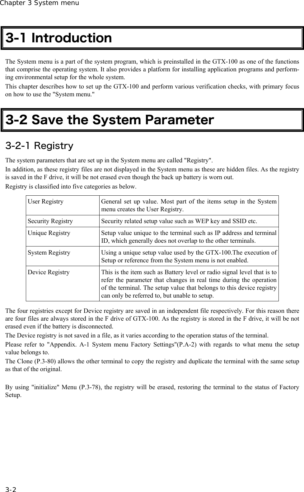
Welcat GTX100 Handy Terminal User Manual 7th M01GTX100
Welcat, Inc. Handy Terminal 7th M01GTX100
UserManual.wiki
>
Welcat
>
GTX100 User Manual
user manual
Navigation menu
Upload a User Manual
Namespaces
Wiki Guide
HTML
PDF
Info
Views
User Manual
Discussion / Help
Navigation


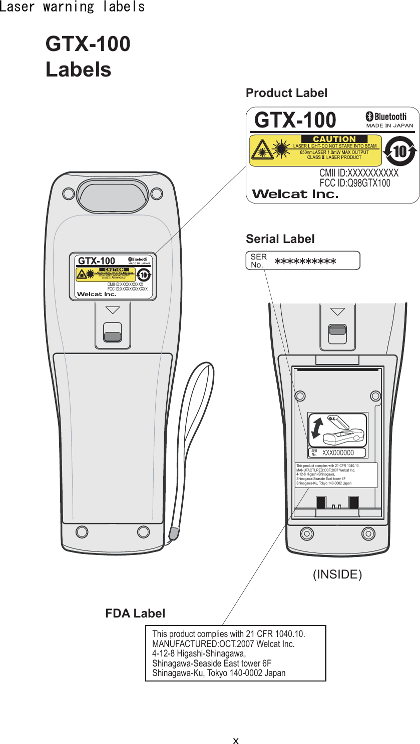
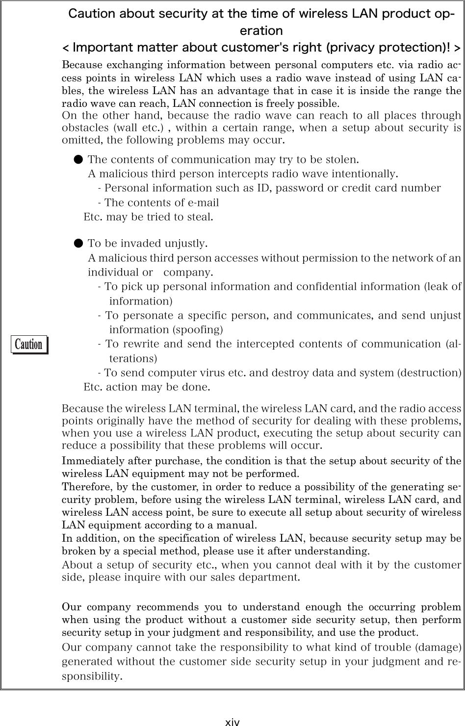
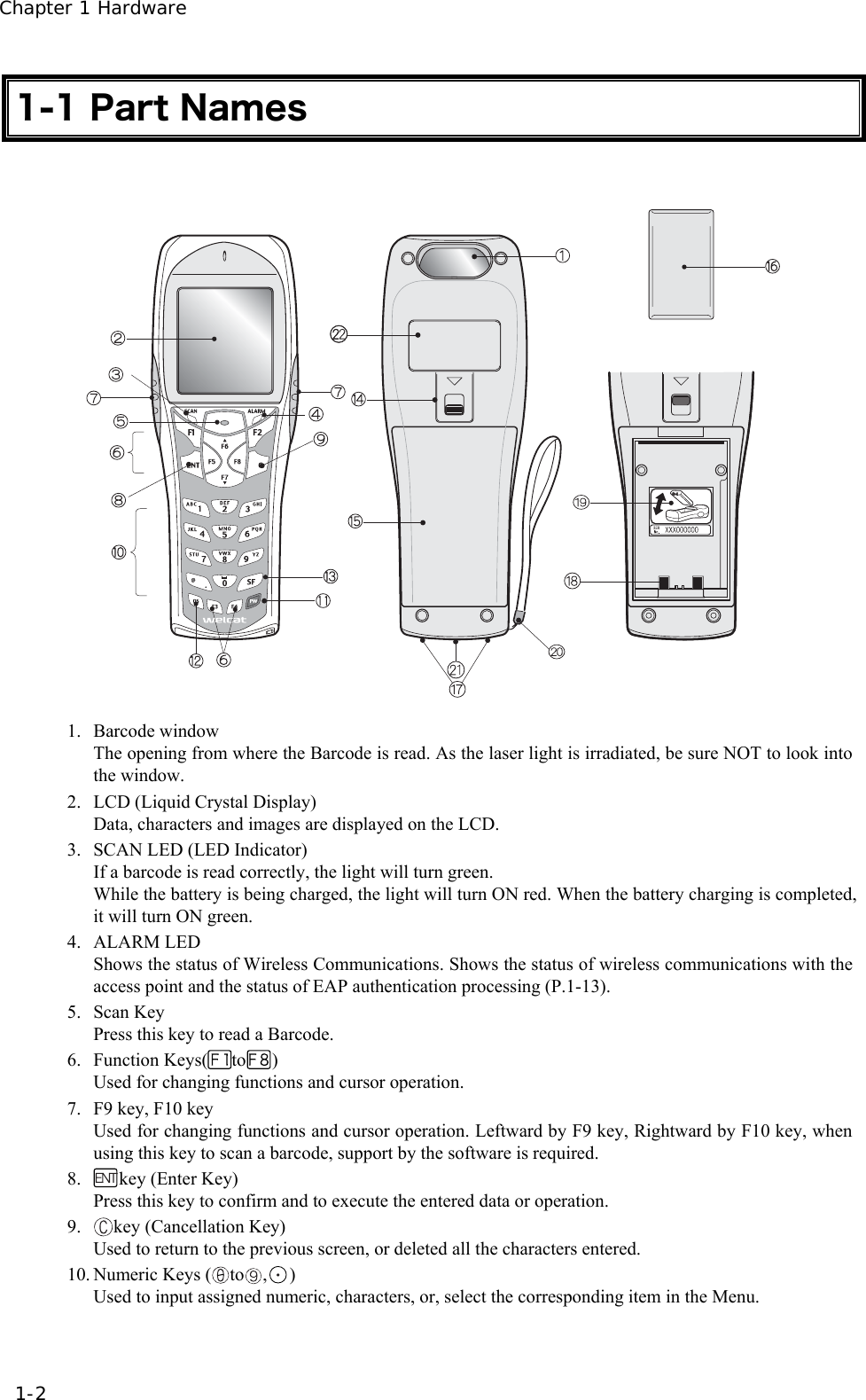
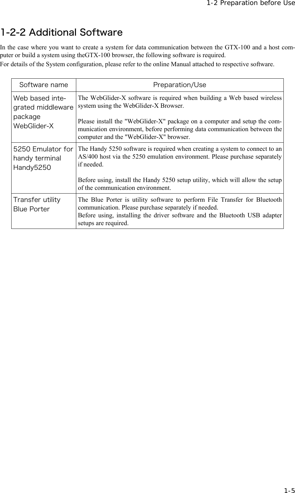
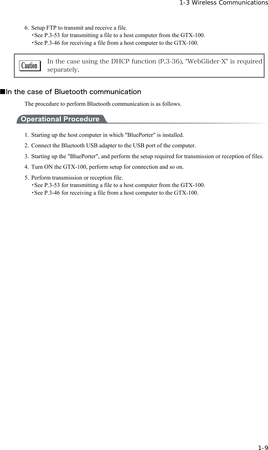
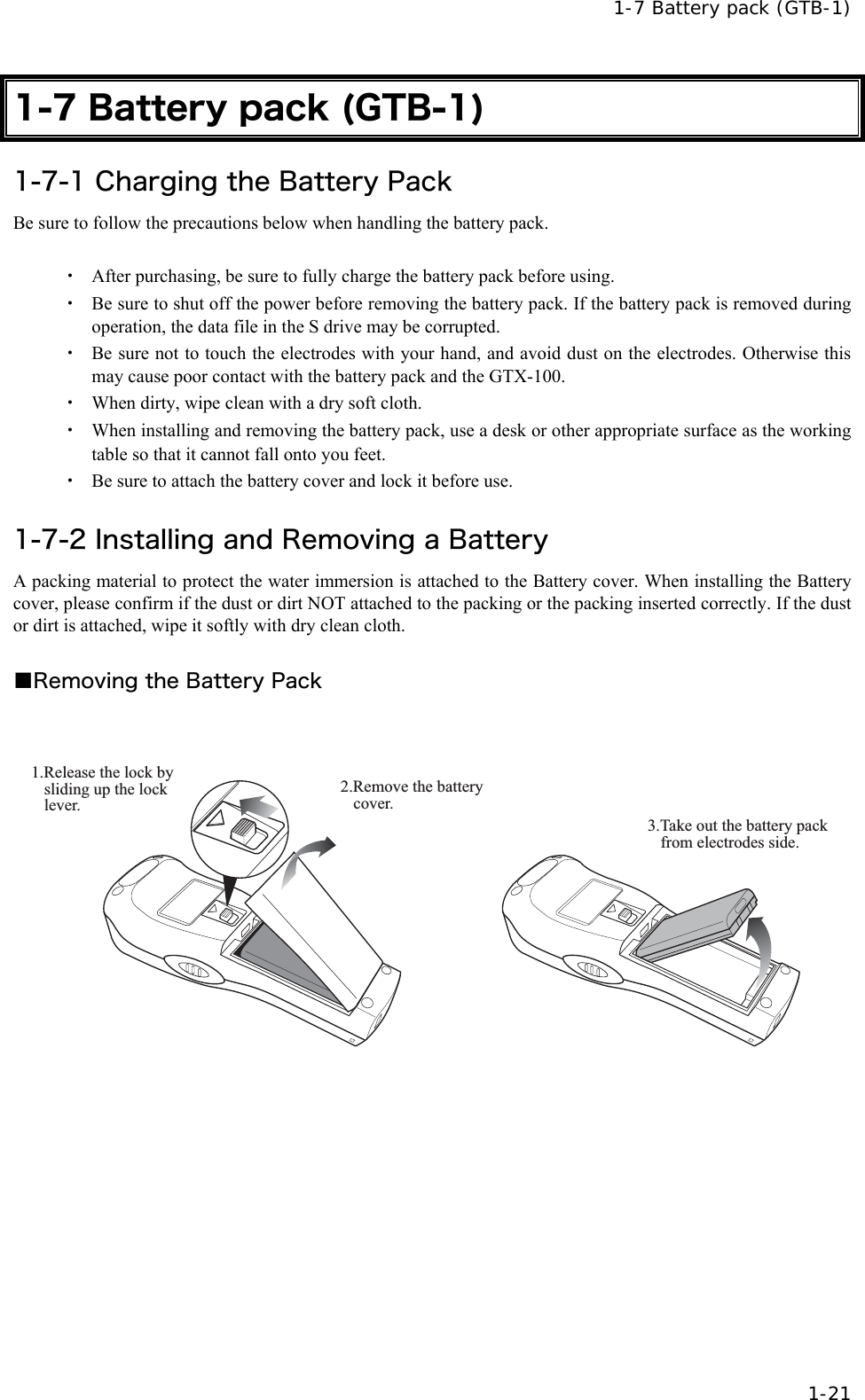
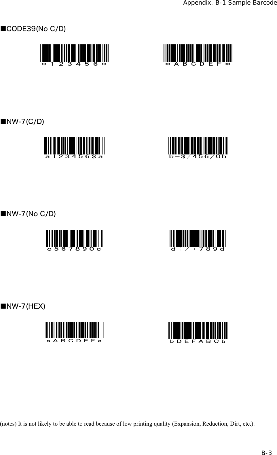
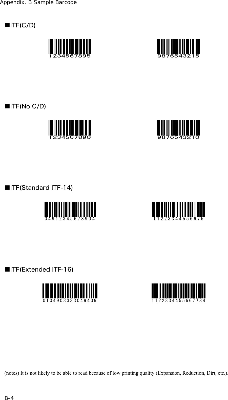
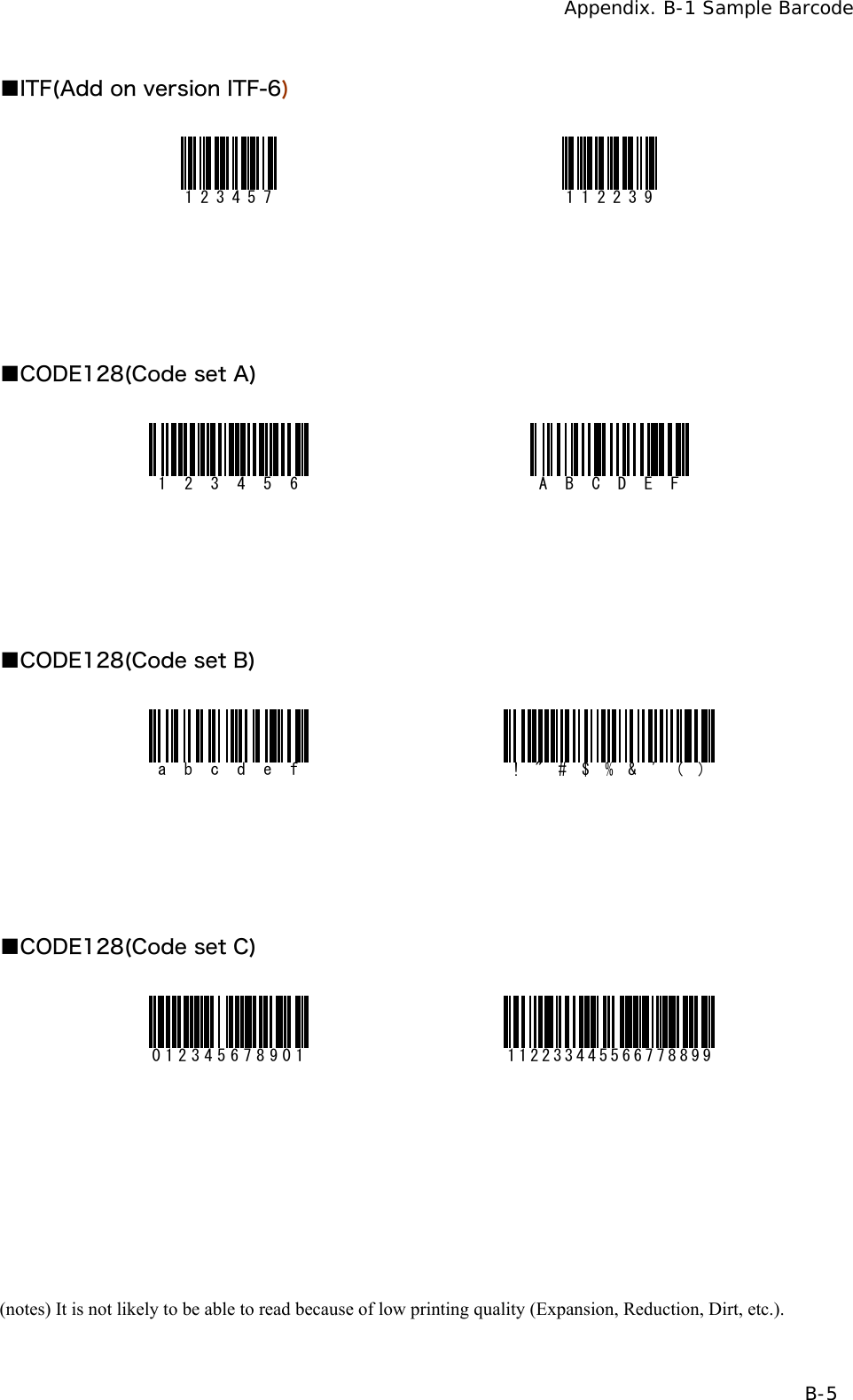
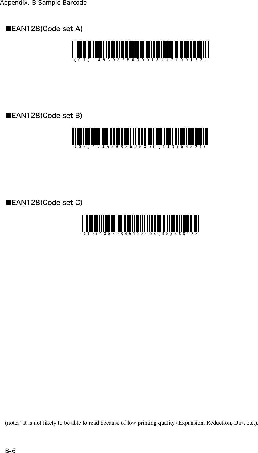
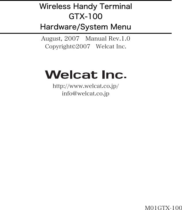
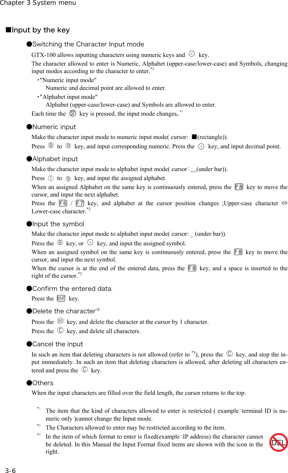
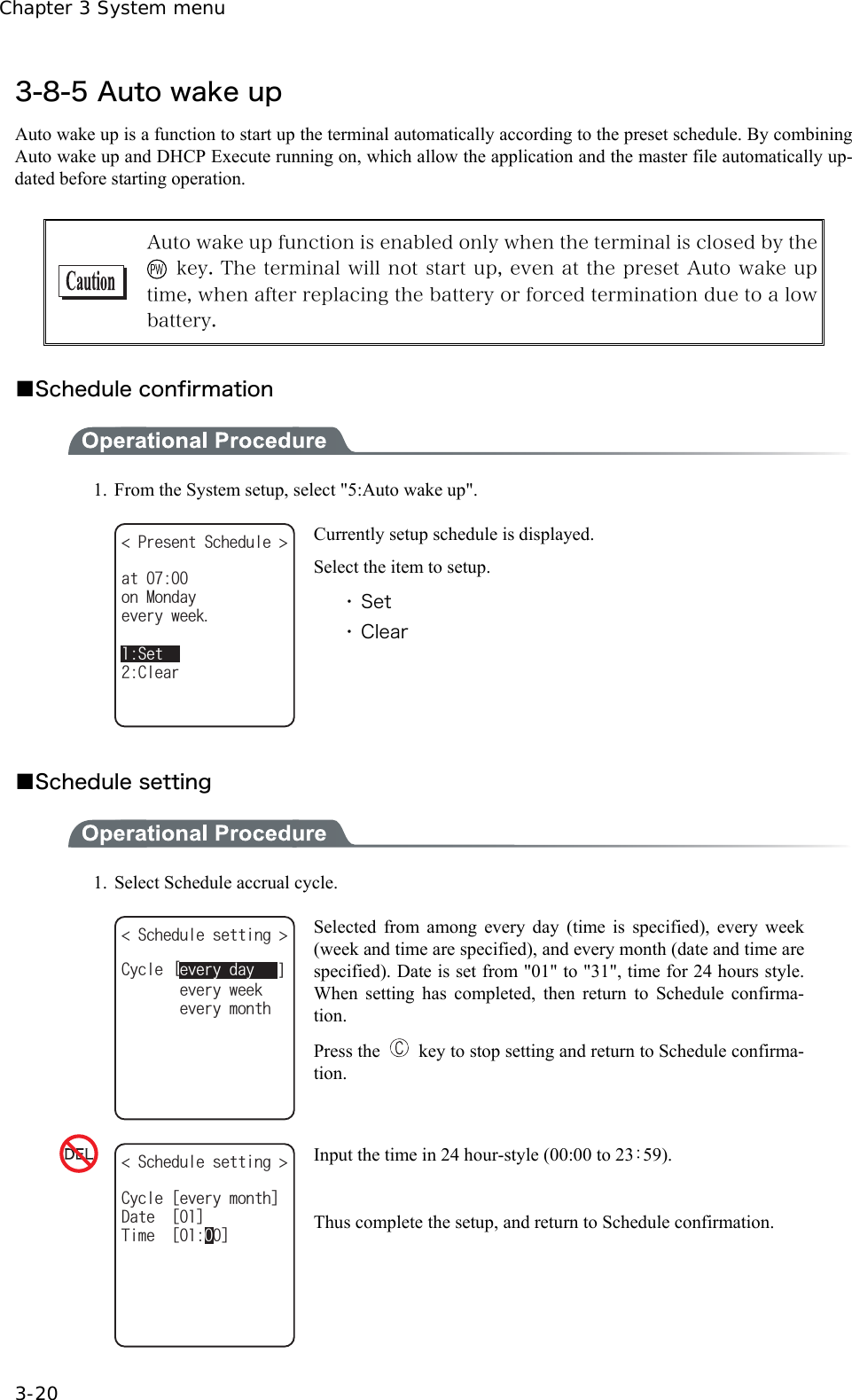
![3-4 System Menu Operations 3-5 3-4 System Menu Operations Here explains the Standard Operation Method of the System menu. ■Select the target item from the menu ●Selecting a Menu Item Selected item becomes highlighted (colors reversed= selected). Move the cursor either by pressing to key, which corresponds to the item, or, by using the di-rection ( to ) key. ●confirm the selected item Press the key, and, confirm the selected item. The behavior after confirmation differs according to the item. ・ Execute the corresponding function ・ Show the decision [Yes] or [No] (check box) ・ Next Menu is displayed. ・ Sub menu is displayed. ●Cancel Selecting Press the key, to return to the previous operation. ●Screen display When the items in the Menu are not housed in a screen, the scroll bar for vertical direction is dis-played on the right of the screen. In addition, when the item name exceeds 1 line, the tail of the item name is displayed being converted in "→ " (KNG( ǫ*#$#0'41$/2ǫ%12#0$/2ǫ+0&':*6/ǫ.10).10)(+.'0#/'ǫ/#-'6:6ǽ/GPWǽ5&TKXG( (ǫ:$/2ǫ9):$176 ■Input Barcode data ●Barcode Scanning Press the scan key and irradiates the laser to scan a barcode. The irradiation time of the laser and scanning behavior are set up with trigger mode. In addition, Bar-code test menu is not subject to trigger mode. ●Barcode scanning condition The Barcode that can be scanned in the data input mode is as follows. NW-7, CODE39, JAN13/8, UPC-A/E, Industrial 2of5, ITF, CODE93, CODE128, RSS-14, RSS Limited](https://usermanual.wiki/Welcat/GTX100/User-Guide-859113-Page-60.png)
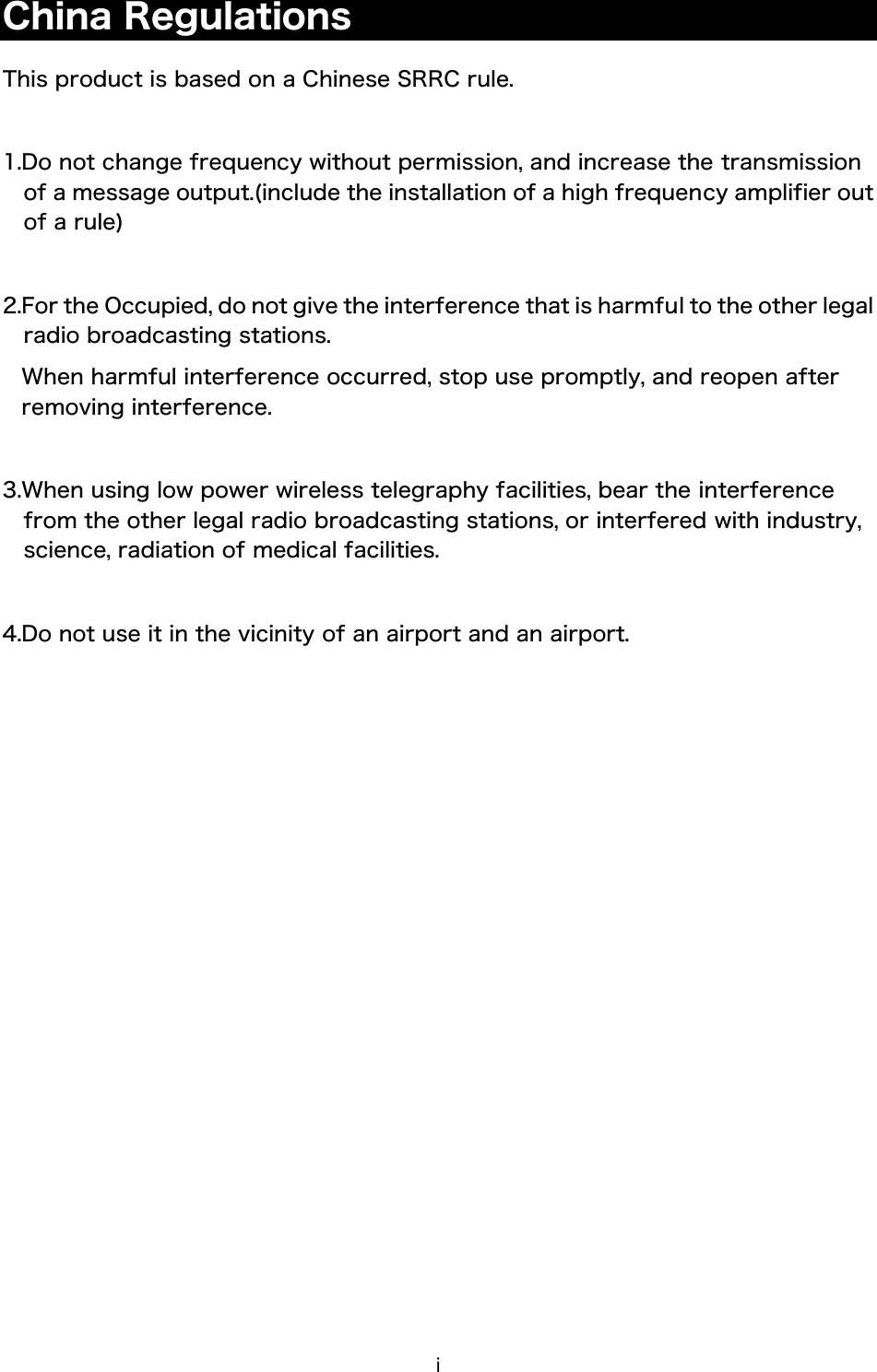
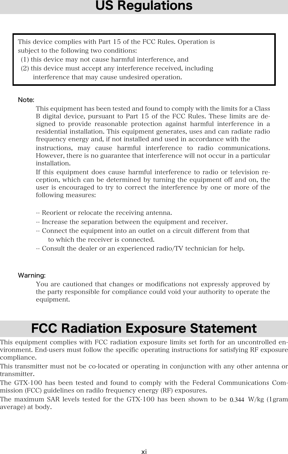
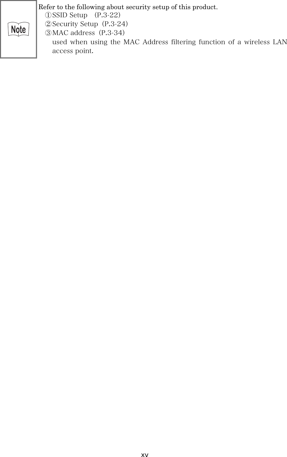
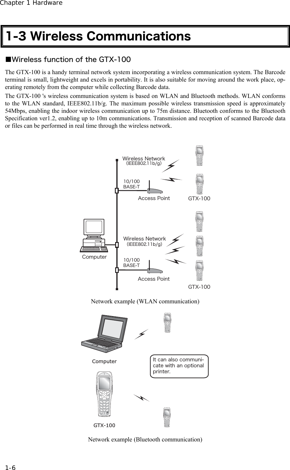
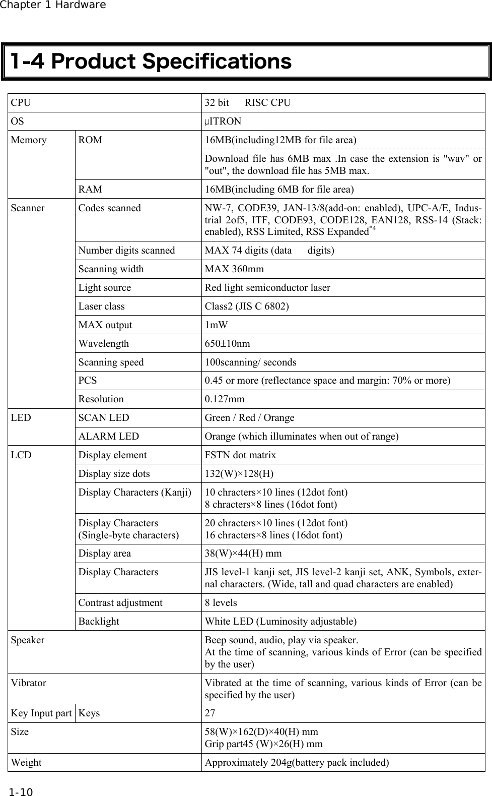
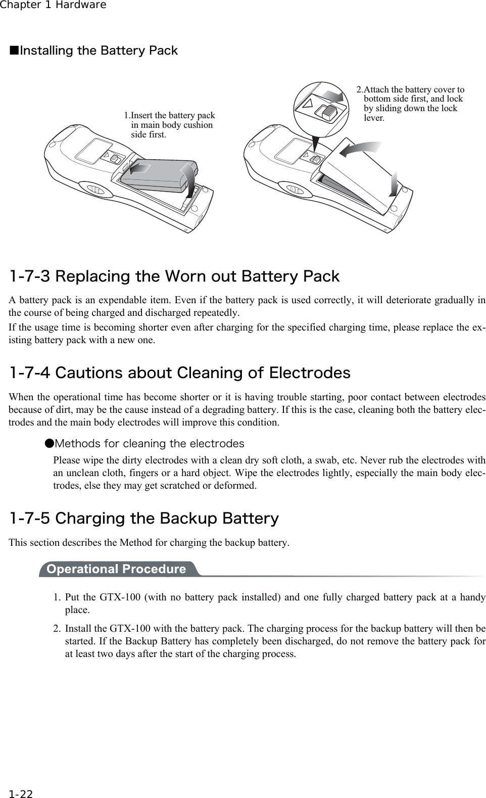
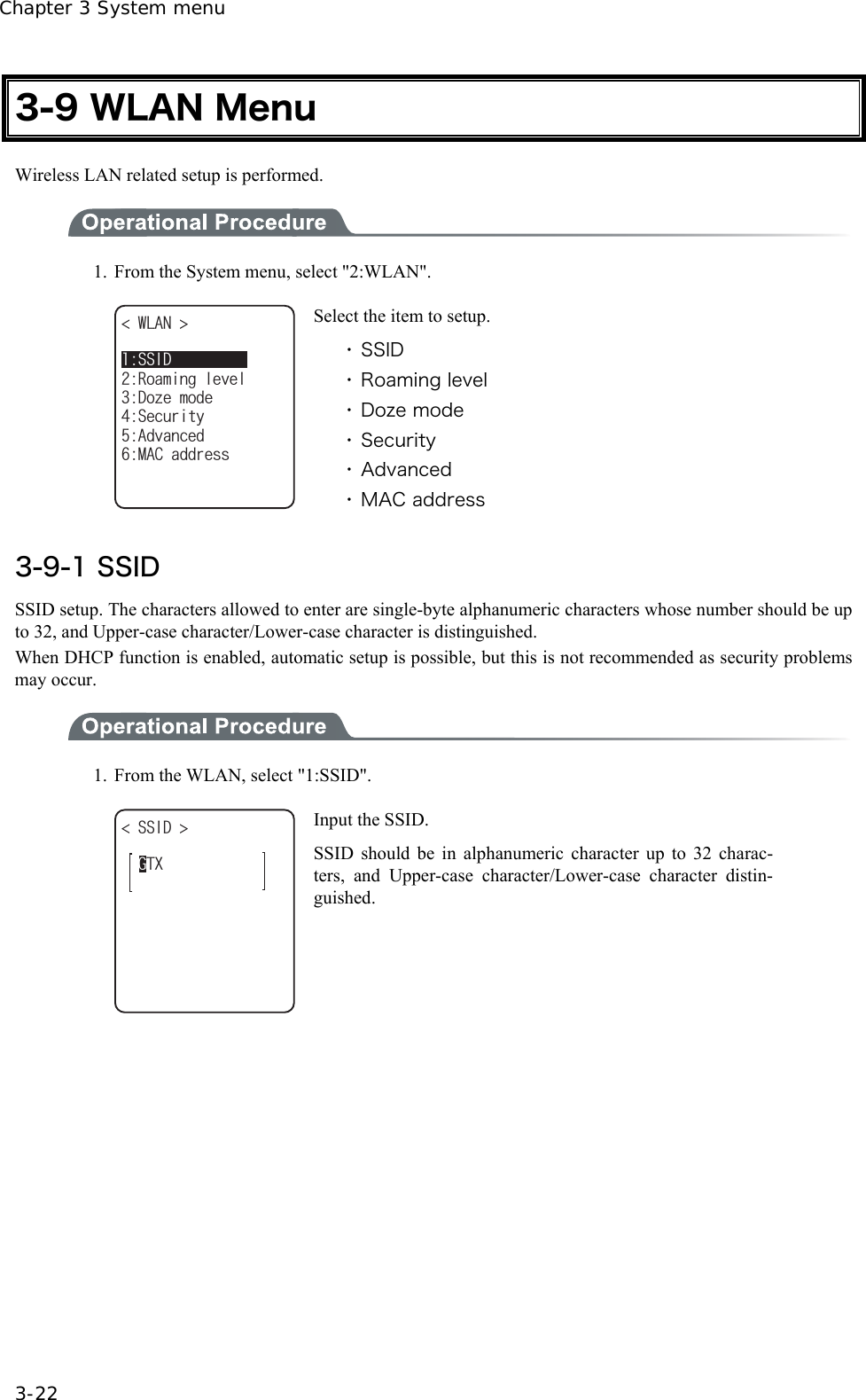
![3-4 System Menu Operations 3-7 ■Other operations ●Returning to the previous menu. Press the key. ●Check box operation By applying or removing checks in the square box, making the item selected/not selected. Each time the key is pressed, the status of Select /Not Select switches. Each time the key is pressed ,[Yes]/[No] switches. The check box is also applied when selecting many items at the same time. ●Radio buttun operation The item the inside of the small circle is dotted shows that it is currently enabled. Radio button is used to select one item from many items. ●Message box operation When two buttons are displayed in the lower part of the box; [Yes]/[No] etc., press or, key, or select the button by using the direction ( to ) key (Highlighted), and then press the key to confirm. Press the key to select the right button. In such a case with one button like "OK", press the key or key. ●Level meter operation. Setup value adjustment by stages. Move the slider Up and Down by / key. And then, press the key to confirm the level value. Press the key to cancel setup. ●Turning ON/ OFF the backlight. Each time by pressing the key, the backlight turns ON/ OFF. However in case the battery level is less than the regulated value, the backlight does not turn ON. ●Accessing to the Sub menu or function. When or is displayed in the lower part of the screen, press the corresponding key to display the Sub menu or execute the function. ●Modifying the indicator when operating The indicator (buzzer/audio/vibrator/LED) that works when operating allows itself to be modified to user's original setup. With regard to the modification Method, please refer to"■Indicator func-tion"(P.3-71). By modifying this setup users' are allowed to create their original indicator easily. In addition, there are some operations that the indicator is not applied.](https://usermanual.wiki/Welcat/GTX100/User-Guide-859113-Page-62.png)
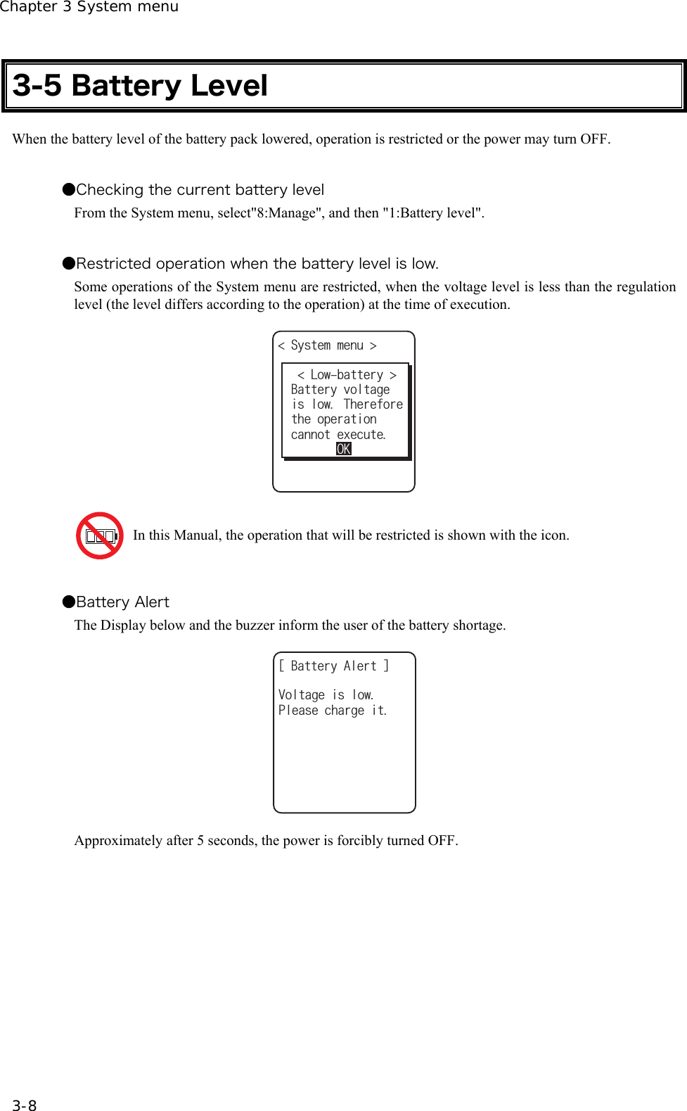
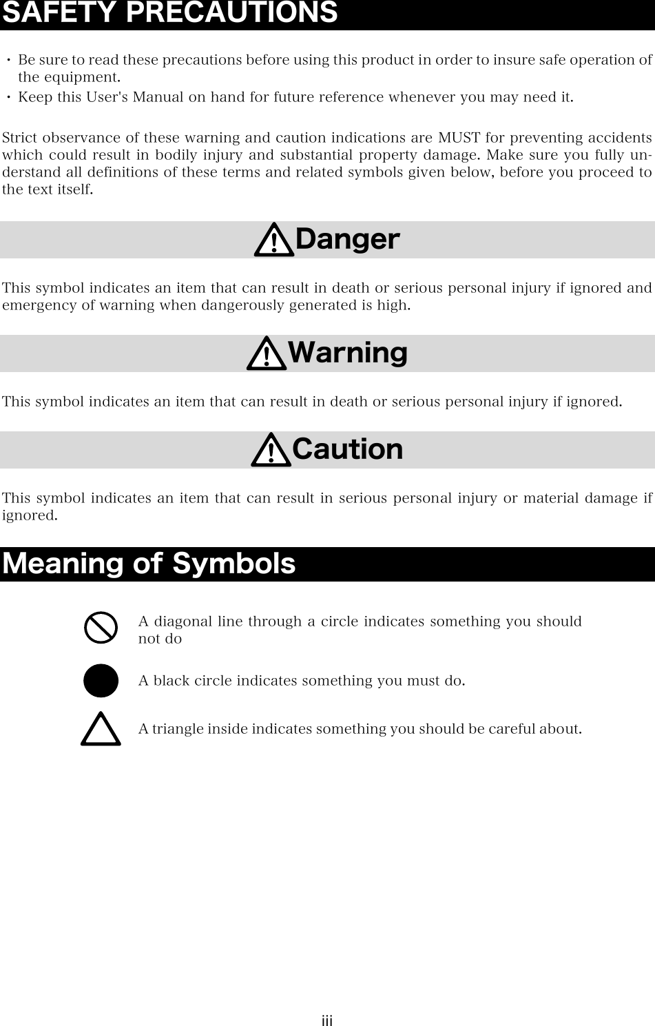
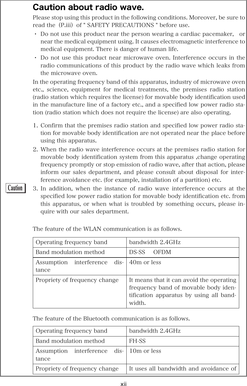
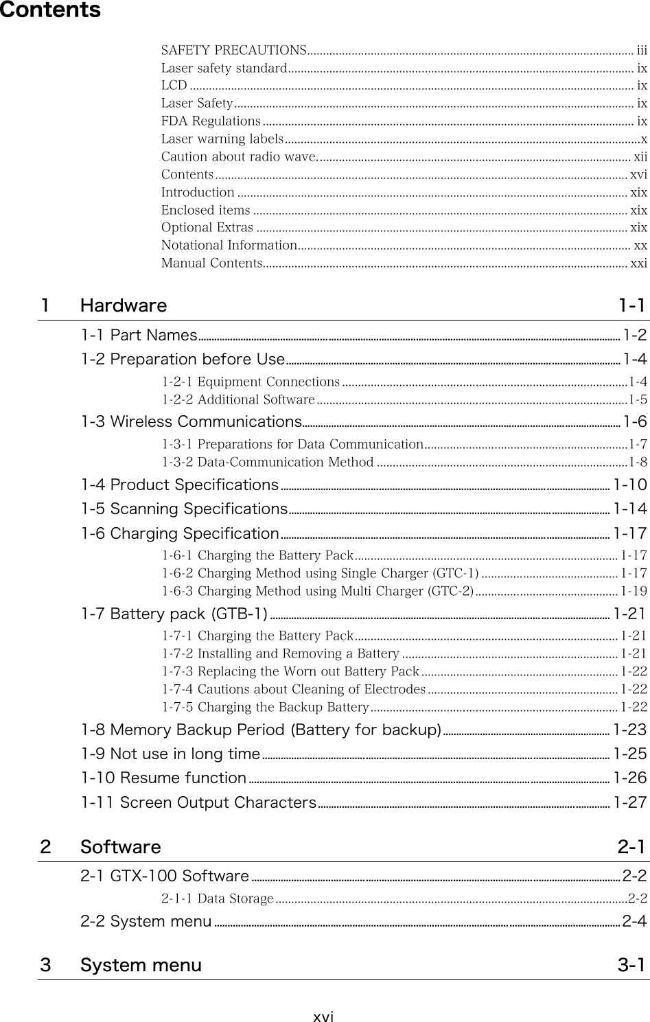
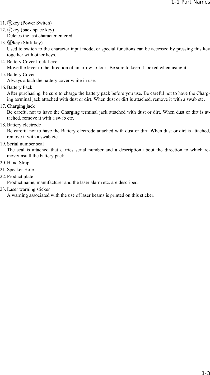
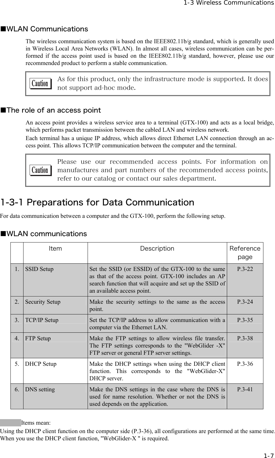
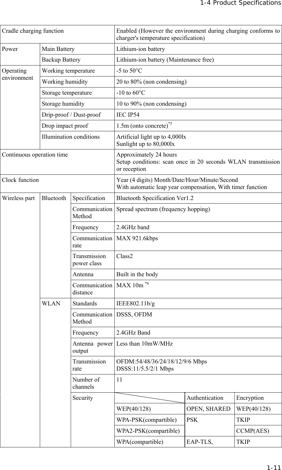
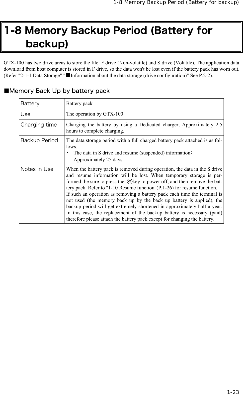
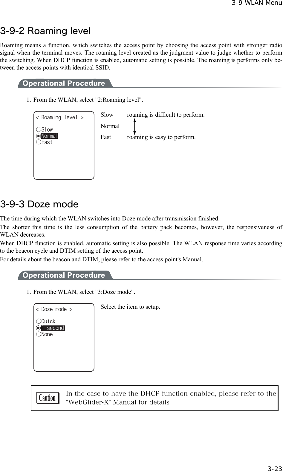
![3-6 Starting the System Menu 3-9 3-6 Starting the System Menu 3-6-1 How to Start the System menu 1. Once the GTX-100 has been correctly installed with a battery pack and if the current state is OFF, press the key for approximately 1 second. The power will turn ON and the System menu will be started. 2. The System menu is displayed immediately after the opening screen. 5[UVGOOGPW 0GVYQTM/CPCIG4GEGKXG6GUV5[UVGO+&9.#0&GXKEG(KNG If an application is set for " Auto execute" (P.3-15), hold down the scan key (excluding F9 and F10), and then press the key to start the System menu. 3-6-2 Executing a DHCP Request If the "■Startup type"(P3-37)is setup at[application boot], [System menu boot], the DHCP request will be executed every time of booting. If the system is in the state where wireless communications with an access point is possible and if the DHCP server and FTP server of the "WebGlider-X " Net-work Manager have been started, the various environmental setting values and specified files will be downloaded to the GTX-100 and automatic setup will be perform via the TCP/IP network. After the DHCP request has been executed, the applications set for "Auto exe-cute" if any, will start. (P.3-15) &*%2ENKGPV &*%2UGTXGT%QPPGEVVQ 3-6-3 Starting State for Wireless LAN Operation Immediately after starting, the GTX-100's wireless LAN communication unit is set to a resumed state. If the wireless communications related menu is selected immediately after starting, the GTX-100 will be ready for communication within 0.5 to 1 second.](https://usermanual.wiki/Welcat/GTX100/User-Guide-859113-Page-64.png)
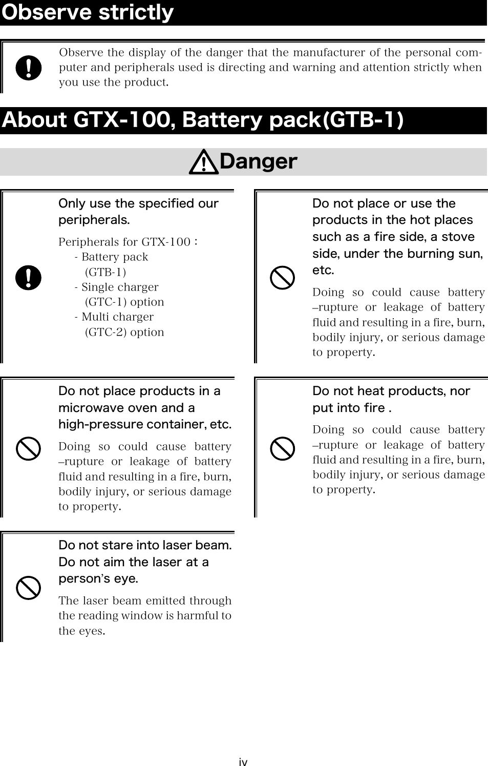
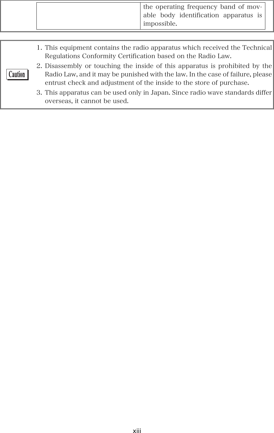
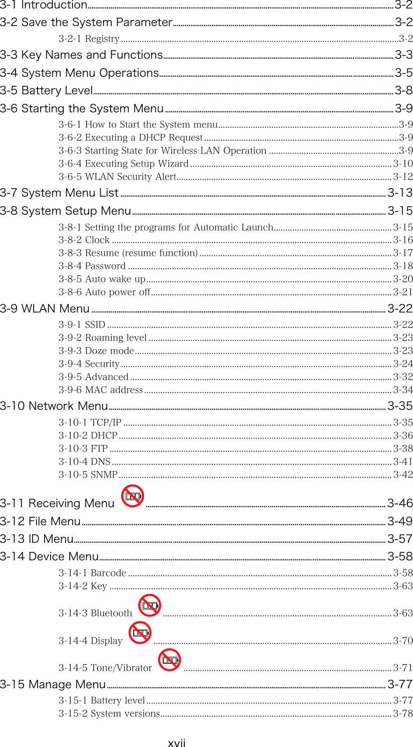
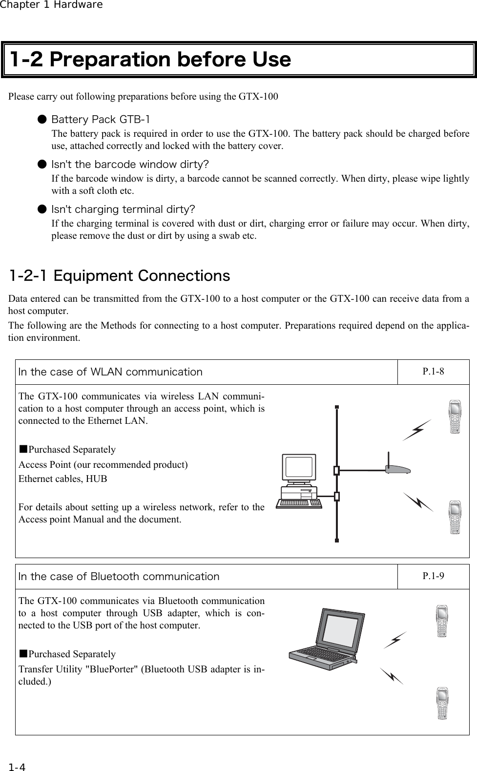
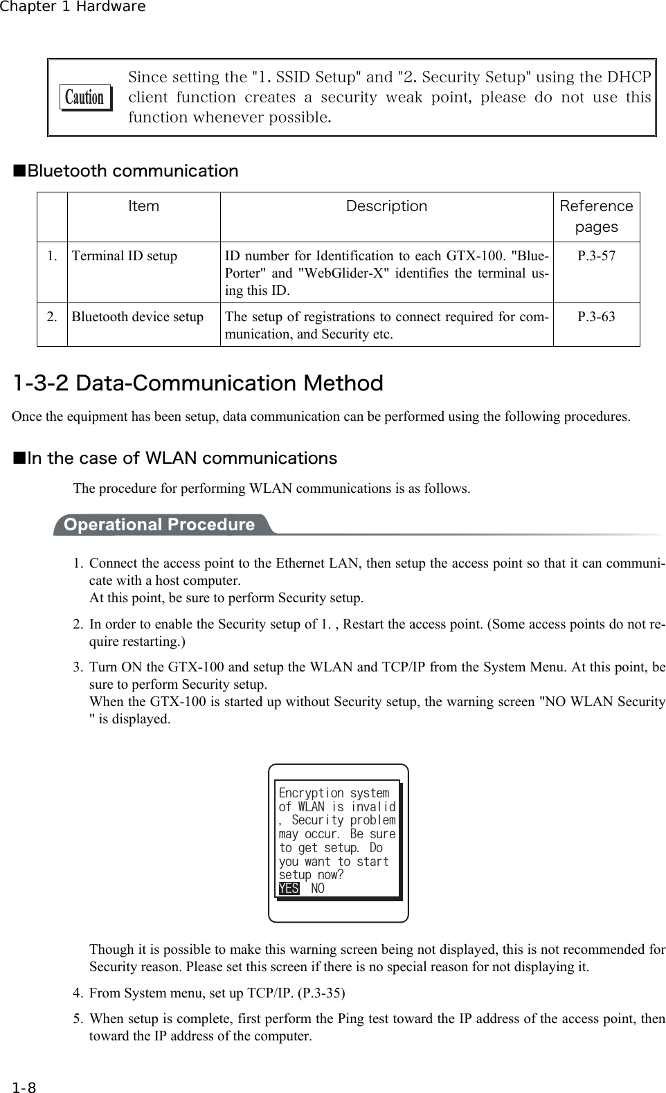
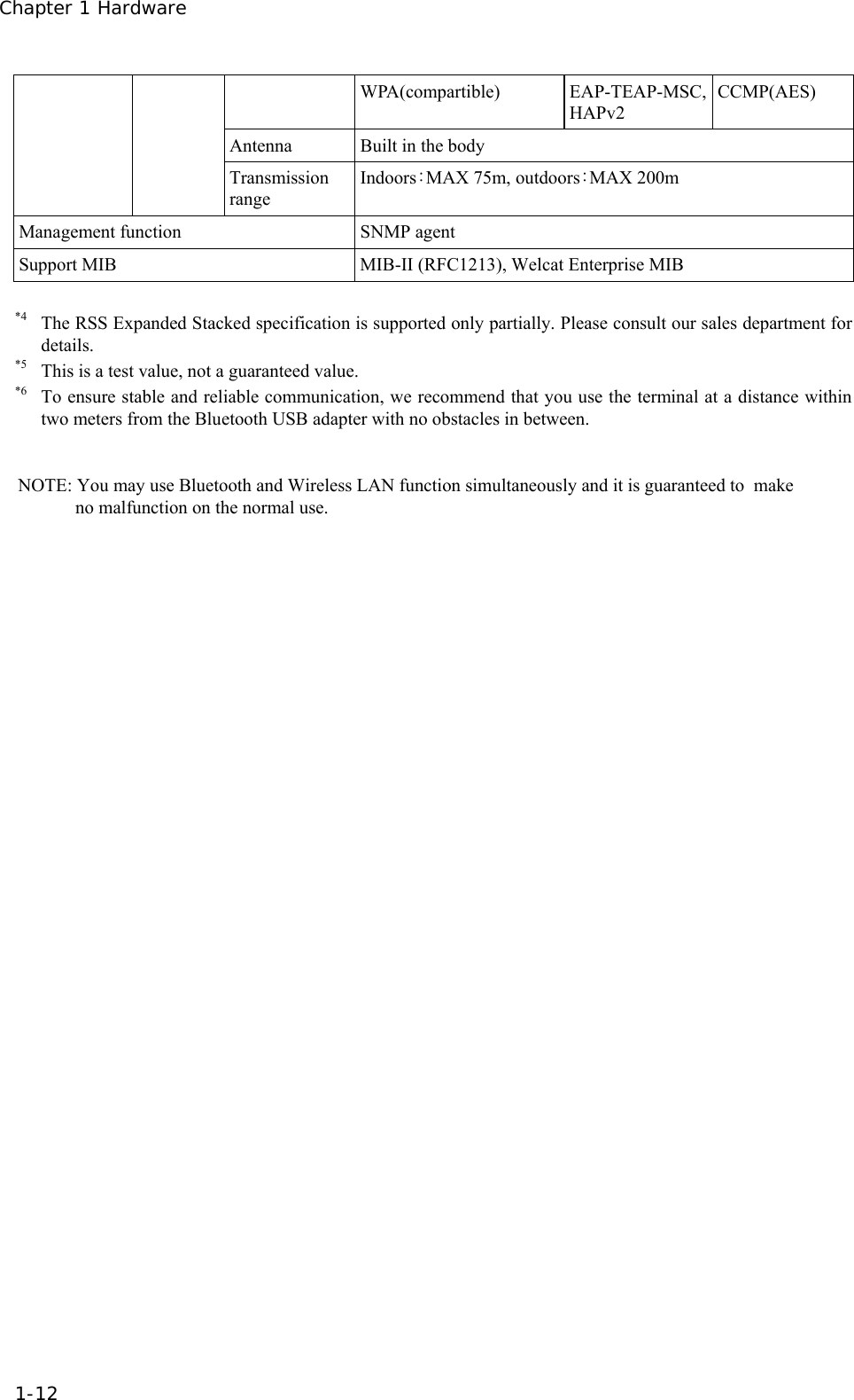
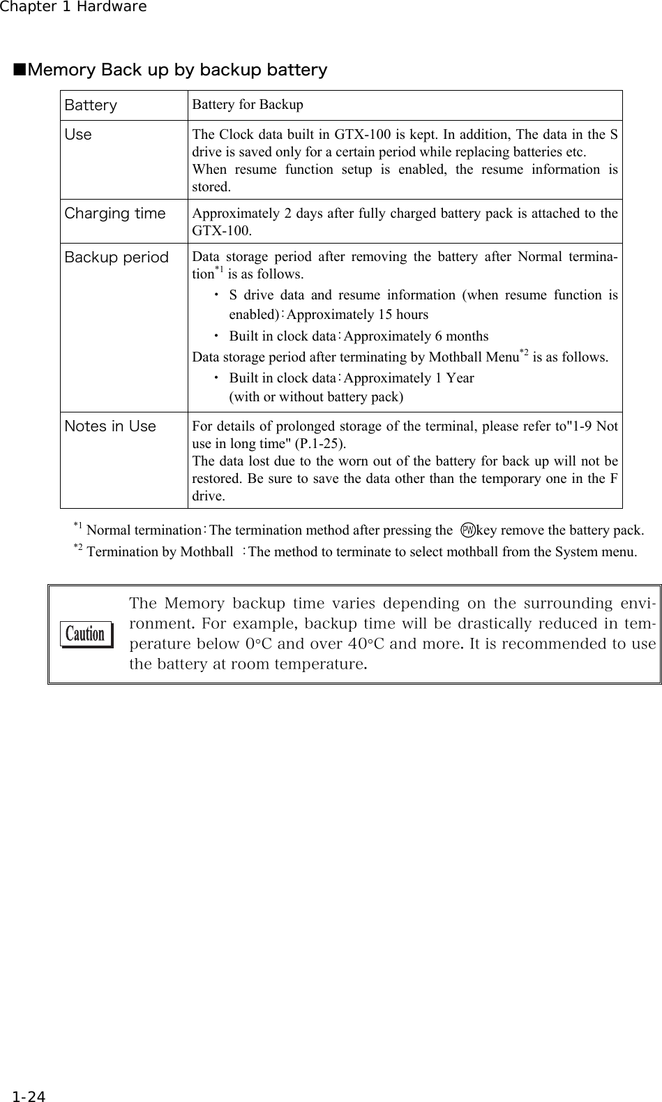
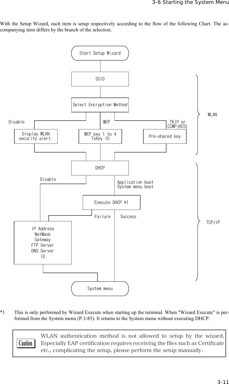
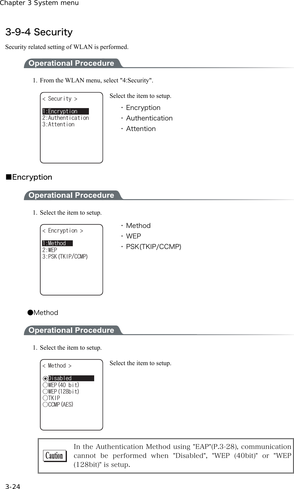
![Chapter 3 System menu 3-10 3-6-4 Executing Setup Wizard At the initial startup of the terminal, the setup wizard is executed to perform the minimum setup of the request for communication between the terminal and the server. 9K\CTF %QOOWPKECVKQPUGVVKPIECPDGFQPG5VCTVYK\CTF!YKVJIWKFCPEG;'501 Select either[Yes]or [No]. Select [Yes], then the wizard will be executed to perform the setup of WLAN and TCP/IP. Select [No], then the System menu will start up. When selecting [No] to skip the Setup Wizard, or, completing the setup to the last moment by executing Setup Wizard, the Setup Wizard will not startup from next time and after. Each item to be entered in the Setup Wizard can be set up each by each in the System menu. In addition, Setup Wizard can be arbitrarily executed from the System menu (P.3-85).](https://usermanual.wiki/Welcat/GTX100/User-Guide-859113-Page-65.png)
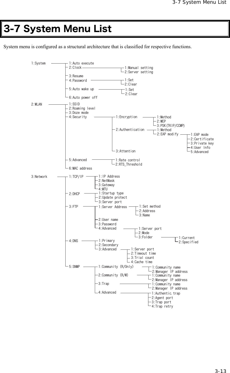
![Chapter 3 System menu 3-12 3-6-5 WLAN Security Alert When the WLAN Encryption Method is disabled, the dialog to alert the setup is displayed at the time of starting up. VQIGVUGVWR&Q[QWYCPVVQUVCTVOC[QEEWT$GUWTGUGVWRPQY!;'501QH9.#0KUKPXCNKF5GEWTKV[RTQDNGO'PET[RVKQPU[UVGO Select either from [Yes] or [No] Select [Yes], moves to "2:WLAN". Select [No], System menu is displayed. When the resume is enabled, this dialog is not displayed.](https://usermanual.wiki/Welcat/GTX100/User-Guide-859113-Page-67.png)
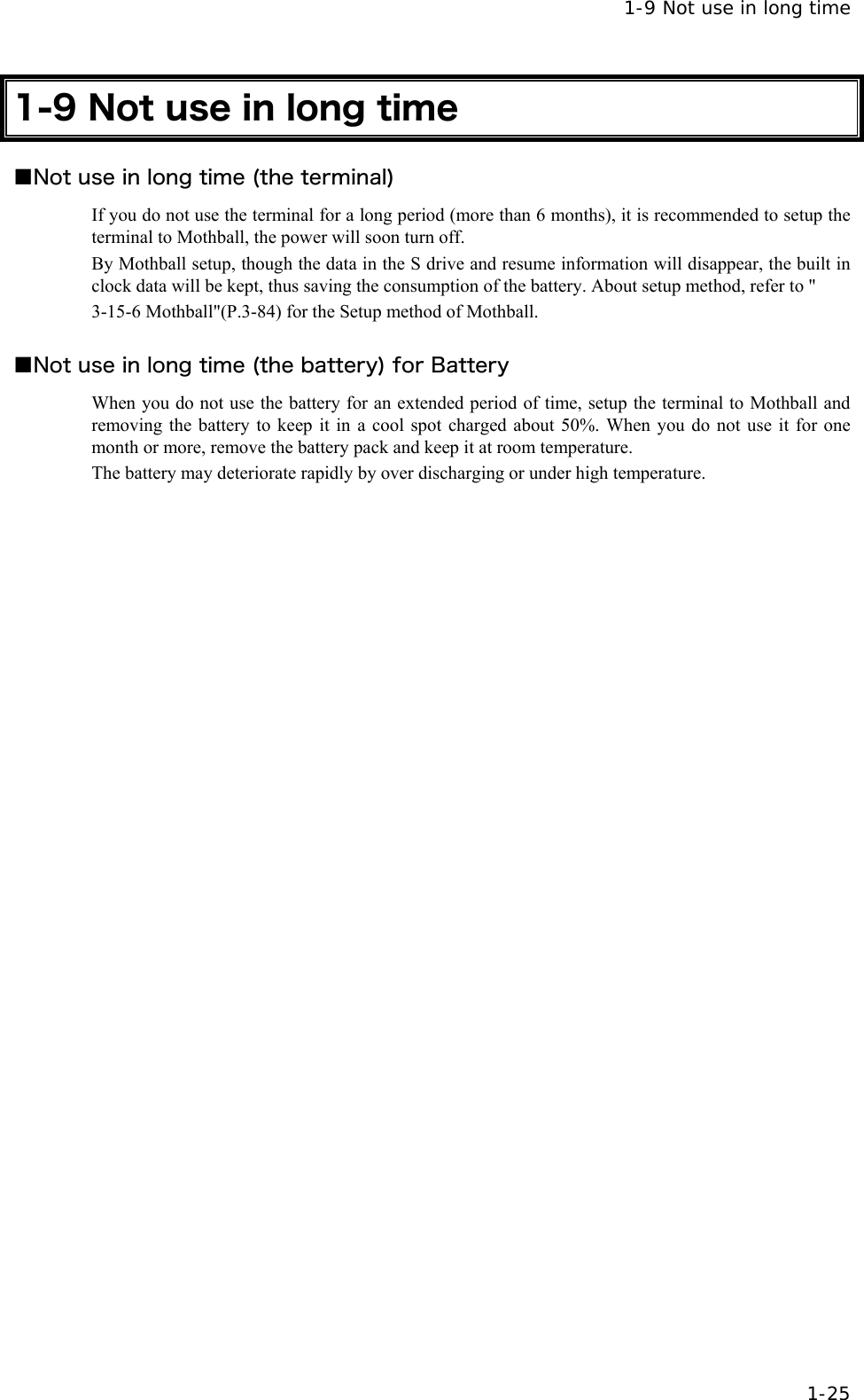
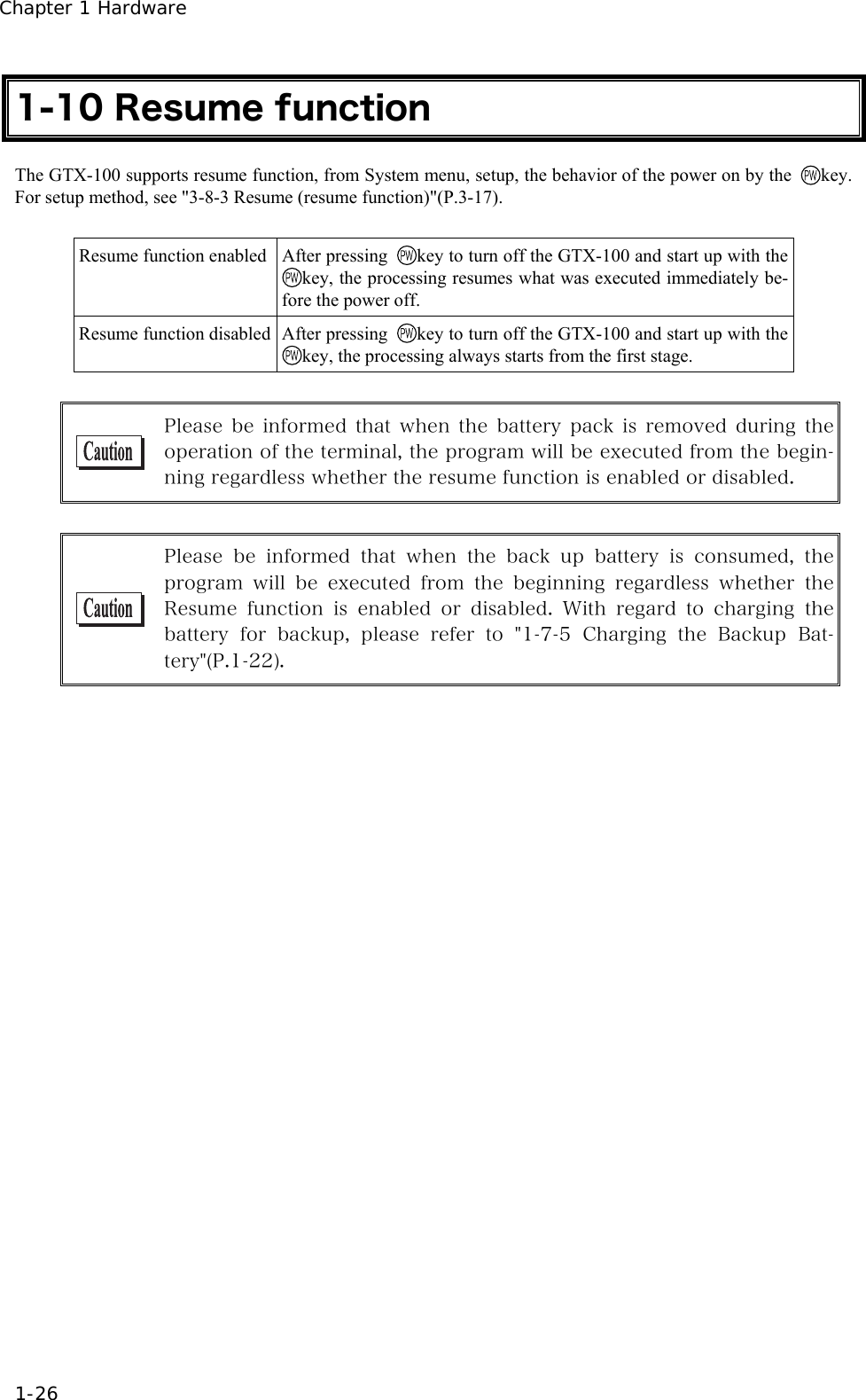
![3-8 System Setup Menu 3-17 1. Receiving the time data from the DHCP of "WebGlider-X" Network Manager. 5GTXGTUGVVKPI &*%25GTXGT%QPPGEVVQ%QORNGVGF1- Press key or key to return to check the current time. %QPPGEVVQ6KOGCESWKUKVKQPHCKNGF4GVT[!5GTXGTUGVVKPI 4'64;%#0%'. When receiving is failed, the screen on the left is displayed. [Select RETRY], to receive the Time data from the server again. Select [CANCEL], or Press the key to cancel setup and return to Current time. 3-8-3 Resume (resume function) The GTX-100 supports a resume function. The resume function can be enabled through the System menu and if selected, the next time the key is pressed on the GTX-100, the resume function will be used. Resume mode ON after the GTX-100 is powered OFF, the next time the key is pressed, it will resume operation where it was just before the power was turned OFF. For details of the resume function, please refer to the "1-10 Resume func-tion"(P.1-26). ●Resume mode ON After the GTX-100 is powered OFF, the next time the key is pressed, it will resume operation where it was just before the power was turned OFF. (Power ON, pressing the key while pressing the scan key to cancel resume mode) ●Resume Fail 4GUWOGHCKNJKVCP[MG[5VCTVWUWCN Resume setup will fail when the power OFF by removing the bat-tery and without pressing the key.](https://usermanual.wiki/Welcat/GTX100/User-Guide-859113-Page-72.png)
![3-8 System Setup Menu 3-19 ■Password setting 1. Input a new password. 0GYRCUUYQTF2CUUYQTFUGVVKPI 0GYRCUUYQTFCICKP Password should be alphanumeric characters from 4 to 30, Up-per-case character/Lower-case character are distinguished. Input a new password, then, press the key. 2. Input the password again. 0GYRCUUYQTF2CUUYQTFUGVVKPI CDEF0GYRCUUYQTFCICKP After the password is entered, confirm by pressing the key. ■Clearing a Password 1. From the confirmation dialog, select[Yes]. 2CUUYQTFENGCT 2CUUYQTFENGCT!;'501 The setup password is erased. Select [No], or press the key, and clear to stop.](https://usermanual.wiki/Welcat/GTX100/User-Guide-859113-Page-74.png)
![3-8 System Setup Menu 3-21 ■Schedule Clearing 1. From the confirmation dialog, select[Yes]. 5EJGFWNGENGCT 9QWNF[QWNKMGVQENGCTUEJGFWNG!;'501 The setup Schedule is erased. Select [No], or Press the key to stop clearing. 3-8-6 Auto power off Auto power off is a function to make the power OFF automatically when there is no operation performed for a certain period. 1. From the System setup, then select "6:Auto power off". ᵘᵚ5GE#WVQRQYGTQHH ǽ)WKFCPEG( Input the Auto power off time. The time allowed to setup is from 0060 seconds to 3600 seconds. In addition, when set to 0000 seconds, the Auto power off is disabled.Press the key, and, setup value related guidance is displayed.](https://usermanual.wiki/Welcat/GTX100/User-Guide-859113-Page-76.png)
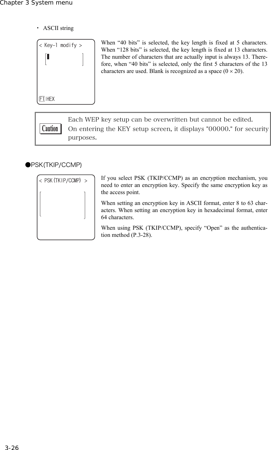
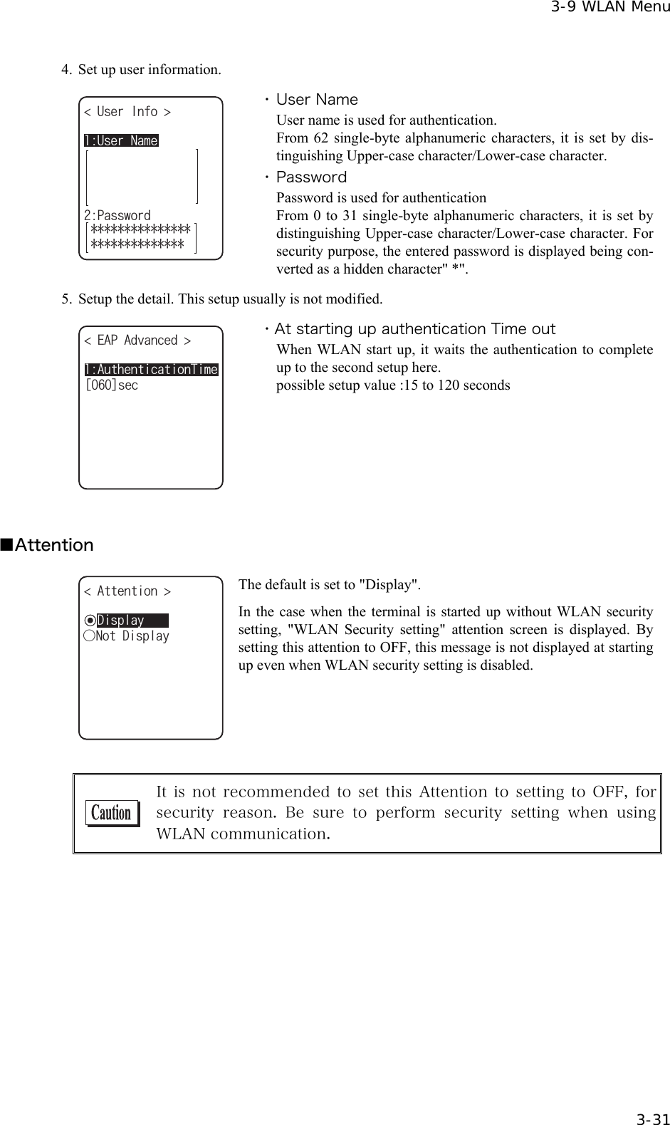
![3-9 WLAN Menu 3-25 ●WEP(Wired Equivalent Privacy) Since IEEE802.11b/g is a general wireless standard, it may be easily intercepted by a third person. The danger of data being intercepted between an access point and a terminal (GTX-100) is avoidable by using WEP, which is the standard of encryption of wireless communication. GTX-100 is compliant with two kinds of WEP keys (common key), "40 bits (also called 64 bits)" and "128 bits." 1. Select the item to setup. 6Z-G[+&ǽ-';9'2 Dz-';Dz-';Dz-';-G[/QFKH[ From the sub menu, select the item to setup. ・TxKey_ID Select the ID used for transmission from KEY1- KEY4 set in the next paragraph " KEY setup." This becomes effective if the WEP settings are set to other than "Disabled." Communication is possible only if the contents of both the WEP key of selected Tx KEY_ID and the access point WEP key are the same, and if the contents of both the Transmit KEY WEP key set on the access point and the terminal's WEP key are the same. For example, when the Tx KEY_ID of a terminal is set to "2," the contents of the terminal WEP key 2 and the contents of the access point WEP key 2 need to be the same. On the other hand, when an access point Transmit key is set to "3," the contents of the access point WEP key 3 and the contents of the terminal WEP key 3 need to be the same. ・KEY Setup You need to set the contents of each WEP key (1, 2, 3, 4). You can set a WEP key in either HEX string format (0 to 9 and A to F) or ASCII string format. Use the [F1] key to toggle between these formats. If the trigger key is pressed, the setup can be done by scanning a barcode. ・ HEX string (default) -G[OQFKH[ #5%++( When “40 bits” is selected, the key length is fixed at 10 characters. When “128 bits” is selected, the key length is fixed at 26 characters. The number of characters that are actually input is always 26. There-fore, when “40 bits” is selected, only the first 10 characters of the 26 characters are used.](https://usermanual.wiki/Welcat/GTX100/User-Guide-859113-Page-80.png)

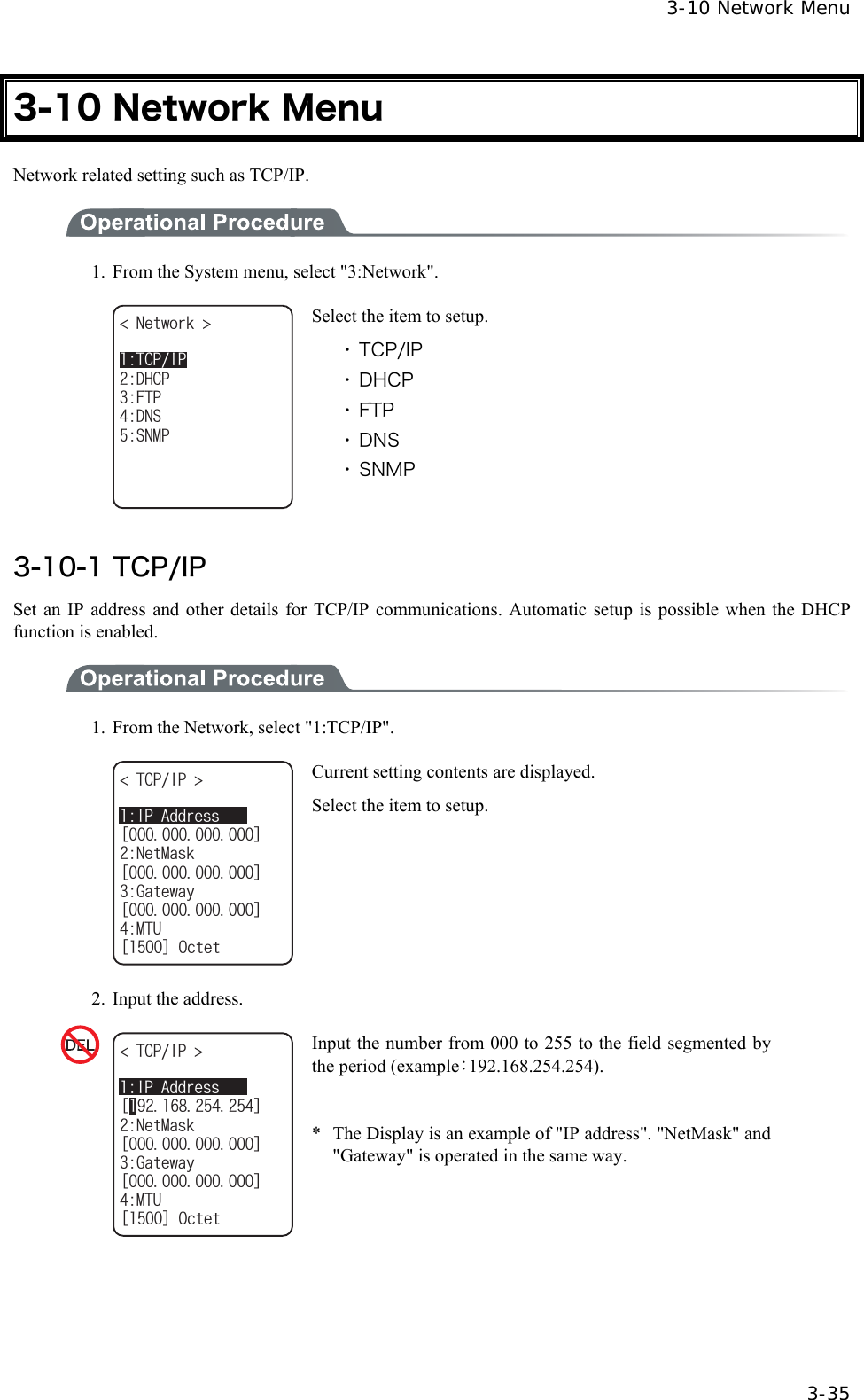
![Chapter 3 System menu 3-36 ・IP address Set the IP address assigned by the network administrator. Set a unique IP address to each of the GTX-100 terminals connected to the same network. ・NetMask (Subnet mask) Set the subnet mask assigned by the network administrator. Since a subnet mask specifies which network you belong to, it should set up along with the IP address. ・Gateway (Default gateway) Set the address of the default gateway. Setup is required when connecting to a different network through a router. ・ MTU The maximum length of IP packet. 1500 octets (bytes) is common for Ethernet. In such cases as being used over the routers, this value should be modified according to the communication me-dia. Please ask the network administrator about the value settings for different items. When the status of the IP address is [000.000.000.000],the WLAN communication is unable to be executed. Please ask the network administrator about the value settings for different items. From the "Startup type" of DHCP setting (P.3-37), in case either "Application boot" or "System menu boot" is selected, the value except for MTU can only be confirmed but unable to be modified. 3-10-2 DHCP Set the DHCP client function that is used for automatic setup of TCP/IP and various set items. 1. From the Network menu, select "2:DHCP." &*%2 5GTXGTRQTVᵘᵚ7RFCVGRTQVGEVǽ'ZGEWVG5VCTVWRV[RG( Select the item to setup. ・ Startup type ・ Update protect ・ Server port](https://usermanual.wiki/Welcat/GTX100/User-Guide-859113-Page-91.png)
![3-10 Network Menu 3-37 ■Startup type 1. Select the item to setup. 5VCTVWRV[RG Dz5[UVGOOGPWDQQVDz#RRNKECVKQPDQQVǽ&KUCDNGF ・ Disabled (Factory setup) DHCP is not executed when the terminal started up. ・ Application boot DHCP is executed before the application is executed. The application file is selected from <System menu>[1:System], and then[2:Auto execute], DHCP function is executed before application , after the terminal started up. In addition, when the application is started up from <File menu>, DHCP is not executed. ・ System menu boot DHCP is executed before System menu is started up. The Sys-tem menu is selected from <System menu>[1:System], and then[1:Auto execute], DHCP function is executed before Sys-tem menu is started up , after the terminal started up. ■Update protect Following information unique to the terminal is setup so as not to be modified, before executing DHCP function. ・ IP address ・ NetMask ・ Gateway ・ ID In the case when the check is applied to IP address (IP address up-date is prohibited), the IP address, which has set up at the terminal, is not modified. Be sure to use confirming that the there is no host with the same IP address on the Network. ■Server port number DHCP server port is setup (Factory setup:08067). If you do not execute the automatic setup, which is unique to the GTX-100, and want to use existing server only to perform the assigning of IP address, the value is modified (the well known port is 67). The port number of the DHCP server of "WebGlider-X" Network manager is 08067 as default. This is to avoid a competition with other DHCP servers working in the same network. ■Execute Press the key, and, DHCP is executed immediately, regardless of "Startup type"(P.3-37).](https://usermanual.wiki/Welcat/GTX100/User-Guide-859113-Page-92.png)

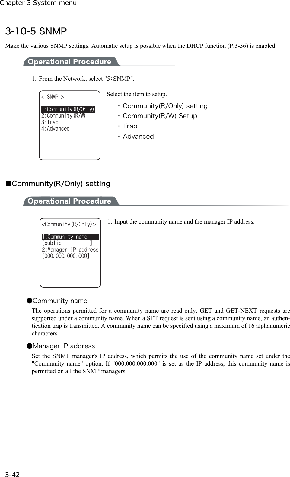
![3-10 Network Menu 3-43 ■Community(R/W) Setup %QOOWPKV[PCOGᵘRTKXCVGᵚ%QOOWPKV[49 /CPCIGT+2CFFTGUUᵘᵚ 1. Input the community name and the manager IP address. ●Community name The operations permitted for the community name are "Read-Write". GET, GET-NEXT and SET request are supported under a community name. The community name can be specified using a maximum of 16 alphanumeric characters. ●Manager IP address Set the SNMP manager's IP address, which permits The use of the community name set under the [community name]option. If "000.000.000.000" is set as the SNMP manager's IP address, this com-munity name is permitted on all the SNMP managers. ■Trap setting %QOOWPKV[PCOGᵘ9GNECVᵚ6TCR /CPCIGT+2CFFTGUUᵘᵚ 1. Input a community name and a manager IP address. ●Community name Set a community name for the Trap. A community name can be specified using a maximum of 16 alphanu-meric characters. ●Manager IP Address Set the SNMP manager's IP address to which the Trap should be transmitted. Trap is not transmitted if the IP address of "000.000.000.000" has been set.](https://usermanual.wiki/Welcat/GTX100/User-Guide-859113-Page-98.png)
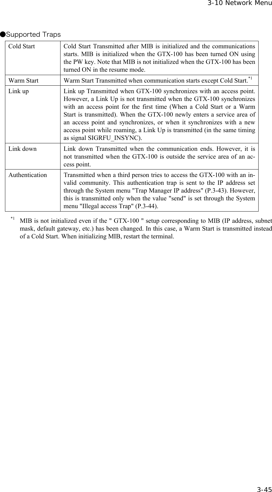
![Chapter 3 System menu 3-44 ■Advanced #WVJGPVKE6TCRǫ5GPF#FXCPEGF #IGPVRQTVᵘᵚ6TCRRQTVᵘᵚ6TCRTGVT[ᵘᵚ ●Authentic. trap Set the action of authentication trap to either "send" or "don't send" when access is recognized except from the community name and SNMP manager's IP address set in "1: Community (R/Only)" and "2: Community (R/W)." This Trap is sent to the SNMP manager, which is set in "2:Target address." ●Agent port The port number to communicate with SNMP manager. The well-known port is 161. ●Trap port The port number to transmit the Trap. The well-known port is 162. ●Trap retry The number of times Trap transmission retrial. ■About SNMP ・ GTX-100 can be managed by using Our "WebGlider-X"(WBG-001W). ・ SNMP-PDU(Protocol Data Unit) conforms to SNMPv1. ・ GTX-100supports the management of the objects in the following MIB group. [1.3.6.1.2.1.1] MIB2-System [1.3.6.1.2.1.2] MIB2-Interfaces [1.3.6.1.2.1.4] MIB2-IP [1.3.6.1.2.1.5] MIB2-ICMP [1.3.6.1.2.1.6] MIB2-TCP [1.3.6.1.2.1.7] MIB2-UDP [1.3.6.1.2.1.11] MIB2-SNMP [1.3.6.1.4.1.12392] Welcat Enterprise MIB Welcat Enterprise MIB is described by ASN.1 format. Welcat Enterprise MIB is included in the optional "WebGlider-X". (About details, please con-tact our sales department.)](https://usermanual.wiki/Welcat/GTX100/User-Guide-859113-Page-99.png)
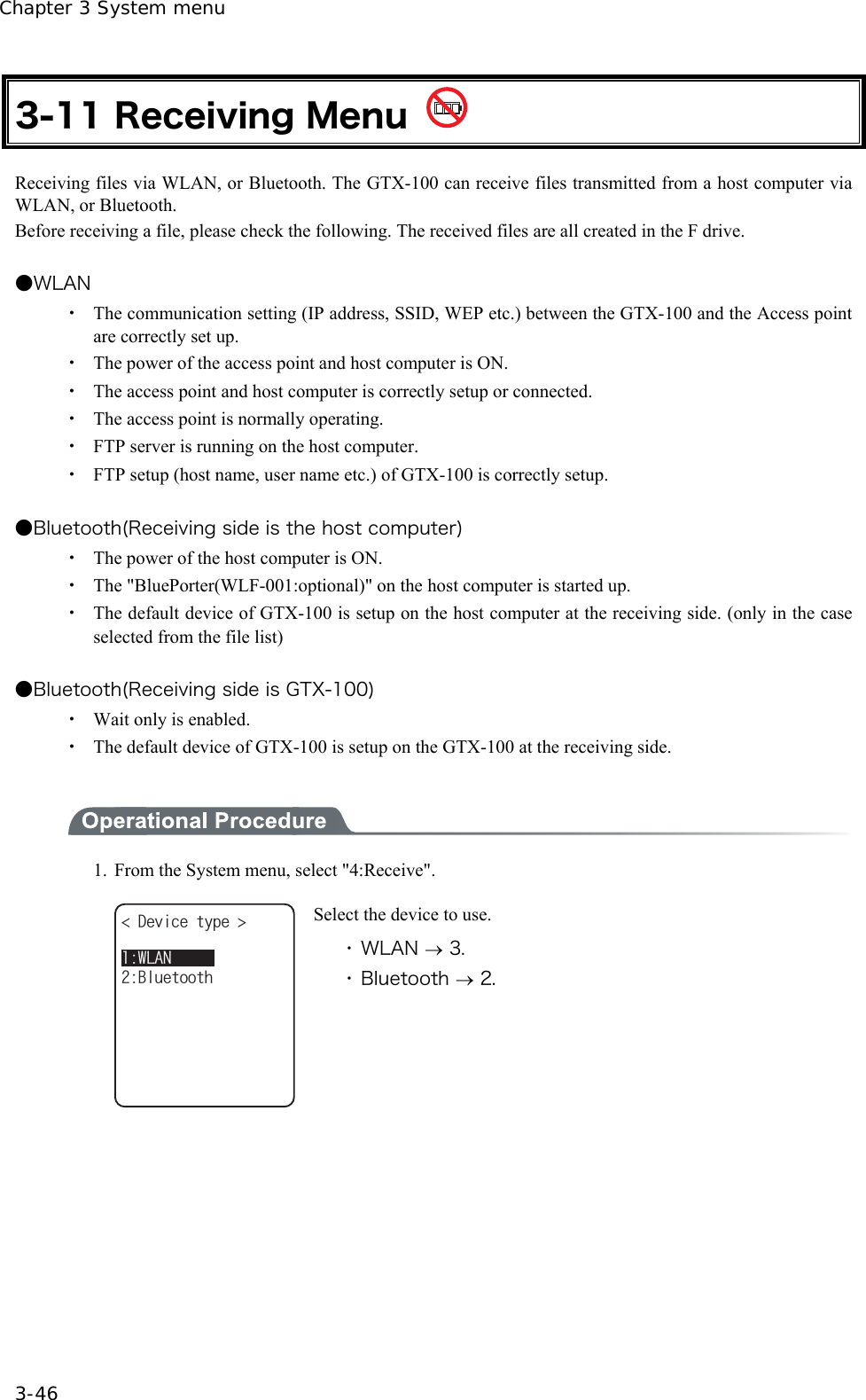
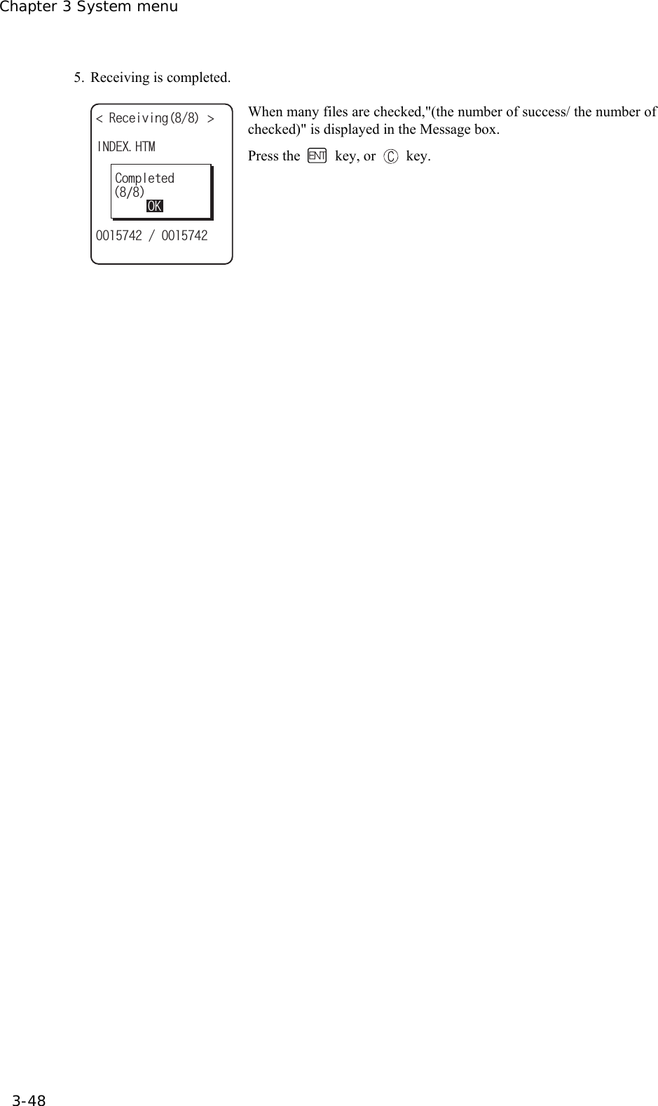
![3-11 Receiving Menu 3-47 2. Selecting receiving method. 4GEGKXKPIOGVJQF 9CKV)6:9CKV2%5GNGEVHTQONKUV Select "1: Select from list " to obtain the file list from the transmis-sion side. The receiver side can select the file to receive from the list.Select "2:Wait(PC)" or "3:Wait(GTX)”, then get into receiving wait-ing status immediately. If it is the transmission from the host com-puter select "2:Wait(PC)", when it is from GTX, Select "3:Wait(GTX)". The receiving file depends on the transmission side. ・ 1:Select from the file list→ 3 ・ 2:Wait(PC), 3:Wait(GTX)→ 4. 3. Acquire the file list, and select receiving file. (KNGNKUV ǫ9GNECVDORǫ9IZDQWVǫKPFGZJVOǫZKVQWVǫ/CUVGTVZVǫ+VGO/CUVGTVZVǽ4GEGKXGǽ/GPWǫ$CTEQFGTGCFYCX( (4GEGKXGKV!;'50Q Apply checks to the check box of the receiving file. Press the key, and Receiving Confirmation dialog is displayed. In this case, if there is no file that the check is applied, Selected file is received. Select from[Yes][No]. In addition, Press the key, and [No] is selected. (KNGNKUV ǫ9GNECVDORǫ9IZDQWVǫKPFGZJVOǫZKVQWVǫ/CUVGTVZVǫ+VGO/CUVGTVZVǽ4GEGKXG/GPWǫ$CTEQFGTGCFYCX( (#NNEJGEMGUCRRNKGF#NNEJGEMGUTGOQXGF(WNNPCOG Press the key, and Sub menu to operate the file lists displayed. ・"Full name" Selected file name is displayed. ・"All checks applied" Apply checks to all the check boxes of the file list. ・"All checks removed" Remove checks from all the check boxes of the file list. 4. Receiving start. 4GEGKXKPI 9IZDQWV Receiving status is displayed. 4GEGKXKPI HKNGPCOGF9):$176#NTGCF[EQPVCKPUC4GRNCEGKV!;'501 When there is a same file name as that of receiving file, overwriting confirmation dialog is displayed. Select[Yes]or [No]. In addition, press the key, and [No] is selected.](https://usermanual.wiki/Welcat/GTX100/User-Guide-859113-Page-102.png)
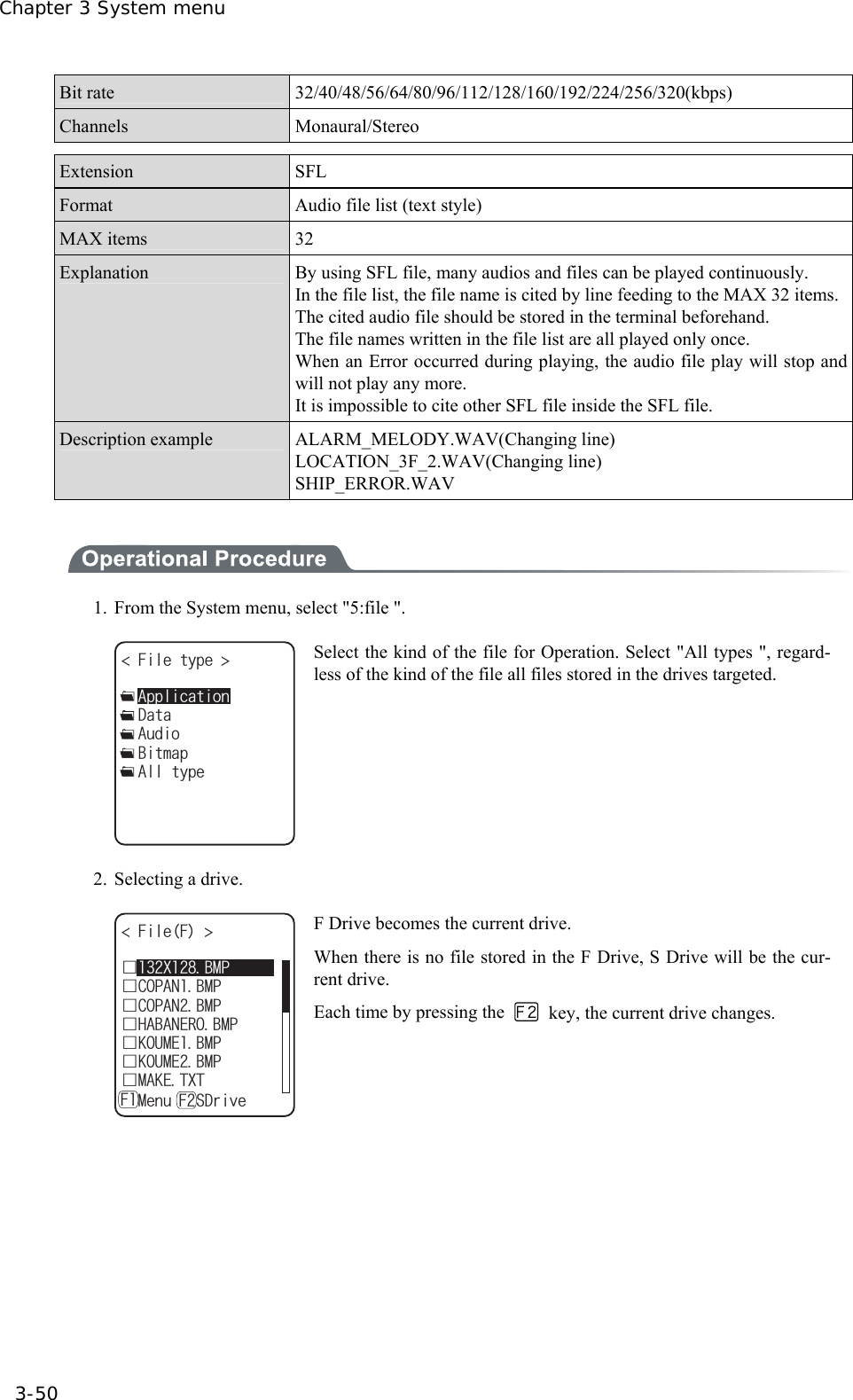
![3-12 File Menu 3-49 3-12 File Menu By searching the targeted file, varieties of operations such as transmission and Deletion are performed. Select the file for operation from the classified file list in each drive. The files are recognized by the extensions (3 characters following after the period of the file name), and classi-fied as below. Extension Kind of a file OUT Application WAV, MP3, SFL Audio BMP Bitmap Others Data Operation is that can be executed are as follows. There are operations that are related to some specific files and the operation enabled in all files. Operation About Execute*1 Starting up the application. Only the application files can be operated. Play*1*3 Play audio file. Only audio files can be operated. Viewer*2 Bitmap images displayed. Only bitmap files can be operated. Properties Various kind of properties related to the file are displayed. Upload Uploading a file. Delete Deleting a file. Test Check if a file is broken or not. All checks applied. Apply checks on all check boxes in the file list. All checks removed Remove all checks of the check box in the list. *1 The file in the S drive Operation is disabled. *2 Supported Bitmap file is as follows. Format Windows Bitmap monochrome image Size 132×128 pixel fixed *3 Supported audio file is as follows. Extension WAV Format Windows Standard WAVE Format Audio sampling rate 8000/11025/16000/22050/44100/48000[Hz] Channels Monaural Audio samples size 16bit Audio style PCM Extension MP3 Format MPEG-1 Audio Layer-3 Audio sampling rate 44100/48000[Hz]](https://usermanual.wiki/Welcat/GTX100/User-Guide-859113-Page-104.png)
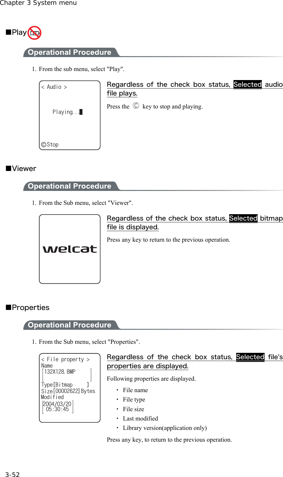
![3-12 File Menu 3-51 3. File operation. (KNG( ǫ6GU$/2ǫ%12#0$/2ǫɮʽʑʍɹʃ*6/ǫʷʽɺʟɫɮʵʗǫ/#-'6:6ǽ/GPWǽ5&TKXG( (ǫ:$/2ǫ9):D1762TQRGTVKGU7RNQCF'ZGEWVG&GNGVG6GUV#NNEJGEMUCRRNKGF#NNEJGMEUTGOQXGF File alone check box operation (apply checks /remove checks) is performed by the key. For other operation, press the key, From the Sub menu, Select the Operation. ・ Execute ・ Play ・ Viewer ・ Properties ・ Upload ・ Delete ・Test ・ All checks applied ・ All checks removed ■Execute 1. From the Sub menu, select "Execute". (KNGGZGEWVG TGIKUVGTYKVJ#WVQGZGEWVG!;'5019QWNF[QWNKMGVQ Regardless of check box status, Selected application is executed. When an SFL file application to be executed is not registered in the Automatic Launch, register confirmation dialog is displayed. In addition, Press the key, and [No] is selected. After selecting, execute the program. To end the application, perform the operation specified for each application. After termination, whether the System menu is displayed again or, the power of the ter-minal turns off is depends on the application. When the battery lost its power, the alarm appears and the power of the terminal turns OFF. If you want to stop the application by force, press the key continuously for 10 seconds while it is running.](https://usermanual.wiki/Welcat/GTX100/User-Guide-859113-Page-106.png)
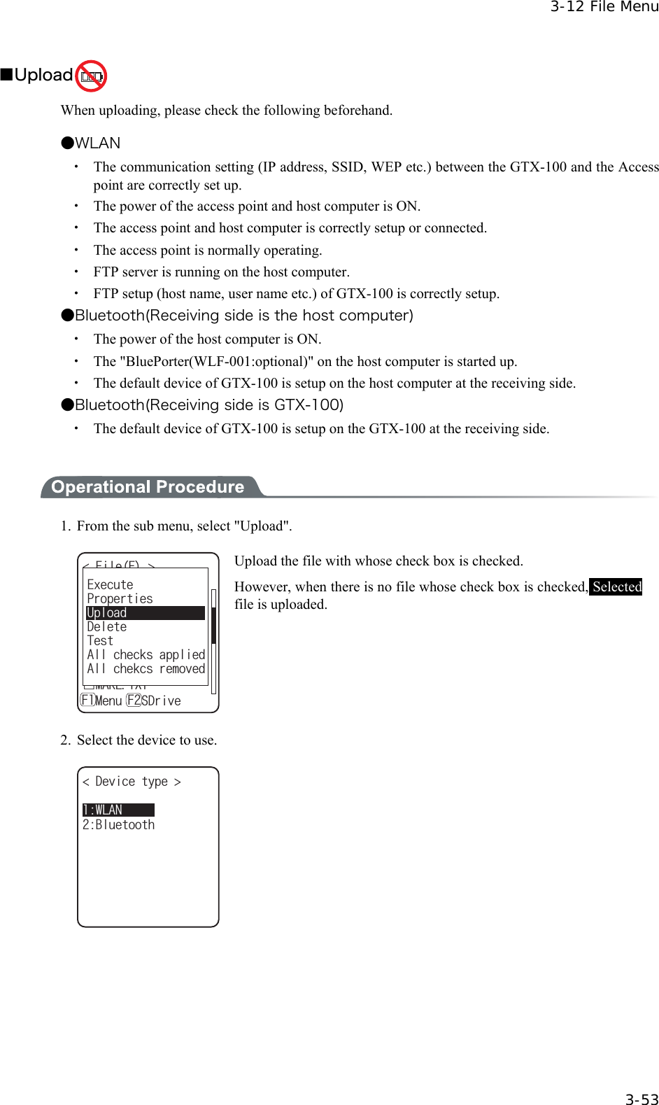
![Chapter 3 System menu 3-54 3. Upload start. 7RNQCFKPI +0&':*6/ Upload status is displayed. 4. Upload is completed. 7RNQCFKPI +0&':*6/ᴥᴦ1-%QORNGVGF When many files are checked, (the number of upload success / the number of checked items)" is displayed in the "Message box". Press the key, or key. ■Delete 1. From the sub menu, select "Delete". (KNGFGNGVG &GNGVGHKNGU!;'501 Delete the file whose check box is checked. However, if there is no checked file, Selected file is deleted. Confirmation dialog is displayed. Select[Yes]or [No]. In addition, Press the key, and [No] is selected.](https://usermanual.wiki/Welcat/GTX100/User-Guide-859113-Page-109.png)
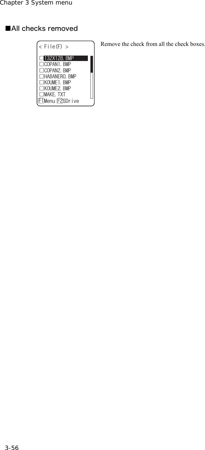
![3-12 File Menu 3-55 ■Test (KNG( ǫ6GU$/2ǫ%12#0$/2ǫɮʽʑʍɹʃ*6/ǫʷʽɺʟɫɮʵʗǫ/#-'6:6ǽ/GPWǽ5&TKXG( (ǫ:$/2ǫ9):D1762TQRGTVKGU7RNQCF'ZGEWVG&GNGVG6GUV#NNEJGEMUCRRNKGF#NNEJGMEUTGOQXGF Test the file whose check box is checked. However, if there is no checked file, Selected file is tested. (KNGVGUV (KNGKUDTQMGP&GNGVG!9IZDQWV;'501 When the tested file is broken, file delete confirmation dialog is dis-played. Select[Yes][No]. In addition, press the key, and [No] is selected. When[Yes]is selected, the file is deleted immediately. When [No] is selected, nothing will be performed. After the Select, restart the next file testing. If the broken file is used as it is, an unexpected accident such as the application's running out of control and so on. It is strongly rec-ommended to delete the broken file. ■All checks applied 1. From the Sub menu, select "All checks applied". (KNG( ǫ%12#0$/2ǫ*#$#0'41$/2ǫ%12#0$/2ǫ-17/'$/2ǫ-17/'$/2ǫ/#-'6:6ǽ/GPWǽ5&TKXG( (ǫ:$/2 Check all the check boxes.](https://usermanual.wiki/Welcat/GTX100/User-Guide-859113-Page-110.png)
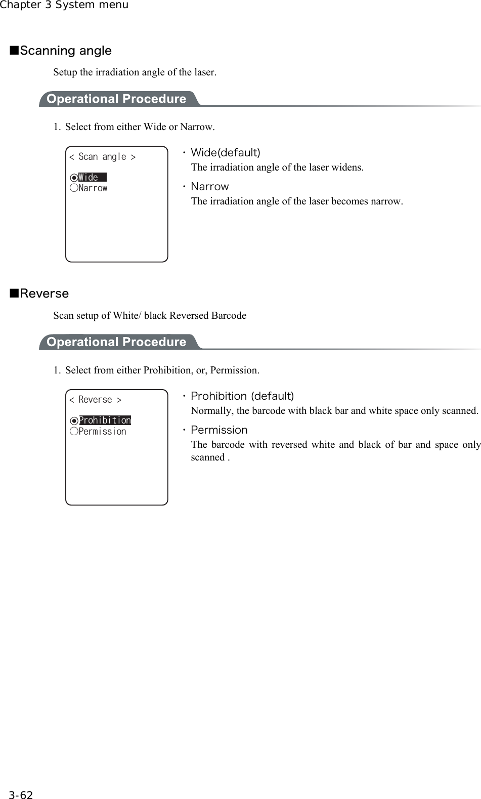
![3-14 Device Menu 3-61 ■Decode level Setup the permissible range of the Barcode scanning. When the Decode level is set to "strict", the barcode label checked strictly. For this reason the label of poor quality get difficult to scan, but the possibility of miss scanning be-comes low. On the other hand, when the Decode level is set to "loose", the barcode label of comparatively poor quality can be scanned, but the possibility of miss scanning becomes high. Be sure to check the digit number, data etc in the check digit of the software when the "loose" is set. 1. Decode level Adjustment. ǽ0QTOCN&GEQFGNGXGN Dz.QQUG)WKFCPEGDz5VTKEV( The level can be adjusted to 3 stages, "Strict", " Normal", and “Loose". The relationship between level value and easiness for scan-ning is as follows. The scan level and miss scanning level are proportionate. Level value Scan (miss scanning) rate Strict Strict (difficult to miss scan) Normal ↑↓ Loose Loose (easy to miss scan) Press the key, and the guidance for setup value is dis-played. ǽ0QTOCN&GEQFGNGXGN Dz.QQUG)WKFCPEGDz5VTKEV(JKIJ+UKVCNNTKIJV!OKUTGCFKPIDGEQOGU;'501VJGTCVGQHVJCPVJGUVCPFCTF5KPEGKVKUNGUUNGXGNVQTGEQOOGPF When the level is going to setup to "loose", the guidance for attention about miss scanning is displayed. Se-lect[Yes][No].In addition, press the key, to select [No].](https://usermanual.wiki/Welcat/GTX100/User-Guide-859113-Page-116.png)
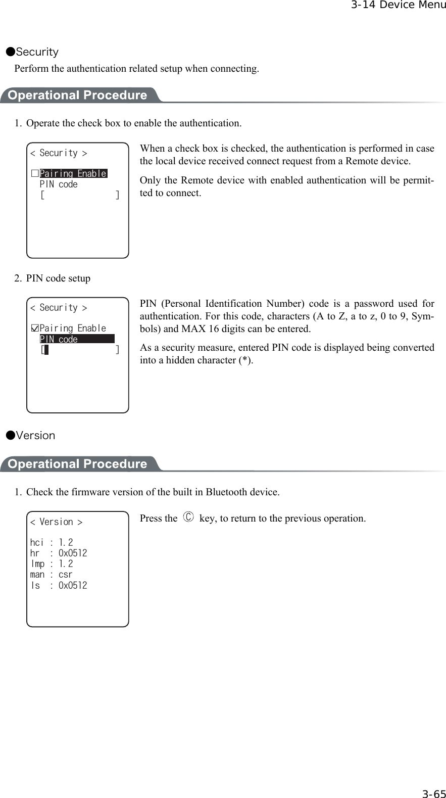
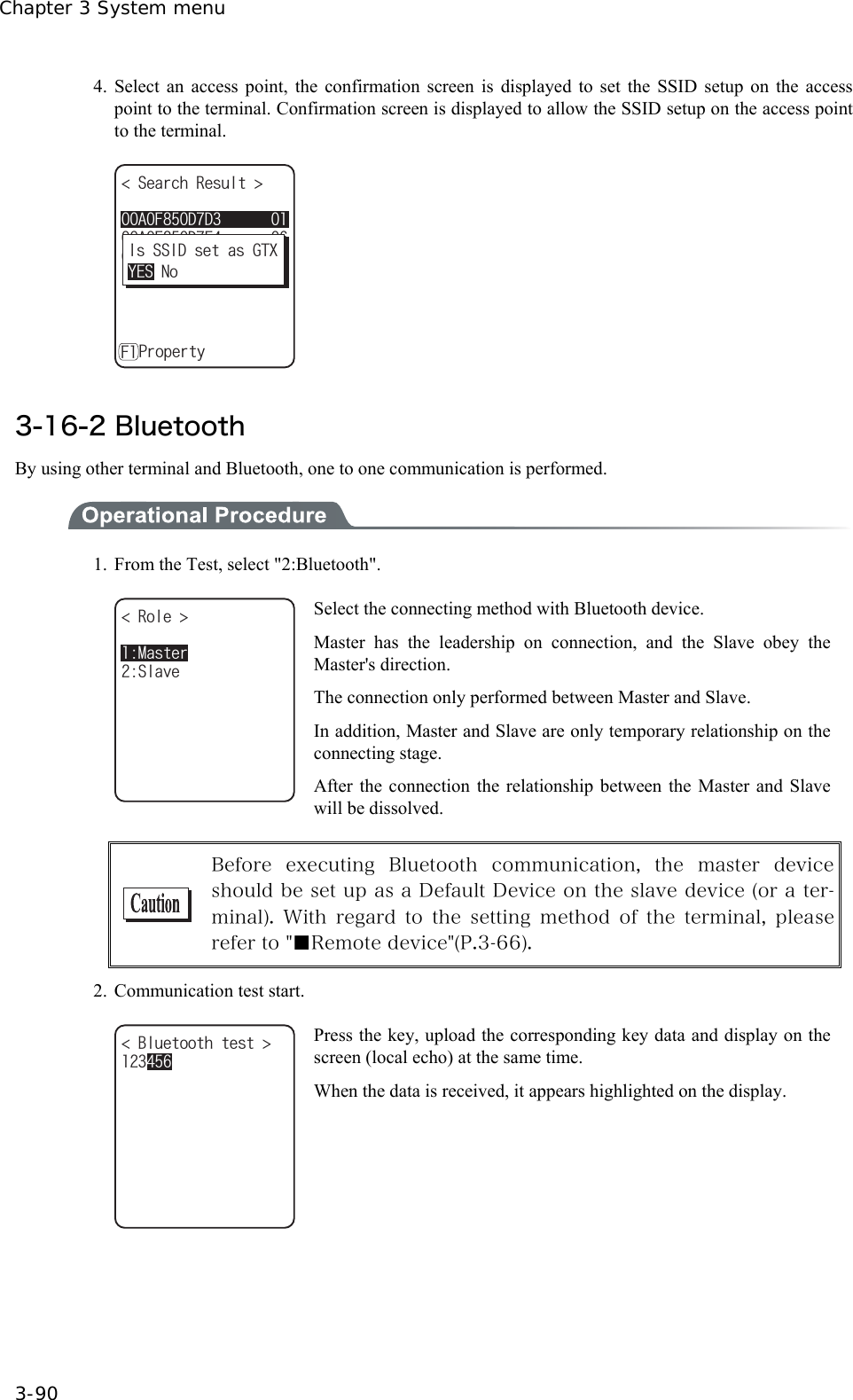
![Chapter 3 System menu 3-64 ■Local device Local device setup. 1. Select the item to setup. )6:2TQRGTV[ $&#FFTGUUᵘ#$##$ᵚ5GEWTKV[8GTUKQPǽ5CXG&GXKEGPCOG( ・ Device name ・ Security ・ Version As "BD Address" is fixed, setup contents cannot be changed. Only during the local device setting, the search from the Remote device is search is accepted. In other case, the search is not ac-cepted. )6:2TQRGTV[ $&#FFTGUUᵘ#$##$ᵚ5GEWTKV[8GTUKQPǽ5CXG&GXKEGPCOG(5CXGUGVVKPIU!;'501 The setup contents in each item are not saves as it is. In order to save the setup contents, press the key or key, and select [Yes] in the Save confirmation dialog. In addition, Press the key, and [No] is selected. ●Device name 1. Input the name of the Bluetooth device. 2TQRGTV[ $&#FFTGUU)6:ᵘ#$##$ᵚ5GEWTKV[8GTUKQPǽ5CXG&GXKEGPCOG( For device name, the alphanumeric characters MAX 30 characters, and the Upper-case character/Lower-case character is distinguished.](https://usermanual.wiki/Welcat/GTX100/User-Guide-859113-Page-119.png)
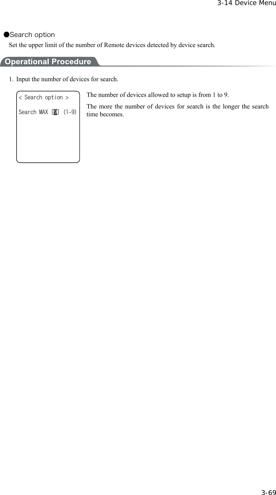
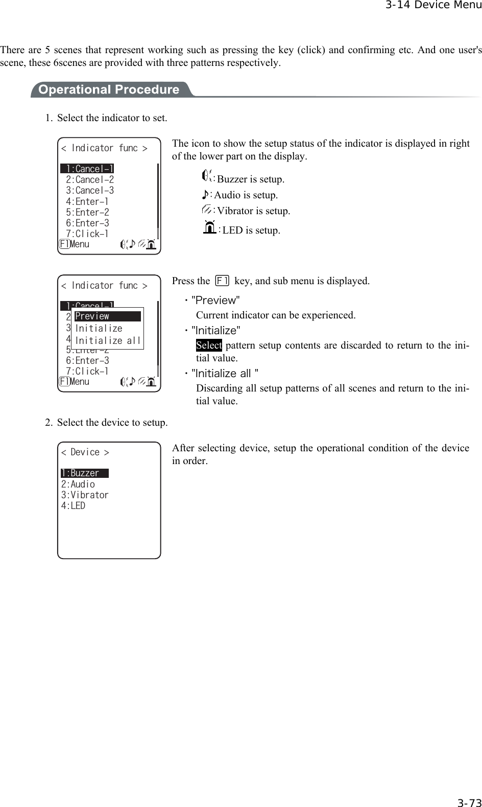
![Chapter 3 System menu 3-66 ■Remote device Remote device setup. 1. Select the item to setup. 4GOQVGFGXKEG 5GCTEJQRVKQPU5GCTEJHQTFGXKEGU&GXKEGNKUV ・ Device list ・ Search for devices ・ Serch options ●Device list Remote device properties to connect can be registered MAX 7 items. Once registered beforehand, you don't have to set the device properties for each connection. 1. Select the item number to register &GXKEGNKUV ǽǽǽǽǽǽǽ/GPWǽ(ᴥ0Q&GXKEGᴦᴥ0Q&GXKEGᴦᴥ0Q&GXKEGᴦᴥ0Q&GXKEGᴦᴥ0Q&GXKEGᴦᴥ0Q&GXKEGᴦᴥ0Q&GXKEGᴦ Select the item number, setup the device properties in order. When device properties have already registered, the device name is displayed to the right of the item number. When the device is not registered, [(No Device)] is displayed to the right of the item number. (Recognized as registered when the device name is of 1 character more, and the BD address is other than "00:00:00:00:00:00"). The device whose item number is displayed with to its left is a default device. In the System menu when connecting via Bluetooth, default device is connected to. &GXKEGNKUV ǽǽǽǽǽǽǽ/GPWǽ(ᴥ0Q&GXKEGᴦᴥ0Q&GXKEGᴦᴥ0Q&GXKEGᴦᴥ0Q&GXKEGᴦᴥ0Q&GXKEGᴦᴥ0Q&GXKEGᴦᴥ0Q&GXKEGᴦ'TCUG&GHCWNV Press the key, and sub menu is displayed. ・ "Default" Selected device to register is setup as a default device. ・ "Erase" Erase the registered device properties.](https://usermanual.wiki/Welcat/GTX100/User-Guide-859113-Page-121.png)
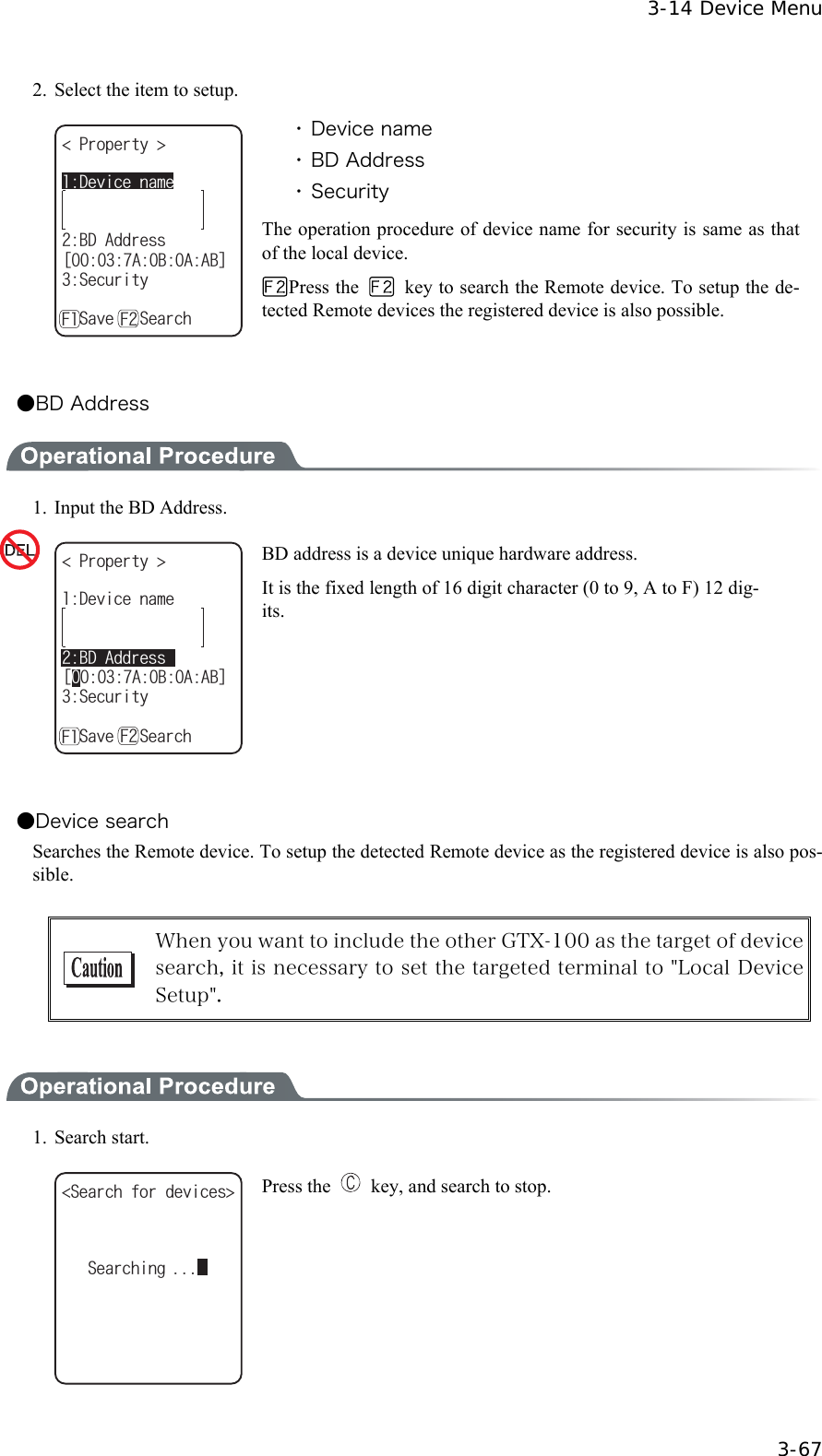
![Chapter 3 System menu 3-68 2. The search result list is displayed. 75$#FCRVQT5GCTEJTGUWNVU .CDGN2TKPVGTǽ2TQRGTV[( The device name list of the detected remote device is displayed. The device name that can be detected is limited to alphanumeric characters. Be sure not to use the Kana-Kanji as the device name of the host computer. 2TQRGTV[ 75$#FCRVQT$&CFFTGUUᵘ%&&$'ᵚ&GXKEGPCOG Press the key, and Selected Remote device's device name and BD address are displayed. Press the key, to return to the previous operation. 3. Select detected remote device. 75$#FCRVQT5GTCTEJTGUWNVU .CDGN2TKPVGTǽ2TQRGTV[(4GOQVG4GOQVG4GOQVG4GOQVG4GOQVG4GOQVG4GOQVG Press the key, and Selected Remote device's device name, BD address are displayed. Press the key to return to the previous operation. 4. Select the registered number of the registered device. 75$#FCRVQT5GCTEJTGUWNVU .CDGN2TKPVGTǽ2TQRGTV[(9QWNF[QWNKMGVQQXGTYTKVGKV!TGCF[TGIKUVGTGF;'50Q6JGTGOQVGJCUCN When the already registered number is selected, overwriting confir-mation dialog is displayed. Select [Yes][No]. In addition, press the key, and [No] is selected.](https://usermanual.wiki/Welcat/GTX100/User-Guide-859113-Page-123.png)

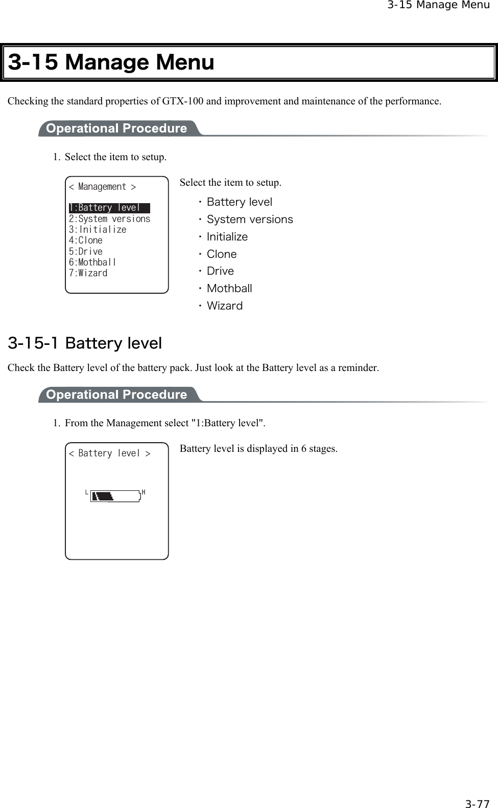
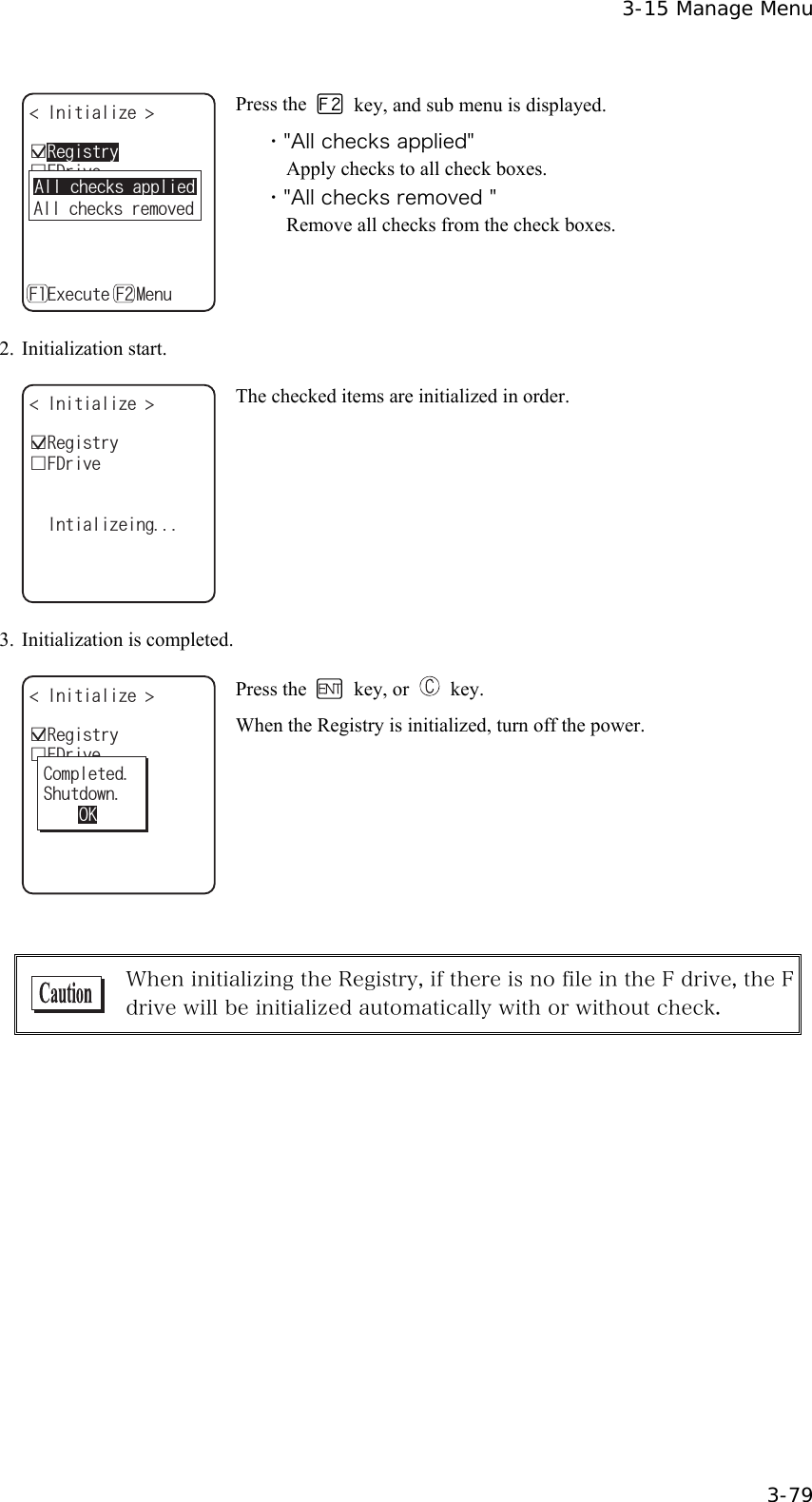
![Chapter 3 System menu 3-78 3-15-2 System versions The handy terminal system program (OS) version is displayed. 1. From the Management, select "2:System versions". 5[UVGOXGTUKQPU ǽǽǽǽǽǽǽǽǽǽ15 OS version is displayed. 3-15-3 Initialize Initializing the Registry and the drive. When the initialization is performed, the setup contents will return to the Factory setup and all files will be de-leted. When you perform the initialization take deepest cares with this understanding. 1. From the Management, select "3:initialize". +PKVKCNK\G ǫ5&TKXGǫ(&TKXGǽ'ZGEWVGǽ/GPW( (ǫ4GIKUVT[ Check the item that you want to initialize. If no item is checked, initialization cannot be executed. +PKVKCNK\G ǫ5&TKXGǫ(&TKXGǽ'ZGEWVGǽ/GPW( (ǫ4GIKUVT['ZGEWVG!;'501+HKPKVKCNK\GUGVVQCFGHCWNVQTCNNHKNGUCTGFGNGVGF Press the key, and execute confirmation dialog is displayed. Select [Yes] or [No]. In addition, press the key, and [No] is se-lected.](https://usermanual.wiki/Welcat/GTX100/User-Guide-859113-Page-133.png)
![Chapter 3 System menu 3-82 ■Copy 1. Initializing itself. %NQPGEQR[ ǽǽǽǽǽǽǽǽǽǽǽENQPGUGVVQCFGHCWNVQTCNN+HKVGZGEWVGFGNGVGF;'501HKNGUCTG'ZGEWVG! Execute confirmation dialog is displayed. Select from either [Yes] or [No]. In addition, press the key, and [No] is selected. 2. It is in the state the Clone is enabled. %NQPGEQR[ ǽǽǽǽǽǽǽǽǽǽǽTGCF[VQGZGEWVG6JG%NQPGKU1- Press the key or key to start Clone. 3. Confirm master display. %NQPGEQR[ ǽǽǽǽǽǽǽǽǽǽǽVJCOCUVGTKU2NGCUGEJGEMVJCV1-EQORNGVGF At the Copy terminal side, it cannot confirm that the Clone has com-pleted, be sure to confirm that the transfer has completed on the dis-play at the Master file. If the transfer from the Master file has not completes, execute the Clone again. Press the key or key. 4. Turn OFF the power. %NQPGEQR[ ǽǽǽǽǽǽǽǽǽǽǽ5JWVFQYP1- Press the key or key.](https://usermanual.wiki/Welcat/GTX100/User-Guide-859113-Page-137.png)
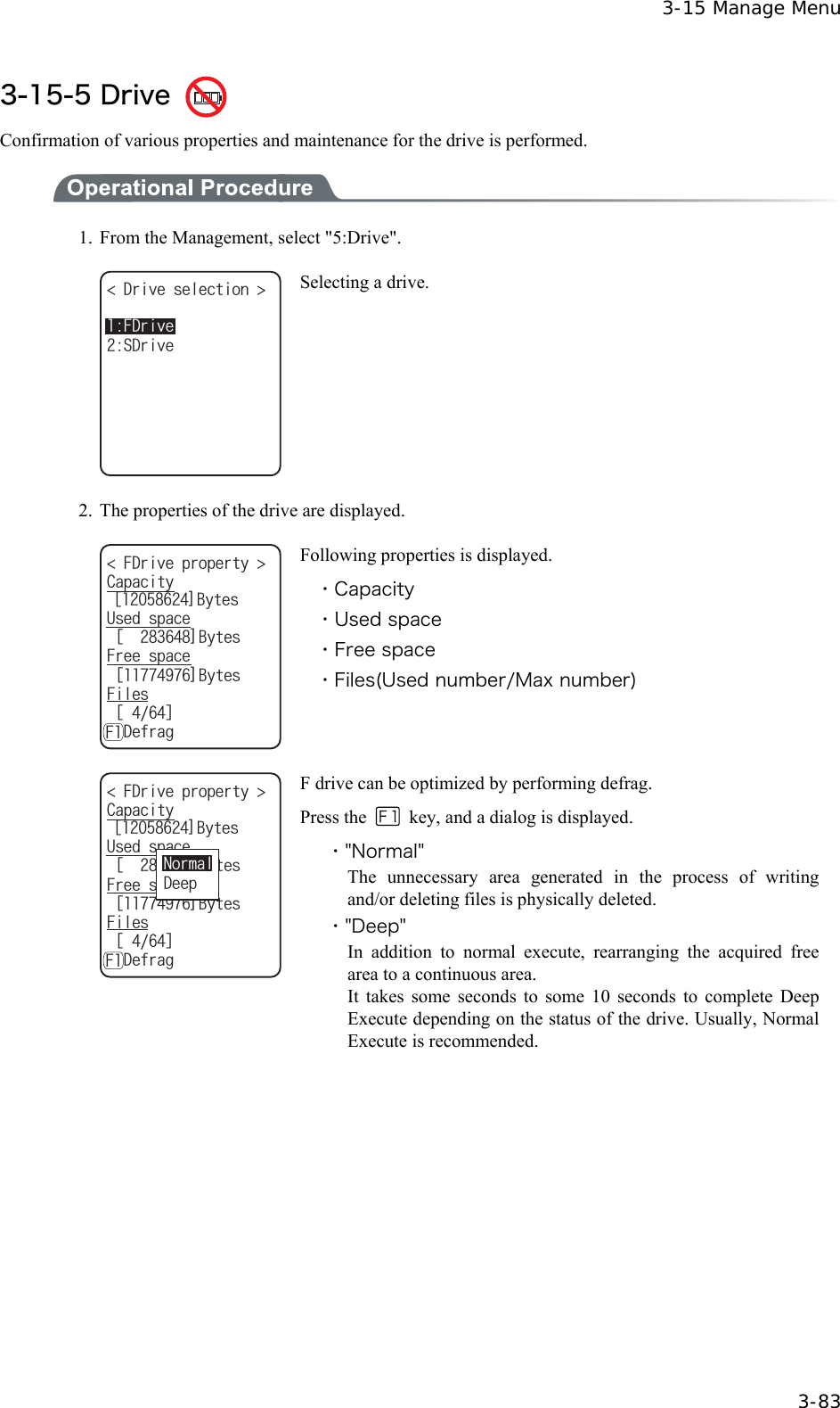
![Chapter 3 System menu 3-84 Writing or deleting files repeatedly in the F drive may cause the free space to be fragmented over time, ultimately making it impossible to store a large program file. Defragmentation is a process that reduces the amount of fragmentation and reclaims fragmented space into a continuous space. Defragmentation is usually not required because the system pro-gram maintains the F drive in a clean state by performing defrag-mentation automatically at each file update. However, if you tend to update files or perform other affecting actions frequently, frag-mentation may progress rapidly, soon making the free space in-adequate. If the F drive information indicates that the free space is very small relative to the total capacity and the space in use, we recommend that you perform “deep”defragmentation to create sufficient free space. While the system program is performing defragmentation auto-matically, it may require a longer time for file update or other ac-tions, this is not an abnormal condition. When the battery pack is removed in the course of defrag, a file or the System program may be corrupted. Never remove the battery pack during defrag. 3-15-6 Mothball Setup to suppress the consumption of the battery when the GTX-100 is not used for a long period. 1. From the Management, select "6:Mothball". /QVJDCNN UWRRTGUUKPI;'501TGUWOGCPFVJG5FTKXGCTGFGNGVG6JGEQPVGPVUQHFKPUVGCFQHEQPUWORVKQPQHCDCEMWRDCVVGT[ Execute confirmation dialog is displayed. Select [Yes] or [No]. Then, press the key, and [No] is selected. 2. Preparation for prolonged storage is complete. %QORNGVGF5JWVFQYP/QVJDCNN 1- Press the key or key. Turn OFF the Power.](https://usermanual.wiki/Welcat/GTX100/User-Guide-859113-Page-139.png)
![3-15 Manage Menu 3-85 3-15-7 Wizard The wizard executed at the initial boot of the terminal can be called back again. In order to perform communica-tion between the terminal and the server, the minimum necessary setting is enabled. 1. From the Management, select "7:Wizard". 9K\CTF %QOOWPKECVKQPUGVVKPIECPDGFQPG5VCTVYK\CTF!YKVJIWKFCPEG;'501 Select [Yes] or [No]. Select [Yes], then perform the setup of WLAN and perform the TCP/IP setup to execute the wizard. Select [No] to return to the pre-vious screen. See"3-6-4 Executing Setup Wizard"(P.3-10), for details.](https://usermanual.wiki/Welcat/GTX100/User-Guide-859113-Page-140.png)
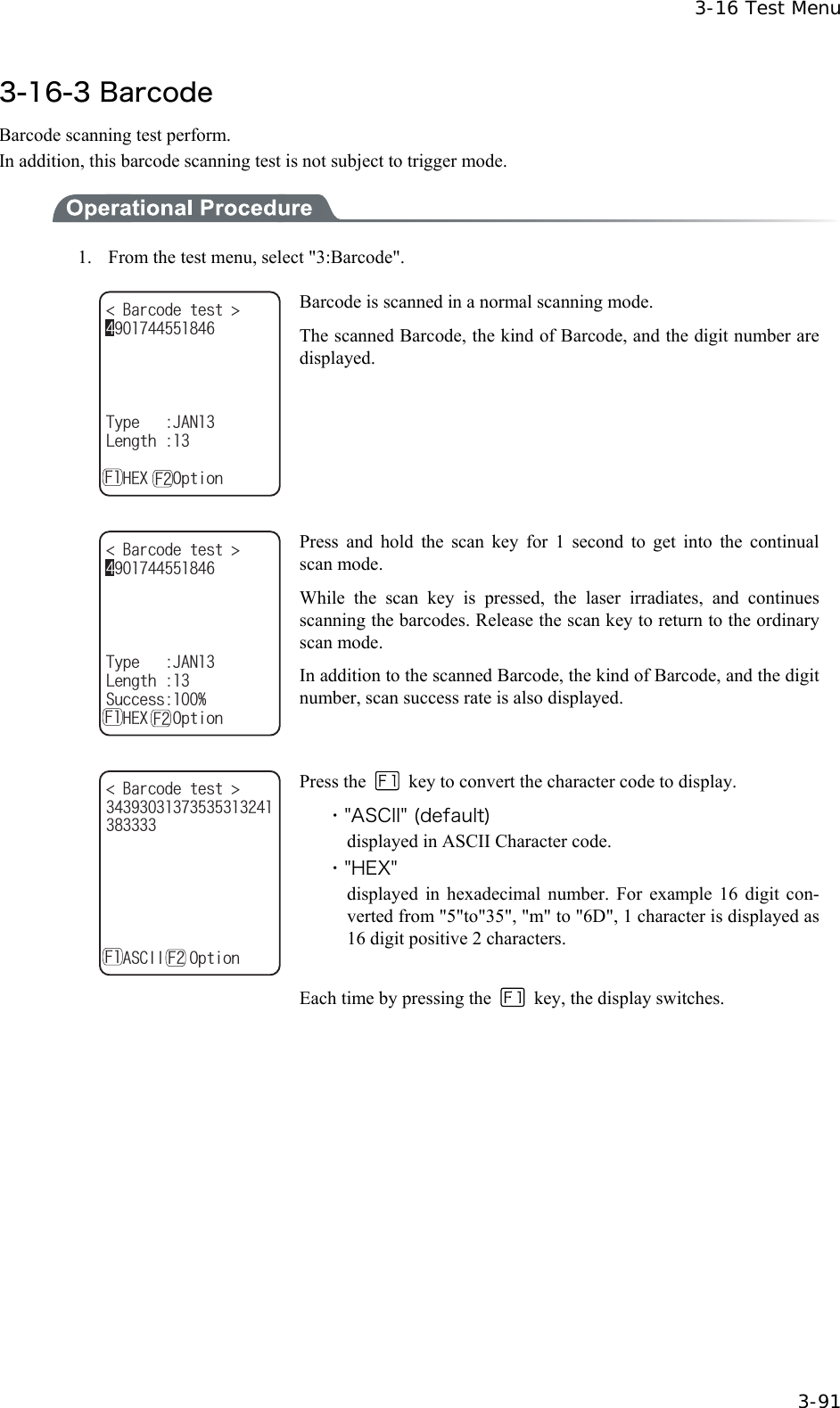
![Chapter 3 System menu 3-92 ■Barcode Option %JGEMFKIKV$CTEQFGQRVKQP 455,#0'#072% Press the key to allow setting varieties of barcode options. In addition, this setup only enabled during the barcode testing. ●Check digit Setup whether to check the check digit. ・ [Check Enable] is set to OFF (default) The check of check digit is disabled. ・ [Check Enable] is set to ON The check of check digit is enabled. ●JAN/EAN/UPC Setup the scanning condition of add-on code of JAN/EAN/UPC. ・ Ignore Add-on (default) Add-on code scanning disabled. ・ Read all Both can be scanned unconditional whether add-on code is added. ・ Read Add-on only JAN/EAN/UPC with add-on code only can be scanned. ●RSS Setup the scanning condition of RSS Stacked. ・ Prohibition (default) RSS stacked scanning is disabled. ・ Permission Scanning RSS Stacked is enabled.](https://usermanual.wiki/Welcat/GTX100/User-Guide-859113-Page-147.png)