Welcat GTX100 Handy Terminal User Manual 7th M01GTX100
Welcat, Inc. Handy Terminal 7th M01GTX100
Welcat >
user manual

GTX-100
Õóåò§óÍáîõáì
ÇÔر°°
×éòåìåóóÈáîäùÔåòíéîáì
Èáòä÷áòå¯ÓùóôåíÍåîõ

i
China Regulations
This product is based on a Chinese SRRC rule.
1.Do not change frequency without permission, and increase the transmission
of a message output.(include the installation of a high frequency amplifier out
of a rule)
2.For the Occupied, do not give the interference that is harmful to the other legal
radio broadcasting stations.
When harmful interference occurred, stop use promptly, and reopen after
removing interference.
3.When using low power wireless telegraphy facilities, bear the interference
from the other legal radio broadcasting stations, or interfered with industry,
science, radiation of medical facilities.
4.Do not use it in the vicinity of an airport and an airport.

ii
Trademarks
-Microsoft, Windows, and Visual Basic are the U.S. Microsoft Corporation's registered trade-
marks or the trademarks in the U.S. or other countries.
-Bluetooth is the registered trademark of Bluetooth SIG, Inc. and Welcat, Inc is using it based on
the license.
-The program "UBQ-WLAN" developed by Canon i-tech,Inc. is equipped in this product.
"UBQ-WLAN" is the trademark of Canon i-tech,Inc.
-The decoder of MPEG Layer-3 audio is equipped in this product.
-The decoding technology of MP3 is used based on the license from Fraunhofer IIS and
Thomson.
-The bit-mapped font developed by Ricoh Company,Ltd. is equipped in this product.
-The copyrights of pictures, sound and tools included in each manual and each materials col-
lection belong to Welcat, Inc.
-The pictures, sound and tools included in each manual and each materials collection cannot use
and reproduce any part or all of them without the express consent of Welcat, Inc.
-The products and corporate names which are described in addition are the registered marks or
brand of each enterprise.
iii
SAFETY PRECAUTIONS
・ Be sure to read these precautions before using this product in order to insure safe operation of
the equipment.
・ Keep this User's Manual on hand for future reference whenever you may need it.
Strict observance of these warning and caution indications are MUST for preventing accidents
which could result in bodily injury and substantial property damage. Make sure you fully un-
derstand all definitions of these terms and related symbols given below, before you proceed to
the text itself.
Danger
This symbol indicates an item that can result in death or serious personal injury if ignored and
emergency of warning when dangerously generated is high.
Warning
This symbol indicates an item that can result in death or serious personal injury if ignored.
Caution
This symbol indicates an item that can result in serious personal injury or material damage if
ignored.
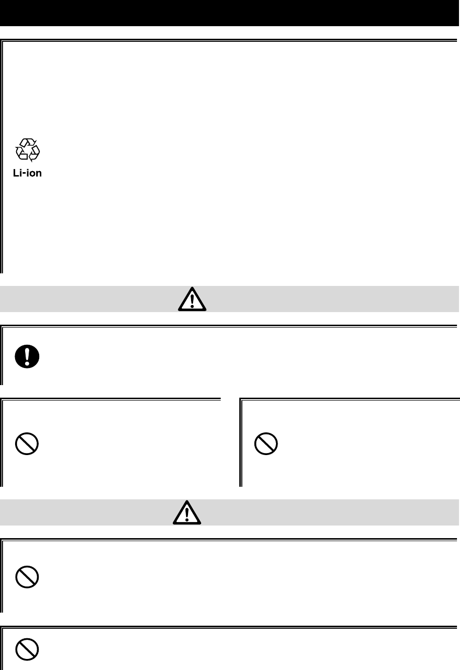
Meaning of Symbols
A diagonal line through a circle indicates something you should
not do
A black circle indicates something you must do.
A triangle inside indicates something you should be careful about.
iv
Observe strictly
Observe the display of the danger that the manufacturer of the personal com-
puter and peripherals used is directing and warning and attention strictly when
you use the product.
About GTX-100, Battery pack(GTB-1)
Danger
Only use the specified our
peripherals.
Peripherals for GTX-100:
- Battery pack
(GTB-1)
- Single charger
(GTC-1) option
- Multi charger
(GTC-2) option
Do not place or use the
products in the hot places
such as a fire side, a stove
side, under the burning sun,
etc.
Doing so could cause battery
–rupture or leakage of battery
fluid and resulting in a fire, burn,
bodily injury, or serious damage
to property.
Do not place products in a
microwave oven and a
high-pressure container, etc.
Doing so could cause battery
–rupture or leakage of battery
fluid and resulting in a fire, burn,
bodily injury, or serious damage
to property.
Do not heat products, nor
put into fire .
Doing so could cause battery
–rupture or leakage of battery
fluid and resulting in a fire, burn,
bodily injury, or serious damage
to property.
Do not stare into laser beam.
Do not aim the laser at a
person’s eye.
The laser beam emitted through
the reading window is harmful to
the eyes.
v
Warning
Stop the charge, when the
charge is not completed,
even if it exceeds prede-
termined charge time.
Doing so could cause battery
–rupture or leakage of battery
fluid and resulting in a fire, burn,
bodily injury, or serious damage
to property.
Do not place or use prod-
ucts in high humid or dusty
areas.
Doing so could cause battery
–rupture or leakage of battery
fluid and resulting in a fire, burn,
bodily injury, or serious damage
to property.
When heating, smoking, a
nasty smell, etc. occur, turn
off the power supply and
remove the battery.
When it continues using it, it will
become the cause of generation
of heat and firing.
In a battery cartridge, it also
becomes the cause of a liquid
spill and a burst further.
Do not attempt disassemble
or modify products.
Doing so could cause battery
–rupture or leakage of battery
fluid and resulting in a fire, burn,
bodily injury, or serious damage
to property.
Prevent from touching a
part of
y
our bod
y
, such as a
hand and a finger to the
terminals of a battery, the
battery contacts / charge
contacts of a main body,
and the external aerial
connection terminal.
It may become the cause of an
electric shock, injury, failure,
and malfunction.
Do not bring close to
chemicals.
Do not use and keep it near
chemicals or in the place
which chemicals touch.
It becomes accidents, such as an
electric shock and a fire, or the
cause of failure.
Do not short-circuit or sol-
der neither the battery ter-
minals, nor the battery
contacts / charge contacts
of a main body.
Doing so could cause battery
–rupture or leakage of battery
fluid and resulting in a fire, burn,
bodily injury, or serious damage
to property.
Do not connect reversely
the positive and negative
polarity terminals of a bat-
tery, and do not charge it in
that condition.
Doing so could cause battery
–rupture or leakage of battery
fluid and resulting in a fire, burn,
bodily injury, or serious damage
to property.
vi
Caution
Do not place or charge the batter
y
in the hot places such as a fire side,
a stove side, under the burning sun, etc.
Doing so could cause battery –rupture or leakage of battery fluid and resulting in
a fire, burn, bodily injury, or serious damage to property.
Do not put it in an unstable
place.
Apparatus drops or falls down
and it causes an injury and a
failure of the apparatus.
Do not put it in the place
which an infant's hand
reaches.
It becomes cause, such as an
injury.
This product is not developed, not intended, not permitted to use this
product for the equipment, (atomic energy control, aircraft flight
control, air traffic control, mass transport control, life support s
y
stem,
and weapon control s
y
stems, hereinafter "High Safet
y
Required Use"),
whose failure could threaten directly human life or affect human body.
Welcat, Inc assumes no liability whatsoever for damages arising from use of this
product by the user in concerned High Safety Required Use applications.

vii
About GTX-100
Warning
Be careful not to hook a
strap when carrying the
terminal.
If strap is caught in an obstacle,
it could cause injury or accident.
Do not use this product near
the electric device which
processes highly precise
control and a weak signal.
It may influence electric devices
(such as medical treatment
electric device, fire alarm,
automatic door, other automatic
control apparatus, etc.) to gen-
erate malfunction etc.
Do not put a foreign substance into the inside of a main body.
When a foreign substance or a liquid go into the inside of the main
body, stop use, and inform the store of purchase.
When it is then used, it will become accidents, such as an electric shock and a
fire, or the cause of failure.
Caution
Use it detaching as far as
possible from the apparatus
which emits noise, such as a
computer, a fluorescent
light and a microwave oven.
There is a case where it be-
comes impossible to commu-
nicate normally under the in-
fluence of the noise.
Be sure to hold it in your
hand and operate it.
When you operate it in the
condition to put it on a charger
or on a floor or on a desk, it will
become failure of the apparatus
or the cause of malfunction.
Do not give the high impact.
Do not drop, do not throw out,
and do not beat the main body.
It becomes malfunction of the
main body, and the cause of
failure.
Do not put in in water, and
sprinkle water by strong
power.
If water will gets into the ter-
minal, resulting in failure, fire or
electrical shock.
Do not use and keep it in a place with a possibility that the strong
magnetic fields near a magnet, a speaker, and the cathode-ray tube
etc. may occur.
It becomes malfunction of the main body, and the cause of failure.
viii
About Battery pack(GTB-1)
About used battery pack(GTB-1)
The rechargeable lithium-ion battery (Battery pack GTB-1) is used for
the GTX-100
A rechargeable lithium-ion battery is a small secondary battery with
which a duty of recovery and recycling is imposed on the apparatus
maker who uses the batteries and on the battery maker by the "Law
for Promotion of Effective Utilization of Resources".
Our company performs the recovery and the recycling of used small
secondary batteries as a member of the limited liability middle cor-
poration JBRC (Japan Portable Rechargeable Battery Recycling
Center).
Do not throw away the used battery which is worn-out together with common
garbage.Please inform our company and ask about the recovery.
Danger
If battery fluid gets in your eyes, wash it out with clean water and
contact a physician immediately.
If it is left, there is fear of loss of eyesight.
Do not heat the battery
pack, nor put into fire
Doing so could cause the bat-
teries to break, generate heat,
rupture or burn.
Do not put the battery pack
to water and seawater, etc.
Doing so could cause the bat-
teries to break, generate heat,
rupture or burn.
Warning
Do not use the battery if leakage, change of color or shape, or other
abnormalities occur.
Doing so could cause fire, burn, bodily injury, or serious damage to property. If
it brings close to fire, this cause ignition in leakage of battery fluid.
Do not stick a nail, do not strike with a hammer, or do not trample.
Doing so could cause the batteries to break, generate heat, rupture or burn.

ix
Laser safety standard
This product is based on the safety-standards (JIS C 6802) class 2 of a laser product.
Maximum output: 1mW
Wavelength: 650±10nm
Although, in the class 2, eyes are protected by the dislike-reaction, such as blink, do not look into the
laser light or do not put directly the laser light into your eye.
Do not perform the use which is not in accordance with the user's
manual, and do not disassemble the product.
It may cause exposure to dangerous laser radiation.
LCD
Although a small difference is sometimes in a backlight color or brightness between products, this is
the dispersion by the property of liquid crystal, and is not defective product.
Laser Safety
This product using the laser comply with US 21CFR1040.10.
This equipment is certified as a Class 2 laser product under the U.S. Department of Health and Human
Services (DHHS) Radiation Performance Standard according to the Radiation Control for Health and
Safety Act of 1968. This means that the equipment does not produce hazardous laser radiation.
FDA Regulations
U.S. Food and Drug Administration (FDA) has implemented regulations for laser products manufac-
tured on and after August 2, 1976. Compliance is mandatory for products marketed in the United
States. The labels on the product indicate compliance with the FDA regulations and must be attached
to laser products marketed in the United States.
Caution:
Do not look into the laser beam source through the reading window or point the read-
ing window towards the eyes. The laser beam emitted through the reading window is
harmful to the eyes.
Use of controls, adjustments or performance of procedures other than those specified
in this manual may result in hazardous invisible radiation exposure.
Class 2 laser scanners use a low power, visible light diode. As with any very bright
light source, such as the sun, the user should avoid staring directly into the light beam.
Momentary exposure to a Class 2 laser is not known to be harmful.
x
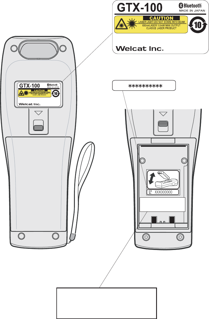
Laser warning labels
(INSIDE)
GTX-100
Labels
Product Label
SER
No.
Serial Label
FDA Label
This product complies with 21 CFR 1040.10.
MANUFACTURED:OCT.2007 Welcat Inc.
4-12-8 Higashi-Shinagawa,
Shinagawa-Seaside East tower 6F
Shinagawa-Ku, Tokyo 140-0002 Japan
This product complies with 21 CFR 1040.10.
MANUFACTURED:OCT.2007 Welcat Inc.
4-12-8 Higashi-Shinagawa,
Shinagawa-Seaside East tower 6F
Shinagawa-Ku, Tokyo 140-0002 Japan
CMII ID:XXXXXXXXXX
FCC ID:Q98GTX100
CMII ID:XXXXXXXXXX
FCC ID:XXXXXXXXXXXX

xi
US Regulations
This device complies with Part 15 of the FCC Rules. Operation is
subject to the following two conditions:
(1) this device may not cause harmful interference, and
(2) this device must accept any interference received, including
interference that may cause undesired operation.
Note:
This equipment has been tested and found to comply with the limits for a Class
B digital device, pursuant to Part 15 of the FCC Rules. These limits are de-
signed to provide reasonable protection against harmful interference in a
residential installation. This equipment generates, uses and can radiate radio
frequency energy and, if not installed and used in accordance with the
instructions, may cause harmful interference to radio communications.
However, there is no guarantee that interference will not occur in a particular
installation.
If this equipment does cause harmful interference to radio or television re-
ception, which can be determined by turning the equipment off and on, the
user is encouraged to try to correct the interference by one or more of the
following measures:
-- Reorient or relocate the receiving antenna.
-- Increase the separation between the equipment and receiver.
-- Connect the equipment into an outlet on a circuit different from that
to which the receiver is connected.
-- Consult the dealer or an experienced radio/TV technician for help.
Warning:
You are cautioned that changes or modifications not expressly approved by
the party responsible for compliance could void your authority to operate the
equipment.
FCC Radiation Exposure Statement
This equipment complies with FCC radiation exposure limits set forth for an uncontrolled en-
vironment. End-users must follow the specific operating instructions for satisfying RF exposure
compliance.
This transmitter must not be co-located or operating in conjunction with any other antenna or
transmitter.
The GTX-100 has been tested and found to comply with the Federal Communications Com-
mission (FCC) guidelines on radilo frequency energy (RF) exposures.
The maximum SAR levels tested for the GTX-100 has been shown to be x.xxx W/kg (1gram
average) at body.
0.344

xii
Caution about radio wave.
Please stop using this product in the following conditions. Moreover, be sure to
read the(P.iii)of " SAFETY PRECAUTIONS " before use.
・ Do not use this product near the person wearing a cardiac pacemaker, or
near the medical equipment using. It causes electromagnetic interference to
medical equipment. There is danger of human life.
・ Do not use this product near microwave oven. Interference occurs in the
radio communications of this product by the radio wave which leaks from
the microwave oven.
In the operating frequency band of this apparatus, industry of microwave oven
etc., science, equipment for medical treatments, the premises radio station
(radio station which requires the license) for movable body identification used
in the manufacture line of a factory etc., and a specified low power radio sta-
tion (radio station which does not require the license) are also operating.
1. Confirm that the premises radio station and specified low power radio sta-
tion for movable body identification are not operated near the place before
using this apparatus.
2. When the radio wave interference occurs at the premises radio station for
movable body identification system from this apparatus ,change operating
frequency promptly or stop emission of radio wave, after that action, please
inform our sales department, and please consult about disposal for inter-
ference avoidance etc. (for example, installation of a partition) etc.
3. In addition, when the instance of radio wave interference occurs at the
specified low power radio station for movable body identification etc. from
this apparatus, or when what is troubled by something occurs, please in-
quire with our sales department.
The feature of the WLAN communication is as follows.
Operating frequency band bandwidth 2.4GHz
Band modulation method DS-SS OFDM
Assumption interference dis-
tance
40m or less
Propriety of frequency change It means that it can avoid the operating
frequency band of movable body iden-
tification apparatus by using all band-
width.
The feature of the Bluetooth communication is as follows.
Operating frequency band bandwidth 2.4GHz
Band modulation method FH-SS
Assumption interference dis-
tance
10m or less
Propriety of frequency change It uses all bandwidth and avoidance of
xiii
the operating frequency band of mov-
able body identification apparatus is
impossible.
1. This equipment contains the radio apparatus which received the Technical
Regulations Conformity Certification based on the Radio Law.
2. Disassembly or touching the inside of this apparatus is prohibited by the
Radio Law, and it may be punished with the law. In the case of failure, please
entrust check and adjustment of the inside to the store of purchase.
3. This apparatus can be used only in Japan. Since radio wave standards differ
overseas, it cannot be used.

xiv
Caution about security at the time of wireless LAN product op-
eration
< Important matter about customer's right (privacy protection)! >
Because exchanging information between personal computers etc. via radio ac-
cess points in wireless LAN which uses a radio wave instead of using LAN ca-
bles, the wireless LAN has an advantage that in case it is inside the range the
radio wave can reach, LAN connection is freely possible.
On the other hand, because the radio wave can reach to all places through
obstacles (wall etc.) , within a certain range, when a setup about security is
omitted, the following problems may occur.
● The contents of communication may try to be stolen.
A malicious third person intercepts radio wave intentionally.
- Personal information such as ID, password or credit card number
- The contents of e-mail
Etc. may be tried to steal.
● To be invaded unjustly.
A malicious third person accesses without permission to the network of an
individual or company.
- To pick up personal information and confidential information (leak of
information)
- To personate a specific person, and communicates, and send unjust
information (spoofing)
- To rewrite and send the intercepted contents of communication (al-
terations)
- To send computer virus etc. and destroy data and system (destruction)
Etc. action may be done.
Because the wireless LAN terminal, the wireless LAN card, and the radio access
points originally have the method of security for dealing with these problems,
when you use a wireless LAN product, executing the setup about security can
reduce a possibility that these problems will occur.
Immediately after purchase, the condition is that the setup about security of the
wireless LAN equipment may not be performed.
Therefore, by the customer, in order to reduce a possibility of the generating se-
curity problem, before using the wireless LAN terminal, wireless LAN card, and
wireless LAN access point, be sure to execute all setup about security of wireless
LAN equipment according to a manual.
In addition, on the specification of wireless LAN, because security setup may be
broken by a special method, please use it after understanding.
About a setup of security etc., when you cannot deal with it by the customer
side, please inquire with our sales department.
Our company recommends you to understand enough the occurring problem
when using the product without a customer side security setup, then perform
security setup in your judgment and responsibility, and use the product.
Our company cannot take the responsibility to what kind of trouble (damage)
generated without the customer side security setup in your judgment and re-
sponsibility.

xv
Refer to the following about security setup of this product.
① SSID Setup (P.3-22)
② Security Setup(P.3-24)
③ MAC address(P.3-34)
used when using the MAC Address filtering function of a wireless LAN
access point.

xvi
Contents
SAFETY PRECAUTIONS....................................................................................................... iii
Laser safety standard............................................................................................................. ix
LCD ............................................................................................................................................ ix
Laser Safety.............................................................................................................................. ix
FDA Regulations ..................................................................................................................... ix
Laser warning labels................................................................................................................x
Caution about radio wave................................................................................................... xii
Contents.................................................................................................................................. xvi
Introduction ........................................................................................................................... xix
Enclosed items ...................................................................................................................... xix
Optional Extras ..................................................................................................................... xix
Notational Information.........................................................................................................xx
Manual Contents................................................................................................................... xxi
1 Hardware 1-1
1-1 Part Names...............................................................................................................................................................1-2
1-2 Preparation before Use..............................................................................................................................1-4
1-2-1 Equipment Connections ..........................................................................................1-4
1-2-2 Additional Software ..................................................................................................1-5
1-3 Wireless Communications........................................................................................................................1-6
1-3-1 Preparations for Data Communication................................................................1-7
1-3-2 Data-Communication Method ...............................................................................1-8
1-4 Product Specifications............................................................................................................................ 1-10
1-5 Scanning Specifications......................................................................................................................... 1-14
1-6 Charging Specification............................................................................................................................ 1-17
1-6-1 Charging the Battery Pack................................................................................... 1-17
1-6-2 Charging Method using Single Charger (GTC-1) ........................................... 1-17
1-6-3 Charging Method using Multi Charger (GTC-2)............................................. 1-19
1-7 Battery pack (GTB-1)................................................................................................................................ 1-21
1-7-1 Charging the Battery Pack................................................................................... 1-21
1-7-2 Installing and Removing a Battery .................................................................... 1-21
1-7-3 Replacing the Worn out Battery Pack .............................................................. 1-22
1-7-4 Cautions about Cleaning of Electrodes ............................................................ 1-22
1-7-5 Charging the Backup Battery.............................................................................. 1-22
1-8 Memory Backup Period (Battery for backup)............................................................... 1-23
1-9 Not use in long time................................................................................................................................... 1-25
1-10 Resume function ........................................................................................................................................ 1-26
1-11 Screen Output Characters.............................................................................................................. 1-27
2 Software 2-1
2-1 GTX-100 Software ...........................................................................................................................................2-2
2-1-1 Data Storage ...............................................................................................................2-2
2-2 System menu .........................................................................................................................................................2-4
3 System menu 3-1

xvii
3-1 Introduction..............................................................................................................................................................3-2
3-2 Save the System Parameter..................................................................................................................3-2
3-2-1 Registry ........................................................................................................................3-2
3-3 Key Names and Functions.......................................................................................................................3-3
3-4 System Menu Operations.........................................................................................................................3-5
3-5 Battery Level...........................................................................................................................................................3-8
3-6 Starting the System Menu......................................................................................................................3-9
3-6-1 How to Start the System menu..............................................................................3-9
3-6-2 Executing a DHCP Request ....................................................................................3-9
3-6-3 Starting State for Wireless LAN Operation ........................................................3-9
3-6-4 Executing Setup Wizard ....................................................................................... 3-10
3-6-5 WLAN Security Alert............................................................................................. 3-12
3-7 System Menu List ......................................................................................................................................... 3-13
3-8 System Setup Menu................................................................................................................................... 3-15
3-8-1 Setting the programs for Automatic Launch................................................... 3-15
3-8-2 Clock ......................................................................................................................... 3-16
3-8-3 Resume (resume function) ................................................................................... 3-17
3-8-4 Password .................................................................................................................. 3-18
3-8-5 Auto wake up.......................................................................................................... 3-20
3-8-6 Auto power off........................................................................................................ 3-21
3-9 WLAN Menu ........................................................................................................................................................ 3-22
3-9-1 SSID ........................................................................................................................... 3-22
3-9-2 Roaming level ......................................................................................................... 3-23
3-9-3 Doze mode............................................................................................................... 3-23
3-9-4 Security..................................................................................................................... 3-24
3-9-5 Advanced .................................................................................................................3-32
3-9-6 MAC address ........................................................................................................... 3-34
3-10 Network Menu............................................................................................................................................... 3-35
3-10-1 TCP/IP .................................................................................................................... 3-35
3-10-2 DHCP ...................................................................................................................... 3-36
3-10-3 FTP .......................................................................................................................... 3-38
3-10-4 DNS ......................................................................................................................... 3-41
3-10-5 SNMP...................................................................................................................... 3-42
3-11 Receiving Menu ............................................................................................................................ 3-46
3-12 File Menu............................................................................................................................................................. 3-49
3-13 ID Menu................................................................................................................................................................. 3-57
3-14 Device Menu.................................................................................................................................................... 3-58
3-14-1 Barcode .................................................................................................................. 3-58
3-14-2 Key .......................................................................................................................... 3-63
3-14-3 Bluetooth ................................................................................................... 3-63
3-14-4 Display ....................................................................................................... 3-70
3-14-5 Tone/Vibrator .......................................................................................... 3-71
3-15 Manage Menu................................................................................................................................................ 3-77
3-15-1 Battery level .......................................................................................................... 3-77
3-15-2 System versions.................................................................................................... 3-78

xviii
3-15-3 Initialize ....................................................................................................... 3-78
3-15-4 Clone .......................................................................................................... 3-80
3-15-5 Drive ........................................................................................................... 3-83
3-15-6 Mothball................................................................................................................. 3-84
3-15-7 Wizard .................................................................................................................... 3-85
3-16 Test Menu.......................................................................................................................................................... 3-86
3-16-1 WLAN..................................................................................................................... 3-86
3-16-2 Bluetooth................................................................................................................ 3-90
3-16-3 Barcode .................................................................................................................. 3-91
3-16-4 Display.................................................................................................................... 3-93
3-16-5 Key .......................................................................................................................... 3-94
4 FAQ (Frequently Asked Questions) 4-1
4-1 FAQ ...................................................................................................................................................................................4-2
Q: The power does not turn ON.......................................................................................4-2
Q: Nothing is displayed on the screen............................................................................4-2
Q: After not using for a while, the power is shut OFF. ..............................................4-2
Q: It cannot charge. .............................................................................................................4-2
Q: The System Menu does not start. ...............................................................................4-3
Q: How do I change the application, which starts when the power is turned ON?4-3
Q: How do I start another application? .........................................................................4-3
Q: The Barcode is not scanned successfully. ................................................................4-3
Q: How do I check the free area of a drive?................................................................4-3
Q: I cannot perform wireless data communications. ..................................................4-4
Q: I cannot perform Bluetooth communication. ..........................................................4-4
Q: Can I use at the same time both WLAN and Bluetooth in the same environment
and on the same terminal?................................................................................................4-5
Q: "Writing Failed" was displayed during transmission or reception of a file. .....4-5
Q: "Time Out" was displayed during transmission or reception of a file. ..............4-5
Q: "Connection Failed" was displayed during transmission or reception of a file.4-5
Q: I want to perform the setup of the terminal IP address etc. at a time from a
computer.................................................................................................................................4-6
Q: Starting an application or transmission/reception of a file cannot be performed.
..................................................................................................................................................4-6
Q: I suspect that the file is corrupt. .................................................................................4-6
Q: "System Error" was displayed and after pressing a key, the power turned OFF.4-6
5 System Menu Factory Settings List 1
Appendix. A-1 System menu Factory Settings..................................................................................2
6 Sample Barcode 1
Appendix. B-1 Sample Barcode..........................................................................................................................2
7 Index 1
Index..................................................................................................................................................................................................2
xix
Introduction
Thank you very much for purchasing our wireless handy “GTX-100.”
This user manual explains the hardware and the system program of the GTX-100.
We hope the GTX-100 will help you improve efficiency of your business.
Enclosed items
・ GTX-100 ........................................................................................ 1
・ Battery pack(GTB-1) ..................................................................... 1
・ Hand Strap...................................................................................... 1
・ Manual CD-ROM(GID-009).......................................................... *
* Attached in exclusive package.
Optional Extras
・ Dust protection cover(DC-001)
・ Anti-shock cover(DC-002)
・ Access point(our recomended equipment)
・ Single Charger(GTC-1)
・ Multi Charger(GTC-2)
・ BluePorter(WLF-001) - Bluetooth file transferring utility.
・ WebGlider-X(WBG-001W) - Integrated middleware package for web applications.
・ Handy 5250(HTN-5250A) - 5250 Emulator for handy terminals.

xx
Notational Information
Indicates a note you can refer to.
Indicates a caution.
"GTX-100" "Terminal" Wireless LAN Terminal, Wireless Hand-held Terminal GTX-100.
Access point
The wireless communication interface to allow data to be sent between
the GTX-100 and a PC connected to an Ethernet communicating via
TCP/IP. Please use our recommended equipment based on the
IEEE802.11b/g WLAN standard.
WLAN Wireless LAN
System Program The OS stored in the GTX-100.
System Menu A function of the system program.
WebGlider-X browser The browser operates as an application of the terminal when web based
system is configured by using "WebGlider-X".
WebGlider-X "WebGlider-X" is an integrated middleware package for web applica-
tions (WBG-001W). Please purchase separately if needed.
BluePorter
Utility software for executing file Transfer using Bluetooth communi-
cation between the PC and the terminal. Please purchase separately if
needed.
F Drive
The storage area for storing application, database, and master files. etc.
The application data downloaded from the host computer will be stored
in F drive.
S Drive Used for the storage area to store a temporary file during the applica-
tion is running.
Battery pack "GTB-1"
Backup battery The battery to perform a temporary saving the built in clock data and
files when the battery pack is removed or the power becomes short.
Scan key Used when scanning a barcode.
Local device Bluetooth device during operation is running. When the GTX-100 is in
operation, "Local device" means the GTX-100.
Remote device Bluetooth device to which the local device is connected.
Default device
The Bluetooth device setup as default among the registered Remote
device list in the System Menu. In the System Menu always this default
device is connected to.
xxi
Manual Contents
●Chapter 1 Hardware
Explains the standard handling, specifications and operation methods of the GTX-100.
●Chapter 2 Software
Explains an outline of the software installed, and related to the GTX-100.
●Chapter 3 System menu
Explains the System Menu setup and Operation Method.
●Chapter 4 FAQ (Frequently Asked Questions)
Questions and troubles frequently asked, and the items required for resolving them, refer-
ence pages of this manual are also commented.
●Appendix. A System Menu Factory Settings List
●Appendix. B Sample Barcode
●Index

Chapter 1
1 Hardware
Chapter 1 Hardware
1-2
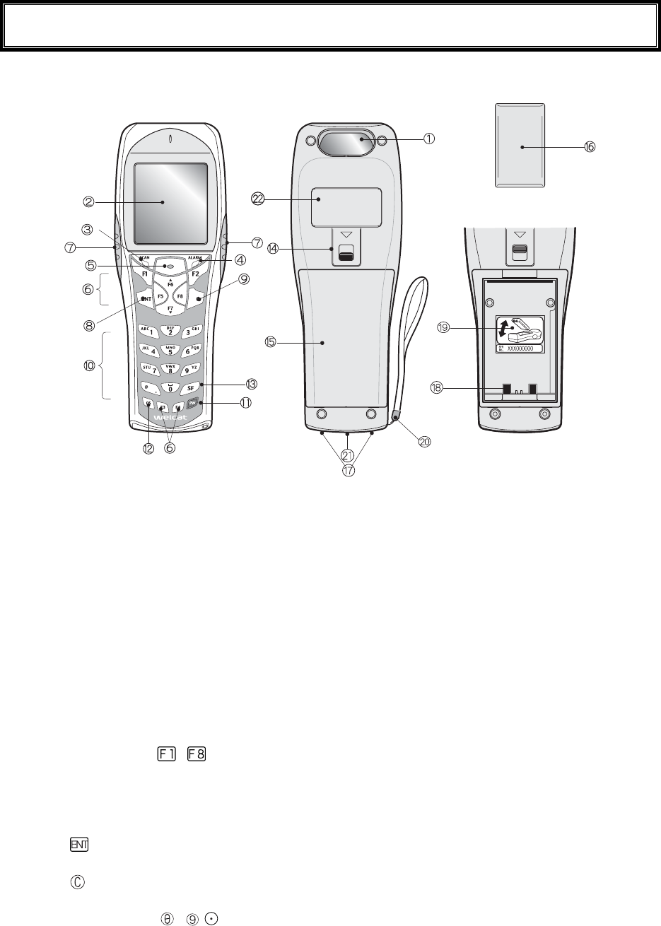
1-1 Part Names
1. Barcode window
The opening from where the Barcode is read. As the laser light is irradiated, be sure NOT to look into
the window.
2. LCD (Liquid Crystal Display)
Data, characters and images are displayed on the LCD.
3. SCAN LED (LED Indicator)
If a barcode is read correctly, the light will turn green.
While the battery is being charged, the light will turn ON red. When the battery charging is completed,
it will turn ON green.
4. ALARM LED
Shows the status of Wireless Communications. Shows the status of wireless communications with the
access point and the status of EAP authentication processing (P.1-13).
5. Scan Key
Press this key to read a Barcode.
6. Function Keys( to )
Used for changing functions and cursor operation.
7. F9 key, F10 key
Used for changing functions and cursor operation. Leftward by F9 key, Rightward by F10 key, when
using this key to scan a barcode, support by the software is required.
8.
key (Enter Key)
Press this key to confirm and to execute the entered data or operation.
9. key (Cancellation Key)
Used to return to the previous screen, or deleted all the characters entered.
10. Numeric Keys (
to ,)
Used to input assigned numeric, characters, or, select the corresponding item in the Menu.

1-1 Part Names
1-3
11. key (Power Switch)
12. key (back space key)
Deletes the last character entered.
13. key (Shift key).
Used to switch to the character input mode, or special functions can be accessed by pressing this key
together with other keys.
14. Battery Cover Lock Lever
Move the lever to the direction of an arrow to lock. Be sure to keep it locked when using it.
15. Battery Cover
Always attach the battery cover while in use.
16. Battery Pack
After purchasing, be sure to charge the battery pack before you use. Be careful not to have the Charg-
ing terminal jack attached with dust or dirt. When dust or dirt is attached, remove it with a swab etc.
17. Charging jack
Be careful not to have the Charging terminal jack attached with dust or dirt. When dust or dirt is at-
tached, remove it with a swab etc.
18. Battery electrode
Be careful not to have the Battery electrode attached with dust or dirt. When dust or dirt is attached,
remove it with a swab etc.
19. Serial number seal
The seal is attached that carries serial number and a description about the direction to which re-
move/install the battery pack.
20. Hand Strap
21. Speaker Hole
22. Product plate
Product name, manufacturer and the laser alarm etc. are described.
23. Laser warning sticker
A warning associated with the use of laser beams is printed on this sticker.
Chapter 1 Hardware
1-4
1-2 Preparation before Use
Please carry out following preparations before using the GTX-100
● Battery Pack GTB-1
The battery pack is required in order to use the GTX-100. The battery pack should be charged before
use, attached correctly and locked with the battery cover.
● Isn't the barcode window dirty?
If the barcode window is dirty, a barcode cannot be scanned correctly. When dirty, please wipe lightly
with a soft cloth etc.
● Isn't charging terminal dirty?
If the charging terminal is covered with dust or dirt, charging error or failure may occur. When dirty,
please remove the dust or dirt by using a swab etc.
1-2-1 Equipment Connections
Data entered can be transmitted from the GTX-100 to a host computer or the GTX-100 can receive data from a
host computer.
The following are the Methods for connecting to a host computer. Preparations required depend on the applica-
tion environment.
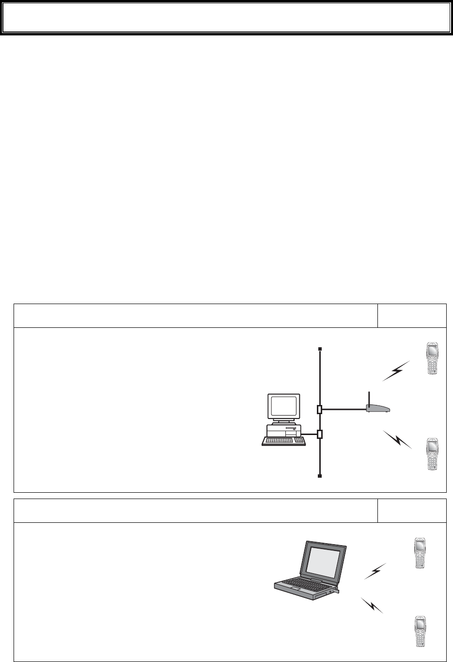
In the case of WLAN communication P.1-8
The GTX-100 communicates via wireless LAN communi-
cation to a host computer through an access point, which is
connected to the Ethernet LAN.
■Purchased Separately
Access Point (our recommended product)
Ethernet cables, HUB
For details about setting up a wireless network, refer to the
Access point Manual and the document.
In the case of Bluetooth communication P.1-9
The GTX-100 communicates via Bluetooth communication
to a host computer through USB adapter, which is con-
nected to the USB port of the host computer.
■Purchased Separately
Transfer Utility "BluePorter" (Bluetooth USB adapter is in-
cluded.)
Computer

1-2 Preparation before Use
1-5
1-2-2 Additional Software
In the case where you want to create a system for data communication between the GTX-100 and a host com-
puter or build a system using theGTX-100 browser, the following software is required.
For details of the System configuration, please refer to the online Manual attached to respective software.
Software name Preparation/Use
Web based inte-
grated middleware
package
WebGlider-X
The WebGlider-X software is required when building a Web based wireless
system using the WebGlider-X Browser.
Please install the "WebGlider-X" package on a computer and setup the com-
munication environment, before performing data communication between the
computer and the "WebGlider-X" browser.
5250 Emulator for
handy terminal
Handy5250
The Handy 5250 software is required when creating a system to connect to an
AS/400 host via the 5250 emulation environment. Please purchase separately
if needed.
Before using, install the Handy 5250 setup utility, which will allow the setup
of the communication environment.
Transfer utility
Blue Porter
The Blue Porter is utility software to perform File Transfer for Bluetooth
communication. Please purchase separately if needed.
Before using, installing the driver software and the Bluetooth USB adapter
setups are required.
Chapter 1 Hardware
1-6
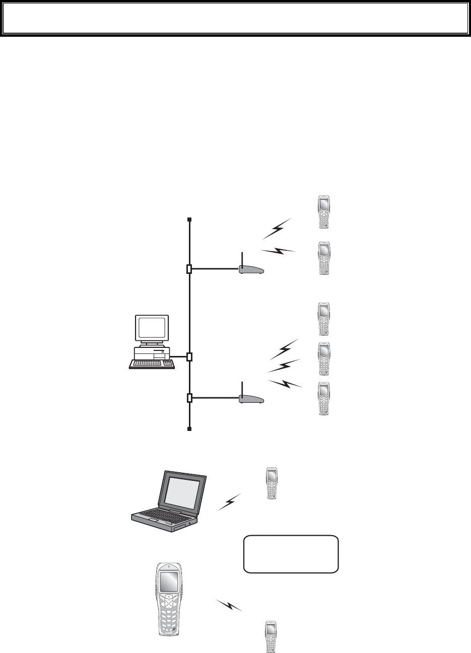
1-3 Wireless Communications
■Wireless function of the GTX-100
The GTX-100 is a handy terminal network system incorporating a wireless communication system. The Barcode
terminal is small, lightweight and excels in portability. It is also suitable for moving around the work place, op-
erating remotely from the computer while collecting Barcode data.
The GTX-100 's wireless communication system is based on WLAN and Bluetooth methods. WLAN conforms
to the WLAN standard, IEEE802.11b/g. The maximum possible wireless transmission speed is approximately
54Mbps, enabling the indoor wireless communication up to 75m distance. Bluetooth conforms to the Bluetooth
Specification ver1.2, enabling up to 10m communications. Transmission and reception of scanned Barcode data
or files can be performed in real time through the wireless network.
±°¯±°°
ÂÁÓÅÔ
±°¯±°°
ÂÁÓÅÔ
ᴥÉÅÅŸ°²®±±â¯çᴦ
ᴥÉÅÅŸ°²®±±â¯çᴦ
ÇÔر°
°
ÇÔر°
°
×éòåìåóóÎåô÷ïòë
ÁããåóóÐïéîô
×éòåìåóóÎåô÷ïòë
ÁããåóóÐïéîô
Ãïíðõôåò
Network example (WLAN communication)
Éôãáîáìóïãïííõîé
ãáôå÷éôèáîïðôéïîáì
ðòéîôåò®
Computer
GTX-100
Network example (Bluetooth communication)
1-3 Wireless Communications
1-7
■WLAN Communications
The wireless communication system is based on the IEEE802.11b/g standard, which is generally used
in Wireless Local Area Networks (WLAN). In almost all cases, wireless communication can be per-
formed if the access point used is based on the IEEE802.11b/g standard, however, please use our
recommended product to perform a stable communication.
As for this product, only the infrastructure mode is supported. It does
not support ad-hoc mode.
■The role of an access point
An access point provides a wireless service area to a terminal (GTX-100) and acts as a local bridge,
which performs packet transmission between the cabled LAN and wireless network.
Each terminal has a unique IP address, which allows direct Ethernet LAN connection through an ac-
cess point. This allows TCP/IP communication between the computer and the terminal.
Please use our recommended access points. For information on
manufactures and part numbers of the recommended access points,
refer to our catalog or contact our sales department.
1-3-1 Preparations for Data Communication
For data communication between a computer and the GTX-100, perform the following setup.
■WLAN communications
Item Description Reference
page
1. SSID Setup Set the SSID (or ESSID) of the GTX-100 to the same
as that of the access point. GTX-100 includes an AP
search function that will acquire and set up the SSID of
an available access point.
P.3-22
2. Security Setup Make the security settings to the same as the access
point.
P.3-24
3. TCP/IP Setup Set the TCP/IP address to allow communication with a
computer via the Ethernet LAN.
P.3-35
4. FTP Setup Make the FTP settings to allow wireless file transfer.
The FTP settings corresponds to the "WebGlider -X"
FTP server or general FTP server settings.
P.3-38
5. DHCP Setup Make the DHCP settings when using the DHCP client
function. This corresponds to the "WebGlider-X"
DHCP server.
P.3-36
6. DNS setting Make the DNS settings in the case where the DNS is
used for name resolution. Whether or not the DNS is
used depends on the application.
P.3-41
Items mean:
Using the DHCP client function on the computer side (P.3-36), all configurations are performed at the same time.
When you use the DHCP client function, "WebGlider-X " is required.
Chapter 1 Hardware
1-8
Since setting the "1. SSID Setup" and "2. Security Setup" using the DHCP
client function creates a security weak point, please do not use this
function whenever possible.
■Bluetooth communication
Item Description Reference
pages
1. Terminal ID setup ID number for Identification to each GTX-100. "Blue-
Porter" and "WebGlider-X" identifies the terminal us-
ing this ID.
P.3-57
2. Bluetooth device setup The setup of registrations to connect required for com-
munication, and Security etc.
P.3-63
1-3-2 Data-Communication Method
Once the equipment has been setup, data communication can be performed using the following procedures.
■In the case of WLAN communications
The procedure for performing WLAN communications is as follows.
1. Connect the access point to the Ethernet LAN, then setup the access point so that it can communi-
cate with a host computer.
At this point, be sure to perform Security setup.
2. In order to enable the Security setup of 1. , Restart the access point. (Some access points do not re-
quire restarting.)
3. Turn ON the GTX-100 and setup the WLAN and TCP/IP from the System Menu. At this point, be
sure to perform Security setup.
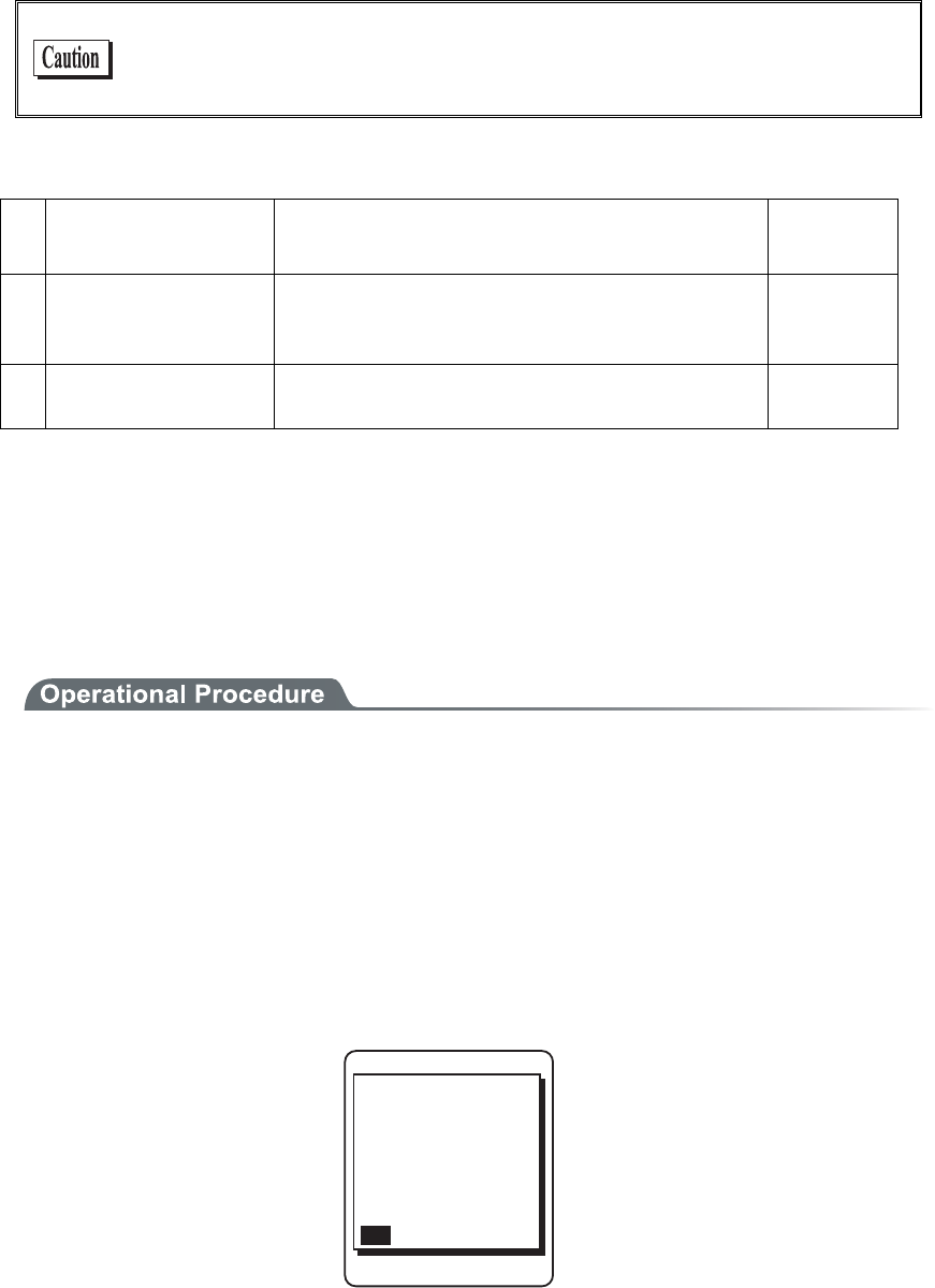
When the GTX-100 is started up without Security setup, the warning screen "NO WLAN Security
" is displayed.
VQIGVUGVWR&Q
[QWYCPVVQUVCTV
OC[QEEWT$GUWTG
UGVWRPQY!
;'501
QH9.#0KUKPXCNKF
5GEWTKV[RTQDNGO
'PET[RVKQPU[UVGO
Though it is possible to make this warning screen being not displayed, this is not recommended for
Security reason. Please set this screen if there is no special reason for not displaying it.
4. From System menu, set up TCP/IP. (P.3-35)
5. When setup is complete, first perform the Ping test toward the IP address of the access point, then
toward the IP address of the computer.

1-3 Wireless Communications
1-9
6. Setup FTP to transmit and receive a file.
・See P.3-53 for transmitting a file to a host computer from the GTX-100.
・See P.3-46 for receiving a file from a host computer to the GTX-100.
In the case using the DHCP function (P.3-36), "WebGlider-X" is required
separately.
■In the case of Bluetooth communication
The procedure to perform Bluetooth communication is as follows.
1. Starting up the host computer in which "BluePorter" is installed.
2. Connect the Bluetooth USB adapter to the USB port of the computer.
3. Starting up the "BluePorter", and perform the setup required for transmission or reception of files.
4. Turn ON the GTX-100, perform setup for connection and so on.
5. Perform transmission or reception file.
・See P.3-53 for transmitting a file to a host computer from the GTX-100.
・See P.3-46 for receiving a file from a host computer to the GTX-100.

Chapter 1 Hardware
1-10
1-4 Product Specifications
CPU 32 bit RISC CPU
OS μITRON
16MB(including12MB for file area) ROM
Download file has 6MB max .In case the extension is "wav" or
"out", the download file has 5MB max.
Memory
RAM 16MB(including 6MB for file area)
Codes scanned NW-7, CODE39, JAN-13/8(add-on: enabled), UPC-A/E, Indus-
trial 2of5, ITF, CODE93, CODE128, EAN128, RSS-14 (Stack:
enabled), RSS Limited, RSS Expanded*4
Number digits scanned MAX 74 digits (data digits)
Scanning width MAX 360mm
Light source Red light semiconductor laser
Laser class Class2 (JIS C 6802)
MAX output 1mW
Wavelength 650±10nm
Scanning speed 100scanning/ seconds
PCS 0.45 or more (reflectance space and margin: 70% or more)
Scanner
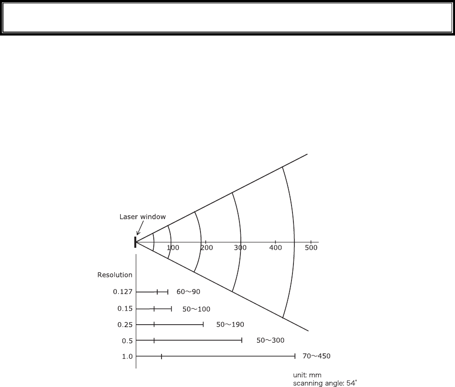
Resolution 0.127mm
SCAN LED Green / Red / Orange LED
ALARM LED Orange (which illuminates when out of range)
Display element FSTN dot matrix
Display size dots 132(W)×128(H)
Display Characters (Kanji) 10 chracters×10 lines (12dot font)
8 chracters×8 lines (16dot font)
Display Characters
(Single-byte characters)
20 chracters×10 lines (12dot font)
16 chracters×8 lines (16dot font)
Display area 38(W)×44(H) mm
Display Characters JIS level-1 kanji set, JIS level-2 kanji set, ANK, Symbols, exter-
nal characters. (Wide, tall and quad characters are enabled)
Contrast adjustment 8 levels
LCD
Backlight White LED (Luminosity adjustable)
Speaker Beep sound, audio, play via speaker.
At the time of scanning, various kinds of Error (can be specified
by the user)
Vibrator Vibrated at the time of scanning, various kinds of Error (can be
specified by the user)
Key Input part Keys 27
Size 58(W)×162(D)×40(H) mm
Grip part45 (W)×26(H) mm
Weight Approximately 204g(battery pack included)

1-4 Product Specifications
1-11
Cradle charging function Enabled (However the environment during charging conforms to
charger's temperature specification)
Main Battery Lithium-ion battery Power
Backup Battery Lithium-ion battery (Maintenance free)
Working temperature -5 to 50°C
Working humidity 20 to 80% (non condensing)
Storage temperature -10 to 60°C
Storage humidity 10 to 90% (non condensing)
Drip-proof / Dust-proof IEC IP54
Drop impact proof 1.5m (onto concrete)*5
Operating
environment
Illumination conditions Artificial light up to 4,000lx
Sunlight up to 80,000lx
Continuous operation time Approximately 24 hours
Setup conditions: scan once in 20 seconds WLAN transmission
or reception
Clock function Year (4 digits) Month/Date/Hour/Minute/Second
With automatic leap year compensation, With timer function
Specification Bluetooth Specification Ver1.2
Communication
Method
Spread spectrum (frequency hopping)
Frequency 2.4GHz band
Communication
rate
MAX 921.6kbps
Transmission
power class
Class2
Antenna Built in the body
Bluetooth
Communication
distance
MAX 10m *6
Standards IEEE802.11b/g
Communication
Method
DSSS, OFDM
Frequency 2.4GHz Band
Antenna power
output
Less than 10mW/MHz
Transmission
rate
OFDM:54/48/36/24/18/12/9/6 Mbps
DSSS:11/5.5/2/1 Mbps
Number of
channels
11
Authentication Encryption
WEP(40/128) OPEN, SHARED WEP(40/128)
WPA-PSK(compartible) TKIP
WPA2-PSK(compartible)
PSK
CCMP(AES)
Wireless part
WLAN
Security
WPA(compartible) EAP-TLS, TKIP

Chapter 1 Hardware
1-12
WPA(compartible) EAP-TEAP-MSC,
HAPv2
CCMP(AES)
Antenna Built in the body
Transmission
range
Indoors:MAX 75m, outdoors:MAX 200m
Management function SNMP agent
Support MIB MIB-II (RFC1213), Welcat Enterprise MIB
*4 The RSS Expanded Stacked specification is supported only partially. Please consult our sales department for
details.
*5 This is a test value, not a guaranteed value.
*6 To ensure stable and reliable communication, we recommend that you use the terminal at a distance within
two meters from the Bluetooth USB adapter with no obstacles in between.
NOTE: You may use Bluetooth and Wireless LAN function simultaneously and it is guaranteed to make
no malfunction on the normal use.

1-4 Product Specifications
1-13
■Display of ALARM LED during wireless communications
The state and meaning of the alarm LED during wireless communications are as follows.
LED state Meaning
OFF Communication with an access point is possible. Or no commu-
nication is currently taking place.
Blinking Continuous blinking during EAP authentication (P.3-29)
ON Communication with an access point has been attempted but syn-
chronization with the access point cannot be achieved. When the
barcode scanner goes out of sync with the access point, the LED
will turn ON.
■SCAN LED Display during terminal charging
SCAN LED status and Meaning during terminal charging is as follows.
LED status Meaning
Red ON Performing terminal charging.
Green ON Charging terminal has normally completed.
OFF During terminal charging, an Error occurred.
Chapter 1 Hardware
1-14
1-5 Scanning Specifications
■Laser light irradiation angle
The angle of the laser light irradiated from the GTX-100 is 54 degrees.
■Scanning Depth
The range across which a Barcode can be scanned is called a "scanning depth."
The scanning depth for the GTX-100 is as shown in the figure below.
1-5 Scanning Specifications
1-15
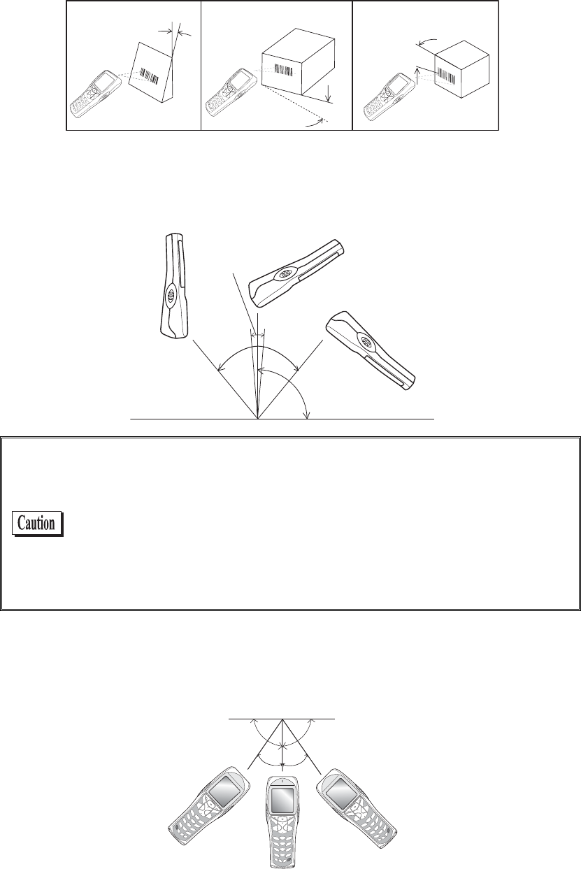
■Inclination of a Barcode and the angle with which it can be read
The following are the three kinds of a Barcode inclination
SKEW PITCH TILT
TILT
PITCH
SKEW
●Skew
Scanning is possible up t o 50°perpendicular to the upper and lower sides of a Barcode.
¹°ā
µ°ā
øā
µ°ā
The range of ±8º around a vertical line from the front face of a bar code
is the “Dead Zone” caused by the specular reflection; poor or erroneous
scanning or other negative effects may occur within this range. In par-
ticular, special care is required when scanning barcodes with high
surface reflection. When scanning such a barcode, you can avoid a
scanning error by changing the scanning angle, changing the material
of the barcode label and some other measures. Change the angle if you
cannot read the barcode and scan it again.
●Pitch
Scanning is possible up to 35° perpendicular to the right and left of a Barcode.
¹°ɨ
³µɨ³µɨ

Chapter 1 Hardware
1-16
●Tilt
The Tilt is the angle with which the laser light irradiates the Barcode.
Tilt angle Ă20ā
Margin
Dz
ąą
Dz
The laser light should always cross the whole label. Irradiating only part
of a barcode as shown in the illustrations marked with “×” may cause
erroneous scanning results. Some margins are required on both the left
and right sides of a barcode. Scanning may become poor if there are any
characters or ruled lines in the margins.
Measurement Condition is as follows.
・ 110mm from the head of the Laser scanner module.
・ Used label
At the time of measurement of pitch angle, skew angle, dead zone:
PCS=0.9, Resolution=0.25mm, 9 digits Code39, Narrow/Wide ra-
tio=1:2.5, margin=10mm
At the time of measurement of tilt angle:PCS=0.9, Resolution=0.26mm,
13 digits JAN, margin=10mm
1-6 Charging Specification
1-17
1-6 Charging Specification
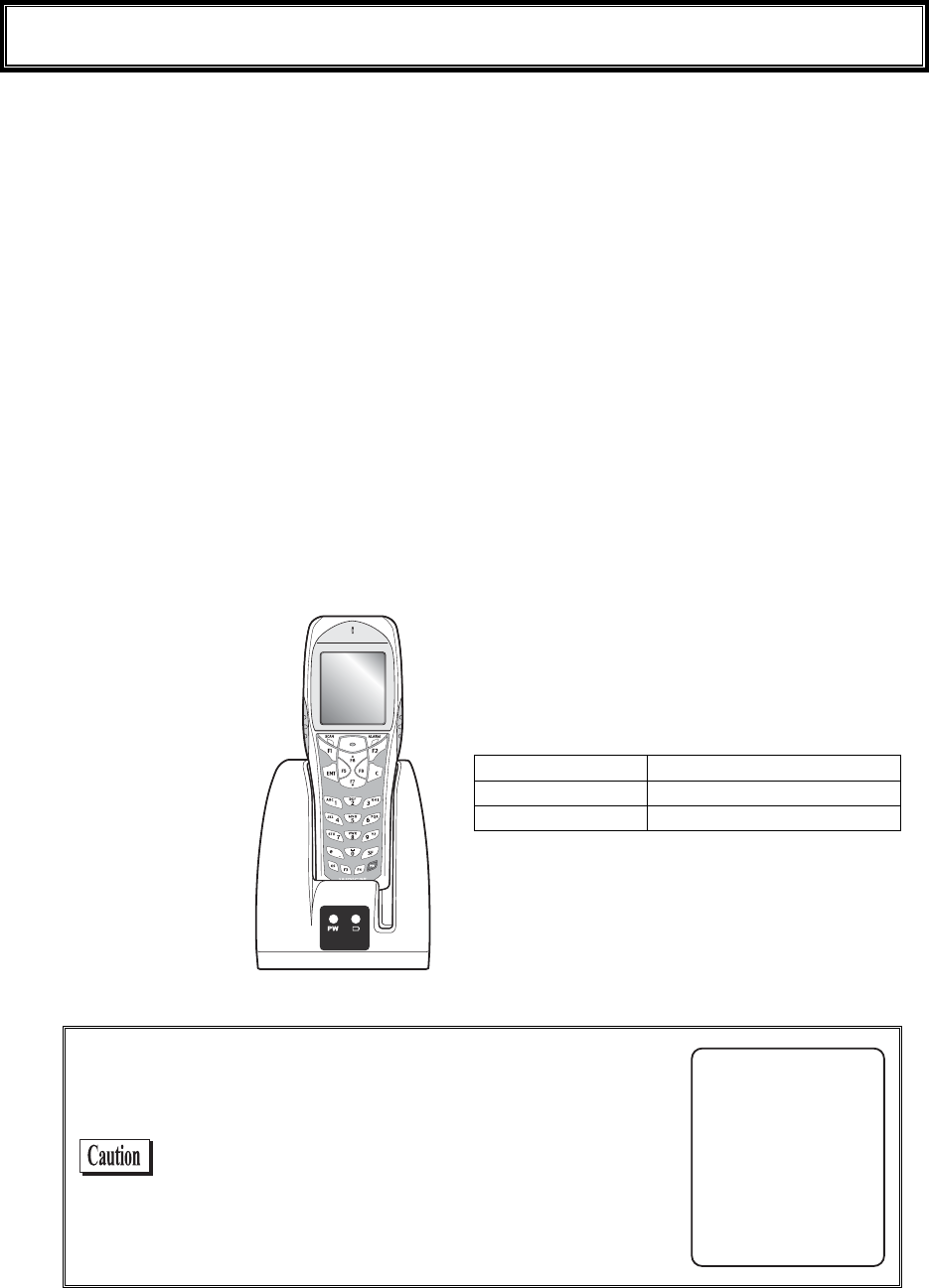
1-6-1 Charging the Battery Pack
GTX-100 allows charging with a battery pack installed on the terminal by using dedicated charger
(GTC-1/GTC-2). Though the operation can be performed in this status, but be sure to avoid the key operation
lest it may fall or cause poor contact with the charging terminal.
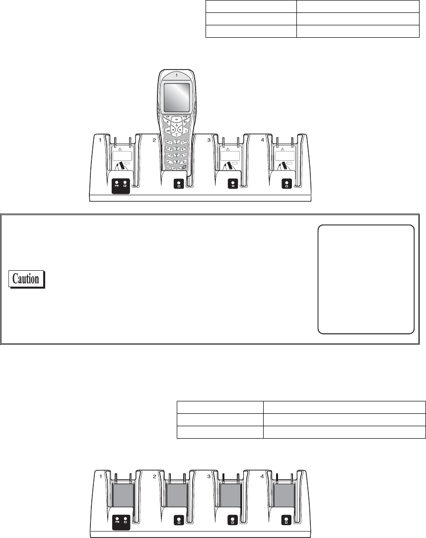
1-6-2 Charging Method using Single Charger (GTC-1)
When the GTX-100 and the battery pack are set at the same time, the GTX-100 charging has a priority. After the
GTX-100 charging completed, the battery pack charging starts.
The chargers can be connected by using the joint enclosed in the Single Charger (GTC-1). (Limited to single
Charger). However carrying them as connected gives a large load on the joint fixed part, take care in handling.
When more than four chargers are connected, please use the Multi Charger (GTC-2).
■Charging with the battery pack attached to the GTX-100
During charging, the SCAN LED on the GTX-100 will turn ON red, when charging completed turn
ON green. Charging time is approximately 2.5 hours.
Take notes to the direction of the GTX-100 when set it on the charger.
Place the GTX-100 in
the charger as shown
b
elow.
During charging SCAN LED red turn ON,
Charging complete SCAN LED green turn ON,
Charging Error SCAN LED turn OFF,
In case an error occurred during charging in the
state of running on, the screen on the right will be
displayed for 5 seconds, and then the power will
turn OFF.
=%JCTIG#NGTV?
5JWVFQYP
%JCTIG'TTQT
Chapter 1 Hardware
1-18
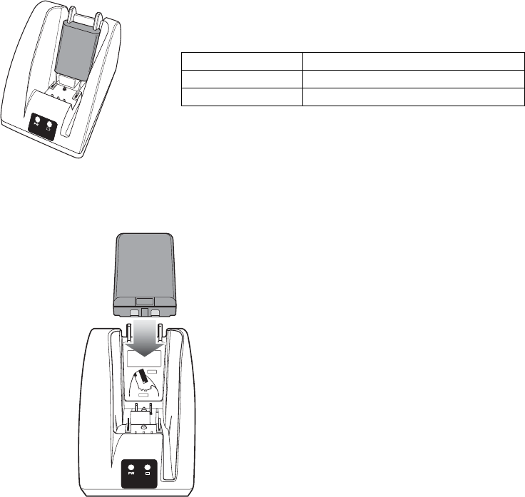
■Charging the Battery Pack alone
During charging, the Battery charging LED in the upper part of battery mark on the front of the
charger turns ON red, while charging has completed it turns ON green. Charging will be completed in
approximately 2.5 hours.
During Charging Battery charging LED red turn ON
Charging complete Battery charging LED green turn ON
Charging Error Battery charging LED turn OFF,
Please take care for the direction of the battery pack when you set it on the charger.
Place the battery pack in
the charger, as it should
turn a label side to the back,
and should set a electrodes
downward.
1-6 Charging Specification
1-19
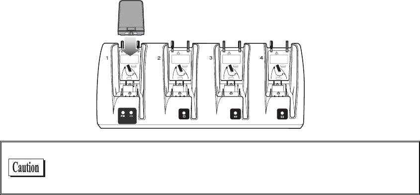
1-6-3 Charging Method using Multi Charger (GTC-2)
The Multi Charger (GTC-2) allows charging many batteries simultaneously. In the GTX-100 and the battery
pack which are set in the same number as that of the Multi Charger, the GTX-100 charging has the priority; the
battery pack charging starts automatically after the GTX-100 charging has completed.
■Charging the battery pack attached to the terminal.
During charging the SCAN LED on the
GTX-100 terminal will turn ON red, when
charging completes turn ON green. Charg-
ing time is approximately 2.5 hours.
Take notes to the direction of the GTX-100
when set it on the charger.
During charging SCAN LED red turn ON
Charging complete SCAN LED green turn ON
Charging Error SCAN LED turn OFF,
Place the GTX-100 in the
charger as shown below.
When error occurred during charging in the state of
running on, the power will turn OFF displaying the
screen on the right for 5 seconds.
=%JCTIG#NGTV?
5JWVFQYP
%JCTIG'TTQT
■Charging a battery pack alone
While charging, the LED on the up-
per part of the mark on each battery
turns ON red, and when charging
completes, it turns ON green.
Charging time is approximately 2.5
hours.
During charging Battery charging LED red turn ON
Charging complete Battery charging LED green turn ON
Charging Error Battery charging LED turn OFF,
When setting battery on the charger, please take notes to the direction of the battery pack.
Chapter 1 Hardware
1-20
Place the battery pack in the
charger, as it should turn a label
side to the back, and should set
a electrodes downward.
When charging Error occurred, charge it again. If the error occurs re-
peatedly, remove the battery and contact our sales department. Take care
not to use the battery that the error occurred.
1-7 Battery pack (GTB-1)
1-21
1-7 Battery pack (GTB-1)
1-7-1 Charging the Battery Pack
Be sure to follow the precautions below when handling the battery pack.
・ After purchasing, be sure to fully charge the battery pack before using.
・ Be sure to shut off the power before removing the battery pack. If the battery pack is removed during
operation, the data file in the S drive may be corrupted.
・ Be sure not to touch the electrodes with your hand, and avoid dust on the electrodes. Otherwise this
may cause poor contact with the battery pack and the GTX-100.
・ When dirty, wipe clean with a dry soft cloth.
・ When installing and removing the battery pack, use a desk or other appropriate surface as the working
table so that it cannot fall onto you feet.
・ Be sure to attach the battery cover and lock it before use.
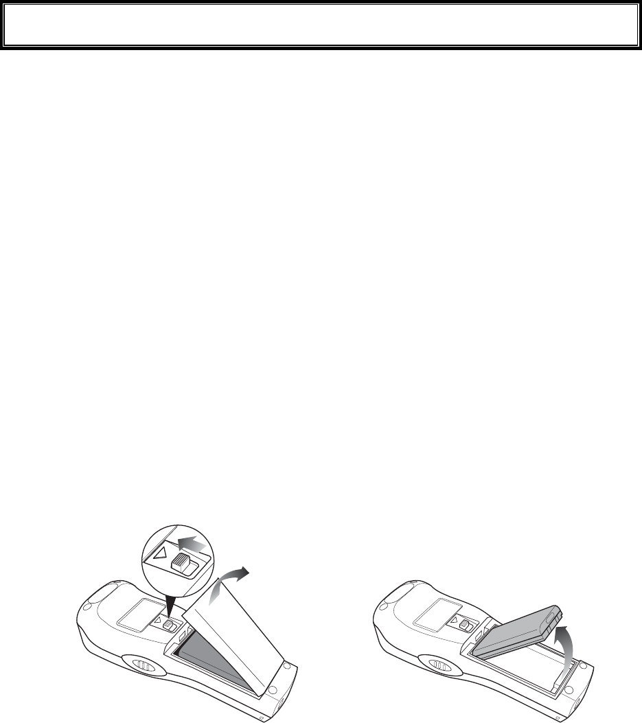
1-7-2 Installing and Removing a Battery
A packing material to protect the water immersion is attached to the Battery cover. When installing the Battery
cover, please confirm if the dust or dirt NOT attached to the packing or the packing inserted correctly. If the dust
or dirt is attached, wipe it softly with dry clean cloth.
■Removing the Battery Pack
2.Remove the battery
cover.
1.Release the lock by
sliding up the lock
lever.
3.Take out the battery pack
from electrodes side.
Chapter 1 Hardware
1-22
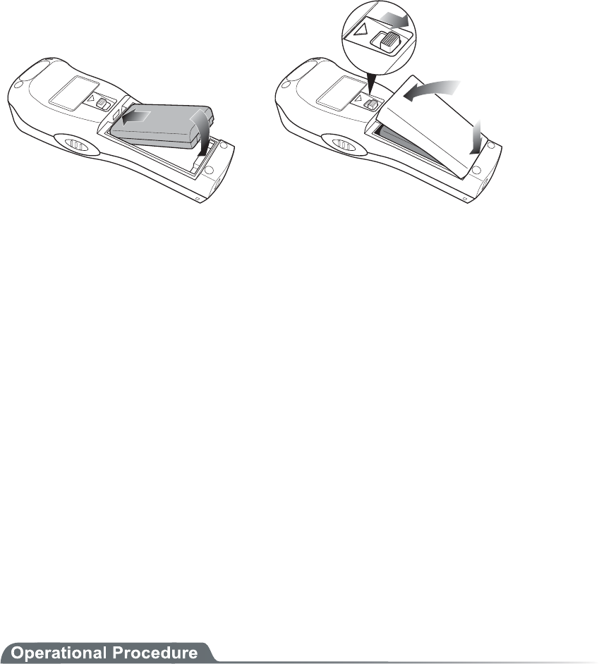
■Installing the Battery Pack
1.Insert the battery pack
in main body cushion
side first.
2.Attach the battery cover to
bottom side first, and lock
by sliding down the lock
lever.
1-7-3 Replacing the Worn out Battery Pack
A battery pack is an expendable item. Even if the battery pack is used correctly, it will deteriorate gradually in
the course of being charged and discharged repeatedly.
If the usage time is becoming shorter even after charging for the specified charging time, please replace the ex-
isting battery pack with a new one.
1-7-4 Cautions about Cleaning of Electrodes
When the operational time has become shorter or it is having trouble starting, poor contact between electrodes
because of dirt, may be the cause instead of a degrading battery. If this is the case, cleaning both the battery elec-
trodes and the main body electrodes will improve this condition.
●Methods for cleaning the electrodes
Please wipe the dirty electrodes with a clean dry soft cloth, a swab, etc. Never rub the electrodes with
an unclean cloth, fingers or a hard object. Wipe the electrodes lightly, especially the main body elec-
trodes, else they may get scratched or deformed.
1-7-5 Charging the Backup Battery
This section describes the Method for charging the backup battery.
1. Put the GTX-100 (with no battery pack installed) and one fully charged battery pack at a handy
place.
2. Install the GTX-100 with the battery pack. The charging process for the backup battery will then be
started. If the Backup Battery has completely been discharged, do not remove the battery pack for
at least two days after the start of the charging process.
1-8 Memory Backup Period (Battery for backup)
1-23
1-8 Memory Backup Period (Battery for
backup)
GTX-100 has two drive areas to store the file: F drive (Non-volatile) and S drive (Volatile). The application data
download from host computer is stored in F drive, so the data won't be lost even if the battery pack has worn out.
(Refer "2-1-1 Data Storage" "■Information about the data storage (drive configuration)" See P.2-2).
■Memory Back Up by battery pack
Battery Battery pack
Use The operation by GTX-100
Charging time Charging the battery by using a Dedicated charger, Approximately 2.5
hours to complete charging.
Backup Period The data storage period with a full charged battery pack attached is as fol-
lows.
・ The data in S drive and resume (suspended) information:
Approximately 25 days
Notes in Use When the battery pack is removed during operation, the data in the S drive
and resume information will be lost. When temporary storage is per-
formed, be sure to press the key to power off, and then remove the bat-
tery pack. Refer to "1-10 Resume function"(P.1-26) for resume function.
If such an operation as removing a battery pack each time the terminal is
not used (the memory back up by the back up battery is applied), the
backup period will get extremely shortened in approximately half a year.
In this case, the replacement of the backup battery is necessary (paid)
therefore please attach the battery pack except for changing the battery.

Chapter 1 Hardware
1-24
■Memory Back up by backup battery
Battery Battery for Backup
Use The Clock data built in GTX-100 is kept. In addition, The data in the S
drive is saved only for a certain period while replacing batteries etc.
When resume function setup is enabled, the resume information is
stored.
Charging time Approximately 2 days after fully charged battery pack is attached to the
GTX-100.
Backup period Data storage period after removing the battery after Normal termina-
tion*1 is as follows.
・ S drive data and resume information (when resume function is
enabled):Approximately 15 hours
・ Built in clock data:Approximately 6 months
Data storage period after terminating by Mothball Menu*2 is as follows.
・ Built in clock data:Approximately 1 Year
(with or without battery pack)
Notes in Use For details of prolonged storage of the terminal, please refer to"1-9 Not
use in long time" (P.1-25).
The data lost due to the worn out of the battery for back up will not be
restored. Be sure to save the data other than the temporary one in the F
drive.
*1 Normal termination:The termination method after pressing the key remove the battery pack.
*2 Termination by Mothball :The method to terminate to select mothball from the System menu.
The Memory backup time varies depending on the surrounding envi-
ronment. For example, backup time will be drastically reduced in tem-
perature below 0°C and over 40°C and more. It is recommended to use
the battery at room temperature.

1-9 Not use in long time
1-25
1-9 Not use in long time
■Not use in long time (the terminal)
If you do not use the terminal for a long period (more than 6 months), it is recommended to setup the
terminal to Mothball, the power will soon turn off.
By Mothball setup, though the data in the S drive and resume information will disappear, the built in
clock data will be kept, thus saving the consumption of the battery. About setup method, refer to "
3-15-6 Mothball"(P.3-84) for the Setup method of Mothball.
■Not use in long time (the battery) for Battery
When you do not use the battery for an extended period of time, setup the terminal to Mothball and
removing the battery to keep it in a cool spot charged about 50%. When you do not use it for one
month or more, remove the battery pack and keep it at room temperature.
The battery may deteriorate rapidly by over discharging or under high temperature.
Chapter 1 Hardware
1-26
1-10 Resume function
The GTX-100 supports resume function, from System menu, setup, the behavior of the power on by the key.
For setup method, see "3-8-3 Resume (resume function)"(P.3-17).
Resume function enabled After pressing key to turn off the GTX-100 and start up with the
key, the processing resumes what was executed immediately be-
fore the power off.
Resume function disabled After pressing key to turn off the GTX-100 and start up with the
key, the processing always starts from the first stage.
Please be informed that when the battery pack is removed during the
operation of the terminal, the program will be executed from the begin-
ning regardless whether the resume function is enabled or disabled.
Please be informed that when the back up battery is consumed, the
program will be executed from the beginning regardless whether the
Resume function is enabled or disabled. With regard to charging the
battery for backup, please refer to "1-7-5 Charging the Backup Bat-
tery"(P.1-22).
1-11 Screen Output Characters
1-27
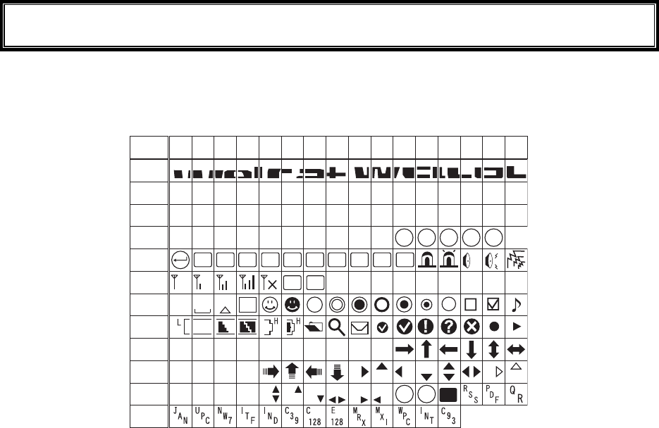
1-11 Screen Output Characters
■Welcat specific Double-byte characters
ᴥ±ᴦ
æ°´°
°±²³´µ
¶·
¸
¹
ÁÂÃÄÅ
Æ
æ°µ°
æ°¶°
æ°·°
æ°¸°
æ°¹°
æ°á°
æ°â°
æ°ã°
æ°ä°
æ°å°
æ°æ°
Ʊ
ᴥ°ᴦ ᴥ²ᴦᴥ³ᴦᴥ´ᴦᴥµᴦᴥ¶ᴦᴥ·ᴦᴥ¸ᴦᴥ¹ᴦ
Ð× Ã ÂÓ ÓÆ
ƳƲ Æ´ Ƶ ƶ ( Æ ¸
ˁ
Ó
ÎÕÓÈÓØÅØÅÔ
ÄÌıIJijĴ
ÅÑÁËÂÌ
ÎËÓÙÅÂÃÎÅÍÓÂ
ÂÓÈÔÌÆÖÔÆÆÃÒÓÏ
ÅÃÆÓÇÓÒÓÕÓ
ÓÉ
°
Ô
Óèéæô
ÊÉÓ
ÅÎÔ
ƹ
Ʊ°
ÒÌ
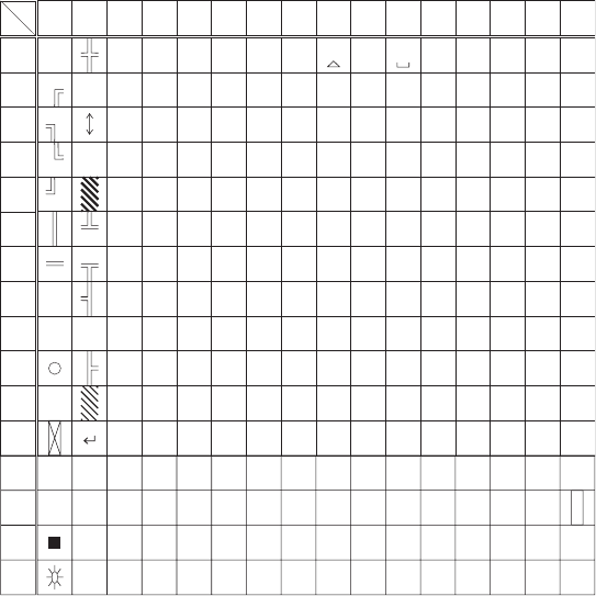
Chapter 1 Hardware
1-28
■Single-byte characters
°±²³´µ¶·¸¹ÁÂÃÄÅÆ
°
±
²
³
´
µ
¶
·
¸
¹
Ã
Ä
Á
Â
Å
Æ
ᴞ
ž
ᴭ
ᴮ
ᴯ
À
Á
Â
Ñ
Ð
Ò
ᴠᴰÃ Ó
ᴡᴱÄ Ô
ᴢᴲ Å Õ
ᴣ
ż
ᴳÆÖ
ᴴÇ×
ᴥᴵÈ
ᴦᴶÉ
Ø
Ù
ᴷÊ Ú
ᴨᴸË ᵘ
ᶁÌᴩ
ᴪᴺÍᵚ
ᴹ
ᴫ
ᴬ
ᴻ
ᴼ
Î
Ï
ᵛ
Żð
áñ
òâ
óã
ôä
õå
öæ
ç÷
øè
ùé
êú
ᵸ
ë
ᵹì
íᵺ
îᵿ
ï
ǿ
˂
ɬ
ʉ
ʋ
ʩ
ʪ
Ȉɮʎʫ
ȉɰʐʬ
ʒʮɲǾ
ˁɴʔʰ
ʲʕɵʼ
ɫɷʖʳ
ʴʗɹɭ
ɯɻʘʵ
ɱɽʙʶ
ɳɿʜʷ
ʭʁʟʹ
ʯʃʢʽ
ʱʅʥɧ
ʍʇʨɨ
Ƣ
ơ
Ɵ
ᵹ
Ơ
Ó
о
ӌ
ᴧ
ᵜ
Lower
Upper

Chapter 2
2 Software
Chapter 2 Software
2-2
2-1 GTX-100 Software
The GTX-100 Software consists of the following two types.
System program
Controls the basic operation of the GTX-100. It is equivalent
to an OS (operating system) of a personal computer, and is
preinstalled in the GTX-100. The System Menu, which sets
the basic parameters for operation and performs various veri-
fications, is a part of the system program.
Application program
Used for user operations processing. This program is mainly
used for scanning Barcodes, data transmission to a computer,
etc. If you purchase "WebGlider-X", you can easily combine
it with the WebGlider-X Browser to build a Web based sys-
tem. If you purchase "Handy5250", it allows you 5250 emu-
lation and configures the handy terminal system with high re-
liability of AS/400 host computer.
Refer to "Chapter 3 System Menu" (P.3-2) for detailed information about
the System Menu.
For information about "WebGlider-X," see the online manual included
with the product package.
2-1-1 Data Storage
■Information about the data storage (drive configuration)
The GTX-100 has two drives for storing data. The S Drive and the F Drive.
Drive Data Retention Use Maximum Capacity
F drive ●Non-volatile memory
The contents of this drive
will be retained after the
backup battery is dis-
charged.
Used to store all files, such
as application, the database
master files and normal data
files, etc.
64 files
S drive ●Volatile Memory
Once the battery pack is
suddenly removed during
operation or the backup
battery is discharged the
contents of the drive will
be lost.
S Drive Used to store tem-
porary files when an appli-
cation is running on.
64 files
When the F Drive receives a file, the S Drive receives the file first then moves it to the F Drive.
In case where the F Drive receives a file, confirm that there is enough storage space on both the S
Drive and F drive beforehand.
When receiving files if there is a file with identical name on the S drive, the old file will be erased.

2-1 GTX-100 Software
2-3
■File Naming
The file names used by the GTX-100 are subject to the following restrictions.
File name length A file name allowed to enter is up to 31byte long, including
extension.
Characters that
can be used.
Characters can be composed of as any combination of the fol-
lowing characters.
・ Alphabet(A to Z)
・ Numbers (0 to 9)
・ Symbols(!#%&'()@^_{}~.)
・ Single-byte space
Other restrictions A space, or, "."(Period) is prohibited to use at the head of the
file name.
■About extensions
The GTX-100 recognizes files through extensions.
".OUT" Recognizes as an application.
".WAV"
".MP3"
".SFL"
Recognizes as audio data.
Subject to format restrictions for the WAV file and MP3 file that
can be played on GTX-100. (P.3-49)
SFL is a system original style text file. (P.3-49)
".BMP" Recognizes as a Bitmap image.
The bitmap file displayed on GTX-100 is subject to format re-
strictions. (P.3-49)
■The files generated by the system and application
A part of the System program and application program of the GTX-100 create a temporary file and a
file to save the setup value. If these files could not be generated for such reasons that there are too
many files, or no space in the drive etc., each program fails to work normally.
System program generates a registry file in the F drive to save the Setup value of the System menu.
Four files are created in this case, however, this is a hidden file and not displayed in the System menu.
By using WebGlider-X browser following files are created in the S drive during HTTP communica-
tion.
Since a file with the same name is overwritten, be sure to use a different name than the following file
names.
・ HTTP.LOG
・ HTTPTEMP (with no extension)
・ HEADTEMP (with no extension)
When an application is programming, and SQLite Library is used, a temporary file will be created in
the S drive during database operation. The file name will be created randomly to avoid overlapping
with the existing file.

Chapter 2 Software
2-4
2-2 System menu
Through the System Menu, you can make the GTX-100 fundamental operation settings, install the application
program and transmit data files, etc.
Refer to "Chapter 3 System Menu" (P.3-2) for details about the System Menu.

Chapter 3
3 System menu

Chapter 3 System menu
3-2
3-1 Introduction
The System menu is a part of the system program, which is preinstalled in the GTX-100 as one of the functions
that comprise the operating system. It also provides a platform for installing application programs and perform-
ing environmental setup for the whole system.
This chapter describes how to set up the GTX-100 and perform various verification checks, with primary focus
on how to use the "System menu."
3-2 Save the System Parameter
3-2-1 Registry
The system parameters that are set up in the System menu are called "Registry".
In addition, as these registry files are not displayed in the System menu as these are hidden files. As the registry
is saved in the F drive, it will be not erased even though the back up battery is worn out.
Registry is classified into five categories as below.
User Registry General set up value. Most part of the items setup in the System
menu creates the User Registry.
Security Registry Security related setup value such as WEP key and SSID etc.
Unique Registry Setup value unique to the terminal such as IP address and terminal
ID, which generally does not overlap to the other terminals.
System Registry Using a unique setup value used by the GTX-100.The execution of
Setup or reference from the System menu is not enabled.
Device Registry This is the item such as Battery level or radio signal level that is to
refer the parameter that changes in real time during the operation
of the terminal. The setup value that belongs to this device registry
can only be referred to, but unable to setup.
The four registries except for Device registry are saved in an independent file respectively. For this reason there
are four files are always stored in the F drive of GTX-100. As the registry is stored in the F drive, it will be not
erased even if the battery is disconnected.
The Device registry is not saved in a file, as it varies according to the operation status of the terminal.
Please refer to "Appendix. A-1 System menu Factory Settings"(P.A-2) with regards to what menu the setup
value belongs to.
The Clone (P.3-80) allows the other terminal to copy the registry and duplicate the terminal with the same setup
as that of the original.
By using "initialize" Menu (P.3-78), the registry will be erased, restoring the terminal to the status of Factory
Setup.
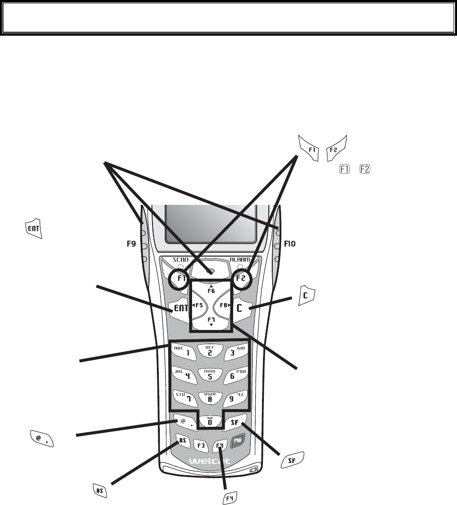
3-3 Key Names and Functions
3-3
3-3 Key Names and Functions
This Chapter explains about keys and functions used in the System menu.
In this Manual each key is described as follows.
ǽëåù
Äéòåãôéïîëåù
key
Switches the character input mode.
ëåù
ëåù
Ten key
ëåù
ȆUsed to return to the
previous menu.
ȆUsed to clear all the
characters entered.
ȆUsed to enter assigned
number and characters.
ȆUsed to select the corre-
sponding menu item.
ǽ¯ëåù
Óãáîëåù
ȆPress this key to read a barcode.
ȆIn the system menu, F9 and F10 key
also have the same function as a scan
key.
ȆUsed to confirm an op-
eration or the Selected
menu item,
ȆUsed to confirm input-
ted data.
Ȇmove the selected item When
entering character
Ȇmove the cursor to the direction
shown by the arrow.
ȆChange the upper-case/lower-
case of the entered character.
When or is displayed, the
corresponding key is pressed to
display the sub menu or exe-
cute assigned functions (special
features).
Turns on/off the back light
each time the key is pressed.
When the battery level is lower
than the regulated value, the
backlight does not turn on.
Delete an entered char-
acter.
Input Symbols and decimal
points.
ëåù
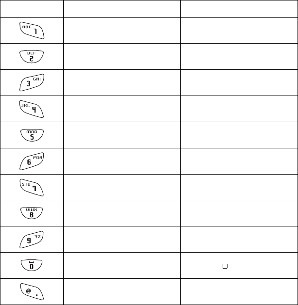
Chapter 3 System menu
3-4
■Assigned key character list
Key Numeric input mode Alphabet input mode
1 ABC
2 D E F
3 G H I
4 J K L
5 MNO
6 P Q R
7 S T U
8 V W X
9 Y Z
0 (space)
・ $-+/%:#@&
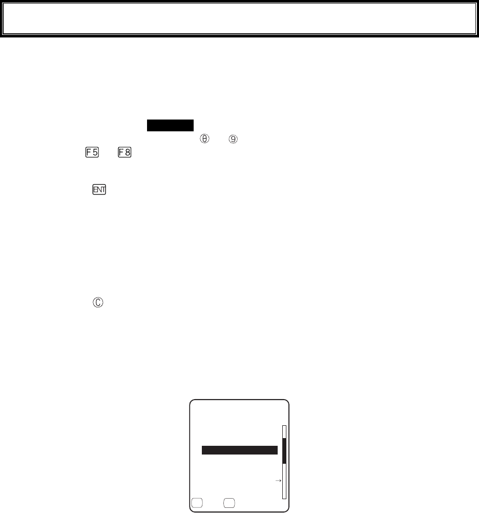
3-4 System Menu Operations
3-5
3-4 System Menu Operations
Here explains the Standard Operation Method of the System menu.
■Select the target item from the menu
●Selecting a Menu Item
Selected item becomes highlighted (colors reversed= selected).
Move the cursor either by pressing
to key, which corresponds to the item, or, by using the di-
rection ( to ) key.
●confirm the selected item
Press the key, and, confirm the selected item.
The behavior after confirmation differs according to the item.
・ Execute the corresponding function
・ Show the decision [Yes] or [No] (check box)
・ Next Menu is displayed.
・ Sub menu is displayed.
●Cancel Selecting
Press the key, to return to the previous operation.
●Screen display
When the items in the Menu are not housed in a screen, the scroll bar for vertical direction is dis-
played on the right of the screen. In addition, when the item name exceeds 1 line, the tail of the item
name is displayed being converted in "→ "
(KNG(
ǫ*#$#0'41$/2
ǫ%12#0$/2
ǫ+0&':*6/
ǫ.10).10)(+.'0#/'
ǫ/#-'6:6
ǽ/GPWǽ5&TKXG
( (
ǫ:$/2
ǫ9):$176
■Input Barcode data
●Barcode Scanning
Press the scan key and irradiates the laser to scan a barcode.
The irradiation time of the laser and scanning behavior are set up with trigger mode. In addition, Bar-
code test menu is not subject to trigger mode.
●Barcode scanning condition
The Barcode that can be scanned in the data input mode is as follows.
NW-7, CODE39, JAN13/8, UPC-A/E, Industrial 2of5, ITF, CODE93, CODE128, RSS-14, RSS
Limited

Chapter 3 System menu
3-6
■Input by the key
●Switching the Character Input mode
GTX-100 allows inputting characters using numeric keys and key.
The character allowed to enter is Numeric, Alphabet (upper-case/lower-case) and Symbols, changing
input modes according to the character to enter.*1
・"Numeric input mode"
Numeric and decimal point are allowed to enter.
・"Alphabet input mode"
Alphabet (upper-case/lower-case) and Symbols are allowed to enter.
Each time the key is pressed, the input mode changes。*1
●Numeric input
Make the character input mode to numeric input mode( cursor: ■(rectangle)).
Press
to key, and input corresponding numeric. Press the key, and input decimal point.
●Alphabet input
Make the character input mode to alphabet input mode( cursor:_(under bar)).
Press to key, and input the assigned alphabet.
When an assigned Alphabet on the same key is continuously entered, press the key to move the
cursor, and input the next alphabet.
Press the / key, and alphabet at the cursor position changes ;Upper-case character ⇔
Lower-case character.*2
●Input the symbol
Make the character input mode to alphabet input mode( cursor: _ (under bar)).
Press the
key, or
key, and input the assigned symbol.
When an assigned symbol on the same key is continuously entered, press the key to move the
cursor, and input the next symbol.
When the cursor is at the end of the entered data, press the
key, and a space is inserted to the
right of the cursor.
*2
●Confirm the entered data.
Press the
key.
●Delete the character
*3
Press the key, and delete the character at the cursor by 1 character.
Press the key, and delete all characters.
●Cancel the input
In such an item that deleting characters is not allowed (refer to
*3
), press the key, and stop the in-
put immediately. In such an item that deleting characters is allowed, after deleting all characters en-
tered and press the key.
●Others
When the input characters are filled over the field length, the cursor returns to the top.
*
1
The item that the kind of characters allowed to enter is restricted ( example:terminal ID is nu-
meric only )cannot change the Input mode.
*
2
The Characters allowed to enter may be restricted according to the item.
*
3
In the item of which format to enter is fixed(example:IP address) the character cannot
be deleted. In this Manual the Input Format fixed items are shown with the icon in the
right.
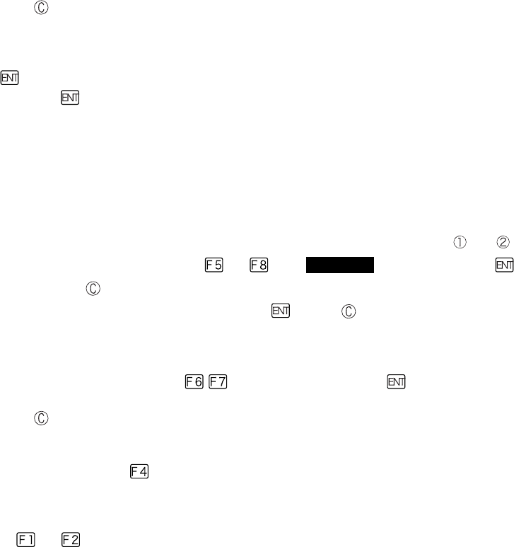
3-4 System Menu Operations
3-7
■Other operations
●Returning to the previous menu.
Press the key.
●Check box operation
By applying or removing checks in the square box, making the item selected/not selected. Each time
the key is pressed, the status of Select /Not Select switches.
Each time the key is pressed ,[Yes]/[No] switches.
The check box is also applied when selecting many items at the same time.
●Radio buttun operation
The item the inside of the small circle is dotted shows that it is currently enabled.
Radio button is used to select one item from many items.
●Message box operation
When two buttons are displayed in the lower part of the box; [Yes]/[No] etc., press or, key, or
select the button by using the direction ( to ) key (Highlighted), and then press the key to
confirm. Press the key to select the right button.
In such a case with one button like "OK", press the key or key.
●Level meter operation.
Setup value adjustment by stages.
Move the slider Up and Down by / key. And then, press the key to confirm the level
value.
Press the key to cancel setup.
●Turning ON/ OFF the backlight.
Each time by pressing the
key, the backlight turns ON/ OFF. However in case the battery level is
less than the regulated value, the backlight does not turn ON.
●Accessing to the Sub menu or function.
When or
is displayed in the lower part of the screen, press the corresponding key to display
the Sub menu or execute the function.
●Modifying the indicator when operating
The indicator (buzzer/audio/vibrator/LED) that works when operating allows itself to be modified to
user's original setup. With regard to the modification Method, please refer to"■Indicator func-
tion"(P.3-71).
By modifying this setup users' are allowed to create their original indicator easily.
In addition, there are some operations that the indicator is not applied.
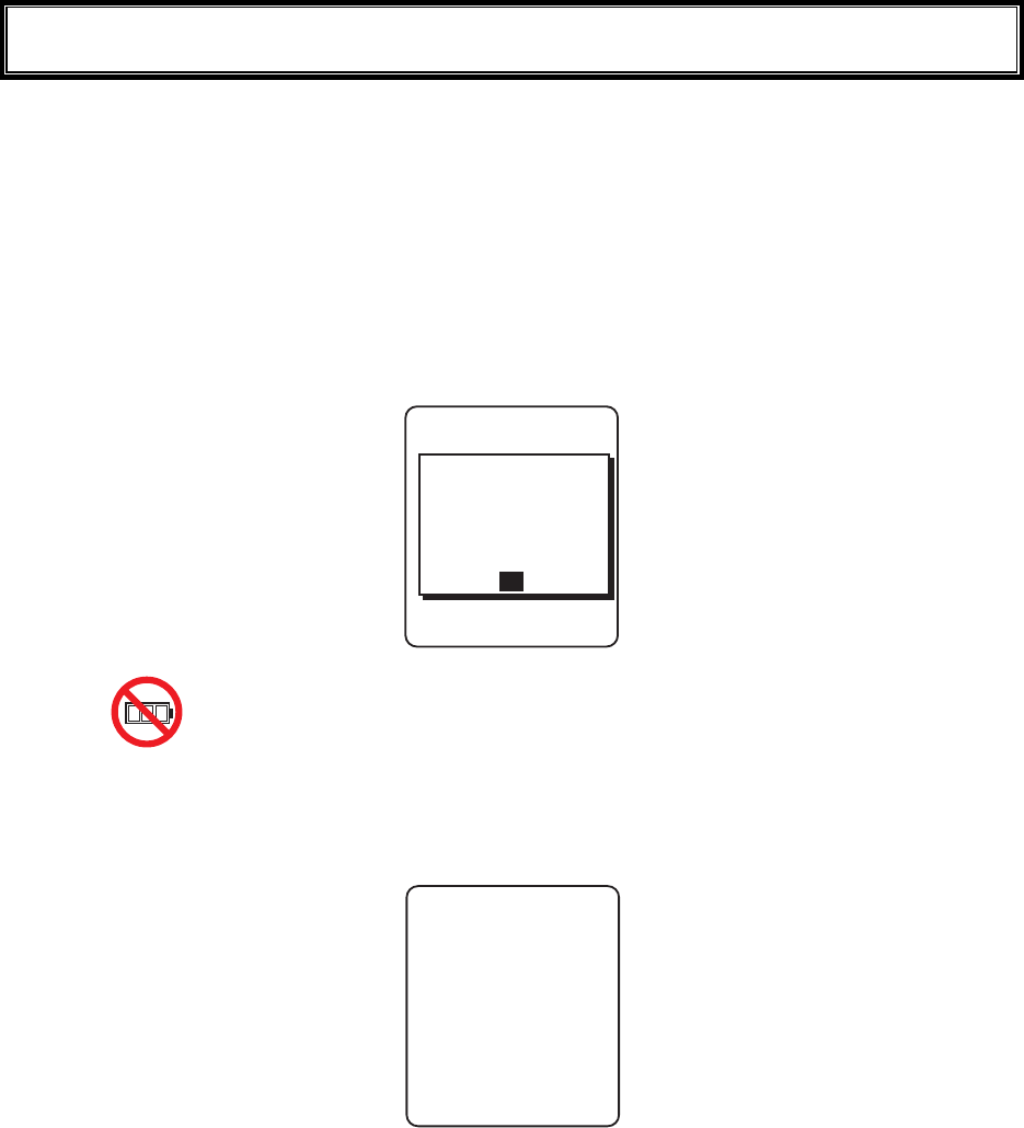
Chapter 3 System menu
3-8
3-5 Battery Level
When the battery level of the battery pack lowered, operation is restricted or the power may turn OFF.
●Checking the current battery level
From the System menu, select"8:Manage", and then "1:Battery level".
●Restricted operation when the battery level is low.
Some operations of the System menu are restricted, when the voltage level is less than the regulation
level (the level differs according to the operation) at the time of execution.
5[UVGOOGPW
.QYDCVVGT[
KUNQY6JGTGHQTG
VJGQRGTCVKQP
$CVVGT[XQNVCIG
ECPPQVGZGEWVG
1-
In this Manual, the operation that will be restricted is shown with the icon.
●Battery Alert
The Display below and the buzzer inform the user of the battery shortage.
ᵘ$CVVGT[#NGTVᵚ
ǽǽǽǽǽǽǽǽǽǽ
2NGCUGEJCTIGKV
8QNVCIGKUNQY
Approximately after 5 seconds, the power is forcibly turned OFF.
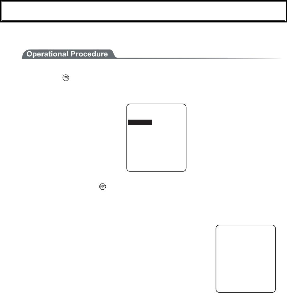
3-6 Starting the System Menu
3-9
3-6 Starting the System Menu
3-6-1 How to Start the System menu
1. Once the GTX-100 has been correctly installed with a battery pack and if the current state is OFF,
press the key for approximately 1 second. The power will turn ON and the System menu will
be started.
2. The System menu is displayed immediately after the opening screen.
5[UVGOOGPW
0GVYQTM/CPCIG
4GEGKXG6GUV
5[UVGO+&
9.#0&GXKEG
(KNG
If an application is set for " Auto execute" (P.3-15), hold down the scan key (excluding F9 and
F10), and then press the key to start the System menu.
3-6-2 Executing a DHCP Request
If the "■Startup type"(P3-37)is setup at[application boot], [System menu boot],
the DHCP request will be executed every time of booting.
If the system is in the state where wireless communications with an access point
is possible and if the DHCP server and FTP server of the "WebGlider-X " Net-
work Manager have been started, the various environmental setting values and
specified files will be downloaded to the GTX-100 and automatic setup will be
perform via the TCP/IP network.
After the DHCP request has been executed, the applications set for "Auto exe-
cute" if any, will start. (P.3-15)
&*%2ENKGPV
&*%2UGTXGT
%QPPGEVVQ
3-6-3 Starting State for Wireless LAN Operation
Immediately after starting, the GTX-100's wireless LAN communication unit is set to a resumed state. If the
wireless communications related menu is selected immediately after starting, the GTX-100 will be ready for
communication within 0.5 to 1 second.
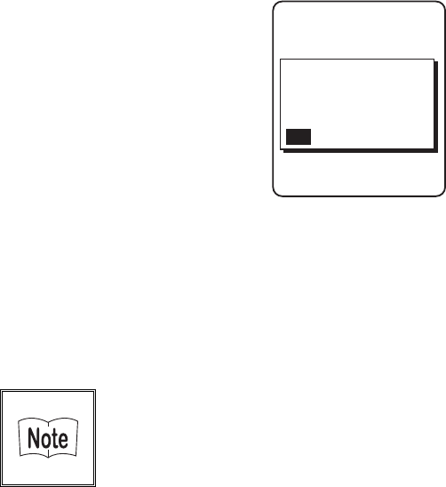
Chapter 3 System menu
3-10
3-6-4 Executing Setup Wizard
At the initial startup of the terminal, the setup wizard is executed to perform the minimum setup of the request
for communication between the terminal and the server.
9K\CTF
%QOOWPKECVKQPUGV
VKPIECPDGFQPG
5VCTVYK\CTF!
YKVJIWKFCPEG
;'501
Select either[Yes]or [No].
Select [Yes], then the wizard will be executed to perform the setup of WLAN and TCP/IP.
Select [No], then the System menu will start up.
When selecting [No] to skip the Setup Wizard, or, completing the setup to the last moment by executing Setup
Wizard, the Setup Wizard will not startup from next time and after.
Each item to be entered in the Setup Wizard can be set up each by each in
the System menu. In addition, Setup Wizard can be arbitrarily executed
from the System menu (P.3-85).
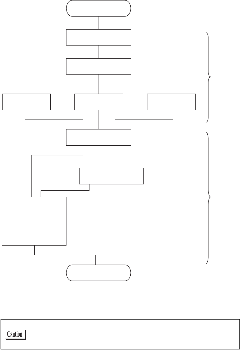
3-6 Starting the System Menu
3-11
With the Setup Wizard, each item is setup respectively according to the flow of the following Chart. The ac-
companying item differs by the branch of the selection.
5VCTV5GVWR9K\CTF
55+&
5GNGEV'PET[RVKQP/GVJQF
9'2MG[VQ
6Z-G[+& 2TGUJCTGFMG[
&*%2
'ZGEWVG&*%2
5[UVGOOGPW
+2#FFTGUU
0GV/CUM
)CVGYC[
(625GTXGT
&055GTXGT
+&
#RRNKECVKQPDQQV
5[UVGOOGPWDQQV
6-+2QT
%%/2#'5
9'2&KUCDNG
&KUCDNG
5WEEGUU(CKNWTG
9.#0
6%2+2
&KURNC[9.#0
UGEWTKV[CNGTV
*1 This is only performed by Wizard Execute when starting up the terminal. When "Wizard Execute" is per-
formed from the System menu (P.3-85). It returns to the System menu without executing DHCP.
WLAN authentication method is not allowed to setup by the wizard.
Especially EAP certification requires receiving the files such as Certificate
etc., complicating the setup, please perform the setup manually.

Chapter 3 System menu
3-12
3-6-5 WLAN Security Alert
When the WLAN Encryption Method is disabled, the dialog to alert the setup is displayed at the time of starting
up.
VQIGVUGVWR&Q
[QWYCPVVQUVCTV
OC[QEEWT$GUWTG
UGVWRPQY!
;'501
QH9.#0KUKPXCNKF
5GEWTKV[RTQDNGO
'PET[RVKQPU[UVGO
Select either from [Yes] or [No]
Select [Yes], moves to "2:WLAN". Select [No], System menu is displayed.
When the resume is enabled, this dialog is not displayed.
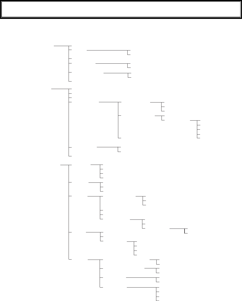
3-7 System Menu List
3-13
3-7 System Menu List
System menu is configured as a structural architecture that is classified for respective functions.
5[UVGO #WVQGZGEWVG
%NQEM
4GUWOG
2CUUYQTF
#WVQYCMGWR
#WVQRQYGTQHH
/CPWCNUGVVKPI
5GTXGTUGVVKPI
5GV
%NGCT
5GV
%NGCT
0GVYQTM 6%2+2
&*%2
(62
&05
50/2
+2#FFTGUU
0GV/CUM
)CVGYC[
/67
5VCTVWRV[RG
7RFCVGRTQVGEV
5GTXGTRQTV
5GTXGT#FFTGUU
7UGTPCOG
2CUUYQTF
#FXCPEGF
2TKOCT[
5GEQPFCT[
#FXCPEGF
%QOOWPKV[PCOG
/CPCIGT+2CFFTGUU
%QOOWPKV[PCOG
/CPCIGT+2CFFTGUU
%QOOWPKV[PCOG
/CPCIGT+2CFFTGUU
5GTXGTRQTV
/QFG
(QNFGT %WTTGPV
5RGEKHKGF
5GTXGTRQTV
6KOGQWVVKOG
6TKCNEQWPV
%CEJGVKOG
%QOOWPKV[ᴥ41PN[ᴦ
%QOOWPKV[ᴥ49ᴦ
6TCR
#FXCPEGF #WVJGPVKEVTCR
#IGPVRQTV
6TCRRQTV
6TCRTGVT[
5GVOGVJQF
#FFTGUU
0COG
9.#0 55+&
4QCOKPINGXGN
&Q\GOQFG
5GEWTKV[
#FXCPEGF
/#%CFFTGUU
'PET[RVKQP
#WVJGPVKECVKQP
#VVGPVKQP
4CVGEQPVTQN
465A6JTGUJQNF
/GVJQF
'#2OQFKH[
/GVJQF
9'2
25-6-+2%%/2
'#2OQFG
%GTVKHKECVG
2TKXCVGMG
[
7UGT+PHQ
#FXCPEGF
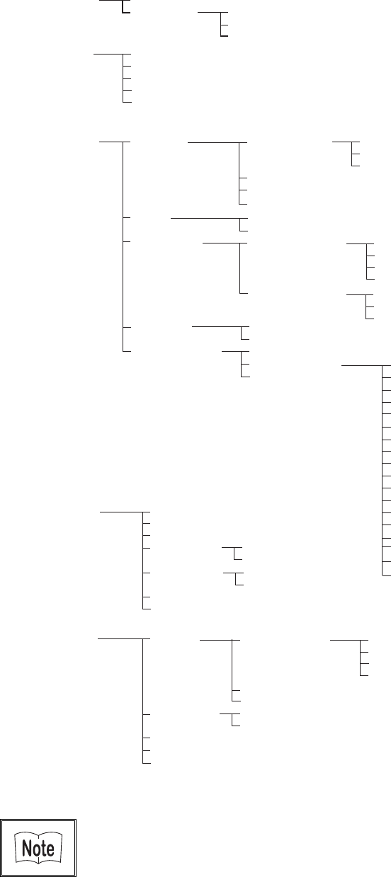
Chapter 3 System menu
3-14
4GEGKXG 9.#0
$NWGVQQVJ
(KNG
+&
&GXKEG $CTEQFG
-G[
$NWGVQQVJ
&KURNC[
6QPG8KDTCVQT
6TKIIGTOQFG
&GEQFGNGXGN
5ECPCPING
4GXGTUG
6TKIIGTQRGTCVKQP
2QYGTUCXKPI
+TTCFKCVKQPVKOG
-G[TGRGCVFGNC[
-G[TGRGCVTCVG
.QECNFGXKEG
4GOQVGFGXKEG
&GXKEGPCOG
$&#FFTGU
5GEWTKV[
8GTUKQP
&GXKEGNKUV
5GCTEJHQTFGXKEGU
5GCTEJQRVKQP
%QPVTCUV
.WOKPQUKV[
8QNWOG
+PFKECVQTHWPE
%NKEMUQWPF
%CPEGN
%CPEGN
%CPEGN
'PVGT
'PVGT
'PVGT
%NKEM
%NKEM
%NKEM
0QVKEG
0QVKEG
0QVKEG
'TTQT
'TTQT
'TTQT
7UGT
7UGT
7UGT
/CPCIG $CVVGT[NGXGN
5[UVGOXGTUKQPU
+PKVKCNK\G
%NQPG
&TKXG
/QVJDCNN
9K\CTF
/CUVGT
%QR[
(&TKXG
5&TKXG
5GNGEVHTQONKUV
9CKV2%
9CKV:+6
#RRNKECVKQP
&CVC
#WFKQ
$KVOCR
#NNV[RG
6GUV 9.#0
$NWGVQQVJ
$CTEQFG
&KURNC[
-G
[
%QPHKIWTCVKQP
9.#0RKPIVGUV
#25GCTEJ
*QUVCFFTGUU
2CEMGVUK\G
6KOGQWVVKOG
6TKCNEQWPV
/CUVGT
5NCXG
Please refer to the "System menu Factory Settings" (Appendix A-2) for
information about the System menu factory settings.
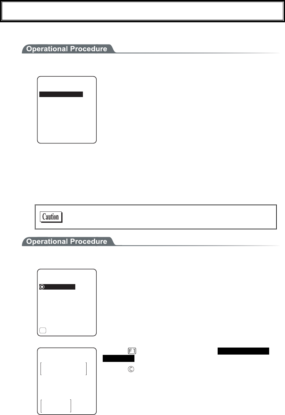
3-8 System Setup Menu
3-15
3-8 System Setup Menu
The setup for convenient functions to facilitate your GTX-100.
1. From System menu, select "1:System".
5[UVGOUGVVKPI
4GUWOG
2CUUYQTF
%NQEM
#WVQYCMGWR
#WVQRQYGTQHH
#WVQGZGEWVG
Select the item to setup.
・ Auto execute
・ Clock
・ Resume
・ Password
・ Auto wake up
・ Auto power off
3-8-1 Setting the programs for Automatic Launch
You can set programs to launch automatically when the power is turned ON. In the factory settings, the System
menu is set to launch automatically. When the DHCP function is enabled, these settings can be made automati-
cally.
In the case to have the DHCP function enabled, refer to the
"WebGlider-X" Manual for details
1. From the System Setting Menu, select "1:Auto execute".
ǽ5[UVGOOGPW
#WVQGZGEWVG
ǽ2TQRGTV[
(
Dz9):$176
From the list, select "System menu" or "application program".
The current program name is displayed with dotted radio button.
(KNGRTQRGTV[
0COG
6[RG=#RRNKECVKQP?
NKDTCT[=?
5K\G=?$[VGU
/QFKHKGF
9):$176
Press the
key, and information related to the Selected applica-
tion program is displayed.
Press the key, and return to the previous Menu.
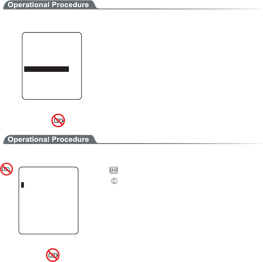
Chapter 3 System menu
3-16
3-8-2 Clock
This function is to confirm the current time, and set up the time.
In addition to Manual Setup, setting up the clock via the "Server Setting" to adjust the time of the terminal to that
of the host computer is possible, when the DHCP function is enabled.
■Current Time
1. From the System Setup Menu, select "2:Clock"
6KOG
/CPWCNUGVVKPI
5GTXGTUGVVKPI
/QP
Current Time is displayed.
Select the item to setup.
・ Manual setting
・ Server setting
■Manual setting
1. Input the time data.
/CPWCN5GVVKPI
Press the key, and confirm the time.
Press the key to cancel setting and return to current
time.
■Server setting
Server setting, confirm the following beforehand.
・ WLAN communication setup(SSID, Security etc.) between the terminal and the access point is
correctly setup.
・ The power of the access point and the host computer is ON.
・ The access point and the host computer is correctly setup and connected.
・ The access point is normally operating.
・ DHCP server of the "WebGlider-X" Network manager is running.
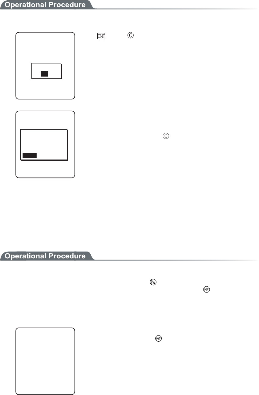
3-8 System Setup Menu
3-17
1. Receiving the time data from the DHCP of "WebGlider-X" Network Manager.
5GTXGTUGVVKPI
&*%25GTXGT
%QPPGEVVQ
%QORNGVGF
1-
Press key or key to return to check the current time.
%QPPGEVVQ
6KOGCESWKUKVKQP
HCKNGF
4GVT[!
5GTXGTUGVVKPI
4'64;%#0%'.
When receiving is failed, the screen on the left is displayed.
[Select RETRY], to receive the Time data from the server again.
Select [CANCEL], or Press the key to cancel setup and return
to Current time.
3-8-3 Resume (resume function)
The GTX-100 supports a resume function. The resume function can be enabled through the System menu and if
selected, the next time the key is pressed on the GTX-100, the resume function will be used. Resume mode ON
after the GTX-100 is powered OFF, the next time the key is pressed, it will resume operation where it was just
before the power was turned OFF. For details of the resume function, please refer to the "1-10 Resume func-
tion"(P.1-26).
●Resume mode ON
After the GTX-100 is powered OFF, the next time the key is pressed, it will resume operation
where it was just before the power was turned OFF. (Power ON, pressing the
key while pressing
the scan key to cancel resume mode)
●Resume Fail
4GUWOGHCKN
JKVCP[MG[
5VCTVWUWCN
Resume setup will fail when the power OFF by removing the bat-
tery and without pressing the key.
Chapter 3 System menu
3-18
●Resume mode OFF
After the GTX-100 is powered OFF, the next time the key is
pressed, it will begin operation from the start.
When the application is setup to " Auto Execute", the assigned appli-
cation will startup.
In the case where the battery is disconnected while the power is ON,
the operation will begin from the start regardless of the resume
mode settings. In order to enable the resume function, turn ON/OFF
the power by pressing the key. However, even when the resume
function is enabled, the process will be performed from the begin-
ning if the Network DHCP setting “■Startup type” (P.3-37) is set to
“Application boot” or “System menu boot.”
3-8-4 Password
The password to avoid unnecessary running on of the System menu will be setup. By setting a password, the
third person other than the system administrator unable to confirm or modify the setup contents.
2CUUYQTF!
In case a password is setup, the password confirmation will be performed at the
time of starting up of the System menu. The System menu will not start up unless
the password is entered.
However, when the power OFF by pressing the
key, with resume function
enabled, while System menu is displayed, the password check will not performed
when the terminal will restart from the System menu.
Be sure to take notes of the encryption number, and keep it so that
you may not forget it. In case you forget the number, please contact
our sales department.
1. From the System setup, select "4:Password".
2CUUYQTF
%NGCT
5GV
Select the item to setup.
・ Set
・ Clear
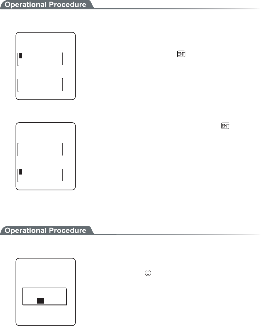
3-8 System Setup Menu
3-19
■Password setting
1. Input a new password.
0GYRCUUYQTF
2CUUYQTFUGVVKPI
0GYRCUUYQTFCICKP
Password should be alphanumeric characters from 4 to 30, Up-
per-case character/Lower-case character are distinguished.
Input a new password, then, press the key.
2. Input the password again.
0GYRCUUYQTF
2CUUYQTFUGVVKPI
CDEF
0GYRCUUYQTFCICKP
After the password is entered, confirm by pressing the
key.
■Clearing a Password
1. From the confirmation dialog, select[Yes].
2CUUYQTFENGCT
2CUUYQTFENGCT!
;'501
The setup password is erased.
Select [No], or press the key, and clear to stop.
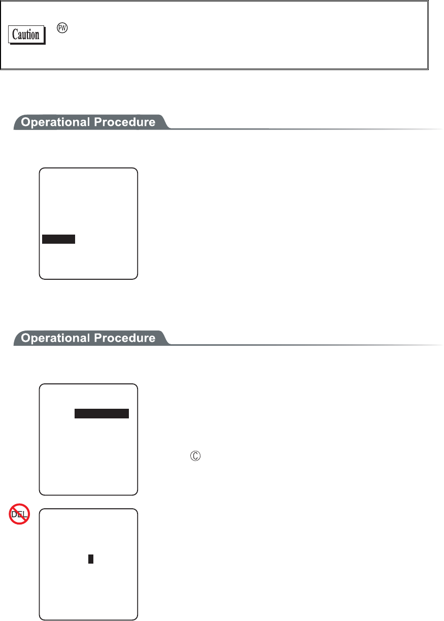
Chapter 3 System menu
3-20
3-8-5 Auto wake up
Auto wake up is a function to start up the terminal automatically according to the preset schedule. By combining
Auto wake up and DHCP Execute running on, which allow the application and the master file automatically up-
dated before starting operation.
Auto wake up function is enabled only when the terminal is closed by the
key. The terminal will not start up, even at the preset Auto wake up
time, when after replacing the battery or forced termination due to a low
battery.
■Schedule confirmation
1. From the System setup, select "5:Auto wake up".
2TGUGPV5EJGFWNG
GXGT[YGGM
QP/QPFC[
%NGCT
CV
5GV
Currently setup schedule is displayed.
Select the item to setup.
・ Set
・ Clear
■Schedule setting
1. Select Schedule accrual cycle.
5EJGFWNGUGVVKPI
GXGT[OQPVJ
GXGT[YGGM
%[ENG=GXGT[FC[?
Selected from among every day (time is specified), every week
(week and time are specified), and every month (date and time are
specified). Date is set from "01" to "31", time for 24 hours style.
When setting has completed, then return to Schedule confirma-
tion.
Press the key to stop setting and return to Schedule confirma-
tion.
%[ENGᵘGXGT[OQPVJᵚ
5EJGFWNGUGVVKPI
&CVGᵘᵚ
6KOGᵘᵚ
Input the time in 24 hour-style (00:00 to 23:59).
Thus complete the setup, and return to Schedule confirmation.
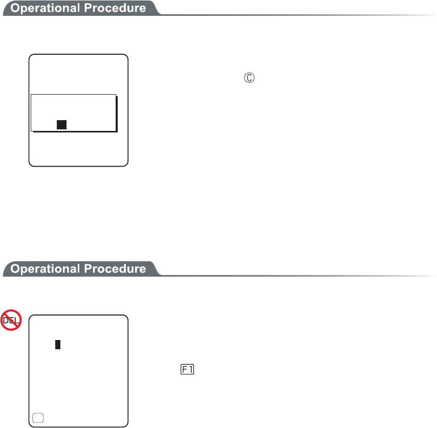
3-8 System Setup Menu
3-21
■Schedule Clearing
1. From the confirmation dialog, select[Yes].
5EJGFWNGENGCT
9QWNF[QWNKMGVQ
ENGCTUEJGFWNG!
;'501
The setup Schedule is erased.
Select [No], or Press the key to stop clearing.
3-8-6 Auto power off
Auto power off is a function to make the power OFF automatically when there is no operation performed for a
certain period.
1. From the System setup, then select "6:Auto power off".
ᵘᵚ5GE
#WVQRQYGTQHH
ǽ)WKFCPEG
(
Input the Auto power off time.
The time allowed to setup is from 0060 seconds to 3600 seconds. In
addition, when set to 0000 seconds, the Auto power off is disabled.
Press the key, and, setup value related guidance is displayed.
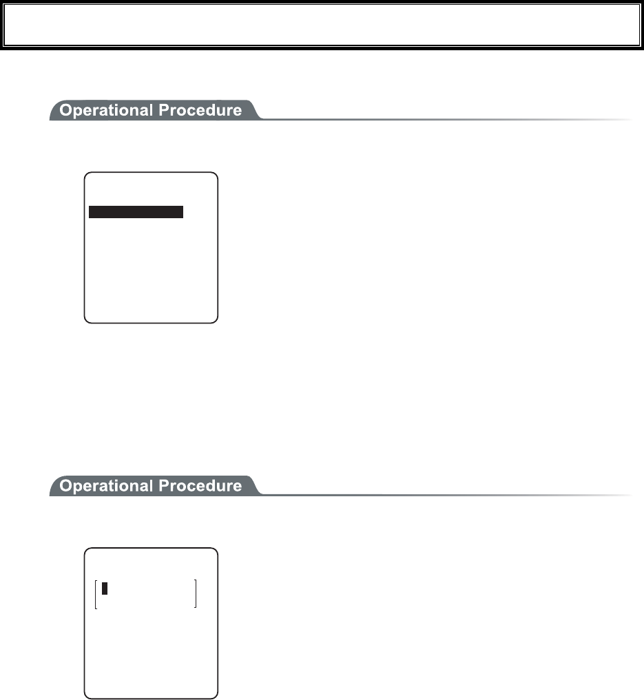
Chapter 3 System menu
3-22
3-9 WLAN Menu
Wireless LAN related setup is performed.
1. From the System menu, select "2:WLAN".
4QCOKPINGXGN
9.#0
&Q\GOQFG
5GEWTKV[
#FXCPEGF
/#%CFFTGUU
55+&
Select the item to setup.
・ SSID
・ Roaming level
・ Doze mode
・ Security
・ Advanced
・ MAC address
3-9-1 SSID
SSID setup. The characters allowed to enter are single-byte alphanumeric characters whose number should be up
to 32, and Upper-case character/Lower-case character is distinguished.
When DHCP function is enabled, automatic setup is possible, but this is not recommended as security problems
may occur.
1. From the WLAN, select "1:SSID".
)6:
55+&
Input the SSID.
SSID should be in alphanumeric character up to 32 charac-
ters, and Upper-case character/Lower-case character distin-
guished.
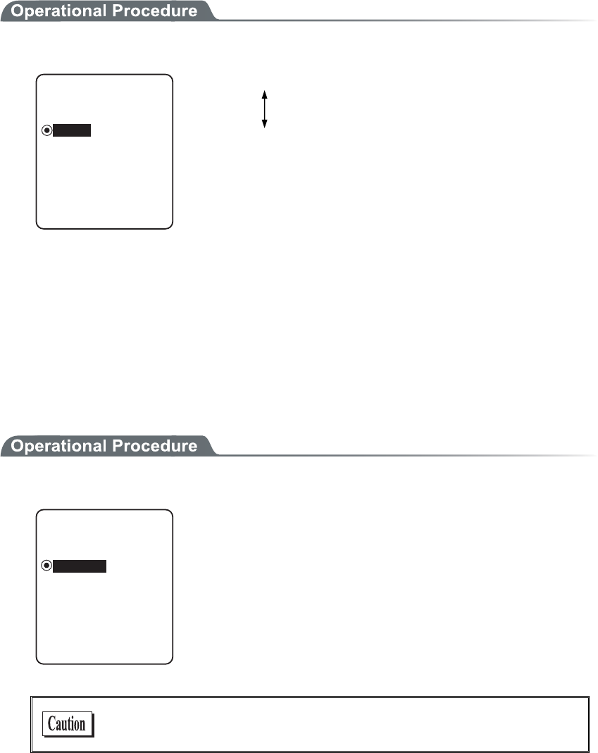
3-9 WLAN Menu
3-23
3-9-2 Roaming level
Roaming means a function, which switches the access point by choosing the access point with stronger radio
signal when the terminal moves. The roaming level created as the judgment value to judge whether to perform
the switching. When DHCP function is enabled, automatic setting is possible. The roaming is performs only be-
tween the access points with identical SSID.
1. From the WLAN, select "2:Roaming level".
ǽ0QTOCN
4QCOKPINGXGN
Dz(CUV
Dz5NQY
Slow roaming is difficult to perform.
Normal
Fast roaming is easy to perform.
3-9-3 Doze mode
The time during which the WLAN switches into Doze mode after transmission finished.
The shorter this time is the less consumption of the battery pack becomes, however, the responsiveness of
WLAN decreases.
When DHCP function is enabled, automatic setting is also possible. The WLAN response time varies according
to the beacon cycle and DTIM setting of the access point.
For details about the beacon and DTIM, please refer to the access point's Manual.
1. From the WLAN, select "3:Doze mode".
ǽUGEQPF
Dz3WKEM
&Q\GOQFG
Dz0QPG
Select the item to setup.
In the case to have the DHCP function enabled, please refer to the
"WebGlider-X" Manual for details

Chapter 3 System menu
3-24
3-9-4 Security
Security related setting of WLAN is performed.
1. From the WLAN menu, select "4:Security".
5GEWTKV[
#VVGPVKQP
#WVJGPVKECVKQP
'PET[RVKQP
Select the item to setup.
・ Encryption
・ Authentication
・ Attention
■Encryption
1. Select the item to setup.
'PET[RVKQP
25-6-+2%%/2
9'2
/GVJQF
・ Method
・ WEP
・ PSK(TKIP/CCMP)
●Method
1. Select the item to setup.
ǽ&KUCDNGF
Dz9'2DKV
/GVJQF
Dz9'2DKV
Dz6-+2
Dz%%/2#'5
Select the item to setup.
In the Authentication Method using "EAP"(P.3-28), communication
cannot be performed when "Disabled", "WEP (40bit)" or "WEP
(128bit)" is setup.
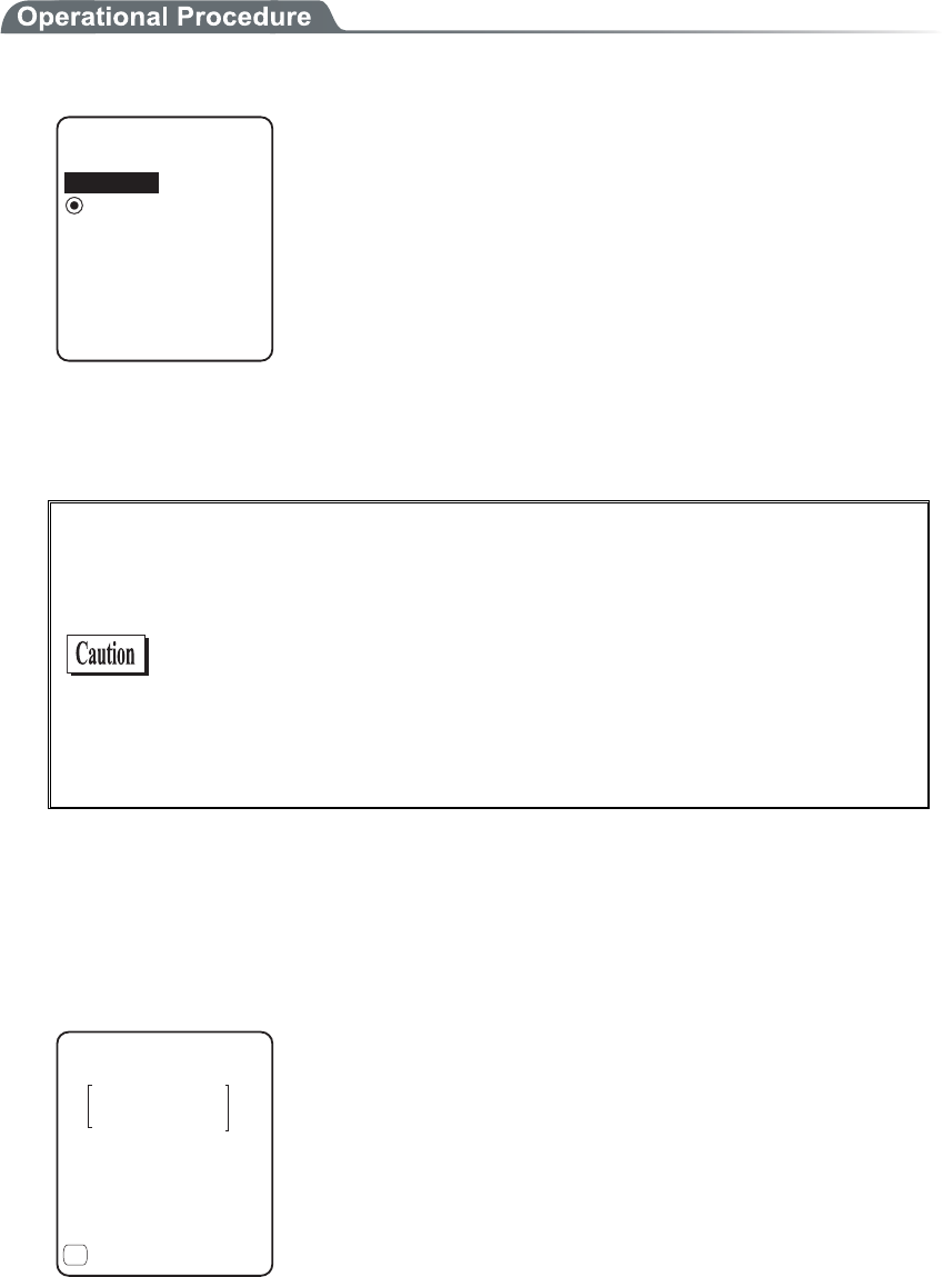
3-9 WLAN Menu
3-25
●WEP(Wired Equivalent Privacy)
Since IEEE802.11b/g is a general wireless standard, it may be easily intercepted by a third person.
The danger of data being intercepted between an access point and a terminal (GTX-100) is avoidable
by using WEP, which is the standard of encryption of wireless communication.
GTX-100 is compliant with two kinds of WEP keys (common key), "40 bits (also called 64 bits)" and
"128 bits."
1. Select the item to setup.
6Z-G[+&
ǽ-';
9'2
Dz-';
Dz-';
Dz-';
-G[/QFKH[
From the sub menu, select the item to setup.
・TxKey_ID
Select the ID used for transmission from KEY1- KEY4 set in the next paragraph " KEY setup."
This becomes effective if the WEP settings are set to other than "Disabled."
Communication is possible only if the contents of both the WEP key
of selected Tx KEY_ID and the access point WEP key are the same,
and if the contents of both the Transmit KEY WEP key set on the
access point and the terminal's WEP key are the same. For example,
when the Tx KEY_ID of a terminal is set to "2," the contents of the
terminal WEP key 2 and the contents of the access point WEP key 2
need to be the same. On the other hand, when an access point
Transmit key is set to "3," the contents of the access point WEP key 3
and the contents of the terminal WEP key 3 need to be the same.
・KEY Setup
You need to set the contents of each WEP key (1, 2, 3, 4).
You can set a WEP key in either HEX string format (0 to 9 and A to F) or ASCII string format. Use
the [F1] key to toggle between these formats. If the trigger key is pressed, the setup can be done by
scanning a barcode.
・ HEX string (default)
-G[OQFKH[
#5%++
(
When “40 bits” is selected, the key length is fixed at 10 characters.
When “128 bits” is selected, the key length is fixed at 26 characters.
The number of characters that are actually input is always 26. There-
fore, when “40 bits” is selected, only the first 10 characters of the 26
characters are used.
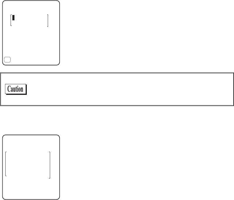
Chapter 3 System menu
3-26
・ ASCII string
-G[OQFKH[
*':
(
When “40 bits” is selected, the key length is fixed at 5 characters.
When “128 bits” is selected, the key length is fixed at 13 characters.
The number of characters that are actually input is always 13. There-
fore, when “40 bits” is selected, only the first 5 characters of the 13
characters are used. Blank is recognized as a space (0 × 20).
Each WEP key setup can be overwritten but cannot be edited.
On entering the KEY setup screen, it displays "00000." for security
purposes.
●PSK(TKIP/CCMP)
25-6-+2%%/2
If you select PSK (TKIP/CCMP) as an encryption mechanism, you
need to enter an encryption key. Specify the same encryption key as
the access point.
When setting an encryption key in ASCII format, enter 8 to 63 char-
acters. When setting an encryption key in hexadecimal format, enter
64 characters.
When using PSK (TKIP/CCMP), specify “Open” as the authentica-
tion method (P.3-28).

3-9 WLAN Menu
3-27
Security Function
The GTX-100 incorporates WPA and WPA2 as the WLAN security function.
■WPA (WPA-PSK) and WPA2 (WPA2-PSK)
⋅ WPA (Wi-Fi Protected Access)
WPA is a security standard publicized in December 2002 by the Wi-Fi Alliance, an industry
organization which verifies the interconnectivity of wireless LANs. WPA was developed as a
provisional subset of the IEEE802.11i standard until IEEE802.11i is popularized.
IEEE802.1X (EAP) is employed as an authentication method and TKIP, which improved the
drawbacks of WEP, as an encryption mechanism.
⋅ WPA2 and IEEE802.11i
IEEE802.11i is a wireless LAN security standard established by IEEE in June 2004. This
standard uses IEEE802.1X (EAP) and the AES encryption mechanism.
WPA2 conforms to IEEE802.11i, in contrast to WPA, which was a temporary standard until
IEEE802.11i is established.
⋅ PSK
PSK is an abbreviation of “Pre-Shared Key.” You need to set the same encryption key to the
access point and the terminal before you set up a wireless connection between them. The en-
cryption key must be managed carefully to prevent any possible leakage to any third party. In
this sense, the key set for WEP is also a PSK.
⋅ WPA-PSK and WPA2-PSK
WPA and WPA2 support a PSK mechanism as a simplified authentication method, because
these standards require infrastructural cost and technology, such as electronic certificates and
RADIUS servers to implement IEEE802.1X (EAP) authentication.
The PSK mechanism performs simplified authentication by setting on the terminal the same
Pre-Shared Key (PSK) as the access point and communicates with the access point using the
specified encryption mechanism (TKIP/CCMP (AES)). This mechanism does not use the
PSK directly as an encryption key. Rather, it generates a temporary key using random num-
bers every time a connection is established between an access point and the terminal or at
regular intervals. This process requires an additional time,” causing a delay of few seconds at
every wireless connection with an access point when compared with “no encryption” or
“WEP mechanism” configurations.
■Encryption scheme
The GTX-100 uses an encryption scheme as described below:
⋅ TKIP
TKIP is part of the IEEE802.11i wireless LAN encryption standard and stands for “Temporal
Key Integrity Protocol,” an encryption protocol which uses temporary keys. This function
overcomes the vulnerability of WEP while utilizing the same encryption algorithm RC4 as is
used in WEP. Instead of directly encrypting a temporary key using RC4, TKIP performs the
key-mixing procedure in two phases to encrypt each packet using a different key.
⋅ AES
AES is an encryption standard developed for use by the U.S. government and uses an algo-
rithm called “Rijndael.” While AES satisfies two important requirements, safety and speed, it
requires new hardware-based processing because it uses a completely different encryption
algorithm from WEP or TKIP.
⋅ CCMP
CCMP (Counter mode with CBC-MAC Protocol) is a tamper detection protocol used in
AES. CCMP detects tamper events using the CBC-MAC (Cipher-Block Message Authenti-
cation Code) mechanism. WPA2 (IEEE802.11i) requires the use of the CCMP mechanism.
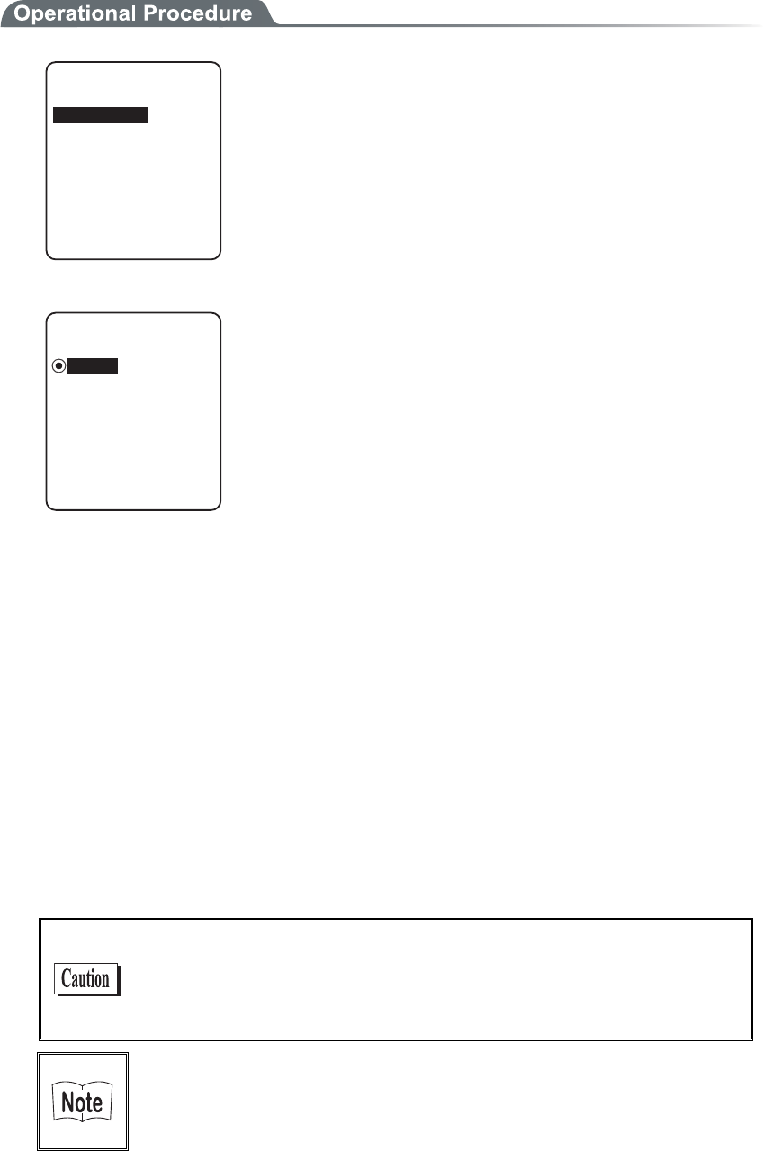
Chapter 3 System menu
3-28
■Authentication
/GVJQF
#WVJGPVKECVKQP
ǽǽǽǽǽǽǽǽǽǽ
'#2OQFKH[
Select the item to setup.
●Method
ǽ1RGP
#WVJGPVKECVKQP
Dz5JCTGF
Dz'#2
・ Open
"Open Authentication" system.
If an authentication request frame from a terminal (GTX-100)
is received, an access point will reply with an authentication
response frame, which will permit data communications.
When WEP is valid, authentication is possible but data com-
munications cannot be performed if both WEP keys do not
match.
・ Shared
"Shared Key Authentication" system.
If a terminal performs an authentication request, an access
point will transmit a non-encrypted identity request authentica-
tion text character string (hereinafter called as "challenge
code"). Then, the terminal replies a challenge code encrypted
using the WEP key. The access point decrypts the challenge
code via the WEP key and checks to see if it is the same as the
transmitted challenge code and if the same, permits authentica-
tion.
・ EAP
"EAP"(IEEE802.1X) Authentication system.
If this authentication method is used, Certificate, Private key,
user information setting etc. is needed. There is a limitation
also in the environment (Certification Authority (CA), authen-
tication (RADIUS) server etc.) that can be used. Therefore,
when using the "EAP" authentication method, please contact
our sales department.
If the challenge code before and after encryption is intercepted by a
third person, the WEP key is easily determined. The "Shared Key
Authentication" system thus creates a security weak point and
should not be used whenever possible.
Some access points do not disclose their authentication type. In this
case, please try "Open Authentication," and if connection is impos-
sible, try "Shared Key Authentication."
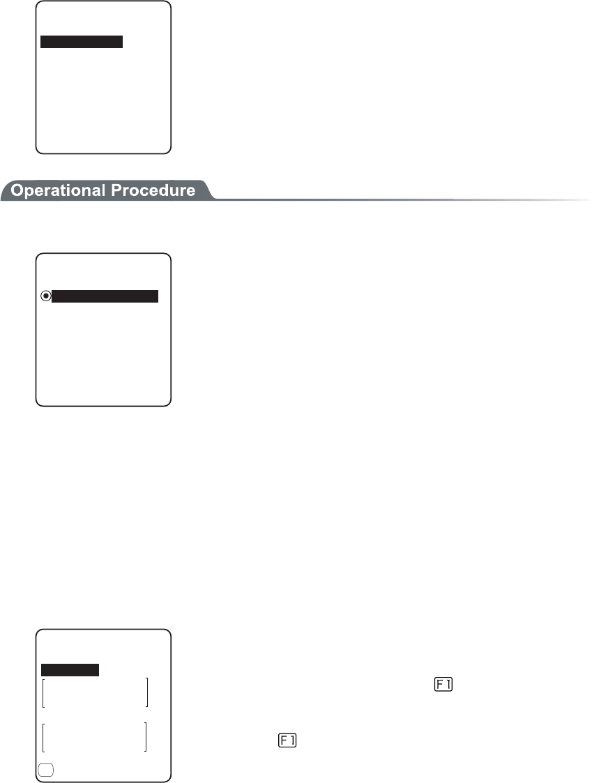
3-9 WLAN Menu
3-29
●EAP setup
When using the EAP (IEEE802.1X) authentication, the required items are set.
After setup, perform the "wireless/ping test" (P.3-88), and confirm that the communication by EAP
authentication is enabled.
'#2OQFG
'#2OQFKH[
%GTVKHKECVG
7UGT+PHQ
#FXCPFGF
2TKXCVGMG[
Select the item to setup.
1. Select the mode.
'#2OQFG
ǽǽǽǽǽǽǽǽǽǽ
Dz'#22'#2/5%*#2X
ǽ'#26.5
・ EAP-TLS
Server certificate for server authentication, and client certifi-
cate for client authentication are the necessary authentication
method.
The necessary items for setting is as follows.
・CA root certificate
・Client certificate
・Private key
・User name
・ EAP-PEAP-MSCHAPv2
Server certificate for server authentication, while user name,
password for client authentication are the necessary authenti-
cation Method.
The necessary items for setting is as follows.
・CA root Certificate
・User name
・Password
2. Certificate file is setup.
Each certificate file is received via FTP (P.3-38) or Bluetooth (P.3-63).
%#TQQV
%GTVKHKECVG
ǽǽǽǽǽǽǽǽǽǽ
%NKGPV
ǽ%NGCTGPVT[
(
・ CA root certificate(file)
The CA root certificate issued by the server certificate agency
required for server authentication. This does not support the
layered chain of certificate. Press the key to clear.
・ Client certificate(file)
Client certificate is necessary for client authentication.
Press the
key to clear.
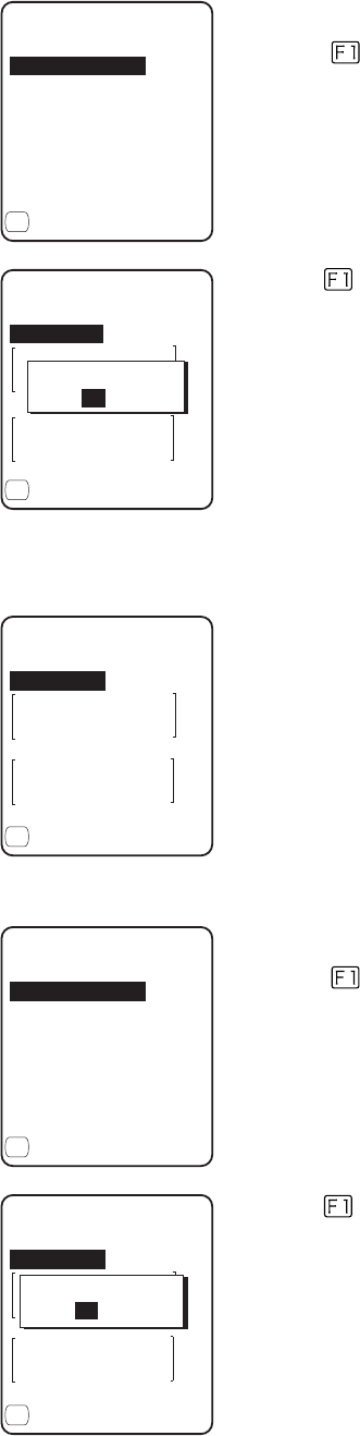
Chapter 3 System menu
3-30
4116%'46%'4
4GHGTGPEGVQHKNG
ǽǽǽǽǽǽǽǽǽǽ
24+8#6'-';
%.+'06%'46%'4
ǽ2TQRGTV[
(
Select from received files.
(Press the key to refer the file Properties.)
%#TQQV
%GTVKHKECVG
ǽǽǽǽǽǽǽǽǽǽ
%NKGPV
ǽ%NGCTGPVT[
(
+UENGCTGPVT[!
;'501
Press the
key to clear the setup contents.
3. Private key setting.
Private key(file) is received via FTP (P.3-38), or Bluetooth (P.3-63).
(KNG
2TKXCVGMG[
ǽǽǽǽǽǽǽǽǽǽ
2CUUYQTF
ǽ%NGCTGPVT[
(
・File
Private key is in contrast to the client Open key included in the
client certificate. This private key is very important for security
reason. Encryption should be made on the private key file, and
manage so that the password is not known to the third person.
・Password
Single-byte alphanumeric characters from 0 to 31 characters
Upper-case character/Lower-case characters distinguished for
setup.
For security purpose, the input password after entered is
converted and displayed as the hidden character (*).
4116%'46%'4
4GHGTGPEGVQHKNG
ǽǽǽǽǽǽǽǽǽǽ
24+8#6'-';
%.+'06%'46%'4
ǽ2TQRGTV[
(
Select from the received files.
(Press the
key to refer the file properties.)
(KNG
2TKXCVGMG[
ǽǽǽǽǽǽǽǽǽǽ
2CUUYQTF
ǽ%NGCTGPVT[
(
+UENGCTGPVT[!
;'501
Press the
key to clear the setup contents.
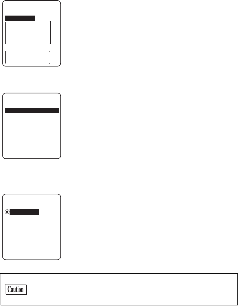
3-9 WLAN Menu
3-31
4. Set up user information.
7UGT0COG
7UGT+PHQ
2CUUYQTF
・ User Name
User name is used for authentication.
From 62 single-byte alphanumeric characters, it is set by dis-
tinguishing Upper-case character/Lower-case character.
・ Password
Password is used for authentication
From 0 to 31 single-byte alphanumeric characters, it is set by
distinguishing Upper-case character/Lower-case character. For
security purpose, the entered password is displayed being con-
verted as a hidden character" *".
5. Setup the detail. This setup usually is not modified.
#WVJGPVKECVKQP6KOG
'#2#FXCPEGF
ᵚ
ᵘUGE
・At starting up authentication Time out
When WLAN start up, it waits the authentication to complete
up to the second setup here.
possible setup value :15 to 120 seconds
■Attention
ǽ&KURNC[
#VVGPVKQP
ǽǽǽǽǽǽǽǽǽǽ
Dz0QV&KURNC[
The default is set to "Display".
In the case when the terminal is started up without WLAN security
setting, "WLAN Security setting" attention screen is displayed. By
setting this attention to OFF, this message is not displayed at starting
up even when WLAN security setting is disabled.
It is not recommended to set this Attention to setting to OFF, for
security reason. Be sure to perform security setting when using
WLAN communication.

Chapter 3 System menu
3-32
3-9-5 Advanced
WLAN communication Advanced setting
1. From the WLAN, select "5:Advanced".
=D#WVQ?
#FXCPEGF
465A6JTGUJQNF
=?$[VGU
4CVG%QPVTQN
Select the item to set.

3-9 WLAN Menu
3-33
●Transmission speed
Set the transmission speed. Automatic setup is possible when the DHCP function (P.3-36) is enabled.
Any of the settings shown in the table below can be selected. Please keep in mind that if you fix at a
higher communication speed, the transmission range will become shorter.
Connectivity depending on
speed setting on access point
side*1
Speed
setting Description
11b/g
Both
11b
Only
11g
Only
11b Auto
(default)
The transmission speed is automatically varied as ap-
propriate, depending on the distance between the ter-
minal and the access point. The speed is within the
range defined in IEEE802.11b (11, 5.5, 2 or 1 Mbps).
○ ○ ×
11bg Auto
The transmission speed is automatically varied as ap-
propriate, depending on the distance between the ter-
minal and the access point.
△ ○ ◎
11g Auto
The transmission speed is automatically varied as ap-
propriate, depending on the distance between the ter-
minal and the access point. The speed is within the
range defined in IEEE802.11g (54, 48, 36, 24, 18,
12, 9 or 6 Mbps).
△ ○ ◎
11g 6 or
9M
The transmission speed is varied between 9 Mbps and
6 Mbps automatically according to the distance be-
tween the terminal and the access point.
△ ○ ◎
1M The transmission speed is fixed at 1 Mbps. ○ ○ ×
2M The transmission speed is fixed at 2 Mbps. ○ ○ ×
1 or 2M The transmission speed is automatically varied be-
tween 1 Mbps and 2 Mbps only. ○ ○ ×
5.5M The transmission speed is fixed at 5.5 Mbps. ○ ○ ×
11M The transmission speed is fixed at 11 Mbps. ○ ○ ×
*1: Speed setting on the access point side and connectivity
◎: Connection is possible. Priority is given to the 11g speed, and high-speed communica-
tions are possible.
○: Connection is possible. Communications are performed at the 11b speed.
△: Connection is possible. The throughput will be reduced due to 11b/g negotiation.
×: Connection is not possible.
●RTS Threshold
This determines whether an RTS packet is transmitted before transmission of a data packet. When the
size of a data packet is larger than the set value, an RTS packet is transmitted, and RTS-CTS control is
performed. When a large number of terminals are connected to the same access point, or terminals
cannot detect each other because they are dispersed remotely even if detection of an access point is
possible, RTS-CTS control becomes effective. Although RTS-CTS control is effective in this case, the
throughput reduces. Usually set it to the default value (2347 bytes).
・ Setting range:0 to 2347 bytes

Chapter 3 System menu
3-34
3-9-6 MAC address
MAC address (hardware unique address) is displayed. MAC address cannot be changed.
1. From the WLAN, select "6:MAC address".
ᵘ%$&ᵚ
/#%CFFTGUU
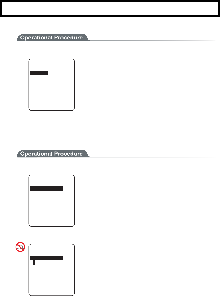
3-10 Network Menu
3-35
3-10 Network Menu
Network related setting such as TCP/IP.
1. From the System menu, select "3:Network".
0GVYQTM
(62
&05
&*%2
50/2
6%2+2
Select the item to setup.
・ TCP/IP
・ DHCP
・ FTP
・ DNS
・ SNMP
3-10-1 TCP/IP
Set an IP address and other details for TCP/IP communications. Automatic setup is possible when the DHCP
function is enabled.
1. From the Network, select "1:TCP/IP".
ᵘᵚ
6%2+2
0GV/CUM
ᵘᵚ
)CVGYC[
ᵘᵚ
/67
ᵘᵚ1EVGV
+2#FFTGUU
Current setting contents are displayed.
Select the item to setup.
2. Input the address.
ᵘᵚ
6%2+2
0GV/CUM
ᵘᵚ
)CVGYC[
ᵘᵚ
/67
ᵘᵚ1EVGV
+2#FFTGUU
Input the number from 000 to 255 to the field segmented by
the period (example:192.168.254.254).
* The Display is an example of "IP address". "NetMask" and
"Gateway" is operated in the same way.
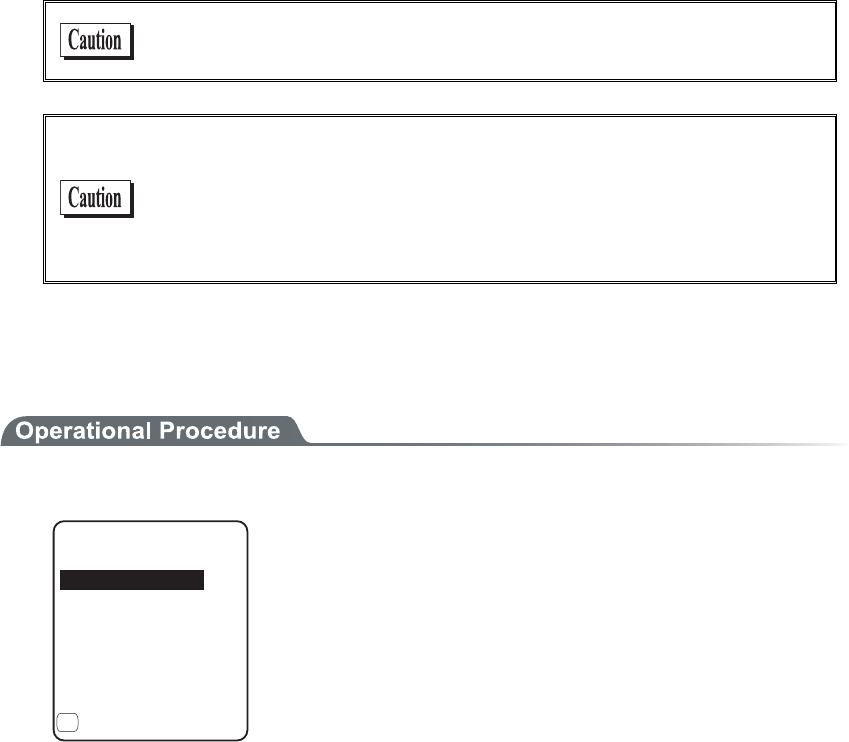
Chapter 3 System menu
3-36
・IP address
Set the IP address assigned by the network administrator. Set a unique IP address to each of the
GTX-100 terminals connected to the same network.
・NetMask (Subnet mask)
Set the subnet mask assigned by the network administrator. Since a subnet mask specifies which
network you belong to, it should set up along with the IP address.
・Gateway (Default gateway)
Set the address of the default gateway. Setup is required when connecting to a different network
through a router.
・ MTU
The maximum length of IP packet. 1500 octets (bytes) is common for Ethernet. In such cases as
being used over the routers, this value should be modified according to the communication me-
dia. Please ask the network administrator about the value settings for different items.
When the status of the IP address is [000.000.000.000],the WLAN
communication is unable to be executed.
Please ask the network administrator about the value settings for
different items.
From the "Startup type" of DHCP setting (P.3-37), in case either
"Application boot" or "System menu boot" is selected, the value
except for MTU can only be confirmed but unable to be modified.
3-10-2 DHCP
Set the DHCP client function that is used for automatic setup of TCP/IP and various set items.
1. From the Network menu, select "2:DHCP."
&*%2
5GTXGTRQTV
ᵘᵚ
7RFCVGRTQVGEV
ǽ'ZGEWVG
5VCTVWRV[RG
(
Select the item to setup.
・ Startup type
・ Update protect
・ Server port
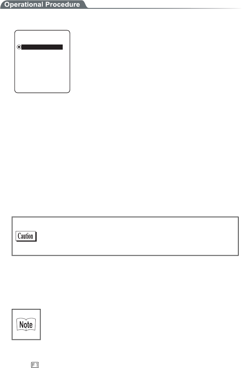
3-10 Network Menu
3-37
■Startup type
1. Select the item to setup.
5VCTVWRV[RG
Dz5[UVGOOGPWDQQV
Dz#RRNKECVKQPDQQV
ǽ&KUCDNGF
・ Disabled (Factory setup)
DHCP is not executed when the terminal started up.
・ Application boot
DHCP is executed before the application is executed.
The application file is selected from <System
menu>[1:System], and then[2:Auto execute], DHCP function
is executed before application , after the terminal started up. In
addition, when the application is started up from <File menu>,
DHCP is not executed.
・ System menu boot
DHCP is executed before System menu is started up. The Sys-
tem menu is selected from <System menu>[1:System], and
then[1:Auto execute], DHCP function is executed before Sys-
tem menu is started up , after the terminal started up.
■Update protect
Following information unique to the terminal is setup so as not to be modified, before executing
DHCP function.
・ IP address
・ NetMask
・ Gateway
・ ID
In the case when the check is applied to IP address (IP address up-
date is prohibited), the IP address, which has set up at the terminal, is
not modified. Be sure to use confirming that the there is no host with
the same IP address on the Network.
■Server port number
DHCP server port is setup (Factory setup:08067).
If you do not execute the automatic setup, which is unique to the GTX-100, and want to use existing
server only to perform the assigning of IP address, the value is modified (the well known port is 67).
The port number of the DHCP server of "WebGlider-X" Network
manager is 08067 as default. This is to avoid a competition with
other DHCP servers working in the same network.
■Execute
Press the
key, and, DHCP is executed immediately, regardless of "Startup type"(P.3-37).
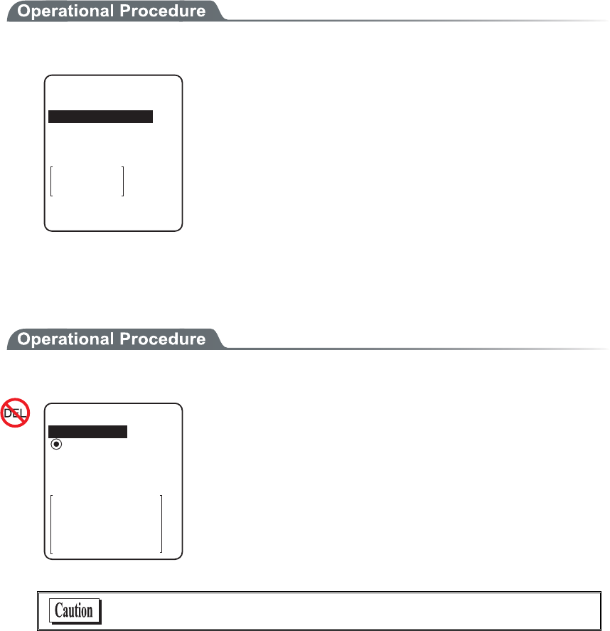
Chapter 3 System menu
3-38
3-10-3 FTP
Set up for using the FTP client function, as described below. Automatic setup is possible when the DHCP func-
tion is enabled.
1. From the Network, select "3:FTP".
(62
ᵘᵚ
7UGTPCOG
2CUUYQTF
5GTXGTCFFTGUU
#FXCPEGF
Select the item to setup.
・ Server address
・ User name
・ Password
・ Advanced
■Server address
Set up the host name for FTP server.
1. Select from either IP, or, URL.
5GTXGTCFFTGUU
5GVOGVJQF
ᵘᵚ
#FFTGUU
0COG
ǽ#FFTGUUDz0COG
・ Address
The IP address setup at 2:Address" is set as FTP server.
・ Name
The host specified at "3: Name" is set as FTP server.
The host name can not contain the space character.
When using "Name", please perform the DNS setup (P.3-41)."
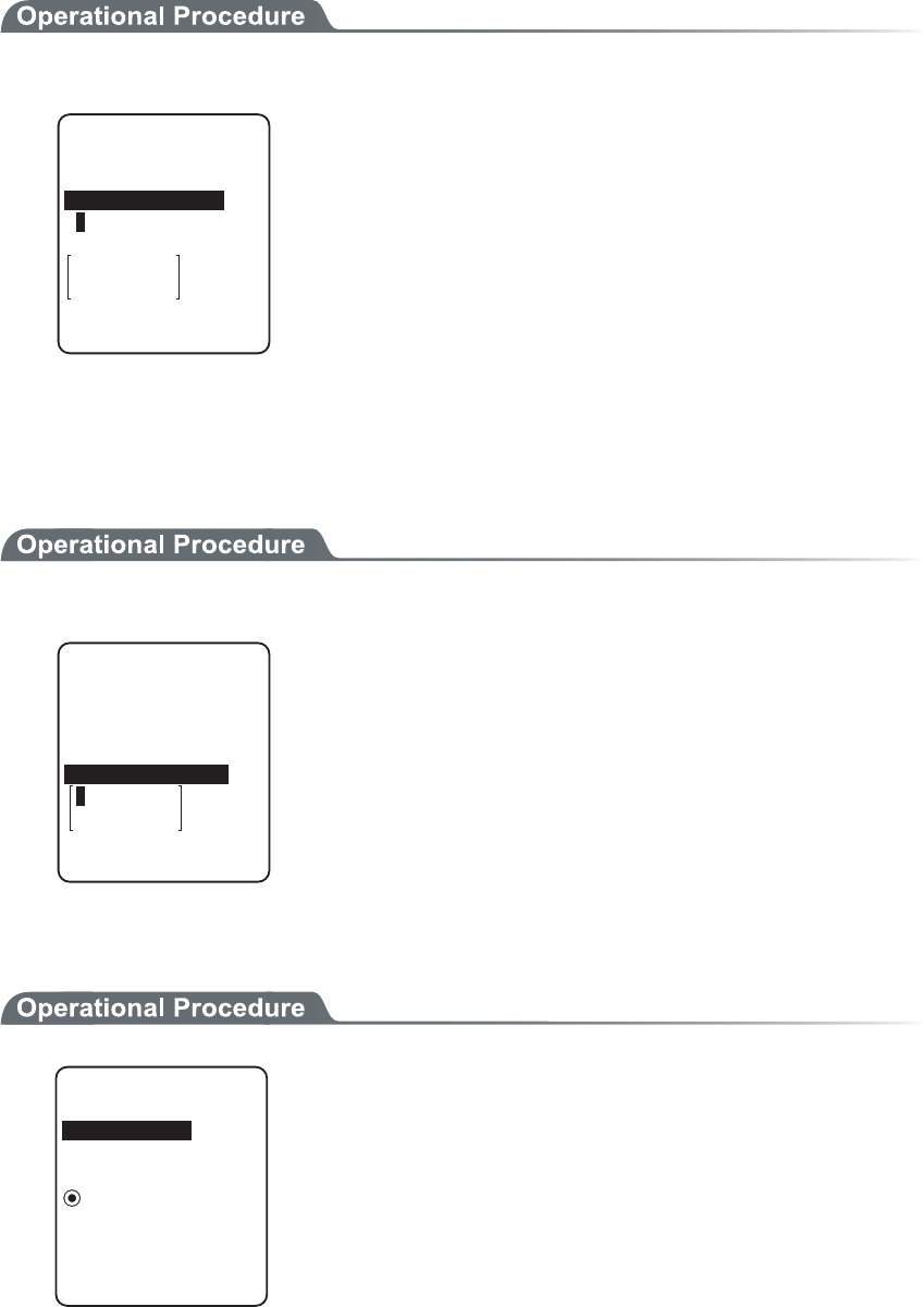
3-10 Network Menu
3-39
■User name
Specify the FTP server login user name using up to 18 alphanumeric characters, and up-
per-case/lower-case should be distinguished.
1. Input the User name.
(62
ᵘᵚ
7UGTPCOG
2CUUYQTF
5GTXGTCFFTGUU
#FXCPEGF
User name should not include the space.
■Password
Specify the FTP server login password using up to 20 alphanumeric characters, and up-
per-case/lower-case should be distinguished.
1. Input the Password.
(62
ᵘᵚ
7UGTPCOG
2CUUYQTF
5GTXGTCFFTGUU
#FXCPEGF
The Password is converted to a hidden character (*) and is
displayed for security purpose.
Password should not include the space.
■Advanced
=?
#FXCPEGF
/QFG
ǽ2CUUKXGDz#EVKXG
(QNFGT
5GTXGT2QTV
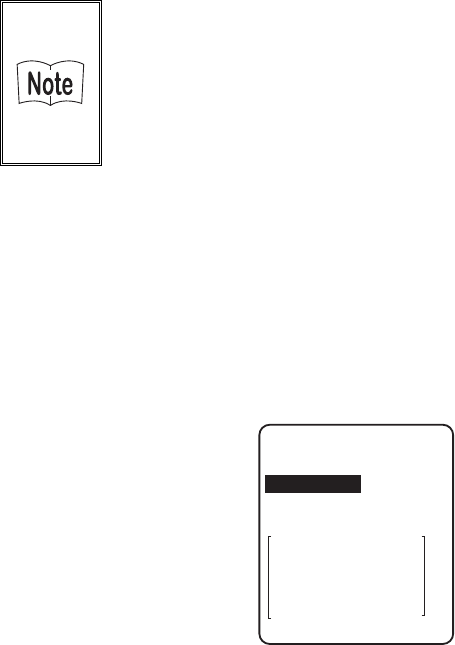
Chapter 3 System menu
3-40
●Server port
Specify FTP server control port number. The well-known port is 21.
●Mode
The default is Passive mode. If the FTP server does not support Passive mode, change it to the Active
mode.
There is a function to reject the connection from outside the Firewall
to inside in the Firewall set up. If this function is enabled, the FTP
communication cannot be performed in the Active mode. By using
Passive mode, the communication between the FTP server over the
Firewall.
●Folder
・Current
/(root)
In some FTP server, the User name folder is specified as root folder.
/(user name)
The folder in the root folder with the same as the user name of the FTP server is specified as the
current folder. If FTP function (file transmission or reception) is executed without setting the
user name, the error screen appears.
%WTTGPV
(QNFGT
5RGEKHKGF
ᵘ4QQVᵚ
/(Specified)
The relative path setup at the "specified folder" which is to be explained later becomes the cur-
rent folder.
・Specified
When selected "/(Specified)" in the folder above, the character string setup here are added to the
FTP method "CWD". As the setup character string communicates directly by FTP communica-
tion, please setup the corresponding character string to the server.
(Example) "dir1/dir2/dir3"
The specified folder cannot include the space.

3-10 Network Menu
3-41
3-10-4 DNS
Set the DNS server address, as described below. Automatic setup is possible when the DHCP function (P.3-36)
is enabled.
1. From the Network, select "4:DNS".
2TKOCT[
ᵘᵚ
&05
5GEQPFCT[
ᵘᵚ
#FXCPEGF
2. Select the item to setup.
●Primary
Set the IP address for the Primary server.
●Secondary
Set the IP address for the Secondary server.
●Advanced
・ Server port
Specify the control port number for the DNS server. The well-known port is 53.
・ Time out time
Setup range is from 1 to 99 seconds. Set the response packet waiting time.
・ Trial count
When 0 is set, only one packet is transmitted without RETRY.
・ Cache time
Setup range is from 0 to 9999 min. When 0 is setup, the cache function is disabled. The MAX
value allowed to enter to the cache table is 8. When the entered number is over the MAX value,
a new entry will be performed after discarding the old entry.
Chapter 3 System menu
3-42
3-10-5 SNMP
Make the various SNMP settings. Automatic setup is possible when the DHCP function (P.3-36) is enabled.
1. From the Network, select "5:SNMP".
%QOOWPKV[41PN[
50/2
6TCR
#FXCPEGF
%QOOWPKV[49
Select the item to setup.
・ Community(R/Only) setting
・ Community(R/W) Setup
・ Trap
・ Advanced
■Community(R/Only) setting
%QOOWPKV[PCOG
ᵘRWDNKEᵚ
%QOOWPKV[41PN[
/CPCIGT+2CFFTGUU
ᵘᵚ
1. Input the community name and the manager IP address.
●Community name
The operations permitted for a community name are read only. GET and GET-NEXT requests are
supported under a community name. When a SET request is sent using a community name, an authen-
tication trap is transmitted. A community name can be specified using a maximum of 16 alphanumeric
characters.
●Manager IP address
Set the SNMP manager's IP address, which permits the use of the community name set under the
"Community name" option. If "000.000.000.000" is set as the IP address, this community name is
permitted on all the SNMP managers.

3-10 Network Menu
3-43
■Community(R/W) Setup
%QOOWPKV[PCOG
ᵘRTKXCVGᵚ
%QOOWPKV[49
/CPCIGT+2CFFTGUU
ᵘᵚ
1. Input the community name and the manager IP address.
●Community name
The operations permitted for the community name are "Read-Write".
GET, GET-NEXT and SET request are supported under a community name. The community name
can be specified using a maximum of 16 alphanumeric characters.
●Manager IP address
Set the SNMP manager's IP address, which permits The use of the community name set under the
[community name]option. If "000.000.000.000" is set as the SNMP manager's IP address, this com-
munity name is permitted on all the SNMP managers.
■Trap setting
%QOOWPKV[PCOG
ᵘ9GNECVᵚ
6TCR
/CPCIGT+2CFFTGUU
ᵘᵚ
1. Input a community name and a manager IP address.
●Community name
Set a community name for the Trap. A community name can be specified using a maximum of 16 alphanu-
meric characters.
●Manager IP Address
Set the SNMP manager's IP address to which the Trap should be transmitted. Trap is not transmitted if
the IP address of "000.000.000.000" has been set.

Chapter 3 System menu
3-44
■Advanced
#WVJGPVKE6TCR
ǫ5GPF
#FXCPEGF
#IGPVRQTV
ᵘᵚ
6TCRRQTV
ᵘᵚ
6TCRTGVT[
ᵘᵚ
●Authentic. trap
Set the action of authentication trap to either "send" or "don't send" when access is recognized except
from the community name and SNMP manager's IP address set in "1: Community (R/Only)" and "2:
Community (R/W)." This Trap is sent to the SNMP manager, which is set in "2:Target address."
●Agent port
The port number to communicate with SNMP manager. The well-known port is 161.
●Trap port
The port number to transmit the Trap. The well-known port is 162.
●Trap retry
The number of times Trap transmission retrial.
■About SNMP
・ GTX-100 can be managed by using Our "WebGlider-X"(WBG-001W).
・ SNMP-PDU(Protocol Data Unit) conforms to SNMPv1.
・ GTX-100supports the management of the objects in the following MIB group.
[1.3.6.1.2.1.1] MIB2-System
[1.3.6.1.2.1.2] MIB2-Interfaces
[1.3.6.1.2.1.4] MIB2-IP
[1.3.6.1.2.1.5] MIB2-ICMP
[1.3.6.1.2.1.6] MIB2-TCP
[1.3.6.1.2.1.7] MIB2-UDP
[1.3.6.1.2.1.11] MIB2-SNMP
[1.3.6.1.4.1.12392] Welcat Enterprise MIB
Welcat Enterprise MIB is described by ASN.1 format.
Welcat Enterprise MIB is included in the optional "WebGlider-X". (About details, please con-
tact our sales department.)

3-10 Network Menu
3-45
●Supported Traps
Cold Start Cold Start Transmitted after MIB is initialized and the communications
starts. MIB is initialized when the GTX-100 has been turned ON using
the PW key. Note that MIB is not initialized when the GTX-100 has been
turned ON in the resume mode.
Warm Start Warm Start Transmitted when communication starts except Cold Start.*1
Link up Link up Transmitted when GTX-100 synchronizes with an access point.
However, a Link Up is not transmitted when the GTX-100 synchronizes
with an access point for the first time (When a Cold Start or a Warm
Start is transmitted). When the GTX-100 newly enters a service area of
an access point and synchronizes, or when it synchronizes with a new
access point while roaming, a Link Up is transmitted (in the same timing
as signal SIGRFU_INSYNC).
Link down Link down Transmitted when the communication ends. However, it is
not transmitted when the GTX-100 is outside the service area of an ac-
cess point.
Authentication Transmitted when a third person tries to access the GTX-100 with an in-
valid community. This authentication trap is sent to the IP address set
through the System menu "Trap Manager IP address" (P.3-43). However,
this is transmitted only when the value "send" is set through the System
menu "Illegal access Trap" (P.3-44).
*1 MIB is not initialized even if the " GTX-100 " setup corresponding to MIB (IP address, subnet
mask, default gateway, etc.) has been changed. In this case, a Warm Start is transmitted instead
of a Cold Start. When initializing MIB, restart the terminal.
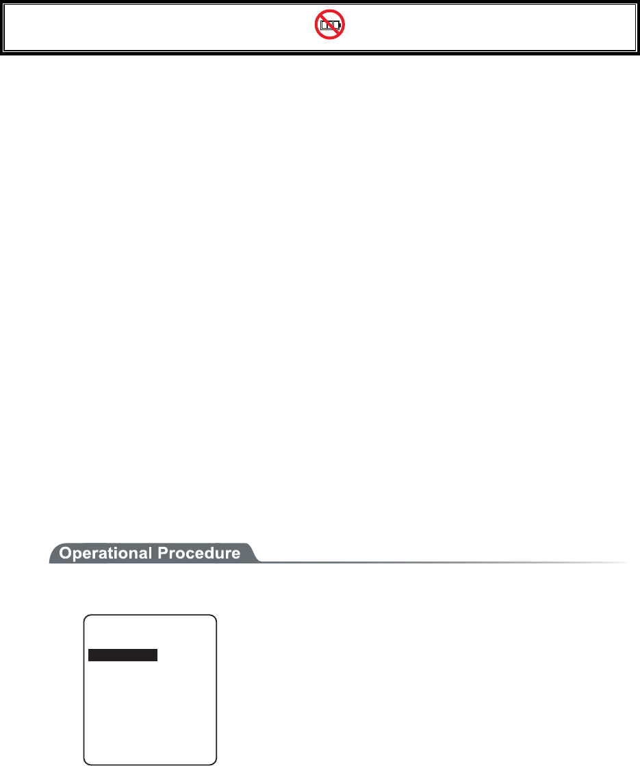
Chapter 3 System menu
3-46
3-11 Receiving Menu
Receiving files via WLAN, or Bluetooth. The GTX-100 can receive files transmitted from a host computer via
WLAN, or Bluetooth.
Before receiving a file, please check the following. The received files are all created in the F drive.
●WLAN
・ The communication setting (IP address, SSID, WEP etc.) between the GTX-100 and the Access point
are correctly set up.
・ The power of the access point and host computer is ON.
・ The access point and host computer is correctly setup or connected.
・ The access point is normally operating.
・ FTP server is running on the host computer.
・ FTP setup (host name, user name etc.) of GTX-100 is correctly setup.
●Bluetooth(Receiving side is the host computer)
・ The power of the host computer is ON.
・ The "BluePorter(WLF-001:optional)" on the host computer is started up.
・ The default device of GTX-100 is setup on the host computer at the receiving side. (only in the case
selected from the file list)
●Bluetooth(Receiving side is GTX-100)
・ Wait only is enabled.
・ The default device of GTX-100 is setup on the GTX-100 at the receiving side.
1. From the System menu, select "4:Receive".
&GXKEGV[RG
$NWGVQQVJ
9.#0
Select the device to use.
・ WLAN → 3.
・ Bluetooth → 2.
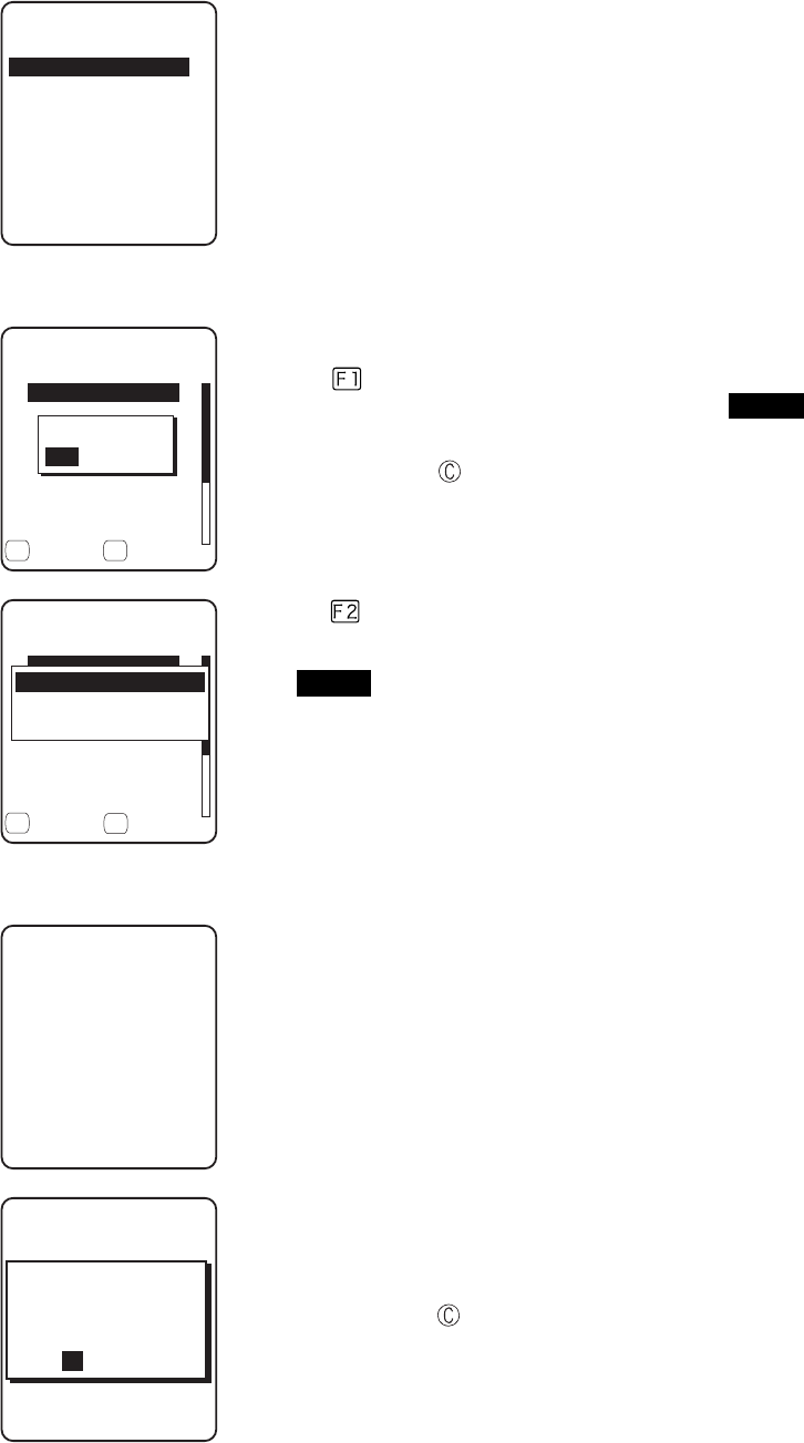
3-11 Receiving Menu
3-47
2. Selecting receiving method.
4GEGKXKPIOGVJQF
9CKV)6:
9CKV2%
5GNGEVHTQONKUV
Select "1: Select from list " to obtain the file list from the transmis-
sion side. The receiver side can select the file to receive from the list.
Select "2:Wait(PC)" or "3:Wait(GTX)”, then get into receiving wait-
ing status immediately. If it is the transmission from the host com-
puter select "2:Wait(PC)", when it is from GTX, Select
"3:Wait(GTX)". The receiving file depends on the transmission side.
・ 1:Select from the file list→ 3
・ 2:Wait(PC), 3:Wait(GTX)→ 4.
3. Acquire the file list, and select receiving file.
(KNGNKUV
ǫ9GNECVDOR
ǫ9IZDQWV
ǫKPFGZJVO
ǫZKVQWV
ǫ/CUVGTVZV
ǫ+VGO/CUVGTVZV
ǽ4GEGKXGǽ/GPW
ǫ$CTEQFGTGCFYCX
( (
4GEGKXGKV!
;'50Q
Apply checks to the check box of the receiving file.
Press the key, and Receiving Confirmation dialog is displayed.
In this case, if there is no file that the check is applied, Selected file is
received. Select from[Yes][No].
In addition, Press the key, and [No] is selected.
(KNGNKUV
ǫ9GNECVDOR
ǫ9IZDQWV
ǫKPFGZJVO
ǫZKVQWV
ǫ/CUVGTVZV
ǫ+VGO/CUVGTVZV
ǽ4GEGKXG/GPW
ǫ$CTEQFGTGCFYCX
( (
#NNEJGEMGUCRRNKGF
#NNEJGEMGUTGOQXGF
(WNNPCOG
Press the key, and Sub menu to operate the file lists displayed.
・"Full name"
Selected file name is displayed.
・"All checks applied"
Apply checks to all the check boxes of the file list.
・"All checks removed"
Remove checks from all the check boxes of the file list.
4. Receiving start.
4GEGKXKPI
9IZDQWV
Receiving status is displayed.
4GEGKXKPI
HKNGPCOGF9):
$176
#NTGCF[EQPVCKPUC
4GRNCEGKV!
;'501
When there is a same file name as that of receiving file, overwriting
confirmation dialog is displayed.
Select[Yes]or [No].
In addition, press the key, and [No] is selected.

Chapter 3 System menu
3-48
5. Receiving is completed.
4GEGKXKPI
+0&':*6/
ᴥᴦ
1-
%QORNGVGF
When many files are checked,"(the number of success/ the number of
checked)" is displayed in the Message box.
Press the key, or key.

3-12 File Menu
3-49
3-12 File Menu
By searching the targeted file, varieties of operations such as transmission and Deletion are performed.
Select the file for operation from the classified file list in each drive.
The files are recognized by the extensions (3 characters following after the period of the file name), and classi-
fied as below.
Extension Kind of a file
OUT Application
WAV, MP3, SFL Audio
BMP Bitmap
Others Data
Operation is that can be executed are as follows. There are operations that are related to some specific files and
the operation enabled in all files.
Operation About
Execute*1 Starting up the application. Only the application files can be operated.
Play*1*3 Play audio file. Only audio files can be operated.
Viewer*2 Bitmap images displayed. Only bitmap files can be operated.
Properties Various kind of properties related to the file are displayed.
Upload Uploading a file.
Delete Deleting a file.
Test Check if a file is broken or not.
All checks applied. Apply checks on all check boxes in the file list.
All checks removed Remove all checks of the check box in the list.
*1 The file in the S drive Operation is disabled.
*2 Supported Bitmap file is as follows.
Format Windows Bitmap monochrome image
Size 132×128 pixel fixed
*3 Supported audio file is as follows.
Extension WAV
Format Windows Standard WAVE Format
Audio sampling rate 8000/11025/16000/22050/44100/48000[Hz]
Channels Monaural
Audio samples size 16bit
Audio style PCM
Extension MP3
Format MPEG-1 Audio Layer-3
Audio sampling rate 44100/48000[Hz]
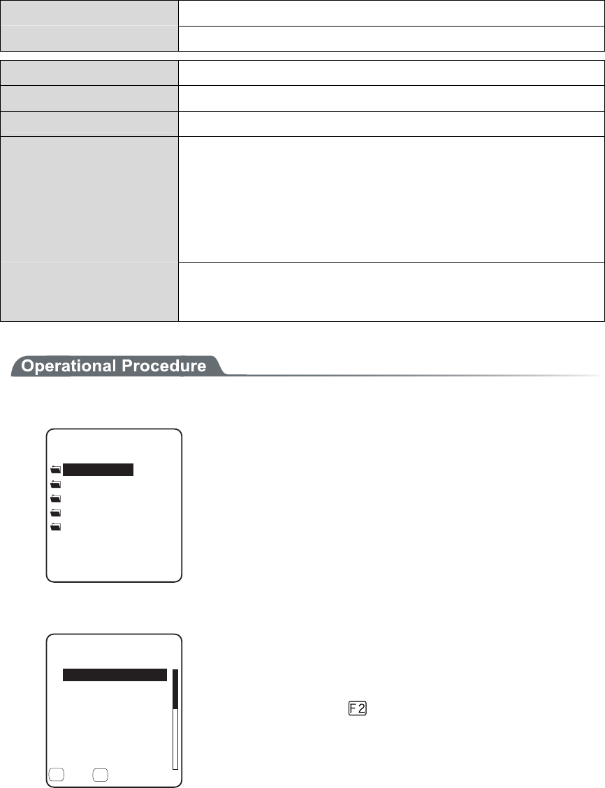
Chapter 3 System menu
3-50
Bit rate 32/40/48/56/64/80/96/112/128/160/192/224/256/320(kbps)
Channels Monaural/Stereo
Extension SFL
Format Audio file list (text style)
MAX items 32
Explanation By using SFL file, many audios and files can be played continuously.
In the file list, the file name is cited by line feeding to the MAX 32 items.
The cited audio file should be stored in the terminal beforehand.
The file names written in the file list are all played only once.
When an Error occurred during playing, the audio file play will stop and
will not play any more.
It is impossible to cite other SFL file inside the SFL file.
Description example ALARM_MELODY.WAV(Changing line)
LOCATION_3F_2.WAV(Changing line)
SHIP_ERROR.WAV
1. From the System menu, select "5:file ".
(KNGV[RG
ǽ#WFKQ
ǽ$KVOCR
ǽ&CVC
ǽ#NNV[RG
ǽ#RRNKECVKQP
Select the kind of the file for Operation. Select "All types ", regard-
less of the kind of the file all files stored in the drives targeted.
2. Selecting a drive.
(KNG(
ǫ%12#0$/2
ǫ*#$#0'41$/2
ǫ%12#0$/2
ǫ-17/'$/2
ǫ-17/'$/2
ǫ/#-'6:6
ǽ/GPWǽ5&TKXG
( (
ǫ:$/2
F Drive becomes the current drive.
When there is no file stored in the F Drive, S Drive will be the cur-
rent drive.
Each time by pressing the key, the current drive changes.
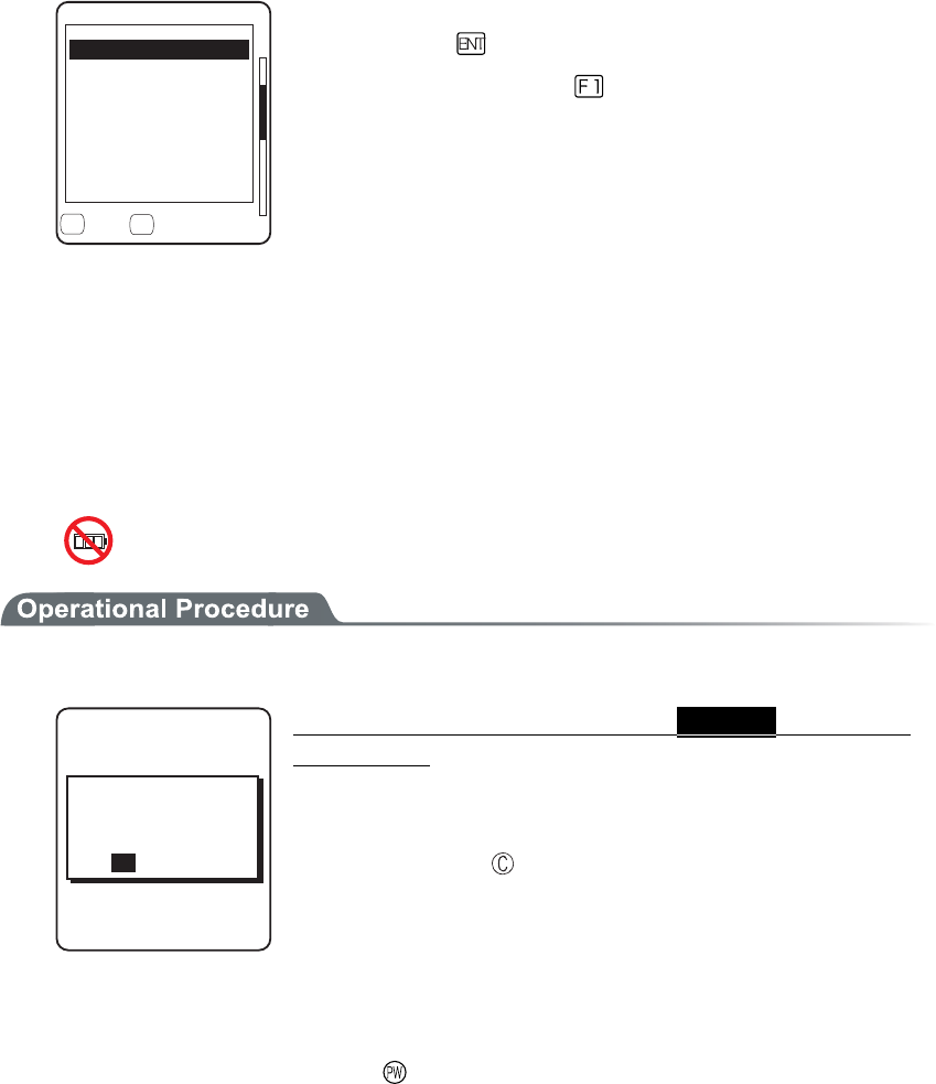
3-12 File Menu
3-51
3. File operation.
(KNG(
ǫ6GU$/2
ǫ%12#0$/2
ǫɮʽʑʍɹʃ*6/
ǫʷʽɺʟɫɮʵʗ
ǫ/#-'6:6
ǽ/GPWǽ5&TKXG
( (
ǫ:$/2
ǫ9):D176
2TQRGTVKGU
7RNQCF
'ZGEWVG
&GNGVG
6GUV
#NNEJGEMUCRRNKGF
#NNEJGMEUTGOQXGF
File alone check box operation (apply checks /remove checks) is
performed by the key.
For other operation, press the key, From the Sub menu, Select
the Operation.
・ Execute
・ Play
・ Viewer
・ Properties
・ Upload
・ Delete
・Test
・ All checks applied
・ All checks removed
■Execute
1. From the Sub menu, select "Execute".
(KNGGZGEWVG
TGIKUVGTYKVJ
#WVQGZGEWVG!
;'501
9QWNF[QWNKMGVQ
Regardless of check box status, Selected application
is executed.
When an SFL file application to be executed is not registered in the
Automatic Launch, register confirmation dialog is displayed.
In addition, Press the key, and [No] is selected.
After selecting, execute the program. To end the application, perform
the operation specified for each application. After termination,
whether the System menu is displayed again or, the power of the ter-
minal turns off is depends on the application.
When the battery lost its power, the alarm appears and the power of
the terminal turns OFF. If you want to stop the application by force,
press the key continuously for 10 seconds while it is running.
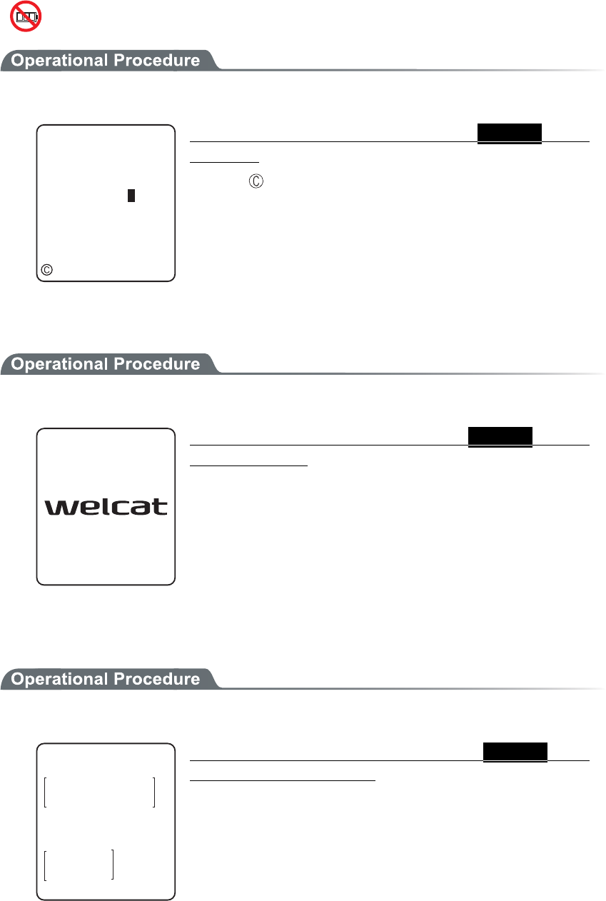
Chapter 3 System menu
3-52
■Play
1. From the sub menu, select "Play".
#WFKQ
2NC[KPI
ǽ5VQR
Regardless of the check box status, Selected audio
file plays.
Press the key to stop and playing.
■Viewer
1. From the Sub menu, select "Viewer".
Regardless of the check box status, Selected bitmap
file is displayed.
Press any key to return to the previous operation.
■Properties
1. From the Sub menu, select "Properties".
(KNGRTQRGTV[
0COG
6[RG=$KVOCR?
5K\G
:$/2
ᵘ?$[VGU
/QFKHKGF
Regardless of the check box status, Selected file's
properties are displayed.
Following properties are displayed.
・ File name
・ File type
・ File size
・ Last modified
・ Library version(application only)
Press any key, to return to the previous operation.
3-12 File Menu
3-53
■Upload
When uploading, please check the following beforehand.
●WLAN
・ The communication setting (IP address, SSID, WEP etc.) between the GTX-100 and the Access
point are correctly set up.
・ The power of the access point and host computer is ON.
・ The access point and host computer is correctly setup or connected.
・ The access point is normally operating.
・ FTP server is running on the host computer.
・ FTP setup (host name, user name etc.) of GTX-100 is correctly setup.
●Bluetooth(Receiving side is the host computer)
・ The power of the host computer is ON.
・ The "BluePorter(WLF-001:optional)" on the host computer is started up.
・ The default device of GTX-100 is setup on the host computer at the receiving side.
●Bluetooth(Receiving side is GTX-100)
・ The default device of GTX-100 is setup on the GTX-100 at the receiving side.
1. From the sub menu, select "Upload".
(KNG(
ǫ6GU$/2
ǫ%12#0$/2
ǫɮʽʑʍɹʃ*6/
ǫʷʽɺʟɫɮʵʗ
ǫ/#-'6:6
ǽ/GPWǽ5&TKXG
( (
ǫ:$/2
ǫ9):D176
2TQRGTVKGU
'ZGEWVG
&GNGVG
6GUV
#NNEJGEMUCRRNKGF
#NNEJGMEUTGOQXGF
7RNQCF
Upload the file with whose check box is checked.
However, when there is no file whose check box is checked, Selected
file is uploaded.
2. Select the device to use.
&GXKEGV[RG
$NWGVQQVJ
9.#0
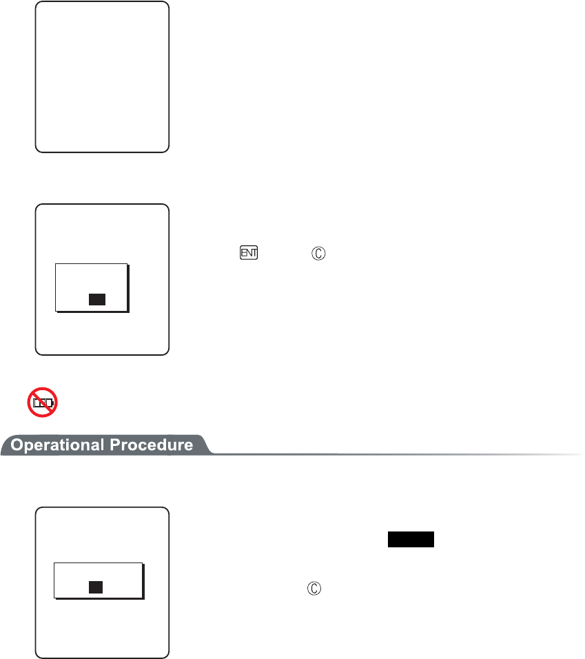
Chapter 3 System menu
3-54
3. Upload start.
7RNQCFKPI
+0&':*6/
Upload status is displayed.
4. Upload is completed.
7RNQCFKPI
+0&':*6/
ᴥᴦ
1-
%QORNGVGF
When many files are checked, (the number of upload success / the
number of checked items)" is displayed in the "Message box".
Press the key, or key.
■Delete
1. From the sub menu, select "Delete".
(KNGFGNGVG
&GNGVGHKNGU!
;'501
Delete the file whose check box is checked.
However, if there is no checked file, Selected file is deleted.
Confirmation dialog is displayed. Select[Yes]or [No].
In addition, Press the key, and [No] is selected.
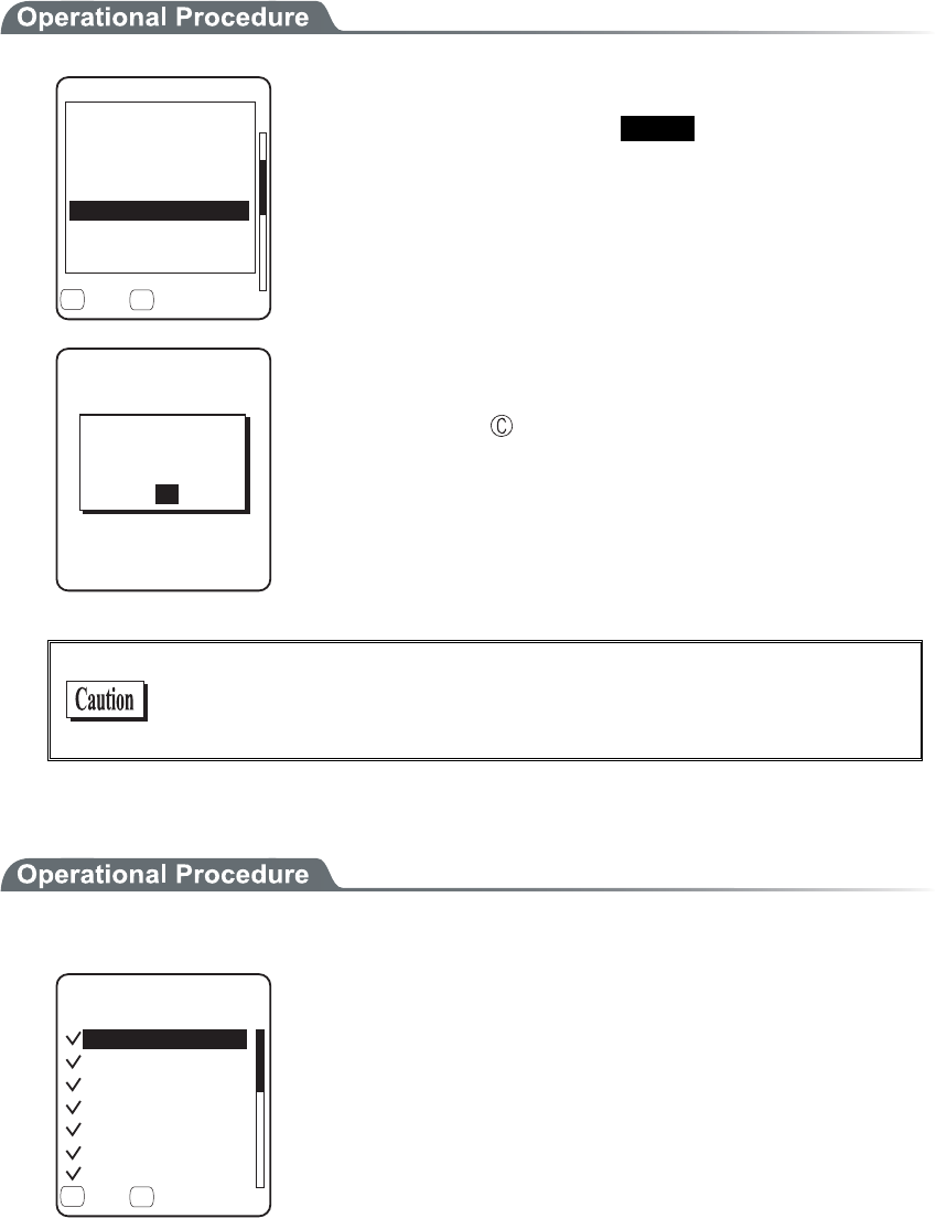
3-12 File Menu
3-55
■Test
(KNG(
ǫ6GU$/2
ǫ%12#0$/2
ǫɮʽʑʍɹʃ*6/
ǫʷʽɺʟɫɮʵʗ
ǫ/#-'6:6
ǽ/GPWǽ5&TKXG
( (
ǫ:$/2
ǫ9):D176
2TQRGTVKGU
7RNQCF
'ZGEWVG
&GNGVG
6GUV
#NNEJGEMUCRRNKGF
#NNEJGMEUTGOQXGF
Test the file whose check box is checked.
However, if there is no checked file, Selected file is tested.
(KNGVGUV
(KNGKUDTQMGP
&GNGVG!
9IZDQWV
;'501
When the tested file is broken, file delete confirmation dialog is dis-
played. Select[Yes][No].
In addition, press the key, and [No] is selected.
When[Yes]is selected, the file is deleted immediately.
When [No] is selected, nothing will be performed.
After the Select, restart the next file testing.
If the broken file is used as it is, an unexpected accident such as the
application's running out of control and so on. It is strongly rec-
ommended to delete the broken file.
■All checks applied
1. From the Sub menu, select "All checks applied".
(KNG(
ǫ%12#0$/2
ǫ*#$#0'41$/2
ǫ%12#0$/2
ǫ-17/'$/2
ǫ-17/'$/2
ǫ/#-'6:6
ǽ/GPWǽ5&TKXG
( (
ǫ:$/2
Check all the check boxes.

Chapter 3 System menu
3-56
■All checks removed
(KNG(
ǫ%12#0$/2
ǫ*#$#0'41$/2
ǫ%12#0$/2
ǫ-17/'$/2
ǫ-17/'$/2
ǫ/#-'6:6
ǽ/GPWǽ5&TKXG
( (
ǫ:$/2
Remove the check from all the check boxes.
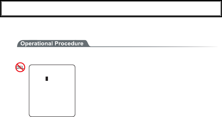
3-13 ID Menu
3-57
3-13 ID Menu
Setup the ID number for identification. Setup the unique number for each terminal. When DHCP function is en-
abled automatic setup is also possible.
1. From the System menu, select "6:ID".
+&
+&ᵘᵚ
Input the terminal ID.
The number of ID allowed to set is from 000 to 999.
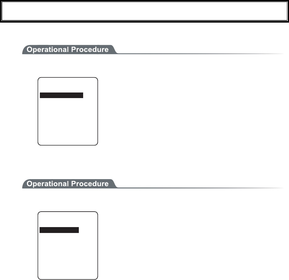
Chapter 3 System menu
3-58
3-14 Device Menu
Setup the hardware device such as Barcode and key. The Device Menu is further classified for each devices.
1. From the System menu, select "7:device".
&GXKEG
$NWGVQQVJ
&KURNC[
-G[
6QPG8KDTCVQT
$CTEQFG
Select the item to setup.
・ Barcode
・ Key
・ Bluetooth
・ Display
・ Tone/Vibrator
3-14-1 Barcode
1. From the Device Menu, select "1:Barcode".
$CTEQFG5ECPPGT
5ECPCPING
&GEQFGNGXGN
4GXGTUG
6TKIIGTOQFG
Select the item to setup.
・ Trigger mode
・ Decode level
・ Scan angle
・ Reverse

3-14 Device Menu
3-59
■Trigger mode
This mode is used to setup the operational condition of the laser scanner on the System menu or the
GTX-100 browser.
This setup is only enabled with the application using "Trigger mode" for barcode scanning.
WebGlider-X browser is one of the applications using trigger mode.
1. Select the item to setup.
6TKIIGTOQFG
2QYGTUCXKPI
ᵘ(WNNᵚ
ᵘ0QTOCNᵚ
+TTCFKCVKQPVKOG
ᵘᵚUGE
6TKIIGTQRGTCVKQP
Select the item to setup.
・ Trigger operation
・ Power saving
・ Irradiation time
●Trigger operation
Setup the operation of the scan key and the irradiation pattern of the laser. A barcode can be scanned
when the irradiation of the laser is turned ON
1. From the sub menu, select the item.
6TKIIGTOQFG
2QYGTUCXKPI
ᵘ(WNNᵚ
ᵘ0QTOCNᵚ
+TTCFKCVKQPVKOG
ᵘᵚUGE
6TKIIGTQRGTCVKQP
#WVQ
&QWDNG
4GNGCUG
0QTOCN
・ Normal
Press the scan key, and the laser irradiates.
・ Double
Press the scan key, and the laser blinks. Press again, the laser irra-
diates.
・ Release
Press the scan key, and the laser blinks , release the scan key, the
laser irradiates.
・ Auto
Regardless of scan key operation, the laser irradiates automati-
cally.
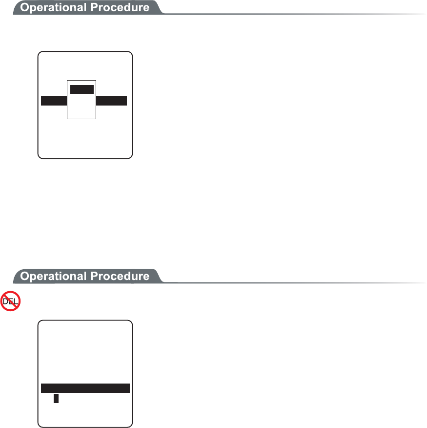
Chapter 3 System menu
3-60
●Power saving
Setup for saving the power consumption when scanning.
1. From the sub menu, select the item.
6TKIIGTOQFG
2QYGTUCXKPI
ᵘ(WNNᵚ
ᵘ0QTOCNᵚ
+TTCFKCVKQPVKOG
ᵘᵚUGE
6TKIIGTQRGTCVKQP
0QPG
(WNN
3WKEM
・ Full
When a Barcode is scanned the laser stops automatically and the
power supply to the scanner part stops as well. The consumed
power gets small, but it takes time to start the next scanning.
・ Quick
When a Barcode is scanned the laser stops automatically but the
power supply to the scanner part continues as well. The consumed
power is large compared to the Full, but it can perform the next
scanning smoothly.
・ None
Power saving mode is not used.
●Irradiation time
Setup the time to turn OFF the laser automatically.
1. Input the time.
6TKIIGTOQFG
2QYGTUCXKPI
ᵘ(WNNᵚ
ᵘ0QTOCNᵚ
+TTCFKCVKQPVKOG
6TKIIGTQRGTCVKQP
ᵘᵚUGE
The time allowed to setup is from 00 to 60 seconds.
In addition, when 00 second is setup, the laser keeps irradiating
without stop.
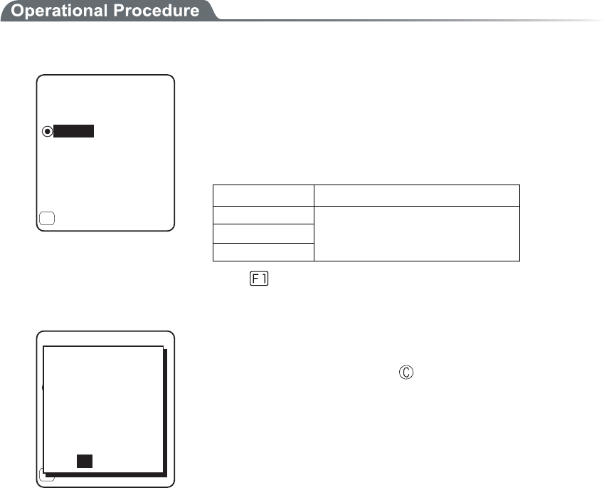
3-14 Device Menu
3-61
■Decode level
Setup the permissible range of the Barcode scanning.
When the Decode level is set to "strict", the barcode label checked strictly.
For this reason the label of poor quality get difficult to scan, but the possibility of miss scanning be-
comes low.
On the other hand, when the Decode level is set to "loose", the barcode label of comparatively poor
quality can be scanned, but the possibility of miss scanning becomes high.
Be sure to check the digit number, data etc in the check digit of the software when the "loose" is set.
1. Decode level Adjustment.
ǽ0QTOCN
&GEQFGNGXGN
Dz.QQUG
)WKFCPEG
Dz5VTKEV
(
The level can be adjusted to 3 stages, "Strict", " Normal", and
“Loose".
The relationship between level value and easiness for scan-
ning is as follows.
The scan level and miss scanning level are proportionate.
Level value Scan (miss scanning) rate
Strict Strict (difficult to miss scan)
Normal ↑↓
Loose Loose (easy to miss scan)
Press the key, and the guidance for setup value is dis-
played.
ǽ0QTOCN
&GEQFGNGXGN
Dz.QQUG
)WKFCPEG
Dz5VTKEV
(
JKIJ
+UKVCNNTKIJV!
OKUTGCFKPIDGEQOGU
;'501
VJGTCVGQH
VJCPVJGUVCPFCTF
5KPEGKVKUNGUU
NGXGNVQTGEQOOGPF
When the level is going to setup to "loose", the guidance for
attention about miss scanning is displayed. Se-
lect[Yes][No].In addition, press the key, to select [No].
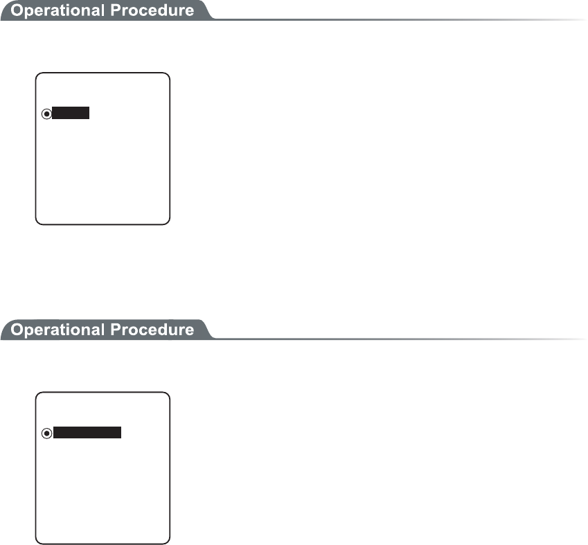
Chapter 3 System menu
3-62
■Scanning angle
Setup the irradiation angle of the laser.
1. Select from either Wide or Narrow.
Dz0CTTQY
5ECPCPING
ǽ9KFG
・ Wide(default)
The irradiation angle of the laser widens.
・ Narrow
The irradiation angle of the laser becomes narrow.
■Reverse
Scan setup of White/ black Reversed Barcode
1. Select from either Prohibition, or, Permission.
Dz2GTOKUUKQP
4GXGTUG
ǽ2TQJKDKVKQP
・ Prohibition (default)
Normally, the barcode with black bar and white space only scanned.
・ Permission
The barcode with reversed white and black of bar and space only
scanned .
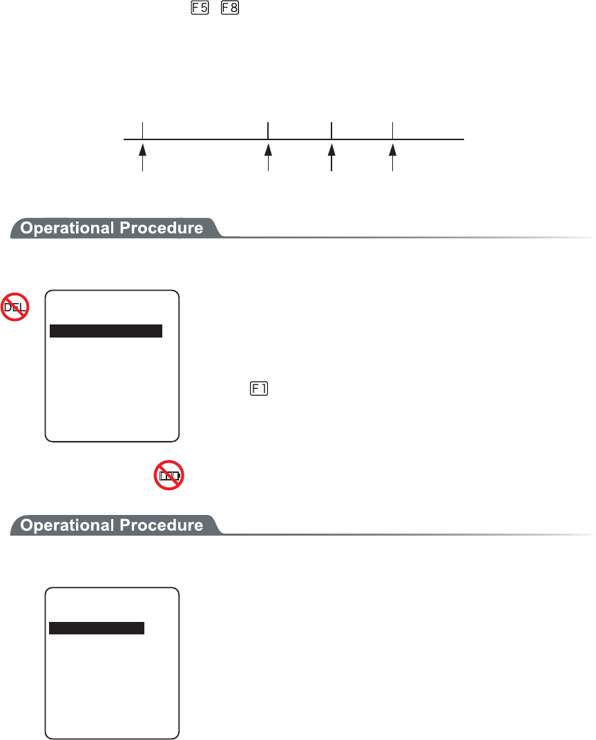
3-14 Device Menu
3-63
3-14-2 Key
Press and hold the direction ( to ) key, the direction key is allowed to enter itself repeatedly.
The time (Key repeat delay): From the time when the press and hold started until it get into the first
repeated entering, and the time (Key repeat rate): until the entering repeated.
(example) repeat delay:1 second, repeat rate:500milli seconds
Ðòåóóáîäèïìä ±óô
òåðåáôåä
²îä
òåðåáôåä
³òä
òåðåáôåä
±óåãïîä ±®µóåãïîä ²óåãïîä
1. From the Device menu, select "2: key".
-G[
-G[TGRGCVTCVG
ᵘᵚOU
ᵘᵚOU
-G[TGRGCVFGNC[
Current setup contents are displayed.
Setup allowed time is from 0100 to 1000milli seconds.
In addition, when 0000milli seconds setup repeated entering is pro-
hibited.
Press the key, and, the guidance is for setup value is displayed.
3-14-3 Bluetooth
1. From the Device menu, select "3:Bluetooth".
$NWGVQQVJ
4GOQVGFGXKEG
.QECNFGXKEG
Select the item to setup.
・ Local device
・ Remote device
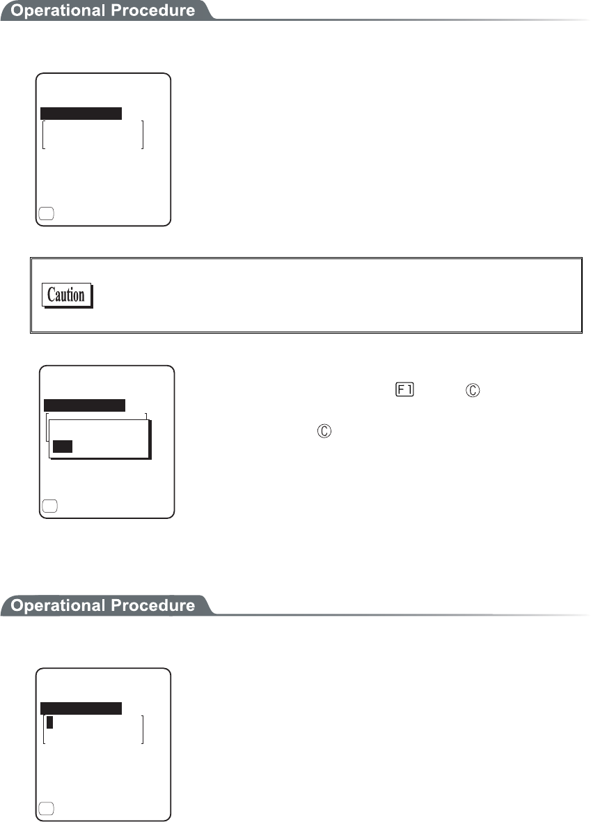
Chapter 3 System menu
3-64
■Local device
Local device setup.
1. Select the item to setup.
)6:
2TQRGTV[
$&#FFTGUU
ᵘ#$##$ᵚ
5GEWTKV[
8GTUKQP
ǽ5CXG
&GXKEGPCOG
(
・ Device name
・ Security
・ Version
As "BD Address" is fixed, setup contents cannot be changed.
Only during the local device setting, the search from the Remote
device is search is accepted. In other case, the search is not ac-
cepted.
)6:
2TQRGTV[
$&#FFTGUU
ᵘ#$##$ᵚ
5GEWTKV[
8GTUKQP
ǽ5CXG
&GXKEGPCOG
(
5CXGUGVVKPIU!
;'501
The setup contents in each item are not saves as it is. In order to
save the setup contents, press the
key or key, and select
[Yes] in the Save confirmation dialog.
In addition, Press the key, and [No] is selected.
●Device name
1. Input the name of the Bluetooth device.
2TQRGTV[
$&#FFTGUU
)6:
ᵘ#$##$ᵚ
5GEWTKV[
8GTUKQP
ǽ5CXG
&GXKEGPCOG
(
For device name, the alphanumeric characters MAX 30 characters,
and the Upper-case character/Lower-case character is distinguished.
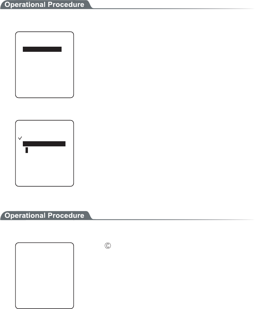
3-14 Device Menu
3-65
●Security
Perform the authentication related setup when connecting.
1. Operate the check box to enable the authentication.
ᵘᵚ
5GEWTKV[
2+0EQFG
ǫ2CKTKPI'PCDNG
When a check box is checked, the authentication is performed in case
the local device received connect request from a Remote device.
Only the Remote device with enabled authentication will be permit-
ted to connect.
2. PIN code setup
ᵘᵚ
ǫ2CKTKPI'PCDNG
5GEWTKV[
2+0EQFG
PIN (Personal Identification Number) code is a password used for
authentication. For this code, characters (A to Z, a to z, 0 to 9, Sym-
bols) and MAX 16 digits can be entered.
As a security measure, entered PIN code is displayed being converted
into a hidden character (*).
●Version
1. Check the firmware version of the built in Bluetooth device.
8GTUKQP
NOR
OCPEUT
JTZ
NUZ
JEK
Press the key, to return to the previous operation.

Chapter 3 System menu
3-66
■Remote device
Remote device setup.
1. Select the item to setup.
4GOQVGFGXKEG
5GCTEJQRVKQPU
5GCTEJHQTFGXKEGU
&GXKEGNKUV
・ Device list
・ Search for devices
・ Serch options
●Device list
Remote device properties to connect can be registered MAX 7 items. Once registered beforehand, you
don't have to set the device properties for each connection.
1. Select the item number to register
&GXKEGNKUV
ǽ
ǽ
ǽ
ǽ
ǽ
ǽ
ǽ/GPW
ǽ
(
ᴥ0Q&GXKEGᴦ
ᴥ0Q&GXKEGᴦ
ᴥ0Q&GXKEGᴦ
ᴥ0Q&GXKEGᴦ
ᴥ0Q&GXKEGᴦ
ᴥ0Q&GXKEGᴦ
ᴥ0Q&GXKEGᴦ
Select the item number, setup the device properties in order.
When device properties have already registered, the device name is
displayed to the right of the item number. When the device is not
registered, [(No Device)] is displayed to the right of the item number.
(Recognized as registered when the device name is of 1 character
more, and the BD address is other than "00:00:00:00:00:00").
The device whose item number is displayed with to its left is a
default device. In the System menu when connecting via Bluetooth,
default device is connected to.
&GXKEGNKUV
ǽ
ǽ
ǽ
ǽ
ǽ
ǽ
ǽ/GPW
ǽ
(
ᴥ0Q&GXKEGᴦ
ᴥ0Q&GXKEGᴦ
ᴥ0Q&GXKEGᴦ
ᴥ0Q&GXKEGᴦ
ᴥ0Q&GXKEGᴦ
ᴥ0Q&GXKEGᴦ
ᴥ0Q&GXKEGᴦ
'TCUG
&GHCWNV
Press the key, and sub menu is displayed.
・ "Default"
Selected device to register is setup as a default device.
・ "Erase"
Erase the registered device properties.
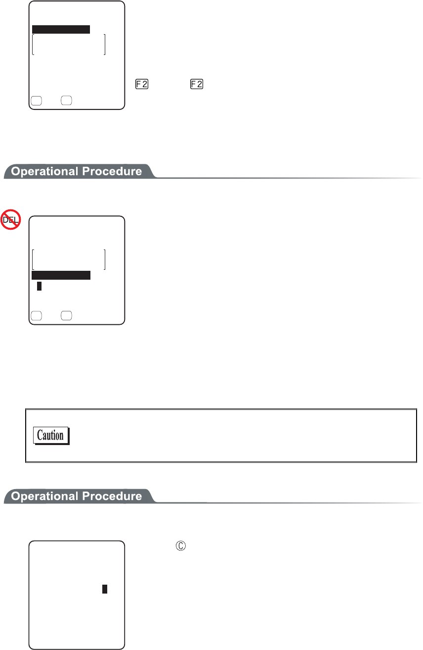
3-14 Device Menu
3-67
2. Select the item to setup.
2TQRGTV[
$&#FFTGUU
ᵘ#$##$ᵚ
5GEWTKV[
ǽ5CXGǽ5GCTEJ
&GXKEGPCOG
( (
・ Device name
・ BD Address
・ Security
The operation procedure of device name for security is same as that
of the local device.
Press the key to search the Remote device. To setup the de-
tected Remote devices the registered device is also possible.
●BD Address
1. Input the BD Address.
&GXKEGPCOG
2TQRGTV[
$&#FFTGUU
ᵘ#$##$ᵚ
5GEWTKV[
ǽ5CXGǽ5GCTEJ
( (
BD address is a device unique hardware address.
It is the fixed length of 16 digit character (0 to 9, A to F) 12 dig-
its.
●Device search
Searches the Remote device. To setup the detected Remote device as the registered device is also pos-
sible.
When you want to include the other GTX-100 as the target of device
search, it is necessary to set the targeted terminal to "Local Device
Setup".
1. Search start.
5GCTEJHQTFGXKEGU
5GCTEJKPI
Press the key, and search to stop.
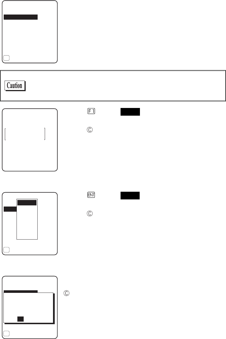
Chapter 3 System menu
3-68
2. The search result list is displayed.
75$#FCRVQT
5GCTEJTGUWNVU
.CDGN2TKPVGT
ǽ2TQRGTV[
(
The device name list of the detected remote device is displayed.
The device name that can be detected is limited to alphanumeric
characters. Be sure not to use the Kana-Kanji as the device name of
the host computer.
2TQRGTV[
75$#FCRVQT
$&CFFTGUU
ᵘ%&&$'ᵚ
&GXKEGPCOG
Press the
key, and Selected Remote device's device name and
BD address are displayed.
Press the key, to return to the previous operation.
3. Select detected remote device.
75$#FCRVQT
5GTCTEJTGUWNVU
.CDGN2TKPVGT
ǽ2TQRGTV[
(
4GOQVG
4GOQVG
4GOQVG
4GOQVG
4GOQVG
4GOQVG
4GOQVG
Press the key, and Selected Remote device's device name, BD
address are displayed.
Press the key to return to the previous operation.
4. Select the registered number of the registered device.
75$#FCRVQT
5GCTEJTGUWNVU
.CDGN2TKPVGT
ǽ2TQRGTV[
(
9QWNF[QWNKMGVQ
QXGTYTKVGKV!
TGCF[TGIKUVGTGF
;'50Q
6JGTGOQVGJCUCN
When the already registered number is selected, overwriting confir-
mation dialog is displayed. Select [Yes][No]. In addition, press the
key, and [No] is selected.

3-14 Device Menu
3-69
●Search option
Set the upper limit of the number of Remote devices detected by device search.
1. Input the number of devices for search.
5GCTEJQRVKQP
5GCTEJ/#:ᵘᵚ
The number of devices allowed to setup is from 1 to 9.
The more the number of devices for search is the longer the search
time becomes.
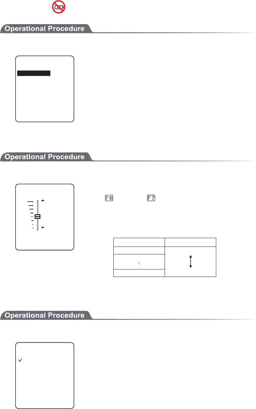
Chapter 3 System menu
3-70
3-14-4 Display
1. From the Device, select "4:Display".
&KURNC[
.WOKPQUKV[
%QPVTCUV
Select the item to setup.
・ Contrast
・ Luminosity
■Contrast
1. Display Contrast Adjustment.
(*KIJ
FKURNC[EQPVTCUV
.GXGNᴷ
(.QY
The contrast of the display can be adjusted from 1 to 8.
Press the key for Up, key for Down, then the slider moves.
The contrast changes in real time in line with the slider's upward and
downward movement, the status of the contrast level can be checked
immediately. The relationship between level value and contrast is as
follows.
Level value Contrast
8 High (thick)
1 Low (thin)
■Backlight luminosity
1. Operate the check box to set high luminosity.
.WOKPQUKV[
ǫ*KIJ.WOKPQUKV[
When check is applied the luminosity when the backlight ON becomes
high luminosity.
However, in that case check the consumed power becomes large com-
pared to the status when the check is removed (standard luminosity).
When starts the setup the backlight turns ON automatically, the lu-
minosity changes in real time according to the status of the check.
However, when the battery level is less than the regulated value, the
backlight will not turn ON.
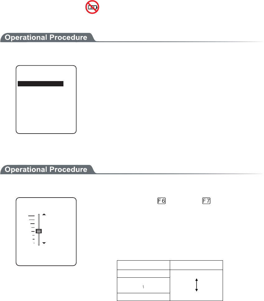
3-14 Device Menu
3-71
3-14-5 Tone/Vibrator
Setup the device such as Sound, LED and Vibrator to alert the worker's attention.
1. From the Device, select "5:Tone/Vibrator".
6QPG8KDTCVQT
%NKEM5QWPF
+PFKECVQTHWPE
8QNWOG
Select the item to setup.
・ Volume
・ Indicator func
・ Click sound
■Volume
1. Adjust Speaker volume.
(/CZ
8QNWOG
.GXGNᴷ
(/KP
It is adjustable from 1 to 8. key for Up, key for Down to
move the slider.
As the sound volume changes in real time in line with the Up and
Down movement of the slider, the status of the level value can be
checked immediately.
The relationship between the level value and sound volume is as fol-
lows.
Level value Sound volume
8 Max
1 Min
Set to 1, if no sound is desired.
■Indicator function
Indicator means the combination of four devices (buzzer/audio /vibrator/LED) that is used to alert the worker's
attention.
By using this indicator allows the worker to know the current status more intuitively. What indicator is used in
what situation is set up by the application. In addition, in the System menu, the "pattern 3" indicator for each
case will be applied.
For example,
・ When confirmed, one high tone sounds somewhat short and the LED green turns ON.
・ When an error occurred, vibrating the Vibrator, beep a low-pitch sound three times and turn ON the
green LED.
Chapter 3 System menu
3-72
And so on, the terminal allows the user varieties of setting according to the user's working environment.
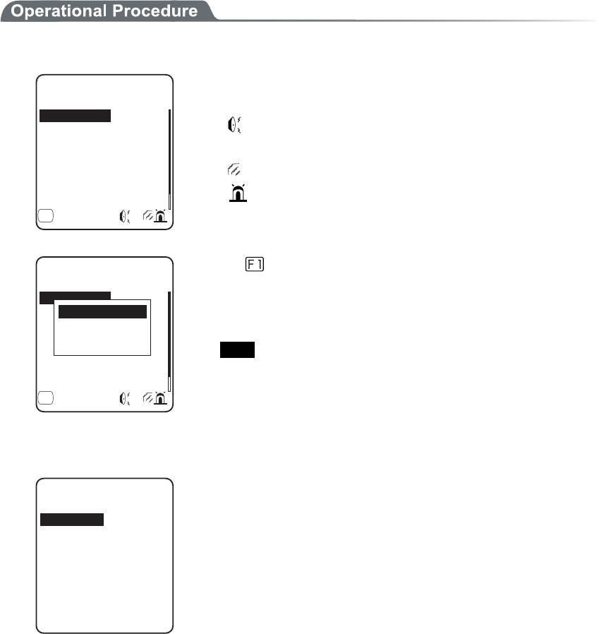
3-14 Device Menu
3-73
There are 5 scenes that represent working such as pressing the key (click) and confirming etc. And one user's
scene, these 6scenes are provided with three patterns respectively.
1. Select the indicator to set.
+PFKECVQTHWPE
%CPEGN
'PVGT
%CPEGN
'PVGT
'PVGT
%NKEM
ǽ/GPWǺ
%CPEGN
(
The icon to show the setup status of the indicator is displayed in right
of the lower part on the display.
:Buzzer is setup.
♪:Audio is setup.
:Vibrator is setup.
:LED is setup.
+PFKECVQTHWPE
%CPEGN
'PVGT
%CPEGN
'PVGT
'PVGT
%NKEM
ǽ/GPWǺ
%CPEGN
(
+PKVKCNK\G
+PKVKCNK\GCNN
2TGXKGY
Press the
key, and sub menu is displayed.
・"Preview"
Current indicator can be experienced.
・"Initialize"
Select pattern setup contents are discarded to return to the ini-
tial value.
・"Initialize all "
Discarding all setup patterns of all scenes and return to the ini-
tial value.
2. Select the device to setup.
&GXKEG
8KDTCVQT
.'&
#WFKQ
$W\\GT
After selecting device, setup the operational condition of the device
in order.
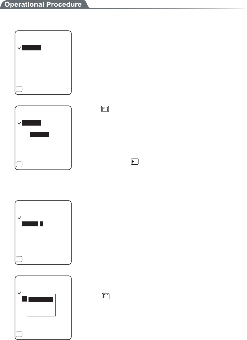
Chapter 3 System menu
3-74
●Operational condition of a device
In the operation condition, there are two kinds, one is common to all devices and the other is unique to
the device.
1. Enable check box operation (common to all devices).
ǫ'PCDNGF
$W\\GT
10OU
(TGS*\
4GRGCV
ǽ/GPW
(
ᵘᵚ
ᵘᵚ
1((OU
ᵘᵚ
ᵘᵚ
The switch to turn ON/OFF the operation of the device.
When checked, the device operates, and when the check is removed
the device does not operate unconditional to other setups.
This setup is displayed as an icon.
ǫ'PCDNGF
$W\\GT
ǽ10OU
ǽ(TGS*\
ǽ4GRGCV
ǽ/GPW
(
ᵘᵚ
ᵘᵚ
ǽ1((OU
ᵘᵚ
ᵘᵚ
+PKVKCNK\G
2TGXKGY
Press the key, and sub menu is displayed.
・"Preview"
Current indicator can be experienced
・"Initialize all "
Discarding setup contents of the pattern and return to the initial
value.
In addition, when the
Menu is displayed in the left of the lower
part of the display, the operation procedure is common to all the op-
erational condition of devices.
2. Input the frequency (buzzer only)
ǫ'PCDNGF
$W\\GT
ǽ10OU
ǽ(TGS*\
ǽ4GRGCV
ǽ5CORNG
(
ᵘᵚ
ᵘᵚ
ǽ1((OU
ᵘᵚ
ᵘᵚ
Setting range is from 0000 to 9999Hz.
ǫ'PCDNGF
$W\\GT
ǽ10OU
ǽ(TGS*\
ǽ4GRGCV
ǽ5CORNG
(
ᵘᵚ
ᵘᵚ
ǽ1((OU
ᵘᵚ
ᵘᵚ
.QYVQPG
/GFKCPV
*KIJVQPG
The contents of the function key guidance displayed in the left of the
lower part of the display changes during the frequency is entered.
Press the
key, and sub menu of the frequency samples are dis-
played.
Fine-tuning the value based on the samples facilitates the setup.
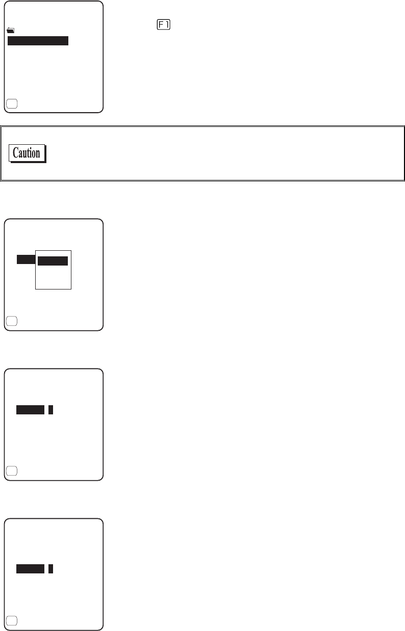
3-14 Device Menu
3-75
3. Selecting a file name (audio only).
4GHGTGPEGVQHKNG
'4414A/5)/2
'06'49#8
ǽ2TQRGTV[
(
.+565(.
%.+%-9#8
ǽ2TGKPUVCNN
Select the audio file from the file list.
Press the key, and properties related to the selected file is dis-
played.
Select the "built in audio ". The audio file list that is stored before-
hand in the system area of the terminal is displayed.
When an extension specifies the MP3 or SFL file on the indicator,
will not be played by the application unless the Library linked on the
application is Ver.1.10 or later.
4. Color Select (LED only).
ᵘ4GFᵚ
ǫ'PCDNGF
.'&
ǽ10OU
ǽ%QNQT
ǽ4GRGCV
ǽ/GPW
(
ᵘᵚ
ǽ1((OU
ᵘᵚ
ᵘᵚ
4GF
)TGGP
1TCPIG
From sub menu, select the item.
5. Input the ON time (buzzer/Vibrator/LED).
ǫ'PCDNGF
8KDTCVQT
4GRGCV
ǽ/GPW
(
1((OU
ᵘᵚ
ᵘᵚ
ᵘᵚ
10OU
Operation time of the device for one performance.
Setting range I from 00000 to 99999milli seconds.
If 00000milli second is setup the device keeps operating.
6. Input the OFF time (buzzer/Vibrator/LED).
ᵘᵚ
10OU
ǫ'PCDNGF
8KDTCVQT
4GRGCV
ǽ/GPW
(
ᵘᵚ
ᵘᵚ
1((OU
OFF time of the device for one performance.
The setup range is from00000 to 99999milli seconds.
If 00000milli second is setup the operation stops after the period
specified by ON time (milli seconds).
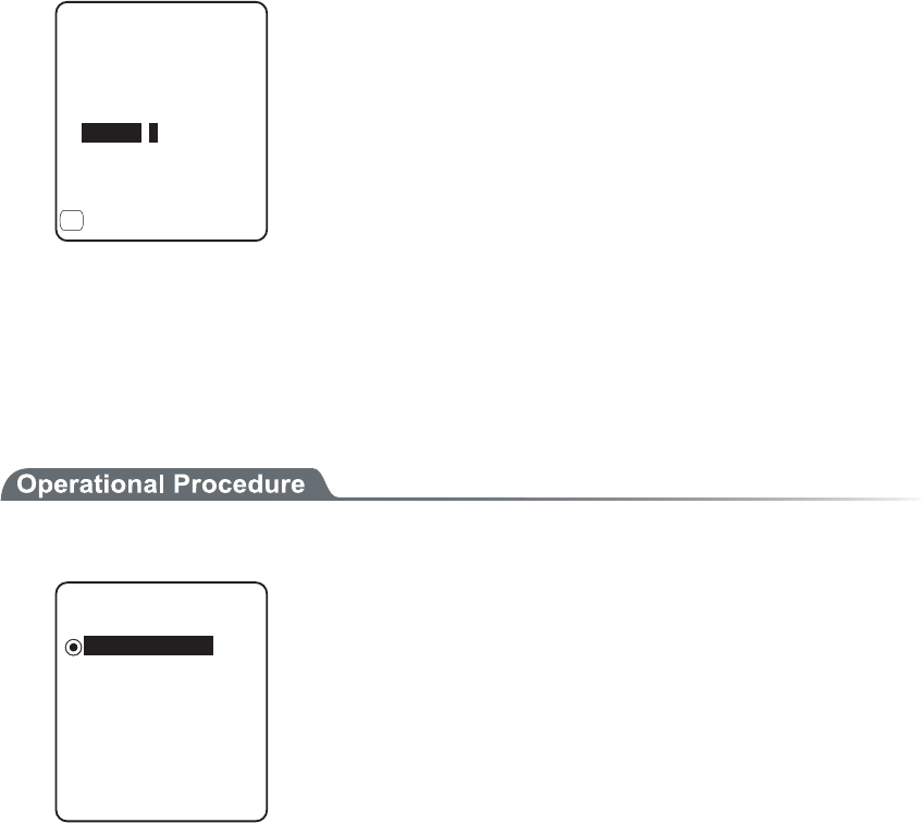
Chapter 3 System menu
3-76
7. Input the number of times to repeat (Common to all devices).
ᵘᵚ
ᵘᵚ
1((OU
ᵘᵚ
10OU
ǫ'PCDNGF
8KDTCVQT
4GRGCV
ǽ/GPW
(
The number of times to repeat the operation on and off.
The setup range is from 00 to 99.
If 00 is set, it repeats until the device is operated.
■Click Sound
Setup whether to play the sound or not when the key at the terminal is pressed. The sound can be se-
lected from "Single Beep sound" and "Numeric read out audio ". Click sound is played immediately
when the key is pressed. When a sound played by application or indicator, the latter sound interrupt
the previous sound. According to the timing, the interruption makes the sound somewhat mixed.
1. Select the sound pattern played when the key is pressed.
Dz$GGR
%NKEM5QWPF
Dz$GGR#WFKQ
Dz#WFKQ
ǽ0QPG
・ None (default)
Key Click sound is not played.
・ Beep
For all keys the beep sound is played when any key is
pressed.
・ Beep + Audio
When numeric keys are pressed the numeric is called out
in audio (in Japanese). When other key is pressed Beep
sound is played.
・ Audio
Only when the numeric keys are pressed numeric is
called out in audio. When other keys are pressed, no sound
is played.
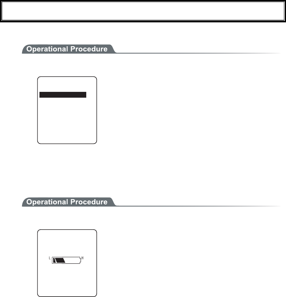
3-15 Manage Menu
3-77
3-15 Manage Menu
Checking the standard properties of GTX-100 and improvement and maintenance of the performance.
1. Select the item to setup.
/CPCIGOGPV
+PKVKCNK\G
%NQPG
5[UVGOXGTUKQPU
&TKXG
/QVJDCNN
9K\CTF
$CVVGT[NGXGN
Select the item to setup.
・ Battery level
・ System versions
・ Initialize
・ Clone
・ Drive
・ Mothball
・ Wizard
3-15-1 Battery level
Check the Battery level of the battery pack. Just look at the Battery level as a reminder.
1. From the Management select "1:Battery level".
$CVVGT[NGXGN
Battery level is displayed in 6 stages.
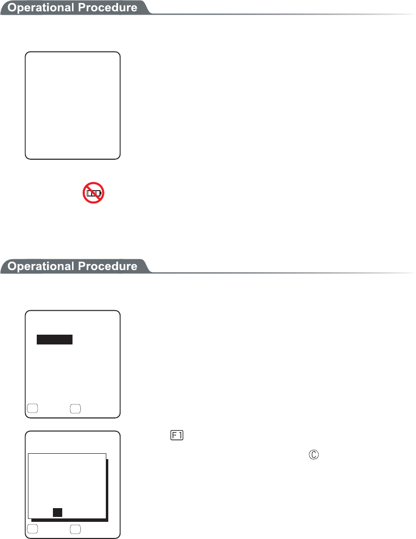
Chapter 3 System menu
3-78
3-15-2 System versions
The handy terminal system program (OS) version is displayed.
1. From the Management, select "2:System versions".
5[UVGOXGTUKQPU
ǽǽǽǽǽǽǽǽǽǽ
15
OS version is displayed.
3-15-3 Initialize
Initializing the Registry and the drive.
When the initialization is performed, the setup contents will return to the Factory setup and all files will be de-
leted. When you perform the initialization take deepest cares with this understanding.
1. From the Management, select "3:initialize".
+PKVKCNK\G
ǫ5&TKXG
ǫ(&TKXG
ǽ'ZGEWVGǽ/GPW
( (
ǫ4GIKUVT[
Check the item that you want to initialize.
If no item is checked, initialization cannot be executed.
+PKVKCNK\G
ǫ5&TKXG
ǫ(&TKXG
ǽ'ZGEWVGǽ/GPW
( (
ǫ4GIKUVT[
'ZGEWVG!
;'501
+HKPKVKCNK\G
UGVVQCFGHCWNV
QTCNNHKNGUCTG
FGNGVGF
Press the key, and execute confirmation dialog is displayed.
Select [Yes] or [No]. In addition, press the key, and [No] is se-
lected.

3-15 Manage Menu
3-79
+PKVKCNK\G
ǫ5&TKXG
ǫ(&TKXG
ǽ'ZGEWVGǽ/GPW
( (
ǫ4GIKUVT[
#NNEJGEMUTGOQXGF
#NNEJGEMUCRRNKGF
Press the key, and sub menu is displayed.
・"All checks applied"
Apply checks to all check boxes.
・"All checks removed "
Remove all checks from the check boxes.
2. Initialization start.
ǫ4GIKUVT[
+PKVKCNK\G
ǫ(&TKXG
+PVKCNK\GKPI
The checked items are initialized in order.
3. Initialization is completed.
ǫ4GIKUVT[
+PKVKCNK\G
ǫ(&TKXG
%QORNGVGF
5JWVFQYP
1-
Press the key, or key.
When the Registry is initialized, turn off the power.
When initializing the Registry, if there is no file in the F drive, the F
drive will be initialized automatically with or without check.
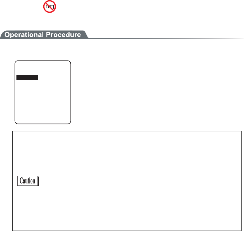
Chapter 3 System menu
3-80
3-15-4 Clone
Copying the contents on the Registry and F drive of the other GTX-100, duplication is created.
1. From the Management, select "4:Clone".
%NQPG
%QR[
/CUVGT
In the case of to copy GTX-100, select "1:Master ".
In the case of to be duplicated on GTX-100, select "2:Copy".
・ Master
・ Copy
When you perform the cloning take deepest care with under-
standing the following items.
・ Copy terminal performs initialization inside the Copy terminal
before Receiving the data from the Master terminal. For this
reason when Clone is failed, the setup value will return to the
Factory setup or all files will be deleted.
・ As the Copy terminal performs initialization at first, and it may
take time to get into the state that the clone can be performed.
・ When transferring registry and file from the Master terminal,
perform cloning after confirming that the Copy terminal is in the
condition to be able to perform the "Clone"
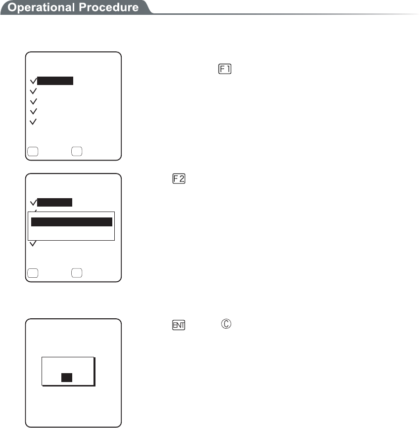
3-15 Manage Menu
3-81
■Master
Setup the "Copy GTX-100" on the default device of the Master beforehand
1. Select the item to clone.
%NQPGOCUVGT
ǫ7UGT
ǫ7PKSWG
ǫ5GEWTKV[
ǫ(&TKXG
ǽ'ZGEWVGǽ/GPW
( (
ǫ5[UVGO
After confirming that the Copy terminal is in the condition to be able
to "Clone", press the key to start Clone.
%NQPGOCUVGT
ǫ7UGT
ǫ7PKSWG
ǫ5GEWTKV[
ǫ(&TKXG
ǽ'ZGEWVGǽ/GPW
( (
ǫ5[UVGO
#NNEJGEMUCRRNKGF
#NNEJGEMUTGOQXGF
Press the key, and sub menu is displayed.
・"All checks applied."
Apply checks to all check boxes.
・"All checks removed "
Remove all checks from check boxes.
2. Clone is completed.
%NQPGOCUVGT
%QORNGVGF
1-
Press the
key or key.
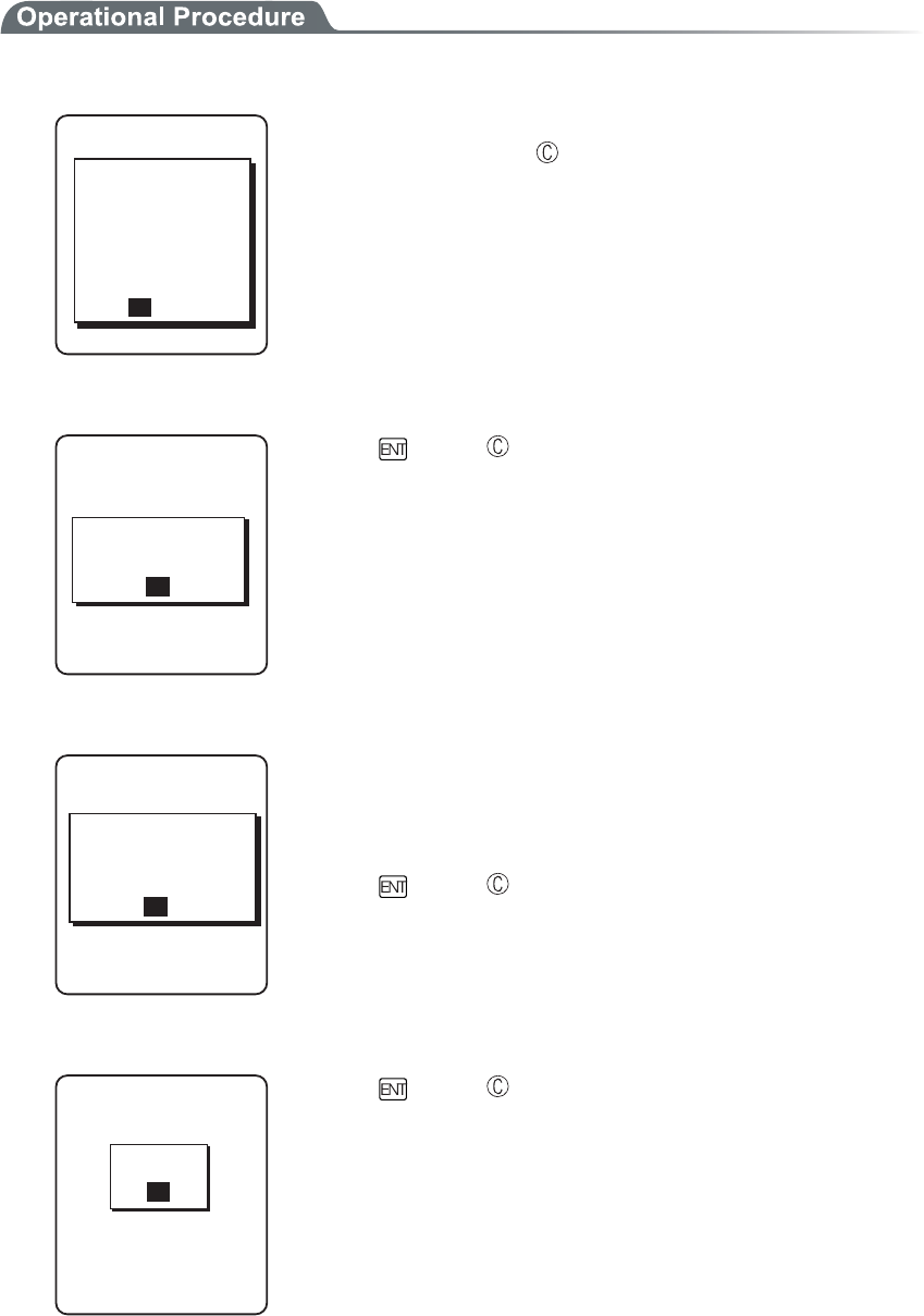
Chapter 3 System menu
3-82
■Copy
1. Initializing itself.
%NQPGEQR[
ǽǽǽǽǽǽǽǽǽǽ
ǽ
ENQPGUGVVQC
FGHCWNVQTCNN
+HKVGZGEWVG
FGNGVGF
;'501
HKNGUCTG
'ZGEWVG!
Execute confirmation dialog is displayed. Select from either [Yes] or
[No]. In addition, press the key, and [No] is selected.
2. It is in the state the Clone is enabled.
%NQPGEQR[
ǽǽǽǽǽǽǽǽǽǽ
ǽ
TGCF[VQGZGEWVG
6JG%NQPGKU
1-
Press the key or key to start Clone.
3. Confirm master display.
%NQPGEQR[
ǽǽǽǽǽǽǽǽǽǽ
ǽ
VJCOCUVGTKU
2NGCUGEJGEMVJCV
1-
EQORNGVGF
At the Copy terminal side, it cannot confirm that the Clone has com-
pleted, be sure to confirm that the transfer has completed on the dis-
play at the Master file. If the transfer from the Master file has not
completes, execute the Clone again.
Press the key or key.
4. Turn OFF the power.
%NQPGEQR[
ǽǽǽǽǽǽǽǽǽǽ
ǽ
5JWVFQYP
1-
Press the key or key.
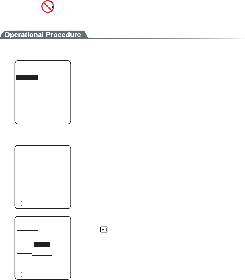
3-15 Manage Menu
3-83
3-15-5 Drive
Confirmation of various properties and maintenance for the drive is performed.
1. From the Management, select "5:Drive".
&TKXGUGNGEVKQP
5&TKXG
(&TKXG
Selecting a drive.
2. The properties of the drive are displayed.
ᵘ?$[VGU
(&TKXGRTQRGTV[
%CRCEKV[
ᵘ?$[VGU
(TGGURCEG
7UGFURCEG
ᵘ?$[VGU
(KNGU
ᵘᵚ
ǽ&GHTCI
(
Following properties is displayed.
・Capacity
・Used space
・Free space
・Files(Used number/Max number)
ᵘ?$[VGU
(&TKXGRTQRGTV[
%CRCEKV[
ᵘ?$[VGU
(TGGURCEG
7UGFURCEG
ᵘ?$[VGU
(KNGU
ᵘᵚ
ǽ&GHTCI
(
0QTOCN
&GGR
F drive can be optimized by performing defrag.
Press the key, and a dialog is displayed.
・"Normal"
The unnecessary area generated in the process of writing
and/or deleting files is physically deleted.
・"Deep"
In addition to normal execute, rearranging the acquired free
area to a continuous area.
It takes some seconds to some 10 seconds to complete Deep
Execute depending on the status of the drive. Usually, Normal
Execute is recommended.
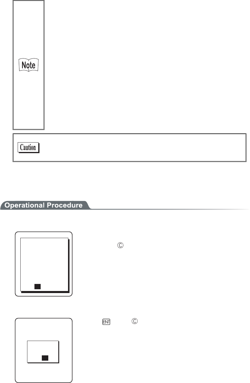
Chapter 3 System menu
3-84
Writing or deleting files repeatedly in the F drive may cause the free
space to be fragmented over time, ultimately making it impossible to
store a large program file. Defragmentation is a process that reduces
the amount of fragmentation and reclaims fragmented space into a
continuous space.
Defragmentation is usually not required because the system pro-
gram maintains the F drive in a clean state by performing defrag-
mentation automatically at each file update. However, if you tend to
update files or perform other affecting actions frequently, frag-
mentation may progress rapidly, soon making the free space in-
adequate. If the F drive information indicates that the free space is
very small relative to the total capacity and the space in use, we
recommend that you perform “deep”defragmentation to create
sufficient free space.
While the system program is performing defragmentation auto-
matically, it may require a longer time for file update or other ac-
tions, this is not an abnormal condition.
When the battery pack is removed in the course of defrag, a file or
the System program may be corrupted. Never remove the battery
pack during defrag.
3-15-6 Mothball
Setup to suppress the consumption of the battery when the GTX-100 is not used for a long period.
1. From the Management, select "6:Mothball".
/QVJDCNN
UWRRTGUUKPI
;'501
TGUWOGCPFVJG5
FTKXGCTGFGNGVG
6JGEQPVGPVUQH
FKPUVGCFQH
EQPUWORVKQPQHC
DCEMWRDCVVGT[
Execute confirmation dialog is displayed. Select [Yes] or [No].
Then, press the key, and [No] is selected.
2. Preparation for prolonged storage is complete.
%QORNGVGF
5JWVFQYP
/QVJDCNN
1-
Press the key or key.
Turn OFF the Power.

3-15 Manage Menu
3-85
3-15-7 Wizard
The wizard executed at the initial boot of the terminal can be called back again. In order to perform communica-
tion between the terminal and the server, the minimum necessary setting is enabled.
1. From the Management, select "7:Wizard".
9K\CTF
%QOOWPKECVKQPUGV
VKPIECPDGFQPG
5VCTVYK\CTF!
YKVJIWKFCPEG
;'501
Select [Yes] or [No].
Select [Yes], then perform the setup of WLAN and perform the
TCP/IP setup to execute the wizard. Select [No] to return to the pre-
vious screen.
See"3-6-4 Executing Setup Wizard"(P.3-10), for details.
Chapter 3 System menu
3-86
3-16 Test Menu
Hardware device test.
1. From the System menu, select "9:Test".
6GUV
$CTEQFG
&KURNC[
$NWGVQQVJ
-G[
9.#0
Select the item to setup.
・ WLAN
・ Bluetooth
・ Barcode
・ Display
・ Key
2. Select target device.
3-16-1 WLAN
Test for Wireless Communications and the test for IP Network communication.
1. From the test, select "1:WLAN".
9.#0VGUV
ǽǽǽǽǽǽǽǽǽǽ
#25GCTEJ
9.#0RKPIVGUV
%QPHKIWTCVKQP
3-16 Test Menu
3-87
■Configuration
Setup the execute condition of the ping command. Wireless test is performed by ping.
1. Select "1:Configuration".
ᵘᵚ
%QPHKIWTCVKQP
2CEMGVUK\G
=?$[VGU
6KOGQWVVKOG
=?UGE
6TKCNEQWPV
ᵘᵚ
*QUVCFFTGUU
●Host address
Specifies the IP address of the targeted device to confirm the communication.
● Packet size (default 1472 bytes)
Select the size of the data packet (in bytes) to be transmitted.
permissible value :32, 64, 128, 256, 512, 1024, 1472
●Time out time (default 3 seconds)
Time out time is setup by 1 seconds unit.
permissible value :1 to 255 seconds
●Trial count (default 4 times)
Set the number of attempts that can be made at transmitting the ping.
Setup enabled value :1 to 255 times
When 0 is specified, transmission of the ping command will continue until the key is pressed.
Chapter 3 System menu
3-88
■WLAN/ping test
WLAN test is performed by executing the ping command. The ping packet is continuously transmitted
to the Host IP address setup at "Configuration". Displayed contents are the result of ping command,
the MAC address of the synchronized access point, communication quality (LinkQ), the received ra-
dio signal strength(ASL), applied channels and displayed.
1. Select "2:WLAN/ping test".
RKPI
2KPI6KOGQWV
0Q$[VGU
.PM3ǪǪǪǪǪǪ
%*
#5.ǪǪǪǪǪǪ
#2A/#%=#(#$?
*QUV
<1st line> The title of this test.
<2nd line> Host IP address to be communication tested
<4th line> The result is displayed.
When succeeded
Result time is displayed. (Unit: msec)
Time out
"ping Timeout" is displayed.
When interrupted by the key
"stopped" is displayed.
<5th line > Transmitted packet number(counted up one by one) and
packet size.
<6th line> LinkQ indicator is displayed.
LinkQ (means the communication quality to the access
point) is displayed.
<7th line> Synchronized channel are displayed.
<8th line> ASL indicator
ASL (means the strength of the radio signal received from
the access point) is displayed.
<10th line> MAC address of the access point while wireless commu-
nications is displayed.
To get the stable enough communication performance it is rec-
ommended that the indicator should be LinkQ 4 or more.
In the case of EAP authentication or PSK(TKIP/CCMP), an error
message is displayed when authentication is failed.
The LinkQ in the 6th line and the ASL indicator on the 8th line do
not show the strength of the radio signal correctly, just have this as
a remindar of the communication status.
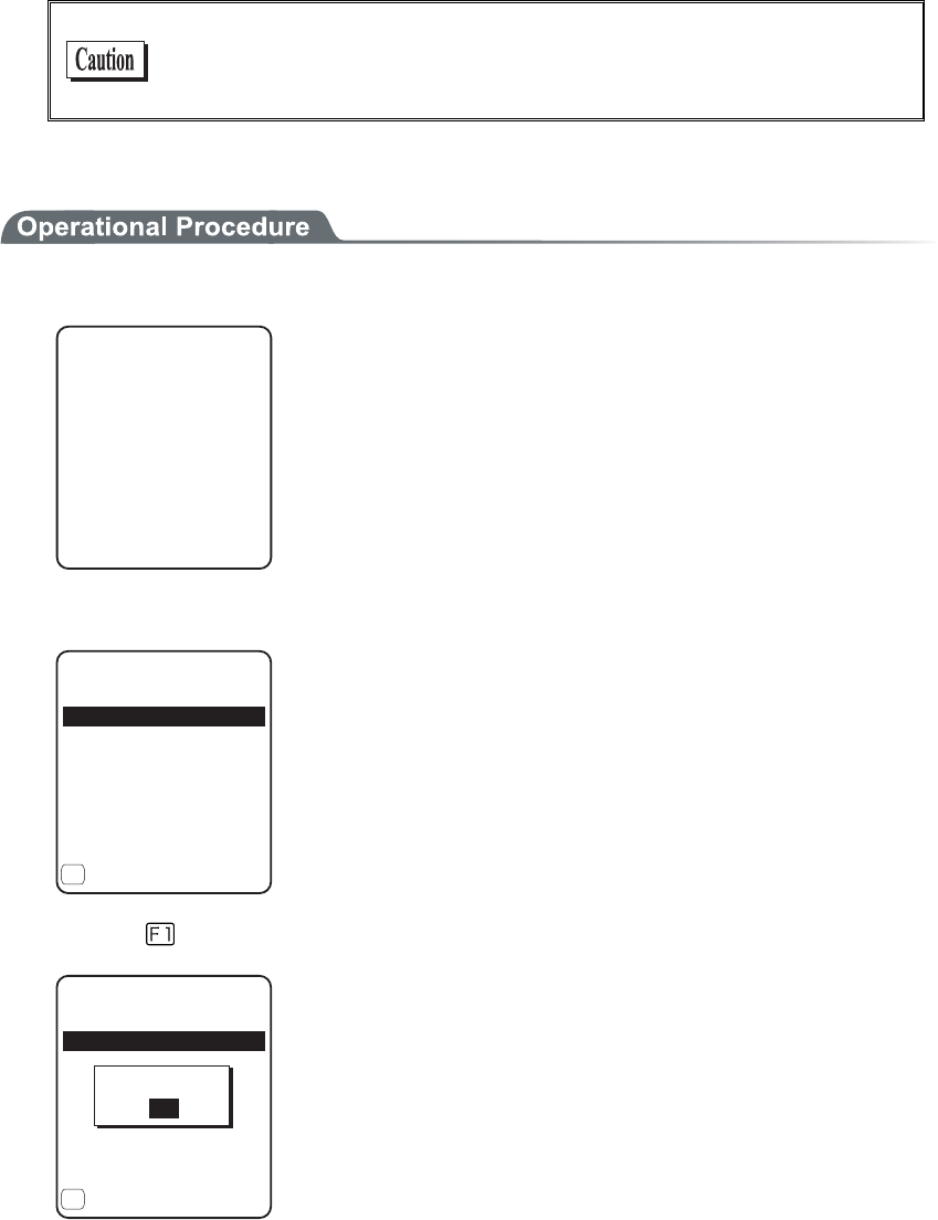
3-16 Test Menu
3-89
■AP Search
To search the access point matches the SSID setup on the terminal.
When the SSID of the terminal is setup to "ANY", it is possible to search all the access points around
there.
This is only performed when the setup at the access point, is set up
as respond to "ANY". From security's point of view, the response to
"ANY" may be disabled.
Displayed contents as a result of searching are MAC address, channel, SSID.
1. Select "3:AP Search".
#2UGCTEJ
5GCTEJKPI
2. The result of searching is displayed after several seconds to some ten seconds.
5GCTEJTGUWNVU
#(&%'
#(&(
#(&&
ǽ2TQRGTV[
(
<1st line> The title of the test result.
<3rd line or after> The MAC address of the detected access point
and the channel number.
<10th line> The key guidance that displays SSID.
3. Press the
key, and the SSID set up at the selected access point is displayed.
5GCTEJTGUWNVU
#(&%'
#(&(
#(&&
ǽ2TQRGTV[
(
55+&)6:
1-
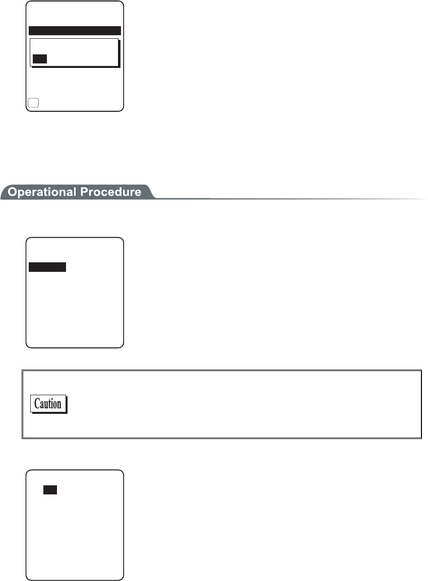
Chapter 3 System menu
3-90
4. Select an access point, the confirmation screen is displayed to set the SSID setup on the access
point to the terminal. Confirmation screen is displayed to allow the SSID setup on the access point
to the terminal.
5GCTEJ4GUWNV
#(&%'
#(&(
#(&&
ǽ2TQRGTV[
(
+U55+&UGVCU)6:
;'50Q
3-16-2 Bluetooth
By using other terminal and Bluetooth, one to one communication is performed.
1. From the Test, select "2:Bluetooth".
4QNG
ǽǽǽǽǽǽǽǽǽǽ
5NCXG
/CUVGT
Select the connecting method with Bluetooth device.
Master has the leadership on connection, and the Slave obey the
Master's direction.
The connection only performed between Master and Slave.
In addition, Master and Slave are only temporary relationship on the
connecting stage.
After the connection the relationship between the Master and Slave
will be dissolved.
Before executing Bluetooth communication, the master device
should be set up as a Default Device on the slave device (or a ter-
minal). With regard to the setting method of the terminal, please
refer to "■Remote device"(P.3-66).
2. Communication test start.
$NWGVQQVJVGUV
Press the key, upload the corresponding key data and display on the
screen (local echo) at the same time.
When the data is received, it appears highlighted on the display.
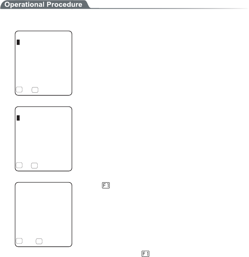
3-16 Test Menu
3-91
3-16-3 Barcode
Barcode scanning test perform.
In addition, this barcode scanning test is not subject to trigger mode.
1. From the test menu, select "3:Barcode".
$CTEQFGVGUV
6[RG,#0
.GPIVJ
ǽ*':1RVKQP
( (
Barcode is scanned in a normal scanning mode.
The scanned Barcode, the kind of Barcode, and the digit number are
displayed.
$CTEQFGVGUV
6[RG,#0
.GPIVJ
5WEEGUU
ǽ*':1RVKQP
( (
Press and hold the scan key for 1 second to get into the continual
scan mode.
While the scan key is pressed, the laser irradiates, and continues
scanning the barcodes. Release the scan key to return to the ordinary
scan mode.
In addition to the scanned Barcode, the kind of Barcode, and the digit
number, scan success rate is also displayed.
$CTEQFGVGUV
ǽ#5%++1RVKQP
( (
Press the key to convert the character code to display.
・"ASCII" (default)
displayed in ASCII Character code.
・"HEX"
displayed in hexadecimal number. For example 16 digit con-
verted from "5"to"35", "m" to "6D", 1 character is displayed as
16 digit positive 2 characters.
Each time by pressing the key, the display switches.

Chapter 3 System menu
3-92
■Barcode Option
%JGEMFKIKV
$CTEQFGQRVKQP
455
,#0'#072%
Press the key to allow setting varieties of barcode options.
In addition, this setup only enabled during the barcode testing.
●Check digit
Setup whether to check the check digit.
・ [Check Enable] is set to OFF (default)
The check of check digit is disabled.
・ [Check Enable] is set to ON
The check of check digit is enabled.
●JAN/EAN/UPC
Setup the scanning condition of add-on code of JAN/EAN/UPC.
・ Ignore Add-on (default)
Add-on code scanning disabled.
・ Read all
Both can be scanned unconditional whether add-on code is added.
・ Read Add-on only
JAN/EAN/UPC with add-on code only can be scanned.
●RSS
Setup the scanning condition of RSS Stacked.
・ Prohibition (default)
RSS stacked scanning is disabled.
・ Permission
Scanning RSS Stacked is enabled.

3-16 Test Menu
3-93
3-16-4 Display
Display test.
1. From the Test, select "4:Display".
YKFGYKFG
3WCF3WCF
6CNN6CNN
JCNHJCNH
FQVHQPV
Test the function of LCD. When test starts the backlight turns ON
automatically. However, when the Battery level is low it does not
turn ON.
Each time by pressing the key except for the key, 4 kinds of dis-
play contents switches like slides.
1. 12 dot font-various double width character
↓
2. 16 dot font-various double width character
↓
3. The display is highlighted from four corners to the center(the
key does not work until the Display is Highlighted entirely)
↓
4. Welcat logo
When all the display ends, the backlight turns OFF to return to the
previous operation.
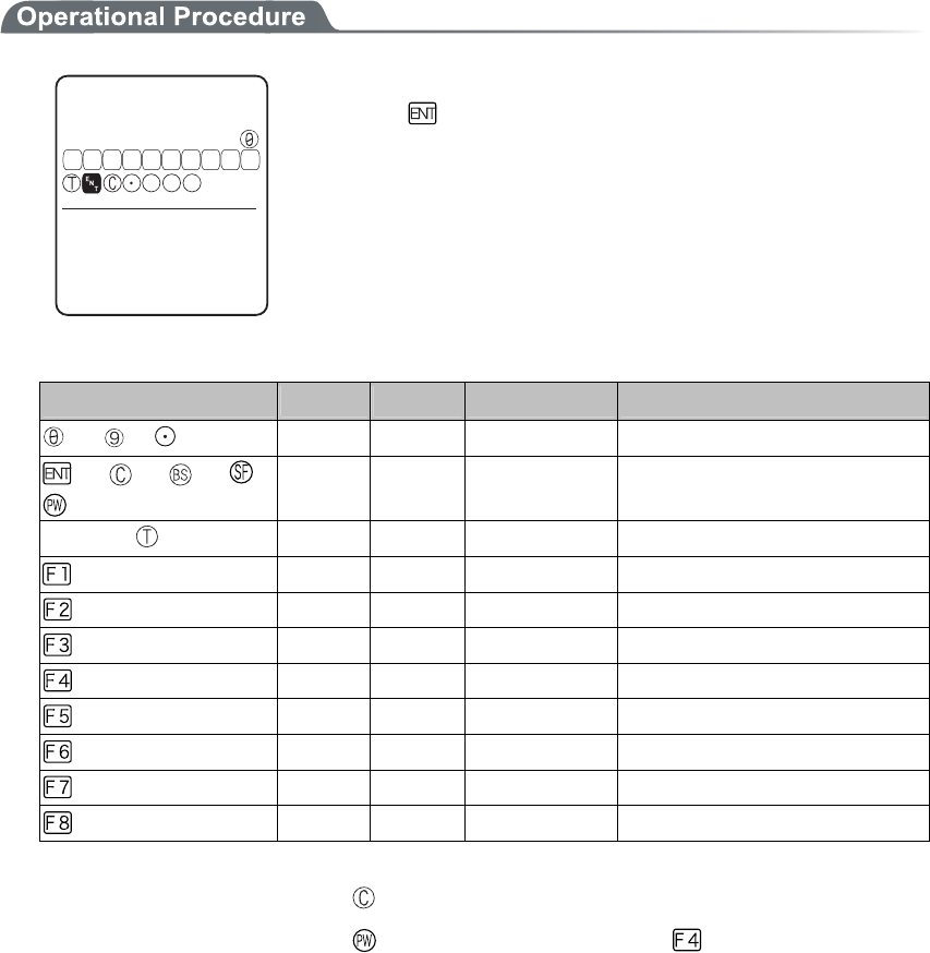
Chapter 3 System menu
3-94
3-16-5 Key
The key input test are performed with the indicator(buzzer/vibrator/LED/audio play) tests.
ḧḨḩḪḫḬḭḮḯǽ
-G[VGUV
ǽǽǽǽǽǽǽǽǽǽ
((((( ( ( (ᵉᵏ
29
5( $5
Press the key, and display the icon on the partition of the center got
Highlighted ( key only reversed), and the icon corresponds to the
key appears under the partition line (local eco). And the indicator
corresponding to each key operates.
The indicator assigned to each key is as follows.
Key Buzzer Vibrator LED Audio play
to , ○ × Green (SCAN) ×
, , , ,
○ × Red (ALRAM) ×
Scan key ( , F9, F10) × ○ Orange (SCAN) ×
× × Red (SCAN) Sound
× × Red (SCAN) Voice (Japanese)
× × Red (SCAN) Voice (Japanese)
× × Red (SCAN) Voice (Japanese)
× × Red (SCAN) Voice (Japanese)
× × Red (SCAN) Voice (Japanese)
× × Red (SCAN) Voice (Japanese)
× × Red (SCAN) Voice (Japanese)
The test will end when either the key is pressed twice, or all keys are pressed.
Such operations as power off by key or backlight adjustment by
key are enabled until all
tests have finished.

Chapter 4
4 FAQ (Frequently Asked Questions)

Chapter4 FAQ
4-2
4-1 FAQ
FAQ (Frequently Asked Questions)
This chapter lists frequently asked questions, problems and operations that need to be performed to solve prob-
lems, and reference pages for items in this manual.
Q: The power does not turn ON.
■ Is the battery pack equipped correctly?----(P.1-4)
■ Is the battery pack charged?----(P.1-21)
■ Aren't the battery pack electrodes dirty?----(P.1-22)
Q: Nothing is displayed on the screen.
■ Is the battery pack equipped correctly?----(P.1-4)
■ Is the battery pack charged?----(P.1-21)
■ Aren't the battery pack electrodes dirty?----(P.1-22)
<In the case where the items mentioned above have been
checked and the problem is still unsolved>
Please start the system menu using the following Method.
1. Remove the battery pack
2. Wait 10 seconds. Install the battery pack
3. Hold down the scan key then press the key.
Q: After not using for a while, the power is shut OFF.
■ Is the battery pack charged?----(P.1-21)
■ Hasn't the Auto-power-off function been set to start??----(P.3-21)
Q: It cannot charge.
■ Has the terminal been equipped with the charger correctly?
■ Has the charger been equipped with the battery pack correctly?
Please refer to "1-6 Charging Specification"(P.1-17).

4-1 FAQ
4-3
Q: The System Menu does not start.
■ Is the "application" set to "Auto execute"?----(P.3-15)
From the System menu, select "1:System setup", and then select "1:Auto execute" to set the
System menu for automatic launch.
■ To force the launch of the S
y
stem Menu, hold the scan ke
y
then press the
key.----(P.3-9)
Q: How do I change the application, which starts when the
power is turned ON?
From the System Menu, select "1:System", then "1:Auto execute " to set the desired application for
automatic launch. ----(P.3-15)
Q: How do I start another application?
From the System Menu"5:File", select "2:Application " then select "Execute" from "Sub
Menu" to run.----(P.3-51)
Q: The Barcode is not scanned successfully.
■ Does the scanned Barcode meet the Barcode settings set in the application?
Some application settings prohibit a specific kind of Barcode from being scanned.
■ Isn't a specular reflection occurring?----(P.1-15)
■ Is scanning distance correct?----(P.1-14)
■ Isn't the filter of the Barcode sensor dirty?
If the filter of the Barcode sensor is dirty, the Barcode may not be scanned correctly. Please
wipe the filter with a dry soft cloth.
■ Is the barcode of good quality?
If the barcode quality is bad, it may not scanned correctly, change the setting of the decode
level and scan again.
Q: How do I check the free area of a drive?
From the System Menu, select "8:Manage" , then Select "5:drive" to check the drive----(P.3-83)

Chapter4 FAQ
4-4
Q: I cannot perform wireless data communications.
■ Is the access point connected to the Ethernet LAN?
If the LAN cable has fallen out or a link is not established, some access points do not perform
wireless communications.
<When the ALARM LED lights ON>
■ Is terminal SSID setting the same as the access point SSID settings?----(P.3-22)
Please set the access point SSID and terminal SSID the same.
When the terminal SSID is set to "ANY" (blank), it may be unable to connect because of the
access point functions. Refer to the access point manual for more information.
■Is the authentication setup correct?----(P.3-28)
Please set the access point Authentication System and terminal Authentication System settings
the same.
If in "SHARED" mode, please check the WEP settings.
<When ALARM LED turns off or blinks>
■ Are the WEP settings the same?
Are the WEP keys the same? ("Null," "40bits," "128bits")
Do the WEP's Tx KEY_ID and the WEP key match? (P.3-25)
■ Doesn't an access point with a same channel or interfering channel exist?
In the case where a non-interfering channel is set, a maximum of 4 access points can be used
in the one area.
■Isn't the wireless transmission being interfered by an obstacle?
Please check whether there is no equipment, such as a microwave oven or other WLANs etc,
which can cause interference.
Also, since a computer may act as a noise generation source, move the access point and termi-
nal away from the computer (1m or more).
■ Aren't there any problems with the TCP/IP settings (IP address etc)?----(P.3-35)
Check it to see if the terminal can connect to the computer by using the ping command etc.
Q: I cannot perform Bluetooth communication.
■ Has the Remote device to be connected set as default device?----(P.3-66)
■ Are the Remote device to be connected and the Security setting identi-
cal?----(P.3-64)
■ Has the Remote device to be connected setup correctly?
・Does the Power turn ON?
・Is the connecting enabled?
■ Is the connecting procedure correct?
・Connect the PC and GTX-100 (P.1-9)
・Communication between the GTX-100 terminals (P.3-46~46)
・Bluetooth Clone (P.3-80)
・Bluetooth Test (P.3-90)

4-1 FAQ
4-5
Q: Can I use at the same time both WLAN and Bluetooth in the
same environment and on the same terminal?
You can use WLAN and Bluetooth at the same time, however the communication may be delayed
due to mutual interference between wirelesses.
Q: "Writing Failed" was displayed during transmission or re-
ception of a file.
■ This message is displayed when there is little space left on the F Drive.
Create some free space on the F drive by deleting unnecessary files then start again. If the free
space after deleting files is still too small to accommodate the file you want to store in the F
drive, you will have to perform defragmentation to reclaim fragmented space.---(P.3-83)
Q: "Time Out" was displayed during transmission or reception
of a file.
This ma
y
be displa
y
ed after a fixed period of time has passed while in the
transmission or reception waiting state.
■ Is the communication software running on the host computer?----(P.1-5)
■ Is the communication settings made correctly?----(P.1-5)
■ Are the GTX-100 and the host computer connected correctly?----(P.1-8)
■ Does the host computer have enough resources?
When applications other than the communication software are being used, the computer may
run out of resources and cause the file transmission and reception to fail. Close as many appli-
cations not needed for communication as possible, and then try again.
Q: "Connection Failed" was displayed during transmission or
reception of a file.
■ Have the communication setup for wireless communications and the network
setup been performed correctly?----(P.1-8)
■ Is the FTP server running on the host computer?
■ Are the access point (our recommended item) and computer connected cor-
rectly through the LAN circuit?----(P.1-8)
■ Have the FTP settings been made correctly? ----(P.3-38)
■ Has the BluePorter running on the host computer?
■ Is it connected to the other remote device than the targeted remote device?
■ Is the setup of the remote device and the security identical?
■ Has the terminal ID and Remote device been setup correctly?

Chapter4 FAQ
4-6
Q: I want to perform the setup of the terminal IP address etc. at
a time from a computer.
Automatic setup of a terminal can be performed by using the DHCP server function of the "
WebGlider-X "
Q: Starting an application or transmission/reception of a file
cannot be performed.
When the voltage level of the battery pack is low, the GTX-100 is unable to handle some functions.
Is the battery pack charged? ----(P.3-77)
Q: I suspect that the file is corrupt.
Either delete the file, or transmit the file to the host computer to recover the data. ----(P.3-52~3-55)
Q: "System Error" was displayed and after pressing a key, the
power turned OFF.
This is displayed when a system program is not able to specify the cause of an error. Possible causes
include failures in hardware, system program or application, external factors like strong static elec-
tricity, and user errors. If a system error message is displayed, the power will be shut off if key
is pressed. At the next startup, GTX-100 tries to restore as much as possible.
Please turn ON the power again.

Appendix. A
5 System Menu Factory Settings List

Appendix A System menu Factory Settings
A-2
Appendix. A-1 System menu Factory Settings
Parameters Possible Setting Range Factory Settings
Auto execute System menu or application System menu
Resume Enable, Disable Disable
Password Alphanumeric characters from 4 to 30, Up-
per-case character/Lower-case character are dis-
tinguished.
Auto wake up Specify any among “Month”, ”Week”, and ”Day”
Auto power off 0000, or 0060 to 3600(seconds) 0600 (seconds)
SSID Alphanumeric characters up to 32, Upper-case
character/Lower-case character are distinguished.
GTX
Roaming level Slow, Normal, Fast Normal
Doze mode Quick, 1 second, None 1 second
Encryption Method Disabled, WEP(40Bit), WEP(128Bit), TKIP,
CCMP(AES)
Disabled
WEP Tx keyID KEY-1, KEY-2, KEY-3, KEY-4 KEY-1
WEP key setting Setting the contents of each WEP key (1, 2, 3, 4).
Characters which can be used are "0" - "9", "A" -
"F" and "a" - "f." When a 40 bits is Selected for
"WEP," the WEP is a fixed 10 characters. When
128 bits is selected, it is a fixed 26 characters.
PSK(TKIP/CCMP) In ASCII characters, input the characters from 8
to 63. By 16 digit number, input up to 64 charac-
ters.
Authentication Method Open, Shared, EAP Open
EAP mode EAP-TLS, EAP-PEAP-MSCHAPv2 EAP-TLS
CA root Certificate Select a file
Client Certificate Select a file
Private key (File) Select a file
Private key (Password) Alphanumeric characters up to 31, Upper-case
character/Lower-case character are distinguished.
WLAN authentication user
name
Alphanumeric characters up to 62, Upper-case
character/Lower-case character are distinguished.
WLAN authentication Pass-
word
Alphanumeric characters up to 31, Upper-case
character/Lower-case character are distinguished.
At starting up authentication
Time out
15 to 120 60 seconds
Attention Display, Not Display Display
Rate control 11b Auto, 11bg Auto, 11g Auto, 11g 6 or 9M,
1Mbps, 2Mbps, 1Mbps or 2Mbps
Auto
RTS_Threshold 0000 to 2347 2347(bytes)

Appendix. A-1 System menu Factory Settings
A-3
Parameters Possible Setting Range Factory Settings
IP address Any value of IP address style 000.000.000.000
NetMask Any value of IP address style 000.000.000.000
Gateway Any value of IP address style 000.000.000.000
MTU 0064 to 1500 1500(octets)
DHCP Startup type Disabled, Application boot, System menu boot Disabled
DHCP Update protect IP address, NetMask, Gateway, ID (The plural
can be selected)
Not selected
DHCP Server port 00001 to 65534 08067
FTP Server address Method Address, Name Address
FTP Address Any value of IP address style 000.000.000.000
FTP Name Alphanumeric and symbol characters up to 62,
Upper-case character/Lower-case character are
distinguished.
FTP User name Alphanumeric and symbol characters up to 18,
Upper-case character/Lower-case character are
distinguished.
FTP Password Alphanumeric and symbol characters up to 20,
Upper-case character/Lower-case character are
distinguished.
FTP Server port 00001 to 65534 00021
FTP Mode Passive, Active Passive
FTP Current folder /(Root), /(User name), /(Specified) /(Root)
FTP Specified folder Alphanumeric characters up to 62, Upper-case
/Lower-case distinguished
DNS Primary Any value of IP address style 000.000.000.000
DNS Secondary Any value of IP address style 000.000.000.000
DNS Server port 00001 to 65534 00053
DNS Time out time 01 to 99 03(seconds)
DNS Trial count 0 to 9 1
Cache time 0000 to 9999 0003(min)
SNMP Community(R/Only)
Community name
Alphanumeric characters up to 16, Upper-case
/Lower-case distinguished
public
SNMP Community(R/Only)
Manager IP address
Any value of IP address style 000.000.000.000
SNMP Community(R/W)
Community name
Alphanumeric characters up to 16, Upper-case
/Lower-case distinguished
private
SNMP Community(R/W)
Manager IP address
Any value of IP address style 000.000.000.000
SNMP Trap Community name Alphanumeric characters up to 16, Upper-case
/Lower-case distinguished
Welcat
SNMP Trap Manager IP ad-
dress
Any value of IP address style 000.000.000.000

Appendix A System menu Factory Settings
A-4
Parameters Possible Setting Range Factory Settings
SNMP Authentication Trap Send, Not send Not send
SNMP Agent port 00001 to 65534 00161
SNMP Trapport 00001 to 65534 00162
ID 000 to 999 000
Barcode Trigger operation Normal, Double, Release, Auto Normal
Barcode Power saving Full, Quick, None Full
Barcode Irradiation time 00 to 60 20 (seconds)
Barcode Decode level Loose, Normal, Strict Normal
Key repeat delay 0000 or, from 0100 to 1000 0500(milliseconds)
Key repeat rate 0000 or, from 0100 to 1000 0100(milliseconds)
Bluetooth local device Device
name
Alphanumeric and symbol characters up to 30,
Upper-case /Lower-case distinguished
GTX-100
Bluetooth local device Pairing Enable, Disable Disable
Bluetooth local device PIN
code
16 digit characters (0 to 9, A to F) up to 16
Bluetooth Remote device 1 to 7
device name
Alphanumeric and symbol characters up to 30,
Upper-case /Lower-case distinguished
No name
Bluetooth Remote device 1 to 7
BD address
16 digit characters (0 to 9, A to F) up to 12 00:00:00:00:00:00
Bluetooth Remote device 1 to 7
Pairing
Enable, Disable Disable
Bluetooth Remote device 1 to 7
PIN code
16 digit characters (0 to 9, A to F) up to 16
Bluetooth Remote device sear-
choption
1 to 9 9
Display contrast Level 1 to 8 Level 4
Backlight Luminosity High, Low High
Volume Level 1 to 8 Level 8
Click Sound None, Beep, Beep + Audio, Audio None

Appendix. B
6 Sample Barcode
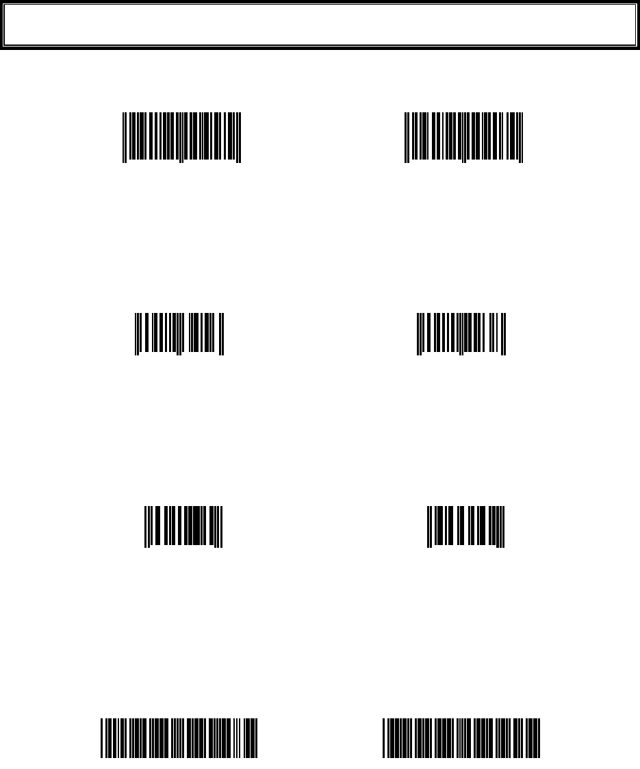
Appendix. B Sample Barcode
B-2
Appendix. B-1 Sample Barcode
■JAN13
4 994121 104579 4 994121 102070
■JAN8
4912 3456 4911 2238
■UPC-E
0001234 4 0999999 2
■CODE39(C/D)
*12345F*
*ABCDEH*
(notes) It is not likely to be able to read because of low printing quality (Expansion, Reduction, Dirt, etc.).

Appendix. B-1 Sample Barcode
B-3
■CODE39(No C/D)
*123456*
*ABCDEF*
■NW-7(C/D)
a123456$a
b-$/456/0b
■NW-7(No C/D)
c567890c
d:/+789d
■NW-7(HEX)
a A B C D E F a
b D E F A B C b
(notes) It is not likely to be able to read because of low printing quality (Expansion, Reduction, Dirt, etc.).

Appendix. B Sample Barcode
B-4
■ITF(C/D)
1234567895
9876543215
■ITF(No C/D)
1234567890
9876543210
■ITF(Standard ITF-14)
04912345678904
11223344556675
■ITF(Extended ITF-16)
0104903333049409
1122334455667784
(notes) It is not likely to be able to read because of low printing quality (Expansion, Reduction, Dirt, etc.).

Appendix. B-1 Sample Barcode
B-5
■ITF(Add on version ITF-6)
123457
112239
■CODE128(Code set A)
123456
ABCDEF
■CODE128(Code set B)
abcdef
!"#$%&'()
■CODE128(Code set C)
012345678901
112233445566778899
(notes) It is not likely to be able to read because of low printing quality (Expansion, Reduction, Dirt, etc.).

Appendix. B Sample Barcode
B-6
■EAN128(Code set A)
(01)14530825000013(17)001231
■EAN128(Code set B)
(06)17458663525300(143)543210
■EAN128(Code set C)
(10)13589645123004(48)468125
(notes) It is not likely to be able to read because of low printing quality (Expansion, Reduction, Dirt, etc.).

7 Index
Index
I-2
Index
A
Access point................................................. xiv, 1-7
Access point search........................................... 3-85
Active mode......................................................3-38
Ad-hoc mode....................................................... 1-7
Advanced (FTP)................................................ 3-37
Advanced (SNMP)............................................3-42
Advanced(WLAN Security).............................. 3-31
Advanced(WLAN)............................................ 3-31
ALARM LED .....................................................1-2
AP search .......................................................... 3-85
Application program ........................................... 2-2
At starting up authentication Time out (Factory
settings).......................................................... A-2
Attention ........................................................... 3-31
Attention (Factory settings) ............................... A-2
Authentication Method .....................................3-28
Authentication Method (Factory settings).......... A-2
Auto execute ..................................................... 3-15
Auto execute (Factory settings) ......................... A-2
Auto power off .................................................. 3-21
Auto power off (Factory settings) ...................... A-2
Auto wake up .................................................... 3-20
Schedule clear ............................................. 3-21
Schedule confirmation................................. 3-20
Schedule setting........................................... 3-20
Auto wake up (Factory settings) ........................ A-2
Auto-power-off function ..................................... 4-2
B
Back space key....................................................1-3
Backlight Luminosity........................................ 3-68
Backlight Luminosity (Factory settings)............ A-4
Backup battery .................................. xiv, 1-20, 1-21
Barcode ............................................................. 3-56
Barcode Decode level (Factory settings) ........... A-4
Barcode Irradiation time (Factory settings) ....... A-4
Barcode Power saving (Factory settings)........... A-4
Barcode Trigger operation (Factory settings)..... A-4
Barcode window ................................................. 1-2
Battery Alert........................................................3-8
Battery cover....................................................... 1-3
Battery cover lock lever ...................................... 1-3
Battery for Backup............................................1-23
Battery level...............................................3-8, 3-74
Battery pack ......................... xiv, 1-3, 1-4, 1-16, 4-2
charging....................................................... 1-18
Installing...................................................... 1-21
Removing .................................................... 1-20
Replacing..................................................... 1-21
Worn out...................................................... 1-21
BluePorter .................................................... xiv, 1-5
Bluetooth local device Device name (Factory
settings).......................................................... A-4
Bluetooth local device Pairing (Factory settings)
....................................................................... A-4
Bluetooth local device PIN code (Factory settings)
....................................................................... A-4
Bluetooth Remote device 1 to 7 BD address
(Factory settings) ........................................... A-4
Bluetooth Remote device 1 to 7 device name
(Factory settings) ........................................... A-4
Bluetooth Remote device 1 to 7 Pairing (Factory
settings).......................................................... A-4
Bluetooth Remote device 1 to 7 PIN code (Factory
settings).......................................................... A-4
Bluetooth Remote device searchoption (Factory
settings).......................................................... A-4
Broken file ........................................................ 3-53
C
CA root certificate............................................. 3-29
CA root Certificate (Factory settings)................ A-2
Cache time (Factory settings) ............................ A-3
Cancellation key ................................................. 1-2
Certificate file ................................................... 3-29
Charger.............................................................. 1-16
Charging.....................................................1-16, 4-2
Battery pack ................................................ 1-17
Charging Error .................................................. 1-18
Charging jack...................................................... 1-3
Charging specification ...................................... 1-16
Click Sound (Factory settings)........................... A-4
Client Certificate............................................... 3-29
Client Certificate (Factory settings)................... A-2
Clock................................................................. 3-16
current time ................................................. 3-16
Manual setting............................................. 3-16
Server setting............................................... 3-16
Clone................................................................. 3-77
CODE128(Code set A) (Sample Barcode)......... B-5
CODE128(Code set B) (Sample Barcode)......... B-5
CODE128(Code set C) (Sample Barcode)......... B-5
CODE39 (C/D) (Sample Barcode) .................... B-2
CODE39 (No C/D) (Sample Barcode)............... B-3
Common key..................................................... 3-25
Community(R/Only)......................................... 3-40
Community(R/W) ............................................. 3-41
Contrast............................................................. 3-68
Current time ...................................................... 3-16

Index
I-3
D
Data communication Method
Bluetooth communications............................1-9
WLAN communications................................ 1-8
Data communication/preparation of
Bluetooth communication .............................1-8
WLAN communication ................................. 1-7
Data storage ...............................................1-22, 2-2
Dead Zone......................................................... 1-14
Decode level...................................................... 3-59
Dedicated charger .............................................1-16
Default device ..................................................... xiv
Default gateway .............................................. 3-34
Device Registry................................................... 3-2
DHCP................................................................ 3-34
DHCP client function........................................ 3-34
DHCP Execute .................................................. 3-35
DHCP Request .................................................... 3-9
DHCP Server port (Factory settings) ................. A-3
DHCP Startup type (Factory settings)................ A-3
DHCP Update protect (Factory settings)............ A-3
Direction key..................................................... 3-61
Display contrast (Factory settings)..................... A-4
Display of ALARM LED (during wireless
communications)........................................... 1-12
Display of SCAN LED (during terminal charging)
...................................................................... 1-12
DNS .................................................................. 3-39
DNS Primary (Factory settings)......................... A-3
DNS Secondary (Factory settings)..................... A-3
DNS Server port (Factory settings).................... A-3
DNS Time out time (Factory settings) ............... A-3
DNS Trial count (Factory settings) .................... A-3
Doze mode ........................................................ 3-23
Doze mode (Factory settings) ............................ A-2
Drive .................................................................3-80
E
EAN128(Code set A) (Sample Barcode) ........... B-6
EAN128(Code set B) (Sample Barcode) ........... B-6
EAN128(Code set C) (Sample Barcode) ........... B-6
EAP mode (Factory settings) ............................. A-2
EAP setting ....................................................... 3-28
EAP-PEAP-MSCHAPv2 .................................. 3-29
EAP-TLS ..........................................................3-29
Electrodes /cleaning .......................................... 1-21
Encryption......................................................... 3-24
Encryption Method ........................................... 3-24
Encryption Method (Factory settings)................ A-2
Enter key ............................................................. 1-2
Extension ...................................................2-3, 3-47
F
F drive ................................................. xiv, 1-22, 2-2
F10 key ...............................................................1-2
F9 key ................................................................. 1-2
File name ............................................................ 2-3
File receiving .................................................... 3-44
Folder................................................................ 3-38
FTP ................................................................... 3-36
FTP Address (Factory settings).......................... A-3
FTP Current folder (Factory settings) ................ A-3
FTP Mode (Factory settings) ............................. A-3
FTP Name (Factory settings) ............................. A-3
FTP Password (Factory settings) ....................... A-3
FTP Server address Method (Factory settings) .. A-3
FTP Server port (Factory settings)..................... A-3
FTP Specified folder (Factory settings) ............. A-3
FTP User name (Factory settings)...................... A-3
Function keys...................................................... 1-2
G
Gateway .......................................................... 3-34
Gateway (Factory settings) ................................ A-3
H
Hand strap........................................................... 1-3
Handy5250...................................................1-5, 2-2
Hardware device ............................................... 3-56
Hardware device testing.................................... 3-82
GTB-1 ........................................................ xiv, 1-20
Host name ......................................................... 3-36
I
ID ...................................................................... 3-55
ID (Factory settings) .......................................... A-4
Inclination of a Barcode.................................... 1-14
Indicator............................................................ 3-69
Indicator function.............................................. 3-69
Infrastructure mode............................................. 1-7
Initialize ............................................................ 3-75
IP address........................................................ 3-34
IP address (Factory settings) .............................. A-3
ITF (C/D) (Sample Barcode) ............................. B-4
ITF (No C/D) (Sample Barcode) ....................... B-4
ITF(Add on version ITF-6) (Sample Barcode) .. B-5
ITF(Extended ITF-16) (Sample Barcode).......... B-4
ITF(Standard ITF-14) (Sample Barcode)........... B-4
J
JAN13 (Sample Barcode) .................................. B-2
JAN8 (Sample Barcode) .................................... B-2
K
Key...................................................................... 3-3
Key Character assigns......................................... 3-4
Key Click Sound............................................... 3-73
Key repeat delay (Factory settings) ................... A-4

Index
I-4
Key repeat rate (Factory settings) ...................... A-4
KEY setting..................................................... 3-25
L
Laser light irradiation angle .............................. 1-13
LCD ....................................................................1-2
Local device............................................... xiv, 3-62
Luminosity ........................................................ 3-68
M
MAC address .................................................... 3-32
Manual setting(Clock)....................................... 3-16
Margin............................................................... 1-15
Memory Back Up
Backup battery............................................. 1-23
Battery pack................................................. 1-22
MTU................................................................ 3-34
MTU (Factory settings)...................................... A-3
Multi Charger...........................................1-16, 1-18
N
NetMask.......................................................... 3-34
NetMask (Factory settings)................................ A-3
Network setting.................................................3-33
NW-7 (C/D) (Sample Barcode).......................... B-3
NW-7 (HEX) (Sample Barcode) ........................ B-3
NW-7 (No C/D) (Sample Barcode).................... B-3
O
Open authentication ..........................................3-28
OS version......................................................... 3-75
P
Passive mode..................................................... 3-38
Password ........................................................... 3-18
Clear ............................................................ 3-19
Setting .........................................................3-19
Password (Factory settings) ............................... A-2
Password (FTP)................................................. 3-37
Pitch .................................................................. 1-14
Power Switch ...................................................... 1-2
Private key ........................................................ 3-30
Private key (File) (Factory settings)................... A-2
Private key (Password) (Factory settings).......... A-2
Product plate .......................................................1-3
Product specifications ....................................... 1-10
Prolonged storage.............................................. 3-81
Battery ......................................................... 1-24
Terminal ...................................................... 1-24
PSK-TKIP......................................................... 3-26
PSK-TKIP (Factory settings) ............................. A-2
Q
GTC-1............................................................... 1-16
GTC-2......................................................1-16, 1-18
R
Rate control....................................................... 3-32
Rate control (Factory settings)........................... A-2
Readable angle.................................................. 1-14
Receive Method ................................................ 3-45
Receiving .......................................................... 3-44
Registry............................................................... 3-2
Remote device............................................ xiv, 3-64
Resume ............................................................. 3-17
Disabled....................................................... 3-18
Enabled........................................................ 3-17
Fail .............................................................. 3-17
Resume (Factory settings).................................. A-2
Resume function ............................................... 1-25
Reverse Barcode ............................................... 3-60
Roaming level................................................... 3-23
Roaming level (Factory settings) ....................... A-2
RTS Threshold .................................................. 3-32
RTS Threshold (Factory settings) ...................... A-2
S
S drive................................................. xiv, 1-22, 2-2
Scan depth......................................................... 1-13
Scan key....................................................... xiv, 1-2
SCAN LED.......................................1-2, 1-12, 1-16
Scanning angle.................................................. 3-60
Scanning Specifications.................................... 1-13
Screen ........................................................3-68, 4-2
Screen output characters
double-byte characters................................. 1-26
single-byte characters.................................. 1-27
Security (WLAN) ............................................. 3-24
Security Registry................................................. 3-2
Serial number seal............................................... 1-3
Server address................................................... 3-36
Server port (DHCP) .......................................... 3-35
Server port (FTP) .............................................. 3-38
Server setting(Clock) ........................................ 3-16
Setting Wizard................................................... 3-10
Shared key authentication ................................. 3-28
Shift key.............................................................. 1-3
Single Charger .................................................. 1-16
Skew ................................................................. 1-14
SNMP ......................................................3-40, 3-42
SNMP Agent port (Factory settings).................. A-4
SNMP Authentication Trap (Factory settings) ... A-4
SNMP Community(R/Only) Community name
(Factory settings) ........................................... A-3
SNMP Community(R/Only) Manager IP address
(Factory settings) ........................................... A-3
SNMP Community(R/W) Community name
(Factory settings) ........................................... A-3

Index
I-5
SNMP Community(R/W) Manager IP address
(Factory settings) ........................................... A-3
SNMP Trap Community name (Factory settings)
....................................................................... A-3
SNMP Trap Manager IP address (Factory settings)
....................................................................... A-3
SNMP Trapport (Factory settings) ..................... A-4
Software.............................................................. 2-2
Sound .......................................................3-56, 3-69
Sound volume ...................................................3-69
Speaker................................................................ 1-3
Specular reflection ............................................ 1-14
SSID..................................................................3-22
SSID (Factory settings)...................................... A-2
Startup type ....................................................... 3-35
Subnet mask.................................................... 3-34
Supported audio file.......................................... 3-47
Supported bitmap file........................................ 3-47
System menu.......................... xiv, 2-2, 2-4, 3-2, 4-3
Standard Operation........................................3-5
Startup ........................................................... 3-9
System menu factory settings............................. A-2
System menu List.............................................. 3-13
System program ........................................... xiv, 2-2
System Registry .................................................. 3-2
System version.................................................. 3-75
T
TCP/IP ..............................................................3-33
Temporary file..................................................... 2-3
Terminal .............................................................. xiv
Test (Barcode)................................................... 3-87
Test (Bluetooth)................................................. 3-86
Test (Display).................................................... 3-89
Test (Indicator).................................................. 3-90
Test (Key).......................................................... 3-90
Test (WLAN) .................................................... 3-82
Tilt..................................................................... 1-15
Trap ................................................................... 3-43
Trap setup..........................................................3-41
Trigger mode..................................................... 3-57
TxKey_ID ....................................................... 3-25
U
Unfilled space ................................................... 1-15
Unique Registry .................................................. 3-2
UPC-E (Sample Barcode) .................................. B-2
Update protect................................................... 3-35
User name ......................................................... 3-37
User Registry ...................................................... 3-2
V
Vibrator ............................................................. 3-69
Volume.............................................................. 3-69
Volume (Factory settings) .................................. A-4
W
WebGlider-X......................................... xiv, 1-5, 2-2
WebGlider-X browser ......................................... xiv
Welcat Enterprise MIB...................................... 3-42
Well known port (DHCP) ................................. 3-35
Well known port(FTP) ...................................... 3-38
WEP.................................................................. 3-25
WEP key ........................................................... 3-25
WEP key setting (Factory settings).................... A-2
WEP Tx keyID (Factory settings)...................... A-2
Wireless function ................................................ 1-6
Wireless LAN ................................................... 3-22
Wizard......................................................3-10, 3-81
WLAN ................................................ xiv, 1-7, 3-22
WLAN authentication Password (Factory settings)
....................................................................... A-2
WLAN authentication user name (Factory settings)
....................................................................... A-2
WLAN/ping testing........................................... 3-84
X
GTX-100's Software ........................................... 2-2

Wireless Handy Terminal
GTX-100
Hardware/System Menu
August, 2007 Manual Rev.1.0
Copyright©2007 Welcat Inc.
http://www.welcat.co.jp/
info@welcat.co.jp
M01GTX-100