Welcat GTX221G Wireless 2D-code Handy Terminal User Manual
Welcat, Inc. Wireless 2D-code Handy Terminal
UserManual.wiki
>
Welcat
>
GTX221G User Manual
User Manual
Navigation menu
Upload a User Manual
Namespaces
Wiki Guide
HTML
PDF
Info
Views
User Manual
Discussion / Help
Navigation

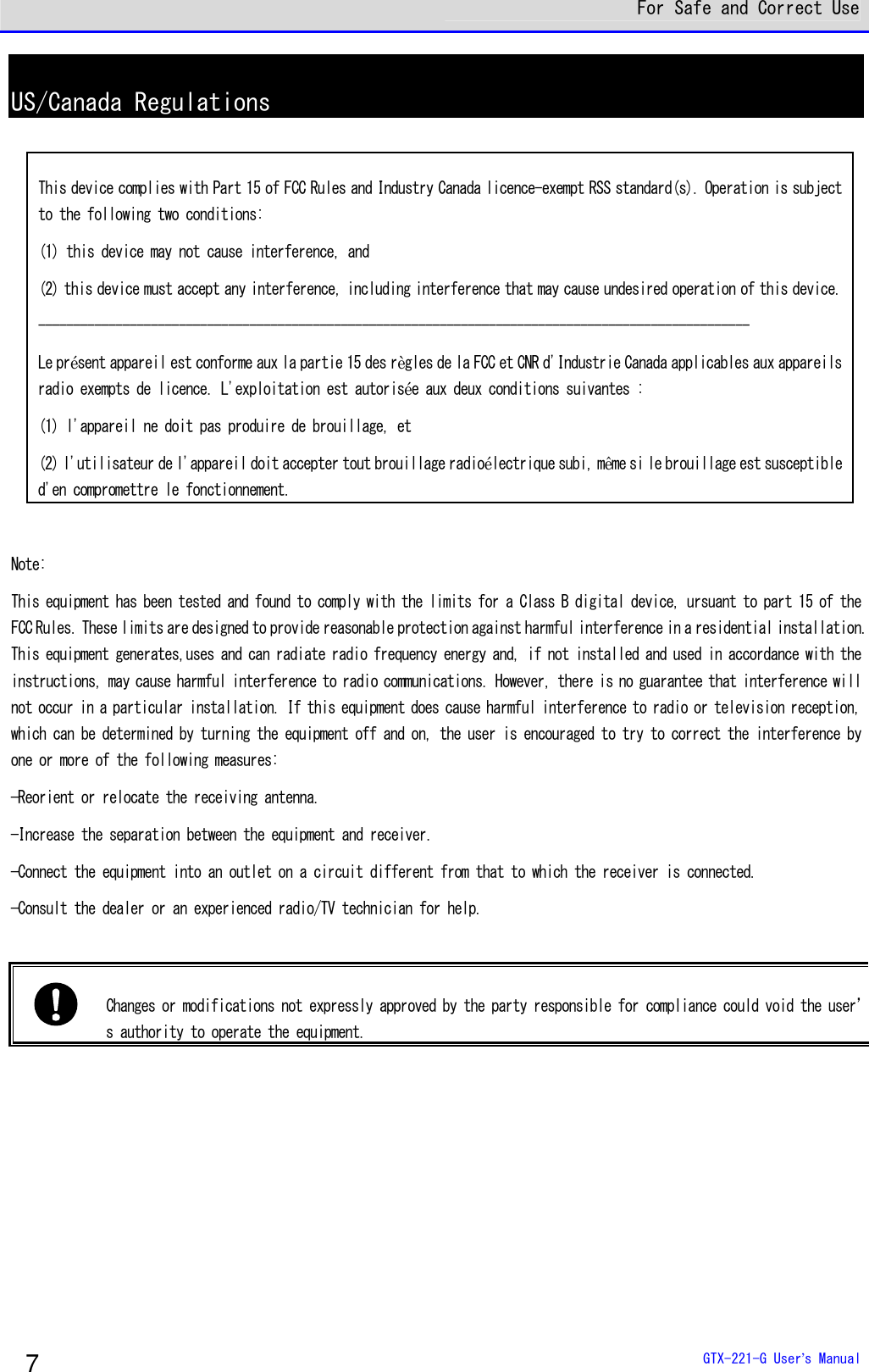
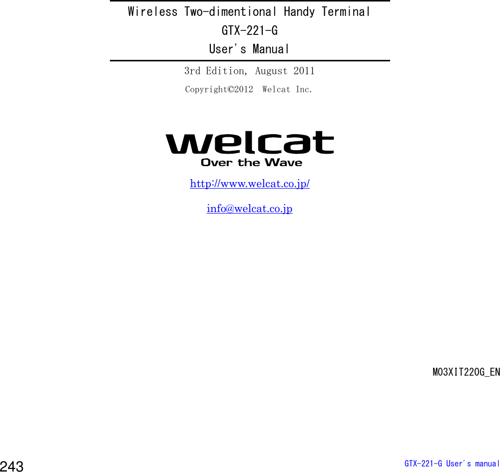
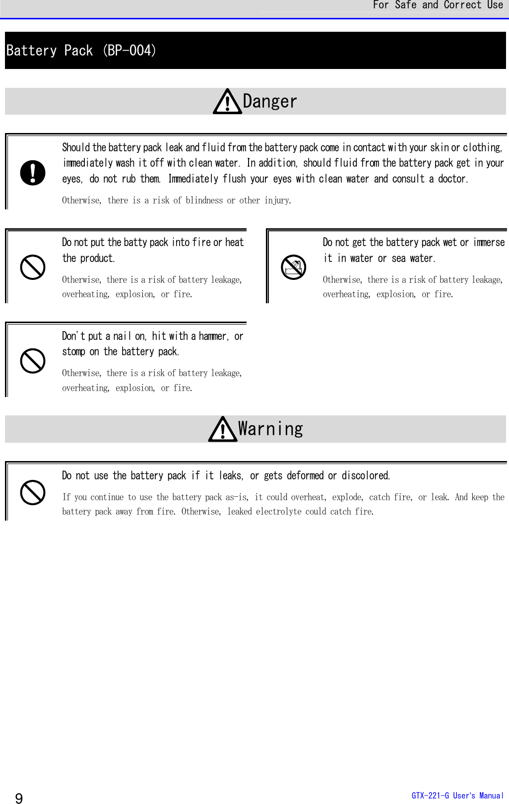
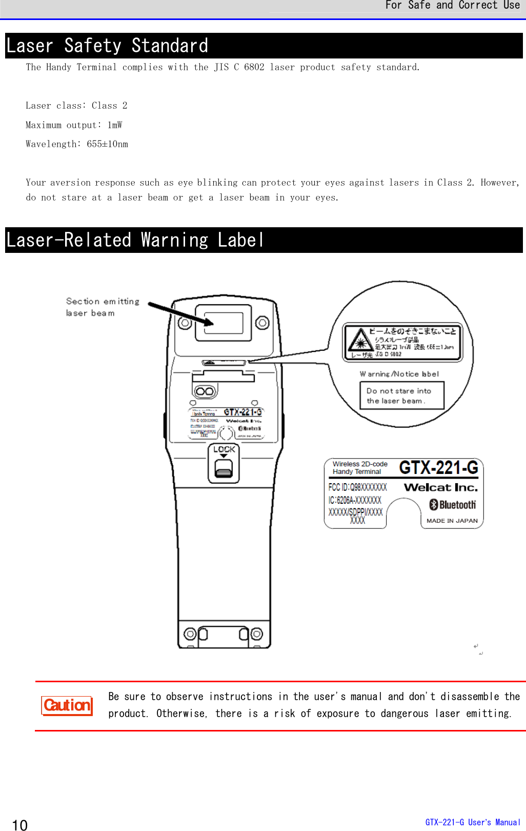
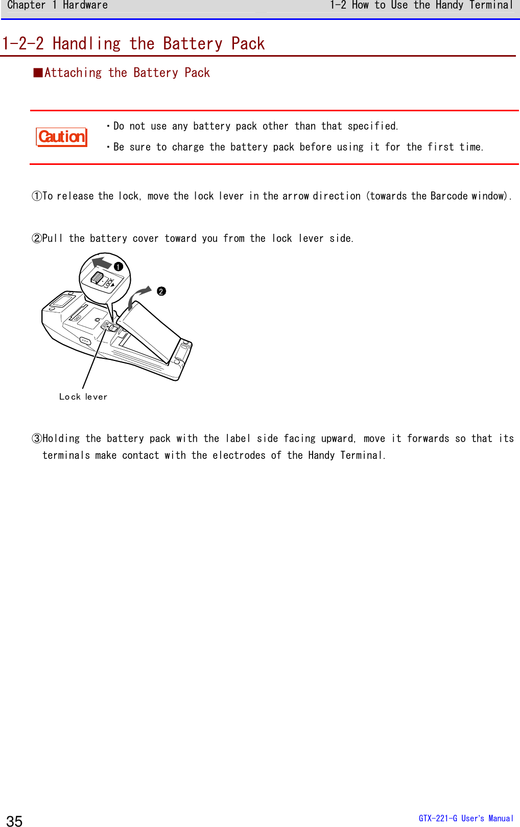
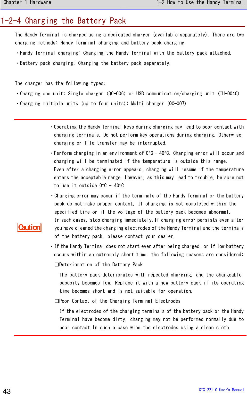
![For Safe and Correct Use GTX-221-G User’s Manual 8 RF Exposure Compliance The available scientific evidence does not show that any health problems are associated with using low power wireless devices. There is no proof, however, that these low power wireless devices are absolutely safe. Low power Wireless devices emit low levels of radio frequency energy (RF) in the microwave range while being used. Whereas high levels of RF can produce health effects (by heating tissue), exposure of low-level RF that does not produce heating effects causes no known adverse health effects. Many studies of low-level RF exposures have not found any biological effects. Some studies have suggested that some biological effects might occur, but such findings have not been confirmed by additional research. [Wireless 2D-code Handy Terminal (GTX-221-G)] has been tested and found to comply with FCC/IC radiation exposure limits set forth for an uncontrolled environment and meets the FCC radio frequency (RF) Exposure Guidelines in Supplement C to OET65 and RSS-102 of the IC radio frequency (RF) Exposure rules. Les connaissances scientifiques dont nous disposons n’ont mis en évidence aucun problème de santé associé à l’usage des appareils sans fil à faible puissance. Nous ne sommes cependant pas en mesure de prouver que ces appareils sans fil à faible puissance sont entièrement sans danger. Les appareils sans fil à faible puissance émettent une énergie radioélectrique (RF) très faible dans le spectre des micro-ondes lorsqu’ils sont utilisés. Alors qu’une dose élevée de RF peut avoir des effets sur la santé (en chauffant les tissus), l’exposition à de faibles RF qui ne produisent pas de chaleur n’a pas de mauvais effets connus sur la santé. De nombreuses études ont été menées sur les expositions aux RF faibles et n’ont découvert aucun effet biologique. Certaines études ont suggéré qu’il pouvait y avoir certains effets biologiques, mais ces résultats n’ont pas été confirmés par des recherches supplémentaires. [Wireless 2D-code Handy Terminal (GTX-221-G)] a été testé et jugé conforme aux limites d’exposition aux rayonnements énoncées pour un environnement non contrôlé et respecte les règles les radioélectriques (RF) de la FCC lignes directrices d'exposition dans le Supplément C à OET65 et d’exposition aux fréquences radioélectriques (RF) CNR-102 de l’IC.](https://usermanual.wiki/Welcat/GTX221G/User-Guide-1799364-Page-9.png)
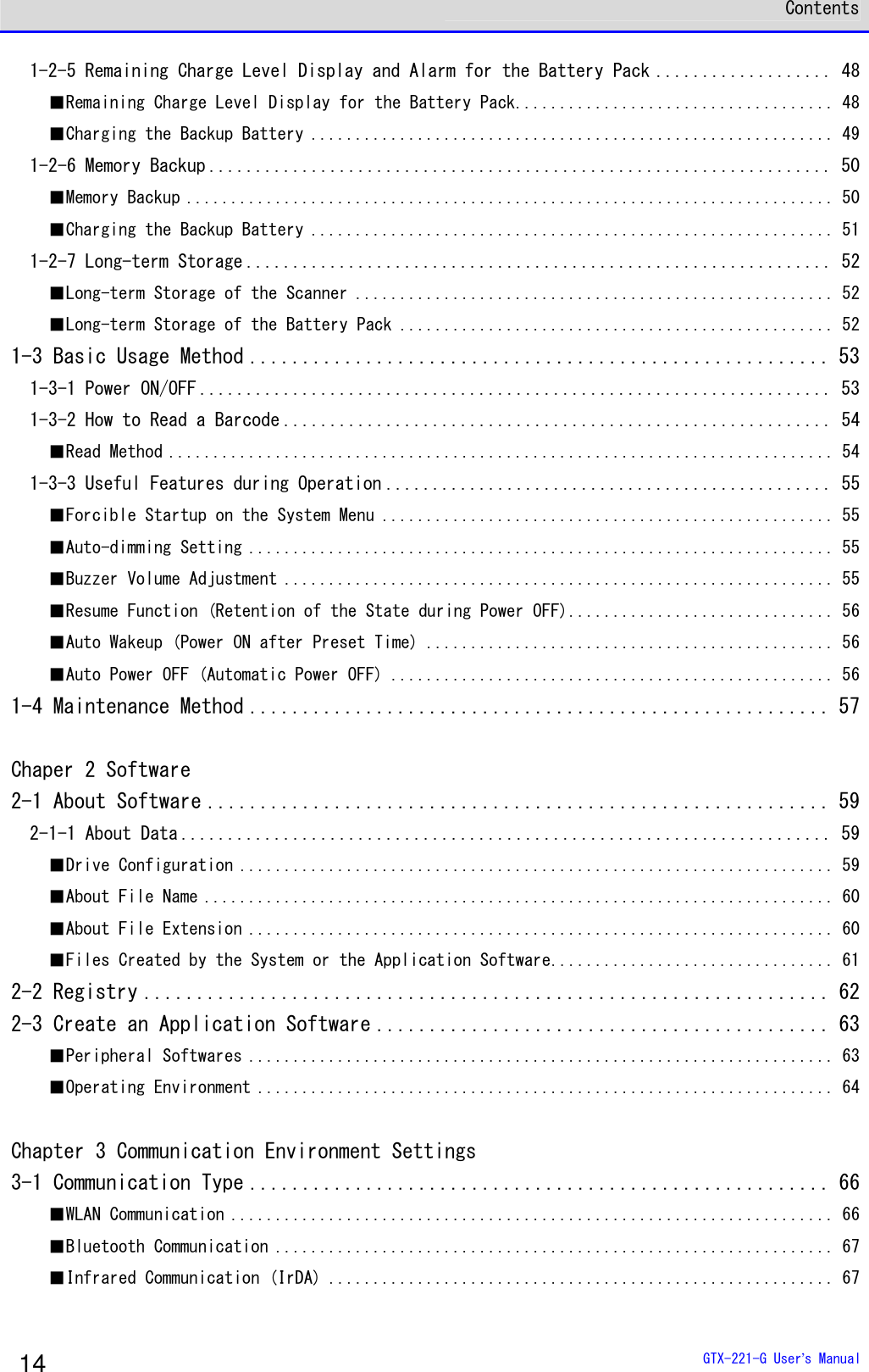
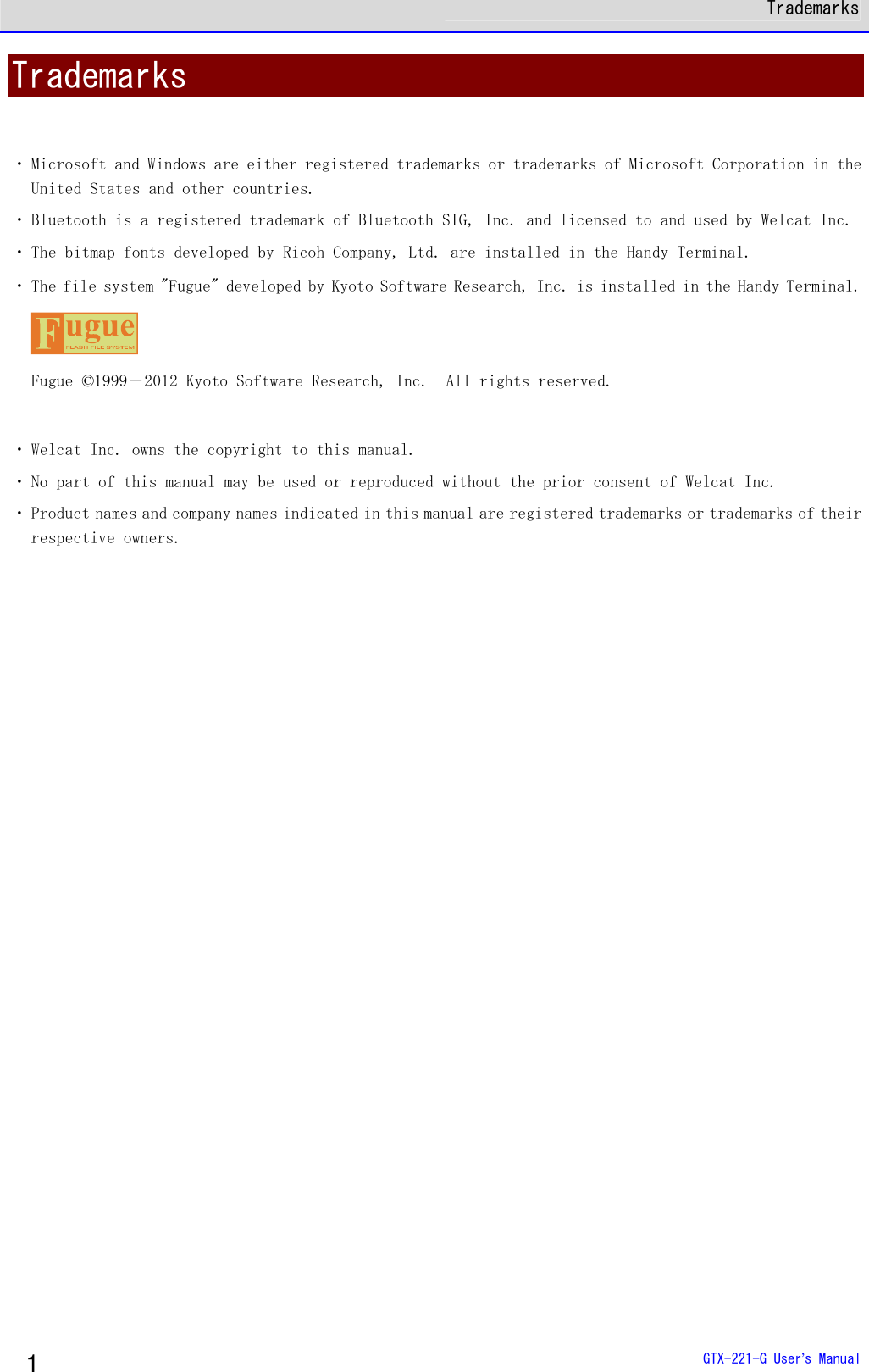
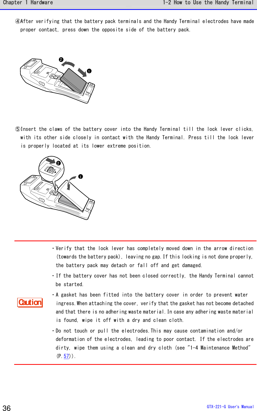
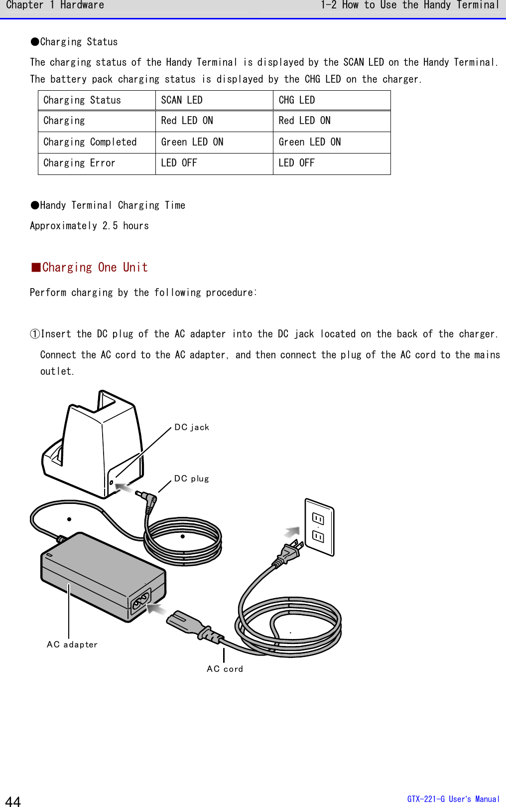
![Summary of This Manual GTX-221-G User’s Manual 20 ■Notes on Symbols, Terms, and Manual Conventions In this manual, the following symbols, terms, and conventions are used: Caution Describes items to be observed by the user and precautions when operating the product. Carefully read the desription indicated by this symbol and be sure to observe the instructions. Hint Describes useful information and tips. rrrreeeeffff Introduces pages describing related information or other manuals. Product/main unit Means the GTX-221-G main unit. 【 】 key Names of keys on the control panel are described using 【 】. Example: the 【PW】 key [ ] UIs displayed on screen are described using [ ]. Example: [System Menu] Explains how to operate the system menu. Some operation on the system menu is restricted when the battery pack level is lower than the specified value (which depends on the operation) at the time of execution. This symbol is used to explain how to perform operation in such cases. DHCP For some operation on the system menu, the settings can be collectively made from your PC using the DHCP client function. This symbol is used for how to operate the DHCP client function in such cases.](https://usermanual.wiki/Welcat/GTX221G/User-Guide-1799364-Page-21.png)

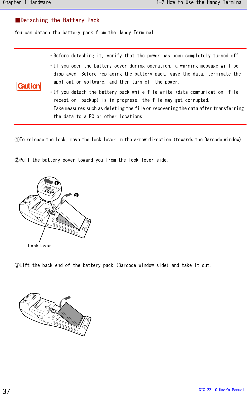
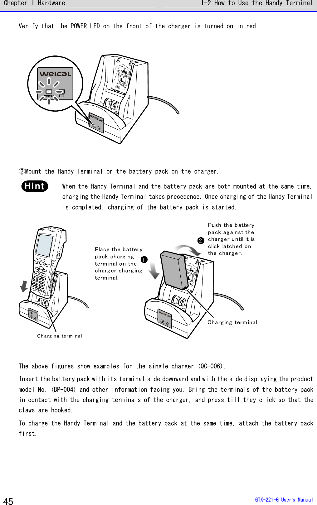
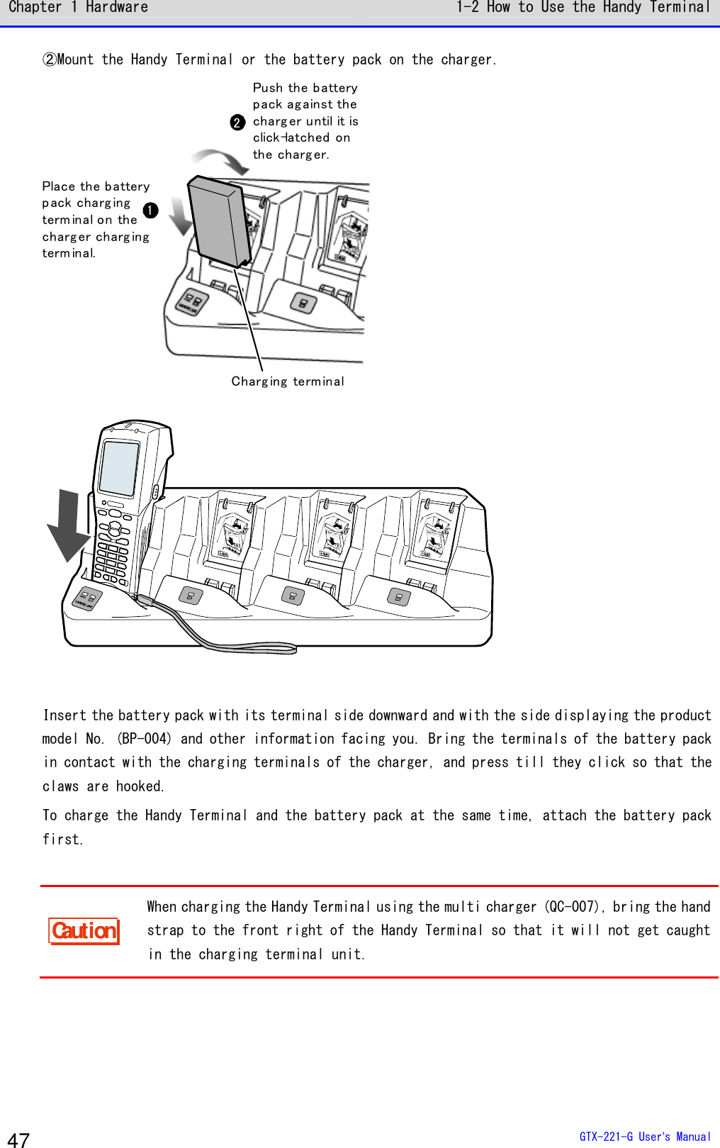
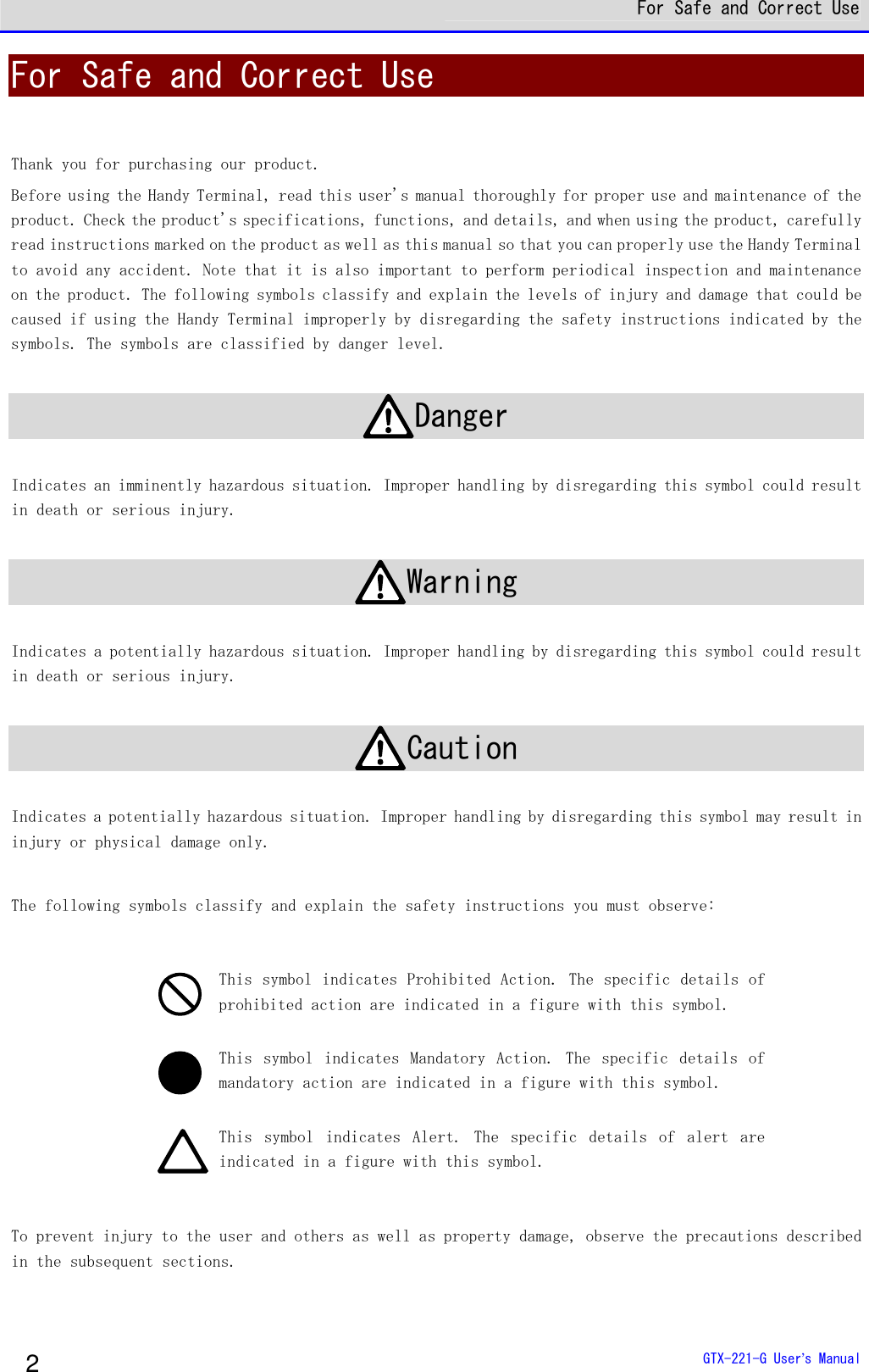
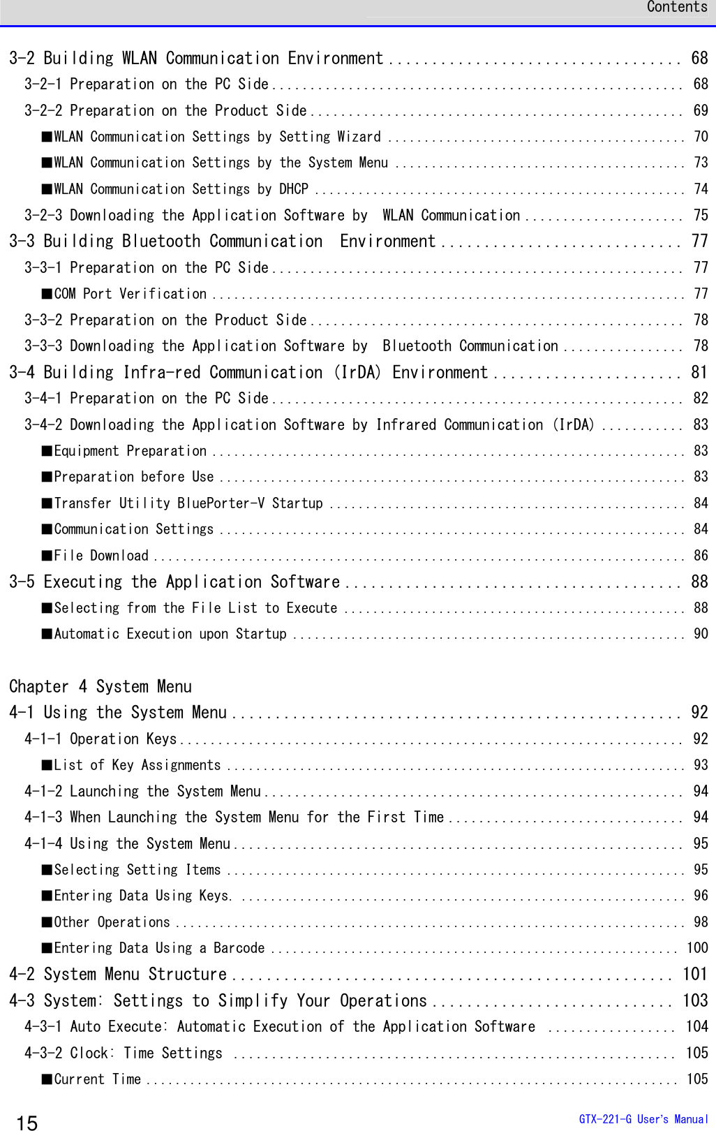
![Chapter 1 Hardware 1-2 How to Use the Handy Terminal GTX-221-G User’s Manual 49 ●Limitations when the remaining battery pack power becomes insufficient Some operations of the system menu are disabled and the following screen is displayed, when the remaining battery pack power icon shows one bar or no bars (varies depending on the operations). < File list >< Low-battery >Battery voltageis low.Therefore theoperation cannotbe executed.OK This manual displays the disabled operations using . ●Low Battery Display After the remaining battery pack power icon displays empty (no bars), if the voltage falls even lower, the following screen is displayed, and the power is forcibly turned off after ap-proximately five seconds. [ Battery Alert ]Voltage is low.Please charge it. ■Charging the Backup Battery The Handy Terminal has a built-in backup battery for backing up the system information. Charge the backup battery using the following procedure: ①Prepare a fully charged battery pack. ②As soon as the battery pack is attached to the Handy Terminal, the backup battery starts to be charged. If the backup battery has been completely depleted, charging requires at least 24 hours.During this time, do not detach the battery pack.](https://usermanual.wiki/Welcat/GTX221G/User-Guide-1799364-Page-50.png)
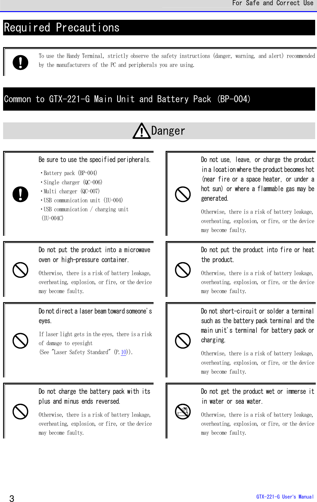
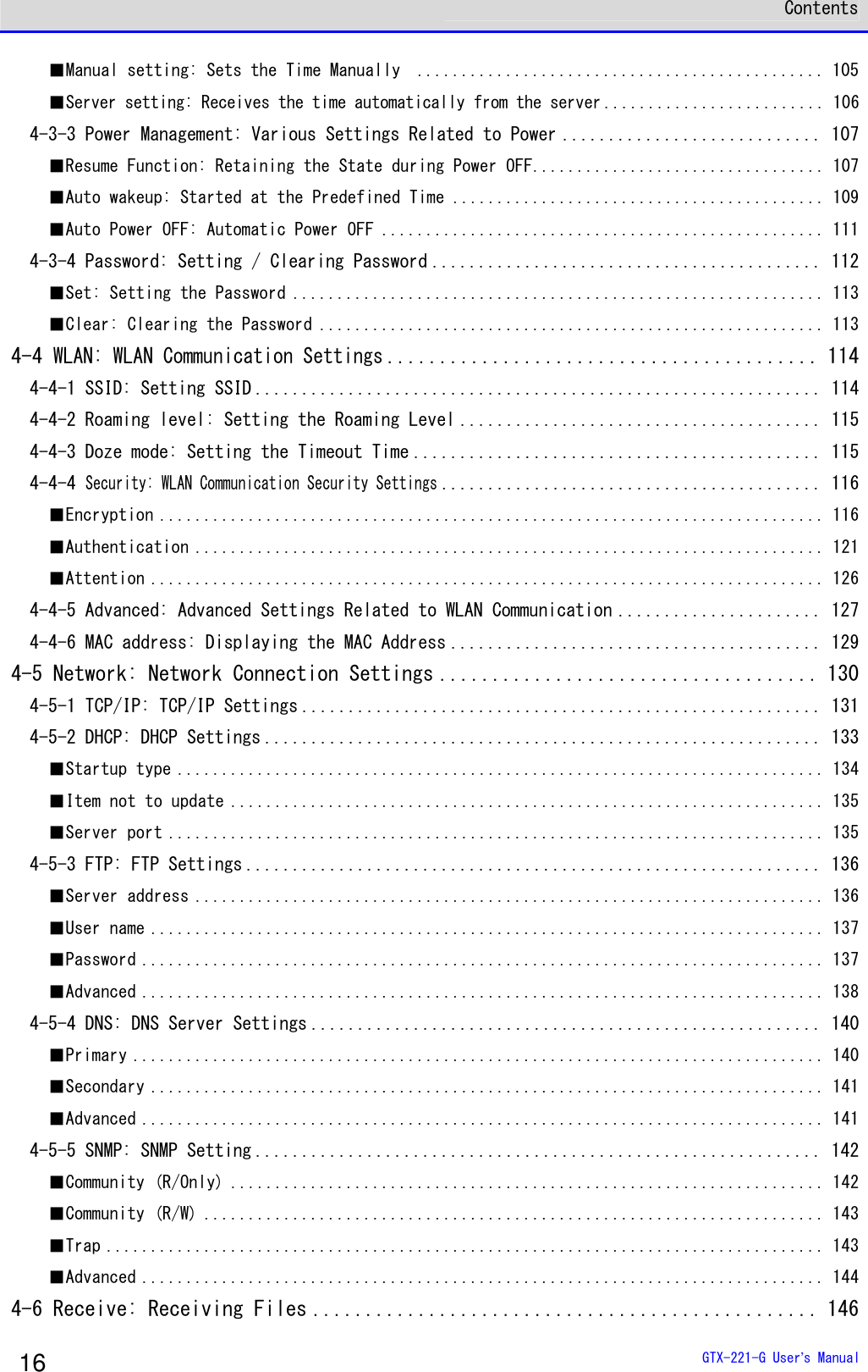
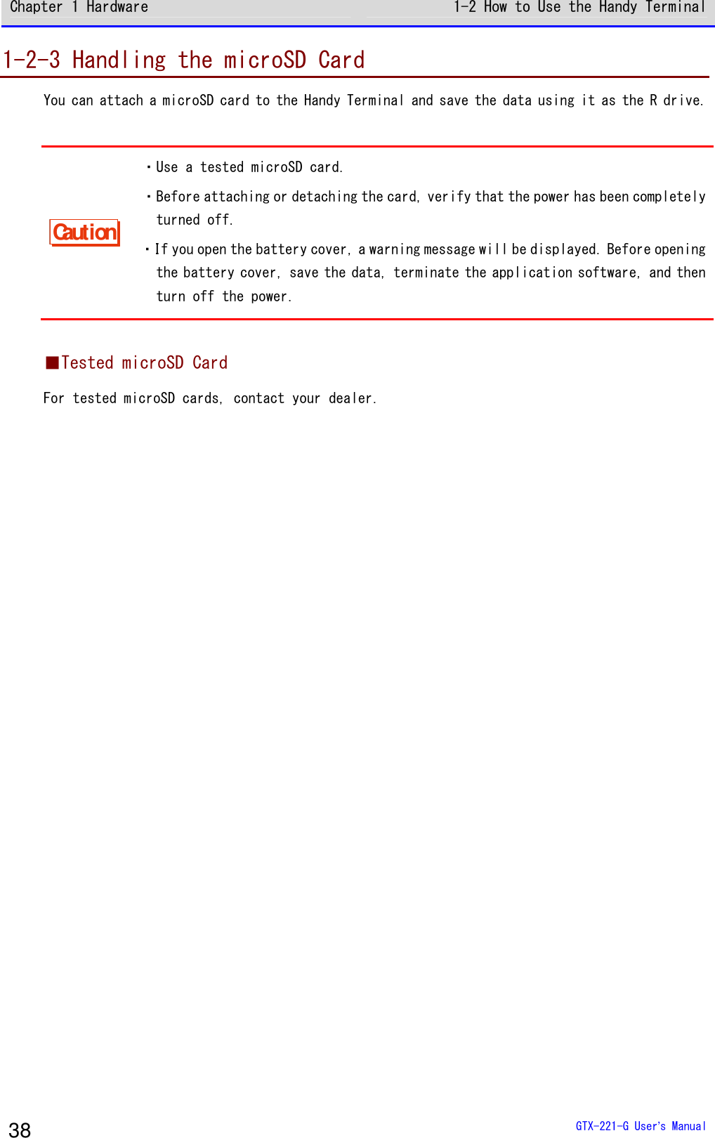
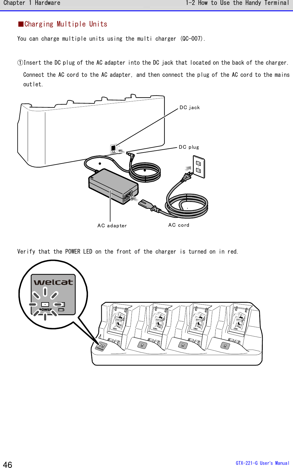
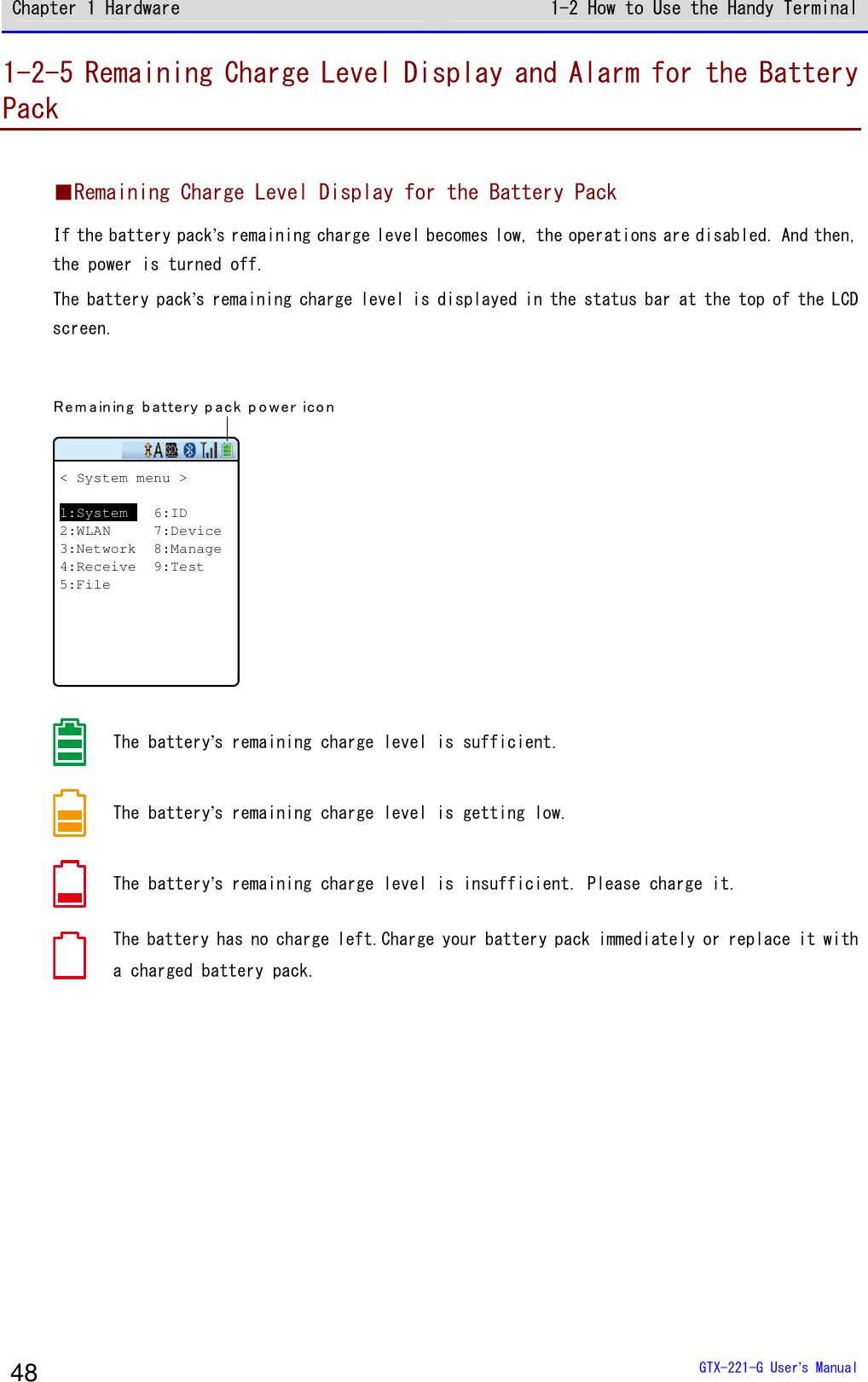
![Chapter 1 Hardware 1-3 Basic Usage Method GTX-221-G User’s Manual 55 1-3-3 Useful Features during Operation ■Forcible Startup on the System Menu In the power OFF state, when the Handy Terminal is started by pressing the【PW】Key while holding down the【SCAN】key, the system menu is forcibly launched even when "Auto execute" is set on the application software. ■Auto-dimming Setting The Handy Terminal has a built-in ambient light sensor which senses the surroundings and automatically controls the dimming of the LCD backlight and the lighting of the key backlights. On the system menu, select [7:Device]-[4:Display]-[2:SetAlsSensor] and make the setting. However, when the backlight is set to remain bright for a certain time after key entry, it will go dim after being lighted up for the set time. ■Buzzer Volume Adjustment You can adjust the buzzer volume, the key click sound, etc. On the system menu, select [7:Device]-[5:Tone/Vibrator] and make the setting. rrrreeeeffff For its detailed setting method, see "4-9-5 Tone/Vibrator: Setting the Volume, LED, and the Vibrator" (P.178).](https://usermanual.wiki/Welcat/GTX221G/User-Guide-1799364-Page-56.png)
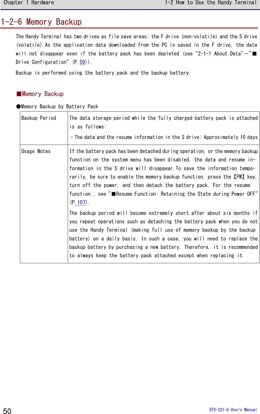
![Chapter 1 Hardware 1-3 Basic Usage Method GTX-221-G User’s Manual 56 ■Resume Function (Retention of the State during Power OFF) If the resume function is enabled, the state when the power was turned OFF is saved, allowing you to resume your work thereafter upon the next startup. You can select the operations on power resumption when selecting [1:System]-[3:Power Management]-[2:Resume]. rrrreeeeffff For its detailed setting method, see "4-3-3 Power Management: Various Settings Related to Power" (P.107). Caution ・If the battery pack is removed during operation, upon the next startup the initial screen will be launched regardless of whether the resume function is enabled or disabled. ・If the backup battery is depleted, the initial screen will be started from the start regardless of the enable/disable state of the resume function. For charging the backup battery, see "1-2-6 Memory Backup" (P.51) ■Auto Wakeup (Power ON after Preset Time) If the auto wakeup function is enabled, the Handy Terminal can be started automatically according to a preset schedule. In the settings of the auto wakeup function, select [1:System]-[3:Power Management]―[2:Auto wake up]. rrrreeeeffff For its detailed setting method, see "4-3-3 Power Management: Various Settings Related to Power"-"Auto Wakeup: Startup at a Predetermined Time" (P.109) ■Auto Power OFF (Automatic Power OFF) If no operation is performed for a certain time, the power will automatically be turned OFF. You can set the time after which the power is turned OFF when selecting <1:System> > <3:Power Management> > <3:Auto power off> on the system menu. rrrreeeeffff For its detailed setting method, see "■Auto Power OFF: Automatic Power OFF" (P.111).](https://usermanual.wiki/Welcat/GTX221G/User-Guide-1799364-Page-57.png)


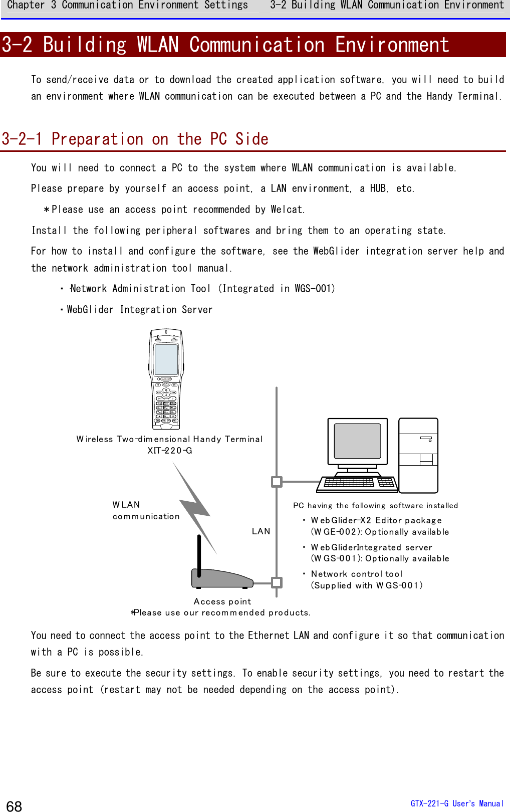
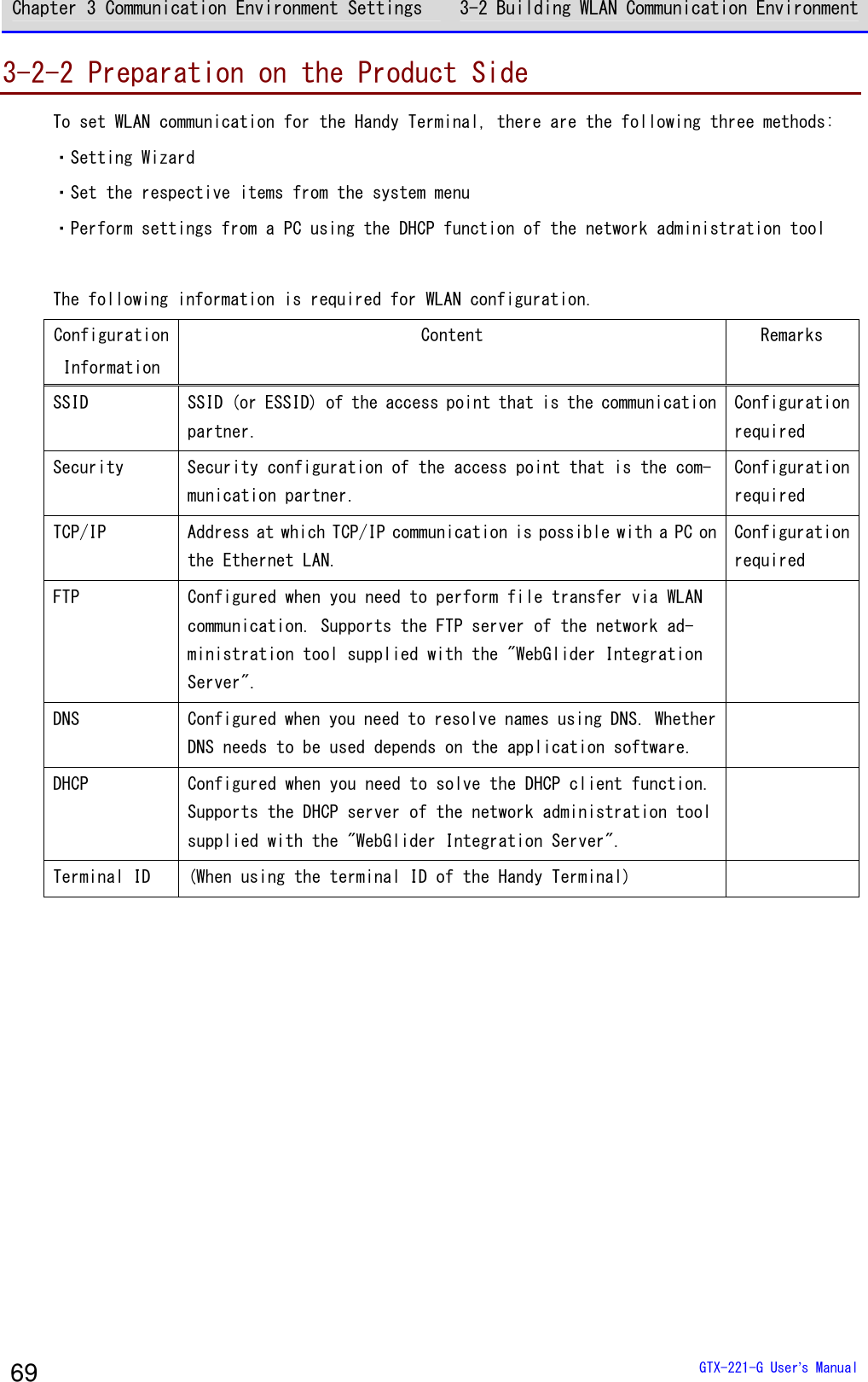
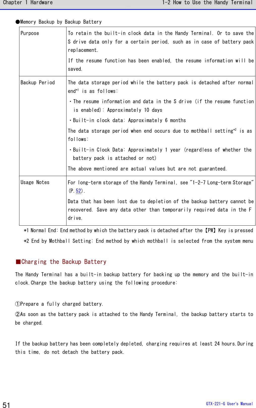
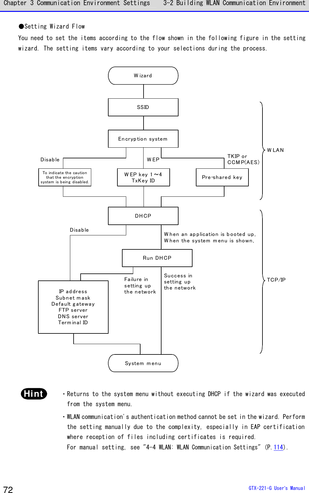
![Chapter 3 Communication Environment Settings 3-2 Building WLAN Communication Environment GTX-221-G User’s Manual 70 Caution If the encryption of WLAN communication has been disabled, a dialog will be displayed to prompt you to enable it upon startup. Encryption systemof WLAN is invalid, Security problemmay occur. Be sureto get setup.Would you like tostart setup now?YES NO Select[Yes]or[No]. To move to "2:WLAN", select[Yes]. Selecting[No]displays the system menu. ■WLAN Communication Settings by Setting Wizard Caution Prior to launching the setting wizard, verify that the Ethernet LAN side to which an access point has been connected is ready for use. At the first startup after purchasing the Handy Terminal, a setting wizard is executed for performing the minimum required settings for WLAN communication with a PC. If it was not set the first time, launch the setting wizard by selecting[8:Manage]-[6:Wizard]. ①The setting wizard start screen is displayed. Select[Yes] to execute the wizard. < Wizard >Start wizard?Communication set-ting can be donewith guidanceYES NO](https://usermanual.wiki/Welcat/GTX221G/User-Guide-1799364-Page-71.png)
![Chapter 3 Communication Environment Settings 3-2 Building WLAN Communication Environment GTX-221-G User’s Manual 71 ②Proceed with the setting according to the screen instructions. Be sure to perform the security configuration. If the Handy Terminal is launched without performing the security configuration, the <WLAN Communication Security Not Configured> prompt screen will be displayed. For configuration items, see the next section, "Setting Wizard Flow". ③Upon completion of configuration, perform Ping test for the access point the first time. Select[9:Test]-[1:WLAN]-[1:Configuration]on the system menu, and execute[2:WLAN/ping] after entering the IP address of the access point. < WLAN/ping >Host=000.000.000.000Time < 000.000 msecNo.00000 1472BytesLnkQ CH:11ASL AP_MAC[000000000000] ④In the same way, perform Ping test for the IP address of the PC.](https://usermanual.wiki/Welcat/GTX221G/User-Guide-1799364-Page-72.png)
![Chapter 3 Communication Environment Settings 3-2 Building WLAN Communication Environment GTX-221-G User’s Manual 73 ■WLAN Communication Settings by the System Menu You can set the required items individually from the system menu. Perform the setting using the following procedure: ①Launch the system menu. ②Set the required items with reference to the following table. ③Perform Ping test and verify the communication state. Item System Menu Reference page SSID Configuration [2:WLAN]-[1:SSID] "3-4-1 SSID: SSID Configuration" (P.114) Security Configuration [2:WLAN]-[4:Security] "3-4-4 Security: WLAN Communica-tion Security Configuration" (P.116) TCP/IP Configuration [3:Network]-[1:TCP/IP] "3-5-1 TCP IP: TCP/IP Configura-tion" (P.131) DHCP Configuration [3:Network]-[2:DHCP] "3-5-2 DHCP: DHCP Configuration" (P.133) FTP Configuration <3:Network> <3:FTP> "3-5-3 FTP: FTP Configuration" (P.136) DNS Configuration [3:Network]-[4:DNS] "3-5-4 DNS: DNS Configuration" (P.140) Terminal ID Configuration <6:Terminal ID> "4-8 Terminal ID: Configure the ID for Terminal Identification" (P.162)](https://usermanual.wiki/Welcat/GTX221G/User-Guide-1799364-Page-74.png)
![Chapter 3 Communication Environment Settings 3-2 Building WLAN Communication Environment GTX-221-G User’s Manual 74 ■WLAN Communication Settings by DHCP You can configure the required items collectively on the PC side using the DHCP client function. When using the DHCP client function, you need "Network Administration Tool", which is separately supplied with "WebGlider Integration Server". Caution Configuring "SSID Configuration" and "Security Configuration" items using the DHCP client function may generate security vulnerability. Avoid using it to the extent possible. To enable the DHCP function, perform the following configurations on the system menu: ①[3:Network]-[2:DHCP]-[Startup type] ②Select[Application boot]. < Startup type >DisabledApplication bootSystem menu bootAuto wake up boot ③Configure the port number of the DHCP server. < DHCP >1:Startup type2:Item not to Update3:Server port[08067]ExecuteF1 rrrreeeeffff See "4-5-2 DHCP: DHCP Settings" (P.133) and "WebGlider Integration Server WGS-001 Manual". Hint This manual has a DHCP mark for items that can be configured by DHCP.](https://usermanual.wiki/Welcat/GTX221G/User-Guide-1799364-Page-75.png)
 from the displayed menu. ③On the network administration tool configuration screen, click the [FTP] tab, and then perform the following configuration: ・Select the [FTP server](FTP サーバー) checkbox. ・[Transmit folder](送信フォルダ) and [Receive folder](受信フォルダ) specify the folders on the FTP server where the application software file is located. ④Select [4:Receive]-[1:WLAN]on the system menu.](https://usermanual.wiki/Welcat/GTX221G/User-Guide-1799364-Page-76.png)
![Chapter 3 Communication Environment Settings 3-2 Building WLAN Communication Environment GTX-221-G User’s Manual 76 < Device type >1:WLAN2:Bluetooth3:IrDA ⑤The list of downloadable files is displayed. Select the files to be downloaded by checking their names. Press the【F1】key to start the download.When the confirmation prompt is displayed, select [Yes] and then press the【ENT】key. Downloading a large file may take long time. < File list >SAMPLE1.OUTSAMPLE2.OUTReceive MenuF1 F2](https://usermanual.wiki/Welcat/GTX221G/User-Guide-1799364-Page-77.png)
-[Program](プログラム)-[Welcat BluePorter-V]-[Welcat BluePorter-V]. ②Right-click the icon of the transfer utility BluePorter-V displayed in the task tray. ③Click[Communication setting](通信設定)from the displayed menu. ④Set[COM Port No. to Use](使用する COM ポート番号)to the desired COM port number. [Receive folder](受信フォルダ)and[Transmit folder](送信フォルダ)specify the folders](https://usermanual.wiki/Welcat/GTX221G/User-Guide-1799364-Page-79.png)
![Chapter 3 Communication Environment Settings 3-3 Building Bluetooth Communication GTX-221-G User’s Manual 79 where the application software file is located. The following figure shows an example where the application software is located in the "C:\Welcat\test_apl" folder. ⑤Press the [OK] button to close the window. After the following screen appears, click [Yes](はい). ⑥Copy the execution file of the application software to the folder set as the transmission folder of BluePorter-V("C:\Welcat\test_apl" in the above example). ⑦Select [4:Receive]-[2:Bluetooth] on the system menu.](https://usermanual.wiki/Welcat/GTX221G/User-Guide-1799364-Page-80.png)
![Chapter 3 Communication Environment Settings 3-3 Building Bluetooth Communication GTX-221-G User’s Manual 80 < Device type >1:WLAN2:Bluetooth3:IrDA ⑧Select [1:Select from list]. < Receiving method >1:Select from list2:wait(PC)3:wait(HT) ⑨The Handy Terminal automatically logs in BluePorter-V, displaying the list of downloadable files. Select the files to be downloaded by checking their names. Pressing the【F1】Key displays the confirmation message box.Move your mouse over [Yes] and then press the【ENT】key to start download. It will take from several seconds to several minutes to complete. However, downloading a large file may take long time. < File list >SAMPLE1.OUTSAMPLE2.OUTReceive MenuF1 F2](https://usermanual.wiki/Welcat/GTX221G/User-Guide-1799364-Page-81.png)
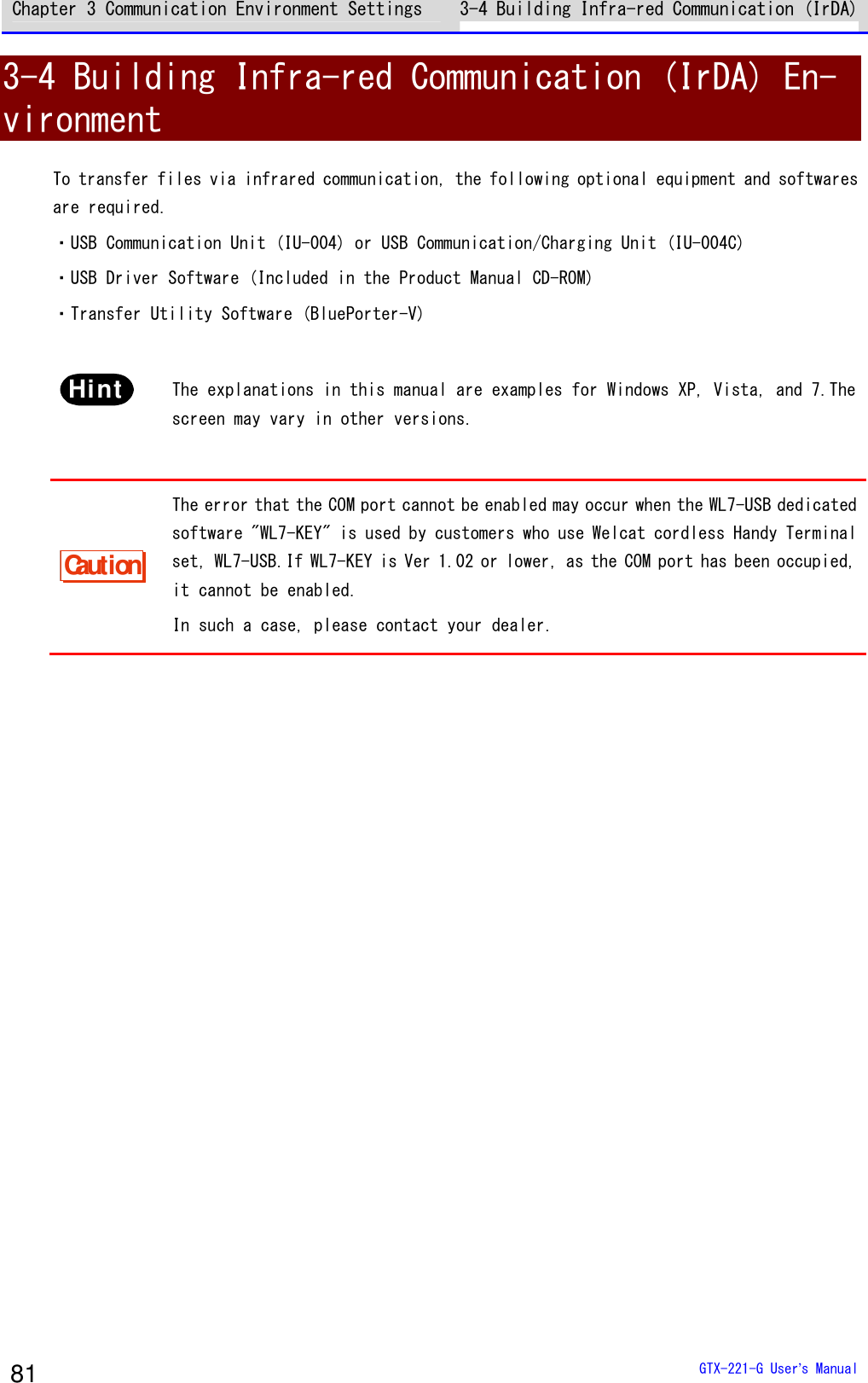
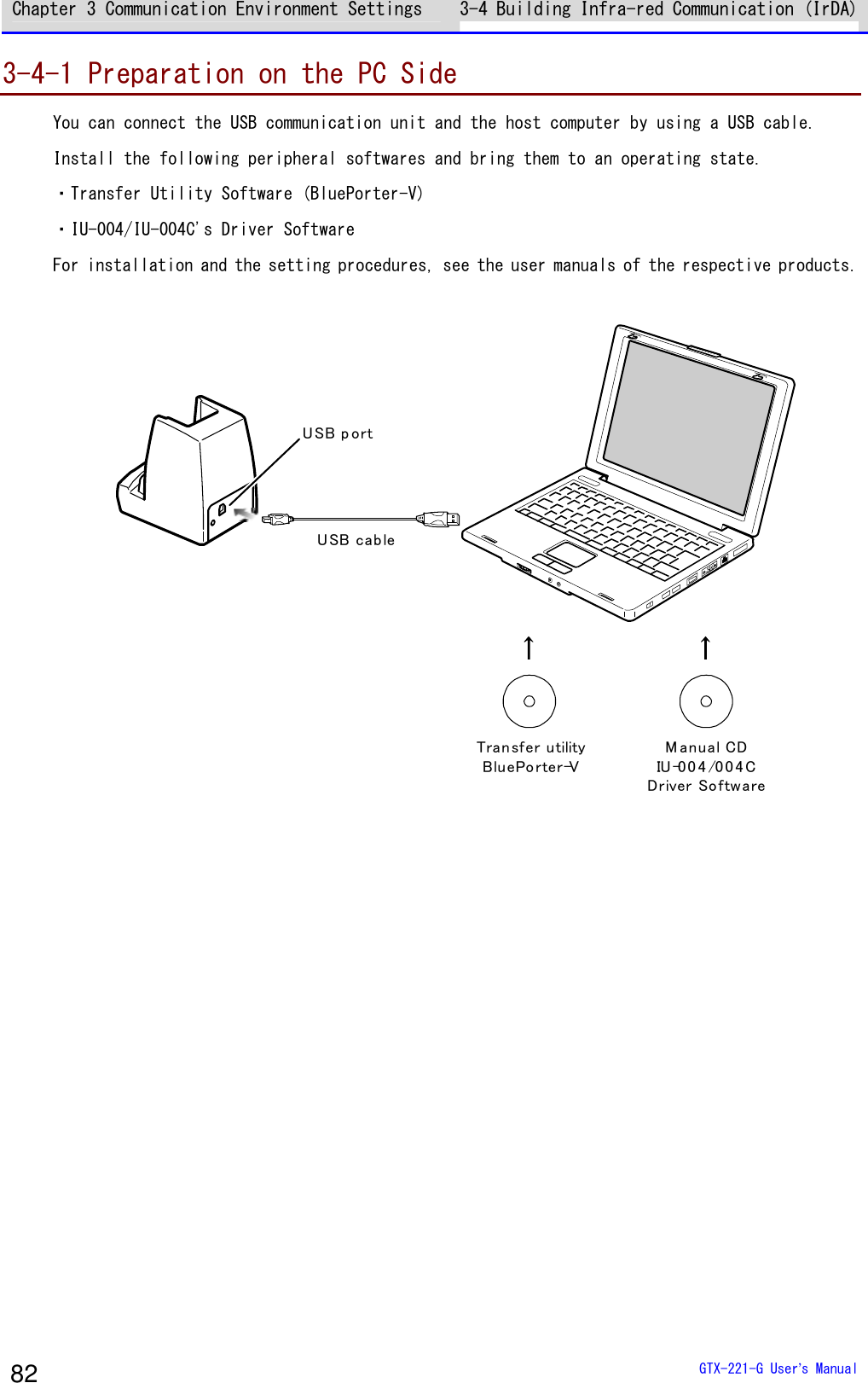
![Chapter 3 Communication Environment Settings 3-4 Building Infra-red Communication (IrDA) GTX-221-G User’s Manual 83 3-4-2 Downloading the Application Software by Infrared Com-munication (IrDA) After the infrared communication environment is ready, you can download your files according to the following procedure. ■Equipment Preparation Prepare the following equipment and software. ・The Product ・Transfer Utility (BluePorter-V) ・USB Communication Unit (IU-004/IU-004C) ■Preparation before Use ①Install the transfer utility BluePorter-V in your PC. ②Install the USB driver of the USB communication unit in the host computer. * For how to install the USB driver, see "3-4 Building Infra-red Communication (IrDA) Environment" (P.81). ●When Launching the Setting Wizard At the first startup after purchasing the Handy Terminal, a setting wizard is executed for performing the minimum required settings for Bluetooth communication with a PC. This wizard is not required in infrared communication mode. Selecting[No]on the wizard screen launches the system menu. To perform Bluetooth communication, start the wizard with reference of "4-10-6 Wizard: Starting the Screen Facilitating Configuration of Communication Settings" (P.197) and make the settings.](https://usermanual.wiki/Welcat/GTX221G/User-Guide-1799364-Page-84.png)
- [Program](プログラム) -[Welcat BluePorter-V]. After it is launched, its icon is displayed in the task tray. Right-click the displayed "BluePorter-V" icon, and then click[Communication setting]on the displayed menu. ■Communication Settings You can set the transmission folder, the reception folder and the COM port to use. ①Right-click the icon displayed in the task tray, and then click the[Communication setting](通信設定)on the displayed menu.](https://usermanual.wiki/Welcat/GTX221G/User-Guide-1799364-Page-85.png)
to the COM port number using the device manager . For how to verify the COM port number, see the user manual of IU-004/IU-004C. [Receive folder](受信フォルダ)and [Transmit folder](送信フォルダ) specify the folders where the application software file is located. The following figure shows an example where the application software is located in the "C:\Welcat\test_apl" folder. ③Press the[Yes]button to close the window. When the following screen appears, click[Yes](はい).](https://usermanual.wiki/Welcat/GTX221G/User-Guide-1799364-Page-86.png)
![Chapter 3 Communication Environment Settings 3-4 Building Infra-red Communication (IrDA) GTX-221-G User’s Manual 86 ■File Download ①Copy the execution file of the application software to the folder set as the transmission folder of BluePorter-V ("C:\Welcat\test_apl" in the above example). ②Next, launch the system menu. On the system menu, select [2:Receive]-[3:IrDA]-[1:Select from list]. < System menu >1:System 6:ID2:WLAN 7:Device3:Network 8:Manage4:Receive 9:Test5:File → < Device type >1:WLAN2:Bluetooth3:IrDA → < Receiving method >1:Select from list2:Wait(HT) ③The Handy Terminal automatically logs in BluePorter-V, displaying the list of downloadable files. Select the files to be downloaded by checking their names. < File list >SAMPLE1.OUTSAMPLE2.OUTExecute MenuF1 F2](https://usermanual.wiki/Welcat/GTX221G/User-Guide-1799364-Page-87.png)
![Chapter 3 Communication Environment Settings 3-4 Building Infra-red Communication (IrDA) GTX-221-G User’s Manual 87 ④Set the Handy Terminal to the USB communication unit. Pressing the【F1】key displays the[Would you like to receive it?] screen.Select[Yes]and then press the【ENT】Key to start download. It will take from several seconds to several minutes to complete. However, downloading a large file may take long time.](https://usermanual.wiki/Welcat/GTX221G/User-Guide-1799364-Page-88.png)
![Chapter 3 Communication Environment Settings 3-5 Executing the Application Software GTX-221-G User’s Manual 88 3-5 Executing the Application Software Once the downloaded application software (file extension=OUT) is received into the Handy Terminal, its installation is complete and it is ready for execution. ■Selecting from the File List to Execute If multiple application softwares have been installed, you can select the files from the file list and execute them. ①Select[5:File]- <Select drive> -[1:Application]on the system menu. < System menu >1:System 6:ID2:WLAN 7:Device3:Network 8:Manage4:Receive 9:Test5:File → < Drive type >1:FDrive2:SDrive3:RDrive(microSD)→< File type >ApplicationDataAudioGraphicAll type ②Select the application software and then press the【F1】key < FDrive >WGX2BRWS.OUTMenu SDriveF1 F2](https://usermanual.wiki/Welcat/GTX221G/User-Guide-1799364-Page-89.png)
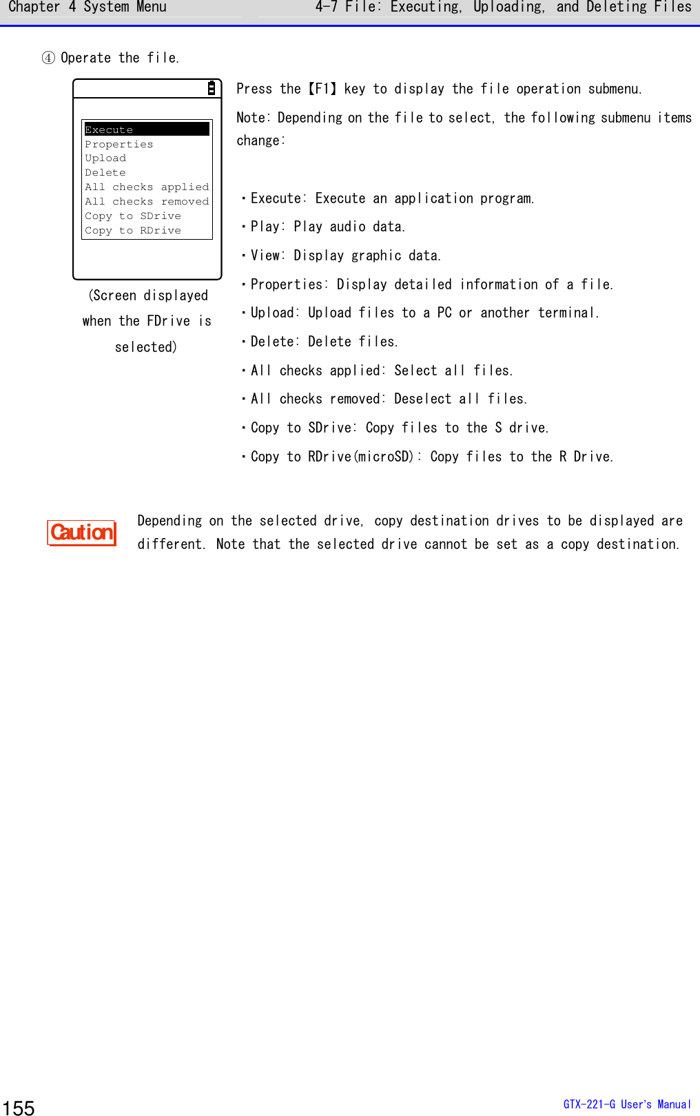
![Chapter 3 Communication Environment Settings 3-5 Executing the Application Software GTX-221-G User’s Manual 89 ③From the popup menu, select [Execute], and then press the【ENT】key. The < Execute> screen is displayed and the confirmation query on registration to the automatic execution program is displayed. To perform automatic execution select[Yes], otherwise select[No], and then press the【ENT】key. ExecutePropertiesUploadDeleteAll checks appliedAll checks removedCopy to SDriveCopy to RDrive → Would you like toregister with“Auto execute”?YES NO The application software is launched. For how to use the respective application softwares, see the operation instruction manual and other manuals prepared by the application software developer or the system administrator. The application software is basically terminated by pressing the【PW】key. However, this may not apply to all application softwares.](https://usermanual.wiki/Welcat/GTX221G/User-Guide-1799364-Page-90.png)
![Chapter 3 Communication Environment Settings 3-5 Executing the Application Software GTX-221-G User’s Manual 90 ■Automatic Execution upon Startup You can automatically execute the application software without launching the system menu during startup of the Handy Terminal. ①Select[1:System]-[1:Auto execute] in the system menu. < System menu >1:System 6:ID2:WLAN 7:Device3:Network 8:Manage4:Receive 9:Test5:File → < System setting >1:Auto execute2:Clock3:Power management4:Password ②Select the file name to execute from the list of installed application softwares, and then press the【ENT】Key to return to the <System setting> screen. This completes registration of the automatic execution file. When the power is turned on the next time, the registered application software is launched. The system menu is launched if it has been set for automatic execution. < Auto execute >System menuWGX2BRWS.OUTPropertyF1](https://usermanual.wiki/Welcat/GTX221G/User-Guide-1799364-Page-91.png)

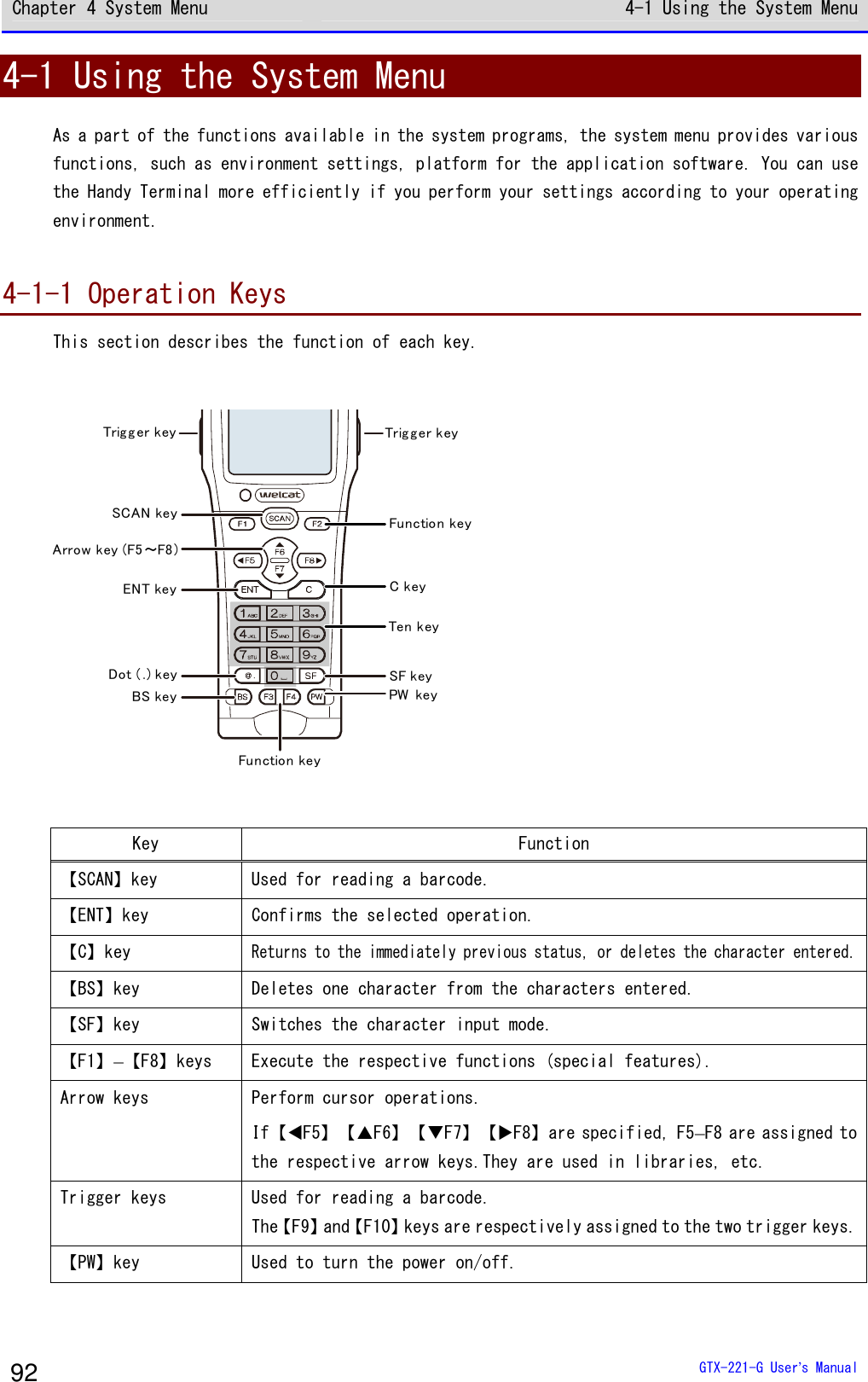
![Chapter 4 System Menu 4-1 Using the System Menu GTX-221-G User’s Manual 94 4-1-2 Launching the System Menu By default settings, the system menu is launched when you power on the Handy Terminal. If the application software has been selected in the automatic execution program (P.103), launch the system menu using the following operations: ①In the power OFF state, press the【PW】key for about one second while holding down the【SCAN】key. The system menu is launched when the power is turned on. ②After the opening screen is displayed, the system menu appears. < System menu >1:System 6:ID2:WLAN 7:Device3:Network 8:Manage4:Receive 9:Test5:File 4-1-3 When Launching the System Menu for the First Time When you start the Handy Terminal for the first time after purchasing it, the setting wizard is executed to allow you to perform the minimum required settings for WLAN communication between the server and the Handy Terminal. < Wizard >Start wizard?Communication set-ting can be donewith guidanceYES NO • Select [Yes] to execute the wizard where you perform WLAN communication settings. • Selecting [No] launches the system menu.](https://usermanual.wiki/Welcat/GTX221G/User-Guide-1799364-Page-95.png)
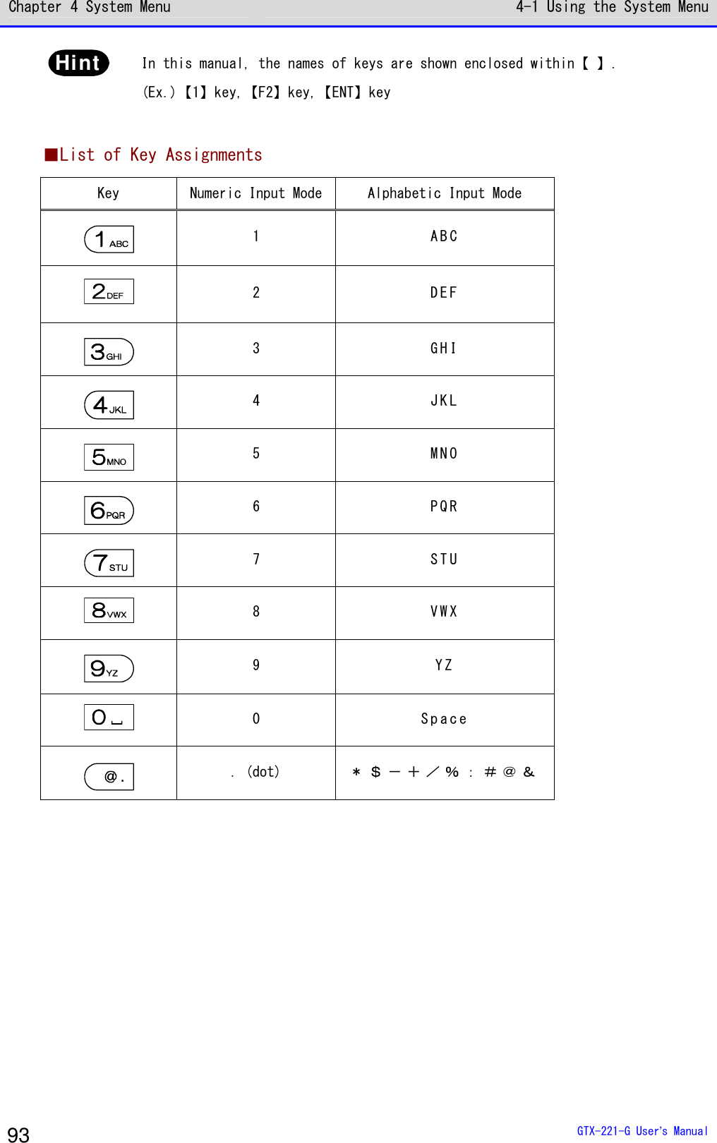
![Chapter 4 System Menu 4-1 Using the System Menu GTX-221-G User’s Manual 95 Select [No] to skip the setting wizard, or execute the setting wizard till you complete all the settings to avoid launching the setting wizard at the next startup. rrrreeeeffff For how to use the setting wizard, see "■WLAN Communication Settings by Setting Wizard" (P.70). 4-1-4 Using the System Menu This section describes the basic operations of the system menu. ■Selecting Setting Items < System setting >1:Auto execute2:Clock3:Power management4:PasswordAn item beingselected ishighlighted.Can directly select an item you want simplyby pressing the number of that item.Can move fromone item to otherwith the directionalkey (⊳,,,). ●Select an Item The selected item is highlighted. Press the key from【0】–【9】that corresponds to the respective item, or use the arrow keys (【】,【】) to move the highlighted display. ●Confirm the Item Selection Press the【ENT】key to confirm the item selection. The operations after the confirmation vary depending on the items. • Execute the selected function • Select one of the two options:[Yes] or[No] (button) • Display its submenu ●Cancel Your Selection Press the【C】key to return to the immediately previous operation.](https://usermanual.wiki/Welcat/GTX221G/User-Guide-1799364-Page-96.png)
![Chapter 4 System Menu 4-1 Using the System Menu GTX-221-G User’s Manual 98 ■Other Operations Returning to the Immediately Previous Status 【C】key Checkbox < Security >Pairing EnablePIN code[ ] Select the item, and press the【ENT】key to toggle between Selected and Cleared. A check mark is attached to the selected box. Checkboxes are used for selecting multiple items at a time. Radio Button < Click Sound >NoneBeepBeep + AudioAudio Select the item, and press the【ENT】key to change the item selected. The item with a filled circle indicates that it is currently enabled. The radio button is used when only one item is to be selected from multiple items. Message Box The remote hasbeen alreadyregistered.Would you like tooverwrite it?YES NO When two buttons, such as[Yes]and[No], are displayed, press either the【1】or the【2】key, or use the arrow keys (【】,【▼】,【⊳】,or【】) to select your desired button (highlighted), and then press the【ENT】key to confirm. Press the【C】key to select the button on the right.](https://usermanual.wiki/Welcat/GTX221G/User-Guide-1799364-Page-99.png)
![Chapter 4 System Menu 4-1 Using the System Menu GTX-221-G User’s Manual 99 Calling the Submenu < Prooerty >1:Device nameXIT-2202:BD Address[00:03:7A:0B:0A:AB]3:SecuritySave SearchF1 F2 While [F1] or [F2] is displayed at the bottom of the screen, press the corresponding key to display its submenu or to execute its function (special feature). Slider < Volume >F6(Up)Level : 4F7(Down) Use the【▲】【▼】keys to move the slider for performing the setting. Indicator Change during Op-eration You can change the indicator (buzzer/vibrator/LED) that works during operation according your individual settings. For its change method, see "4-9-5 Tone/Vibrator: Setting the Volume, LED, and the Vibrator" (P.178). By changing this setting, you can create your individual indicator in a simple way. In addition, there are operations that are not applicable for some indicators.](https://usermanual.wiki/Welcat/GTX221G/User-Guide-1799364-Page-100.png)
![Chapter 4 System Menu 4-3 System: Settings to Simplify Your Operations GTX-221-G User’s Manual 103 4-3 System: Settings to Simplify Your Operations You can set various functions that make your operations of the Handy Terminal more comfortable. You can automatically register the settings for the respective systems (except the password setting) by using the DHCP function. rrrreeeeffff "4-5-2 DHCP: DHCP Settings" (P.133) [System Menu]→[1:System] < System setting >1:Auto execute2:Clock3:Power management4:Password Select the item to be set. ・Auto execute: Automatic execution of the application software (P.103) ・Clock: Clock Verification (P.104) ・Power Management (P.107) ・Password: Setting/Clearing Password (P.107)](https://usermanual.wiki/Welcat/GTX221G/User-Guide-1799364-Page-104.png)
![Chapter 4 System Menu 4-3 System: Settings to Simplify Your Operations GTX-221-G User’s Manual 104 4-3-1 Auto Execute: Automatic Execution of the Application Software DHCP You need to register the application software that you want launched automatically upon power ON. The system menu is launched by the factory settings. [System Menu]→[1:System]→[1:Auto execute] Select the application software you want launched automatically upon power ON. < Auto execute >System menuSAMPLE1.OUTSAMPLE2.OUTPropertyF1 After the list of currently installed programs is displayed, select your desired application software. Press the【ENT】key to return to the <System setting> screen.This completes registration of the automatic execution file. When the power is turned on the next time, the registered application software will be launched. < File Property >NameSAMPLE1.OUTType[Application]Library[1.00]Size[00000000]BytesModified2012/01/0100:00:00 Press the【F1】key to display the information related to the selected application software. Press the【C】key to return to the <Auto execute> screen.](https://usermanual.wiki/Welcat/GTX221G/User-Guide-1799364-Page-105.png)
![Chapter 4 System Menu 4-3 System: Settings to Simplify Your Operations GTX-221-G User’s Manual 105 4-3-2 Clock: Time Settings DHCP You can verify the current time and perform time settings. In additional to making the settings manually, you can also receive the PC time data using WLAN communication. ■Current Time [System Menu]→[1:System]→[2:Clock] Select whether to set the time manually or via the server. < Time >2012/01/01(Sun)00/00/001:Manual setting2:Server setting The current time is displayed. Select the item to be set. ・Manual setting: Sets the time manually· ・Server setting: Receives the time automatically from the server ■Manual setting: Sets the Time Manually [System Menu]→[1:System]→[2:Clock]→[1:Manual setting] Set the time. < Manual setting >2012/01/01 00:00:00 Use the arrow keys to move the cursor over the year, the month or the day to be set, and then enter the time. Press the【ENT】key to confirm the time and return to the <Current time> screen. Press the【C】key to cancel the setting and return to the <Current time> screen.](https://usermanual.wiki/Welcat/GTX221G/User-Guide-1799364-Page-106.png)
![Chapter 4 System Menu 4-3 System: Settings to Simplify Your Operations GTX-221-G User’s Manual 106 ■Server setting: Receives the time automatically from the server Receives the time data from the DHCP server, a network administration tool (see "7-2 DHCP Server Mode" of "Network Administration Tool User Manual"). [System Menu]→[1:System]→[2:Clock]→[2:Server setting]→ [1:WLAN]/[2:Bluetooth]/[3:IrDA] CompletedOK Receive the time data automatically. Press the【ENT】key to return to the <Current time> screen. Failed to getthe current time.(65540)Retry?RETRY CANCEL When reception fails, the screen on the left will be displayed. ・Retry: Receives the time data from the server again. ・Cancel: Cancels the setting and return to the <Current time> screen. If the failure persists, contact your system administrator. Hint To set the current time, get the time data from the server by using the DHCP function. When using the DHCP function to set the current time, confirm the following in advance: ・The WLAN communication (such as SSID and security) between the Handy Terminal and the access point has been configured correctly. ・The access point and the PC have been powered up. ・The access point and the PC have been configured and connected correctly. ・The access point is operating normally. ・The DHCP server of the network administration tool has been started.](https://usermanual.wiki/Welcat/GTX221G/User-Guide-1799364-Page-107.png)
![Chapter 4 System Menu 4-3 System: Settings to Simplify Your Operations GTX-221-G User’s Manual 107 4-3-3 Power Management: Various Settings Related to Power You can perform various settings related to Power ON/OFF, such as auto power off. [System Menu]→[1:System]→[3:Power Management] < Power management >1:Resume2:Auto wake up3:Auto power off Select the item to be set. ·Resume: Retention of the state during power off ·Auto wake up: Started at the predefined time ·Auto power off: Automatically power off ■Resume Function: Retaining the State during Power OFF If the resume function is enabled, the state when the power was turned off is saved, allowing you to resume your work thereafter upon the next startup. The operations after pressing the【PW】key to turn on the power are as follows, depending on whether the resume function is enabled: • Resume function enabled: Resumes from the process executed immediately before power off. • Resume function disabled: Always executed from the beginning process. Hint To cancel the resume function and launch the system menu, press the【PW】key while holding down the SCAN key.](https://usermanual.wiki/Welcat/GTX221G/User-Guide-1799364-Page-108.png)
![Chapter 4 System Menu 4-3 System: Settings to Simplify Your Operations GTX-221-G User’s Manual 108 Caution ・If the battery pack is detached during operation, resume will fail. The process will then be executed from the beginning, regardless of whether the resume function is enabled or disabled. The following screen will be displayed upon the next power on. Backup failure.Format S drive.Start up thisterminal usually.Hit ENT key. ・When the backup battery is depleted, the above screen will be displayed, and the process will be executed from the very beginning. For charging the backup battery, see "1-2-5 Remaining Charge Level Display and Alarm for the Battery Pack"-"■Charging the Backup Battery" (P.49). ・The resume is disabled on the system menu even when the resume setting is enabled. The resume is enabled only while the application software is operating. [System Menu]→[1:System]→[3:Power Management]→[1:Resume] Enable the resume function. < Resume >Enabled Press the【ENT】key to select[Enabled]. rrrreeeeffff You can also enable the resume function from the DHCP server, a network ad-ministration tool (see "7-2 DHCP Server Mode" of "Network Administration Tool User Manual").](https://usermanual.wiki/Welcat/GTX221G/User-Guide-1799364-Page-109.png)
![Chapter 4 System Menu 4-3 System: Settings to Simplify Your Operations GTX-221-G User’s Manual 109 ■Auto wakeup: Started at the Predefined Time The auto wake up function can automatically start the Handy Terminal according to a predefined schedule. Caution The auto wake up function can be enabled only if the power is turned off using the【PW】Key. The Handy Terminal cannot be started by Auto wake up immediately after battery replacement or after forcible termination due to low battery. ●Schedule Confirmation [System Menu]→[1:System]→[3:Power Management]→[2:Auto wake up] The currently set start schedule is displayed. Select the item to be set. < Present schedule >at 07:30on Mondayevery week.1:Set2:Clear Select from the following items: ・Set: Sets the schedule ・Clear: Clears the schedule](https://usermanual.wiki/Welcat/GTX221G/User-Guide-1799364-Page-110.png)
![Chapter 4 System Menu 4-3 System: Settings to Simplify Your Operations GTX-221-G User’s Manual 110 ●Set: Sets the Schedule [System Menu]→[1:System]→[3:Power Management]→[2:Auto wake up] →[1:Set] Set the auto wakeup schedule. < Schedule setting >Cycle [every day ]every weekevery month Select the occurrence interval of the schedule. Select Daily (time specification), Weekly (weekday and time specification), Monthly (date and time specification). Date is set using "01"–"31", and time is set using the 24-hour format. The menu returns to schedule confirmation upon completion of the setting. < Schedule setting >Cycle [every month]Date [01]Time [01:00] Enter the hours and minutes (00:00–23:59) in the 24-hour format. This completes the settings. Press the【ENT】Key to return to the<Current schedule> screen and complete the setting. ●Clear: Clear the Schedule [System Menu]→[1:System]→[3:Power Management]→[2:Auto wake up] →[2:Clear] Clear the auto wakeup schedule that has been set. < Schedule clear >Would you like toclear schedule?YES NO Select[Yes]in the confirmation dialog. The set schedule is deleted. Select[No]to cancel the clearing. rrrreeeeffff You can also enable the auto wakeup function from the DHCP server, a network administration tool (see "7-2 DHCP Server Mode" of "Network Administration Tool User Manual").](https://usermanual.wiki/Welcat/GTX221G/User-Guide-1799364-Page-111.png)
![Chapter 4 System Menu 4-3 System: Settings to Simplify Your Operations GTX-221-G User’s Manual 111 ■Auto Power OFF: Automatic Power OFF The auto power off function performs power off automatically after a time period of no operation. [System Menu]→[1:System]→[3:Power Management]→[3:Auto power off] Set the time duration after which power off is to be performed automatically. < Auto power off >[0600] SecGuidanceF1 The allowed time range is 0060 – 3600 seconds. In addition, power off can be disabled by setting it to 0000 second. Press the【ENT】key to complete the setting. Press the【F1】key to display the guidelines related to the setting values. rrrreeeeffff You can also enable the auto power off function from the DHCP server, a network administration tool (see "7-2 DHCP Server Mode" of "Network Administration Tool User Manual").](https://usermanual.wiki/Welcat/GTX221G/User-Guide-1799364-Page-112.png)
![Chapter 4 System Menu 4-3 System: Settings to Simplify Your Operations GTX-221-G User’s Manual 112 4-3-4 Password: Setting / Clearing Password You can set a password to prevent the system menu from being inadvertently started. If a password has been set, no person other than the administrator can confirm and/or modify the settings without entering the password. Password?*** If a password has been set, password check will be performed during system menu launch. The system menu will not be launched unless the correct password is entered. Caution Write down your password and keep it somewhere safe in order not to forget it. Please contact your dealer if you are unable to recall the password. [System Menu]→[1:System]→[4:Password] You can set or clear the password. < Password >1:Set2:Clear Select from the following items: ・Set ・Clear](https://usermanual.wiki/Welcat/GTX221G/User-Guide-1799364-Page-113.png)
![Chapter 4 System Menu 4-3 System: Settings to Simplify Your Operations GTX-221-G User’s Manual 113 ■Set: Setting the Password [System Menu]→[1:System]→[4:Password]→[1:Set] ① Enter a new password. < Password setting >New passwordNew password again The password is case sensitive and consists of 4–30 alphanumeric characters. Enter a new password, and then press the【ENT】key. ② Enter the password once again for confirmation. < Password setting >New passwordabcdNew password again Press the【ENT】key after entering the password. ■Clear: Clearing the Password [System Menu]→[1:System]→[4:Password]→[2:Clear] Clear the password. < Password clear >Would you like toclear a password?YES NO Select[Yes]to clear the password; the set password will be erased. Select[No]to cancel the clearing.](https://usermanual.wiki/Welcat/GTX221G/User-Guide-1799364-Page-114.png)
![Chapter 4 System Menu 4-4 WLAN: WLAN Communication Settings GTX-221-G User’s Manual 114 4-4 WLAN: WLAN Communication Settings You can perform settings related to WLAN. [System Menu]→[2:WLAN] You can select the setting item for WLAN communication. < WLAN >1:SSID2:Roaming level3:Doze mode4:Security5:Advanced6:MAC address Select the item to be set. ・SSID: Setting SSID (P.114) ・Roaming level: Setting the Roaming Level (P.115) ・Doze mode: Setting the Timeout Time (P.115) ・Security: WLAN Communication Security Settings (P.116) ・Advanced: Advanced Settings Related to WLAN Communication (P.127) ・MAC address: Displaying the MAC Address (P.129) 4-4-1 SSID: Setting SSID You can set SSID for identifying the access point of WLAN communication. Caution Although SSID can be set automatically by using the DHCP function, security issues may occur. Avoid configuration by DHCP. [System Menu]→[2:WLAN]→[1:SSID] < SSID >101 Enter SSID. SSID is specified with up to 32 alphanumeric characters.It is case sensitive.](https://usermanual.wiki/Welcat/GTX221G/User-Guide-1799364-Page-115.png)
![Chapter 4 System Menu 4-4 WLAN: WLAN Communication Settings GTX-221-G User’s Manual 115 4-4-2 Roaming level: Setting the Roaming Level DHCP The roaming function automatically switches to an access point with a stronger signal when the Handy Terminal is moved around. The value for deciding the switching is called roaming level. Roaming is performed only among access points having the same SSID. [System Menu]→[2:WLAN]→[2:Roaming level] < Roaming level >SlowNormalFast Select the speed for deciding the switch. Slow The switch is slow Normal Fast The switch is fast 4-4-3 Doze mode: Setting the Timeout Time DHCP This time is the duration after which WLAN is switched to the doze mode upon completion of transmission. The shorter this time, the lower the consumption of the battery pack. However, the WLAN response will be degraded accordingly. It can be configured automatically if the DHCP function is enabled. [System Menu]→[2:WLAN]→[3:Doze mode] < Doze mode >Quick1 secondNone Select the time duration after which timeout occurs.](https://usermanual.wiki/Welcat/GTX221G/User-Guide-1799364-Page-116.png)
![Chapter 4 System Menu 4-4 WLAN: WLAN Communication Settings GTX-221-G User’s Manual 116 4-4-4 Security: WLAN Communication Security Settings DHCP You can perform settings related to WLAN communication security. [System Menu]→[2:WLAN]→[4:Security] < Security >1:Encryption2:Authentication3:Attention Select the item to be set. ・Encryption: Sets the encryption method and the key ・Authentication: Selects the authentication method ・Attention: Notification when security is not configured ■Encryption You can select the encryption method and set the key used for encryption. [System Menu]→[2:WLAN]→[4:Security]→[1:Encryption] < Encryption >1:Method2:WEP3:PSK(TKIP/CCMP) Select the item to be set. ・Method: Selects the encryption method ・WEP: Sets the WEP key ・PSK(TKIP/CCMP): Sets the encryption key](https://usermanual.wiki/Welcat/GTX221G/User-Guide-1799364-Page-117.png)
![Chapter 4 System Menu 4-4 WLAN: WLAN Communication Settings GTX-221-G User’s Manual 117 ●Method You can select the encryption method. [System Menu]→[2:WLAN]→[4:Security]→[1:Encryption]→[1:Method] < Method >DisabledWEP(40 bit)WEP(128bit)TKIPCCMP Select the encryption method. ・Disabled ・WEP(40-bit) ・WEP(128-bit) ・TKIP ・CCMP(AES) ●WEP [System Menu]→[2:WLAN]→[4:Security]→[1:Encryption]→[2:WEP] < WEP >1:TxKeyIDKEY-1KEY-2KEY-3KEY-42:Key modification Select the item.](https://usermanual.wiki/Welcat/GTX221G/User-Guide-1799364-Page-118.png)
![Chapter 4 System Menu 4-4 WLAN: WLAN Communication Settings GTX-221-G User’s Manual 118 ・TxKeyID From the KEY1–KEY4 set at the next[Key modification], select the ID used for communi-cation.This item is enabled while the WEP setting is other than "Disabled". Caution Communication cannot be performed unless the WEP key value of TxKey_ID set here matches with the WEP key value of the access point and the WEP key value of TransmitKEY set at the access point matches with the WEP key value on the Handy Terminal side. For example, if TxKey_ID of the Handy Terminal is "2", the WEP key2 value of the Handy Terminal and the WEP key2 value of the access point must be consistent. Also, if TransmitKEY of the access point is "3", the WEP key3 value of the access point and the WEP key3 value of the Handy Terminal must match each other. ・Key modification You can set the value of the respective WEP keys (1, 2, 3, 4). The value can contain HEX characters ("0"–"9", "A"–"F") and ASCII characters.Press the【F1】Key to switch the input. You can also make the setting through barcode reading by using the trigger keys. HEX Characters (Default) <Key-1 modification>00000000000000000000000000ASCIIF1 The length is fixed at 10 characters when 40-bit is selected, and at 26 characters when 128-bit is selected. The actual entry is always 26 characters, and when 40-bit is selected, only the first 10 of these 26 characters are accepted. Press the【F1】key to move to the ASCII character entry screen.](https://usermanual.wiki/Welcat/GTX221G/User-Guide-1799364-Page-119.png)
![Chapter 4 System Menu 4-4 WLAN: WLAN Communication Settings GTX-221-G User’s Manual 119 ASCII Characters <Key-1 modification>HEXF1 The length is fixed at 5 characters when 40-bit is selected, and at 13 characters when 128-bit is selected. The actual entry is always 13 characters, and when 40-bit is selected, only the first 5 of the 13 characters are accepted. In addition, blank is recognized as space (0x20). Caution The settings for the respective WEP keys can be overwritten but not edited. From the security perspective, it is always displayed as "00000..." when moving to the KEY modification screen. ●PSK(TKIP/CCMP) [System Menu]→[2:WLAN]→[4:Security]→[1:Encryption] →[3:PSK(TKIP/CCMP)] < PSK(TKIP/CCMP) > When PSK (TKIP/CCMP) is selected in the encryption method, enter the encryption key (key). Perform the same setting as for the access point. You can enter 8–63 characters when setting using ASCII charac-ters.You can enter 64 characters when setting using HEX numbers. To use PSK (TKIP/CCMP), set the authentication method (P.121) to "Open".](https://usermanual.wiki/Welcat/GTX221G/User-Guide-1799364-Page-120.png)
![Chapter 4 System Menu 4-4 WLAN: WLAN Communication Settings GTX-221-G User’s Manual 121 ■Authentication Select the authentication method. [System Menu]→[2:WLAN]→[4:Security]→[2:Authentication] Select the item to be set. < Authentication >1:Method2:EAP modification](https://usermanual.wiki/Welcat/GTX221G/User-Guide-1799364-Page-122.png)
![Chapter 4 System Menu 4-4 WLAN: WLAN Communication Settings GTX-221-G User’s Manual 122 ●Method [System Menu]→[2:WLAN]→[4:Security]→[2:Authentication]-[1:Method] < Authentication >OpenSharedEAP ・Open Set "Open Authentication" method. When the authentication request frame is received from the Handy Terminal, the access point returns with an authentication response frame and enables the data communication. While WEP is enabled, if the two WEP keys do not match, com-munication will not be performed even when authentication has taken place. ・Shared Set "Shared Key Authentication" method. When authentication request is received from the Handy Terminal, the access point sends unencrypted text (challenge text) for identity confirmation. The Handy Terminal then encrypts the challenge text and returns the encrypted text to the access point. The access point decrypts the encrypted text using its WEP key. If the access point confirms that the decrypted text matches the original challenge text, then it authenticates the Handy Terminal. ・EAP Sets the "EAP" (IEEE802.1X) authentication method.When this authentication method is used, you will also need to configure a number of settings including certificate, private key and user information, which will be discussed later. There are also limitations on environment that can be used (such as certificate authority and authentication (RADIUS) server). Therefore, if you want to use the "EAP" authentication method, please contact your dealer.](https://usermanual.wiki/Welcat/GTX221G/User-Guide-1799364-Page-123.png)
![Chapter 4 System Menu 4-4 WLAN: WLAN Communication Settings GTX-221-G User’s Manual 123 ●EAP modification [System Menu]→[2:WLAN]→[4:Security]→[2:Authentication]-[1:EAP modification] Perform the various configurations required when using EAP (IEEE802.1X) authentication. After these settings are configured, perform " ■ WLAN/ping test" (P.202) and verify that communication using EAP authentication is possible. < EAP modification >1:EAP mode2:Certificate3:Private key4:User Info5:Advanced Select the item to be set. ①Select[EAP mode]. < EAP mode >EAP-TLSEAP-PEAP-MSCHAPv2 ・EAP-TLS This authentication method requires a server certificate for server authentication, and a client certificate for client certification. The required settings are as follows: ・CA root certificate ・Client certificate ・Private key ・User name ・EAP-PEAP-MSCHAPv2 This authentication method requires a server certificate for server authentication, and a user name and a password for client authentication. The required settings are as follows: ・CA root certificate ・User name ・Password](https://usermanual.wiki/Welcat/GTX221G/User-Guide-1799364-Page-124.png)
![Chapter 4 System Menu 4-4 WLAN: WLAN Communication Settings GTX-221-G User’s Manual 124 ②Select[Certificate]. You need to set the certificate files.The certificate files are received via WLAN (P.146) or Bluetooth (P.146).They can also be received via IrDA or clone. < Certificate >1:CA root2:ClientClear entryF1 ・CA root (file) This is the CA root certificate of the publisher of the server certificate required for server authentication. It does not support certificate hierarchization (chain). Press the【F1】key to clear the setting value. ・Client certificate (file) This is a client certificate required for client authentication. Press the【F1】key to clear the setting value. <Reference to file>ROOTCERT.CERCLIENTCERT.CERPRIVATE.KEYPropertyF1 Select from the received files. (Pressing the【F1】Key allows you to view the file information)](https://usermanual.wiki/Welcat/GTX221G/User-Guide-1799364-Page-125.png)
![Chapter 4 System Menu 4-4 WLAN: WLAN Communication Settings GTX-221-G User’s Manual 125 ③Select[Private key]. The private key (file) is received via WLAN (P.146) or Bluetooth (P.146). < Private key >1:File2:Password*******************************Clear entryF1 ・File This is the private key that is paired with the client public key contained in the client certificate. This private key is important for security.Manage the private key file by encrypting it so that it will not be leaked to third parties. Press the【F1】key to clear the setting value. ・Password Enter a password that is case sensitive and consists of up to 31 alphanumeric characters. As a security measure, the password characters entered will be displayed as asterisks (*). Press the【F1】key to clear the setting value. <Reference to file>ROOTCERT.CERCLIENTCERT.CERPRIVATE.KEYPropertyF1 Select from the received files. (Press the【F1】Key to view the file information) ④Select[User Info]. < User Info >1:User Name2:Password******************************* ・User Name The user name used for authentication. Enter a user name that is case sensitive and consists of up to 62 alphanumeric characters. ・Password The password used for authentication. Enter a password that is case sensitive and consists of up to 31 alphanumeric characters. As a security measure, the password characters entered will be displayed as asterisks (*).](https://usermanual.wiki/Welcat/GTX221G/User-Guide-1799364-Page-126.png)
![Chapter 4 System Menu 4-4 WLAN: WLAN Communication Settings GTX-221-G User’s Manual 126 ⑤Select[Advanced]. *This setting usually does not change. < EAP Advanced >1:AuthenticationTime[060]sec ・Authentication timeout during startup During WLAN startup, authentication will not be terminated till after lapse of the number of seconds set here. Allowed setting value: 15–120 seconds ■Attention If the Handy Terminal is launched without performing the WLAN security configuration, the <WLAN Communication Security Not Configured> prompt screen will be displayed. This display can be shown/hidden. If this setting is disabled, even if the WLAN communication security is not configured, the notification screen will not be displayed during startup. Caution From the security perspective, disabling this setting is not recommended. Be sure to configure security when performing WLAN communication. [System Menu]→[2:WLAN]→[4:Security]→[3:Attention] < Attention >DisplayNot Display Select Display/Don’t Display.](https://usermanual.wiki/Welcat/GTX221G/User-Guide-1799364-Page-127.png)
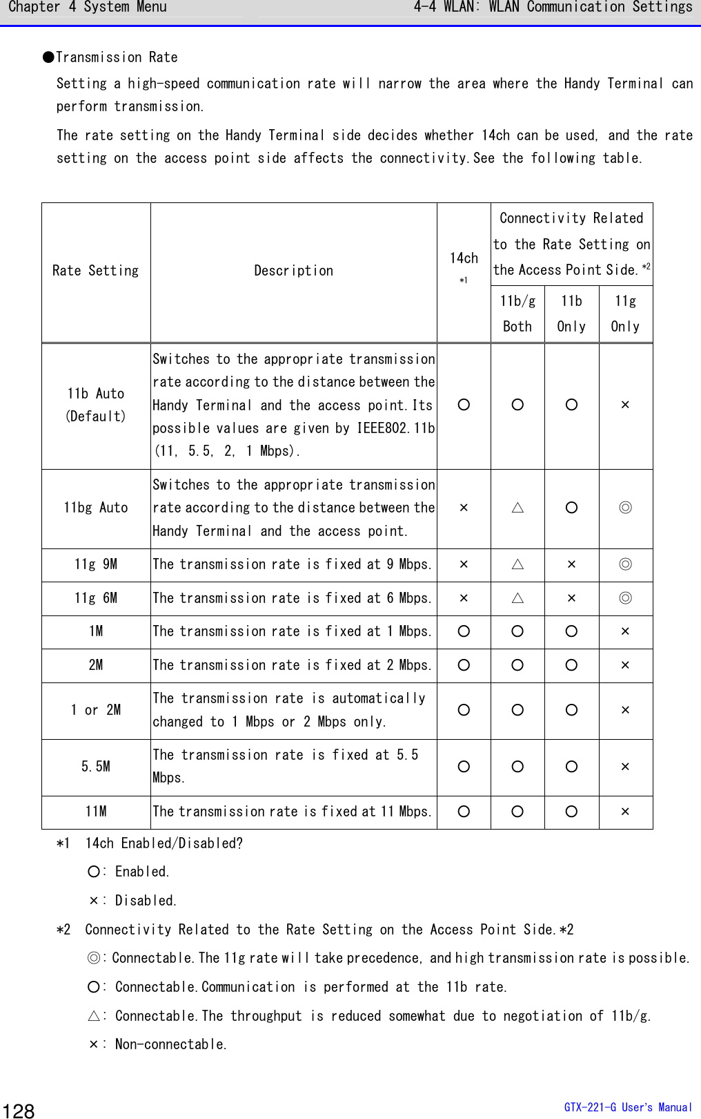
![Chapter 4 System Menu 4-4 WLAN: WLAN Communication Settings GTX-221-G User’s Manual 127 4-4-5 Advanced: Advanced Settings Related to WLAN Communication DHCP You can perform advanced settings related to WLAN. [System Menu]→[2:WLAN]→[5:Advanced] ①Select [Rate control]. < Advanced >1:Rate control[11b Auto]2:RTS Threshold[2347]Bytes ②Select the transmission rate from the list. < Rate(bps) >01b Auto11bg Auto11g 9M11g 6M1M2M1 or 2M5.5M11M You can select the transmission rate from the list. For transmission rate, see the next section. ③Select[RTS_Threshold]. < Advanced >1:Rate control[11b Auto]2:RTS Threshold[2347]Bytes You can set the RTS Threshold value.](https://usermanual.wiki/Welcat/GTX221G/User-Guide-1799364-Page-128.png)
![Chapter 4 System Menu 4-4 WLAN: WLAN Communication Settings GTX-221-G User’s Manual 129 ●RTS Threshold Judges whether the RTS packet can be sent prior to data packet transmission. The RTS packet is sent, and RTS-CTS control is performed if the data packet size is bigger than the setting value. If one access point is connected to multiple terminals, or if the terminals are so remotely distributed that the terminals cannot detect each other even if they can detect the access point, the RTS-CTS control is enabled. The RTS-CTS control is enabled in the above case, but the throughput will be reduced in other cases. Normally, retain the factory setting (2347 bytes). ·Setting range: 0–2347 bytes 4-4-6 MAC address: Displaying the MAC Address You can display the MAC address (hardware specific address). The MAC address cannot be changed. [System Menu]→[2:WLAN]→[6:MAC address] < MAC address >[00:16:41:C1:B9:BD] The MAC address of the Handy Terminal is displayed.](https://usermanual.wiki/Welcat/GTX221G/User-Guide-1799364-Page-130.png)
![Chapter 4 System Menu 4-5 Network: Network Connection Settings GTX-221-G User’s Manual 130 4-5 Network: Network Connection Settings You need to perform the settings required for network connection. [System Menu]→[3:Network] < Network >1:TCP/IP2:DHCP3:FTP4:DNS5:SNMP Select the item to be set. ・TCP/IP: Settings related to TCP/IP communication (P.131) ・DHCP: Settings of DHCP client function (P.133) ・FTP: Settings for using the FTP (P.136). ・DNS: Setting for the DNS server address (P.140) ・SNMP: Various settings for SNMP (P.142)](https://usermanual.wiki/Welcat/GTX221G/User-Guide-1799364-Page-131.png)
![Chapter 4 System Menu 4-5 Network: Network Connection Settings GTX-221-G User’s Manual 131 4-5-1 TCP/IP: TCP/IP Settings DHCP You can perform settings related to TCP/IP communication, starting with IP address. Caution ・While the IP address is [000.000.000.000], WLAN communication cannot be performed. ・Unless "Application boot" is selected in DHCP settings' "■Startup type(P.134)", all the items excluding MTU are read-only and cannot be changed. [System Menu]→[3:Network]→[1:TCP/IP] ① The current settings are displayed. < TCP/IP >1:IP Address[000.000.000.000]2:NetMask[000.000.000.000]3:Gateway[000.000.000.000]4:MTU[1500]Octet](https://usermanual.wiki/Welcat/GTX221G/User-Guide-1799364-Page-132.png)
![Chapter 4 System Menu 4-5 Network: Network Connection Settings GTX-221-G User’s Manual 132 ② Configure the respective items. < TCP/IP >1:IP Address[192.168.254.254]2:NetMask[000.000.000.000]3:Gateway[000.000.000.000]4:MTU[1500]Octet Select the item name to make it ready for input. ・IP Address Sets the IP address assigned by the network administrator. Sets the unique IP addresses of all the GTX-221-Gs connected to the same network. ・NetMask Sets the subnet mask assigned by the network administrator. The subnet mask needs to be set according to the IP address for locating the affiliation of the network. ・Gateway Sets the address of the default gateway. This setting is required when connecting different networks via a router. ・MTU The maximum length of an IP packet. It is usually 1500 octets (bytes) for the Ethernet.When using across a router, this value needs to be changed according to the communication media. For details, contact your network administrator. (Input example) IP address Enter a value in the range 000–255 for each field separated by a period (e.g.,192.168.254.254). Enter the values for "NetMask" and "Gateway" using the same procedure. For settings related to the respective items, contact your network administrator.](https://usermanual.wiki/Welcat/GTX221G/User-Guide-1799364-Page-133.png)
![Chapter 4 System Menu 4-5 Network: Network Connection Settings GTX-221-G User’s Manual 133 4-5-2 DHCP: DHCP Settings DHCP You can configure the DHCP client function that can automatically configure TCP/IP and other various settings. Hint This manual attaches the following mark for system menu items that can be configured automatically from the PC by DHCP. DHCP [System Menu]→[3:Network]→[2:DHCP] Select the item to be set. < DHCP >1:Startup type2:Item not to Update3:Server port[08067]ExecuteF1 ・Startup: Setting of disable/enable DHCP ・Item not to update: Setting of items for which update by DHCP is disabled. ・Server port: Setting of the port number for the DHCP server](https://usermanual.wiki/Welcat/GTX221G/User-Guide-1799364-Page-134.png)
![Chapter 4 System Menu 4-5 Network: Network Connection Settings GTX-221-G User’s Manual 134 ■Startup type You can set to disable/enable DHCP upon startup. [System Menu]→[3:Network]→[2:DHCP]→[1:Startup type] Set the startup type. < Startup type >DisabledApplication bootSystem menu bootAuto wake up boot ・Disabled DHCP will not be executed upon startup. ・Application boot DHCP will be executed before the application software is exe-cuted. When the application software has been selected by[System Menu]→[1:System]→[1:Auto execute], the DHCP function will be executed after the application software has been executed, after startup of the Handy Terminal. In addition, when the application software is started by[5:File]on the system menu, DHCP will not be executed. ・System menu boot DHCP will be executed when the system menu is launched. ・Auto wake up boot DHCP will be executed when auto wakeup is started.](https://usermanual.wiki/Welcat/GTX221G/User-Guide-1799364-Page-135.png)
![Chapter 4 System Menu 4-5 Network: Network Connection Settings GTX-221-G User’s Manual 135 ■Item not to update You can perform settings during execution of the DHCP function so that the specified ter-minal-specific information will not be changed. Caution If IP address is selected (IP address is disabled for update), the IP address set for the Handy Terminal will not be changed.Use this setting after verifying that there are no hosts with the same address in the network. [System Menu]→[3:Network]→[2:DHCP]→[2:Item not to Update] You can select the items whose update you want to disable. <Item not to Update>IP AddressNetMaskGatewayID Checkmark the items whose update you want to disable. ・IP Address ・NetMask ・Gateway ・Terminal ID ■Server port You will need to set the DHCP server port number (factory setting: 08067). [System Menu]→[3:Network]→[2:DHCP]→[3:Server port] < DHCP >1:Startup type2:Item not to Update3:Server port[08067]ExecuteF1 Enter the port number of the DHCP server. This value will be changed when only configuring the IP address using the existing DHCP server without automatically configuring the settings specific to the Handy Terminal. The DHCP server port number is 08067 by default. This is to avoid conflict with other DHCP servers that are being operated in the same network (well-known port number is 67).](https://usermanual.wiki/Welcat/GTX221G/User-Guide-1799364-Page-136.png)
![Chapter 4 System Menu 4-5 Network: Network Connection Settings GTX-221-G User’s Manual 136 4-5-3 FTP: FTP Settings DHCP You need to perform FTP settings when you use the FTP client function. They can also be configured automatically if the DHCP function is enabled. [System Menu]→[3:Network]→[3:FTP] Select the item to be set. < FTP >1:Server Address2:User name[]3:Password4:Advanced ・Server address: Sets the host name of the FTP server ・User name: Sets the login user name for the FTP server ・Password: Sets the login password for the FTP server ・Advanced: Performs advanced FTP settings ■Server address You can set the host name of the FTP server. [System Menu]→[3:Network]→[3:FTP]→[1:Server address] < Server address >1:Set methodAddressName2:Address[000.000.000.000]3:Name IP address or host name specified by "1: Set method" is set as the FTP server. ・When IP address is selected Enter the IP address of the FTP server under "2:Address". ・When host name is selected Enter the host name of the FTP server under "3:Name". Spaces cannot be included in the host name. Caution Perform DNS settings (P.140) if you want to use "Host name".](https://usermanual.wiki/Welcat/GTX221G/User-Guide-1799364-Page-137.png)
![Chapter 4 System Menu 4-5 Network: Network Connection Settings GTX-221-G User’s Manual 137 ■User name You can set the login user name for the FTP server [System Menu]→[3:Network]→[3:FTP]→[2:Name] < FTP >1:Server Address2:User name[ ]3:Password4:Advanced Enter a user name that is case sensitive and consists of up to 18 alphanumeric characters. ■Password You can set the login password for the FTP server [System Menu]→[3:Network]→[3:FTP]→[3:Password] < FTP >1:Server Address2:User name[ ]3:Password4:Advanced Enter a password that is case sensitive and consists of up to 20 alphanumeric characters. Spaces cannot be included in the password. As a security measure, the password entered will be displayed after being converted to an asterisk (*).](https://usermanual.wiki/Welcat/GTX221G/User-Guide-1799364-Page-138.png)
![Chapter 4 System Menu 4-5 Network: Network Connection Settings GTX-221-G User’s Manual 138 ■Advanced You can perform advanced FTP settings. [System Menu]→[3:Network]→[3:FTP]→[4:Advanced] < Advanced >1:Server port[00021]2:ModePassiveActive3:Folder Select the item to be set. ・Server port: Specifies the control port number of the FTP server ・Mode: Specifies the mode ・Folder: Specifies the folder ●Server port Specifies the control port number of the FTP server.It is set to 21 (00021), a well-known FTP number, in factory settings. ●Mode It is set to Passive mode by default.Set it to Active mode if the FTP server does not support Passive mode. Hint The firewall has a setting that denies connection from the outside to the inside. While this setting is enabled, FTP communication is not available in Active mode. Using Passive mode allows you to perform communication with an FTP server located on the other side of the firewall.](https://usermanual.wiki/Welcat/GTX221G/User-Guide-1799364-Page-139.png)
![Chapter 4 System Menu 4-5 Network: Network Connection Settings GTX-221-G User’s Manual 139 ●Folder You can specify the transmission/reception folders of the FTP server. < Folder >1:Current[/(Root) ]2:Specified ・Current Select [Current]to display the submenu. Select the current folder from the following items: /(Root) The root folder of the FTP server. The user name folder may be specified as the root folder, depending on the FTP server. /(User name) Sets the user name folder in the root folder of the FTP server as the current folder.If the user name has not been set, executing the FTP function (file transmission/reception) will lead to an error screen. /(Specified) Sets the relative path from the root folder set as "Specified" (see the next item) as the current folder. ・Specified Select [Specified], and enter the folder name. The text set here will be added to the FTP method of "CWD". As the text set here is directly used for FTP communication, the file path must be correctly entered. (Ex.) "dir1/dir2/dir3" Spaces cannot be included in the specified folder.](https://usermanual.wiki/Welcat/GTX221G/User-Guide-1799364-Page-140.png)
![Chapter 4 System Menu 4-5 Network: Network Connection Settings GTX-221-G User’s Manual 140 4-5-4 DNS: DNS Server Settings DHCP You can set the address of the DNS server. [System Menu]→[3:Network]→[4:DNS] Select the item to be set. < DNS >1:Primary[000.000.000.000]2:Secondary[000.000.000.000]3:Advanced ・Primary: Sets the IP address of the primary DNS server ・Secondary: Sets the IP address of the secondary DNS server ・Advanced: Performs advanced settings for DNS ■Primary This is used to set the IP address of the primary DNS server. [System Menu]→[3:Network]→[4:DNS]→[1:Primary] < DNS >1:Primary[000.000.000.000]2:Secondary[000.000.000.000]3:Advanced Enter the IP address of the primary DNS server.](https://usermanual.wiki/Welcat/GTX221G/User-Guide-1799364-Page-141.png)
![Chapter 4 System Menu 4-5 Network: Network Connection Settings GTX-221-G User’s Manual 141 ■Secondary This is used to set the IP address of the secondary DNS server. [System Menu]→[3:Network]→[4:DNS]→[2:Secondary] < DNS >1:Primary[000.000.000.000]2:Secondary[000.000.000.000]3:Advanced Enter the IP address of the secondary DNS server. ■Advanced You can perform advanced settings for DNS [System Menu]→[3:Network]→[4:DNS]→[3:Advanced] < Advanced >1:Server port[00053]2:Timeout time[01]sec3:Trial count[1]4:Cache time[0003]min Select and set the item. ・Server port Specifies the control port number of the DNS server. The well-known port number is 53. ・Timeout time Sets the response packet latency within 1 - 99 seconds. ・Trial count Sets the number of retries.If it is set to 0, only one packet will be sent, and no retry will be performed. ・Cache time Its setting range is 0 - 9999 minutes.If it is set to 0, the cache function will be disabled.The maximum number of entries at the cache table is 8. If the maximum value is exceeded, the old entry is erased and a new entry is created.](https://usermanual.wiki/Welcat/GTX221G/User-Guide-1799364-Page-142.png)
![Chapter 4 System Menu 4-5 Network: Network Connection Settings GTX-221-G User’s Manual 142 4-5-5 SNMP: SNMP Setting DHCP You can perform various settings for SNMP. The settings can also be made automatically if the DHCP function is enabled. [System Menu]→[3:Network]→[5:SNMP] Select the item to be set. < SNMP >1:Community(R/Only)2:Community(R/W)3:Trap4:Advanced ・Community (R/Only): Sets the read-only community ・Community (R/W): Sets the read-write community ・Trap: Sets the Trap community ・Advanced: Performs advanced settings for SNMP ■Community (R/Only) You can set the read-only community name. [System Menu]→[3:Network]→[5:SNMP]→[1:Community(R/Only)] <Community(R/Only)>1:Community name[public ]2:Manager IP address[000.000.000.000] Select and set the item. ・Community name The community name is specified using up to 16 alphanumeric characters. The actions allowed by this community name are "Read-Only". GET and GET-NEXT requests are supported by this community name. When SET request is performed by this community, an authentication trap will be sent. ・Manager IP address Sets the IP address of the SNMP manager that is enabled using the community name set at[Community name]. When the IP address is set to "000.000.000.000", this community name is enabled for all the SNMP managers.](https://usermanual.wiki/Welcat/GTX221G/User-Guide-1799364-Page-143.png)
![Chapter 4 System Menu 4-5 Network: Network Connection Settings GTX-221-G User’s Manual 143 ■Community (R/W) You can set the read-write community name. [System Menu]→[3:Network]→[5:SNMP]→[2:Community(R/W)] < Community(R/W) >1:Community name[private ]2:Manager IP address[000.000.000.000] Select and set the item. ・Community name The community name is specified using up to 16 alphanumeric characters. The actions allowed by this community name are "Read-Write". GET, GET-NEXT, and SET requests are supported by this community name. ・Manager IP address Sets the IP address of the SNMP manager that is enabled using the community name set at[Community name]. When the IP address is set to "000.000.000.000", this community name is enabled for all the SNMP managers. ■Trap You can set the Trap community name. [System Menu]→[3:Network]→[5:SNMP]→[3:Trap] < Trap >1:Community name[Welcat ]2:Manager IP address[000.000.000.000] Select and set the item. ・Community name You can set the Trap community name. The community name is specified using up to 16 alphanumeric characters. ・Manager IP address Sets the IP address of the SNMP manager, which is the transmission destination of Trap. When the IP address is set to "000.000.000.000", no trap will be sent.](https://usermanual.wiki/Welcat/GTX221G/User-Guide-1799364-Page-144.png)
![Chapter 4 System Menu 4-5 Network: Network Connection Settings GTX-221-G User’s Manual 144 ■Advanced You can perform advanced settings for SNMP. [System Menu]→[3:Network]→[5:SNMP]→[4:Advanced] < Advanced >1:Authentic trapSend2:Agent port[00161]3:Trap port[00162]4:Trap retry[1] Select and set the item. ・Authentic trap Sets whether to "Send" Authentic trap when access is found to be from other than the community name and the manager IP address set on "1: Community (R/Only)" or "2: Community (R/W)". This trap is sent to the SNMP manager set on "2: Manager IP address". ・Agent port Sets the SNMP manager and the communication port number. It is set to 161 (00161), a well-known SNMP number, in the factory settings. ・Trap port The trap port number for sending the trap.The well-known port number is 162. ・Trap retry Specifies the number of times for resending the Trap.](https://usermanual.wiki/Welcat/GTX221G/User-Guide-1799364-Page-145.png)
![Chapter 4 System Menu 4-5 Network: Network Connection Settings GTX-221-G User’s Manual 145 ●About SNMP ・The Handy Terminal can perform management using "Network Administration Tool" included in "WebGlider Integration Server" (WGS-001). ・SNMP-PDU (Protocol Data Unit) is compliant with SNMPv1. ・The Handy Terminal manages the objects of the following MIB groups: [1.3.6.1.2.1.1] MIB2-System [1.3.6.1.2.1.2] MIB2-Interfaces [1.3.6.1.2.1.4] MIB2-IP [1.3.6.1.2.1.5] MIB2-ICMP [1.3.6.1.2.1.6] MIB2-TCP [1.3.6.1.2.1.7] MIB2-UDP [1.3.6.1.2.1.11] MIB2-SNMP [1.3.6.1.4.1.12392] Welcat Enterprise MIB Welcat Enterprise MIB is described in ASN.1 format. Welcat Enterprise MIB is included in "WebGlider Integration Server" (for more information, contact our sales office). ・Supported Traps Trap Description Cold Start Sent during communication start after MIB is initialized.MIB is ini-tialized upon power on. However, initialization will not be performed when recovered from resume. Warm Start When sent during a communication start other than Cold Start.*1 Link up Sent when the Handy Terminal has been synchronized with the access point. However, Link up is not sent when synchronization with the access point is first realized (ColdStart and Warm Start were sent).It is also sent on reaching synchronization when the Handy Terminal enters from outside to inside the range of communication, or when synchronization with a new access point is reached by roaming (same timing with signal SIGRFU_INSYNC). Link down Sent upon termination of communication.However, it is not sent when outside the range. Authentication When an attempt is made to access the Handy Terminal, this trap is sent to the IP address set on "Trap-Manager IP address" (P. 143) However, it is sent only when "Send" is checkmarked at "Trap-Authentic trap" (P.144) on the system menu. *1 Even if the MIB-related settings (such as IP address, subnet mask, default gateway) are changed, MIB will not be initialized. Therefore, instead of Cold Start, Warm Start will be sent. To initialize MIB, restart the Handy Terminal.](https://usermanual.wiki/Welcat/GTX221G/User-Guide-1799364-Page-146.png)
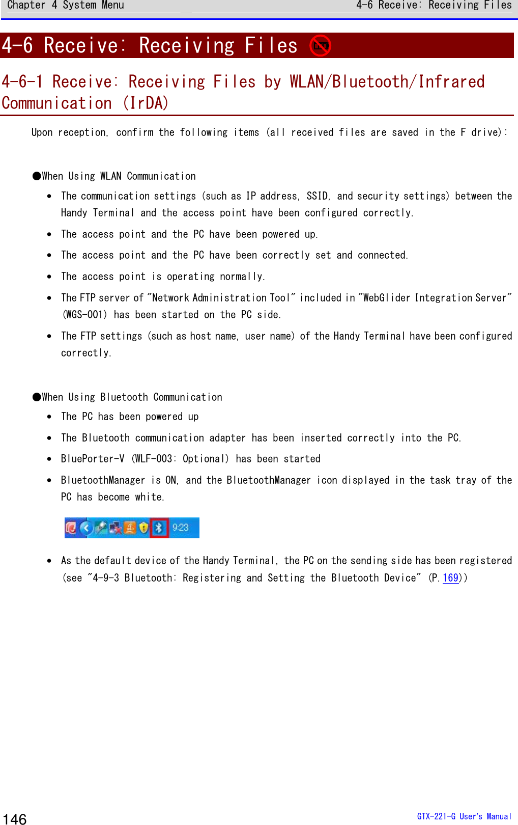
![Chapter 4 System Menu 4-6 Receive: Receiving Files GTX-221-G User’s Manual 147 ●When Using Infrared Communication (IrDA) Upon reception, confirm the following items: ■When the Sending Side Is a PC ・The PC has been powered up ・The "BluePorter-V" (WLF-003: Optional) has been started on the PC. ・The Handy Terminal has been set to the USB communication unit, and infrared communication has been enabled (see "3-4 Building Infra-red Communication (IrDA) Environment" (P.81)) ■When the sending side is XIT-2xx series ・Can be sent using "wait (HT)" ・ Communicate with reference to communication between Handy Terminals in "3-4 Building Infra-red Communication (IrDA) Environment" (P.81) [System Menu]→[4:Receive] Select the communication means for reception. < Device type >1:WLAN2:Bluetooth3:IrDA Select the reception method. ・WLAN ・Bluetooth ・IrDA](https://usermanual.wiki/Welcat/GTX221G/User-Guide-1799364-Page-148.png)
![Chapter 4 System Menu 4-6 Receive: Receiving Files GTX-221-G User’s Manual 148 ■Receiving Files (WLAN) [System Menu]→[4:Receive]→[1:WLAN] ① Get the file list, and select the files to be received. < File list >SAMPLE1.OUTSAMPLE2.OUTReceive MenuF1 F2 Select the files to be received by checkmarking their names. Press the【F1】key to display the reception confirmation dialog. In such as case, if there is no checkmarked file, the selected file will be received. Select[Yes]/[No]. Full nameAll checks appliedAll checks removed Press the【F2】key to display the submenu for operating the file list. Change the settings as needed. ・Full name Displays the full name of each selected file. ・All checks applied Selects all the checkboxes in the file list. ・All checks removed Clears all the checkboxes in the file list.](https://usermanual.wiki/Welcat/GTX221G/User-Guide-1799364-Page-149.png)
![Chapter 4 System Menu 4-6 Receive: Receiving Files GTX-221-G User’s Manual 149 ② Reception starts. < 受信中 >sam p le1 .OU T000010 / 000021 The reception status is displayed on the screen. A file named“SAMPLE1.OUT”already exists.Would you like toreplace it?YES NO If there are files with the same names as the files to be received, an overwriting confirmation dialog will be displayed. Select[Yes]/[No]. ③ Reception takes place. CompletedOK Upon completion of reception, [ (Number of Reception Suc-cesses/Number of Checks)]will be displayed in the message box. Press the【ENT】key.](https://usermanual.wiki/Welcat/GTX221G/User-Guide-1799364-Page-150.png)
![Chapter 4 System Menu 4-6 Receive: Receiving Files GTX-221-G User’s Manual 150 ■Receiving Files (Bluetooth/IrDA) [System Menu]→[4:Receive]→[2:Bluetooth]/[3:IrDA] ① Select the reception method. < Receiving method >1:Select from list2:wait(PC)3:wait(HT) Select "Select from list" to get the file list from the sending side. The receiving side can select the files to be received from the list.→Procedure② Select "2:Wait (PC)"/"3:Wait (HT)" to enter the reception wait state immediately. If the sending side is a PC, select "2:Wait (PC)"; if it is XIT-2xx, select "3: Wait (HT)"Files to be received depend on the sending side.→Procedure③ * "Wait (PC)" is a function that can be used by BluePorter in Bluetooth communication. It cannot be used by BluePorter-V. ②Select the files to be received. < File list >SAMPLE1.OUTSAMPLE2.OUTExecute MenuF1 F2Would you like toreceive it?YES NO Select the files to be received by checkmarking their names, and then press the【F1】Key. The reception confirmation dialog is displayed.If there is no checkmarked file, the selected file will be received. Select[Yes]/[No]. Full nameAll checks appliedAll checks removed Press the【F2】key to display the submenu for operating the file list. Change the settings as needed. ・Full name Displays the full name of each selected file. ・All checks applied Selects all the checkboxes in the file list. ・All checks removed Clears all the checkboxes in the file list.](https://usermanual.wiki/Welcat/GTX221G/User-Guide-1799364-Page-151.png)
![Chapter 4 System Menu 4-6 Receive: Receiving Files GTX-221-G User’s Manual 151 ③ Reception starts. < Receiving >sample1.OUT000010 / 000021 The reception status is displayed on the screen. A file named“SAMPLE1.OUT”already exists.Would you like toreplace it?YES NO If there are files with the same names as the files to be received, an overwriting confirmation dialog will be displayed. Select[Yes]/[No]. ④ Reception takes place. CompletedOK Upon completion of reception, [ (Number of Reception Suc-cesses/Number of Checks)]will be displayed in the message box. Press the【ENT】key.](https://usermanual.wiki/Welcat/GTX221G/User-Guide-1799364-Page-152.png)
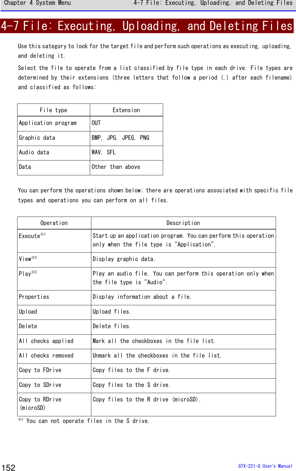
![Chapter 4 System Menu 4-7 File: Executing, Uploading, and Deleting Files GTX-221-G User’s Manual 153 ※2 Supported graphic data is as follows: Format BMP, JPG, JPEG, PNG Size Maximum 480×640 pixels (Display area: 240×296 pixels) ※3 Supported audio data is as follows: Extension WAV Format Windows standard WAVE format Audio sampling rate 8000/11025/16000/22050/44100/48000[Hz] Channel Monophonic Audio sample size 16bit Audio method PCM Extension SFL Format Audio file list (text format) Maximum number of files listed 32 Explanation By using a SFL file, you can continuously play multiple audio files. List filenames in a file list by separating each with a line feed. A maximum of 32 filenames can be listed. Listed audio files should be stored in the product in advance. Each file whose name is listed in a file list is played only once. If an error occurs during playback, the subsequent audio files will not be played. You cannot list names of other SFL files in a SFL file. Description example ALARM_MELODY.WAV (line feed) LOCATION_3F_2.WAV (line feed) SHIP_ERROR.WAV](https://usermanual.wiki/Welcat/GTX221G/User-Guide-1799364-Page-154.png)
![Chapter 4 System Menu 4-7 File: Executing, Uploading, and Deleting Files GTX-221-G User’s Manual 154 [System Menu]→[5: File] ① Select the drive. < Drive type >1:FDrive2:SDrive3:RDrive(microSD) Select the drive to operate. ② Select the file type (for a drive other than the RDrive). < File type >ApplicationDataAudioGraphicAll type Select the type of file to operate. When "All type" is selected, regardless of file type, all the files stored in the drive will be included. ③ Mark the file to operate. < FDrive >132X128.JPGCOPAN1.JPGCOPAN2.JPGHABANERO.JPGKOUME1.JPGKOUME2.JPGMAKE.TXTMenuF1 Select the file and press the【ENT】key to mark and unmark the checkbox for that file. There are two types of operation: operation to target the marked file and operation to target the selected file.](https://usermanual.wiki/Welcat/GTX221G/User-Guide-1799364-Page-155.png)
![Chapter 4 System Menu 4-7 File: Executing, Uploading, and Deleting Files GTX-221-G User’s Manual 156 ■Execute: Execute an Application Program [System Menu]→[5:File]→[Application]→Select the drive→[F1 Menu] →[Execute] Execute the selected file. Would you like toregister with“Auto execute”?YES NO The file being selected (highlighted) will be executed (regardless of whether its checkbox is marked). Press the【ENT】key to execute the file. If the application program to execute is not registered in Auto execute, a registration confirmation dialog box appears. To terminate the application program executed, perform the op-eration specified for each application program. After termination, whether to display the system menu again or to turn the main unit's power OFF depends on the application program. If the battery pack runs out of power during operation, the main unit's power is turned off after displaying an alarm. If you want to forcibly terminate the application program, hold down the【PW】key for 10 seconds while the application program is running. ■Play: Play Audio Data [System Menu]→[5: File]→[Audio]→Select the drive→[F1 Menu]→[Play] Play the audio data. < Audio >Playing ...Stop The audio file being selected will be played (regardless of whether its checkbox is marked). Press the【C】key to stop playing the file. ■View: Display Graphic Data](https://usermanual.wiki/Welcat/GTX221G/User-Guide-1799364-Page-157.png)
![Chapter 4 System Menu 4-7 File: Executing, Uploading, and Deleting Files GTX-221-G User’s Manual 157 [System Menu]→[5:File]→ Select the drive →[Graphic]→[F1 Menu]→[View] Display and check the graphic data. The image in the file being selected (highlighted) will be displayed (regardless of whether its checkbox is marked). Press any key to return to the "File Operation Menu". ■Properties: Display Detailed Information of a File [System Menu]→[5:File]→ Select the drive → Select the file type → [F1 Menu]→[Properties] Check detailed information of the file. < File Property >NameSAMPLE1.OUTType[Application]Library[1.00]Size[00000000]BytesModified2012/01/0100:00:00 The following information will be displayed: ・Name ・Type ・Size ・Modified Information about the file being selected (highlighted) will be displayed (regardless of whether its checkbox is marked). Press any key to return to the <File> screen.](https://usermanual.wiki/Welcat/GTX221G/User-Guide-1799364-Page-158.png)
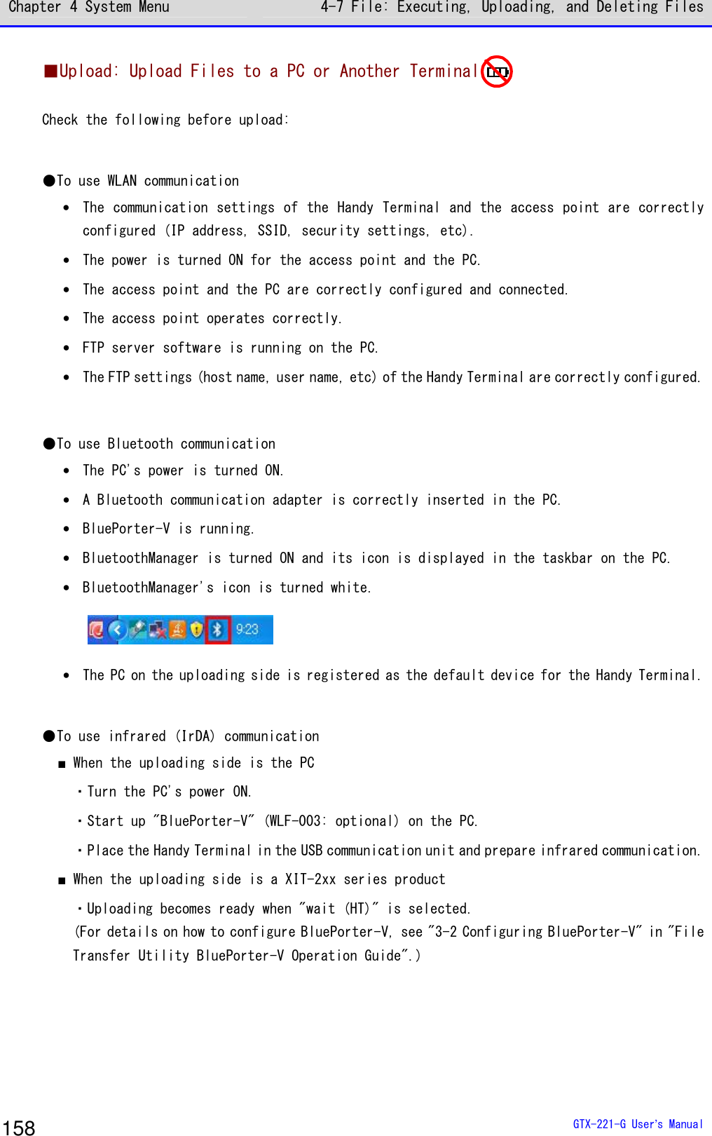
![Chapter 4 System Menu 4-7 File: Executing, Uploading, and Deleting Files GTX-221-G User’s Manual 159 [System Menu]→[5:File]→ Select the drive→Select the file type →[F1 Menu] →[Upload] ① The marked file(s) will be uploaded. < FDrive >123X128.JPGCOPAN1.JPGSAMPLE1.OUTSAMPLE2.OUTHABANERO.JPGMAKE.TXTMenuF1 Select and mark the file(s) to upload. If there is no marked file, the file being selected will be uploaded. Press the【F1】key, select [Upload], and press the【ENT】key. ② Select the upload method. < Device type >1:WLAN2:Bluetooth3:IrDA Select the upload method. ・WLAN ・Bluetooth ・IrDA ③ Uploading will start. < 送信中 >sam p le1 .OU T0847872 / 2101161 The upload status is displayed on the screen.](https://usermanual.wiki/Welcat/GTX221G/User-Guide-1799364-Page-160.png)
![Chapter 4 System Menu 4-7 File: Executing, Uploading, and Deleting Files GTX-221-G User’s Manual 160 ④ Finish the uploading process. CompletedOK When the uploading process becomes complete, "(# of successfully uploaded files/# of marked files)" will be displayed in the message box. Press the【ENT】key. ■Delete: Delete Files [System Menu]→[5:File]→ Select the drive → Select the file type → [F1 Menu]→[Delete] Delete the marked file(s). If there is no marked file, the file being selected (highlighted) will be deleted. Would you like todelete this file?YES NO< File delete > A confirmation dialog box appears. Select [Yes] or [No].](https://usermanual.wiki/Welcat/GTX221G/User-Guide-1799364-Page-161.png)
![Chapter 4 System Menu 4-7 File: Executing, Uploading, and Deleting Files GTX-221-G User’s Manual 161 ■All Checks Applied: Select All Files [System Menu]→[5:File]→ Select the drive → Select the file type → [F1 Menu]→[All checks applied] All the checkboxes will be marked. < File >132X128.JPGCOPAN1.JPGCOPAN2.JPGHABANERO.JPGKOUME1.JPGKOUME2.JPGMAKE.TXTMenuF1 ■All Checks Removed: Deselect All Files [System Menu]→[5:File]→ Select the drive → Select the file type → [F1 Menu]→[All checks removed] All the checkboxes will be unmarked. < File >132X128.JPGCOPAN1.JPGCOPAN2.JPGHABANERO.JPGKOUME1.JPGKOUME2.JPGMAKE.TXTMenuF1](https://usermanual.wiki/Welcat/GTX221G/User-Guide-1799364-Page-162.png)
![Chapter 4 System Menu 4-7 File: Executing, Uploading, and Deleting Files GTX-221-G User’s Manual 162 ■Copy to the Specified Drive [System Menu]→[5:File]→ Select the drive → Select the file type → [F1 Menu]→ Select the copy destination drive Copy files to the specified drive. Would you like tocopy this file?YES NO< File Copy > A confirmation dialog box appears. Select [Yes] or [No].](https://usermanual.wiki/Welcat/GTX221G/User-Guide-1799364-Page-163.png)
![Chapter 4 System Menu 4-8 ID: Setting the Terminal Identification ID GTX-221-G User’s Manual 163 4-8 ID: Setting the Terminal Identification ID Use this category to set an ID number for terminal identification to each product. Set a number unique to each product. [System Menu]→[6: ID] Set an ID unique to your terminal. < ID >ID [000] You can enter an ID number in the range 000-999.](https://usermanual.wiki/Welcat/GTX221G/User-Guide-1799364-Page-164.png)
![Chapter 4 System Menu 4-9 Device: Setting Hardware Functions GTX-221-G User’s Manual 164 4-9 Device: Setting Hardware Functions Use this category to set hardware devices such as a barcode Handy Terminal and keys. Setting items in the device category are classified by device type. [System Menu]→[7: Device] Select the hardware device to configure. < Device >1:Barcode2:Key3:Bluetooth4:Display5:Tone/Vibrator Select the item to set. ・Barcode: Configure the barcode Handy Terminal (P.164). ・Key: Set the key operation (P.168). ・Bluetooth: Register and Set the Bluetooth device(P.169). ・Display: Set the backlight luminosity(P.177). ・Tone/Vibrator: Set the tone, LED, and vibrator(P.178). 4-9-1 Barcode: Configuring the Barcode Scanner [System Menu]→[7: Device]→[1: Barcode] Select the barcode Handy Terminal function to set. < Barcode Scanner >1:Trigger mode2:Version3:Picklist mode4:Inverse(1D) Make a selection from the following items: ・Trigger mode: Set the image Handy Terminal operating conditions. ・Version: Display the version of decoding. ・Picklist mode: Set the Picklist mode (targeted scan function). ・ Inverse(1D): Set the scanning of black-and-white-inverted barcode.](https://usermanual.wiki/Welcat/GTX221G/User-Guide-1799364-Page-165.png)
![Chapter 4 System Menu 4-9 Device: Setting Hardware Functions GTX-221-G User’s Manual 165 ■Trigger Mode Use this item to set the irradiation time. This setting is enabled only in application programs using "Trigger mode" for barcode scanning. [System Menu]→[7: Device]→[1: Barcode]→[1: Trigger mode] < Trigger mode >1:Trigger operation[Normal]2:Power saving[Full]3:Irradiation time[20]sec ①Select[Trigger operation]. NormalDoubleReleaseAuto Set the trigger key operation and the irradiation pattern. You can scan barcodes while laser light is being irradiated (lighted). ・Normal Press the Trigger key to irradiate laser light. ・Double Press the Trigger key to make laser light start blinking. Press the key again to irradiate laser light. ・Release Press the Trigger key to make laser light start blinking, and release the key to irradiate laser light. ・Auto Automatically irradiate laser light regardless of trigger operation.](https://usermanual.wiki/Welcat/GTX221G/User-Guide-1799364-Page-166.png)
![Chapter 4 System Menu 4-9 Device: Setting Hardware Functions GTX-221-G User’s Manual 166 ②Select[Power saving]. FullQuickNone Make a setting to suppress power consumption during scan. ・Full Automatically turn the laser light off after finishing a barcode scan and stop supplying power to the Handy Terminal section, too. The power consumption can be reduced, but it takes time to start the next scan. ・Quick Automatically turn the laser light off after finishing a barcode scan but continue supplying power to the Handy Terminal section. The power consumption is a little greater than when Full is selected, but you can smoothly proceed to the next scan. ・None Do not use the Power saving mode. ③Select the[Irradiation time]. < Trigger mode >1:Trigger operation[Normal]2:Power saving[Full]3:Irradiation time[20]sec Set a time period until the laser light is automatically turned OFF. You can set a value in the range 00-60 seconds. When 00sec. is set, the laser light will not be turned OFF and continue to be irradiated.](https://usermanual.wiki/Welcat/GTX221G/User-Guide-1799364-Page-167.png)
![Chapter 4 System Menu 4-9 Device: Setting Hardware Functions GTX-221-G User’s Manual 167 ■Version Display the version of decoding. [System Menu]→[7: Device]→[1: Barcode]→[2: Version] < Version >PAAAAC07-001-N02 4620 ■Picklist Mode Set the Picklist mode (targeted scan function). [System Menu]→[7: Device]→[1: Barcode]→[3: Picklist mode] < Picklist mode >DisabledEnabled Select between "Enabled" and "Disabled". ・Enabled Scan symbols in the scan area according to their priorities. The center of the aimer is the easiest area to scan symbols. ・Enabled Scan only barcodes in the center of a cross aiming pattern.](https://usermanual.wiki/Welcat/GTX221G/User-Guide-1799364-Page-168.png)
![Chapter 4 System Menu 4-9 Device: Setting Hardware Functions GTX-221-G User’s Manual 168 ■Inverted barcode [System Menu]→[7: Device]→[1: Barcode]→[4: Inverse(1D)] < Inverse(1D) >Regular onlyInverse onlyAuto detect Set the scanning of inverted barcodes. ・Regular only Scan barcodes where the bar is black and the space is white. ・Inverse only Scan inverted barcodes where the normal black bar is white and the normal white space is black. ・Auto detect Scan both regular and inverted barcodes. 4-9-2 Key: Setting the Key Repeat By holding one of the arrow keys (【⊳】【】【】【】), you can repeat inputting that key while doing so. This section describes how to set the time between when a arrow key starts to be held down and when the first key-input repetition is performed (Key repeat delay) and how to set the interval of subsequent key-input repetitions (Key repeat rate). Example: When the key repeat delay is set to 1 second. and the key repeat rate is set to 500 milliseconds. Start holdingthe keyFirstkey-inputSecondkey-inputThirdkey-inputDuringholdingthekey↑ ↑ ↑ ↑1second1.5second0.5second0second2second [System Menu]→[7: Device]→[2: Key] < Key >1:Key repeat delay[0500] ms2:Key repeat rate[0100] ms The effective range is 0100-1000 milliseconds. When 0000 milliseconds is set, it is prohibited to repeat key input.](https://usermanual.wiki/Welcat/GTX221G/User-Guide-1799364-Page-169.png)
![Chapter 4 System Menu 4-9 Device: Setting Hardware Functions GTX-221-G User’s Manual 169 4-9-3 Bluetooth: Registering and Setting the Bluetooth Device [System Menu]→[7: Device]→[3: Bluetooth] Select the setting target device. < Bluetooth >1:Local device2:Remote device ・Local device: Set the Handy Terminal. ・Remote device: Set a device to connect to the Handy Terminal. ■Local Device Display the BD address of the Handy Terminal. [System Menu]→[7: Device]→[3: Bluetooth]→[1: Local device] < Prooerty >1:Device nameXIT-2202:BD Address[00:00:00:00:00:00]3:Security4:VersionSaveF1 Set the following: ・Device name ・Security "BD Address" is fixed; you cannot change its details. Would you like tosave settings?YES NO The details set for each item will not be saved automatically. To save the setting details, press the【F1】key or the【C】key on this screen and select [Yes] on a confirmation dialog box. Hint Only when Local device is currently set, a search from a remote device is allowed. Otherwise, no search will be allowed.](https://usermanual.wiki/Welcat/GTX221G/User-Guide-1799364-Page-170.png)
![Chapter 4 System Menu 4-9 Device: Setting Hardware Functions GTX-221-G User’s Manual 170 ①Select [Device name], < Prooerty >1:Device nameXIT-2202:BD Address[00:00:00:00:00:00]3:Security4:VersionSaveF1 Enter the name of the Bluetooth device. The device name should be a value up to 30 alphanumeric and symbol characters and case-sensitive. ②Select [Security]. < Security >Pairing EnablePIN code[ ] Make settings related to authentication for connection. When this checkbox is marked, perform authentication when a connection request is made to the local device from a remote device. Only authenticated remote devices are permitted to connect to the local device. < Security >Pairing EnablePIN code[ ] Set the PIN code. The PIN (Personal Identification Number) code is a password used for authentication. You can enter a value up to 16 characters using uppercase and lowercase alphabet, numeric, and symbol characters. The entered PIN code is displayed hidden beneath the asterisks (*).](https://usermanual.wiki/Welcat/GTX221G/User-Guide-1799364-Page-171.png)
![Chapter 4 System Menu 4-9 Device: Setting Hardware Functions GTX-221-G User’s Manual 171 ③Select [Version]. < Version >hci : 2.0hr : 0x0m5mImp : 2.0man : csrIs : 0x0m5m Check the version of the built-in Bluetooth device's firmware. ■Remote Device Make settings related to devices (remote devices) to connect to the Handy Terminal. [System Menu]→[7: Device]→[3: Bluetooth]→[2: Remote device] < Remote device >1:Device list2:Search for devices3:Search option ・Device list: Register remote device information. ・Search for devices: Search for remote devices around the Handy Terminal. ・Search option: Set the number of devices to search for through Search for devices.](https://usermanual.wiki/Welcat/GTX221G/User-Guide-1799364-Page-172.png)
![Chapter 4 System Menu 4-9 Device: Setting Hardware Functions GTX-221-G User’s Manual 172 ●Device list For information about remote devices to connect to, you can register a maximum of seven entries. When such information has been registered in advance, you do not have to set device information for each connection. [System Menu]→[7: Device]→[3: Bluetooth]→[2: Remote device] →[1: Device list] ① Select an item number to make registration. < Device list >1:(No Device)2:(No Device)3:(No Device)4:(No Device)5:(No Device)6:(No Device)7:(No Device)MenuF1 Select an item number and set device information to it in sequence. When device information has already been registered, a device name is displayed to the right of an item number. If nothing is reg-istered, "(No Device)" is displayed to the right of an item number. (Note that device information is recognized as already registered when the entered device name is equal to or longer than one character and the entered BD address is any value other than "00:00:00:00:00:00"). A device with a checkmark displayed to the left of its item number is the default device. In the System Menu, to use Bluetooth communication, connect to the default device. DefaultErase Press the【F1】key to display the submenu. Set the following as needed: ・Default Set the registered device being selected, as the default device. ・Erase Erase the registered device information. ② Select the item to set. < Prooerty >1:Device nameXIT-2202:BD Address[00:03:7A:0B:0A:AB]3:SecuritySave SearchF1 F2 Set the following items, press the【F1】key, and select [Yes] to save the settings. ・Device name ・BD Address ・Security](https://usermanual.wiki/Welcat/GTX221G/User-Guide-1799364-Page-173.png)
![Chapter 4 System Menu 4-9 Device: Setting Hardware Functions GTX-221-G User’s Manual 173 ③ Select [Device name]. < Prooerty >1:Device nameXIT-2202:BD Address[00:03:7A:0B:0A:AB]3:Security4:VersionSave SearchF1 F2 Enter the name of the Bluetooth device. Set this item, press the【F1】key, and select [Yes] to save the settings. The device name should be a value up to 30 alphanumeric and symbol characters and case-sensitive. ④ Select [BD Address]. < Prooerty >1:Device nameXIT-2202:BD Address[00:03:7A:0B:0A:AB]3:Security4:VersionSave SearchF1 F2 Enter the BD address. Set this item, press the【F1】key, and select [Yes] to save the settings. The BD address is an hardware address unique to a device. It is a fixed 12 hexadecimal-digit number (0-9, A-F). ⑤ Select [Security]. < Security >Pairing EnablePIN code[ ] Set the authentication for connection. When this checkbox is marked, perform authentication when a connection request is made to the local device from a remote device. Only authenticated remote devices are permitted to connect to the local device. < Security >Pairing EnablePIN code[******** ] Set the PIN code. The PIN(Personal Identification Number) code is a password used for authentication. You can enter a value up to 16 characters using uppercase and lowercase alphabet, numeric, and symbol characters. For security, the entered PIN code is displayed after being converted into asterisks (*).](https://usermanual.wiki/Welcat/GTX221G/User-Guide-1799364-Page-174.png)
![Chapter 4 System Menu 4-9 Device: Setting Hardware Functions GTX-221-G User’s Manual 174 ●Search for devices Search for remote devices around the Handy Terminal. You can set detected remote devices as registered devices. Hint If you want to include other terminals as targets of Search for devices, you need to keep target devices as "Local device currently set". "Local device currently set" indicates the status of the <Property> screen in the local device settings. [System Menu]→[7: Device]→[3: Bluetooth]→[2: Remote device] →[2: Search for devices] ①A search starts. <Search for devices>Searching ... Press the【C】key to cancel the search. ②Search results are displayed in list form. < Search results >USB-AdaptorLabel-PrinterPropertyF1 The names of detected remote devices are displayed in list form. Hint Device names in alphanumeric and symbol characters can be detected. Do not use kana or kanji characters for device names.](https://usermanual.wiki/Welcat/GTX221G/User-Guide-1799364-Page-175.png)
![Chapter 4 System Menu 4-9 Device: Setting Hardware Functions GTX-221-G User’s Manual 175 < Property >Device nameUSB-AdaptorBD Address[00:00:00:00:00:00] Press the【F1】key to display the device name and BD address of the remote device being selected. Press the【C】key to return to the <Search results> screen. ③Register the detected remote device. < Search results >USB-AdaptorLabel-PrinterPropertyF1Remote1Remote2Remote3Remote4Remote5Remote6Remote7 Select the remote device to register and press the【ENT】key to display the submenu. Select the remote number to register the remote device to, and the device will be registered. The remote hasbeen alreadyregistered.Would you like tooverwrite it?YES NO If you select the already registered remote device number, a confirmation dialog box for overwriting appears. Select [Yes] or [No].](https://usermanual.wiki/Welcat/GTX221G/User-Guide-1799364-Page-176.png)
![Chapter 4 System Menu 4-9 Device: Setting Hardware Functions GTX-221-G User’s Manual 176 ●Search option Set the maximum number of remote devices to be detected through Search for devices. [System Menu]→[7: Device]→[3: Bluetooth]→[2: Remote device] →[3: Search option] < Search option >Search MAX [9] (1-9) Specify the number of devices to search for. You can set a value in the range 1-9 for the number of devices. The greater the number of devices to search for, the longer the search duration becomes.](https://usermanual.wiki/Welcat/GTX221G/User-Guide-1799364-Page-177.png)
![Chapter 4 System Menu 4-9 Device: Setting Hardware Functions GTX-221-G User’s Manual 177 4-9-4 Setting the Display/Backlight Luminosity Set luminosity: [System Menu]→[7: Device]→[4: Display] < Display >1:Luminosity2:SetAlsSensor Make a selection from the following items: ・Luminosity: Adjust the backlight luminosity. ・SetAlsSensor: Set automatic backlight dimming. ■Luminosity [System Menu]→[7: Device]→[4: Display]→[1: Luminosity] < Luminosity >F6(High)Level : 2F7(Low) 【▲】key is used to move the slider up and the【▼】key is used to move the slider down to adjust luminosity.. You can set luminosity in four steps; move the slider and luminosity changes in real-time. Level Luminosity High Bright Low Dark](https://usermanual.wiki/Welcat/GTX221G/User-Guide-1799364-Page-178.png)
![Chapter 4 System Menu 4-9 Device: Setting Hardware Functions GTX-221-G User’s Manual 178 ■Light Sensor [System Menu]→[7: Device]→[4: Display]→[2: Light Sensor] < Light Sensor >Enabled Enable Ambient Light Sensor. When Ambient Light Sensor is enabled, the luminosity setting will be disabled. 4-9-5 Tone/Vibrator: Setting the Volume, LED, and the Vibrator Use this category to set the volume, LED, and vibrator. [System Menu]→[7: Device]→[5: Tone/Vibrator] Select the device to set. < Tone/Vibrator >1:Volume2:Indicator func3:Click Sound Make a selection from the following items: ・Volume ・Indicator func ・Click Sound](https://usermanual.wiki/Welcat/GTX221G/User-Guide-1799364-Page-179.png)
![Chapter 4 System Menu 4-9 Device: Setting Hardware Functions GTX-221-G User’s Manual 179 ■Volume [System Menu]→[7: Device]→[5: Tone/Vibrator]→[Volume] Adjust the volume of the buzzer sound. < Volume >F6(Up)Level : 4F7(Down) You can adjust the volume in eight steps from level 1 to 8. 【】key moves the slider up and the【】key moves the slider down. As the slider moves up and down, the volume changes in real-time; you can check the current level on the spot. The relationship between the level and the volume is as follows: Level Volume 8 Bigger 1 Smaller When 1 is set, the buzzer sound is silenced. ■Indicator Func Indicator func is a generic term indicating a combination of three devices alerting the operator (buzzer/vibrator/LED). Using Indicator func, the current situation can better appeal to the senses of the operator. Set which indicator should be used in what situation to suit each application. Three patterns are available for each of the following six scenes: five typical scenes of operation such as pressing (clicking) a key and entering data, and one arbitrary scene that can be set by the customer (user). Note that the indicators for pattern 3 of each scene apply to the system menu. For example, • When data is entered, generate one short high tone and light the green LED ON • When an error occurs, generates three low tones while operating the vibrator and blink the red LED As shown in this example, various settings can be made to suit the customer's use environment.](https://usermanual.wiki/Welcat/GTX221G/User-Guide-1799364-Page-180.png)
![Chapter 4 System Menu 4-9 Device: Setting Hardware Functions GTX-221-G User’s Manual 180 [System Menu]→[7: Device]→[5: Tone/Vibrator]→[2: Indicator func] ① Select the indicator to set. < Indicator func >1:Cancel-12:Cancel-23:Cancel-34:Enter-15:Enter-26:Enter-37:Click-18:Click-29:Click-3MenuF1 Icons indicating the current indicator settings are displayed in the bottom right of the screen. : Buzzer enabled. : Audio enabled. : Vibrator enabled. : LED enabled. PreviewInitializeInitialize all Press the【F1】key to display the submenu. ・Preview You can actually feel the current indicator settings. ・Initialize Discard the settings for the selected pattern and restore the initial settings. ・Initialize all Discard the settings for all the patterns for all the scenes and restore the initial settings. ② Select the device to set. < Device >1:Buzzer2:Audio3:Vibrator4:LED After selecting the item to set on the screen in step ①, and press the【ENT】key to display the device name. Select the device to set and press the【ENT】key. Set the operating conditions for each device by referring to the next section.](https://usermanual.wiki/Welcat/GTX221G/User-Guide-1799364-Page-181.png)
![Chapter 4 System Menu 4-9 Device: Setting Hardware Functions GTX-221-G User’s Manual 181 ●Device operating conditions setting There are operating conditions common to all devices and operating conditions specific to each device. [System Menu]→[7: Device]→[5: Tone/Vibrator]→[2: Indicator func] → Select the device. Operation common to all devices < Buzzer >EnabledFreq. [0580]HzON [00040]msOFF [00000]msRepeat[00]MenuF1 Turn ON/OFF the relevant device operation using the check box for it. Mark the check box to enable the relevant device operation, and unmark it to disable it regardless of other settings. This setting is displayed as an icon. PreviewInitialize Press the【F1】key to display the submenu. Set as needed. ・Preview You can actually feel the current indicator settings. ・Initialize Discard the settings for the pattern currently set and restore the initial settings. Note that when【F1】is displayed in the bottom left of the screen, the operation procedure is the same for all device operation conditions.](https://usermanual.wiki/Welcat/GTX221G/User-Guide-1799364-Page-182.png)
![Chapter 4 System Menu 4-9 Device: Setting Hardware Functions GTX-221-G User’s Manual 182 Set the buzzer frequency ([1: Buzzer]). < Buzzer >EnabledFreq. [0580]HzON [00040]msOFF [00000]msRepeat[00]MenuF1 Move the cursor over[Freq.]and press the【ENT】key. The cursor moves to the frequency value. The setting range is 245-9000Hz. You can set the frequency in units of 1Hz within this frequency range. Due to the characteristics of the speaker, we recommend using the buzzer at a frequency in the range 500-3000Hz. Low toneMediantHigh tone While entering the frequency, the content in the function key guidance in the lower left of the screen changes. Press the【F1】key to display the frequency sample submenu. You can smoothly set the frequency by fine-adjusting the value based on the sample. Set the LED color ([4:LED]). < LED >EnabledColor [Red ]ON [00500]msOFF [00000]msRepeat[00]MenuF1 Move the cursor over [Color] and press the【ENT】key. RedGreenOrange Select a color from the submenu.](https://usermanual.wiki/Welcat/GTX221G/User-Guide-1799364-Page-183.png)
![Chapter 4 System Menu 4-9 Device: Setting Hardware Functions GTX-221-G User’s Manual 183 ■Click Sound Set whether to generate a click sound when a key is pressed. A click sound plays immediately when a key is pressed. For that reason, the sound of an application program or of an indicator can be interrupted by a click sound. Depending on the timing, the sound may become unclear due to such an interruption. [System Menu]→[7: Device]→[5: Tone/Vibrator]→[3: Click Sound] Select a pattern for the sound to play when a key is pressed. < Click Sound >NoneBeepBeep + AudioAudio ・None (Default) Do not generate a click sound. ・Beep For every key, generate a short beep sound when a key is pressed. ・Beep + Audio Read a number when a numeric key is pressed. Generate a beep sound when any other key is pressed. ・Audio Read a number only when a numeric key is pressed. Do not generate any sound when any other key is pressed.](https://usermanual.wiki/Welcat/GTX221G/User-Guide-1799364-Page-184.png)
![Chapter 4 System Menu 4-10 Management: Setting Basic Information and Management GTX-221-G User’s Manual 184 4-10 Management: Setting Basic Information and Management Use this category to check basic information of, improve the performance of, and perform maintenance of the Handy Terminal. [System Menu]→[8: Manage] Select the item to manage. < Management >1:System info2:Format3:Clone4:Drive5:Mothball6:Wizard7:OS Update Select the item to set. ・System info: Check the OS version (P.184). ・Format: Format the registry/drive (P.185). ・Clone: Create a copy (P.187). ・Drive: Display the drive information (P.195). ・Mothball: Settings when not using the product for long (P.196). ・ Wizard: Start up the screen facilitating configuration of communication settings (P.197). ・OS Update: Update the OS of the Handy Terminal (P198.) 4-10-1 System info: Checking the OS Version Display the version information of the installed OS. [System Menu]→[8: Manage]→[1: System info] Check the OS version. < System info > O S : 01.03.04](https://usermanual.wiki/Welcat/GTX221G/User-Guide-1799364-Page-185.png)
![Chapter 4 System Menu 4-10 Management: Setting Basic Information and Management GTX-221-G User’s Manual 185 4-10-2 Format: Registry/Drive Formatting Format the registry or drives. Caution When formatting is performed, the factory default settings will be restored and all the files will be deleted. When formatting, with the above in mind, be very careful. [System Menu]→[8: Manage]→[2: Format] ① Select the item to format. < Format >RegistryInitializeFDriveSDriveRDrive(microSD)Execute MenuF1 F2 Mark the checkbox for the item to format. If none of the checkboxes is marked, you cannot perform formatting. All checks appliedAll checks removed Press the【F2】key to display the submenu. ・All checks applied Mark all the checkboxes. ・All checks removed Unmark all the checkboxes.](https://usermanual.wiki/Welcat/GTX221G/User-Guide-1799364-Page-186.png)
![Chapter 4 System Menu 4-10 Management: Setting Basic Information and Management GTX-221-G User’s Manual 186 ② Start formatting. If Format wasexecuted,all settings andall files wouldbe deleted.Would you like toexecute Format?YES NO Press the【F1】key, and an execution confirmation dialog box appears. Select [Yes] or [No]. < Format >RegistryInitializeFDriveSDriveRDrive(microSD)Formatting ... The items with their checkboxes marked will be formatted in sequence. ③ Finish formatting. CompletedOK Press the【ENT】key to finish formatting. If the registry is initialized, the power will be turned OFF.](https://usermanual.wiki/Welcat/GTX221G/User-Guide-1799364-Page-187.png)
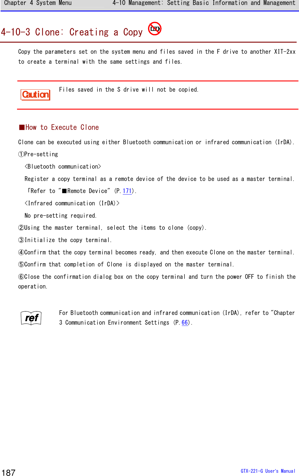
![Chapter 4 System Menu 4-10 Management: Setting Basic Information and Management GTX-221-G User’s Manual 188 Caution When executing Clone, thoroughly understand the following and be very careful. ・When the radio condition is bad during Bluetooth communication, or when the surrounding environment is bad such as light disturbance during infrared communication not, even if copying cannot be performed correctly, "Completed" may be displayed on the master side. ・The content inside a copy terminal is initialized before reception from the master terminal. For that reason, if Clone fails, the factory default settings may be restored or all the files may be deleted. ・Since a copy terminal is initialized first, it may take time to become ready to perform Clone on it. ■Bluetooth/IrDA [System Menu]→[8: Manage]→[3: Clone] ① Select the communication method. < Device type >1:Bluetooth2:IrDA3:microSD Select between Bluetooth or IrDA (infrared). ・Bluetooth ・IrDA ② Set whether the Handy Terminal is a master terminal or copy terminal. < Clone >1:Master2:Copy ・Master: When the product is a copy source XIT-2xx. ・Copy: When the product is a copy destination XIT-2xx.](https://usermanual.wiki/Welcat/GTX221G/User-Guide-1799364-Page-189.png)
![Chapter 4 System Menu 4-10 Management: Setting Basic Information and Management GTX-221-G User’s Manual 189 ●Master: The Handy Terminal is a copy source. Select the settings and files to copy and execute Clone. [System Menu]→[8: Device]→[3: Clone]→[1: Bluetooth/2: IrDA] →[1: Master] ① Select the items to clone. < Clone(master) >SystemSecurityUserUniqueFDriveExecute MenuF1 F2 Select the items to copy. Confirm that the copy terminal has been completely initialized and is waiting for connection, press the【F1】key to start executing Clone. All checks appliedAll checks removed Press the【F2】key to display the submenu. Set an item as needed. ・All checks applied Mark all the checkboxes. ・All checks removed Unmark all the checkboxes. ② Finish the Clone operation. CompletedOK Press the【ENT】key to finish the Clone operation.](https://usermanual.wiki/Welcat/GTX221G/User-Guide-1799364-Page-190.png)
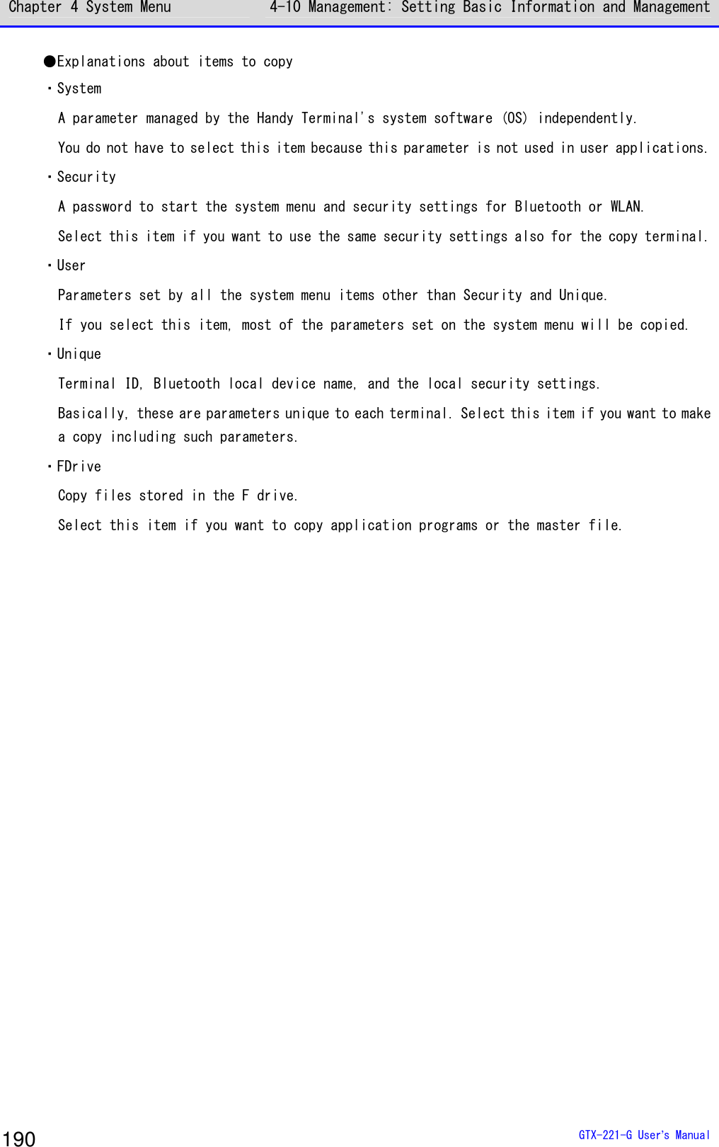
![Chapter 4 System Menu 4-10 Management: Setting Basic Information and Management GTX-221-G User’s Manual 191 ●Copy: The Handy Terminal is a copy destination. [System Menu]→[8: Manage]→[3: Clone]→[1: Bluetooth/2: IrDA] →[2: Copy] ① Initialize the Handy Terminal. < Clone(copy) >If Clone wasexecuted,all settings andall files wouldbe deleted.Would you like toexecute Clone?YES NO Execute before executing Clone on the master terminal (pressing the【F1】key.) An execution confirmation dialog box appears. Select [Yes] or [No]. ② You are notified that the Clone is ready to execute. The Clone isready to execute.OK Press the【ENT】key to wait for connection. At this point, execute Clone on the master terminal (press the【F1】key). ③ Check the screen on the master terminal. Please check thatthe master iscompleted.OK Completion of Clone cannot be confirmed on the copy terminal. Be sure to confirm on the screen on the master terminal that the transfer operation has been completed. If you find on the master terminal that the transfer operation has not been completed, execute Clone again. Press the【ENT】key.](https://usermanual.wiki/Welcat/GTX221G/User-Guide-1799364-Page-192.png)
![Chapter 4 System Menu 4-10 Management: Setting Basic Information and Management GTX-221-G User’s Manual 192 ④ Finish the Clone operation. ShutdownOK Press the【ENT】key. The power is turned OFF. ■microSD [System Menu]→[8: Manage]→[3: Clone] ① Select the method. < Device type >1:Bluetooth2:IrDA3:microSD Select microSD. ② Specify whether the Handy Terminal is on the export side or on the import side. < Clone >1:Export2:Import ・Export: When the product is a copy source XIT-2xx. ・Import: When the product is a copy destination XIT-2xx.](https://usermanual.wiki/Welcat/GTX221G/User-Guide-1799364-Page-193.png)
![Chapter 4 System Menu 4-10 Management: Setting Basic Information and Management GTX-221-G User’s Manual 193 ●Export: The Handy Terminal is a copy source. Select the settings and files to copy and execute Clone. [System Menu]→[8: Manage]→[3: Clone]→[3: microSD]→[1: Export] ① Select the items to clone. < Clone(Export) >SystemSecurityUserUniqueFDriveExecute MenuF1 F2 Select the items to copy. All checks appliedAll checks removed Press the【F2】key to display the submenu. Set an item as needed. ・All checks applied Mark all the checkboxes. ・All checks removed Unmark all the checkboxes. ② Finish the Clone operation. CompletedOK Press the【ENT】key to finish the Clone operation.](https://usermanual.wiki/Welcat/GTX221G/User-Guide-1799364-Page-194.png)
![Chapter 4 System Menu 4-10 Management: Setting Basic Information and Management GTX-221-G User’s Manual 194 ●Import: The Handy Terminal is a copy destination. [System Menu]→[8: Manage]→[3: Clone]→[3: microSD]→[2: Import] ① Confirm execution. < Clone(Import) >If Clone wasexecuted,all settings andall files wouldbe deleted.Would you like toexecute Clone?YES NO An execution confirmation dialog box appears. Select [Yes] or [No]. ② Clone will be executed. Please do notremove a batteryby any means! Do not turn the power OFF during execution. ③ Finish the Clone operation. ShutdownOK Press the【ENT】key. The power is turned OFF.](https://usermanual.wiki/Welcat/GTX221G/User-Guide-1799364-Page-195.png)
![Chapter 4 System Menu 4-10 Management: Setting Basic Information and Management GTX-221-G User’s Manual 195 4-10-4 Drive: Displaying Drive Information Use this item to check information about drives and perform their maintenance. [System Menu]→[8: Manage]→[4: Drive] ① Select the drive. < Drive selection >1:FDrive2:SDrive3:RDrive(microSD) Select the drive and press the【ENT】key. ② The drive property is displayed. < FDrive Property >Capacity[20578304]BytesUsed space[ 205393]BytesFree space[20372911]BytesFiles[ 4 / 128]DefragF1 The following information will be displayed: ・Capacity ・Used space ・Free space ・Files NormalDeep For the F drive, press the【F1】key to optimize it by defragmentation. Press the【F1】key, and a dialog box appears. ・Normal Physically eliminate unneeded regions created while files are written to or deleted. ・Deep In addition to defragmentation in Normal mode, reorganize the secured free regions so that they become contiguous. It may take several seconds to several minutes to complete defragmentation in Deep mode depending on the drive's condition. Normally, we recommend executing defragmentation in Normal mode.](https://usermanual.wiki/Welcat/GTX221G/User-Guide-1799364-Page-196.png)
![Chapter 4 System Menu 4-10 Management: Setting Basic Information and Management GTX-221-G User’s Manual 196 Caution Never remove the battery pack during defragmentation. If the battery or the battery pack is removed during defragmentation, files or system programs may be destroyed. Hint If files are repeatedly written to or deleted on the F drive, the free space is gradually fragmented, and eventually, it may become impossible to store large files or it may take long to start up. To prevent the F drive from fragmentation, be careful about the following: ・Write data collectively as contiguous data as much as possible. ・When finishing operation, delete the data temporarily stored on the F drive. ・For data that needs to be temporarily stored, try to write it to the S drive. 4-10-5 Mothball: Settings When Not Using the Product For Long When not using the Handy Terminal for a long period of time, configure settings to suppress battery consumption. Execute Resume and erase the S drive. [System Menu]→[8: Manage]→[5: Mothball] ① Resume is executed and the S drive is erased. < Mothball >The contents ofresume and theSdrive are deletedinstead ofsuppressingconsumption of abackup battery.YES NO An execution confirmation dialog box appears. Select [Yes] or [No].](https://usermanual.wiki/Welcat/GTX221G/User-Guide-1799364-Page-197.png)
![Chapter 4 System Menu 4-10 Management: Setting Basic Information and Management GTX-221-G User’s Manual 197 ② Finish Mothball preparation. Completed.Shutdown.OK Press the【ENT】key. The power is turned OFF. Hint When the power is turned ON after Mothball, the message "The SDrive has been initialized." appears, but it is not a defect (refer to"1-2-7 Long-term Storage" (P.52)). 4-10-6 Wizard: Starting the Screen Facilitating Configuration of Communication Settings Use this item to start again the setting wizard executed when the Handy Terminal was started for the first time. You can configure the settings minimally required for communication between the Handy Terminal and a PC. [System Menu]→[8: Manage]→[6: Wizard] Configure settings using Wizard. < Wizard >Start wizard?Communication set-ting can be donewith guidanceYES NO Select [Yes] or [No]. Select [Yes] to execute the wizard to set WLAN communication. Select [No] to return to the previous screen. For details, refer to "■WLAN Communication Settings by Setting Wizard" (P.70).](https://usermanual.wiki/Welcat/GTX221G/User-Guide-1799364-Page-198.png)
![Chapter 4 System Menu 4-10 Management: Setting Basic Information and Management GTX-221-G User’s Manual 198 4-10-7 OS Update: Updating the OS of TheHandy Terminal Update the OS of the Handy Terminal. [System Menu]→[8: Manage]→[7: OS Update] ① Start updating the OS. < OS Version UP >XIT2XX-OS v01.00.00Mon 01 201200:00:00Updating tothis OS starts.F1:OK F2:CAN Press the【F1】key to start updating the OS. Press the【F2】key to stop updating the OS. ② The Handy Terminal restarts and the OS update process starts. < OS Update >OS installationis in progress.Please wait ... Never remove the battery back during OS update. And, do not press any key. ③ Restart the product. OS update hasbeen completed.Hit any keyto start new OS. After the OS update has been completed, press any key. This turns the power OFF.](https://usermanual.wiki/Welcat/GTX221G/User-Guide-1799364-Page-199.png)
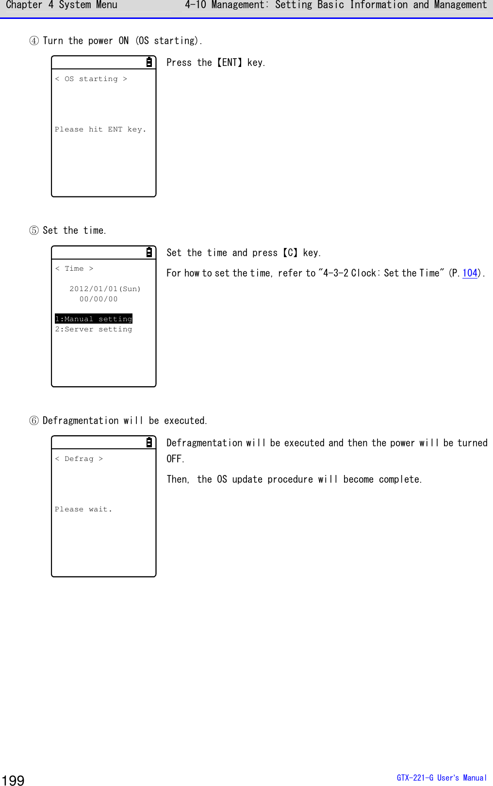
![Chapter 4 System Menu 4-11 Test: Testing Hardware Devices GTX-221-G User’s Manual 200 4-11 Test: Testing Hardware Devices Use this category to operate hardware devices for testing their conditions. [System Menu]→[9: Test] Select the device to test. < Test >1:WLAN2:Bluetooth3:IrDA4:Barcode5:Display6:Key Make a selection from the following items: ・WLAN: Test WLAN communication (P.200). ・Bluetooth: Test Bluetooth communication (P.204). ・IrDA: Test infrared (IrDA) communication (P.205). ・Barcode: Test barcode scanning (P.206). ・Display: Test LCD screen display (P.207). ・Key: Test key operations and indicators (P.208). 4-11-1 WLAN: Testing WLAN Communication Perform WLAN communication-related and IP network communication tests. [System Menu]→[9: Test]→[1: WLAN] Select the item to set. < WLAN Test >1:Configuration2:WLAN/ping test3:AP Search Make a selection from the following items: ・Configuration: Configure the ping command execution conditions. ・WLAN/ping test: Test WLAN communication using the ping command. ・AP Search: Search for access points in the neighborhood.](https://usermanual.wiki/Welcat/GTX221G/User-Guide-1799364-Page-201.png)
![Chapter 4 System Menu 4-11 Test: Testing Hardware Devices GTX-221-G User’s Manual 201 ■Configuration Configure the ping command execution conditions. WLAN communication will be tested while sending the ping command. [System Menu]→[9: Test]→[1: WLAN]→[1:Configuration] < Configuration >1:Host address[000.000.000.000]2:Packet size[1472]Bytes3:Timeout time[003]sec4:Trial count[004] Configure the WLAN test conditions. ・Host address Specify the IP address of the target device whose communication condition you want to check. ・Packet size (Default=1472 bytes) Select the size (bytes) of a data packet to send. Settable values: 32, 64, 128, 256, 512, 1024, and 1472 ・Timeout time (Default=3 seconds) Set the timeout time in seconds. Settable values: 1 to 255 seconds ・Trial count(Default=four times) Set the number of times to send the ping command. Settable values: 1 to 255 times When 0 is specified, continue to send the ping command until the【C】key is pressed.](https://usermanual.wiki/Welcat/GTX221G/User-Guide-1799364-Page-202.png)
![Chapter 4 System Menu 4-11 Test: Testing Hardware Devices GTX-221-G User’s Manual 202 ■WLAN/ping test Execute the ping command to test WLAN communication. Continue to send the ping command to the host IP address set in Configuration. The following details will be displayed: the ping command result, the MAC address of the synchronized access point, communication quality (LnkQ), the strength of received radio signals (ASL), and the channel used. [System Menu]→[9: Test]→[1: WLAN]→[2:WLAN/ping test] < WLAN/ping >Host=000.000.000.000Time < 000.000 msecNo.00000 1472BytesLnkQ CH:11ASL AP_MAC[000000000000] The following information will be displayed: <1st line> The title of this test <2nd line> The host IP address to send the ping command to <4th line> Displays the result. When successful Displays the time expended to obtain the result.(Unit: msec) Timeout Displays "ping Timeout". When stopped by pressing the【C】key. Displays "Stopped". <5th line> Transmission packet number (incremented by 1) and transmitted bytes <6th line> Displays the LnkQ indicator. LnkQ indicates the communication quality between the product and the access point. <7th line> Displays the currently synchronized channel. <8th line> Displays the ASL indicator. ASL indicates the strength of radio signals received from the access point. <10th line> Displays the MAC address of the access point connected via WLAN communication. Hint ・To obtain stable communication performance, we recommend that the level of the LnkQ indicator should be 4 or higher. ・For PSK (TKIP/CCMP), an error message appears when authentication fails. ・The LnkQ indicator in the 6th line and the ASL indicator in the 8th line do not show radio signal strengths accurately. Consider them as approximate radio conditions.](https://usermanual.wiki/Welcat/GTX221G/User-Guide-1799364-Page-203.png)
![Chapter 4 System Menu 4-11 Test: Testing Hardware Devices GTX-221-G User’s Manual 203 ■AP Search Search for access points that match the SSID set in the Handy Terminal. By setting the SSID of the Handy Terminal as "ANY", you can search for all the access points in the neighborhood. Hint Note that the above is effective only when access points are configured to respond to "ANY". From the viewpoint of security, response to "ANY" is disabled in some access points. The details to be displayed as search results are the MAC addresses, channels, and SSIDs of the matched access points. [System Menu]→[9: Test]→[1: WLAN]→[3: AP Search] < Search results >00A0F850D7D3 0100A0F850D7F4 0600A0F850D7CE 11PropertyF1 Search results will be displayed after several seconds or several tens of seconds. <1st line> The title of test results <3rd line and after> The MAC addresses and channel numbers of detected access points <10th line> Key guidance to display SSID. SSID : XIT220OK Press the【F1】key to display the SSID set to the currently selected access point. Would you like toset SSID toXIT220?YES NO When the access point is selected, a confirmation dialog box appears, so that you can set the SSID that is set to the access point into the Handy Terminal.](https://usermanual.wiki/Welcat/GTX221G/User-Guide-1799364-Page-204.png)
![Chapter 4 System Menu 4-11 Test: Testing Hardware Devices GTX-221-G User’s Manual 204 4-11-2 Bluetooth: Testing Bluetooth Communication Perform one-to-one communication with another terminal via Bluetooth.. Before executing Bluetooth communication, you have to set the target device as the default device. (The target device means a slave device or terminal when your device is set as Master, or a master device when your device is set as Slave.) 「Refer to "4-9-3 Bluetooth: Registering and Setting the Bluetooth Device"-"■Remote device" (P.171). [System Menu]→[9: Test]→[2: Bluetooth] ① Set the Handy Terminal as Master or Slave. < Role >1:Master2:Slave Select the method for connection with the Bluetooth device to communicate to. A master has the initiative in connection, and a slave follows the instructions of its master. Connection is possible only between a master and a slave. Start a test based on the following: when the local device is a master, the other device is its slave, and when the local device is a slave, the other device is its master. Note that this master-slave relationship applies just temporarily at the time of connection. The master-slave relationship will disappear after connection. ② A communication test starts. < Bluetooth test >123456 When a key is pressed, the corresponding key data is sent and at the same time, it is also displayed on the screen (local echo). When the data is received at the other end, it is highlighted on the screen.](https://usermanual.wiki/Welcat/GTX221G/User-Guide-1799364-Page-205.png)
![Chapter 4 System Menu 4-11 Test: Testing Hardware Devices GTX-221-G User’s Manual 205 4-11-3 IrDA: Testing Infrared Communication Perform one-to-one communication with another terminal via Infrared communication. [System Menu]→[9: Test]→[3: IrDA] An infrared communication test starts. < IrDA test >000000 Place the infrared communication ports of your device and another terminal so that they face each other, and start infrared com-munication also on that terminal. When a key is pressed, the corresponding key data is sent and at the same time, it is also displayed on the screen (local echo). When the data is received at the other end, it is highlighted on the screen.](https://usermanual.wiki/Welcat/GTX221G/User-Guide-1799364-Page-206.png)
![Chapter 4 System Menu 4-11 Test: Testing Hardware Devices GTX-221-G User’s Manual 206 4-11-4 Barcode Perform a barcode scanning test. Note that barcode input here will not be affected by the trigger mode. [System Menu]→[9: Test]→[4: Barcode] When the scan mode arises, press the【SCAN】key or the Trigger key to scan a barcode. ●Barcode scanning < Barcode test >4901744551846JAN13 13BytesHEX OptionF1 F2 Scan a barcode. The scanned barcode, barcode type, and the number of digits will be displayed. ●Display through character code conversion < Barcode test >34393031373434353531383436JAN13 13BytesASCII OptionF1 F2 Press the【F1】key to display the scanned data through character code conversion. ・ASCII(Default) Display the scanned data by converting it into ASCII characters. ・HEX Display the scanned data by converting it into hexadecimal values. Through hexadecimal conversion, one character is displayed using two hexadecimal digits such as "35" for "5" and "6D" for "m". Press the【F1】key to alternate the display methods. ■Barcode Option < Barcode option >1:Check digit2:JAN/EAN/UPC3:Composite Press the【F2】key to set barcode option items. Note that the settings made here are enabled during barcode test only.](https://usermanual.wiki/Welcat/GTX221G/User-Guide-1799364-Page-207.png)
![Chapter 4 System Menu 4-11 Test: Testing Hardware Devices GTX-221-G User’s Manual 207 ●Check digit Set whether to check the check digit. • Check Enable not marked (Default) Do not check the check digit. • Check Enable marked Check the check digit. ●JAN/EAN/UPC Set the scanning condition for add-on codes of JAN/EAN/UPC. • Ignore Add-on (Default) Do not scan add-on codes. • Read all Allow JAN/EAN/UPC to be scanned regardless of whether add-on codes exist. • Read Add-on only Allow only JAN/EAN/UPC with add-on codes to be scanned. ●Composite Set the scanning condition for Composite. • Prohibition (Default) Do not allow Composite to be scanned. • Permission Allow Composite to be scanned. 4-11-5 Display: Testing the LCD Screen Test the screen display condition. [System Menu]→[9: Test]→[5: Display] A test pattern is displayed. Display test startsHit any key. Test the LCD display condition. Each time a key other than【F4】and【PW】is pressed, the LCD screen changes its color one after another. When you finish displaying all colors, you return to the previous operation.](https://usermanual.wiki/Welcat/GTX221G/User-Guide-1799364-Page-208.png)
![Chapter 4 System Menu 4-11 Test: Testing Hardware Devices GTX-221-G User’s Manual 208 4-11-6 Key: Testing Key Operations and Indicators Test key input operations as well as indicators (buzzer/vibrator/LED). [System Menu]→[9: Test]→[6: Key] < Key test >F1 F2TF3 F4 F5 F6 F7 F8L R1 2 3 4 5c.SF6 7BS PH8 9 0 When a key is pressed, the icon for that key displayed above the partition line in the middle of the screen is highlighted (for the【ENT】key only, its icon, which is highlighted by default, ceases to be highlighted), and the icon corresponding to the pressed key is displayed below the partition line (local echo). And, in conjunction with each key, the indicators corresponding to it operate. The indicators assigned to each key are as follows: Key Buzzer Vibrator LED Audio playback 【0】~【9】,【・】 ○ × Green × 【ENT】,【C】. 【BS】,【SF】 ○ × Orange × 【SCAN】 × ○ Orange × 【F1】 ○ × Red Melody 【F2】 ○ × Red Voice (Scan the barcode.) 【F3】 ○ × Red Voice (Charge the battery.) 【F4】 ○ × Red Voice (An error occurred.) 【⊳】(【F5】) ○ × Red Voice (Five) 【】(【F6】) ○ × Red Voice (Six) 【】(【F7】) ○ × Red Voice (Seven) 【】(【F8】) ○ × Red Voice (Eight) When the【C】key has been pressed twice or when every key has been pressed, the test becomes complete. Hint You cannot operate the【PW】key until you finish testing all the keys.](https://usermanual.wiki/Welcat/GTX221G/User-Guide-1799364-Page-209.png)

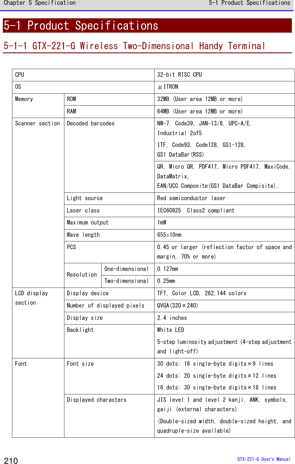
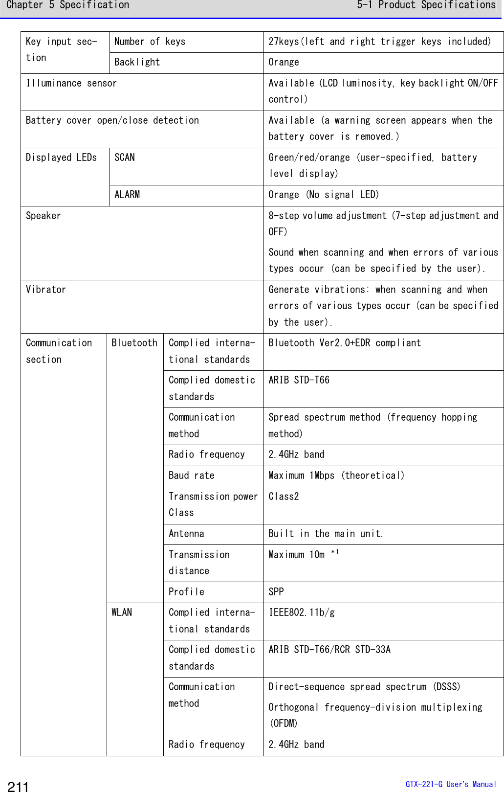
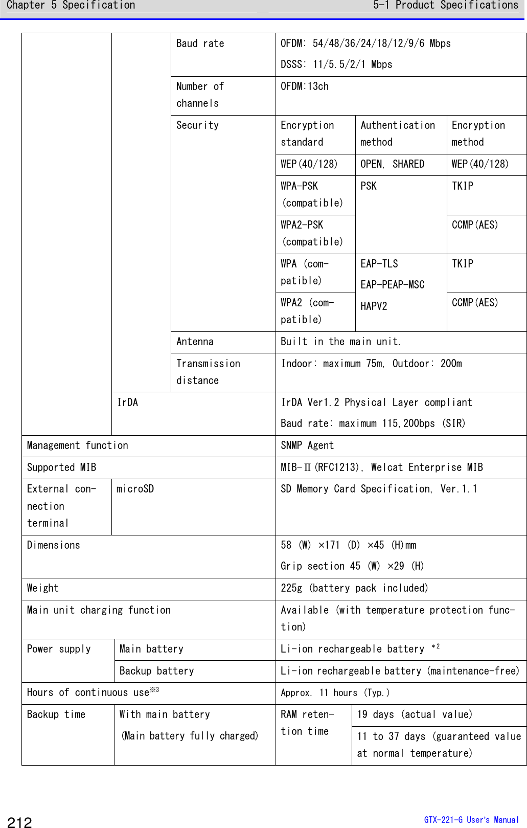
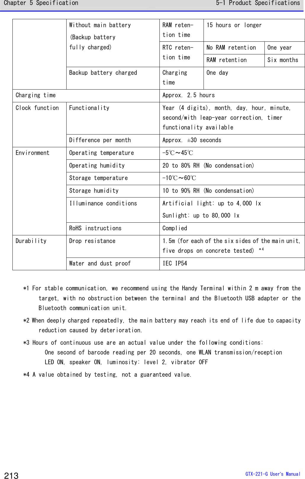
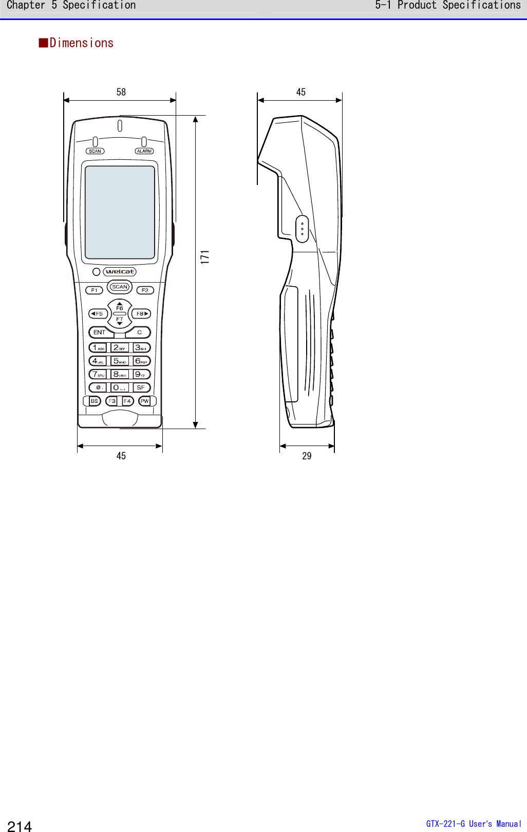
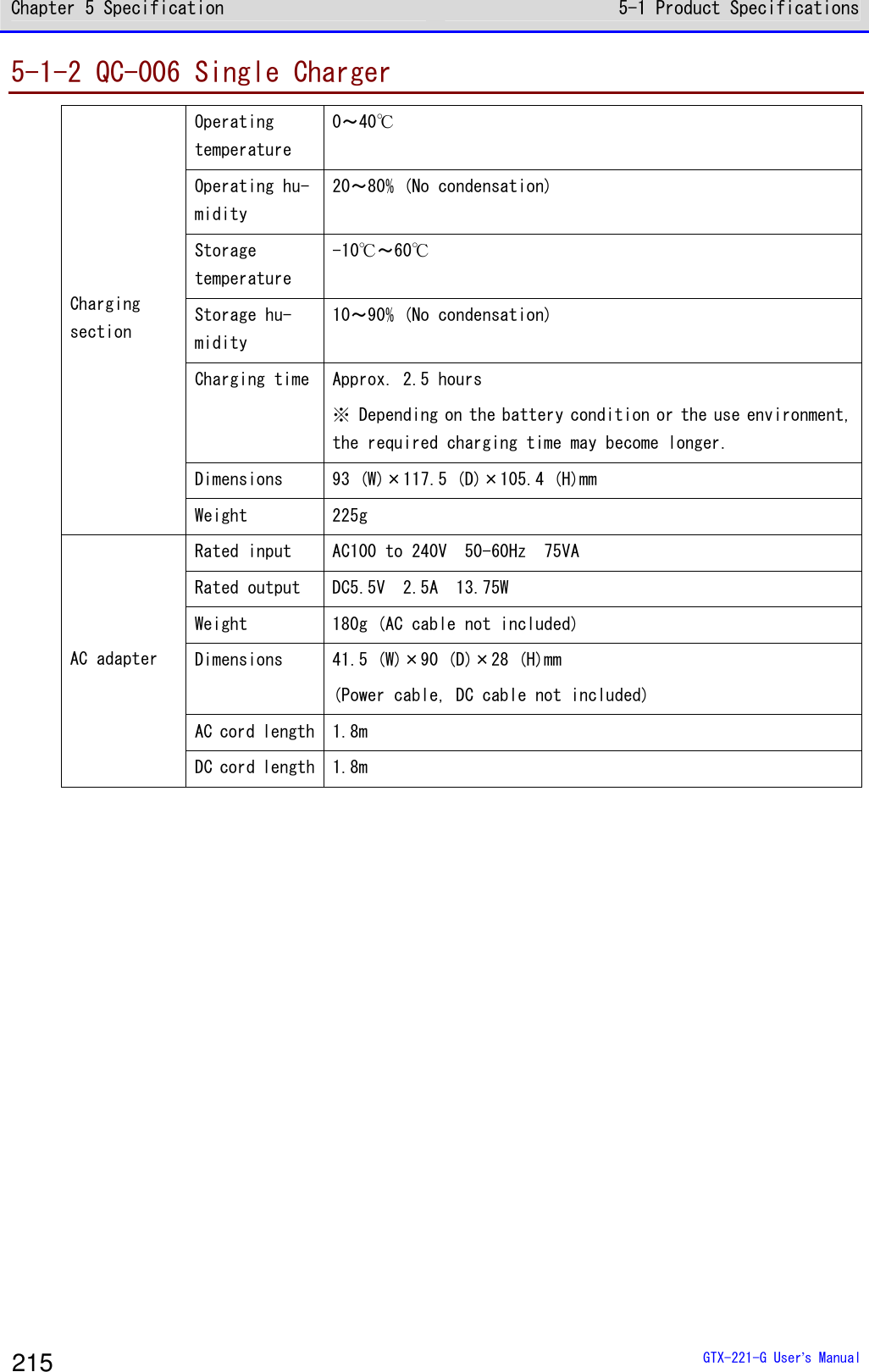
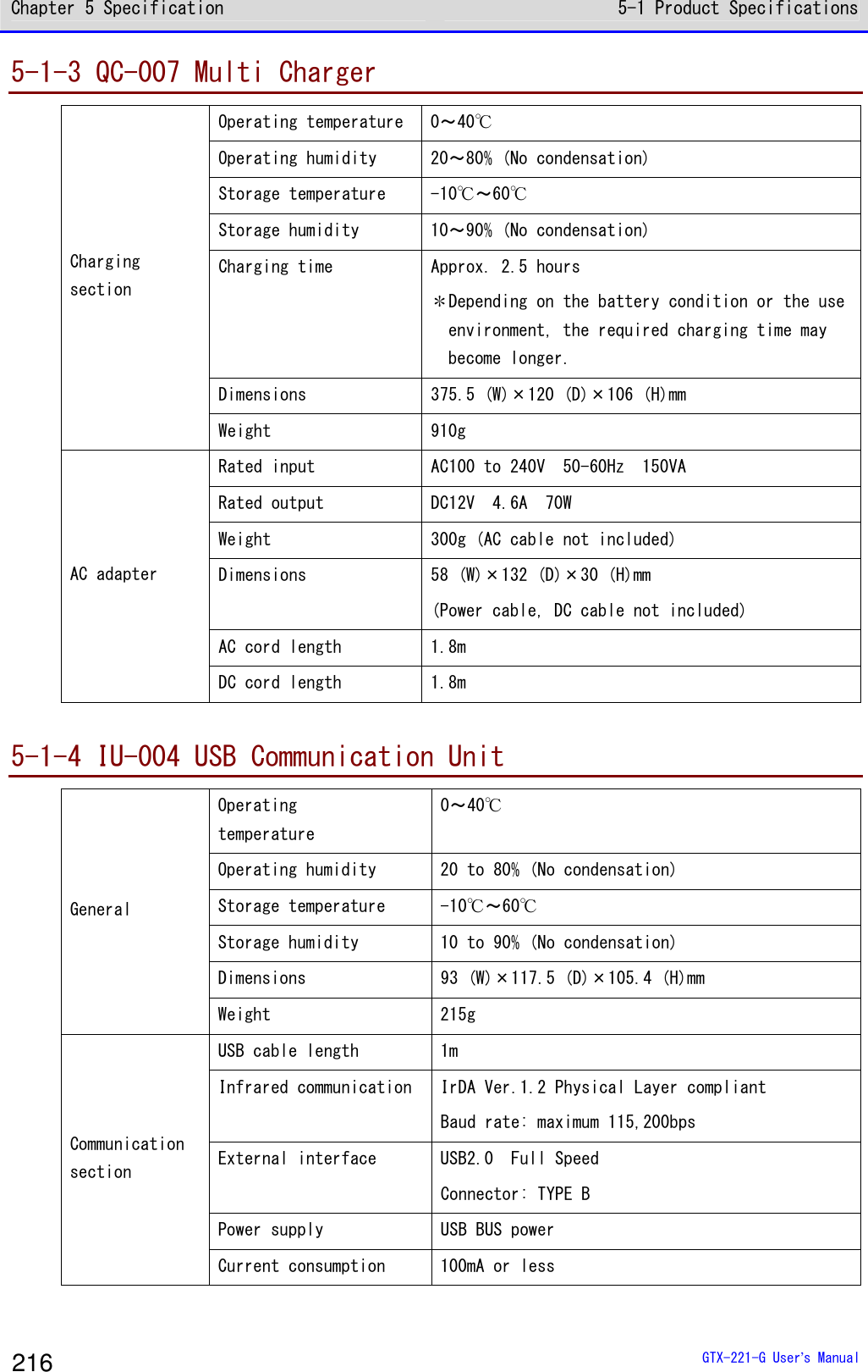

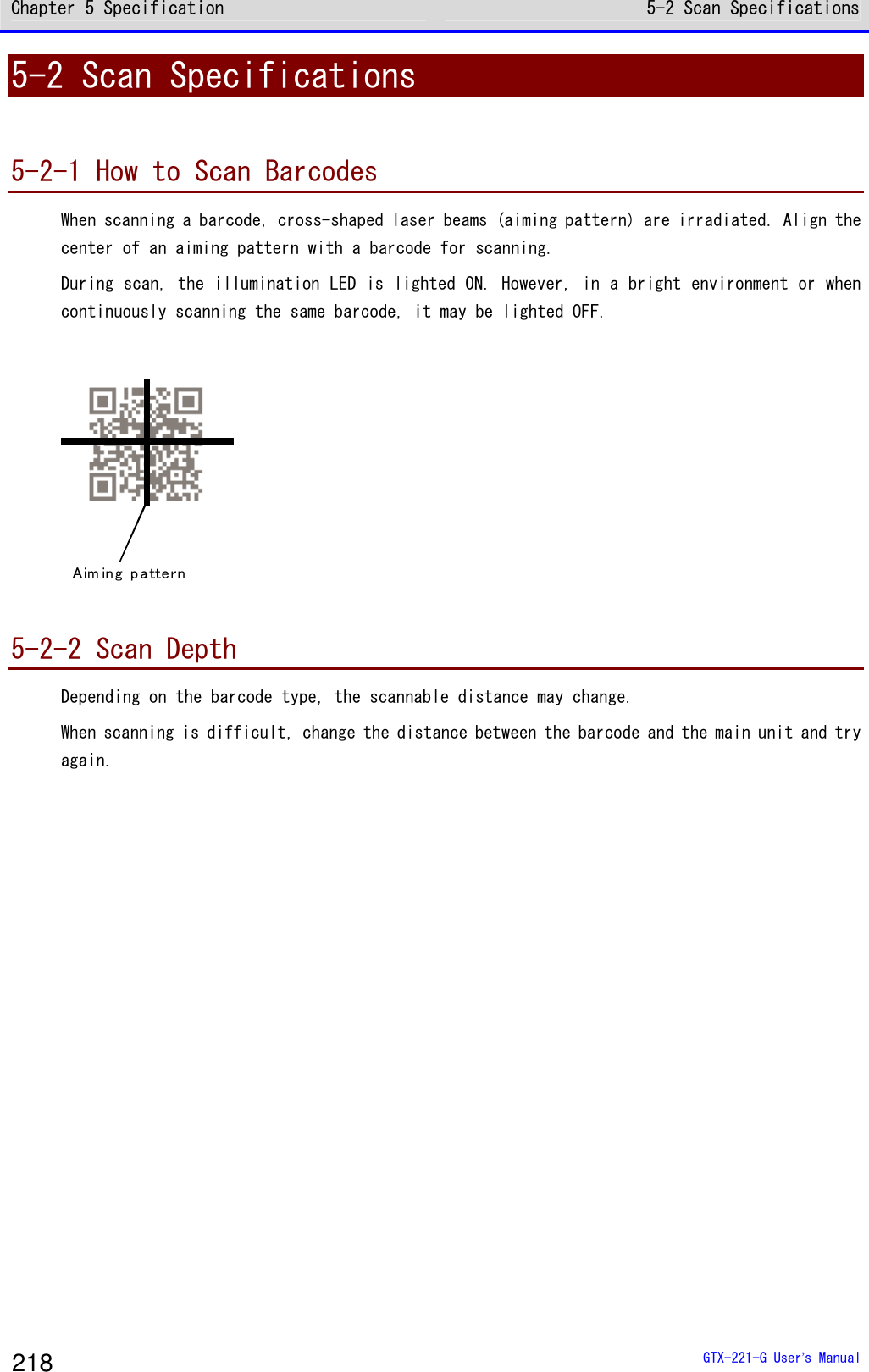
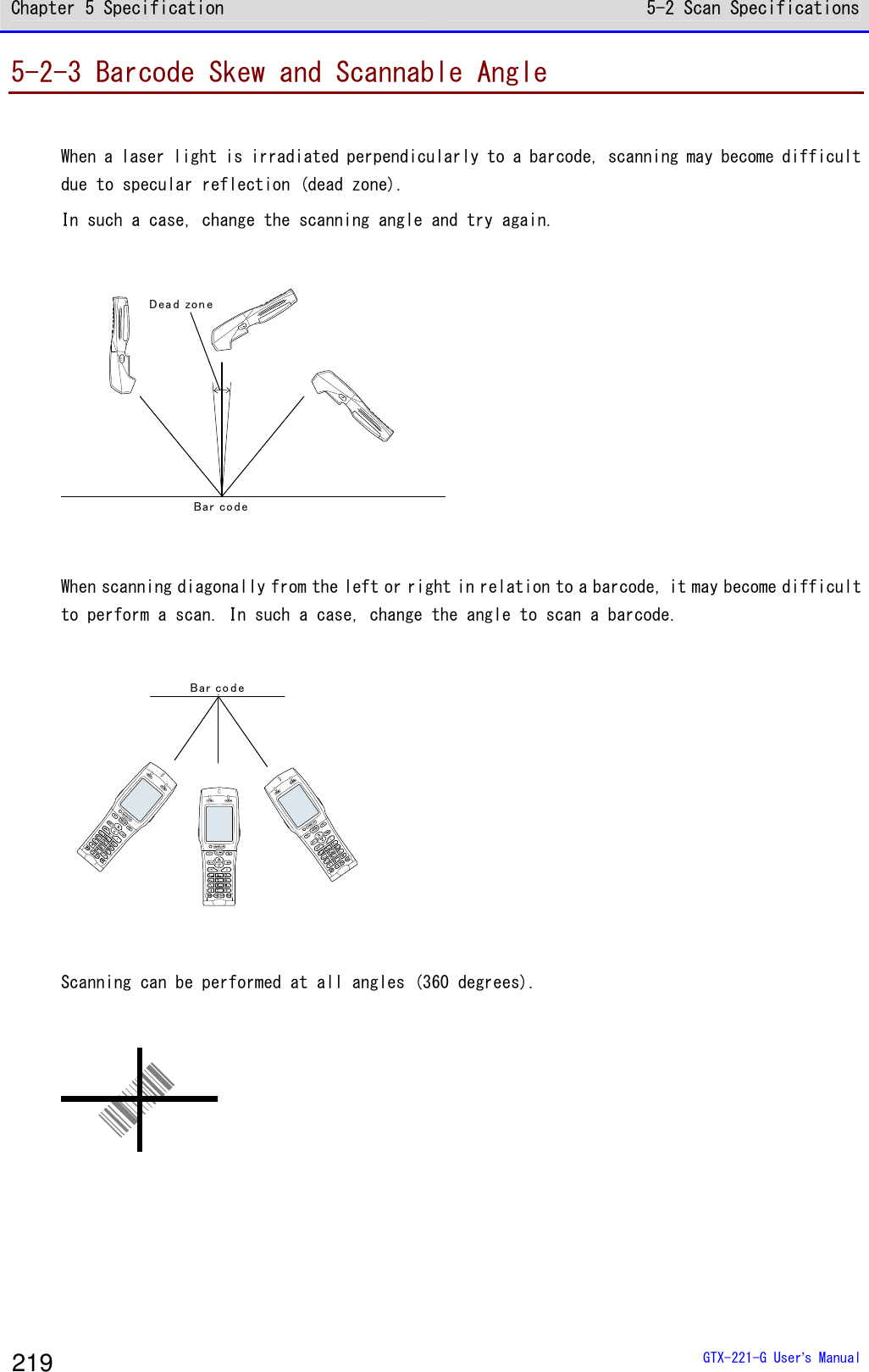
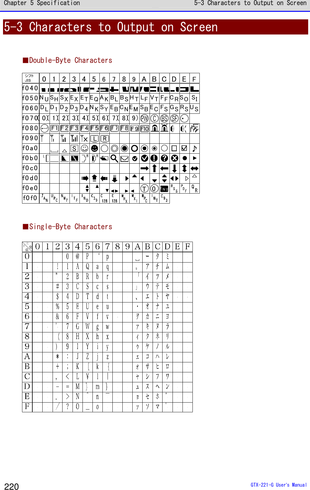

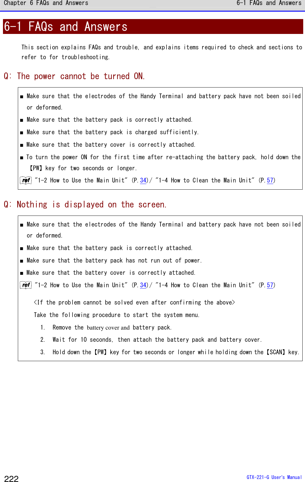
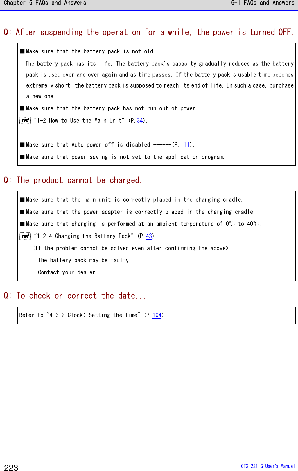
![Chapter 6 FAQs and Answers 6-1 FAQs and Answers GTX-221-G User’s Manual 224 Q: The system menu does not start. ■ To forcibly start the system menu, press the【PW】key while holding down the【SCAN】key. rrrreeeeffff "4-1-2 Starting the System Menu" (P.94) ■ If you want the system menu to always start, Select as[1: System]→[1: Auto execute] on the system menu, and select the [System Menu] radio button. rrrreeeeffff "4-3-1 Auto execute: Automatically Executing an Application Program" (P.103) Q: To change the application program starting up when the power is turned ON... ■ Select as [1: System]→[1: Auto execute] on the system menu, select the desired application program's radio button. rrrreeeeffff "4-3-1 Auto execute: Automatically Executing an Application Program" (P.103) Q: To start another application program... ■ Select as [5: File]→[1: Application], and then select [Execute] on the submenu. rrrreeeeffff "4-7 File: Executing, Uploading, and Deleting Files"-"■Execute: Execute an Application Program" (P.156) Q: A barcode cannot be scanned well. ■ Make sure that scanning is performed on the barcode appropriate for the settings of the application program. Depending on the settings of the application program, it is prohibited to scan specific types of barcodes. ■ Make sure that specular reflection does not occur. Make sure that the barcode's surface is not covered in vinyl or laminated ⇒ even if the scanning angle is not an angle at which specular reflection occurs, scanning may become difficult.Change the scanning angle and try again. ■ Make sure to scan the barcode correctly. There are specifications for the resolution and the scan distance; perform a scan in the distance range that meets the minimum widths of barcode bars and spaces. ■ Make sure that the scan distance is correct. (Refer to "5-2 Scan Specifications" (P.218).) ■ Make sure that the quality of the barcode label is good. ・Otherwise, scanning may not be performed correctly. In any of the following cases, make](https://usermanual.wiki/Welcat/GTX221G/User-Guide-1799364-Page-225.png)
![Chapter 6 FAQs and Answers 6-1 FAQs and Answers GTX-221-G User’s Manual 225 the quality of the barcode label better: ①Faintly printed barcode (as if printed by a dot impact printer or on a carbon copy slip) ②Barcode that is soiled or has missing bars ③Barcode with the widths of its bars/spaces being too narrow for the resolution of this product to handle ④Barcode without left and right blank spaces (quiet zones) (characters or lines exist to the left and right of the barcode) ⑤Barcode with irregularities in bar and space widths due to smearing or fading ⑥Warped or wrinkled label ・Change the decoding level setting and try again. For details on the decoding level setting, refer to "4-9-1 Barcode: Configuring the Barcode Scanner"-"■Decoding level (P.164). ■ Make sure that there is no problem with laser lights. ・If dirt or dust adheres to the scan window, it may become impossible to scan correctly. In such a case, wipe the filter at the scan window clean with a dry soft cloth. Q: To check the drive's free space... Select as [8: Manage]→[4: Drive] to check the free space. rrrreeeeffff "4-10-4 Drive: Displaying Drive Information" (P.195) Q: WLAN communication does not work. ■ Make sure that the access point is connected to the Ethernet LAN. Depending on the access point, WLAN communication does not operate if the LAN cable is disconnected or a link is not established. ■ Make sure that the SSID setting matches the access point.----(refer to P.114.) Match the SSID to the access point. If "ANY" (blank) is set for the SSID in the Handy Terminal, connection may not be possible due to the access point's functionality. Refer to the manual for the access point. ■ Make sure that the authentication settings are correct----(refer to P. 116). Match the authentication method to the access point. For "Shared", check the WEP settings. ■ Make sure that the WEP settings are correct. Make sure that the WEP method is correct (disable, 40bit,128bit). Make sure that the WEP TxKey_ID matches the WEP key (refer to P.116). ■ Make sure that there is no access point for which the same channel or an interfering channel is set. When a non-interfering channel is set, a maximum of four access points can be used in one area. ■ Make sure that no radio signal is generated that may cause trouble. Check that there is no device causing trouble such as a WEB camera, radio house-phone system,](https://usermanual.wiki/Welcat/GTX221G/User-Guide-1799364-Page-226.png)
![Chapter 6 FAQs and Answers 6-1 FAQs and Answers GTX-221-G User’s Manual 226 microwave oven, and another WLAN communication. In addition, PCs may generate noise. Keep PCs 1m or more away from the access point and the Handy Terminal. ■ Make sure that there is no problem with the TCP/IP settings such as IP address----(refer to P.131). Check connection to the PC by using the ping command. ■ DHCP fails. Network Management Tool is not running, or general DHCP is used that does not specify a particular port number. Caution Network Management Tool uses its own DHCP port number (8067). For that reason, the port number in the Handy Terminal should match the above. Q: Bluetooth communication does not work. ■ Make sure that the remote device to connect to is running. ■ Make sure that the remote device to connect to is set as the default device. Set the above by selecting as [7: Device]→[3: Bluetooth]→[2: Remote device]. ■ Make sure that the main unit has the same security settings as the remote device to connect to. rrrreeeeffff "4-9-3 Bluetooth: Registering and Setting the Bluetooth Device" (P.169) ■ Make sure that communication software such as BluePorter is running correctly. Q: The BluePorter-V COM port does not open. ■ Check if you use our application program called WL7-KEY in the PC with BluePorter-V embedded in it. If the version of WL7-KEY is Ver1.02 or earlier, the COM port is occupied and cannot be opened. In such a case, contact your dealer. Q: Infrared communication (IrDA) does not work. ■ Make sure that the USB cable is connected securely. ■ Make sure that the USB driver software for the USB communication unit (IU-004/004C) is installed in the PC to connect to. ■ Make sure that the transfer utility BluePorter-V is installed in the PC to connect to. ■ Make sure that the BluePorter-V icon is displayed in the notification area at the far right of the Windows task bar on the screen. Otherwise, even if BluePorter-V is installed, it is](https://usermanual.wiki/Welcat/GTX221G/User-Guide-1799364-Page-227.png)
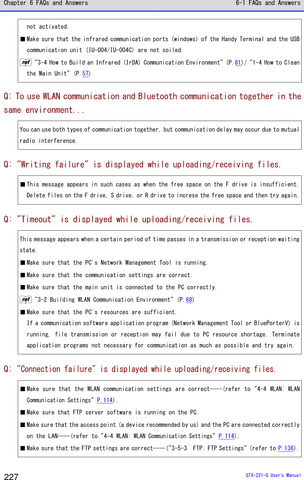
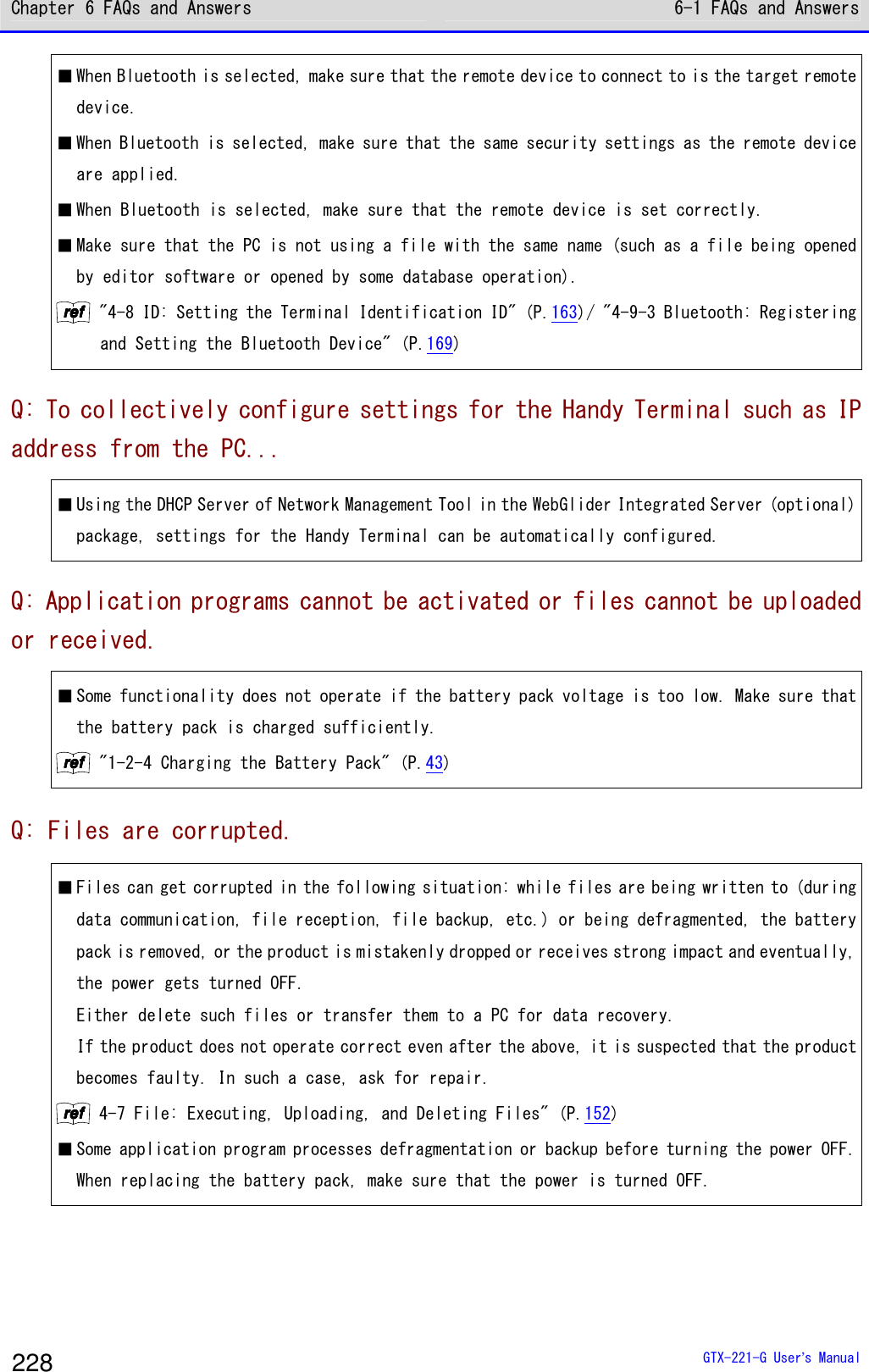
![Chapter 6 FAQs and Answers 6-1 FAQs and Answers GTX-221-G User’s Manual 229 Q: The system settings of the Handy Terminal are initialized. ■ Since the initial settings are stored in the registry file, if file corruption as above occurs, initialization may be performed. Q: When the power is turned ON, the message "SDrive has been initialized." is displayed. ■ During operation, if the battery pack or battery is removed or if the power is turned OFF due to drop impact, etc., normal termination will not be performed and data on the S drive will not be backed up. ■ The same message appears when the product is powered ON for the first time after purchase. Q: When the power is turned ON, the system menu starts up. ■ Make sure that the application program name (******. OUT) is selected after selecting as [1:System]→[1:Auto execute]on the system menu. ・Otherwise, the application program will not be automatically executed. Q: When "System error" is displayed, a key is pressed. Then, the power is turned OFF. ■ This message appears when the system program fails to identify the causes of errors. This problem occurs due to hardware, system program, or application program trouble or due to external factors such as strong static electricity. When the system error message appears, press the【PW】key, and the power is turned OFF. The next time the product is started, self recovery is performed as much as possible. Turn the power ON again. Q: The microSD becomes inaccessible. ■ The Handy Terminal does not support the SDHC standard. Use microDS cards proved operable. For microSD cards proven operable, please contact your dealer.](https://usermanual.wiki/Welcat/GTX221G/User-Guide-1799364-Page-230.png)