Welcat GTX221G Wireless 2D-code Handy Terminal User Manual
Welcat, Inc. Wireless 2D-code Handy Terminal
Welcat >
User Manual
Wireless Two-dimentional Handy Terminal
GTX-221-G
User's Manual

Trademarks
GTX-221-G User’s Manual
1
Trademarks
・ Microsoft and Windows are either registered trademarks or trademarks of Microsoft Corporation in the
United States and other countries.
・ Bluetooth is a registered trademark of Bluetooth SIG, Inc. and licensed to and used by Welcat Inc.
・ The bitmap fonts developed by Ricoh Company, Ltd. are installed in the Handy Terminal.
・ The file system "Fugue" developed by Kyoto Software Research, Inc. is installed in the Handy Terminal.
Fugue ©1999-2012 Kyoto Software Research, Inc. All rights reserved.
・ Welcat Inc. owns the copyright to this manual.
・ No part of this manual may be used or reproduced without the prior consent of Welcat Inc.
・ Product names and company names indicated in this manual are registered trademarks or trademarks of their
respective owners.
For Safe and Correct Use
GTX-221-G User’s Manual
2
For Safe and Correct Use
Thank you for purchasing our product.
Before using the Handy Terminal, read this user's manual thoroughly for proper use and maintenance of the
product. Check the product's specifications, functions, and details, and when using the product, carefully
read instructions marked on the product as well as this manual so that you can properly use the Handy Terminal
to avoid any accident. Note that it is also important to perform periodical inspection and maintenance
on the product. The following symbols classify and explain the levels of injury and damage that could be
caused if using the Handy Terminal improperly by disregarding the safety instructions indicated by the
symbols. The symbols are classified by danger level.
Danger
Indicates an imminently hazardous situation. Improper handling by disregarding this symbol could result
in death or serious injury.
Warning
Indicates a potentially hazardous situation. Improper handling by disregarding this symbol could result
in death or serious injury.
Caution
Indicates a potentially hazardous situation. Improper handling by disregarding this symbol may result in
injury or physical damage only.
The following symbols classify and explain the safety instructions you must observe:
This symbol indicates Prohibited Action. The specific details of
prohibited action are indicated in a figure with this symbol.
This symbol indicates Mandatory Action. The specific details of
mandatory action are indicated in a figure with this symbol.
This symbol indicates Alert. The specific details of alert are
indicated in a figure with this symbol.
To prevent injury to the user and others as well as property damage, observe the precautions described
in the subsequent sections.
For Safe and Correct Use
GTX-221-G User’s Manual
3
Required Precautions
To use the Handy Terminal, strictly observe the safety instructions (danger, warning, and alert) recom
mended
by the manufacturers of the PC and peripherals you are using.
Common to GTX-221-G Main Unit and Battery Pack (BP-004)
Danger
Be sure to use the specified periph
erals.
・Battery pack (BP-004)
・Single charger (QC-006)
・Multi charger (QC-007)
・USB communication unit (IU-004)
・USB communication / charging unit
(IU-004C)
Do not use, leave, or charge the product
in a location where the prod
uct becomes hot
(near fire or a space heater, or under a
hot sun) or where a flammable gas may be
generated.
Otherwise, there is a risk of battery leakage,
overheating, explosion, or fire, or the device
may become faulty.
Do not put the product into a microwave
oven or high-pressure container.
Otherwise, there is a risk of battery leakage,
overheating, explosion, or fire, or the device
may become faulty.
Do not put the product into fire or heat
the product.
Otherwise, there is a risk of battery leakage,
overheating, explosion, or fire, or the device
may become faulty.
Do not direct a laser beam toward someone's
eyes.
If laser light gets in the eyes, there is a risk
of damage to eyesight
(See "Laser Safety Standard" (P.10)).
Do not short-circuit or solder a ter
minal
such as the battery pack ter
minal and the
main unit's terminal for battery pack or
charging.
Otherwise, there is a
risk of battery leakage,
overheating, explosion, or fire, or the device
may become faulty.
Do not charge the battery pack with its
plus and minus ends reversed.
Oth
erwise, there is a risk of battery leakage,
overheating, explosion, or fire, or the device
may become faulty.
Do not get the product wet or im
merse it
in water or sea water.
Otherwise, there is a risk of battery leakage,
overheating, explosion, or fire, or the device
may become faulty.
For Safe and Correct Use
GTX-221-G User’s Manual
4
Warning
While charging the battery pack, if
charging does not become complete even
after the specified charging time, stop
charging.
Otherwise, there is a risk of battery leakage,
overheating, explosion, or fire, or the de
vice
may become faulty.
Avoid any strong shock or impact by
dropping or throwing the product.
Otherwise, there is a risk of battery leakage,
overheating, explosion, o
r fire, or the device
may become faulty.
When you detect heat, smoke, or abnormal
smell, turn the power off and remove the
battery pack.
If you continue to use the product as-
is, there
is a risk of overheating or fire. And the
battery pack may leak or explode.
Do not disassemble or modify the product.
Otherwise, there is a risk of such an acci
dent
as injury, electrical shock, and fire, or
the
device may become faulty
. Ask the retail shop
where you purchased the product for inspec-
tion
and adjustment.
Should any problem occur due to modifi
cation,
we will not take any responsibility.
Prevent any part of the body (fingers,
hand, etc.) from touching a terminal such
as the battery pack terminal and the main
unit's terminal for battery pack or
charging.
Otherwise, there is a risk of elec-trical
shock, injury, or the device may become faulty.
Keep the product away from any chemicals.
Do not use or store the product in a
location
where chemicals may come in contact or near
chemicals.
Otherwise, there is a risk of such
an accident as electrical shock and fire, or
the
device may become faulty.
Use the specified battery charger to
charge the battery pack.
Otherwise, the battery pack could overheat,
explode, or catch fire.
For Safe and Correct Use
GTX-221-G User’s Manual
5
Caution
Do not use or store the product in a location where the product becomes hot or in a humid or dusty
place.
Avoid using or storing the product in a location where the product becomes hot
such as near fire or in direct
sunlight.
Otherwise, an accident such as fire may occur; the product's chassis may be deformed; or the device
may become faulty. In addition, avoid using or storing the product in a humid or dusty place. Otherwise, an accide
nt
such as electrical shock and fire may occur, or the device may become faulty.
Do not put the product in an unstable
place.
Otherwise, the product could drop or fall down
and cause injury or the device may become
faulty.
Keep the product out of reach of small
children.
Otherwise, there is a risk of injury.
The Handy Terminal i
s intended to be used for general purposes such as office use and industrial use.
It is not assumed to be used for purposes requiring high-level safety as follows:
・Control and management of land, sea, and air transportation and traffic; control and manage
ment
of nuclear facilities; and control and management of life-support systems.
It should be noted that Welcat Inc. will not take any responsibility for damage caused by use for the pur
poses
mentioned above that involve serious danger to life, the human body, and the environment.
For Safe and Correct Use
GTX-221-G User’s Manual
6
GTX-221-G Main Unit
Warning
Be sure to prevent the hand strap from
being caught while carrying the product
.
Be very careful with the hand strap. If the hand
strap gets caught, injury or an acci
dent may
occur.
Do not use the Handy Terminal near
electronic equipment requiring
high-
accuracy control or handling feeble
signals.
Otherwise, the product could affect elec-
tronic equipment (medical electronic
equipment, fire alarms, auto
matic doors, and
other automatically-controlled equipment)
and cause its malfunction.
Do not put a foreign object into the main unit.
If a foreign object or liquid gets into the main unit, stop using the main unit and contact the retail shop where
you purchased it. If you continue to use the main unit as-
is, there is a risk of such an accident as electrical
shock and fire, or the device may become faulty.
Caution
Keep the product as far away as possible
from equipment gener
ating noise such as a
PC, fluorescent lamp, and microwave ov
en.
Otherwise, communication could not be
performed correctly due to noise.
Be sure to hold the product in your hand
when using.
If operating the product placed on the floor,
on the desk, or in the charger cradle, there is
a risk of malfunction or
the device may become
faulty.
Avoid any strong shock or impact.
Do not drop, throw, or hit the product.
Otherwise, there is a risk of the device
may
become faulty.
Do not immerse the product in water or
splash water over the product.
The Handy Terminal is not protected against
immersion in water or water splash
. Water could get
inside the product and cause such an accident as
electrical shock and fire, or
the device may become
faulty.
Do not use or store the product in a
location where strong magnetic fields
could be gen
erated such as near a magnet,
buzzer, speakers, CRT, and RFID antenna.
Otherwise, the product could malfunction or
fail.
For Safe and Correct Use
GTX-221-G User’s Manual
7
US/Canada Regulations
Note:
This equipment has been tested and found to comply with the limits for a Class B digital device, ursuant to part 15 of the
FCC Rules. These limits are designed to provide reasonable protection against harmful interference in a residential installation.
This equipment generates,uses and can radiate radio frequency energy and, if not installed and used in accordance with the
instructions, may cause harmful interference to radio communications. However, there is no guarantee that interference will
not occur in a particular installation. If this equipment does cause harmful interference to radio or television reception,
which can be determined by turning the equipment off and on, the user is encouraged to try to correct the interference by
one or more of the following measures:
—Reorient or relocate the receiving antenna.
—Increase the separation between the equipment and receiver.
—Connect the equipment into an outlet on a circuit different from that to which the receiver is connected.
—Consult the dealer or an experienced radio/TV technician for help.
Changes or modifications not expressly approved by the party responsible for compliance could void the user’
s authority to operate the equipment.
This device complies with Part 15 of FCC Rules and Industry Canada licence-exempt RSS standard(s). Operation is subject
to the following two conditions:
(1) this device may not cause interference, and
(2) this device must accept any interference, including interference that may cause undesired operation of this device.
-----------------------------------------------------------------------------------------------------
Le pr
é
sent appareil est conforme aux la partie 15 des r
è
gles de la FCC et CNR d'Industrie Canada applicables aux appareils
radio exempts de licence. L'exploitation est autoris
é
e aux deux conditions suivantes :
(1) l'appareil ne doit pas produire de brouillage, et
(2) l'utilisateur de l'appareil doit accepter tout brouillage radio
é
lectrique subi, m
ê
me si le brouillage est susceptible
d'en compromettre le fonctionnement.

For Safe and Correct Use
GTX-221-G User’s Manual
8
RF Exposure Compliance
The available scientific evidence does not show that any health problems are associated with using low power wireless
devices. There is no proof, however, that these low power wireless devices are absolutely safe. Low power Wireless
devices emit low levels of radio frequency energy (RF) in the microwave range while being used. Whereas high levels
of RF can produce health effects (by heating tissue), exposure of low-level RF that does not produce heating effects
causes no known adverse health effects. Many studies of low-level RF exposures have not found any biological effects.
Some studies have suggested that some biological effects might occur, but such findings have not been confirmed by
additional research. [Wireless 2D-code Handy Terminal (GTX-221-G)] has been tested and found to comply with FCC/IC
radiation exposure limits set forth for an uncontrolled environment and meets the FCC radio frequency (RF) Exposure
Guidelines in Supplement C to OET65 and RSS-102 of the IC radio frequency (RF) Exposure rules.
Les connaissances scientifiques dont nous disposons n’ont mis en
é
vidence aucun probl
è
me de sant
é
associ
é
à
l’
usage des appareils sans fil
à
faible puissance. Nous ne sommes cependant pas en mesure de prouver que ces appareils
sans fil
à
faible puissance sont enti
è
rement sans danger. Les appareils sans fil
à
faible puissance
é
mettent une
é
nergie
radio
é
lectrique (RF) tr
è
s faible dans le spectre des micro-ondes lorsqu’ils sont utilis
é
s. Alors qu’une dose
é
lev
é
e
de RF peut avoir des effets sur la sant
é
(en chauffant les tissus), l’exposition
à
de faibles RF qui ne produisent
pas de chaleur n’a pas de mauvais effets connus sur la sant
é
. De nombreuses
é
tudes ont
é
t
é
men
é
es sur les expositions
aux RF faibles et n’ont d
é
couvert aucun effet biologique. Certaines
é
tudes ont sugg
é
r
é
qu’il pouvait y avoir certains
effets biologiques, mais ces r
é
sultats n’ont pas
é
t
é
confirm
é
s par des recherches suppl
é
mentaires. [Wireless 2D-code
Handy Terminal (GTX-221-G)] a
é
t
é
test
é
et jug
é
conforme aux limites d’exposition aux rayonnements
é
nonc
é
es pour
un environnement non contr
ô
l
é
et respecte les r
è
gles les radio
é
lectriques (RF) de la FCC lignes directrices d'exposition
dans le Suppl
é
ment C
à
OET65 et d’exposition aux fr
é
quences radio
é
lectriques (RF) CNR-102 de l’IC.
For Safe and Correct Use
GTX-221-G User’s Manual
9
Battery Pack (BP-004)
Danger
Should the battery pack leak and fluid from the battery pack come in contact wi
th your skin or clothing,
immediately wash it off with clean water. In addition, should fluid from the battery pack get in your
eyes, do not rub them. Immediately flush your eyes with clean water and consult a doctor.
Otherwise, there is a risk of blindness or other injury.
Do not put the batty pack into fire or heat
the product.
Otherwise, there is a risk of battery leakage,
overheating, explosion, or fire.
Do not get the battery pack wet or immerse
it in water or sea water.
Otherwise, there is a risk of battery leakage,
overheating, explosion, or fire.
Don't put a nail on, hit with a hammer, or
stomp on the battery pack.
Otherwise, there is a risk of battery leakage,
overheating, explosion, or fire.
Warning
Do not use the battery pack if it leaks, or gets deformed or discolored.
If you continue to use the battery pack as-is, it could overheat, e
xplode, catch fire, or leak. And keep the
battery pack away from fire. Otherwise, leaked electrolyte could catch fire.
For Safe and Correct Use
GTX-221-G User’s Manual
10
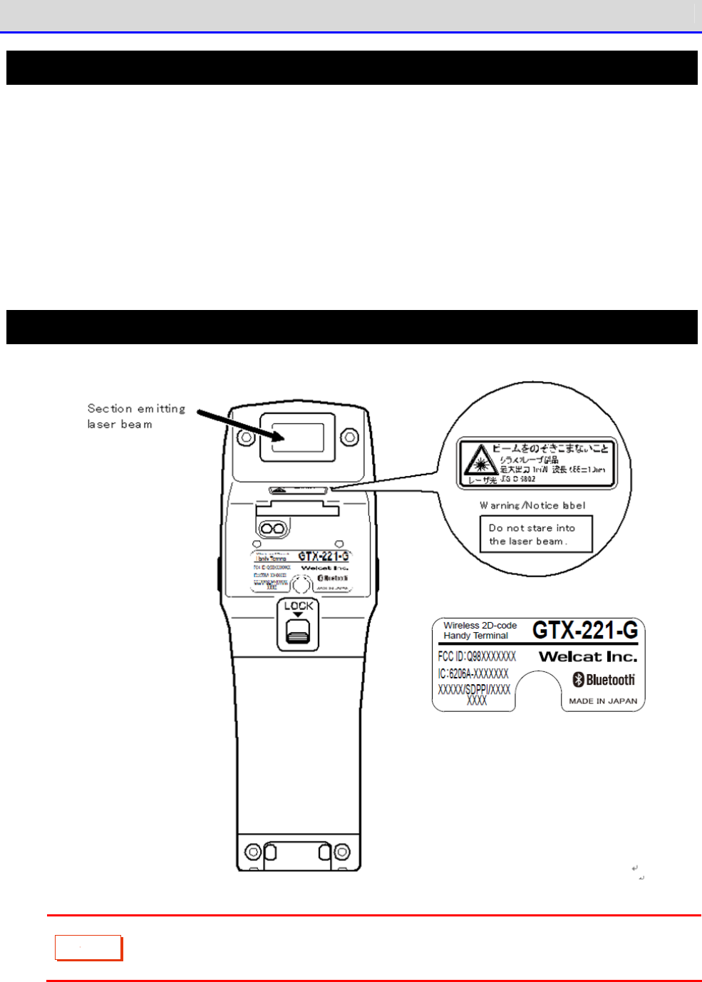
Laser Safety Standard
The Handy Terminal complies with the JIS C 6802 laser product safety standard.
Laser class: Class 2
Maximum output: 1mW
Wavelength: 655±10nm
Your aversion response such as eye blinking can protect your eyes against lasers in Class 2. However,
do not stare at a laser beam or get a laser beam in your eyes.
Laser-Related Warning Label
C
a
u
t
i
o
n
Be sure to observe instructions in the user's manual and don't disassemble the
product. Otherwise, there is a risk of exposure to dangerous laser emitting.

For Safe and Correct Use
GTX-221-G User’s Manual
11
LCD Screen
Depending on the product, red, blue, or green bright dots may remain on the screen or small dark dots
may appear. In addition, when used in a low-temperature environment, the screen display looks a little
slow to react. All these are irregularities due to the characteristics of the LCD and are not defects.
Precautions on Radio Waves
Be sure to observe the following precautions on using the Handy Terminal:
・Do not use the Handy Terminal when a person with cardiac pacemaker is around or near medical equipment.
Otherwise, magnetic interference with medical equipment could occur and cause danger to life.
・Do not use the Handy Terminal near a microwave oven.
Otherwise, a microwave oven could generate magnetic interference with radio communication of the
Handy Terminal.
The following equipment and systems operate in the frequency band used by the Handy Terminal: industrial,
scientific, and medical equipment including microwave ovens, private-radio stations (licensed radio
stations) for mobile-unit identification used in factory production lines; specified low-power radio
stations (radio stations not requiring licenses); and amateur radio stations (radio stations requiring
licenses).
・Before using the Handy Terminal, confirm that none of the following stations operates: private-radio
stations for mobile-unit identification; specified low-power radio stations; and amateur radio
stations.
・Should the Handy Terminal cause harmful radio interference with a private radio station for mobile-unit
identification, immediately change the frequency used, or stop emitting radio waves. Then, take
measures to avoid interference such as installing partitions.
For Safe and Correct Use
GTX-221-G User’s Manual
12
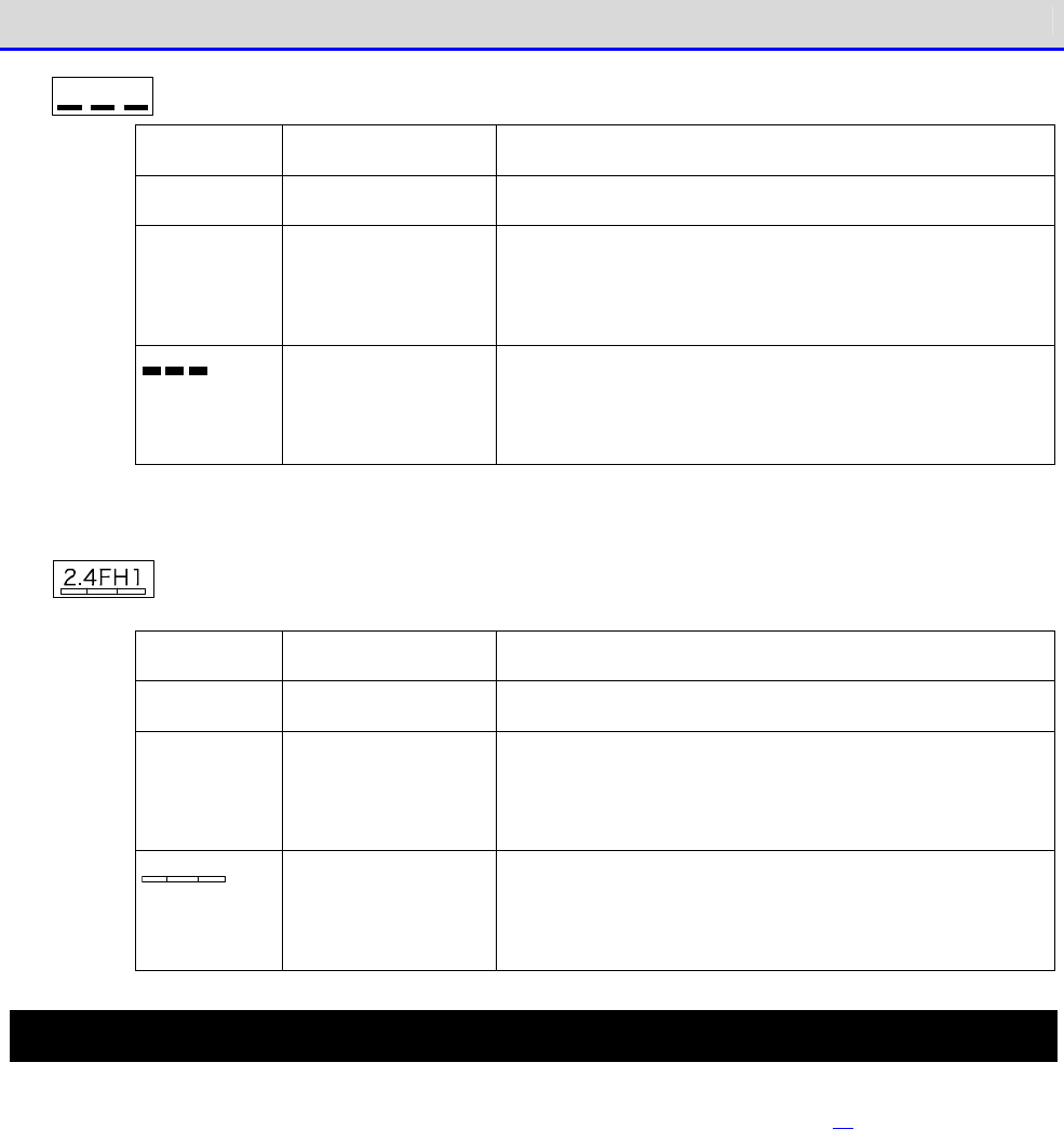
2 .4 D S/O F4
written on the product label means the following:
2.4 Frequency band used
2.4GHz band
DS/OF Modulation method DS-SS, OFDM
4 Assumed
interfering dis-
tance
40m or less
Possibility of
frequency change
Indicat
es that the whole bandwidth is used and that
it is possible to avoid the bandwidth of mobile-
unit
identification equipment.
written on the product label means the following:
2.4 Frequency band used
2.4GHz band
FH Modulation method FH-SS
1 Assumed
interfering dis-
tance
10m or less
Possibility of
frequency change
Indicates that the whole bandwidth is used and that
it is not possible to avoid the bandwidth of mo-
bile-unit identification equipment.
Notes on microSD Cards
Use microSD cards proved operable (See "1-2-3 Handling the microSD Card" (P.38)).
For details on how to handle microSD cards, see the instruction manual provided with your microSD card.

Contents
GTX-221-G User’s Manual
13
Contents
Trademarks .................................................................... 1
For Safe and Correct Use ...................................................... 2
Required Precautions ................................................................... 3
Laser Safety Standard ................................................................. 10
Laser-Related Warning Label ........................................................... 10
LCD Screen ............................................................................ 11
Precautions on Radio Waves ............................................................ 11
Notes on microSD Cards ................................................................ 12
Contents ..................................................................... 13
Summary of This Manual ....................................................... 19
■Composition of This Manual ............................................................ 19
■Notes on Symbols, Terms, and Manual Conventions ....................................... 20
System Architecture .......................................................... 21
■Product Configuration ................................................................. 21
■WLAN Communication System Configuration ............................................... 22
■Bluetooth Communication System Configuration .......................................... 23
■Infrared Communication (IrDA) System Configuration..................................... 24
Chaper 1 Hardware
1-1 About the Scanner ........................................................ 26
1-1-1 Confirm the Supplied Items ...................................................... 26
1-1-2 Optional Items .................................................................. 27
1-1-3 Name and Function of Each Unit .................................................. 29
■LED indicator ......................................................................... 31
■Names of Operation Keys ............................................................... 32
■LCD Screen Status Bar ................................................................. 33
1-2 How to Use the Scanner ................................................... 34
1-2-1 Attaching the Hand Strap ........................................................ 34
1-2-2 Handling the Battery Pack ....................................................... 35
■Attaching the Battery Pack ............................................................ 35
■Detaching the Battery Pack ............................................................ 37
1-2-3 Handling the microSD Card ....................................................... 38
■Tested microSD Card ................................................................... 38
■Installing the microSD Card ........................................................... 39
■Detaching the microSD Card ............................................................ 41
1-2-4 Charging the Battery Pack ....................................................... 43
■Charging One Unit ..................................................................... 44
■Charging Multiple Units ............................................................... 46

Contents
GTX-221-G User’s Manual
14
1-2-5 Remaining Charge Level Display and Alarm for the Battery Pack ................... 48
■Remaining Charge Level Display for the Battery Pack.................................... 48
■Charging the Backup Battery ........................................................... 49
1-2-6 Memory Backup ................................................................... 50
■Memory Backup ......................................................................... 50
■Charging the Backup Battery ........................................................... 51
1-2-7 Long-term Storage ............................................................... 52
■Long-term Storage of the Scanner ...................................................... 52
■Long-term Storage of the Battery Pack ................................................. 52
1-3 Basic Usage Method ....................................................... 53
1-3-1 Power ON/OFF .................................................................... 53
1-3-2 How to Read a Barcode ........................................................... 54
■Read Method ........................................................................... 54
1-3-3 Useful Features during Operation ................................................ 55
■Forcible Startup on the System Menu ................................................... 55
■Auto-dimming Setting .................................................................. 55
■Buzzer Volume Adjustment .............................................................. 55
■Resume Function (Retention of the State during Power OFF).............................. 56
■Auto Wakeup (Power ON after Preset Time) .............................................. 56
■Auto Power OFF (Automatic Power OFF) .................................................. 56
1-4 Maintenance Method ....................................................... 57
Chaper 2 Software
2-1 About Software ........................................................... 59
2-1-1 About Data ...................................................................... 59
■Drive Configuration ................................................................... 59
■About File Name ....................................................................... 60
■About File Extension .................................................................. 60
■Files Created by the System or the Application Software................................ 61
2-2 Registry ................................................................. 62
2-3 Create an Application Software ........................................... 63
■Peripheral Softwares .................................................................. 63
■Operating Environment ................................................................. 64
Chapter 3 Communication Environment Settings
3-1 Communication Type ....................................................... 66
■WLAN Communication .................................................................... 66
■Bluetooth Communication ............................................................... 67
■Infrared Communication (IrDA) ......................................................... 67

Contents
GTX-221-G User’s Manual
15
3-2 Building WLAN Communication Environment .................................. 68
3-2-1 Preparation on the PC Side ...................................................... 68
3-2-2 Preparation on the Product Side ................................................. 69
■WLAN Communication Settings by Setting Wizard ......................................... 70
■WLAN Communication Settings by the System Menu ........................................ 73
■WLAN Communication Settings by DHCP ................................................... 74
3-2-3 Downloading the Application Software by WLAN Communication ..................... 75
3-3 Building Bluetooth Communication Environment ............................ 77
3-3-1 Preparation on the PC Side ...................................................... 77
■COM Port Verification ................................................................. 77
3-3-2 Preparation on the Product Side ................................................. 78
3-3-3 Downloading the Application Software by Bluetooth Communication ................ 78
3-4 Building Infra-red Communication (IrDA) Environment ...................... 81
3-4-1 Preparation on the PC Side ...................................................... 82
3-4-2 Downloading the Application Software by Infrared Communication (IrDA) ........... 83
■Equipment Preparation ................................................................. 83
■Preparation before Use ................................................................ 83
■Transfer Utility BluePorter-V Startup ................................................. 84
■Communication Settings ................................................................ 84
■File Download ......................................................................... 86
3-5 Executing the Application Software ....................................... 88
■Selecting from the File List to Execute ............................................... 88
■Automatic Execution upon Startup ...................................................... 90
Chapter 4 System Menu
4-1 Using the System Menu .................................................... 92
4-1-1 Operation Keys .................................................................. 92
■List of Key Assignments ............................................................... 93
4-1-2 Launching the System Menu ....................................................... 94
4-1-3 When Launching the System Menu for the First Time ............................... 94
4-1-4 Using the System Menu ........................................................... 95
■Selecting Setting Items ............................................................... 95
■Entering Data Using Keys. ............................................................. 96
■Other Operations ...................................................................... 98
■Entering Data Using a Barcode ........................................................ 100
4-2 System Menu Structure ................................................... 101
4-3 System: Settings to Simplify Your Operations ............................ 103
4-3-1 Auto Execute: Automatic Execution of the Application Software ................. 104
4-3-2 Clock: Time Settings .......................................................... 105
■Current Time ......................................................................... 105

Contents
GTX-221-G User’s Manual
16
■Manual setting: Sets the Time Manually .............................................. 105
■
Server setting: Receives the time automatically from the server ......................... 106
4-3-3 Power Management: Various Settings Related to Power ............................ 107
■Resume Function: Retaining the State during Power OFF................................. 107
■Auto wakeup: Started at the Predefined Time .......................................... 109
■Auto Power OFF: Automatic Power OFF .................................................. 111
4-3-4 Password: Setting / Clearing Password .......................................... 112
■Set: Setting the Password ............................................................ 113
■Clear: Clearing the Password ......................................................... 113
4-4
WLAN: WLAN Communication Settings
......................................... 114
4-4-1 SSID: Setting SSID ............................................................. 114
4-4-2 Roaming level: Setting the Roaming Level ....................................... 115
4-4-3 Doze mode: Setting the Timeout Time ............................................ 115
4-4-4
Security: WLAN Communication Security Settings
......................................... 116
■Encryption ........................................................................... 116
■Authentication ....................................................................... 121
■Attention ............................................................................ 126
4-4-5 Advanced: Advanced Settings Related to WLAN Communication ...................... 127
4-4-6 MAC address: Displaying the MAC Address ........................................ 129
4-5 Network: Network Connection Settings .................................... 130
4-5-1 TCP/IP: TCP/IP Settings ........................................................ 131
4-5-2 DHCP: DHCP Settings ............................................................ 133
■Startup type ......................................................................... 134
■Item not to update ................................................................... 135
■Server port .......................................................................... 135
4-5-3 FTP: FTP Settings .............................................................. 136
■Server address ....................................................................... 136
■User name ............................................................................ 137
■Password ............................................................................. 137
■Advanced ............................................................................. 138
4-5-4 DNS: DNS Server Settings ....................................................... 140
■Primary .............................................................................. 140
■Secondary ............................................................................ 141
■Advanced ............................................................................. 141
4-5-5 SNMP: SNMP Setting ............................................................. 142
■Community (R/Only) ................................................................... 142
■Community (R/W) ...................................................................... 143
■Trap ................................................................................. 143
■Advanced ............................................................................. 144
4-6 Receive: Receiving Files ................................................ 146

Contents
GTX-221-G User’s Manual
17
4-6-1 Receive: Receiving Files by WLAN/Bluetooth/Infrared Communication (IrDA) ....... 146
■Receiving Files (WLAN) ............................................................... 148
■Receiving Files (Bluetooth/IrDA) ..................................................... 150
4-7 File: Executing, Uploading, and Deleting Files .......................... 152
■Execute: Execute an Application Program .............................................. 156
■Play: Play Audio Data ................................................................ 156
■View: Display Graphic Data ........................................................... 156
■Properties: Display Detailed Information of a File.................................... 157
■Upload: Upload Files to a PC or Another Terminal...................................... 158
■Delete: Delete Files ................................................................. 160
■All Checks Applied: Select All Files ................................................. 161
■All Checks Removed: Deselect All Files ............................................... 161
■Copy to the Specified Drive .......................................................... 162
4-8 ID: Setting the Terminal Identification ID
................................... 163
4-9 Device: Setting Hardware Functions ...................................... 164
4-9-1 Barcode: Configuring the Barcode Scanner ....................................... 164
■Trigger Mode ......................................................................... 165
■Version .............................................................................. 167
■Picklist Mode ........................................................................ 167
■Inverted barcode ..................................................................... 168
4-9-2 Key: Setting the Key Repeat .................................................... 168
4-9-3 Bluetooth: Registering and Setting the Bluetooth Device ........................ 169
■Local Device ......................................................................... 169
■Remote Device ........................................................................ 171
4-9-4 Setting the Display/Backlight Luminosity ....................................... 177
■Luminosity ........................................................................... 177
■Light Sensor ......................................................................... 178
4-9-5 Tone/Vibrator: Setting the Volume, LED, and the Vibrator ....................... 178
■Volume ............................................................................... 179
■Indicator Func ....................................................................... 179
■Click Sound .......................................................................... 183
4-10 Management: Setting Basic Information and Management ................... 184
4-10-1 System info: Checking the OS Version .......................................... 184
4-10-2 Format: Registry/Drive Formatting............................................... 185
4-10-3 Clone: Creating a Copy ........................................................ 187
■How to Execute Clone ................................................................. 187
■Bluetooth/IrDA ....................................................................... 188
■microSD .............................................................................. 192
4-10-4 Drive: Displaying Drive Information ........................................... 195
4-10-5 Mothball: Settings When Not Using the Product For Long ........................ 196

Contents
GTX-221-G User’s Manual
18
4-10-6 Wizard: Starting the Screen Facilitating Configuration of Communication Settings
..................................................................................... 197
4-10-7 OS Update: Updating the OS of TheHandy Terminal ............................... 198
4-11 Test: Testing Hardware Devices ......................................... 200
4-11-1 WLAN: Testing WLAN Communication .............................................. 200
■Configuration ........................................................................ 201
■WLAN/ping test ....................................................................... 202
■AP Search ............................................................................ 203
4-11-2 Bluetooth: Testing Bluetooth Communication .................................... 204
4-11-3 IrDA: Testing Infrared Communication .......................................... 205
4-11-4 Barcode ....................................................................... 206
■Barcode Option ....................................................................... 206
4-11-5 Display: Testing the LCD Screen ............................................... 207
4-11-6 Key: Testing Key Operations and Indicators .................................... 208
Chapter 5 Specification
5-1 Product Specifications .................................................. 210
5-1-1 GTX-221-G Wireless Two-Dimensional Handy Terminal .............................. 210
■Dimensions ........................................................................... 214
5-1-2 QC-006 Single Charger .......................................................... 215
5-1-3 QC-007 Multi Charger ........................................................... 216
5-1-4 IU-004 USB Communication Unit .................................................. 216
5-1-5 IU-004C USB Communication/Charging Unit ........................................ 217
5-2 Scan Specifications ..................................................... 218
5-2-1 How to Scan Barcodes ........................................................... 218
5-2-2 Scan Depth ..................................................................... 218
5-2-3 Barcode Skew and Scannable Angle ............................................... 219
5-3 Characters to Output on Screen .......................................... 220
■Double-Byte Characters ............................................................... 220
■Single-Byte Characters ............................................................... 220
Chapter 6 FAQs and Answers
6-1 FAQs and Answers ........................................................ 222
Appendix
Consumables ................................................................. 230
Appendix-1 Factory Default List ............................................. 232
Appendix-2 Sample Barcodes .................................................. 236
Appendix-3 Glossary ......................................................... 242
Summary of This Manual
GTX-221-G User’s Manual
19
Summary of This Manual
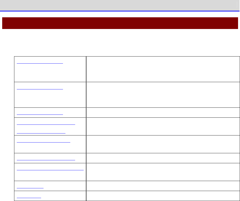
■Composition of This Manual
This manual is made up of of the following:
System Architecture Explains an overview of the system configuration of the Handy
Terminal. Read this part for a better understanding of the
product.
Chapter 1 Hardware Explains how to use each part of the Handy Terminal and how to
use the hardware such as attaching the battery pack, charging,
and reading barcodes.
Chapter 2 Software Explains the software.
Chapter 3 Communication
Environment Settings
Explains an environment for creating application software and how
to create, install, and execute application software.
Chapter 4 System Menu Explains how to operate basic functions and explains the system
menu.
Chapter 5 Specification
Product specifications list.
Chapter 6 FAQs and Answers
Explains FAQs and trouble, and explains items required to check
for troubleshooting.
Consumables Explains consumables.
Appendixes Desribes the settings before shipment and sample barcode.
Summary of This Manual
GTX-221-G User’s Manual
20
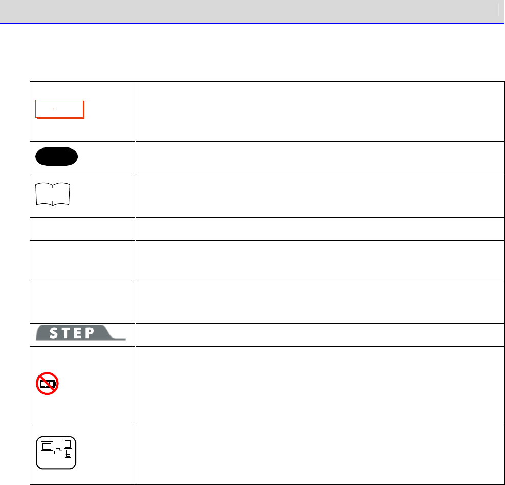
■Notes on Symbols, Terms, and Manual Conventions
In this manual, the following symbols, terms, and conventions are used:
C
a
u
t
i
o
n
Describes items to be observed by the user and precautions when operating
the product. Carefully read the desription indicated by this symbol and
be sure to observe the instructions.
Hint
Describes useful information and tips.
r
rr
re
ee
ef
ff
f
Introduces pages describing related information or other manuals.
Product/main unit Means the GTX-221-G main unit.
【 】 key
Names of keys on the control panel are described using 【 】.
Example: the 【PW】 key
[ ]
UIs displayed on screen are described using [ ].
Example: [System Menu]
Explains how to operate the system menu.
Some operation on the system menu is restricted when the battery pack level
is lower than the specified value (which depends on the operation) at the
time of execution. This symbol is used to explain how to perform operation
in such cases.
DHCP
For some operation on the system menu, the settings can be collectively
made from your PC using the DHCP client function. This symbol is used for
how to operate the DHCP client function in such cases.
System Architecture
GTX-221-G User’s Manual
21
System Architecture
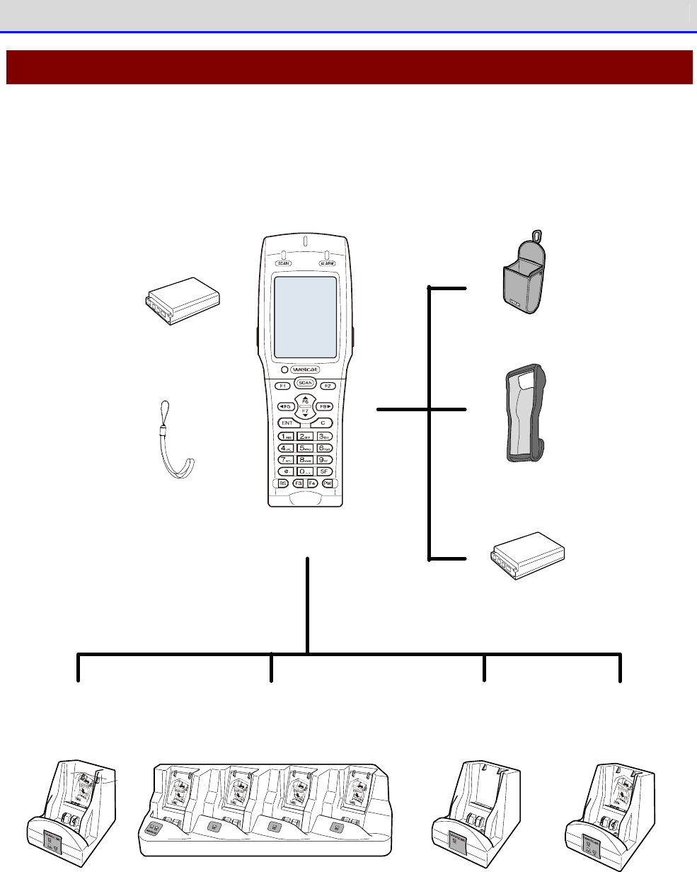
■Product Configuration
The basic product configuration for the Handy Terminal is given below. Please ensure that the
necessary accessories are available.
QC -0 0 6 QC-0 0 7 IU-0 0 4 IU-0 0 4 C
Hand strap
(su pp lied with term inal)
Battery p ack
BP-0 0 4
(sup plied with term inal)
Po rtab le ho lder
CB-0 0 1
(Optio nally availab le)
Im p act-resistant p ro tective co ver
DC -0 1 1
(Optionally availab le)
Battery p ack
BP-0 0 4
(Op tio nally availab le)
Charg e the hand y term inal
/battery p ack
(One unit)
Charg e the hand y term inal
/battery p ack
(Fou r unit)
IrDA com m unication IrDA com m unication
+
Charg e the h an d y term inal
/battery p ack
(One unit)
W ireless Two-d im en sional Hand y Term inal
XIT-2 2 0 -G
System Architecture
GTX-221-G User’s Manual
22
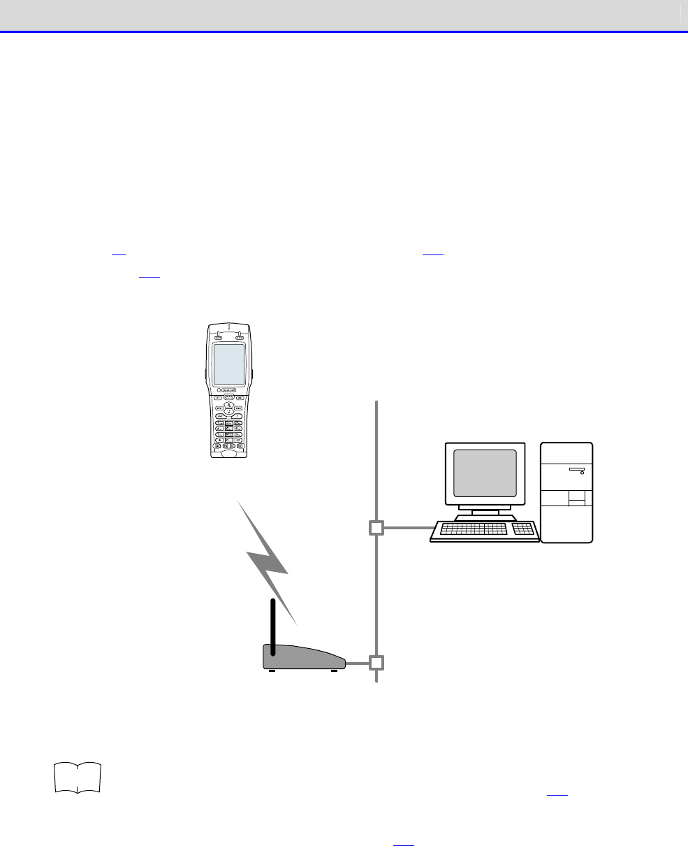
■WLAN Communication System Configuration
You can perform communication with a PC after configuring WLAN communication and TCP/IP with
the access point connected to the Ethernet LAN.
This makes it possible to download an application software created on the PC, transmit/receive
data, or configure the Handy Terminal from the PC.
This communication requires an access point, an Ethernet cable and a HUB.
For WLAN communication settings related details, see "3-2 Building WLAN Communication Environ-
ment" (P.68)"4-4
WLAN: WLAN Communication Settings
" (P.114)."4-5 Network: Network Connection
Settings" (P.130) as well as the access point manual.
W LAN
co m m unication
LAN
Access po int
*Please use our reco m m end ed p ro d ucts.
W ireless Two-dim ensio nal H and y Term inal
XIT-2 2 0 -G
PC having the following software in stalled
・ W eb Glider-X2 Ed itor packag e
(W GE-0 0 2 ): Optio nally availab le
・ W eb GliderInteg rated server
(W GS-0 0 1 ): Op tionally availab le
・ Netwo rk control too l
(Sup p lied with W GS-0 0 1)
r
rr
re
ee
ef
ff
f
·
When sending files to a PC from the Handy Terminal
"4-7 File: Executing, Uploading, and Deleting Files" (P.152)
・When receiving files from a PC to the Handy Terminal
"4-6 Receive: Receiving Files" (P.146)
System Architecture
GTX-221-G User’s Manual
23
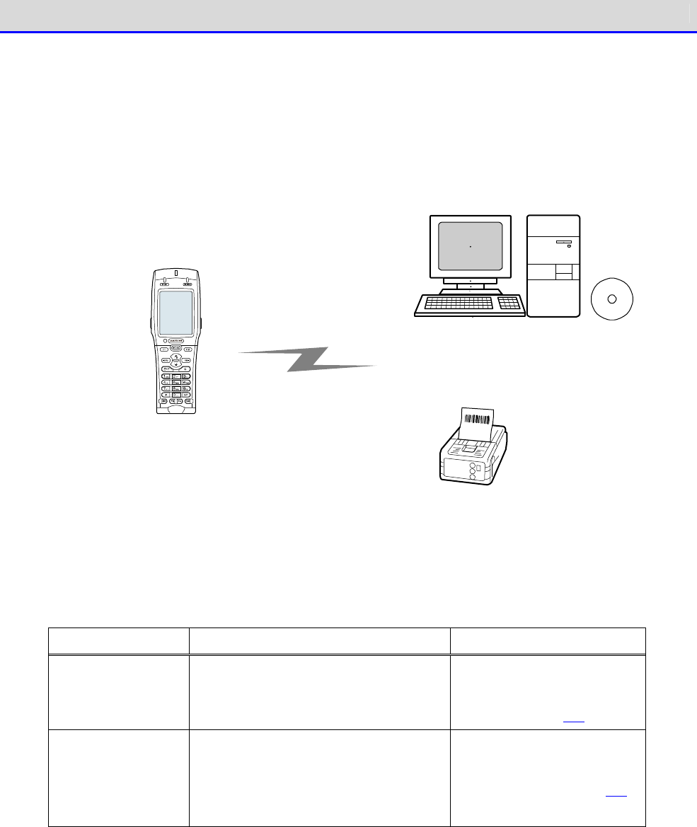
■Bluetooth Communication System Configuration
You can transfer files between the PC and the Handy Terminal by connecting a Bluetooth
communication adapter to a USB port of the PC. This communication mode requires an optional
transfer utility, the BluePorter-V Bluetooth pack (WLF
–
003
–
BT2). There are also usage methods
such as printing after sending the data to a portable printer that has Bluetooth connectivity.
Bluetoo th co m m unicatio n
Bluetoo th co m patib le d evices such
as the p ortab le p rinter and PDA
(As for the p ortab le p rinter, p lease
use our recom m end ed p roducts)
Transfer utility BluePorter-V
(Bluetoo th co m m unication ad aptor
is includ ed in the utility.)
W LF-0 0 3 -BT2 (Op tionally availab le)
W ireless Two-dim ensio nal Hand y Term inal
XIT-2 2 0 -G
Bluetooth communication requires the following settings:
Item
Description
Reference page
Terminal ID Sets the ID for identification.
Set when sending/receiving files
using BluePorter-V.
"4-8 Terminal ID: Config
ure
the ID for Terminal Iden-
tification" (P.163)
Bluetooth
Registration
You can perform settings such as
security, and registration of the
connection destination required by
Bluetooth communication.
"4-9-3 Bluetooth: Regis-
tering and Setting the
Bluetooth Device" (P.169)
System Architecture
GTX-221-G User’s Manual
24
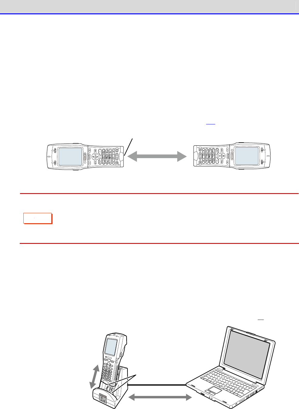
■Infrared Communication (IrDA) System Configuration
You can use infra-red (IrDA) communication between Handy Terminals, or with a PC via a USB
communication unit.
●Communication between Handy Terminals
You can perform file transfer between Handy Terminals.Communication is performed with the
infrared communication ports of two Handy Terminals aligned with each other.
Ensure that the distance between the infrared communication ports is not more than 15cm.
For details, see "●To use infrared (IrDA) communication" (P.158).
IrDA com m unication
IrDA co m m unication p ort
C
a
u
t
i
o
n
In infrared communication, communication trouble may occur the influence of
ambient light.
Be sure to prevent the light from entering the infrared communication port during
communication.
●Communication by USB Communication Unit
Files can be sent/received to/from a PC via a USB communication unit (IU-004) or USB com-
munication/charging unit (IU-004C).
This communication mode requires an optional IU-004 or IU-004C, and also the transfer utility
BluePorter-V.
For details, see "3-4 Building Infra-red Communication (IrDA) Environment" (P.81).
PC having the USB driver
and transfer utility
(BluePorter-V) installed
IrDA com m unication
between the hand y
term inal and
com m unicatio n/
charg ing unit
IrDA com m unication
port
Com m unication via the
USB cab le between the
com m u nication /
charg ing unit and PC.

Chapter
1
Hardware
Chapter 1 Hardware 1-1 About the Handy Terminal
GTX-221-G User’s Manual
26
1-1 About the Handy Terminal
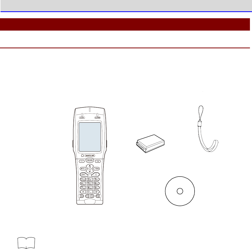
1-1-1 Confirm the Supplied Items
The following items are supplied with the Handy Terminal. Check whether all these items are
present.
If any item is missing or found to be defective, please contact your dealer.
Battery pack
BP-0 0 4
W ireless Two-dim ensio nal H and y Term inal
XIT-2 2 0 -G
Hand strap
User's M anual
CD-ROM
r
rr
re
ee
ef
ff
f
One user manual CD (this manual) is supplied with each order (one CD is included
with each order regardless of the number of units ordered).

Chapter 1 Hardware 1-1 About the Handy Terminal
GTX-221-G User’s Manual
27
1-1-2 Optional Items
The Handy Terminal has the following related accessories. Prepare them when necessary.
Product Name
Model No.
Description
Battery Pack
BP-004 Rechargeable lithium-ion battery.
Single Charger
QC-006 This charger is for charging a Handy Terminal and a
battery pack.
It can charge one Handy Terminal and one battery pack.
Multi Charger
QC-007 This charger is for charging multiple Handy Terminal
s
and battery packs.
It can charge up to four Handy Terminals and four
battery packs.
USB Communication
Unit
IU-004
This communication unit has no charging function; it
is used to connect the Handy Terminal to a PC. Com-
munication between the Handy Terminal and IU-004 is
performed via infra-red rays, and communication
between IU-004 and a PC is performed via USB.
USB Communication/
Charging Unit.
IU-004C This communication unit connects the Handy Terminal
to
a PC, and also has a charging function.Its charging
function allows charging of both one Handy Terminal
and
one battery pack. Communication between the Handy
Terminal and IU-004C is performed via infra-
red rays,
and communication between IU-
004C and a PC is performed
via USB.
Impact-resistant
Protective Cover
DC-011
This cover protects the Handy Terminal
from scratches,
dust, and impact.
Portable Holder
CB-001 This holder accommodates the Handy Terminal and
attaches it to the waist.
Transfer Utility
BluePorter-V
WLF-003
This transfer utility allows you to send/rece
ive files
to/from a PC. The USB communication unit enables
sending/receiving files.
It is required when using IU-004/004C.
Transfer Utility
BluePorter-V
Bluetooth Pack
WLF-003-BT2
This transfer utility allows you to send/receive files
to/from a PC.Using a Bluetooth USB adapter or a USB
communication unit enables sending/receiving of
files.
It is required when using IU-
004/004C or Bluetooth USB
adapter.A USB adapter is attached.
WebGlider -X2
Editor Package
WGE-002 This is required when performing data communication
with a PC or building a system using WebGlider-X2
Browser.
Chapter 1 Hardware 1-1 About the Handy Terminal
GTX-221-G User’s Manual
28
Product Name
Model No.
Description
WebGlider Integration
Server
WGS-001
This is required when building a system by which HTTP
communication is performed with GTX-221-G.
To perform communication with the WebGlider inte-
gration server, you will need to install WebGlider-
X2
Browser into the Handy Terminal.
The WebGlider integration server CD-ROM contains
network management tools.
The network management tools
are required for performing file transfer or DHCP
settings.
Chapter 1 Hardware 1-1 About the Handy Terminal
GTX-221-G User’s Manual
29
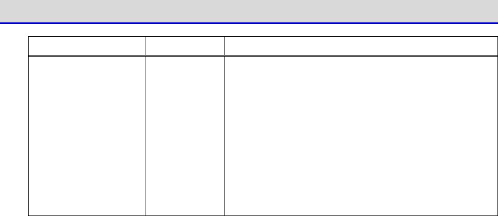
1-1-3 Name and Function of Each Unit
⑱Hand Strap
①LED Ind icato r
②LCD W ind o w
⑧Barcode
W ind o w
⑩Lo ck Lever
⑫Charg ing Term inal
⑪Battery Cover
⑨Trig g er Key
③SCAN Key
⑦Hand Strap Attaching Ho le
⑬Pro d uct N am ep late
⑤IrDA Co m m unication Port
④Op eratio n
Keyp ad
⑯Battery Pack
⑮Electro d es
⑭m icro SD Card Slo t
⑥Sp ea ker
⑰Serial N um b er
Seal
ワイ ヤレス二次元
ハンディターミ ナル
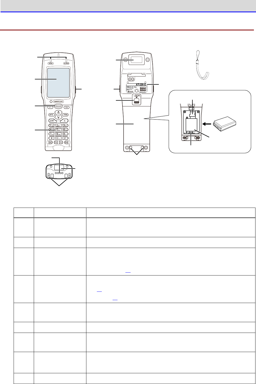
No. Name Description
① LED Indicator Two different LED displays (SCAN and ALARM) display the in
formation
(see next section, "■LED indicator").
② LCD Window Displays characters and images.
③ SCAN Key Pressed when reading barcodes.It is also used when forcibly
launching the system menu (see "1-3-3 Useful Features during
Operation" (P.55).
④ Operation Keypad For names of the respective keys, see "■Names of Operation Keys"
(P.32).For operations of the respective keys, see "4-1-1
Operation
Keys" (P.92).
⑤ IrDA Port The infra-
red (IrDA) system enables you to communicate with other
handy terminals or USB communication units.
⑥ Speaker Makes the sound of a buzzer or other devices.
⑦ Hand Strap At-
taching Hole
Used for attaching the hand strap.
⑧ Barcode Window A window for reading barcodes.
*Do not look into the window as it is irradiated with laser light.
⑨ Trigger Key Pressed when reading barcodes.

Chapter 1 Hardware 1-1 About the Handy Terminal
GTX-221-G User’s Manual
30
No. Name Description
⑩ Lock Lever Locks/releases the battery cover.Moving the lever in the
direction
of the arrow locks the cover.
⑪ Battery Cover This is the cover of the battery pack compartment.
A function has
been included for detecting whether the battery cover has been
closed properly. The Handy Terminal
cannot be started if the cover
is not closed properly.
⑫ Charging Terminal Charging terminals for both single chargers and multi chargers.
⑬ Product Name Plate
Provides product name, manufacturer
’
s name, laser warning, etc.
⑭ microSD Card
Slot
Used for inserting a microSD card.Lift th
e cover and insert the
card.
⑮ Electrodes Electrodes to draw power from the battery pack.
⑯ Battery Pack The supplied lithium ion secondary battery.
⑰ Serial Number Seal
Displays the serial number.
Please provide this serial number in case of any product-
related
inquiry.
⑱ Hand Strap Used after being attached to
Hand Strap Attaching Hole.
Chapter 1 Hardware 1-1 About the Handy Terminal
GTX-221-G User’s Manual
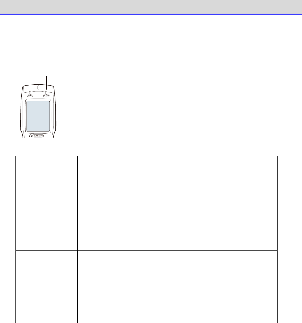
31
■LED indicator
The respective LED indicators indicate the following operation statuses.
SCAN
LED
ALARM
LED
SCAN LED Can control LED ON / Blink / LED OFF at any timing from an ap-
plication software.
Indicates charging in progress and charging completed while placed
in a charger slot.
【While Charging】
Green: Charging completed
Red: Charging in progress
LED OFF: Charging error
ALARM LED Indicates the communication status while WLAN is being used.
Orange LED ON: Out of range while WLAN is enabled
Orange Blinking: Authentication in progress while WLAN is enabled
LED OFF: Within range while WLAN is enabled
Can control LED ON / Blink / LED OFF at any timing from an ap-
plication software while WLAN is disabled
Chapter 1 Hardware 1-1 About the Handy Terminal
GTX-221-G User’s Manual
32
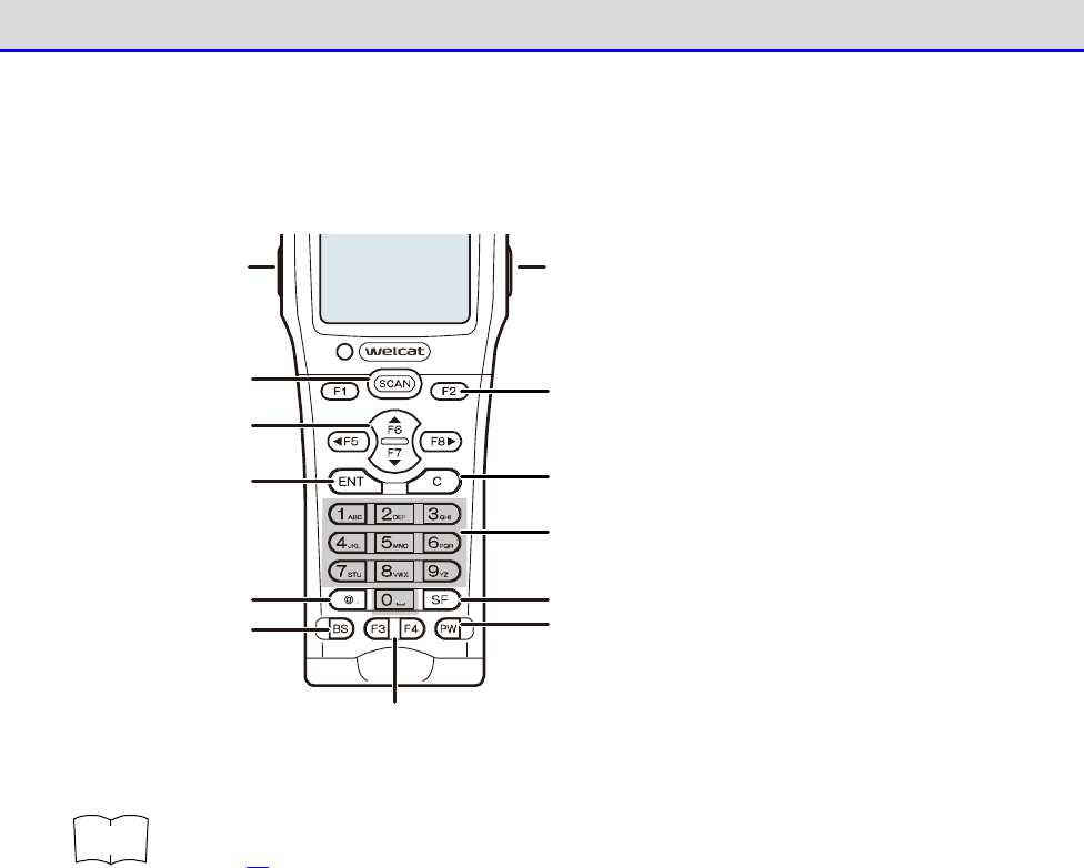
■Names of Operation Keys
The names of the operation keys are as follows:
Function key
Function key
A
rrow k ey (F5 ~F8 )
ENT key C key
BS key
Ten key
Dot ( .) key
PW key
SCAN key
SF key
Trig g er key Trig g er key
r
rr
re
ee
ef
ff
f
For operations of the keys during system menu operation, see "4-1-1 Operation Keys"
(P.92).
Chapter 1 Hardware 1-1 About the Handy Terminal
GTX-221-G User’s Manual
33
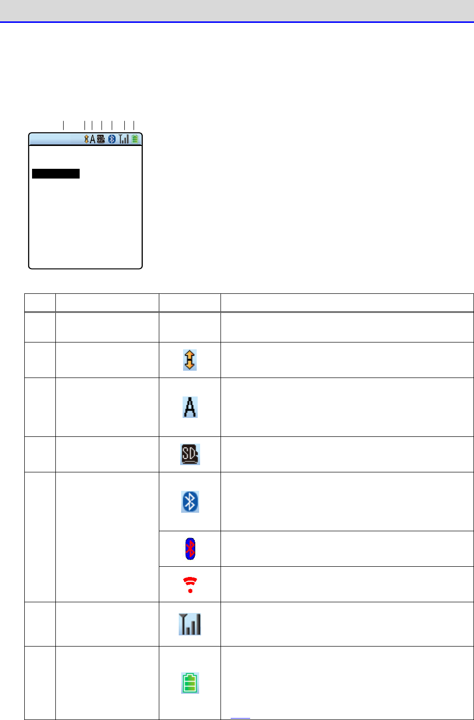
■LCD Screen Status Bar
The status bar indicating the status of the Handy Terminal is located at the top of the LCD
screen.
← S ta tu s b a r
① ② ③ ④ ⑤ ⑥ ⑦
< System menu >
1:System 6:ID
2:WLAN 7:D evice
3:Network 8:Manage
4:Receive 9:Test
5:File
The status bar displays the following information:
No.
Name Icon Description
① Text Display Area
–
Used to display text, depending on the application
software.
② Scroll
Displayed when vertically scrollable depending on the
application software.
③
Type of the Entered
Text
Indicates the type of text entered from the numeric
keypad.
"A" is displayed when an alphabetic character
is entered, and "1" is displayed when a numeric
character is entered.
④ SD Card
Displayed when a microSD card is inserted.
Displayed while Bluetooth connection exists with
another device and transmission/reception is pos-
sible.
Displayed in red while there is no Bluetooth
connection with another device.
Displayed while Bluetooth is enabled, but no con-
nection exists with another device.
⑤ Communication
Status
Displayed while transmission/reception using in-
frared communication (IrDA) is possible.
⑥ WLAN Status
Indicates the radio field intensity during WLAN
communication. The number of bars decreases as
the
radio field intensity becomes weaker.
⑦ Battery Pack
Indicates the current charge level in the battery
pack.
The number of bars decreases as the charge level
in the battery pack decreases (see "1-2-5
Remaining
Charge Level Display and Alarm for the Battery Pack"
(P.48)).
Chapter 1 Hardware 1-2 How to Use the Handy Terminal
GTX-221-G User’s Manual
34
1-2 How to Use the Handy Terminal
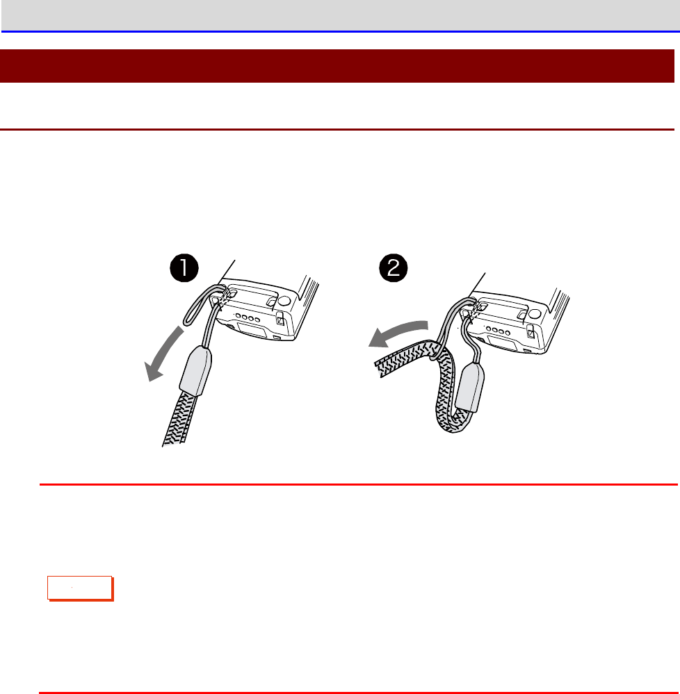
1-2-1 Attaching the Hand Strap
The hand strap attaching hole is located at the bottom of the back side.
①Push the thin loop at the top of the hand strap through the attaching hole.
②Pass the hand strap through the loop that has been inserted through the attaching hole.
C
a
u
t
i
o
n
・Please do not swing the Handy Terminal while holding the hand strap. The thin
loop may wear down and break.
・Be fully aware that in cases such as the Handy Terminal is caught by a movable
device while the hand strap is around your wrist, your hand may be yanked, leading
to injury.
・When charging the Handy Terminal using the multi charger (QC-007), bring the
hand strap to the front right of the Handy Terminal so that it will not get caught
in the charging terminals.
Chapter 1 Hardware 1-2 How to Use the Handy Terminal
GTX-221-G User’s Manual
35
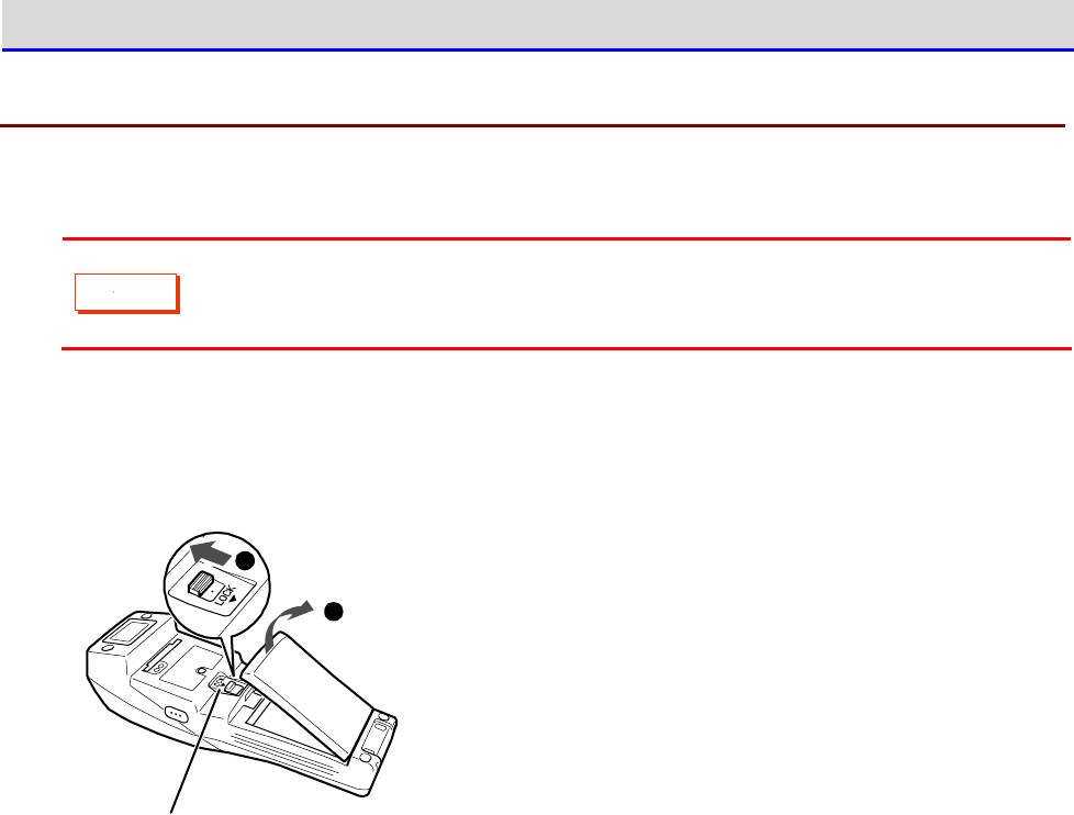
1-2-2 Handling the Battery Pack
■Attaching the Battery Pack
C
a
u
t
i
o
n
・Do not use any battery pack other than that specified.
・Be sure to charge the battery pack before using it for the first time.
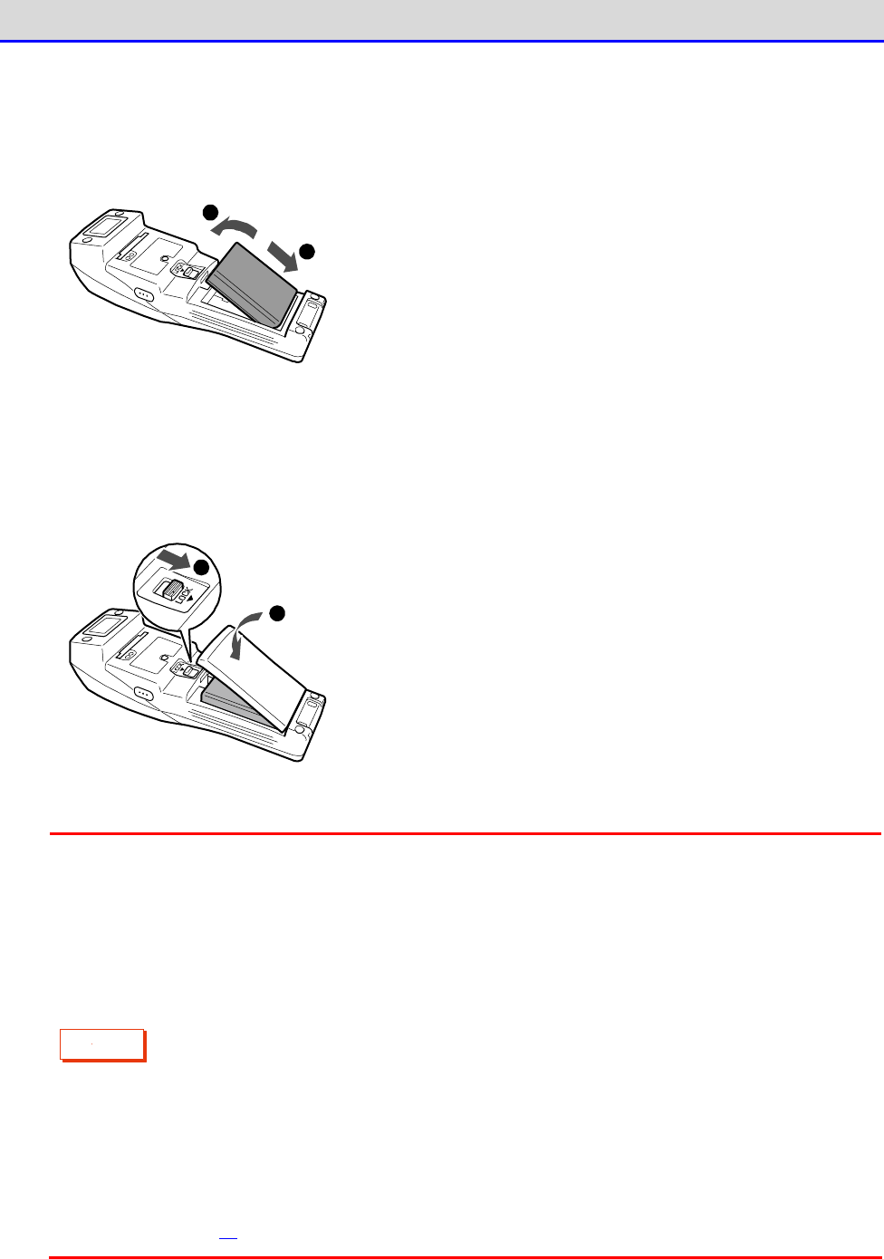
①To release the lock, move the lock lever in the arrow direction (towards the Barcode window).
②Pull the battery cover toward you from the lock lever side.
2
1
Lo ck le ver
③Holding the battery pack with the label side facing upward, move it forwards so that its
terminals make contact with the electrodes of the Handy Terminal.
Chapter 1 Hardware 1-2 How to Use the Handy Terminal
GTX-221-G User’s Manual
36
④After verifying that the battery pack terminals and the Handy Terminal electrodes have made
proper contact, press down the opposite side of the battery pack.
1
2
⑤Insert the claws of the battery cover into the Handy Terminal till the lock lever clicks,
with its other side closely in contact with the Handy Terminal. Press till the lock lever
is properly located at its lower extreme position.
1
2
C
a
u
t
i
o
n
・Verify that the lock lever has completely moved down in the arrow direction
(towards the battery pack), leaving no gap.If this locking is not done properly,
the battery pack may detach or fall off and get damaged.
・If the battery cover has not been closed correctly, the Handy Terminal cannot
be started.
・A gasket has been fitted into the battery cover in order to prevent water
ingress.When attaching the cover, verify that the gasket has not become detached
and that there is no adhering waste material.In case any adhering waste material
is found, wipe it off with a dry and clean cloth.
・Do not touch or pull the electrodes.This may cause contamination and/or
deformation of the electrodes, leading to poor contact. If the electrodes are
dirty, wipe them using a clean and dry cloth (see "1-4 Maintenance Method"
(P.57)).
Chapter 1 Hardware 1-2 How to Use the Handy Terminal
GTX-221-G User’s Manual
37
■Detaching the Battery Pack
You can detach the battery pack from the Handy Terminal.
C
a
u
t
i
o
n
・Before detaching it, verify that the power has been completely turned off.
・If you open the battery cover during operation, a warning message will be
displayed. Before replacing the battery pack, save the data, terminate the
application software, and then turn off the power.
・If you detach the battery pack while file write (data communication, file
reception, backup) is in progress, the file may get corrupted.
Take measures such as deleting the file or recovering the data after transferring
the data to a PC or other locations.
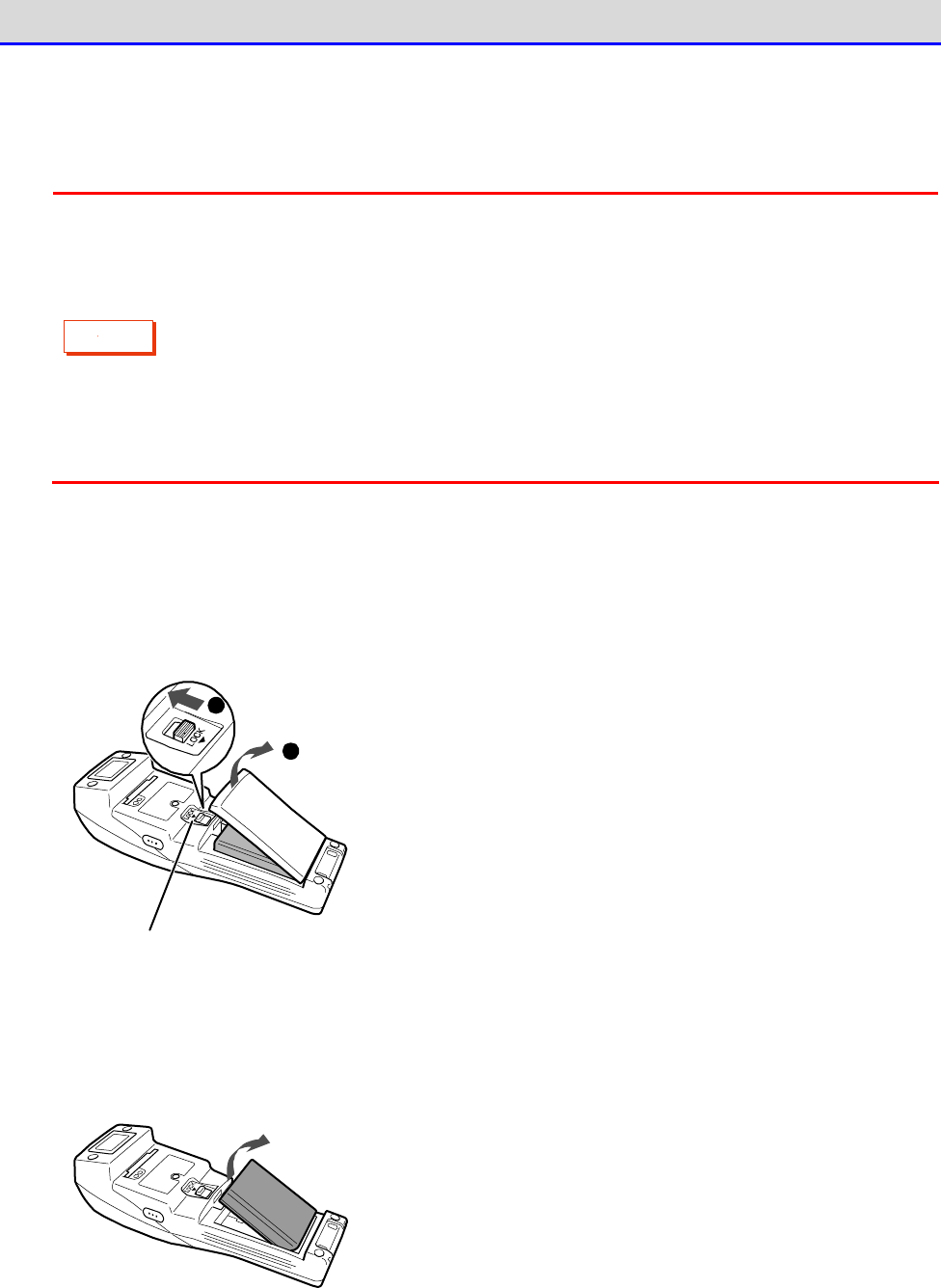
①To release the lock, move the lock lever in the arrow direction (towards the Barcode window).
②Pull the battery cover toward you from the lock lever side.
Lock lever
2
1
③Lift the back end of the battery pack (Barcode window side) and take it out.
Chapter 1 Hardware 1-2 How to Use the Handy Terminal
GTX-221-G User’s Manual
38
1-2-3 Handling the microSD Card
You can attach a microSD card to the Handy Terminal and save the data using it as the R drive.
C
a
u
t
i
o
n
・Use a tested microSD card.
・Before attaching or detaching the card, verify that the power has been completely
turned off.
・If you open the battery cover, a warning message will be displayed. Before opening
the battery cover, save the data, terminate the application software, and then
turn off the power.
■Tested microSD Card
For tested microSD cards, contact your dealer.
Chapter 1 Hardware 1-2 How to Use the Handy Terminal
GTX-221-G User’s Manual
39
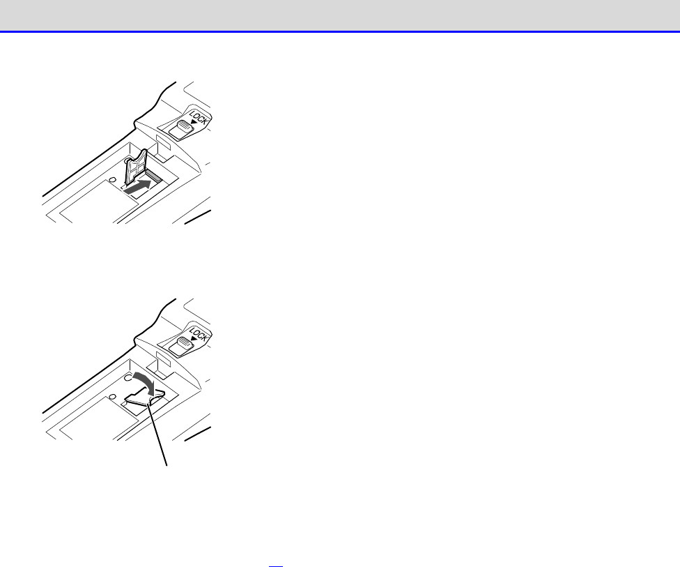
■Installing the microSD Card
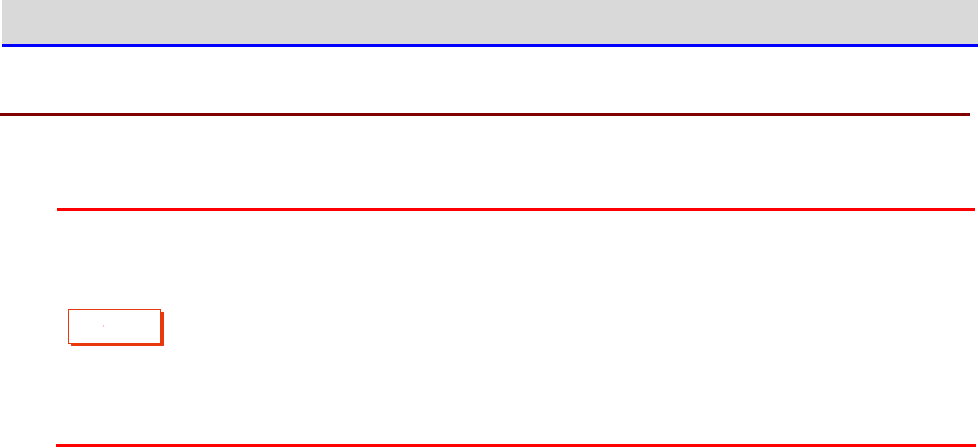
①Detach the battery pack (see "■Detaching the Battery Pack" (P.37)).
②Lift the microSD card cover.
m ic ro SD car d co ver
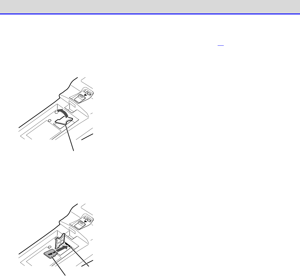
③Insert the microSD card into the slot. At this time, hold the card with its electrode side
facing downward and its arrow mark (
▲
) pointing toward the slot.
m icro SD ca rd
Slot
Chapter 1 Hardware 1-2 How to Use the Handy Terminal
GTX-221-G User’s Manual
40
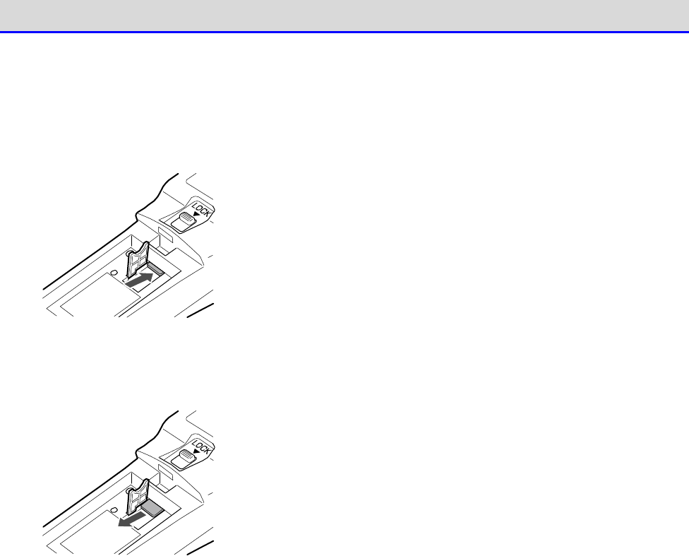
④Push the microSD card into the slot till it "clicks".
⑤Return the cover of the microSD card to its original position.
m ic ro SD car d co ver
⑥Attach the battery pack, and return the battery cover to its original position (see "■
Attaching the Battery Pack
“
(P.35)).
Chapter 1 Hardware 1-2 How to Use the Handy Terminal
GTX-221-G User’s Manual
41
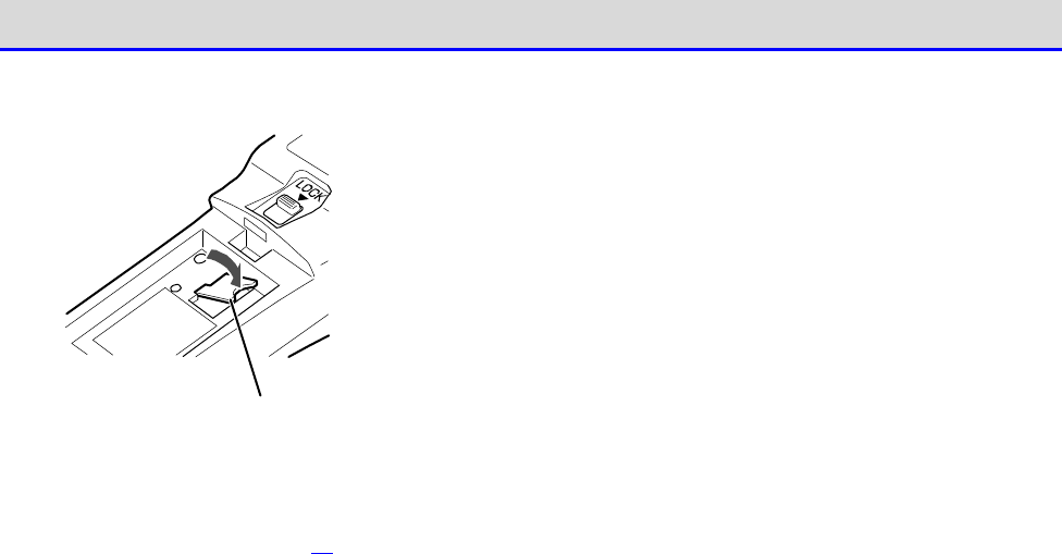
■Detaching the microSD Card
①Detach the battery pack (see
“
■Detaching the Battery Pack
”
(the previous page)).
②Lift the microSD card cover, and push the microSD card into its slot till it "clicks".
③The lock is released, and the microSD card comes out partly. Then, pull out the card using
your fingers.
Chapter 1 Hardware 1-2 How to Use the Handy Terminal
GTX-221-G User’s Manual
42
④Return the cover of the microSD card to its original position.
m ic ro SD car d co ver
⑤Attach the battery pack and return the battery cover to its original position (see
“
■Attaching
the Battery Pack
”
(P.35)).

Chapter 1 Hardware 1-2 How to Use the Handy Terminal
GTX-221-G User’s Manual
43
1-2-4 Charging the Battery Pack
The Handy Terminal is charged using a dedicated charger (available separately). There are two
charging methods: Handy Terminal charging and battery pack charging.
・Handy Terminal charging: Charging the Handy Terminal with the battery pack attached.
・Battery pack charging: Charging the battery pack separately.
The charger has the following types:
・Charging one unit: Single charger (QC-006) or USB communication/charging unit (IU-004C)
・Charging multiple units (up to four units): Multi charger (QC-007)
C
a
u
t
i
o
n
・Operating the Handy Terminal keys during charging may lead to poor contact with
charging terminals. Do not perform key operations during charging. Otherwise,
charging or file transfer may be interrupted.
・Perform charging in an environment of 0
°
C - 40
°
C. Charging error will occur and
charging will be terminated if the temperature is outside this range.
Even after a charging error appears, charging will resume if the temperature
enters the acceptable range. However, as this may lead to trouble, be sure not
to use it outside 0
°
C - 40
°
C.
・Charging error may occur if the terminals of the Handy Terminal or the battery
pack do not make proper contact, If charging is not completed within the
specified time or if the voltage of the battery pack becomes abnormal.
In such cases, stop charging immediately.If charging error persists even after
you have cleaned the charging electrodes of the Handy Terminal and the terminals
of the battery pack, please contact your dealer,
・If the Handy Terminal does not start even after being charged, or if low battery
occurs within an extremely short time, the following reasons are considered:
□Deterioration of the Battery Pack
The battery pack deteriorates with repeated charging, and the chargeable
capacity becomes low. Replace it with a new battery pack if its operating
time becomes short and is not suitable for operation.
□Poor Contact of the Charging Terminal Electrodes
If the electrodes of the charging terminals of the battery pack or the Handy
Terminal have become dirty, charging may not be performed normally due to
poor contact.In such a case wipe the electrodes using a clean cloth.
Chapter 1 Hardware 1-2 How to Use the Handy Terminal
GTX-221-G User’s Manual
44
●Charging Status
The charging status of the Handy Terminal is displayed by the SCAN LED on the Handy Terminal.
The battery pack charging status is displayed by the CHG LED on the charger.
Charging Status SCAN LED
CHG LED
Charging
Red LED ON
Red LED ON
Charging Completed
Green LED ON
Green LED ON
Charging Error
LED OFF
LED OFF
●Handy Terminal Charging Time
Approximately 2.5 hours
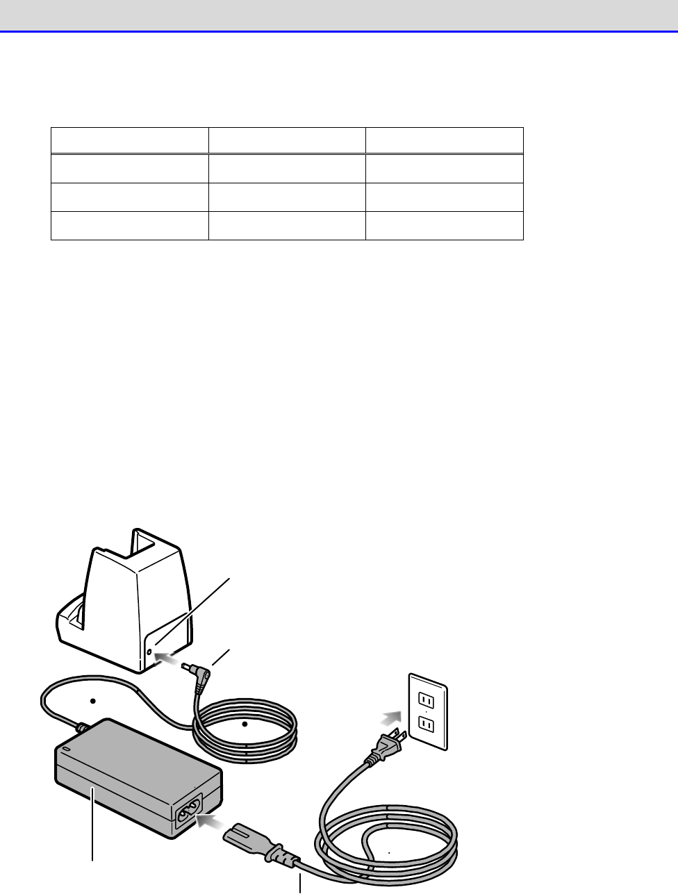
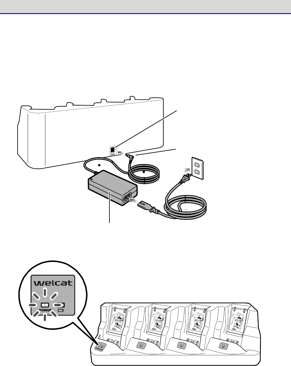
■Charging One Unit
Perform charging by the following procedure:
①Insert the DC plug of the AC adapter into the DC jack located on the back of the charger.
Connect the AC cord to the AC adapter, and then connect the plug of the AC cord to the mains
outlet.
DC jack
AC adap ter
DC p lug
AC cord
Chapter 1 Hardware 1-2 How to Use the Handy Terminal
GTX-221-G User’s Manual
45
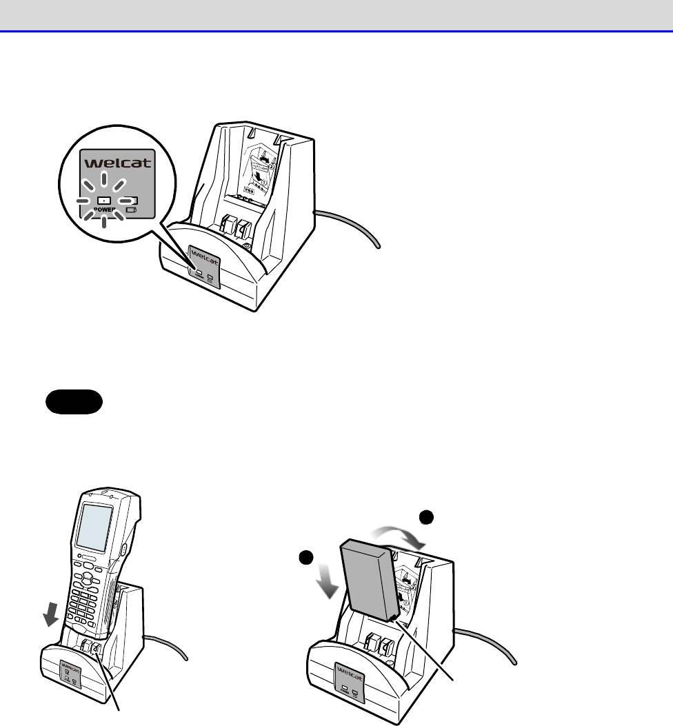
Verify that the POWER LED on the front of the charger is turned on in red.
②Mount the Handy Terminal or the battery pack on the charger.
Hint
When the Handy Terminal and the battery pack are both mounted at the same time,
charging the Handy Terminal takes precedence. Once charging of the Handy Terminal
is completed, charging of the battery pack is started.
Ch ar g in g te rm in al
1
2
Charg ing term inal
P
lace the battery
p
ack charg ing
t
erm inal o n the
c
harg er charg ing
t
erm inal.
Pu sh th e b atte ry
pack ag ainst the
charg er u ntil it is
click-latched on
the charg er.
The above figures show examples for the single charger (QC-006).
Insert the battery pack with its terminal side downward and with the side displaying the product
model No. (BP-004) and other information facing you. Bring the terminals of the battery pack
in contact with the charging terminals of the charger, and press till they click so that the
claws are hooked.
To charge the Handy Terminal and the battery pack at the same time, attach the battery pack
first.
Chapter 1 Hardware 1-2 How to Use the Handy Terminal
GTX-221-G User’s Manual
46
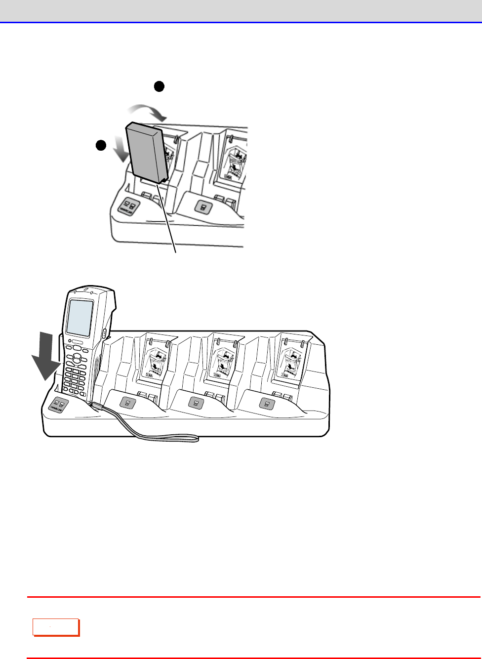
■Charging Multiple Units
You can charge multiple units using the multi charger (QC-007).
①Insert the DC plug of the AC adapter into the DC jack that located on the back of the charger.
Connect the AC cord to the AC adapter, and then connect the plug of the AC cord to the mains
outlet.
DC j ack
AC adap ter AC co rd
DC plug
Verify that the POWER LED on the front of the charger is turned on in red.
Chapter 1 Hardware 1-2 How to Use the Handy Terminal
GTX-221-G User’s Manual
47
②Mount the Handy Terminal or the battery pack on the charger.
1
2
Charg ing terminal
P
lace the battery
p
ack charg ing
t
erm inal on the
c
harg er charg ing
t
erm inal.
Push the battery
pack ag ainst the
charg er until it is
click-latched on
the charg er.
Insert the battery pack with its terminal side downward and with the side displaying the product
model No. (BP-004) and other information facing you. Bring the terminals of the battery pack
in contact with the charging terminals of the charger, and press till they click so that the
claws are hooked.
To charge the Handy Terminal and the battery pack at the same time, attach the battery pack
first.
C
a
u
t
i
o
n
When charging the Handy Terminal using the multi charger (QC-007), bring the hand
strap to the front right of the Handy Terminal so that it will not get caught
in the charging terminal unit.
Chapter 1 Hardware 1-2 How to Use the Handy Terminal
GTX-221-G User’s Manual
48
1-2-5 Remaining Charge Level Display and Alarm for the Battery
Pack
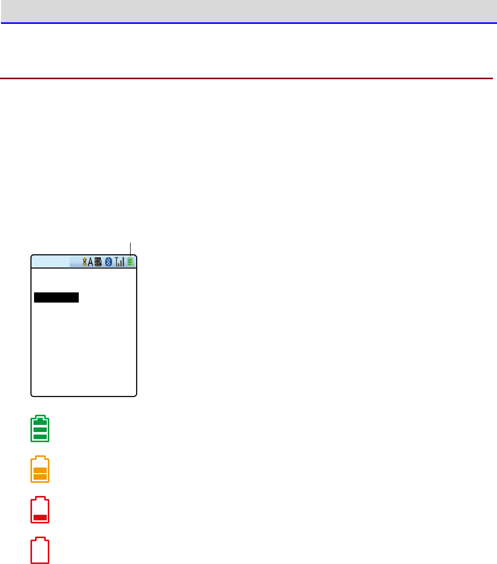
■Remaining Charge Level Display for the Battery Pack
If the battery pack
’
s remaining charge level becomes low, the operations are disabled. And then,
the power is turned off.
The battery pack
’
s remaining charge level is displayed in the status bar at the top of the LCD
screen.
R em ain in g b attery p a ck p o w er ico n
< System menu >
1:System 6:ID
2:WLAN 7:Device
3:Network 8:Manage
4:Receive 9:Test
5:File
The battery
’
s remaining charge level is sufficient.
The battery
’
s remaining charge level is getting low.
The battery
’
s remaining charge level is insufficient. Please charge it.
The battery has no charge left.Charge your battery pack immediately or replace it with
a charged battery pack.
Chapter 1 Hardware 1-2 How to Use the Handy Terminal
GTX-221-G User’s Manual
49
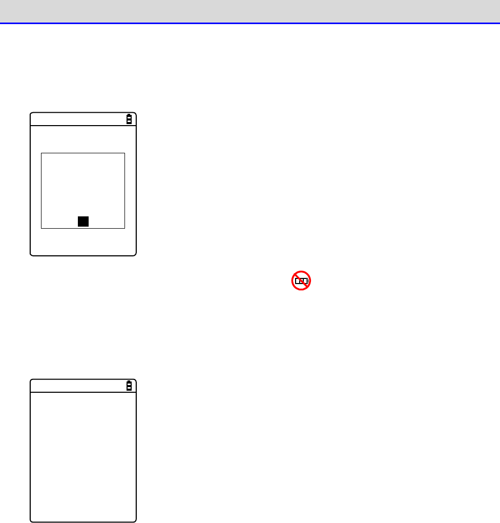
●Limitations when the remaining battery pack power becomes insufficient
Some operations of the system menu are disabled and the following screen is displayed, when
the remaining battery pack power icon shows one bar or no bars (varies depending on the
operations).
< File list >
< Low-battery >
Battery voltage
is low.
Therefore the
operation cannot
be executed.
OK
This manual displays the disabled operations using .
●Low Battery Display
After the remaining battery pack power icon displays empty (no bars), if the voltage falls even
lower, the following screen is displayed, and the power is forcibly turned off after ap-
proximately five seconds.
[ Battery Alert ]
Voltage is low.
Please charge it.
■Charging the Backup Battery
The Handy Terminal has a built-in backup battery for backing up the system information. Charge
the backup battery using the following procedure:
①Prepare a fully charged battery pack.
②As soon as the battery pack is attached to the Handy Terminal, the backup battery starts to
be charged.
If the backup battery has been completely depleted, charging requires at least 24 hours.During
this time, do not detach the battery pack.
Chapter 1 Hardware 1-2 How to Use the Handy Terminal
GTX-221-G User’s Manual
50
1-2-6 Memory Backup
The Handy Terminal has two drives as file save areas: the F drive (non-volatile) and the S drive
(volatile).As the application data downloaded from the PC is saved in the F drive, the data
will not disappear even if the battery pack has been depleted (see "2-1-1 About Data"-"■
Drive Configuration" (P.59)).
Backup is performed using the battery pack and the backup battery.
■Memory Backup
●Memory Backup by Battery Pack
Backup Period
The data storage period while the fully
charged battery pack is attached
is as follows:
・The data and the resume information in the S drive: Approximately 10 days
Usage Notes
If the battery pack has been detached during operation, or the memory backup
function on the system menu has been disabled, the data and resume in-
formation in the S drive will disappear.To save the information tempo-
rarily, be sure to enable the memory backup function, press the【PW】
key,
turn off the power, and then detach the battery pack. For the resume
function , see "■Resume Function: Retaining the State during Power OFF
"
(P.107).
The backup period will become extremely short after about six months if
you repeat operations such as detaching the battery pack when you d
o not
use the Handy Terminal (making full use of memory backup by the backup
battery) on a daily basis.
In such a case, you will need to replace the
backup battery by purchasing a new battery. Therefore, it is recommended
to always keep the battery pack attached except when replacing it.
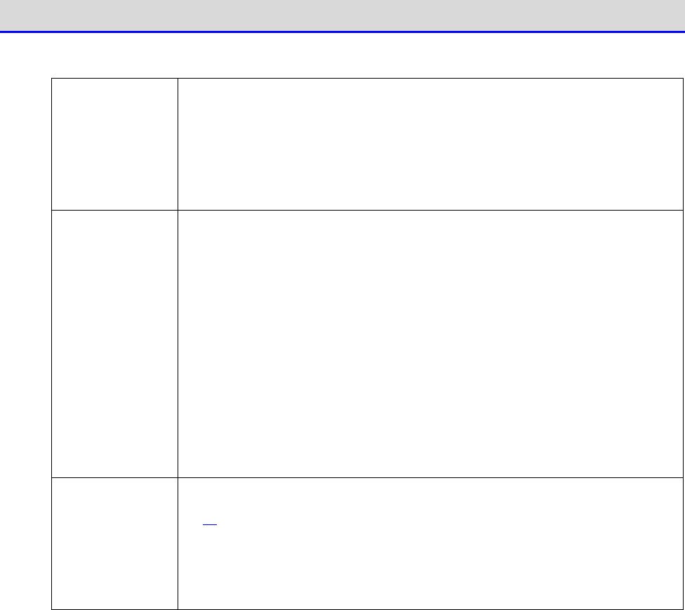
Chapter 1 Hardware 1-2 How to Use the Handy Terminal
GTX-221-G User’s Manual
51
●Memory Backup by Backup Battery
Purpose
To retain the built-in clock data in the Handy Terminal.
Or to save the
S drive data only for a certain period, such as in case of battery pack
replacement.
If the resume function has been enabled, the resume inform
ation will be
saved.
Backup Period
The data storage period while the battery pack is detached after normal
end
*1
is as follows:
・
The resume information and data in the S drive (if the resume function
is enabled): Approximately 10 days
・Built-in clock data: Approximately 6 months
The data storage period when end occurs due to mothball setting
*2
is as
follows:
・Built-in Clock Data: Approximately 1 year (regardless of whether the
battery pack is attached or not)
The above mentioned are actual values but are not guaranteed.
Usage Notes
For long-term storage of the Handy Terminal, see "1-2-7 Long-term Storage"
(P.52).
Data that has been lost due to depletion of the backup battery cannot be
recovered. Save any data other than temporarily required data in the F
drive.
*1 Normal End: End method by which the battery pack is detached after the【PW】Key is pressed
*2 End by Mothball Setting: End method by which mothball is selected from the system menu
■Charging the Backup Battery
The Handy Terminal has a built-in backup battery for backing up the memory and the built-in
clock.Charge the backup battery using the following procedure:
①Prepare a fully charged battery.
②As soon as the battery pack is attached to the Handy Terminal, the backup battery starts to
be charged.
If the backup battery has been completely depleted, charging requires at least 24 hours.During
this time, do not detach the battery pack.
Chapter 1 Hardware 1-2 How to Use the Handy Terminal
GTX-221-G User’s Manual
52
1-2-7 Long-term Storage
■Long-term Storage of the Handy Terminal
It is recommended that you enable the mothball setting if the Handy Terminal is not going to
be used for a long term (six months or longer).
Enabling the mothball setting shuts down the power immediately.
The data and the resume information in the S drive will disappear after the mothball setting
is enabled, but the built-in clock data continues to be retained. This, therefore, can reduce
the consumption of the backup battery.
For how to enable the mothball setting, see "4-10-5 Mothball: Settings When Not Using the Product
For Long" (P.196).
■Long-term Storage of the Battery Pack
If the battery pack is not to be used for a long term, it is recommended that you enable the
above-mentioned mothball setting for the Handy Terminal, detach the battery pack, and store
it in a cool place with it approximately 50% charged. Storage with full charge or in a
high-temperature environment shortens the service life of the battery pack.
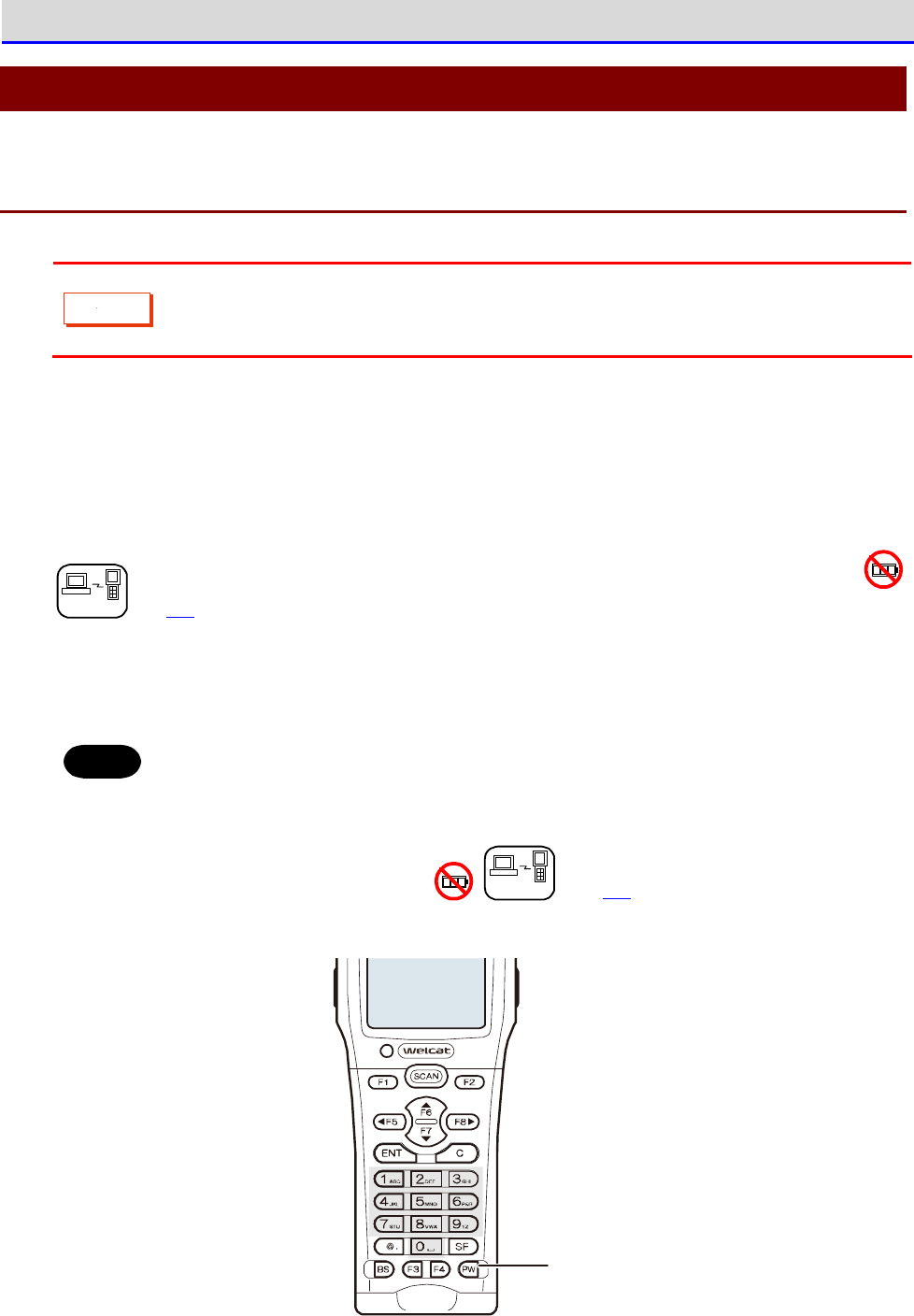
Chapter 1 Hardware 1-3 Basic Usage Method
GTX-221-G User’s Manual
53
1-3 Basic Usage Method
1-3-1 Power ON/OFF
C
a
u
t
i
o
n
Power ON is not available unless the battery cover is completely closed.
If you open the battery cover during operation, a warning message is displayed.
To turn on the power, press the【PW】key for at least 1 second.
*When you first turn on the power after attaching the battery pack, you need to press the
【PW】key for at least two seconds.
When auto execution of application software has been set, the selected application software
is started (see "4-3-1 Auto Execute: Automatic Execution of the Application Software
DHCP
"(P.103).
To turn off the power, press the【PW】key.
Hint
・To launch the system menu, press the【PW】Key for at least one second while holding
down the【SCAN】Key.
・When auto execution of application software has been set, the selected ap-
plication software is started (see "4-3-1 Auto Execute: Automatic Execution of
the Application Software
DHCP
" (P.103).
PW key
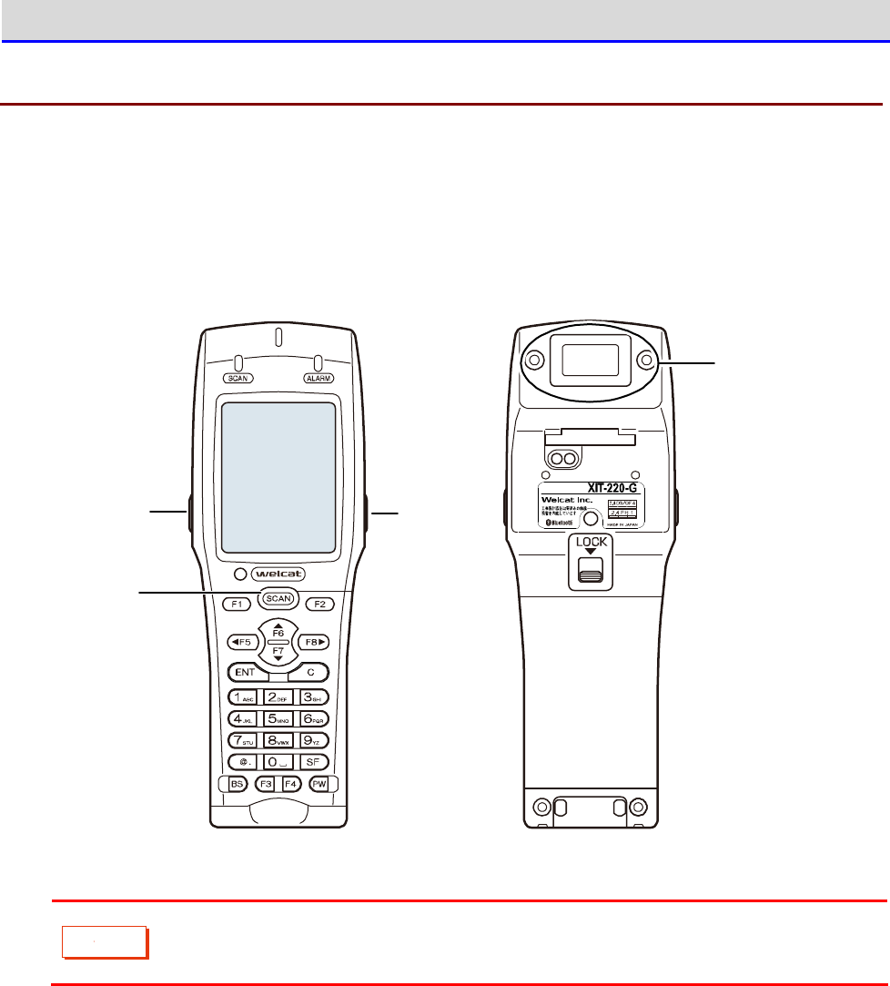
Chapter 1 Hardware 1-3 Basic Usage Method
GTX-221-G User’s Manual
54
1-3-2 How to Read a Barcode
■Read Method
When reading a barcode, make the Barcode window on the back side to face the barcode, and then
press the【SCAN】Key or the trigger keys located on the left and right.
Trig g er key
Trig g er key
SCAN key
Barcode
wind o w
ワイヤレス二次元
ハンディターミナ ル
C
a
u
t
i
o
n
Laser light is irradiated from the Barcode window. Do not look into the Barcode
window or look at the laser light.
Chapter 1 Hardware 1-3 Basic Usage Method
GTX-221-G User’s Manual
55
1-3-3 Useful Features during Operation
■Forcible Startup on the System Menu
In the power OFF state, when the Handy Terminal is started by pressing the【PW】Key while holding
down the【SCAN】key, the system menu is forcibly launched even when "Auto execute" is set on
the application software.
■Auto-dimming Setting
The Handy Terminal has a built-in ambient light sensor which senses the surroundings and
automatically controls the dimming of the LCD backlight and the lighting of the key backlights.
On the system menu, select [7:Device]-[4:Display]-[2:SetAlsSensor] and make the setting.
However, when the backlight is set to remain bright for a certain time after key entry, it will
go dim after being lighted up for the set time.
■Buzzer Volume Adjustment
You can adjust the buzzer volume, the key click sound, etc.
On the system menu, select [7:Device]-[5:Tone/Vibrator] and make the setting.
r
rr
re
ee
ef
ff
f
For its detailed setting method, see "4-9-5 Tone/Vibrator: Setting the Volume,
LED, and the Vibrator" (P.178).
Chapter 1 Hardware 1-3 Basic Usage Method
GTX-221-G User’s Manual
56
■Resume Function (Retention of the State during Power OFF)
If the resume function is enabled, the state when the power was turned OFF is saved, allowing
you to resume your work thereafter upon the next startup.
You can select the operations on power resumption when selecting [1:System]-[3:Power
Management]-[2:Resume].
r
rr
re
ee
ef
ff
f
For its detailed setting method, see "4-3-3 Power Management: Various Settings
Related to Power" (P.107).
C
a
u
t
i
o
n
・If the battery pack is removed during operation, upon the next startup the initial
screen will be launched regardless of whether the resume function is enabled
or disabled.
・If the backup battery is depleted, the initial screen will be started from the
start regardless of the enable/disable state of the resume function. For
charging the backup battery, see "1-2-6 Memory Backup" (P.51)
■Auto Wakeup (Power ON after Preset Time)
If the auto wakeup function is enabled, the Handy Terminal can be started automatically according
to a preset schedule.
In the settings of the auto wakeup function, select [1:System]-[3:Power Management]
―
[2:Auto wake up].
r
rr
re
ee
ef
ff
f
For its detailed setting method, see "4-3-3 Power Management: Various Settings
Related to Power"-"Auto Wakeup: Startup at a Predetermined Time" (P.109)
■Auto Power OFF (Automatic Power OFF)
If no operation is performed for a certain time, the power will automatically be turned OFF.
You can set the time after which the power is turned OFF when selecting <1:System> > <3:Power
Management> > <3:Auto power off> on the system menu.
r
rr
re
ee
ef
ff
f
For its detailed setting method, see "■Auto Power OFF: Automatic Power OFF"
(P.111).
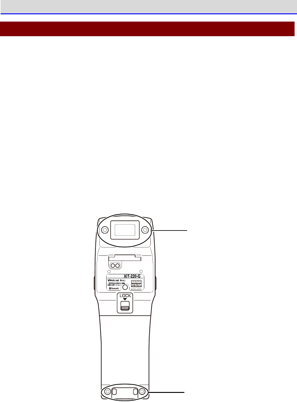
Chapter 1 Hardware 1-4 Maintenance Method
GTX-221-G User’s Manual
57
1-4 Maintenance Method
・Barcode Window
If the filter of the Barcode window becomes dirty, the barcode may not be read correctly.
・Electrodes
If certain symptoms start to appear, such as the operating time of the battery pack becoming
short, startup becoming difficult, or the power turning off suddenly, the reasons may include
deterioration of the battery pack and poor contact due to dirty electrodes. If dirty electrodes
are the reason, you can improve the performance by cleaning the electrodes of the battery
pack and the Handy Terminal.
●Cleaning Method
Wipe the dirt off the Barcode window's filter and/or electrodes using a clean, dry, and soft
cloth, swab, etc.Be sure not to rub with dirty cloth, fingers, or hard objects.Be aware that
wiping strongly may cause damage. Particularly, because the electrodes on the Handy Terminal
side may get deformed, please wipe them gently.
Barco d e
wind ow
Electrod es
ワイヤレス二次元
ハンディターミナル

Chapter
2
Software
Chapter 2 Software 2-1 About Software
GTX-221-G User’s Manual
59
2-1 About Software
The software of the Handy Terminal is of the following two types:
System Programs
The programs that control the basic operations of the Handy Terminal.
They are equivalent to the PC OS (basic software) a
nd are preinstalled
on the Handy Terminal.
"System Menu", which is used for performing basic
settings for basic operation parameters and for various verifications,
is part of the system programs.
Application
Software
The programs used for business processes.
These programs are mainly used for reading barcodes, transferring data
to a PC, etc.
You need to create them using the development environment
of "2-3 Create an Application Software" (P63).
2-1-1 About Data
■Drive Configuration
As areas for storing data, the Handy Terminal has the F drive / the C drive inside itself, and
the R drive in the microSD card.
Drive
Data Retention
Purpose
Maximum Number of Files
Saved
F Drive
Non-volatile memory
Even after the backup
battery is used up, the
drive data is still re-
tained.
This drive is used as an area
to store all the files in-
cluding ap
plication software,
database master files, and
data files.
128 files
S Drive
Volatile memory
During operation, if the
battery or the battery
pack is suddenly de
tached
or if the backup battery
is depleted, the drive
data will disappear.
This drive is used as an area
to store temporary files
while the application
software is running.
128 files
R Drive microSD Card
Even after the backup
battery is depleted, the
drive data is still re-
This drive is used as an
ex
ternal extension area for
storing files in the microSD
card.
V
aries depending on the
card.
Chapter 2 Software 2-1 About Software
GTX-221-G User’s Manual
60
tained.
C
a
u
t
i
o
n
・To receive files, the files first are received using the S drive and then moved
to the F drive and stored therein. Verify that both the S drive and the F drive
have adequate areas for receiving and storing the files.
・When receiving files, if some files in the S drive have the same names as the
files being received, they will be erased.
■About File Name
File names that can be used in the Handy Terminal have the following limitations:
Limitation Details
File Name Length
Within 31 bytes including the file extension
Characters that
can be used
Any combinations of the following characters can be used:
・Alphabets (A
–
Z)
・Numerals (0
–
9)
・Some symbols (!#%&'()@^_{}
~
.)
・Half-width space
・SHIFT JIS full-width characters
Other limitations
Space and "." (period) cannot be used at the beginning
of a file name.
■About File Extension
The Handy Terminal identifies the file types using the following file extensions:
File Extension
Purpose
OUT Application Software
JPG
PNG
BMP
JPEG
Image files that can be displayed on the Handy Terminal.
WAV
SFL
Audio files that can be played on the Handy Terminal.
Chapter 2 Software 2-1 About Software
GTX-221-G User’s Manual
61
■Files Created by the System or the Application Software
The system programs and some application softwares create temporary files and files for saving
settings. If these files cannot be created, due to reasons such as there are too many files
or there is no free space in the drive, the programs may not run properly.
The system program creates a registry file in the F drive in order to save the setting values
of the system menu. Four files are created, but they are not displayed on the system menu as
they are hidden files.
r
rr
re
ee
ef
ff
f
For registries, see "2-2 Registry" (P.62).

Chapter 2 Software 2-2 Registry
GTX-221-G User’s Manual
62
2-2 Registry
The various parameters set on the system menu are called "Registry".
As the register file is a hidden file, it cannot be displayed on the system menu. In addition,
as it is saved in the F drive, it will not disappear even when the battery is depleted.
The registry is divided into the following five categories.
Registry
General setting values.Most items set on the system menu belong to
the user registry.
Security Registry
Setting values related to security, such as WEP key and SSID.
Unique Registry
Setting values specific to the terminal, such as IP address and
terminal ID, which are generally not dup
licated with those on other
terminals.
System Registry
Setting values used uniquely by the Handy Terminal.
These cannot be
set or referenced from the system menu.
Device Registry
These i
tems are to refer to parameters that vary in real time during
terminal operation, such as battery pack remaining charge level and
the radio wave intensity level.Setting values that belong to the
device registry can be referenced only from the application
s
oftware; it is not possible to perform settings from the system
menu.
The four types of registries excluding the device registry are saved in files that are independent
of each other. Therefore, there are always four files in the F drive.As the registries are saved
in the F drive as files, they will not disappear even when the backup battery is depleted.
As the device registry varies according to the operation status of the Handy Terminal, it cannot
be saved to a file.
Using the clone function ("4-10-3 Clone: Creating a Copy" (P.187) makes it possible to copy
the registry to another terminal and create a copy on the terminal with the same settings as
in the original terminal.
Using the initialization menu ("4-10-2 Format: Formatting Registry/Drive" (P.185) makes it
possible to erase the registry contents and return the settings to factory default.

Chapter 2 Software 2-3 Create an Application Software
GTX-221-G User’s Manual
63
2-3 Create an Application Software
To use the Handy Terminal, you need to create an application software using the peripheral
software and transfer the application software to the Handy Terminal.
The following peripheral softwares should be prepared.They can be purchased when necessary.
■Peripheral Softwares
The following optional softwares are required for data communication with a PC and for building
a system.
Name Model No. Remarks
WebGlider-X2 Editor
Package
<Formal Name>
WebGlider-X2 Editor
Package
WebGlider-X2 Editor
WebGlider-X2 Browser
WebGlider-X2
Emulator
WGE-002 The WebGlider-X2 Editor package is a web based appli
cation
software development tool.The editor integrated in the
package allows you to create application software (HTML)
that runs on the Handy Terminal, and the application
software (VBS file) that runs on the server side. The
package also integrates a Web browser which is required
to run the HTML file on the Handy Terminal.
For details, see the online help of WebGlider-X2 Editor.
WebGlider Integration
Server
WGS-001 A simple Web server for performing communication with
WebGlider-X2 Browser.
For details, see the online help of the WebGlider-X2
integration server.
Transfer Utility
BluePorter-V
WLF-003 This transfer utility can send/receive files to/from a PC.
Uses the supplied Bluetooth communication adapter to
send/receive files between a PC and the Handy Terminal.

Chapter 2 Software 2-3 Create an Application Software
GTX-221-G User’s Manual
64
■Operating Environment
To create an application software, you need a PC with any of the following operating systems
installed:
•
Windows XP SP3 or later
•
Windows Vista SP2 or later
•
Windows 7
•
Windows Server 2003 R2 or later
•
Windows Server 2008 R2 or later
The PC hardware is required to meet the specifications recommended by the respective Windows
operating systems.
However, more resources are needed depending on the specifications of the database and the server
side applications to be used.
r
rr
re
ee
ef
ff
f
For details on creating the application software, view the WebGlider-X2 Editor
online help.

Chapter
3
Communication
Environment Settings
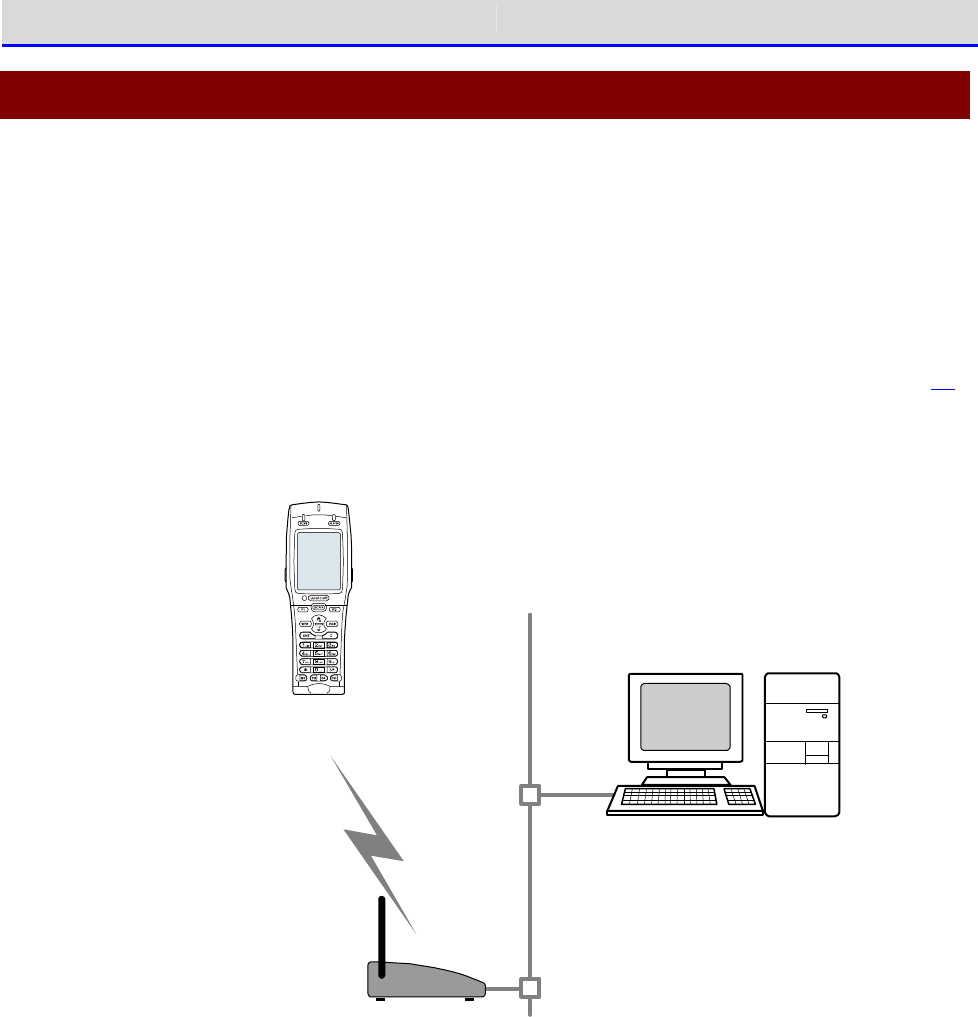
Chapter 3 Communication Environment Settings 3-1 Communication Type
GTX-221-G User’s Manual
66
3-1 Communication Type
The Handy Terminal allows you to send the entered data to a PC and to receive data from a PC.
Also, to execute any developed application software on the Handy Terminal, you will need to
transfer the software to the Handy Terminal.
The following three methods are available for connecting a PC.Prepare the communication
environment when necessary.
■WLAN Communication → "3-2 Building WLAN Communication Environment" (P.68)
You can use WLAN (wireless LAN) to perform communication with a PC via a wireless access point.
W LAN
co m m unication
LAN
Access po int
*Please use our reco m m end ed p roducts.
W ireless Two-dim ensio nal H and y Term inal
XIT-2 2 0 -G
PC having th e following software in stalled
・ W eb Glid er-X2 Ed itor packag e
(W GE-0 0 2 ): Op tio nally availab le
・ W eb Glid erInteg rated server
(W GS-0 0 1 ): Op tionally available
・ Netwo rk control too l
(Sup p lied with W GS-0 0 1)
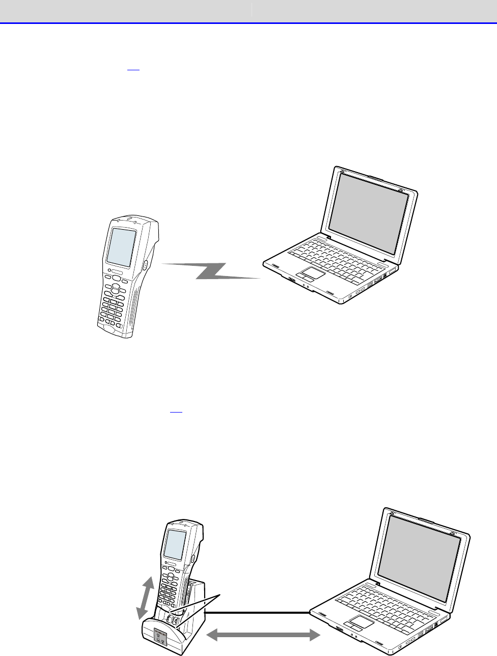
Chapter 3 Communication Environment Settings 3-1 Communication Type
GTX-221-G User’s Manual
67
■Bluetooth Communication → "3-3 Building Bluetooth Communication
Environment" (P.77)
You can send/receive files between a PC and the Handy Terminal via a Bluetooth USB adapter
connected to the PC.
This communication requires an optional transfer utility, BluePorter-V. The Bluetooth USB
adapter is supplied with the BluePorter-V Bluetooth pack (WLF-003-BT2).
Blu eto oth c om m u nicatio n
PC having the USB driver a nd
transfer utility (BluePorter-V)
installed with Bluetooth
com m u nicatio n ad ap tor.
■Infrared Communication (IrDA) → "3-4 Building Infra-red Communication
(IrDA) Environment" (P.81)
You can send/receive files to/from a PC via a USB communication unit (IU-004) or USB com-
munication/charging unit.
This communication mode requires an optional IU-004 or IU-004C, and also the transfer utility
BluePorter-V.
PC having the USB driver
and transfer utility
(BluePorter-V) installed
IrDA com m unication
between the handy
term inal and
com m unication/
charg ing unit
IrDA com m unication
port
Com m unication via the
USB cable b etween the
com m unication /
charg ing unit and PC.
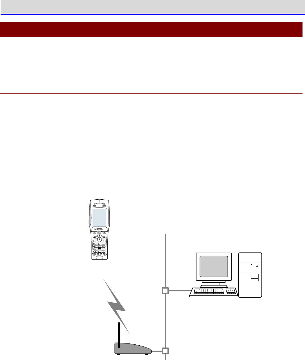
Chapter 3 Communication Environment Settings 3-2 Building WLAN Communication Environment
GTX-221-G User’s Manual
68
3-2 Building WLAN Communication Environment
To send/receive data or to download the created application software, you will need to build
an environment where WLAN communication can be executed between a PC and the Handy Terminal.
3-2-1 Preparation on the PC Side
You will need to connect a PC to the system where WLAN communication is available.
Please prepare by yourself an access point, a LAN environment, a HUB, etc.
*Please use an access point recommended by Welcat.
Install the following peripheral softwares and bring them to an operating state.
For how to install and configure the software, see the WebGlider integration server help and
the network administration tool manual.
・
·
Network Administration Tool (Integrated in WGS-001)
・WebGlider Integration Server
W LAN
co m m unication
LAN
Access po int
*Please use our reco m m end ed p roducts.
W ireless Two-dim ensio nal H and y Term inal
XIT-2 2 0 -G
PC having the following software installed
・ W eb Glid er-X2 Ed itor packag e
(W GE-0 0 2 ): Op tio nally availab le
・ W eb Glid erInteg rated server
(W GS-0 0 1 ): Op tionally available
・ Netwo rk control too l
(Sup p lied with W GS-0 0 1)
You need to connect the access point to the Ethernet LAN and configure it so that communication
with a PC is possible.
Be sure to execute the security settings. To enable security settings, you need to restart the
access point (restart may not be needed depending on the access point).

Chapter 3 Communication Environment Settings 3-2 Building WLAN Communication Environment
GTX-221-G User’s Manual
69
3-2-2 Preparation on the Product Side
To set WLAN communication for the Handy Terminal, there are the following three methods:
・Setting Wizard
・Set the respective items from the system menu
・Perform settings from a PC using the DHCP function of the network administration tool
The following information is required for WLAN configuration.
Configuration
Information
Content Remarks
SSID
SSID (or ESSID) of the access point that is the communication
partner.
Configuration
required
Security Security configuration of the access point that is the com-
munication partner.
Configuration
required
TCP/IP Address at which TCP/IP communication
is possible with a PC on
the Ethernet LAN.
Configuration
required
FTP Configured when you need to perform file transfer via WLAN
communication. Supports the FTP server of the network ad-
ministration tool supplied with the "WebGlider Integration
Server".
DNS Configured when you need to resolve names using DNS.
Whether
DNS needs to be used depends on the application software.
DHCP Configured when you need to solve the DHCP client function.
Supports the DHCP server of the network administration tool
supplied with the "WebGlider Integration Server".
Terminal ID (When using the terminal ID of the Handy Terminal)
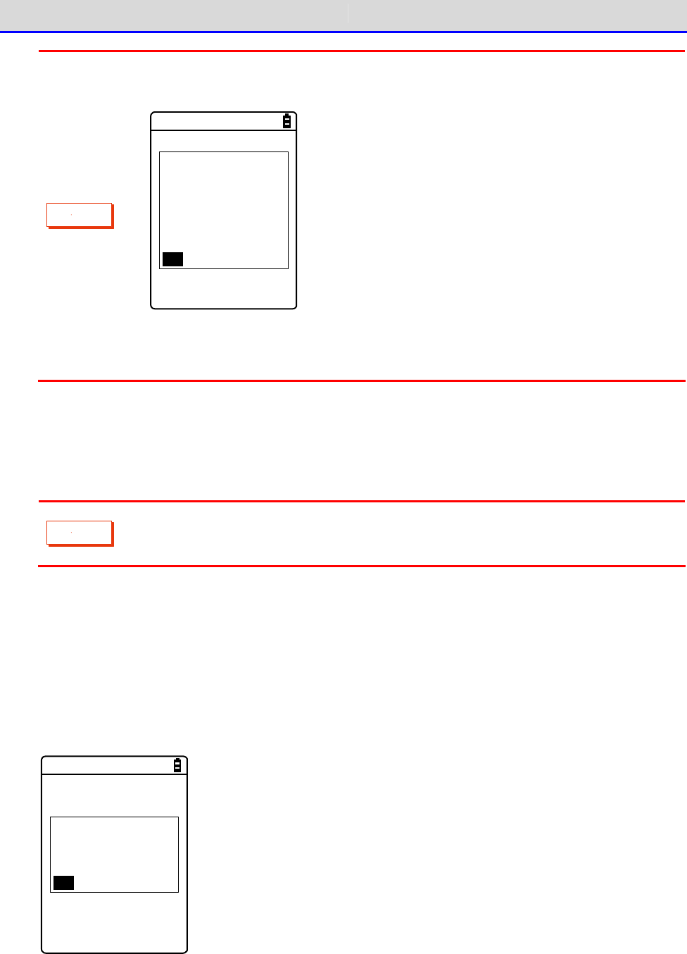
Chapter 3 Communication Environment Settings 3-2 Building WLAN Communication Environment
GTX-221-G User’s Manual
70
C
a
u
t
i
o
n
If the encryption of WLAN communication has been disabled, a dialog will be
displayed to prompt you to enable it upon startup.
Encryption system
of WLAN is invalid
, Security problem
may occur. Be sure
to get setup.
Would you like to
start setup now?
YES NO
Select[Yes]or[No].
To move to "2:WLAN", select[Yes]. Selecting[No]displays the system menu.
■WLAN Communication Settings by Setting Wizard
C
a
u
t
i
o
n
Prior to launching the setting wizard, verify that the Ethernet LAN side to which
an access point has been connected is ready for use.
At the first startup after purchasing the Handy Terminal, a setting wizard is executed for
performing the minimum required settings for WLAN communication with a PC.
If it was not set the first time, launch the setting wizard by selecting[8:Manage]-[6:Wizard].
①The setting wizard start screen is displayed.
Select[Yes] to execute the wizard.
< Wizard >
Start wizard?
Communication set-
ting can be done
with guidance
YES NO
Chapter 3 Communication Environment Settings 3-2 Building WLAN Communication Environment
GTX-221-G User’s Manual
71
②Proceed with the setting according to the screen instructions.
Be sure to perform the security configuration.
If the Handy Terminal is launched without performing the security configuration, the <WLAN
Communication Security Not Configured> prompt screen will be displayed.
For configuration items, see the next section, "Setting Wizard Flow".
③Upon completion of configuration, perform Ping test for the access point the first time.
Select[9:Test]-[1:WLAN]-[1:Configuration]on the system menu, and execute[2:WLAN/ping]
after entering the IP address of the access point.
< WLAN/ping >
Host=000.000.000.000
Time < 000.000 msec
No.00000 1472Bytes
LnkQ
CH:11
ASL
AP_MAC[000000000000]
④In the same way, perform Ping test for the IP address of the PC.
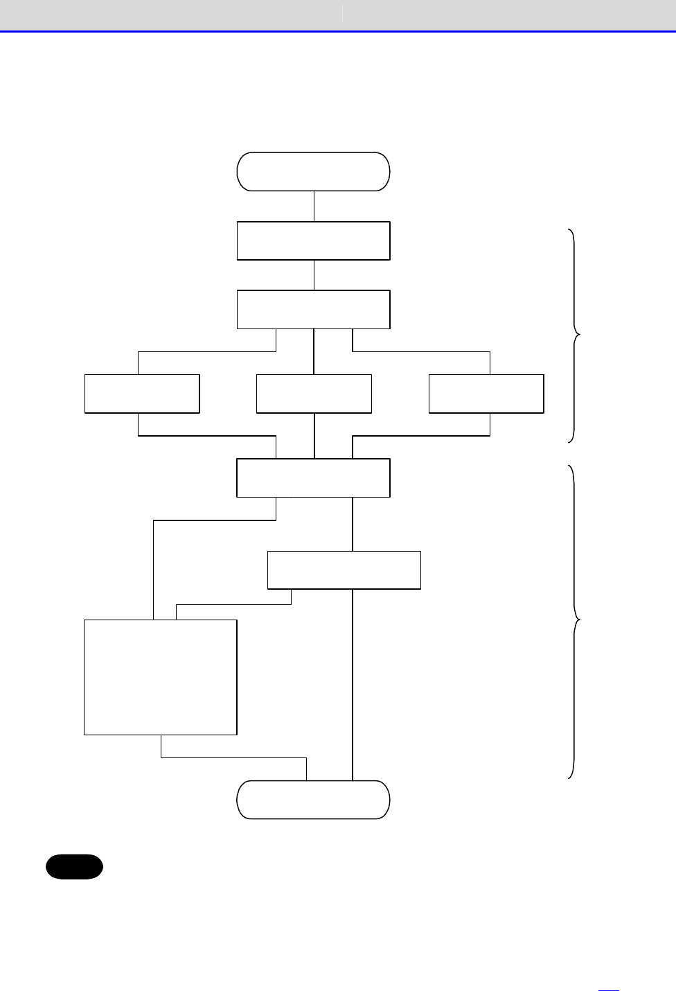
Chapter 3 Communication Environment Settings 3-2 Building WLAN Communication Environment
GTX-221-G User’s Manual
72
●Setting Wizard Flow
You need to set the items according to the flow shown in the following figure in the setting
wizard. The setting items vary according to your selections during the process.
W izard
SSID
En cryp tion system
W EP key 1 ~4
TxKey ID Pre-sh ared key
To ind icate the caution
that the encryption
system is being disabled .
DH CP
Run DH CP
System m en u
IP ad d ress
Sub n et m ask
Defa ult g ateway
FTP server
DNS server
Term inal ID
W h en an ap p licatio n is booted u p ,
W h en the system m enu is shown ,
TKIP or
CCM P(AES)
W EPDisab le
Disab le
Success in
setting up
the netwo rk
Failu re in
setting up
the n etw ork
W LA N
TCP/IP
Hint
・Returns to the system menu without executing DHCP if the wizard was executed
from the system menu.
・WLAN communication's authentication method cannot be set in the wizard. Perform
the setting manually due to the complexity, especially in EAP certification
where reception of files including certificates is required.
For manual setting, see "4-4
WLAN: WLAN Communication Settings
" (P.114).
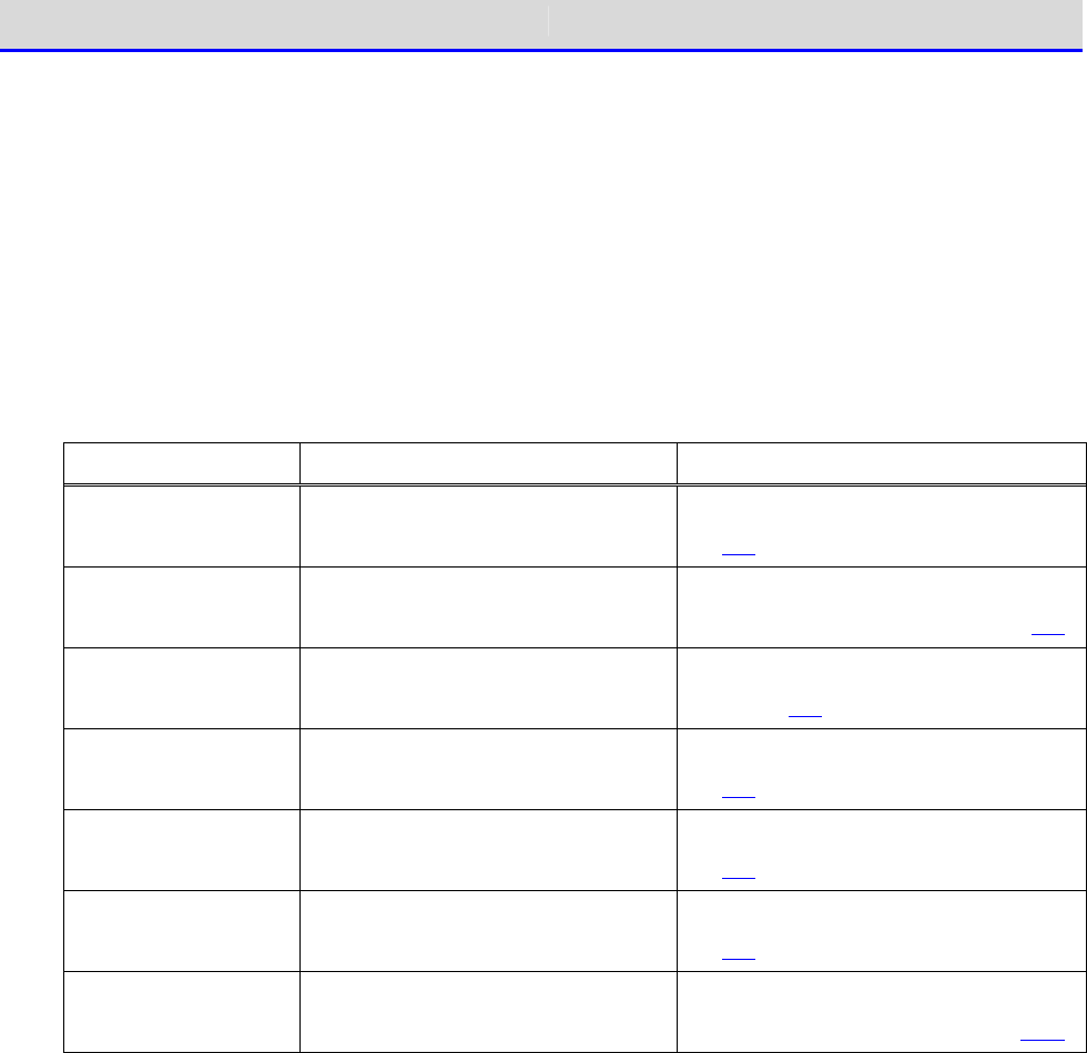
Chapter 3 Communication Environment Settings 3-2 Building WLAN Communication Environment
GTX-221-G User’s Manual
73
■WLAN Communication Settings by the System Menu
You can set the required items individually from the system menu.
Perform the setting using the following procedure:
①Launch the system menu.
②Set the required items with reference to the following table.
③Perform Ping test and verify the communication state.
Item System Menu Reference page
SSID Configuration [2:WLAN]-[1:SSID] "3-4-1 SSID: SSID Configuration"
(P.114)
Security
Configuration
[2:WLAN]-[4:Security] "3-4-4 Security: WLAN Communica-
tion Security Configuration" (P.116)
TCP/IP
Configuration
[3:Network]-[1:TCP/IP] "3-5-1 TCP IP: TCP/IP Configura-
tion" (P.131)
DHCP Configuration [3:Network]-[2:DHCP] "3-5-2 DHCP: DHCP Configuration"
(P.133)
FTP Configuration <3:Network> <3:FTP> "3-5-3 FTP: FTP Configuration"
(P.136)
DNS Configuration [3:Network]-[4:DNS] "3-5-4 DNS: DNS Configuration"
(P.140)
Terminal ID
Configuration
<6:Terminal ID> "4-8
Terminal ID: Configure the ID
for Terminal Identification" (P.162)
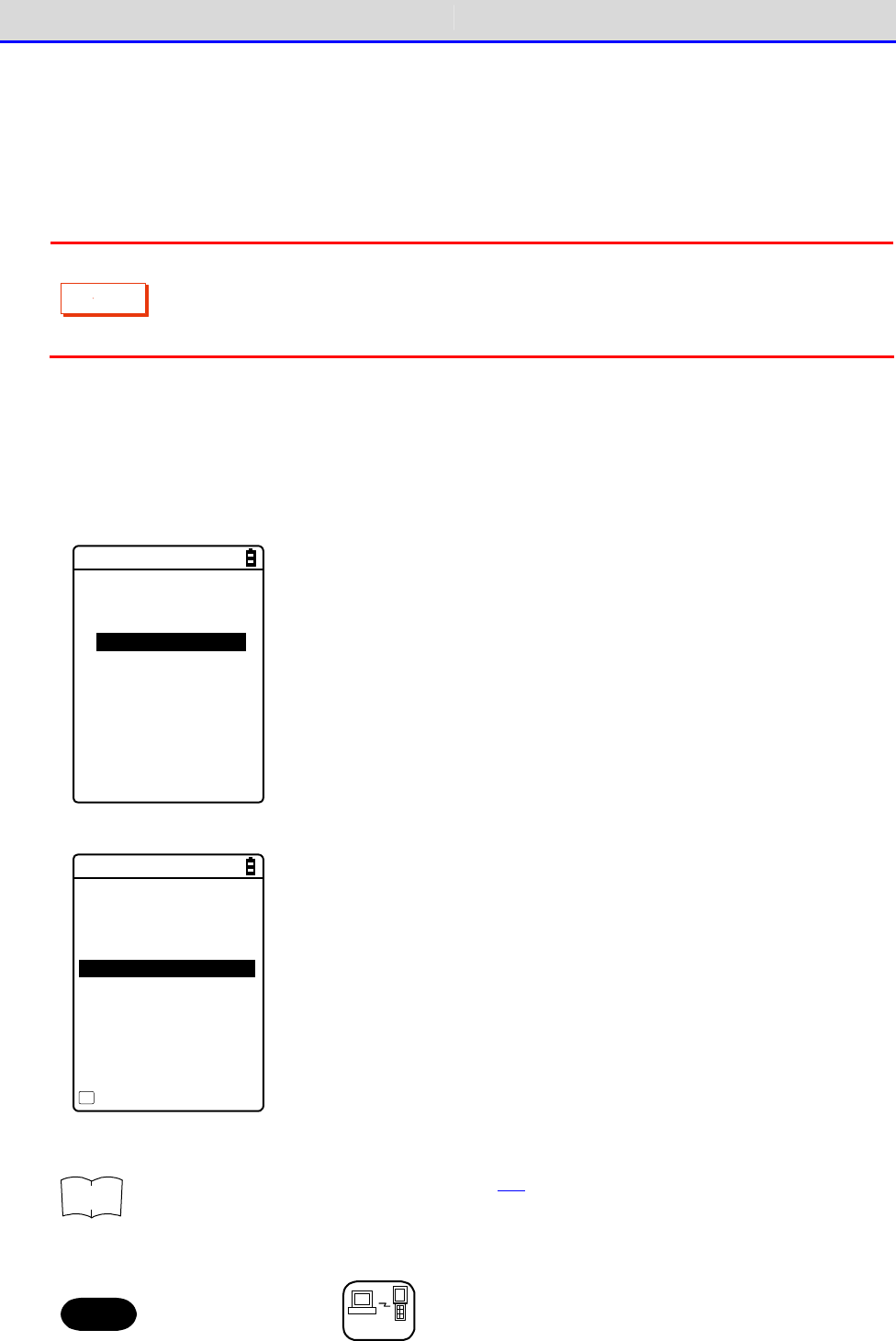
Chapter 3 Communication Environment Settings 3-2 Building WLAN Communication Environment
GTX-221-G User’s Manual
74
■WLAN Communication Settings by DHCP
You can configure the required items collectively on the PC side using the DHCP client function.
When using the DHCP client function, you need "Network Administration Tool", which is separately
supplied with "WebGlider Integration Server".
C
a
u
t
i
o
n
Configuring "SSID Configuration" and "Security Configuration" items using the
DHCP client function may generate security vulnerability. Avoid using it to the
extent possible.
To enable the DHCP function, perform the following configurations on the system menu:
①[3:Network]-[2:DHCP]-[Startup type]
②Select[Application boot].
< Startup type >
Disabled
Application boot
System menu boot
Auto wake up boot
③Configure the port number of the DHCP server.
< DHCP >
1:Startup type
2:Item not to Update
3:Server port
[08067]
Execute
F1
r
rr
re
ee
ef
ff
f
See "4-5-2 DHCP: DHCP Settings" (P.133) and "WebGlider Integration Server
WGS-001 Manual".
Hint
This manual has a
DHCP
mark for items that can be configured by DHCP.
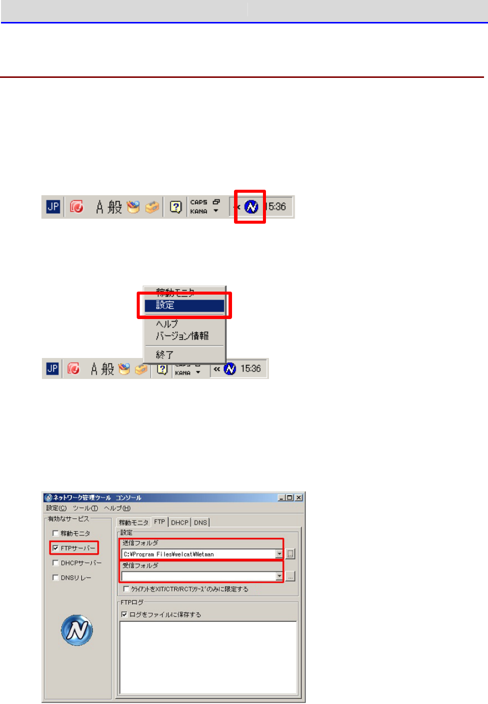
Chapter 3 Communication Environment Settings 3-2 Building WLAN Communication Environment
GTX-221-G User’s Manual
75
3-2-3 Downloading the Application Software by
WLAN Communication
After the WLAN communication environment is ready, you can download the files according to the
following procedure:
①Launch the network administration tool on the PC.
After the network administration tool is launched, its icon is displayed in the task tray
of the PC.
②Right-click the icon of the network administration tool, and then click [Set](設定) from
the displayed menu.
③On the network administration tool configuration screen, click the [FTP] tab, and then perform
the following configuration:
・Select the [FTP server](FTP サーバー) checkbox.
・[Transmit folder](送信フォルダ) and [Receive folder](受信フォルダ) specify the folders
on the FTP server where the application software file is located.
④Select [4:Receive]-[1:WLAN]on the system menu.
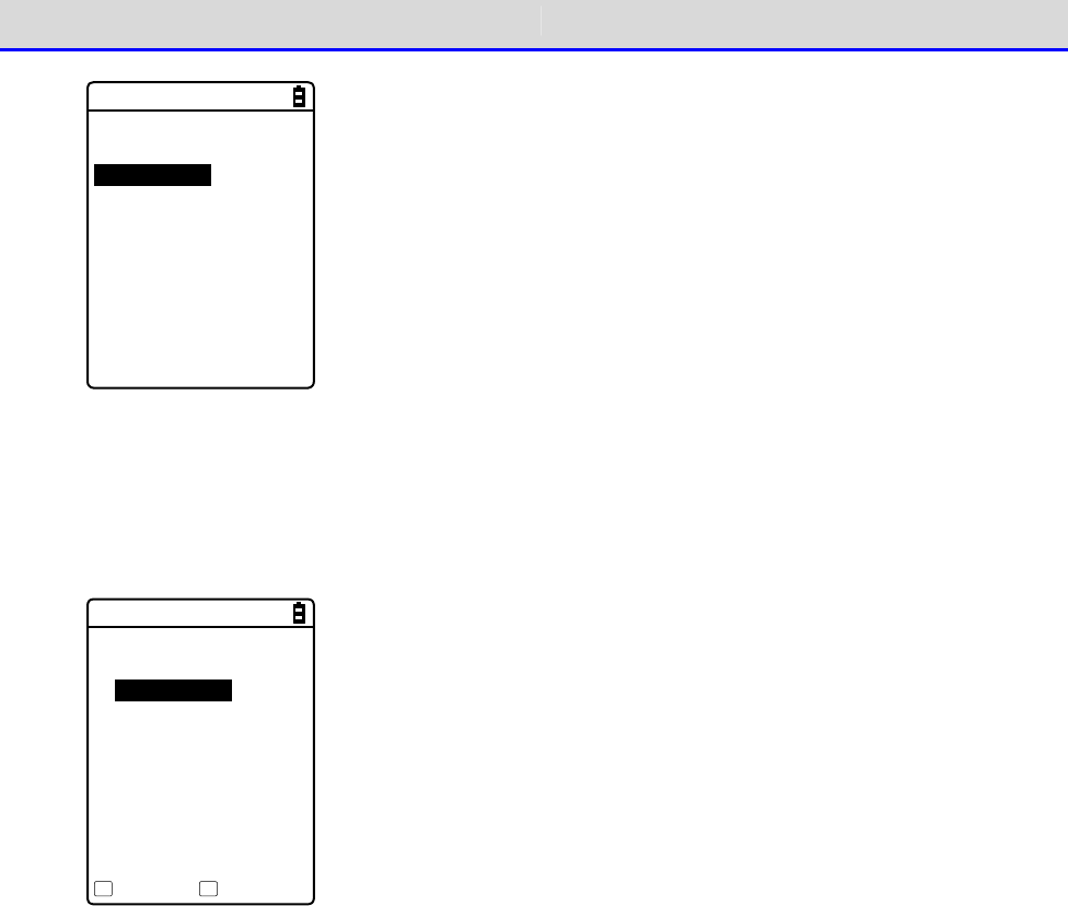
Chapter 3 Communication Environment Settings 3-2 Building WLAN Communication Environment
GTX-221-G User’s Manual
76
< Device type >
1:WLAN
2:Bluetooth
3:IrDA
⑤The list of downloadable files is displayed.
Select the files to be downloaded by checking their names.
Press the【F1】key to start the download.When the confirmation prompt is displayed, select
[Yes] and then press the【ENT】key. Downloading a large file may take long time.
< File list >
SAMPLE1.OUT
SAMPLE2.OUT
Receive Menu
F1 F2
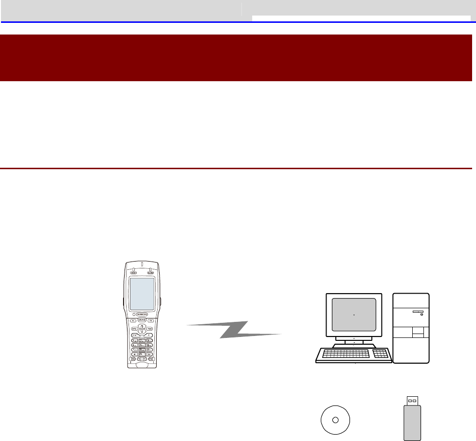
Chapter 3 Communication Environment Settings 3-3 Building Bluetooth Communication
GTX-221-G User’s Manual
77
3-3 Building Bluetooth Communication
Environment
To send/receive data or to download the created application software, you need to build an
environment where Bluetooth communication can be executed between a PC and the Handy Terminal.
3-3-1 Preparation on the PC Side
Install the following peripheral softwares and bring them to an operating state.
For how to install and configure the softwares, see the BluePorter-V operation guide.
・Transfer Utility BluePorter-V
・Bluetooth Communication Adapter Driver Software
↑ ↑
W ireless Two-dim ensio nal H and y Term inal
XIT-2 2 0 -G
Bluetoo th co m m unication
Transfer utility
BluePorter-V Bluetooth
com m unicatio n
ad ap tor
■COM Port Verification
You will need to verify the COM port to which the Bluetooth communication adapter has been
connected.
For how to verify the COM port, see the BluePorter-V operation guide.
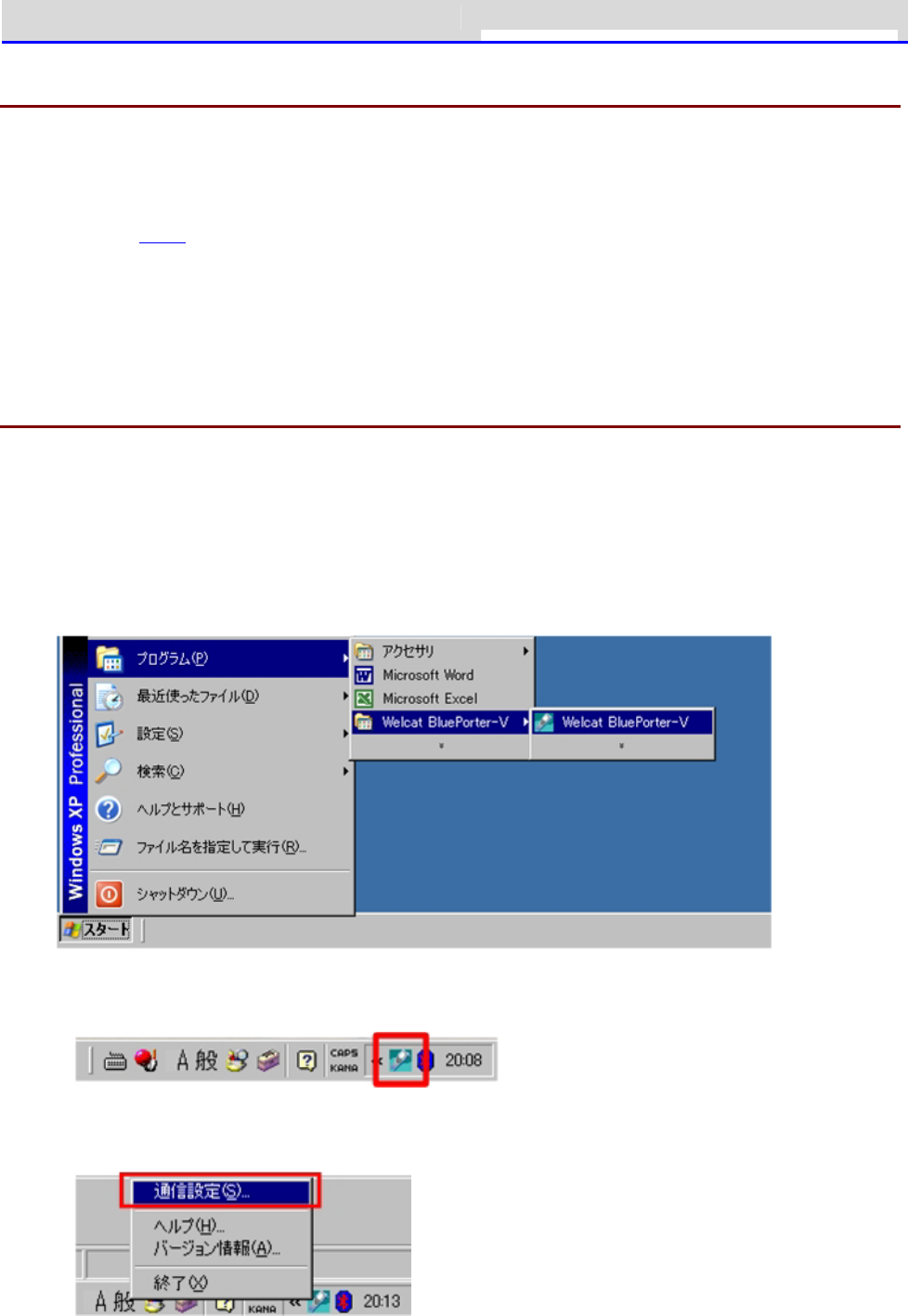
Chapter 3 Communication Environment Settings 3-3 Building Bluetooth Communication
GTX-221-G User’s Manual
78
3-3-2 Preparation on the Product Side
To perform Bluetooth communication with the Handy Terminal, you will need to search for the
Handy Terminal from the PC side and register it in advance using device registration.
For device registration method, see "4-9-3 Bluetooth: Registering and Setting the Bluetooth
Device" (P.169).
For how to verify the BD address of the Bluetooth communication adapter, see the BluePorter-V
operation guide.
3-3-3 Downloading the Application Software by
Bluetooth Communication
After the Bluetooth communication environment is ready, you can download your files according
to the following procedure:
①To launch the transfer utility BluePorter-V on your PC,
Click [Start](スタート)-[Program](プログラム)-[Welcat BluePorter-V]-[Welcat
BluePorter-V].
②Right-click the icon of the transfer utility BluePorter-V displayed in the task tray.
③Click[Communication setting](通信設定)from the displayed menu.
④Set[COM Port No. to Use](使用する COM ポート番号)to the desired COM port number.
[Receive folder](受信フォルダ)and[Transmit folder](送信フォルダ)specify the folders
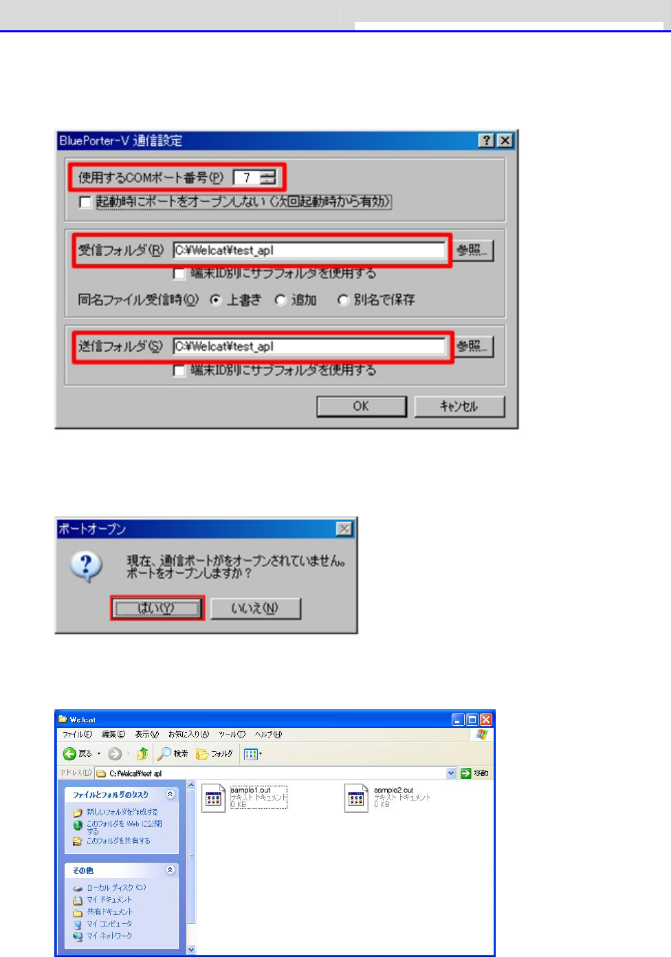
Chapter 3 Communication Environment Settings 3-3 Building Bluetooth Communication
GTX-221-G User’s Manual
79
where the application software file is located.
The following figure shows an example where the application software is located in the
"C:\Welcat\test_apl" folder.
⑤Press the [OK] button to close the window.
After the following screen appears, click [Yes](はい).
⑥Copy the execution file of the application software to the folder set as the transmission
folder of BluePorter-V("C:\Welcat\test_apl" in the above example).
⑦Select [4:Receive]-[2:Bluetooth] on the system menu.
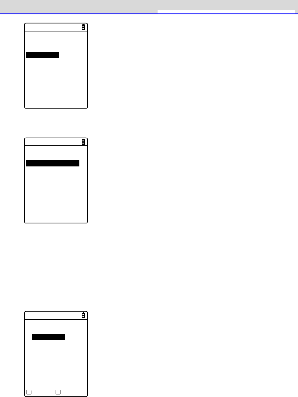
Chapter 3 Communication Environment Settings 3-3 Building Bluetooth Communication
GTX-221-G User’s Manual
80
< Device type >
1:WLAN
2:Bluetooth
3:IrDA
⑧Select [1:Select from list].
< Receiving method >
1:Select from list
2:wait(PC)
3:wait(HT)
⑨The Handy Terminal automatically logs in BluePorter-V, displaying the list of downloadable
files.
Select the files to be downloaded by checking their names.
Pressing the【F1】Key displays the confirmation message box.Move your mouse over [Yes] and
then press the【ENT】key to start download. It will take from several seconds to several minutes
to complete.
However, downloading a large file may take long time.
< File list >
SAMPLE1.OUT
SAMPLE2.OUT
Receive Menu
F1 F2
Chapter 3 Communication Environment Settings 3-4 Building Infra-red Communication (IrDA)
GTX-221-G User’s Manual
81
3-4 Building Infra-red Communication (IrDA) En-
vironment
To transfer files via infrared communication, the following optional equipment and softwares
are required.
・USB Communication Unit (IU-004) or USB Communication/Charging Unit (IU-004C)
・USB Driver Software (Included in the Product Manual CD-ROM)
・Transfer Utility Software (BluePorter-V)
Hint
The explanations in this manual are examples for Windows XP, Vista, and 7.The
screen may vary in other versions.
C
a
u
t
i
o
n
The error that the COM port cannot be enabled may occur when the WL7-USB dedicated
software "WL7-KEY" is used by customers who use Welcat cordless Handy Terminal
set, WL7-USB.If WL7-KEY is Ver 1.02 or lower, as the COM port has been occupied,
it cannot be enabled.
In such a case, please contact your dealer.
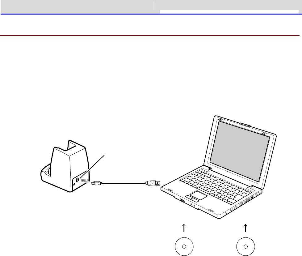
Chapter 3 Communication Environment Settings 3-4 Building Infra-red Communication (IrDA)
GTX-221-G User’s Manual
82
3-4-1 Preparation on the PC Side
You can connect the USB communication unit and the host computer by using a USB cable.
Install the following peripheral softwares and bring them to an operating state.
・Transfer Utility Software (BluePorter-V)
・IU-004/IU-004C's Driver Software
For installation and the setting procedures, see the user manuals of the respective products.
USB p ort
USB cab le
Tran sfer utility
BluePorter-V
M anual CD
IU-0 0 4 /0 0 4 C
Driver So ftware
Chapter 3 Communication Environment Settings 3-4 Building Infra-red Communication (IrDA)
GTX-221-G User’s Manual
83
3-4-2 Downloading the Application Software by Infrared Com-
munication (IrDA)
After the infrared communication environment is ready, you can download your files according
to the following procedure.
■Equipment Preparation
Prepare the following equipment and software.
・The Product
・Transfer Utility (BluePorter-V)
・USB Communication Unit (IU-004/IU-004C)
■Preparation before Use
①Install the transfer utility BluePorter-V in your PC.
②Install the USB driver of the USB communication unit in the host computer.
* For how to install the USB driver, see "3-4 Building Infra-red Communication (IrDA)
Environment" (P.81).
●When Launching the Setting Wizard
At the first startup after purchasing the Handy Terminal, a setting wizard is executed for
performing the minimum required settings for Bluetooth communication with a PC.
This wizard is not required in infrared communication mode.
Selecting[No]on the wizard screen launches the system menu.
To perform Bluetooth communication, start the wizard with reference of "4-10-6 Wizard: Starting
the Screen Facilitating Configuration of Communication Settings" (P.197) and make the settings.
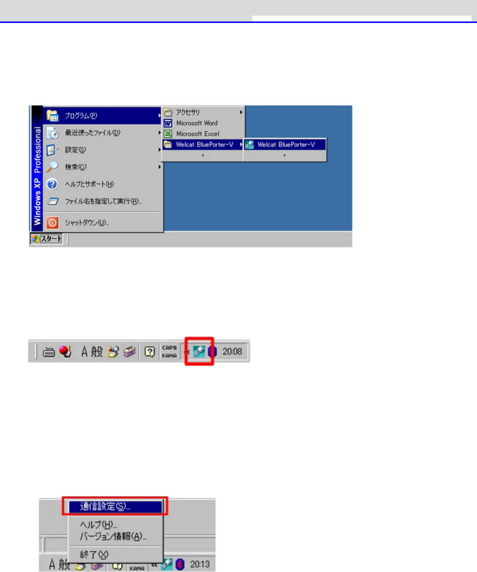
Chapter 3 Communication Environment Settings 3-4 Building Infra-red Communication (IrDA)
GTX-221-G User’s Manual
84
■Transfer Utility BluePorter-V Startup
To launch the transfer utility BluePorter-V,
Click[Start](スタート)- [Program](プログラム) -[Welcat BluePorter-V].
After it is launched, its icon is displayed in the task tray.
Right-click the displayed "BluePorter-V" icon, and then click[Communication setting]on the
displayed menu.
■Communication Settings
You can set the transmission folder, the reception folder and the COM port to use.
①Right-click the icon displayed in the task tray, and then click the[Communication setting]
(通信設定)on the displayed menu.
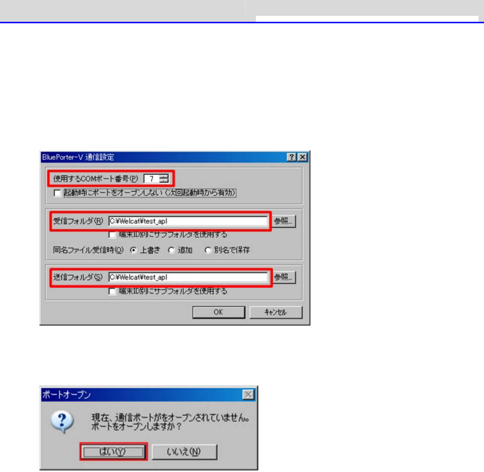
Chapter 3 Communication Environment Settings 3-4 Building Infra-red Communication (IrDA)
GTX-221-G User’s Manual
85
②Set[COM Port No. to Use](使用する COM ポート番号)to the COM port number using the device
manager .
For how to verify the COM port number, see the user manual of IU-004/IU-004C.
[Receive folder](受信フォルダ)and [Transmit folder](送信フォルダ) specify the folders
where the application software file is located.
The following figure shows an example where the application software is located in the
"C:\Welcat\test_apl" folder.
③Press the[Yes]button to close the window.
When the following screen appears, click[Yes](はい).
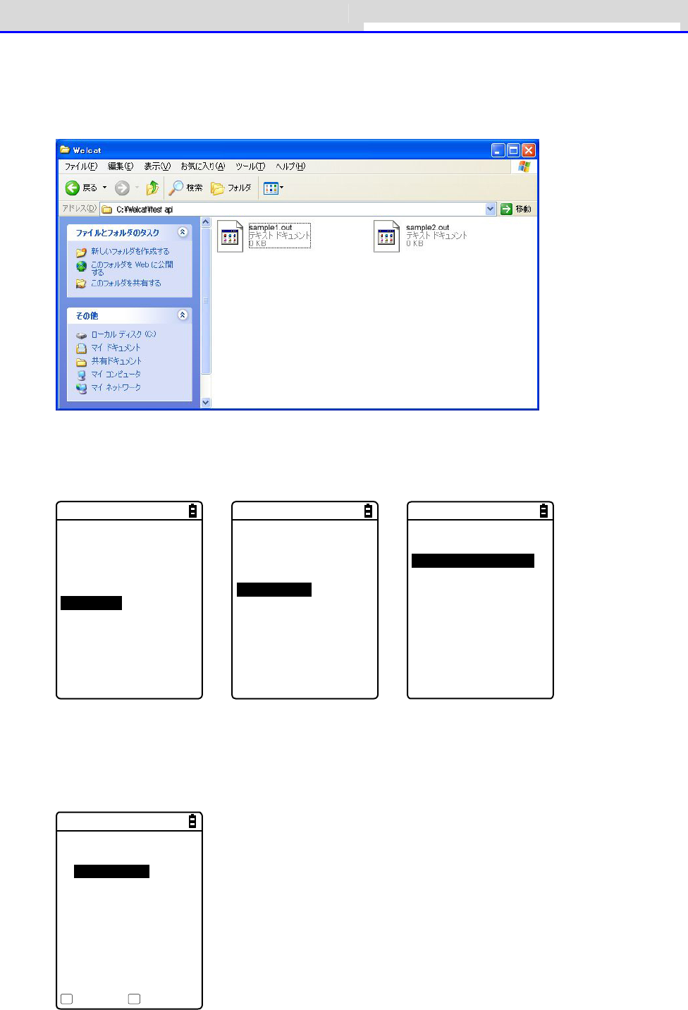
Chapter 3 Communication Environment Settings 3-4 Building Infra-red Communication (IrDA)
GTX-221-G User’s Manual
86
■File Download
①Copy the execution file of the application software to the folder set as the transmission
folder of BluePorter-V ("C:\Welcat\test_apl" in the above example).
②Next, launch the system menu.
On the system menu, select [2:Receive]-[3:IrDA]-[1:Select from list].
< System menu >
1:System 6:ID
2:WLAN 7:Device
3:Network 8:Manage
4:Receive 9:Test
5:File
→
< Device type >
1:WLAN
2:Bluetooth
3:IrDA
→
< Receiving method >
1:Select from list
2:Wait(HT)
③The Handy Terminal automatically logs in BluePorter-V, displaying the list of downloadable
files.
Select the files to be downloaded by checking their names.
< File list >
SAMPLE1.OUT
SAMPLE2.OUT
Execute Menu
F1 F2

Chapter 3 Communication Environment Settings 3-4 Building Infra-red Communication (IrDA)
GTX-221-G User’s Manual
87
④Set the Handy Terminal to the USB communication unit.
Pressing the【F1】key displays the[Would you like to receive it?] screen.Select[Yes]and
then press the【ENT】Key to start download. It will take from several seconds to several minutes
to complete.
However, downloading a large file may take long time.
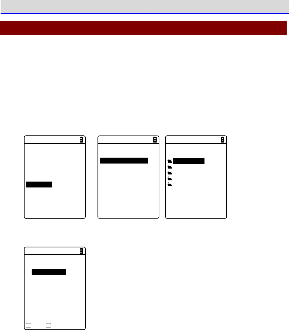
Chapter 3 Communication Environment Settings 3-5 Executing the Application Software
GTX-221-G User’s Manual
88
3-5 Executing the Application Software
Once the downloaded application software (file extension=OUT) is received into the Handy
Terminal, its installation is complete and it is ready for execution.
■Selecting from the File List to Execute
If multiple application softwares have been installed, you can select the files from the file
list and execute them.
①Select[5:File]- <Select drive> -[1:Application]on the system menu.
< System menu >
1:System 6:ID
2:WLAN 7:Device
3:Network 8:Manage
4:Receive 9:Test
5:File
→
< Drive type >
1:FDrive
2:SDrive
3:RDrive(microSD)
→
< File type >
Application
Data
Audio
Graphic
All type
②Select the application software and then press the【F1】key
< FDrive >
WGX2BRWS.OUT
Menu SDrive
F1 F2
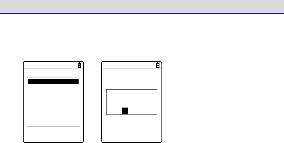
Chapter 3 Communication Environment Settings 3-5 Executing the Application Software
GTX-221-G User’s Manual
89
③From the popup menu, select [Execute], and then press the【ENT】key.
The < Execute> screen is displayed and the confirmation query on registration to the
automatic execution program is displayed. To perform automatic execution select[Yes],
otherwise select[No], and then press the【ENT】key.
Execute
Properties
Upload
Delete
All checks applied
All checks removed
Copy to SDrive
Copy to RDrive
→
Would you like to
register with
“Auto execute”?
YES NO
The application software is launched.
For how to use the respective application softwares, see the operation instruction manual and
other manuals prepared by the application software developer or the system administrator. The
application software is basically terminated by pressing the【PW】key. However, this may not
apply to all application softwares.
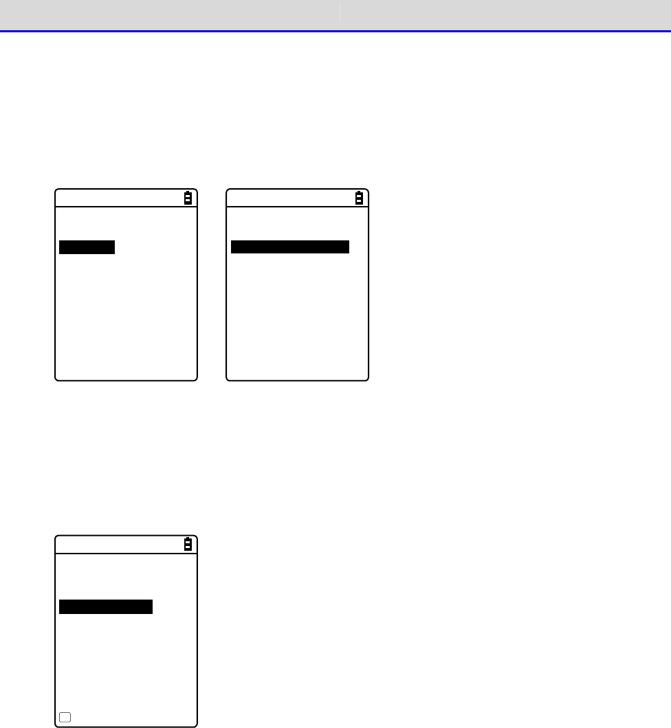
Chapter 3 Communication Environment Settings 3-5 Executing the Application Software
GTX-221-G User’s Manual
90
■Automatic Execution upon Startup
You can automatically execute the application software without launching the system menu during
startup of the Handy Terminal.
①Select[1:System]-[1:Auto execute] in the system menu.
< System menu >
1:System 6:ID
2:WLAN 7:Device
3:Network 8:Manage
4:Receive 9:Test
5:File
→
< System setting >
1:Auto execute
2:Clock
3:Power management
4:Password
②Select the file name to execute from the list of installed application softwares, and then
press the【ENT】Key to return to the <System setting> screen. This completes registration
of the automatic execution file.
When the power is turned on the next time, the registered application software is launched.
The system menu is launched if it has been set for automatic execution.
< Auto execute >
System menu
WGX2BRWS.OUT
Property
F1

Chapter
4
System Menu
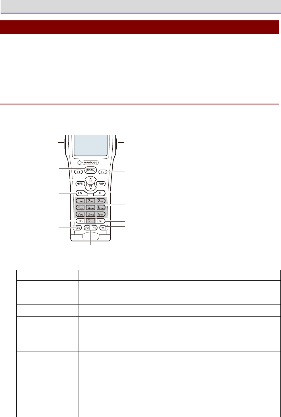
Chapter 4 System Menu 4-1 Using the System Menu
GTX-221-G User’s Manual
92
4-1 Using the System Menu
As a part of the functions available in the system programs, the system menu provides various
functions, such as environment settings, platform for the application software. You can use
the Handy Terminal more efficiently if you perform your settings according to your operating
environment.
4-1-1 Operation Keys
This section describes the function of each key.
Function key
Function key
A
rrow key (F5~F8)
ENT key C key
BS key
Ten key
Dot ( .) key
PW key
SCAN key
SF key
Trig g er key Trig g er key
Key Function
【SCAN】key Used for reading a barcode.
【ENT】key Confirms the selected operation.
【C】key
Returns to the immediately previous status, or deletes the character entered.
【BS】key Deletes one character from the characters entered.
【SF】key Switches the character input mode.
【F1】
–
【F8】keys Execute the respective functions (special features).
Arrow keys Perform cursor operations.
If【
⊳
F5】【
F6】【
F7】【
F8】are specified, F5
–
F8 are assigned to
the respective arrow keys.They are used in libraries, etc.
Trigger keys Used for reading a barcode.
The【F9】and【F10】keys are respectively assigned to the two trigger keys.
【PW】key Used to turn the power on/off.
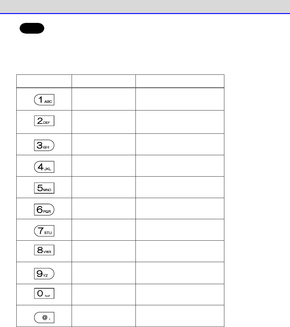
Chapter 4 System Menu 4-1 Using the System Menu
GTX-221-G User’s Manual
93
Hint
In this manual, the names of keys are shown enclosed within【 】.
(Ex.)【1】key,【F2】key,【ENT】key
■List of Key Assignments
Key
Numeric Input Mode
Alphabetic Input Mode
1 A B C
2 D E F
3 G H I
4 J K L
5 M N O
6 P Q R
7 S T U
8 V W X
9 Y Z
0 S p a c e
.(dot) * $ - + / % : # @ &
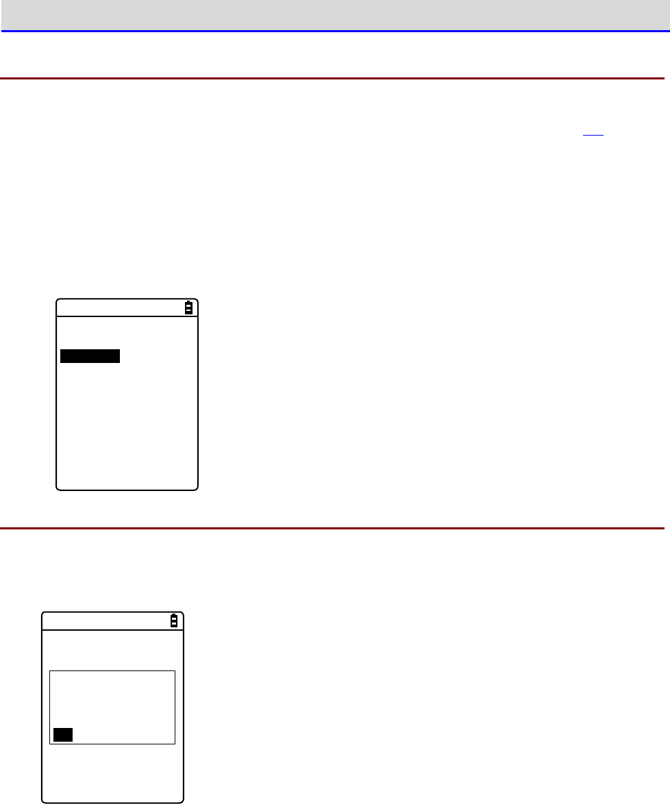
Chapter 4 System Menu 4-1 Using the System Menu
GTX-221-G User’s Manual
94
4-1-2 Launching the System Menu
By default settings, the system menu is launched when you power on the Handy Terminal.
If the application software has been selected in the automatic execution program (P.103), launch
the system menu using the following operations:
①In the power OFF state, press the【PW】key for about one second while holding down the【SCAN】
key.
The system menu is launched when the power is turned on.
②After the opening screen is displayed, the system menu appears.
< System menu >
1:System 6:ID
2:WLAN 7:Device
3:Network 8:Manage
4:Receive 9:Test
5:File
4-1-3 When Launching the System Menu for the First Time
When you start the Handy Terminal for the first time after purchasing it, the setting wizard
is executed to allow you to perform the minimum required settings for WLAN communication between
the server and the Handy Terminal.
< Wizard >
Start wizard?
Communication set-
ting can be done
with guidance
YES NO
•
Select [Yes] to execute the wizard where you perform WLAN communication settings.
•
Selecting [No] launches the system menu.
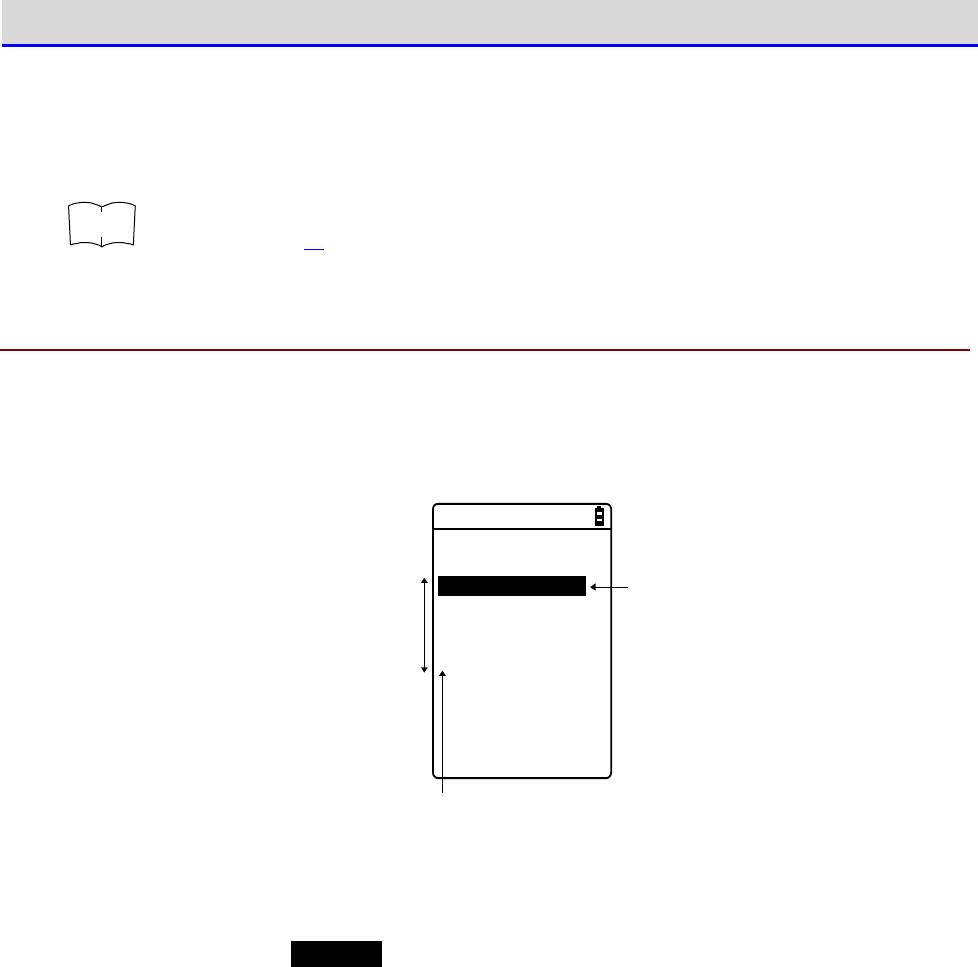
Chapter 4 System Menu 4-1 Using the System Menu
GTX-221-G User’s Manual
95
Select [No] to skip the setting wizard, or execute the setting wizard till you complete all
the settings to avoid launching the setting wizard at the next startup.
r
rr
re
ee
ef
ff
f
For how to use the setting wizard, see "■WLAN Communication Settings by Setting
Wizard" (P.70).
4-1-4 Using the System Menu
This section describes the basic operations of the system menu.
■Selecting Setting Items
< System setting >
1:Auto execute
2:Clock
3:Power management
4:Password
An item being
selected is
highlighted.
Can directly select an item you want simply
by pressing the number of that item.
Can move from
one item to other
with the directional
key (⊳,,,).
●Select an Item
The selected item is
highlighted
.
Press the key from【0】
–
【9】that corresponds to the respective item, or use the arrow keys
(【
】,【
】) to move the highlighted display.
●Confirm the Item Selection
Press the【ENT】key to confirm the item selection.
The operations after the confirmation vary depending on the items.
•
Execute the selected function
•
Select one of the two options:[Yes] or[No] (button)
•
Display its submenu
●Cancel Your Selection
Press the【C】key to return to the immediately previous operation.
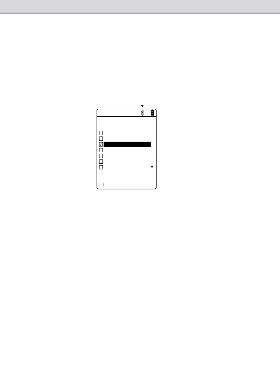
Chapter 4 System Menu 4-1 Using the System Menu
GTX-221-G User’s Manual
96
●About Screen Display
If the menu items cannot be accommodated in one screen, the scroll icon will be displayed
in the status bar at the top of the screen. Also, if the full item name cannot be accommodated
in one row, the name will be cut short at the end and followed by "
→
".
< FDrive >
1/1
123X128.JPG
COPAN1.JPG
SAMPLE1.OUT
SAMPLE2.OUT
HABANERO.JPG
LONG_FILE_NAME_AA
MAKE.TXT
Menu
F1
Scroll icon
Either the Up , Down or Up /Down icon is shown that
is availab le resp ectively in an in divid u al wind o w.
An arrow, "" at the end of an item n am e ind icates
that there are som e rem aining p arts of the nam e
no t sh own in the window.
■Entering Data Using Keys.
You can enter characters using the numeric keypad and the【SF】key.
Numerals, alphabets (upper case / lower case) and symbols can be entered.
●Switch the Character Input Mode
Press the【SF】key to switch the input mode.
*1
Numeric Input
Mode:
You can enter numerals and the decimal point in
this mode.
The "1" icon is displayed in the status bar.
Alphabetic Input
Mode:
Alphabets (upper case / lower case), numerals
and symbols can be entered.
The "A" icon is displayed in the status bar.
●Enter Numerals
Press the【SF】key to switch to the numeric input mode (cursor: (underline)).
Keys that can be used:【0】
–
【9】keys

Chapter 4 System Menu 4-1 Using the System Menu
GTX-221-G User’s Manual
97
●Enter Alphabets
Press the【SF】key to switch to the alphabetic input mode (cursor:■(rectangle).
Keys that can be used:【2】
–
【9】keys
•
When entering alphabets that are assigned to the same key, press the【
】key to move
the cursor, and then enter the next alphabet.
•
Press the【
】/【
▼
】key to toggle between upper case and lower case for the alphabet
at the cursor position.
*2
●Enter Symbols
Press the【SF】key to switch to the alphabetic input mode (cursor:■(rectangle).
Key that can be used:【0】key
•
When entering symbols that are assigned to the same key, press the【
】key to move the
cursor, and then enter the next symbol.
•
If you press the【
】key when the cursor is located at the end of the entered data string,
a space will be inserted to the right of the cursor.
*2
●Confirm the Data Entered
Press the【ENT】key.
●Delete Characters
*3
•
Press the【BS】key to delete the character at the location of the cursor.
•
Press the【C】key to delete all the entered characters.
●Cancel the Entry
•
For items where you cannot delete the characters
*3
, press the【C】key to immediately
stop your entry.
•
For items where you can delete the characters, press the【C】key after deleting all the
characters entered.
●Other
When the number of characters exceeds the entry limit, the cursor will return to the starting
point.
*1 For items that have restrictions on the types of characters that can be entered (e.g.,
only numerals for terminal ID), the input mode cannot be switched.
*2 The number of characters you can enter may vary depending on the items.
*3 You cannot delete characters on items that have a fixed entry format (e.g., local BD
address).This manual uses the following delete-disabled icon for items with a fixed entry
format.
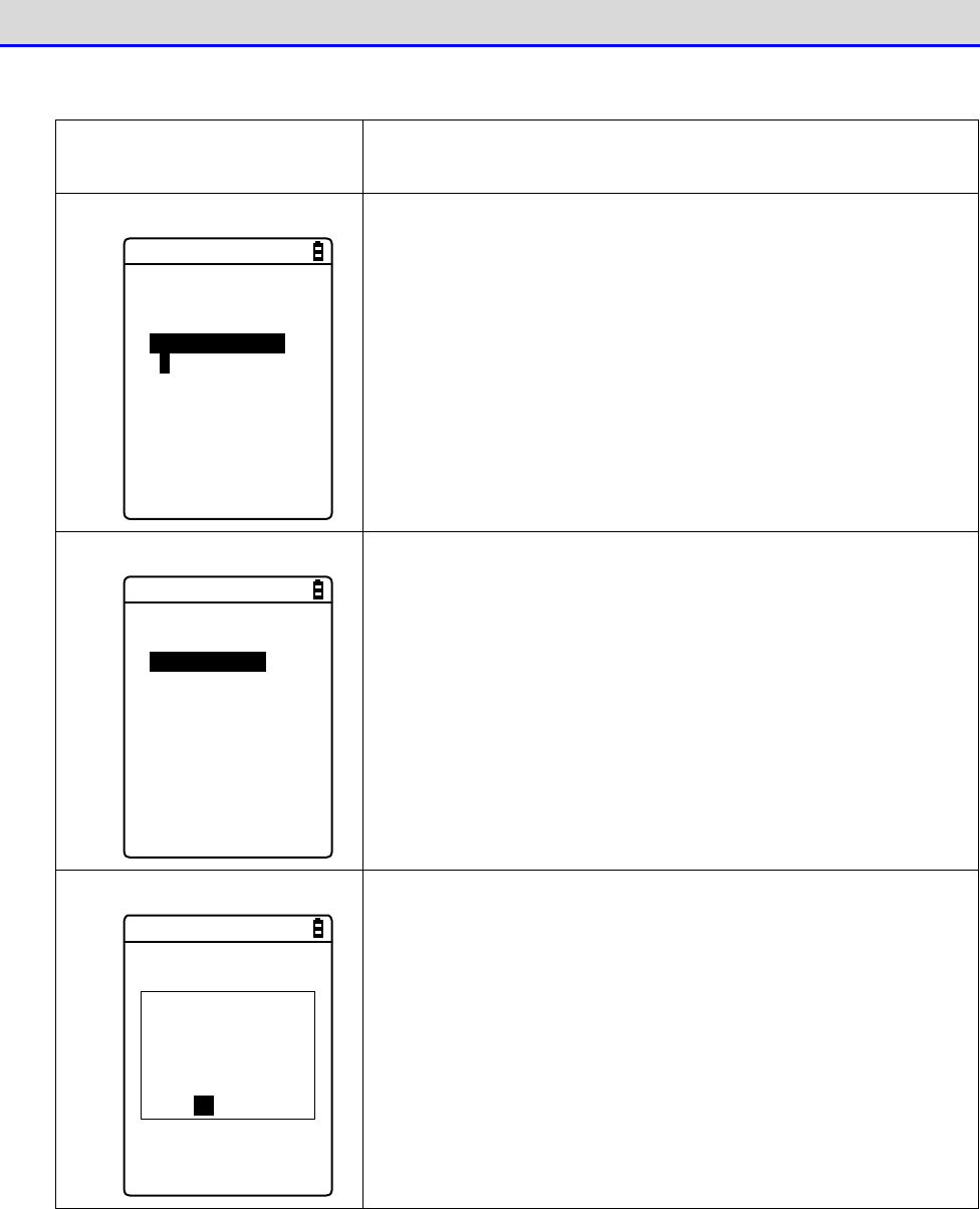
Chapter 4 System Menu 4-1 Using the System Menu
GTX-221-G User’s Manual
98
■Other Operations
Returning to the Immediately
Previous Status
【C】key
Checkbox
< Security >
Pairing Enable
PIN code
[ ]
Select the item, and press the【ENT】key to toggle between
Selected and Cleared.
A check mark is attached to the selected box.
Checkboxes are used for selecting multiple items at a time.
Radio Button
< Click Sound >
None
Beep
Beep + Audio
Audio
Select the item, and press the【ENT】key to change the item
selected.
The item with a filled circle indicates that it is currently
enabled.
The radio button is used when only one item is to be selected
from multiple items.
Message Box
The remote has
been already
registered.
Would you like to
overwrite it?
YES NO
When two buttons, such as[Yes]and[No], are displayed, press
either the【1】or the【2】key, or use the arrow keys (【
】,
【
▼
】,【
⊳
】,or【
】) to select your desired button
(highlighted), and then press the【ENT】key to confirm.
Press the【C】key to select the button on the right.
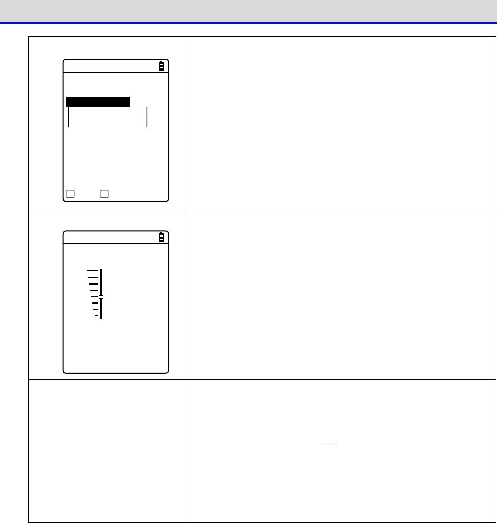
Chapter 4 System Menu 4-1 Using the System Menu
GTX-221-G User’s Manual
99
Calling the Submenu
< Prooerty >
1:Device name
XIT-220
2:BD Address
[00:03:7A:0B:0A:AB]
3:Security
Save Search
F1 F2
While [F1] or [F2] is displayed at the bottom of the screen,
press the corresponding key to display its submenu or to execute
its function (special feature).
Slider
< Volume >
F6(Up)
Level : 4
F7(Down)
Use the【
▲
】【
▼
】keys to move the slider for performing the
setting.
Indicator Change during Op-
eration
You can change the indicator (buzzer/vibrator/LED) that works
during operation according your individual settings. For its
change method, see "4-9-5 Tone/Vibrator: Setting the Volume,
LED, and the Vibrator" (P.178).
By changing this setting, you can create your individual
indicator in a simple way.
In addition, there are operations that are not applicable for
some indicators.

Chapter 4 System Menu 4-1 Using the System Menu
GTX-221-G User’s Manual
100
■Entering Data Using a Barcode
You can enter various settings and characters, etc., by using a barcode.
Press the【SCAN】key or the trigger keys to allow the laser to irradiate and scan the barcode.
Regarding data entry, the readable barcodes are as follows:
JAN-13/8, EAN-13/8, UPC-A/E, NW-7, Code39, Code93, Code128, EAN-128 (GS1-128), ITF, Industrial
2 of 5, GS1 DataBar (RSS)
The laser irradiation time is set in the trigger mode.
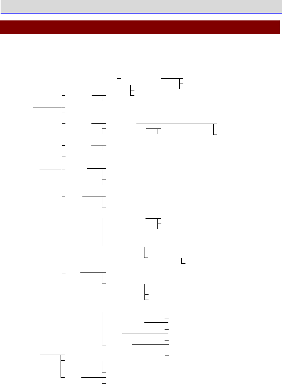
Chapter 4 System Menu 4-2 System Menu Structure
GTX-221-G User’s Manual
101
4-2 System Menu Structure
The system menu is in a hierarchical structure, classified by function.
1:System 1:Auto execute
2:Clock
3:Power Management
4:Password 1:Set
2:Clear
1:Method
2:EAP modification
1:Manual setting
2:Server setting
3:Network 1:TCP/IP
2:DHCP
3:FTP
4:DNS
5:SNMP
1:IP address
2:NetMask
3:Gateway
4:MTU
1:Startup type
2:Item not to Update
3:Server port
1:Server address
2:Name
3:Password
4:Advanced
1:Primary
2:Secondary
3:Advanced
1:Community name
2:Manager IP address
1:Community name
2:Manager IP address
1:Server port
2:Mode
3:Folder 1:Current
2:Specified
1:Select from list
2:wait(PC)
3:wait(HT)
1:Select from list
2:wait(HT)
1:Community name
2:Manager IP address
1:WLAN
2:Bluetooth
3:IrDA
1:Server port
2:Timeout time
3:Trial count
4:Cache time
1:Community(R/Only)
2:Community(R/W)
3:Trap
3:Advanced 1:Authentic trap
2:Agent port
3:Trap port
4:Trap retry
1:Set method
2:Addess
3:Name
2:WLAN 1:SSID
2:Roaming level
3:Doze mode
4:Security
5:Advanced
6:MAC address
1:Encryption
2:Authentication
3:Attention
1:Rate control
2:RTS_Threshold
1:Method
2:WEP
3:PSK(TKIP/CCMP)
1:Resume
2:Auto wake up
3:Auto power off
1:WLAN
2:Bluetooth
3:IrDA
4:Receive
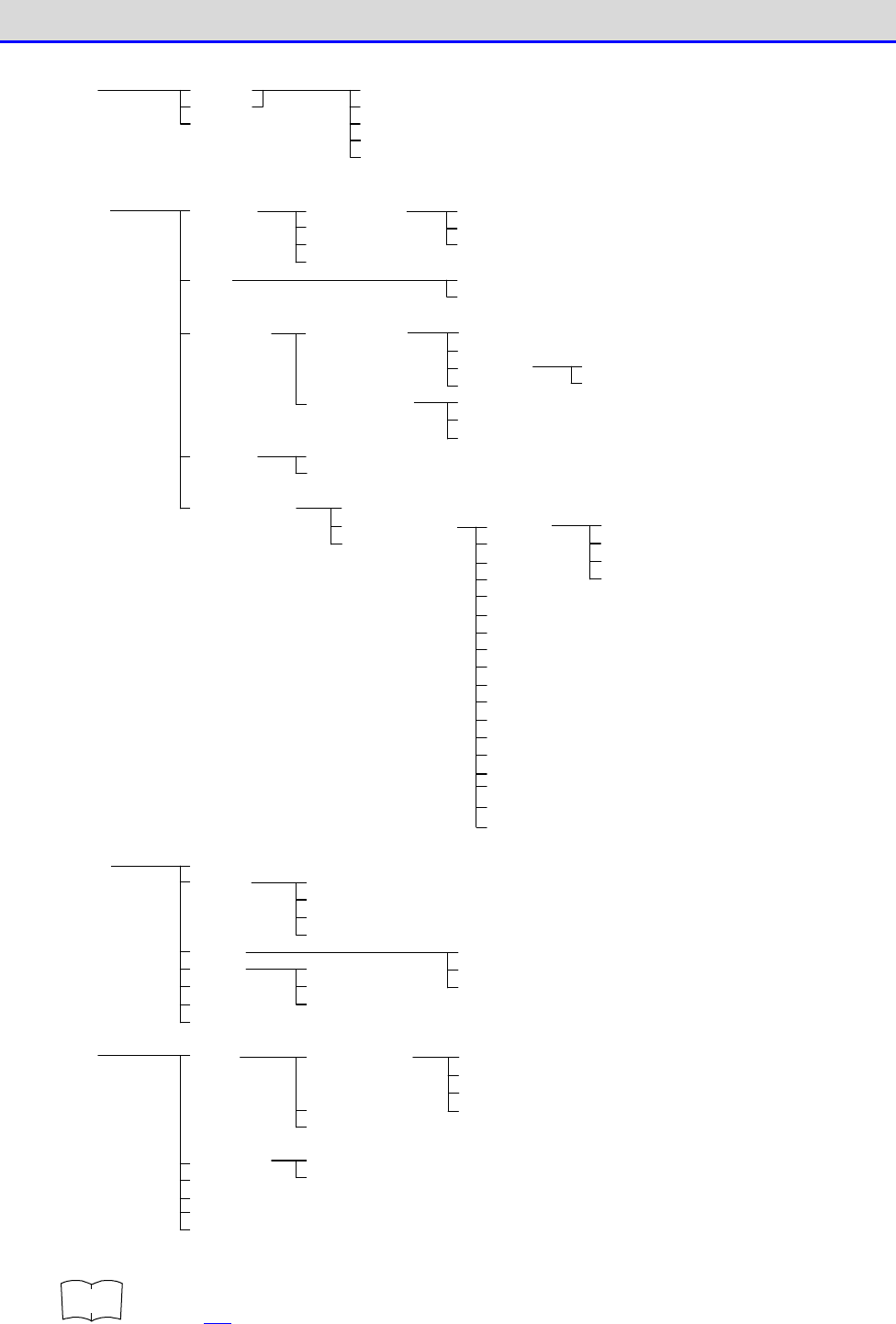
Chapter 4 System Menu 4-2 System Menu Structure
GTX-221-G User’s Manual
102
5:File
6:ID
7:Device 1:Barcode
2:Key
3:Bluetooth
4:Display
5:Tone/Vibrator
1:Trigger mode
2:Version
3:Picklist mode
4:Inverse(1D)
1:Trigger operation
2:Power saving
3:Irradiation time
1:Local device
2:Remote device
1:Device name
2:BD Address
3:Security
4:Version
1:Device list
2:Search for devices
3:Search option
1:Volume
2:Indicator func
3:Click Sound
1:Cancel1
2:Cancel2
3:Cancel3
4:Enter1
5:Enter2
6:Enter3
7:Click1
8:Click2
9:Click3
10:Caution1
11:Caution2
12:Caution3
13:Error1
14:Error2
15:Error3
16:User1
17:User2
18:User3
8:Manage 1:System info
2:Format
3:Clone
4:Drive
5:Mothball
6:Wizard
7:OS Version Up
1:FDrive
2:SDrive
3:RDrive(microSD)
1:Master
2:Slave
1:Bluetooth
2:IrDA
3:microSD
1:RegistryInitialize
2:FDrive
3:SDrive
4:RDrive(microSD)
1:Application
2:Data
3:Audio
4:Graphic
5:All type
1:FDrive
2:SDrive
3:RDrive(microSD)
9:Test 1:WLAN
2:Bluetooth
3:IrDA
4:Barcode test
5:Display test
6:Key test
1:Configuration
2:WLAN/ping
3:AP Search
1:Host address
2:Packet size
3:Timeout time
4:Trial count
1:Key repeat delay
2:Key repeat rate
1:Pairing Enable
2:PIN code
1:Luminosity
2:Light Sensor
1:Buzzer
2:Audio
3:Vibrator
4:LED
(Each item has these
four options.)
r
rr
re
ee
ef
ff
f
For the factory setting of the system menu, see "Appendix-1 Factory Default List"
(P.232).
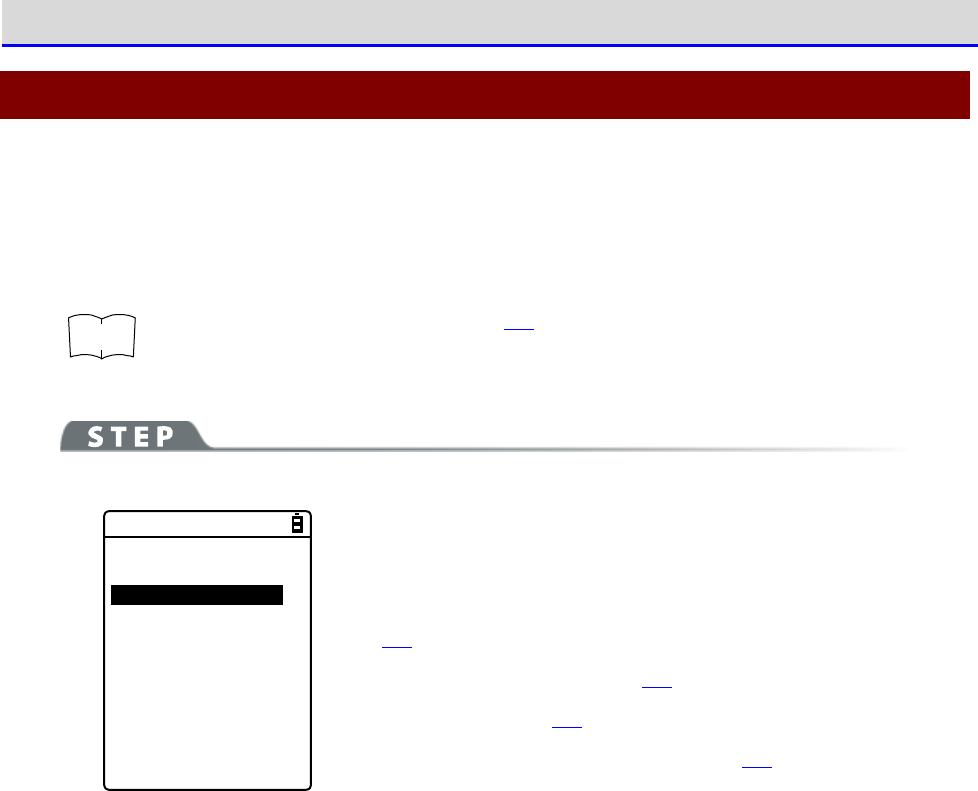
Chapter 4 System Menu 4-3 System: Settings to Simplify Your Operations
GTX-221-G User’s Manual
103
4-3 System: Settings to Simplify Your Operations
You can set various functions that make your operations of the Handy Terminal more comfortable.
You can automatically register the settings for the respective systems (except the password
setting) by using the DHCP function.
r
rr
re
ee
ef
ff
f
"4-5-2 DHCP: DHCP Settings" (P.133)
[System Menu]→[1:System]
< System setting >
1:Auto execute
2:Clock
3:Power management
4:Password
Select the item to be set.
・Auto execute: Automatic execution of the application software
(P.103)
・Clock: Clock Verification (P.104)
・Power Management (P.107)
・Password: Setting/Clearing Password (P.107)
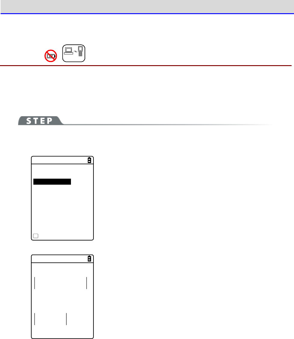
Chapter 4 System Menu 4-3 System: Settings to Simplify Your Operations
GTX-221-G User’s Manual
104
4-3-1 Auto Execute: Automatic Execution of the Application
Software
DHCP
You need to register the application software that you want launched automatically upon power
ON.
The system menu is launched by the factory settings.
[System Menu]→[1:System]→[1:Auto execute]
Select the application software you want launched automatically upon power ON.
< Auto execute >
System menu
SAMPLE1.OUT
SAMPLE2.OUT
Property
F1
After the list of currently installed programs is displayed, select
your desired application software.
Press the【ENT】key to return to the <System setting> screen.This
completes registration of the automatic execution file.
When the power is turned on the next time, the registered application
software will be launched.
< File Property >
Name
SAMPLE1.OUT
Type[Application]
Library[1.00]
Size[00000000]Bytes
Modified
2012/01/01
00:00:00
Press the【F1】key to display the information related to the selected
application software.
Press the【C】key to return to the <Auto execute> screen.
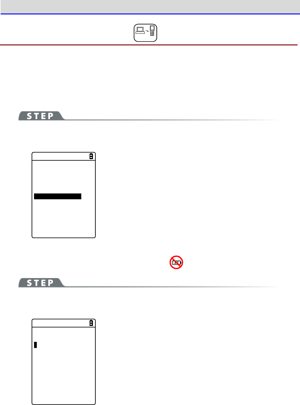
Chapter 4 System Menu 4-3 System: Settings to Simplify Your Operations
GTX-221-G User’s Manual
105
4-3-2 Clock: Time Settings
DHCP
You can verify the current time and perform time settings.
In additional to making the settings manually, you can also receive the PC time data using WLAN
communication.
■Current Time
[System Menu]→[1:System]→[2:Clock]
Select whether to set the time manually or via the server.
< Time >
2012/01/01(Sun)
00/00/00
1:Manual setting
2:Server setting
The current time is displayed.
Select the item to be set.
・Manual setting: Sets the time manually
·
・Server setting: Receives the time automatically from the server
■Manual setting: Sets the Time Manually
[System Menu]→[1:System]→[2:Clock]→[1:Manual setting]
Set the time.
< Manual setting >
2012/01/01 00:00:00
Use the arrow keys to move the cursor over the year, the month or
the day to be set, and then enter the time.
Press the【ENT】key to confirm the time and return to the <Current
time> screen.
Press the【C】key to cancel the setting and return to the <Current
time> screen.
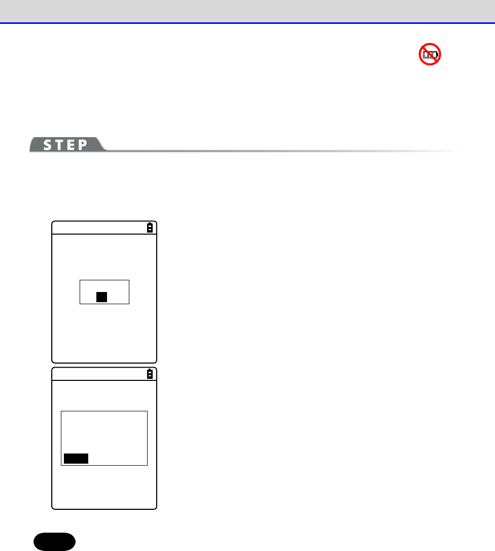
Chapter 4 System Menu 4-3 System: Settings to Simplify Your Operations
GTX-221-G User’s Manual
106
■
Server setting: Receives the time automatically from the server
Receives the time data from the DHCP server, a network administration tool (see "7-2 DHCP Server
Mode" of "Network Administration Tool User Manual").
[System Menu]→[1:System]→[2:Clock]→[2:Server setting]→
[1:WLAN]/[2:Bluetooth]/[3:IrDA]
Completed
OK
Receive the time data automatically.
Press the【ENT】key to return to the <Current time> screen.
Failed to get
the current time.
(65540)
Retry?
RETRY CANCEL
When reception fails, the screen on the left will be displayed.
・Retry: Receives the time data from the server again.
・Cancel: Cancels the setting and return to the <Current time
> screen.
If the failure persists, contact your system administrator.
Hint
To set the current time, get the time data from the server by using the DHCP
function.
When using the DHCP function to set the current time, confirm the following in
advance:
・The WLAN communication (such as SSID and security) between the Handy Terminal
and the access point has been configured correctly.
・The access point and the PC have been powered up.
・The access point and the PC have been configured and connected correctly.
・The access point is operating normally.
・The DHCP server of the network administration tool has been started.
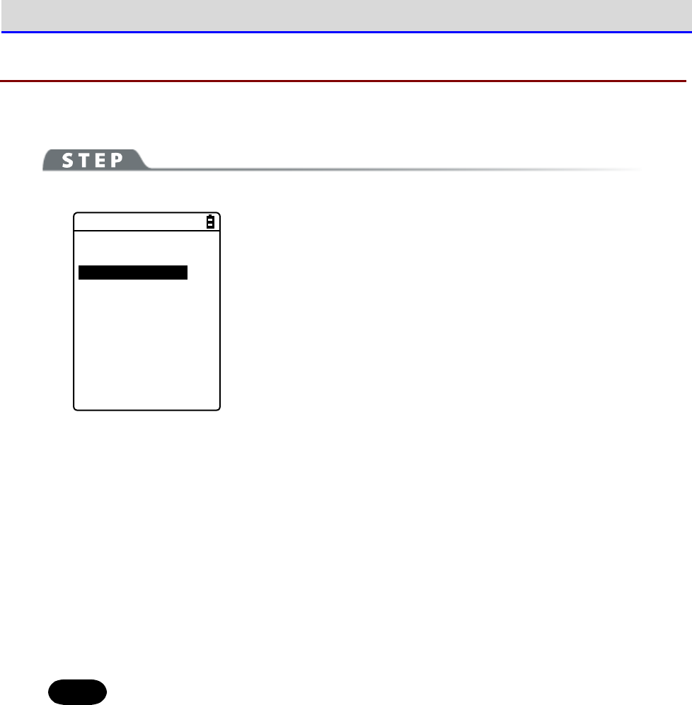
Chapter 4 System Menu 4-3 System: Settings to Simplify Your Operations
GTX-221-G User’s Manual
107
4-3-3 Power Management: Various Settings Related to Power
You can perform various settings related to Power ON/OFF, such as auto power off.
[System Menu]→[1:System]→[3:Power Management]
< Power management >
1:Resume
2:Auto wake up
3:Auto power off
Select the item to be set.
·
Resume: Retention of the state during power off
·
Auto wake up: Started at the predefined time
·
Auto power off: Automatically power off
■Resume Function: Retaining the State during Power OFF
If the resume function is enabled, the state when the power was turned off is saved, allowing
you to resume your work thereafter upon the next startup.
The operations after pressing the【PW】key to turn on the power are as follows, depending on
whether the resume function is enabled:
•
Resume function enabled: Resumes from the process executed immediately before power off.
•
Resume function disabled: Always executed from the beginning process.
Hint
To cancel the resume function and launch the system menu, press the【PW】key while
holding down the SCAN key.
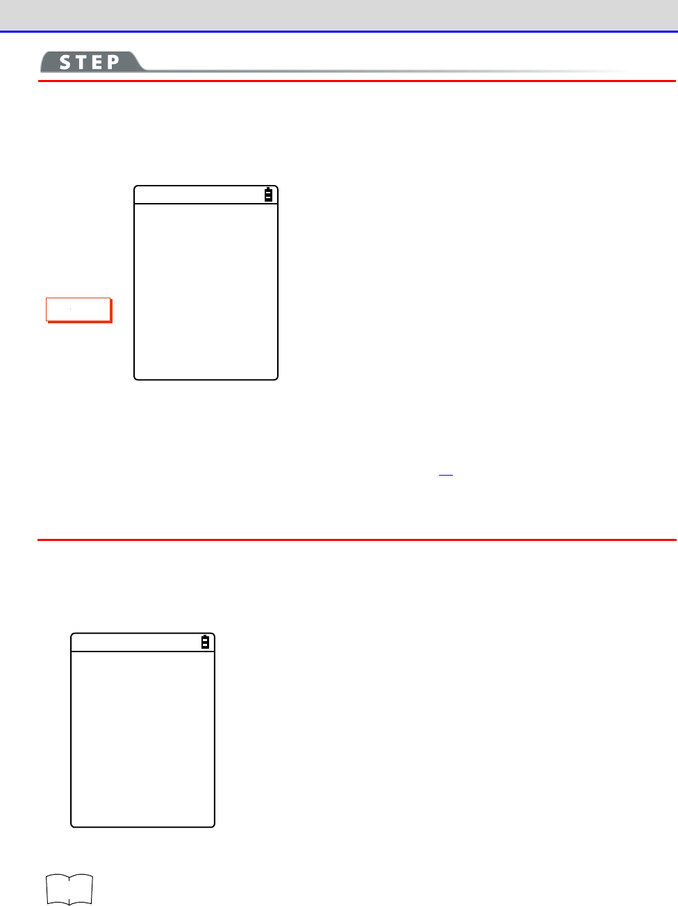
Chapter 4 System Menu 4-3 System: Settings to Simplify Your Operations
GTX-221-G User’s Manual
108
C
a
u
t
i
o
n
・If the battery pack is detached during operation, resume will fail. The process
will then be executed from the beginning, regardless of whether the resume
function is enabled or disabled. The following screen will be displayed upon
the next power on.
Backup failure.
Format S drive.
Start up this
terminal usually.
Hit ENT key.
・When the backup battery is depleted, the above screen will be displayed, and
the process will be executed from the very beginning. For charging the backup
battery, see "1-2-5 Remaining Charge Level Display and Alarm for the Battery
Pack"-"■Charging the Backup Battery" (P.49).
・The resume is disabled on the system menu even when the resume setting is enabled.
The resume is enabled only while the application software is operating.
[System Menu]→[1:System]→[3:Power Management]→[1:Resume]
Enable the resume function.
< Resume >
Enabled
Press the【ENT】key to select[Enabled].
r
rr
re
ee
ef
ff
f
You can also enable the resume function from the DHCP server, a network ad-
ministration tool (see "7-2 DHCP Server Mode" of "Network Administration Tool
User Manual").

Chapter 4 System Menu 4-3 System: Settings to Simplify Your Operations
GTX-221-G User’s Manual
109
■Auto wakeup: Started at the Predefined Time
The auto wake up function can automatically start the Handy Terminal according to a predefined
schedule.
C
a
u
t
i
o
n
The auto wake up function can be enabled only if the power is turned off using
the【PW】Key. The Handy Terminal cannot be started by Auto wake up immediately
after battery replacement or after forcible termination due to low battery.
●Schedule Confirmation
[System Menu]→[1:System]→[3:Power Management]→[2:Auto wake up]
The currently set start schedule is displayed.
Select the item to be set.
< Present schedule >
at 07:30
on Monday
every week.
1:Set
2:Clear
Select from the following items:
・Set: Sets the schedule
・Clear: Clears the schedule
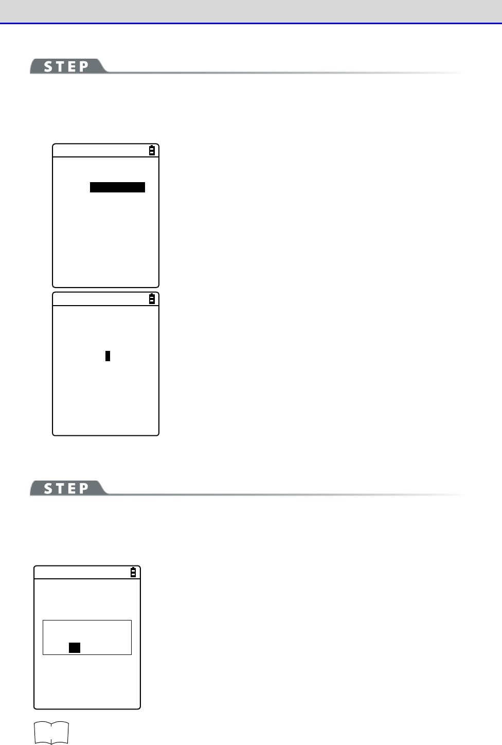
Chapter 4 System Menu 4-3 System: Settings to Simplify Your Operations
GTX-221-G User’s Manual
110
●Set: Sets the Schedule
[System Menu]→[1:System]→[3:Power Management]→[2:Auto wake up]
→[1:Set]
Set the auto wakeup schedule.
< Schedule setting >
Cycle [every day ]
every week
every month
Select the occurrence interval of the schedule.
Select Daily (time specification), Weekly (weekday and time
specification), Monthly (date and time specification). Date is set
using "01"
–
"31", and time is set using the 24-hour format. The menu
returns to schedule confirmation upon completion of the setting.
< Schedule setting >
Cycle [every month]
Date [01]
Time [01:00]
Enter the hours and minutes (00:00
–
23:59) in the 24-hour format.
This completes the settings.
Press the【ENT】Key to return to the<Current schedule> screen and
complete the setting.
●Clear: Clear the Schedule
[System Menu]→[1:System]→[3:Power Management]→[2:Auto wake up]
→[2:Clear]
Clear the auto wakeup schedule that has been set.
< Schedule clear >
Would you like to
clear schedule?
YES NO
Select[Yes]in the confirmation dialog.
The set schedule is deleted.
Select[No]to cancel the clearing.
r
rr
re
ee
ef
ff
f
You can also enable the auto wakeup function from the DHCP server, a network
administration tool (see "7-2 DHCP Server Mode" of "Network Administration Tool
User Manual").
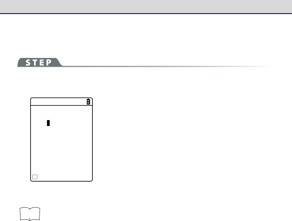
Chapter 4 System Menu 4-3 System: Settings to Simplify Your Operations
GTX-221-G User’s Manual
111
■Auto Power OFF: Automatic Power OFF
The auto power off function performs power off automatically after a time period of no
operation.
[System Menu]→[1:System]→[3:Power Management]→[3:Auto power off]
Set the time duration after which power off is to be performed automatically.
< Auto power off >
[0600] Sec
Guidance
F1
The allowed time range is 0060
–
3600 seconds.
In addition, power off can be disabled by setting it to 0000 second.
Press the【ENT】key to complete the setting.
Press the【F1】key to display the guidelines related to the setting
values.
r
rr
re
ee
ef
ff
f
You can also enable the auto power off function from the DHCP server, a network
administration tool (see "7-2 DHCP Server Mode" of "Network Administration Tool
User Manual").
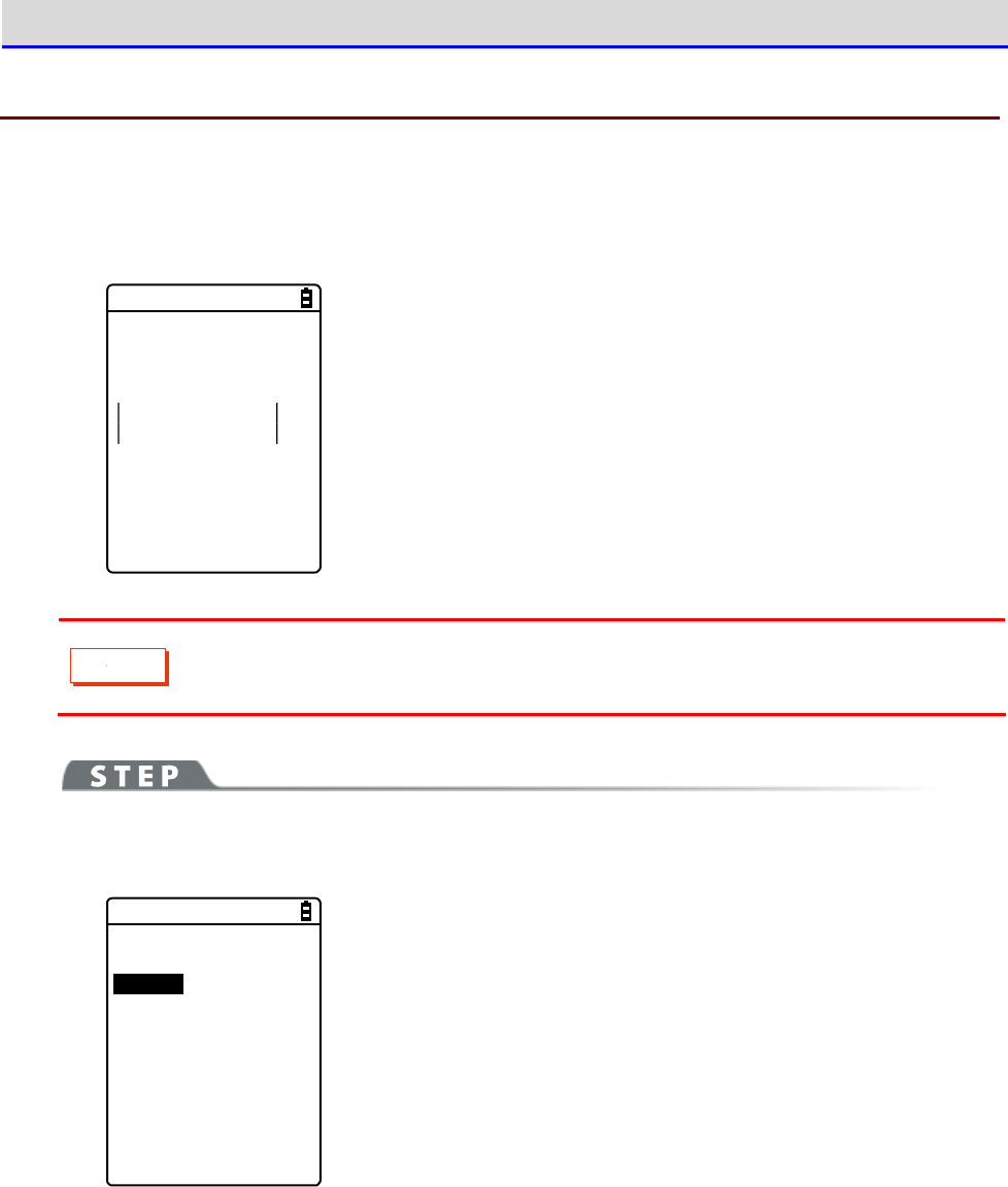
Chapter 4 System Menu 4-3 System: Settings to Simplify Your Operations
GTX-221-G User’s Manual
112
4-3-4 Password: Setting / Clearing Password
You can set a password to prevent the system menu from being inadvertently started. If a password
has been set, no person other than the administrator can confirm and/or modify the settings
without entering the password.
Password?
***
If a password has been set, password check will be performed during
system menu launch. The system menu will not be launched unless the
correct password is entered.
C
a
u
t
i
o
n
Write down your password and keep it somewhere safe in order not to forget it.
Please contact your dealer if you are unable to recall the password.
[System Menu]→[1:System]→[4:Password]
You can set or clear the password.
< Password >
1:Set
2:Clear
Select from the following items:
・Set
・Clear
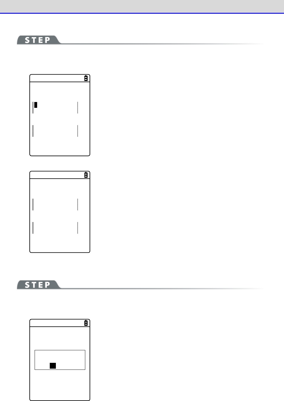
Chapter 4 System Menu 4-3 System: Settings to Simplify Your Operations
GTX-221-G User’s Manual
113
■Set: Setting the Password
[System Menu]→[1:System]→[4:Password]→[1:Set]
①
Enter a new password.
< Password setting >
New password
New password again
The password is case sensitive and consists of 4
–
30 alphanumeric
characters.
Enter a new password, and then press the【ENT】key.
②
Enter the password once again for confirmation.
< Password setting >
New password
abcd
New password again
Press the【ENT】key after entering the password.
■Clear: Clearing the Password
[System Menu]→[1:System]→[4:Password]→[2:Clear]
Clear the password.
< Password clear >
Would you like to
clear a password?
YES NO
Select[Yes]to clear the password; the set password will be erased.
Select[No]to cancel the clearing.
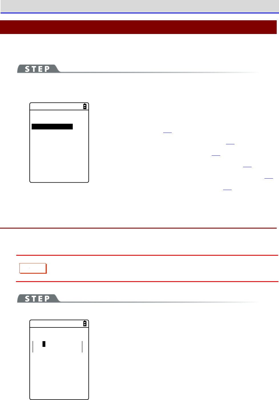
Chapter 4 System Menu 4-4 WLAN: WLAN Communication Settings
GTX-221-G User’s Manual
114
4-4
WLAN: WLAN Communication Settings
You can perform settings related to WLAN.
[System Menu]→[2:WLAN]
You can select the setting item for WLAN communication.
< WLAN >
1:SSID
2:Roaming level
3:Doze mode
4:Security
5:Advanced
6:MAC address
Select the item to be set.
・SSID: Setting SSID (P.114)
・Roaming level: Setting the Roaming Level (P.115)
・Doze mode: Setting the Timeout Time (P.115)
・Security: WLAN Communication Security Settings (P.116)
・Advanced: Advanced Settings Related to WLAN Communication (P.127)
・MAC address: Displaying the MAC Address (P.129)
4-4-1 SSID: Setting SSID
You can set SSID for identifying the access point of WLAN communication.
C
a
u
t
i
o
n
Although SSID can be set automatically by using the DHCP function, security issues
may occur. Avoid configuration by DHCP.
[System Menu]→[2:WLAN]→[1:SSID]
< SSID >
101
Enter SSID.
SSID is specified with up to 32 alphanumeric characters.It is case
sensitive.
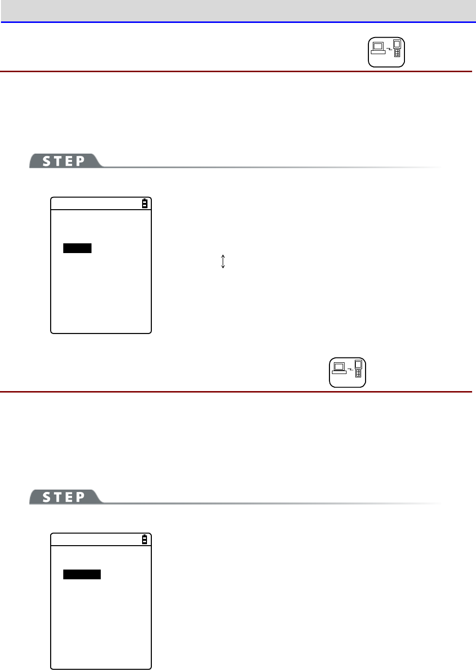
Chapter 4 System Menu 4-4 WLAN: WLAN Communication Settings
GTX-221-G User’s Manual
115
4-4-2 Roaming level: Setting the Roaming Level DHCP
The roaming function automatically switches to an access point with a stronger signal when the
Handy Terminal is moved around. The value for deciding the switching is called roaming level.
Roaming is performed only among access points having the same SSID.
[System Menu]→[2:WLAN]→[2:Roaming level]
< Roaming level >
Slow
Normal
Fast
Select the speed for deciding the switch.
Slow The switch is slow
Normal
Fast The switch is fast
4-4-3 Doze mode: Setting the Timeout Time DHCP
This time is the duration after which WLAN is switched to the doze mode upon completion of
transmission. The shorter this time, the lower the consumption of the battery pack. However,
the WLAN response will be degraded accordingly.
It can be configured automatically if the DHCP function is enabled.
[System Menu]→[2:WLAN]→[3:Doze mode]
< Doze mode >
Quick
1 second
None
Select the time duration after which timeout occurs.
Chapter 4 System Menu 4-4 WLAN: WLAN Communication Settings
GTX-221-G User’s Manual
116
4-4-4
Security: WLAN Communication Security Settings
DHCP
You can perform settings related to WLAN communication security.
[System Menu]→[2:WLAN]→[4:Security]
< Security >
1:Encryption
2:Authentication
3:Attention
Select the item to be set.
・Encryption: Sets the encryption method and the key
・Authentication: Selects the authentication method
・Attention: Notification when security is not configured
■Encryption
You can select the encryption method and set the key used for encryption.
[System Menu]→[2:WLAN]→[4:Security]→[1:Encryption]
< Encryption >
1:Method
2:WEP
3:PSK(TKIP/CCMP)
Select the item to be set.
・Method: Selects the encryption method
・WEP: Sets the WEP key
・PSK(TKIP/CCMP): Sets the encryption key
Chapter 4 System Menu 4-4 WLAN: WLAN Communication Settings
GTX-221-G User’s Manual
117
●Method
You can select the encryption method.
[System Menu]→[2:WLAN]→[4:Security]→[1:Encryption]→[1:Method]
< Method >
Disabled
WEP(40 bit)
WEP(128bit)
TKIP
CCMP
Select the encryption method.
・Disabled
・WEP(40-bit)
・WEP(128-bit)
・TKIP
・CCMP(AES)
●WEP
[System Menu]→[2:WLAN]→[4:Security]→[1:Encryption]→[2:WEP]
< WEP >
1:TxKeyID
KEY-1
KEY-2
KEY-3
KEY-4
2:Key modification
Select the item.
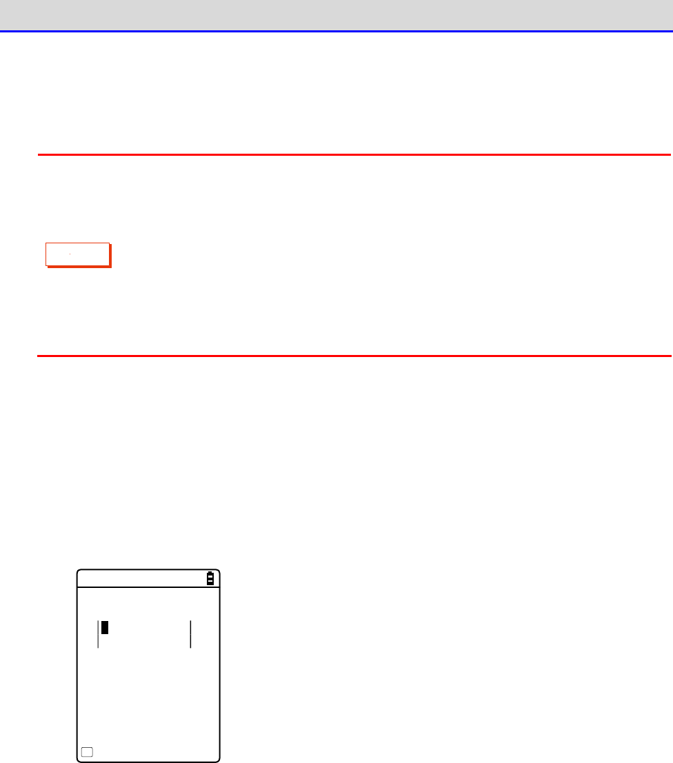
Chapter 4 System Menu 4-4 WLAN: WLAN Communication Settings
GTX-221-G User’s Manual
118
・TxKeyID
From the KEY1
–
KEY4 set at the next[Key modification], select the ID used for communi-
cation.This item is enabled while the WEP setting is other than "Disabled".
C
a
u
t
i
o
n
Communication cannot be performed unless the WEP key value of TxKey_ID set here
matches with the WEP key value of the access point and the WEP key value of
TransmitKEY set at the access point matches with the WEP key value on the Handy
Terminal side.
For example, if TxKey_ID of the Handy Terminal is "2", the WEP key2 value of the
Handy Terminal and the WEP key2 value of the access point must be consistent. Also,
if TransmitKEY of the access point is "3", the WEP key3 value of the access point
and the WEP key3 value of the Handy Terminal must match each other.
・Key modification
You can set the value of the respective WEP keys (1, 2, 3, 4).
The value can contain HEX characters ("0"
–
"9", "A"
–
"F") and ASCII characters.Press the【F1】
Key to switch the input. You can also make the setting through barcode reading by using the
trigger keys.
HEX Characters (Default)
<Key-1 modification>
0000000000000
0000000000000
ASCII
F1
The length is fixed at 10 characters when 40-bit is selected,
and at 26 characters when 128-bit is selected. The actual entry
is always 26 characters, and when 40-bit is selected, only the
first 10 of these 26 characters are accepted.
Press the【F1】key to move to the ASCII character entry screen.
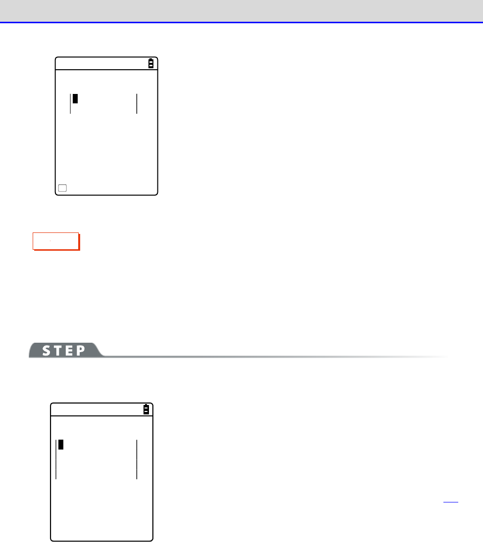
Chapter 4 System Menu 4-4 WLAN: WLAN Communication Settings
GTX-221-G User’s Manual
119
ASCII Characters
<Key-1 modification>
HEX
F1
The length is fixed at 5 characters when 40-bit is selected,
and at 13 characters when 128-bit is selected. The actual entry
is always 13 characters, and when 40-bit is selected, only the
first 5 of the 13 characters are accepted. In addition, blank
is recognized as space (0x20).
C
a
u
t
i
o
n
The settings for the respective WEP keys can be overwritten but not edited.
From the security perspective, it is always displayed as "00000..." when moving
to the KEY modification screen.
●PSK(TKIP/CCMP)
[System Menu]→[2:WLAN]→[4:Security]→[1:Encryption]
→[3:PSK(TKIP/CCMP)]
< PSK(TKIP/CCMP) >
When PSK (TKIP/CCMP) is selected in the encryption method, enter
the encryption key (key). Perform the same setting as for the access
point.
You can enter 8
–
63 characters when setting using ASCII charac-
ters.You can enter 64 characters when setting using HEX numbers.
To use PSK (TKIP/CCMP), set the authentication method (P.121) to
"Open".

Chapter 4 System Menu 4-4 WLAN: WLAN Communication Settings
GTX-221-G User’s Manual
120
About Security Function
The Handy Terminal is equipped with WPA and WPA2 as WLAN communication security functions.
■About WPA (WPA-PSK) and WPA2 (WPA2-PSK)
・PSK
PSK is short for Pre-Shared Key.
You need to set the same encryption key for both the access
point and the Handy Terminal before performing WLAN communication between them.
This key must
be managed such that it cannot be leaked to any third party.
In this context, the key set
in WEP is also a PSK.
・WPA-PSK and WPA2-PSK
As equipment cost and technology, such as RADIUS server and electronic certificates required
for IEEE802.1X (EAP) authentication, are required, t
he PSK method is prepared as a simple
authentication method for WPA and WPA2.
This also performs simple authentication by setting the same PSK in advance both in the access
point and in the Handy Terminal, and performs communication by the set encryption m
ethod
(TKIP/CCMP(AES)).
Instead of directly using the PSK as the encryption key, this method
periodically generates a temporal key for any connection between each access point and each
terminal. Due to this process, compared with "No Encryption" or "WEP Me
thod", a delay of
several seconds occurs during WLAN communication with the access point.
■Encryption Method
The Handy Terminal has the following encryption methods:
・WEP
As the IEEE802.11b/g used during WLAN communication of the Handy Terminal is a gener
al wireless
standard, it may be easily intercepted by third parties.Using WEP (Wired Equivalent Privacy),
the encryption standard, for WLAN communication data between the access point and the
Handy
Terminal allows you to avoid the risk of being intercepted. The Handy Terminal
supports two
types of WEP keys (common keys): "40-bit (or 64-bit)" and "128-bit".
・TKIP
TKIP, part of the encryption standard for IEEE802.11iWLAN communication, is short for
"Temporal Key Integrity Protocol", the encryption protocol used for a temporal key.
This
function compensates for WEP vulnerability while using the encryption algor
ithm RC4 used in
WEP.Instead of encrypting the temporal key using RC4 without change, it realizes encryption
with a different key for each packet by performing key mixing process in two steps.
・AES
AES is an encryption method adopted by the U.S. government
, and uses a standard encryption
algorithm called Rijndael.
AES satisfies the two conditions of safety and speed.However, as
this algorithm is totally different from WEP or TKIP, new hardware process will be required.
・CCMP
CCMP (Counter mode with CBC-MAC Protocol) is a tamper detection protocol used by AES.
The
CBC-MAC (Cipher-Block Message Authentication Code) method is used to detect tampering.
This
CCMP method is required by WPA2 (IEEE802.11i).
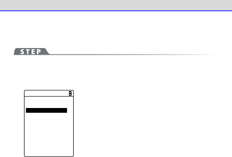
Chapter 4 System Menu 4-4 WLAN: WLAN Communication Settings
GTX-221-G User’s Manual
121
■Authentication
Select the authentication method.
[System Menu]→[2:WLAN]→[4:Security]→[2:Authentication]
Select the item to be set.
< Authentication >
1:Method
2:EAP modification
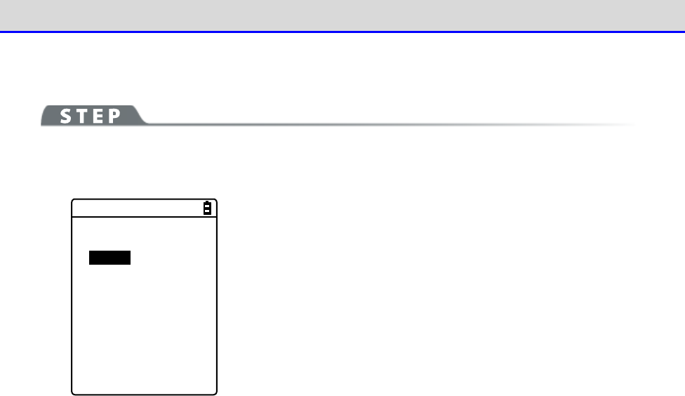
Chapter 4 System Menu 4-4 WLAN: WLAN Communication Settings
GTX-221-G User’s Manual
122
●Method
[System Menu]→[2:WLAN]→[4:Security]→[2:Authentication]-[1:Method]
< Authentication >
Open
Shared
EAP
・Open
Set "Open Authentication" method.
When the authentication request frame is received from the Handy
Terminal, the access point returns with an authentication
response frame and enables the data communication.
While WEP is enabled, if the two WEP keys do not match, com-
munication will not be performed even when authentication has
taken place.
・Shared
Set "Shared Key Authentication" method.
When authentication request is received from the Handy Terminal,
the access point sends unencrypted text (challenge text) for
identity confirmation. The Handy Terminal then encrypts the
challenge text and returns the encrypted text to the access point.
The access point decrypts the encrypted text using its WEP key.
If the access point confirms that the decrypted text matches the
original challenge text, then it authenticates the Handy
Terminal.
・EAP
Sets the "EAP" (IEEE802.1X) authentication method.When this
authentication method is used, you will also need to configure
a number of settings including certificate, private key and user
information, which will be discussed later. There are also
limitations on environment that can be used (such as certificate
authority and authentication (RADIUS) server). Therefore, if you
want to use the "EAP" authentication method, please contact your
dealer.
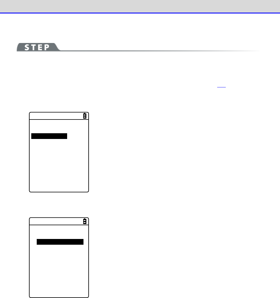
Chapter 4 System Menu 4-4 WLAN: WLAN Communication Settings
GTX-221-G User’s Manual
123
●EAP modification
[System Menu]→[2:WLAN]→[4:Security]→[2:Authentication]-[1:EAP modification]
Perform the various configurations required when using EAP (IEEE802.1X) authentication.
After these settings are configured, perform " ■ WLAN/ping test" (P.202) and verify that
communication using EAP authentication is possible.
< EAP modification >
1:EAP mode
2:Certificate
3:Private key
4:User Info
5:Advanced
Select the item to be set.
①Select[EAP mode].
< EAP mode >
EAP-TLS
EAP-PEAP-MSCHAPv2
・EAP-TLS
This authentication method requires a server certificate for
server authentication, and a client certificate for client
certification.
The required settings are as follows:
・CA root certificate
・Client certificate
・Private key
・User name
・EAP-PEAP-MSCHAPv2
This authentication method requires a server certificate for
server authentication, and a user name and a password for client
authentication.
The required settings are as follows:
・CA root certificate
・User name
・Password
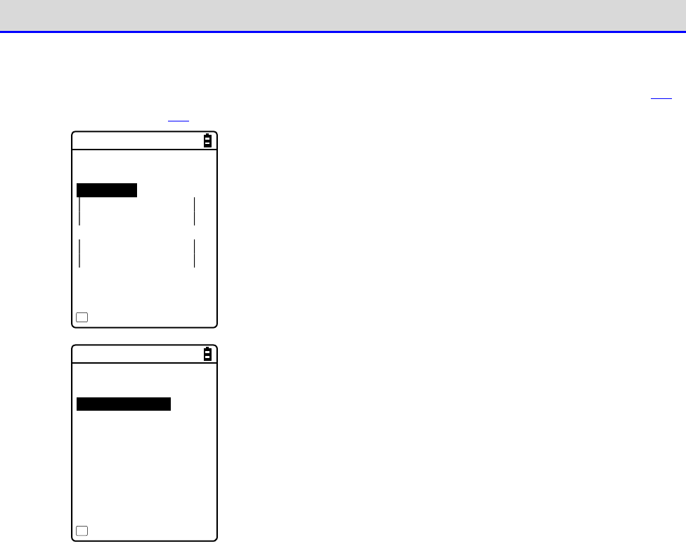
Chapter 4 System Menu 4-4 WLAN: WLAN Communication Settings
GTX-221-G User’s Manual
124
②Select[Certificate].
You need to set the certificate files.The certificate files are received via WLAN (P.146)
or Bluetooth (P.146).They can also be received via IrDA or clone.
< Certificate >
1:CA root
2:Client
Clear entry
F1
・CA root (file)
This is the CA root certificate of the publisher of the server
certificate required for server authentication. It does not
support certificate hierarchization (chain).
Press the【F1】key to clear the setting value.
・Client certificate (file)
This is a client certificate required for client authentication.
Press the【F1】key to clear the setting value.
<Reference to file>
ROOTCERT.CER
CLIENTCERT.CER
PRIVATE.KEY
Property
F1
Select from the received files.
(Pressing the【F1】Key allows you to view the file information)
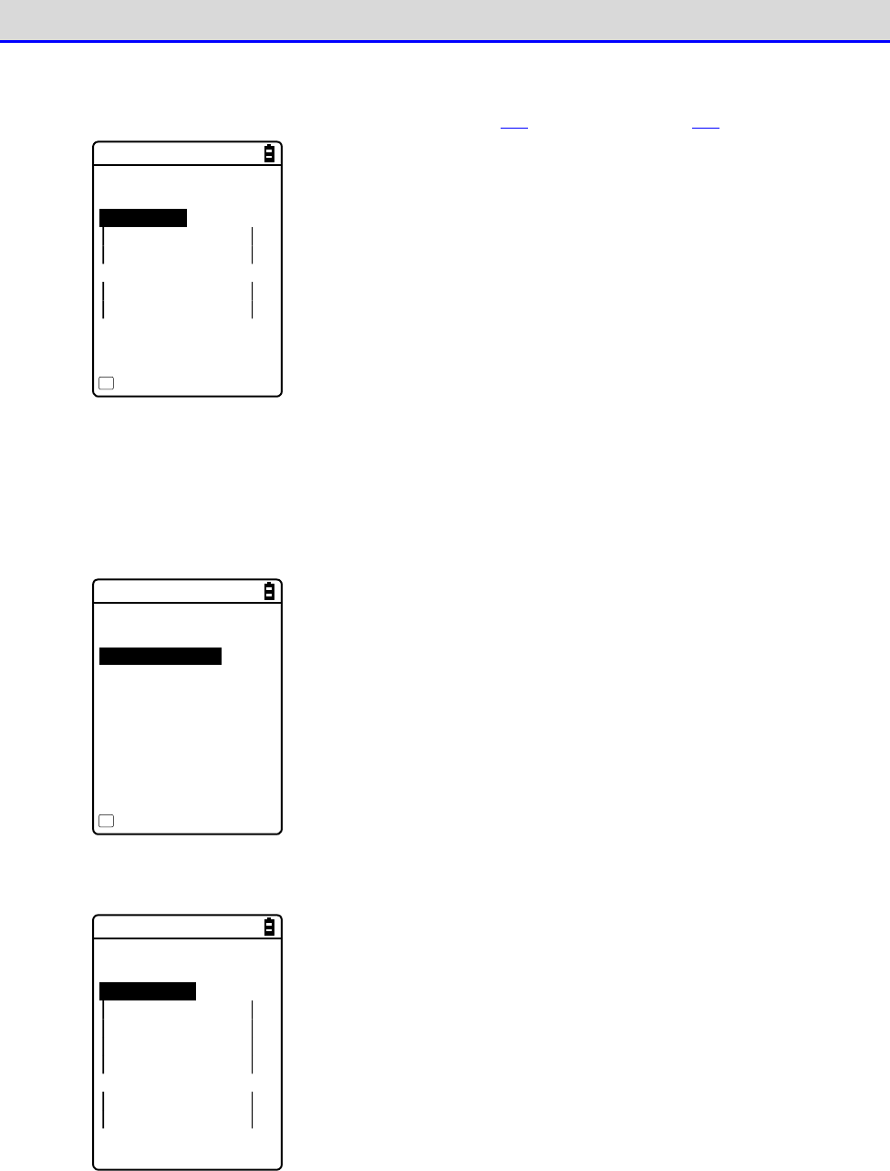
Chapter 4 System Menu 4-4 WLAN: WLAN Communication Settings
GTX-221-G User’s Manual
125
③Select[Private key].
The private key (file) is received via WLAN (P.146) or Bluetooth (P.146).
< Private key >
1:File
2:Password
****************
***************
Clear entry
F1
・File
This is the private key that is paired with the client public key
contained in the client certificate.
This private key is important for security.Manage the private key
file by encrypting it so that it will not be leaked to third
parties.
Press the【F1】key to clear the setting value.
・Password
Enter a password that is case sensitive and consists of up to 31
alphanumeric characters.
As a security measure, the password characters entered will be
displayed as asterisks (*).
Press the【F1】key to clear the setting value.
<Reference to file>
ROOTCERT.CER
CLIENTCERT.CER
PRIVATE.KEY
Property
F1
Select from the received files.
(Press the【F1】Key to view the file information)
④Select[User Info].
< User Info >
1:User Name
2:Password
****************
***************
・User Name
The user name used for authentication.
Enter a user name that is case sensitive and consists of up to
62 alphanumeric characters.
・Password
The password used for authentication.
Enter a password that is case sensitive and consists of up to 31
alphanumeric characters. As a security measure, the password
characters entered will be displayed as asterisks (*).
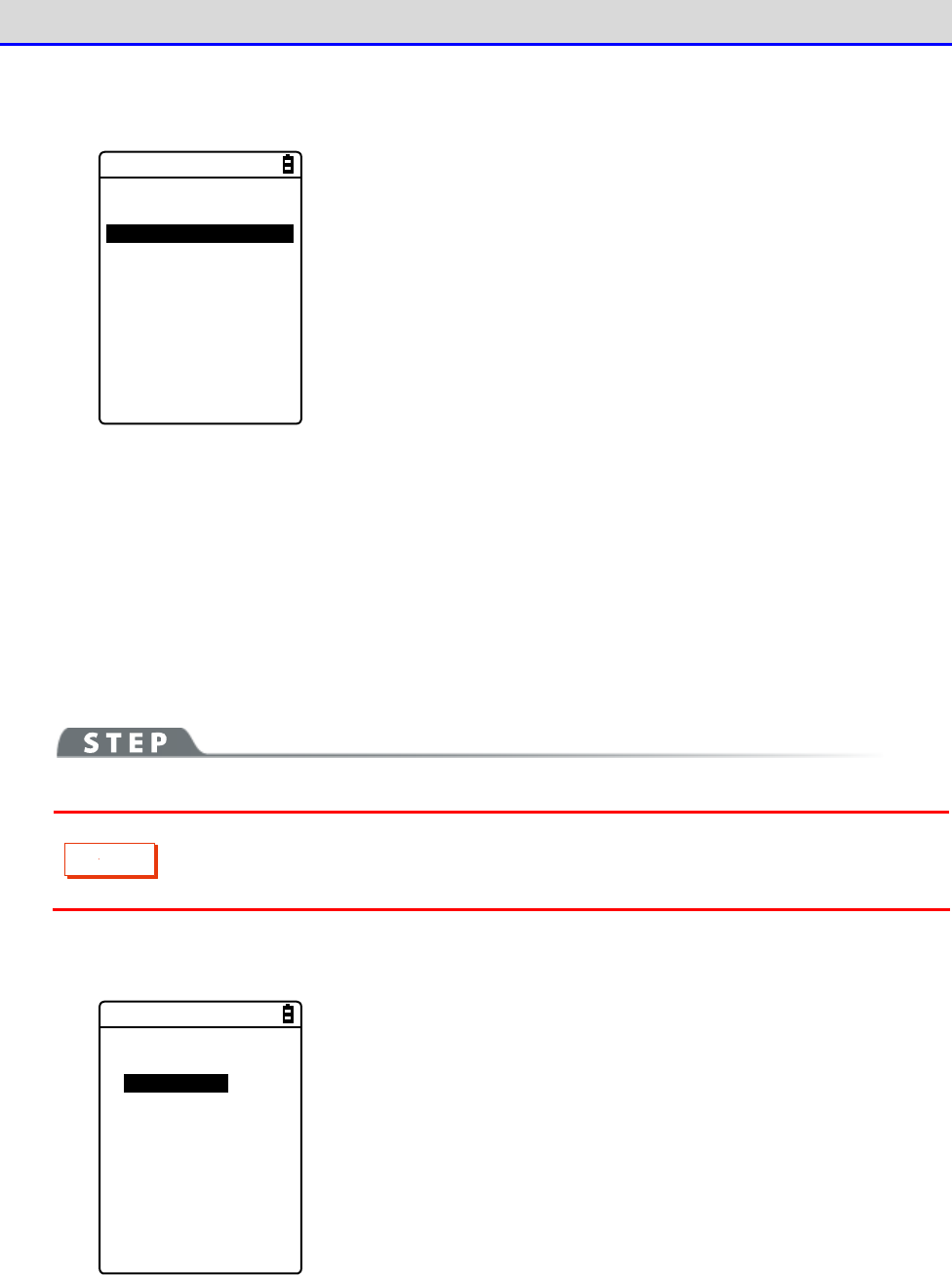
Chapter 4 System Menu 4-4 WLAN: WLAN Communication Settings
GTX-221-G User’s Manual
126
⑤Select[Advanced].
*This setting usually does not change.
< EAP Advanced >
1:AuthenticationTime
[060]sec
・Authentication timeout during startup
During WLAN startup, authentication will not be terminated till
after lapse of the number of seconds set here.
Allowed setting value: 15
–
120 seconds
■Attention
If the Handy Terminal is launched without performing the WLAN security configuration, the <WLAN
Communication Security Not Configured> prompt screen will be displayed. This display can be
shown/hidden.
If this setting is disabled, even if the WLAN communication security is not configured, the
notification screen will not be displayed during startup.
C
a
u
t
i
o
n
From the security perspective, disabling this setting is not recommended.
Be sure to configure security when performing WLAN communication.
[System Menu]→[2:WLAN]→[4:Security]→[3:Attention]
< Attention >
Display
Not Display
Select Display/Don
’
t Display.
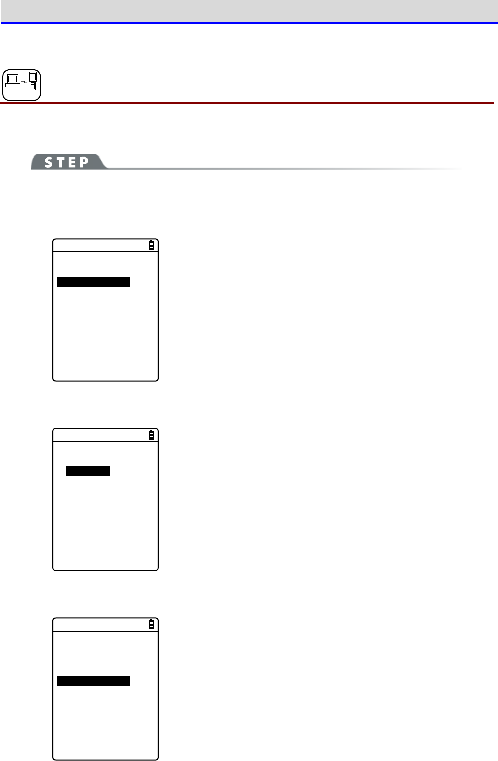
Chapter 4 System Menu 4-4 WLAN: WLAN Communication Settings
GTX-221-G User’s Manual
127
4-4-5 Advanced: Advanced Settings Related to WLAN Communication
DHCP
You can perform advanced settings related to WLAN.
[System Menu]→[2:WLAN]→[5:Advanced]
①Select [Rate control].
< Advanced >
1:Rate control
[11b Auto]
2:RTS Threshold
[2347]Bytes
②Select the transmission rate from the list.
< Rate(bps) >
01b Auto
11bg Auto
11g 9M
11g 6M
1M
2M
1 or 2M
5.5M
11M
You can select the transmission rate from the list.
For transmission rate, see the next section.
③Select[RTS_Threshold].
< Advanced >
1:Rate control
[11b Auto]
2:RTS Threshold
[2347]Bytes
You can set the RTS Threshold value.

Chapter 4 System Menu 4-4 WLAN: WLAN Communication Settings
GTX-221-G User’s Manual
128
●Transmission Rate
Setting a high-speed communication rate will narrow the area where the Handy Terminal can
perform transmission.
The rate setting on the Handy Terminal side decides whether 14ch can be used, and the rate
setting on the access point side affects the connectivity.See the following table.
Connectivity Related
to the Rate Setting on
the Access Point Side.
*2
Rate Setting
Description 14ch
*1
11b/g
Both
11b
Only
11g
Only
11b Auto
(Default)
Switches to the appropriate transmis
sion
rate according to the distance be
tween the
Handy Terminal
and the access point.Its
possible values are
given by IEEE802.11b
(11, 5.5, 2, 1 Mbps).
○ ○ ○ ×
11bg Auto
Switches to the appropriate transmis
sion
rate according to the distance be
tween the
Handy Terminal and the access point.
×
△
○
◎
11g 9M The transmission rate is fixed at 9 Mbps.
×
△
×
◎
11g 6M The transmission rate is fixed at 6 Mbps.
×
△
×
◎
1M The transmission rate is fixed at 1 Mbps.
○ ○ ○ ×
2M The transmission rate is fixed at 2 Mbps.
○ ○ ○ ×
1 or 2M The transmission rate is automatically
changed to 1 Mbps or 2 Mbps only. ○ ○ ○ ×
5.5M The transmission rate is fixed at 5.5
Mbps. ○ ○ ○ ×
11M The transmission rate is fixed at 11 Mbps.
○ ○ ○ ×
*1 14ch Enabled/Disabled?
○: Enabled.
×: Disabled.
*2 Connectivity Related to the Rate Setting on the Access Point Side.*2
◎
: Connectable.The 11g rate will take precedence, and high transmission rate is possible.
○: Connectable.Communication is performed at the 11b rate.
△
: Connectable.The throughput is reduced somewhat due to negotiation of 11b/g.
×: Non-connectable.
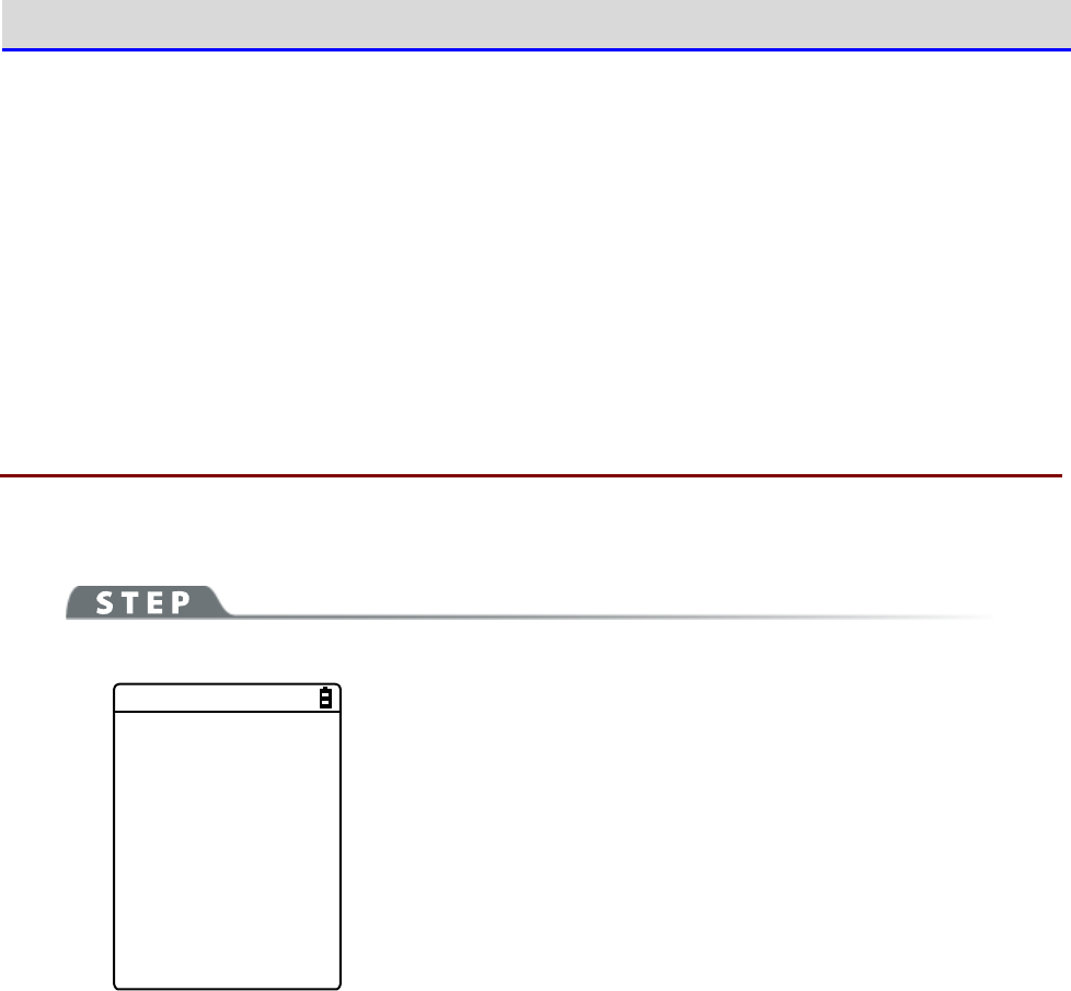
Chapter 4 System Menu 4-4 WLAN: WLAN Communication Settings
GTX-221-G User’s Manual
129
●RTS Threshold
Judges whether the RTS packet can be sent prior to data packet transmission. The RTS packet
is sent, and RTS-CTS control is performed if the data packet size is bigger than the setting
value. If one access point is connected to multiple terminals, or if the terminals are so remotely
distributed that the terminals cannot detect each other even if they can detect the access point,
the RTS-CTS control is enabled. The RTS-CTS control is enabled in the above case, but the
throughput will be reduced in other cases. Normally, retain the factory setting (2347 bytes).
·
Setting range: 0
–
2347 bytes
4-4-6 MAC address: Displaying the MAC Address
You can display the MAC address (hardware specific address). The MAC address cannot be changed.
[System Menu]→[2:WLAN]→[6:MAC address]
< MAC address >
[00:16:41:C1:B9:BD]
The MAC address of the Handy Terminal is displayed.
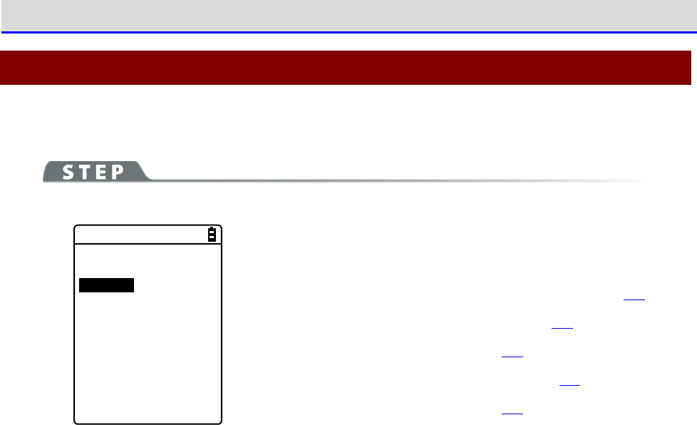
Chapter 4 System Menu 4-5 Network: Network Connection Settings
GTX-221-G User’s Manual
130
4-5 Network: Network Connection Settings
You need to perform the settings required for network connection.
[System Menu]→[3:Network]
< Network >
1:TCP/IP
2:DHCP
3:FTP
4:DNS
5:SNMP
Select the item to be set.
・TCP/IP: Settings related to TCP/IP communication (P.131)
・DHCP: Settings of DHCP client function (P.133)
・FTP: Settings for using the FTP (P.136).
・DNS: Setting for the DNS server address (P.140)
・SNMP: Various settings for SNMP (P.142)
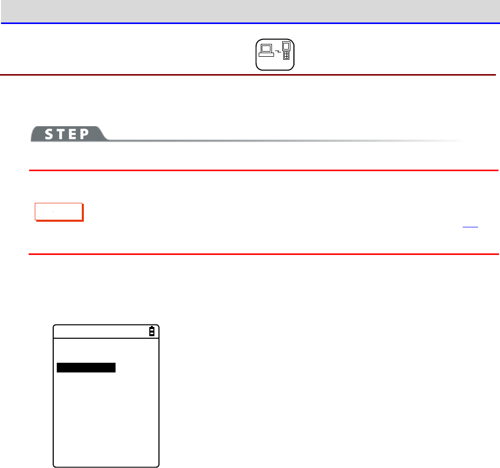
Chapter 4 System Menu 4-5 Network: Network Connection Settings
GTX-221-G User’s Manual
131
4-5-1 TCP/IP: TCP/IP Settings DHCP
You can perform settings related to TCP/IP communication, starting with IP address.
C
a
u
t
i
o
n
・While the IP address is [000.000.000.000], WLAN communication cannot be
performed.
・Unless "Application boot" is selected in DHCP settings' "■Startup type(P.134)",
all the items excluding MTU are read-only and cannot be changed.
[System Menu]→[3:Network]→[1:TCP/IP]
①
The current settings are displayed.
< TCP/IP >
1:IP Address
[000.000.000.000]
2:NetMask
[000.000.000.000]
3:Gateway
[000.000.000.000]
4:MTU
[1500]Octet
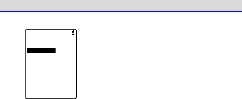
Chapter 4 System Menu 4-5 Network: Network Connection Settings
GTX-221-G User’s Manual
132
②
Configure the respective items.
< TCP/IP >
1:IP Address
[192.168.254.254]
2:NetMask
[000.000.000.000]
3:Gateway
[000.000.000.000]
4:MTU
[1500]Octet
Select the item name to make it ready for input.
・IP Address
Sets the IP address assigned by the network administrator. Sets
the unique IP addresses of all the GTX-221-Gs connected to the
same network.
・NetMask
Sets the subnet mask assigned by the network administrator. The
subnet mask needs to be set according to the IP address for
locating the affiliation of the network.
・Gateway
Sets the address of the default gateway. This setting is required
when connecting different networks via a router.
・MTU
The maximum length of an IP packet. It is usually 1500 octets
(bytes) for the Ethernet.When using across a router, this value
needs to be changed according to the communication media. For
details, contact your network administrator.
(Input example) IP address
Enter a value in the range 000
–
255 for each field separated by a
period (e.g.,192.168.254.254).
Enter the values for "NetMask" and "Gateway" using the same
procedure.
For settings related to the respective items, contact your network
administrator.
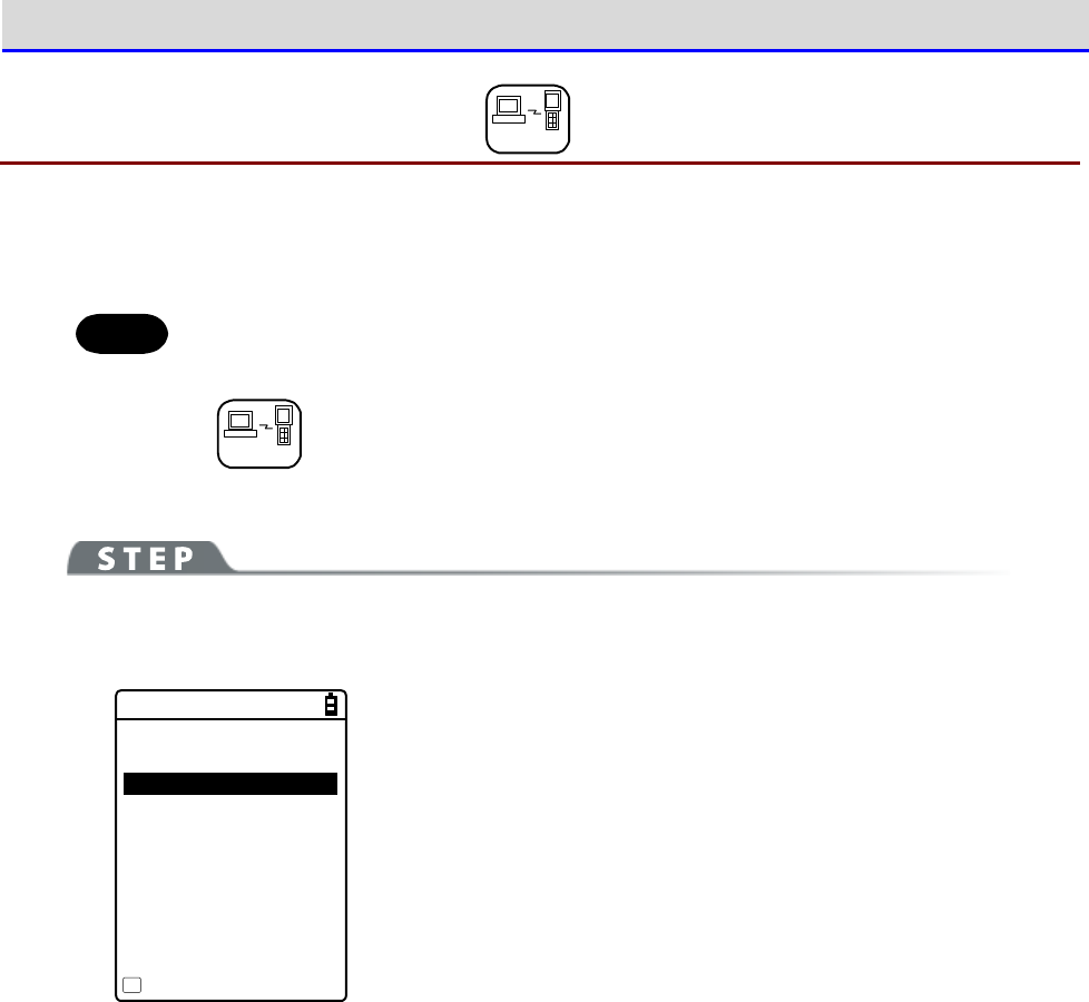
Chapter 4 System Menu 4-5 Network: Network Connection Settings
GTX-221-G User’s Manual
133
4-5-2 DHCP: DHCP Settings DHCP
You can configure the DHCP client function that can automatically configure TCP/IP and other
various settings.
Hint
This manual attaches the following mark for system menu items that can be
configured automatically from the PC by DHCP.
DHCP
[System Menu]→[3:Network]→[2:DHCP]
Select the item to be set.
< DHCP >
1:Startup type
2:Item not to Update
3:Server port
[08067]
Execute
F1
・Startup: Setting of disable/enable DHCP
・Item not to update: Setting of items for which update by DHCP is
disabled.
・Server port: Setting of the port number for the DHCP server
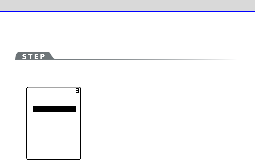
Chapter 4 System Menu 4-5 Network: Network Connection Settings
GTX-221-G User’s Manual
134
■Startup type
You can set to disable/enable DHCP upon startup.
[System Menu]→[3:Network]→[2:DHCP]→[1:Startup type]
Set the startup type.
< Startup type >
Disabled
Application boot
System menu boot
Auto wake up boot
・Disabled
DHCP will not be executed upon startup.
・Application boot
DHCP will be executed before the application software is exe-
cuted.
When the application software has been selected by[System Menu]
→
[1:System]
→
[1:Auto execute], the DHCP function will be
executed after the application software has been executed, after
startup of the Handy Terminal.
In addition, when the application software is started by[5:File]
on the system menu, DHCP will not be executed.
・System menu boot
DHCP will be executed when the system menu is launched.
・Auto wake up boot
DHCP will be executed when auto wakeup is started.
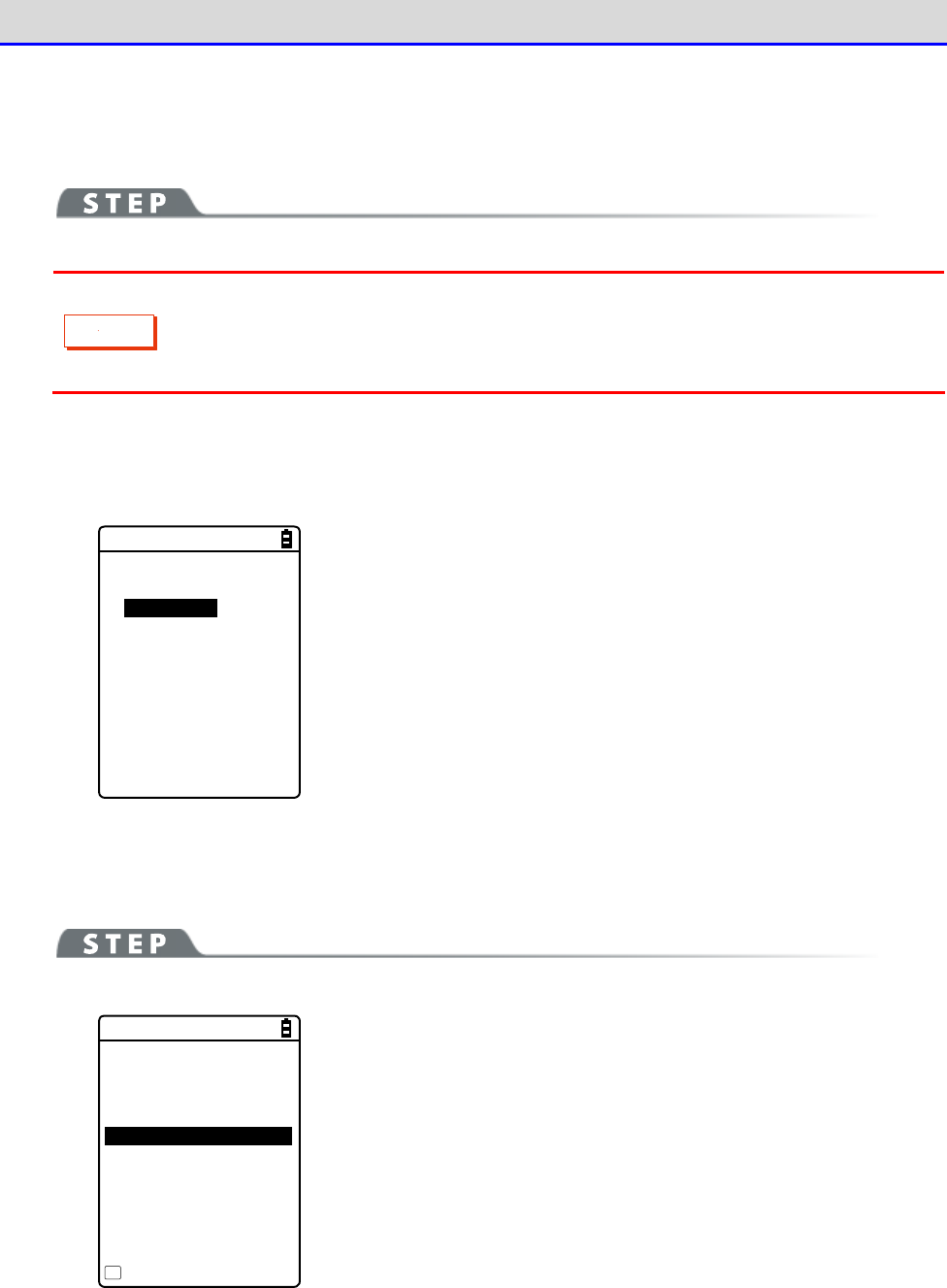
Chapter 4 System Menu 4-5 Network: Network Connection Settings
GTX-221-G User’s Manual
135
■Item not to update
You can perform settings during execution of the DHCP function so that the specified ter-
minal-specific information will not be changed.
C
a
u
t
i
o
n
If IP address is selected (IP address is disabled for update), the IP address set
for the Handy Terminal will not be changed.Use this setting after verifying that
there are no hosts with the same address in the network.
[System Menu]→[3:Network]→[2:DHCP]→[2:Item not to Update]
You can select the items whose update you want to disable.
<Item not to Update>
IP Address
NetMask
Gateway
ID
Checkmark the items whose update you want to disable.
・IP Address
・NetMask
・Gateway
・Terminal ID
■Server port
You will need to set the DHCP server port number (factory setting: 08067).
[System Menu]→[3:Network]→[2:DHCP]→[3:Server port]
< DHCP >
1:Startup type
2:Item not to Update
3:Server port
[08067]
Execute
F1
Enter the port number of the DHCP server.
This value will be changed when only configuring the IP address
using the existing DHCP server without automatically configuring
the settings specific to the Handy Terminal.
The DHCP server port number is 08067 by default. This is to avoid
conflict with other DHCP servers that are being operated in the same
network (well-known port number is 67).
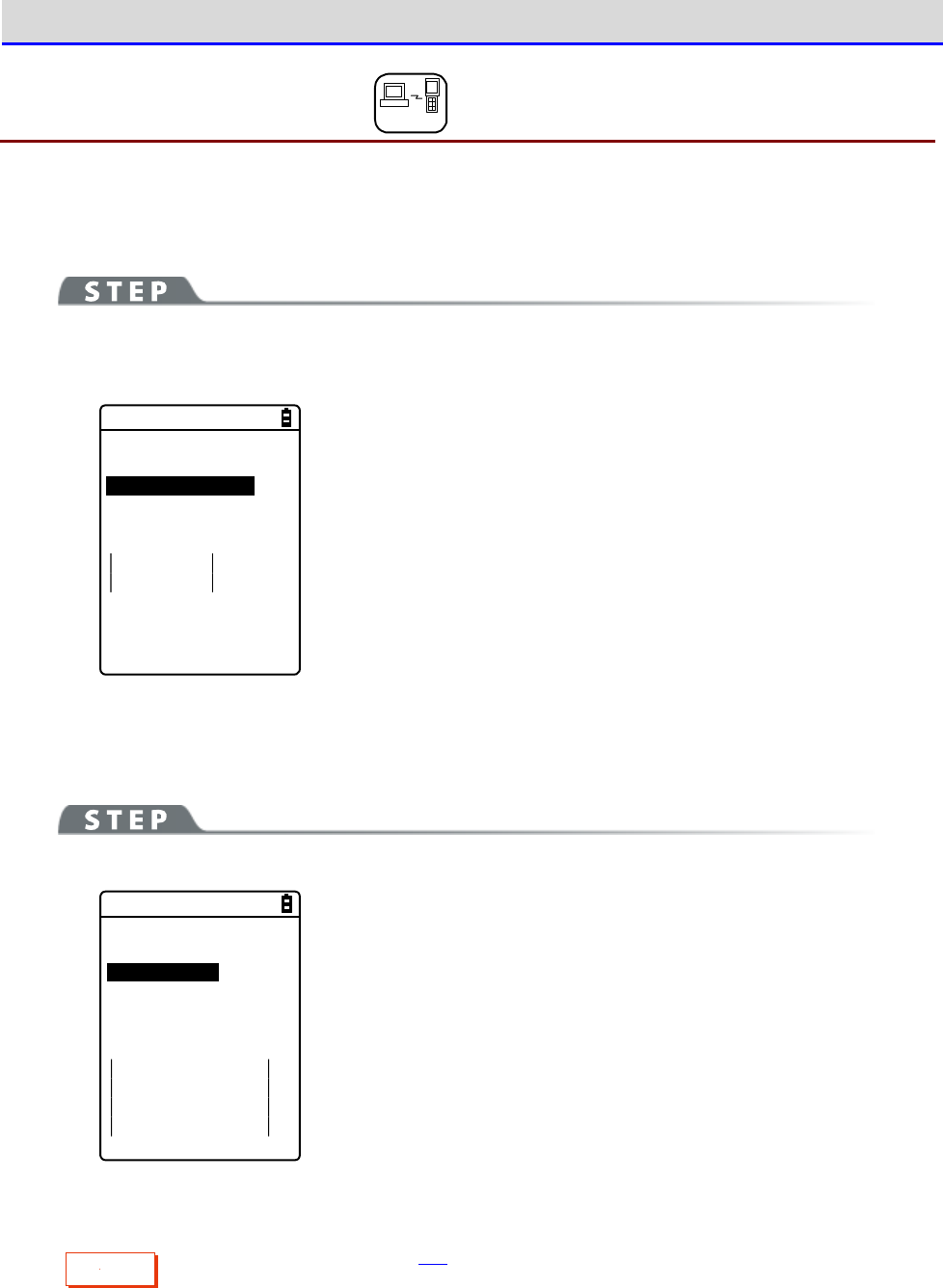
Chapter 4 System Menu 4-5 Network: Network Connection Settings
GTX-221-G User’s Manual
136
4-5-3 FTP: FTP Settings DHCP
You need to perform FTP settings when you use the FTP client function.
They can also be configured automatically if the DHCP function is enabled.
[System Menu]→[3:Network]→[3:FTP]
Select the item to be set.
< FTP >
1:Server Address
2:User name
[]
3:Password
4:Advanced
・Server address: Sets the host name of the FTP server
・User name: Sets the login user name for the FTP server
・Password: Sets the login password for the FTP server
・Advanced: Performs advanced FTP settings
■Server address
You can set the host name of the FTP server.
[System Menu]→[3:Network]→[3:FTP]→[1:Server address]
< Server address >
1:Set method
Address
Name
2:Address
[000.000.000.000]
3:Name
IP address or host name specified by "1: Set method" is set as the
FTP server.
・When IP address is selected
Enter the IP address of the FTP server under "2:Address".
・When host name is selected
Enter the host name of the FTP server under "3:Name".
Spaces cannot be included in the host name.
C
a
u
t
i
o
n
Perform DNS settings (P.140) if you want to use "Host name".
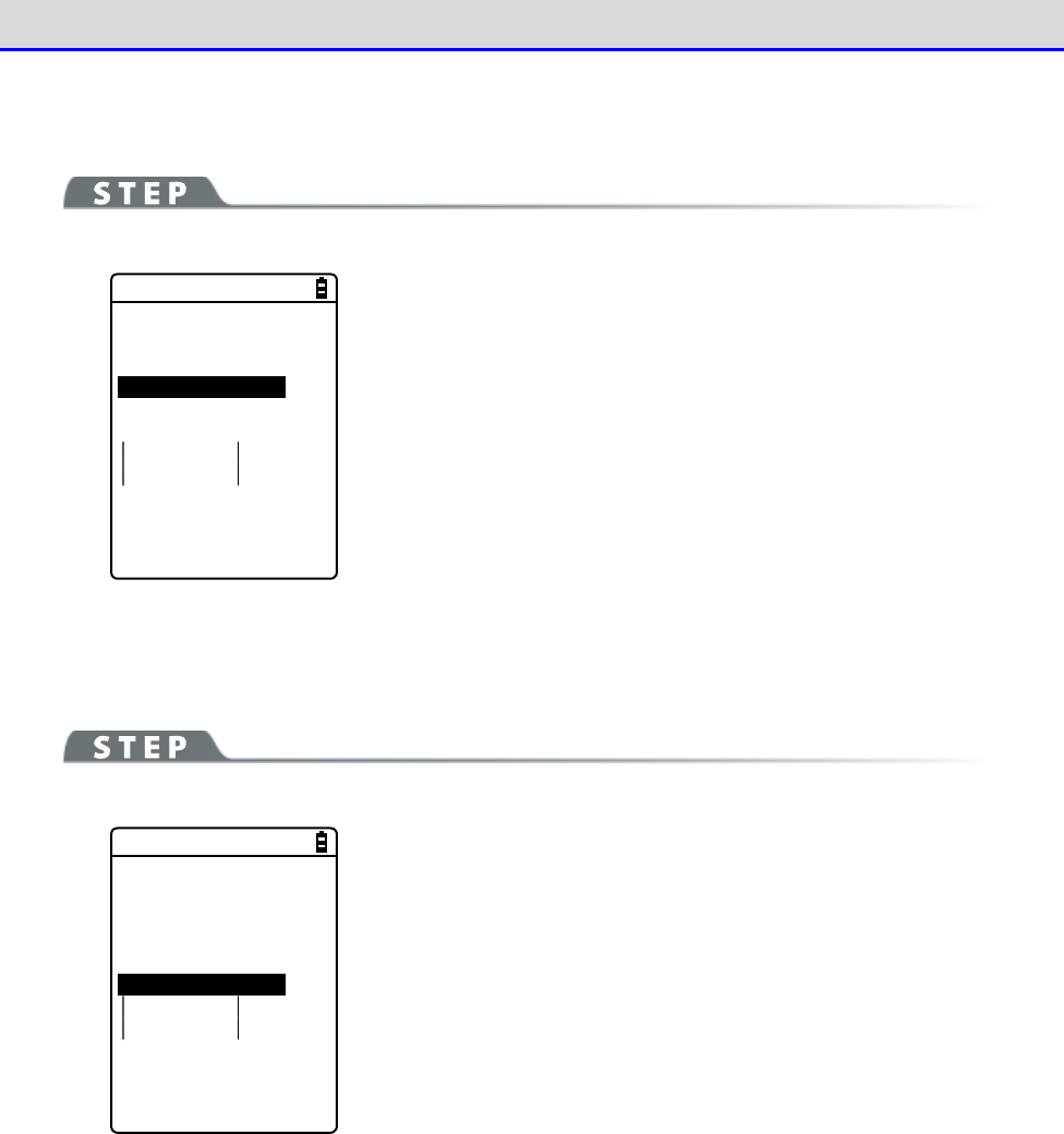
Chapter 4 System Menu 4-5 Network: Network Connection Settings
GTX-221-G User’s Manual
137
■User name
You can set the login user name for the FTP server
[System Menu]→[3:Network]→[3:FTP]→[2:Name]
< FTP >
1:Server Address
2:User name
[ ]
3:Password
4:Advanced
Enter a user name that is case sensitive and consists of up to 18
alphanumeric characters.
■Password
You can set the login password for the FTP server
[System Menu]→[3:Network]→[3:FTP]→[3:Password]
< FTP >
1:Server Address
2:User name
[ ]
3:Password
4:Advanced
Enter a password that is case sensitive and consists of up to 20
alphanumeric characters.
Spaces cannot be included in the password.
As a security measure, the password entered will be displayed after
being converted to an asterisk (*).
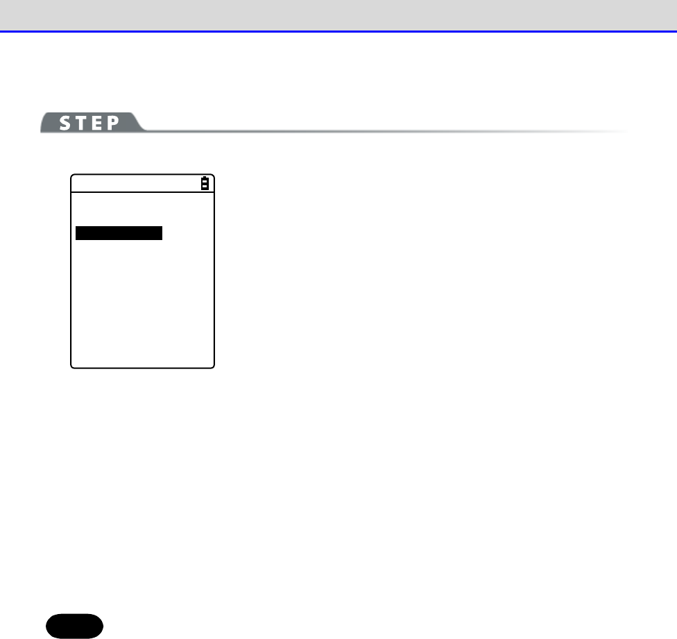
Chapter 4 System Menu 4-5 Network: Network Connection Settings
GTX-221-G User’s Manual
138
■Advanced
You can perform advanced FTP settings.
[System Menu]→[3:Network]→[3:FTP]→[4:Advanced]
< Advanced >
1:Server port
[00021]
2:Mode
Passive
Active
3:Folder
Select the item to be set.
・Server port: Specifies the control port number of the FTP server
・Mode: Specifies the mode
・Folder: Specifies the folder
●Server port
Specifies the control port number of the FTP server.It is set to 21 (00021), a well-known FTP
number, in factory settings.
●Mode
It is set to Passive mode by default.Set it to Active mode if the FTP server does not support
Passive mode.
Hint
The firewall has a setting that denies connection from the outside to the inside.
While this setting is enabled, FTP communication is not available in Active mode.
Using Passive mode allows you to perform communication with an FTP server located
on the other side of the firewall.
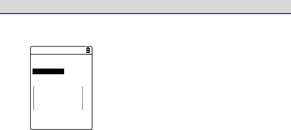
Chapter 4 System Menu 4-5 Network: Network Connection Settings
GTX-221-G User’s Manual
139
●Folder
You can specify the transmission/reception folders of the FTP server.
< Folder >
1:Current
[/(Root) ]
2:Specified
・Current
Select [Current]to display the submenu.
Select the current folder from the following items:
/(Root)
The root folder of the FTP server. The user name folder may be
specified as the root folder, depending on the FTP server.
/(User name)
Sets the user name folder in the root folder of the FTP server
as the current folder.If the user name has not been set, executing
the FTP function (file transmission/reception) will lead to an
error screen.
/(Specified)
Sets the relative path from the root folder set as "Specified"
(see the next item) as the current folder.
・Specified
Select [Specified], and enter the folder name.
The text set here will be added to the FTP method of "CWD". As the
text set here is directly used for FTP communication, the file path
must be correctly entered.
(Ex.) "dir1/dir2/dir3"
Spaces cannot be included in the specified folder.
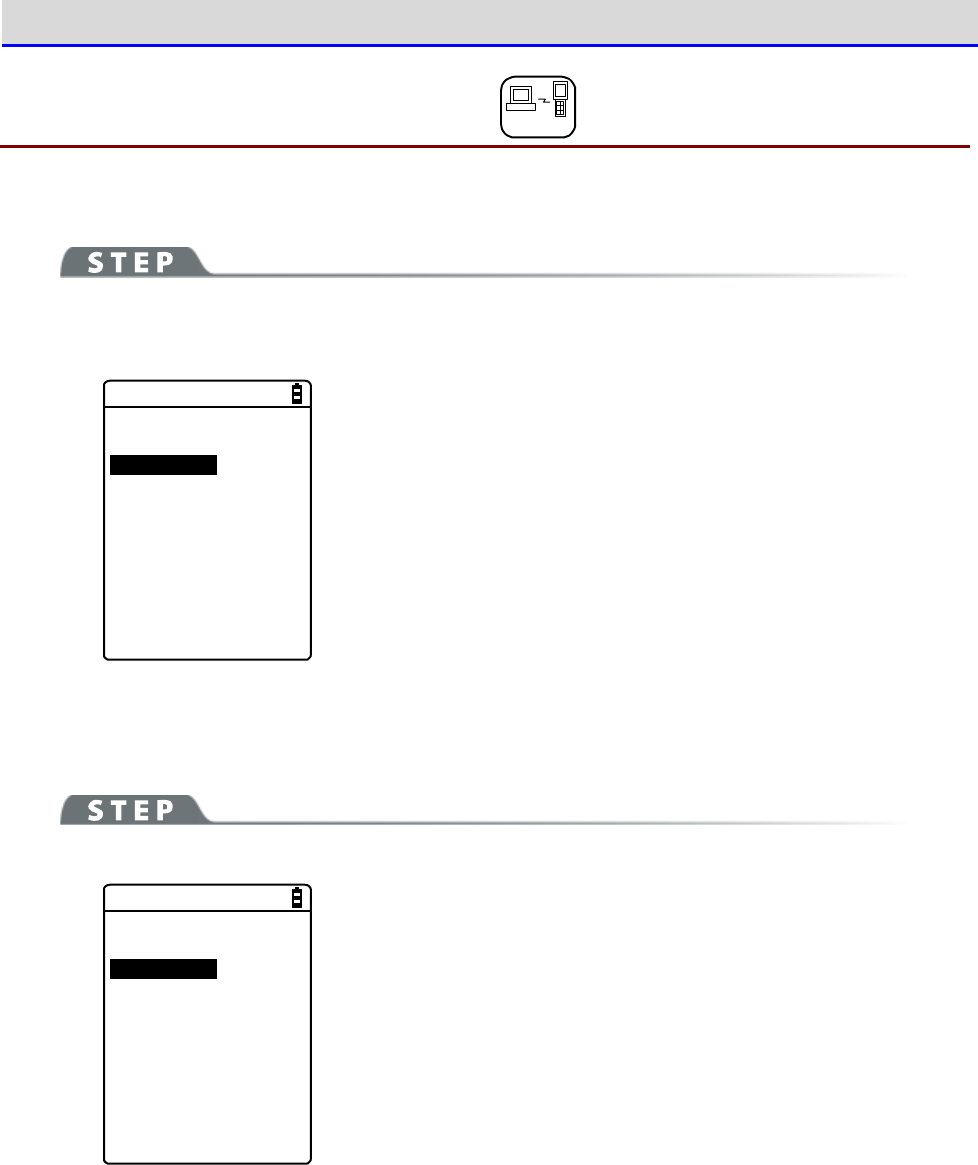
Chapter 4 System Menu 4-5 Network: Network Connection Settings
GTX-221-G User’s Manual
140
4-5-4 DNS: DNS Server Settings DHCP
You can set the address of the DNS server.
[System Menu]→[3:Network]→[4:DNS]
Select the item to be set.
< DNS >
1:Primary
[000.000.000.000]
2:Secondary
[000.000.000.000]
3:Advanced
・Primary: Sets the IP address of the primary DNS server
・Secondary: Sets the IP address of the secondary DNS server
・Advanced: Performs advanced settings for DNS
■Primary
This is used to set the IP address of the primary DNS server.
[System Menu]→[3:Network]→[4:DNS]→[1:Primary]
< DNS >
1:Primary
[000.000.000.000]
2:Secondary
[000.000.000.000]
3:Advanced
Enter the IP address of the primary DNS server.
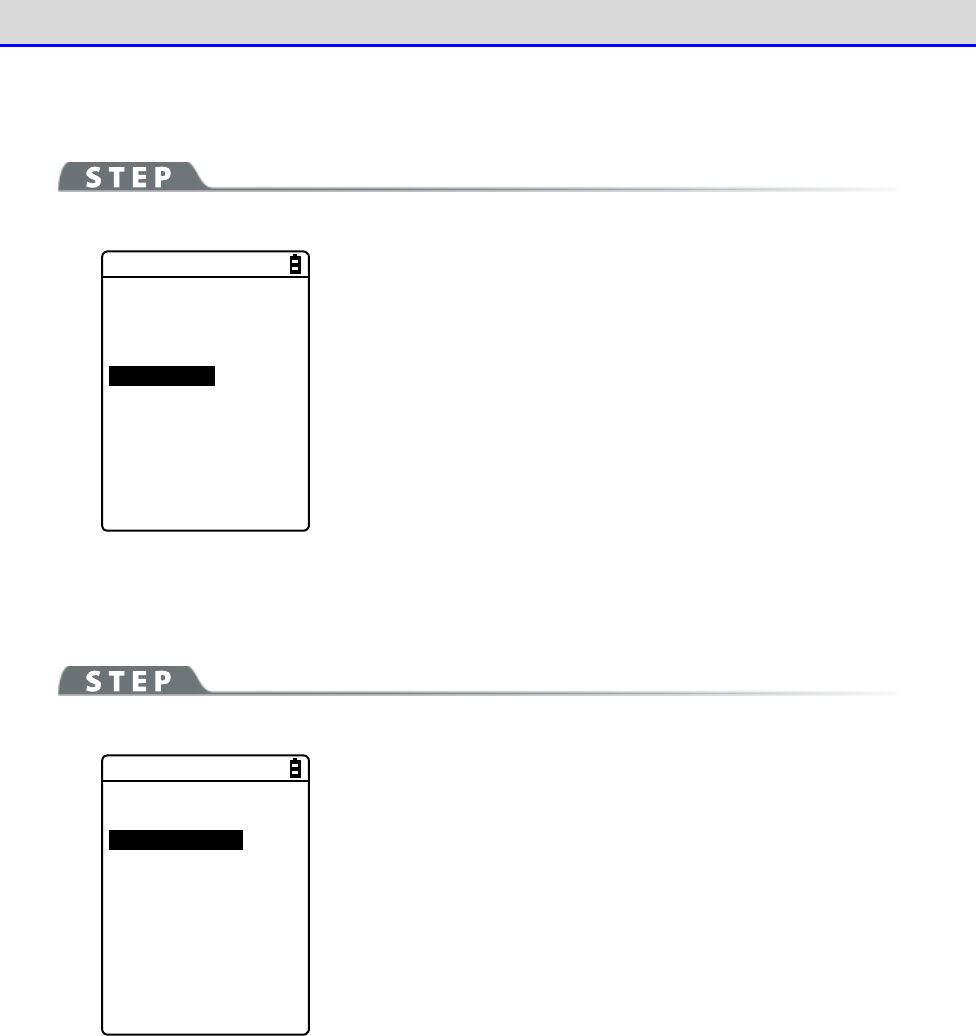
Chapter 4 System Menu 4-5 Network: Network Connection Settings
GTX-221-G User’s Manual
141
■Secondary
This is used to set the IP address of the secondary DNS server.
[System Menu]→[3:Network]→[4:DNS]→[2:Secondary]
< DNS >
1:Primary
[000.000.000.000]
2:Secondary
[000.000.000.000]
3:Advanced
Enter the IP address of the secondary DNS server.
■Advanced
You can perform advanced settings for DNS
[System Menu]→[3:Network]→[4:DNS]→[3:Advanced]
< Advanced >
1:Server port
[00053]
2:Timeout time
[01]sec
3:Trial count
[1]
4:Cache time
[0003]min
Select and set the item.
・Server port
Specifies the control port number of the DNS server. The
well-known port number is 53.
・Timeout time
Sets the response packet latency within 1 - 99 seconds.
・Trial count
Sets the number of retries.If it is set to 0, only one packet will
be sent, and no retry will be performed.
・Cache time
Its setting range is 0 - 9999 minutes.If it is set to 0, the cache
function will be disabled.The maximum number of entries at the
cache table is 8. If the maximum value is exceeded, the old entry
is erased and a new entry is created.
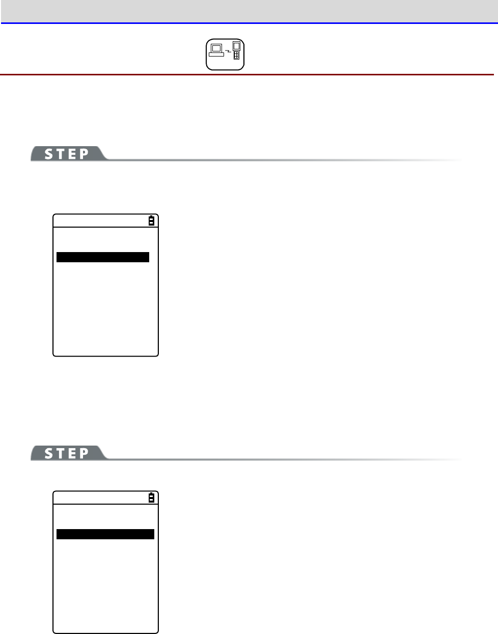
Chapter 4 System Menu 4-5 Network: Network Connection Settings
GTX-221-G User’s Manual
142
4-5-5 SNMP: SNMP Setting DHCP
You can perform various settings for SNMP.
The settings can also be made automatically if the DHCP function is enabled.
[System Menu]→[3:Network]→[5:SNMP]
Select the item to be set.
< SNMP >
1:Community(R/Only)
2:Community(R/W)
3:Trap
4:Advanced
・Community (R/Only): Sets the read-only community
・Community (R/W): Sets the read-write community
・Trap: Sets the Trap community
・Advanced: Performs advanced settings for SNMP
■Community (R/Only)
You can set the read-only community name.
[System Menu]→[3:Network]→[5:SNMP]→[1:Community(R/Only)]
<Community(R/Only)>
1:Community name
[public ]
2:Manager IP address
[000.000.000.000]
Select and set the item.
・Community name
The community name is specified using up to 16 alphanumeric
characters.
The actions allowed by this community name are "Read-Only". GET
and GET-NEXT requests are supported by this community name. When
SET request is performed by this community, an authentication
trap will be sent.
・Manager IP address
Sets the IP address of the SNMP manager that is enabled using the
community name set at[Community name].
When the IP address is set to "000.000.000.000", this community
name is enabled for all the SNMP managers.
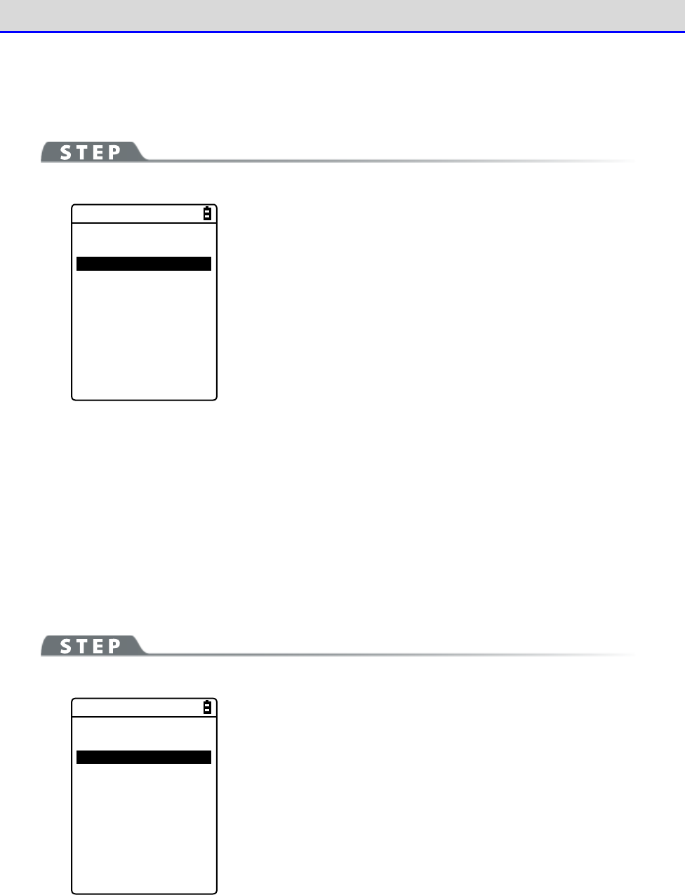
Chapter 4 System Menu 4-5 Network: Network Connection Settings
GTX-221-G User’s Manual
143
■Community (R/W)
You can set the read-write community name.
[System Menu]→[3:Network]→[5:SNMP]→[2:Community(R/W)]
< Community(R/W) >
1:Community name
[private ]
2:Manager IP address
[000.000.000.000]
Select and set the item.
・Community name
The community name is specified using up to 16 alphanumeric
characters.
The actions allowed by this community name are "Read-Write". GET,
GET-NEXT, and SET requests are supported by this community name.
・Manager IP address
Sets the IP address of the SNMP manager that is enabled using the
community name set at[Community name].
When the IP address is set to "000.000.000.000", this community
name is enabled for all the SNMP managers.
■Trap
You can set the Trap community name.
[System Menu]→[3:Network]→[5:SNMP]→[3:Trap]
< Trap >
1:Community name
[Welcat ]
2:Manager IP address
[000.000.000.000]
Select and set the item.
・Community name
You can set the Trap community name. The community name is
specified using up to 16 alphanumeric characters.
・Manager IP address
Sets the IP address of the SNMP manager, which is the transmission
destination of Trap. When the IP address is set to
"000.000.000.000", no trap will be sent.
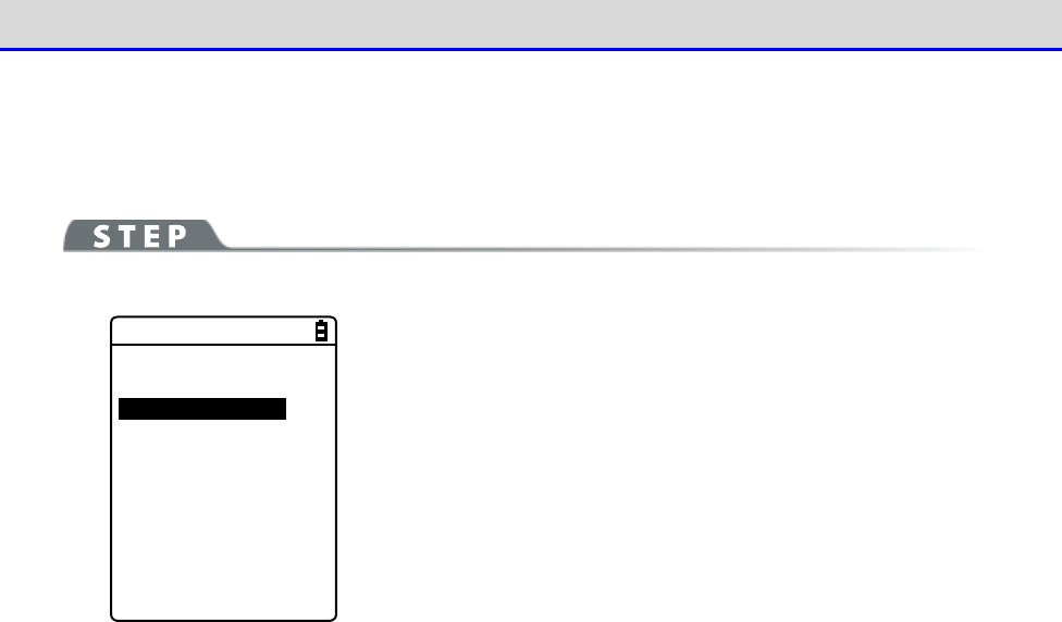
Chapter 4 System Menu 4-5 Network: Network Connection Settings
GTX-221-G User’s Manual
144
■Advanced
You can perform advanced settings for SNMP.
[System Menu]→[3:Network]→[5:SNMP]→[4:Advanced]
< Advanced >
1:Authentic trap
Send
2:Agent port
[00161]
3:Trap port
[00162]
4:Trap retry
[1]
Select and set the item.
・Authentic trap
Sets whether to "Send" Authentic trap when access is found to be
from other than the community name and the manager IP address set
on "1: Community (R/Only)" or "2: Community (R/W)".
This trap is sent to the SNMP manager set on "2: Manager IP
address".
・Agent port
Sets the SNMP manager and the communication port number.
It is set to 161 (00161), a well-known SNMP number, in the factory
settings.
・Trap port
The trap port number for sending the trap.The well-known port
number is 162.
・Trap retry
Specifies the number of times for resending the Trap.
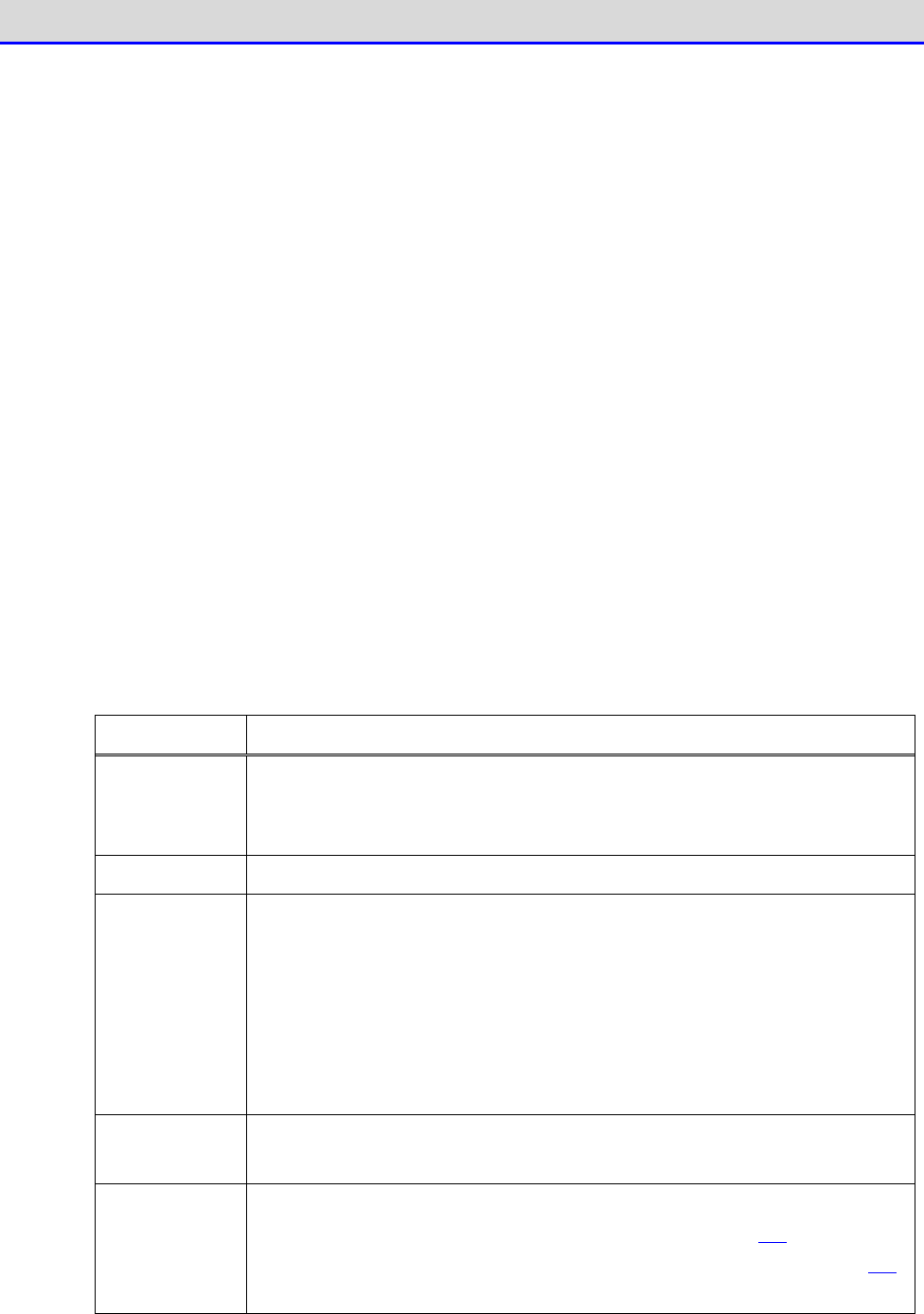
Chapter 4 System Menu 4-5 Network: Network Connection Settings
GTX-221-G User’s Manual
145
●About SNMP
・The Handy Terminal can perform management using "Network Administration Tool" included in
"WebGlider Integration Server" (WGS-001).
・SNMP-PDU (Protocol Data Unit) is compliant with SNMPv1.
・The Handy Terminal manages the objects of the following MIB groups:
[1.3.6.1.2.1.1] MIB2-System
[1.3.6.1.2.1.2] MIB2-Interfaces
[1.3.6.1.2.1.4] MIB2-IP
[1.3.6.1.2.1.5] MIB2-ICMP
[1.3.6.1.2.1.6] MIB2-TCP
[1.3.6.1.2.1.7] MIB2-UDP
[1.3.6.1.2.1.11] MIB2-SNMP
[1.3.6.1.4.1.12392] Welcat Enterprise MIB
Welcat Enterprise MIB is described in ASN.1 format.
Welcat Enterprise MIB is included in "WebGlider Integration Server" (for more information,
contact our sales office).
・Supported Traps
Trap Description
Cold Start Sent during communication start after MIB is initialized.MIB is ini-
tialized upon power on.
However, initialization will not be performed
when recovered from resume.
Warm Start When sent during a communication start other than Cold Start.
*1
Link up Sent when the Handy Terminal has been synchronized with the access point.
However, Link up is not sent when synchronization with the access point
is first realized (ColdStart and Warm Start were sent).It is also sent
on reaching synchronization when the Handy Terminal enters from out
side
to inside the range of communication, or when synchronization with a new
access point is reached by roaming (same timing with signal
SIGRFU_INSYNC).
Link down Sent upon termination of communication.However, it is not sent when
outside the range.
Authentication
When an attempt is made to access the Handy Terminal
, this trap is sent
to the IP address set on "Trap-Manager IP address" (P. 143)
However, it
is sent only when "Send" is checkmarked at "Trap-Authentic trap" (P.144
)
on the system menu.
*1
Even if the MIB-related settings (such as IP address, subnet mask, default gateway) are
changed, MIB will not be initialized. Therefore, instead of Cold Start, Warm Start will
be sent.
To initialize MIB, restart the Handy Terminal.
Chapter 4 System Menu 4-6 Receive: Receiving Files
GTX-221-G User’s Manual
146
4-6 Receive: Receiving Files
4-6-1 Receive: Receiving Files by WLAN/Bluetooth/Infrared
Communication (IrDA)
Upon reception, confirm the following items (all received files are saved in the F drive):
●When Using WLAN Communication
•
The communication settings (such as IP address, SSID, and security settings) between the
Handy Terminal and the access point have been configured correctly.
•
The access point and the PC have been powered up.
•
The access point and the PC have been correctly set and connected.
•
The access point is operating normally.
•
The FTP server of "Network Administration Tool" included in "WebGlider Integration Server"
(WGS-001) has been started on the PC side.
•
The FTP settings (such as host name, user name) of the Handy Terminal have been configured
correctly.
●When Using Bluetooth Communication
•
The PC has been powered up
•
The Bluetooth communication adapter has been inserted correctly into the PC.
•
BluePorter-V (WLF-003: Optional) has been started
•
BluetoothManager is ON, and the BluetoothManager icon displayed in the task tray of the
PC has become white.
•
As the default device of the Handy Terminal, the PC on the sending side has been registered
(see "4-9-3 Bluetooth: Registering and Setting the Bluetooth Device" (P.169))
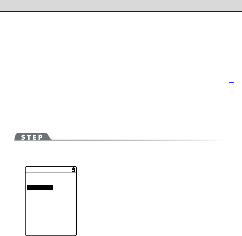
Chapter 4 System Menu 4-6 Receive: Receiving Files
GTX-221-G User’s Manual
147
●When Using Infrared Communication (IrDA)
Upon reception, confirm the following items:
■When the Sending Side Is a PC
・The PC has been powered up
・The "BluePorter-V" (WLF-003: Optional) has been started on the PC.
・The Handy Terminal has been set to the USB communication unit, and infrared communication
has been enabled (see "3-4 Building Infra-red Communication (IrDA) Environment" (P.81))
■When the sending side is XIT-2xx series
・Can be sent using "wait (HT)"
・ Communicate with reference to communication between Handy Terminals in "3-4 Building
Infra-red Communication (IrDA) Environment" (P.81)
[System Menu]→[4:Receive]
Select the communication means for reception.
< Device type >
1:WLAN
2:Bluetooth
3:IrDA
Select the reception method.
・WLAN
・Bluetooth
・IrDA
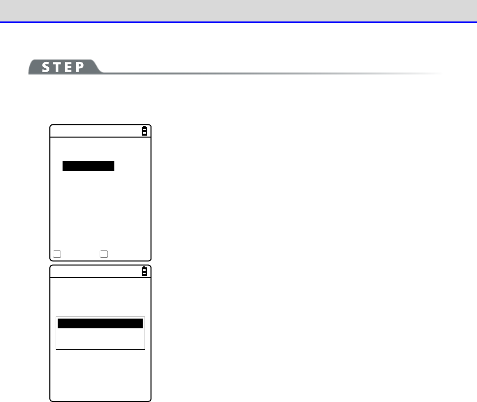
Chapter 4 System Menu 4-6 Receive: Receiving Files
GTX-221-G User’s Manual
148
■Receiving Files (WLAN)
[System Menu]→[4:Receive]→[1:WLAN]
①
Get the file list, and select the files to be received.
< File list >
SAMPLE1.OUT
SAMPLE2.OUT
Receive Menu
F1 F2
Select the files to be received by checkmarking their names.
Press the【F1】key to display the reception confirmation dialog.
In such as case, if there is no checkmarked file, the selected file
will be received.
Select[Yes]/[No].
Full name
All checks applied
All checks removed
Press the【F2】key to display the submenu for operating the file
list.
Change the settings as needed.
・Full name
Displays the full name of each selected file.
・All checks applied
Selects all the checkboxes in the file list.
・All checks removed
Clears all the checkboxes in the file list.

Chapter 4 System Menu 4-6 Receive: Receiving Files
GTX-221-G User’s Manual
149
②
Reception starts.
< 受信中 >
sam p le1 .OU T
000010 / 000021
The reception status is displayed on the screen.
A file named
“SAMPLE1.OUT”
already exists.
Would you like to
replace it?
YES NO
If there are files with the same names as the files to be received,
an overwriting confirmation dialog will be displayed.
Select[Yes]/[No].
③
Reception takes place.
Completed
OK
Upon completion of reception, [ (Number of Reception Suc-
cesses/Number of Checks)]will be displayed in the message box.
Press the【ENT】key.
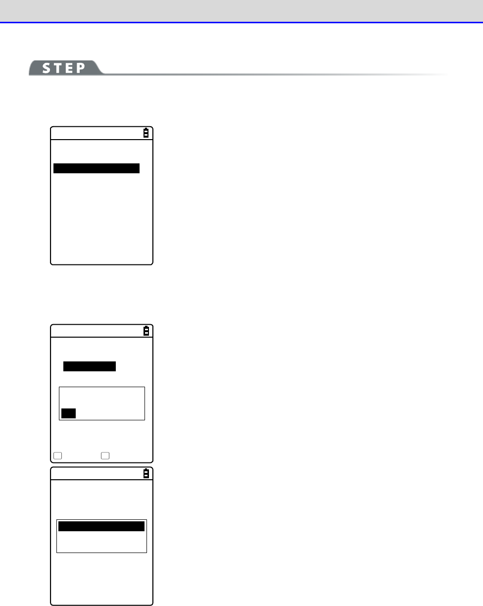
Chapter 4 System Menu 4-6 Receive: Receiving Files
GTX-221-G User’s Manual
150
■Receiving Files (Bluetooth/IrDA)
[System Menu]→[4:Receive]→[2:Bluetooth]/[3:IrDA]
①
Select the reception method.
< Receiving method >
1:Select from list
2:wait(PC)
3:wait(HT)
Select "Select from list" to get the file list from the sending side.
The receiving side can select the files to be received from the
list.
→
Procedure②
Select "2:Wait (PC)"/"3:Wait (HT)" to enter the reception wait
state immediately. If the sending side is a PC, select "2:Wait
(PC)"; if it is XIT-2xx, select "3: Wait (HT)"Files to be received
depend on the sending side.
→
Procedure③
* "Wait (PC)" is a function that can be used by BluePorter in
Bluetooth communication. It cannot be used by BluePorter-V.
②Select the files to be received.
< File list >
SAMPLE1.OUT
SAMPLE2.OUT
Execute Menu
F1 F2
Would you like to
receive it?
YES NO
Select the files to be received by checkmarking their names, and
then press the【F1】Key.
The reception confirmation dialog is displayed.If there is no
checkmarked file, the selected file will be received.
Select[Yes]/[No].
Full name
All checks applied
All checks removed
Press the【F2】key to display the submenu for operating the file
list.
Change the settings as needed.
・Full name
Displays the full name of each selected file.
・All checks applied
Selects all the checkboxes in the file list.
・All checks removed
Clears all the checkboxes in the file list.
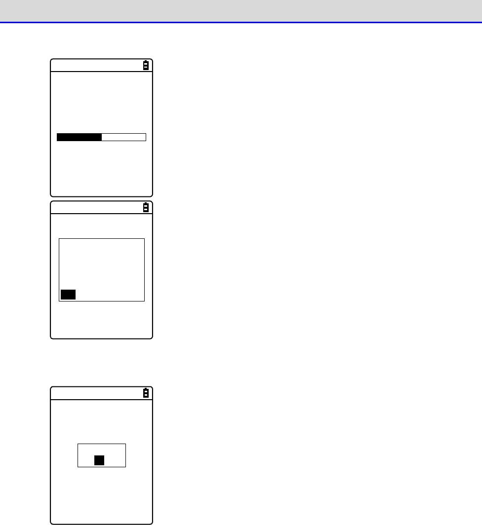
Chapter 4 System Menu 4-6 Receive: Receiving Files
GTX-221-G User’s Manual
151
③
Reception starts.
< Receiving >
sample1.OUT
000010 / 000021
The reception status is displayed on the screen.
A file named
“SAMPLE1.OUT”
already exists.
Would you like to
replace it?
YES NO
If there are files with the same names as the files to be received,
an overwriting confirmation dialog will be displayed.
Select[Yes]/[No].
④
Reception takes place.
Completed
OK
Upon completion of reception, [ (Number of Reception Suc-
cesses/Number of Checks)]will be displayed in the message box.
Press the【ENT】key.
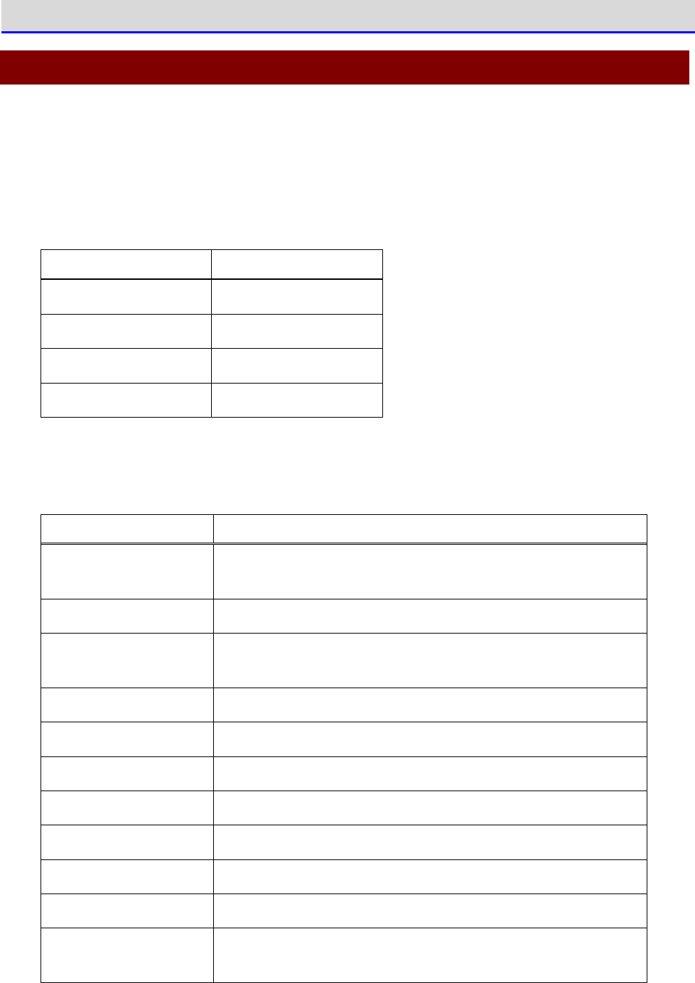
Chapter 4 System Menu 4-7 File: Executing, Uploading, and Deleting Files
GTX-221-G User’s Manual
152
4-7 File: Executing, Uploading, and Deleting Files
Use this category to look for the target file and perform such operations as executing, uploading,
and deleting it.
Select the file to operate from a list classified by file type in each drive. File types are
determined by their extensions (three letters that follow a period (.) after each filename)
and classified as follows:
File type
Extension
Application program
OUT
Graphic data
BMP, JPG, JPEG, PNG
Audio data WAV, SFL
Data
Other than above
You can perform the operations shown below; there are operations associated with specific file
types and operations you can perform on all files.
Operation
Description
Execute
※1
Start up an application program. You can perform this opera
tion
only when the file type is "Application".
View
※2
Display graphic data.
Play
※3
Play an audio file. You can perform this operation only when
the file type is "Audio".
Properties
Display information about a file.
Upload
Upload files.
Delete
Delete files.
All checks applied
Mark all the checkboxes in the file list.
All checks removed
Unmark all the checkboxes in the file list.
Copy to FDrive Copy files to the F drive.
Copy to SDrive Copy files to the S drive.
Copy to RDrive
(microSD)
Copy files to the R drive (microSD).
※1
You can not operate files in the S drive.
Chapter 4 System Menu 4-7 File: Executing, Uploading, and Deleting Files
GTX-221-G User’s Manual
153
※2
Supported graphic data is as follows:
Format
BMP, JPG, JPEG, PNG
Size
Maximum 480×640 pixels
(Display area: 240×296 pixels)
※3
Supported audio data is as follows:
Extension WAV
Format Windows standard WAVE format
Audio sampling rate
8000/11025/16000/22050/44100/48000[Hz]
Channel Monophonic
Audio sample size 16bit
Audio method PCM
Extension SFL
Format Audio file list (text format)
Maximum number of
files listed
32
Explanation
By using a SFL file, you can continuously play multiple audio
files.
List filenames in a file list by separating each with a line
feed. A maximum of 32 filenames can be listed.
Listed audio files should be stored in the product i
n advance.
Each file whose name is listed in a file list is played only
once.
If an error occurs during playback, the subsequent audio files
will not be played.
You cannot list names of other SFL files in a SFL file.
Description example
ALARM_MELODY.WAV (line feed)
LOCATION_3F_2.WAV (line feed)
SHIP_ERROR.WAV
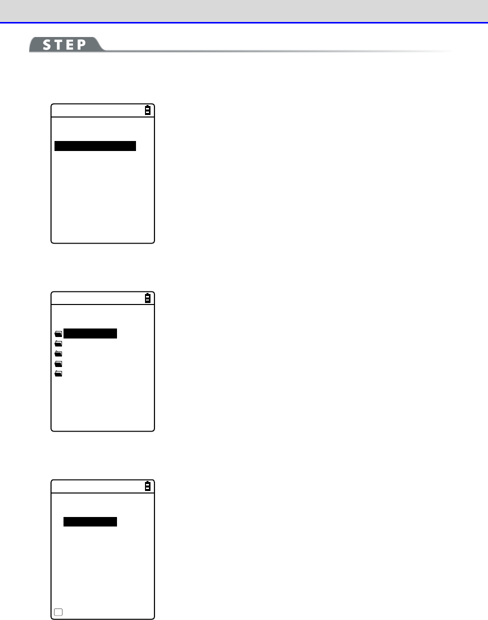
Chapter 4 System Menu 4-7 File: Executing, Uploading, and Deleting Files
GTX-221-G User’s Manual
154
[System Menu]→[5: File]
①
Select the drive.
< Drive type >
1:FDrive
2:SDrive
3:RDrive(microSD)
Select the drive to operate.
②
Select the file type (for a drive other than the RDrive).
< File type >
Application
Data
Audio
Graphic
All type
Select the type of file to operate. When "All type" is selected,
regardless of file type, all the files stored in the drive will be
included.
③
Mark the file to operate.
< FDrive >
132X128.JPG
COPAN1.JPG
COPAN2.JPG
HABANERO.JPG
KOUME1.JPG
KOUME2.JPG
MAKE.TXT
Menu
F1
Select the file and press the【ENT】key to mark and unmark the checkbox
for that file.
There are two types of operation: operation to target the marked
file and operation to target the selected file.
Chapter 4 System Menu 4-7 File: Executing, Uploading, and Deleting Files
GTX-221-G User’s Manual
155
④
Operate the file.
Execute
Properties
Upload
Delete
All checks applied
All checks removed
Copy to SDrive
Copy to RDrive
(Screen displayed
when the FDrive is
selected)
Press the【F1】key to display the file operation submenu.
Note: Depending on the file to select, the following submenu items
change:
・Execute: Execute an application program.
・Play: Play audio data.
・View: Display graphic data.
・Properties: Display detailed information of a file.
・Upload: Upload files to a PC or another terminal.
・Delete: Delete files.
・All checks applied: Select all files.
・All checks removed: Deselect all files.
・Copy to SDrive: Copy files to the S drive.
・Copy to RDrive(microSD): Copy files to the R Drive.
C
a
u
t
i
o
n
Depending on the selected drive, copy destination drives to be displayed are
different. Note that the selected drive cannot be set as a copy destination.
Chapter 4 System Menu 4-7 File: Executing, Uploading, and Deleting Files
GTX-221-G User’s Manual
156
■Execute: Execute an Application Program
[System Menu]→[5:File]→[Application]→Select the drive→[F1 Menu]
→[Execute]
Execute the selected file.
Would you like to
register with
“Auto execute”?
YES NO
The file being selected (highlighted) will be executed (regardless
of whether its checkbox is marked).
Press the【ENT】key to execute the file.
If the application program to execute is not registered in Auto
execute, a registration confirmation dialog box appears.
To terminate the application program executed, perform the op-
eration specified for each application program. After termination,
whether to display the system menu again or to turn the main unit's
power OFF depends on the application program.
If the battery pack runs out of power during operation, the main
unit's power is turned off after displaying an alarm.
If you want to forcibly terminate the application program, hold down
the【PW】key for 10 seconds while the application program is running.
■Play: Play Audio Data
[System Menu]→[5: File]→[Audio]→Select the drive→[F1 Menu]→[Play]
Play the audio data.
< Audio >
Playing ...
Stop
The audio file being selected will be played (regardless of whether
its checkbox is marked).
Press the【C】key to stop playing the file.
■View: Display Graphic Data
Chapter 4 System Menu 4-7 File: Executing, Uploading, and Deleting Files
GTX-221-G User’s Manual
157
[System Menu]→[5:File]→ Select the drive →[Graphic]→[F1 Menu]→[View]
Display and check the graphic data.
The image in the file being selected (highlighted) will be displayed
(regardless of whether its checkbox is marked).
Press any key to return to the "File Operation Menu".
■Properties: Display Detailed Information of a File
[System Menu]→[5:File]→ Select the drive → Select the file type →
[F1 Menu]→[Properties]
Check detailed information of the file.
< File Property >
Name
SAMPLE1.OUT
Type[Application]
Library[1.00]
Size[00000000]Bytes
Modified
2012/01/01
00:00:00
The following information will be displayed:
・Name
・Type
・Size
・Modified
Information about the file being selected (highlighted) will be
displayed (regardless of whether its checkbox is marked).
Press any key to return to the <File> screen.
Chapter 4 System Menu 4-7 File: Executing, Uploading, and Deleting Files
GTX-221-G User’s Manual
158
■Upload: Upload Files to a PC or Another Terminal
Check the following before upload:
●To use WLAN communication
•
The communication settings of the Handy Terminal and the access point are correctly
configured (IP address, SSID, security settings, etc).
•
The power is turned ON for the access point and the PC.
•
The access point and the PC are correctly configured and connected.
•
The access point operates correctly.
•
FTP server software is running on the PC.
•
The FTP settings (host name, user name, etc) of the Handy Terminal are correctly configured.
●To use Bluetooth communication
•
The PC's power is turned ON.
•
A Bluetooth communication adapter is correctly inserted in the PC.
•
BluePorter-V is running.
•
BluetoothManager is turned ON and its icon is displayed in the taskbar on the PC.
•
BluetoothManager's icon is turned white.
•
The PC on the uploading side is registered as the default device for the Handy Terminal.
●To use infrared (IrDA) communication
■
When the uploading side is the PC
・Turn the PC's power ON.
・Start up "BluePorter-V" (WLF-003: optional) on the PC.
・Place the Handy Terminal in the USB communication unit and prepare infrared communication.
■
When the uploading side is a XIT-2xx series product
・Uploading becomes ready when "wait (HT)" is selected.
(For details on how to configure BluePorter-V, see "3-2 Configuring BluePorter-V" in "File
Transfer Utility BluePorter-V Operation Guide".)
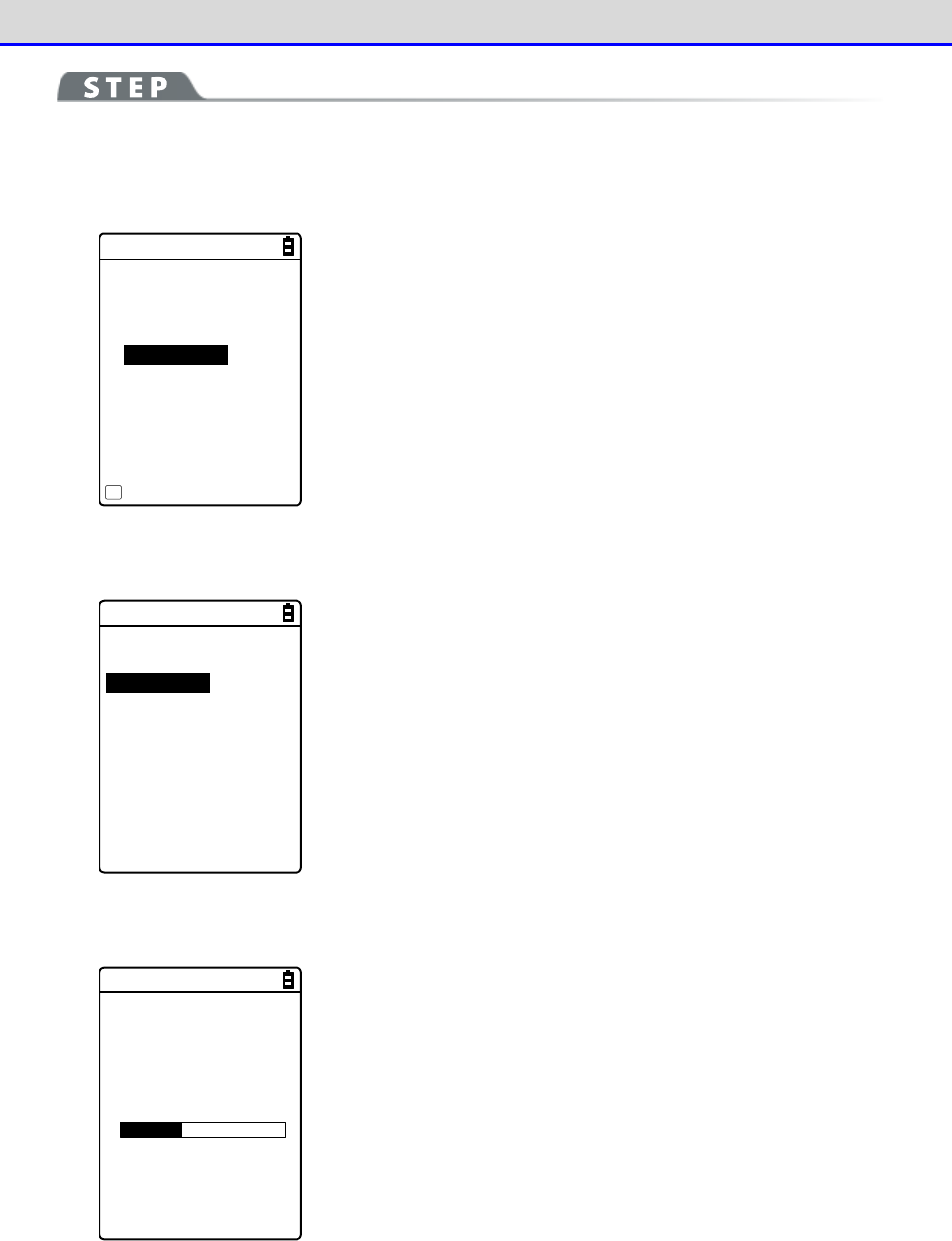
Chapter 4 System Menu 4-7 File: Executing, Uploading, and Deleting Files
GTX-221-G User’s Manual
159
[System Menu]→[5:File]→ Select the drive→Select the file type →[F1 Menu]
→[Upload]
①
The marked file(s) will be uploaded.
< FDrive >
123X128.JPG
COPAN1.JPG
SAMPLE1.OUT
SAMPLE2.OUT
HABANERO.JPG
MAKE.TXT
Menu
F1
Select and mark the file(s) to upload.
If there is no marked file, the file being selected will be uploaded.
Press the【F1】key, select [Upload], and press the【ENT】key.
②
Select the upload method.
< Device type >
1:WLAN
2:Bluetooth
3:IrDA
Select the upload method.
・WLAN
・Bluetooth
・IrDA
③
Uploading will start.
< 送信中 >
sam p le1 .OU T
0847872 / 2101161
The upload status is displayed on the screen.
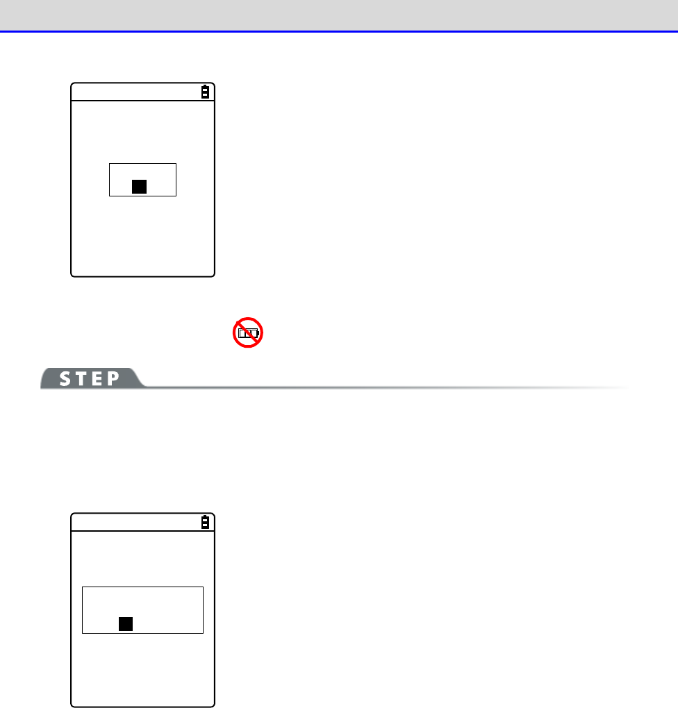
Chapter 4 System Menu 4-7 File: Executing, Uploading, and Deleting Files
GTX-221-G User’s Manual
160
④
Finish the uploading process.
Completed
OK
When the uploading process becomes complete, "(# of successfully
uploaded files/# of marked files)" will be displayed in the message
box.
Press the【ENT】key.
■Delete: Delete Files
[System Menu]→[5:File]→ Select the drive → Select the file type →
[F1 Menu]→[Delete]
Delete the marked file(s).
If there is no marked file, the file being selected (highlighted) will be deleted.
Would you like to
delete this file?
YES NO
< File delete >
A confirmation dialog box appears.
Select [Yes] or [No].
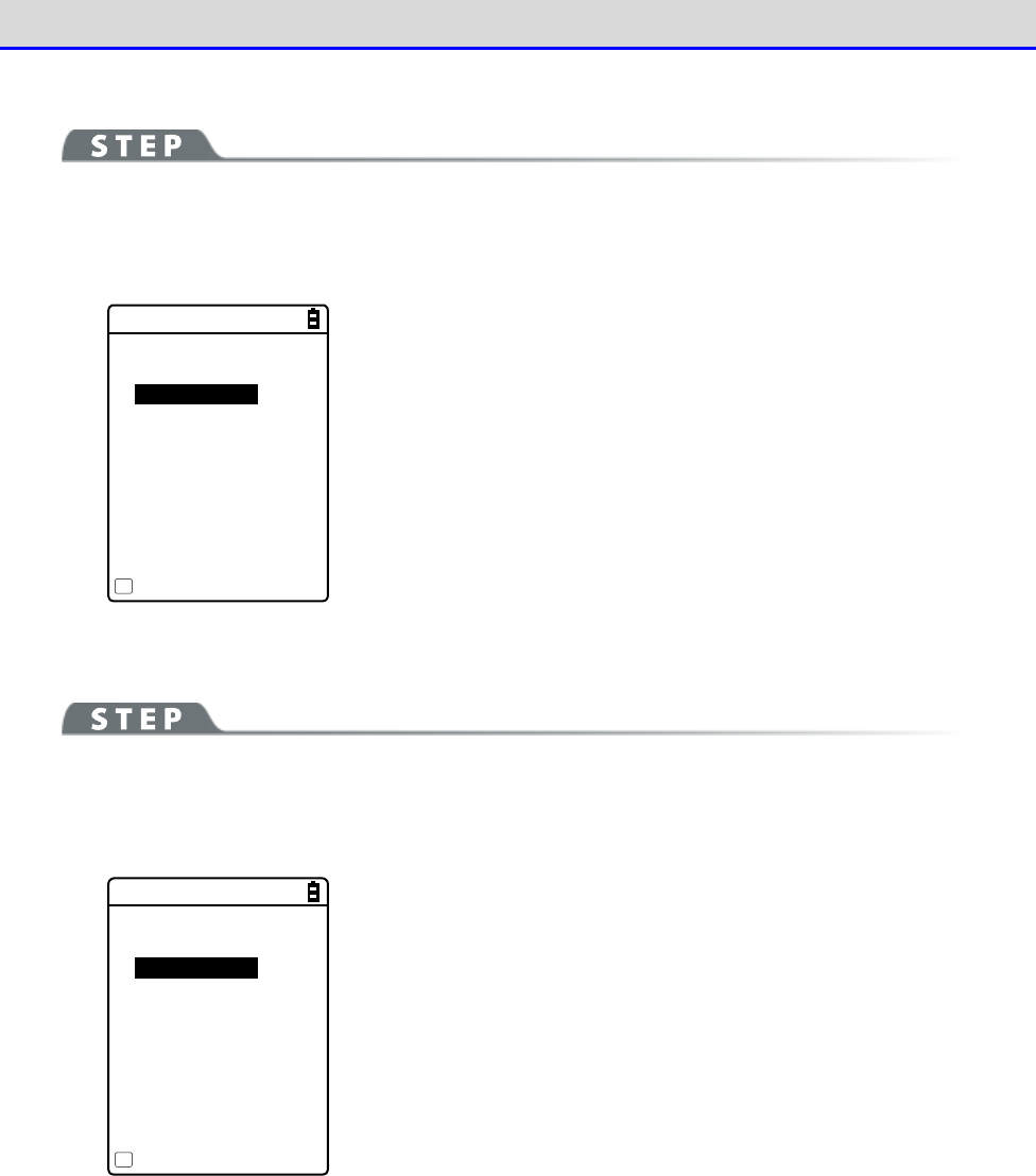
Chapter 4 System Menu 4-7 File: Executing, Uploading, and Deleting Files
GTX-221-G User’s Manual
161
■All Checks Applied: Select All Files
[System Menu]→[5:File]→ Select the drive → Select the file type →
[F1 Menu]→[All checks applied]
All the checkboxes will be marked.
< File >
132X128.JPG
COPAN1.JPG
COPAN2.JPG
HABANERO.JPG
KOUME1.JPG
KOUME2.JPG
MAKE.TXT
Menu
F1
■All Checks Removed: Deselect All Files
[System Menu]→[5:File]→ Select the drive → Select the file type →
[F1 Menu]→[All checks removed]
All the checkboxes will be unmarked.
< File >
132X128.JPG
COPAN1.JPG
COPAN2.JPG
HABANERO.JPG
KOUME1.JPG
KOUME2.JPG
MAKE.TXT
Menu
F1
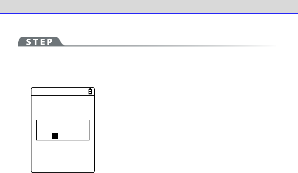
Chapter 4 System Menu 4-7 File: Executing, Uploading, and Deleting Files
GTX-221-G User’s Manual
162
■Copy to the Specified Drive
[System Menu]→[5:File]→ Select the drive → Select the file type →
[F1 Menu]→ Select the copy destination drive
Copy files to the specified drive.
Would you like to
copy this file?
YES NO
< File Copy >
A confirmation dialog box appears.
Select [Yes] or [No].
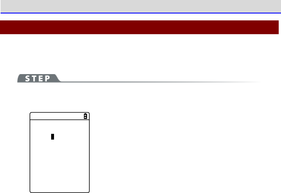
Chapter 4 System Menu 4-8 ID: Setting the Terminal Identification ID
GTX-221-G User’s Manual
163
4-8 ID: Setting the Terminal Identification ID
Use this category to set an ID number for terminal identification to each product. Set a number
unique to each product.
[System Menu]→[6: ID]
Set an ID unique to your terminal.
< ID >
ID [000]
You can enter an ID number in the range 000-999.
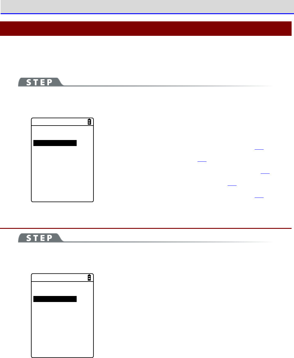
Chapter 4 System Menu 4-9 Device: Setting Hardware Functions
GTX-221-G User’s Manual
164
4-9 Device: Setting Hardware Functions
Use this category to set hardware devices such as a barcode Handy Terminal and keys. Setting
items in the device category are classified by device type.
[System Menu]→[7: Device]
Select the hardware device to configure.
< Device >
1:Barcode
2:Key
3:Bluetooth
4:Display
5:Tone/Vibrator
Select the item to set.
・Barcode: Configure the barcode Handy Terminal (P.164).
・Key: Set the key operation (P.168).
・Bluetooth: Register and Set the Bluetooth device(P.169).
・Display: Set the backlight luminosity(P.177).
・Tone/Vibrator: Set the tone, LED, and vibrator(P.178).
4-9-1 Barcode: Configuring the Barcode Scanner
[System Menu]→[7: Device]→[1: Barcode]
Select the barcode Handy Terminal function to set.
< Barcode Scanner >
1:Trigger mode
2:Version
3:Picklist mode
4:Inverse(1D)
Make a selection from the following items:
・Trigger mode: Set the image Handy Terminal
operating conditions.
・Version: Display the version of decoding.
・
Picklist mode: Set the Picklist mode (targeted scan function).
・ Inverse(1D): Set the scanning of black-and-white-inverted
barcode.
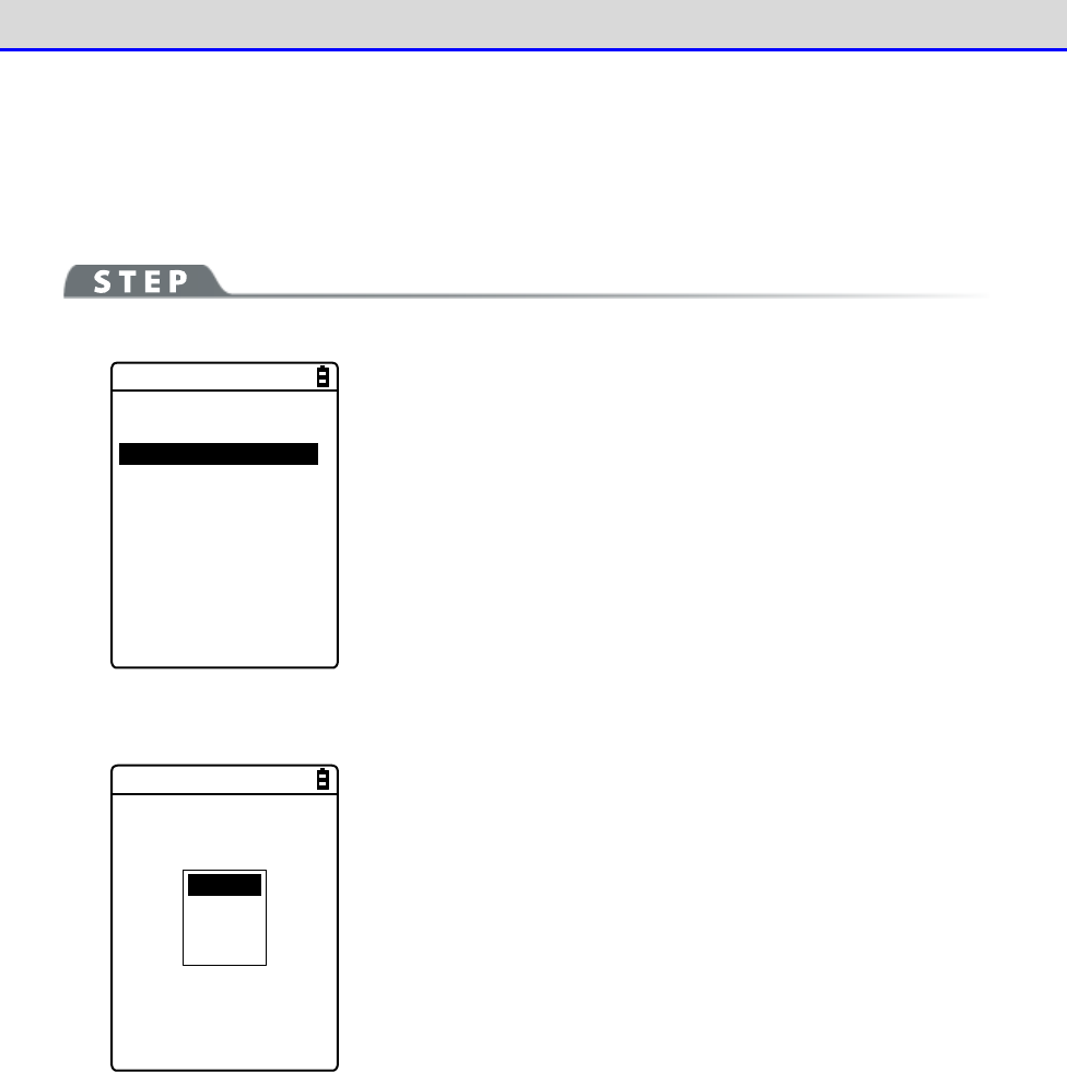
Chapter 4 System Menu 4-9 Device: Setting Hardware Functions
GTX-221-G User’s Manual
165
■Trigger Mode
Use this item to set the irradiation time.
This setting is enabled only in application programs using "Trigger mode" for barcode scanning.
[System Menu]→[7: Device]→[1: Barcode]→[1: Trigger mode]
< Trigger mode >
1:Trigger operation
[Normal]
2:Power saving
[Full]
3:Irradiation time
[20]sec
①Select[Trigger operation].
Normal
Double
Release
Auto
Set the trigger key operation and the irradiation pattern. You can
scan barcodes while laser light is being irradiated (lighted).
・Normal
Press the Trigger key to irradiate laser light.
・Double
Press the Trigger key to make laser light start blinking. Press
the key again to irradiate laser light.
・Release
Press the Trigger key to make laser light start blinking, and
release the key to irradiate laser light.
・Auto
Automatically irradiate laser light regardless of trigger
operation.
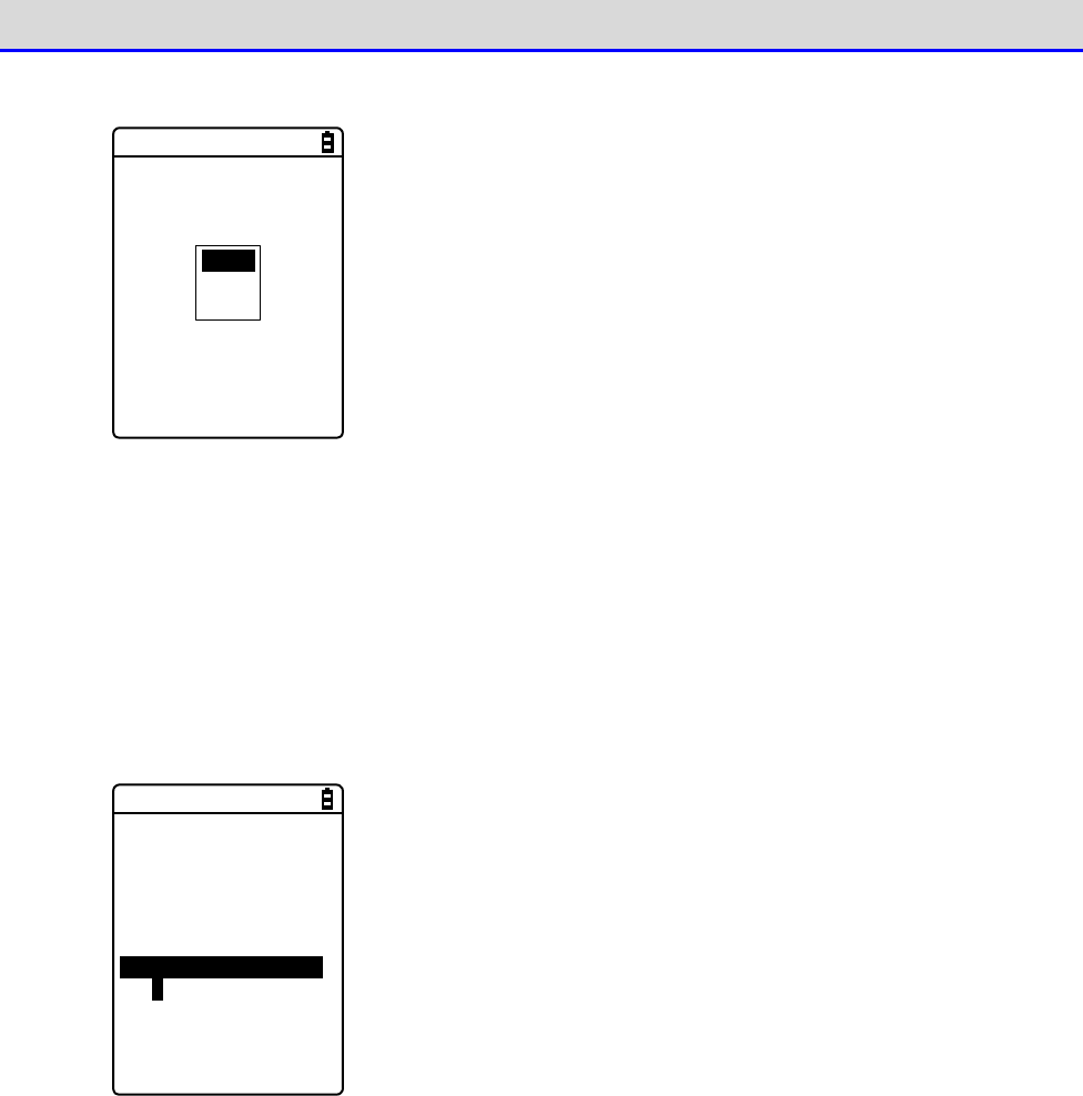
Chapter 4 System Menu 4-9 Device: Setting Hardware Functions
GTX-221-G User’s Manual
166
②Select[Power saving].
Full
Quick
None
Make a setting to suppress power consumption during scan.
・Full
Automatically turn the laser light off after finishing a barcode
scan and stop supplying power to the Handy Terminal section, too.
The power consumption can be reduced, but it takes time to start
the next scan.
・Quick
Automatically turn the laser light off after finishing a barcode
scan but continue supplying power to the Handy Terminal section.
The power consumption is a little greater than when Full is
selected, but you can smoothly proceed to the next scan.
・None
Do not use the Power saving mode.
③Select the[Irradiation time].
< Trigger mode >
1:Trigger operation
[Normal]
2:Power saving
[Full]
3:Irradiation time
[20]sec
Set a time period until the laser light is automatically turned OFF.
You can set a value in the range 00-60 seconds.
When 00sec. is set, the laser light will not be turned OFF and
continue to be irradiated.
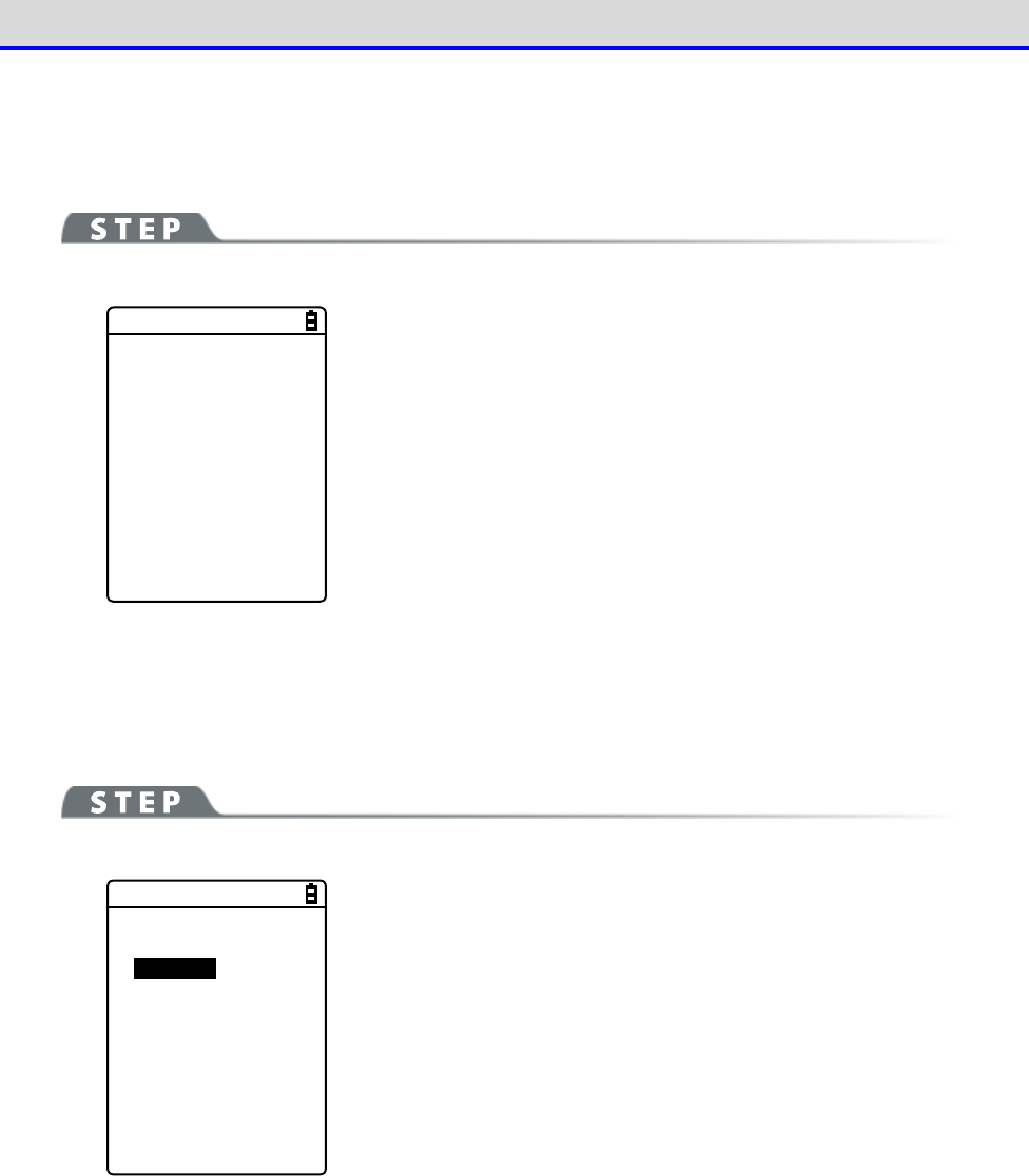
Chapter 4 System Menu 4-9 Device: Setting Hardware Functions
GTX-221-G User’s Manual
167
■Version
Display the version of decoding.
[System Menu]→[7: Device]→[1: Barcode]→[2: Version]
< Version >
PAAAAC07-001-N02 4
620
■Picklist Mode
Set the Picklist mode (targeted scan function).
[System Menu]→[7: Device]→[1: Barcode]→[3: Picklist mode]
< Picklist mode >
Disabled
Enabled
Select between "Enabled" and "Disabled".
・Enabled
Scan symbols in the scan area according to their priorities. The
center of the aimer is the easiest area to scan symbols.
・Enabled
Scan only barcodes in the center of a cross aiming pattern.
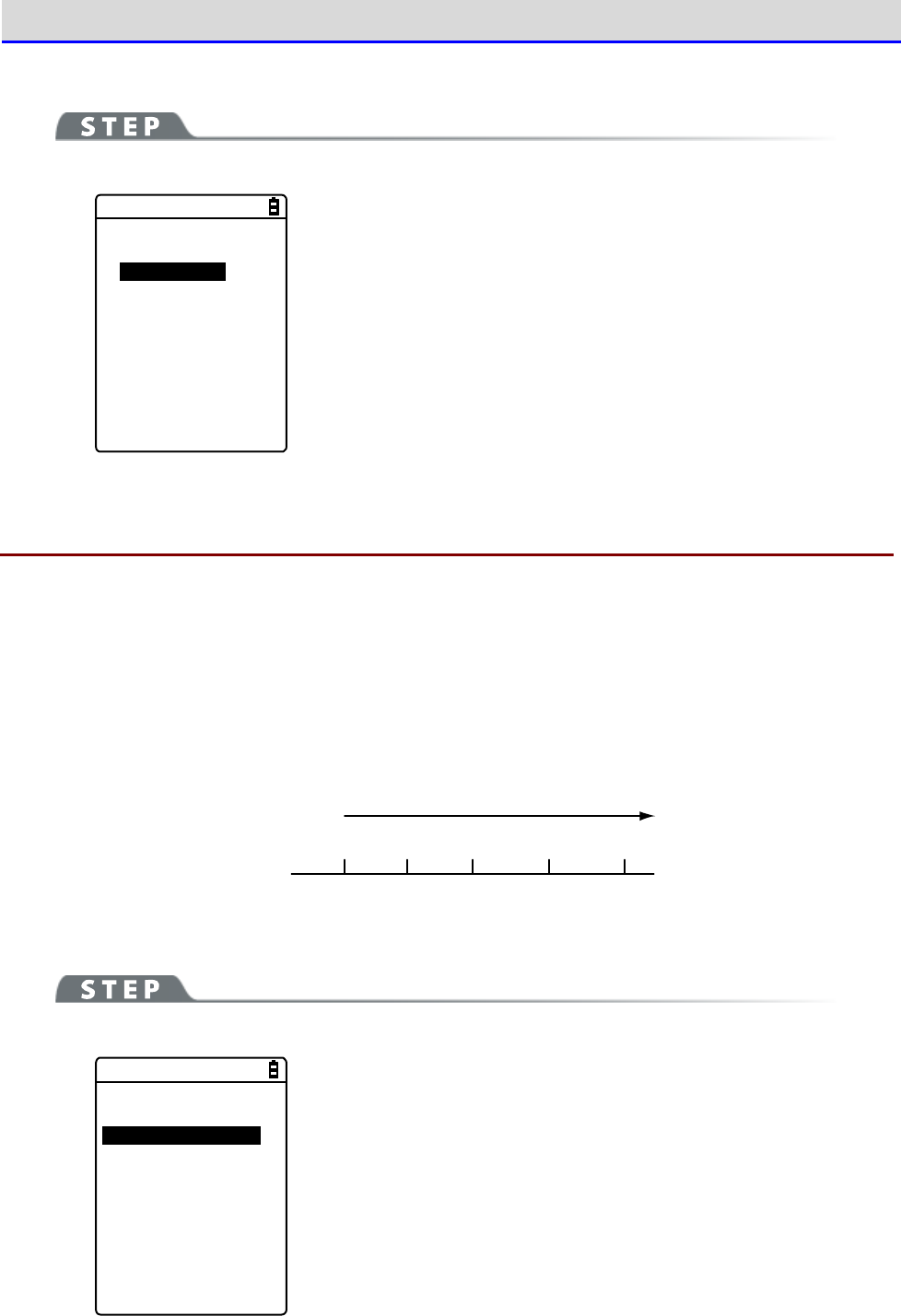
Chapter 4 System Menu 4-9 Device: Setting Hardware Functions
GTX-221-G User’s Manual
168
■Inverted barcode
[System Menu]→[7: Device]→[1: Barcode]→[4: Inverse(1D)]
< Inverse(1D) >
Regular only
Inverse only
Auto detect
Set the scanning of inverted barcodes.
・Regular only
Scan barcodes where the bar is black and the space is white.
・Inverse only
Scan inverted barcodes where the normal black bar is white and
the normal white space is black.
・Auto detect
Scan both regular and inverted barcodes.
4-9-2 Key: Setting the Key Repeat
By holding one of the arrow keys (【
⊳
】【
】【
】【
】), you can repeat inputting that key while
doing so.
This section describes how to set the time between when a arrow key starts to be held down and
when the first key-input repetition is performed (Key repeat delay) and how to set the interval
of subsequent key-input repetitions (Key repeat rate).
Example: When the key repeat delay is set to 1 second. and the key repeat rate is set to 500
milliseconds.
Start holding
the key
First
key-input
Second
key-input
Third
key-input
D
u
r
i
n
g
h
o
l
d
i
n
g
t
h
e
k
e
y
↑ ↑ ↑ ↑
1
second
1.5
second
0.5
second
0
second
2
second
[System Menu]→[7: Device]→[2: Key]
< Key >
1:Key repeat delay
[0500] ms
2:Key repeat rate
[0100] ms
The effective range is 0100-1000 milliseconds.
When 0000 milliseconds is set, it is prohibited to repeat key input.
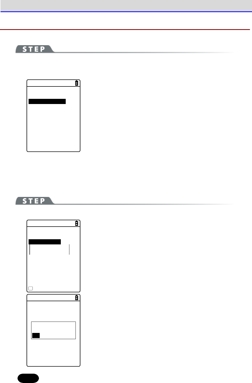
Chapter 4 System Menu 4-9 Device: Setting Hardware Functions
GTX-221-G User’s Manual
169
4-9-3 Bluetooth: Registering and Setting the Bluetooth Device
[System Menu]→[7: Device]→[3: Bluetooth]
Select the setting target device.
< Bluetooth >
1:Local device
2:Remote device
・Local device: Set the Handy Terminal.
・Remote device: Set a device to connect to the Handy Terminal.
■Local Device
Display the BD address of the Handy Terminal.
[System Menu]→[7: Device]→[3: Bluetooth]→[1: Local device]
< Prooerty >
1:Device name
XIT-220
2:BD Address
[00:00:00:00:00:00]
3:Security
4:Version
Save
F1
Set the following:
・Device name
・Security
"BD Address" is fixed; you cannot change its details.
Would you like to
save settings?
YES NO
The details set for each item will not be saved automatically. To
save the setting details, press the【F1】key or the【C】key on this
screen and select [Yes] on a confirmation dialog box.
Hint
Only when Local device is currently set, a search from a remote device is allowed.
Otherwise, no search will be allowed.
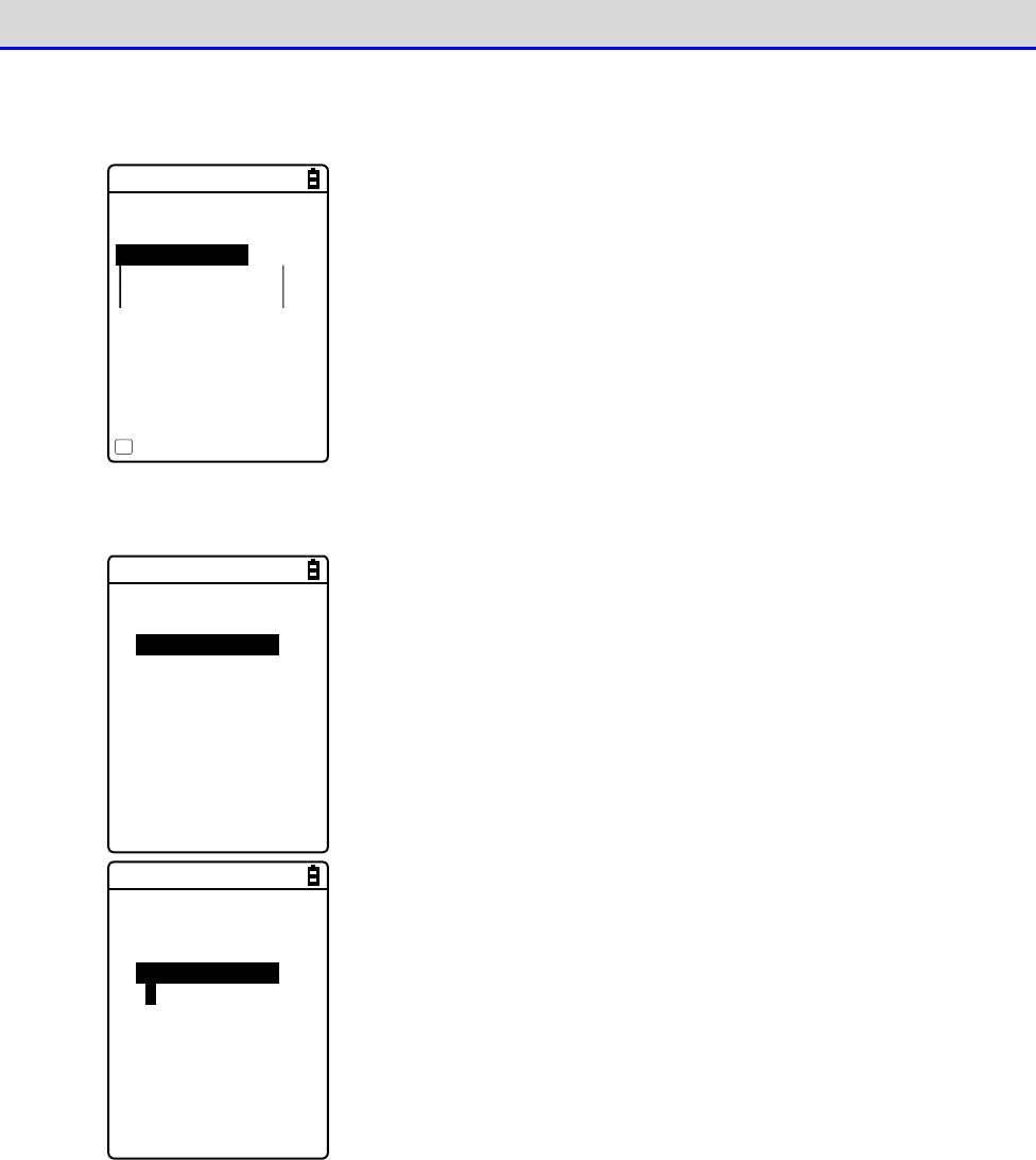
Chapter 4 System Menu 4-9 Device: Setting Hardware Functions
GTX-221-G User’s Manual
170
①Select [Device name],
< Prooerty >
1:Device name
XIT-220
2:BD Address
[00:00:00:00:00:00]
3:Security
4:Version
Save
F1
Enter the name of the Bluetooth device.
The device name should be a value up to 30 alphanumeric and symbol
characters and case-sensitive.
②Select [Security].
< Security >
Pairing Enable
PIN code
[ ]
Make settings related to authentication for connection.
When this checkbox is marked, perform authentication when a
connection request is made to the local device from a remote de
vice.
Only authenticated remote devices are permitted to connect to the
local device.
< Security >
Pairing Enable
PIN code
[ ]
Set the PIN code.
The PIN (Personal Identification Number) code is a password used
for authentication.
You can enter a value up to 16 characters using uppercase and
lowercase alphabet, numeric, and symbol characters.
The entered PIN code is displayed hidden beneath the asterisks (*).
Chapter 4 System Menu 4-9 Device: Setting Hardware Functions
GTX-221-G User’s Manual
171
③Select [Version].
< Version >
hci : 2.0
hr : 0x0m5m
Imp : 2.0
man : csr
Is : 0x0m5m
Check the version of the built-in Bluetooth device's firmware.
■Remote Device
Make settings related to devices (remote devices) to connect to the Handy Terminal.
[System Menu]→[7: Device]→[3: Bluetooth]→[2: Remote device]
< Remote device >
1:Device list
2:Search for devices
3:Search option
・Device list: Register remote device information.
・Search for devices: Search for remote devices around the
Handy
Terminal.
・Search option: Set the number of devices to search for through
Search for devices.
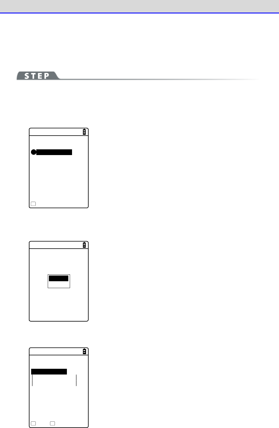
Chapter 4 System Menu 4-9 Device: Setting Hardware Functions
GTX-221-G User’s Manual
172
●Device list
For information about remote devices to connect to, you can register a maximum of seven entries.
When such information has been registered in advance, you do not have to set device information
for each connection.
[System Menu]→[7: Device]→[3: Bluetooth]→[2: Remote device]
→[1: Device list]
①
Select an item number to make registration.
< Device list >
1:(No Device)
2:(No Device)
3:(No Device)
4:(No Device)
5:(No Device)
6:(No Device)
7:(No Device)
Menu
F1
Select an item number and set device information to it in s
equence.
When device information has already been registered, a device name
is displayed to the right of an item number. If nothing is reg-
istered, "(No Device)" is displayed to the right of an item number.
(Note that device information is recognized as already registered
when the entered device name is equal to or longer than one character
and the entered BD address is any value other than
"00:00:00:00:00:00").
A device with a checkmark displayed to the left of its item number
is the default device. In the System Menu, to use Bluetooth
communication, connect to the default device.
Default
Erase
Press the【F1】key to display the submenu.
Set the following as needed:
・Default
Set the registered device being selected, as the default device.
・Erase
Erase the registered device information.
②
Select the item to set.
< Prooerty >
1:Device name
XIT-220
2:BD Address
[00:03:7A:0B:0A:AB]
3:Security
Save Search
F1 F2
Set the following items, press the【F1】key, and select [Yes] to
save the settings.
・Device name
・BD Address
・Security
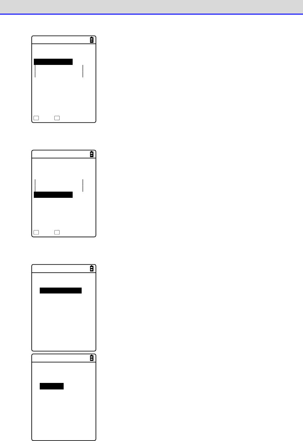
Chapter 4 System Menu 4-9 Device: Setting Hardware Functions
GTX-221-G User’s Manual
173
③
Select [Device name].
< Prooerty >
1:Device name
XIT-220
2:BD Address
[00:03:7A:0B:0A:AB]
3:Security
4:Version
Save Search
F1 F2
Enter the name of the Bluetooth device.
Set this item, press the【F1】key, and select [Yes] to save the
settings.
The device name should be a value up to 30 alphanumeric and symbol
characters and case-sensitive.
④
Select [BD Address].
< Prooerty >
1:Device name
XIT-220
2:BD Address
[00:03:7A:0B:0A:AB]
3:Security
4:Version
Save Search
F1 F2
Enter the BD address.
Set this item, press the【F1】key, and select [Yes] to save the
settings.
The BD address is an hardware address unique to a device.
It is a fixed 12 hexadecimal-digit number (0-9, A-F).
⑤
Select [Security].
< Security >
Pairing Enable
PIN code
[ ]
Set the authentication for connection.
When this checkbox is marked, perform authentication when a
connection request is made to the local device from a remote de
vice.
Only authenticated remote devices are permitted to connect to the
local device.
< Security >
Pairing Enable
PIN code
[******** ]
Set the PIN code.
The PIN(Personal Identification Number) code is a password used for
authentication.
You can enter a value up to 16 characters using uppercase and
lowercase alphabet, numeric, and symbol characters.
For security, the entered PIN code is displayed after being
converted into asterisks (*).
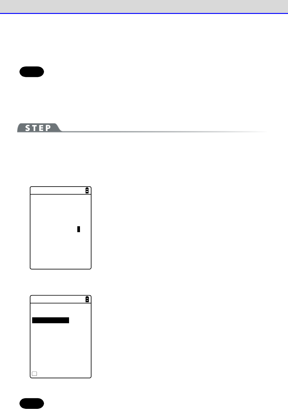
Chapter 4 System Menu 4-9 Device: Setting Hardware Functions
GTX-221-G User’s Manual
174
●Search for devices
Search for remote devices around the Handy Terminal. You can set detected remote devices as
registered devices.
Hint
If you want to include other terminals as targets of Search for devices, you need
to keep target devices as "Local device currently set".
"Local device currently set" indicates the status of the <Property> screen in the
local device settings.
[System Menu]→[7: Device]→[3: Bluetooth]→[2: Remote device]
→[2: Search for devices]
①A search starts.
<Search for devices>
Searching ...
Press the【C】key to cancel the search.
②Search results are displayed in list form.
< Search results >
USB-Adaptor
Label-Printer
Property
F1
The names of detected remote devices are displayed in list form.
Hint
Device names in alphanumeric and symbol characters can be detected. Do not use
kana or kanji characters for device names.
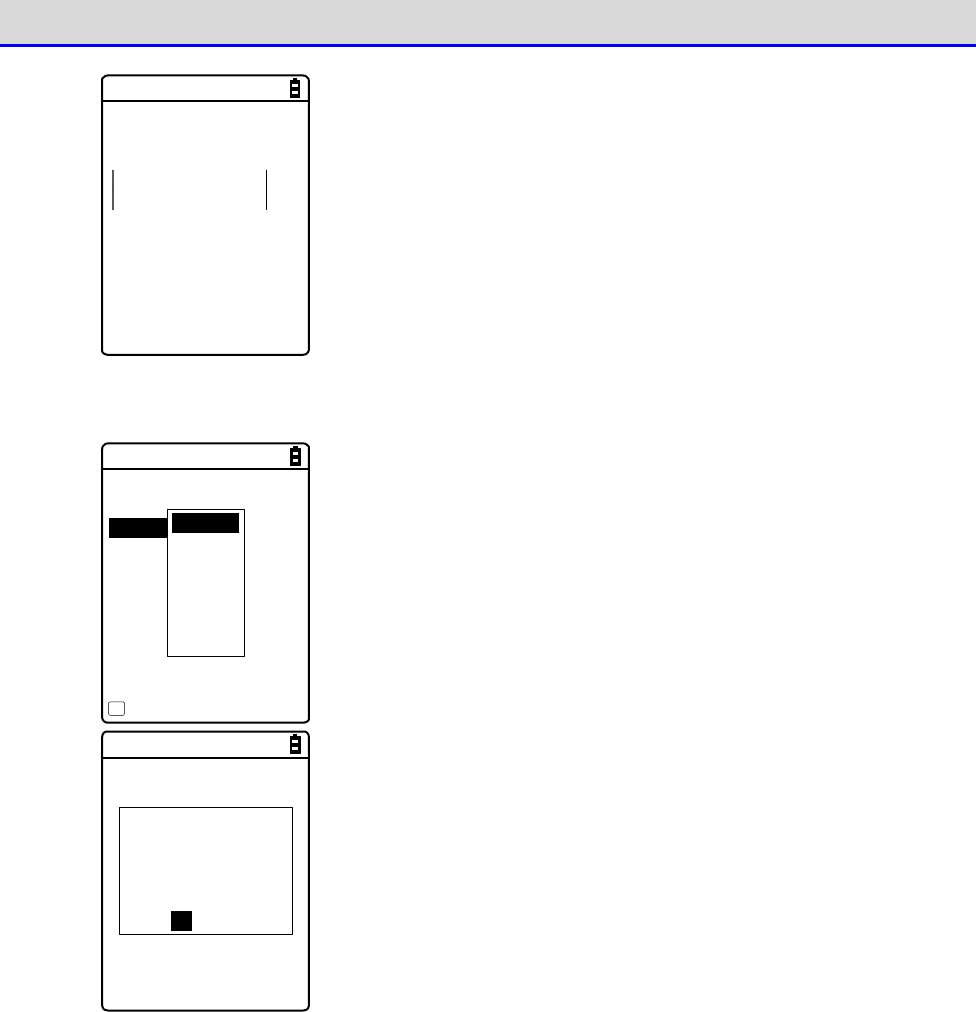
Chapter 4 System Menu 4-9 Device: Setting Hardware Functions
GTX-221-G User’s Manual
175
< Property >
Device name
USB-Adaptor
BD Address
[00:00:00:00:00:00]
Press the【F1】key to display the device name and BD address of the
remote device being selected.
Press the【C】key to return to the <Search results> screen.
③Register the detected remote device.
< Search results >
USB-Adaptor
Label-Printer
Property
F1
Remote1
Remote2
Remote3
Remote4
Remote5
Remote6
Remote7
Select the remote device to register and press the【ENT】key to
display the submenu.
Select the remote number to register the remote device to, and the
device will be registered.
The remote has
been already
registered.
Would you like to
overwrite it?
YES NO
If you select the already registered remote device number, a
confirmation dialog box for overwriting appears.
Select [Yes] or [No].
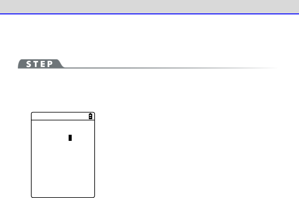
Chapter 4 System Menu 4-9 Device: Setting Hardware Functions
GTX-221-G User’s Manual
176
●Search option
Set the maximum number of remote devices to be detected through Search for devices.
[System Menu]→[7: Device]→[3: Bluetooth]→[2: Remote device]
→[3: Search option]
< Search option >
Search MAX [9] (1-9)
Specify the number of devices to search for.
You can set a value in the range 1-9 for the number of devices.
The greater the number of devices to search for, the longer the
search duration becomes.
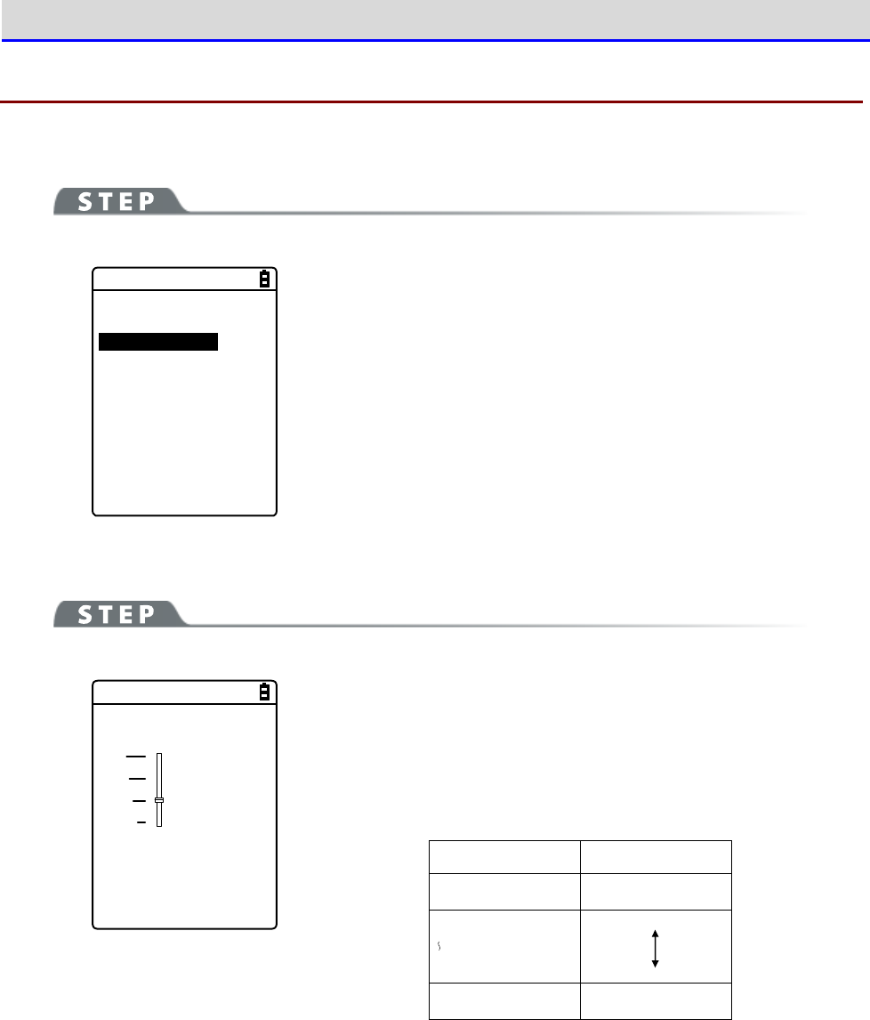
Chapter 4 System Menu 4-9 Device: Setting Hardware Functions
GTX-221-G User’s Manual
177
4-9-4 Setting the Display/Backlight Luminosity
Set luminosity:
[System Menu]→[7: Device]→[4: Display]
< Display >
1:Luminosity
2:SetAlsSensor
Make a selection from the following items:
・Luminosity: Adjust the backlight luminosity.
・SetAlsSensor: Set automatic backlight dimming.
■Luminosity
[System Menu]→[7: Device]→[4: Display]→[1: Luminosity]
< Luminosity >
F6(High)
Level : 2
F7(Low)
【▲】key is used to move the slider up and the【
▼
】key is used
to move the slider down to adjust luminosity..
You can set luminosity in four steps; move the slider and luminosity
changes in real-time.
Level
Luminosity
High Bright
Low Dark
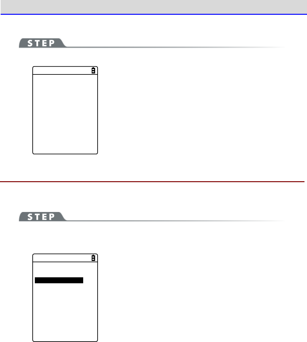
Chapter 4 System Menu 4-9 Device: Setting Hardware Functions
GTX-221-G User’s Manual
178
■Light Sensor
[System Menu]→[7: Device]→[4: Display]→[2: Light Sensor]
< Light Sensor >
Enabled
Enable Ambient Light Sensor.
When Ambient Light Sensor is enabled, the luminosity setting will
be disabled.
4-9-5 Tone/Vibrator: Setting the Volume, LED, and the Vibrator
Use this category to set the volume, LED, and vibrator.
[System Menu]→[7: Device]→[5: Tone/Vibrator]
Select the device to set.
< Tone/Vibrator >
1:Volume
2:Indicator func
3:Click Sound
Make a selection from the following items:
・Volume
・Indicator func
・Click Sound
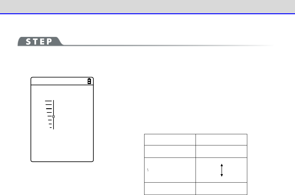
Chapter 4 System Menu 4-9 Device: Setting Hardware Functions
GTX-221-G User’s Manual
179
■Volume
[System Menu]→[7: Device]→[5: Tone/Vibrator]→[Volume]
Adjust the volume of the buzzer sound.
< Volume >
F6(Up)
Level : 4
F7(Down)
You can adjust the volume in eight steps from level 1 to 8.
【
】key moves the slider up and the【
】
key moves the slider down.
As the slider moves up and down, the volume changes in real-time;
you can check the current level on the spot.
The relationship between the level and the volume is as follows:
Level
Volume
8 Bigger
1 Smaller
When 1 is set, the buzzer sound is silenced.
■Indicator Func
Indicator func is a generic term indicating a combination of three devices alerting the operator
(buzzer/vibrator/LED).
Using Indicator func, the current situation can better appeal to the senses of the operator.
Set which indicator should be used in what situation to suit each application.
Three patterns are available for each of the following six scenes: five typical scenes of
operation such as pressing (clicking) a key and entering data, and one arbitrary scene that
can be set by the customer (user).
Note that the indicators for pattern 3 of each scene apply to the system menu.
For example,
•
When data is entered, generate one short high tone and light the green LED ON
•
When an error occurs, generates three low tones while operating the vibrator and blink
the red LED
As shown in this example, various settings can be made to suit the customer's use environment.
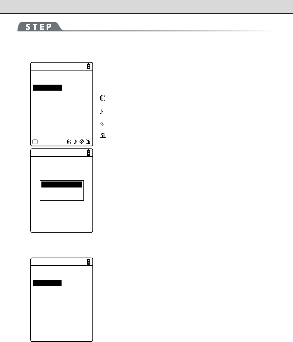
Chapter 4 System Menu 4-9 Device: Setting Hardware Functions
GTX-221-G User’s Manual
180
[System Menu]→[7: Device]→[5: Tone/Vibrator]→[2: Indicator func]
①
Select the indicator to set.
< Indicator func >
1:Cancel-1
2:Cancel-2
3:Cancel-3
4:Enter-1
5:Enter-2
6:Enter-3
7:Click-1
8:Click-2
9:Click-3
Menu
F1
Icons indicating the current indicator settings are displayed in
the bottom right of the screen.
: Buzzer enabled.
: Audio enabled.
: Vibrator enabled.
: LED enabled.
Preview
Initialize
Initialize all
Press the【F1】key to display the submenu.
・Preview
You can actually feel the current indicator settings.
・Initialize
Discard the settings for the selected pattern and restore the
initial settings.
・Initialize all
Discard the settings for all the patterns for all the scenes and
restore the initial settings.
②
Select the device to set.
< Device >
1:Buzzer
2:Audio
3:Vibrator
4:LED
After selecting the item to set on the screen in step
①
, and press
the【ENT】key to display the device name.
Select the device to set and press the【ENT】key.
Set the operating conditions for each device by referring to the
next section.
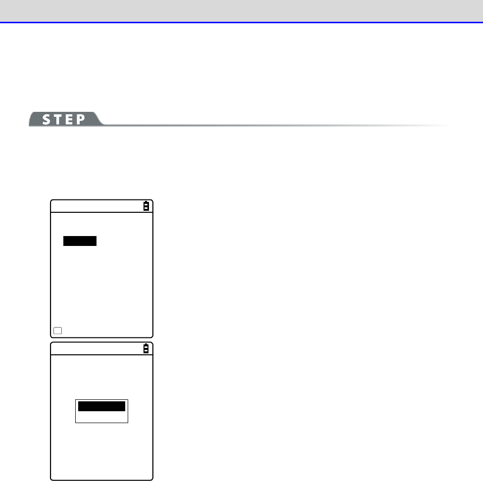
Chapter 4 System Menu 4-9 Device: Setting Hardware Functions
GTX-221-G User’s Manual
181
●Device operating conditions setting
There are operating conditions common to all devices and operating conditions specific to each
device.
[System Menu]→[7: Device]→[5: Tone/Vibrator]→[2: Indicator func]
→ Select the device.
Operation common to all devices
< Buzzer >
Enabled
Freq. [0580]Hz
ON [00040]ms
OFF [00000]ms
Repeat[00]
Menu
F1
Turn ON/OFF the relevant device operation using the check box for
it.
Mark the check box to enable the relevant device operation, and
unmark it to disable it regardless of other settings.
This setting is displayed as an icon.
Preview
Initialize
Press the【F1】key to display the submenu.
Set as needed.
・Preview
You can actually feel the current indicator settings.
・Initialize
Discard the settings for the pattern currently set and restore
the initial settings.
Note that when【F1】is displayed in the bottom left of the screen,
the operation procedure is the same for all device operation
conditions.
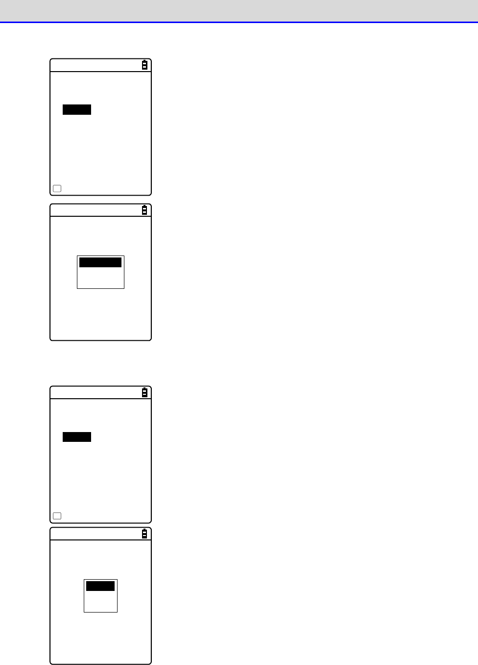
Chapter 4 System Menu 4-9 Device: Setting Hardware Functions
GTX-221-G User’s Manual
182
Set the buzzer frequency ([1: Buzzer]).
< Buzzer >
Enabled
Freq. [0580]Hz
ON [00040]ms
OFF [00000]ms
Repeat[00]
Menu
F1
Move the cursor over[Freq.]and press the【ENT】key.
The cursor moves to the frequency value.
The setting range is 245-9000Hz. You can set the frequency in units
of 1Hz within this frequency range. Due to the characteristics of
the speaker, we recommend using the buzzer at a frequency in the
range 500-3000Hz.
Low tone
Mediant
High tone
While entering the frequency, the content in the function key
guidance in the lower left of the screen changes.
Press the【F1】key to display the frequency sample submenu.
You can smoothly set the frequency by fine-adjusting the value based
on the sample.
Set the LED color ([4:LED]).
< LED >
Enabled
Color [Red ]
ON [00500]ms
OFF [00000]ms
Repeat[00]
Menu
F1
Move the cursor over [Color] and press the【ENT】key.
Red
Green
Orange
Select a color from the submenu.
Chapter 4 System Menu 4-9 Device: Setting Hardware Functions
GTX-221-G User’s Manual
183
■Click Sound
Set whether to generate a click sound when a key is pressed.
A click sound plays immediately when a key is pressed. For that reason, the sound of an application
program or of an indicator can be interrupted by a click sound. Depending on the timing, the
sound may become unclear due to such an interruption.
[System Menu]→[7: Device]→[5: Tone/Vibrator]→[3: Click Sound]
Select a pattern for the sound to play when a key is pressed.
< Click Sound >
None
Beep
Beep + Audio
Audio
・None (Default)
Do not generate a click sound.
・Beep
For every key, generate a short beep sound when a key is pressed.
・Beep + Audio
Read a number when a numeric key is pressed. Generate a beep sound
when any other key is pressed.
・Audio
Read a number only when a numeric key is pressed. Do not generate
any sound when any other key is pressed.
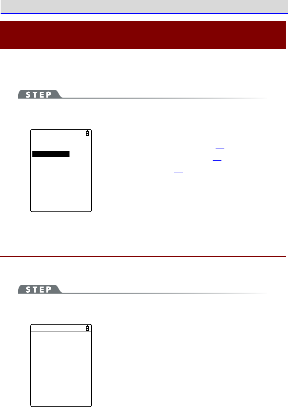
Chapter 4 System Menu 4-10 Management: Setting Basic Information and Management
GTX-221-G User’s Manual
184
4-10 Management: Setting Basic Information and
Management
Use this category to check basic information of, improve the performance of, and perform
maintenance of the Handy Terminal.
[System Menu]→[8: Manage]
Select the item to manage.
< Management >
1:System info
2:Format
3:Clone
4:Drive
5:Mothball
6:Wizard
7:OS Update
Select the item to set.
・System info: Check the OS version (P.184).
・Format: Format the registry/drive (P.185).
・Clone: Create a copy (P.187).
・Drive: Display the drive information (P.195).
・Mothball: Settings when not using the product for long (P.196)
.
・ Wizard: Start up the screen facilitating configuration of
communication settings (P.197).
・OS Update: Update the OS of the Handy Terminal (P198.)
4-10-1 System info: Checking the OS Version
Display the version information of the installed OS.
[System Menu]→[8: Manage]→[1: System info]
Check the OS version.
< System info >
O S : 01.03.04
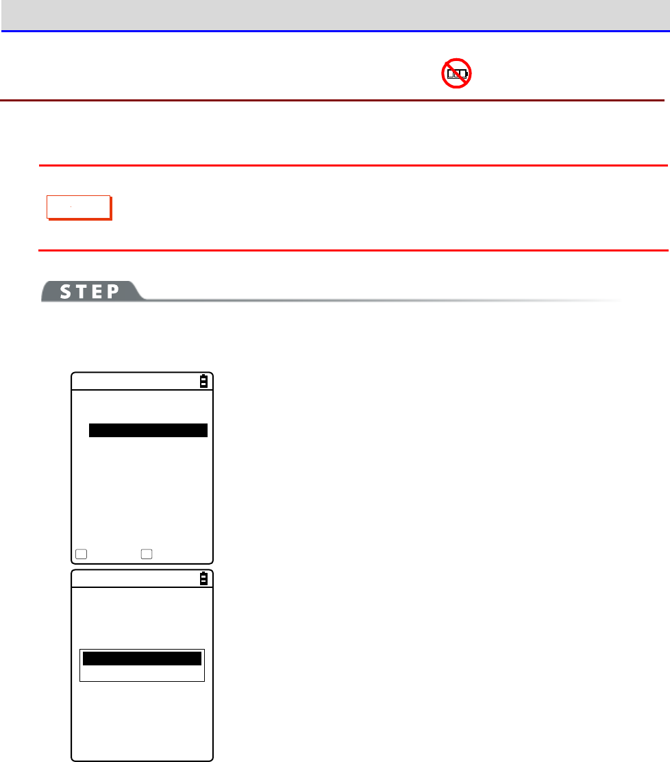
Chapter 4 System Menu 4-10 Management: Setting Basic Information and Management
GTX-221-G User’s Manual
185
4-10-2 Format: Registry/Drive Formatting
Format the registry or drives.
C
a
u
t
i
o
n
When formatting is performed, the factory default settings will be restored and
all the files will be deleted. When formatting, with the above in mind, be very
careful.
[System Menu]→[8: Manage]→[2: Format]
①
Select the item to format.
< Format >
RegistryInitialize
FDrive
SDrive
RDrive(microSD)
Execute Menu
F1 F2
Mark the checkbox for the item to format.
If none of the checkboxes is marked, you cannot perform format
ting.
All checks applied
All checks removed
Press the【F2】key to display the submenu.
・All checks applied
Mark all the checkboxes.
・All checks removed
Unmark all the checkboxes.
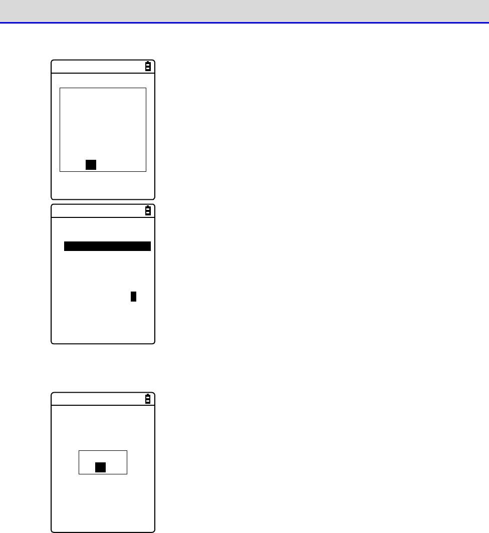
Chapter 4 System Menu 4-10 Management: Setting Basic Information and Management
GTX-221-G User’s Manual
186
②
Start formatting.
If Format was
executed,
all settings and
all files would
be deleted.
Would you like to
execute Format?
YES NO
Press the【F1】key, and an execution confirmation dialog box appears.
Select [Yes] or [No].
< Format >
RegistryInitialize
FDrive
SDrive
RDrive(microSD)
Formatting ...
The items with their checkboxes marked will be formatted in
sequence.
③
Finish formatting.
Completed
OK
Press the【ENT】key to finish formatting.
If the registry is initialized, the power will be turned OFF.
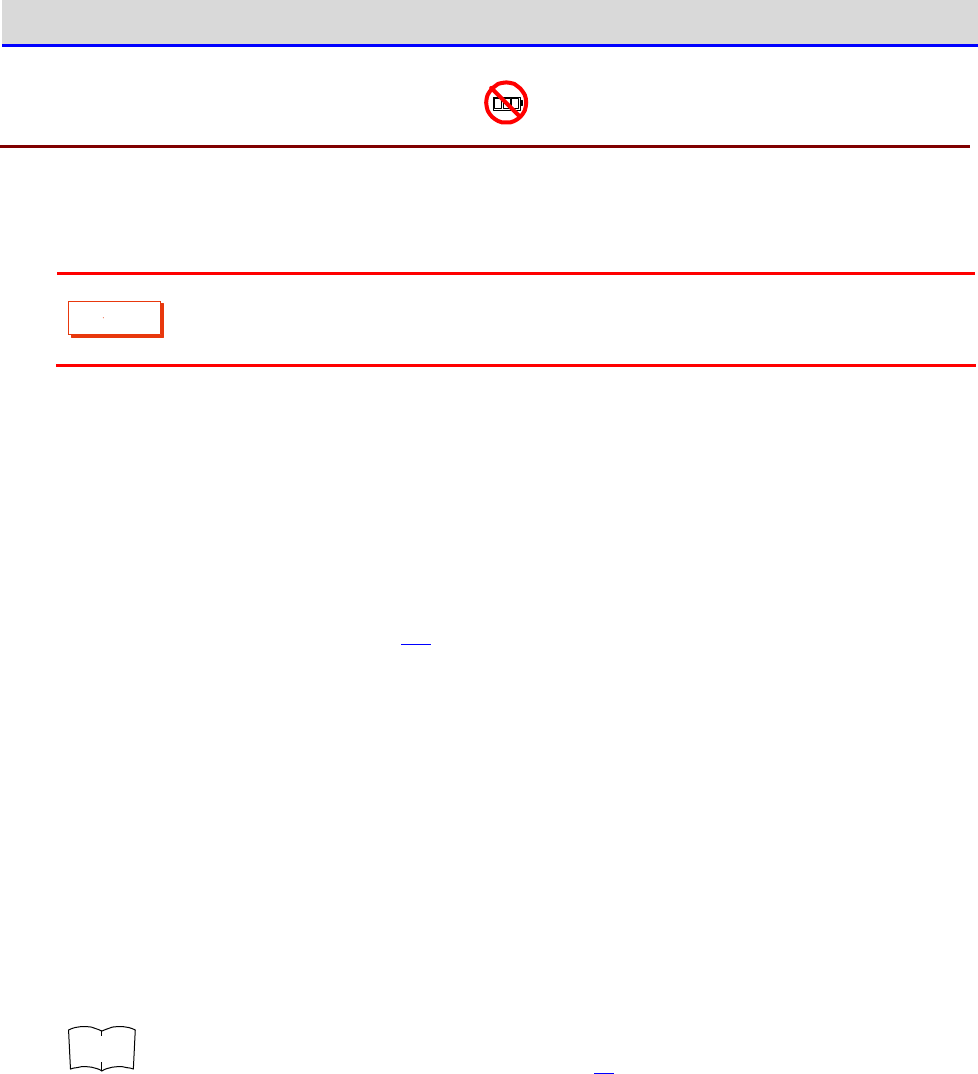
Chapter 4 System Menu 4-10 Management: Setting Basic Information and Management
GTX-221-G User’s Manual
187
4-10-3 Clone: Creating a Copy
Copy the parameters set on the system menu and files saved in the F drive to another XIT-2xx
to create a terminal with the same settings and files.
C
a
u
t
i
o
n
Files saved in the S drive will not be copied.
■How to Execute Clone
Clone can be executed using either Bluetooth communication or infrared communication (IrDA).
①Pre-setting
<Bluetooth communication>
Register a copy terminal as a remote device of the device to be used as a master terminal.
「Refer to "■Remote Device" (P.171).
<Infrared communication (IrDA)>
No pre-setting required.
②Using the master terminal, select the items to clone (copy).
③Initialize the copy terminal.
④Confirm that the copy terminal becomes ready, and then execute Clone on the master terminal.
⑤Confirm that completion of Clone is displayed on the master terminal.
⑥Close the confirmation dialog box on the copy terminal and turn the power OFF to finish the
operation.
r
rr
re
ee
ef
ff
f
For Bluetooth communication and infrared communication (IrDA), refer to "Chapter
3 Communication Environment Settings (P.66).
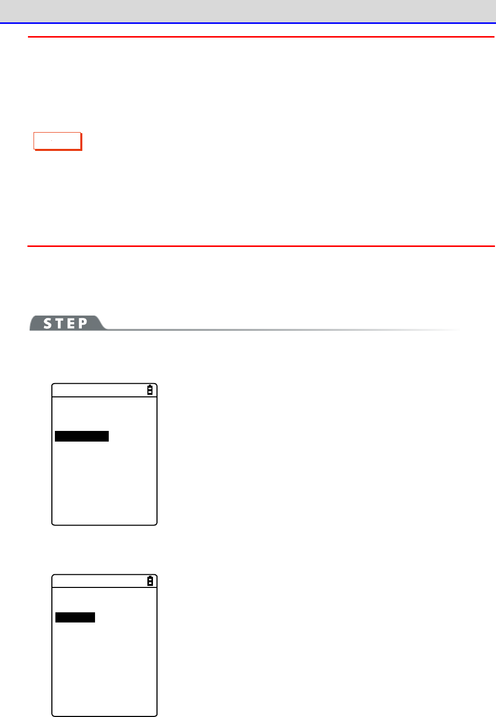
Chapter 4 System Menu 4-10 Management: Setting Basic Information and Management
GTX-221-G User’s Manual
188
C
a
u
t
i
o
n
When executing Clone, thoroughly understand the following and be very careful.
・When the radio condition is bad during Bluetooth communication, or when
the surrounding environment is bad such as light disturbance during infrared
communication not, even if copying cannot be performed correctly, "Completed"
may be displayed on the master side.
・The content inside a copy terminal is initialized before reception from the master
terminal. For that reason, if Clone fails, the factory default settings may be
restored or all the files may be deleted.
・Since a copy terminal is initialized first, it may take time to become ready
to perform Clone on it.
■Bluetooth/IrDA
[System Menu]→[8: Manage]→[3: Clone]
①
Select the communication method.
< Device type >
1:Bluetooth
2:IrDA
3:microSD
Select between Bluetooth or IrDA (infrared).
・Bluetooth
・IrDA
②
Set whether the Handy Terminal is a master terminal or copy terminal.
< Clone >
1:Master
2:Copy
・Master: When the product is a copy source XIT-2xx.
・Copy: When the product is a copy destination XIT-2xx.
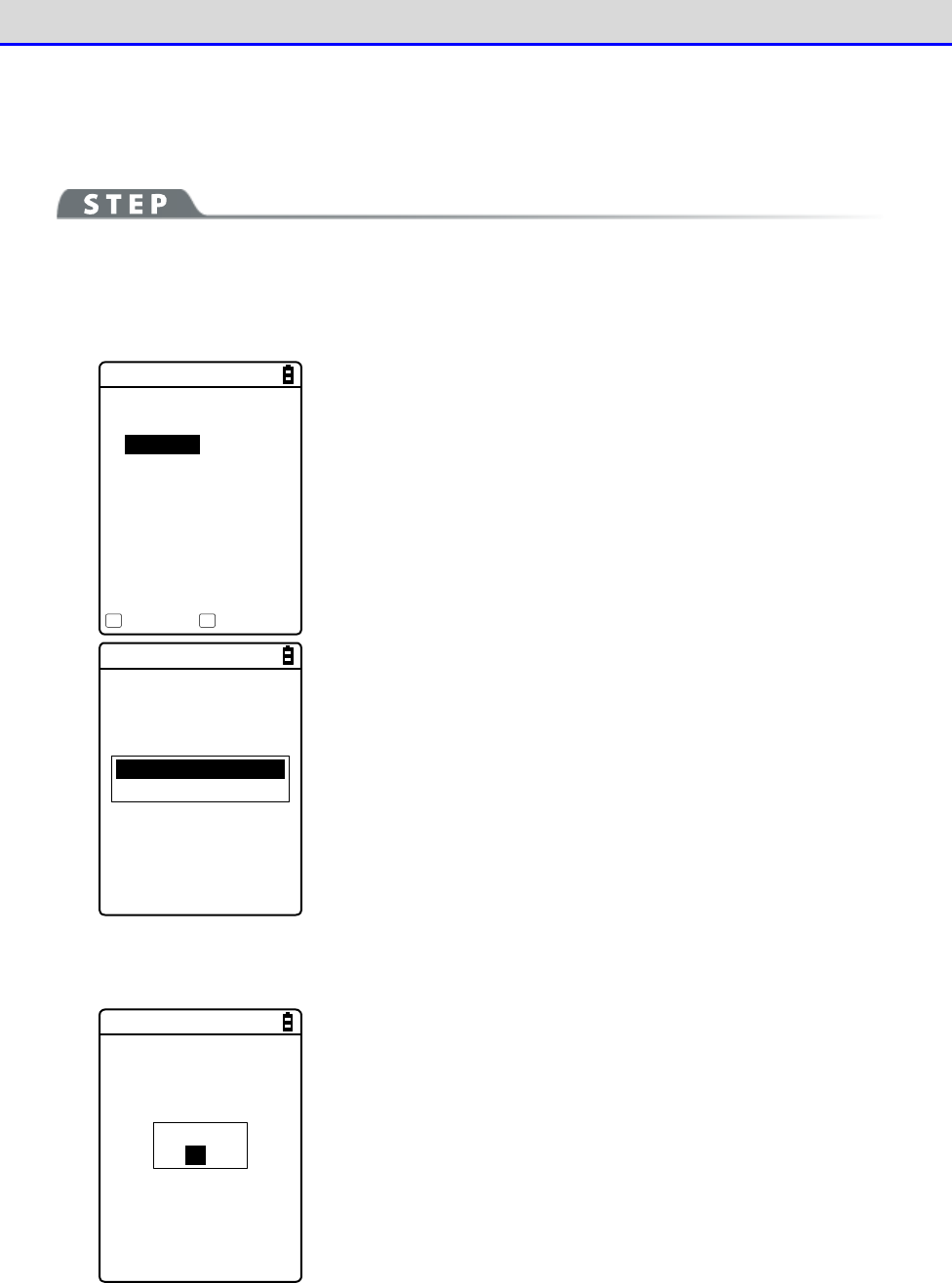
Chapter 4 System Menu 4-10 Management: Setting Basic Information and Management
GTX-221-G User’s Manual
189
●Master: The Handy Terminal is a copy source.
Select the settings and files to copy and execute Clone.
[System Menu]→[8: Device]→[3: Clone]→[1: Bluetooth/2: IrDA]
→[1: Master]
①
Select the items to clone.
< Clone(master) >
System
Security
User
Unique
FDrive
Execute Menu
F1 F2
Select the items to copy.
Confirm that the copy terminal has been completely initialized and
is waiting for connection, press the【F1】key to start executing
Clone.
All checks applied
All checks removed
Press the【F2】key to display the submenu.
Set an item as needed.
・All checks applied
Mark all the checkboxes.
・All checks removed
Unmark all the checkboxes.
②
Finish the Clone operation.
Completed
OK
Press the【ENT】key to finish the Clone operation.

Chapter 4 System Menu 4-10 Management: Setting Basic Information and Management
GTX-221-G User’s Manual
190
●Explanations about items to copy
・System
A parameter managed by the Handy Terminal's system software (OS) independently.
You do not have to select this item because this parameter is not used in user applications.
・Security
A password to start the system menu and security settings for Bluetooth or WLAN.
Select this item if you want to use the same security settings also for the copy terminal.
・User
Parameters set by all the system menu items other than Security and Unique.
If you select this item, most of the parameters set on the system menu will be copied.
・Unique
Terminal ID, Bluetooth local device name, and the local security settings.
Basically, these are parameters unique to each terminal. Select this item if you want to make
a copy including such parameters.
・FDrive
Copy files stored in the F drive.
Select this item if you want to copy application programs or the master file.
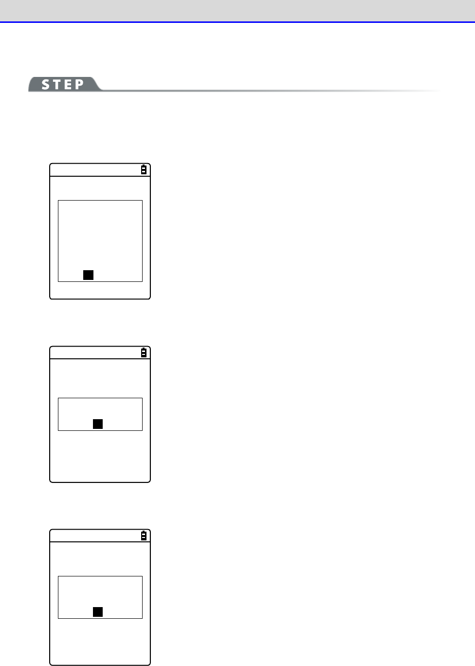
Chapter 4 System Menu 4-10 Management: Setting Basic Information and Management
GTX-221-G User’s Manual
191
●Copy: The Handy Terminal is a copy destination.
[System Menu]→[8: Manage]→[3: Clone]→[1: Bluetooth/2: IrDA]
→[2: Copy]
①
Initialize the Handy Terminal.
< Clone(copy) >
If Clone was
executed,
all settings and
all files would
be deleted.
Would you like to
execute Clone?
YES NO
Execute before executing Clone on the master terminal (pressing the
【F1】key.)
An execution confirmation dialog box appears.
Select [Yes] or [No].
②
You are notified that the Clone is ready to execute.
The Clone is
ready to execute.
OK
Press the【ENT】key to wait for connection.
At this point, execute Clone on the master terminal (press the【F1】
key).
③
Check the screen on the master terminal.
Please check that
the master is
completed.
OK
Completion of Clone cannot be confirmed on the copy terminal. Be
sure to confirm on the screen on the master terminal that the
transfer operation has been completed. If you find on the master
terminal that the transfer operation has not been completed, execute
Clone again.
Press the【ENT】key.
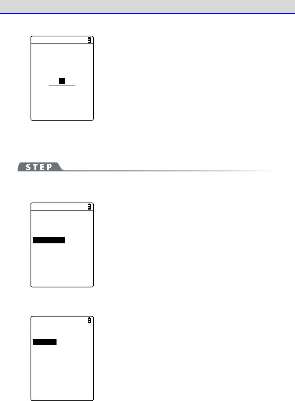
Chapter 4 System Menu 4-10 Management: Setting Basic Information and Management
GTX-221-G User’s Manual
192
④
Finish the Clone operation.
Shutdown
OK
Press the【ENT】key.
The power is turned OFF.
■microSD
[System Menu]→[8: Manage]→[3: Clone]
①
Select the method.
< Device type >
1:Bluetooth
2:IrDA
3:microSD
Select microSD.
②
Specify whether the Handy Terminal is on the export side or on the import side.
< Clone >
1:Export
2:Import
・Export: When the product is a copy source XIT-2xx.
・Import: When the product is a copy destination XIT-2xx.
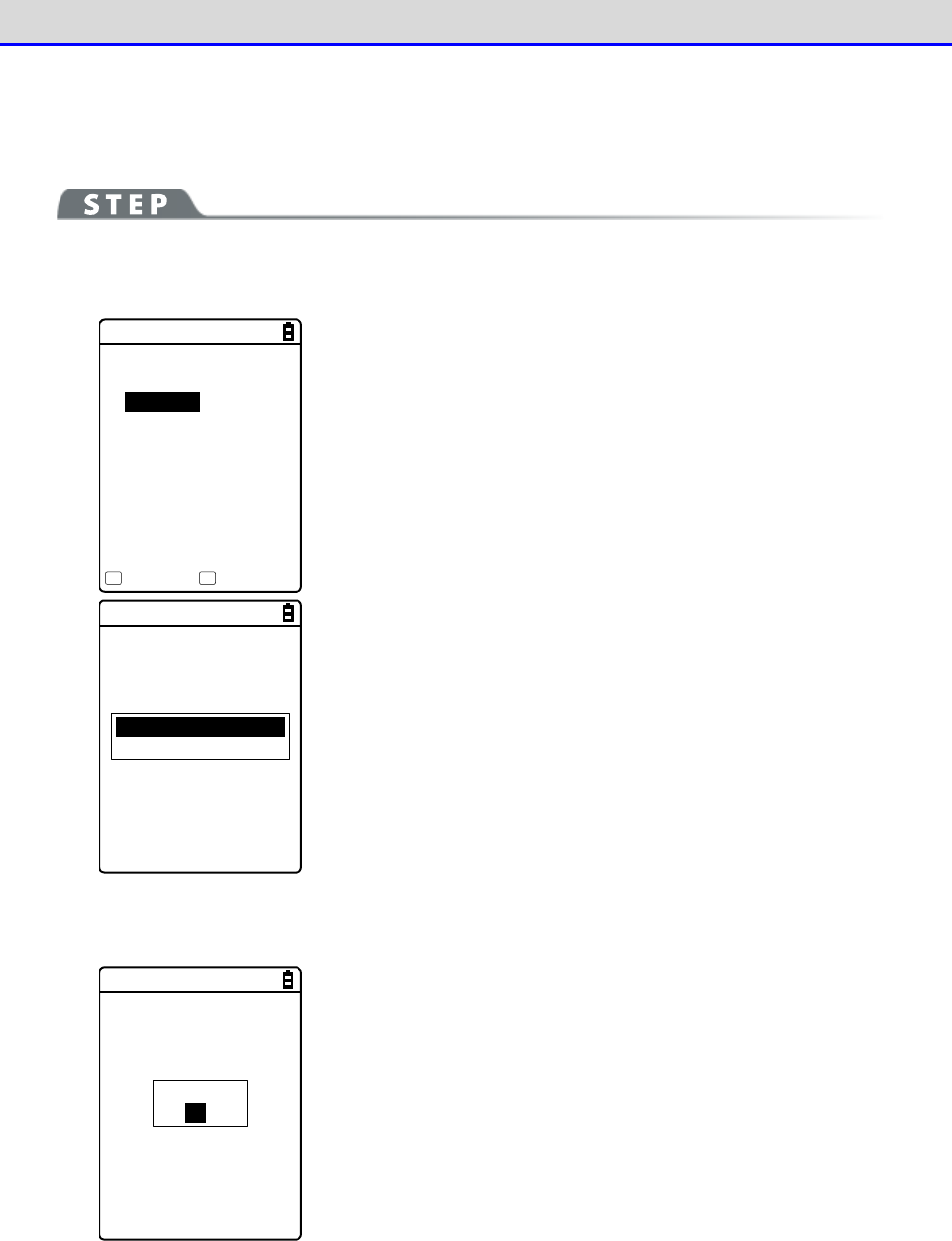
Chapter 4 System Menu 4-10 Management: Setting Basic Information and Management
GTX-221-G User’s Manual
193
●Export: The Handy Terminal is a copy source.
Select the settings and files to copy and execute Clone.
[System Menu]→[8: Manage]→[3: Clone]→[3: microSD]→[1: Export]
①
Select the items to clone.
< Clone(Export) >
System
Security
User
Unique
FDrive
Execute Menu
F1 F2
Select the items to copy.
All checks applied
All checks removed
Press the【F2】key to display the submenu.
Set an item as needed.
・All checks applied
Mark all the checkboxes.
・All checks removed
Unmark all the checkboxes.
②
Finish the Clone operation.
Completed
OK
Press the【ENT】key to finish the Clone operation.
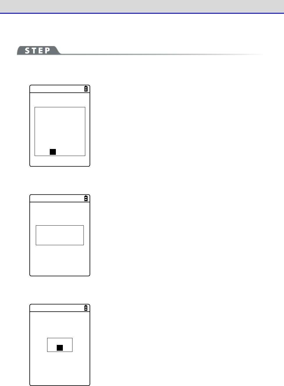
Chapter 4 System Menu 4-10 Management: Setting Basic Information and Management
GTX-221-G User’s Manual
194
●Import: The Handy Terminal is a copy destination.
[System Menu]→[8: Manage]→[3: Clone]→[3: microSD]→[2: Import]
①
Confirm execution.
< Clone(Import) >
If Clone was
executed,
all settings and
all files would
be deleted.
Would you like to
execute Clone?
YES NO
An execution confirmation dialog box appears.
Select [Yes] or [No].
②
Clone will be executed.
Please do not
remove a battery
by any means!
Do not turn the power OFF during execution.
③
Finish the Clone operation.
Shutdown
OK
Press the【ENT】key.
The power is turned OFF.
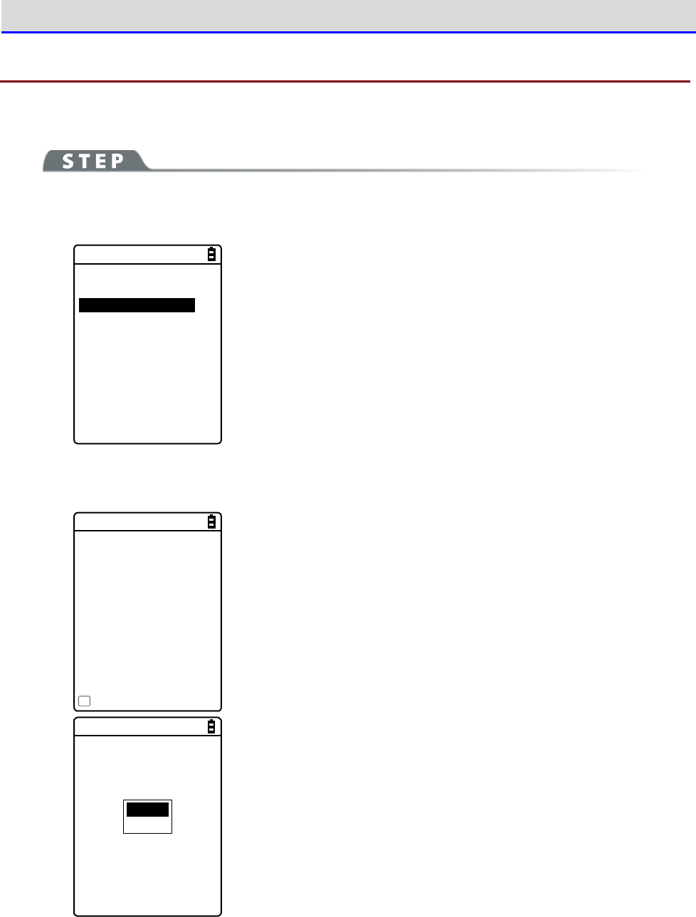
Chapter 4 System Menu 4-10 Management: Setting Basic Information and Management
GTX-221-G User’s Manual
195
4-10-4 Drive: Displaying Drive Information
Use this item to check information about drives and perform their maintenance.
[System Menu]→[8: Manage]→[4: Drive]
①
Select the drive.
< Drive selection >
1:FDrive
2:SDrive
3:RDrive(microSD)
Select the drive and press the【ENT】key.
②
The drive property is displayed.
< FDrive Property >
Capacity
[20578304]Bytes
Used space
[ 205393]Bytes
Free space
[20372911]Bytes
Files
[ 4 / 128]
Defrag
F1
The following information will be displayed:
・Capacity
・Used space
・Free space
・Files
Normal
Deep
For the F drive, press the【F1】key to optimize it by defragmen
tation.
Press the【F1】key, and a dialog box appears.
・Normal
Physically eliminate unneeded regions created while files are
written to or deleted.
・Deep
In addition to defragmentation in Normal mode, reorganize the
secured free regions so that they become contiguous.
It may take several seconds to several minutes to complete
defragmentation in Deep mode depending on the drive's condition.
Normally, we recommend executing defragmentation in Normal mode.
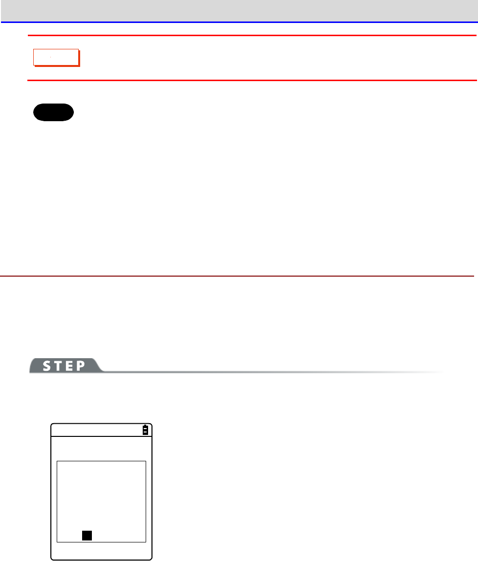
Chapter 4 System Menu 4-10 Management: Setting Basic Information and Management
GTX-221-G User’s Manual
196
C
a
u
t
i
o
n
Never remove the battery pack during defragmentation. If the battery or the battery
pack is removed during defragmentation, files or system programs may be destroyed.
Hint
If files are repeatedly written to or deleted on the F drive, the free space is
gradually fragmented, and eventually, it may become impossible to store large
files or it may take long to start up.
To prevent the F drive from fragmentation, be careful about the following:
・Write data collectively as contiguous data as much as possible.
・When finishing operation, delete the data temporarily stored on the F drive.
・For data that needs to be temporarily stored, try to write it to the S drive.
4-10-5 Mothball: Settings When Not Using the Product For Long
When not using the Handy Terminal for a long period of time, configure settings to suppress
battery consumption.
Execute Resume and erase the S drive.
[System Menu]→[8: Manage]→[5: Mothball]
①
Resume is executed and the S drive is erased.
< Mothball >
The contents of
resume and the
Sdrive are deleted
instead of
suppressing
consumption of a
backup battery.
YES NO
An execution confirmation dialog box appears.
Select [Yes] or [No].
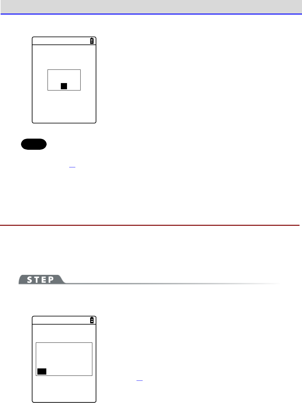
Chapter 4 System Menu 4-10 Management: Setting Basic Information and Management
GTX-221-G User’s Manual
197
②
Finish Mothball preparation.
Completed.
Shutdown.
OK
Press the【ENT】key.
The power is turned OFF.
Hint
When the power is turned ON after Mothball, the message "The SDrive has been
initialized." appears, but it is not a defect (refer to"1-2-7 Long-term Storage"
(P.52)).
4-10-6 Wizard: Starting the Screen Facilitating Configuration
of Communication Settings
Use this item to start again the setting wizard executed when the Handy Terminal was started
for the first time. You can configure the settings minimally required for communication between
the Handy Terminal and a PC.
[System Menu]→[8: Manage]→[6: Wizard]
Configure settings using Wizard.
< Wizard >
Start wizard?
Communication set-
ting can be done
with guidance
YES NO
Select [Yes] or [No].
Select [Yes] to execute the wizard to set WLAN communication. Select
[No] to return to the previous screen.
For details, refer to "■WLAN Communication Settings by Setting
Wizard" (P.70).
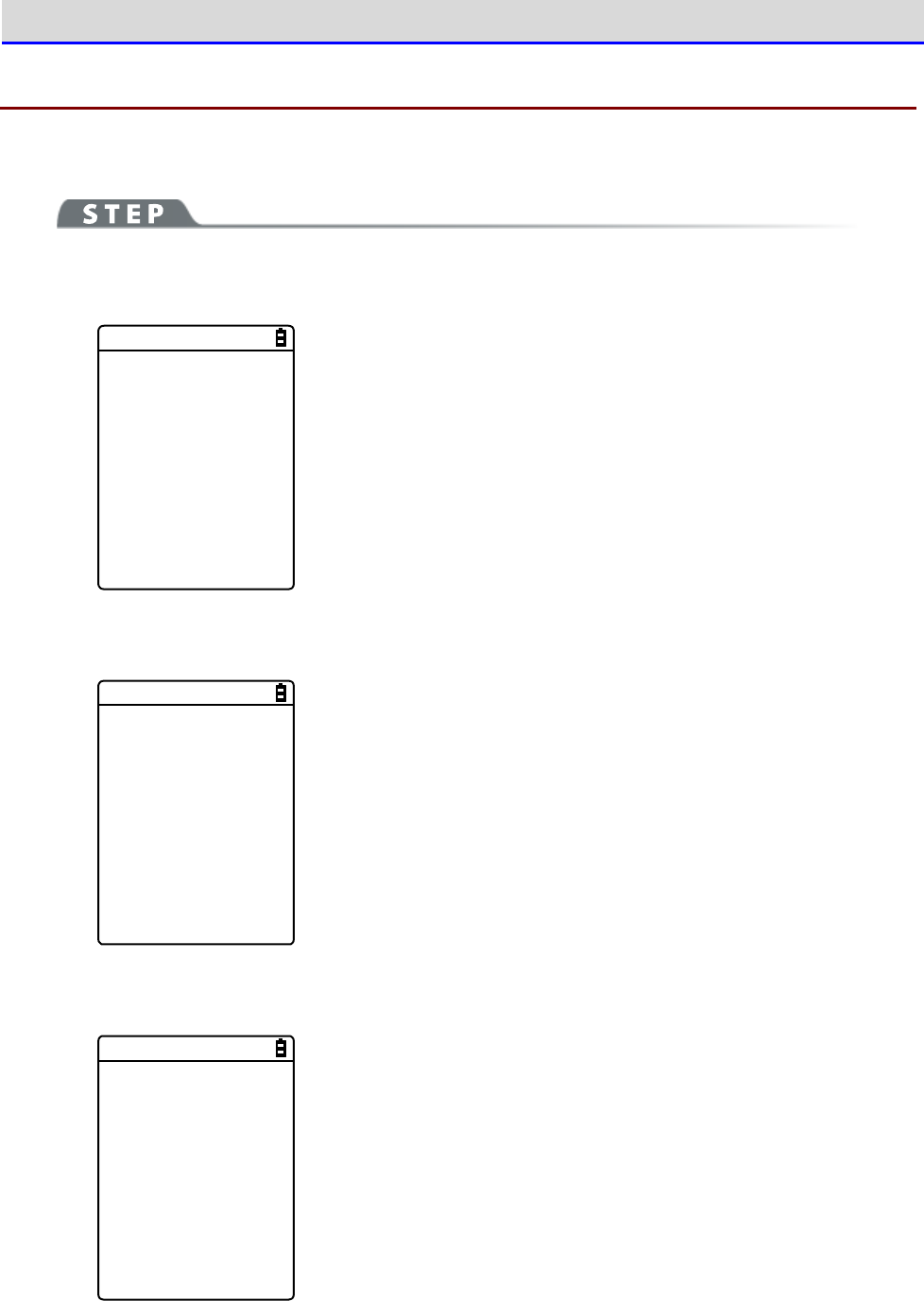
Chapter 4 System Menu 4-10 Management: Setting Basic Information and Management
GTX-221-G User’s Manual
198
4-10-7 OS Update: Updating the OS of TheHandy Terminal
Update the OS of the Handy Terminal.
[System Menu]→[8: Manage]→[7: OS Update]
①
Start updating the OS.
< OS Version UP >
XIT2XX-OS v01.00.00
Mon 01 2012
00:00:00
Updating to
this OS starts.
F1:OK F2:CAN
Press the【F1】key to start updating the OS.
Press the【F2】key to stop updating the OS.
② The Handy Terminal restarts and the OS update process starts.
< OS Update >
OS installation
is in progress.
Please wait ...
Never remove the battery back during OS update.
And, do not press any key.
③ Restart the product.
OS update has
been completed.
Hit any key
to start new OS.
After the OS update has been completed, press any key.
This turns the power OFF.
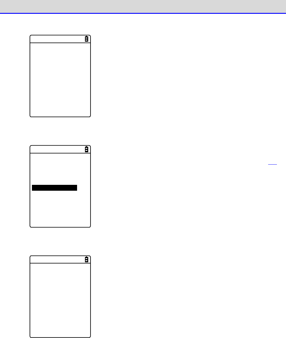
Chapter 4 System Menu 4-10 Management: Setting Basic Information and Management
GTX-221-G User’s Manual
199
④
Turn the power ON (OS starting).
< OS starting >
Please hit ENT key.
Press the【ENT】key.
⑤
Set the time.
< Time >
2012/01/01(Sun)
00/00/00
1:Manual setting
2:Server setting
Set the time and press【C】key.
For how to set the time, refer to "4-3-2 Clock: Set the Time" (P.104).
⑥
Defragmentation will be executed.
< Defrag >
Please wait.
Defragmentation will be executed and then the power will be turned
OFF.
Then, the OS update procedure will become complete.
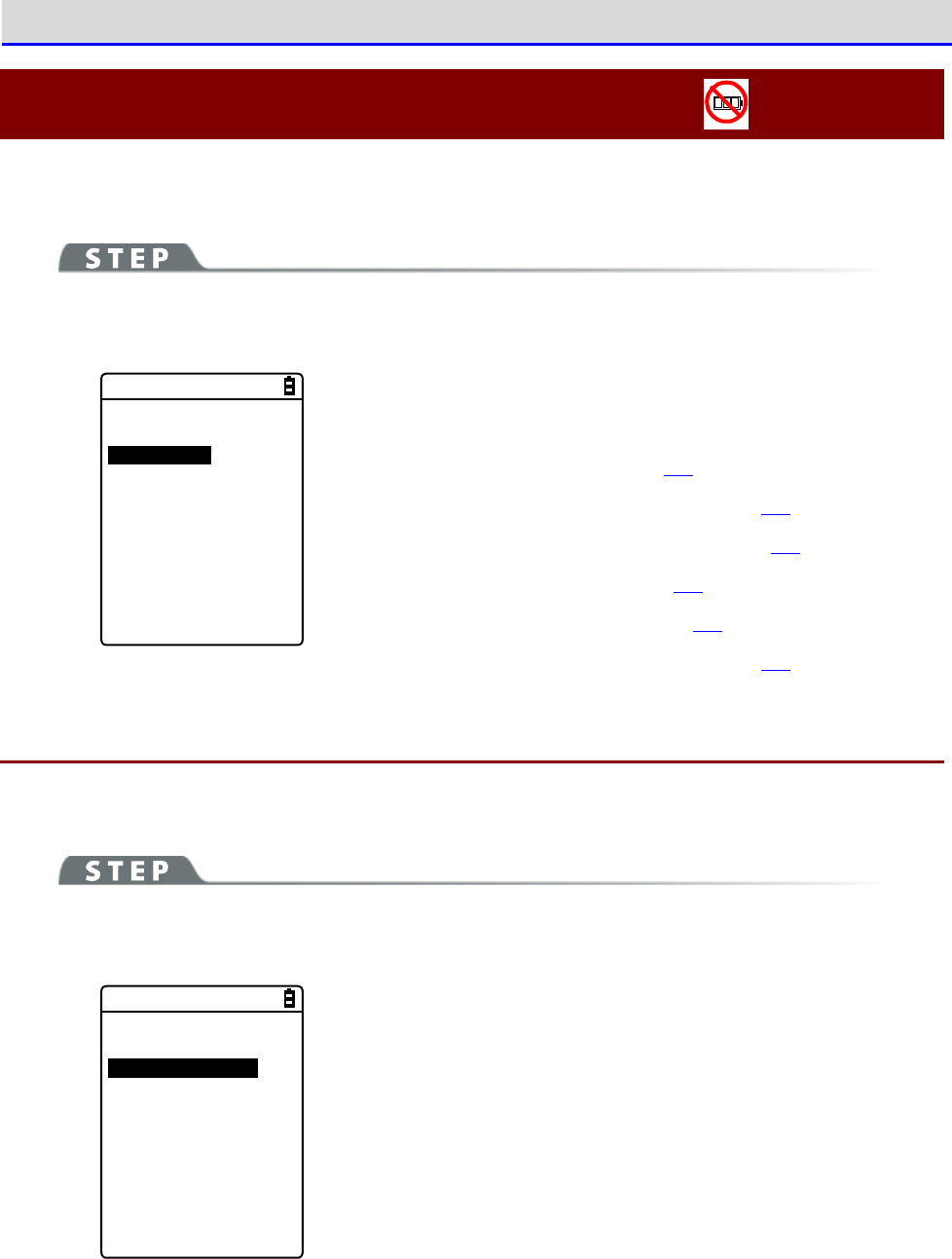
Chapter 4 System Menu 4-11 Test: Testing Hardware Devices
GTX-221-G User’s Manual
200
4-11 Test: Testing Hardware Devices
Use this category to operate hardware devices for testing their conditions.
[System Menu]→[9: Test]
Select the device to test.
< Test >
1:WLAN
2:Bluetooth
3:IrDA
4:Barcode
5:Display
6:Key
Make a selection from the following items:
・WLAN: Test WLAN communication (P.200).
・Bluetooth: Test Bluetooth communication (P.204).
・IrDA: Test infrared (IrDA) communication (P.205).
・Barcode: Test barcode scanning (P.206).
・Display: Test LCD screen display (P.207).
・Key: Test key operations and indicators (P.208).
4-11-1 WLAN: Testing WLAN Communication
Perform WLAN communication-related and IP network communication tests.
[System Menu]→[9: Test]→[1: WLAN]
Select the item to set.
< WLAN Test >
1:Configuration
2:WLAN/ping test
3:AP Search
Make a selection from the following items:
・
Configuration: Configure the ping command execution conditions.
・
WLAN/ping test: Test WLAN communication using the ping command.
・AP Search: Search for access points in the neighborhood.
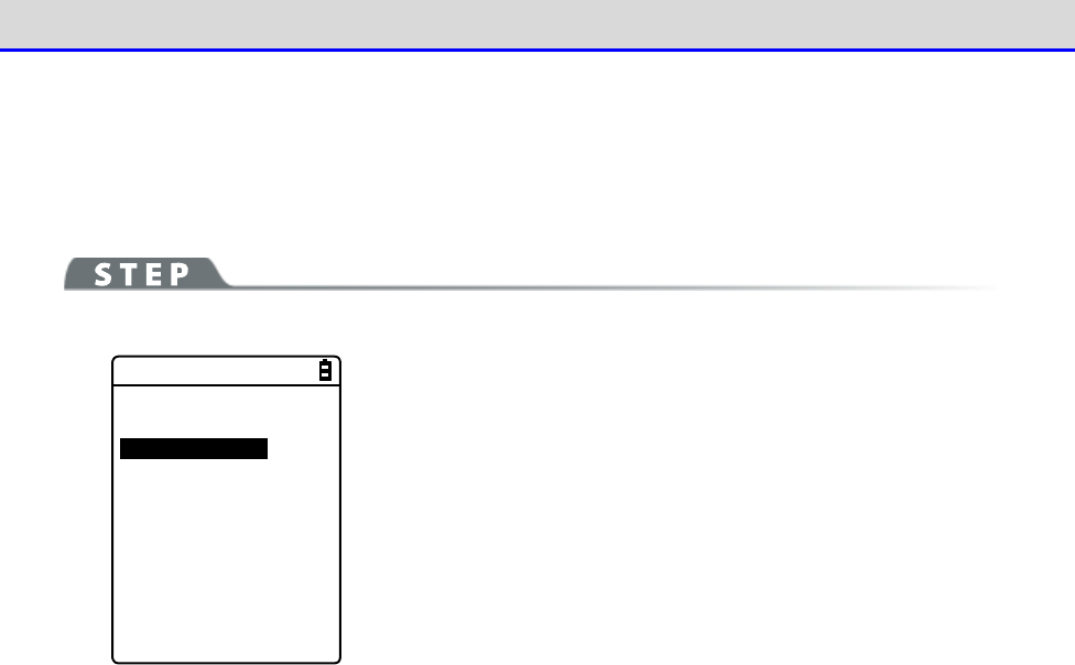
Chapter 4 System Menu 4-11 Test: Testing Hardware Devices
GTX-221-G User’s Manual
201
■Configuration
Configure the ping command execution conditions. WLAN communication will be tested while sending
the ping command.
[System Menu]→[9: Test]→[1: WLAN]→[1:Configuration]
< Configuration >
1:Host address
[000.000.000.000]
2:Packet size
[1472]Bytes
3:Timeout time
[003]sec
4:Trial count
[004]
Configure the WLAN test conditions.
・Host address
Specify the IP address of the target device whose communication
condition you want to check.
・Packet size (Default=1472 bytes)
Select the size (bytes) of a data packet to send.
Settable values: 32, 64, 128, 256, 512, 1024, and 1472
・Timeout time (Default=3 seconds)
Set the timeout time in seconds.
Settable values: 1 to 255 seconds
・Trial count(Default=four times)
Set the number of times to send the ping command.
Settable values: 1 to 255 times
When 0 is specified, continue to send the ping command until the
【C】key is pressed.
Chapter 4 System Menu 4-11 Test: Testing Hardware Devices
GTX-221-G User’s Manual
202
■WLAN/ping test
Execute the ping command to test WLAN communication. Continue to send the ping command to the
host IP address set in Configuration. The following details will be displayed: the ping command
result, the MAC address of the synchronized access point, communication quality (LnkQ), the
strength of received radio signals (ASL), and the channel used.
[System Menu]→[9: Test]→[1: WLAN]→[2:WLAN/ping test]
< WLAN/ping >
Host=000.000.000.000
Time < 000.000 msec
No.00000 1472Bytes
LnkQ
CH:11
ASL
AP_MAC[000000000000]
The following information will be displayed:
<1st line> The title of this test
<2nd line> The host IP address to send the ping command to
<4th line> Displays the result.
When successful
Displays the time expended to obtain the result.(Unit:
msec)
Timeout
Displays "ping Timeout".
When stopped by pressing the【C】key.
Displays "Stopped".
<5th line> Transmission packet number (incremented by 1) and
transmitted bytes
<6th line> Displays the LnkQ indicator.
LnkQ indicates the communication quality between the
product and the access point.
<7th line> Displays the currently synchronized channel.
<8th line> Displays the ASL indicator.
ASL indicates the strength of radio signals received from
the access point.
<10th line> Displays the MAC address of the access point connected
via WLAN communication.
Hint
・To obtain stable communication performance, we recommend that the level of the
LnkQ indicator should be 4 or higher.
・For PSK (TKIP/CCMP), an error message appears when authentication fails.
・The LnkQ indicator in the 6th line and the ASL indicator in the 8th line do not
show radio signal strengths accurately. Consider them as approximate radio
conditions.
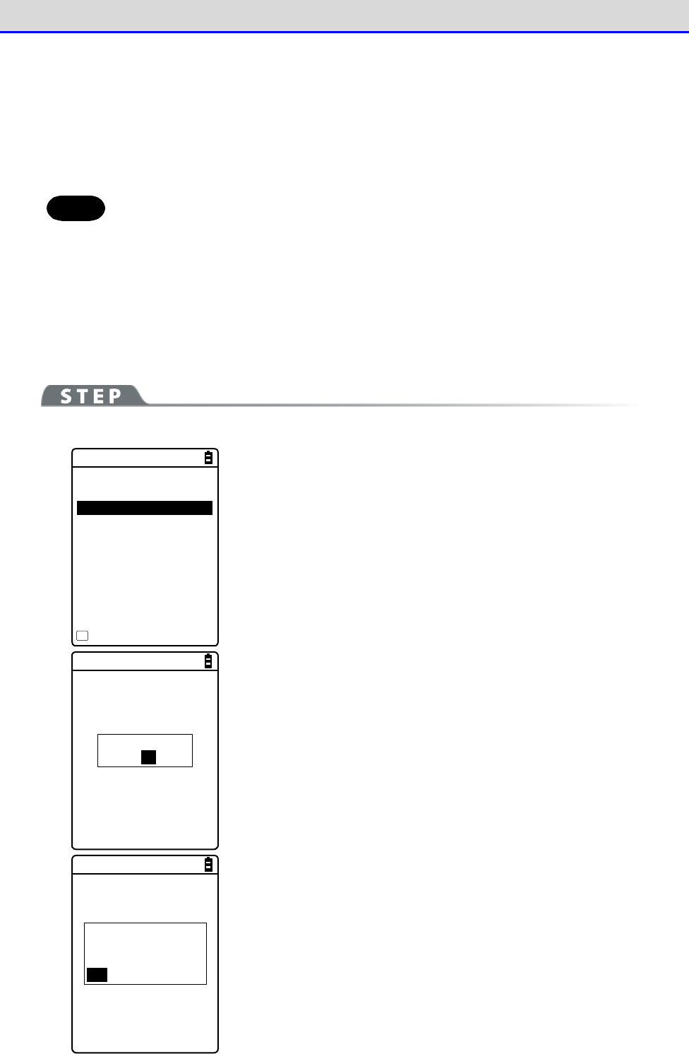
Chapter 4 System Menu 4-11 Test: Testing Hardware Devices
GTX-221-G User’s Manual
203
■AP Search
Search for access points that match the SSID set in the Handy Terminal.
By setting the SSID of the Handy Terminal as "ANY", you can search for all the access points
in the neighborhood.
Hint
Note that the above is effective only when access points are configured to respond
to "ANY". From the viewpoint of security, response to "ANY" is disabled in some
access points.
The details to be displayed as search results are the MAC addresses, channels, and SSIDs of
the matched access points.
[System Menu]→[9: Test]→[1: WLAN]→[3: AP Search]
< Search results >
00A0F850D7D3 01
00A0F850D7F4 06
00A0F850D7CE 11
Property
F1
Search results will be displayed after several seconds or several
tens of seconds.
<1st line> The title of test results
<3rd line and after> The MAC addresses and channel numbers of
detected access points
<10th line> Key guidance to display SSID.
SSID : XIT220
OK
Press the【F1】key to display the SSID set to the currently selected
access point.
Would you like to
set SSID to
XIT220?
YES NO
When the access point is selected, a confirmation dialog box
appears, so that you can set the SSID that is set to the access point
into the Handy Terminal.
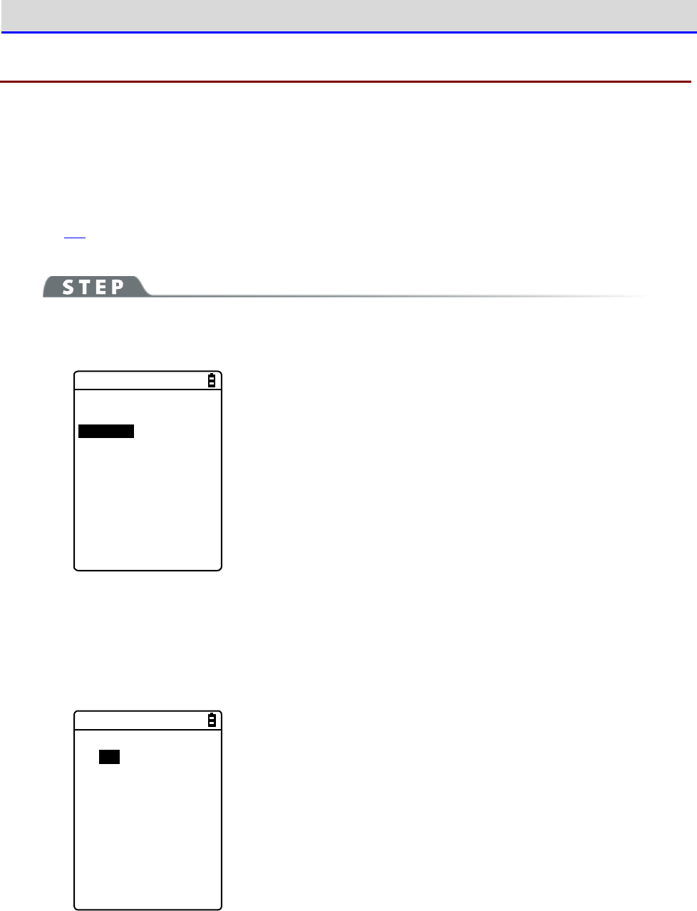
Chapter 4 System Menu 4-11 Test: Testing Hardware Devices
GTX-221-G User’s Manual
204
4-11-2 Bluetooth: Testing Bluetooth Communication
Perform one-to-one communication with another terminal via Bluetooth..
Before executing Bluetooth communication, you have to set the target device as the default device.
(The target device means a slave device or terminal when your device is set as Master, or a
master device when your device is set as Slave.)
「Refer to "4-9-3 Bluetooth: Registering and Setting the Bluetooth Device"-"■Remote device"
(P.171).
[System Menu]→[9: Test]→[2: Bluetooth]
①
Set the Handy Terminal as Master or Slave.
< Role >
1:Master
2:Slave
Select the method for connection with the Bluetooth device to
communicate to.
A master has the initiative in connection, and a slave follows the
instructions of its master. Connection is possible only between a
master and a slave.
Start a test based on the following: when the local device is a
master, the other device is its slave, and when the local device
is a slave, the other device is its master.
Note that this master-slave relationship applies just temporarily
at the time of connection.
The master-slave relationship will disappear after connection.
②
A communication test starts.
< Bluetooth test >
123456
When a key is pressed, the corresponding key data is sent and at
the same time, it is also displayed on the screen (local echo).
When the data is received at the other end, it is highlighted on
the screen.
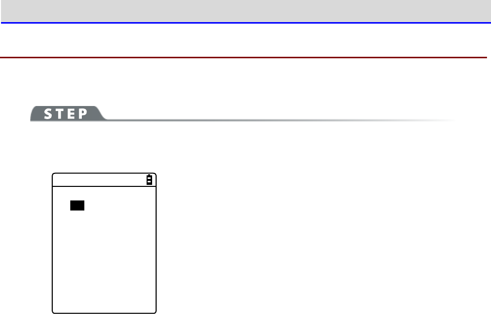
Chapter 4 System Menu 4-11 Test: Testing Hardware Devices
GTX-221-G User’s Manual
205
4-11-3 IrDA: Testing Infrared Communication
Perform one-to-one communication with another terminal via Infrared communication.
[System Menu]→[9: Test]→[3: IrDA]
An infrared communication test starts.
< IrDA test >
000000
Place the infrared communication ports of your device and another
terminal so that they face each other, and start infrared com-
munication also on that terminal.
When a key is pressed, the corresponding key data is sent and at
the same time, it is also displayed on the screen (local echo).
When the data is received at the other end, it is highlighted on
the screen.
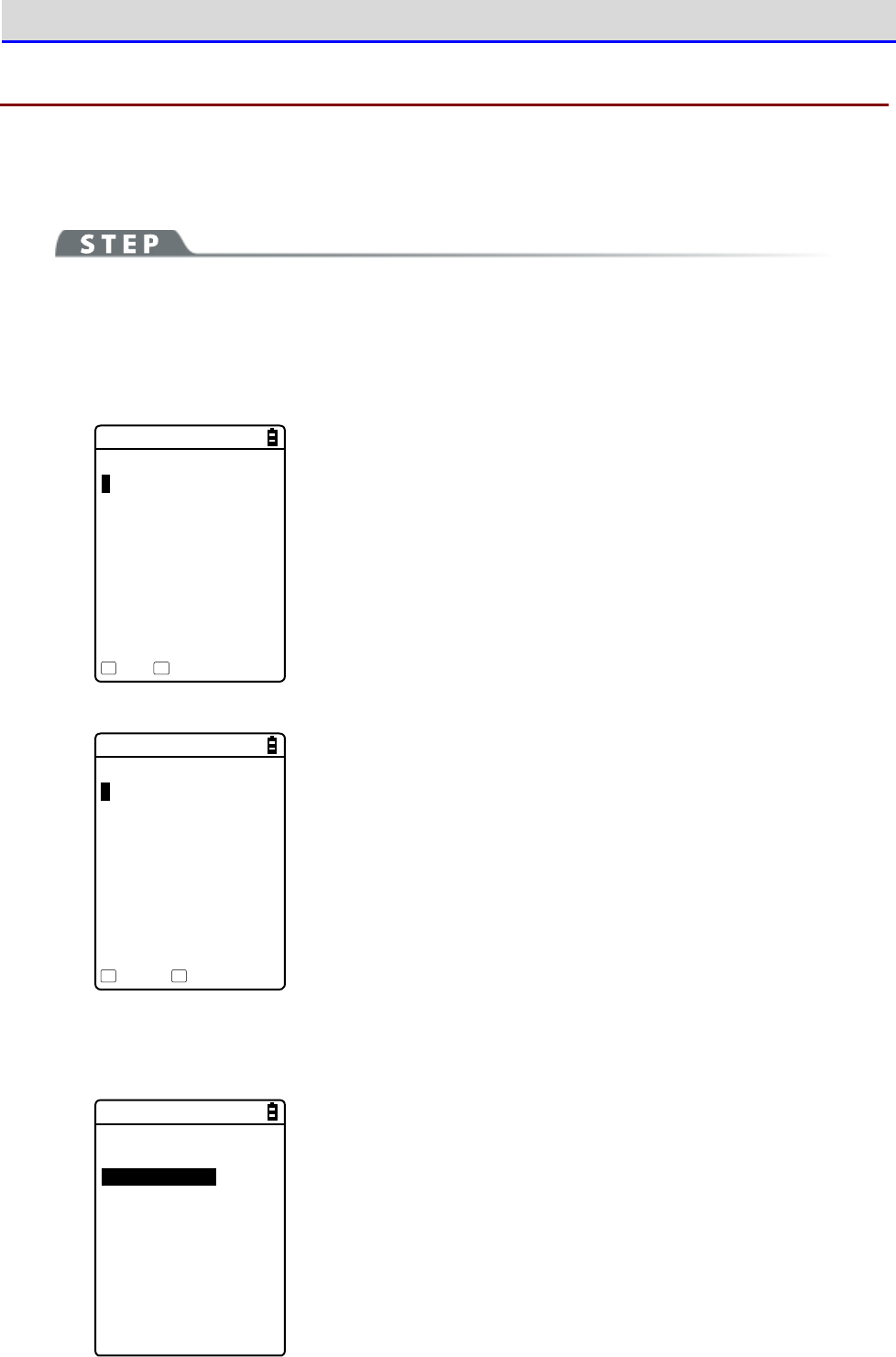
Chapter 4 System Menu 4-11 Test: Testing Hardware Devices
GTX-221-G User’s Manual
206
4-11-4 Barcode
Perform a barcode scanning test.
Note that barcode input here will not be affected by the trigger mode.
[System Menu]→[9: Test]→[4: Barcode]
When the scan mode arises, press the【SCAN】key or the Trigger key to scan a barcode.
●Barcode scanning
< Barcode test >
4901744551846
JAN13 13Bytes
HEX Option
F1 F2
Scan a barcode.
The scanned barcode, barcode type, and the number of digits will
be displayed.
●Display through character code conversion
< Barcode test >
34393031373434353531
383436
JAN13 13Bytes
ASCII Option
F1 F2
Press the【F1】key to display the scanned data through character
code conversion.
・ASCII(Default)
Display the scanned data by converting it into ASCII characters.
・HEX
Display the scanned data by converting it into hexadecimal values.
Through hexadecimal conversion, one character is displayed using
two hexadecimal digits such as "35" for "5" and "6D" for "m".
Press the【F1】key to alternate the display methods.
■Barcode Option
< Barcode option >
1:Check digit
2:JAN/EAN/UPC
3:Composite
Press the【F2】key to set barcode option items.
Note that the settings made here are enabled during barcode test
only.
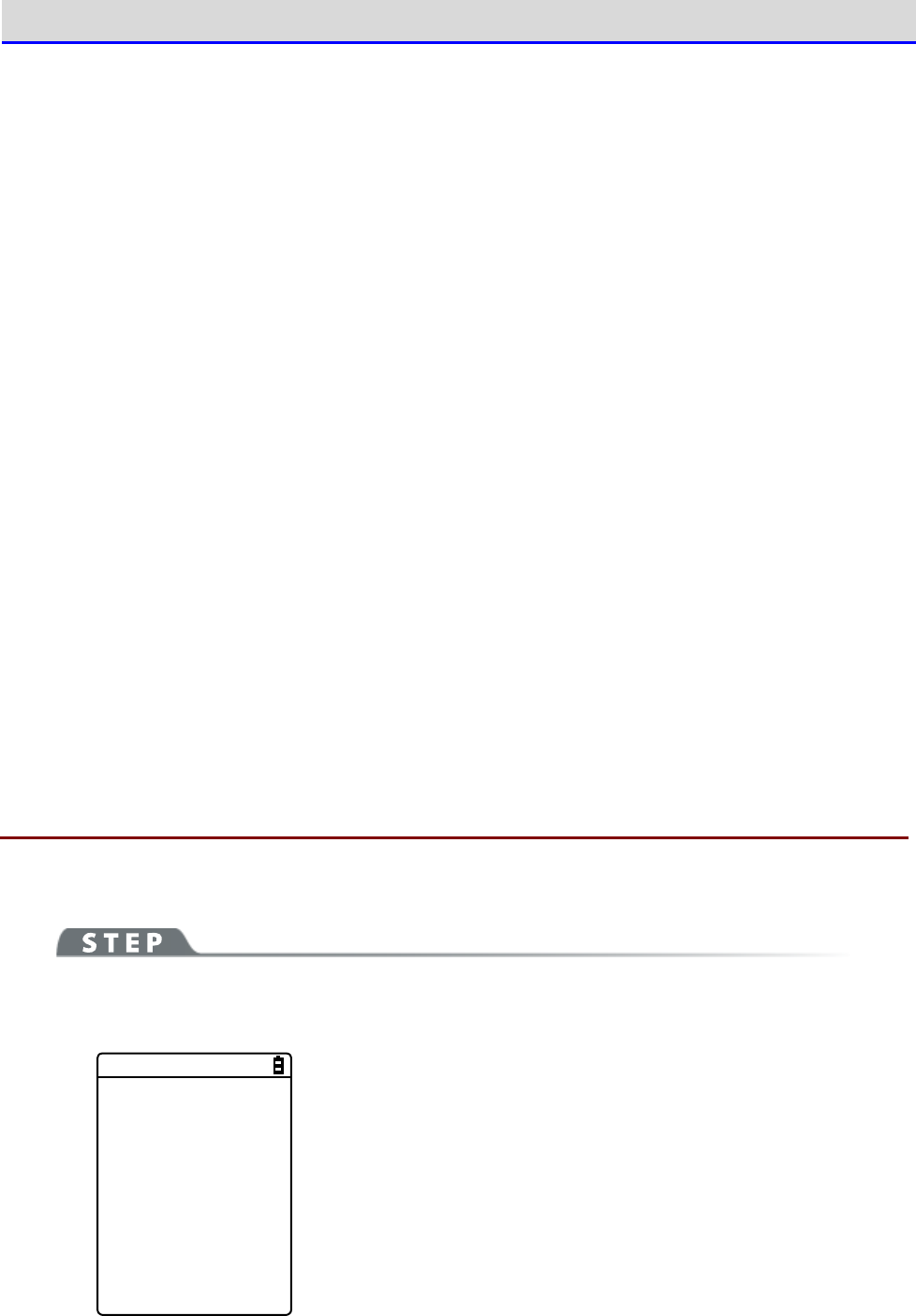
Chapter 4 System Menu 4-11 Test: Testing Hardware Devices
GTX-221-G User’s Manual
207
●Check digit
Set whether to check the check digit.
•
Check Enable not marked (Default)
Do not check the check digit.
•
Check Enable marked
Check the check digit.
●JAN/EAN/UPC
Set the scanning condition for add-on codes of JAN/EAN/UPC.
•
Ignore Add-on (Default)
Do not scan add-on codes.
•
Read all
Allow JAN/EAN/UPC to be scanned regardless of whether add-on codes exist.
•
Read Add-on only
Allow only JAN/EAN/UPC with add-on codes to be scanned.
●Composite
Set the scanning condition for Composite.
•
Prohibition (Default)
Do not allow Composite to be scanned.
•
Permission
Allow Composite to be scanned.
4-11-5 Display: Testing the LCD Screen
Test the screen display condition.
[System Menu]→[9: Test]→[5: Display]
A test pattern is displayed.
Display test starts
Hit any key.
Test the LCD display condition.
Each time a key other than【F4】and【PW】is pressed, the LCD screen
changes its color one after another.
When you finish displaying all colors, you return to the previous
operation.
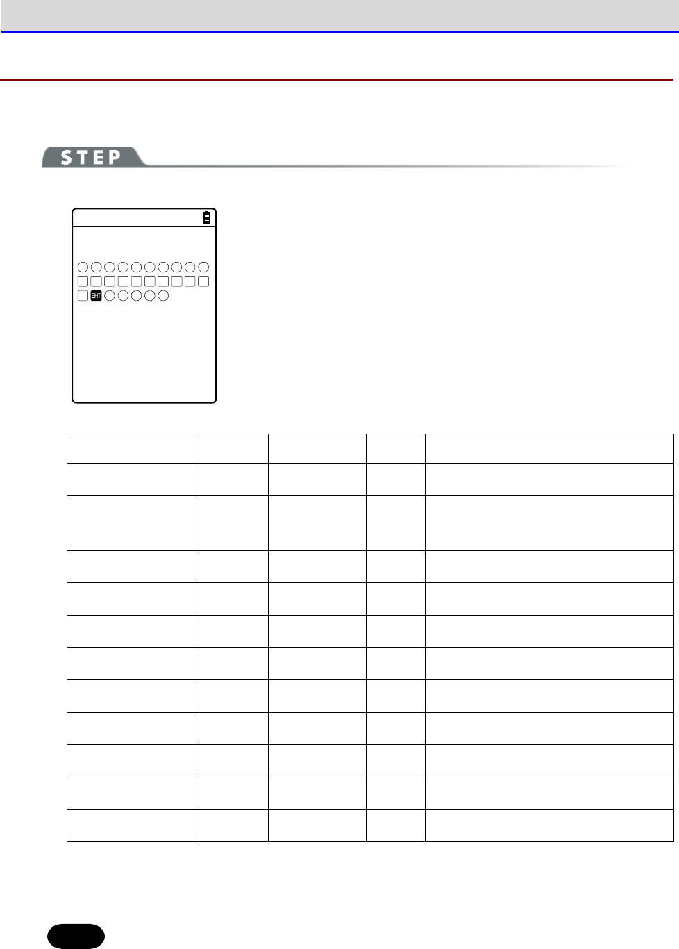
Chapter 4 System Menu 4-11 Test: Testing Hardware Devices
GTX-221-G User’s Manual
208
4-11-6 Key: Testing Key Operations and Indicators
Test key input operations as well as indicators (buzzer/vibrator/LED).
[System Menu]→[9: Test]→[6: Key]
< Key test >
F1 F2
T
F3 F4 F5 F6 F7 F8
L R
1 2 3 4 5
c.
SF
6 7
BS PH
8 9 0
When a key is pressed, the icon for that key displayed above the
partition line in the middle of the screen is highlighted (for the
【ENT】key only, its icon, which is highlighted by default, ceases
to be highlighted), and the icon corresponding to the pressed key
is displayed below the partition line (local echo).
And, in conjunction with each key, the indicators corresponding to
it operate.
The indicators assigned to each key are as follows:
Key
Buzzer
Vibrator
LED
Audio playback
【0】~【9】,【・】
○
×
Green
×
【ENT】,【C】.
【BS】,【SF】
○
×
Orange
×
【SCAN】
×
○
Orange
×
【F1】
○
×
Red
Melody
【F2】
○
×
Red
Voice (Scan the barcode.)
【F3】
○
×
Red
Voice (Charge the battery.)
【F4】
○
×
Red
Voice (An error occurred.)
【
⊳
】(【F5】)
○
×
Red
Voice (Five)
【
】(【F6】)
○
×
Red
Voice (Six)
【
】(【F7】)
○
×
Red
Voice (Seven)
【
】(【F8】)
○
×
Red
Voice (Eight)
When the【C】key has been pressed twice or when every key has been pressed, the test becomes
complete.
Hint
You cannot operate the【PW】key until you finish testing all the keys.

Chapter
5
Specification
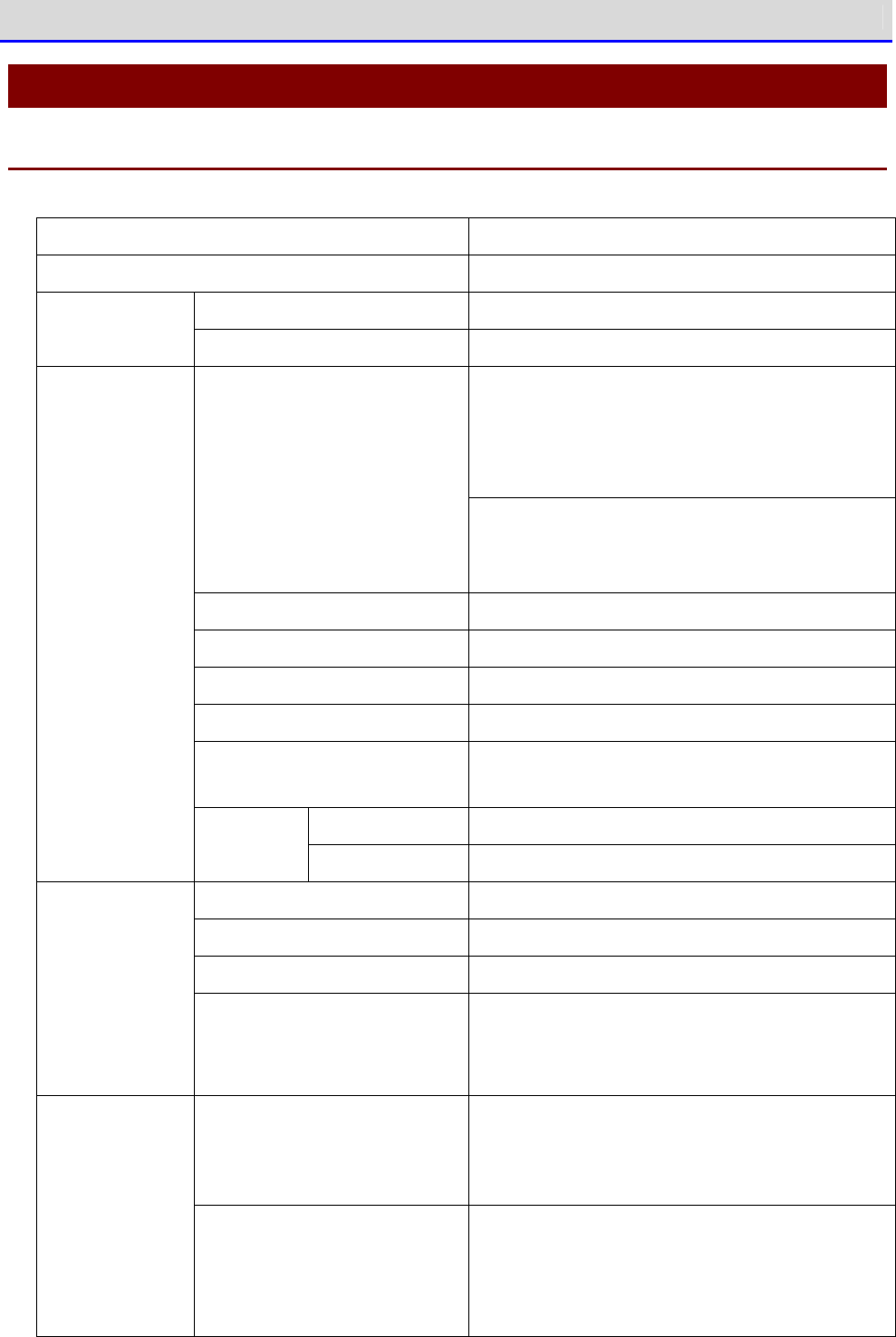
Chapter 5 Specification 5-1 Product Specifications
GTX-221-G User’s Manual
210
5-1 Product Specifications
5-1-1 GTX-221-G Wireless Two-Dimensional Handy Terminal
CPU 32-bit RISC CPU
OS μITRON
ROM 32MB (User area 12MB or more) Memory
RAM 64MB (User area 12MB or more)
NW-7, Code39, JAN-13/8, UPC-A/E,
Industrial 2of5
ITF, Code93, Code128, GS1-128,
GS1 DataBar(RSS)
Decoded barcodes
QR, Micro QR, PDF417, Micro PDF417, MaxiCode,
DataMatrix,
EAN/UCC Composite(GS1 DataBar Compisite),
Light source Red semiconductor laser
Laser class IEC60825 Class2 compliant
Maximum output 1mW
Wave length 655
±
10nm
PCS
0.45 or larger (reflection factor of space and
margin, 70% or more)
One-dimensional
0.127mm
Scanner section
Resolution
Two-dimensional
0.25mm
Display device TFT, Color LCD, 262,144 colors
Number of displayed pixels QVGA(320×240)
Display size 2.4 inches
LCD display
section
Backlight White LED
5-step luminosity adjustment (4-step adjust
ment
and light-off)
Font size 30 dots: 16 single-byte digits×9 lines
24 dots: 20 single-byte digits×12 lines
16 dots: 30 single-byte digits×18 lines
Font
Displayed characters JIS level 1 and level 2 kanji, ANK, symbols,
gaiji (external characters)
(Double-sized width, double-sized height, and
quadruple-size available)

Chapter 5 Specification 5-1 Product Specifications
GTX-221-G User’s Manual
211
Number of keys 27keys(left and right trigger keys included) Key input sec-
tion Backlight Orange
Illuminance sensor
Available (LCD luminosity, key backlight ON/OFF
control)
Battery cover open/close detection Available (a warning screen appears when the
battery cover is removed.)
SCAN Green/red/orange (user-specified, battery
level display)
Displayed LEDs
ALARM Orange (No signal LED)
Speaker 8-step volume adjustment (7-
step adjustment and
OFF)
Sound when scanning and when errors of var
ious
types occur (can be specified by the user).
Vibrator Generate vibrations: when scanning and when
errors of various types occur (can be specified
by the user).
Complied interna-
tional standards
Bluetooth Ver2.0+EDR compliant
Complied domestic
standards
ARIB STD-T66
Communication
method
Spread spectrum method (frequency hopping
method)
Radio frequency 2.4GHz band
Baud rate Maximum 1Mbps (theoretical)
Transmission power
Class
Class2
Antenna Built in the main unit.
Transmission
distance
Maximum 10m
*1
Bluetooth
Profile SPP
Complied interna-
tional standards
IEEE802.11b/g
Complied domestic
standards
ARIB STD-T66/RCR STD-33A
Communication
method
Direct-sequence spread spectrum (DSSS)
Orthogonal frequency-division multiplexing
(OFDM)
Communication
section
WLAN
Radio frequency 2.4GHz band

Chapter 5 Specification 5-1 Product Specifications
GTX-221-G User’s Manual
212
Baud rate OFDM: 54/48/36/24/18/12/9/6 Mbps
DSSS: 11/5.5/2/1 Mbps
Number of
channels
OFDM:13ch
Encryption
standard
Authentication
method
Encryption
method
WEP(40/128) OPEN, SHARED WEP(40/128)
WPA-PSK
(compatible)
TKIP
WPA2-PSK
(compatible)
PSK
CCMP(AES)
WPA (com-
patible)
TKIP
Security
WPA2 (com-
patible)
EAP-TLS
EAP-PEAP-MSC
HAPV2 CCMP(AES)
Antenna Built in the main unit.
Transmission
distance
Indoor: maximum 75m, Outdoor: 200m
IrDA IrDA Ver1.2 Physical Layer compliant
Baud rate: maximum 115,200bps (SIR)
Management function SNMP Agent
Supported MIB MIB-
Ⅱ
(RFC1213), Welcat Enterprise MIB
External con-
nection
terminal
microSD SD Memory Card Specification, Ver.1.1
Dimensions 58 (W)
×
171 (D)
×
45 (H)mm
Grip section 45 (W)
×
29 (H)
Weight 225g (battery pack included)
Main unit charging function Available (with temperature protection func-
tion)
Main battery Li-ion rechargeable battery
*2
Power supply
Backup battery Li-ion rechargeable battery (maintenance-free)
Hours of continuous use
※3
Approx. 11 hours (Typ.)
19 days (actual value) Backup time With main battery
(Main battery fully charged)
RAM reten-
tion time
11 to 37 days (guaranteed value
at normal temperature)
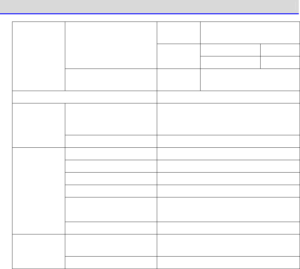
Chapter 5 Specification 5-1 Product Specifications
GTX-221-G User’s Manual
213
RAM reten-
tion time
15 hours or longer
No RAM retention One year
Without main battery
(Backup battery
fully charged) RTC reten-
tion time RAM retention Six months
Backup battery charged Charging
time
One day
Charging time Approx. 2.5 hours
Functionality Year (4 digits), month, day, hour, minute,
second/with leap-year correction, timer
functionality available
Clock function
Difference per month Approx.
±
30 seconds
Operating temperature -5
℃
~45
℃
Operating humidity 20 to 80% RH (No condensation)
Storage temperature -10
℃
~60
℃
Storage humidity 10 to 90% RH (No condensation)
Illuminance conditions Artificial light: up to 4,000 lx
Sunlight: up to 80,000 lx
Environment
RoHS instructions Complied
Drop resistance
1.5m (for each of the six sides of the main unit,
five drops on concrete tested)
*4
Durability
Water and dust proof IEC IP54
*1 For stable communication, we recommend using the Handy Terminal within 2 m away from the
target, with no obstruction between the terminal and the Bluetooth USB adapter or the
Bluetooth communication unit.
*2 When deeply charged repeatedly, the main battery may reach its end of life due to capacity
reduction caused by deterioration.
*3 Hours of continuous use are an actual value under the following conditions:
One second of barcode reading per 20 seconds, one WLAN transmission/reception
LED ON, speaker ON, luminosity: level 2, vibrator OFF
*4 A value obtained by testing, not a guaranteed value.
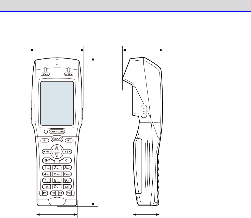
Chapter 5 Specification 5-1 Product Specifications
GTX-221-G User’s Manual
214
■Dimensions
58 45
45 29
171
Chapter 5 Specification 5-1 Product Specifications
GTX-221-G User’s Manual
215
5-1-2 QC-006 Single Charger
Operating
temperature
0~40
℃
Operating hu-
midity
20~80% (No condensation)
Storage
temperature
-10
℃
~60
℃
Storage hu-
midity
10~90% (No condensation)
Charging time
Approx. 2.5 hours
※
Depending on the battery condition or the use env
ironment,
the required charging time may become longer.
Dimensions 93 (W)×117.5 (D)×105.4 (H)mm
Charging
section
Weight 225g
Rated input AC100 to 240V 50-60Hz 75VA
Rated output DC5.5V 2.5A 13.75W
Weight 180g (AC cable not included)
Dimensions 41.5 (W)×90 (D)×28 (H)mm
(Power cable, DC cable not included)
AC cord length
1.8m
AC adapter
DC cord length
1.8m
Chapter 5 Specification 5-1 Product Specifications
GTX-221-G User’s Manual
216
5-1-3 QC-007 Multi Charger
Operating temperature 0~40
℃
Operating humidity 20~80% (No condensation)
Storage temperature -10
℃
~60
℃
Storage humidity 10~90% (No condensation)
Charging time Approx. 2.5 hours
*
Depending on the battery condition or the use
environment, the required charging time may
become longer.
Dimensions 375.5 (W)×120 (D)×106 (H)mm
Charging
section
Weight 910g
Rated input AC100 to 240V 50-60Hz 150VA
Rated output DC12V 4.6A 70W
Weight 300g (AC cable not included)
Dimensions 58 (W)×132 (D)×30 (H)mm
(Power cable, DC cable not included)
AC cord length 1.8m
AC adapter
DC cord length 1.8m
5-1-4 IU-004 USB Communication Unit
Operating
temperature
0~40
℃
Operating humidity 20 to 80% (No condensation)
Storage temperature -10
℃
~60
℃
Storage humidity 10 to 90% (No condensation)
Dimensions 93 (W)×117.5 (D)×105.4 (H)mm
General
Weight 215g
USB cable length 1m
Infrared communication IrDA Ver.1.2 Physical Layer compliant
Baud rate: maximum 115,200bps
External interface USB2.0 Full Speed
Connector: TYPE B
Power supply USB BUS power
Communication
section
Current consumption 100mA or less

Chapter 5 Specification 5-1 Product Specifications
GTX-221-G User’s Manual
217
5-1-5 IU-004C USB Communication/Charging Unit
Operating temperature 0~40
℃
Operating humidity 20~80% (No condensation)
Storage temperature -10
℃
~60
℃
Storage humidity 10~90% (No condensation)
Dimensions 93 (W)
×
117.5 (D)
×
105.4 (H)mm
General
Weight 216g
USB cable length 1m
Infrared communication IrDA Ver.1.2 Physical Layer compliant
Baud rate: maximum 115,200bps
External interface USB2.0 Full Speed
Connector: TYPE B
Power supply USB BUS power
*
Communication
section
Current consumption 100mA or less
Charging sec-
tion
Charging time Approx. 2.5 hours
*
Depending on the battery condition or the use
environment, the required charging time may
become longer.
Rated input AC100 to 240V 50-60Hz 75VA
Rated output DC5.5V 2.5A 13.75W
Weight 180g (AC cable not included)
Dimensions 41.5 (W)×90 (D)×28 (H)mm
(Power cable, DC cable not included)
AC cord length 1.8m
AC adapter
DC cord length 1.8m
*Used to supply power to the communication function. Use the AC adapter for charging.
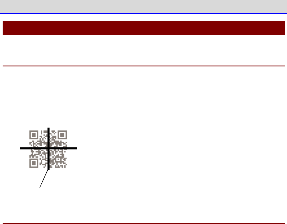
Chapter 5 Specification 5-2 Scan Specifications
GTX-221-G User’s Manual
218
5-2 Scan Specifications
5-2-1 How to Scan Barcodes
When scanning a barcode, cross-shaped laser beams (aiming pattern) are irradiated. Align the
center of an aiming pattern with a barcode for scanning.
During scan, the illumination LED is lighted ON. However, in a bright environment or when
continuously scanning the same barcode, it may be lighted OFF.
Aim in g pa ttern
5-2-2 Scan Depth
Depending on the barcode type, the scannable distance may change.
When scanning is difficult, change the distance between the barcode and the main unit and try
again.
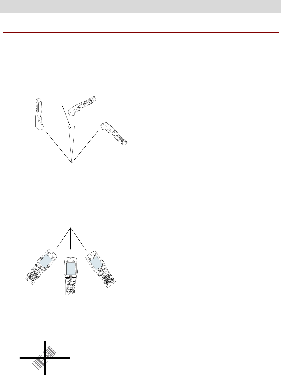
Chapter 5 Specification 5-2 Scan Specifications
GTX-221-G User’s Manual
219
5-2-3 Barcode Skew and Scannable Angle
When a laser light is irradiated perpendicularly to a barcode, scanning may become difficult
due to specular reflection (dead zone).
In such a case, change the scanning angle and try again.
Bar co d e
D ea d zo n e
When scanning diagonally from the left or right in relation to a barcode, it may become difficult
to perform a scan. In such a case, change the angle to scan a barcode.
Bar co d e
Scanning can be performed at all angles (360 degrees).
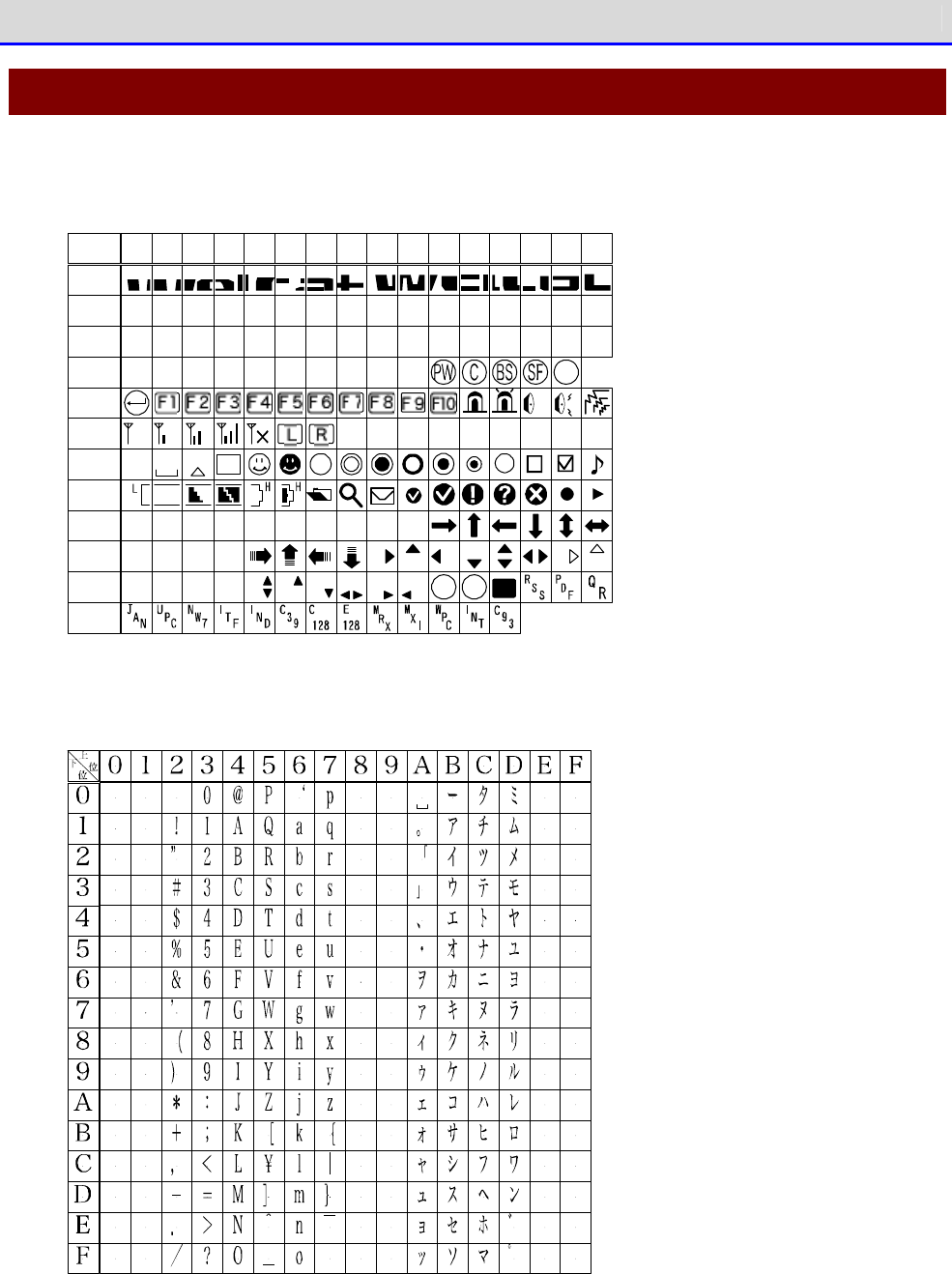
Chapter 5 Specification 5-3 Characters to Output on Screen
GTX-221-G User’s Manual
220
5-3 Characters to Output on Screen
■Double-Byte Characters
( 1)
f 0 4 0
0 1 2 3 4 5
6 7
8
9
A B C D E
F
f 0 5 0
f 0 6 0
f 0 7 0
f 0 8 0
f 0 9 0
f 0 a 0
f0 b 0
f0 c0
f0 d 0
f0 e0
f0 f0
( 0) ( 2)( 3)( 4)( 5)( 6)( 7)( 8)( 9) ・
S
NUSHSXEXET
DLD1D2D3D4
EQAKBL
NKSYEBCNEMSB
BSHTLFVTFFCRSO
ECFSGSRSUS
SI
0
T
シフト
JIS
ENT
■Single-Byte Characters

Chapter
6
FAQs and Answers
Chapter 6 FAQs and Answers 6-1 FAQs and Answers
GTX-221-G User’s Manual
222
6-1 FAQs and Answers
This section explains FAQs and trouble, and explains items required to check and sections to
refer to for troubleshooting.
Q: The power cannot be turned ON.
■
Make sure that the electrodes of the Handy Terminal
and battery pack have not been soiled
or deformed.
■
Make sure that the battery pack is correctly attached.
■
Make sure that the battery pack is charged sufficiently.
■
Make sure that the battery cover is correctly attached.
■
To turn the power ON for the first time after re-attaching the battery pack, hold down the
【PW】key for two seconds or longer.
r
rr
re
ee
ef
ff
f
"1-2 How to Use the Main Unit" (P.34)/ "1-4 How to Clean the Main Unit" (P.57)
Q: Nothing is displayed on the screen.
■
Make sure that the electrodes of the Handy Terminal
and battery pack have not been soiled
or deformed.
■
Make sure that the battery pack is correctly attached.
■
Make sure that the battery pack has not run out of power.
■
Make sure that the battery cover is correctly attached.
r
rr
re
ee
ef
ff
f
"1-2 How to Use the Main Unit" (P.34)/ "1-4 How to Clean the Main Unit" (P.57)
<If the problem cannot be solved even after confirming the above>
Take the following procedure to start the system menu.
1.
Remove the
battery cover and
battery pack.
2.
Wait for 10 seconds, then attach the battery pack and battery cover.
3.
Hold down the【PW】key for two seconds or longer while holding down the【SCAN】key.
Chapter 6 FAQs and Answers 6-1 FAQs and Answers
GTX-221-G User’s Manual
223
Q: After suspending the operation for a while, the power is turned OFF.
■
Make sure that the battery pack is not old.
The battery pack has its life. The battery pack'
s capacity gradually reduces as the battery
pack is used over and over again and as time passes. If the battery pack's usable time becomes
extremely short, the battery pack is supposed to reach its end of life. In such a case, purchase
a new one.
■
Make sure that the battery pack has not run out of power.
r
rr
re
ee
ef
ff
f
"1-2 How to Use the Main Unit" (P.34).
■
Make sure that Auto power off is disabled ------(P.111),
■
Make sure that power saving is not set to the application program.
Q: The product cannot be charged.
■
Make sure that the main unit is correctly placed in the charging cradle.
■
Make sure that the power adapter is correctly placed in the charging cradle.
■
Make sure that charging is performed at an ambient temperature of 0
℃
to 40
℃
.
r
rr
re
ee
ef
ff
f
"1-2-4 Charging the Battery Pack" (P.43)
<If the problem cannot be solved even after confirming the above>
The battery pack may be faulty.
Contact your dealer.
Q: To check or correct the date...
Refer to "4-3-2 Clock: Setting the Time" (P.104).
Chapter 6 FAQs and Answers 6-1 FAQs and Answers
GTX-221-G User’s Manual
224
Q: The system menu does not start.
■
To forcibly start the system menu, press the【PW】key while holding down the【SCAN】key.
r
rr
re
ee
ef
ff
f
"4-1-2 Starting the System Menu" (P.94)
■
If you want the system menu to always start,
Select as[1: System]
→
[1: Auto execute] on the system menu, and select
the [System Menu]
radio button.
r
rr
re
ee
ef
ff
f
"4-3-1 Auto execute: Automatically Executing an Application Program" (P.103)
Q: To change the application program starting up when the power is turned
ON...
■
Select as [1: System]
→
[1: Auto execute]
on the system menu, select the desired application
program's radio button.
r
rr
re
ee
ef
ff
f
"4-3-1 Auto execute: Automatically Executing an Application Program" (P.103)
Q: To start another application program...
■
Select as [5: File]
→
[
1:
Application], and then select [Execute] on the submenu.
r
rr
re
ee
ef
ff
f
"4-7 File: Executing, Uploading, and Deleting Files"-"■Execute: Execute an Applica
tion
Program" (P.156)
Q: A barcode cannot be scanned well.
■
Make sure that scanning is performed on the barcode appropriate for the settings of the
application program.
Depending on the settings of the application program, it is prohibited to scan specific types
of barcodes.
■
Make sure that specular reflection does not occur.
Make sure that the barcode's
surface
is not covered in vinyl or laminated
⇒
eve
n if the
scanning angle is not an angle at which specular reflection occurs, scanning may become
difficult.Change the scanning angle and try again.
■
Make sure to scan the barcode correctly.
There are specifications for the resolution and the scan distance
; perform a scan in the
distance range that meets the minimum widths of barcode bars and spaces.
■
Make sure that the scan distance is correct. (Refer to "5-2 Scan Specifications" (P.218).)
■
Make sure that the quality of the barcode label is good.
・
Otherwise, scanning may not be performed correctly. In any of the following cases, make
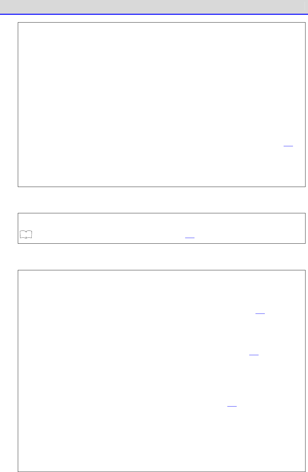
Chapter 6 FAQs and Answers 6-1 FAQs and Answers
GTX-221-G User’s Manual
225
the quality of the barcode label better:
①Faintly printed barcode (as if printed by a dot impact printer or on a carbon copy slip)
②Barcode that is soiled or has missing bars
③
Barcode with the widths of its bars/spaces being too narrow for the resolution of this
product to handle
④
Barcode without left and right blank spaces (quiet zones) (characters or lines exist to the
left and right of the barcode)
⑤Barcode with irregularities in bar and space widths due to smearing or fading
⑥Warped or wrinkled label
・
Change the decoding level setting and try again. For details on the decoding level setting,
refer to "4-9-1 Barcode: Configuring the Barcode Scanner"-"■Decoding level (P.164).
■
Make sure that there is no problem with laser lights.
・
If dirt or dust adheres to the scan window, it may become impossible to scan correctly.
In such a case, wipe the filter at the scan window clean with a dry soft cloth.
Q: To check the drive's free space...
Select as [8: Manage]
→
[4: Drive] to check the free space.
r
rr
re
ee
ef
ff
f
"4-10-4 Drive: Displaying Drive Information" (P.195)
Q: WLAN communication does not work.
■
Make sure that the access point is connected to the Ethernet LAN.
Depending on the access point, WLAN communication does not operate if the LAN cable is
disconnected or a link is not established.
■
Make sure that the SSID setting matches the access point.----(refer to P.114.)
Match the SSID to the access point.
If "ANY" (blank) is set for the SSID in the Handy Terminal
, connection may not be possible
due to the access point's functionality. Refer to the manual for the access point.
■
Make sure that the authentication settings are correct----(refer to P. 116).
Match the authentication method to the access point.
For "Shared", check the WEP settings.
■
Make sure that the WEP settings are correct.
Make sure that the WEP method is correct (disable, 40bit,128bit).
Make sure that the WEP TxKey_ID matches the WEP key (refer to P.116).
■
Make sure that there is no access point for which the s
ame channel or an interfering channel
is set.
When a non-
interfering channel is set, a maximum of four access points can be used in one
area.
■
Make sure that no radio signal is generated that may cause trouble.
Check that there is no device causing trouble such as a WEB camera, radio house-
phone system,
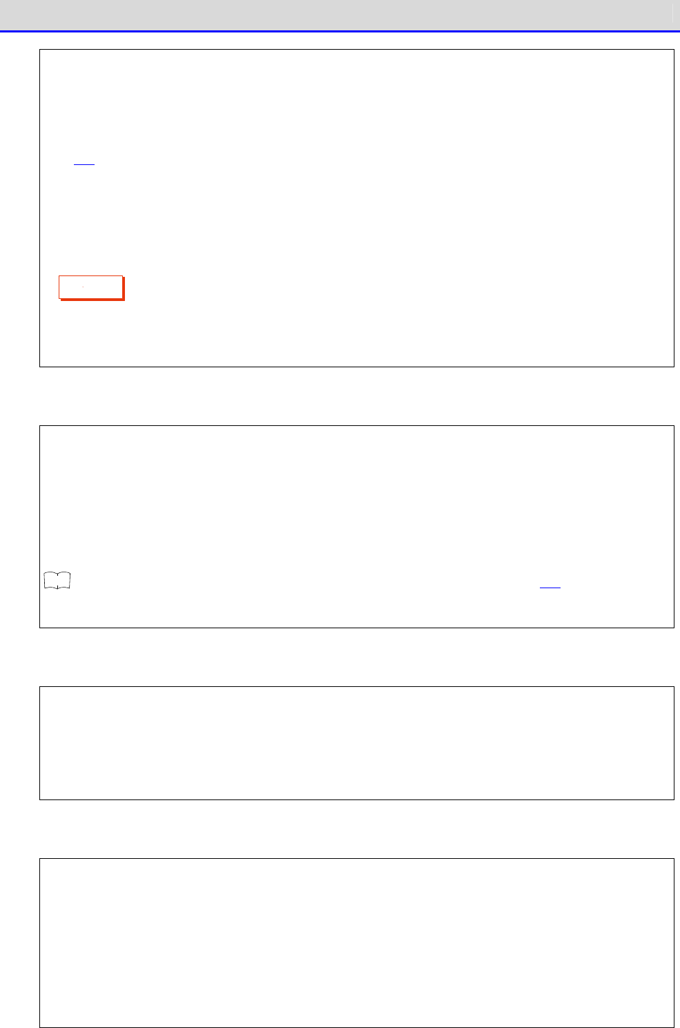
Chapter 6 FAQs and Answers 6-1 FAQs and Answers
GTX-221-G User’s Manual
226
microwave oven, and another WLAN communication.
In addition, PCs may generate noise. Keep PCs 1m or more away from the access point and
the
Handy Terminal.
■
Make sure that there is no problem with the TCP/IP settings such as IP address----(
refer to
P.131).
Check connection to the PC by using the ping command.
■
DHCP fails.
Network Management Tool is not running, or general DHCP is used that does not specify a
particular port number.
C
a
u
t
i
o
n
Network Management Tool uses its own DHCP port number (8067). For that reason, the port number
in the Handy Terminal should match the above.
Q: Bluetooth communication does not work.
■
Make sure that the remote device to connect to is running.
■
Make sure that the remote device to connect to is set as the default device.
Set the above by selecting as [7: Device]
→
[3: Bluetooth]
→
[2: Remote device].
■
Make sure that the main unit has the same security settings as the remote device to connect
to.
r
rr
re
ee
ef
ff
f
"4-9-3 Bluetooth: Registering and Setting the Bluetooth Device" (P.169)
■
Make sure that communication software such as BluePorter is running correctly.
Q: The BluePorter-V COM port does not open.
■
Check if you use our application program called WL7-KEY in the PC with BluePorter-
V embedded
in it.
If the version of WL7-
KEY is Ver1.02 or earlier, the COM port is occupied and cannot be opened.
In such a case, contact your dealer.
Q: Infrared communication (IrDA) does not work.
■
Make sure that the USB cable is connected securely.
■
Make sure that the USB driver software for the USB communication unit (IU-004/004C)
is
installed in the PC to connect to.
■
Make sure that the transfer utility BluePorter-V is installed in the PC to connect to.
■
Make sure that the BluePorter-
V icon is displayed in the notification area at the far right
of the Windows task bar on the screen. Otherwise, even if BluePorter-
V is installed, it is
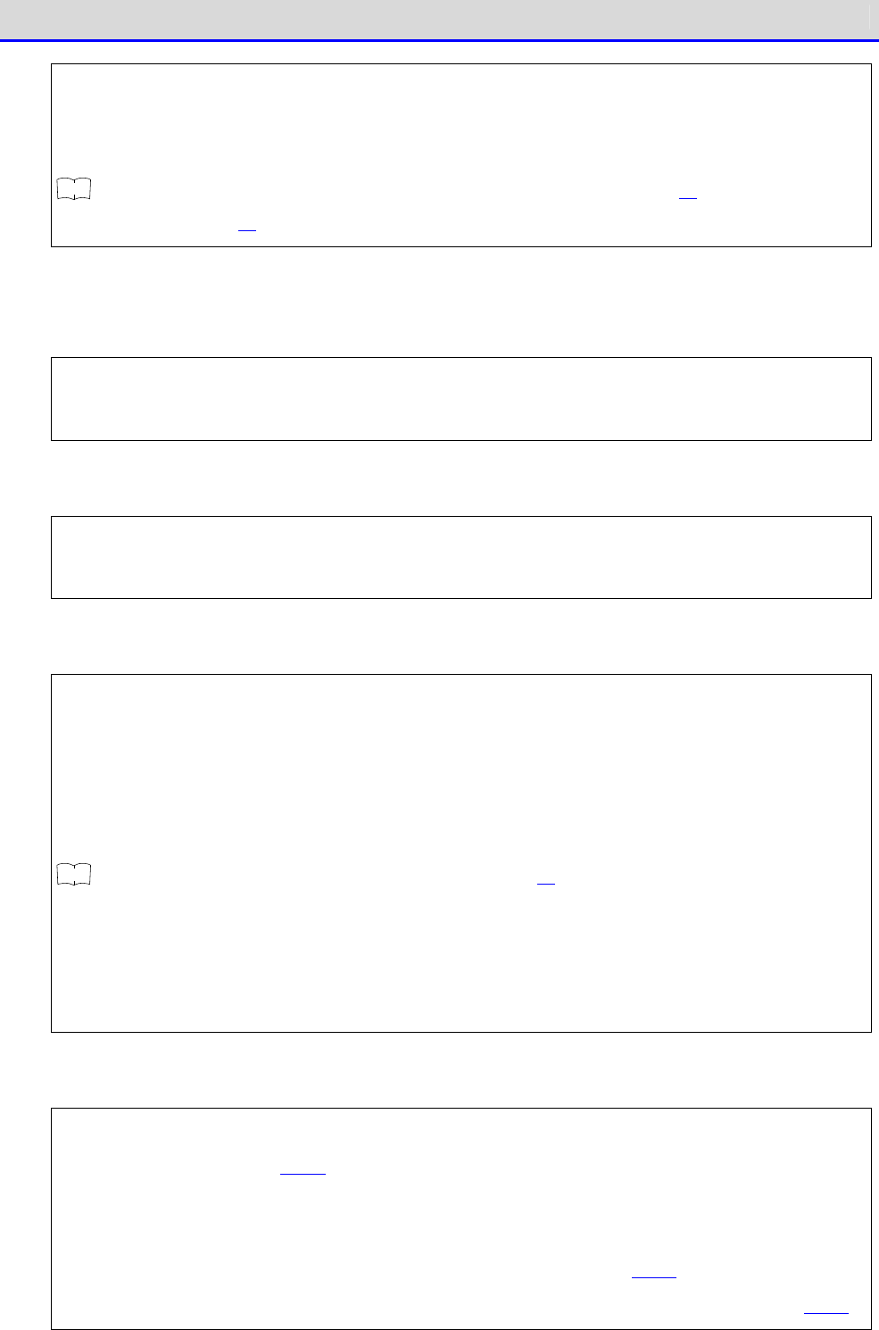
Chapter 6 FAQs and Answers 6-1 FAQs and Answers
GTX-221-G User’s Manual
227
not activated.
■
Make sure that the infrared communication ports (windows) of the Handy Terminal
and the USB
communication unit (IU-004/IU-004C) are not soiled.
r
rr
re
ee
ef
ff
f
"3-4 How to Build an Infrared (IrDA) Communication Environment" (P.81)/ "1-4
How to Clean
the Main Unit" (P.57)
Q: To use WLAN communication and Bluetooth communication together in the
same environment...
You can use both types of communication together, but communication delay may occur due to mutual
radio interference.
Q:
"Writing failure" is displayed while uploading/receiving files.
■
This message appears in such cases as when the free space on the F drive is insufficient.
Delete files on the F drive, S drive, or R drive to increse the free space and then try again.
Q: "Timeout" is displayed while uploading/receiving files.
This message appears when a certain period of time passes in a transmission or reception waiting
state.
■
Make sure that the PC's Network Management Tool is running.
■
Make sure that the communication settings are correct.
■
Make sure that the main unit is connected to the PC correctly.
r
rr
re
ee
ef
ff
f
"3-2 Building WLAN Communication Environment" (P.68)
■
Make sure that the PC's resources are sufficient.
If a communication softwar
e application program (Network Management Tool or BluePorterV) is
running, file transmission or reception may fail due to PC resource shortage. Terminate
application programs not necessary for communication as much as possible and try again.
Q:
"Connection failure" is displayed while uploading/receiving files.
■
Make sure that the WLAN communication settings are correct----(refer to "4-4
WLAN: WLAN
Communication Settings
" P.114).
■
Make sure that FTP server software is running on the PC.
■
Make sure that the access point (a device recommended by us) and the PC are connected correctly
on the LAN----(refer to "4-4
WLAN: WLAN Communication Settings
" P.114).
■
Make sure that the FTP settings are correct----("3-5-3 FTP: FTP Settings" (refer to P.136).
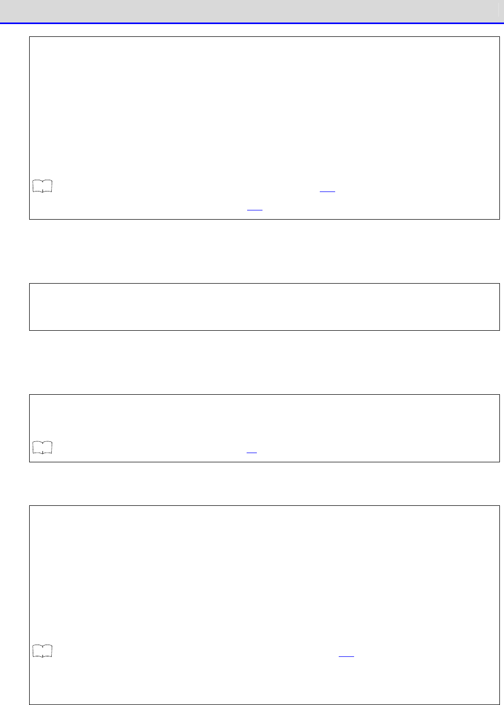
Chapter 6 FAQs and Answers 6-1 FAQs and Answers
GTX-221-G User’s Manual
228
■
When Bluetooth is selected, make sure that the remote device to connect to is the target remote
device.
■
When Bluetooth
is selected, make sure that the same security settings as the remote device
are applied.
■
When Bluetooth is selected, make sure that the remote device is set correctly.
■
Make sure that the PC is not using a file with the same name (such as a file being
opened
by editor software or opened by some database operation).
r
rr
re
ee
ef
ff
f
"4-8 ID: Setting the Terminal Identification ID" (P.163)/ "4-9-3
Bluetooth: Registering
and Setting the Bluetooth Device" (P.169)
Q: To collectively configure settings for the Handy Terminal such as IP
address from the PC...
■
Using the DHCP Server of Network Management Tool in the WebGlider Integrated Server (optional)
package, settings for the Handy Terminal can be automatically configured.
Q: Application programs cannot be activated or files cannot be uploaded
or received.
■
Some functionality does not operate if the battery pack voltage is too low. Make sure that
the battery pack is charged sufficiently.
r
rr
re
ee
ef
ff
f
"1-2-4 Charging the Battery Pack" (P.43)
Q: Files are corrupted.
■
Files can get corrupted in the following situation: while files are being written to (during
data communication, file reception, file backup, etc.) or being
defragmented, the battery
pack is removed, or the product is mistakenly dropped or receives strong impact and eventually,
the power gets turned OFF.
Either delete such files or transfer them to a PC for data recovery.
If the product does not operate cor
rect even after the above, it is suspected that the product
becomes faulty. In such a case, ask for repair.
r
rr
re
ee
ef
ff
f
4-7 File: Executing, Uploading, and Deleting Files" (P.152)
■
Some application program processes defragmentation or
backup before turning the power OFF.
When replacing the battery pack, make sure that the power is turned OFF.
Chapter 6 FAQs and Answers 6-1 FAQs and Answers
GTX-221-G User’s Manual
229
Q: The system settings of the Handy Terminal are initialized.
■
Since the initial settings are stored in the registry file, if file corruption
as above occurs,
initialization may be performed.
Q: When the power is turned ON, the message "SDrive has been initialized."
is displayed.
■
During operation, if the battery pack or battery is removed or if the power is turned OFF
due to drop impact, etc
., normal termination will not be performed and data on the S drive
will not be backed up.
■
The same message appears when the product is powered ON for the first time after purchase.
Q: When the power is turned ON, the system menu starts up.
■
Make sure that the application program name (******. OUT) is selected after selecting as [1:
System]
→
[1:Auto execute]on the system menu.
・Otherwise, the application program will not be automatically executed.
Q: When "System error" is displayed, a key is pressed. Then, the power
is turned OFF.
■
This message appears when the system program fails to identify the causes of errors. This
problem occurs due to hardware, system program, or application program trouble or due to
external factors such as strong static electr
icity. When the system error message appears,
press the【PW】
key, and the power is turned OFF. The next time the product is started, self
recovery is performed as much as possible.
Turn the power ON again.
Q: The microSD becomes inaccessible.
■
The Handy Terminal does not support the SDHC standard. Use microDS cards proved operable.
For microSD cards proven operable, please contact your dealer.

Consumables
GTX-221-G User’s Manual
230
Consumables
For consumables (consumable parts), their performance degrades as the product continues to be
used. Depending on the use environment and use frequency of the product, how long it takes to
reach the degradation of their performance varies, and depending on the usage, replacement before
the expiration of our warranty period (charged replacement) may be required.
•
Operation key (push button)
•
Vibrator (vibration motor)
•
Image Handy Terminal (barcode reader)
•
Electrode plates (electrodes for charging main unit and battery pack and battery pack
terminal)
•
Battery pack
•
Backup battery
The backup battery is maintenance-free, but when deeply charged repeatedly, its capacity
may be significantly reduced. In such a case, the backup battery needs to be replaced.
•
Battery cover (water stop packing)
These are consumables.

Appendixes

Appendixes Appendix-1 Factory Default List
GTX-221-G User's manual
232
Appendix-1 Factory Default List
Setting Items Settable Range Factory Default
Auto execute program Any application program on the system menu
1: System Menu
Power Management, Resume
Enabled, Disabled Disabled
Power Management,
Auto wake up
Every day, every week, every month No setting
Power Management,
Auto power off time
0000 or 0060 to 3600 seconds 0600 seconds
Password 4 to 30 alphanumeric characters and
case-sensitive
No setting
SSID Up to 32 alphanumeric characters and
case-sensitive
XIT
Roaming level Slow、Normal、Fast Normal
Power saving timeout Immediately, one second, none One second
Security, Encryption
method
Disabled, WEP(40bit), WEP(128bit), TKIP,
CCMP(AES)
Disabled
Security, Encryption
WEP TxKeyID
KEY-1、KEY-2、KEY-3、KEY-4 KEY-1
Security, Encryption
WEP Key modification
A string made up of hexadecimal char
acters
(0-9, A-F, and a-
f) is assigned to each of
KEY-1 to KEY-
4. For WEP 40bit, the number
of characters is fixed as 10, for WEP
128bit, the number of characters is fixed
as 26 characters.
No setting
Security, Encryption
PSK(TKIP/CCMP)
8-
63 characters in ASCII code, and fixed
as 64 characters in hexadecimal charac
ters
(0-9, A-F, and a-f).
No setting
Security,
Authentication method
Open、Shared、EAP Open
Security, Attention Displayed, Not displayed Displayed
Advanced,
Rate control
11b Auto, 11bg Auto, 11g 9M, 11g 6M, 1M
,
2M, 1 or 2M, 5.5M, 11M
11b Auto
TCP/IP IP Address Any value in IP address format 000.000.000.000

Appendixes Appendix-1 Factory Default List
GTX-221-G User's manual
233
Setting Items Settable Range Factory Default
TCP/IP NetMask Any value in IP address format 000.000.000.000
TCP/IP Default gateway Any value in IP address format 000.000.000.000
TCP/IP MTU 0064~1500 1500 (octets)
DHCP, Startup type Disabled, Application startup Disabled
DHCP, Item not to Update
IP address, NetMask, Default gateway, ID
(more than one can be selected)
No setting
DHCP, Server port 00001~65534 08067
FTP, Server address, Set
method
IP, (Host) Name IP
FTP, Server address, IP
<
Any value in IP address format 000.000.000.000
FTP, Server address,
(Host) Name
Up to 62 alphanumeric characters and
case-sensitive
No setting
FTP, (User) Name Up to 18 alphanumeric characters and
case-sensitive
No setting
FTP, Password Up to 20 alphanumeric characters and
case-sensitive
No setting
FTP, Advanced
Server port
00001~65534 00021
FTP, Advanced, Mode Passive、Active Passive
FTP, Advanced, Folder
Current
/(root), /(user name), /(specified value)
/(root)
FTP, Advanced, Folder
Specific
Up to 62 alphanumeric characters and
case-sensitive
No setting
DNS, Primary Any value in IP address format 000.000.000.000
DNS, Secondary Any value in IP address format 000.000.000.000
DNS, Advanced,
erver port
00001~65534 00053
DNS, Advanced,
Timeout time
01 to 99 seconds 03 seconds

Appendixes Appendix-1 Factory Default List
GTX-221-G User's manual
234
Setting Items Settable Range Factory Default
DNS, Advanced,
Trial count
0~9 1
NMP, Community(R/Only),
Community name
Up to 16 alphanumeric characters and
case-sensitive
public
SNMP, Community(R/W),
Community name
Up to 16 alphanumeric characters and
case-sensitive
private
SNMP, Advanced,
Agent port
00001~65534 00161
SNMP, Advanced
Trap port
00001~66534 00162
ID 000~999 000
Barcode, Trigger mode,
Trigger key operation
Norma, Double, Release, Auto Normal
Barcode, Trigger mode,
Power saving
Full, Quick, None Full
Barcode, Trigger mode,
Irradiation time
1 to 60 seconds 20 seconds
Barcode
Picklist mode
Enabled, Disabled Enabled
Barcode
Inverse
Regular only, Inverse only, Auto detect
Regular only
Bluetooth, Local device,
Device name
Up to 30 alphanumeric characters and
case-sensitive
XIT-220
Bluetooth, Local device,
Authentication
Enabled, Disabled Disabled
Bluetooth, Local device,
PIN code
Up to 16 hexadecimal characters (0-
9 and
A-F)
No setting
Bluetooth, Remote
Device 1-7, Device name
Up to 30 alphanumeric characters and
case-sensitive
None registered
Bluetooth, Remote
Device 1-7, BD Address
Fixed as 12 hexadecimal characters (0-9
and A-F)
00:00:00:00:00:00

Appendixes Appendix-1 Factory Default List
GTX-221-G User's manual
235
Setting Items Settable Range Factory Default
Bluetooth, Remote device
1-7, Authentication
Enabled, Disabled Disabled
Bluetooth, Remote device
1-7, PIN code
Up to 16 hexadecimal characters (0-
9 and
A-F)
No setting
Bluetooth, Remote device,
Search option
1~9 9
Display, SetAlsSensor Enabled, Disabled Enabled
Tone/Vibrator, Volume Level: 1-8 Level: 8
Tone/Vibrator, Click
Sound
Yes, No No
Appendixes Appendix-2 Sample Barcodes
GTX-221-G User's manual
236
Appendix-2 Sample Barcodes
C
a
u
t
i
o
n
Scanning may become impossible if the print quality is extremely poor such as a
barcode being enlarged, reduced, and soiled.
●
JAN13
4 994121 104579 4 994121 102070
●
JAN8
4912 3456 4911 2238
●
UPC-E
0001234
4
0999999
2
●
CODE39 (Check Digit added)
*12345F*
*ABCDEH*
Appendixes Appendix-2 Sample Barcodes
GTX-221-G User's manual
237
●
CODE39 (Check Digit not added)
*123456*
*ABCDEF*
●
NW-7 (Check Digit added)
a123456$a
b-$/456/0b
●
NW-7 (Check Digit not added)
c567890c
d:/+789d
●
NW-7(HEX)
a A B C D E F a
b D E F A B C b
●
ITF (Check Digit added)
1234567895
9876543215
Appendixes Appendix-2 Sample Barcodes
GTX-221-G User's manual
238
●
ITF (Check Digit not added)
1234567890
9876543210
●
ITF (Standard version ITF-14)
04912345678904
11223344556675
●
ITF (Extended version ITF-16)
0104903333049409
1122334455667784
●
ITF (Add-on version ITF-6)
123457
112239
●
CODE128 (Code set A)
123456
ABCDEF

Appendixes Appendix-2 Sample Barcodes
GTX-221-G User's manual
239
●
CODE128 (Code set B)
abcdef
!"#$%&'()
●
CODE128 (Code set C)
012345678901
112233445566778899
●
EAN128 (Code set A)
(
0
1
)
1
4
5
3
0
8
2
5
0
0
0
0
1
3
(
1
7
)
0
0
1
2
3
1
●
EAN128 (Code set B)
(
0
6
)
1
7
4
5
8
6
6
3
5
2
5
3
0
0
(
1
4
3
)
5
4
3
2
1
0
●
EAN128 (Code set C)
(
1
0
)
1
3
5
8
9
6
4
5
1
2
3
0
0
4
(
4
8
)
4
6
8
1
2
5
Appendixes Appendix-2 Sample Barcodes
GTX-221-G User's manual
240
●
GS1 DataBar
●
Standard
●
Stacked
●
GS1 DataBar Limited
●
GS1 DataBar Expanded
●
Standard
●
Stacked
●
GS1 DataBar Stacked Composite
●
CC-A
●
CC-B
●
PDF417
The PDF417 barcode can store up to
2725 digits (numeric characters
only), 1850 text characters (al-
phanumeric characters only), or
1108 bytes (binary data only).
The PDF417 barcode can handle al-
phanumeric and binary data.
Appendixes Appendix-2 Sample Barcodes
GTX-221-G User's manual
241
●
Data Matrix
The DataMatrix barcode can store up
to 3116 digits (numeric characters
only)
2335 text characters (alphanumeric
characters only)
or 1556 bytes (binary data only).
The DataMatrix barcode is a two-
dimensional symbol
based on a matrix-type symbology
that can handle alphanumeric and
binary data.
●
Maxi Code
●
QR コード
The QR code can store up to 7089
digits (numeric characters only)
4296 text characters (alphanumeric
characters only)
2953 bytes (binary data only)
or 1817 kanji characters (kanji
characters only).
The QR code can handle alphanumeric,
binary, and kanji data.

Appendixes Appendix-3 Glossary
GTX-221-G User's manual
242
Appendix-3 Glossary
Terms used in this manual are described as follows:
FDrive
An area to store application programs, the database master file, etc. Application programs
downloaded from the PC are stored into the F drive.
SDrive
An area to be used for storage of temporary files while application programs are running.
RDrive
A drive to be used as an external expansion area when storing files into microSD card.
System program
OS installed in the Handy Terminal.
System Menu
A program to operate the system program's functions.
Default device
A device set as the default device, among the Bluetooth devices registered as remote devices
in the system menu. On the system menu, connection is always made to the default device.
Battery pack
Li-ion rechargeable battery (BP-004).
Backup battery
A battery used to temporarily store the built-in clock's data and files when the main battery
is removed or the battery level becomes low.
Remote device
A Bluetooth device the local device connects to.
Local device
The Bluetooth device currently operated. When operating the Handy Terminal, the Handy
Terminal is the local device.

GTX-221-G User's manual
243
Wireless Two-dimentional Handy Terminal
GTX-221-G
User's Manual
3rd Edition, August 2011
Copyright©2012 Welcat Inc.
http://www.welcat.co.jp/
info@welcat.co.jp
M03XIT220G_EN