Welcat XIT100BW Barcode Reader with 802.11b&Bluetooth; Transmitters User Manual 1 of 2
Welcat, Inc. Barcode Reader with 802.11b&Bluetooth; Transmitters 1 of 2
Welcat >
Contents
- 1. User Manual 1 of 2
- 2. User Manual 2 of 2
User Manual 1 of 2


i
Copyright ©2005 Welcat Inc. All rights reserved.
This document may not be reproduced whole or in part without prior consent
from the publisher.
Specifications are subject to change without prior notice.
All products and company names mentioned in this manual are the trade-
marks or registered trademarks of their respective owners.
ii
SAFETY PRECAUTIONS
・ Be sure to read these precautions before using this product in order to insure safe operation of
the equipment.
・ Keep this User's Manual on hand for future reference whenever you may need it.
Strict observance of these warning and caution indications are MUST for preventing accidents,
which could result in bodily injury and substantial property damage. Make sure you fully un-
derstand all definitions of these terms and related symbols given below, before you proceed to
the text itself.
Warning
This symbol indicates an item that can result in death or serious personal injury if ignored.
Caution
This symbol indicates an item that can result in serious personal injury or material damage if
ignored.
Meaning of Symbols
A diagonal line through a circle indicates something you should
not do.
A black circle indicates something you must do.
A triangle inside indicates something you should be careful about.
iii
WARNING
Only use the specified bat-
tery pack (HBC-51).
Using a different type of battery
pack could cause damage to
equipment, battery –rupture or
leakage of battery fluid and re-
sulting in a fire, burn, bodily
injury, or serious damage to
property.
Only use the specified
charger (QC-001, QC-002)
for charging the battery
pack.
Using a different type of charger
could cause battery –rupture or
leakage of battery fluid and re-
sulting in a fire, burn, bodily
injury, or serious damage to
property.
Do not heat the battery
pack, nor put into fire or
water.
Doing so could cause battery
–rupture or leakage of battery
fluid and resulting in a fire, burn,
bodily injury, or serious damage
to property.
Do not attempt disassemble
or modify the battery pack.
Doing so could cause battery
–rupture or leakage of battery
fluid and resulting in a fire, burn,
bodily injury, or serious damage
to property.
Do not carry or store the
battery pack together with
metallic object such as
ballpoint pen, necklaces,
coins, hairpins, etc.
Doing so could short-circuit the
terminal pins, causing the bat-
teries to rupture the battery fluid
to leak, resulting in a fire, burn,
and bodily injury.
Do not use the battery if
leakage, change of color or
shape, or other abnormali-
ties occur.
Doing so could cause fire, burn,
bodily injury, or serious damage
to property. If it brings close to
fire, this cause ignition in leak-
age of battery fluid.
Avoid dropping the battery
pack or letting it undergo
any shock or impact.
Doing so could cause the bat-
teries to break, generate heat,
rupture or burn.
Do not charge the battery
pack where an
y
inflammable
gases may be emitted.
Doing so could cause battery
–rupture or leakage of battery
fluid and resulting in a fire, burn,
bodily injury, or serious damage
to property.
iv
WARNING
Do not place or charge the batter
y
in the hot places such as a fireside,
a stove side, under the burning sun, etc.
Doing so could cause battery –rupture or leakage of battery fluid and resulting in
a fire, burn, bodily injury, or serious damage to property.
If battery fluid gets in your
eyes, wash it out with clean
water and contact a physi-
cian immediately.
If it is left, there is fear of loss of
eyesight.
If battery fluid gets on your
skin, or clothes, wash it off
with clean water.
If it is left, there is fear of dam-
age of skin.
Do not attempt disassemble
or modify the terminal.
Doing so could cause failure,
excessive heat, fire, or electrical
shock.
Be careful not to hook a
strap when carrying the
terminal.
If strap is caught in an obstacle,
it could cause injury or accident.
Do not stare into laser beam.
Do not aim the laser at a
person’s eye.
The laser beam emitted through
the reading window is harmful to
the eyes.
v
CAUTION
Do not place or use the
terminal in the hot places
such as a fireside, a stove
side, under the burning sun,
etc.
Doing so could cause fire,
modification of a case or
equipment trouble.
Do not place or use the
terminal in high humid or
dusty areas.
If moisture ore dust will get into
the terminal, resulting in failure,
fire or electrical shock.
Do not soak in water.
If water will gets into the ter-
minal, resulting in failure, fire or
electrical shock.
Do not drop the terminal or
subject it to strong impact
or vibrations.
This could cause malfunction or
failure.

vi
Laser Safety
This product using the laser complies with US 21CFR1040.10.
This equipment is certified as a Class 2 laser product under the U.S. Department of Health and
Human Services (DHHS) Radiation Performance Standard according to the Radiation Control for
Health and Safety Act of 1968. This means that the equipment does not produce hazardous laser
radiation.
FDA Regulations
U.S. Food and Drug Administration (FDA) have implemented regulations for laser products
manufactured on and after August 2, 1976. Compliance is mandatory for products marketed in
the United States. The labels on the product indicate compliance with the FDA regulations and
must be attached to laser products marketed in the United States.
Caution:
Do not look into the laser beam source through the reading window or point
the reading window towards the eyes. The laser beam emitted through the
reading window is harmful to the eyes.
Use of controls, adjustments or performance of procedures other than those
specified in this manual may result in hazardous invisible radiation exposure.
Class 2 laser scanners use a low power, visible light diode. As with any very
bright light source, such as the sun, the user should avoid staring directly into
the light beam.
Momentary exposure to a Class 2 laser is not known to be harmful.
vii
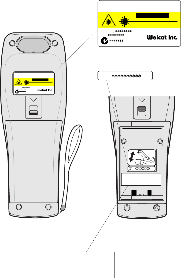
(INSIDE)
XIT-100-BW
Labels
CAUTION
Wirless
Hand-held Terminal
XIT-100-BW
FCC ID
IC
MADE IN JAPAN
LASER LIGHT DO NOT STARE INTO BEAM
650nmLASER 1.0mW MAX OUTPU
CLASS II LASER PRODUCT
CAUTION
Wirless
Hand-held Terminal XIT-100-BW
FCC ID
IC
MADE IN JAPAN
LASER LIGHT DO NOT STARE INTO BEAM
650nmLASER 1.0mW MAX OUTPU
CLASS II LASER PRODUCT
Product Label
SER
No.
Serial Label
This product complies with 21 CFR 1040.10.
MANUFACTURED:NOV.2005 Welcat Inc.
1-17-12 ShinYokohama,Kohoku-ku,Yokohama,
Kanagawa,JAPAN
FDA Label
This product complies with 21 CFR 1040.10.
MANUFACTURED:NOV.2005 Welcat Inc.
1-17-12 ShinYokohama,Kohoku-ku,Yokohama,
Kanagawa,JAPAN

viii
US and Canada Regulations
This device complies with Part 15 of FCC rules, Canada ICES-003 and RSS-Gen
rules.
Operation is subject to the following two conditions:
(1) this device may not cause harmful interference, and
(2) this device must accept any interference received, including interference that
may cause undesired operation.
Note:
This equipment has been tested and found to comply with the limits for a Class
A digital device, pursuant to Part 15 of the FCC Rules. These limits are de-
signed to provide reasonable protection against harmful interference when
the equipment is operated in a commercial environment. This equipment
generates, uses, and can radiate radio frequency energy and, if not installed
and used on accordance with the instruction manual, may cause harmful in-
terference to radio communications. Operation of this equipment in a resi-
dential area is likely to cause harmful interference in which case the user will
be required to correct the interference at his own expense.
Note:
This Class A digital device apparatus complies with Canadian ICES-003.
Cet appareil numerique de la classe A est conforme a la norme NMB-003 du
Canada.
FCC Warning:
Changes or modifications not expressly approved by the manufacturer re-
sponsible for compliance could void the user's authority to operate the
equipment.

ix
FCC Radiation Exposure Statement
Caution:
The available scientific evidence does not show that any health problems are
associated with using low power wireless devices. There is no proof, however,
that these low power wireless devices are absolutely safe. Low power Wireless
devices emit low levels of radio frequency energy (RF) in the microwave range
while being used. Whereas high levels of RF can produce health effects (by
heating tissue), exposure to low-level RF that does not produce heating effects
causes no known adverse health effects. Many studies of low-level RF expo-
sures have not found any biological effects. Some studies have suggested that
some biological effects might occur, but such findings have not been con-
firmed by additional research. The XIT-100-BW has been tested and found to
comply with FCC radiation exposure limits set forth for an uncontrolled
equipment and meets the FCC radio frequency (RF) Exposure Guidelines in
Supplement C to OET65. The maximum SAR levels tested for the XIT-100-BW
has been show to be 0.6101 W/kg at Body.
Co-location:
This Hand-held Terminal (XIT-100-BW) must not be co-located or operated in
conjunction with any other antenna or transmitter.

x
Contents
Contents......................................................................................................................................x
Introduction ........................................................................................................................... xiii
Enclosed items ...................................................................................................................... xiii
Optional Extras ..................................................................................................................... xiii
Notational Information........................................................................................................ xiv
Manual Contents.................................................................................................................... xv
Chapter 1 Hardware 1-1
1-1 Part Names...............................................................................................................................................................1-2
1-2 Preparation before Use..............................................................................................................................1-4
1-2-1 Equipment Connections ..........................................................................................1-4
1-2-2 Additional Software ..................................................................................................1-5
1-3 Wireless Communications........................................................................................................................1-6
1-3-1 Preparations for Data Communication................................................................1-7
1-3-2 Data-Communication Method ...............................................................................1-8
1-4 Product Specifications............................................................................................................................ 1-10
1-5 Scanning Specifications......................................................................................................................... 1-13
1-6 Charging specification............................................................................................................................. 1-16
1-6-1 Charging the Battery Pack................................................................................... 1-16
1-6-2 Charging Method using Single Charger (QC-001)......................................... 1-16
1-6-3 Charging Method using Multi Charger (QC-002) .......................................... 1-18
1-7 Battery pack (HBC-51)............................................................................................................................ 1-20
1-7-1 Charging the Battery Pack................................................................................... 1-20
1-7-2 Installing and Removing a Battery .................................................................... 1-20
1-7-3 Replacing the Worn out Battery Pack .............................................................. 1-21
1-7-4 Cautions about Cleaning of Electrodes ............................................................ 1-21
1-7-5 Charging the Backup Battery.............................................................................. 1-21
1-8 Memory Backup Period (Battery for backup)............................................................... 1-22
1-9 Not use in long time................................................................................................................................... 1-24
1-10 Resume function ........................................................................................................................................ 1-25
1-11 Screen Output Characters.............................................................................................................. 1-26
Chapter 2 Software 2-1
2-1 XIT-100-BW Software ..................................................................................................................................2-2
2-1-1 Data Storage ...............................................................................................................2-2
2-2 System menu .........................................................................................................................................................2-4
Chapter 3 System menu 3-1
3-1 Introduction..............................................................................................................................................................3-2
3-2 Save the System Parameter..................................................................................................................3-2
3-2-1 Registry ........................................................................................................................3-2
3-3 Key Names and Functions.......................................................................................................................3-3
3-4 System Menu Operations.........................................................................................................................3-5
xi
3-5 Battery Level...........................................................................................................................................................3-8
3-6 Starting the System Menu......................................................................................................................3-9
3-6-1 How to Start the System menu..............................................................................3-9
3-6-2 Executing a DHCP Request ....................................................................................3-9
3-6-3 Starting State for Wireless LAN Operation ........................................................3-9
3-6-4 Executing Setup Wizard ....................................................................................... 3-10
3-6-5 WLAN Security Alert............................................................................................. 3-12
3-7 System Menu List ......................................................................................................................................... 3-13
3-8 System Setup Menu................................................................................................................................... 3-15
3-8-1 Setting the programs for Automatic Launch................................................... 3-15
3-8-2 Clock ......................................................................................................................... 3-16
3-8-3 Resume (resume function) ................................................................................... 3-17
3-8-4 Password .................................................................................................................. 3-18
3-8-5 Auto wake up.......................................................................................................... 3-20
3-8-6 Auto power off........................................................................................................ 3-21
3-9 WLAN Menu ........................................................................................................................................................ 3-22
3-9-1 SSID ........................................................................................................................... 3-22
3-9-2 Roaming level ......................................................................................................... 3-23
3-9-3 Doze mode............................................................................................................... 3-23
3-9-4 Security..................................................................................................................... 3-24
3-9-5 Advanced ................................................................................................................. 3-31
3-9-6 MAC address ........................................................................................................... 3-32
3-10 Network Menu............................................................................................................................................... 3-33
3-10-1 TCP/IP .................................................................................................................... 3-33
3-10-2 DHCP ...................................................................................................................... 3-34
3-10-3 FTP .......................................................................................................................... 3-36
3-10-4 DNS ......................................................................................................................... 3-39
3-10-5 SNMP...................................................................................................................... 3-40
3-11 Receiving Menu............................................................................................................................................ 3-44
3-12 File Menu............................................................................................................................................................. 3-47
3-13 ID Menu................................................................................................................................................................. 3-55
3-14 Device Menu.................................................................................................................................................... 3-56
3-14-1 Barcode .................................................................................................................. 3-56
3-14-2 Key .......................................................................................................................... 3-61
3-14-3 Bluetooth .............................................................................................................. 3-61
3-14-4 Display .................................................................................................................. 3-68
3-14-5 Tone/Vibrator ..................................................................................................... 3-69
3-15 Manage Menu................................................................................................................................................ 3-74
3-15-1 Battery level .......................................................................................................... 3-74
3-15-2 System versions.................................................................................................... 3-75
3-15-3 Initialize.................................................................................................................. 3-75
3-15-4 Clone ..................................................................................................................... 3-77
3-15-5 Drive ..................................................................................................................... 3-80
3-15-6 Mothball................................................................................................................. 3-81
3-15-7 Wizard .................................................................................................................... 3-81
3-16 Test Menu.......................................................................................................................................................... 3-82
3-16-1 WLAN..................................................................................................................... 3-82
3-16-2 Bluetooth................................................................................................................ 3-86
3-16-3 Barcode .................................................................................................................. 3-87
3-16-4 Display.................................................................................................................... 3-89
3-16-5 Key .......................................................................................................................... 3-90

xii
Chapter FAQ (Frequently Asked Questions) 4-1
4-1 FAQ ...................................................................................................................................................................................4-2
Q: The power does not turn ON.......................................................................................4-2
Q: Nothing is displayed on the screen............................................................................4-2
Q: After not using for a while, the power is shut OFF. ..............................................4-2
Q: It cannot charge. .............................................................................................................4-2
Q: The System Menu does not start. ...............................................................................4-3
Q: How do I change the application, which starts when the power is turned ON?
..................................................................................................................................................4-3
Q: How do I start another application? .........................................................................4-3
Q: The Barcode is not scanned successfully. ................................................................4-3
Q: How do I check the free area of a drive?................................................................4-3
Q: I cannot perform wireless data communications. ..................................................4-4
Q: I cannot perform Bluetooth communication. ..........................................................4-5
Q: Can I use at the same time both WLAN and Bluetooth in the same environment
and on the same terminal?................................................................................................4-5
Q: "Writing Failed" was displayed during transmission or reception of a file. .....4-5
Q: "Time Out" was displayed during transmission or reception of a file. ..............4-5
Q: "Connection Failed" was displayed during transmission or reception of a file
. .................................................................................................................................................4-6
Q: I want to perform the setup of the terminal IP address etc. at a time from a
computer.................................................................................................................................4-6
Q: Starting an application or transmission/reception of a file cannot be performed.
..................................................................................................................................................4-6
Q: I suspect that the file is corrupt. .................................................................................4-6
Q: "System Error" was displayed and after pressing a key, the power turned OFF
. .................................................................................................................................................4-6
Appendix. A System Menu Factory Settings List A-1
Appendix. A-1 System menu Factory Settings............................................................................A-2
Appendix. B Sample Barcode B-1
Appendix .B-1 Sample Barcode....................................................................................................................B-2
Index I-1
Index............................................................................................................................................................................................ I- 2
xiii
Introduction
Thank you very much for purchasing a XIT-100-BW Wireless Hand-held Terminal.
This user's manual explains about the hardware and the System program of the XIT-100-BW.
We hope the XIT-100-BW will improve efficiency of your business.
Enclosed items
・ XIT-100-BW ................................................................................... 1
・ Battery pack(HBC-51) .................................................................... 1
・ Hand Strap....................................................................................... 1
・ Manual CD-ROM(GID-001)........................................................... *
* Attached in exclusive package.
Optional Extras
・ Dust protection cover(DC-001)
・ Anti-shock cover(DC-002)
・ Access point(AP-4131)
・ Single Charger(QC-001)
・ Multi Charger(QC-002)
・ BluePorter(WLF-001) - Bluetooth file transferring utility.
・ WebGlider-X(WBG-001) - Integrated middleware package for web applications.
・ Handy 5250(HTN-5250A) - 5250 Emulator for handy terminals.

xiv
Notational Information
Indicates a note you can refer to.
Indicates a caution.
"XIT-100-BW" "Terminal" Wireless LAN Terminal, Wireless Hand-held Terminal XIT-100-BW.
Access point
The wireless communication interface to allow data to be sent between
the XIT-100-BW and a PC connected to an Ethernet communicating
via TCP/IP. Please use our recommended equipment based on the
IEEE802.11b WLAN standard.
WLAN Wireless LAN
System Program The OS stored in the XIT-100-BW.
System Menu A function of the system program.
WebGlider-X browser The browser operates as an application of the terminal when web based
system is configured by using "WebGlider-X".
WebGlider-X "WebGlider-X" is an integrated middleware package for web applica-
tions (WBG-001). Please purchase separately if needed.
BluePorter
Utility software for executing file Transfer using Bluetooth communi-
cation between the PC and the terminal. Please purchase separately if
needed.
F Drive
The storage area for storing application, database, and master files. etc.
The application data downloaded from the host computer will be stored
in F drive.
S Drive Used for the storage area to store a temporary file during the applica-
tion is running.
Battery pack "HBC-51"
Backup battery The battery to perform a temporary saving the built in clock data and
files when the battery pack is removed or the power becomes short.
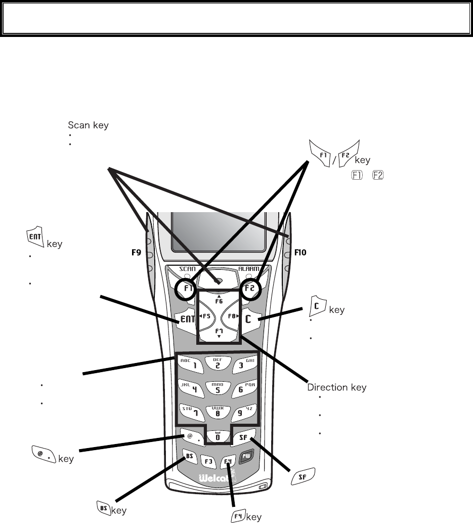
Scan key Used when scanning a barcode.
Local device Bluetooth device during operation is running. When the XIT-100-BW
is in operation, "Local device" means the XIT-100-BW.
Remote device Bluetooth device to which the local device is connected.
Default device
The Bluetooth device setup as default among the registered Remote
device list in the System Menu. In the System Menu always this default
device is connected to.
xv
Manual Contents
●Chapter 1 Hardware
Explains the standard handling, specifications and operation methods of the XIT-100-BW.
●Chapter 2 Software
Explains an outline of the software installed, and related to the XIT-100-BW.
●Chapter 3 System menu
Explains the System Menu setup and Operation Method.
●Chapter 4 FAQ (Frequently Asked Questions)
Questions and troubles frequently asked, and the items required for resolving them, refer-
ence pages of this manual are also commented.
●Appendix. A System Menu Factory Settings List
●Appendix. B Sample Barcode
●Index

Chapter 1
1 Hardware
Chapter 1 Hardware
1-2
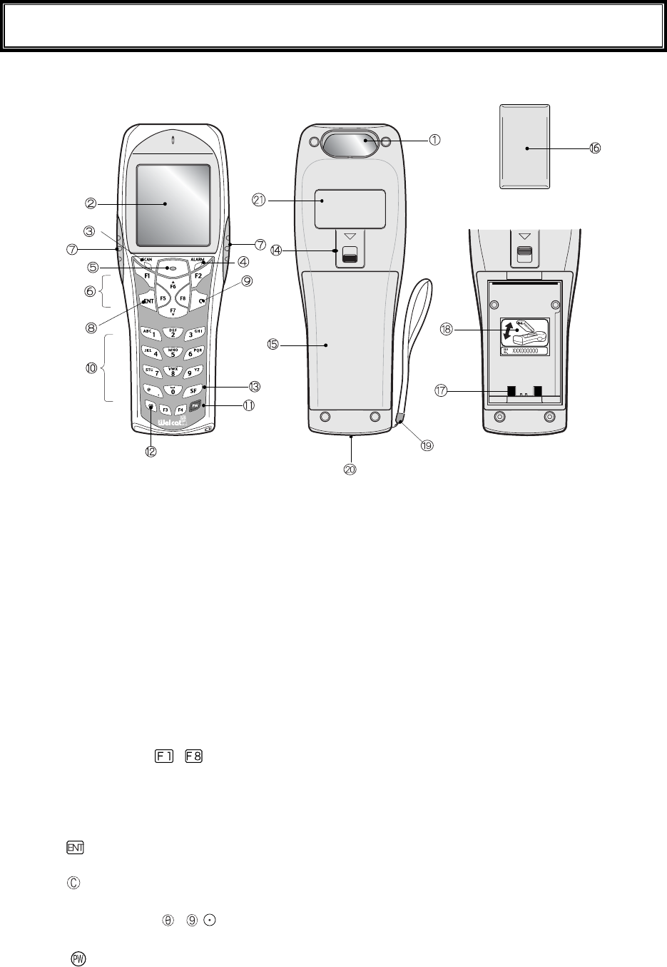
1-1 Part Names
(Inside the cover)
1. Barcode window
The opening from where the Barcode is read. As the laser light is irradiated, be sure NOT to look into
the window.
2. LCD (Liquid Crystal Display)
Data, characters and images are displayed on the LCD.
3. SCAN LED (LED Indicator)
If a barcode is read correctly, the light will turn green.
While the battery is being charged, the light will turn ON red. When the battery charging is completed,
it will turn ON green.
4. ALARM LED
Shows the status of Wireless Communications. Shows the status of wireless communication between
the access point and the status of EAP authentication. (P.1-12).
5. Scan Key
Press this key to read a Barcode.
6. Function Keys( to )
Used for changing functions and cursor operation.
7. F9 key, F10 key
Used for changing functions and cursor operation. Leftward by F9 key, Rightward by F10 key, when
using this key to scan a barcode, support by the software is required.
8. key (Enter Key)
Press this key to confirm and to execute the entered data or operation.
9. key (Cancellation Key)
Used to return to the previous screen, or deleted all the characters entered.
10. Numeric Keys ( to ,)
Used to input assigned numeric, characters, or, select the corresponding item in the Menu.
11. key (Power Switch)

1-1 Part Names
1-3
12. key (back space key)
Deletes the last character entered.
13. key (Shift key).
Used to switch to the character input mode, or special functions can be accessed by pressing this key
together with other keys.
14. Battery Cover Lock Lever
Move the lever to the direction of an arrow to lock. Be sure to keep it locked when using it.
15. Battery Cover
Always attach the battery cover while in use.
16. Battery Pack
After purchasing, be sure to charge the battery pack before you use. Be careful not to have the Charg-
ing terminal jack attached with dust or dirt. When dust or dirt is attached, remove it with a swab etc.
17. Charging jack
Be careful not to have the Charging terminal jack attached with dust or dirt. When dust or dirt is at-
tached, remove it with a swab etc.
18. Serial number seal
The seal is attached that carries serial number and a description about the direction to which re-
move/install the battery pack.
19. Hand Strap
20. Speaker Hole
21. Product plate
Product name, manufacturer and the laser alarm etc. are described.
Chapter 1 Hardware
1-4
1-2 Preparation before Use
Please carry out following preparations before using the XIT-100-BW
● Battery Pack HBC-51
The battery pack is required in order to use the XIT-100-BW. The battery pack should be charged be-
fore use, attached correctly and locked with the battery cover.
● Isn't the barcode window dirty?
If the barcode window is dirty, a barcode cannot be scanned correctly. When dirty, please wipe lightly
with a soft cloth etc.
● Isn't charging terminal dirty?
If the charging terminal is covered with dust or dirt, charging error or failure may occur. When dirty,
please remove the dust or dirt by using a swab etc.
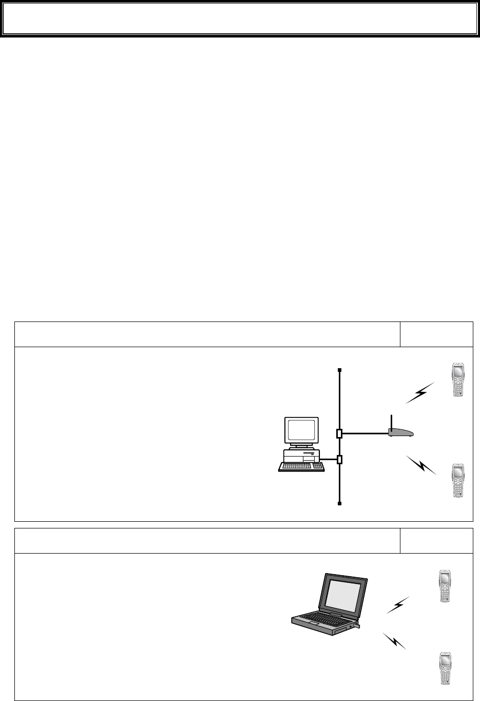
1-2-1 Equipment Connections
Data entered can be transmitted from the XIT-100-BW to a host computer or the XIT-100-BW can receive data
from a host computer.
The following are the Methods for connecting to a host computer. Preparations required depend on the applica-
tion environment.
In the case of WLAN communication P.1-8
The XIT-100-BW communicates via wireless LAN com-
munication to a host computer through an access point,
which is connected to the Ethernet LAN.
■Purchased Separately
Access Point (our recommended product)
Ethernet cables, HUB
For details about setting up a wireless network, refer to the
Access point Manual and the document.
In the case of Bluetooth communication P.1-9
The XIT-100-BW communicates via Bluetooth communi-
cation to a host computer through USB adapter, which is
connected to the USB port of the host computer.
■Purchased Separately
Transfer Utility "BluePorter" (Bluetooth USB adapter is in-
cluded.)
Computer

1-2 Preparation before Use
1-5
1-2-2 Additional Software
In the case where you want to create a system for data communication between the XIT-100-BW and a host
computer or build a system using theXIT-100-BW browser, the following software is required.
For details of the System configuration, please refer to the online Manual attached to respective software.
Software name Preparation/Use
Web based inte-
grated middleware
package
WebGlider-X
The WebGlider-X software is required when building a Web based wireless
system using the WebGlider-X Browser.
Please install the "WebGlider-X" package on a computer and setup the com-
munication environment, before performing data communication between the
computer and the "WebGlider-X" browser.
5250 Emulator for
handy terminal
Handy5250
The Handy 5250 software is required when creating a system to connect to an
AS/400 host via the 5250 emulation environment. Please purchase separately
if needed.
Before using, install the Handy 5250 setup utility, which will allow the setup
of the communication environment.
Transfer utility
Blue Porter
The Blue Porter is utility software to perform File Transfer for Bluetooth
communication. Please purchase separately if needed.
Before using, installing the driver software and the Bluetooth USB adapter
setups are required.
Chapter 1 Hardware
1-6
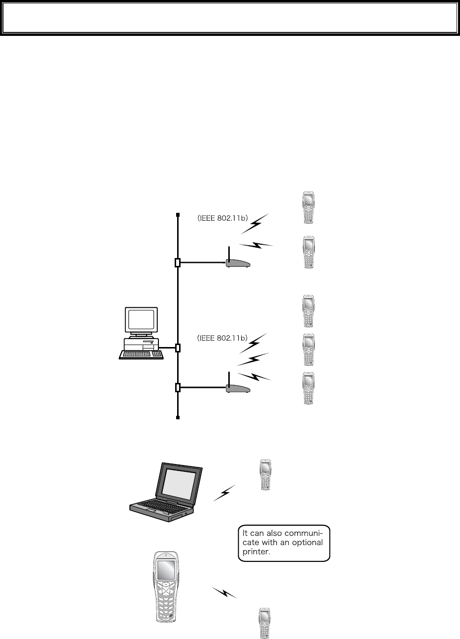
1-3 Wireless Communications
■Wireless function of the XIT-100-BW
The XIT-100-BW is a handy terminal network system incorporating a wireless communication system. The Bar-
code terminal is small, lightweight and excels in portability. It is also suitable for moving around the work place,
operating remotely from the computer while collecting Barcode data.
The XIT-100-BW 's wireless communication system is based on WLAN and Bluetooth methods. WLAN con-
forms to the WLAN standard, IEEE802.11b. The maximum possible wireless transmission speed is approxi-
mately 11Mbps, enabling the indoor wireless communication up to 75m distance. Bluetooth conforms to the
Bluetooth Specification ver1.1, enabling up to 10m communications. Transmission and reception of scanned
Barcode data or files can be performed in real time through the wireless network.
10/100
BASE-T
10/100
BASE-T
XIT-100-BW
XIT-100-BW
Access
Point
Access
Point
Wireless Network
Wireless Network
Computer
Network example (WLAN communication)
Computer
XIT-100-BW
Network example (Bluetooth communication)
1-3 Wireless Communications
1-7
■WLAN Communications
The wireless communication system is based on the IEEE802.11b standard, which is generally used in
Wireless Local Area Networks (WLAN). In almost all cases, wireless communication can be per-
formed if the access point used is based on the IEEE802.11b standard, however, please use our rec-
ommended product to perform a stable communication.
As for this product, only the infrastructure mode is supported. It does
not support ad-hoc mode.
■The role of an access point
An access point provides a wireless service area to a terminal (XIT-100-BW) and acts as a local
bridge, which performs packet transmission between the cabled LAN and wireless network.
Each terminal has a unique IP address, which allows direct Ethernet LAN connection through an ac-
cess point. This allows TCP/IP communication between the computer and the terminal.
Please use our recommended access points. For information on
manufactures and part numbers of the recommended access points,
refer to our catalog or contact our sales department.
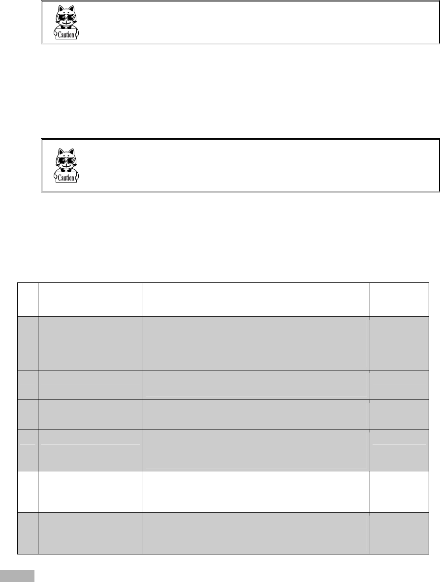
1-3-1 Preparations for Data Communication
For data communication between a computer and the XIT-100-BW, perform the following setup.
■WLAN communications
Item Description Reference
page
1. SSID Setup Set the SSID (or ESSID) of the XIT-100-BW to the
same as that of the access point. XIT-100-BW includes
an AP search function that will acquire and set up the
SSID of an available access point.
P.3-22
2. Security Setup Make the security settings to the same as the access
point.
P.3-24
3. TCP/IP Setup Set the TCP/IP address to allow communication with a
computer via the Ethernet LAN.
P.3-33
4. FTP Setup Make the FTP settings to allow wireless file transfer.
The FTP settings corresponds to the "WebGlider -X"
FTP server or general FTP server settings.
P.3-36
5. DHCP Setup Make the DHCP settings when using the DHCP client
function. This corresponds to the "WebGlider-X"
DHCP server.
P.3-34
6. DNS setting Make the DNS settings in the case where the DNS is
used for name resolution. Whether or not the DNS is
used depends on the application.
P.3-39
Items mean:
Using the DHCP client function on the computer side (P.3-34), all configurations are performed at the same time.
When you use the DHCP client function, "WebGlider-X " is required.
Chapter 1 Hardware
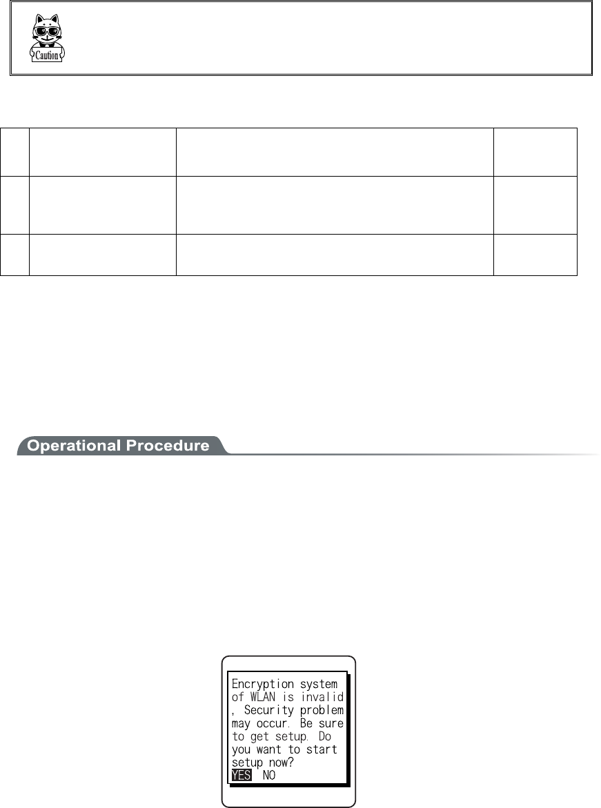
1-8
Since setting the "1. SSID Setup" and "2. Security Setup" using the DHCP
client function creates a security weak point, please do not use this
function whenever possible.
■Bluetooth communication
Item Description Reference
pages
1. Terminal ID setup ID number for Identification to each XIT-100-BW.
"BluePorter" and "WebGlider-X" identifies the terminal
using this ID.
P.3-55
2. Bluetooth device setup The setup of registrations to connect required for com-
munication, and Security etc.
P.3-61
1-3-2 Data-Communication Method
Once the equipment has been setup, data communication can be performed using the following procedures.
■In the case of WLAN communications
The procedure for performing WLAN communications is as follows.
1. Connect the access point to the Ethernet LAN, then setup the access point so that it can communi-
cate with a host computer.
At this point, be sure to perform Security setup.
2. In order to enable the Security setup of 1. , Restart the access point. (Some access points do not re-
quire restarting.)
3. Turn ON the XIT-100-BW and setup the WLAN and TCP/IP from the System Menu. At this point,
be sure to perform Security setup.
When the XIT-100-BW is started up without Security setup, the warning screen "NO WLAN Secu-
rity " is displayed.
Though it is possible to make this warning screen being not displayed, this is not recommended for
Security reason. Please set this screen if there is no special reason for not displaying it.
4. From System menu, set up TCP/IP. (P.3-33)
5. When setup is complete, first perform the Ping test toward the IP address of the access point, then
toward the IP address of the computer.

1-3 Wireless Communications
1-9
6. Setup FTP to transmit and receive a file.
・See P.3-51 for transmitting a file to a host computer from the XIT-100-BW.
・See P.3-44 for receiving a file from a host computer to the XIT-100-BW.
In the case using the DHCP function (P.3-34), "WebGlider-X" is required
separately.
■In the case of Bluetooth communication
The procedure to perform Bluetooth communication is as follows.
1. Starting up the host computer in which "BluePorter" is installed.
2. Connect the Bluetooth USB adapter to the USB port of the computer.
3. Starting up the "BluePorter", and perform the setup required for transmission or reception of files.
4. Turn ON the XIT-100-BW, perform setup for connection and so on.
5. Perform transmission or reception file.
・See P.3-51 for transmitting a file to a host computer from the XIT-100-BW.
・See P.3-44 for receiving a file from a host computer to the XIT-100-BW.

Chapter 1 Hardware
1-10
1-4 Product Specifications
CPU 32 bit RISC CPU
OS μITRON
16MB(including12MB for file area) ROM
Download file has 6MB max .In case the extension is "wav"
or "out", the download file has 5MB max.
Memory
RAM 16MB(including 6MB for file area)
Codes scanned NW-7, CODE39, JAN-13/8(add-on: enabled), UPC-A/E, In-
dustrial 2of5, ITF, CODE93, CODE128, EAN128, RSS-14
(Stack: enabled), RSS Limited, RSS Expanded*1
Number digits scanned MAX 74 digits (data digits)
Scanning width MAX 360mm
Light source Red light semiconductor laser
Laser class Class2 (JIS C 6802)
MAX output 1mW
Wavelength 650±10nm
Scanning speed 100scanning/ seconds
PCS 0.45 or more (reflectance space and margin: 70% or more)
Scanner
Resolution 0.127mm
SCAN LED Green / Red / Orange LED
ALARM LED Orange (which illuminates when out of range)
Display element FSTN dot matrix
Display size dots 132(W)×128(H)
Display Characters (Kanji) 10 chracters×10 lines (12dot font)
8 chracters×8 lines (16dot font)
Display Characters
(Single-byte characters)
20 chracters×10 lines (12dot font)
16 chracters×8 lines (16dot font)
Display area 38(W)×44(H) mm
Display Characters JIS level-1 kanji set, JIS level-2 kanji set, ANK, Symbols,
external characters. (Wide, tall and quad characters are en-
abled)
Contrast adjustment 8 levels
LCD
Backlight White LED (Luminosity adjustable)
Speaker Beep sound, audio, play via speaker.
At the time of scanning, various kinds of Error (can be speci-
fied by the user)
Vibrator Vibrated at the time of scanning, various kinds of Error (can
be specified by the user)
Key Input part Keys 27
Size 58(W)×162(D)×40(H) mm
Grip part45 (W)×26(H) mm
Weight Approximately 203g(battery pack included)
Cradle charging function Enabled (However the environment during charging con-
forms to charger's temperature specification)

1-4 Product Specifications
1-11
Main Battery Lithium-ion battery
Power
Backup Battery Lithium-ion battery (Maintenance free)
Working temperature -5 to 50°C
Working humidity 20 to 80% (non condensing)
Storage temperature -10 to 60°C
Storage humidity 10 to 90% (non condensing)
Drip-proof / Dust-proof IEC IP54
Drop impact proof 1.5m (onto concrete)*2
Operating
environment
Illumination conditions Artificial light up to 4,000lx
Sunlight up to 80,000lx
Continuous operation time Approximately 20 hours
Setup conditions: scan once in 20 seconds WLAN transmis-
sion or reception
Clock function Year (4 digits) Month/Date/Hour/Minute/Second
With automatic leap year compensation, With timer function
Specification Bluetooth Specification Ver1.1
Communication
Method
Spread spectrum (frequency hopping)
Frequency 2.4GHz band
Communication rate MAX 921.6kbps
Transmission power
class
Class2
Antenna Built in the body
Blue-
tooth
Communication dis-
tance
MAX 10m
Standards IEEE802.11b
Communication
Method
Spread spectrum (direct sequence)
Frequency 2.4GHz band
Antenna power out-
put
Less than 10mW/MHz
Transmission rate 11/5.5/2/1 Mbps (Switched automatically/fixed)
Number of channels 11
Security SSID, WEP (40/128), PSK-TKIP, IEEE802.1X
Antenna Built in the body
Wireless part
WLAN
Transmission range Indoors:MAX 75m, outdoors:MAX 200m
Management function SNMP agent
Support MIB MIB-II (RFC1213), Welcat Enterprise MIB
*1 a part of the specification RSS Expanded Stacked is not supported. About details please contact our sales de-
partment.
*2 test value, not guaranteed value.

Chapter 1 Hardware
1-12
■Display of ALARM LED during wireless communications
The state and meaning of the alarm LED during wireless communications are as follows.
LED state Meaning
OFF Communication with an access point is possible. Or no commu-
nication is currently taking place.
Blinking Continuous blinking during EAP authentication (P.3-28)
ON Communication with an access point has been attempted but syn-
chronization with the access point cannot be achieved. When the
barcode scanner goes out of sync with the access point, the LED
will turn ON.
■SCAN LED Display during terminal charging
SCAN LED status and Meaning during terminal charging is as follows.
LED status Meaning
Red ON Performing terminal charging.
Green ON Charging terminal has normally completed.
OFF During terminal charging, an Error occurred.
1-5 Scanning Specifications
1-13
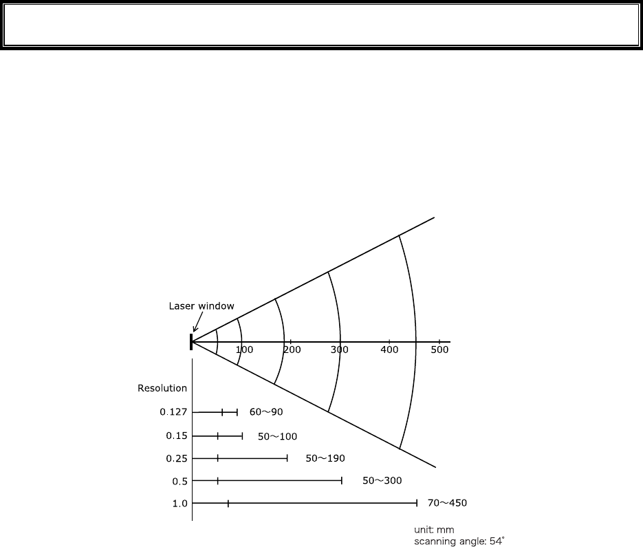
1-5 Scanning Specifications
■Laser light irradiation angle
The angle of the laser light irradiated from the XIT-100-BW is 54 degrees.
■Scanning Depth
The range across which a Barcode can be scanned is called a "scanning depth."
The scanning depth for the XIT-100-BW is as shown in the figure below.
Chapter 1 Hardware
1-14
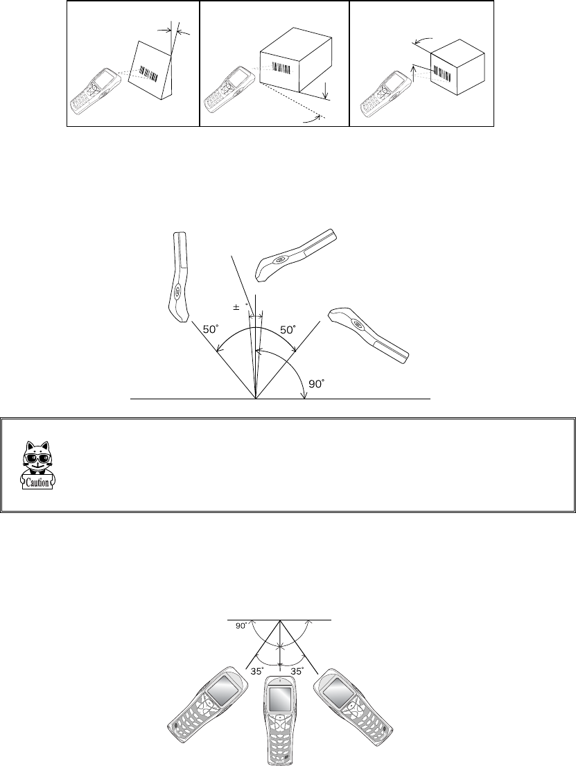
■Inclination of a Barcode and the angle with which it can be read
The following are the three kinds of a Barcode inclination
SKEW PITCH TILT
TILT
PITCH
SKEW
●Skew
Scanning is possible up t o 50°perpendicular to the upper and lower sides of a Barcode.
8
Dead Zone
The range of ±8°around a vertical line from the front face of a Barcode
is the "Dead Zone" caused by the specular reflection; scanning may
become poor within this range. Change the angle if you cannot read the
Barcode and scan it again.
●Pitch
Scanning is possible up to 35° perpendicular to the right and left of a Barcode.
1-5 Scanning Specifications
1-15
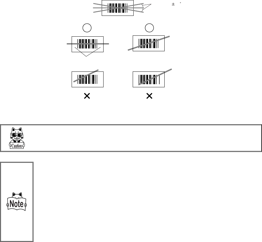
●Tilt
The Tilt is the angle with which the laser light irradiates the Barcode.
Tilt angle 20
Margin
The laser light should always cross the whole label. Make sure it also
irradiates the unfilled space (margin) to the right and left of the Barcode.
Measurement Condition is as follows.
・ 110mm from the head of the Laser scanner module.
・ Used label
At the time of measurement of pitch angle, skew angle, dead zone:
PCS=0.9, Resolution=0.25mm, 9 digits Code39, Narrow/Wide ra-
tio=1:2.5, margin=10mm
At the time of measurement of tilt angle:PCS=0.9, Resolution=0.26mm,
13 digits JAN, margin=10mm
Chapter 1 Hardware
1-16
1-6 Charging specification
1-6-1 Charging the Battery Pack
XIT-100-BW allows charging with a battery pack installed on the terminal by using dedicated charger
(QC-001/QC-002). Though the operation can be performed in this status, but be sure to avoid the key operation
lest it may fall or cause poor contact with the charging terminal.
1-6-2 Charging Method using Single Charger (QC-001)
When the XIT-100-BW and the battery pack are set at the same time, the XIT-100-BW charging has a priority.
After the XIT-100-BW charging completed, the battery pack charging starts.
The chargers can be connected by using the joint enclosed in the Single Charger (QC-001). (Limited to single
Charger). However carrying them as connected gives a large load on the joint fixed part, take care in handling.
When more than four chargers are connected, please use the Multi Charger (QC-002).
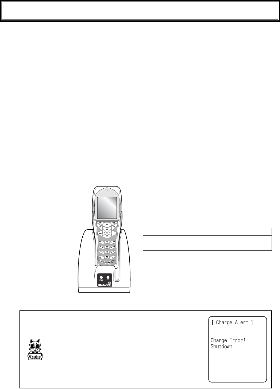
■Charging with the battery pack attached to the XIT-100-BW
During charging, the SCAN LED on the XIT-100-BW will turn ON red, when charging completed
turn ON green. Charging time is approximately 2.5 hours.
Take notes to the direction of the XIT-100-BW when set it on the charger.
Place the XIT-100-BW
in the charger as shown
below.
During charging SCAN LED red turn ON,
Charging complete SCAN LED green turn ON,
Charging Error SCAN LED turn OFF,
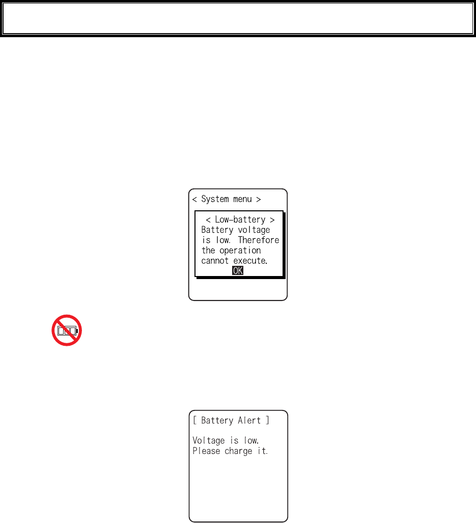
In case an error occurred during charging in the
state of running on, the screen on the right will be
displayed for 5 seconds, and then the power will
turn OFF.
1-6 Charging specification
1-17
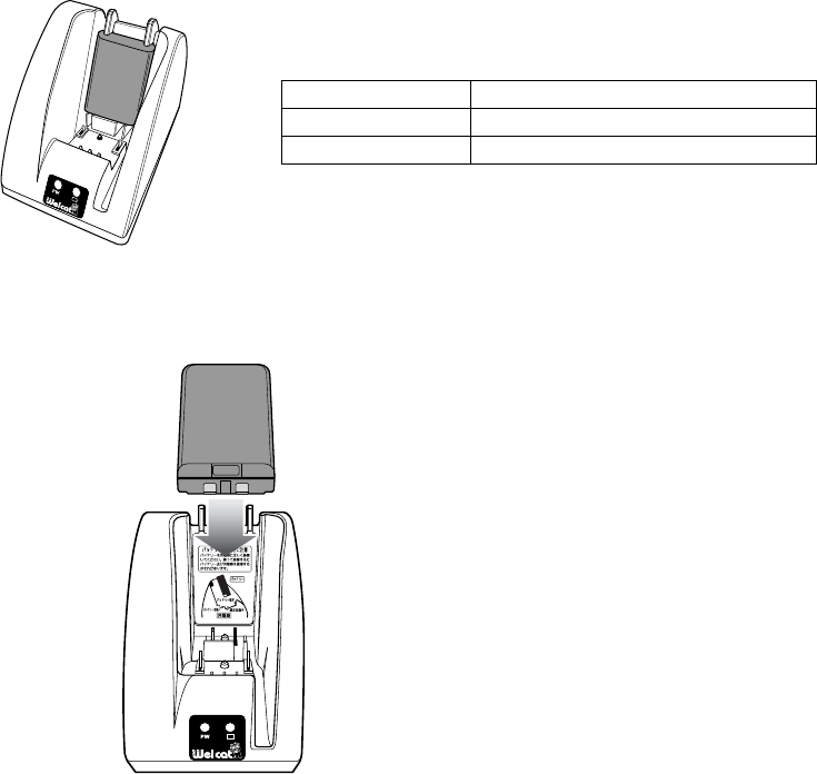
■Charging the Battery Pack alone
During charging, the Battery charging LED in the upper part of battery mark on the front of the
charger turns ON red, while charging has completed it turns ON green. Charging will be completed in
approximately 2.5 hours.
During Charging Battery charging LED red turn ON
Charging complete Battery charging LED green turn ON
Charging Error Battery charging LED turn OFF,
Please take care for the direction of the battery pack when you set it on the charger.
Place the battery pack in
the charger, as it should
turn a label side to the back,
and should set a electrodes
downward.
Chapter 1 Hardware
1-18
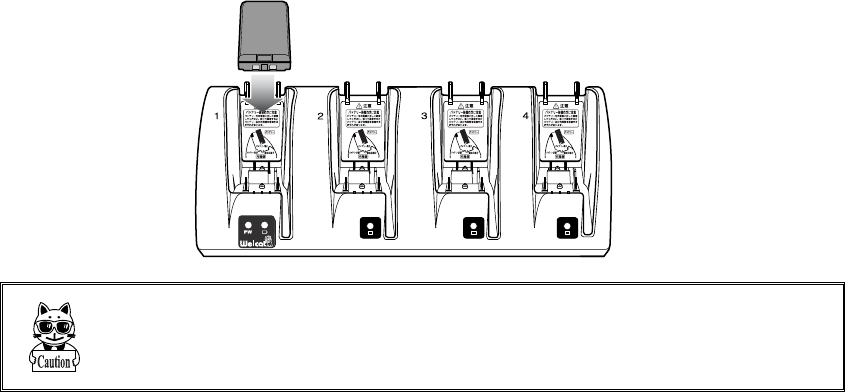
1-6-3 Charging Method using Multi Charger (QC-002)
The Multi Charger (QC-002) allows charging many batteries simultaneously. In the XIT-100-BW and the battery
pack which are set in the same number as that of the Multi Charger, the XIT-100-BW charging has the priority;
the battery pack charging starts automatically after the XIT-100-BW charging has completed.
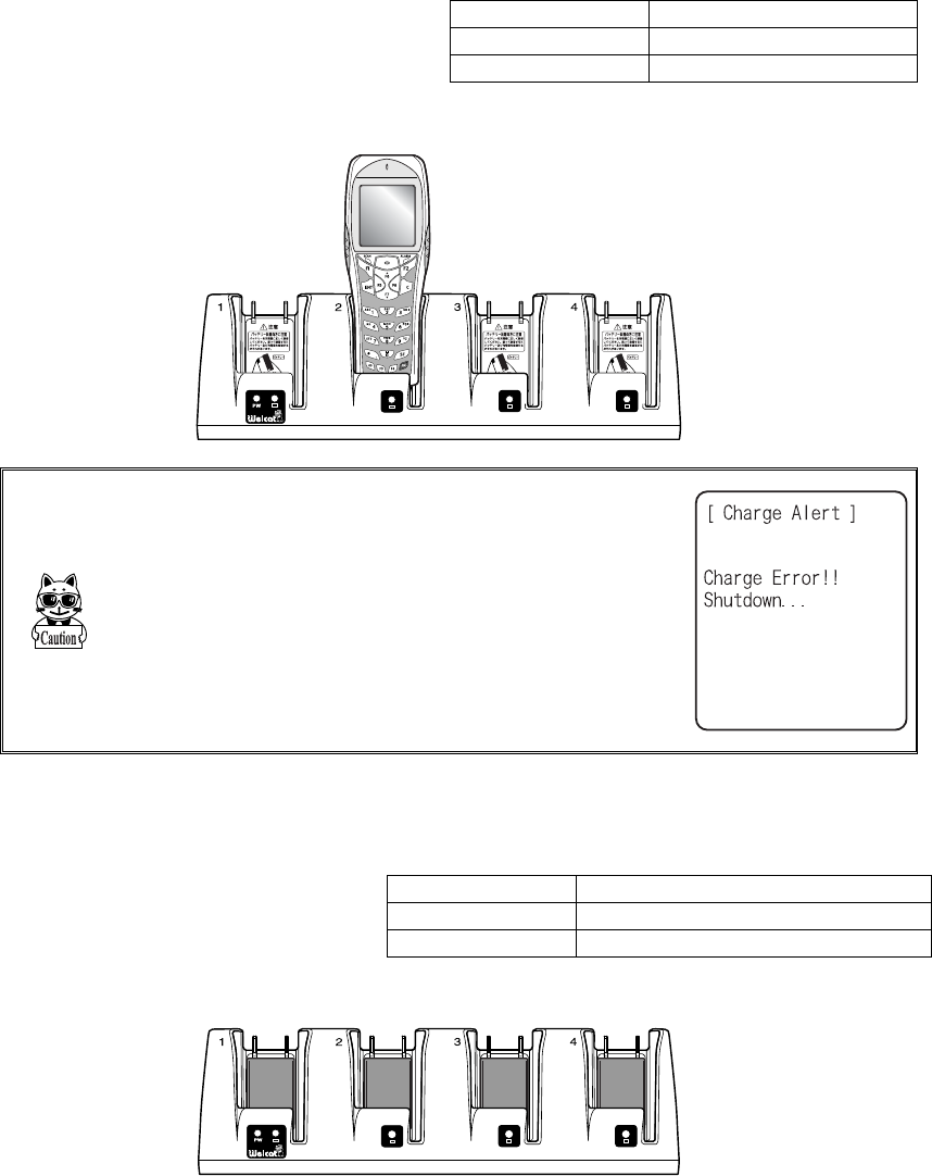
■Charging the battery pack attached to the terminal.
During charging the SCAN LED on the
XIT-100-BW terminal will turn ON red,
when charging completes turn ON green.
Charging time is approximately 2.5 hours.
Take notes to the direction of the
XIT-100-BW when set it on the charger.
During charging SCAN LED red turn ON
Charging complete SCAN LED green turn ON
Charging Error SCAN LED turn OFF,
Place the XIT-100-BW in
the charger as shown below.
When error occurred during charging in the state of
running on, the power will turn OFF displaying the
screen on the right for 5 seconds.
■Charging a battery pack alone
While charging, the LED on the up-
per part of the mark on each battery
turns ON red, and when charging
completes, it turns ON green.
Charging time is approximately 2.5
hours.
During charging Battery charging LED red turn ON
Charging complete Battery charging LED green turn ON
Charging Error Battery charging LED turn OFF,
When setting battery on the charger, please take notes to the direction of the battery pack.
1-6 Charging specification
1-19
Place the battery pack in the
charger, as it should turn a label
side to the back, and should set
a electrodes downward.
When charging Error occurred, charge it again. If the error occurs re-
peatedly, remove the battery and contact our sales department. Take care
not to use the battery that the error occurred.
Chapter 1 Hardware
1-20
1-7 Battery pack (HBC-51)
1-7-1 Charging the Battery Pack
Be sure to follow the precautions below when handling the battery pack.
・ After purchasing, be sure to fully charge the battery pack before using.
・ Be sure to shut off the power before removing the battery pack. If the battery pack is removed during
operation, the data file in the S drive may be corrupted.
・ Be sure not to touch the electrodes with your hand, and avoid dust on the electrodes. Otherwise this
may cause poor contact with the battery pack and the XIT-100-BW.
・ When dirty, wipe clean with a dry soft cloth.
・ When installing and removing the battery pack, use a desk or other appropriate surface as the working
table so that it cannot fall onto you feet.
・ Be sure to attach the battery cover and lock it before use.
1-7-2 Installing and Removing a Battery
A packing material to protect the water immersion is attached to the Battery cover. When installing the Battery
cover, please confirm if the dust or dirt NOT attached to the packing or the packing inserted correctly. If the dust
or dirt is attached, wipe it softly with dry clean cloth.
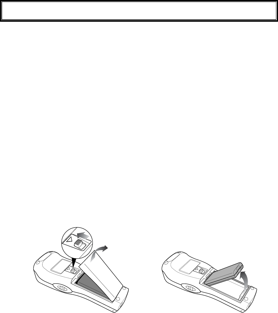
■Removing the Battery Pack
2.Remove the battery
cover.
1.Release the lock by
sliding up the lock
lever.
3.Take out the battery pack
from electrodes side.
1-7 Battery pack (HBC-51)
1-21
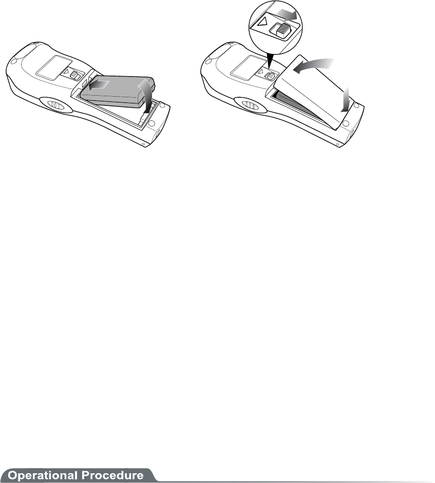
■Installing the Battery Pack
1.Insert the battery pack
in main body cushion
side first.
2.Attach the battery cover to
bottom side first, and lock
by sliding down the lock
lever.
1-7-3 Replacing the Worn out Battery Pack
A battery pack is an expendable item. Even if the battery pack is used correctly, it will deteriorate gradually in
the course of being charged and discharged repeatedly.
If the usage time is becoming shorter even after charging for the specified charging time, please replace the ex-
isting battery pack with a new one.
1-7-4 Cautions about Cleaning of Electrodes
When the operational time has become shorter or it is having trouble starting, poor contact between electrodes
because of dirt, may be the cause instead of a degrading battery. If this is the case, cleaning both the battery elec-
trodes and the main body electrodes will improve this condition.
●Methods for cleaning the electrodes
Please wipe the dirty electrodes with a clean dry soft cloth, a swab, etc. Never rub the electrodes with
an unclean cloth, fingers or a hard object. Wipe the electrodes lightly, especially the main body elec-
trodes, else they may get scratched or deformed.
1-7-5 Charging the Backup Battery
This section describes the Method for charging the backup battery.
1. Put the XIT-100-BW (with no battery pack installed) and one fully charged battery pack at a handy
place.
2. Install the XIT-100-BW with the battery pack. The charging process for the backup battery will
then be started. If the Backup Battery has completely been discharged, do not remove the battery
pack for at least two days after the start of the charging process.
Chapter 1 Hardware
1-22
1-8 Memory Backup Period (Battery for
backup)
XIT-100-BW has two drive areas to store the file: F drive (Non-volatile) and S drive (Volatile). The application
data download from host computer is stored in F drive, so the data won't be lost even if the battery pack has
worn out. (Refer "2-1-1 Data Storage" "■Information about the data storage (drive configuration)" See P.2-2).
■Memory Back Up by battery pack
Battery Battery pack
Use The operation by XIT-100-BW
Charging time Charging the battery by using a Dedicated charger, Approximately 2.5
hours to complete charging.
Backup Period The data storage period with a full charged battery pack attached is as fol-
lows.
・ The data in S drive and resume (suspended) information:
Approximately 25 days
Notes in Use When the battery pack is removed during operation, the data in the S drive
and resume information will be lost. When temporary storage is per-
formed, be sure to press the key to power off, and then remove the bat-
tery pack. Refer to "1-10 Resume function"(P.1-25) for resume function.
If such an operation as removing a battery pack each time the terminal is
not used (the memory back up by the back up battery is applied), the
backup period will get extremely shortened in approximately half a year.
In this case, the replacement of the backup battery is necessary (paid)
therefore please attach the battery pack except for changing the battery.

1-8 Memory Backup Period (Battery for backup)
1-23
■Memory Back up by backup battery
Battery Battery for Backup
Use The Clock data built in XIT-100-BW is kept. In addition, The data in the
S drive is saved only for a certain period while replacing batteries etc.
When resume function setup is enabled, the resume information is
stored.
Charging time Approximately 2 days after fully charged battery pack is attached to the
XIT-100-BW.
Backup period Data storage period after removing the battery after Normal termina-
tion*1 is as follows.
・ S drive data and resume information (when resume function is
enabled):Approximately 15 hours
・ Built in clock data:Approximately 6 months
Data storage period after terminating by Mothball Menu*2 is as follows.
・ Built in clock data:Approximately 1 Year
(with or without battery pack)
Notes in Use For details of prolonged storage of the terminal, please refer to"1-9 Not
use in long time" (P.1-24).
The data lost due to the worn out of the battery for back up will not be
restored. Be sure to save the data other than the temporary one in the F
drive.
*1 Normal termination:The termination method after pressing the key remove the battery pack.
*2 Termination by Mothball :The method to terminate to select mothball from the System menu.
The Memory backup time varies depending on the surrounding envi-
ronment. For example, backup time will be drastically reduced in tem-
perature below 0oC and over 40oC and more. It is recommended to use
the battery at room temperature.

Chapter 1 Hardware
1-24
1-9 Not use in long time
■Not use in long time (the terminal)
If you do not use the terminal for a long period (more than 6 months), it is recommended to setup the
terminal to Mothball, the power will soon turn off.
By Mothball setup, though the data in the S drive and resume information will disappear, the built in
clock data will be kept, thus saving the consumption of the battery. About setup method, refer to
"3-15-6 Mothball"(P.3-81) for the Setup method of Mothball.
■Not use in long time (the battery) for Battery
When you do not use the battery for an extended period of time, setup the terminal to Mothball and
removing the battery to keep it in a cool spot charged about 50%. When you do not use it for one
month or more, remove the battery pack and keep it at room temperature.
The battery may deteriorate rapidly by over discharging or under high temperature.
1-10 Resume function
1-25
1-10 Resume function
The XIT-100-BW supports resume function, from System menu, setup, the behavior of the power on by the
key. For setup method, see "3-8-3 Resume (resume function)"(P.3-17).
Resume function enabled After pressing key to turn off the XIT-100-BW and start up with
the key, the processing resumes what was executed immediately
before the power off.
Resume function disabled After pressing key to turn off the XIT-100-BW and start up with
the key, the processing always starts from the first stage.
Please be informed that when the battery pack is removed during the
operation of the terminal, the program will be executed from the begin-
ning regardless whether the resume function is enabled or disabled.
Please be informed that when the back up battery is consumed, the pro-
gram will be executed from the beginning regardless whether the Resume
function is enabled or disabled. With regard to charging the battery for
backup, please refer to "1-7-5 Charging the Backup Battery"(P.1-21).
Chapter 1 Hardware
1-26
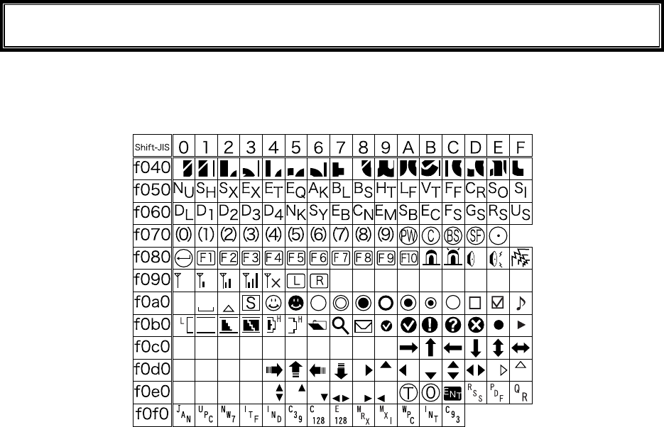
1-11 Screen Output Characters
■Welcat specific Double-byte characters
1-11 Screen Output Characters
1-27
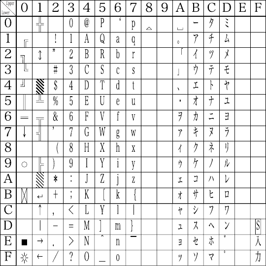
■Single-byte characters

Chapter 2
2 Software
Chapter 2 Software
2-2
2-1 XIT-100-BW Software
The XIT-100-BW Software consists of the following two types.
System program
Controls the basic operation of the XIT-100-BW. It is equiva-
lent to an OS (operating system) of a personal computer, and
is preinstalled in the XIT-100-BW. The System Menu, which
sets the basic parameters for operation and performs various
verifications, is a part of the system program.
Application program
Used for user operations processing. This program is mainly
used for scanning Barcodes, data transmission to a computer,
etc. If you purchase "WebGlider-X", you can easily combine
it with the WebGlider-X Browser to build a Web based sys-
tem. If you purchase "Handy5250", it allows you 5250 emu-
lation and configures the handy terminal system with high re-
liability of AS/400 host computer.
Refer to "Chapter 3 System Menu" (P.3-2) for detailed information about
the System Menu.
For information about "WebGlider-X," see the online manual included
with the product package.
2-1-1 Data Storage
■Information about the data storage (drive configuration)
The XIT-100-BW has two drives for storing data. The S Drive and the F Drive.
Drive Data Retention Use Maximum Capacity
F drive ●Non-volatile memory
The contents of this drive
will be retained after the
backup battery is dis-
charged.
Used to store all files, such
as application, the database
master files and normal data
files, etc.
64 files
S drive ●Volatile Memory
Once the battery pack is
suddenly removed during
operation or the backup
battery is discharged the
contents of the drive will
be lost.
S Drive Used to store tem-
porary files when an appli-
cation is running on.
64 files
When the F Drive receives a file, the S Drive receives the file first then moves it to the F Drive.
In case where the F Drive receives a file, confirm that there is enough storage space on both the S
Drive and F drive beforehand.
When receiving files if there is a file with identical name on the S drive, the old file will be erased.

2-1 XIT-100-BW Software
2-3
■File Naming
The file names used by the XIT-100-BW are subject to the following restrictions.
File name length A file name allowed to enter is up to 31byte long, including
extension.
Characters that
can be used.
Characters can be composed of as any combination of the fol-
lowing characters.
・ Alphabet(A to Z)
・ Numbers (0 to 9)
・ Symbols(!#%&'()@^_{}~.)
・ Single-byte space
Other restrictions A space, or, "."(Period) is prohibited to use at the head of the
file name.
■About extensions
The XIT-100-BW recognizes files through extensions.
".OUT" Recognizes as an application.
".WAV"
".MP3"
".SFL"
Recognizes as audio data.
Subject to format restrictions for the WAV file and MP3 file that
can be played on XIT-100-BW. (P.3-47)
SFL is a system original style text file. (P.3-47)
".BMP" Recognizes as a Bitmap image.
The bitmap file displayed on XIT-100-BW is subject to format
restrictions. (P.3-47)
■The files generated by the system and application
A part of the System program and application program of the XIT-100-BW create a temporary file
and a file to save the setup value. If these files could not be generated for such reasons that there are
too many files, or no space in the drive etc., each program fails to work normally.
System program generates a registry file in the F drive to save the Setup value of the System menu.
Four files are created in this case, however, this is a hidden file and not displayed in the System menu.
By using WebGlider-X browser following files are created in the S drive during HTTP communica-
tion.
Since a file with the same name is overwritten, be sure to use a different name than the following file
names.
・ HTTP.LOG
・ HTTPTEMP (with no extension)
・ HEADTEMP (with no extension)
When an application is programming, and SQLite Library is used, a temporary file will be created in
the S drive during database operation. The file name will be created randomly to avoid overlapping
with the existing file.


Chapter 3
3 System menu

Chapter 3 System menu
3-2
3-1 Introduction
The System menu is a part of the system program, which is preinstalled in the XIT-100-BW as one of the func-
tions that comprise the operating system. It also provides a platform for installing application programs and per-
forming environmental setup for the whole system.
This chapter describes how to set up the XIT-100-BW and perform various verification checks, with primary
focus on how to use the "System menu."
3-2 Save the System Parameter
3-2-1 Registry
The system parameters that are set up in the System menu are called "Registry".
In addition, as these registry files are not displayed in the System menu as these are hidden files. As the registry
is saved in the F drive, it will be not erased even though the back up battery is worn out.
Registry is classified into five categories as below.
User Registry General set up value. Most part of the items setup in the System
menu creates the User Registry.
Security Registry Security related setup value such as WEP key and SSID etc.
Unique Registry Setup value unique to the terminal such as IP address and terminal
ID, which generally does not overlap to the other terminals.
System Registry Using a unique setup value used by the XIT-100-BW.The execu-
tion of Setup or reference from the System menu is not enabled.
Device Registry This is the item such as Battery level or radio signal level that is to
refer the parameter that changes in real time during the operation
of the terminal. The setup value that belongs to this device registry
can only be referred to, but unable to setup.
The four registries except for Device registry are saved in an independent file respectively. For this reason there
are four files are always stored in the F drive of XIT-100-BW. As the registry is stored in the F drive, it will be
not erased even if the battery is disconnected.
The Device registry is not saved in a file, as it varies according to the operation status of the terminal.
Please refer to "Appendix. A-1 System menu Factory Settings"(P.A-2) with regards to what menu the setup
value belongs to.
The Clone (P.3-77) allows the other terminal to copy the registry and duplicate the terminal with the same setup
as that of the original.
By using "initialize" Menu (P.3-75), the registry will be erased, restoring the terminal to the status of Factory
Setup.
3-3 Key Names and Functions
3-3
3-3 Key Names and Functions
This Chapter explains about keys and functions used in the System menu.
In this Manual each key is described as follows.
key
Switches the character input mode.
Ten key
Used to return to the
previous menu.
Used to clear all the
characters entered.
Used to enter assigned
number and characters.
Used to select the corre-
sponding menu item.
Press this key to read a barcode.
In the system menu, F9 and F10 key
also have the same function as a scan
key.
Used to confirm an op-
eration or the Selected
menu item,
Used to confirm input-
ted data.
move the selected item When
entering character
move the cursor to the direction
shown by the arrow.
Change the upper-case/lower-
case of the entered character.
When or is displayed, the
corresponding key is pressed to
display the sub menu or exe-
cute assigned functions (special
features).
Turns on/off the back light
each time the key is pressed.
When the battery level is lower
than the regulated value, the
backlight does not turn on.
Delete an entered char-
acter.
Input Symbols and decimal
points.
Chapter 3 System menu
3-4
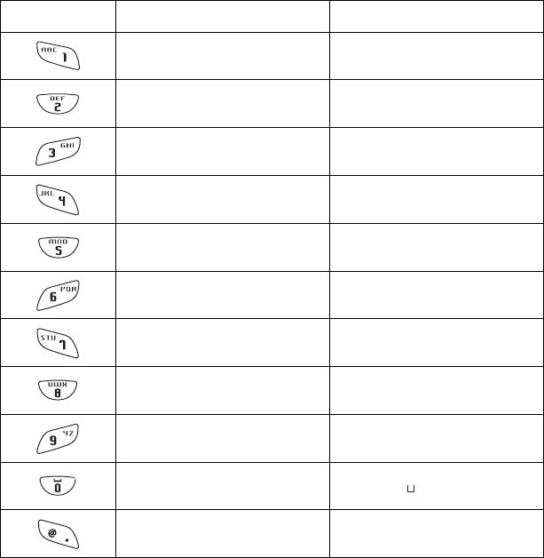
■Assigned key character list
Key Numeric input mode Alphabet input mode
1 ABC
2 D E F
3 G H I
4 J K L
5 MNO
6 P Q R
7 S T U
8 V W X
9 Y Z
0 (space)
・ $-+/%:#@&
3-4 System Menu Operations
3-5
3-4 System Menu Operations
Here explains the Standard Operation Method of the System menu.
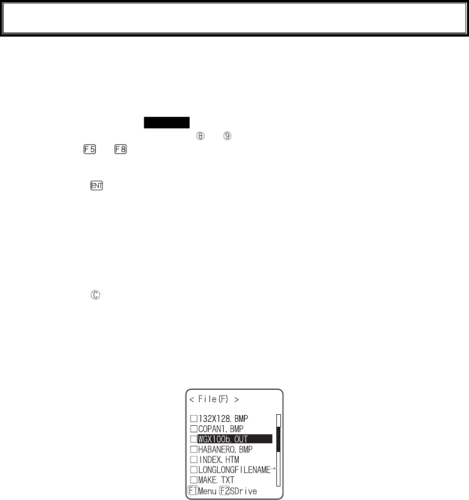
■Select the target item from the menu
●Selecting a Menu Item
Selected item becomes highlighted (colors reversed= selected).
Move the cursor either by pressing to key, which corresponds to the item, or, by using the di-
rection ( to ) key.
●confirm the selected item
Press the key, and, confirm the selected item.
The behavior after confirmation differs according to the item.
・ Execute the corresponding function
・ Show the decision [Yes] or [No] (check box)
・ Next Menu is displayed.
・ Sub menu is displayed.
●Cancel Selecting
Press the key, to return to the previous operation.
●Screen display
When the items in the Menu are not housed in a screen, the scroll bar for vertical direction is dis-
played on the right of the screen. In addition, when the item name exceeds 1 line, the tail of the item
name is displayed being converted in "→ "
■Input Barcode data
●Barcode Scanning
Press the scan key and irradiates the laser to scan a barcode.
The irradiation time of the laser and scanning behavior are set up with trigger mode. In addition, Bar-
code test menu is not subject to trigger mode.
●Barcode scanning condition
The Barcode that can be scanned in the data input mode is as follows.
NW-7, CODE39, JAN13/8, UPC-A/E, Industrial 2of5, ITF, CODE93, CODE128, RSS-14, RSS
Limited

Chapter 3 System menu
3-6
■Input by the key
●Switching the Character Input mode
XIT-100-BW allows inputting characters using numeric keys and key.
The character allowed to enter is Numeric, Alphabet (upper-case/lower-case) and Symbols, changing
input modes according to the character to enter.*1
・"Numeric input mode"
Numeric and decimal point are allowed to enter.
・"Alphabet input mode"
Alphabet (upper-case/lower-case) and Symbols are allowed to enter.
Each time the key is pressed, the input mode changes。*1
●Numeric input
Make the character input mode to numeric input mode( cursor: ■(rectangle)).
Press to key, and input corresponding numeric. Press the key, and input decimal point.
●Alphabet input
Make the character input mode to alphabet input mode( cursor:_(under bar)).
Press to key, and input the assigned alphabet.
When an assigned Alphabet on the same key is continuously entered, press the key to move the
cursor, and input the next alphabet.
Press the / key, and alphabet at the cursor position changes ;Upper-case character ⇔
Lower-case character.*2
●Input the symbol
Make the character input mode to alphabet input mode( cursor: _ (under bar)).
Press the key, or key, and input the assigned symbol.
When an assigned symbol on the same key is continuously entered, press the key to move the
cursor, and input the next symbol.
When the cursor is at the end of the entered data, press the key, and a space is inserted to the
right of the cursor.*2
●Confirm the entered data.
Press the key.
●Delete the character*3
Press the key, and delete the character at the cursor by 1 character.
Press the key, and delete all characters.
●Cancel the input
In such an item that deleting characters is not allowed (refer to *3), press the key, and stop the in-
put immediately. In such an item that deleting characters is allowed, after deleting all characters en-
tered and press the key.
●Others
When the input characters are filled over the field length, the cursor returns to the top.
*1 The item that the kind of characters allowed to enter is restricted ( example:terminal ID is nu-
meric only )cannot change the Input mode.
*2 The Characters allowed to enter may be restricted according to the item.
*3 In the item of which format to enter is fixed(example:IP address) the character cannot
be deleted. In this Manual the Input Format fixed items are shown with the icon in the
right.

3-4 System Menu Operations
3-7
■Other operations
●Returning to the previous menu.
Press the key.
●Check box operation
By applying or removing checks in the square box, making the item selected/not selected. Each time
the key is pressed, the status of Select /Not Select switches.
Each time the key is pressed ,[Yes]/[No] switches.
The check box is also applied when selecting many items at the same time.
●Radio buttun operation
The item the inside of the small circle is dotted shows that it is currently enabled.
Radio button is used to select one item from many items.
●Message box operation
When two buttons are displayed in the lower part of the box; [Yes]/[No] etc., press or, key, or
select the button by using the direction ( to ) key (Highlighted), and then press the key to
confirm. Press the key to select the right button.
In such a case with one button like "OK", press the key or key.
●Level meter operation.
Setup value adjustment by stages.
Move the slider Up and Down by / key. And then, press the key to confirm the level
value.
Press the key to cancel setup.
●Turning ON/ OFF the backlight.
Each time by pressing the key, the backlight turns ON/ OFF. However in case the battery level is
less than the regulated value, the backlight does not turn ON.
●Accessing to the Sub menu or function.
When or is displayed in the lower part of the screen, press the corresponding key to display
the Sub menu or execute the function.
●Modifying the indicator when operating
The indicator (buzzer/audio/vibrator/LED) that works when operating allows itself to be modified to
user's original setup. With regard to the modification Method, please refer to"■Indicator func-
tion"(P.3-69).
By modifying this setup users' are allowed to create their original indicator easily.
In addition, there are some operations that the indicator is not applied.
Chapter 3 System menu
3-8
3-5 Battery Level
When the battery level of the battery pack lowered, operation is restricted or the power may turn OFF.
●Checking the current battery level
From the System menu, select"8:Manage", and then "1:Battery level".
●Restricted operation when the battery level is low.
Some operations of the System menu are restricted, when the voltage level is less than the regulation
level (the level differs according to the operation) at the time of execution.
In this Manual, the operation that will be restricted is shown with the icon.
●Battery Alert
The Display below and the buzzer inform the user of the battery shortage.
Approximately after 5 seconds, the power is forcibly turned OFF.
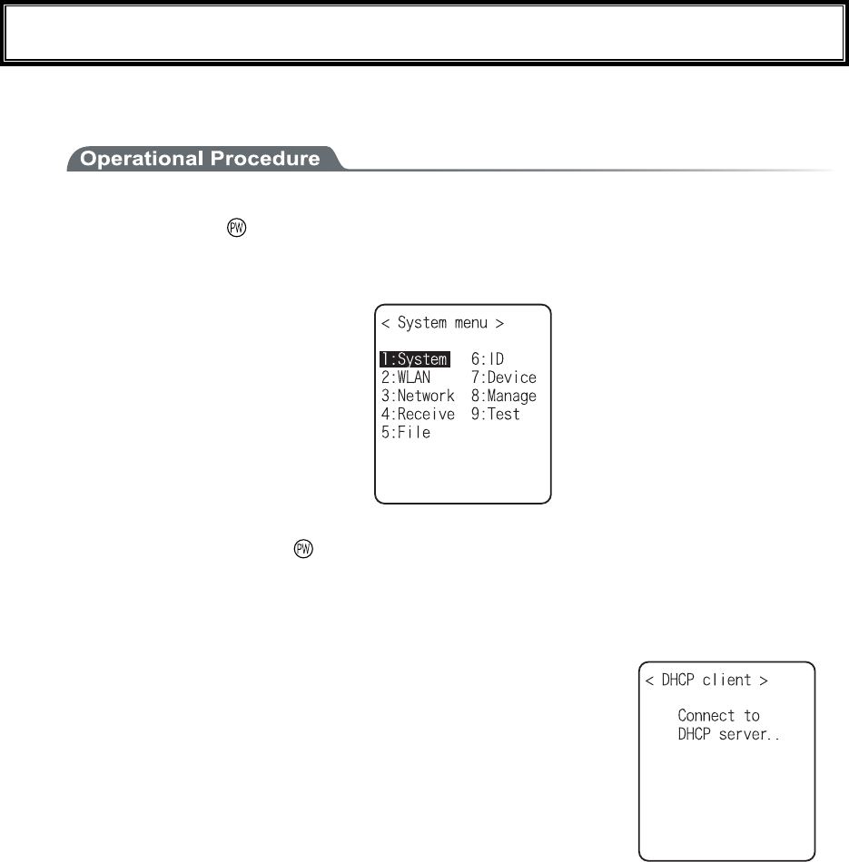
3-6 Starting the System Menu
3-9
3-6 Starting the System Menu
3-6-1 How to Start the System menu
1. Once the XIT-100-BW has been correctly installed with a battery pack and if the current state is
OFF, press the key for approximately 1 second. The power will turn ON and the System menu
will be started.
2. The System menu is displayed immediately after the opening screen.
If an application is set for " Auto execute" (P.3-15), hold down the scan key (excluding F9 and
F10), and then press the key to start the System menu.
3-6-2 Executing a DHCP Request
If the "■Startup type"(P3-35)is setup at[application boot], [System menu boot],
the DHCP request will be executed every time of booting.
If the system is in the state where wireless communications with an access point
is possible and if the DHCP server and FTP server of the "WebGlider-X " Net-
work Manager have been started, the various environmental setting values and
specified files will be downloaded to the XIT-100-BW and automatic setup will
be perform via the TCP/IP network.
After the DHCP request has been executed, the applications set for "Auto exe-
cute" if any, will start. (P.3-15)
3-6-3 Starting State for Wireless LAN Operation
Immediately after starting, the XIT-100-BW's wireless LAN communication unit is set to a resumed state. If the
wireless communications related menu is selected immediately after starting, the XIT-100-BW will be ready for
communication within 0.5 to 1 second.
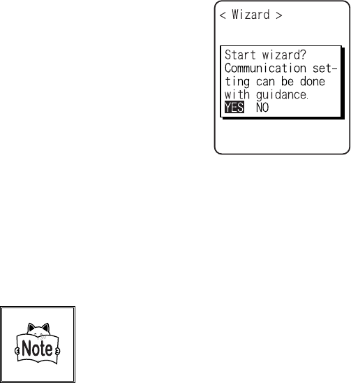
Chapter 3 System menu
3-10
3-6-4 Executing Setup Wizard
At the initial startup of the terminal, the setup wizard is executed to perform the minimum setup of the request
for communication between the terminal and the server.
Select either[Yes]or [No].
Select [Yes], then the wizard will be executed to perform the setup of WLAN and TCP/IP.
Select [No], then the System menu will start up.
When selecting [No] to skip the Setup Wizard, or, completing the setup to the last moment by executing Setup
Wizard, the Setup Wizard will not startup from next time and after.
Each item to be entered in the Setup Wizard can be set up each by each in
the System menu. In addition, Setup Wizard can be arbitrarily executed
from the System menu (P.3-81).
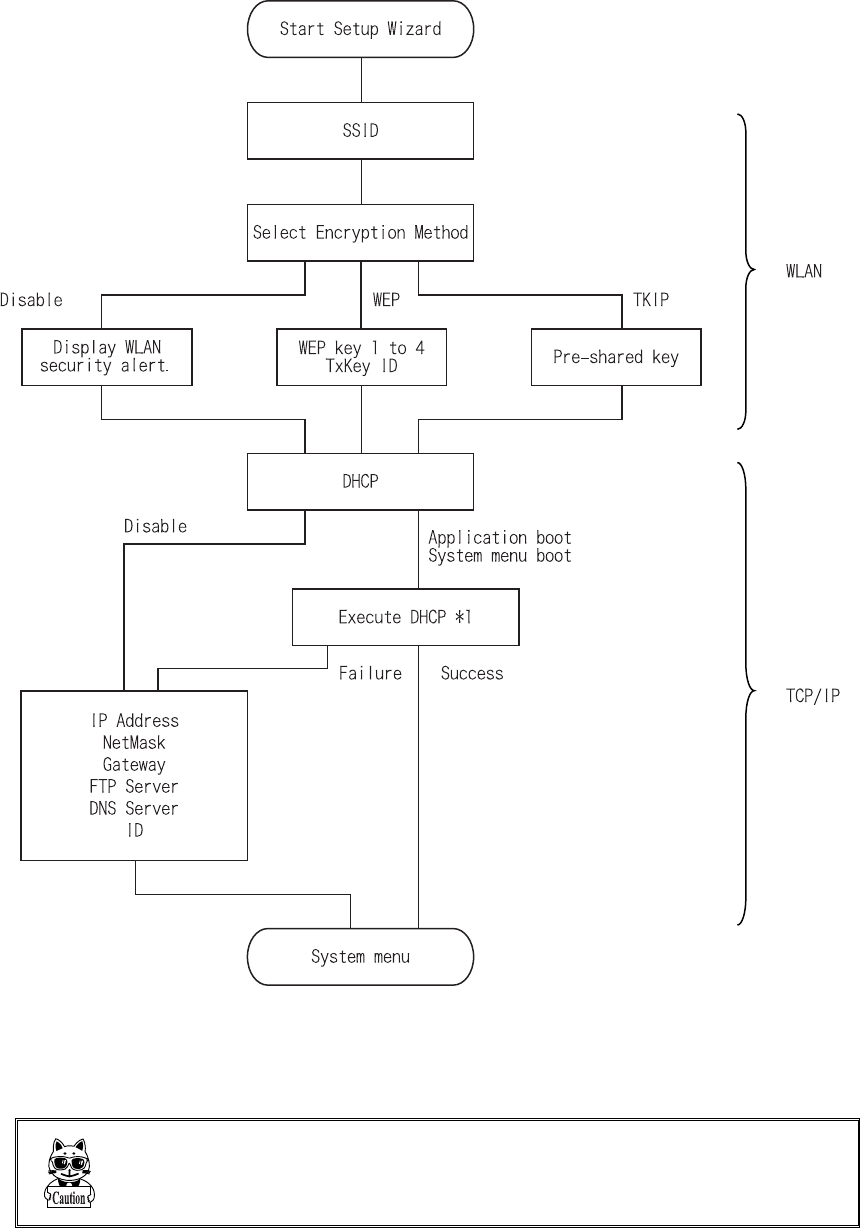
3-6 Starting the System Menu
3-11
With the Setup Wizard, each item is setup respectively according to the flow of the following Chart. The ac-
companying item differs by the branch of the selection.
*1 This is only performed by Wizard Execute when starting up the terminal. When "Wizard Execute" is per-
formed from the System menu (P.3-81). It returns to the System menu without executing DHCP.
WLAN authentication method is not allowed to setup by the wizard.
Especially IEEE802.1X requires receiving the files such as Certificate
etc., complicating the setup, please perform the setup manually.
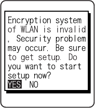
Chapter 3 System menu
3-12
3-6-5 WLAN Security Alert
When the WLAN Encryption Method is disabled, the dialog to alert the setup is displayed at the time of starting
up.
Select either from [Yes] or [No]
Select [Yes], moves to "2:WLAN". Select [No], System menu is displayed.
When the resume is enabled, this dialog is not displayed.
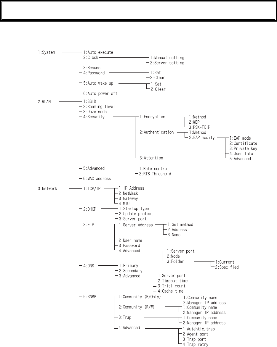
3-7 System Menu List
3-13
3-7 System Menu List
System menu is configured as a structural architecture that is classified for respective functions.
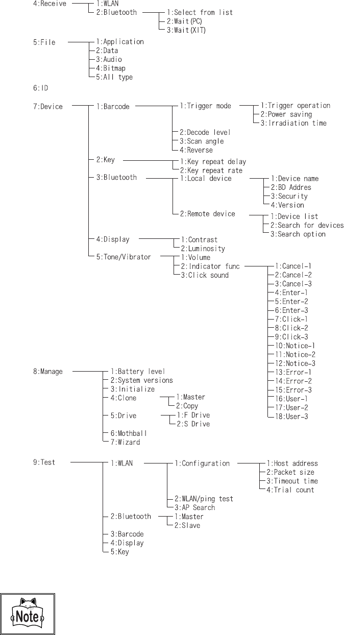
Chapter 3 System menu
3-14
Please refer to the "System menu Factory Settings" (Appendix A-2) for
information about the System menu factory settings.
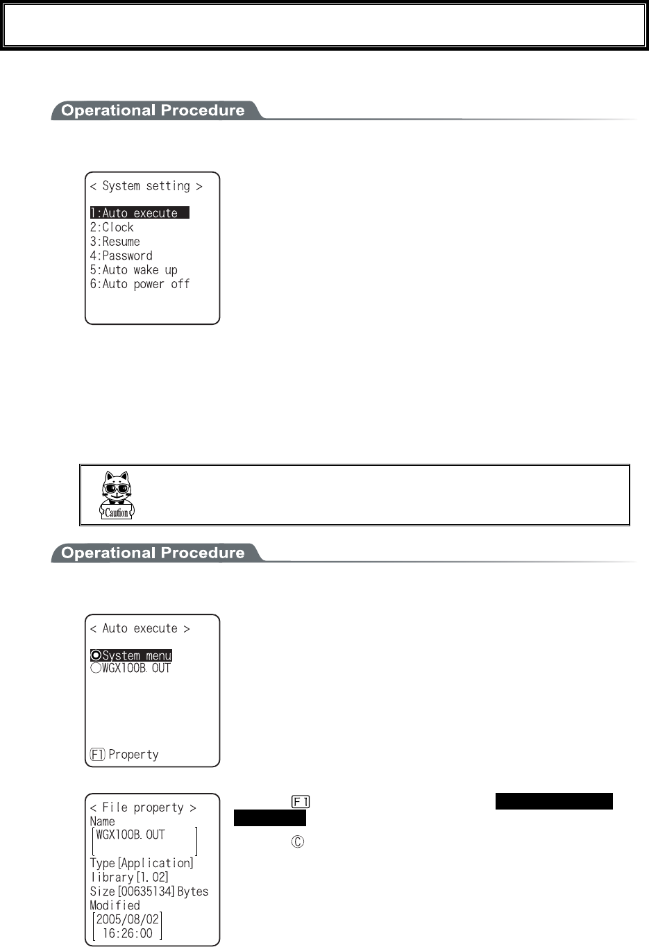
3-8 System Setup Menu
3-15
3-8 System Setup Menu
The setup for convenient functions to facilitate your XIT-100-BW.
1. From System menu, select "1:System".
Select the item to setup.
・ Auto execute
・ Clock
・ Resume
・ Password
・ Auto wake up
・ Auto power off
3-8-1 Setting the programs for Automatic Launch
You can set programs to launch automatically when the power is turned ON. In the factory settings, the System
menu is set to launch automatically. When the DHCP function is enabled, these settings can be made automati-
cally.
In the case to have the DHCP function enabled, refer to the
"WebGlider-X" Manual for details
1. From the System Setting Menu, select "1:Auto execute".
From the list, select "System menu" or "application program".
The current program name is displayed with dotted radio button.
Press the key, and information related to the Selected applica-
tion program is displayed.
Press the key, and return to the previous Menu.
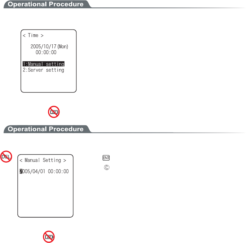
Chapter 3 System menu
3-16
3-8-2 Clock
This function is to confirm the current time, and set up the time.
In addition to Manual Setup, setting up the clock via the "Server Setting" to adjust the time of the terminal to that
of the host computer is possible, when the DHCP function is enabled.
■Current Time
1. From the System Setup Menu, select "2:Clock"
Current Time is displayed.
Select the item to setup.
・ Manual setting
・ Server setting
■Manual setting
1. Input the time data.
Press the key, and confirm the time.
Press the key to cancel setting and return to current
time.
■Server setting
Server setting, confirm the following beforehand.
・ WLAN communication setup(SSID, Security etc.) between the terminal and the access point is
correctly setup.
・ The power of the access point and the host computer is ON.
・ The access point and the host computer is correctly setup and connected.
・ The access point is normally operating.
・ DHCP server of the "WebGlider-X" Network manager is running.
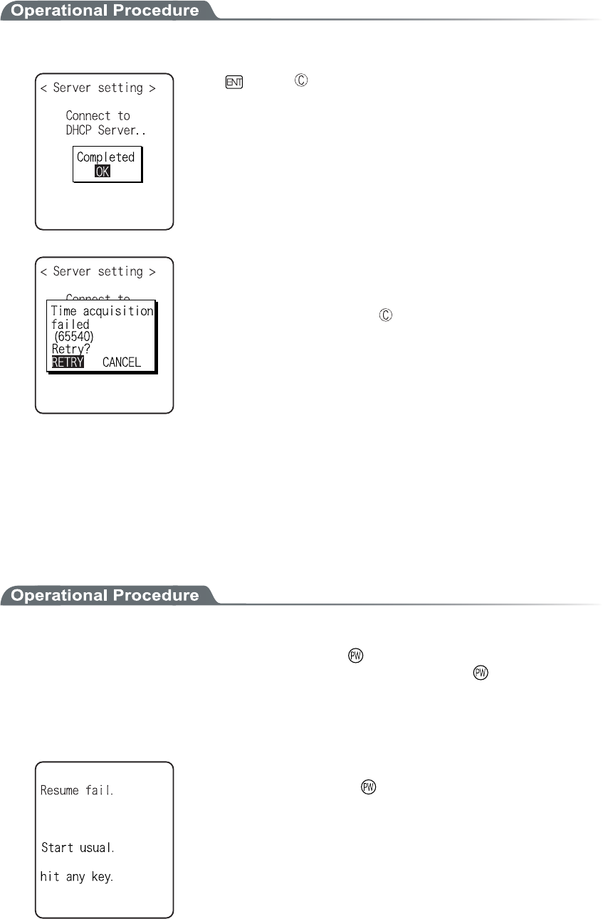
3-8 System Setup Menu
3-17
1. Receiving the time data from the DHCP of "WebGlider-X" Network Manager.
Press key or key to return to check the current time.
When receiving is failed, the screen on the left is displayed.
[Select RETRY], to receive the Time data from the server again.
Select [CANCEL], or Press the key to cancel setup and return
to Current time.
3-8-3 Resume (resume function)
The XIT-100-BW supports a resume function. The resume function can be enabled through the System menu
and if selected, the next time the key is pressed on the XIT-100-BW, the resume function will be used. Resume
mode ON after the XIT-100-BW is powered OFF, the next time the key is pressed, it will resume operation
where it was just before the power was turned OFF. For details of the resume function, please refer to the "1-10
Resume function"(P.1-25).
●Resume mode ON
After the XIT100B is powered OFF, the next time the key is pressed, it will resume operation
where it was just before the power was turned OFF. (Power ON, pressing the key while pressing
the scan key to cancel resume mode)
●Resume Fail
Resume setup will fail when the power OFF by removing the bat-
tery and without pressing the key.
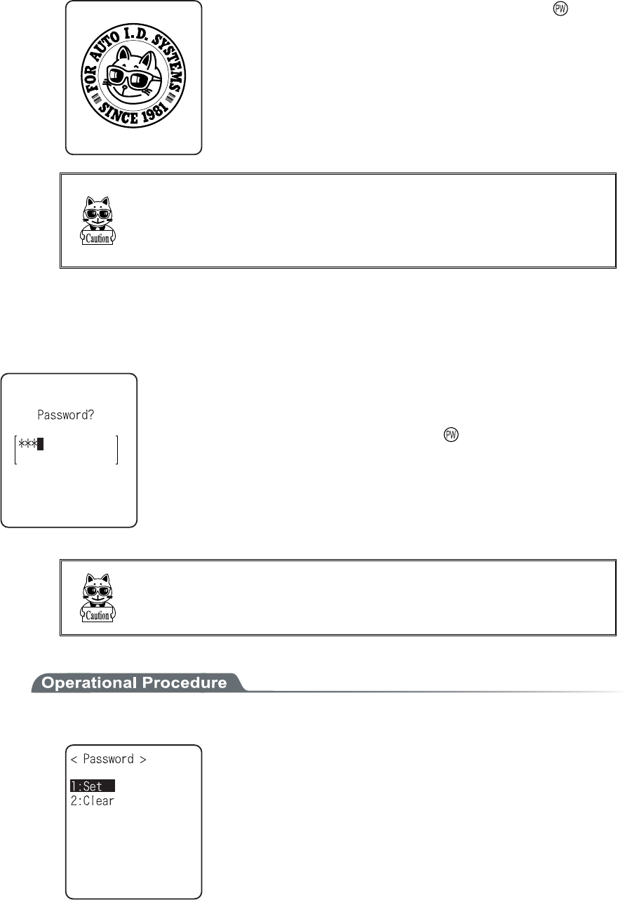
Chapter 3 System menu
3-18
●Resume mode OFF
After the XIT-100-BW is powered OFF, the next time the key is
pressed, it will begin operation from the start.
When the application is setup to " Auto Execute", the assigned appli-
cation will startup.
In the case where the battery is disconnected while the power is ON,
the operation will begin from the start regardless of the resume
mode settings. In order to enable the resume function, turn ON/OFF
the power by pressing the key.
3-8-4 Password
The password to avoid unnecessary running on of the System menu will be setup. By setting a password, the
third person other than the system administrator unable to confirm or modify the setup contents.
In case a password is setup, the password confirmation will be performed at the
time of starting up of the System menu. The System menu will not start up unless
the password is entered.
However, when the power OFF by pressing the key, with resume function
enabled, while System menu is displayed, the password check will not performed
when the terminal will restart from the System menu.
Be sure to take notes of the encryption number, and keep it so that
you may not forget it. In case you forget the number, please contact
our sales department.
1. From the System setup, select "4:Password".
Select the item to setup.
・ Set
・ Clear
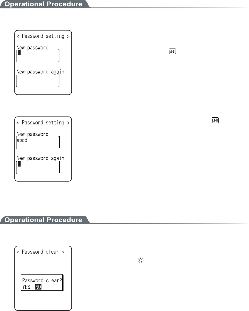
3-8 System Setup Menu
3-19
■Password setting
1. Input a new password.
Password should be alphanumeric characters from 4 to 30, Up-
per-case character/Lower-case character are distinguished.
Input a new password, then, press the key.
2. Input the password again.
After the password is entered, confirm by pressing the
key.
■Clearing a Password
1. From the confirmation dialog, select[Yes].
The setup password is erased.
Select [No], or press the key, and clear to stop.
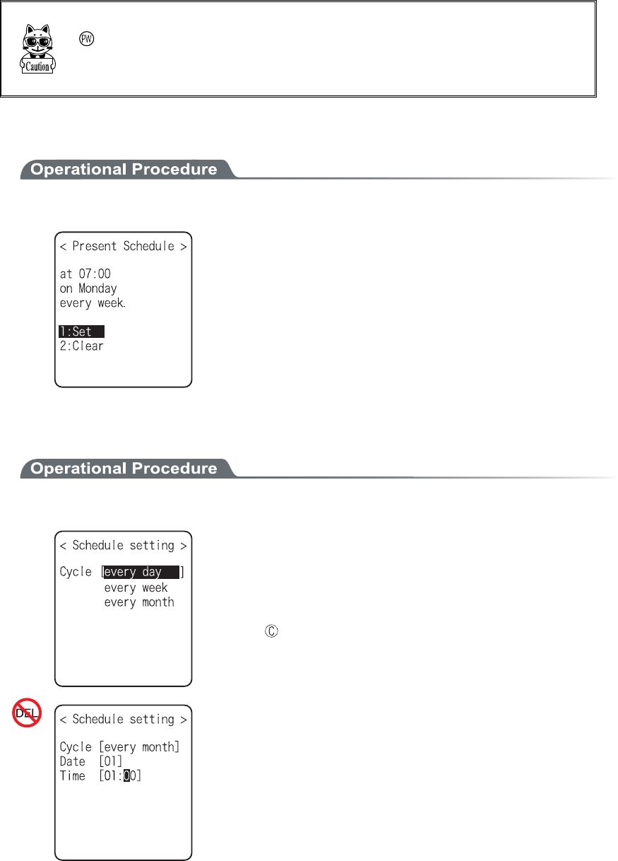
Chapter 3 System menu
3-20
3-8-5 Auto wake up
Auto wake up is a function to start up the terminal automatically according to the preset schedule. By combining
Auto wake up and DHCP Execute running on, which allow the application and the master file automatically up-
dated before starting operation.
Auto wake up function is enabled only when the terminal is closed by the
key. The terminal will not start up, even at the preset Auto wake up
time, when after replacing the battery or forced termination due to a low
battery.
■Schedule confirmation
1. From the System setup, select "5:Auto wake up".
Currently setup schedule is displayed.
Select the item to setup.
・ Set
・ Clear
■Schedule setting
1. Select Schedule accrual cycle.
Selected from among every day (time is specified), every week
(week and time are specified), and every month (date and time are
specified). Date is set from "01" to "31", time for 24 hours style.
When setting has completed, then return to Schedule confirma-
tion.
Press the key to stop setting and return to Schedule confirma-
tion.
Input the time in 24 hour-style (00:00 to 23:59).
Thus complete the setup, and return to Schedule confirmation.
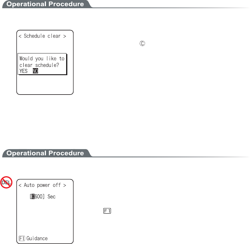
3-8 System Setup Menu
3-21
■Schedule Clearing
1. From the confirmation dialog, select[Yes].
The setup Schedule is erased.
Select [No], or Press the key to stop clearing.
3-8-6 Auto power off
Auto power off is a function to make the power OFF automatically when there is no operation performed for a
certain period.
1. From the System setup, then select "6:Auto power off".
Input the Auto power off time.
The time allowed to setup is from 0060 seconds to 3600 seconds. In
addition, when set to 0000 seconds, the Auto power off is disabled.
Press the key, and, setup value related guidance is displayed.
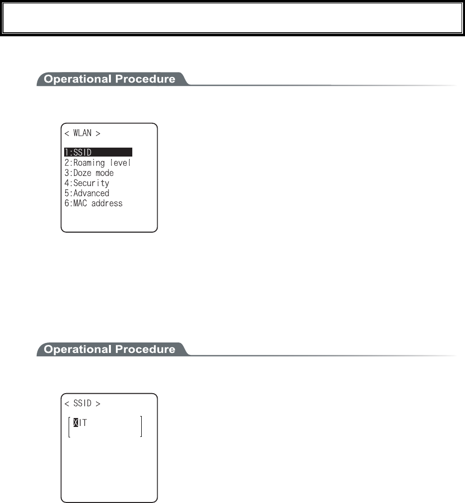
Chapter 3 System menu
3-22
3-9 WLAN Menu
Wireless LAN related setup is performed.
1. From the System menu, select "2:WLAN".
Select the item to setup.
・ SSID
・ Roaming level
・ Doze mode
・ Security
・ Advanced
・ MAC address
3-9-1 SSID
SSID setup. The characters allowed to enter are single-byte alphanumeric characters whose number should be up
to 32, and Upper-case character/Lower-case character is distinguished.
When DHCP function is enabled, automatic setup is possible, but this is not recommended as security problems
may occur.
1. From the WLAN, select "1:SSID".
Input the SSID.
SSID should be in alphanumeric character up to 32 charac-
ters, and Upper-case character/Lower-case character distin-
guished.
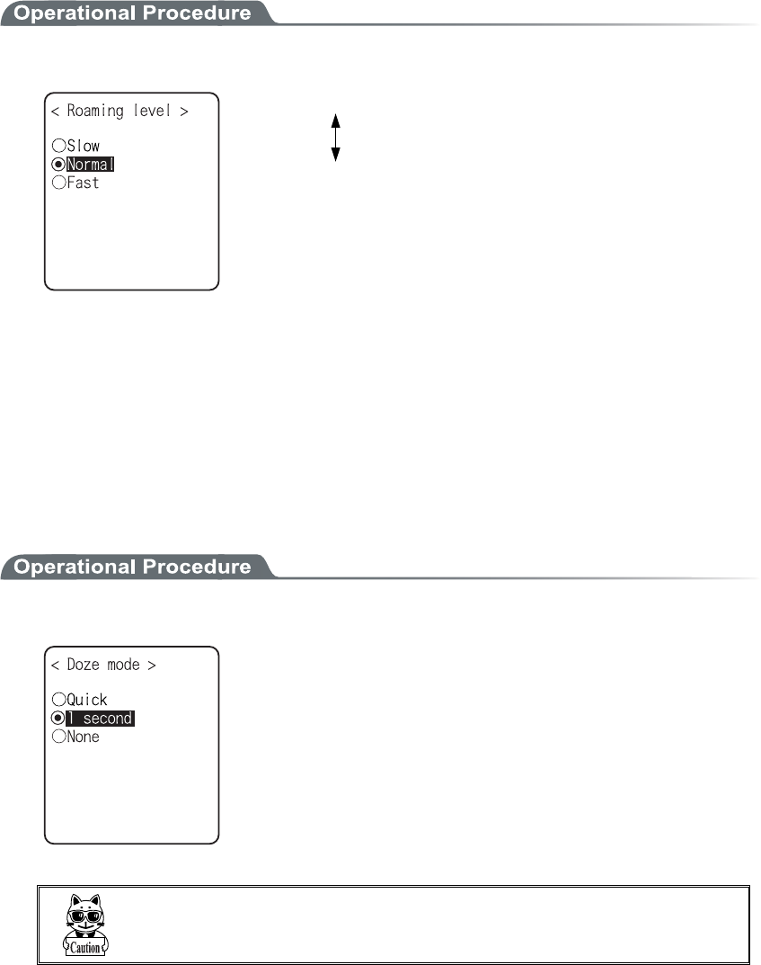
3-9 WLAN Menu
3-23
3-9-2 Roaming level
Roaming means a function, which switches the access point by choosing the access point with stronger radio
signal when the terminal moves. The roaming level created as the judgment value to judge whether to perform
the switching. When DHCP function is enabled, automatic setting is possible. The roaming is performs only be-
tween the access points with identical SSID.
1. From the WLAN, select "2:Roaming level".
Slow roaming is difficult to perform.
Normal
Fast roaming is easy to perform.
3-9-3 Doze mode
The time during which the WLAN switches into Doze mode after transmission finished.
The shorter this time is the less consumption of the battery pack becomes, however, the responsiveness of
WLAN decreases.
When DHCP function is enabled, automatic setting is also possible. The WLAN response time varies according
to the beacon cycle and DTIM setting of the access point.
For details about the beacon and DTIM, please refer to the access point's Manual.
1. From the WLAN, select "3:Doze mode".
Select the item to setup.
In the case to have the DHCP function enabled, please refer to the
"WebGlider-X" Manual for details
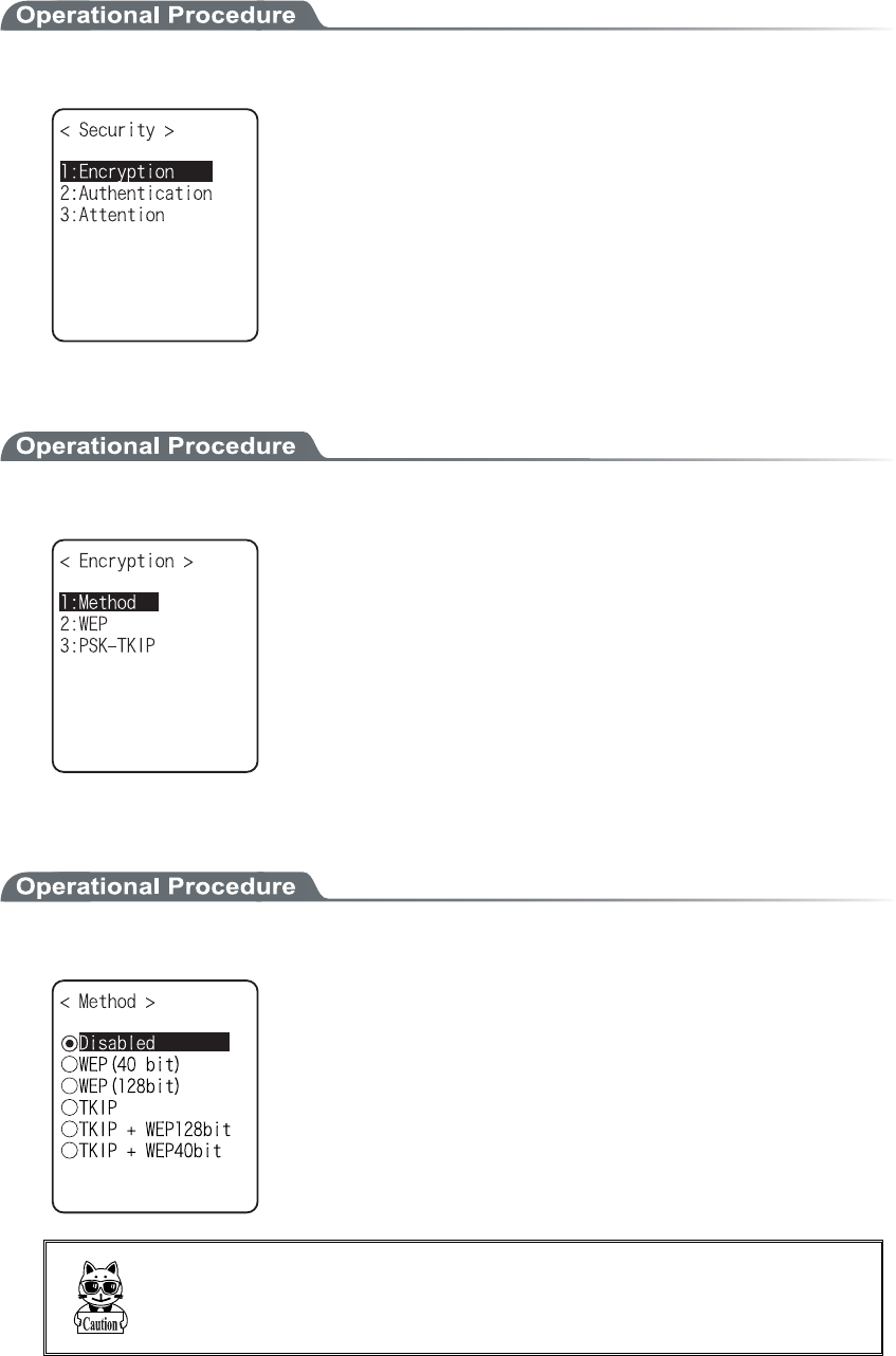
Chapter 3 System menu
3-24
3-9-4 Security
Security related setting of WLAN is performed.
1. From the WLAN menu, select "4:Security".
Select the item to setup.
・ Encryption
・ Authentication
・ Attention
■Encryption
1. Select the item to setup.
・ Method
・ WEP
・ PSK-TKIP
●Method
1. Select the item to setup.
Select the item to setup.
In the Authentication Method using "EAP"(P.3-28), communication
cannot be performed when "Disabled", "WEP (40bit)" or "WEP
(128bit)" is setup.
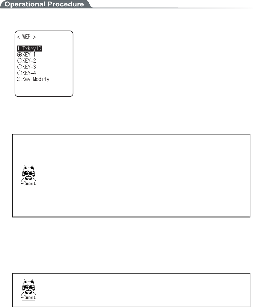
3-9 WLAN Menu
3-25
●WEP(Wired Equivalent Privacy)
Since IEEE802.11b is a general wireless standard, it may be easily intercepted by a third person. The
danger of data being intercepted between an access point and a terminal (XIT-100-BW) is avoidable
by using WEP, which is the standard of encryption of wireless communication.
XIT-100-BW is compliant with two kinds of WEP keys (common key), "40 bits (also called 64 bits)"
and "128 bits."
1. Select the item to setup.
From the sub menu, select the item to setup.
・TxKey_ID
Select the ID used for transmission from KEY1- KEY4 set in the next paragraph " KEY setup."
This becomes effective if the WEP settings are set to other than "Disabled."
Communication is possible only if the contents of both the WEP key
of selected Tx KEY_ID and the access point WEP key are the same,
and if the contents of both the Transmit KEY WEP key set on the
access point and the terminal's WEP key are the same. For example,
when the Tx KEY_ID of a terminal is set to "2," the contents of the
terminal WEP key 2 and the contents of the access point WEP key 2
need to be the same. On the other hand, when an access point
Transmit key is set to "3," the contents of the access point WEP key 3
and the contents of the terminal WEP key 3 need to be the same.
・KEY Setup
Setting the contents of each WEP key (1, 2, 3, 4). Characters which can be used are "0" - "9", "A" -
"F" and "a" - "f." When a 40 bits is Selected for "WEP," the WEP is a fixed 10 characters. When
128 bits is Selected, it is a fixed 26 characters. The number of characters that are actually input is
always 26. Therefore, when 40 bits is Selected, the first 10 characters of the 26 characters are ap-
plied. If a trigger key is pressed, the setup can be done by scanning a barcode.
Each WEP key setup can be overwritten but cannot be edited.
On entering the KEY setup screen, it displays "00000." for security
purposes.

Chapter 3 System menu
3-26
●PSK-TKIP
When PSK-TKIP is selected by encryption method, input the En-
cryption key, and perform the same setup as that of the access point.
When setup is performed in ASCII Characters, input the characters
from 8 to 63. When the set up is performed by 16-digit number, input
up to 64 characters.
When using PSK-TKIP, set the Authentication Method (P.3-28) to
"Open".
About TKIP function
XIT-100-BW stores "PSK-TKIP" as WLAN Security function.
■PSK-TKIP
・PSK
PSK means Pre-Shared Key. Before the wireless connection is performed between the access
point and the terminal the keys of the same encryption key are setup.
This key should go under strict management to avoid being known by the third person. In this
sense, the key setup in WEP is PSK.
・TKIP
TKIP (Temporal key Integrity Protocol) is a part of the Encryption Standard for
IEEE802.11i wireless LAN using an temporary key. This is a strengthened function of WEP
by using encryption algorithm RC4. The temporary key is not merely encrypted by RC4, but
by performing Key mixed processing in two steps to execute encryption for each packet with
different keys.
・PSK-TKIP
In this case, the PSK same as that of the access point is setup to the XIT-100-BW, and TKIP
is used as Encryption Method. In PSK-TKIP Method, PSK is not directly made into the en-
cryption key but by using random numbers for each cycles of connection between each access
point and the terminal or by using random number periodically thus creating a temporary key.
Due to this processing, some seconds delay occurs at wireless connection between the access
point compared to "Disabled" or "WEP".
■TKIP setup
●Group Key( Broadcast/Multicast Key )
When TKIP is used as the encryption method of XIT-100-BW, the Broadcast /Multicast Packet
transmitted from the access point to the entire wireless terminal, encryption is made in the
manner of encryption key called Group. According to the Encryption Method of the Group
Key setup at the access point (TKIP, WEP128bit, WEP40bit), the Group Key Encryption
Method of XIT-100-BW should be setup. (Refer to "TKIP Encryption Method").
●TKIP Encryption Method
In the TKIP related Encryption Method of XIT-100-BW, there are "TKIP",
"TKIP+WEP128bit" and "TKIP+WEP40bit". These setup are confirmed according to what is
used as the Group Key. Being depend on the setup of the access point, please confirm the setup
in line with the manual for the access point.
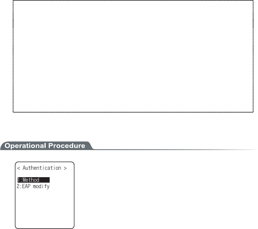
3-9 WLAN Menu
3-27
Encryption Method of XIT-100-BW is as follows.
・TKIP
Setup when the Group Key is TKIP. When one SSID setup is made at the access point, most
of them are this setup.
・TKIP+WEP128bit
Setup when the Group Key is WEP128bit. Many SSID of the access point are setup, when
WEP128bitis setup as the Group Key, the terminal is setup same as this setup (This is used
when you want to mix it at the same access point same terminal running by WEP128bit).
・TKIP+WEP40bit
Setup when the Group Key is WEP40bit. When many SSID of the access point's setup, and
WEP40bit is setup as a Group Key, the terminal is setup in this style (This is used if you want
to use this in the terminal of the same access point running at WEP40bit).
■Authentication
Select the item to setup.
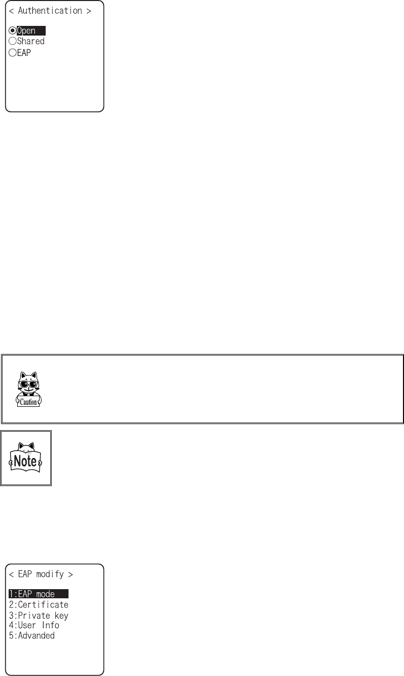
Chapter 3 System menu
3-28
●Method
・ Open
"Open Authentication" system.
If an authentication request frame from a terminal
(XIT-100-BW) is received, an access point will reply with an
authentication response frame, which will permit data commu-
nications.
When WEP is valid, authentication is possible but data com-
munications cannot be performed if both WEP keys do not
match.
・ Shared
"Shared Key Authentication" system.
If a terminal performs an authentication request, an access
point will transmit a non-encrypted identity request authentica-
tion text character string (hereinafter called as "challenge
code"). Then, the terminal replies a challenge code encrypted
using the WEP key. The access point decrypts the challenge
code via the WEP key and checks to see if it is the same as the
transmitted challenge code and if the same, permits authentica-
tion.
・ EAP
"EAP"(IEEE802.1X) Authentication system.
If this authentication method is used, Certificate, Private key,
user information setting etc. is needed. There is a limitation
also in the environment (Certification Authority (CA), authen-
tication (RADIUS) server etc.) that can be used. Therefore,
when using the "EAP" authentication method, please contact
our sales department.
If the challenge code before and after encryption is intercepted by a
third person, the WEP key is easily determined. The "Shared Key
Authentication" system thus creates a security weak point and
should not be used whenever possible.
Some access points do not disclose their authentication type. In this
case, please try "Open Authentication," and if connection is impos-
sible, try "Shared Key Authentication."
●EAP setup
When using the EAP (IEEE802.1X) authentication, the required items are set.
After setup, perform the "wireless/ping test" (P.3-84), and confirm that the communication by EAP
authentication is enabled.
Select the item to setup.
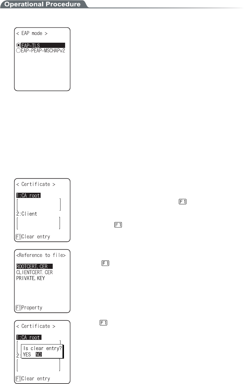
3-9 WLAN Menu
3-29
1. Select the mode.
・ EAP-TLS
Server certificate for server authentication, and client certifi-
cate for client authentication are the necessary authentication
method.
The necessary items for setting is as follows.
・CA root certificate
・Client certificate
・Private key
・User name
・ EAP-PEAP-MSCHAPv2
Server certificate for server authentication, while user name,
password for client authentication are the necessary authenti-
cation Method.
The necessary items for setting is as follows.
・CA root Certificate
・User name
・Password
2. Certificate file is setup.
Each certificate file is received via FTP (P.3-36) or Bluetooth (P.3-61).
・ CA root certificate(file)
The CA root certificate issued by the server certificate agency
required for server authentication. This does not support the
layered chain of certificate. Press the key to clear.
・ Client certificate(file)
Client certificate is necessary for client authentication.
Press the key to clear.
Select from received files.
(Press the key to refer the file Properties.)
Press the key to clear the setup contents.
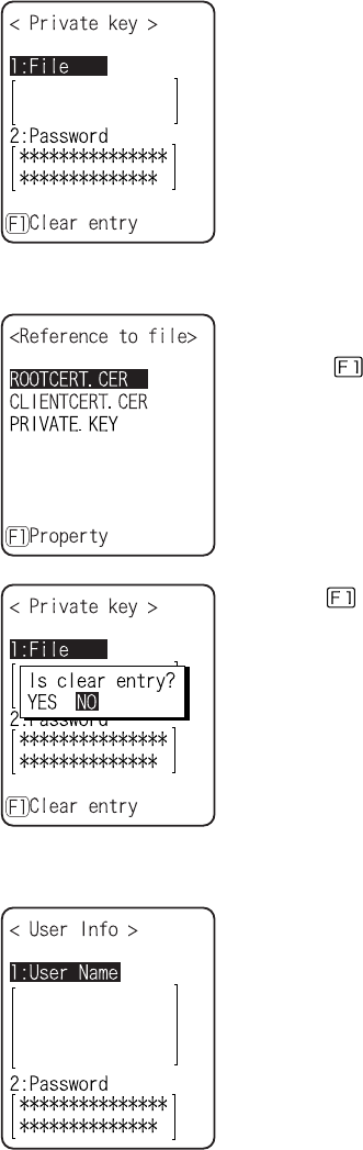
Chapter 3 System menu
3-30
3. Private key setting.
Private key(file) is received via FTP (P.3-36), or Bluetooth (P.3-61).
・File
Private key is in contrast to the client Open key included in the
client certificate. This private key is very important for security
reason. Encryption should be made on the private key file, and
manage so that the password is not known to the third person.
・Password
Single-byte alphanumeric characters from 0 to 31 characters
Upper-case character/Lower-case characters distinguished for
setup.
For security purpose, the input password after entered is
converted and displayed as the hidden character (*).
Select from the received files.
(Press the key to refer the file properties.)
Press the key to clear the setup contents.
4. Set up user information.
・ User Name
User name is used for authentication.
From 62 single-byte alphanumeric characters, it is set by dis-
tinguishing Upper-case character/Lower-case character.
・ Password
Password is used for authentication
From 0 to 31 single-byte alphanumeric characters, it is set by
distinguishing Upper-case character/Lower-case character. For
security purpose, the entered password is displayed being con-
verted as a hidden character" *".
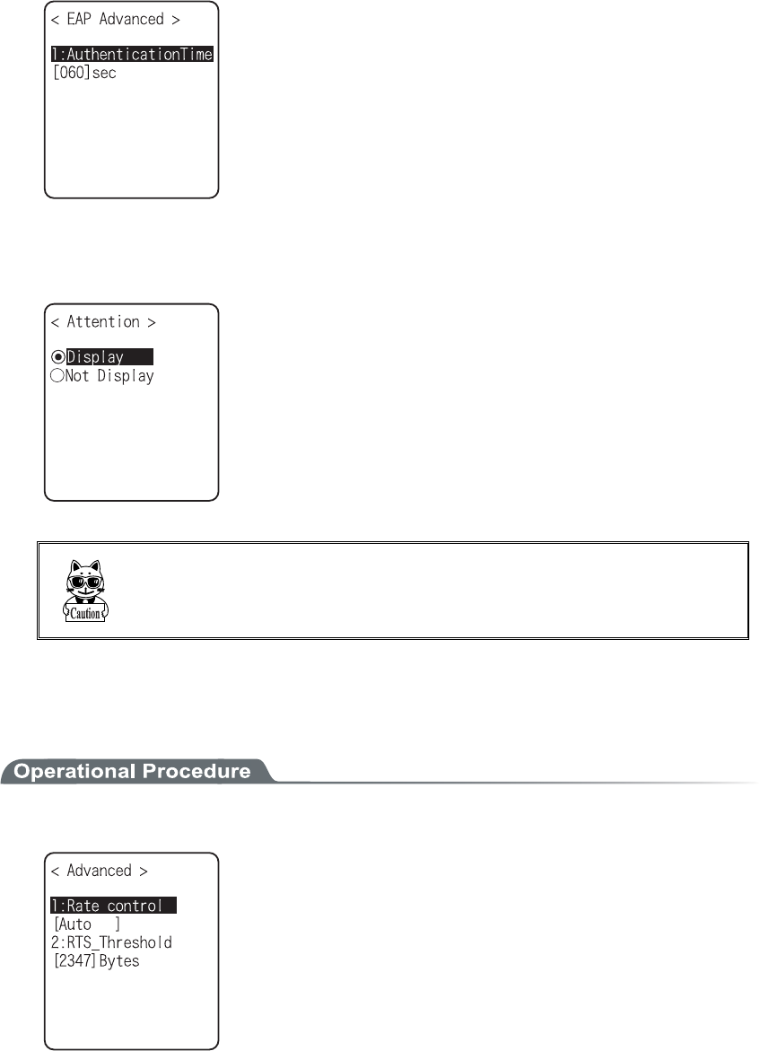
3-9 WLAN Menu
3-31
5. Setup the detail. This setup usually is not modified.
・At starting up authentication Time out
When WLAN start up, it waits the authentication to complete
up to the second setup here.
possible setup value :15 to 120 seconds
■Attention
The default is set to "Display".
In the case when the terminal is started up without WLAN security
setting, "WLAN Security setting" attention screen is displayed. By
setting this attention to OFF, this message is not displayed at starting
up even when WLAN security setting is disabled.
It is not recommended to set this Attention to setting to OFF, for
security reason. Be sure to perform security setting when using
WLAN communication.
3-9-5 Advanced
WLAN communication Advanced setting
1. From the WLAN, select "5:Advanced".
Select the item to set.
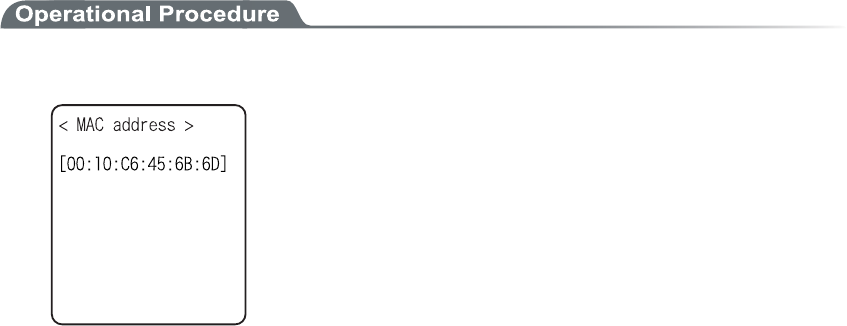
Chapter 3 System menu
3-32
●Rate control
Setup the transmission rate. When DHCP function (P.3-34) is used, the automatic setup is enabled.
Select any from the following. In addition, in the far distance, the high-speed communication cannot
be performed, if the transmission rate fixed with 5.5Mbps or more, the possible transmission area of
the terminal becomes narrow.
・ Auto
Automatically modified to a proper transmission speed according to the distance between the
terminal and the access point.
・ 1Mbps
Transmission speed is 1Mbps fixed.
・ 2Mbps
Transmission speed is 2Mbps fixed.
・ 1or2M
Transmission speed is automatically changed only at 1Mbps or 2Mbps.
・ 5.5M
Transmission speed is 5.5Mbps fixed.
・ 11M
Transmission speed is 11Mbps fixed.
●RTS Threshold
This determines whether an RTS packet is transmitted before transmission of a data packet. When the
size of a data packet is larger than the set value, an RTS packet is transmitted, and RTS-CTS control is
performed. When a large number of terminals are connected to the same access point, or terminals
cannot detect each other because they are dispersed remotely even if detection of an access point is
possible, RTS-CTS control becomes effective. Although RTS-CTS control is effective in this case, the
throughput reduces. Usually set it to the default value (2347 bytes).
・ Setting range:0 to 2347 bytes
3-9-6 MAC address
MAC address (hardware unique address) is displayed. MAC address cannot be changed.
1. From the WLAN, select "6:MAC address".