Welch Allyn FN802FH Propaq 802 LTRN User Manual Users Manal part 5 of 10
Welch Allyn, Inc. Propaq 802 LTRN Users Manal part 5 of 10
UserManual.wiki
>
Welch Allyn
>
FN802FH User Manual
>
Users Manal part 5 of 10
Contents
1.
Users Manual part 1 of 10
2.
Users Manual part 2 of 10
3.
Users Manual part 3 of 10
4.
Users Manual part 4 of 10
5.
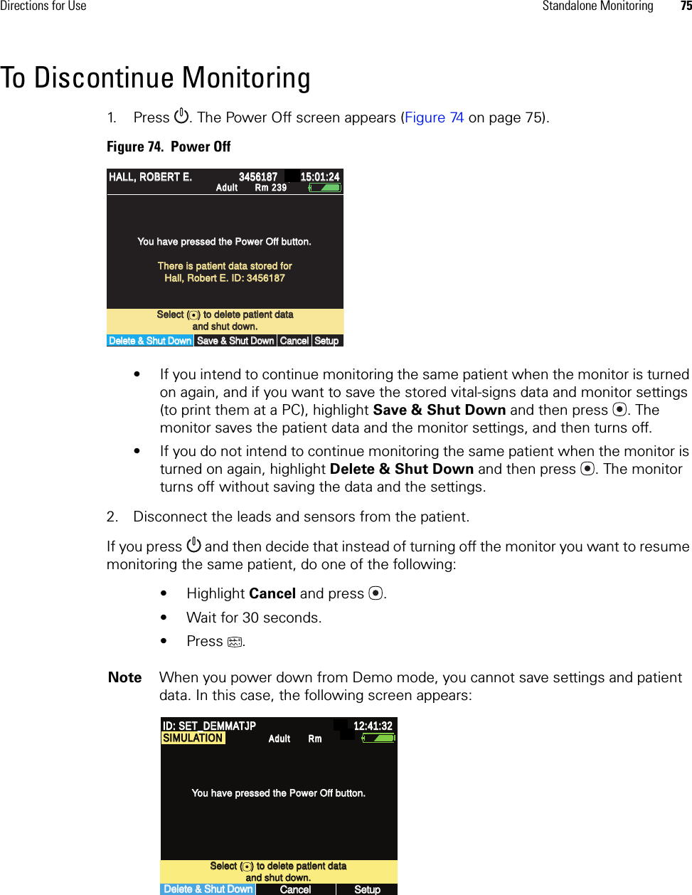
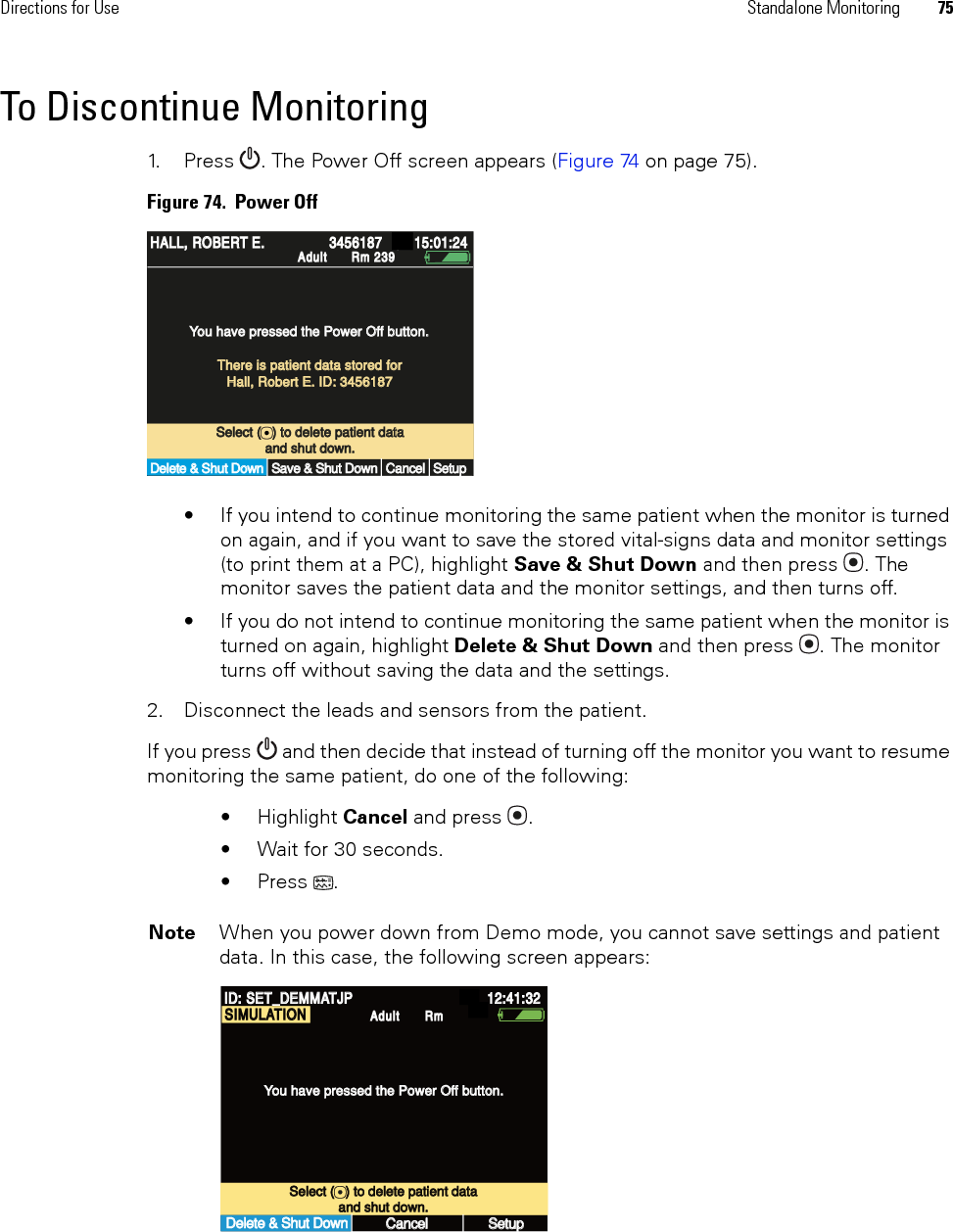
Users Manal part 5 of 10
6.
Users Manual part 6 of 10
7.
Users Manual part 7 of 10
8.
Users Manual part 8 of 10
9.
Users Manual part 9 of 10
10.
Users Manual part 10 of 10
Users Manal part 5 of 10
Navigation menu
Upload a User Manual
Namespaces
Wiki Guide
HTML
PDF
Info
Views
User Manual
Discussion / Help
Navigation