Welch Allyn WA11A07 Welch Allyn 802.11a Wireless PC Card User Manual Micropaq Monitor Directions for Use

Welch Allyn, Inc. Welch Allyn 802.11a Wireless PC Card Micropaq Monitor Directions for Use

Contents

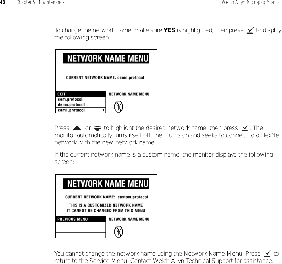
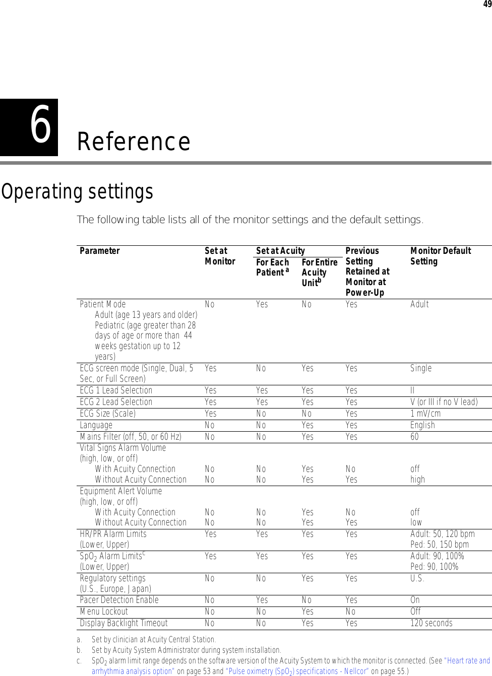
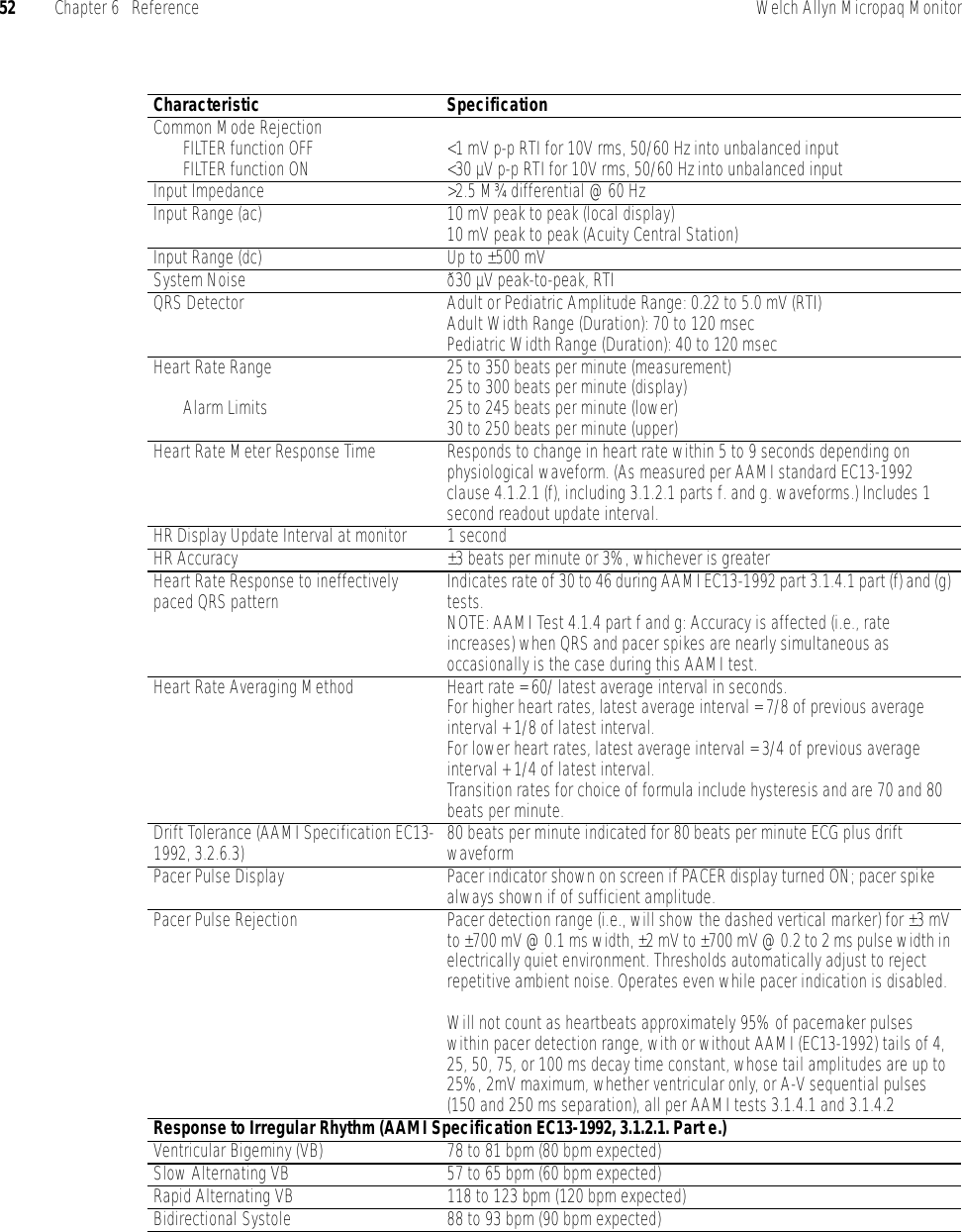
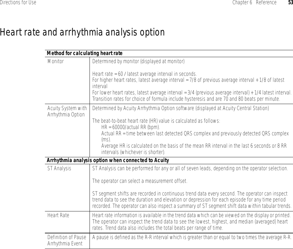
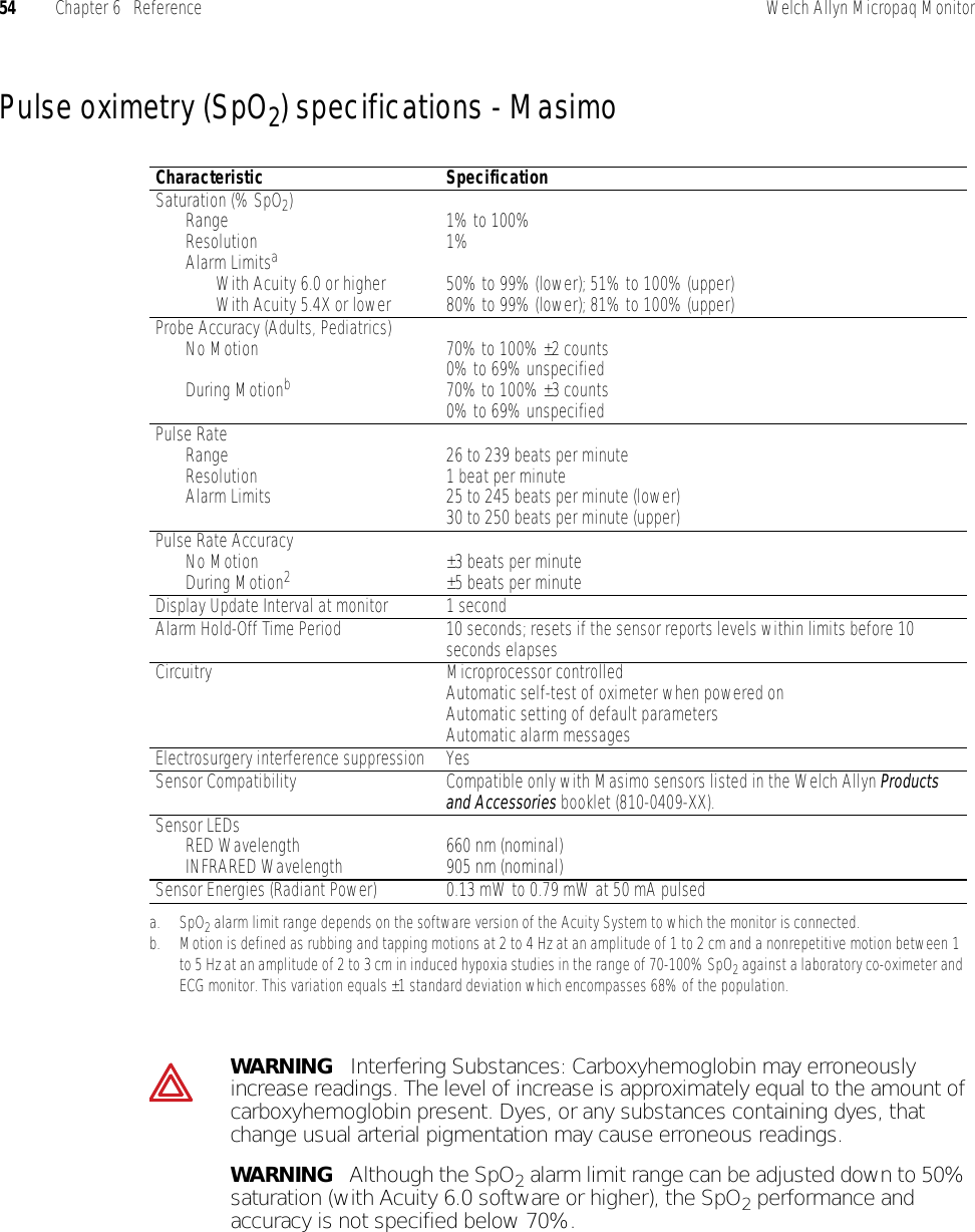
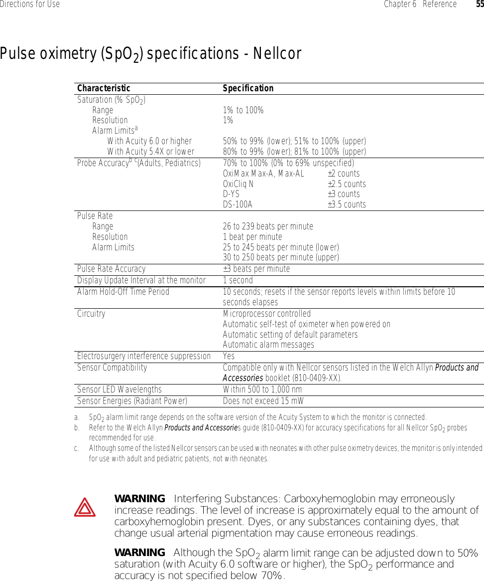
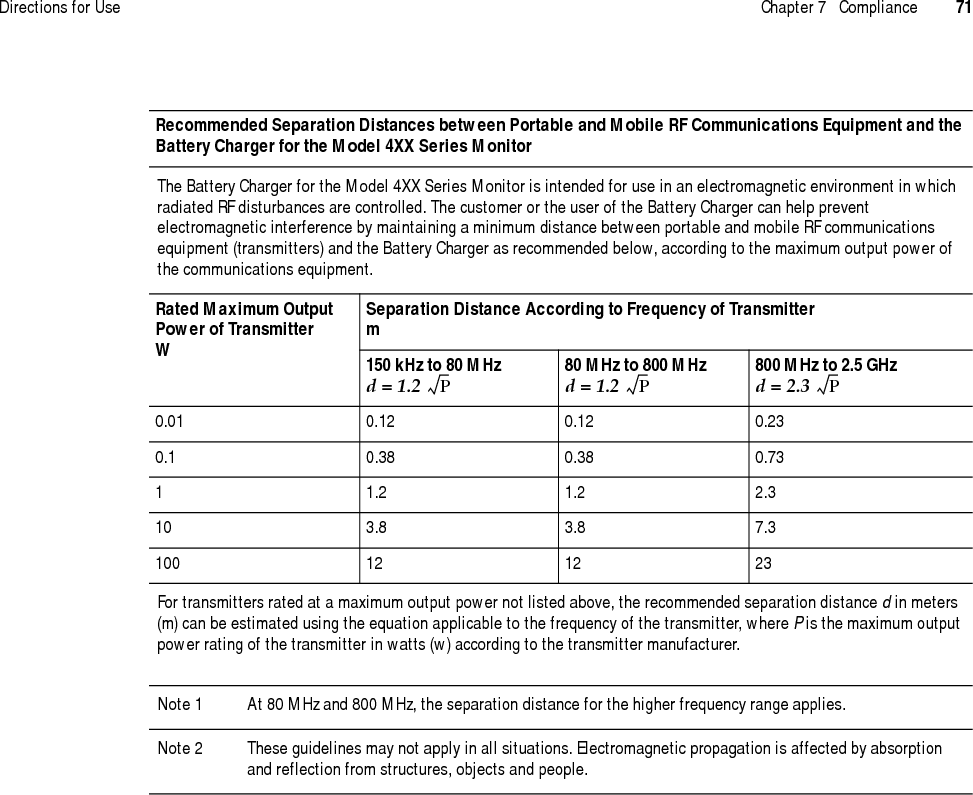
User Manual part 2 of 2

335Alarms & alertsAbout alarms and alertsAlarms provide a warning about a patient condition (such as a vital sign limit violation).Alerts provide a warning about an equipment condition that needs attention (such as a low battery or detached ECG lead).Alarms and alerts may be detected either by the monitor or by the network. While connected to the network, alarms or alerts are displayed at the monitor and at the Acuity Central Station. Alarms have a higher priority than alerts.Alarm holdoffsTo help minimize false alarms, the monitor briefly delays or “holds off” triggering alarms for limit violations for HR/PR or SpO2. After the alarm holdoff period begins, if the monitor detects that the patient’s vital sign has returned to acceptable limits, the monitor cancels the alarm holdoff. The next time a vital sign limit is violated, the monitor starts a new holdoff period.Vital Sign Alarm Holdoff PeriodHR 3 seconds% SpO2 or PR 10 seconds
36 Chapter 3   Alarms & alerts Welch Allyn Micropaq MonitorRespond to a patient alarm at monitorWhen a patient alarm occurs, the monitor produces an audible tone (if audible tones are enabled). Life-threatening arrhythmia alarms beep at a faster pace than other vital sign alarms (see “Patient alarm and equipment alert specifications” on page 56). The monitor also displays a message similar to the following:1. Check the patient and provide appropriate care.2. To silence the alarm tone at the monitor and the Acuity Central Station for 90 seconds, press  .While the alarm tone is silenced, visual alarm indications continue, and the red alarm indicator on the monitor changes from a flashing display to a continuous display.If the alarm condition still exists after 90 seconds, the alarm tone resumes. If you suspend an alarm at Acuity, only life-threatening arrhythmia alarms interrupt the silence period at the monitor and Acuity.To access the Main Menu during silencing, press  .Press to silence the alarm tone.Red LED flashesduring alarm.After the alarm issilenced (orsuspended atAcuity), the redLED is oncontinuously.Flashing numerics indicate patient alarm.NoteIf you silence an alarm at the monitor and another patient alarm or an equipment alert occurs during the silence period, the tone resumes at the monitor. At Acuity, only life-threatening arrhythmia alarms interrupt the silence period.
Directions for Use Chapter 3   Alarms & alerts 373. To reset the alarm tone at the monitor and Acuity before the 90 seconds has elapsed, press   at the monitor, or press Resume at the Acuity Central Station.4. After caring for the patient, make sure that the appropriate alarm limits are set and that alarms are on.Customize patient alarm limits at the monitor1. Press   to display the Main Menu.2. Press  to highlight LIMITS, then press   to display the Alarm Limits Adjust Menu:3. To change an alarm limit, press   or   to highlight the desired limit, then press  to display the Threshold Adjustment Menu:• Scroll and select the + or - selections to change the limit as desired.• To turn the highlighted limit on or off, scroll to ON/OFF and press  .WARNING   If the patient’s name has not yet been assigned to the monitor, do not adjust any alarm limits until after the patient name and ID are confirmed at Acuity. When the patient name and ID are confirmed at Acuity, Acuity downloads the default settings and patient alarm limits for that Acuity unit, thereby overriding any custom alarm limits that were set at the monitor before selecting the patient.Alarm limits can be adjusted for HR/PR and SpO2.Select + or - to change the limit.
38 Chapter 3   Alarms & alerts Welch Allyn Micropaq Monitor4. To change other limits, scroll to PREVIOUS MENU, press  , then select another limit to change.5. When you have completed all changes, scroll to PREVIOUS MENU, then EXIT on the Alarm Limits Adjust Menu and press   to return to the normal monitoring screen.Respond to an equipment alert at the monitorWhen the network or the monitor detects an equipment problem, the monitor produces a an audible alert tone (if audible tones are enabled). Equipment alerts beep at a slower pace than patient vital sign alarms (see “Patient alarm and equipment alert specifications” on page 56). The monitor also displays a flashing yellow light (LED) and an equipment alert message similar to the following:1. In this instance, press   to acknowledge (dismiss) the alert tone and clear the message. If the message says “PRESS   TO SILENCE,” when you press  , the tone is silenced for 90 seconds instead of dismissed.If the monitor displays a chest diagram with a missing lead flashing, you can press  to silence the tone. Some alerts do not give you the option to acknowledge the alert or silence the tone. For these alerts, to remove the message and tone, you must correct the problem.WARNING   If you turn off any alarm limits, be sure to restore the appropriate alarm limits before you resume monitoring. Only life-threatening arrhythmias will be indicated at the monitor and Acuity (if connected) when alarms are turned off.NoteWhile the monitor is connected to Acuity, settings can be changed either at the monitor or at Acuity.The monitor has detected that the ECG cable has been disconnected from the monitor.
Directions for Use Chapter 3   Alarms & alerts 392. If possible, determine what caused the problem and correct it. For a list of possible messages and suggested responses, see “Alert messages and display information” on page 40.NoteAfter you press  to acknowledge or silence some types of alerts, the yellow LED remains on (either flashing or steady yellow) until you correct the problem. For low battery alerts and no Acuity connection alerts, specific icons also flash.
40 Chapter 3   Alarms & alerts Welch Allyn Micropaq MonitorAlert messages and display informationMessage and Display Information Possible Cause(s) and Suggested ResponseLOW BATTERY The monitor will shut down within approximately 30 minutes or less due to a low battery.• Replace the battery as soon as possible.VERY LOW BATTERY The monitor will shut down within approximately 5 minutes or less due to a low battery.• Replace the battery as soon as possible.BATTERY TOO LOWSHUT DOWN IN PROGRESS The battery is so low the monitor has to shut down operation.• Replace the battery immediately.ACUITY CONNECTION LOST The monitor is not connected to the network.• Press   to acknowledge and silence the tone and cancel the message. While disconnected from the network, the off-network icon and the yellow LED continue to flash.NOTE: The monitor will continue to attempt to reconnect until it is successful.EXCESSIVE ECG OFFSETREPLACE ELECTRODESaa. This alert message can be acknowledged from Acuity, but not from the monitor.The monitor detects poor ECG electrode contact.• Check and replace ECG electrodes as needed.Chest icon is displayed with flashing ECG electrode(s).aThe monitor detects that one or more ECG electrodes are disconnected.• Check and replace or reconnect electrodes as needed.NO ECG CABLE DETECTED • If the ECG cable has been intentionally removed from the monitor, press  to cancel the alert tone.• If the ECG cable has been unintentionally removed, plug it back into the monitor. Check the patient and monitor to make sure ECG monitoring resumes properly.• It is normal for this alert to appear with a 3-lead ECG cable when two or more of its leads are disconnected from the patient. Reconnect the disconnected lead wires.NO SPO2 SENSOR DETECTED The SpO2 sensor has been disconnected for more than 5 seconds.• If disconnection is intentional, press  to acknowledge and silence the tone.• If disconnection is not intentional, reconnect the sensor or replace the sensor and reconnect.DEFECTIVE SPO2 SENSORaorUNRECOGNIZED SPO2 SENSORaThe SpO2 sensor is either defective or not recognized.• Replace the SpO2 sensor with a new, compatible SpO2 sensor.<key name> KEY STUCKaDuring the power-up self test, the monitor detected that a key is stuck ( ,  ,  , or  ). This can happen if you accidentally press a key down before the Main Menu is displayed during power-up.• Remove and then reinsert the battery to power up again and see if the key is still stuck. If it is, contact your biomedical engineering department.System ErrorThread: <nnn>Error ID: <nnn>The equipment problem is so serious the monitor cannot be used.• Contact your biomedical engineering department.
441Monitor patient at AcuityWhile the Micropaq is connected to the FlexNet network, patient data gathered by the monitor is continuously stored at Acuity. You can access this patient information at the Acuity Central Station and perform administrative functions, including:• Admit (and discharge) a patient in the Acuity unit.• Edit the patient description (name, physician, etc.).• Review and print patient data such as trends and waveforms.• Suspend patient alarm tones for 90 seconds and resume the alarm tonesFor more information about using the Acuity Central Workstation, refer to:• Acuity Directions For Use
42 Chapter 4   Monitor patient at Acuity Welch Allyn Micropaq Monitor
543MaintenanceThis section provides information to help operators of the monitor and the battery charger perform routine maintenance activities such as changing or recharging batteries, inspection, and cleaning.Change the battery1. Remove the depleted battery.2. Insert a fully-charged battery. Use only batteries supplied by Welch Allyn.Recharge a battery Eight-bay battery charger1. On the monitor battery charger (008-0651-XX), choose an empty battery well where the LED is off.2. Insert the depleted battery into the battery well.3. Confirm that the charger displays a flashing green LED by the battery to indicate the battery is detected or is charging.4. When the green LED is on continuously, the battery is fully charged. Remove the battery.WARNING   Before installing a battery, carefully inspect the battery case. If there are any signs of damage, cracks, or leaks, discard the battery properly and do not use it.NoteThe Acuity unit can be configured to allow you a short time (typically 30 seconds or more) to change the monitor battery while the monitor is connected to the network without causing an Acuity equipment alert. If the monitor is connected to the network and the battery is removed for longer than the allowable battery changing time, Acuity generates a DROPOUT equipment alert at the Acuity Central Station.
44 Chapter 5   Maintenance Welch Allyn Micropaq MonitorIf the yellow LED is on continuously, the battery may have reached the end of its useful life. Refer to the table below for suggested responses.The charger can accommodate up to eight batteries. The charger charges a maximum of four batteries at a time. After a battery begins recharging (as indicated by the green LED that flashes on one second, off one second), it is typically fully recharged within four hours at room temperature. After a battery is fully charged, the charger continues to maintain the full charge on the battery until the battery is removed. Leaving a fully-charged battery in the charger will not harm the battery.Remove batteries from the battery charger if the battery charger will be disconnected from ac power for more than a few days. Do not block the cooling vents at the rear of the battery charger.The monitor battery charger only charges four batteries at a time. A battery is not fully charged until the green LED is on continuously. Do not remove a battery until it is fully charged, or displays a battery fault.Charger LED Battery Charger Label—LEDs Battery Status and Possible ResponseGreen LED on continuously Battery is fully charged.Green LED flashing Battery is charging.Green LED flashing very slowlyBattery is detected and waiting to be charged.LED off No battery is detected.Yellow LED on continuously Something is wrong with the battery or the charger. Remove the battery.• If the LED goes off, it is probably a battery problem. Insert a new battery into the same battery well. If the new battery charges correctly, then the battery has a problem; discard the battery. The battery reorder number is 008-0647-XX. If the same problem occurs with the new battery, the charger may need repair. Contact biomedical engineering.• If the LED does not go off when you remove the battery, it is probably a charger problem. Unplug the charger power cord, wait at least 5 seconds, then plug in the charger power cord again. Insert a new battery into the same battery well. If the new battery charges correctly, then the battery has a problem; discard the battery. If the same problem occurs with the new battery, the charger may need repair. Contact biomedical engineering.WARNING   The monitor battery is Lithium Ion. Do not incinerate, submerge, crush, disassemble, or autoclave. If a battery has been submerged in liquid, discard the battery properly; do not try to recharge or reuse the battery. Do not short the battery terminals. Do not try to connect the battery to any device except the monitor or the monitor battery charger. Do not expose to high temperature (above 60° C or 140° F). Use only the specified monitor battery charger.
Directions for Use Chapter 5   Maintenance 45Inspect and clean the monitor and accessoriesBefore cleaning, thoroughly inspect the monitor and all accessories for any signs of damage, cracks, or improper mechanical function of keys or connectors. While gently bending and flexing cables, inspect for damage, cracks, cuts, abrasions, extreme wear, exposed wires or bent connectors. Confirm connectors securely engage. Report damage or improper function to your service department. At least every 12 months, be sure to thoroughly inspect the battery charger case and power cord for damage or extreme wear.To clean the monitor, batteries, or battery charger:1. Wipe the equipment with a nearly dry cloth moistened with one of the approved cleaning solutions listed in the table on “Approved Cleaning Solutions” on page 46.2. After cleaning, thoroughly wipe off any excess cleaning solution with a soft cloth dampened with water, then dry. Do not let the cleaning solution run into or accumulate in connector openings, latches, or crevices. If liquid gets into a battery well or connectors, dry the area with warm air, then check the equipment to confirm that it operates properly.WARNING   Be sure to unplug the monitor battery charger power cord from the electrical power outlet before inspecting or cleaning the battery charger. Exposing the battery charger to liquids such as cleaning solutions while connected to electrical power could result in electrical shock or fire.WARNING   Do not autoclave the monitor, battery, battery charger, or accessories. Do not immerse the monitor, battery, or battery charger in liquid when cleaning. Do not immerse accessories in liquid when cleaning unless the accessory manufacturer’s cleaning instructions explicitly instruct you to do so.Caution   Use only cleaning solutions which are recommended by Welch Allyn for this equipment. Use of solutions which are not recommended or which have a high acid content or are otherwise inappropriate can cause damage to the equipment, including cracking and deterioration of the plastic case. Do not use these solutions or similar products: Butyl alcohol, Denatured ethanol, Freon™, Mild chlorine bleach solution, Isopropyl alcohol (except for the SpO2 cable), Trichloroethane, Trichloroethylene, Acetone, Vesphene II, Enviroquat®, Staphene®, Misty®, Virex®, Glutaraldehyde, Formula 409®, or Fantastik®.
46 Chapter 5   Maintenance Welch Allyn Micropaq MonitorRecycling monitor componentsWhen the battery, monitor, or battery charger reaches the end of its life, recycle it locally according to national, state, and local regulations. You can also return the battery, monitor, or charger to Welch Allyn for recycling.Within the European UnionDo not dispose of this product as “unsorted municipal waste.” Prepare it for reuse or separate collection as specified by Directive 2002/96/EC, as amended, of the European Parliament and the Council of the European Union on Waste Electronic and Electrical Equipment (WEEE).If the monitor or battery (Li++) is contaminated, this directive does not apply. For more specific information, see www.welchallyn.com/weee, or contact Welch Allyn Customer Service.Recycle monitor batteries (Li++) according to the Directive 91/157/EEC (Batteries and accumulators containing certain dangerous substances) and Directive 93/86/EEC (Labelling of batteries and accumulators containing certain dangerous substances).Equipment Cleaning Instructions Approved Cleaning SolutionsMonitoraBatteryaBattery Chargersaa. The equipment may be disinfected to comply with OSHA requirements for cleaning and decontaminating spills of blood and other body fluids. (Federal OSHA Standard on bloodborne pathogens: 29 CFR 1910.1030, 12/6/91.)• Wipe with a nearly-dry cloth moistened with cleaning solution.• After cleaning, remove excess cleaning solution with a soft cloth dampened with clean water, then dry. Do not let cleaning solution run into connector openings or crevices.bb. If liquid gets into the battery well or connectors, dry the area with warm air, then check the monitoring functions for proper operation.Warm water, Liquid soap, Coverage®, Windex®, Ovation®, Hydrogen peroxide solution, Wex-cide®c, T.B.Q.®cc. Wex-cide (Wexford Labs, Inc., Kirkwood, MO) and T.B.Q. (Calgon Vestal Lab., Calgon Corp., St. Louis, MO) are disinfectants that meet OSHA requirements, are EPA approved, and will not harm the outside of the monitor, battery, or battery charger. Wipe away disinfectants with a water-dampened cloth after the manufacturer’s recommended period.ECG cable, extension cable • Wipe gently with damp cloth moistened with a mild detergent solution.• Thoroughly wipe off any cleaning solution.Mild detergent.SpO2 cable, extension cable • Wipe the cable with a 70% isopropyl alcohol pad and allow it to dry. 70% isopropyl alcohol pad.Other accessories • Consult manufacturer’s instructions. Consult manufacturer’s instructions.Li++
Directions for Use Chapter 5   Maintenance 47Change the network nameThis procedure allows you to change the network name assigned to the monitor (as long as the current network name is one of the pre-set names available in the monitor Network Name Menu).To change the network name:1. Press  to access the Main Menu, then repeatedly press   until SERVICE MENU is highlighted.2. Press   to display the Service Menu screen.3. Press and hold   and  , then press   to display the Network Name Menu.If the current monitor network name is one of the following pre-set names:then the monitor displays the following screenNoteChanging the monitor network name will cause the monitor to re-start and seek to connect with the FlexNet network corresponding to the new name. Do not attempt to change the network name unless you are a qualified biomedical service engineer or technician.com.protocol demo.protocolcom1.protocol com2.protocolcom3.protocol com4.protocolcom5.protocol com6.protocolcom7.protocol com8.protocol
48 Chapter 5   Maintenance Welch Allyn Micropaq MonitorTo change the network name, make sure YES is highlighted, then press   to display the following screen:Press   or   to highlight the desired network name, then press  . The monitor automatically turns itself off, then turns on and seeks to connect to a FlexNet network with the new network name.If the current network name is a custom name, the monitor displays the following screen:You cannot change the network name using the Network Name Menu. Press   to return to the Service Menu. Contact Welch Allyn Technical Support for assistance.
649ReferenceOperating settingsThe following table lists all of the monitor settings and the default settings.Parameter Set at Monitor Set at Acuity Previous Setting Retained at Monitor at Power-UpMonitor Default SettingFor Each Patient aa. Set by clinician at Acuity Central Station.For Entire Acuity Unitbb. Set by Acuity System Administrator during system installation.Patient ModeAdult (age 13 years and older)Pediatric (age greater than 28days of age or more than  44weeks gestation up to 12years) No Yes No Yes AdultECG screen mode (Single, Dual, 5 Sec, or Full Screen) Yes No Yes Yes SingleECG 1 Lead Selection Yes Yes Yes Yes IIECG 2 Lead Selection Yes Yes Yes Yes V (or III if no V lead)ECG Size (Scale) Yes No No Yes 1 mV/cmLanguage No No Yes Yes EnglishMains Filter (off, 50, or 60 Hz)  No No Yes Yes 60Vital Signs Alarm Volume(high, low, or off)With Acuity ConnectionWithout Acuity Connection NoNo NoNo YesYes NoYes offhighEquipment Alert Volume(high, low, or off)With Acuity ConnectionWithout Acuity Connection NoNo NoNo YesYes NoYes offlowHR/PR Alarm Limits(Lower, Upper) Yes Yes Yes Yes Adult: 50, 120 bpmPed: 50, 150 bpmSpO2 Alarm Limitsc(Lower, Upper)c. SpO2 alarm limit range depends on the software version of the Acuity System to which the monitor is connected. (See “Heart rate and arrhythmia analysis option” on page 53 and “Pulse oximetry (SpO2) specifications - Nellcor” on page 55.)Yes Yes Yes Yes Adult: 90, 100%Ped: 90, 100%Regulatory settings(U.S., Europe, Japan) No No Yes Yes U.S.Pacer Detection Enable No Yes No Yes OnMenu Lockout No No Yes No OffDisplay Backlight Timeout No No Yes Yes 120 seconds
50 Chapter 6   Reference Welch Allyn Micropaq MonitorSpecificationsMonitor radio specifications (5 GHz)Monitor radio specifications (2.4 GHz)Characteristic SpecificationFlexNet™ Network 5 GHz orthogonal frequency division multiplexing (OFDM) wireless local area network (WLAN) and 10/100/1000 base-T Ethernet networkModulation OFDMOutput power 40 mW maximum; country-dependentIEEE standards 802.11a, 802.11e, 802.11h, 802.1XMonitors per access point 20 (max.)Restrictions for use in the 5 GHz bandsaa. This device may be not be operated outdoors when using the bands 5150 to 5350 MHz (Channels 36, 40, 44, 48, 52, 56, 50, 64).Allowed frequency bandsbb. This device must be used with Access Points that have employed and activated a radar detection feature required for European Community operation in the 5GHz bands. This device will operate under the control of the Access Point in order to avoid operating on a channel occupied by any radar system in the area. The presence of nearby radar operation may result in temporary interruption in communications of this device. The Access Point’s radar detection feature will automatically restart operation on a channel free of radar. You may consult with the local technical support staff responsible for the wireless network to ensure the Access Point device(s) are properly configured for European Community operation.Allowed channel numberscc. To remain in conformance with European spectrum usage laws for Wireless LAN operation, the above 5 GHz channel limitations apply. The user should check the current channel of operation. If operation is occurring outside of the allowable frequencies as listed above, the user must cease operating the device at that location and consult the local technical support staff responsible for the wireless network.Countries5.15 to 5.25 GHz 36, 40, 44, 48 Austria5.15 to 5.35 GHz 36, 40, 44, 48, 52, 56, 60, 64 Cyprus, Czech Republic, France, Hungary, Slovakia5.15 to 5.35 GHz and 5.470 to 5.725 GHz 36, 40, 44, 48, 52, 56, 60, 64, 100, 104, 108, 112, 116, 120, 124, 128, 132, 136, 140Belgium, Bulgaria, Denmark, Estonia, Finland, Germany, Greece, Iceland, Ireland, Italyd, Latvia, Liechtenstein, Lithuania, Luxembourg, Malta, Netherlands, Norway, Poland, Portugal, Slovenia, Spain, Sweden, Switzerland, U.K.d. In Italy the end-user must apply for a license from the national spectrum authority to operate this device outdoors.Characteristic SpecificationFlexNet Network 2.4 GHz Wireless Local Area Network (WLAN) and 10/100 Base-T Ethernet networkFrequencyaa. When used within certain countries, authorization for use is restricted as follows:France:  The equipment is internally restricted to the 2.448-2.482 GHz frequency range.Spain:  The equipment is internally restricted to the 2.447-2.473 GHz frequency range.Japan: The equipment is internally restricted to the 2.473-2.495 GHz frequency range.Italy:  Operation requires a user license.Note: The frequency ranges specified above are subject to geographic-specific regulatory authorities.2.402 to 2.480 GHzModulation Frequency Hopping Spread Spectrum (FHSS)Output Power 100 mWIEEE 802.11 compliant YesMonitors per Access Point 15 (maximum) in most countries. In countries where available frequencies are limited, this number is reduced.
Directions for Use Chapter 6   Reference 51ECG specificationsThe ECG channel meets all the requirements for Cardiac Monitors Heart Rate Meters and Alarms specified ANSI/AAMI EC13-1992, except for Impulse response at the monitor (section 3.2.9.8 part (c)), and Standardizing Voltage at the monitor and at Acuity (section 3.2.9.9). The channel also meets the American National Standard, Safe Current Limits for Electromedical Apparatus (ANSI/AAMI ES1-1993).Characteristic SpecificationConnector Hypertronics D01 latching connectorSelectable Leads5-Lead Cable3-Lead Application (using 3-lead ECG cable, or 5-lead ECG cable with detachable lead wires; only RA, LA, LL electrodes connected)Monitored: II, III, V; Derived: I, aVR, aVL, aVFMonitored: IILead Fault Indicator Displayed chest icon with flashing indicator for each electrodeECG Size (sensitivity) 0.2, 0.5, 1, 2, 4, and 8 mV/cmDisplay Sweep Speed 25 mm/secBandwidthLocal displayTo Acuity Central Station 0.5 to 94 Hz independent of patient mode0.05 to 94 Hz independent of patient modeSample Rate 364 Hz (182 Hz with turning point decimation to Acuity Central Station)Input Protection Electrosurgery and defibrillator protected when used with ECG cables specified in the Welch Allyn Products and Accessories booklet (810-0409-XX).Electrosurgery interference suppression Included on all vectors.Lead Fail Sense Current 70 nA dc typical for active leads.140-280 nA dc typical for reference electrode, depending on number of electrodes attached.Tall T-wave Rejection Meets AAMI (USA) EC13-1992, section 3.1.2.1.c, up through 1.2 mV
52 Chapter 6   Reference Welch Allyn Micropaq MonitorCommon Mode RejectionFILTER function OFFFILTER function ON <1 mV p-p RTI for 10V rms, 50/60 Hz into unbalanced input<30 µV p-p RTI for 10V rms, 50/60 Hz into unbalanced inputInput Impedance >2.5 M¾ differential @ 60 HzInput Range (ac) 10 mV peak to peak (local display)10 mV peak to peak (Acuity Central Station)Input Range (dc) Up to ±500 mVSystem Noise ð30 µV peak-to-peak, RTI QRS Detector Adult or Pediatric Amplitude Range: 0.22 to 5.0 mV (RTI)Adult Width Range (Duration): 70 to 120 msecPediatric Width Range (Duration): 40 to 120 msecHeart Rate RangeAlarm Limits25 to 350 beats per minute (measurement)25 to 300 beats per minute (display)25 to 245 beats per minute (lower)30 to 250 beats per minute (upper)Heart Rate Meter Response Time Responds to change in heart rate within 5 to 9 seconds depending on physiological waveform. (As measured per AAMI standard EC13-1992 clause 4.1.2.1 (f), including 3.1.2.1 parts f. and g. waveforms.) Includes 1 second readout update interval.HR Display Update Interval at monitor 1 secondHR Accuracy ±3 beats per minute or 3%, whichever is greaterHeart Rate Response to ineffectively paced QRS pattern Indicates rate of 30 to 46 during AAMI EC13-1992 part 3.1.4.1 part (f) and (g) tests.NOTE: AAMI Test 4.1.4 part f and g: Accuracy is affected (i.e., rate increases) when QRS and pacer spikes are nearly simultaneous as occasionally is the case during this AAMI test.Heart Rate Averaging Method Heart rate = 60/ latest average interval in seconds.For higher heart rates, latest average interval = 7/8 of previous average interval + 1/8 of latest interval.For lower heart rates, latest average interval = 3/4 of previous average interval + 1/4 of latest interval.Transition rates for choice of formula include hysteresis and are 70 and 80 beats per minute.Drift Tolerance (AAMI Specification EC13-1992, 3.2.6.3) 80 beats per minute indicated for 80 beats per minute ECG plus drift waveformPacer Pulse Display Pacer indicator shown on screen if PACER display turned ON; pacer spike always shown if of sufficient amplitude.Pacer Pulse Rejection Pacer detection range (i.e., will show the dashed vertical marker) for ±3 mV to ±700 mV @ 0.1 ms width, ±2 mV to ±700 mV @ 0.2 to 2 ms pulse width in electrically quiet environment. Thresholds automatically adjust to reject repetitive ambient noise. Operates even while pacer indication is disabled.Will not count as heartbeats approximately 95% of pacemaker pulses within pacer detection range, with or without AAMI (EC13-1992) tails of 4, 25, 50, 75, or 100 ms decay time constant, whose tail amplitudes are up to 25%, 2mV maximum, whether ventricular only, or A-V sequential pulses (150 and 250 ms separation), all per AAMI tests 3.1.4.1 and 3.1.4.2Response to Irregular Rhythm (AAMI Specification EC13-1992, 3.1.2.1. Part e.)Ventricular Bigeminy (VB) 78 to 81 bpm (80 bpm expected)Slow Alternating VB 57 to 65 bpm (60 bpm expected)Rapid Alternating VB 118 to 123 bpm (120 bpm expected)Bidirectional Systole 88 to 93 bpm (90 bpm expected)Characteristic Specification
Directions for Use Chapter 6   Reference 53Heart rate and arrhythmia analysis optionMethod for calculating heart rateMonitor Determined by monitor (displayed at monitor)Heart rate = 60 / latest average interval in seconds.For higher heart rates, latest average interval = 7/8 of previous average interval + 1/8 of latest intervalFor lower heart rates, latest average interval = 3/4 (previous average interval) + 1/4 latest interval.Transition rates for choice of formula include hysteresis and are 70 and 80 beats per minute.Acuity System with Arrhythmia Option Determined by Acuity Arrhythmia Option software (displayed at Acuity Central Station)The beat-to-beat heart rate (HR) value is calculated as follows:HR = 60000/actual RR (bpm).Actual RR = time between last detected QRS complex and previously detected QRS complex (ms).Average HR is calculated on the basis of the mean RR interval in the last 6 seconds or 8 RR intervals (whichever is shorter).Arrhythmia analysis option when connected to AcuityST Analysis ST Analysis can be performed for any or all of seven leads, depending on the operator selection.The operator can select a measurement offset.ST segment shifts are recorded in continuous trend data every second. The operator can inspect trend data to see the duration and elevation or depression for each episode for any time period recorded. The operator can also inspect a summary of ST segment shift data within tabular trends.Heart Rate Heart rate information is available in the trend data which can be viewed on the display or printed. The operator can inspect the trend data to see the lowest, highest, and median (averaged) heart rates. Trend data also includes the total beats per range of time.Definition of Pause Arrhythmia Event A pause is defined as the R-R interval which is greater than or equal to two times the average R-R.
54 Chapter 6   Reference Welch Allyn Micropaq MonitorPulse oximetry (SpO2) specifications - MasimoCharacteristic SpecificationSaturation (% SpO2)RangeResolutionAlarm LimitsaWith Acuity 6.0 or higherWith Acuity 5.4X or lowera. SpO2 alarm limit range depends on the software version of the Acuity System to which the monitor is connected.1% to 100%1%50% to 99% (lower); 51% to 100% (upper)80% to 99% (lower); 81% to 100% (upper)Probe Accuracy (Adults, Pediatrics)No MotionDuring Motionbb. Motion is defined as rubbing and tapping motions at 2 to 4 Hz at an amplitude of 1 to 2 cm and a nonrepetitive motion between 1 to 5 Hz at an amplitude of 2 to 3 cm in induced hypoxia studies in the range of 70-100% SpO2 against a laboratory co-oximeter and ECG monitor. This variation equals ±1 standard deviation which encompasses 68% of the population.70% to 100% ±2 counts0% to 69% unspecified70% to 100% ±3 counts0% to 69% unspecifiedPulse RateRangeResolutionAlarm Limits26 to 239 beats per minute1 beat per minute25 to 245 beats per minute (lower)30 to 250 beats per minute (upper)Pulse Rate AccuracyNo MotionDuring Motion2±3 beats per minute±5 beats per minuteDisplay Update Interval at monitor 1 secondAlarm Hold-Off Time Period 10 seconds; resets if the sensor reports levels within limits before 10 seconds elapsesCircuitry Microprocessor controlledAutomatic self-test of oximeter when powered onAutomatic setting of default parametersAutomatic alarm messagesElectrosurgery interference suppression YesSensor Compatibility Compatible only with Masimo sensors listed in the Welch Allyn Products and Accessories booklet (810-0409-XX).Sensor LEDsRED WavelengthINFRARED Wavelength 660 nm (nominal)905 nm (nominal)Sensor Energies (Radiant Power) 0.13 mW to 0.79 mW at 50 mA pulsedWARNING   Interfering Substances: Carboxyhemoglobin may erroneously increase readings. The level of increase is approximately equal to the amount of carboxyhemoglobin present. Dyes, or any substances containing dyes, that change usual arterial pigmentation may cause erroneous readings.WARNING   Although the SpO2 alarm limit range can be adjusted down to 50% saturation (with Acuity 6.0 software or higher), the SpO2 performance and accuracy is not specified below 70%.
Directions for Use Chapter 6   Reference 55Pulse oximetry (SpO2) specifications - NellcorCharacteristic SpecificationSaturation (% SpO2)RangeResolutionAlarm LimitsaWith Acuity 6.0 or higherWith Acuity 5.4X or lowera. SpO2 alarm limit range depends on the software version of the Acuity System to which the monitor is connected.1% to 100%1%50% to 99% (lower); 51% to 100% (upper)80% to 99% (lower); 81% to 100% (upper)Probe Accuracyb c(Adults, Pediatrics)b. Refer to the Welch Allyn Products and Accessories guide (810-0409-XX) for accuracy specifications for all Nellcor SpO2 probes recommended for use.c. Although some of the listed Nellcor sensors can be used with neonates with other pulse oximetry devices, the monitor is only intended for use with adult and pediatric patients, not with neonates.70% to 100% (0% to 69% unspecified)OxiMax Max-A, Max-AL ±2 countsOxiCliq N ±2.5 countsD-YS ±3 countsDS-100A ±3.5 countsPulse RateRangeResolutionAlarm Limits26 to 239 beats per minute1 beat per minute25 to 245 beats per minute (lower)30 to 250 beats per minute (upper)Pulse Rate Accuracy ±3 beats per minuteDisplay Update Interval at the monitor 1 secondAlarm Hold-Off Time Period 10 seconds; resets if the sensor reports levels within limits before 10 seconds elapsesCircuitry Microprocessor controlledAutomatic self-test of oximeter when powered onAutomatic setting of default parametersAutomatic alarm messagesElectrosurgery interference suppression YesSensor Compatibility Compatible only with Nellcor sensors listed in the Welch Allyn Products and Accessories booklet (810-0409-XX).Sensor LED Wavelengths Within 500 to 1,000 nmSensor Energies (Radiant Power) Does not exceed 15 mWWARNING   Interfering Substances: Carboxyhemoglobin may erroneously increase readings. The level of increase is approximately equal to the amount of carboxyhemoglobin present. Dyes, or any substances containing dyes, that change usual arterial pigmentation may cause erroneous readings.WARNING   Although the SpO2 alarm limit range can be adjusted down to 50% saturation (with Acuity 6.0 software or higher), the SpO2 performance and accuracy is not specified below 70%.
56 Chapter 6   Reference Welch Allyn Micropaq MonitorPatient alarm and equipment alert specificationsCharacteristic  SpecificationVisual Alarm Indicator at the monitorFlashing GREEN LEDFlashing RED LEDContinuously ON RED LEDFlashing YELLOW LEDContinuously ON YELLOW LEDNormal operationPatient alarmPatient alarms are silencedAn equipment alert or not connected to the networkEquipment alert suspended for 90 seconds at Acuity or low battery alert acknowledged (dismissed)Audio Tone Locations MonitorAcuity Central Station (when connected)Audio Tone Frequency 2900 HzLife-Threatening Arrhythmia Alarm Tone PatternPatient Alarm Tone PatternEquipment Alert Tone Pattern1 second on, 1 second off1second on, 2 seconds off1second on, 4 seconds offAudio Tone Volume The monitor audio tone volume is configured by the Acuity System to High, Low, or Off. The monitor can be configured with separate audio tone volume settings for when it is connected to an Acuity System and when it is not.Limits Setable on all parametersAlarm Control Automatic preset or manual settingsAlarm Priority Highest priority: Patient alarmsLowest priority: Equipment alertsAlarm on Tachycardias Most tachycardias will alarm in less than 8 seconds. These include AAMI 3.1.2.1 part f. waveforms. Certain multifocal tachycardias may initially alarm as "low rate."Alarm Holdoff Time PeriodaHR = 3 seconds% SpO2, PR = 10 secondsAcuity-Configurable Audio Alarm Delay at the monitor When a monitor is connected to an Acuity System, the audio alarms at the monitor can be delayed up to 4 minutes and 15 seconds. The delay time is selected in Acuity software at the time of Acuity installation. Visual alarm indications are not delayed.Patient Alarm Tone Silence from the monitor or Suspend from Acuity The monitor LED is continuously ON RED and the audio tone is silenced for 90 seconds (non-adjustable). If original alarm was silenced from the monitor, new patient alarms or equipment alerts break the silence at the monitor, but only life-threatening arrhythmia alarms break the silence at Acuity. If original alarm suspended at Acuity, only life-threatening arrhythmia alarms break the silence at the monitor and Acuity.Equipment Alert Acknowledge from the monitor The LED returns to the pre-alert state (except Low Battery remains continuously ON YELLOW) and the auditory tone is dismissed. Equipment Alert Suspend from Acuity The LED is continuously ON YELLOW and the audio tone is silenced for 90 seconds (non-adjustable).Patient Alarm Tone Reset from the monitor or Resume from Acuity For a patient alarm tone that has been silenced, resets the tone.Patient Out of Range; Transmitter Failure An equipment alert is generated whenever the monitor fails to communicate to an Acuity System after a connection has been successfully established. In addition, the “No Acuity” icon is displayed on the monitor display.
Directions for Use Chapter 6   Reference 57Display specificationsEnvironmental specifications (with battery installed)Transmitter Battery Failure An equipment alert is generated before the monitor battery becomes exhausted.a. To help minimize false alarms, the monitor briefly delays or "holds off" triggering both audible and visual alarms for limit violations for these vital signs. After the alarm hold-off period begins, if the monitor detects that the patient’s vital sign has returned to acceptable limits, the monitor cancels the alarm hold-off. The next time a vital sign limit is violated, the monitor starts a new hold-off period.Characteristic  SpecificationCharacteristic SpecificationType Monochrome passive matrix; LCD moduleResolution 320 x 200 pixelsActive Viewing Area 2.26 x 1.41 in. (57.5 x 35.9 mm)Pixel Pitch 0.0071 in. (0.18 mm)Pixel Size 0.0065 in. (0.165 mm)Viewing Angle 6 o’clock positionDisplay Color black on whiteCharacteristic SpecificationOperating Temperature 0° to 40° CShipping and Storage Temperature -20° to 60° COperating Altitude -2,000 to 15,000 ft (-610 to 4,572 m)Shipping and Storage Altitude -2,000 to 40,000 ft (-610 to 12,192 m)Operating Relative Humidity 15% to 95%, noncondensing per MIL STD 810E, Procedure 1-naturalShipping and Storage Relative Humidity 15% to 95%, noncondensing per MIL STD 810E, Procedure 1-naturalDrop 1 meter onto vinyl tile over concrete per EN60601-1Shock 50 g Vibration, Random 0.02g2/Hz from 10 to 500 Hz, ramping down to 0.002g2/Hz at 2000 Hz. Operating 1 hour per axis, 3 hours per test. Designed to meet RTCA DO-160D, Category C.Degree of Protection Against Ingress IPX1 Rating, Drip Proof per EN60529: 1991Electromagnetic Compatibility (EMC) EN60601-1-2: 2001Caution   The monitor may not meet performance specifications if it is not used or stored within these environmental specifications.
58 Chapter 6   Reference Welch Allyn Micropaq MonitorPhysical specificationsBattery specificationsProtection classifications, all configurations Characteristic SpecificationType of Protection against Electric Shock—Monitor Type: CF Battery operation onlyBattery must be recharged in separate battery charger.IEC EN 60601-1, 2nd EditionDegree of Protection Against Electric Shock, for Parts Applied to Patients See monitor labels. CF defibrillator protected.IEC EN 60601-1, 2nd EditionRecovery time following defibrillator discharge Less than or equal to 10 secondsMethod of Disinfection Not suitable for autoclaving (see cleaning instructions on “Inspect and clean the monitor and accessories” on page 45).Flammable Anesthetics Not suitable for use with flammable anesthetics. Height 7.80 in (19.8 cm)Width 3.50 in (8.9 cm)Depth 1.96 in (4.9 cm)Weight (including battery)Model 406Model 408 17.0 oz (0.48 kg)18.6 oz (0.53 kg)Characteristic SpecificationsReorder NumberLithium Ion Battery2EA Active A008-0647-XXBattery Type Rechargeable, Lithium IonBattery Capacity 2 cells, 7.4 V (nominal), 8.4 V (charging), 1800 mA-hrBattery Weight 4.5 oz (0.13 kg)Battery Charger External deviceBattery Fuse Rating 5 A, 125 V (not user-accessible)Note: Internal electronic overload circuitry is used as the primary method of protection.Operating Times on Batteryaa. Battery operating times based on these conditions: new fully-charged battery operating at 25° C, the monitor connected to Acuity, eight patient alarms per hour, minimal motion artifact.Monitor w/ ECG only: 25 hrsMonitor w/ ECG and SpO2: 10 hrsBattery Recharge Time 4 hours at 25° C (typical)Battery Lifetime 300 charge/discharge cycles to 70% of original capacity (typical)NoteThe following factors may reduce battery operating time:•Amount of time not connected to Acuity.•Frequency and duration of alarms and alerts.•Amount of operator activity using monitor keys (activates display).•Age of battery.•Amount of motion artifact during SpO2 monitoring.WARNING   The monitor battery is Lithium Ion. Do not incinerate, submerge, crush, disassemble, or autoclave. If a battery has been submerged in liquid, discard the battery properly; do not try to recharge or reuse the battery. Do not short the battery terminals. Do not try to connect the battery to any device except the monitor or the battery charger. Do not expose to high temperature (above 60° C or 140° F). Use only the specified monitor battery charger.
Directions for Use Chapter 6   Reference 59Eight-bay battery charger specificationsCharacteristic SpecificationReorder NumberUniversal Battery ChargerActive C008-0651-XXFunctional SpecificationsCapacity Eight charging bays; able to charge four (Lithium Ion) batteries simultaneously.Protection Classificationsaa. Per EN 60601-1 unless otherwise stated.Duty Cycle ContinuousType of Protection Against Electric Shock Class I, (Protectively Earthed) with Double InsulationDegree of Protection Against Harmful Ingress of Water For ordinary, indoor locations only.Method of Disinfection Not suitable for autoclaving. (See cleaning instructions on “Inspect and clean the monitor and accessories” on page 45.)Flammable Anesthetics Not suitable for use with flammable anesthetics. Environmental SpecificationsOperating Temperature 0° to 40° CShipping and Storage Temperature -20° to 60° COperating Altitude -2,000 to 15,000 feet (-610 to 4,572 m)Shipping and Storage Altitude -2,000 to 40,000 feet (-610 to 12,192 m)Operating Relative Humidity 15% to 95%, noncondensingShipping, Storage Relative Humidity 15% to 95%, noncondensingShock 30 gVibration 0.01g2/Hz from 5 to 500 Hz, 30 minutes per axisElectromagnetic Compatibility (EMC) EN60601-1-2: 2001Physical SpecificationsLength 15.0 in (38.1 cm)Width 9.0 in (22.9 cm)Height 3.6 in (9.1 cm) including feetWeight 3.5 lb (1.6 kg)Electrical SpecificationsRated Input 100 V-240 V AC 600 mA, 50/60 ± 3 Hz, Electrical Class IRated Fuses T1.25 A/250V, Time-Delay 5x20mmRated Output per charging bay (Continuous) 8.4 V ± 100 mV dc @1 A max.Charge Time 4 hours typical for fully discharged battery. Automatic charge termination when charge is completed, or fault detected.Output Over-Current  Electronic overload protectionAdditional Features Detachable power cordLED IndicatorsLED OFF No battery detected.Flashing GREEN LED1 sec ON, 3 sec OFF1 sec ON, 1 sec OFF Battery detected, waiting to be chargedBattery is chargedContinuously ON GREEN LED Battery is charged.Continuously ON YELLOW LED Battery or charging bay fault.
60 Chapter 6   Reference Welch Allyn Micropaq Monitor
761ComplianceGeneralThe 802.11a Wireless PC Card must be installed and used in strict accordance with the manufacturer’s instructions as described in the user documentation that comes with the product.This product contains encryption. It is unlawful to export out of the U.S. without obtaining a U.S. Export License.Federal Communications Commission (FCC)This device complies with part 15 of the FCC Rules. Operation is subject to the following two conditions: (1) This device may not cause harmful interference, and (2) this device must accept any interference received, including interference that may cause undesired operation.This equipment has been tested and found to comply with the limits for a Class B digital device, pursuant to Part 15 of FCC Rules. These limits are designed to provide reasonable protection against harmful interference in a residential installation. This equipment generates, uses, and can radiate radio frequency energy. If not installed and used in accordance with the instructions, it may cause harmful interference to radio communications. However, there is no guarantee that interference will not occur in a particular installation. If this equipment does cause harmful interference to radio or television reception, which can be determined by tuning the equipment off and on, the user is encouraged to try and correct the interference by one or more of the following measures:• Reorient or relocate the receiving antenna• Increase the distance between the equipment and the receiver• Connect the equipment to outlet on a circuit different from that to which the receiver is connected• Consult the dealer or an experienced radio/TV technician for helpThe user may find the following booklet prepared by the Federal Communications Commission helpful:The Interference HandbookThis booklet is available from the U.S. Government Printing Office, Washington, D.C. 20402. Stock No. 004-000-0034504.Welch Allyn is not responsible for any radio or television interference caused by unauthorized modification of the devices included with this Welch Allyn product, or the substitution or attachment of connecting cables and equipment other than specified by Welch Allyn.
62 Chapter 7   Compliance Welch Allyn Micropaq MonitorThe correction of interference caused by such unauthorized modification, substitution or attachment will be the responsibility of the user.Industry Canada (IC) emissionsThis device complies with RSS 210 of Industry Canada.Operation is subject to the following two conditions: (1) this device may not cause interference, and (2) this device must accept any interference, including interference that may cause undesired operation of this device.L’utilisation de ce dispositif est autorisée seulement aux conditions suivantes: (1) il ne doit pas produire de brouillage et (2) l’ utilisateur du dispositif doit étre prêt à accepter tout brouillage radioélectrique reçu, même si ce brouillage est susceptible de compromettre le fonctionnement du dispositif.This Class B digital apparatus complies with Canadian ICES-003.Cet appareil numérique de la classe B est conform à la norme NMB-003 du Canada.European UnionCzech  Welch Allyn tímto prohlašuje, ze tento RLAN device je ve shodě se základními po_adavky a dalšími příslušnými ustanoveními směrnice 1999/5/ES. Danish Undertegnede Welch Allyn erklærer herved, at følgende udstyr RLAN device overholder de væsentlige krav og øvrige relevante krav i direktiv 1999/5/EFDutch Bij deze verklaart Welch Allyn dat deze RLAN device voldoet aan de essentiële eisen en aan de overige relevante bepalingen van Richtlijn 1999/5/EC.English Hereby, Welch Allyn, declares that this RLAN device is in compliance with the essential requirements and other relevant provisions of Directive 1999/5/EC.Estonian  Käesolevaga kinnitab Welch Allyn seadme RLAN device vastavust direktiivi 1999/5/EÜ põhinõuetele ja nimetatud direktiivist tulenevatele teistele asjakohastele sätetele. Finnish Welch Allyn vakuuttaa täten että RLAN device tyyppinen laite on direktiivin 1999/5/EY oleellisten vaatimusten ja sitä koskevien direktiivin muiden ehtojen mukainen.French Par la présente, Welch Allyn déclare que ce RLAN device est conforme aux exigences essentielles et aux autres dispositions de la directive 1999/5/CE qui lui sont applicablesGerman Hiermit erklärt Welch Allyn die Übereinstimmung des Gerätes RLAN device mit den grundlegenden Anforderungen und den anderen relevanten Festlegungen der Richtlinie 1999/5/EG. (Wien)Greek ΜΕ ΤΗΝ ΠΑΡΟΥΣΑ Welch Allyn ΔΗΛΩΝΕΙ ΟΤΙ RLAN device ΣΥΜΜΟΡΦΩΝΕΤΑΙ ΠΡΟΣ ΤΙΣ ΟΥΣΙΩΔΕΙΣ ΑΠΑΙΤΗΣΕΙΣ ΚΑΙ ΤΙΣ ΛΟΙΠΕΣ ΣΧΕΤΙΚΕΣ ΔΙΑΤΑΞΕΙΣ ΤΗΣ ΟΔΗΓΙΑΣ 1999/5/ΕΚHungarian  Alulírott, Welch Allyn nyilatkozom, hogy a RLAN device megfelel a vonatkozó alapvetõ követelményeknek és az 1999/5/EC irányelv egyéb elõírásainak.Italian Con la presente Welch Allyn dichiara che questo RLAN device è conforme ai requisiti essenziali ed alle altre disposizioni pertinenti stabilite dalla direttiva 1999/5/CE.Latvian Ar šo Welch Allyn deklarē, ka RLAN device atbilst Direktīvas 1999/5/EK būtiskajām prasībām un citiem ar to saistītajiem noteikumiem.Lithuanian  Šiuo Welch Allyn deklaruoja, kad šis RLAN device atitinka esminius reikalavimus ir kitas 1999/5/EB Direktyvos nuostatas. Malti Hawnhekk, Welch Allyn, jiddikjara li dan RLAN device jikkonforma mal-htigijiet essenzjali u ma provvedimenti ohrajn relevanti li hemm fid-Dirrettiva 1999/5/EC Portuguese Welch Allyn declara que este RLAN device está conforme com os requisitos essenciais e outras disposições da Directiva 1999/5/CE.Slovak  Welch Allyn týmto vyhlasuje, ze RLAN device spĺňa základné po_iadavky a všetky príslušné ustanovenia Smernice 1999/5/ES. Slovene  Šiuo Welch Allyn deklaruoja, kad šis RLAN device atitinka esminius reikalavimus ir kitas 1999/5/EB Direktyvos nuostatas. Spanish Por medio de la presente Welch Allyn declara que el RLAN device cumple con los requisitos esenciales y cualesquiera otras disposiciones aplicables o exigibles de la Directiva 1999/5/CE
Directions for Use Chapter 7   Compliance 63Electromagnetic compatibilitySpecial precautions concerning electromagnetic compatibility (EMC) must be taken for all medical electrical equipment. This device complies with IEC EN 60601-1-2:2001.• All medical electrical equipment must be installed and put into service in accordance with the EMC information provided in this document and the Micropaq Monitor Directions For Use.• Portable and mobile RF communications equipment can affect the behavior of medical electrical equipment.The monitors and battery charger comply with all applicable and required standards for electromagnetic interference.• It does not normally affect nearby equipment and devices.• It is not normally affected by nearby equipment and devices. • It is safe to operate the monitor in the presence of high-frequency surgical equipment. • However, it is good practice to avoid using the monitor in extremely close proximity to other equipment.Swedish Härmed intygar Welch Allyn att denna RLAN device står I överensstämmelse med de väsentliga egenskapskrav och övriga relevanta bestämmelser som framgår av direktiv 1999/5/EG.
64 Chapter 7   Compliance Welch Allyn Micropaq MonitorMonitor Monitor - Guidance and Manufacturer’s Declaration—Electromagnetic EmissionsThe Model 4XX Series Monitor is intended for use in the electromagnetic environment specified below. The customer or the user of the monitor should assure that it is used in such an environment.Emissions test Compliance Electromagnetic Environment—GuidanceRF emissionsCISPR 11 Group 2 The Model 4XX Series Monitor must emit electromagnetic energy in order to perform its intendedfunction. Nearby electronic equipment may be affected.a a. The Model 4XX Series Monitor contains a 5-GHz orthogonal frequency-division multiplexing transmitter or a 2.4-GHz frequency-hopping spread-spectrum transmitter for the purpose of wireless communication. The radio is operated according to the requirements of various agencies, including FCC 47 CFR 15.247 and R&TTE Directive (1995/5/EC). The transmitter is excluded from the EMC requirements of 60601-1-2:2001, but should be considered when addressing possible interference issues between this and other devices.RF emissionsCISPR 11 Class B The Model 4XX Series Monitor is suitable for use in all establishments, including domestic establishments and those directly connected to the public low-voltage power supply network that supplies buildings used for domestic purposes.Harmonic emissionsIEC 61000-3-2 No connection to mains (battery-operated)Voltage fluctuations/flicker emissionsIEC 61000-3-3No connection to mains (battery-operated)
Directions for Use Chapter 7   Compliance 65Monitor - Guidance and Manufacturer’s Declaration—Electromagnetic ImmunityThe Model 4XX Series Monitor is intended for use in the electromagnetic environment specified below. The customer or the user of the monitor should assure that it is used in such an environment.Immunity Test IEC 60601 Test Level Compliance Level Electromagnetic Environment—GuidanceElectrostatic discharge (ESD)IEC 61000-4-2±6 kV contact±8 kV air ±6 kV contact±8 kV air Floors should be wood, concrete, or ceramic tile. If floors are covered with synthetic material, the relative humidity should be at least 30%.Electrical fast transient/burstIEC 61000-4-4±2 kV for power supply lines±1 kV for input/output linesNo connection to mains (battery-operated). No other cables requiring EFT/Burst testing.Since there is no connection to the mains, there is no requirement for mains quality.SurgeIEC 61000-4-5 ±1 kV differential mode±2 kV common mode No connection to mains (battery-operated). Voltage dips, short interruptions, and voltage variations on power-supply input linesIEC 61000-4-11<5% Ut(>95% dip in Ut)for 0.5 cycle40% Ut(60% dip in Ut)for 5 cycles70% Ut(30% dip in Ut)for 25 cycles<5% Ut(>95% dip in Ut)for 5 secNo connection to mains (battery-operated). Power frequency (50/60 Hz) magnetic fieldIEC 61000-4-83 A/m 3 A/m Power frequency magnetic fields should be at levels characteristic of a typical location in a typical commercial or hospital environment.Note Ut is the AC mains voltage prior to application of the test level.
66 Chapter 7   Compliance Welch Allyn Micropaq MonitorMonitor - Guidance and Manufacturer’s Declaration—Electromagnetic ImmunityThe Model 4XX Series Monitor is intended for use in the electromagnetic environment specified below. The customer or the user of the monitor should assure that it is used in such an environment.Immunity Test IEC 60601 Test Level Compliance Level Electromagnetic Environment—GuidancePortable and mobile RF communications equipment should be used no closer to any part of the Model 4XX Series Monitor, including cables, than the recommended separation distance calculated from the equation applicable to the frequency of the transmitter.Recommended Separation DistanceConducted RFIEC 61000-4-6 3 Vrms150 kHz to 80 MHz 3 Vrms d = 1.2 Radiated RFIEC 61000-4-3 3 V/m80 MHz to 2.5 GHz 3 V/m d = 1.2    80 MHz to 800 MHzd = 2.3    800 MHz to 2.5 GHzwhere P is the maximum output power rating of the transmitter in watts according to the transmitter manufacturer and d is the recommended separation distance in meters.Field strengths from fixed RF transmitters, as determined by an electromagnetic site surveya, should be less than the compliance level in each frequency rangeb.Interference may occur in the vicinity of equipment marked with the following symbol:Note 1 At 80 MHz and 800 MHz, the higher frequency range applies.Note 2 These guidelines may not apply in all situations. Electromagnetic propagation is affected by absorption and reflection from structures, objects and people.a Field strengths from fixed transmitters, such as base stations for radio (cellular/cordless) telephones and land mobile radios, amateur radio, AM and FM radio broadcast and TV broadcast cannot be predicted theoretically with accuracy. To assess the electromagnetic environment due to fixed RF transmitters, an electromagnetic site survey should be considered. If the measured field strength in the location in which the Model 4XX Series Monitor is used exceeds the applicable RF compliance level above, the Model 4XX Series Monitor should be observed to verify normal operation. If abnormal performance is observed, additional measures may be necessary, such as reorienting or relocating the monitor.b Over the frequency range 150 kHz to 80 MHz, field strengths should be less than 3 V/m.PPP
Directions for Use Chapter 7   Compliance 67Recommended Separation Distances Between Portable and Mobile RF Communications Equipment and the Model 4XX Series MonitorThe Model 4XX Series Monitor is intended for use in an electromagnetic environment in which radiated RF disturbances are controlled. The customer or the user of the monitor can help prevent electromagnetic interference by maintaining a minimum distance between portable and mobile RF communications equipment (transmitters) and the monitor as recommended below, according to the maximum output power of the communications equipment.Rated Maximum Output Power of TransmitterWSeparation Distance According to Frequency of Transmitter m150 kHz to 80 MHzd = 1.2   80 MHz to 800 MHzd = 1.2   800 MHz to 2.5 GHzd = 2.3  0.01 0.12 0.12 0.230.1 0.38 0.38 0.731 1.2 1.2 2.310 3.8 3.8 7.3100 12 12 23For transmitters rated at a maximum output power not listed above, the recommended separation distance d in meters (m) can be estimated using the equation applicable to the frequency of the transmitter, where P is the maximum output power rating of the transmitter in watts (w) according to the transmitter manufacturer.NOTE 1 At 80 MHz and 800 MHz, the separation distance for the higher frequency range applies.NOTE 2 These guidelines may not apply in all situations. Electromagnetic propagation is affected by absorption and reflection from structures, objects and people.P P P
68 Chapter 7   Compliance Welch Allyn Micropaq MonitorBattery charger for the monitor Monitor Battery Charger Only- Guidance and Manufacturer’s Declaration—Electromagnetic EmissionsThe Battery Charger for the Model 4XX Series Monitor is intended for use in the electromagnetic environment specified below. The customer or the user of the battery charger should assure that it is used in such an environment.Emissions test Compliance Electromagnetic Environment—GuidanceRF emissionsCISPR 11 Group 1 The Battery Charger uses RF energy only for its internal function. Therefore, its RF emissions are very low and are not likely to cause any interference in nearby electronic equipment.RF emissionsCISPR 11 Class B The Battery Charger is suitable for use in all establishments, including domestic establishments and those directly connected to the public low-voltage power supply network that supplies buildings used for domestic purposes.Harmonic emissionsIEC 61000-3-2 Class AVoltage fluctuations/flicker emissionsIEC 61000-3-3Complies
Directions for Use Chapter 7   Compliance 69Monitor Battery Charger Only- Guidance and Manufacturer’s Declaration—Electromagnetic ImmunityThe Battery Charger for the Model 4XX Series Monitor is intended for use in the electromagnetic environment specified below. The customer or the user of the monitor should assure that it is used in such an environment.Immunity Test IEC 60601 Test level Compliance Level Electromagnetic Environment—GuidanceElectrostatic discharge (ESD)IEC 61000-4-2±6 kV contact±8 kV air ±6 kV contact±8 kV air Floors should be wood, concrete, or ceramic tile. If floors are covered with synthetic material, the relative humidity should be at least 30%.Electrical fast transient/burstIEC 61000-4-4±2 kV for power supply lines±1 kV for input/output lines±2 kV for power supply lines±1 kV for input/output linesMains power quality should be that of a typical commercial or hospital environment.SurgeIEC 61000-4-5 ±1 kV differential mode±2 kV common mode ±1 kV differential mode±2 kV common modeMains power quality should be that of a typical commercial or hospital environment.Voltage dips, short interruptions, and voltage variations on power-supply input linesIEC 61000-4-11<5% Ut(>95% dip in Ut)for 0.5 cycle40% Ut(60% dip in Ut)for 5 cycles70% Ut(30% dip in Ut)for 25 cycles<5% Ut(>95% dip in Ut)for 5 sec<5% Ut(>95% dip in Ut)for 0.5 cycle40% Ut(60% dip in Ut)for 5 cycles70% Ut(30% dip in Ut)for 25 cycles<5% Ut(>95% dip in Ut)for 5 secMains power quality should be that of a typical commercial or hospital environment. If the user of the Battery Charger requires continued operation during a power mains interruption, it is recommended that the Battery Charger be powered from an uninterruptible power supply or battery.Power frequency (50/60 Hz) magnetic fieldIEC 61000-4-83 A/m 3 A/m Power frequency magnetic fields should be at levels characteristic of a typical location in a typical commercial or hospital environment.Note Ut is the AC mains voltage prior to application of the test level.
70 Chapter 7   Compliance Welch Allyn Micropaq MonitorMonitor Battery Charger Only- Guidance and Manufacturer’s Declaration—Electromagnetic ImmunityThe Battery Charger for the Model 4XX Series Monitor is intended for use in the electromagnetic environment specified below. The customer or the user of the battery charger should assure that it is used in such an environment.Immunity test IEC 60601 Test Level Compliance Level Electromagnetic Environment—GuidancePortable and mobile RF communications equipment should be used no closer to any part of the Battery Charger, including cables, than the recommended separation distance calculated from the equation applicable to the frequency of the transmitter.Recommended Separation DistanceConducted RFIEC 61000-4-6 3 Vrms150 kHz to 80 MHz 3 Vrms d = 1.2 Radiated RFIEC 61000-4-3 3 V/m80 MHz to 2.5 GHz 3 V/m d = 1.2    80 MHz to 800 MHzd = 2.3    800 MHz to 2.5 GHzwhere P is the maximum output power rating of the transmitter in watts according to the transmitter manufacturer and d is the recommended separation distance in meters.Field strengths from fixed RF transmitters, as determined by an electromagnetic site surveya, should be less than the compliance level in each frequency rangeb.Interference may occur in the vicinity of equipment marked with the following symbol:Note 1 At 80 MHz and 800 MHz, the higher frequency range applies.Note 2 These guidelines may not apply in all situations. Electromagnetic propagation is affected by absorption and reflection from structures, objects and people.a Field strengths from fixed transmitters, such as base stations for radio (cellular/cordless) telephones and land mobile radios, amateur radio, AM and FM radio broadcast and TV broadcast cannot be predicted theoretically with accuracy. To assess the electromagnetic environment due to fixed RF transmitters, an electromagnetic site survey should be considered. If the measured field strength in the location in which the Battery Charger is used exceeds the applicable RF compliance level above, the Battery Charger should be observed to verify normal operation. If abnormal performance is observed, additional measures may be necessary, such as reorienting or relocating the Battery Charger.b Over the frequency range 150 kHz to 80 MHz, field strengths should be less than 3 V/m.PPP
Directions for Use Chapter 7   Compliance 71Recommended Separation Distances between Portable and Mobile RF Communications Equipment and the Battery Charger for the Model 4XX Series MonitorThe Battery Charger for the Model 4XX Series Monitor is intended for use in an electromagnetic environment in which radiated RF disturbances are controlled. The customer or the user of the Battery Charger can help prevent electromagnetic interference by maintaining a minimum distance between portable and mobile RF communications equipment (transmitters) and the Battery Charger as recommended below, according to the maximum output power of the communications equipment.Rated Maximum Output Power of TransmitterWSeparation Distance According to Frequency of Transmitterm150 kHz to 80 MHzd = 1.2   80 MHz to 800 MHzd = 1.2   800 MHz to 2.5 GHzd = 2.3  0.01 0.12 0.12 0.230.1 0.38 0.38 0.731 1.2 1.2 2.310 3.8 3.8 7.3100 12 12 23For transmitters rated at a maximum output power not listed above, the recommended separation distance d in meters (m) can be estimated using the equation applicable to the frequency of the transmitter, where P is the maximum output power rating of the transmitter in watts (w) according to the transmitter manufacturer.Note 1 At 80 MHz and 800 MHz, the separation distance for the higher frequency range applies.Note 2 These guidelines may not apply in all situations. Electromagnetic propagation is affected by absorption and reflection from structures, objects and people.P P P
72 Chapter 7   Compliance Welch Allyn Micropaq Monitor
73Index1-Waveform display,152-Waveform display,155-Second waveform display,15AAccessories,16Inspection and cleaning,45Use only recommended,6, 16Access points,8Acuity,8Acuity Central Station,1, 8Alarm holdoff at Acuity,56Default settings for Micropaq,49Download default settings,21DROPOUT equipment alert,30Messages displayed on Micropaq,16Micropaq operating settings,16Monitoring at Acuity,41Silence Micropaq alarms,36ACUITY CONNECTION LOST,40Acuity MenuEND TELE,13NEW PATIENT,13NEW ROOM,13TRANSFER,13Adjust alarm limits at Micropaq,37Alarm/Alert Silence Key,11Alarm holdoff with Acuity,56AlarmsAdjust alarm limits at Micropaq,37Alarm holdoffs (delays),35Alarms off symbol,12Download defaults from Acuity,21Priority,56Respond to patient alarms,36Silence Alarms Key,11Specifications,56Alerts,35Messages,40Micropaq,38Silence Alerts Key,11Anemia and SpO2,27AnestheticsWarning,4Arterial occlusion and SpO2,27Artifact interference and waveform display,22Audible indicator,10Autoclave, caution about use,6, 45BBatteryChanging,43Low battery icon,12Recharge,43Recycling,46Specifications,58Battery chargerSpecifications,59Use,43Battery lifeSleep mode,12BATTERY TOO LOW,40Beeps,10Bell symbol,12Blank display during sleep,12CCardiac arrest and SpO2,27Cautions, general,6Change network name,47Change the battery,43Change waveform display,15Charge a battery,43ChargerRecharge a battery,43Specifications,59Cleaning,45Connect a new patient,19, 21Connect to the network,19Customize alarms,21DDefault
74 Index Welch Allyn Micropaq MonitorAcuity and settings,16, 49Operating settings,16, 49DEFECTIVE SPO2 SENSOR,40DefibrillationDuring SpO2 monitoring,26Warning,4Delays for alarms,35Demo ModeAccessing,17Display values, alarm limits,18Toggling between modes,18Demonstration Mode,17Disconnection symbol,12Discontinue monitoring a patient,30DisplayAlert messages,40Artifact interference,22Blank during sleep mode,12Indicator symbols,12Pacemaker signals,12Sleep mode,12Specifications,57Waveform display options,15DROPOUT alert at Acuity,30, 43EECGAlarm holdoff (delay),35Electrode application,21Electrode lead off,23Lead selection,13Scale selection,13Size (scale) selection,13Electrode application,21Electrosurgery warning,4END TELE,13, 30Environmental specifications,57Equipment alertDescription,38Messages,40ErrorsError message,6Error number,6Ethernet,1EXCESSIVE ECG OFFSET,40FFCCWarning, RF,5Federal Communications Commissionsee FCCFlexNet,1, 8Access points,8Automatic reconnection,8Defined,8Operation out of range,8Full Screen waveform display,15GGeneral cautions,6General Warnings,4Green LED,10HHazardsGeneral cautions,6General warnings,4Holdoffs (delays) for alarms,35Hyperbaric chamberWarning, do not use,5, 21Hypotension and SpO2,27Hypothermia and SpO2,27IIn-Servicesee Demo ModeInspection,45Intended Use,1KKeysAlarm/Alert Silence,11Scroll Up/Down,10Select,11KEY STUCK,40LLead off indication,23Lead selection,13LEDs defined,10List of patients,20List of rooms,21Lithium ion battery,43Lockout menu,14, 49Low battery icon,12LOW BATTERY message,40MMagnetic Resonance Imagingsee MRI
Directions for Use Index 75Main MenuEXIT,13Menu Lock option,14, 49Restricting access,14MaintenanceInspection and cleaning,45Operator maintenance,43MasimoSET technology,7Menu Lock option,14, 49Messages for alerts,40Messages from Acuity,16MicropaqAcuity messages,16Adjust alarm limits,37Alarms,36Audible indicators,10Automatic reconnection,8Battery recharging,43Communication with network,8Connect to the network,19Default operating settings,16Default settings,49Demo Mode,17Equipment alert,38Features,7NEW PATIENT,34Operating settings,16Out of range operation,8Reassign to new patient,34Specifications,50MonitorAudible indicators,10Features,7Out of range,29Recycling,46Specifications,50MonitoringAt Acuity,41Connect a new patient,19Reconnect a recently monitored patient,31Stop monitoring a patient,30Motion interference and SpO2,27MRIWarning, do not use monitor,5, 21NNellcorOxiMax technology,7NeonatalNot intended for use,4NetworkAccess points,8Automatic reconnection,8Connect the monitor,19Disconnection symbol,12Ethernet,1FlexNet,8Name change,47Operation out of range,8NEW PATIENT,13, 34NEW ROOM,13, 32NIBPWhile monitoring SpO2,27NO ECG CABLE DETECTED,40NO SPO2 SENSOR DETECTED,40OOperationDefault settings,16Settings,16Operator maintenance,43Out of range,8Monitor a patient out of range,29OxiMax technology, Nellcor,7PPacemakerSignal detection, display,12Warning, rate meters,4Warning, wireless radio,6Pacersee PacemakerPacer detection,49PatientAlarms,36Reassign to a new room,32Reconnect a recently monitored patient,31TRANSFER,33Patient alarmsDownload defaults from Acuity,21Patient list,20Patient preparation for ECG,21Physical specifications,58Power specifications,58Prepare the patient,21Pulse oximetrysee SpO2RRadio Frequencysee RFReassign Micropaq to new patient,34Reassign to a new room,32Recharge a battery,43
76 Index Welch Allyn Micropaq MonitorReconnect a recently monitored patient,31Reconnection to network,8RecyclingBatteries,46Monitor,46Red LED,10Replace the battery,43Respond to equipment alert,38Respond to patient alarms,36RF warning, exposure,5Room selection,21Routine maintenance,43SScroll Up/Down Keys,10SelectPatient,20Room,21Select Patient at Central,20Select Room at Central,21Select Key,11Select Room at Central,32, 33Set patient alarms,37SET technology, Masimo,7Settings, operating,49Shock and SpO2,27Silence Alarm/Alert Key,11Silence alarms,36Simulationsee Demo ModeSite preparation for ECG,21Sleep mode, display,12Snapshot Key,10Specifications,50Alarms,56Battery,58Battery charger,59Display,57Environmental,57Physical,58SpO2,54SpO2Alarm holdoff (delay),35Anemia,27Arterial occlusion,27Cardiac arrest or shock,27Hypotension,27Hypothermia,27Light interference,27Monitoring,26Monitoring and defibrillation,26Motion interference,27Specifications,54Vasoconstriction,27Warnings,26While monitoring NIBP,27Stop monitoring a patient,30Symbols, display,12System error,40TTrainingsee Demo ModeTRANSFER,13, 33Transfer a patient to new room,33UUnassigned rooms,21UNRECOGNIZED SPO2 SENSOR,40VVasoconstriction and SpO2,27Venous pulsations and SpO2,26VERY LOW BATTERY message,40Volume of audible indicators,10WWarningsGeneral,4SpO2,26Warranty service,6Waveform display options,15WirelessWarnings about limitations,4Wireless Local Area Networksee WLANWLAN,1, 8YYellow LED,10

Navigation menu