Well Communication AWR-8210 ADSL Wireless Router User Manual AWR 8210 Manual
Well Communication Corporation ADSL Wireless Router AWR 8210 Manual
UserManual.wiki
>
Well Communication
>
AWR 8210 User Manual
Manual
Navigation menu
Upload a User Manual
Namespaces
Wiki Guide
HTML
PDF
Info
Views
User Manual
Discussion / Help
Navigation
![15USB Driver ProceduresInstallation USB Driver ProceduresYou can use the RJ 45 cable or the USB cable connect to the ADSL Wireless Router. If you use the USB cable connect to the ADSL Wireless Router, about the USB driver install steps please see as below: (Only for 1 Port ADSL Wireless Router)Microsoft Windows 98SE1. Please insert the driver CD supplied when you see the message of USB NET CARD appearing on the screen, then click Next.2. Select Search for the best driver for your device. [Recommended] and click Next.3. Select Specify a location and type in the path of CD-ROM drive (for example](https://usermanual.wiki/Well-Communication/AWR-8210/User-Guide-368640-Page-16.png)
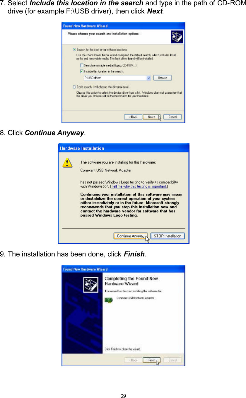
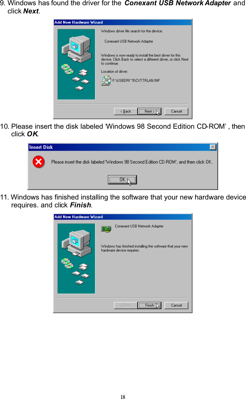
![176. Windows has found the driver for the Conexant USB Network Device. and click Next.7. Select Search for the best driver for your device. [Recommended] and click Next.8. Select Specify a location and use Browse to open the file of F:\USB driver ,click Next.](https://usermanual.wiki/Well-Communication/AWR-8210/User-Guide-368640-Page-18.png)
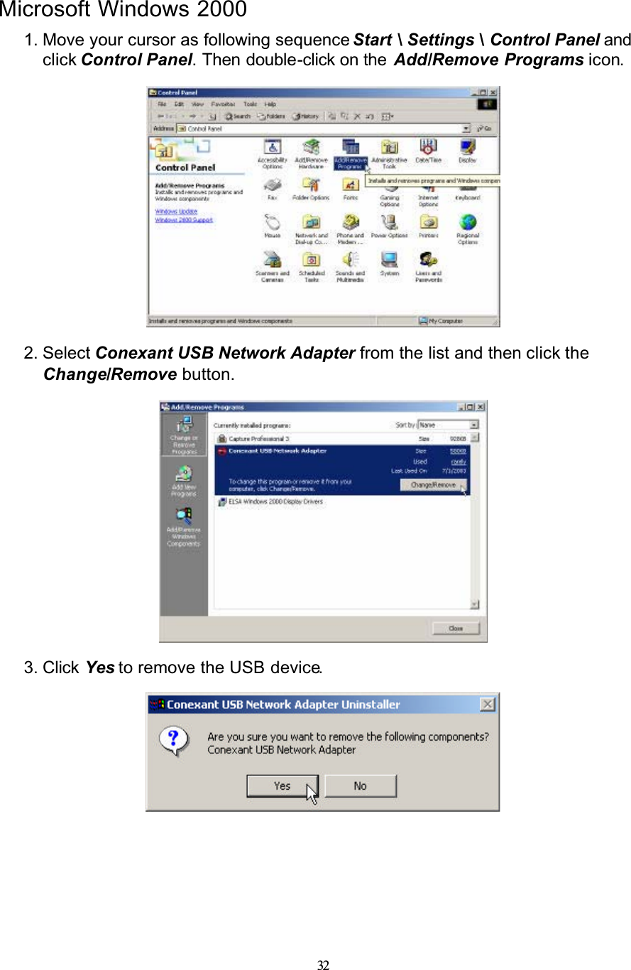
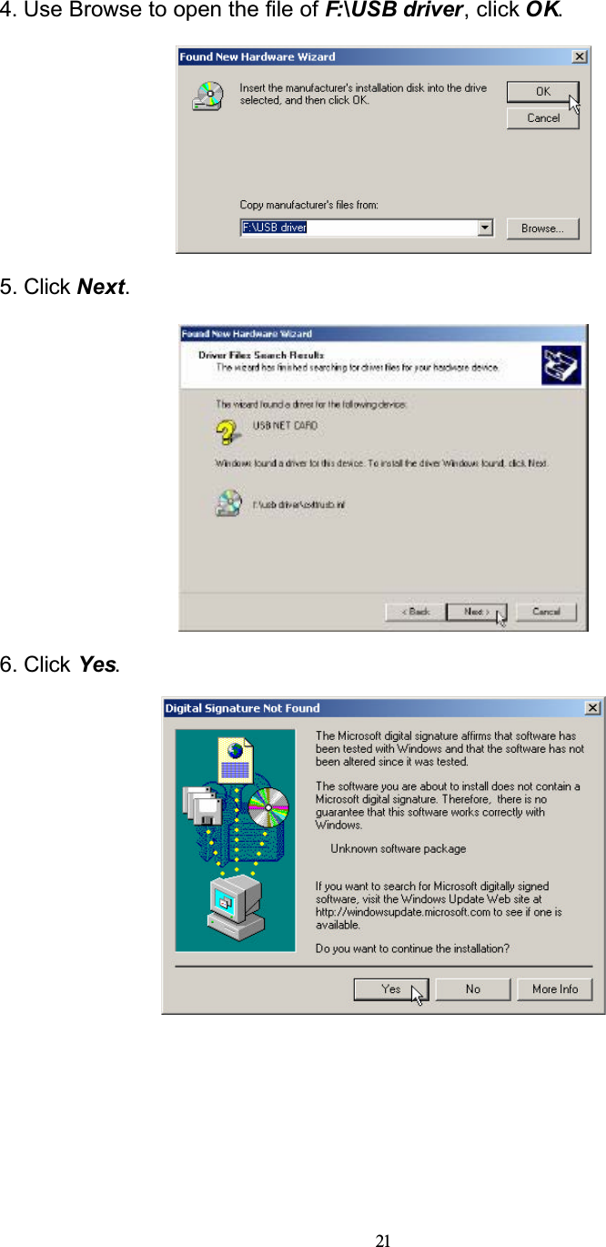
![20Microsoft Windows 20001. Please insert the driver CD into CD-ROM drive and click Next.2. Select Search for a suitable driver for my device [recommended] and click Next.3. Select Specify a location and click Next.](https://usermanual.wiki/Well-Communication/AWR-8210/User-Guide-368640-Page-21.png)
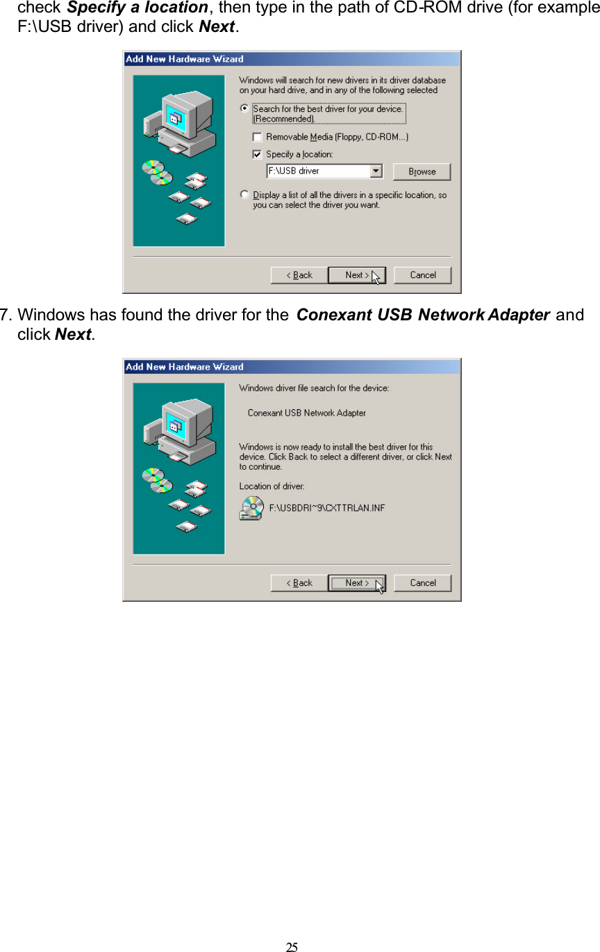
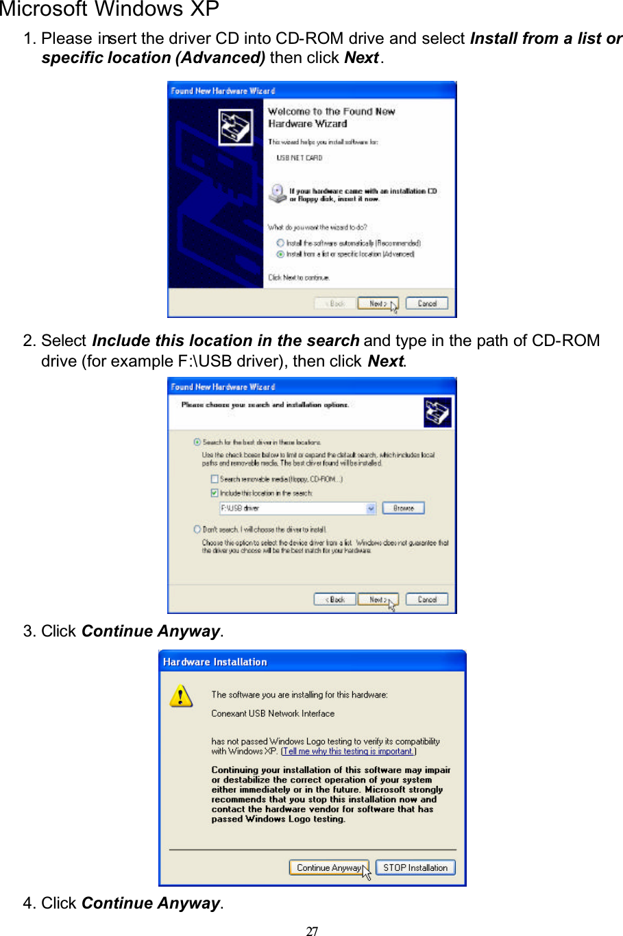
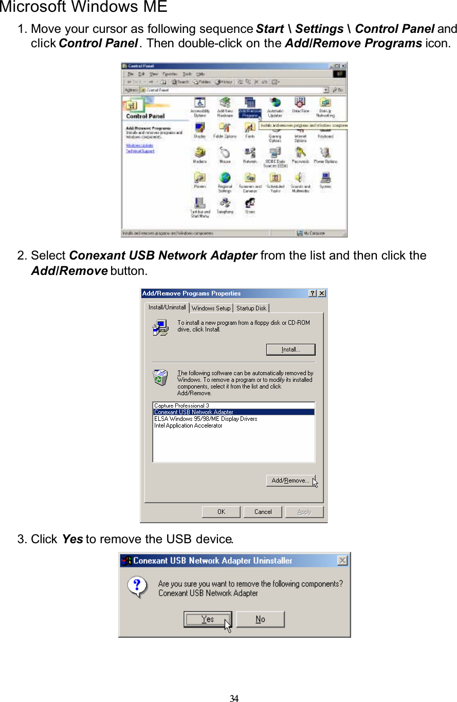
![23Microsoft Windows ME1. Please insert the driver CD supplied when you see the message of USB NET CARD appearing on the screen, select Specify the location of the driver (Advanced), then click Next.2. Select Search for the best driver for your device. [Recommended] and check Specify a location, then type in the path of CD-ROM drive (for example F:\USB driver) and click Next.](https://usermanual.wiki/Well-Communication/AWR-8210/User-Guide-368640-Page-24.png)
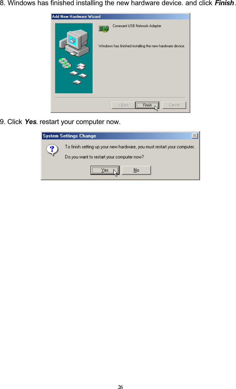
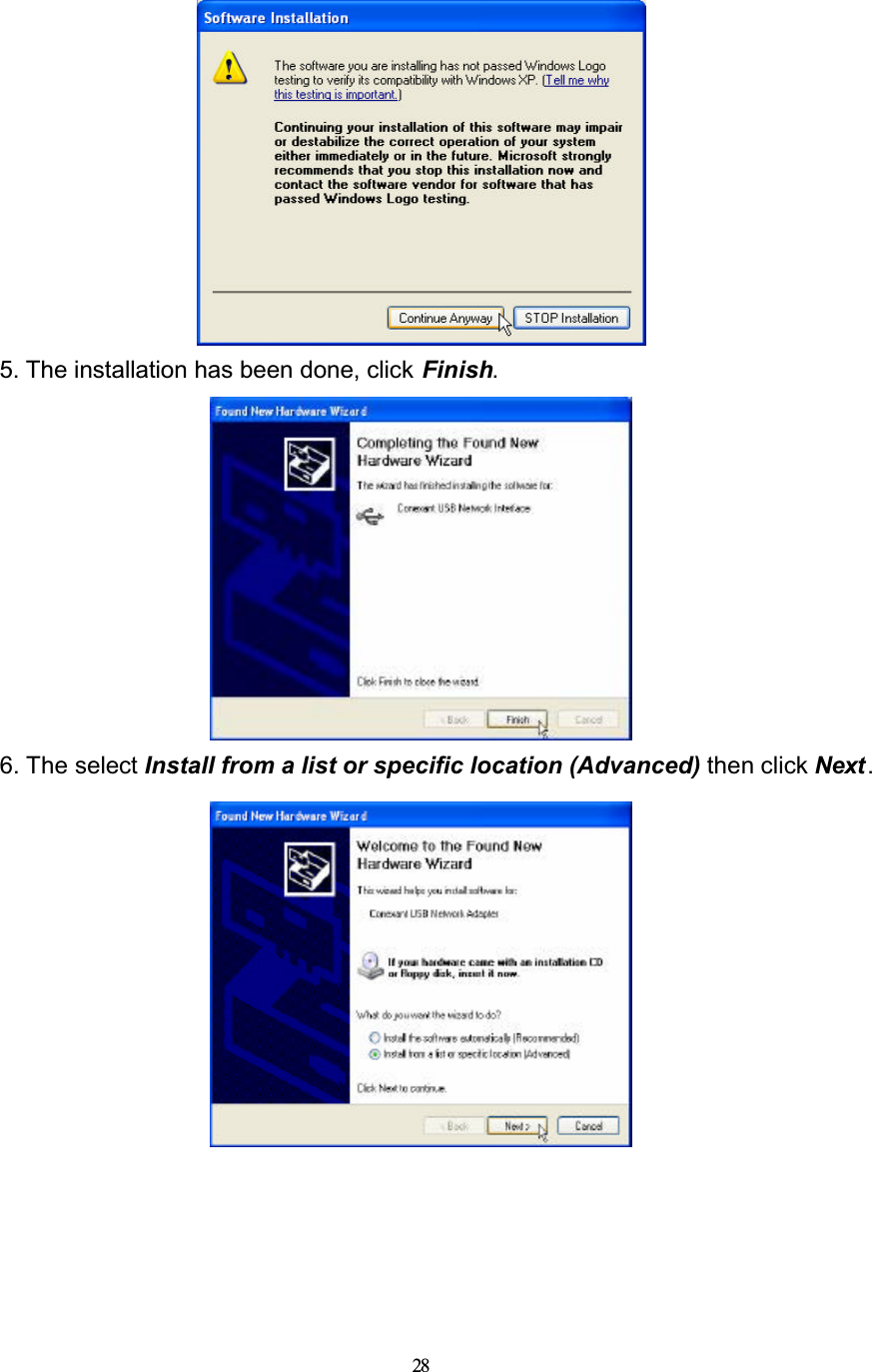
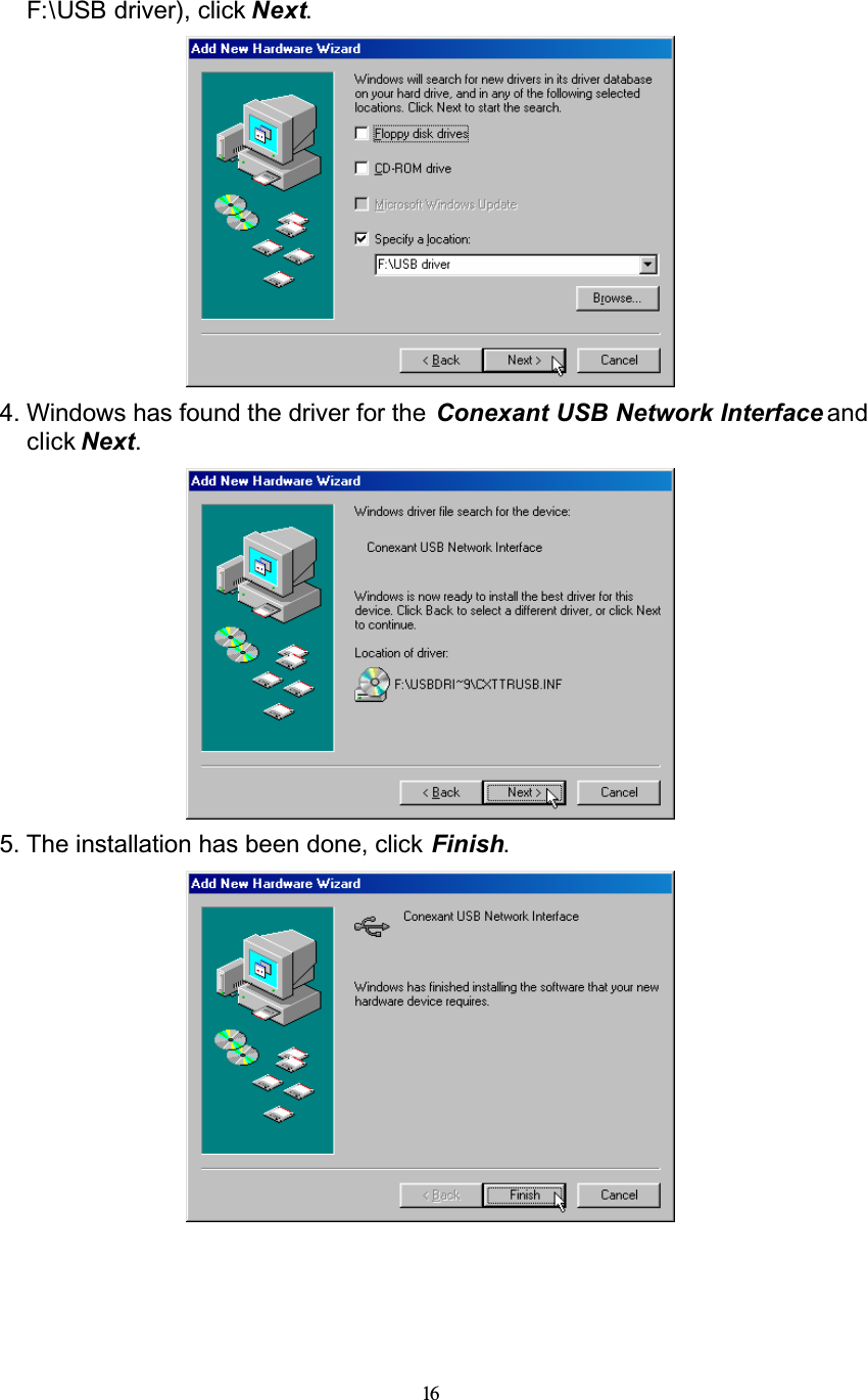
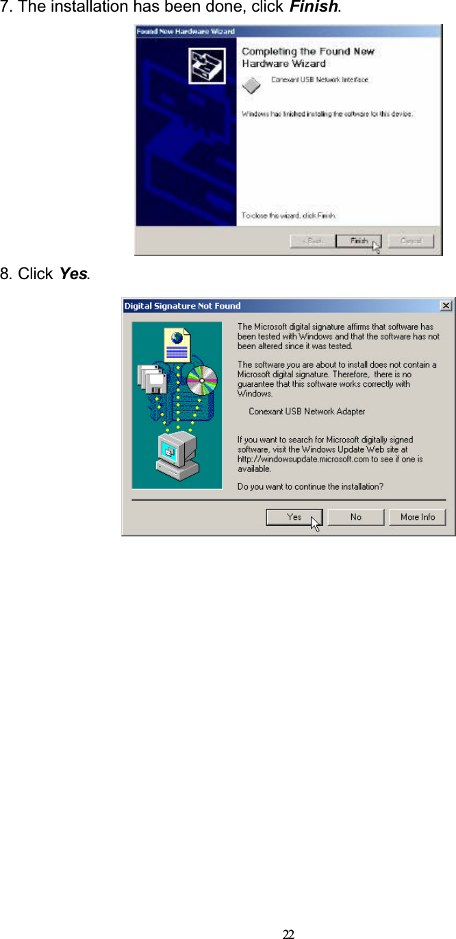
![243. Windows has found the driver for the Conexant USB Network Interface and click Next.4. The installation has been done, click Finish.5. Windows has found the driver for the Conexant USB Network Device. Select Specify the location of the driver (Advanced) and click Next.6. Select Search for the best driver for your device. [Recommended] and](https://usermanual.wiki/Well-Communication/AWR-8210/User-Guide-368640-Page-25.png)