Wellington Drive Technologies SCS1 SCS Connect User Manual
Wellington Drive Technologies Ltd SCS Connect Users Manual
UserManual.wiki
>
Wellington Drive Technologies
>
SCS1 User Manual
Users Manual
Navigation menu
Upload a User Manual
Namespaces
Wiki Guide
HTML
PDF
Info
Views
User Manual
Discussion / Help
Navigation

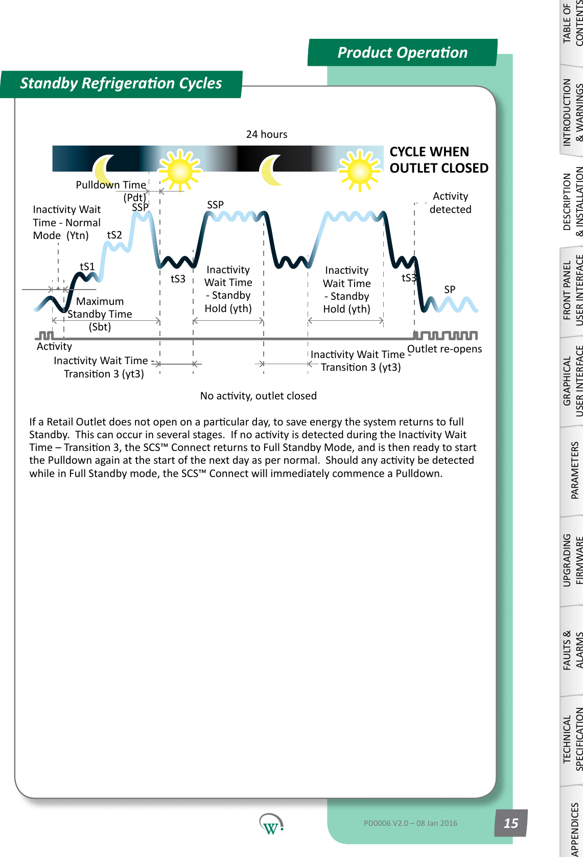
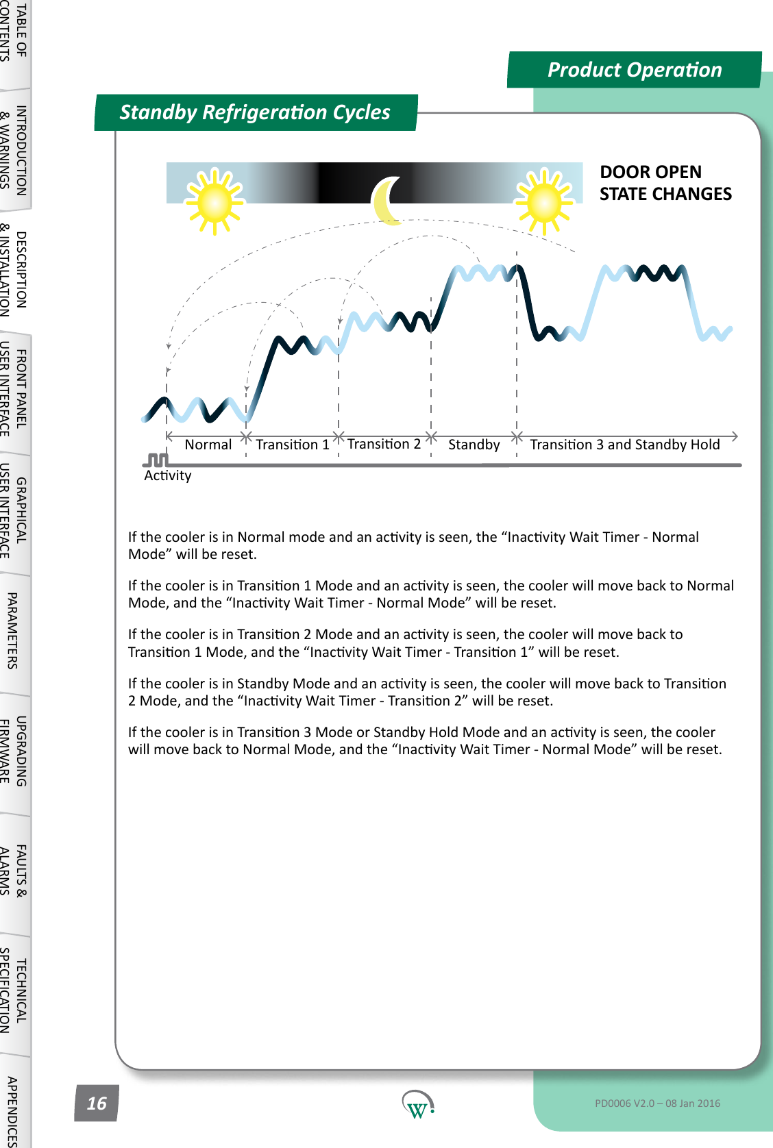
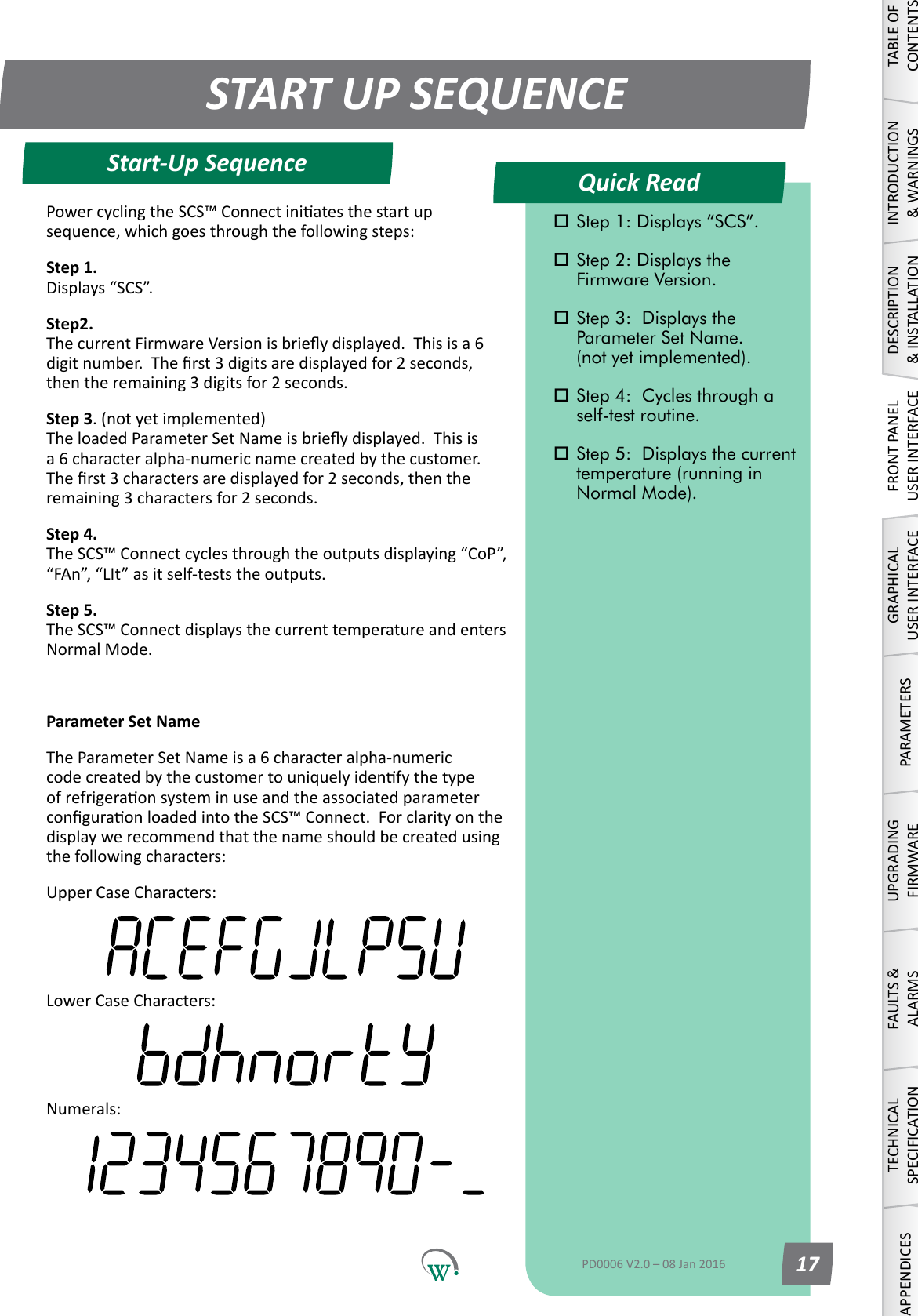
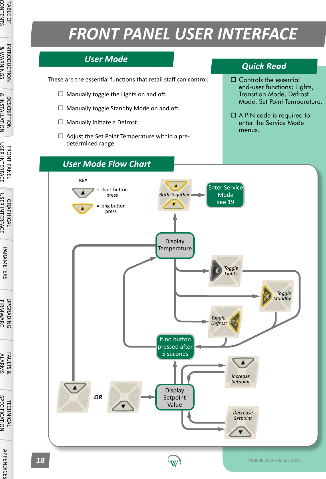
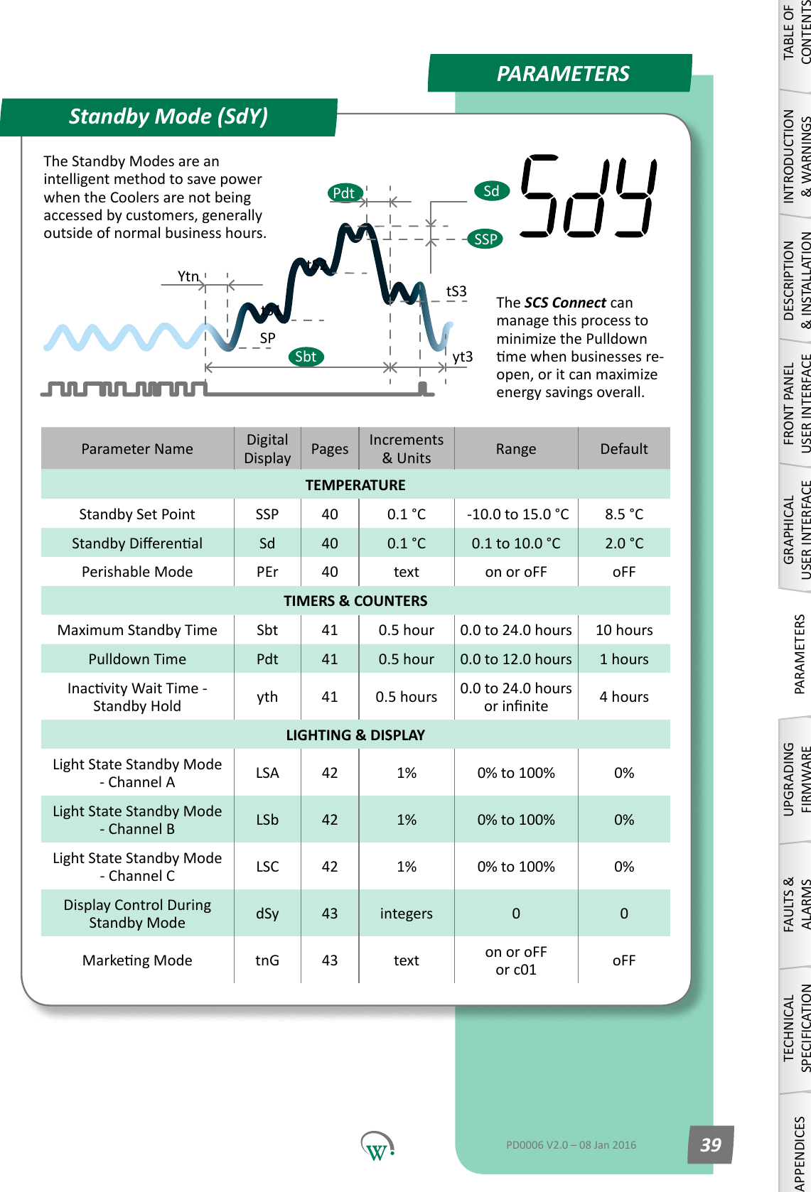
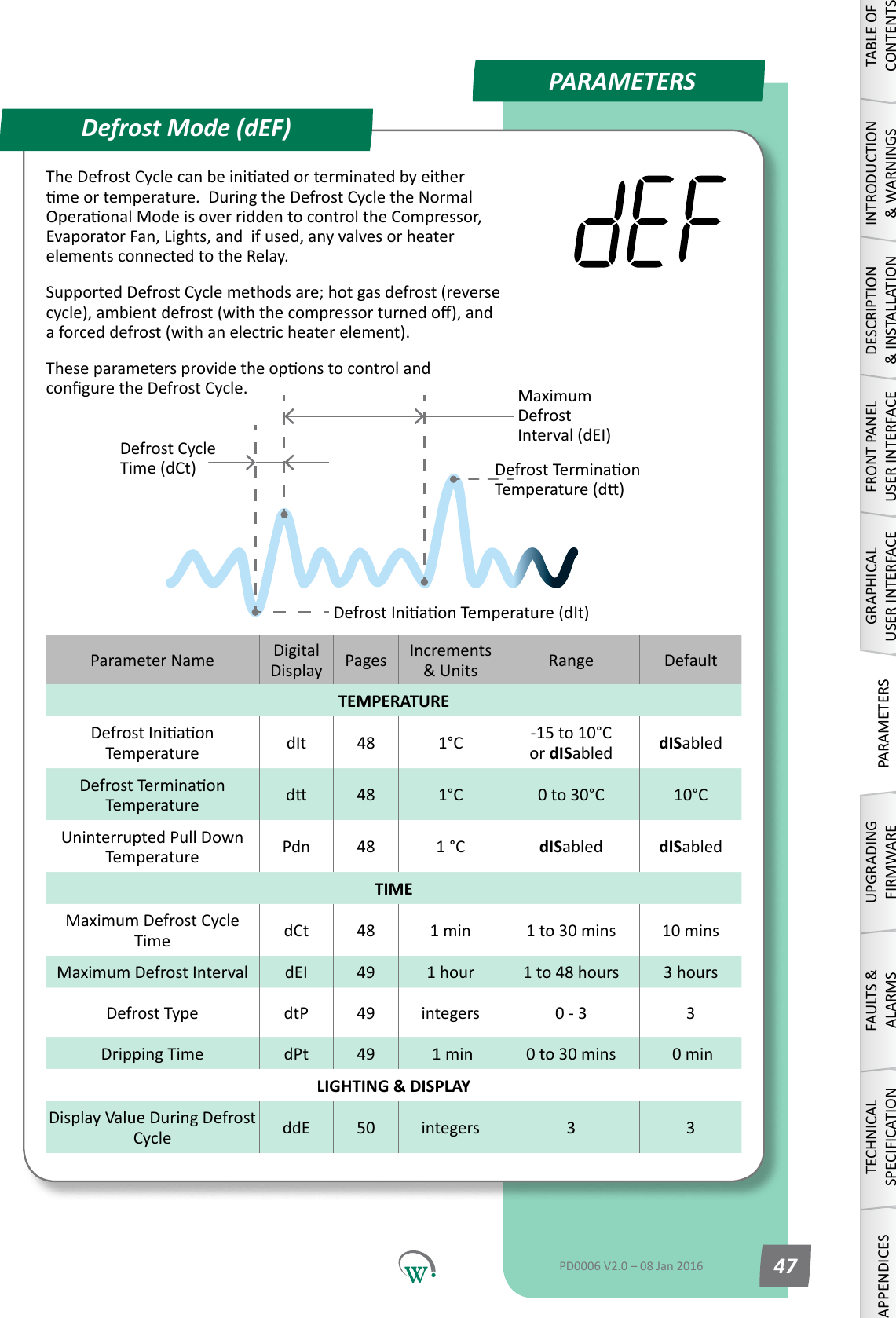
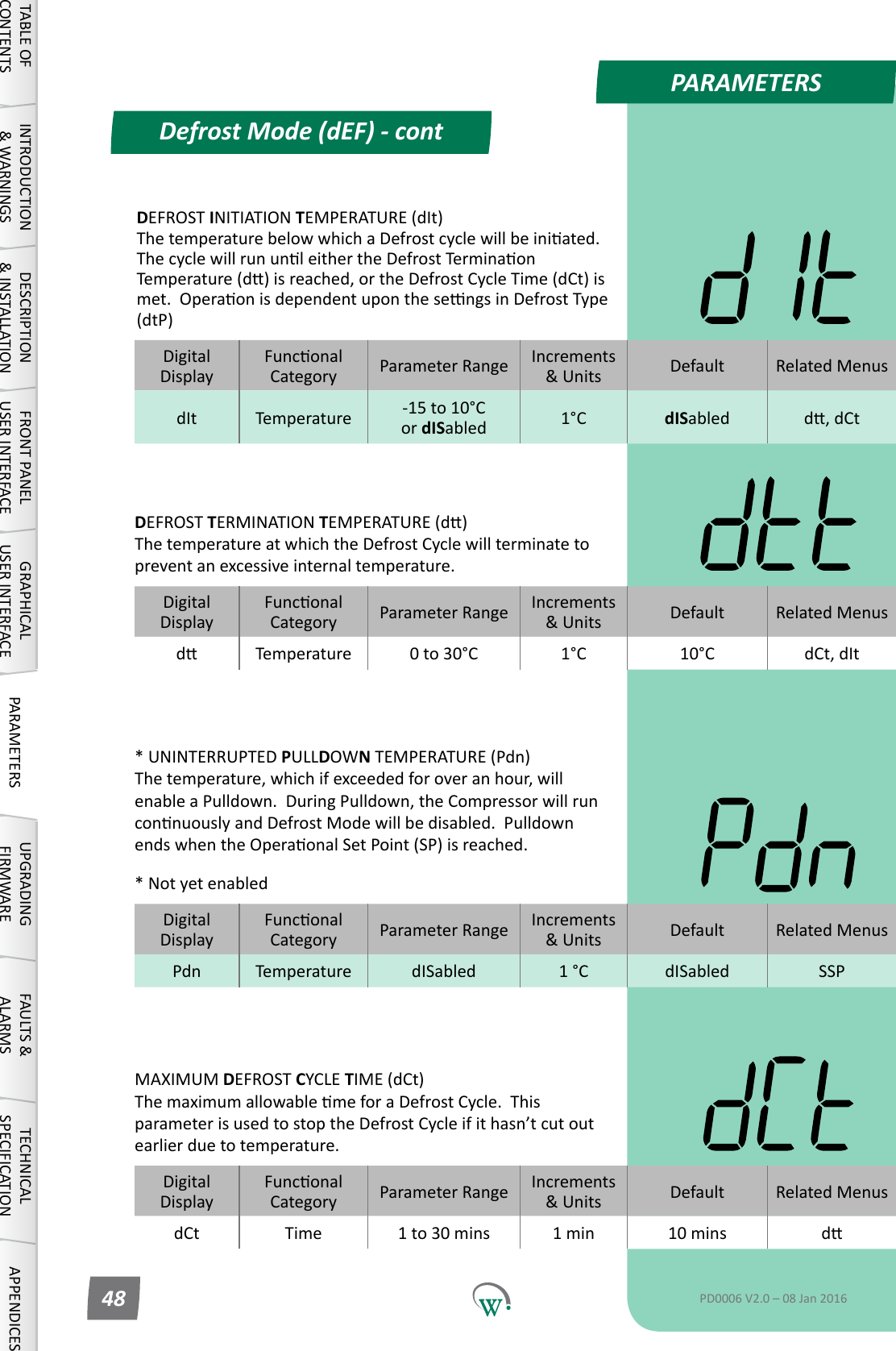
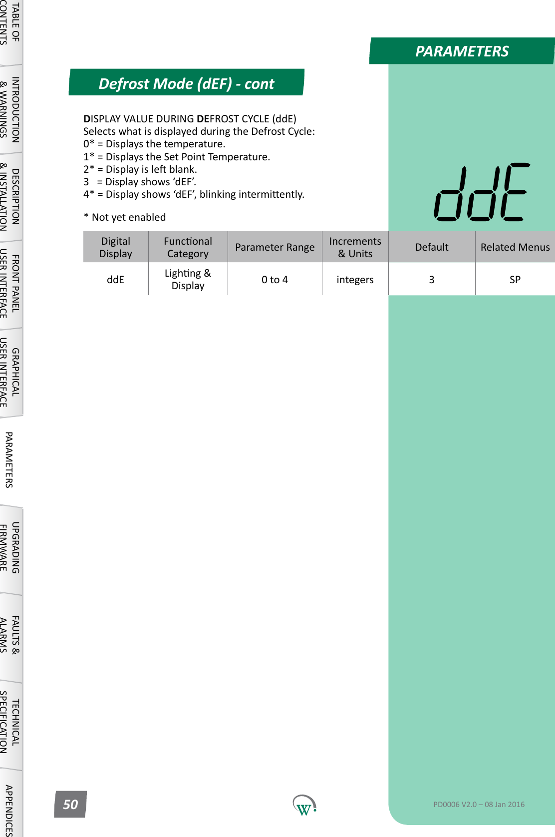
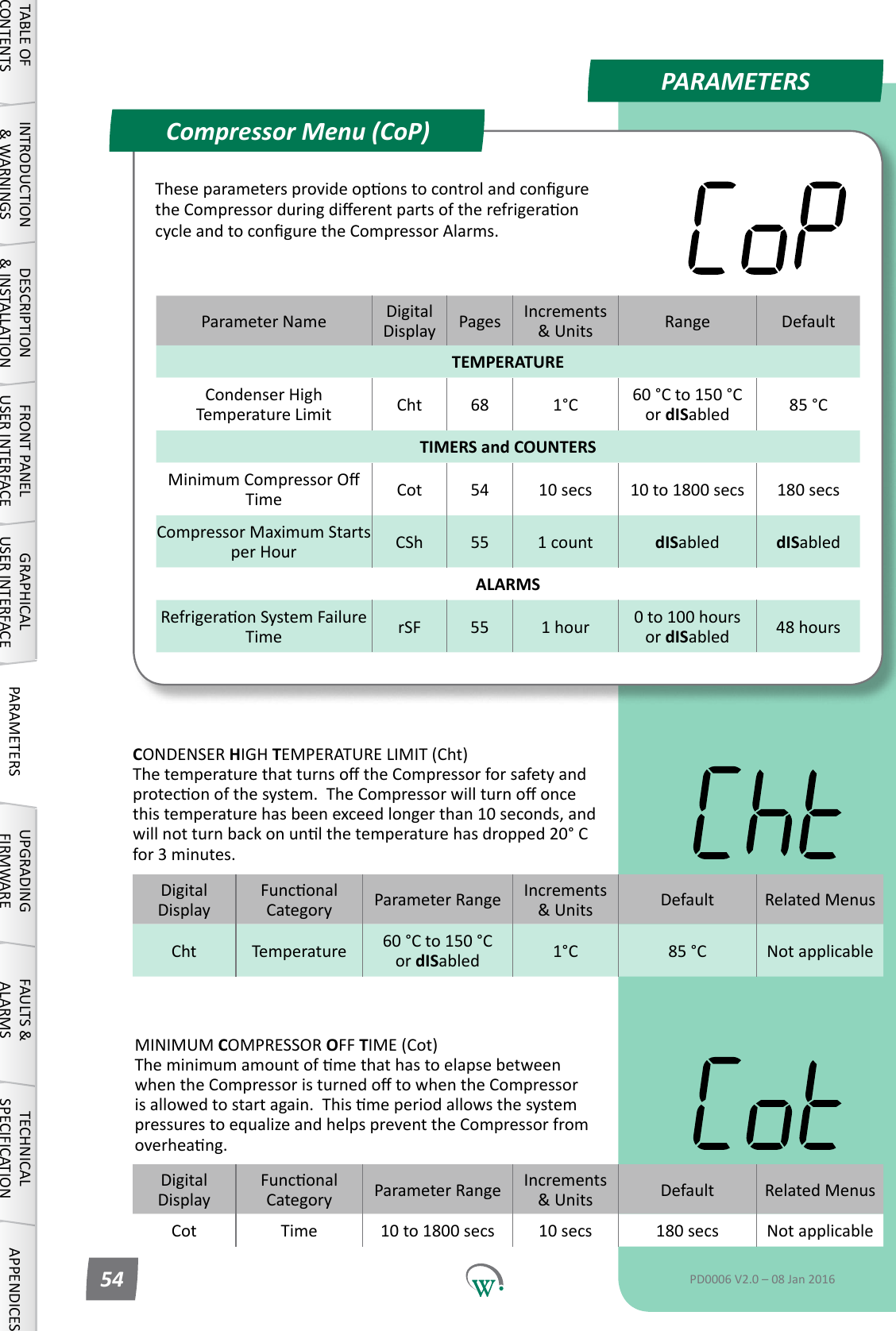
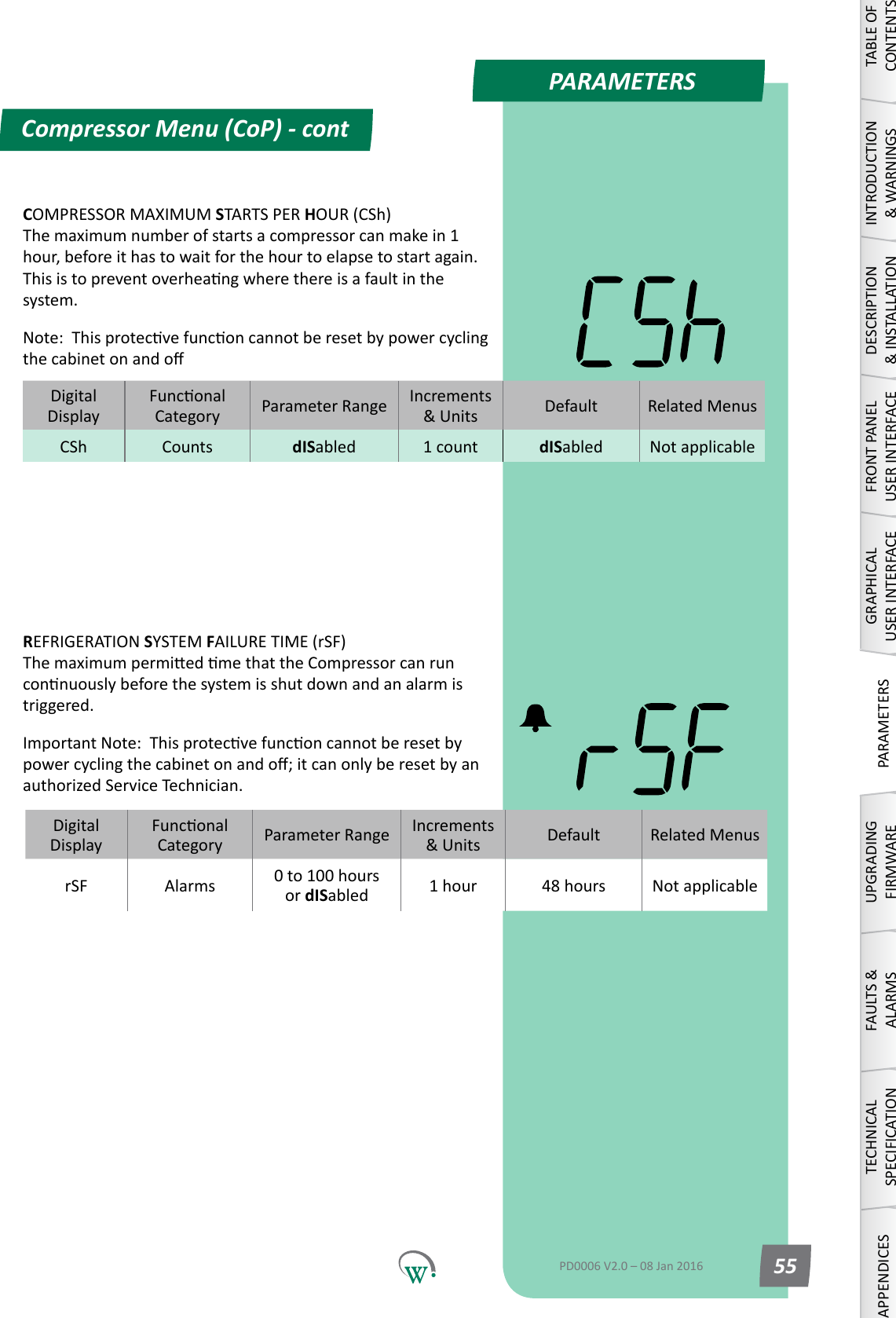
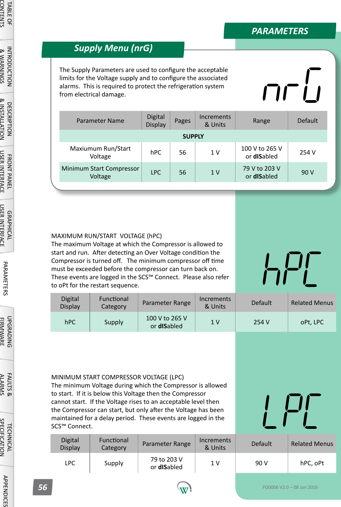
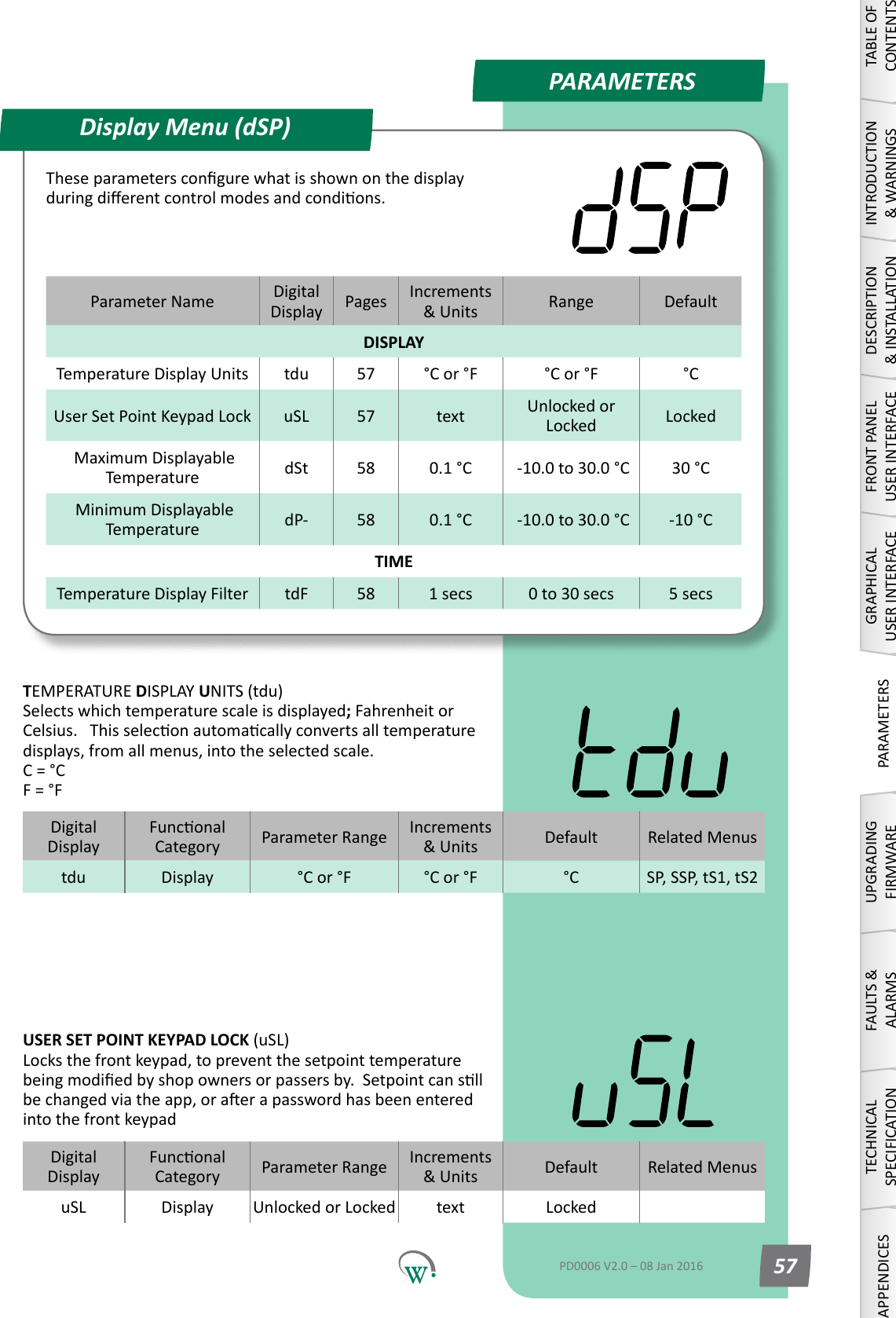
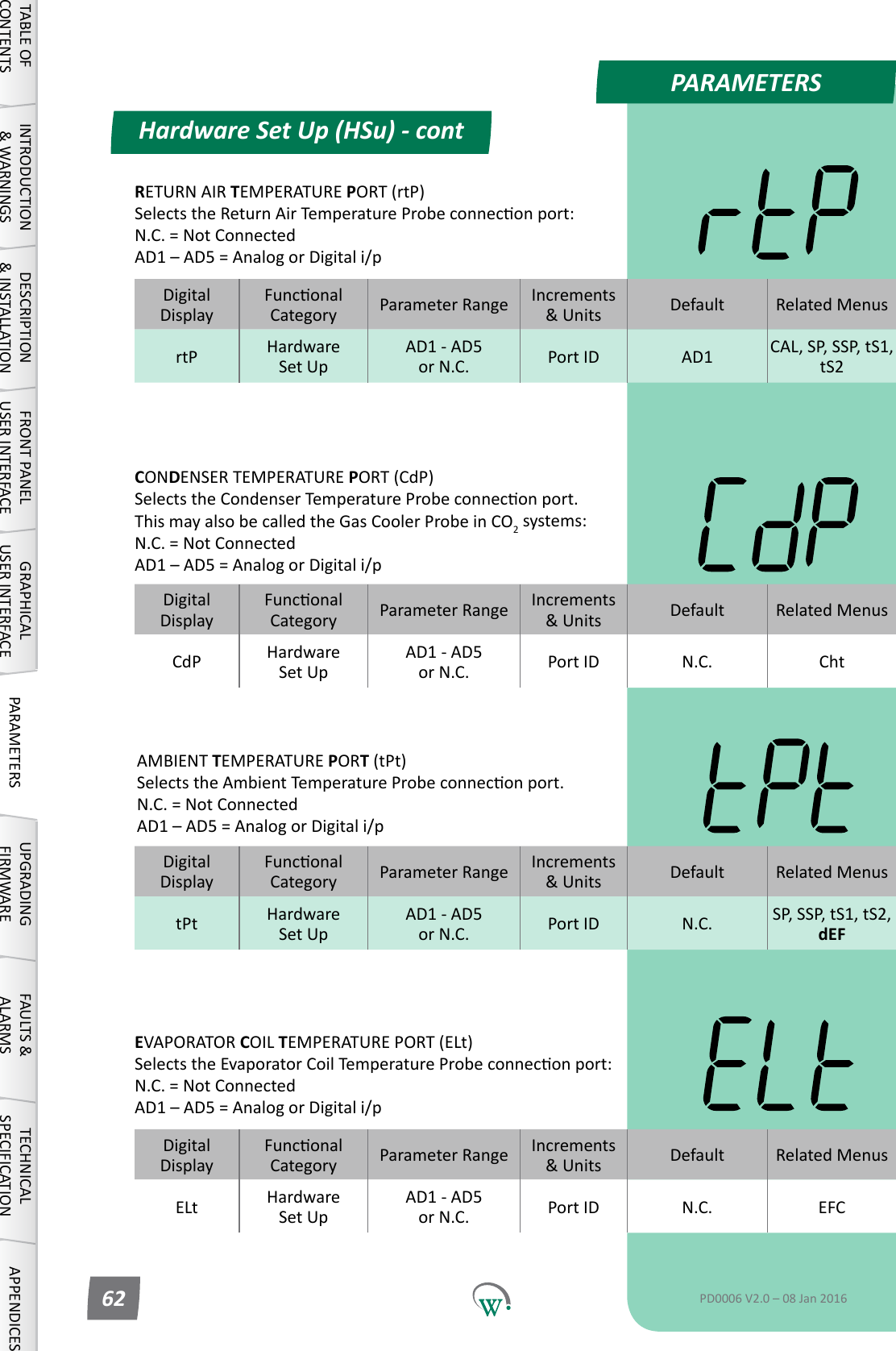
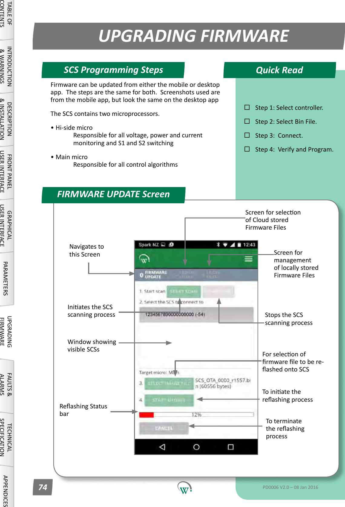
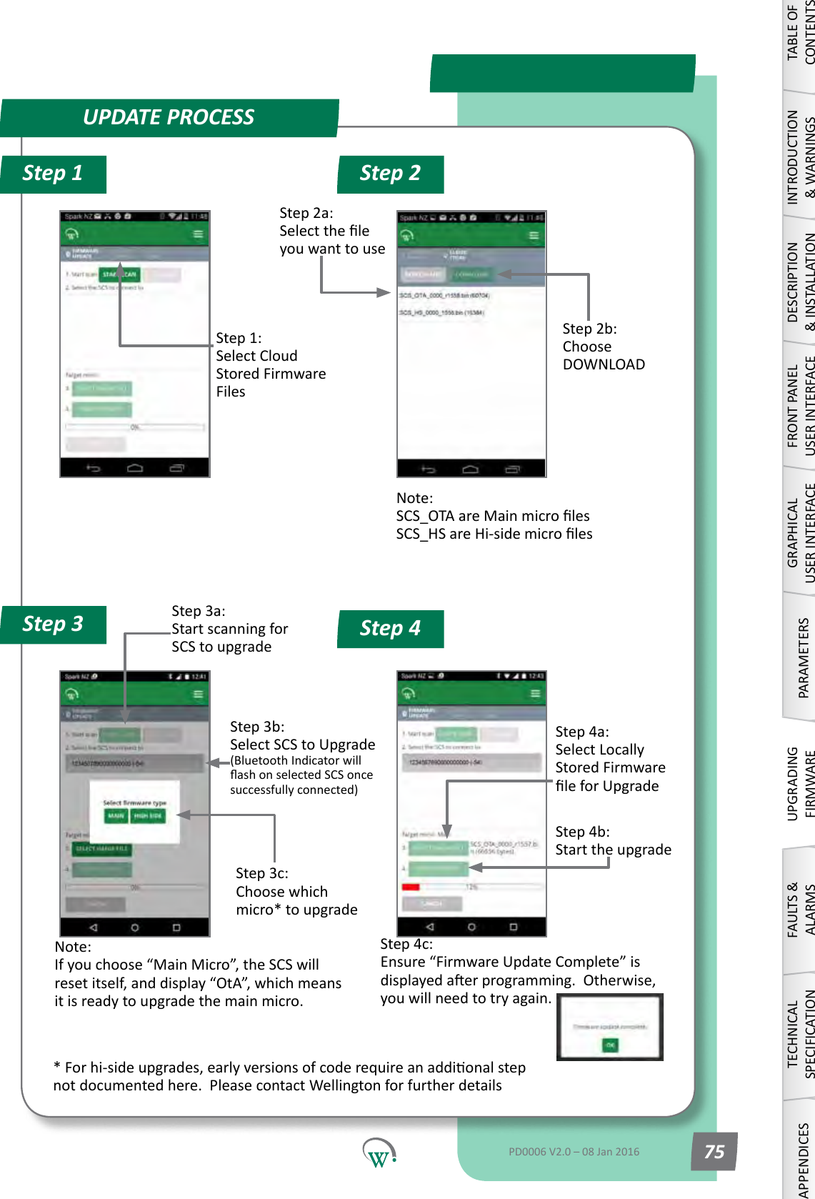
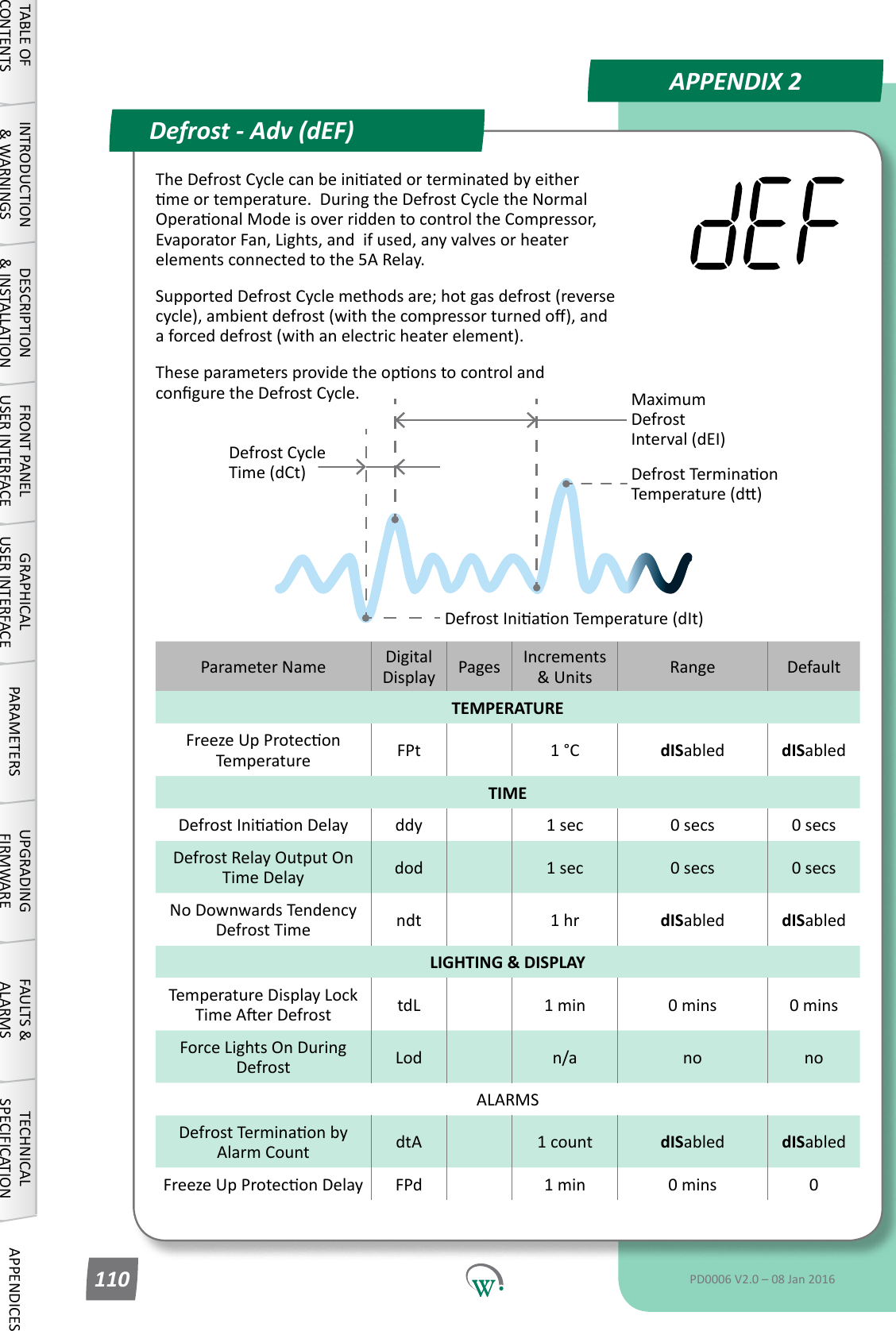
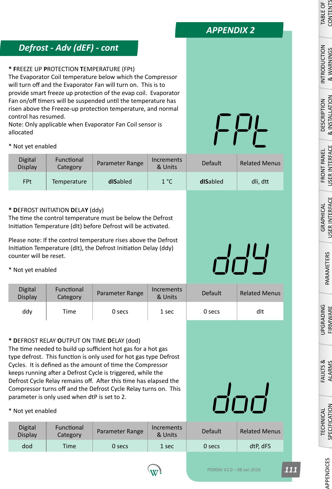
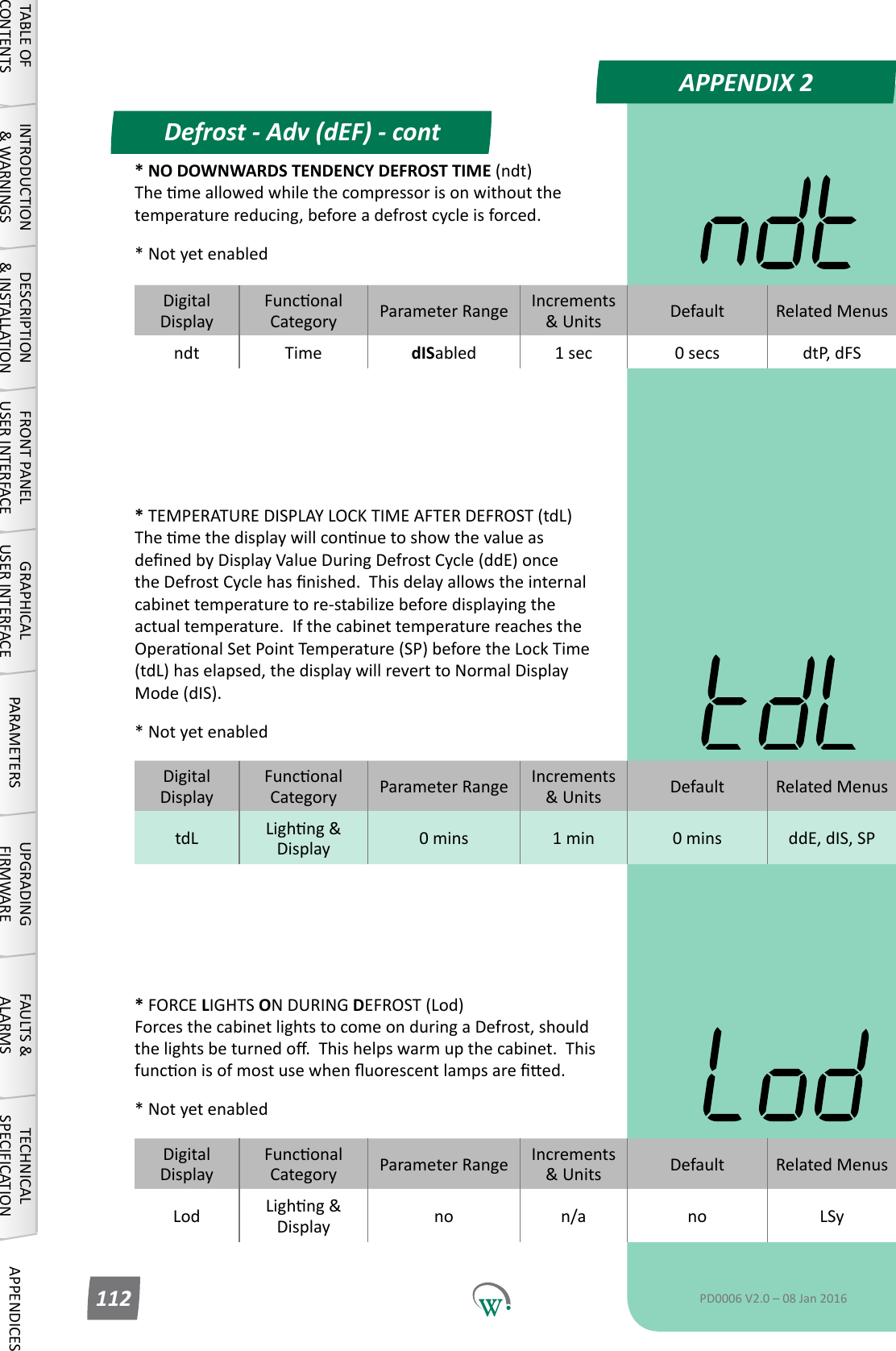
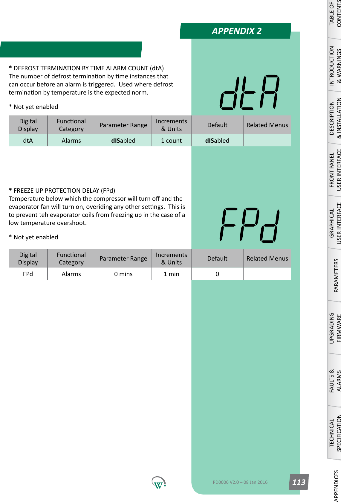
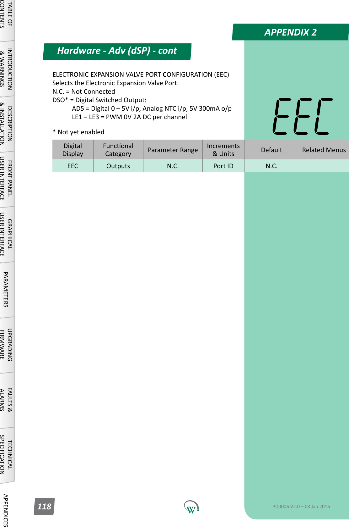
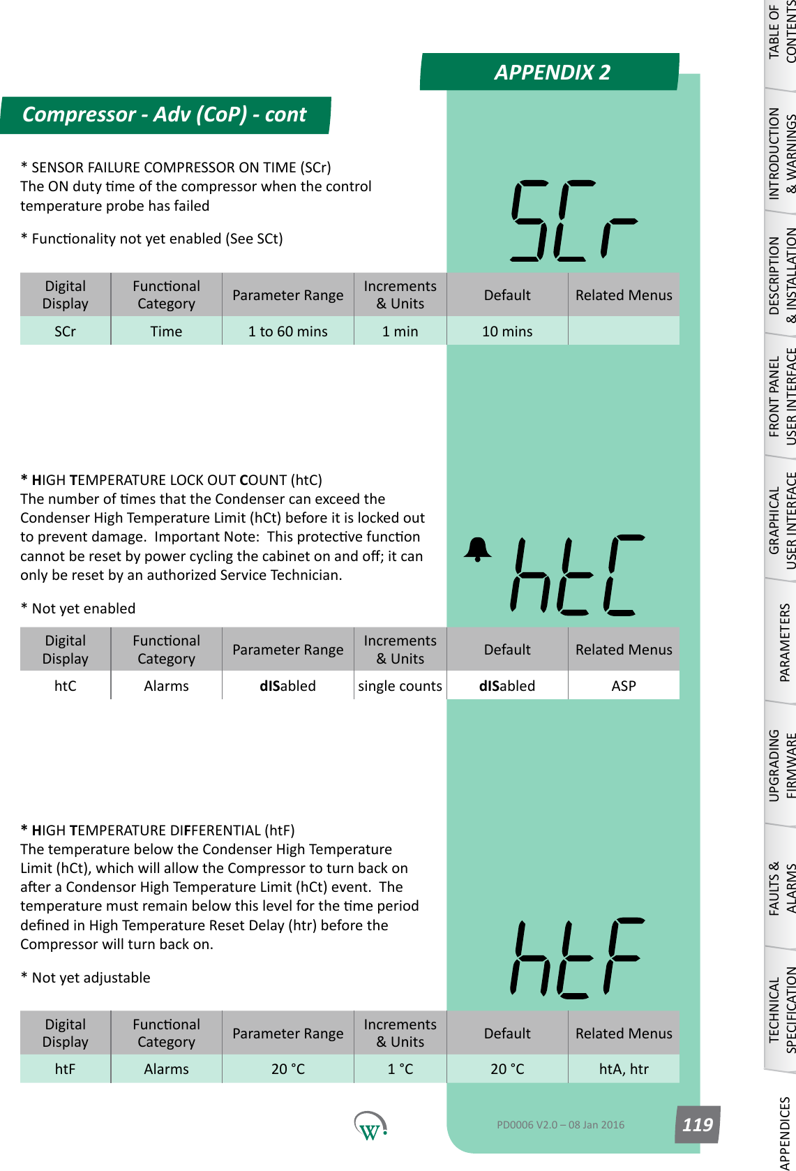
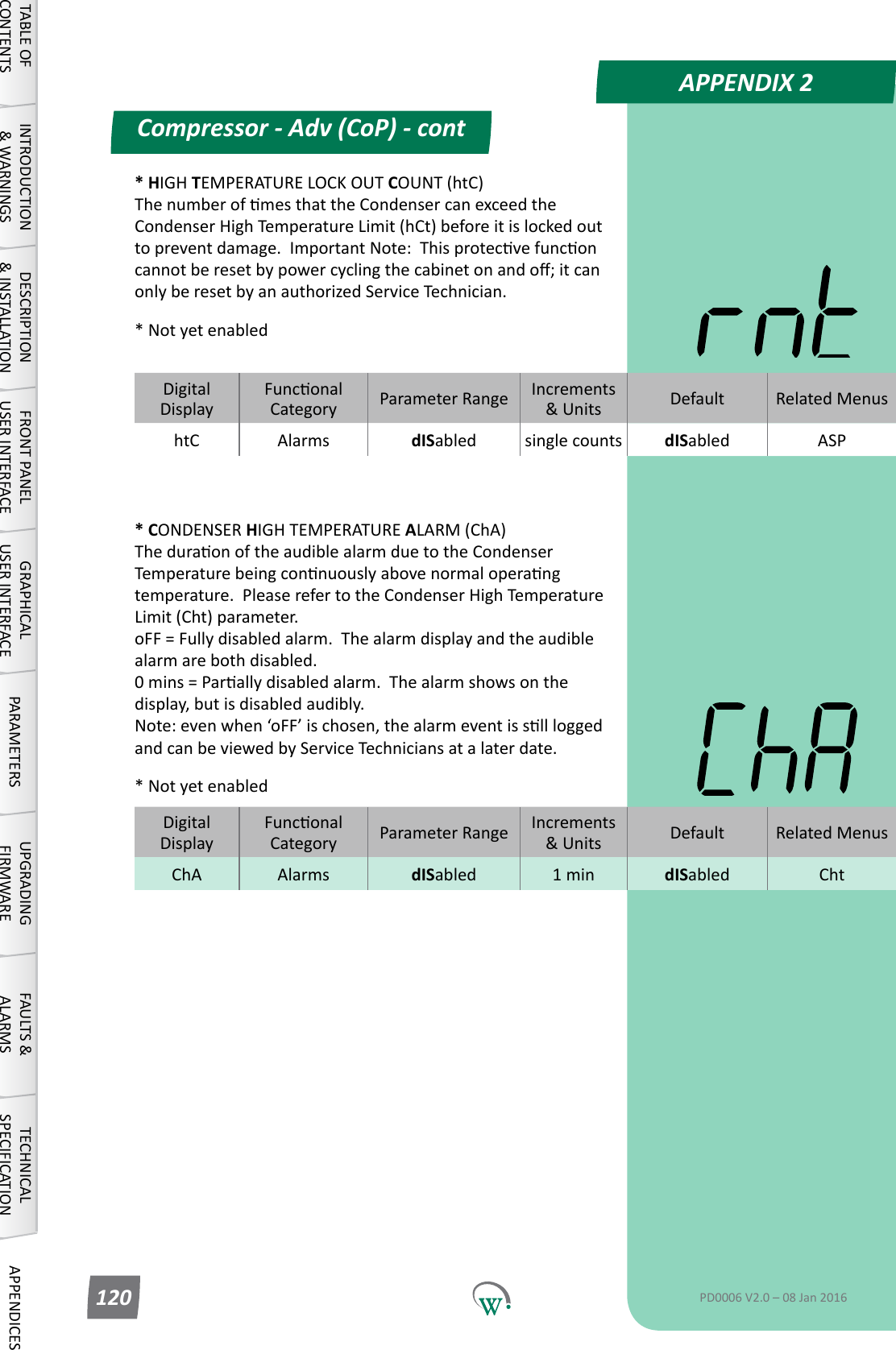
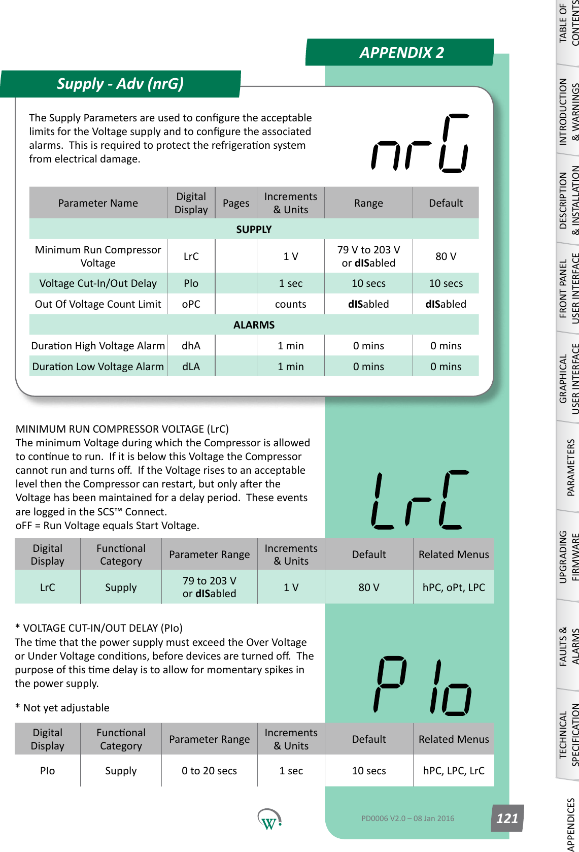
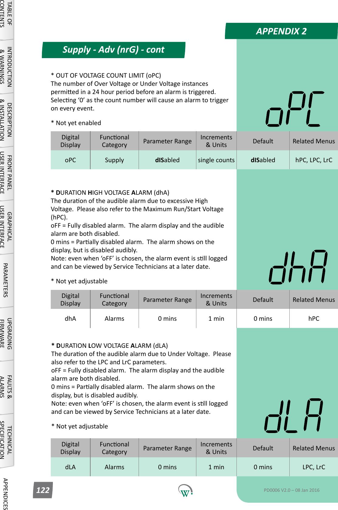
![PARAMETERSDefrost Mode (dEF) - contTABLE OF CONTENTSINTRODUCTION & WARNINGSDESCRIPTION & INSTALLATIONFRONT PANEL USER INTERFACEGRAPHICAL USER INTERFACEPARAMETERSUPGRADING FIRMWAREFAULTS & ALARMSTECHNICAL SPECIFICATIONAPPENDICESPD0006 V2.0 – 08 Jan 2016 49DigitalDisplayFunconalCategory ParameterRange Increments &Units Default Related MenusdEI Time 1 to 48 hours 1 hour 3 hours dCt, dItMAXIMUM DEFROST INTERVAL (dEI) ThemaximumpermiedmebetweenthenishofaDefrostCycle and the start of the next one. This parameter is used to start the Defrost Cycle if it hasn’t started earlier due to temperature.DigitalDisplayFunconalCategory ParameterRange Increments &Units Default Related MenusdtP Time 0 - 3 integers 3 dPt, dFSDEFROST TYPE (dtP) Selects which defrost method is to be used: 0 = Disabled. 1=DefrostCycleusinganelectricheater. [Defrost ON - Evap OFF - Comp/Cond ON] 2*=DefrostCycleusinghotgas(ReverseCycle). 3=DefrostCyclebyturningotheCompressor(AmbientDefrost). [Defrost OFF - Evap ON - Comp/Cond OFF]* Not yet enabledDigitalDisplayFunconalCategory ParameterRange Increments &Units Default Related MenusdPt Time 0 to 30 mins 1 min 0 min dtPDRIPPING TIME (dPt) ThemeneededforexcessmoisturetodripotheEvaporator,tohelppreventfreezeup.Usedforhotgasandelectricheaterdefrostsonly.ThiswaitmeoccursaertheDefrosthasbeenterminatedbyeithermeortemperature,butbeforeexingtheDefrostCycleandreturningtothenon-defrostoperaonalstate.Duringthisme,theEvaporatorFan,CondenserFanandCompressorremaino. 0 = Disabled.](https://usermanual.wiki/Wellington-Drive-Technologies/SCS1/User-Guide-3226762-Page-49.png)