Wellington Drive Technologies SCS1 SCS Connect User Manual
Wellington Drive Technologies Ltd SCS Connect Users Manual
Users Manual
TECHNICAL USER MANUAL
CONNECT

© 2016 Wellington Drive Technologies Limited
Saving Generaon for the Next Generaon
21 Arrenway Drive, Rosedale, Auckland 0632, New Zealand
PO Box 302-533, North Harbour, Auckland 0751, New Zealand
Phone: + 64 9 477 4500, Fax: + 64 9 479 5540,
Email: info@wdtl.com Website: www.wdtl.com

1 TECHNICAL USER MANUAL
3 TABLE OF CONTENTS
4 WARNINGS!
7 INTRODUCTION
8 PRODUCT DESCRIPTION
8 Front Display Panel
9 Rear Connector Panel
10 InstallaonDiagrams
12 WiringDiagrams
13 OperangCycle
17 START UP SEQUENCE
18 FRONT PANEL USER INTERFACE
18 User Mode
19 Service Mode
22 GRAPHICAL USER INTERFACES
23 Authencaon
24 ConnecngtoaDevice
25 ParameterEding
27 PARAMETERS
27 Normal Mode (nrL)
33 Transion1Mode(tn1)
36 Transion2Mode(tn2)
39 Standby Mode (SdY)
44 Transion3Mode(tn3)
47 Defrost Mode (dEF)
51 Door Menu (dor)
54 Compressor Menu (CoP)
56 Supply Menu (nrG)
57 Display Menu (dSP)
59 Hardware Set Up Menu (HSu)
73 LoggingMenu(LoG)
74 UPGRADING FIRMWARE
76 TECHNICAL SPECIFICATIONS
80 GLOSSARY
85 FAULTS AND ALARMS
96 APPENDIX 1
96 Full Parameter List
Quick Read
TABLE OF CONTENTS
TABLE OF
CONTENTS
INTRODUCTION
& WARNINGS
DESCRIPTION
& INSTALLATION
FRONT PANEL
USER INTERFACE
GRAPHICAL
USER INTERFACE
PARAMETERS
UPGRADING
FIRMWARE
FAULTS &
ALARMS
TECHNICAL
SPECIFICATION
APPENDICES
PD0006 V2.0 – 08 Jan 2016 3
Quick Read
WARNINGS!
TABLE OF
CONTENTS
INTRODUCTION
& WARNINGS
DESCRIPTION
& INSTALLATION
FRONT PANEL
USER INTERFACE
GRAPHICAL
USER INTERFACE PARAMETERS UPGRADING
FIRMWARE
FAULTS &
ALARMS
TECHNICAL
SPECIFICATION APPENDICES
Important Do’s and Dont’s:
Do not use water jets on the
rear of the unit. Warning!
Risk of electrocution. If
correctly installed, powerful
water jets may be applied
only to the front of the unit.
Do not drop the SCS
Connect.
There are no serviceable
parts inside the SCS
Connect. Do not open the
housing. Warning! Risk of
electrocution.
PD0006 V2.0 – 08 Jan 2016
4 4
Pleasereadthefollowingwarningstomaintainthesafefuncon
andconnuedperformanceofyourWellingtonDriveTechnologies
Limited SCS™ Connect controller:
Installaon;
InstallaonoftheSCS Connect controller other than in
accordancewiththe“Descripon&Install”seconofthis
manual will invalidate the warranty. The SCS™ Connect must
onlybeinstalledandconguredbytrainedandauthorizedsta.
Washdown;
The front of the unit may be exposed to water jets. Warning!
Therearoftheunitmustnotbeexposedtohighpressure
water jets or temporary submersion, as this will invalidate
thewarranty,andmaydamageelectroniccircuitsleadingto
prematurefailureorunsafeoperaon.Mounngoftheunit
mustbeinaccordancewithorientaonasspeciedinthe
“Descripon&Install”secon.Warning!Riskofelectrocuon.
Chemicals;
The SCS Connectcontroller’shousingismadeofpolycarbonate,
andshouldnotbeexposedtochemicalswhichaackthis
material,asthiswillinvalidatethewarrantyandmaydamage
thehousing,leadingtounsafeoperaon.Warning! Risk of
electrocuon
Temperature;
The SCS Connect controller must only be subjected to
temperaturesasspeciedinthe“TechnicalSpecicaons”
seconofthismanual.Exceedingtheseranges,eitherin
operaon,installaon,transportaon,orstorage,willinvalidate
thewarranty,andmaydamageelectroniccircuitsandhousing
components,leadingtoprematurefailure.
Vibraonandimpact;
The unit MUST be installed in such a way as to be protected
fromimpactinoperaon.Donothitordroptheunit.
Exposuretoimpacts,eitherinoperaon,installaon,
transportaon,orstorage,maydamageelectroniccircuits
andhousingcomponents,leadingtoprematurefailure,and
may cause the SCS Connect controller to become unsafe. Any
impactwhichcausesvisualdamagetothecontrollercasingwill
invalidate the warantee.
Noserviceableparts;
There are no serviceable parts inside the SCS Connect
controller.Donotopenthehousing,exceptfortherearcover,
asdescribedinthe“DescriponandInstallaon”seconof
thismanual.Openingoftheelectronicshousing,alterang
ormodifyingtheSCS Connect controller will invalidate the
warrantyandcancauseriskofelectrocuon.
Quick Read
Warnings - cont
TABLE OF
CONTENTS
INTRODUCTION
& WARNINGS
DESCRIPTION
& INSTALLATION
FRONT PANEL
USER INTERFACE
GRAPHICAL
USER INTERFACE
PARAMETERS
UPGRADING
FIRMWARE
FAULTS &
ALARMS
TECHNICAL
SPECIFICATION
APPENDICES
Do not run power and
signal cables together in the
same conduit. Warning!
Risk of electrocution.
Do not connect the SCS
Connect controller to the
incorrect voltage supply.
Ensure phase and relay
terminals are correctly
crimped. Risk of re.
PD0006 V2.0 – 08 Jan 2016 5
Thefollowingpartsareconsideredtobesubjecttonormal
wear and tear, and as such are not covered by warranty
•Scratchesandothervisualdamagetofrontpanel
Voltages;
The SCS Connect controller must only be connected to
powersupplieswhichcomplywiththeacceptablevoltage
rangesspeciedinthe“TechnicalSpecicaon”seconof
thismanual.Connecontosupplyvoltagesoutsideofthese
rangescandamageelectricalcircuits,leadingtopremature
failure, and may cause the SCS Connect controller to
become unsafe. All SCS Connect controller’s ship from the
factorywithvoltagelimitsenabled.Disablingthisprotecon
invalidatesanywarrantyduetoincorrectvoltages.
MaximumvoltagesareloggedbytheSCS Connect controller.
Voltageuctuaonsandsurges;
SCS Connectcontrollerhassurgeproteconasspecied
inthe“TechnicalSpecicaon”seconofthismanual.
Exposuretosurgevoltagesoutsidetheselimits,or
excessivelyrepeatedsurgeswithintheselimits,maycause
damagetoelectricalcircuits,leadingtoprematurefailure.
Failureduetoexcessivesurgevoltagesisnotcoveredby
warranty.
Currents;
SCS Connect controller outputs should not be connected to
shortcircuitsortoloadswhichexceedthecurrentsspecied
inthe“TechnicalSpecicaon”seconofthismanual.
Doingsomaycausethecontrollertofailprematurelyor
immediately,andpossiblytodamagetheconnectedload.
Connecontoincorrectloadsvoidsthewarranty.
Phaseandrelayterminalsmaycarrycurrentshighenough
tooverheatcableterminaons,ifthesearenotcorrectly
speciedandcrimped.Thismaycauseriskofelectrocuon
orre.Caremustbetakentoensurethatcablesand
terminaonsaresafelyterminated.
Segregaonofpowerandsignalcabling;
Correctsegregaonofpowerandsignalcablingmustbe
followed.Donotrunpowerandsignalcablestogetherin
thesameconduit.Induconfrompowercablesmaycorrupt
datasignals,leadingtoincorrectoperaon.
Consequenalfailures;
SCS Connect controller includes features to protect both
itself and connected components in the event of a failure.
However failure of connected components may cause
damagetotheSCS Connect controller, and failure of the
SCS Connectcontrollermaycausedamagetoconnected
components.Cricalorvulnerablecomponentsshould
beprotectedindependentlyagainstfailure.SCSConnect
controllerisnotwarrantedagainstdamagecausedbyorto
other components.
Quick Read
Warnings - cont
TABLE OF
CONTENTS
INTRODUCTION
& WARNINGS
DESCRIPTION
& INSTALLATION
FRONT PANEL
USER INTERFACE
GRAPHICAL
USER INTERFACE PARAMETERS UPGRADING
FIRMWARE
FAULTS &
ALARMS
TECHNICAL
SPECIFICATION APPENDICES
The SCS Connect controller
must only be used for the
purposes described in this
manual.
The SCS Connect controller
must not be disposed off
in municipal collections;
it must be disposed off
through an approved
e-waste collection point.
The design and specication
of the SCS Connect
controller is subject to
change without warning.
PD0006 V2.0 – 08 Jan 2016
6
Fitforpurpose;
The SCS Connect controller must only be used for the
purposeandfunconsdescribedinthismanual.While
WellingtonDriveTechnologiesLimitedmayprovide
technicalsupportonsuitableapplicaonsandconguraon
of the SCS Connectcontroller(wheresucharelaonship
may exist), no liability, responsibility or risk is accepted in
determiningiftheSCS Connectcontrolleristforpurpose
foranyparcularapplicaon.Aseachdierentapplicaon
requiresadierentconguraonofcontrollingparameters,
noliability,responsibilityorriskisacceptedbyWellington
DriveTechnologiesLimitedforthecorrectoperaonal
funconofanyparcularinstallaonorconguraon.
Connuousdevelopment;
WellingtonDriveTechnologiesLimitedundertakesto
connuouslydevelopandimproveproductsandservices.
ThedesignandspecicaonfortheSCS Connect controller
issubjecttochangewithoutwarning.Thecontentsofthis
manualaresubjecttochangewithoutwarning.While
everyendeavourismadetoensurethatallspecicaons
anddocumentsarecurrentandcomplete,WellingtonDrive
TechnologiesLimitedacceptsnoliability,responsibilityor
riskduetoomissionsorchangescausedbyconnuous
improvementanddesignchanges.Usersofthismanual
should verify that they have the current released version
(publishedontheWellingtonDriveTechnologieswebsite
www.wdtl.com)beforeproceeding.
Correctdisposal;
The SCS ConnectcontrollerissubjecttoEUDirecve
2002/96/EC (WEEE) for e-waste. It may also be subject to
othernaonallegislaonforthesafedisposalofe-waste.
The SCS Connectcontrollermustnotbedisposedoin
municipalcollecons;itmustbedisposedothroughan
approvedWEEEcolleconpoint.Alternavely,theSCS
Connectcontrollermaybereturnedtoanauthorized
WellingtonDriveTechnologiesLimiteddistributorattheend
ofitsworkinglife.Penalesmaybeapplicableforincorrect
disposal,asspeciedbynaonallegislaon.Thecircuit
boardmaycontainhazardoussubstanceswhichcouldaect
healthandtheenvironmentifdisposedoincorrectly.The
SCS ConnectcontrollercomplieswithEUDirecve2002/95/
EC (RoHS).
Quick Read
INTRODUCTION
TABLE OF
CONTENTS
INTRODUCTION
& WARNINGS
DESCRIPTION
& INSTALLATION
FRONT PANEL
USER INTERFACE
GRAPHICAL
USER INTERFACE
PARAMETERS
UPGRADING
FIRMWARE
FAULTS &
ALARMS
TECHNICAL
SPECIFICATION
APPENDICES
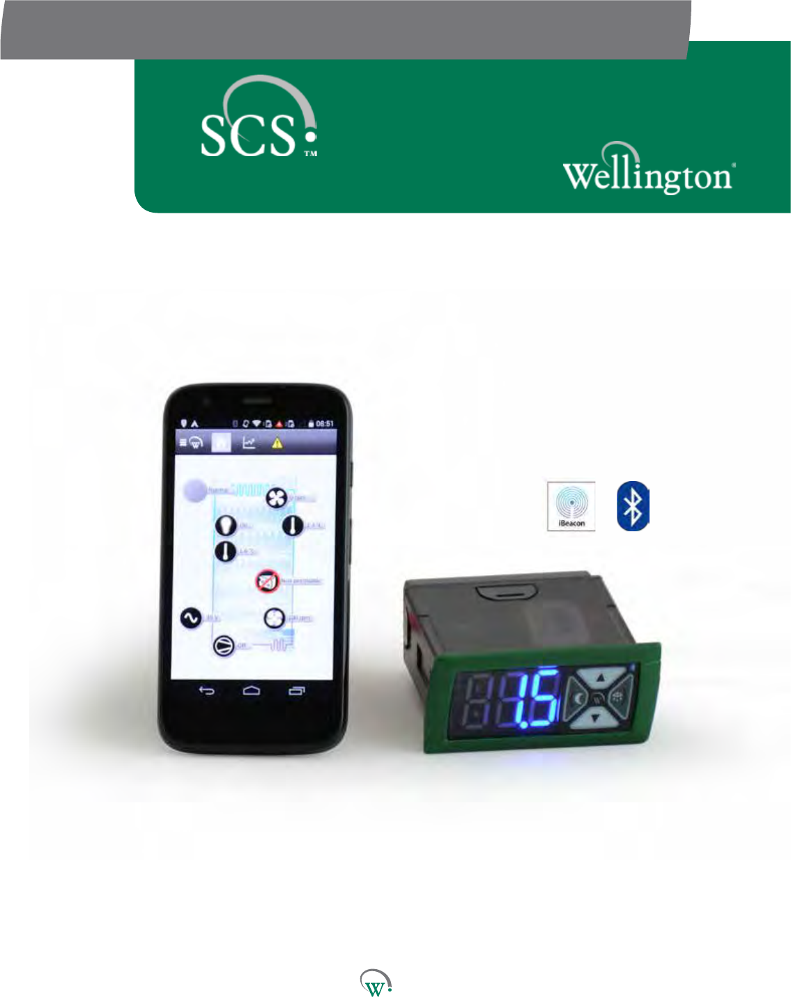
Highly exible and
congurable
Denable levels of control
Mobile app with intuitive
touch screen interface
Wireless data logging and
diagnostic control
Compact size
Sealed
Customized branding
available
PD0006 V2.0 – 08 Jan 2016 7
The SCS ConnectcontrollerbyWellingtonisanelectronic
refrigeraoncontrolunitdesignedtoprovideaveryhighlevelof
exibilityformanufacturersofrefrigeraonunits.
Theinterfacesystempermitsdierentgroupsofuserstohave
dierentlevelsofcontrol,basedupontheirlevelsofexperseand
their actual control needs.
AuniquefeatureisamobileappthatgivesauthorizedService
Techniciansfullwirelessaccesstodatalogginganddiagnosc
control.
The SCS Connectcontroller’shousingmeetsindustrybenchmarks
forcompactsizeandexceedsbenchmarksforsealingatthe
front face. The appearance of the SCS Connect controller can be
customizedtosuitthebrandrequirementsofendcustomers.
10
11
1 2 3 4 5
6
78
9
10
11
1
2
3
4
5
6
7
8
9
Quick Read
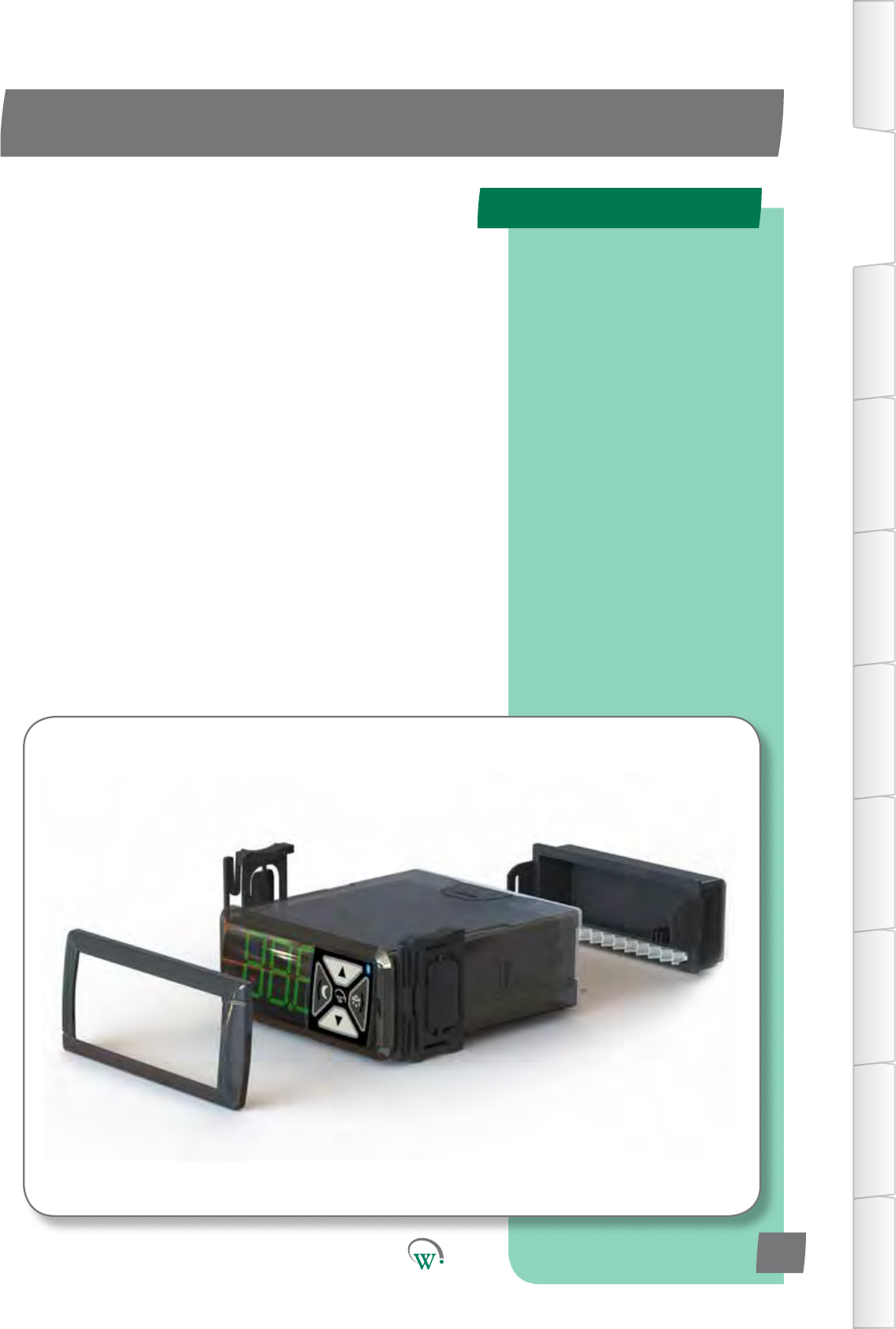
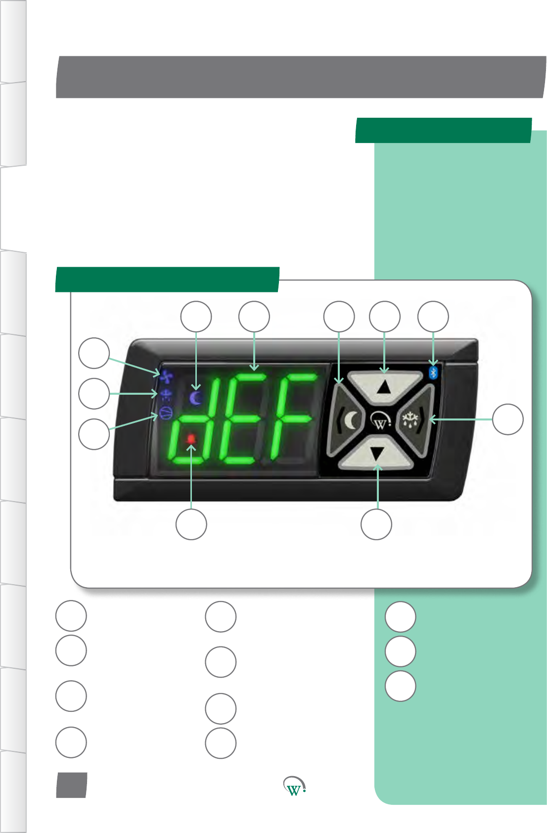
PRODUCT DESCRIPTION
Front Display Panel
TABLE OF
CONTENTS
INTRODUCTION
& WARNINGS
DESCRIPTION
& INSTALLATION
FRONT PANEL
USER INTERFACE
GRAPHICAL
USER INTERFACE PARAMETERS UPGRADING
FIRMWARE
FAULTS &
ALARMS
TECHNICAL
SPECIFICATION APPENDICES
Three main feature
locations:
Front Display Panel
Rear Connector Panel
Housing Installation
Features
PD0006 V2.0 – 08 Jan 2016
8
NightModeIndicator
(seepage18)
ThreeDigitLED
Display
Back/AbortBuon
(seepage18)
NightModeBuon
(seepage18)
UpBuon
(seepage18)
Bluetooth® Wireless
Indicator
(seepage22)
DefrostModeBuon
(seepage18)
Next/EnterBuon
(seepage18)
DownBuon
(seepage18)
Alarm Indicator
(seepage85)
Compressor Indicator
(seepage54)
Defrost Mode Indicator
(seepage68)
Fan Indicator
(seepage30)
The SCS Connectcontrollerconsistsofthreemaingroupsof
features:
The Front Display Panel with the user interface controls.
The Rear Connector Panel where the input and output
cables are connected.
TheMainHousingwhichincludesthemounngclips,
gasketandfaceplatetrimusedforinstallaon.
IftheIndicatorLEDsarelitthismeansthatthefunconis
currentlyacve.
AD5
Compressor*
Switched
12Arms
90-240Vac o/p
Relay*
Switched
5Arms
90-240Vac o/p
Switch 1*
Switched
0.4Arms
90-240Vac o/p
Switch 2*
Switched
0.4Arms
90-240Vac o/p
Phase
(seepage76) 90-240Vac i/p
Neutral
(seepage76) 90-240Vac i/p
Sensor i/p*
Switched o/p*
Digital0-5Vi/p
AnalogNTCi/p
5V 100mA o/p
Sensor i/p*
Digital0-5Vi/p
AnalogNTCi/p
0-24V switched
1A DC o/p
PWM o/p
0-24V Switched
1A DC o/p per
channel
R
P
C
S1
S2
N
AD4
AD5
LE1
AD1
LE2
LE3 LE2 LE1
C R S1 P NS2
AD3DSO AD5 AD4 AD2 AD1
LE3
Product Descripon
Rear Connector Panel
TABLE OF
CONTENTS
INTRODUCTION
& WARNINGS
DESCRIPTION
& INSTALLATION
FRONT PANEL
USER INTERFACE
GRAPHICAL
USER INTERFACE
PARAMETERS
UPGRADING
FIRMWARE
FAULTS &
ALARMS
TECHNICAL
SPECIFICATION
APPENDICES
PD0006 V2.0 – 08 Jan 2016 9
*Seepage59
71mm
29mm
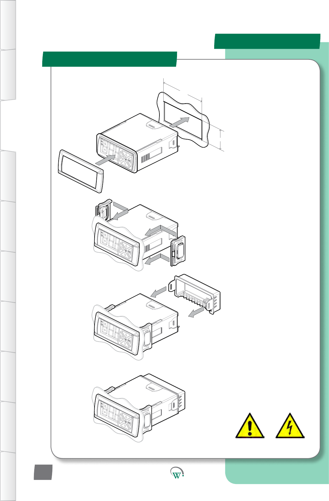
Installaon
Installaon Diagrams
INSTALLATION PROCEDURE
STEP 1
Clip on the Front Fascia Panel.
Cutarectangularapertureinthe
MounngPanelwhichmeasures
71mmwideby29mmhigh.Insert
the SCS™ Connect into the hole.
IMPORTANT: The maximum
permiedmounngpanel
thickness is 9mm. Ensure there
arenoobstrucons7mmtothe
leandrightofthehole,and
4mm above and below. This will
ensure there is clearance with the
Front Fascia. Ensure the hole is
freeofburrsandsharpedges.
STEP 2
Insert the Side Clips into the slots
on the side of the body, and slide
theseforwardsunltheSCS™
Connectisheldsecurelyagainst
themounngpanel.Todisengage
the Side Clips, press the back half
ofthebuonpadinwards,and
then slide the clips backwards.
STEP 3
Aachallcablesfromsensors
and hardware to the controller
connectors.Pleaserefertopage
11 for a list of the terminals
andportsandpage11for
the Hardware Set Up (HSu)
parameters.
STEP 4
Slide the rear cover forwards and
aachusingthetwooutsideclips.
IMPORTANT:Turnoand
isolate the power supply before
removingthiscover.Danger!Risk
ofelectrocuon!
Toremovethecover,gently
disengagethetwoclipsandslide
the cover backwards.
IMPORTANT: Never use an un-
insulated screwdriver to remove
thiscover.Danger!Riskof
electrocuon!
TABLE OF
CONTENTS
INTRODUCTION
& WARNINGS
DESCRIPTION
& INSTALLATION
FRONT PANEL
USER INTERFACE
GRAPHICAL
USER INTERFACE PARAMETERS UPGRADING
FIRMWARE
FAULTS &
ALARMS
TECHNICAL
SPECIFICATION APPENDICES
PD0006 V2.0 – 08 Jan 2016
10
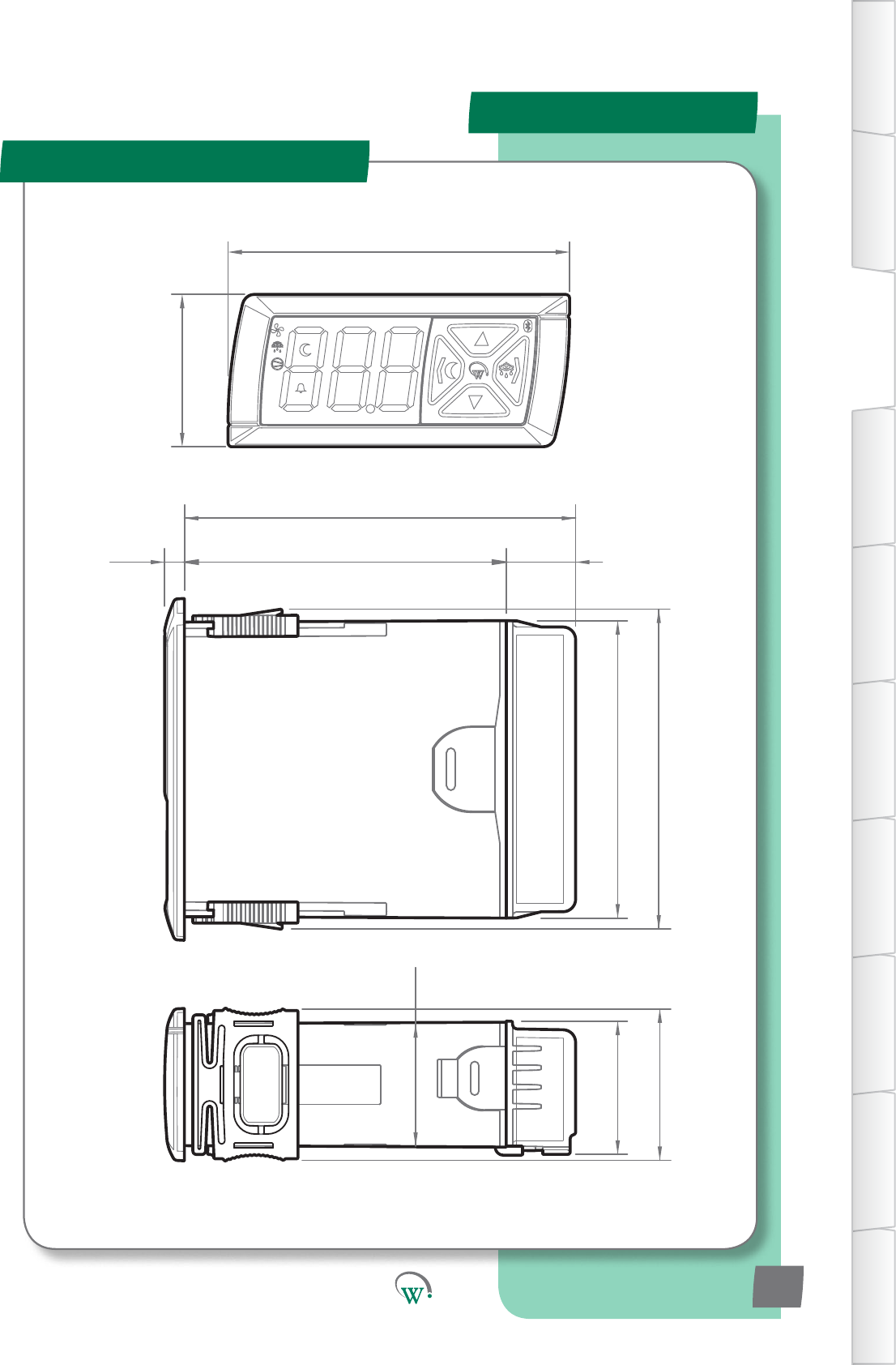
36.2
31.6
35.9
4.7 76.5 16.5
93
70.7
76
81.2
29.0
Installaon
Overall Dimensions
TABLE OF
CONTENTS
INTRODUCTION
& WARNINGS
DESCRIPTION
& INSTALLATION
FRONT PANEL
USER INTERFACE
GRAPHICAL
USER INTERFACE
PARAMETERS
UPGRADING
FIRMWARE
FAULTS &
ALARMS
TECHNICAL
SPECIFICATION
APPENDICES
PD0006 V2.0 – 08 Jan 2016 11
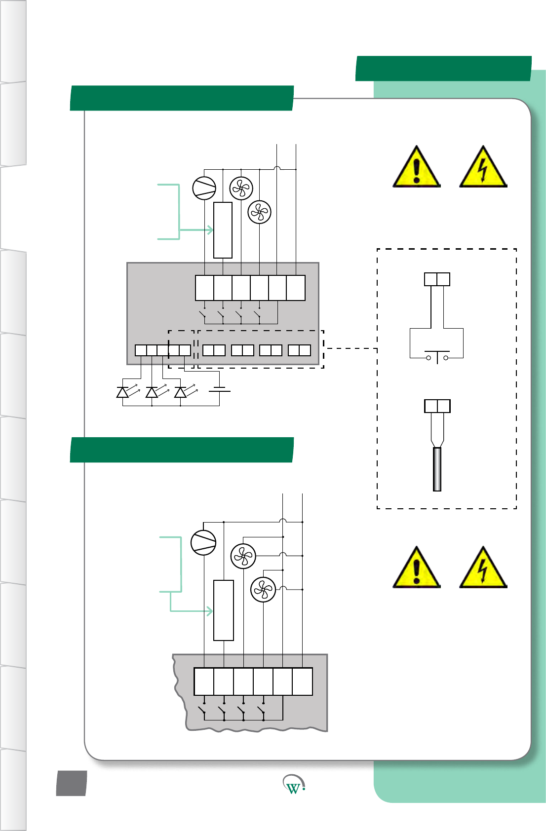
Wiring Diagrams
Standard Installaon
*Variable Speed Motors
Push Button
Door Switch
(Digital)
Temperature
Probe
(Analog)
MAINS CONNECTIONS
Warning!
Risk of Electrocution
Optional customer
dened item;
AC Lights, Defrost
Heater, etc.
Max Load 5A
90 - 240 V AC
N
5A Load Max
(P) L
NPC R S1S2
+++++ ----
12 0V
0V0V0V0V
0 - 24V DC
LED Lighting Modules
PWM
SELV CONNECTIONS
General Digital/
Analog Inputs
90 - 240 V AC
5A Load Max
Optional customer
dened item;
AC Lights, Defrost
Heater, etc.
Max Load 5A
NPC R S1S2
N
(P) L
Black
Black
Brown P
Brown
P
Blue N
Blue N
+-
0V
+-
0V
MAINS CONNECTIONS
Warning!
Risk of Electrocution
*Alternative connection
method for Wellington
Variable Speed Motors.
3
TABLE OF
CONTENTS
INTRODUCTION
& WARNINGS
DESCRIPTION
& INSTALLATION
FRONT PANEL
USER INTERFACE
GRAPHICAL
USER INTERFACE PARAMETERS UPGRADING
FIRMWARE
FAULTS &
ALARMS
TECHNICAL
SPECIFICATION APPENDICES
PD0006 V2.0 – 08 Jan 2016
12
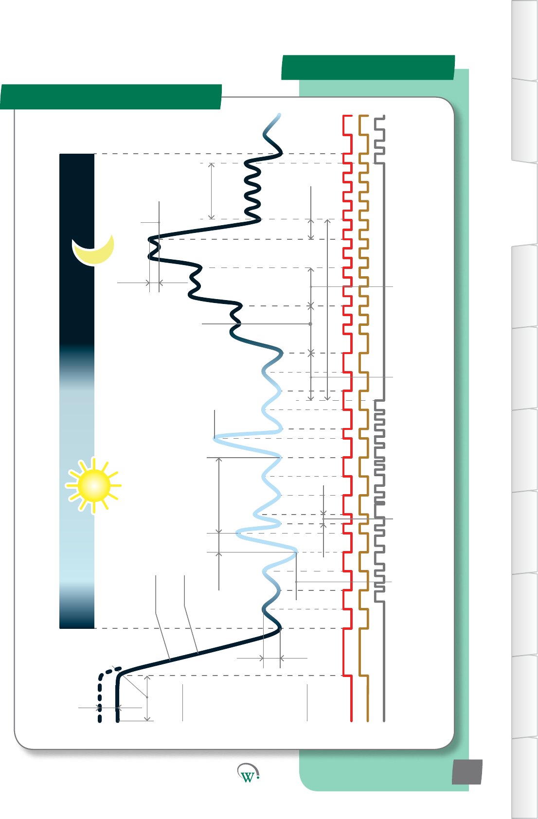
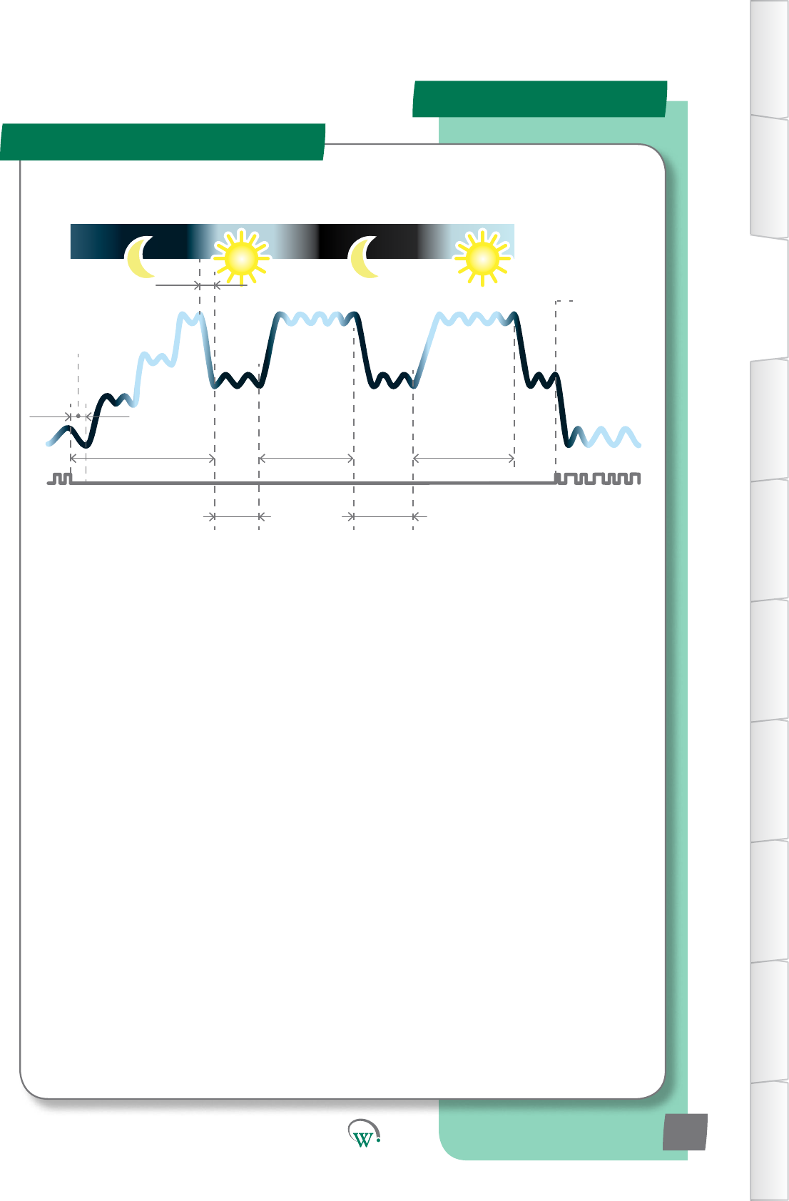
Product Operaon
Operang Cycle
Control Probe
Calibration Offset
(CAL, page 68)
Typical 24 hour cycle
Power
On Delay
(Cot),
page
54) Uninterrupted Pulldown
Temperature (Pdn, page 48)
Evaporator Fan Continuous Run (FCr, page 51)
Maximum
Displayable
Temperature (dSt,
page 58)
Operational
Differential (dIF,
page 29)
Minimum Displayable
Temperature (dP-,
page 58)
Defrost Initiation
Temperature (dIt,
page 48)
Max Defrost
Cycle Time (dCt,
page 48)
Minimum
Compressor
Off Time (Cot,
page 54)
Maximum
Defrost Interval
(dEI, page 49)
Defrost Termination
Temperature (dtt,
page 48)
Inactivity Wait Time
- Normal Mode (ytn,
page 30)
Last Activity
Inactivity Wait Time -
Transition 1
(yt1, page 34)
Inactivity Wait Time -
Transition 2 (yt2, page 37)
Standby Differential
(Sd, page 40)
Standby Set Point
(SSP, page 40)
Maximum Standby Time (Sbt, 41)
Pulldown
Time
(Pdt,
page 41)
Evaporator Fan
Compressor
Detected Activity
Inactivity Wait
Time
- Transition 3
(yt3, page 45)
First Activity
TABLE OF
CONTENTS
INTRODUCTION
& WARNINGS
DESCRIPTION
& INSTALLATION
FRONT PANEL
USER INTERFACE
GRAPHICAL
USER INTERFACE
PARAMETERS
UPGRADING
FIRMWARE
FAULTS &
ALARMS
TECHNICAL
SPECIFICATION
APPENDICES
PD0006 V2.0 – 08 Jan 2016 13
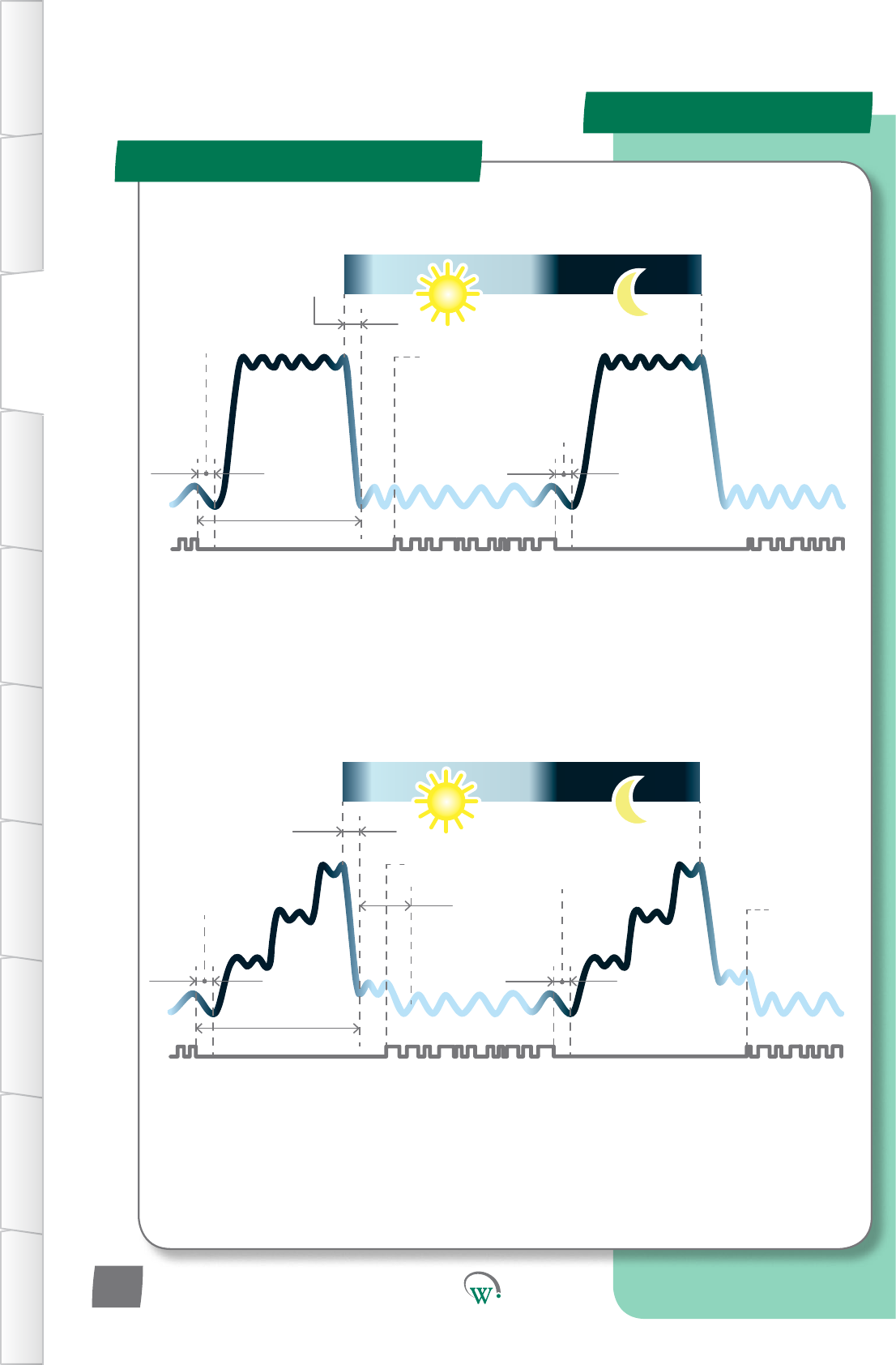
Product Operaon
Standby Refrigeraon Cycles
InacvityWait
Time - Normal
Mode (Ytn)
SP
SSP
Pulldown Time
(Pdt)
Inacvity
Wait Time -
Transion3
(yt3)
Acvity
detected
InacvityWait
Time - Normal
Mode (Ytn)
Maximum
Standby Time
(Sbt)
24 hours
tS1
tS2
Acvitydetected
ADVANCED
DAILY CYCLE
WhenusingtheAdvancedDailyCycle,theSCS™ConnectentersandleavesStandbyModes
inprogressivestagestosaveenergy.Atthestartofeachday,itleavesStandbyModeand
commencesaPulldown.ThisconnuesunlTransion3SetPoint(tS3)isreachedand
theInacvityWaitTime–Transion3(yt3)commences.Duringthismeifanyacvityis
detected,thePulldownconnuesunltheOperaonalSetPoint(SP)isreached.Whenthisis
reached the SCS™ Connect enters the Normal Mode.
WheninNon-PerishableMode,theSCS™ConnectentersStandbyModeatnighttosave
energy.Atthestartofeachday,itleavesStandbyModeandcommencesaPulldown.The
startofthePulldownismedtoensurethattheOperaonalSetPoint(SP)isreachedbefore
therstcustomerAcvityisexpected.WhentheOperaonalSetPoint(SP)isreachedthe
SCS™ Connect enters Normal Mode.
InacvityWait
Time - Normal
Mode (Ytn)
SP
Pulldown Time
(Pdt)
InacvityWait
Time - Normal
Mode (Ytn)
Maximum
Standby Time
(Sbt)
24 hours
Acvitydetected
STANDARD
DAILY CYCLE
Acvity
Acvity
TABLE OF
CONTENTS
INTRODUCTION
& WARNINGS
DESCRIPTION
& INSTALLATION
FRONT PANEL
USER INTERFACE
GRAPHICAL
USER INTERFACE PARAMETERS UPGRADING
FIRMWARE
FAULTS &
ALARMS
TECHNICAL
SPECIFICATION APPENDICES
PD0006 V2.0 – 08 Jan 2016
14
Product Operaon
Refrigeraon Cycle
Acvity
Product Operaon
Standby Refrigeraon Cycles
Maximum
Standby Time
(Sbt)
24 hours
Pulldown Time
(Pdt)
InacvityWait
Time - Normal
Mode (Ytn)
InacvityWaitTime-
Transion3(yt3)
SP
SSP
tS1
tS2
tS3
SSP
tS3
Acvity
detected
CYCLE WHEN
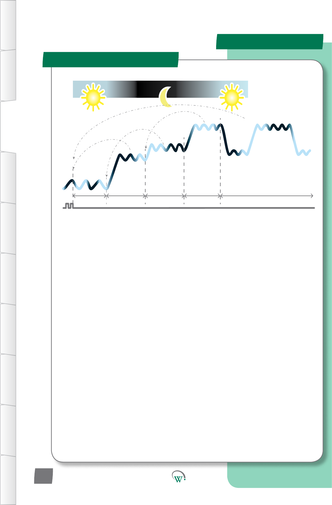
OUTLET CLOSED
Noacvity,outletclosed
Outlet re-opens
IfaRetailOutletdoesnotopenonaparcularday,tosaveenergythesystemreturnstofull
Standby.Thiscanoccurinseveralstages.IfnoacvityisdetectedduringtheInacvityWait
Time–Transion3,theSCS™ConnectreturnstoFullStandbyMode,andisthenreadytostart
thePulldownagainatthestartofthenextdayaspernormal.Shouldanyacvitybedetected
while in Full Standby mode, the SCS™ Connect will immediately commence a Pulldown.
Inacvity
Wait Time
- Standby
Hold (yth)
Inacvity
Wait Time
- Standby
Hold (yth)
InacvityWaitTime-
Transion3(yt3)
TABLE OF
CONTENTS
INTRODUCTION
& WARNINGS
DESCRIPTION
& INSTALLATION
FRONT PANEL
USER INTERFACE
GRAPHICAL
USER INTERFACE
PARAMETERS
UPGRADING
FIRMWARE
FAULTS &
ALARMS
TECHNICAL
SPECIFICATION
APPENDICES
PD0006 V2.0 – 08 Jan 2016 15
IfthecoolerisinNormalmodeandanacvityisseen,the“InacvityWaitTimer-Normal
Mode”willbereset.
IfthecoolerisinTransion1Modeandanacvityisseen,thecoolerwillmovebacktoNormal
Mode,andthe“InacvityWaitTimer-NormalMode”willbereset.
IfthecoolerisinTransion2Modeandanacvityisseen,thecoolerwillmovebackto
Transion1Mode,andthe“InacvityWaitTimer-Transion1”willbereset.
IfthecoolerisinStandbyModeandanacvityisseen,thecoolerwillmovebacktoTransion
2Mode,andthe“InacvityWaitTimer-Transion2”willbereset.
IfthecoolerisinTransion3ModeorStandbyHoldModeandanacvityisseen,thecooler
willmovebacktoNormalMode,andthe“InacvityWaitTimer-NormalMode”willbereset.
Acvity
Product Operaon
Standby Refrigeraon Cycles
DOOR OPEN
STATE CHANGES
Normal Transion1 Transion2 Standby Transion3andStandbyHold
TABLE OF
CONTENTS
INTRODUCTION
& WARNINGS
DESCRIPTION
& INSTALLATION
FRONT PANEL
USER INTERFACE
GRAPHICAL
USER INTERFACE PARAMETERS UPGRADING
FIRMWARE
FAULTS &
ALARMS
TECHNICAL
SPECIFICATION APPENDICES
PD0006 V2.0 – 08 Jan 2016
16

Quick Read
START UP SEQUENCE
Start-Up Sequence
TABLE OF
CONTENTS
INTRODUCTION
& WARNINGS
DESCRIPTION
& INSTALLATION
FRONT PANEL
USER INTERFACE
GRAPHICAL
USER INTERFACE
PARAMETERS
UPGRADING
FIRMWARE
FAULTS &
ALARMS
TECHNICAL
SPECIFICATION
APPENDICES
Step 1: Displays “SCS”.
Step 2: Displays the
Firmware Version.
Step 3: Displays the
Parameter Set Name.
(not yet implemented).
Step 4: Cycles through a
self-test routine.
Step 5: Displays the current
temperature (running in
Normal Mode).
PD0006 V2.0 – 08 Jan 2016 17
PowercyclingtheSCS™Connectiniatesthestartup
sequence,whichgoesthroughthefollowingsteps:
Step 1.
Displays“SCS”.
Step2.
ThecurrentFirmwareVersionisbrieydisplayed.Thisisa6
digitnumber.Therst3digitsaredisplayedfor2seconds,
thentheremaining3digitsfor2seconds.
Step 3. (not yet implemented)
TheloadedParameterSetNameisbrieydisplayed.Thisis
a 6 character alpha-numeric name created by the customer.
Therst3charactersaredisplayedfor2seconds,thenthe
remaining3charactersfor2seconds.
Step 4.
TheSCS™Connectcyclesthroughtheoutputsdisplaying“CoP”,
“FAn”,“LIt”asitself-teststheoutputs.
Step 5.
The SCS™ Connect displays the current temperature and enters
Normal Mode.
Parameter Set Name
The Parameter Set Name is a 6 character alpha-numeric
codecreatedbythecustomertouniquelyidenfythetype
ofrefrigeraonsysteminuseandtheassociatedparameter
conguraonloadedintotheSCS™Connect.Forclarityonthe
displaywerecommendthatthenameshouldbecreatedusing
thefollowingcharacters:
Upper Case Characters:
Lower Case Characters:
Numerals:
Quick Read
FRONT PANEL USER INTERFACE
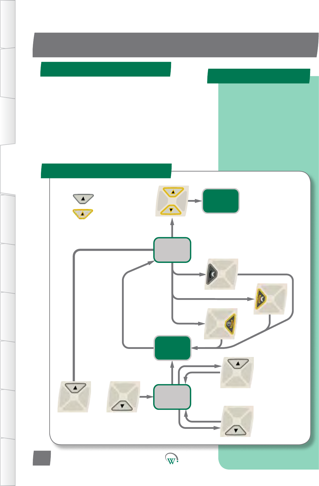
User Mode Flow Chart
User Mode
OR
Display
Temperature
Enter Service
Mode
see 19
Toggle
Lights
Both Together
KEY
=shortbuon
press
=longbuon
press
Display
Setpoint
Value
Increase
Setpoint
Decrease
Setpoint
Ifnobuon
pressedaer
5 seconds
Toggle
Defrost
Toggle
Standby
TABLE OF
CONTENTS
INTRODUCTION
& WARNINGS
DESCRIPTION
& INSTALLATION
FRONT PANEL
USER INTERFACE
GRAPHICAL
USER INTERFACE PARAMETERS UPGRADING
FIRMWARE
FAULTS &
ALARMS
TECHNICAL
SPECIFICATION APPENDICES
Controls the essential
end-user functions; Lights,
Transition Mode, Defrost
Mode, Set Point Temperature.
A PIN code is required to
enter the Service Mode
menus.
PD0006 V2.0 – 08 Jan 2016
18
Thesearetheessenalfunconsthatretailstacancontrol:
ManuallytoggletheLightsonando.
ManuallytoggleStandbyModeonando.
ManuallyiniateaDefrost.
Adjust the Set Point Temperature within a pre-
determinedrange.
* Not yet implemented
Quick Read
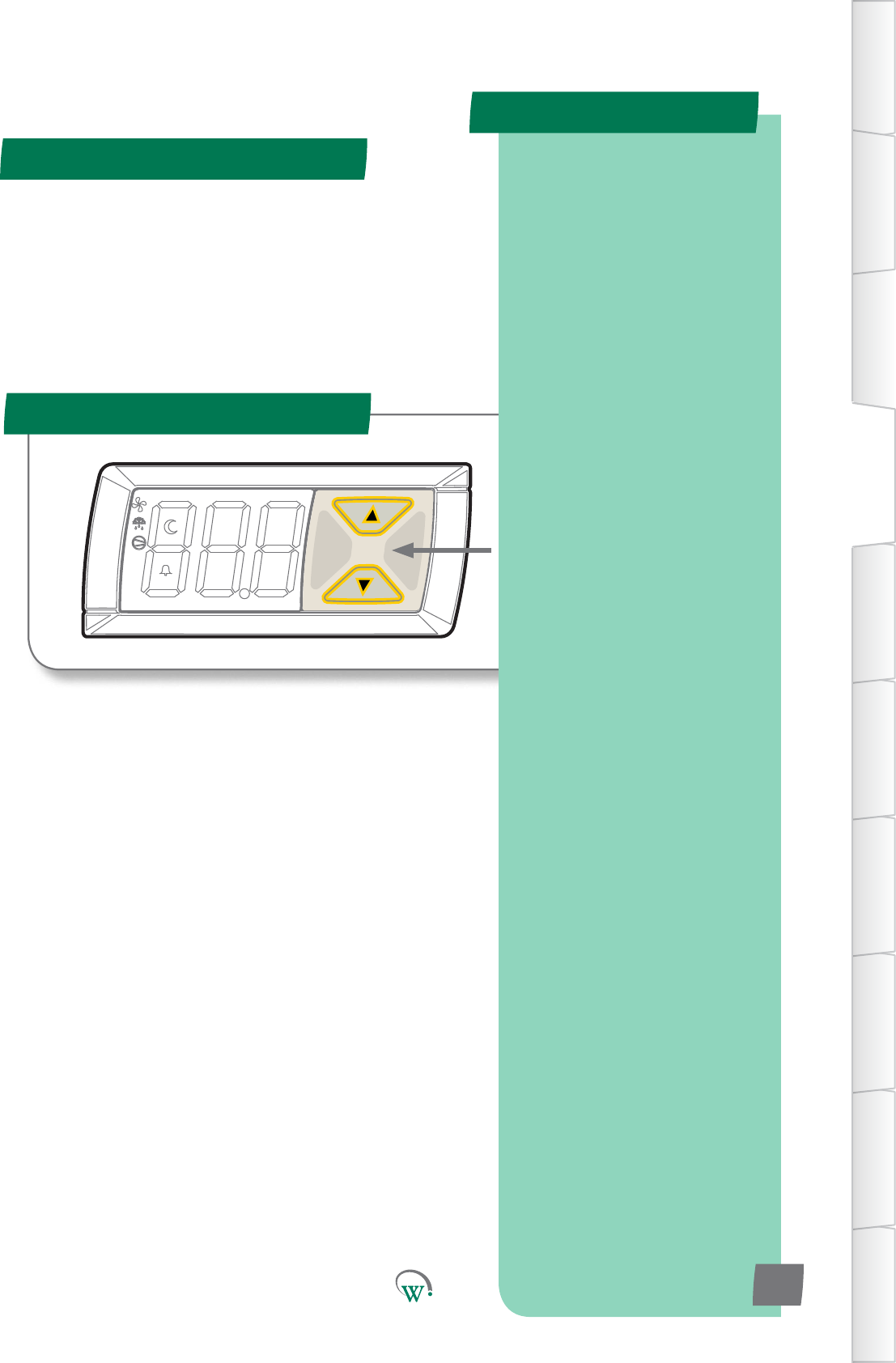
Service Mode
To Enter Service Mode
SERVICE MODE UI
PressUpandDownBuon
togethertoenterServiceMode,
followedbythe9-digitPINcode
TABLE OF
CONTENTS
INTRODUCTION
& WARNINGS
DESCRIPTION
& INSTALLATION
FRONT PANEL
USER INTERFACE
GRAPHICAL
USER INTERFACE
PARAMETERS
UPGRADING
FIRMWARE
FAULTS &
ALARMS
TECHNICAL
SPECIFICATION
APPENDICES
Five main Categories to select
from:
Parameters
Reset
Manual Test
Statistics
About
Two User Interface Flow
Charts:
Parameter, Reset and
Manual Test categories,
page 20.
Statistics and About
categories, page 21.
PD0006 V2.0 – 08 Jan 2016 19
TheServiceModeisenteredfromtheUserModebyholding
downtheUpandDownbuonstogether.
ToaccesstheServiceModeparameters,a9digitPINcode
mustbeentered,consisngofL=le,R=right,U=up,D=down.
Thepincodeisdisplayedinthe“SCSField“appagainstthe
companiesyouareacvatedto.(Seepage23)
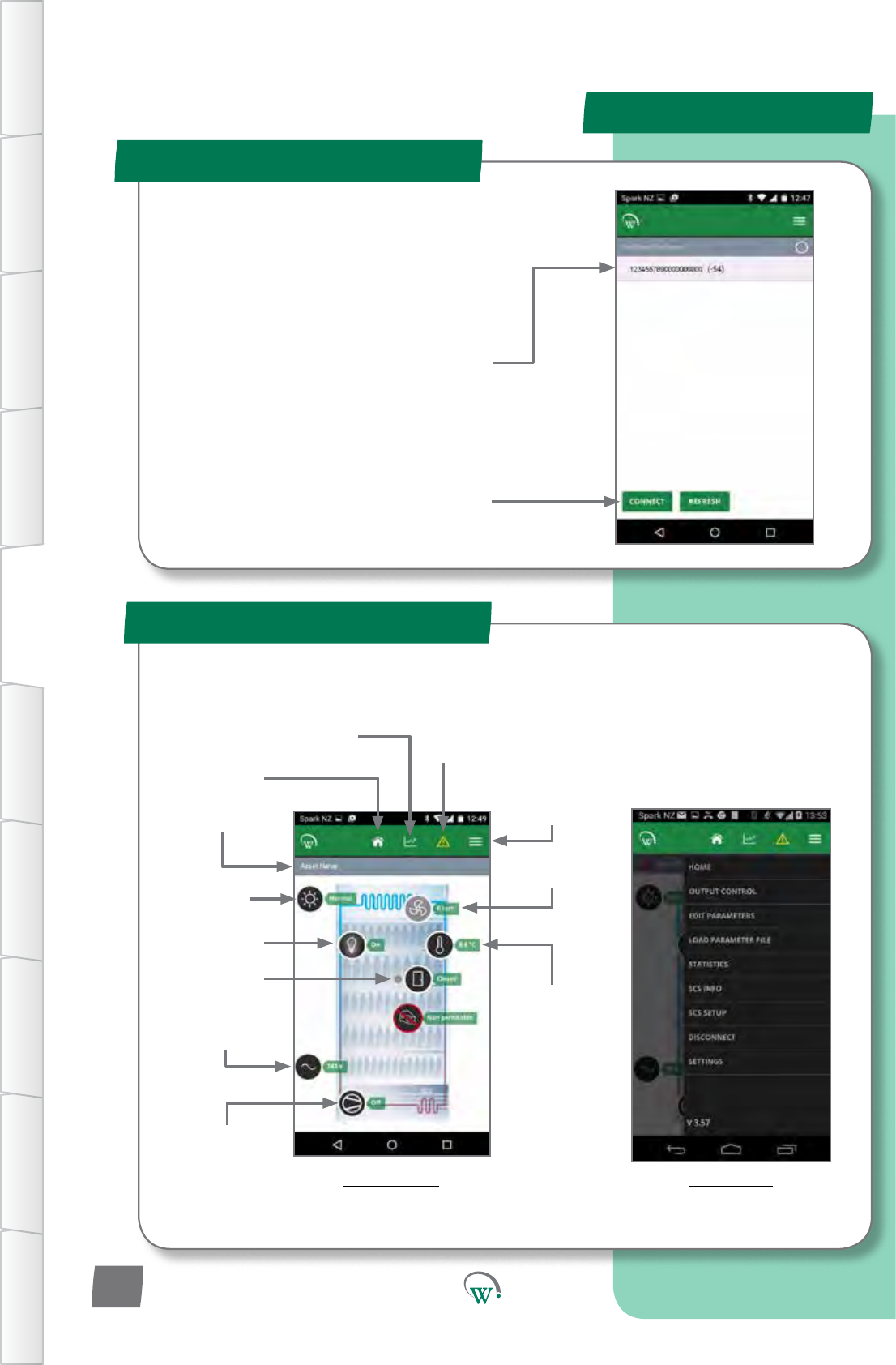
Thereare5categoriesmainServiceModecatagories:
Parameters:Fordetailsonconguringparameters
pleaserefertopage27.
Reset*: Returns the SCS Connect controller back to
FactoryorDefaultSengs.
ManualTest*:AllowsServiceStatoinspectinput
valuesfromsensorsandchecktheeectsofoutput
adjustments to peripherals, and to run preset test
rounes.
Stascs*:Displaysloggedvaluesandeventcountsto
helpServiceStanetuneandtroubleshootthe
system.
About*:Liststheproperesoftherefrigeraon
systemandthecontroller,includingcoolermodel
codes,rmware,hardwareandsowareversions.
TherearetwodierentUserInterfaceFlowChartstofollow
dependingonwhichofthesecategoriesareselected:
FortheParameter,ResetandManualTestcategories,
pleaserefertotheUIFlowChartonpage20.
FortheStascsandAboutcategories,pleasereferto
theUIFlowChartonpage21.
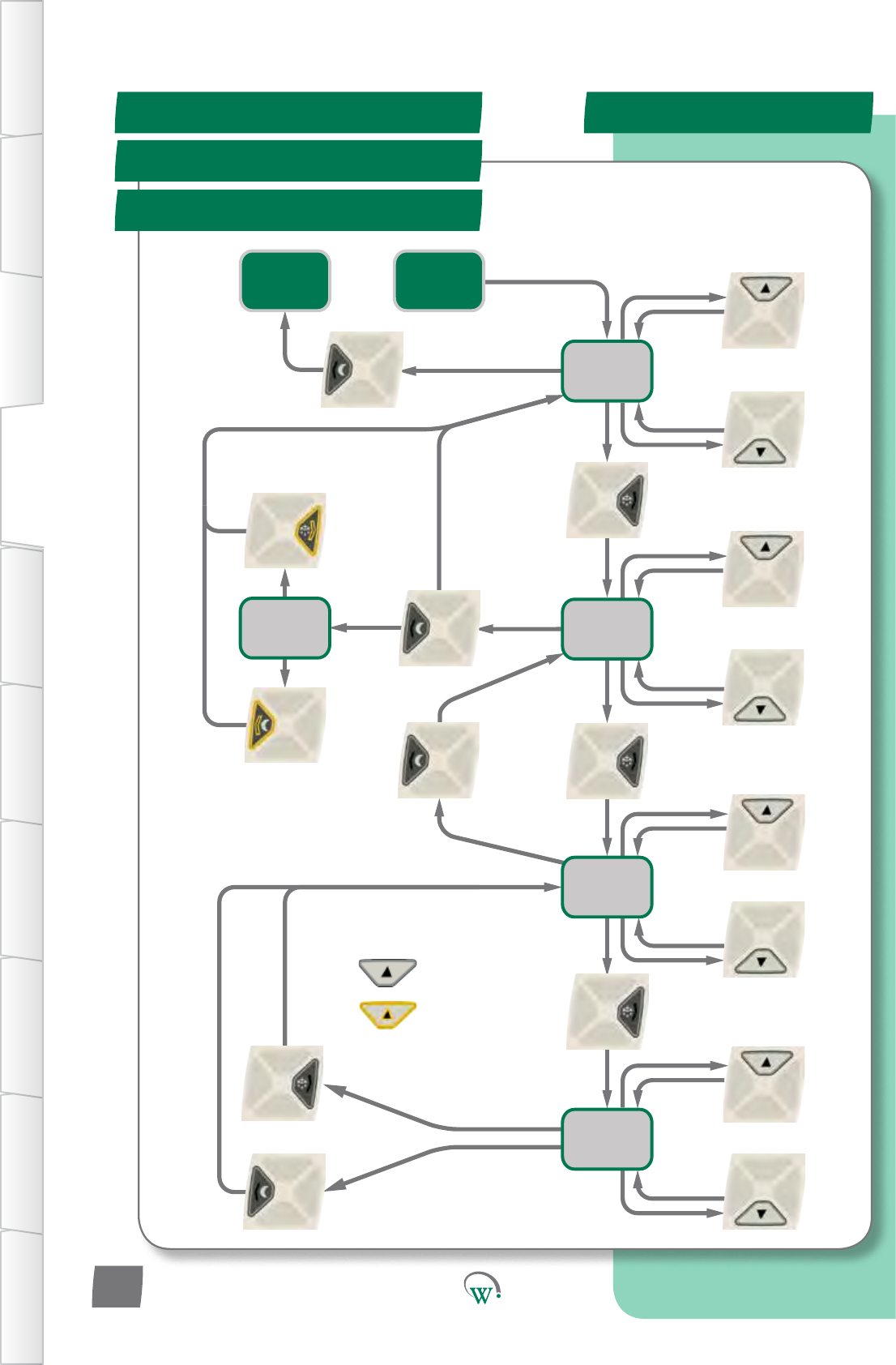
Reset Flow Chart
SERVICE MODE UI - cont
Parameters Flow Chart
Manual Test Flow Chart
Display
Categories
Display
Menu List
Display
Parameter
List
Display
Parameter
Value
Store
Changes
Cancel
Changes
Next
Menu Up
Next Menu
Down
Enter
Selected
Menu
Back To
Menu
List
Next
Parameter
Up
Next
Parameter
Down
Enter
Selecon
Discard
Changes
Save
Changes
To Buer
Increase
Value
Decrease
Value
KEY
=shortbuon
press
=longbuon
press, scroll
Return to
User Mode
page21
Store or
Cancel?
Enter Service
Mode PIN
If Changes = No
Back
Next
Category Up
Next
Category
Down
Exit
Category
List
If Changes
= Yes
Enter
Selected
Category
TABLE OF
CONTENTS
INTRODUCTION
& WARNINGS
DESCRIPTION
& INSTALLATION
FRONT PANEL
USER INTERFACE
GRAPHICAL
USER INTERFACE PARAMETERS UPGRADING
FIRMWARE
FAULTS &
ALARMS
TECHNICAL
SPECIFICATION APPENDICES
PD0006 V2.0 – 08 Jan 2016
20
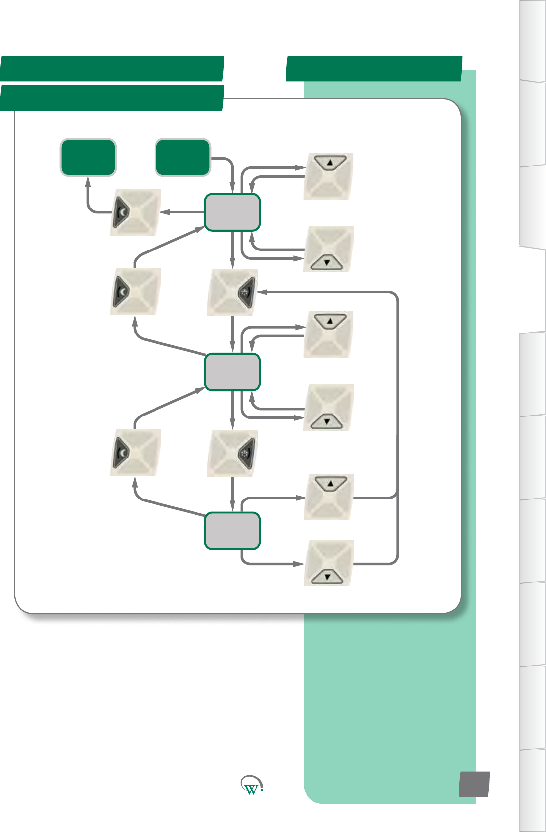
Back To
Category
List
About Flow Chart
SERVICE MODE UI - cont
Stascs Flow Chart
Display
Categories
Display
Menu List
Display
Data Value
Next
Menu Up
Next Menu
Down
Enter
Selected
Menu
Back To
Menu
List
Next Item
Up
Next Item
Down
Return to
User Mode
page22
Enter Service
Mode PIN
Next
Category Up
Next
Category
Down
Exit
Category
List
Enter
Selected
Category
TABLE OF
CONTENTS
INTRODUCTION
& WARNINGS
DESCRIPTION
& INSTALLATION
FRONT PANEL
USER INTERFACE
GRAPHICAL
USER INTERFACE
PARAMETERS
UPGRADING
FIRMWARE
FAULTS &
ALARMS
TECHNICAL
SPECIFICATION
APPENDICES
PD0006 V2.0 – 08 Jan 2016 21
*Customisaonusingcompanycoloursandlogosarealso
available.PleaseseeWellingtonforfurtherdetails.
Quick Read
GRAPHICAL USER INTERFACES
User Interfaces*
TABLE OF
CONTENTS
INTRODUCTION
& WARNINGS
DESCRIPTION
& INSTALLATION
FRONT PANEL
USER INTERFACE
GRAPHICAL
USER INTERFACE PARAMETERS UPGRADING
FIRMWARE
FAULTS &
ALARMS
TECHNICAL
SPECIFICATION APPENDICES
Wellington SCS
Connect controller App:
Bluetooth® LE compliant.
Wireless diagnostics and
control.
Designed for mobile devices
using a touch screen
interface.
Customized app branding
available on special request.
Secure, only authorized
connections permitted.
PD0006 V2.0 – 08 Jan 2016
22
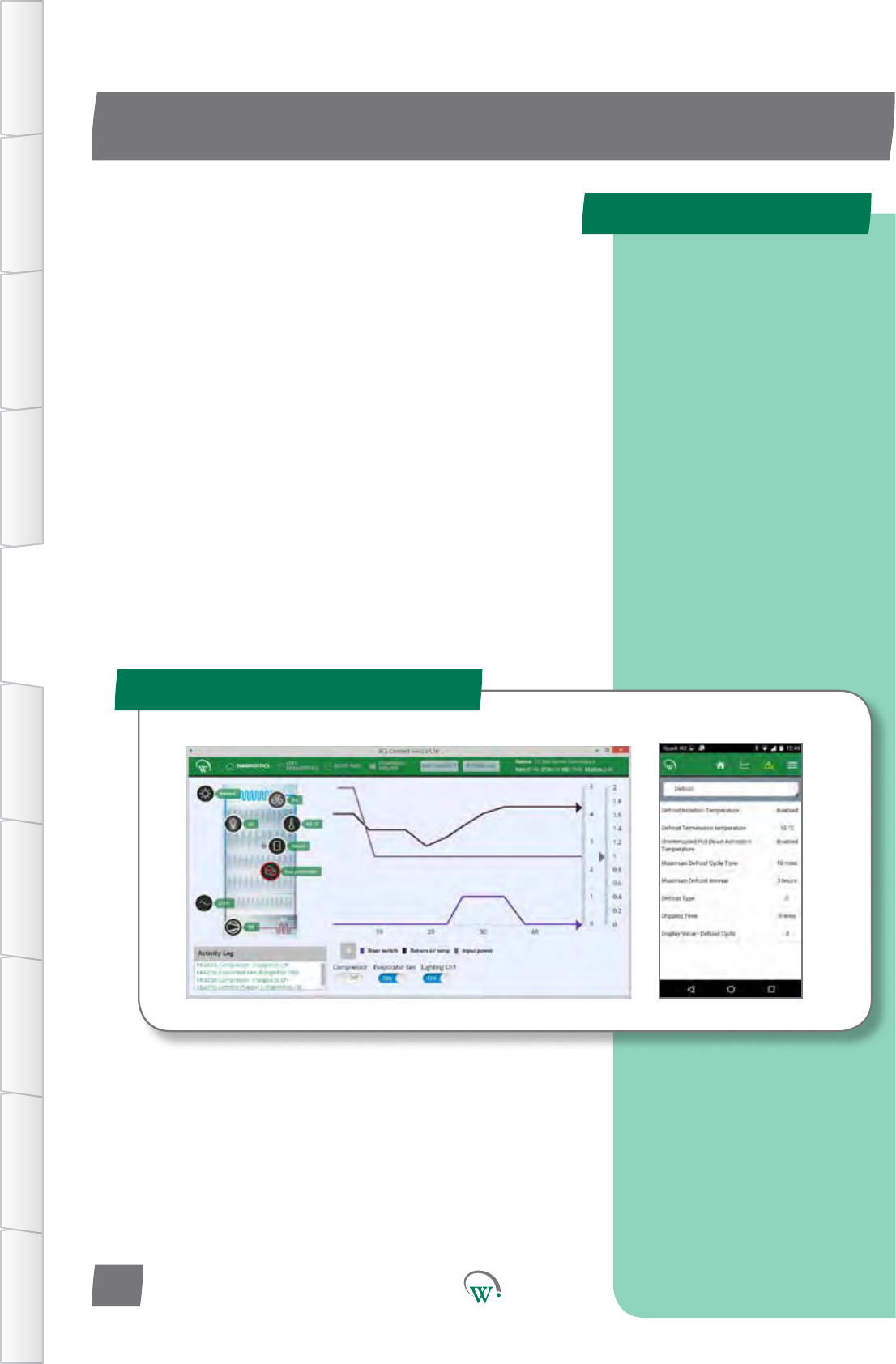
TheWellingtonSCS Connect controller App provides a wireless
connecontotheSCS Connect controller from mobile devices
edwithBluetooth®LE.Thisgivesusersandtechniciansan
unprecedentedlevelofvisibility,controlanddiagnosctools
toopmisethecontroller’sperformanceandtotroubleshoot
anyproblems.Thefollowingguideprovidesanoverviewof
theappanditscapabilies.
Note:Screenshotsshownareindicaveonly.Dierent
deviceshavedierentscreenraos,sizesandresoluons.The
actualimageseenonyourdevicemayvaryfromthescreen
shotsshowninthisguide.Holdingyourdeviceinportraitor
landscapemodemayhaveaneectonappearanceandmay
changehowthevariouswindowsandgraphicsaredisplayed
andarrangedonyourscreen.
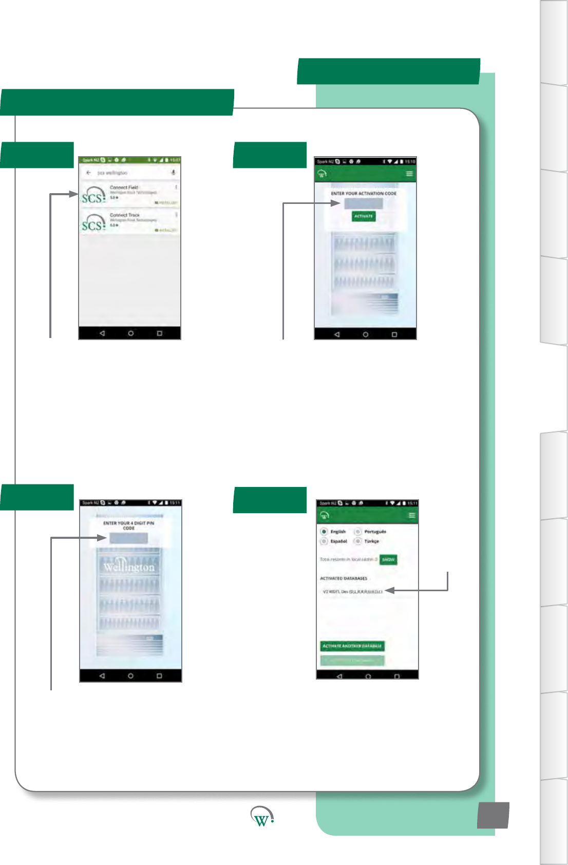
Your9-digit
touch panel
code
Download and install the Connect Field
appfromGooglePlay(Searchfor“scs
wellington”tondit)
Whenyourstrun“ConnectField”,youwill
berequestedtoenteranacvaoncode.
ContactyourUserManagerorWellington
toreceiveyouracvaoncode(Youmust
beconnectedtotheinternetatthemeof
acvaon).
Note:
Youracvaoncodeisuniquetoyou,andshouldNEVERbesharedwithanyoneelse,asit
determinesyourpersonalaccesslevelfortheapp.Thesamecodewillgiveyouaccesstoall
SCS apps you are authorised to use.
Onceacvaoniscomplete,youmust
denea4-digitPINcode.Thiscanbeany
codeuniquetoyou.Eachmeyoustart
the app, you will be required to enter this
same PIN code. This is to prevent other
peopleaccessingtheappfromunlocked
phones.
You can see which databases you are
acvatedagainstfromthe“Sengs”screen.
Youcanbeacvatedtomorethanone
databaseatthesameme.Simplyselect
“ACTIVATEANOTHERDATABASE”,andenter
thenewdatabasesuniqueacvaoncode,
as in Step 2.
Authencaon
Step 1 Step 2
Step 4
Step 3
MOBILE GUI - cont
TABLE OF
CONTENTS
INTRODUCTION
& WARNINGS
DESCRIPTION
& INSTALLATION
FRONT PANEL
USER INTERFACE
GRAPHICAL
USER INTERFACE
PARAMETERS
UPGRADING
FIRMWARE
FAULTS &
ALARMS
TECHNICAL
SPECIFICATION
APPENDICES
PD0006 V2.0 – 08 Jan 2016 23
Compressor
State
Power Supply
Evap Fan
Status
Main Menu
Status Bar
Return-air
Temperature
Mode
Connecng to a Device
Home Screen
MOBILE GUI - cont
TABLE OF
CONTENTS
INTRODUCTION
& WARNINGS
DESCRIPTION
& INSTALLATION
FRONT PANEL
USER INTERFACE
GRAPHICAL
USER INTERFACE PARAMETERS UPGRADING
FIRMWARE
FAULTS &
ALARMS
TECHNICAL
SPECIFICATION APPENDICES
PD0006 V2.0 – 08 Jan 2016
24
Note:IftheBluetooth™logoonthetopright
oftheSCS™Connectbuonpanelislit,then
theBluetooth™signalisbroadcasngandthe
device should be visible.
Thislogowillstartashingwhenconnectedto
a device
Select a device to connect to from the list of
visable devices
Note:Thislistislteredbyyouracvaon
permissions, so devices you are not
authorised to connect to will not be
displayed.
Select“Connect”toconnecttothecooler
MenuBuon
Graph and
Output Control Event History
Home Screen
(FridgeStatus)
Door State
LightState
Home Screen
TheHomeScreenshowsagraphicrepresentaonofthecurrentstate
oftherefrigeraonunitbeingcontrolled.
Step 1 Step 2
Step 4
Step 3
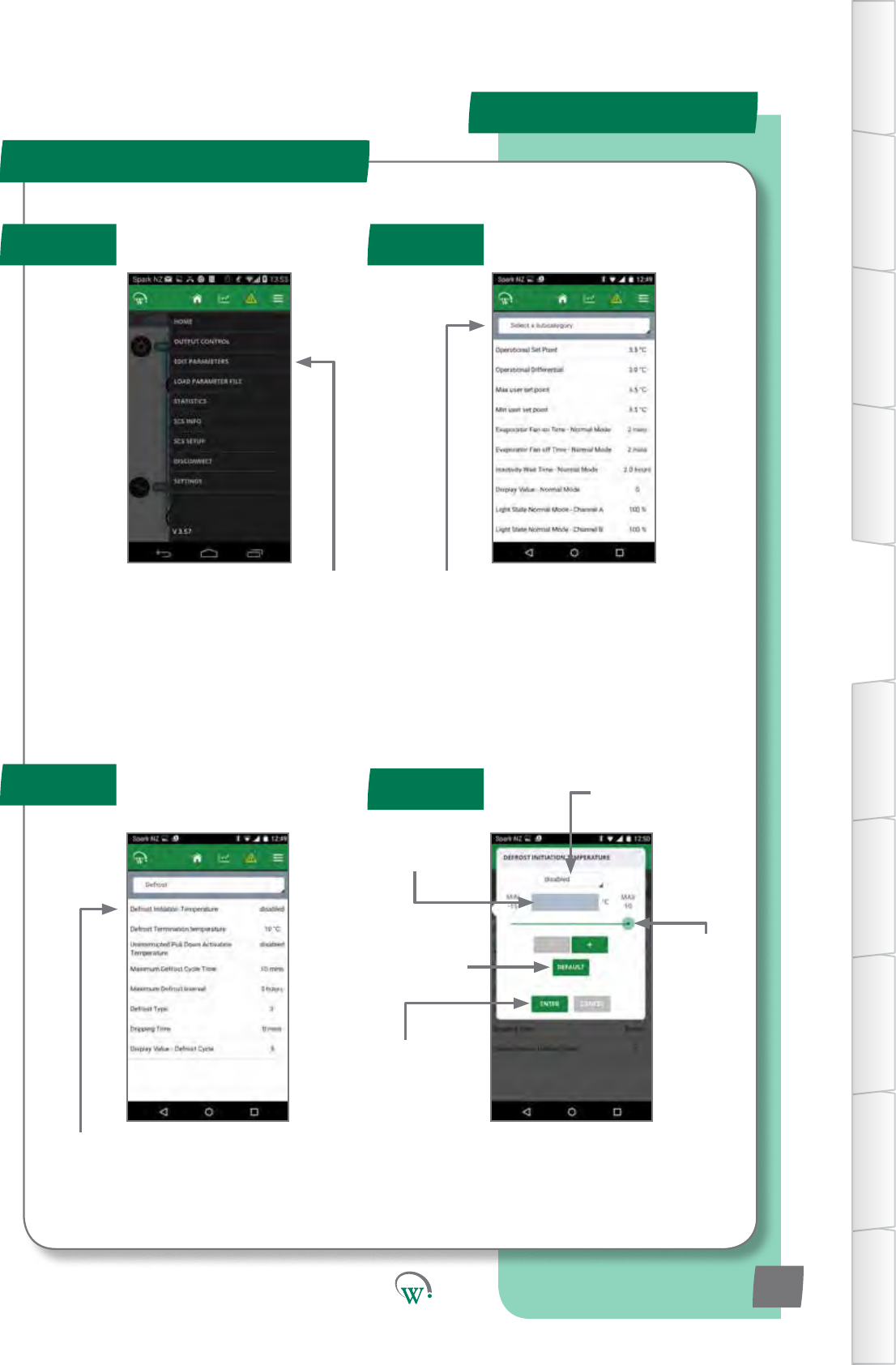
Select“EDITPARAMETERS”fromtheMain
menu
SelecttheparameterCatagoryyouwantto
view
Select the Parameter you want to edit
Pull down box
to select non-
numerical values
Text box to enter
numerical values
directly
Edittheparameter,thenpress“ENTER”to
set it in the controller.
Slider to
select
Numerical
values
Reset to factory
defaultsengs
Applythechangeto
the controller
Parameter Eding
MOBILE GUI - cont
TABLE OF
CONTENTS
INTRODUCTION
& WARNINGS
DESCRIPTION
& INSTALLATION
FRONT PANEL
USER INTERFACE
GRAPHICAL
USER INTERFACE
PARAMETERS
UPGRADING
FIRMWARE
FAULTS &
ALARMS
TECHNICAL
SPECIFICATION
APPENDICES
PD0006 V2.0 – 08 Jan 2016 25
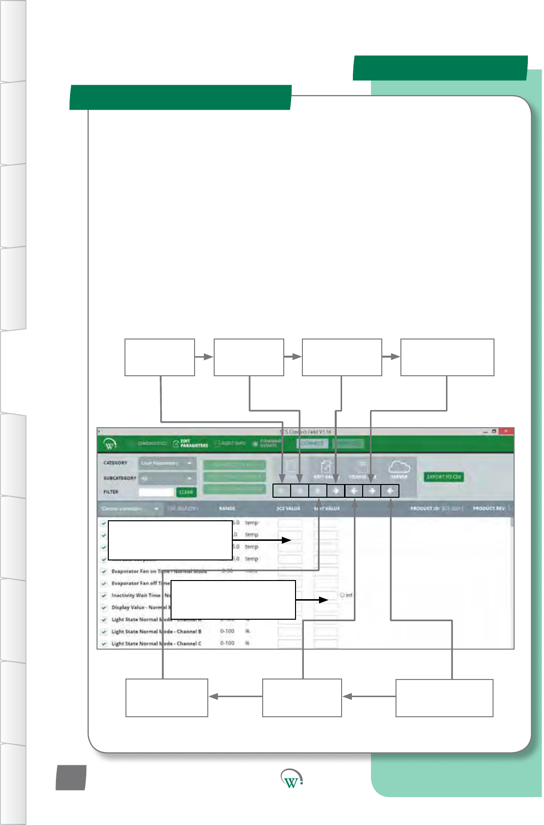
Upload
parameters
from SCS to PC
Copy SCS
parameters to
editable list
Upload parameter
lefromlocal
directory to server
Download
parameters from
Editable list to SCS
Save parameters
from editable list
tole
Load parameters
fromleto
editable list
Download parameter
lefromserverto
local directory
Parameters uploaded from
the SCS are displayed in the
le hand column
Parametersbeingedited
are displayed in the
right hand column
TheDesktopAppisintendedforOEM’sandmanufacturers.Itsupportseasycreaon,checking
andsavingofparameterlesforLabandProduconuse:
•RequiresaBlue-GigaUSBdongletosupportBT-LE
DuetothepoorhandlingofBluetoothLEbyWindows,useofthedesktopappon
WindowscomputersrequiresanexternalBluetoothdevice(“dongle”).Thesupporteddongle
isBlue-GigamodelBLED112,availablefromBlue-GigastockistsorfromWellington.
•Usesthesameacvaoncodeasforallotherapps
• Connects to the controller in the same way as the mobile app
• Basic 4-screen interface (no hidden menus)
-Diagnoscs
- Edit Parameters
- Asset Info
- Firmware Update
Parameter Eding - Desktop
DESKTOP GUI
TABLE OF
CONTENTS
INTRODUCTION
& WARNINGS
DESCRIPTION
& INSTALLATION
FRONT PANEL
USER INTERFACE
GRAPHICAL
USER INTERFACE PARAMETERS UPGRADING
FIRMWARE
FAULTS &
ALARMS
TECHNICAL
SPECIFICATION APPENDICES
PD0006 V2.0 – 08 Jan 2016
26
Quick Read
PARAMETERS
Normal Mode (nrL)
Operaonal
Dierenal(dIF1)
Max User Set
Point (SPt)
Min User Set Point (SP-)
OperaonalSetPoint(SP)
InacvityWait
Time - Normal
Mode (Ytn)
TABLE OF
CONTENTS
INTRODUCTION
& WARNINGS
DESCRIPTION
& INSTALLATION
FRONT PANEL
USER INTERFACE
GRAPHICAL
USER INTERFACE
PARAMETERS
UPGRADING
FIRMWARE
FAULTS &
ALARMS
TECHNICAL
SPECIFICATION
APPENDICES
A full alphabetical
summary list of all
available parameters can
be found on Pg 96.
Parameters shown here
are correct for rmware
versions 1557 to 1558.
Earlier or later rmare
versions may vary.
PD0006 V2.0 – 08 Jan 2016 27
The SCS Connectparametershavebeengroupedtogetheras
follows:
NormalMode(nrL)page27.
Transion1Mode(tn1)page33.
Transion2Mode(tn2)page36.
StandbyMode(SdY)page39
Transion3Mode(tn3)page44.
DefrostMode(dEF)page68.
DoorMenu(dor)page51.
CompressorMenu(CoP)page54.
SupplyMenu(nrG)page56.
DisplayMenu(dSP)page57.
HardwareSetUpMenu(HSu)page59.
GeneralAlarmsMenu(GAL)page72.
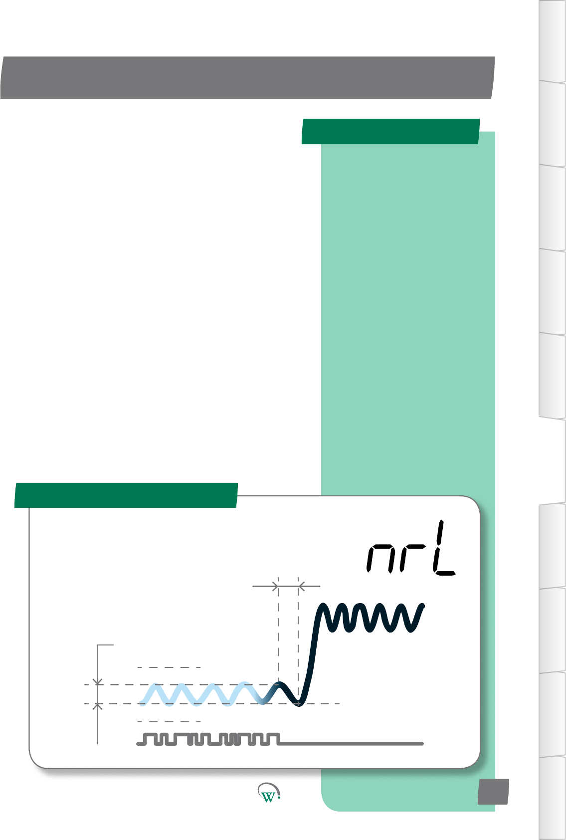
WhenrunninginNormalMode,theSCS Connect controller
primarily operates to maintain the Set Point Temperature.
PARAMETERS
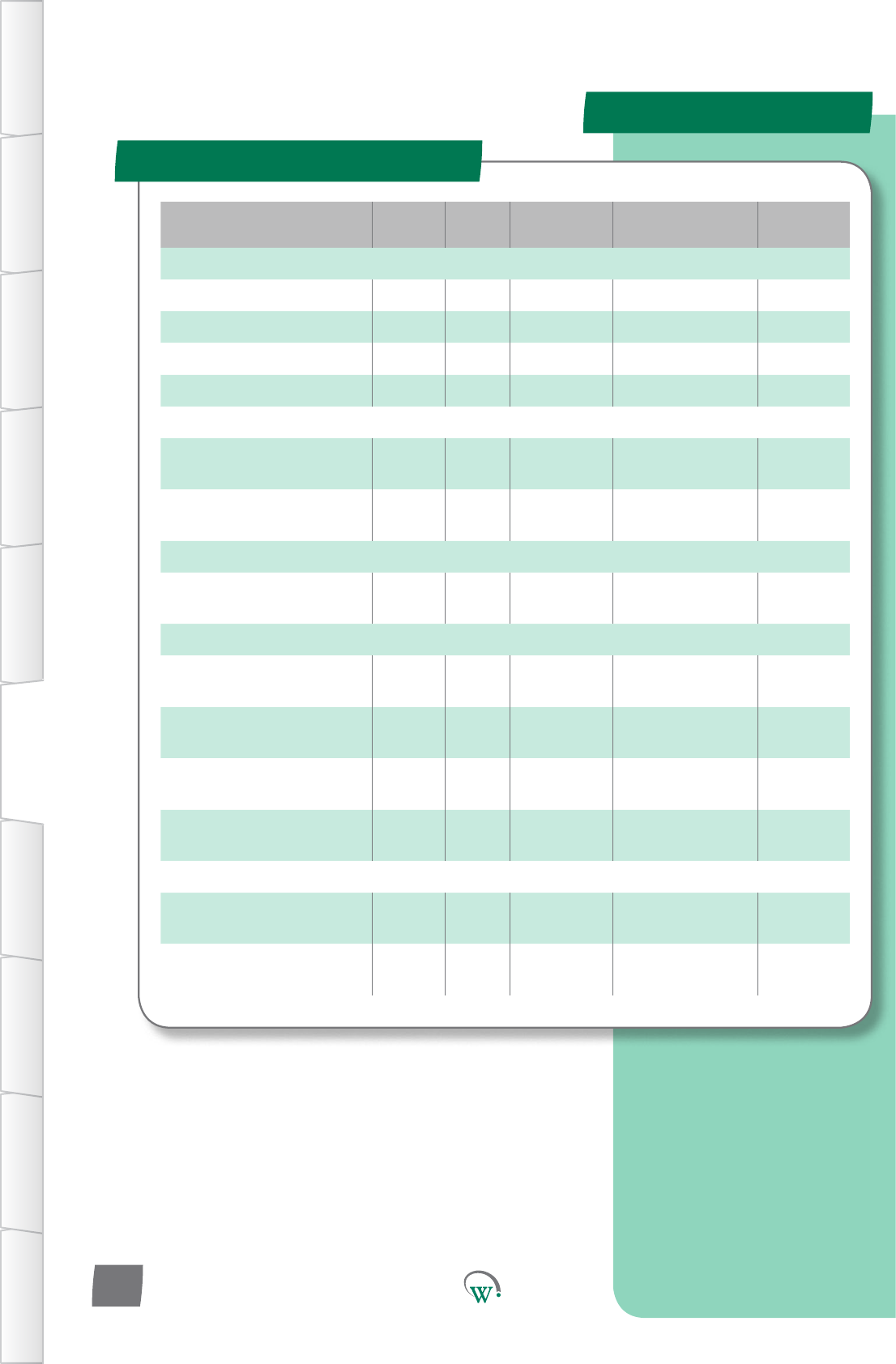
Parameter Name Digital
Display Pages Increments&
Units Range Default
TEMPERATURE
OperaonalSetPoint SP 29 0.1 °C -10.0 to 15.0 °C 3.5 °C
OperaonalDierenal dIF 29 0.1 °C 0.1 to 10.0 °C 3.0 °C
Maximum User Set Point SPt 29 0.1 °C -10.0 to 15.0 °C 3.5 °C
Minimum User Set Point SP- 29 0.1 °C -10.0 to 15.0 °C 3.5 °C
EVAPORATOR
Evaporator Fan On Time -
Normal Mode Fot 30 1 min 0 to 30 mins 2 mins
EvaporatorFanOTime-
Normal Mode FoF 51 1 min 0 to 30 mins 2 mins
TIME
InacvityWaitTime
- Normal Mode Ytn 30 0.5 hours 0.5 to 24 hours
or InFinite 2 hours
LIGHTING & DISPLAY
DisplayValueDuring
Normal Mode dIS 30 integers 0 0
LightStateNormalMode
- Channel A LnA 31 1% 0% to 100% 100%
LightStateNormalMode
- Channel B Lnb 31 1% 0% to 100% 100%
LightStateNormalMode
- Channel C LnC 31 1% 0% to 100% 100%
ALARMS
HighTemperature
Alarm Set Point htA 32 0.1 °C dISabled dISabled
Low Temperature Alarm Set
Point LtA 32 0.1 °C dISabled dISabled
Normal Mode (nrL) - cont
TABLE OF
CONTENTS
INTRODUCTION
& WARNINGS
DESCRIPTION
& INSTALLATION
FRONT PANEL
USER INTERFACE
GRAPHICAL
USER INTERFACE PARAMETERS UPGRADING
FIRMWARE
FAULTS &
ALARMS
TECHNICAL
SPECIFICATION APPENDICES
PD0006 V2.0 – 08 Jan 2016
28
PARAMETERS
Normal Mode (nrL) - cont
TABLE OF
CONTENTS
INTRODUCTION
& WARNINGS
DESCRIPTION
& INSTALLATION
FRONT PANEL
USER INTERFACE
GRAPHICAL
USER INTERFACE
PARAMETERS
UPGRADING
FIRMWARE
FAULTS &
ALARMS
TECHNICAL
SPECIFICATION
APPENDICES
PD0006 V2.0 – 08 Jan 2016 29
Digital
Display
Funconal
Category ParameterRange Increments
&Units Default Related Menus
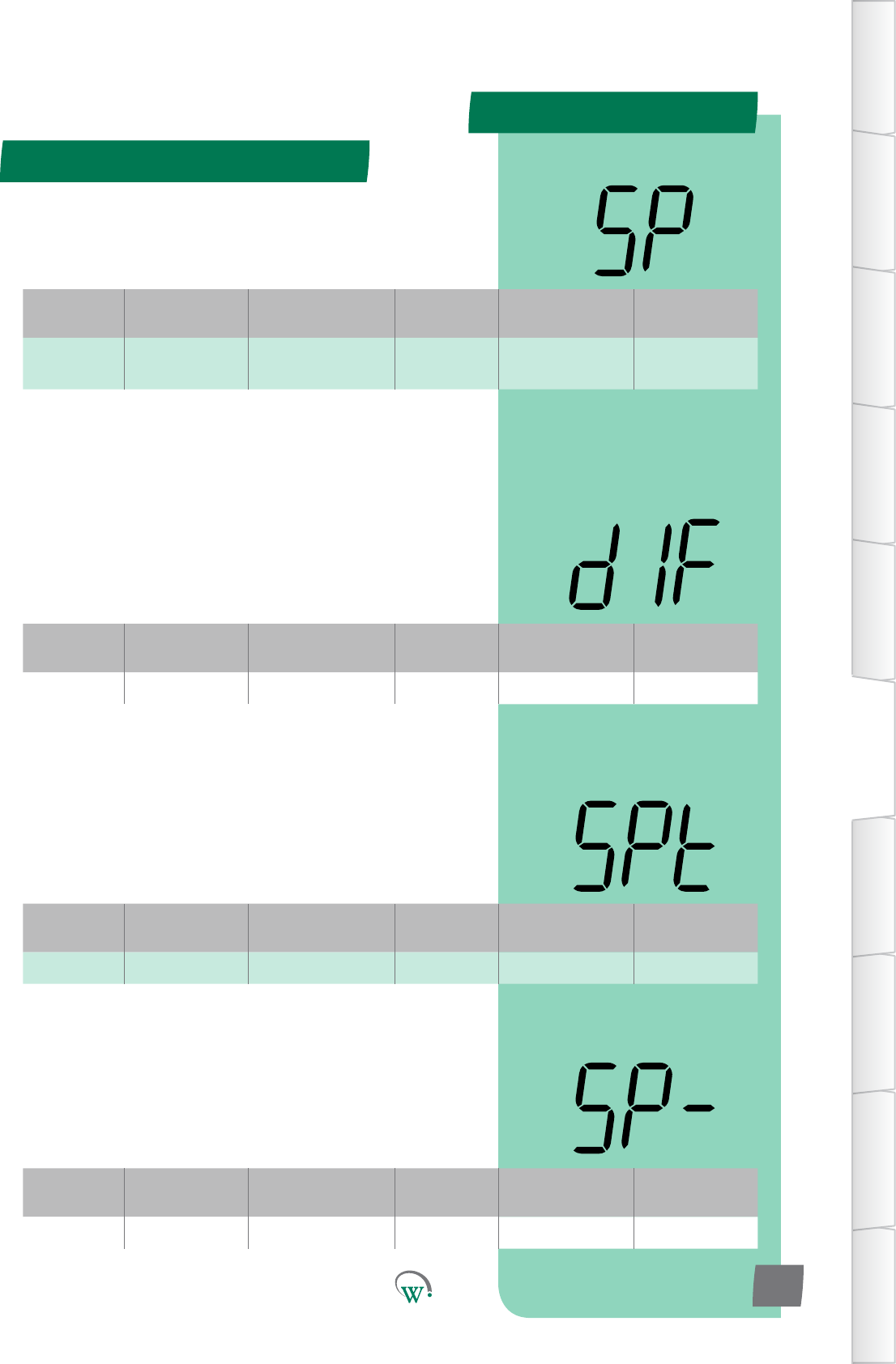
dIF Temperature 0.1 to 10.0 °C 0.1 °C 3.0 °C SP
OPERATIONAL DIFFERENTIAL (dIF)
Thetemperaturedierenal(ΔT)abovetheOperaonalSet
Point (SP) temperature, which will cause the Compressor to
turn on when in Normal Mode. The Compressor will remain on
unlthetemperaturereachestheOperaonalSetPoint(SP)
temperature.
Turn On Temperature = SP + dIF
Digital
Display
Funconal
Category ParameterRange Increments
&Units Default Related Menus
SPt Temperature -10.0 to 15.0 °C 0.1 °C 3.5 °C SP, SP-
MAXIMUM USER SET POINT (SPt)
ThehighesttemperaturethattheRetailStacanadjustthe
cabinet to run at.
Digital
Display
Funconal
Category ParameterRange Increments
&Units Default Related Menus
SP- Temperature -10.0 to 15.0 °C 0.1 °C 3.5 °C SP, SPt
MINIMUM USER SET POINT (SP-)
ThelowesttemperaturethattheRetailStacanadjustthe
cabinet to run at.
Digital
Display
Funconal
Category ParameterRange Increments
&Units Default Related Menus
SP Temperature -10.0 to 15.0 °C 0.1 °C 3.5 °C dIF 1, SP-, SPt,
dIt
OPERATIONAL SET POINT (SP)
ThetemperatureatwhichtheCompressorwillturno,when
thesystemisrunninginNormalMode.Ifthetemperatureis
belowthisvalue,theCompressorwillremaino.
PARAMETERS
Normal Mode - cont
TABLE OF
CONTENTS
INTRODUCTION
& WARNINGS
DESCRIPTION
& INSTALLATION
FRONT PANEL
USER INTERFACE
GRAPHICAL
USER INTERFACE PARAMETERS UPGRADING
FIRMWARE
FAULTS &
ALARMS
TECHNICAL
SPECIFICATION APPENDICES
PD0006 V2.0 – 08 Jan 2016
30
Digital
Display
Funconal
Category ParameterRange Increments
&Units Default Related Menus
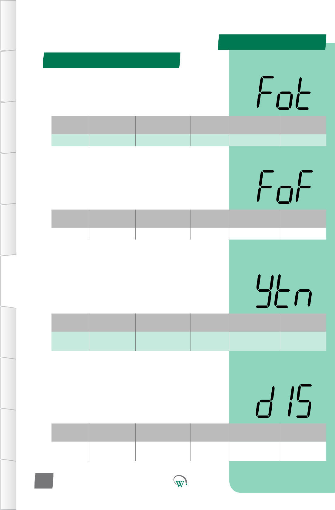
Fot Evaporator 0 to 30 mins 1 min 2 mins FoF, FCr
EVAPORATOR FAN ON TIME–NORMALMODE(Fot)
ThemethefanisoniftheEvaporatorFanissettocyclingin
(FCn)andtheCompressoriso.
Pleasenote:ThetotalEvaporatorFancycle=theonme+the
ome.PleasealsorefertoFoF.
Digital
Display
Funconal
Category ParameterRange Increments
&Units Default Related Menus
FoF Evaporator 0 to 30 mins 1 min 2 mins FCr, Fot
EVAPORATOR FAN OFFTIME–NORMALMODE(FoF)
ThemethefanisoiftheEvaporatorFanissettocyclingin
(FCn)andtheCompressoriso.
Pleasenote:ThetotalEvaporatorFancycle=theonme+the
ome.PleasealsorefertoFCr.
Digital
Display
Funconal
Category ParameterRange Increments
&Units Default Related Menus
ytn Time 0.5 to 24 hours
orinnite 0.5 hours 4 hours tS1, tS2
INACTIVITYWAITTIME–NORMALMODE(ytn)
ThemetheSCS™ConnectwillwaitinNormalModewithout
anyacvitybeingseenbeforeitwillmovetoTransion1Mode.
Anacvityisanyinteraconwiththecabinetwhichisdetected
byasensor,suchastheopeningofthecabinetdoor.
Digital
Display
Funconal
Category ParameterRange Increments
&Units Default Related Menus
dIS Lighng&
Display 0integers 0 SP
DISPLAY VALUE DURING NORMAL MODE (dIS)
SelectswhatisdisplayedduringNormalMode:
0 = Displays the temperature.
1* = Displays the Set Point Temperature.
2*=Displayisleblank.
* not yet enabled
Normal Mode - cont
TABLE OF
CONTENTS
INTRODUCTION
& WARNINGS
DESCRIPTION
& INSTALLATION
FRONT PANEL
USER INTERFACE
GRAPHICAL
USER INTERFACE
PARAMETERS
UPGRADING
FIRMWARE
FAULTS &
ALARMS
TECHNICAL
SPECIFICATION
APPENDICES
PD0006 V2.0 – 08 Jan 2016 31
Digital
Display
Funconal
Category ParameterRange Increments
&Units Default Related Menus
LnA Lighng&
Display 0% to 100% 1% 100% Ldn
LIGHT STATE - NORMAL MODE CHANNEL A (LnA)
TheilluminaonlevelduringNormalModeofChannelAasa
percentageoffullilluminaon.
Note:Lightlevelsofbetween0%and100%areonlyavailable
ifChannelAisassignedtoanLEDoutput.Ifassignedtoa
digitaloutput,thenanylevelotherthan0%willresultin100%
illuminaonlevel.
LIGHT STATE - NORMAL MODE CHANNEL B (Lnb)
TheilluminaonlevelduringNormalModeofChannelBasa
percentageoffullilluminaon.
Note:Lightlevelsofbetween0%and100%areonlyavailable
ifChannelBisassignedtoanLEDoutput.Ifassignedtoa
digitaloutput,thenanylevelotherthan0%willresultin100%
illuminaonlevel.
LIGHT STATE - NORMAL MODE CHANNEL C (LnC)
TheilluminaonlevelduringNormalModeofChannelCasa
percentageoffullilluminaon.
Note:Lightlevelsofbetween0%and100%areonlyavailable
ifChannelCisassignedtoanLEDoutput.Ifassignedtoa
digitaloutput,thenanylevelotherthan0%willresultin100%
illuminaonlevel.
Digital
Display
Funconal
Category ParameterRange Increments
&Units Default Related Menus
Lnb Lighng&
Display 0% to 100% 1% 100% Ldn
Digital
Display
Funconal
Category ParameterRange Increments
&Units Default Related Menus
LnC Lighng&
Display 0% to 100% 1% 100% Ldn
PARAMETERS
Normal Mode - cont
TABLE OF
CONTENTS
INTRODUCTION
& WARNINGS
DESCRIPTION
& INSTALLATION
FRONT PANEL
USER INTERFACE
GRAPHICAL
USER INTERFACE PARAMETERS UPGRADING
FIRMWARE
FAULTS &
ALARMS
TECHNICAL
SPECIFICATION APPENDICES
PD0006 V2.0 – 08 Jan 2016
32
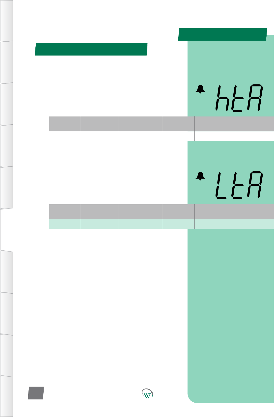
* HIGH TEMPERATURE ALARM SET POINT (htA)
TheSetPointTemperatureabovewhichanalarmistriggered.
ThisfunconislinkedtoHACCPapplicaonswhereitiscrical
thattheproductinsidethecabinetstayswithinaspecic
temperaturerange(eg;vaccines).Pleasealsorefertothe
‘Perishable’funcon(Per).
* Not yet enabled
* LOW TEMPERATURE ALARM SET POINT (LtA)
TheSetPointTemperaturewhichtriggersalowtemperature
alarm.ThisfunconislinkedtoHACCPapplicaonswhere
itiscricalthattheproductinsidethecabinetstayswithina
specictemperaturerange(eg;vaccines).Pleasealsoreferto
the‘Perishable’funcon(Per).
* Not yet enabled
Digital
Display
Funconal
Category ParameterRange Increments
&Units Default Related Menus
htA Alarms dISabled 0.1 °C dISabled PEr
Digital
Display
Funconal
Category ParameterRange Increments
&Units Default Related Menus
LtA Alarms dISabled 0.1 °C dISabled PEr
PARAMETERS
Parameter Name Digital
Display Pages Increments
&Units Range Default
TEMPERATURE
Transion1SetPoint tS1 34 0.1 °C -10.0 to 15.0 °C 5.0 °C
Transion1Dierenal td1 34 0.1 °C 0.1 to 10.0 °C 3.0 °C
TIME
InacvityWaitTime-
Transion1 yt1 34 0.5 hours 0.0 to 24.0 hours 1 hours
LIGHTING & DISPLAY
LightStateTransion1
Mode - Channel A L1A 35 1% 0% to 100% 50%
LightStateTransion1
Mode - Channel B L1b 35 1% 0% to 100% 50%
LightStateTransion1
Mode - Channel C L1C 35 1% 0% to 100% 50%
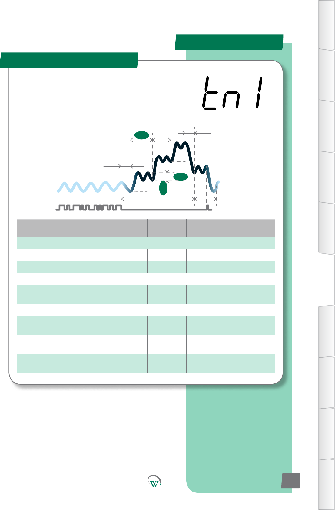
Transion 1 Mode (tn1)
SP
tS1
Sbt
tS2
Ytn
SSP
Pdt
yt3
td1
tS3
yt1 yt2
TABLE OF
CONTENTS
INTRODUCTION
& WARNINGS
DESCRIPTION
& INSTALLATION
FRONT PANEL
USER INTERFACE
GRAPHICAL
USER INTERFACE
PARAMETERS
UPGRADING
FIRMWARE
FAULTS &
ALARMS
TECHNICAL
SPECIFICATION
APPENDICES
PD0006 V2.0 – 08 Jan 2016 33
TheTransionModesareusedtominimizePulldownmes.
Transionalsetpointtemperaturesareusedthatarein
betweentheOperaonalSetPointandfullStandbySetPoint.
TheTransionModesmaybemostusefuliftheretailoutlet
openinghoursvary,orifcustomerdemandvaries,suchthata
regularPulldownmeisuncertain.
PARAMETERS
Digital
Display
Funconal
Category ParameterRange Increments
&Units Default Related Menus
td1 Temperature 0.1 to 10.0 °C 0.1 °C 3.0 °C tS1
Digital
Display
Funconal
Category ParameterRange Increments
&Units Default Related Menus
yt1 Time 0 to 24 hours 0.5 hours 1 hours yt2, Ytn
Digital
Display
Funconal
Category ParameterRange Increments
&Units Default Related Menus
tS1 Temperature -10.0 to 15.0 °C 0.1 °C 5.0 °C td1
Transion 1 Mode (tn1) - cont
TABLE OF
CONTENTS
INTRODUCTION
& WARNINGS
DESCRIPTION
& INSTALLATION
FRONT PANEL
USER INTERFACE
GRAPHICAL
USER INTERFACE PARAMETERS UPGRADING
FIRMWARE
FAULTS &
ALARMS
TECHNICAL
SPECIFICATION APPENDICES
PD0006 V2.0 – 08 Jan 2016
34
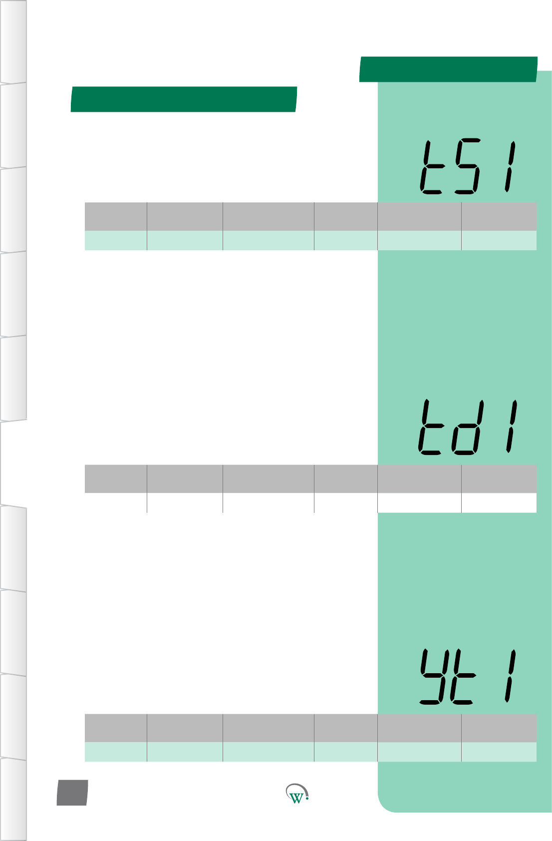
INACTIVITY WAIT TIME - TRANSITION 1 (yt1)
ThemaximummepermiedinTransion1Modewithoutany
detectedacvity,beforeswitchingtoTransion2Mode.
TRANSITION 1 DIFFERENTIAL (td1)
ThetemperatureabovetheTransion1SetPoint(tS1)
temperature, which will cause the Compressor to turn on
wheninTransion1Mode.TheCompressorwillremainon
unlthetemperaturereachestheTransion1SetPoint(tS1)
temperature.
Turn On Temperature = tS1 + td1
TRANSITION 1 SET POINT (tS1)
ThetemperatureatwhichtheCompressorwillturno,when
thesystemisrunninginTransion1Mode.Transion1Mode
istherststepintheStandbyprocesstoconservepower
duringprolongedperiodsofinacvity.
PARAMETERS
Digital
Display
Funconal
Category ParameterRange Increments
&Units Default Related Menus
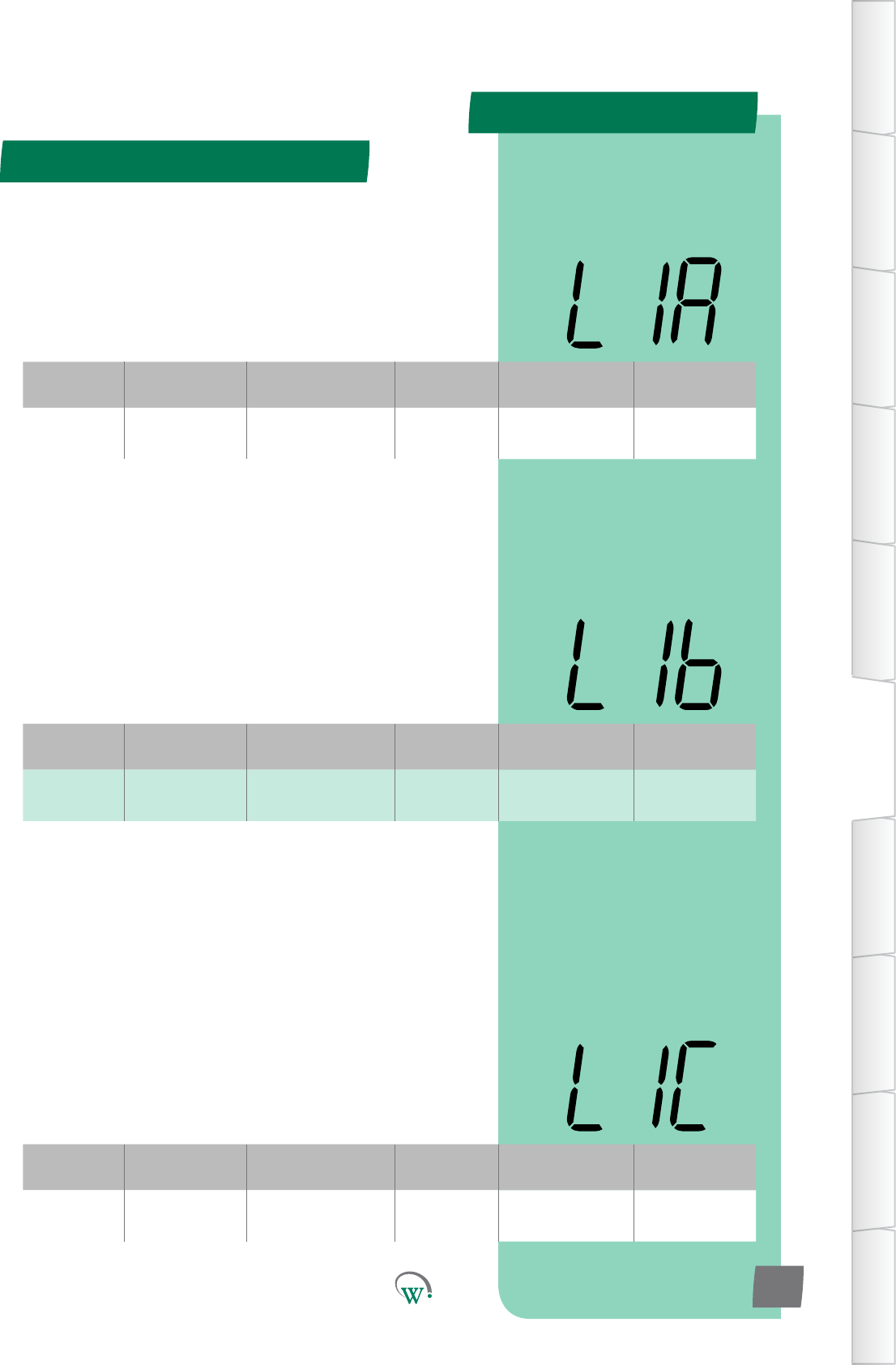
L1A Lighng&
Display 0% to 100% 1% 50% LSA, L1b, L1C
LIGHT STATE TRANSITION 1MODE–CHANNELB (L1b)
TheilluminaonlevelduringTransion1ModeofChannelBas
apercentageoffullilluminaon.
Note:Lightlevelsofbetween0%and100%areonlyavailable
ifChannelBisassignedtoanLEDoutput.Ifassignedtoa
digitaloutput,thenanylevelotherthan0%willresultin100%
illuminaonlevel.
LIGHT STATE TRANSITION 1MODE–CHANNELC (L1C)
TheilluminaonlevelduringTransion1ModeofChannelCas
apercentageoffullilluminaon.
Note:Lightlevelsofbetween0%and100%areonlyavailable
ifChannelCisassignedtoanLEDoutput.Ifassignedtoa
digitaloutput,thenanylevelotherthan0%willresultin100%
illuminaonlevel.
Digital
Display
Funconal
Category ParameterRange Increments
&Units Default Related Menus
L1b Lighng&
Display 0% to 100% 1% 50% LSA, L1A, L1C
Digital
Display
Funconal
Category ParameterRange Increments
&Units Default Related Menus
L1C Lighng&
Display 0% to 100% 1% 50% LSA, L1A, L1b
Transion 1 Mode (tn1) - cont
TABLE OF
CONTENTS
INTRODUCTION
& WARNINGS
DESCRIPTION
& INSTALLATION
FRONT PANEL
USER INTERFACE
GRAPHICAL
USER INTERFACE
PARAMETERS
UPGRADING
FIRMWARE
FAULTS &
ALARMS
TECHNICAL
SPECIFICATION
APPENDICES
PD0006 V2.0 – 08 Jan 2016 35
LIGHT STATE TRANSITION 1MODE–CHANNELA (L1A)
TheilluminaonlevelduringTransion1ModeofChannelAas
apercentageoffullilluminaon.
Note:Lightlevelsofbetween0%and100%areonlyavailable
ifChannelAisassignedtoanLEDoutput.Ifassignedtoa
digitaloutput,thenanylevelotherthan0%willresultin100%
illuminaonlevel.
PARAMETERS
Parameter Name Digital
Display Pages Increments
&Units Range Default
TEMPERATURE
Transion2SetPoint tS2 37 0.1 °C -10.0 to 15.0 °C 7.0 °C
Transion2Dierenal td2 37 0.1 °C 0.1 to 10.0 °C 2.0 °C
TIME
InacvityWaitTime-
Transion2 yt2 37 0.5 hours 0.0 to 24.0 hours 1 hour
LIGHTING & DISPLAY
LightStateTransion2
Mode - Channel A L2A 38 1% 0% to 100% 0%
LightStateTransion2
Mode - Channel B L2b 38 1% 0% to 100% 0%
LightStateTransion2
Mode - Channel C L2C 38 1% 0% to 100% 0%
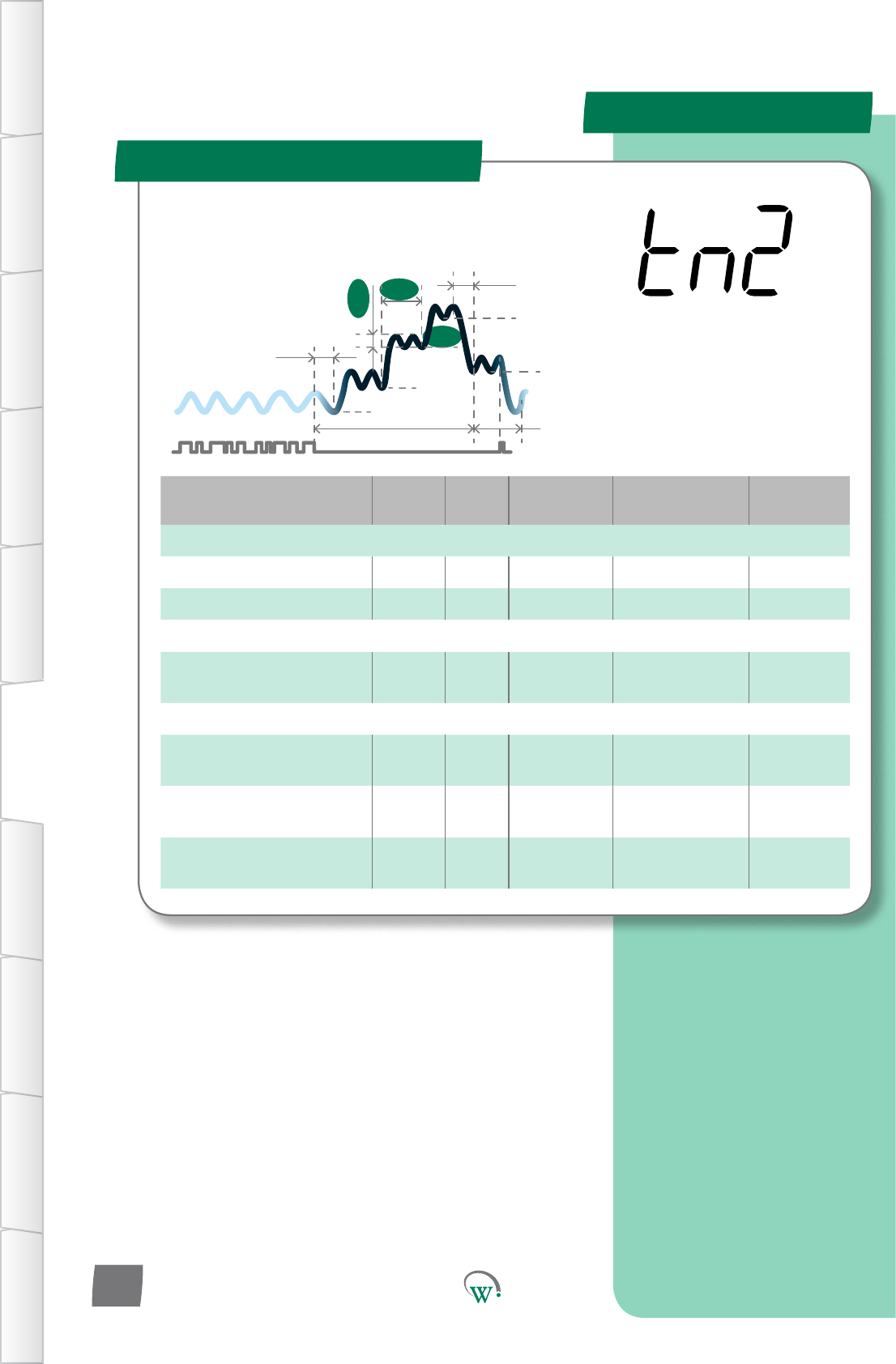
Transion 2 Mode (tn2)
SP
tS1
Sbt
tS2
Ytn
SSP
Pdt
yt3
td2
tS3
yt2
TABLE OF
CONTENTS
INTRODUCTION
& WARNINGS
DESCRIPTION
& INSTALLATION
FRONT PANEL
USER INTERFACE
GRAPHICAL
USER INTERFACE PARAMETERS UPGRADING
FIRMWARE
FAULTS &
ALARMS
TECHNICAL
SPECIFICATION APPENDICES
PD0006 V2.0 – 08 Jan 2016
36
TheTransionModesareusedtominimizePulldownmes.
Transionalsetpointtemperaturesareusedthatarein
betweentheOperaonalSetPointandfullStandbySetPoint.
TheTransionModesmaybe
most useful if the retail outlet
openinghoursvary,orifcustomer
demandvaries,suchthataregular
Pulldownmeisuncertain.
PARAMETERS
Digital
Display
Funconal
Category ParameterRange Increments
&Units Default Related Menus
tS2 Temperature -10.0 to 15.0 °C 0.1 °C 7.0 °C td2
Digital
Display
Funconal
Category ParameterRange Increments
&Units Default Related Menus
td2 Temperature 0.1 to 10.0 °C 0.1 °C 2.0 °C tS2
Digital
Display
Funconal
Category ParameterRange Increments
&Units Default Related Menus
yt2 Time 0 to 24 hours 0.5 hours 1 hour yt1, Ytn
Transion 2 Mode (tn2) - cont
TABLE OF
CONTENTS
INTRODUCTION
& WARNINGS
DESCRIPTION
& INSTALLATION
FRONT PANEL
USER INTERFACE
GRAPHICAL
USER INTERFACE
PARAMETERS
UPGRADING
FIRMWARE
FAULTS &
ALARMS
TECHNICAL
SPECIFICATION
APPENDICES
PD0006 V2.0 – 08 Jan 2016 37
TRANSITION 2 SET POINT (tS2)
ThetemperatureatwhichtheCompressorwillturno,when
thesystemisrunninginTransion2Mode.Transion2Mode
is the second step in the Standby process to conserve power
duringprolongedperiodsofinacvity.
TRANSITION 2 DIFFERENTIAL (td2)
ThetemperatureabovetheTransion2SetPoint(tS2)
temperature, which will cause the Compressor to turn on
wheninTransion2Mode.TheCompressorwillremainon
unlthetemperaturereachestheTransion2SetPoint(tS2)
temperature.
Turn On Temperature = tS2 + td2
INACTIVITY WAIT TIME - TRANSITION 2 (yt2)
ThemaximummepermiedinTransion2Modewithoutany
detectedacvity,beforeswitchingtofullStandbyMode.
PARAMETERS
Digital
Display
Funconal
Category ParameterRange Increments
&Units Default Related Menus
L2A Lighng&
Display 0% to 100% 1% 0% LSA, L2b, L3A
Digital
Display
Funconal
Category ParameterRange Increments
&Units Default Related Menus
L2b Lighng&
Display 0% to 100% 1% 0% LSA, L2A, L2C
Digital
Display
Funconal
Category ParameterRange Increments
&Units Default Related Menus
L2C Lighng&
Display 0% to 100% 1% 0% LSA, L2A, L2b
LIGHT STATE TRANSITION 2MODE–CHANNELA (L2b)
TheilluminaonlevelduringTransion2ModeofChannelBas
apercentageoffullilluminaon.
Note:Lightlevelsofbetween0%and100%areonlyavailable
ifChannelBisassignedtoanLEDoutput.Ifassignedtoa
digitaloutput,thenanylevelotherthan0%willresultin100%
illuminaonlevel.
LIGHT STATE TRANSITION 2MODE–CHANNELA (L2C)
TheilluminaonlevelduringTransion2ModeofChannelCas
apercentageoffullilluminaon.
Note:Lightlevelsofbetween0%and100%areonlyavailable
ifChannelCisassignedtoanLEDoutput.Ifassignedtoa
digitaloutput,thenanylevelotherthan0%willresultin100%
illuminaonlevel.
Transion 2 Mode (tn2) - cont
TABLE OF
CONTENTS
INTRODUCTION
& WARNINGS
DESCRIPTION
& INSTALLATION
FRONT PANEL
USER INTERFACE
GRAPHICAL
USER INTERFACE PARAMETERS UPGRADING
FIRMWARE
FAULTS &
ALARMS
TECHNICAL
SPECIFICATION APPENDICES
PD0006 V2.0 – 08 Jan 2016
38
LIGHT STATE TRANSITION 2MODE–CHANNELA (L2A)
TheilluminaonlevelduringTransion2ModeofChannelAas
apercentageoffullilluminaon.
Note:Lightlevelsofbetween0%and100%areonlyavailable
ifChannelAisassignedtoanLEDoutput.Ifassignedtoa
digitaloutput,thenanylevelotherthan0%willresultin100%
illuminaonlevel.
PARAMETERS
Parameter Name Digital
Display Pages Increments
&Units Range Default
TEMPERATURE
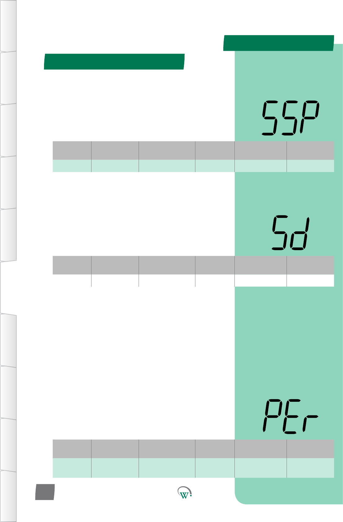
Standby Set Point SSP 40 0.1 °C -10.0 to 15.0 °C 8.5 °C
StandbyDierenal Sd 40 0.1 °C 0.1 to 10.0 °C 2.0 °C
Perishable Mode PEr 40 text on or oFF oFF
TIMERS & COUNTERS
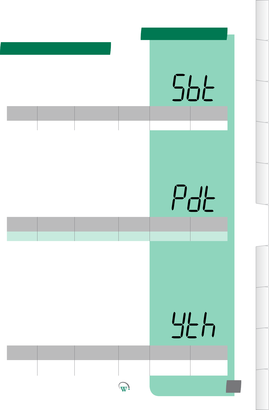
Maximum Standby Time Sbt 41 0.5 hour 0.0 to 24.0 hours 10 hours
Pulldown Time Pdt 41 0.5 hour 0.0 to 12.0 hours 1 hours
InacvityWaitTime-
Standby Hold yth 41 0.5 hours 0.0 to 24.0 hours
orinnite 4 hours
LIGHTING & DISPLAY
LightStateStandbyMode
- Channel A LSA 42 1% 0% to 100% 0%
LightStateStandbyMode
- Channel B LSb 42 1% 0% to 100% 0%
LightStateStandbyMode
- Channel C LSC 42 1% 0% to 100% 0%
DisplayControlDuring
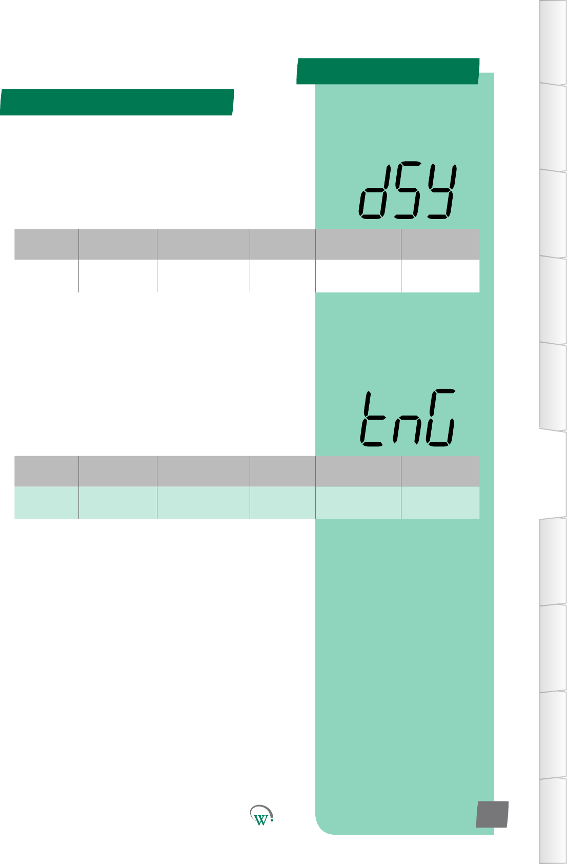
Standby Mode dSy 43 integers 0 0
MarkengMode tnG 43 text on or oFF
or c01 oFF
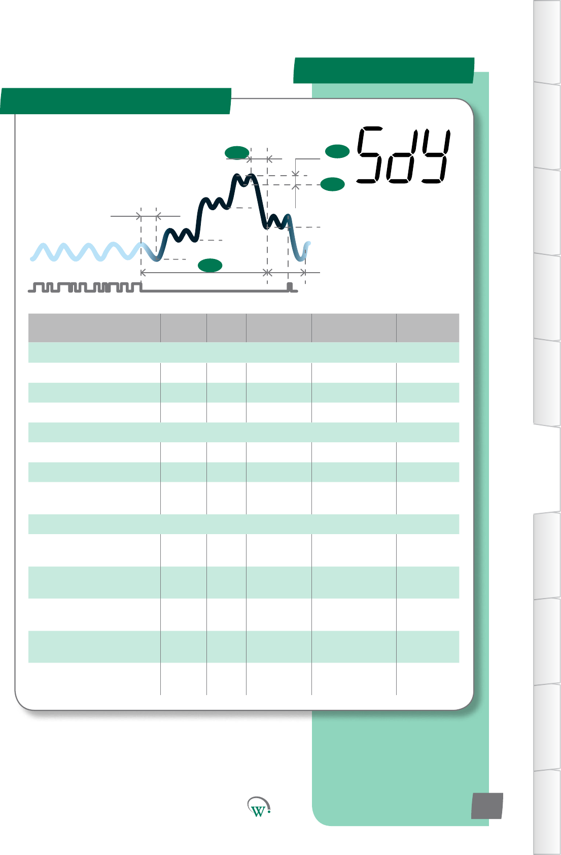
Standby Mode (SdY)
SP
tS1
Sbt
tS2
Ytn
SSP
Sd
Pdt
yt3
tS3
TABLE OF
CONTENTS
INTRODUCTION
& WARNINGS
DESCRIPTION
& INSTALLATION
FRONT PANEL
USER INTERFACE
GRAPHICAL
USER INTERFACE
PARAMETERS
UPGRADING
FIRMWARE
FAULTS &
ALARMS
TECHNICAL
SPECIFICATION
APPENDICES
PD0006 V2.0 – 08 Jan 2016 39
The Standby Modes are an
intelligentmethodtosavepower
whentheCoolersarenotbeing
accessedbycustomers,generally
outside of normal business hours.
The SCS Connect can
managethisprocessto
minimizethePulldown
mewhenbusinessesre-
open,oritcanmaximize
energysavingsoverall.
PARAMETERS
Digital
Display
Funconal
Category ParameterRange Increments
&Units Default Related Menus
SSP Temperature -10.0 to 15.0 °C 0.1 °C 8.5 °C Sd
Digital
Display
Funconal
Category ParameterRange Increments
&Units Default Related Menus
Sd Temperature 0.1 to 10.0 °C 0.1 °C 2.0 °C SSP
Digital
Display
Funconal
Category ParameterRange Increments
&Units Default Related Menus
PEr Temperature on or oFF text oFF SP, SP-, SPt, LnA,
htA
Standby Mode (SdY) - cont
TABLE OF
CONTENTS
INTRODUCTION
& WARNINGS
DESCRIPTION
& INSTALLATION
FRONT PANEL
USER INTERFACE
GRAPHICAL
USER INTERFACE PARAMETERS UPGRADING
FIRMWARE
FAULTS &
ALARMS
TECHNICAL
SPECIFICATION APPENDICES
PD0006 V2.0 – 08 Jan 2016
40
STANDBY SET POINT (SSP)
ThetemperatureatwhichtheCompressorwillturno,when
thesystemisrunninginStandbyMode.TheStandbyModes
areasequenceofsengsthatprogressivelyconservepower
duringprolongedperiodsofinacvity.Themul-stepprocess
meetstworequirements;itconservespoweranditbrings
the product in the cabinet back to the correct temperature as
quicklyaspossiblewhensalesacvityrestarts.
STANDBY DIFFERENTIAL (Sd)
The temperature above the Standby Set Point (SSP)
temperature, which will cause the Compressor to turn on when
inStandbyMode.TheCompressorwillremainonunlthe
temperature reaches the Standby Set Point (SSP) temperature.
Compressor Turn On Temperature = SSP + Sd
PERISHABLE MODE (PEr)
Selects whether or not the product in the cabinet must remain
coldatallmes.Thisisrequiredforcertainfoodstusand
medicines,suchasthoseunderHACCPregulaons.Ifthis
funconissetto‘on’,allTemperatureandEvaporatorsengs
will use the Normal Mode values to maintain the temperature
attheOperaonalSetPoint(SP)temperature.Allother
parameters(suchasLightsandDisplay)willusetheTransion
ModeandStandbyModesengs.
Note:Pulldownmewillbeoverriddentozero,astheproduct
will remain at temperature.
on=ProductkeptatSetPointTemperature.Standby&
TransionModescontrolLightsonly.
oFF = Runs in Normal Mode.
PARAMETERS
Digital
Display
Funconal
Category ParameterRange Increments
&Units Default Related Menus
Pdt Time 0 to 12 hours 0.5 hour 1 hours Sbt, SP, tS3
Digital
Display
Funconal
Category ParameterRange Increments
&Units Default Related Menus
Sbt Time 0 to 24 hours 0.5 hour 10 hours Pdt
Digital
Display
Funconal
Category ParameterRange Increments
&Units Default Related Menus
yth Time 0 to 24 hours
or InFinite 0.5 hours 4 hours
INACTIVITY WAIT TIME - STANDBY HOLD (yth)
Themethesystemwillremaininstandbywithnoacvity
beforetransioningbacktoTransion3Mode.
Note:
If OCS = 0, the system will instantly return to Normal Mode
IfOCS>0andtheOCSmeisreachedwithoutanacvitythen:
IfT3>0,ThesystemwillreturntoTransion3Mode
If T3 = 0, the system will return to Normal Mode
IfOCS=inf,thesystemwillremainindeniatelyinstandbyunl
anacvityisseen
Standby Mode (SdY) - cont
TABLE OF
CONTENTS
INTRODUCTION
& WARNINGS
DESCRIPTION
& INSTALLATION
FRONT PANEL
USER INTERFACE
GRAPHICAL
USER INTERFACE
PARAMETERS
UPGRADING
FIRMWARE
FAULTS &
ALARMS
TECHNICAL
SPECIFICATION
APPENDICES
PD0006 V2.0 – 08 Jan 2016 41
MAXIMUM STANDBY TIME (Sbt)
Themaximummepermissibleforthesystemtoremainin
standbywithoutanydetectedacvity.PullDownsarestartedto
ensurethattheproductinthecabinetreachestheTransion3
Set Point (tS3) within Maximum Standby Time (Sbt) hours from
thelastdetectedacvity.
PULLDOWN TIME (Pdt)
Themaximummeitwilltakefortheproductinthecabinet
toreacheither;OperaonalSetPoint(SP),orifitisused
Transion3SetPoint(tS3),aerleavingStandbyMode.This
parameter is used to determine when the Pulldown should
commence to ensure that the product is at the correct
temperature when the store opens at the start of the day.
PARAMETERS
Digital
Display
Funconal
Category ParameterRange Increments
&Units Default Related Menus
LSA Lighng&
Display 0% to 100% 1% 0% LnA, LSb, LSC
Digital
Display
Funconal
Category ParameterRange Increments
&Units Default Related Menus
LSb Lighng&
Display 0% to 100% 1% 0% LnA, LSA, LSC
Digital
Display
Funconal
Category ParameterRange Increments
&Units Default Related Menus
LSC Lighng&
Display 0% to 100% 1% 0% LnA, LSA, LSb
LIGHT STATE STANDBYMODE–CHANNELB (LSb)
TheilluminaonlevelduringStandbyModeofChannelBasa
percentageoffullilluminaon.
Note:Lightlevelsofbetween0%and100%areonlyavailable
ifChannelBisassignedtoanLEDoutput.Ifassignedtoa
digitaloutput,thenanylevelotherthan0%willresultin100%
illuminaonlevel.
LIGHT STATE STANDBYMODE–CHANNELC (LSC)
TheilluminaonlevelduringStandbyModeofChannelCasa
percentageoffullilluminaon.
Note:Lightlevelsofbetween0%and100%areonlyavailable
ifChannelCisassignedtoanLEDoutput.Ifassignedtoa
digitaloutput,thenanylevelotherthan0%willresultin100%
illuminaonlevel.
Standby Mode (SdY) - cont
TABLE OF
CONTENTS
INTRODUCTION
& WARNINGS
DESCRIPTION
& INSTALLATION
FRONT PANEL
USER INTERFACE
GRAPHICAL
USER INTERFACE PARAMETERS UPGRADING
FIRMWARE
FAULTS &
ALARMS
TECHNICAL
SPECIFICATION APPENDICES
PD0006 V2.0 – 08 Jan 2016
42
LIGHT STATE STANDBYMODE–CHANNELA (LSA)
TheilluminaonlevelduringStandbyModeofChannelAasa
percentageoffullilluminaon.
Note:Lightlevelsofbetween0%and100%areonlyavailable
ifChannelAisassignedtoanLEDoutput.Ifassignedtoa
digitaloutput,thenanylevelotherthan0%willresultin100%
illuminaonlevel.
PARAMETERS
Digital
Display
Funconal
Category ParameterRange Increments
&Units Default Related Menus
dSy Lighng&
Display 0integers 0 SSP
Digital
Display
Funconal
Category ParameterRange Increments
&Units Default Related Menus
tnG Lighng&
Display
on or oFF
or c01 text oFF LnA, LSA, L1A,
L2A, L3A
Standby Mode (SdY) - cont
TABLE OF
CONTENTS
INTRODUCTION
& WARNINGS
DESCRIPTION
& INSTALLATION
FRONT PANEL
USER INTERFACE
GRAPHICAL
USER INTERFACE
PARAMETERS
UPGRADING
FIRMWARE
FAULTS &
ALARMS
TECHNICAL
SPECIFICATION
APPENDICES
PD0006 V2.0 – 08 Jan 2016 43
DISPLAY CONTROL DURING STANDBY MODE (dSy)
SelectswhatisdisplayedduringfullStandbyMode:
0 = Displays the temperature.
1* = Displays the Set Point Temperature.
2*=Displayisleblank.
* Not yet enabled
MARKETING MODE (tnG)
Selectswhetherornotthelightsstayonatallmes.
on=LightlevelsandeectsduringTransionandStandby
ModescontrolledbyNormalModesengs.
o=LightlevelsandeectscontrolledbythecurrentMode
sengs.
c01=Customseng01.All3LEDlighngchannelscycle
connuouslyfrom0to100%.UsedforRGBlighngtocycle
colours.Doorstateandmodeisignored
PARAMETERS
Parameter Name Digital
Display Pages Increments
&Units Range Default
TEMPERATURE
Transion3SetPoint tS3 45 0.1 °C -10.0 to 15.0 °C 5.5 °C
Transion3Dierenal td3 45 0.1 °C 0.1 to 10.0 °C 2.0 °C
TIME
InacvityWaitTime-
Transion3 yt3 45 0.5 hours 0.0 to 24.0 hours 1 hour
LIGHTING & DISPLAY
LightStateTransion3
Mode - Channel A L3A 46 1% 0% to 100% 0%
LightStateTransion3
Mode - Channel B L3b 46 1% 0% to 100% 0%
LightStateTransion3
Mode - Channel C L3C 46 1% 0% to 100% 0%
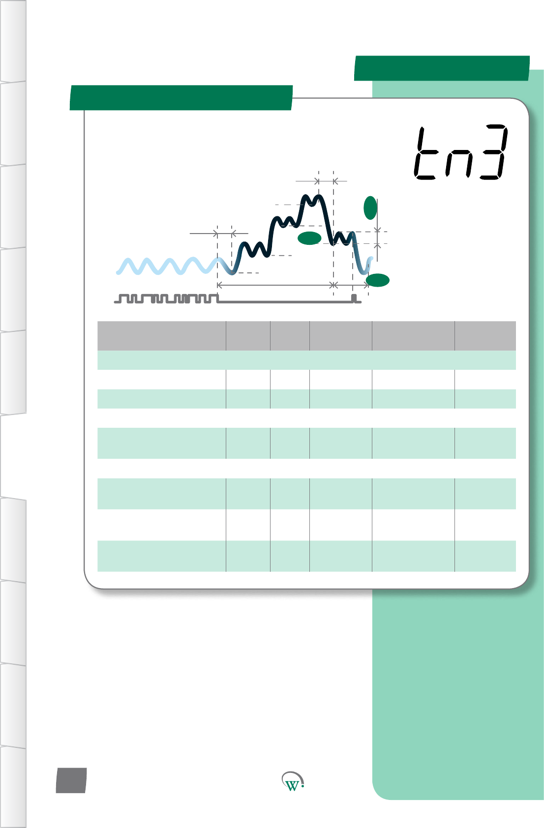
Transion 3 Mode (tn3)
SP
tS1
Sbt
tS2
Ytn
SSP
Pdt
yt3
td3
tS3
TABLE OF
CONTENTS
INTRODUCTION
& WARNINGS
DESCRIPTION
& INSTALLATION
FRONT PANEL
USER INTERFACE
GRAPHICAL
USER INTERFACE PARAMETERS UPGRADING
FIRMWARE
FAULTS &
ALARMS
TECHNICAL
SPECIFICATION APPENDICES
PD0006 V2.0 – 08 Jan 2016
44
TheTransionModesareusedto
minimizePulldownmes.Transion
3 Mode is an intermediate set point
temperature in between the Standby
SetPointandtheOperaonalSetPoint.
TheTransionModes
may be most useful if
theretailoutletopening
hours vary, or if customer
demand varies, such that
aregularPulldownmeis
uncertain.
PARAMETERS
Digital
Display
Funconal
Category ParameterRange Increments
&Units Default Related Menus
td3 Temperature 0.1 to 10.0 °C 0.1 °C 2.0 °C tS3
Digital
Display
Funconal
Category ParameterRange Increments
&Units Default Related Menus
yt3 Time 0 to 24 hours 0.5 hours 1 hour Pdt
Digital
Display
Funconal
Category ParameterRange Increments
&Units Default Related Menus
tS3 Temperature -10.0 to 15.0 °C 0.1 °C 5.5 °C td3
Transion 3 Mode (tn3) - cont
TABLE OF
CONTENTS
INTRODUCTION
& WARNINGS
DESCRIPTION
& INSTALLATION
FRONT PANEL
USER INTERFACE
GRAPHICAL
USER INTERFACE
PARAMETERS
UPGRADING
FIRMWARE
FAULTS &
ALARMS
TECHNICAL
SPECIFICATION
APPENDICES
PD0006 V2.0 – 08 Jan 2016 45
TRANSITION 3 DIFFERENTIAL (td3)
ThetemperatureabovetheTransion3SetPoint(tS3)
temperature, which will cause the Compressor to turn on
wheninTransion3Mode.TheCompressorwillremainon
unlthetemperaturereachestheTransion3SetPoint(tS3)
temperature.
Turn On Temperature = tS3 + td3
INACTIVITY WAIT TIME - TRANSITION 3 (yt3)
ThemaximummepermiedinTransion3Modewithoutany
detectedacvity,beforeswitchingtofullStandbyMode.
TRANSITION 3 SET POINT (tS3)
ThetemperatureatwhichtheCompressorwillturno,when
thesystemisrunninginTransion3Mode.Transion3
Mode an intermediate step between Standby Set Point and
OperaonalSetPoint,andisusedtoconservepowerinthe
eventthatthereisnosalesacvitydetected.
PARAMETERS
Digital
Display
Funconal
Category ParameterRange Increments
&Units Default Related Menus
L3A Lighng&
Display 0% to 100% 1% 0% LSA, L3b, L3C
Digital
Display
Funconal
Category ParameterRange Increments
&Units Default Related Menus
L3b Lighng&
Display 0% to 100% 1% 0% LSA, L3A, L3C
Digital
Display
Funconal
Category ParameterRange Increments
&Units Default Related Menus
L3C Lighng&
Display 0% to 100% 1% 0% LSA, L3A, L3b
LIGHT STATE TRANSITION 3MODE–CHANNELB (L3b)
TheilluminaonlevelduringTransion3ModeofChannelBas
apercentageoffullilluminaon.
Note:Lightlevelsofbetween0%and100%areonlyavailable
ifChannelBisassignedtoanLEDoutput.Ifassignedtoa
digitaloutput,thenanylevelotherthan0%willresultin100%
illuminaonlevel.
LIGHT STATE TRANSITION 3MODE–CHANNELC (L3C)
TheilluminaonlevelduringTransion3ModeofChannelCas
apercentageoffullilluminaon.
Note:Lightlevelsofbetween0%and100%areonlyavailable
ifChannelCisassignedtoanLEDoutput.Ifassignedtoa
digitaloutput,thenanylevelotherthan0%willresultin100%
illuminaonlevel.
Transion 3 Mode (tn3) - cont
TABLE OF
CONTENTS
INTRODUCTION
& WARNINGS
DESCRIPTION
& INSTALLATION
FRONT PANEL
USER INTERFACE
GRAPHICAL
USER INTERFACE PARAMETERS UPGRADING
FIRMWARE
FAULTS &
ALARMS
TECHNICAL
SPECIFICATION APPENDICES
PD0006 V2.0 – 08 Jan 2016
46
LIGHT STATE TRANSITION 3MODE–CHANNELA (L3A)
TheilluminaonlevelduringTransion3ModeofChannelAas
apercentageoffullilluminaon.
Note:Lightlevelsofbetween0%and100%areonlyavailable
ifChannelAisassignedtoanLEDoutput.Ifassignedtoa
digitaloutput,thenanylevelotherthan0%willresultin100%
illuminaonlevel.
PARAMETERS
Parameter Name Digital
Display Pages Increments
&Units Range Default
TEMPERATURE
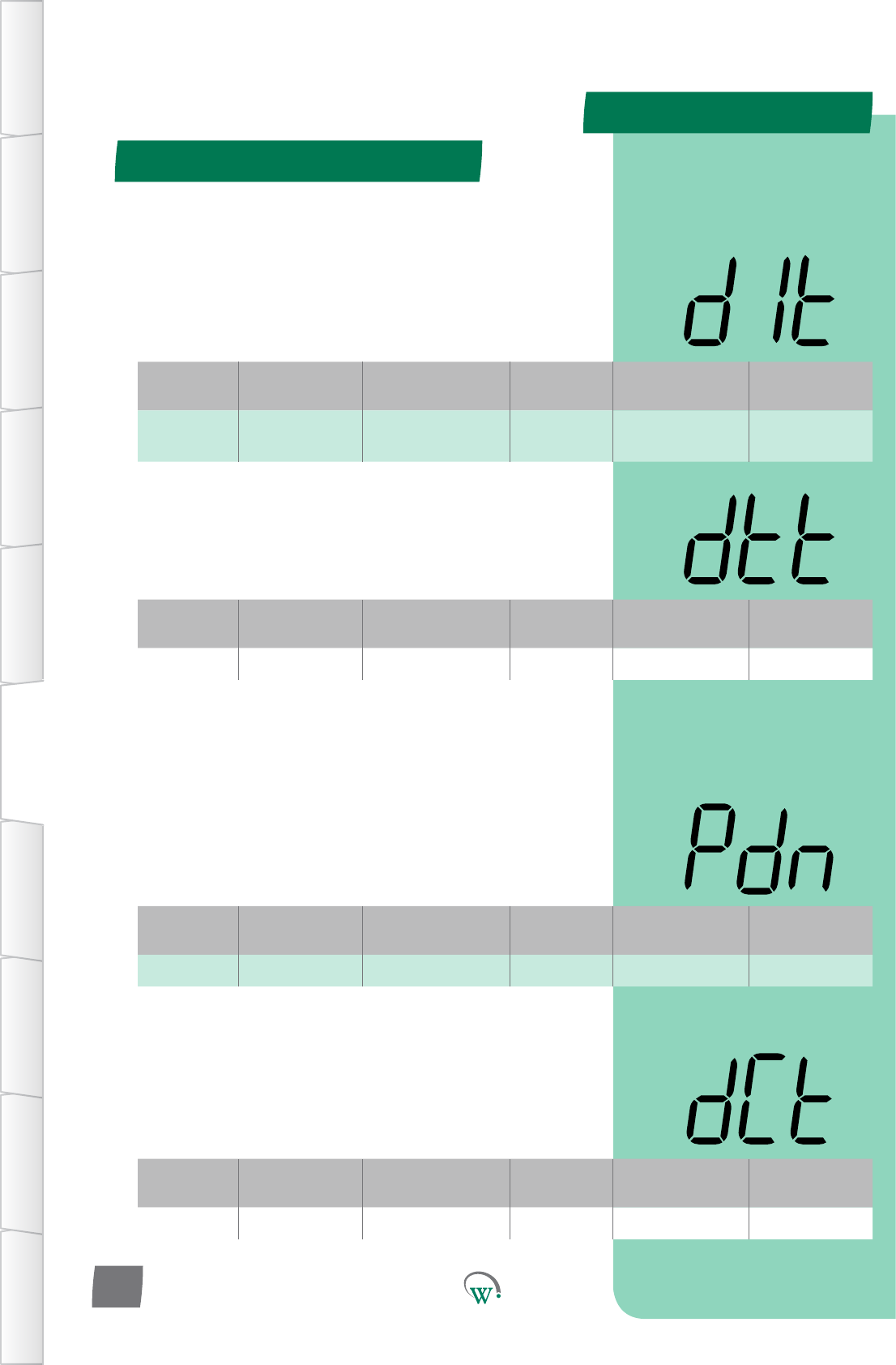
DefrostIniaon
Temperature dIt 48 1°C -15 to 10°C
or dISabled dISabled
DefrostTerminaon
Temperature d 48 1°C 0 to 30°C 10°C
Uninterrupted Pull Down
Temperature Pdn 48 1 °C dISabled dISabled
TIME
Maximum Defrost Cycle
Time dCt 48 1 min 1 to 30 mins 10 mins
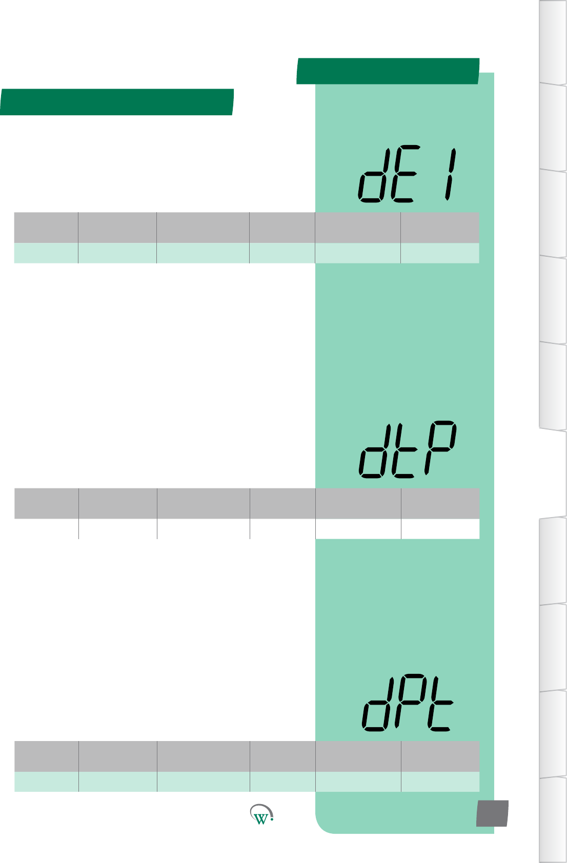
Maximum Defrost Interval dEI 49 1 hour 1 to 48 hours 3 hours
Defrost Type dtP 49 integers 0 - 3 3
DrippingTime dPt 49 1 min 0 to 30 mins 0 min
LIGHTING & DISPLAY
DisplayValueDuringDefrost
Cycle ddE 50 integers 3 3
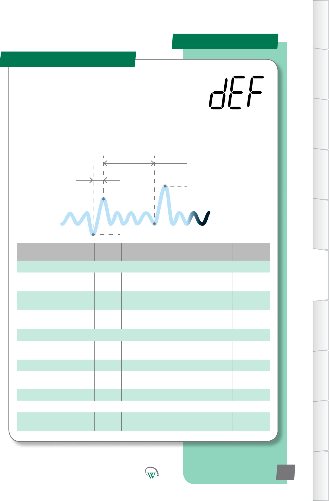
Defrost Mode (dEF)
DefrostIniaonTemperature(dIt)
Defrost Cycle
Time (dCt)
Maximum
Defrost
Interval (dEI)
DefrostTerminaon
Temperature(d)
TABLE OF
CONTENTS
INTRODUCTION
& WARNINGS
DESCRIPTION
& INSTALLATION
FRONT PANEL
USER INTERFACE
GRAPHICAL
USER INTERFACE
PARAMETERS
UPGRADING
FIRMWARE
FAULTS &
ALARMS
TECHNICAL
SPECIFICATION
APPENDICES
PD0006 V2.0 – 08 Jan 2016 47
TheDefrostCyclecanbeiniatedorterminatedbyeither
meortemperature.DuringtheDefrostCycletheNormal
OperaonalModeisoverriddentocontroltheCompressor,
EvaporatorFan,Lights,andifused,anyvalvesorheater
elements connected to the Relay.
SupportedDefrostCyclemethodsare;hotgasdefrost(reverse
cycle),ambientdefrost(withthecompressorturnedo),and
a forced defrost (with an electric heater element).
Theseparametersprovidetheoponstocontroland
conguretheDefrostCycle.
PARAMETERS
Defrost Mode (dEF) - cont
TABLE OF
CONTENTS
INTRODUCTION
& WARNINGS
DESCRIPTION
& INSTALLATION
FRONT PANEL
USER INTERFACE
GRAPHICAL
USER INTERFACE PARAMETERS UPGRADING
FIRMWARE
FAULTS &
ALARMS
TECHNICAL
SPECIFICATION APPENDICES
PD0006 V2.0 – 08 Jan 2016
48
Digital
Display
Funconal
Category ParameterRange Increments
&Units Default Related Menus
dIt Temperature -15 to 10°C
or dISabled 1°C dISabled d,dCt
DEFROST INITIATION TEMPERATURE (dIt)
ThetemperaturebelowwhichaDefrostcyclewillbeiniated.
ThecyclewillrununleithertheDefrostTerminaon
Temperature(d)isreached,ortheDefrostCycleTime(dCt)is
met.OperaonisdependentuponthesengsinDefrostType
(dtP)
Digital
Display
Funconal
Category ParameterRange Increments
&Units Default Related Menus
d Temperature 0 to 30°C 1°C 10°C dCt, dIt
DEFROST TERMINATION TEMPERATURE(d)
The temperature at which the Defrost Cycle will terminate to
prevent an excessive internal temperature.
Digital
Display
Funconal
Category ParameterRange Increments
&Units Default Related Menus
Pdn Temperature dISabled 1 °C dISabled SSP
* UNINTERRUPTED PULLDOWN TEMPERATURE (Pdn)
The temperature, which if exceeded for over an hour, will
enableaPulldown.DuringPulldown,theCompressorwillrun
connuouslyandDefrostModewillbedisabled.Pulldown
endswhentheOperaonalSetPoint(SP)isreached.
* Not yet enabled
Digital
Display
Funconal
Category ParameterRange Increments
&Units Default Related Menus
dCt Time 1 to 30 mins 1 min 10 mins d
MAXIMUM DEFROST CYCLE TIME (dCt)
ThemaximumallowablemeforaDefrostCycle.This
parameter is used to stop the Defrost Cycle if it hasn’t cut out
earlier due to temperature.
PARAMETERS
Defrost Mode (dEF) - cont
TABLE OF
CONTENTS
INTRODUCTION
& WARNINGS
DESCRIPTION
& INSTALLATION
FRONT PANEL
USER INTERFACE
GRAPHICAL
USER INTERFACE
PARAMETERS
UPGRADING
FIRMWARE
FAULTS &
ALARMS
TECHNICAL
SPECIFICATION
APPENDICES
PD0006 V2.0 – 08 Jan 2016 49
Digital
Display
Funconal
Category ParameterRange Increments
&Units Default Related Menus
dEI Time 1 to 48 hours 1 hour 3 hours dCt, dIt
MAXIMUM DEFROST INTERVAL (dEI)
ThemaximumpermiedmebetweenthenishofaDefrost
Cycle and the start of the next one. This parameter is used
to start the Defrost Cycle if it hasn’t started earlier due to
temperature.
Digital
Display
Funconal
Category ParameterRange Increments
&Units Default Related Menus
dtP Time 0 - 3 integers 3 dPt, dFS
DEFROST TYPE (dtP)
Selects which defrost method is to be used:
0 = Disabled.
1=DefrostCycleusinganelectricheater.
[Defrost ON - Evap OFF - Comp/Cond ON]
2*=DefrostCycleusinghotgas(ReverseCycle).
3=DefrostCyclebyturningotheCompressor(Ambient
Defrost).
[Defrost OFF - Evap ON - Comp/Cond OFF]
* Not yet enabled
Digital
Display
Funconal
Category ParameterRange Increments
&Units Default Related Menus
dPt Time 0 to 30 mins 1 min 0 min dtP
DRIPPING TIME (dPt)
ThemeneededforexcessmoisturetodripotheEvaporator,
tohelppreventfreezeup.Usedforhotgasandelectricheater
defrostsonly.ThiswaitmeoccursaertheDefrosthasbeen
terminatedbyeithermeortemperature,butbeforeexing
theDefrostCycleandreturningtothenon-defrostoperaonal
state.Duringthisme,theEvaporatorFan,CondenserFanand
Compressorremaino.
0 = Disabled.
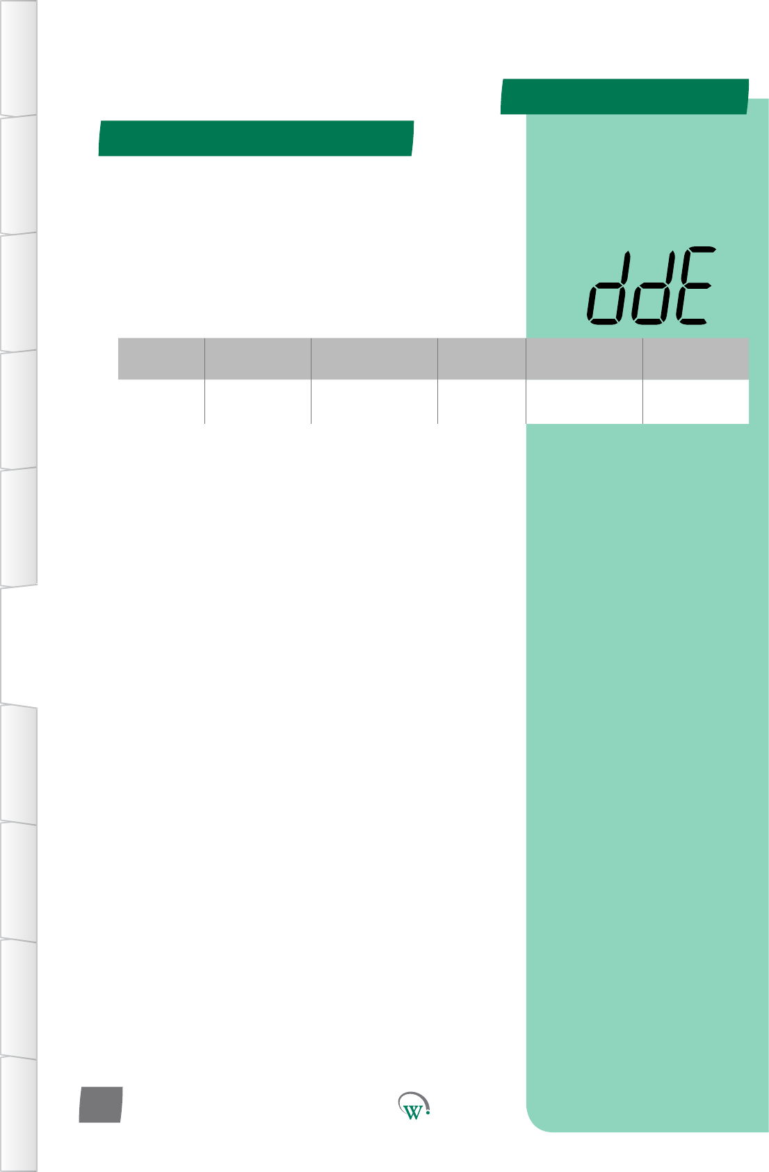
PARAMETERS
Defrost Mode (dEF) - cont
TABLE OF
CONTENTS
INTRODUCTION
& WARNINGS
DESCRIPTION
& INSTALLATION
FRONT PANEL
USER INTERFACE
GRAPHICAL
USER INTERFACE PARAMETERS UPGRADING
FIRMWARE
FAULTS &
ALARMS
TECHNICAL
SPECIFICATION APPENDICES
PD0006 V2.0 – 08 Jan 2016
50
Digital
Display
Funconal
Category ParameterRange Increments
&Units Default Related Menus
ddE Lighng&
Display 0 to 4 integers 3 SP
DISPLAY VALUE DURING DEFROST CYCLE (ddE)
SelectswhatisdisplayedduringtheDefrostCycle:
0* = Displays the temperature.
1* = Displays the Set Point Temperature.
2*=Displayisleblank.
3 = Display shows ‘dEF’.
4*=Displayshows‘dEF’,blinkingintermiently.
* Not yet enabled
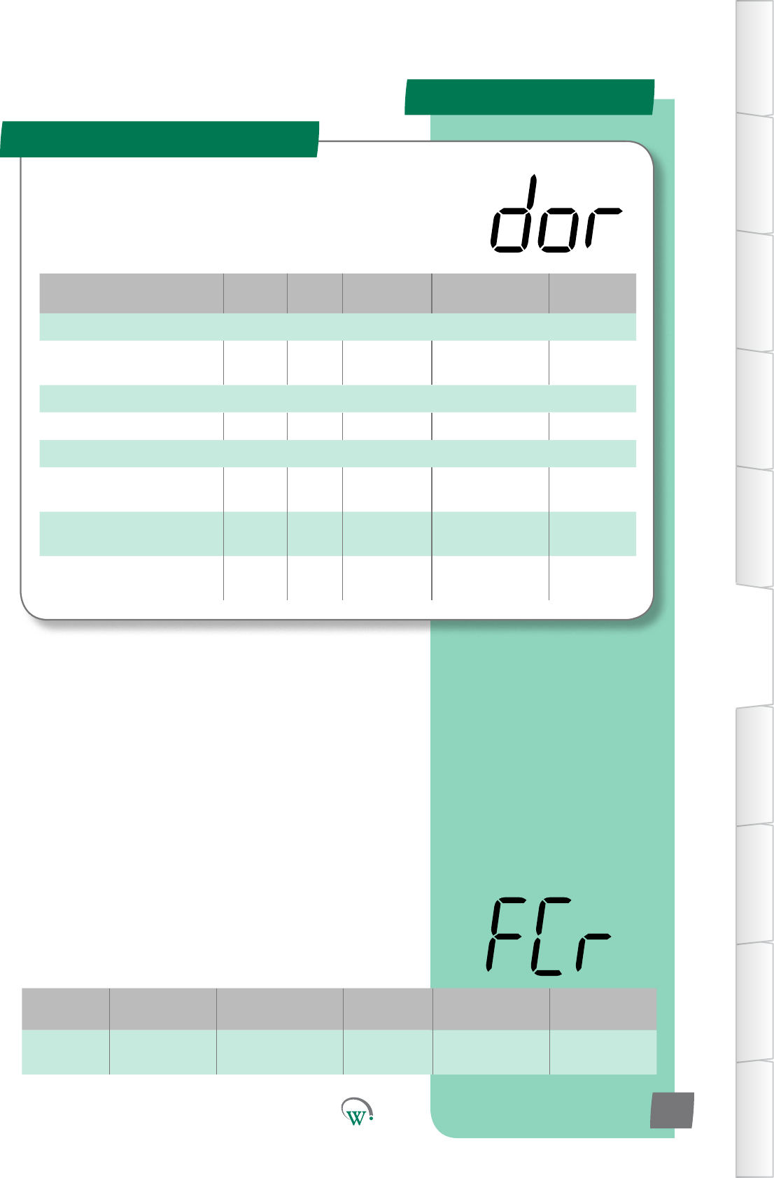
PARAMETERS
Parameter Name Digital
Display Pages Increments
&Units Range Default
TEMPERATURE
DoorOpenEvapConnuous
Run Temp FCr 51 1 °C 0 °C to 30 °C or
dISabled 30 °C
TIME
Door Open Delay drd 52 10 secs 0 to 1800 secs 180 secs
LIGHTING & DISPLAY
LightStateDoorOpen
- Channel A LdA 52 1% 0% to 100%
or dISabled 100%
LightStateDoorOpen
- Channel B Ldb 52 1% 0% to 100%
or dISabled 100%
LightStateDoorOpen
- Channel C LdC 53 1% 0% to 100%
or dISabled 100%
Door Menu (dor)
TABLE OF
CONTENTS
INTRODUCTION
& WARNINGS
DESCRIPTION
& INSTALLATION
FRONT PANEL
USER INTERFACE
GRAPHICAL
USER INTERFACE
PARAMETERS
UPGRADING
FIRMWARE
FAULTS &
ALARMS
TECHNICAL
SPECIFICATION
APPENDICES
PD0006 V2.0 – 08 Jan 2016 51
The SCS Connect uses the cabinet door switch as an input
devicetohelpcontroltheEvaporatorFan,Lightsandto
iniateAlarms.Pleasenote:Shouldthedoorswitchfail,these
parameterswillnotfunconcorrectly.
Digital
Display
Funconal
Category ParameterRange Increments
&Units Default Related Menus
FCr Temperature 0 °C to 30 °C or
dISabled 1 °C 30 °C
DOOR OPEN EVAP CONTINUOUS RUN TEMP (FCr)
The temperature above which the evaporator fan will remain
on, when the cabinet door has been opened, even if the
fanisconguredtobeowhenthecabinetdoorisopened.
Thishelpspreventcondensaonbuildupinhighhumidity
environmentsbyensuringairowinsidethecabinet.
Thiscondionisonlyoverridenwhenindefrostmode
Note:FdCshouldbegreaterthanthestandbysetpoint+
dierenaltoensurenormalfanoperaon.
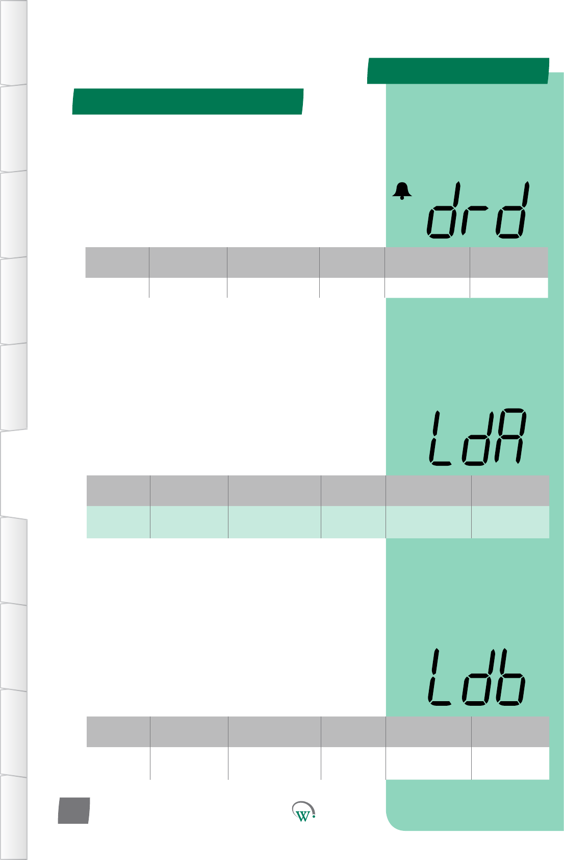
PARAMETERS
Door Menu (dor) - cont
TABLE OF
CONTENTS
INTRODUCTION
& WARNINGS
DESCRIPTION
& INSTALLATION
FRONT PANEL
USER INTERFACE
GRAPHICAL
USER INTERFACE PARAMETERS UPGRADING
FIRMWARE
FAULTS &
ALARMS
TECHNICAL
SPECIFICATION APPENDICES
PD0006 V2.0 – 08 Jan 2016
52
LIGHT STATE DOOROPEN–CHANNELB (Ldb)
TheChannelBilluminaonlevelwhenthedoorisopen,asa
percentageoffullilluminaon.Ifdisabled,thenlightlevelis
unaectedbyopeningthedoor.
Note:Lightlevelsofbetween0%and100%areonlyavailableif
ChannelBisassignedtoanLEDoutput.Ifassignedtoadigital
output,thenanylevelotherthan0%willresultin100%light
level.
Digital
Display
Funconal
Category ParameterRange Increments
&Units Default Related Menus
Ldb Lighng&
Display
0% to 100%
or dISabled 1% 100% LnA, L1A, L2A,
L3A
Digital
Display
Funconal
Category ParameterRange Increments
&Units Default Related Menus
LdA Lighng&
Display
0% to 100%
or dISabled 1% 100% LnA, L1A, L2A,
L3A
LIGHT STATE DOOROPEN–CHANNELA (LdA)
TheChannelAilluminaonlevelwhenthedoorisopen,asa
percentageoffullilluminaon.Ifdisabled,thenlightlevelis
unaectedbyopeningthedoor.
Note:Lightlevelsofbetween0%and100%areonlyavailableif
ChannelAisassignedtoanLEDoutput.Ifassignedtoadigital
output,thenanylevelotherthan0%willresultin100%light
level.
DOOR OPEN DELAY (drd)
Themebetweenthecabinetdooropening(andstayingopen),
andtheDoorOpenAlarmtriggering.
Aerthisme,theevaporatorfanandcompressorwillremain
OFFunleitherthedoorcloses,orthesytemdeterminesthat
the door switch has failed open (10mins).
If the door switch is considered to have failed open, the alarm
willbecleared,andthedoorstateignoredunlacloseddooris
seen.
Digital
Display
Funconal
Category ParameterRange Increments
&Units Default Related Menus
drd Time 0 secs to 1800 secs 10 secs 180 secs drS
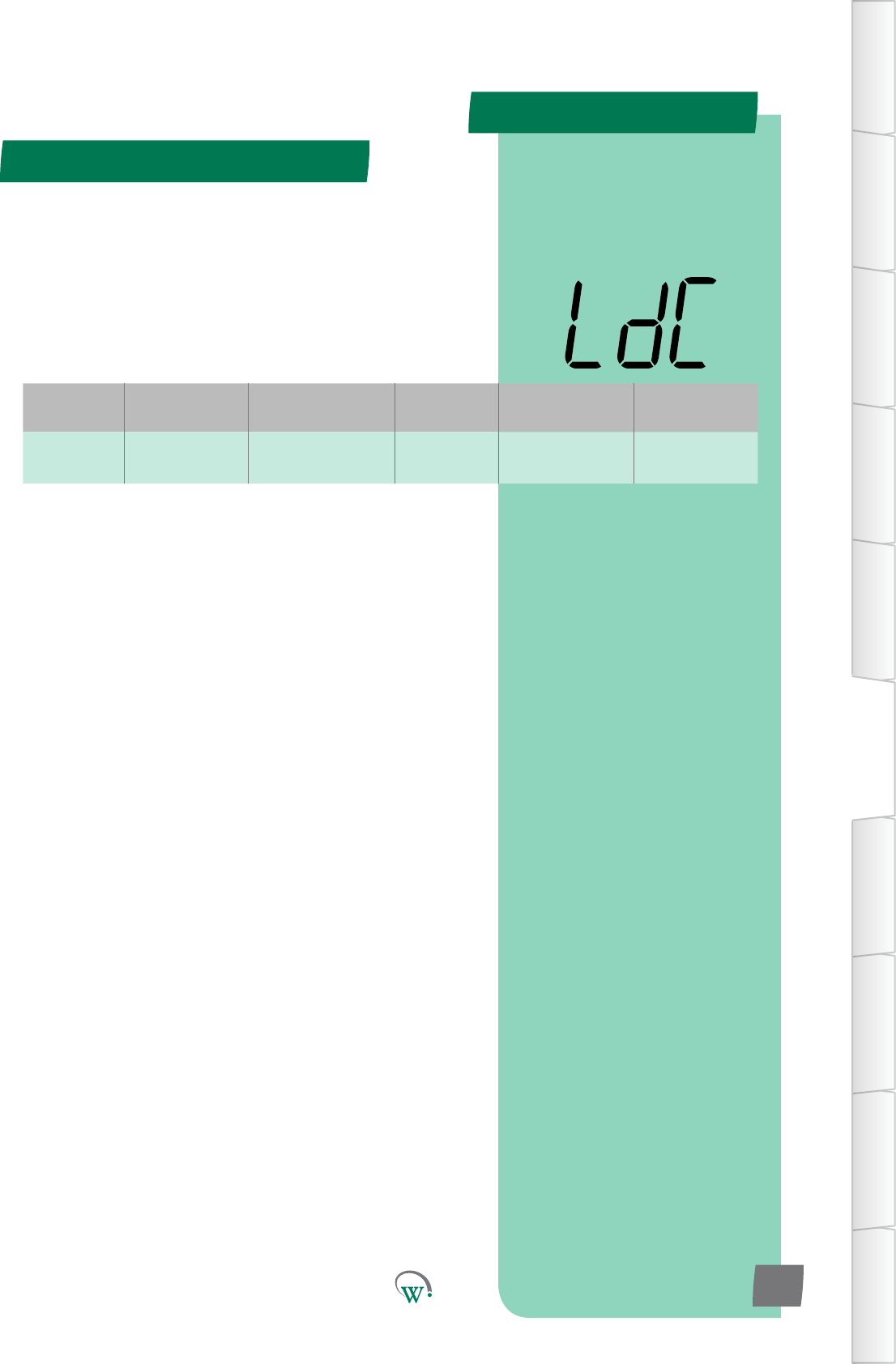
PARAMETERS
Door Menu (dor) - cont
TABLE OF
CONTENTS
INTRODUCTION
& WARNINGS
DESCRIPTION
& INSTALLATION
FRONT PANEL
USER INTERFACE
GRAPHICAL
USER INTERFACE
PARAMETERS
UPGRADING
FIRMWARE
FAULTS &
ALARMS
TECHNICAL
SPECIFICATION
APPENDICES
PD0006 V2.0 – 08 Jan 2016 53
LIGHT STATE DOOROPEN–CHANNELC (LdC)
TheChannelCilluminaonlevelwhenthedoorisopen,asa
percentageoffullilluminaon.Ifdisabled,thenlightlevelis
unaectedbyopeningthedoor.
Note:Lightlevelsofbetween0%and100%areonlyavailableif
ChannelCisassignedtoanLEDoutput.Ifassignedtoadigital
output,thenanylevelotherthan0%willresultin100%light
level.
Digital
Display
Funconal
Category ParameterRange Increments
&Units Default Related Menus
LdC Lighng&
Display
0% to 100%
or dISabled 1% 100% LnA, L1A, L2A,
L3A
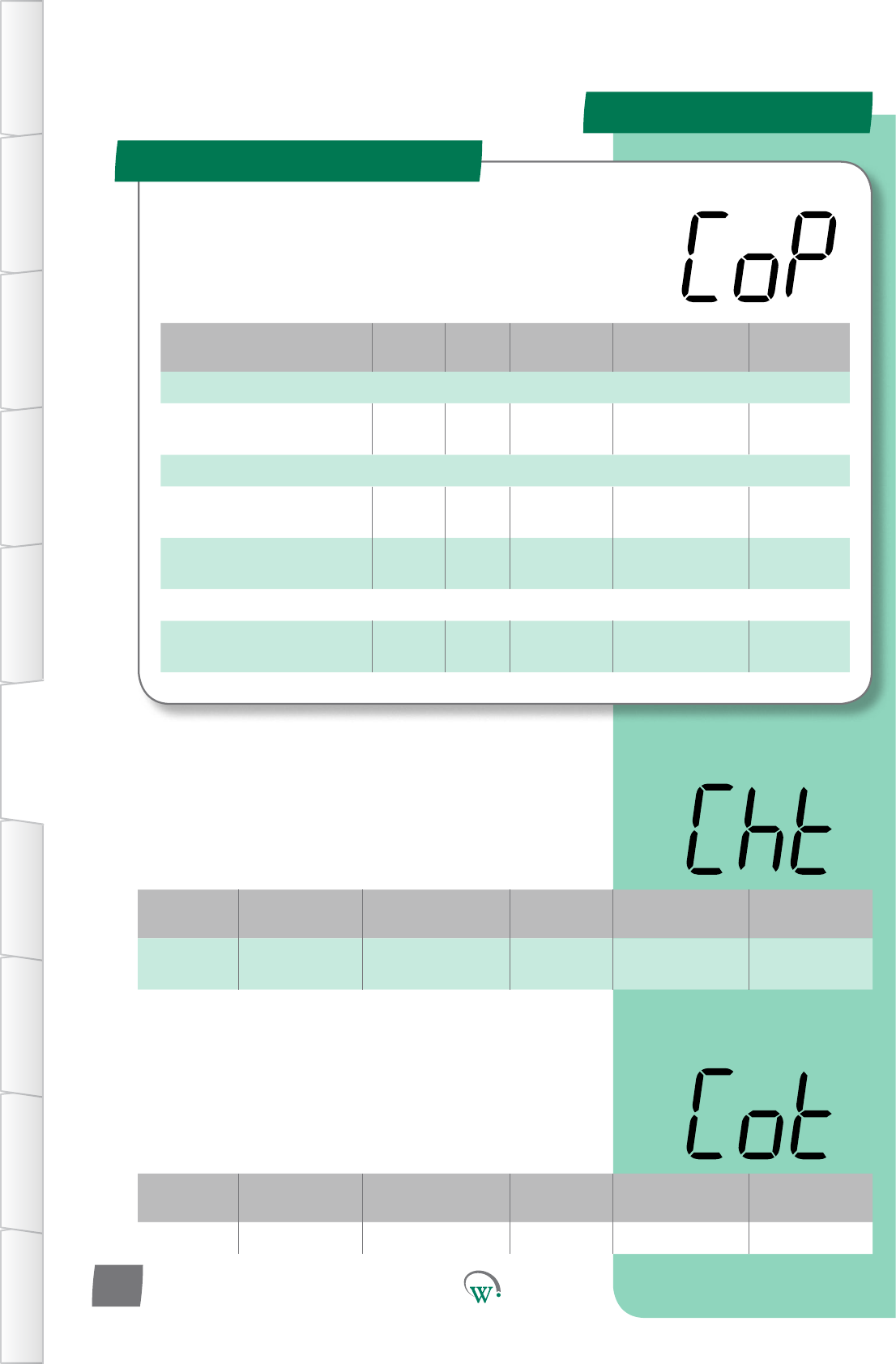
PARAMETERS
Parameter Name Digital
Display Pages Increments
&Units Range Default
TEMPERATURE
CondenserHigh
Temperature Limit Cht 68 1°C 60 °C to 150 °C
or dISabled 85 °C
TIMERS and COUNTERS
MinimumCompressorO
Time Cot 54 10 secs 10 to 1800 secs 180 secs
Compressor Maximum Starts
per Hour CSh 55 1 count dISabled dISabled
ALARMS
RefrigeraonSystemFailure
Time rSF 55 1 hour 0 to 100 hours
or dISabled 48 hours
Compressor Menu (CoP)
TABLE OF
CONTENTS
INTRODUCTION
& WARNINGS
DESCRIPTION
& INSTALLATION
FRONT PANEL
USER INTERFACE
GRAPHICAL
USER INTERFACE PARAMETERS UPGRADING
FIRMWARE
FAULTS &
ALARMS
TECHNICAL
SPECIFICATION APPENDICES
PD0006 V2.0 – 08 Jan 2016
54
Theseparametersprovideoponstocontrolandcongure
theCompressorduringdierentpartsoftherefrigeraon
cycleandtoconguretheCompressorAlarms.
Digital
Display
Funconal
Category ParameterRange Increments
&Units Default Related Menus
Cht Temperature 60 °C to 150 °C
or dISabled 1°C 85 °C Not applicable
CONDENSER HIGH TEMPERATURE LIMIT (Cht)
ThetemperaturethatturnsotheCompressorforsafetyand
proteconofthesystem.TheCompressorwillturnoonce
thistemperaturehasbeenexceedlongerthan10seconds,and
willnotturnbackonunlthetemperaturehasdropped20°C
for 3 minutes.
Digital
Display
Funconal
Category ParameterRange Increments
&Units Default Related Menus
Cot Time 10 to 1800 secs 10 secs 180 secs Not applicable
MINIMUM COMPRESSOR OFF TIME (Cot)
Theminimumamountofmethathastoelapsebetween
whentheCompressoristurnedotowhentheCompressor
isallowedtostartagain.Thismeperiodallowsthesystem
pressurestoequalizeandhelpspreventtheCompressorfrom
overheang.
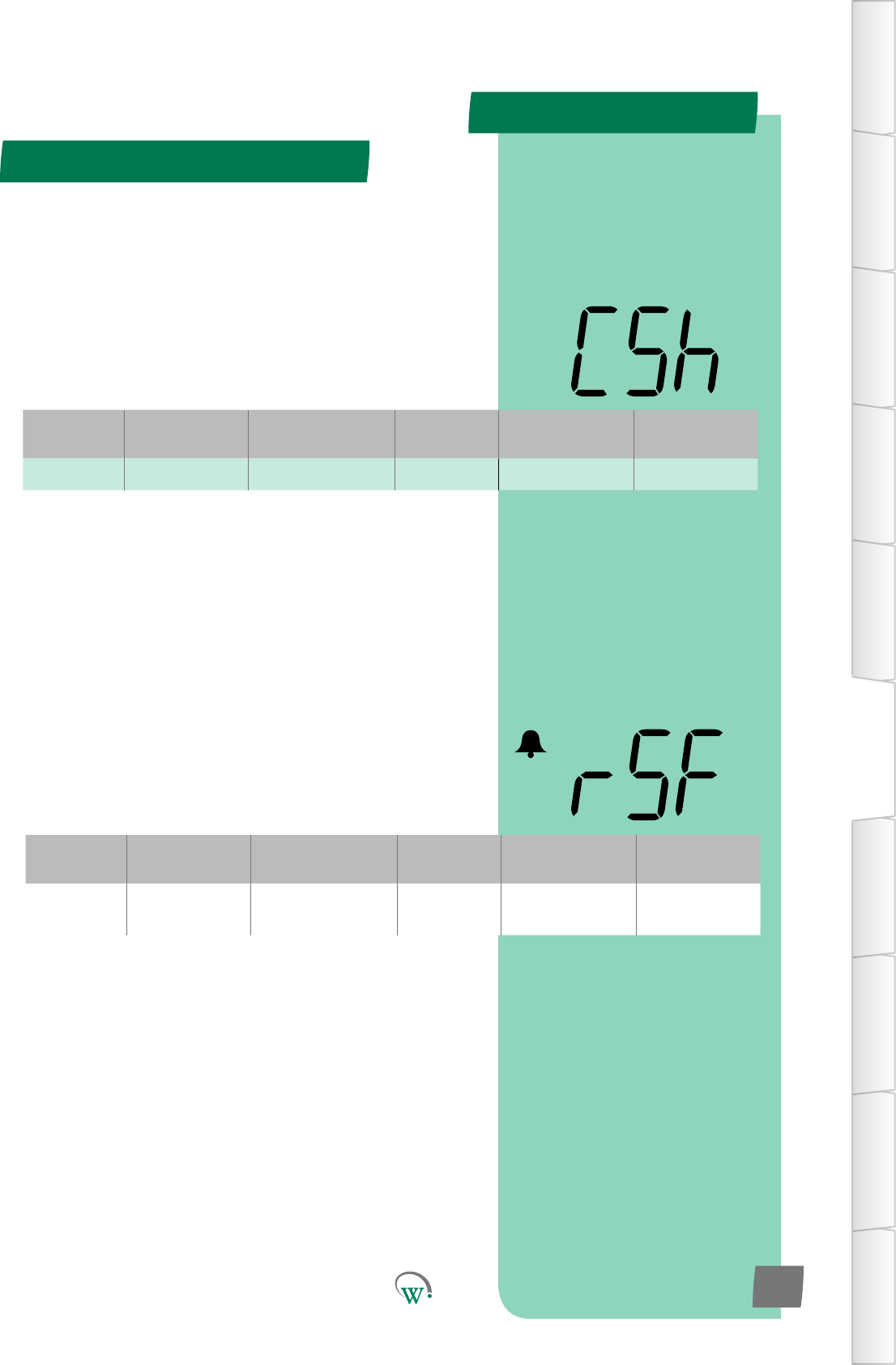
PARAMETERS
Compressor Menu (CoP) - cont
TABLE OF
CONTENTS
INTRODUCTION
& WARNINGS
DESCRIPTION
& INSTALLATION
FRONT PANEL
USER INTERFACE
GRAPHICAL
USER INTERFACE
PARAMETERS
UPGRADING
FIRMWARE
FAULTS &
ALARMS
TECHNICAL
SPECIFICATION
APPENDICES
PD0006 V2.0 – 08 Jan 2016 55
Digital
Display
Funconal
Category ParameterRange Increments
&Units Default Related Menus
rSF Alarms 0 to 100 hours
or dISabled 1 hour 48 hours Not applicable
REFRIGERATION SYSTEM FAILURE TIME (rSF)
ThemaximumpermiedmethattheCompressorcanrun
connuouslybeforethesystemisshutdownandanalarmis
triggered.
ImportantNote:Thisprotecvefunconcannotberesetby
powercyclingthecabinetonando;itcanonlyberesetbyan
authorizedServiceTechnician.
COMPRESSOR MAXIMUM STARTS PER HOUR (CSh)
The maximum number of starts a compressor can make in 1
hour,beforeithastowaitforthehourtoelapsetostartagain.
Thisistopreventoverheangwherethereisafaultinthe
system.
Note:Thisprotecvefunconcannotberesetbypowercycling
thecabinetonando
Digital
Display
Funconal
Category ParameterRange Increments
&Units Default Related Menus
CSh Counts dISabled 1 count dISabled Not applicable
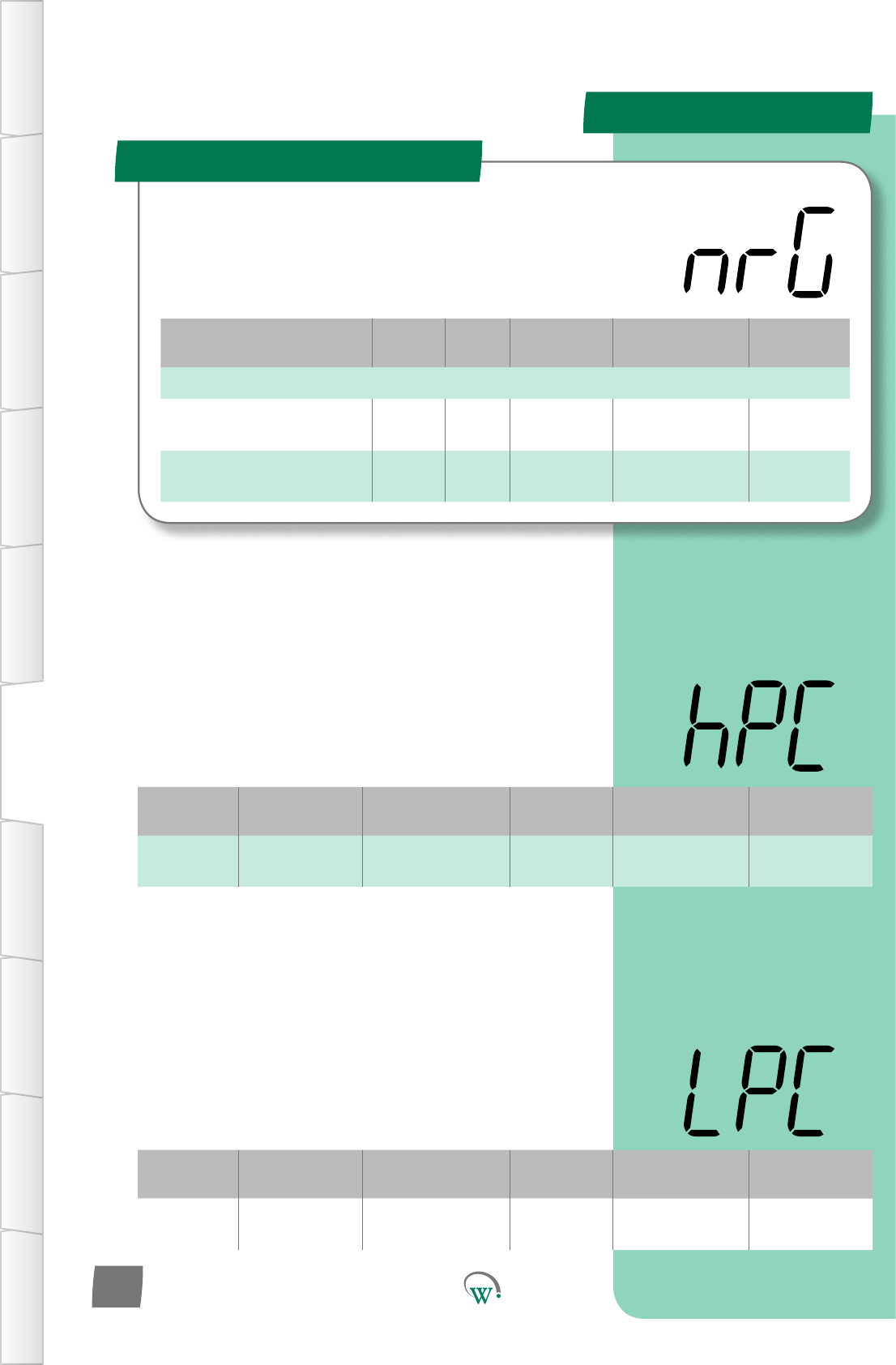
PARAMETERS
Parameter Name Digital
Display Pages Increments
&Units Range Default
SUPPLY
Maxiumum Run/Start
Voltage hPC 56 1 V 100 V to 265 V
or dISabled 254 V
Minimum Start Compressor
Voltage LPC 56 1 V 79 V to 203 V
or dISabled 90 V
Supply Menu (nrG)
TABLE OF
CONTENTS
INTRODUCTION
& WARNINGS
DESCRIPTION
& INSTALLATION
FRONT PANEL
USER INTERFACE
GRAPHICAL
USER INTERFACE PARAMETERS UPGRADING
FIRMWARE
FAULTS &
ALARMS
TECHNICAL
SPECIFICATION APPENDICES
PD0006 V2.0 – 08 Jan 2016
56
TheSupplyParametersareusedtoconguretheacceptable
limitsfortheVoltagesupplyandtoconguretheassociated
alarms.Thisisrequiredtoprotecttherefrigeraonsystem
fromelectricaldamage.
Digital
Display
Funconal
Category ParameterRange Increments
&Units Default Related Menus
hPC Supply 100 V to 265 V
or dISabled 1 V 254 V oPt, LPC
MAXIMUM RUN/START VOLTAGE (hPC)
ThemaximumVoltageatwhichtheCompressorisallowedto
start and run. AerdetecnganOverVoltagecondionthe
Compressoristurnedo.Theminimumcompressorome
must be exceeded before the compressor can turn back on.
TheseeventsareloggedintheSCS™Connect. Please also refer
to oPt for the restart sequence.
Digital
Display
Funconal
Category ParameterRange Increments
&Units Default Related Menus
LPC Supply 79 to 203 V
or dISabled 1 V 90 V hPC, oPt
MINIMUM START COMPRESSOR VOLTAGE (LPC)
TheminimumVoltageduringwhichtheCompressorisallowed
tostart.IfitisbelowthisVoltagethentheCompressor
cannotstart.IftheVoltagerisestoanacceptablelevelthen
theCompressorcanstart,butonlyaertheVoltagehasbeen
maintainedforadelayperiod.Theseeventsareloggedinthe
SCS™ Connect.
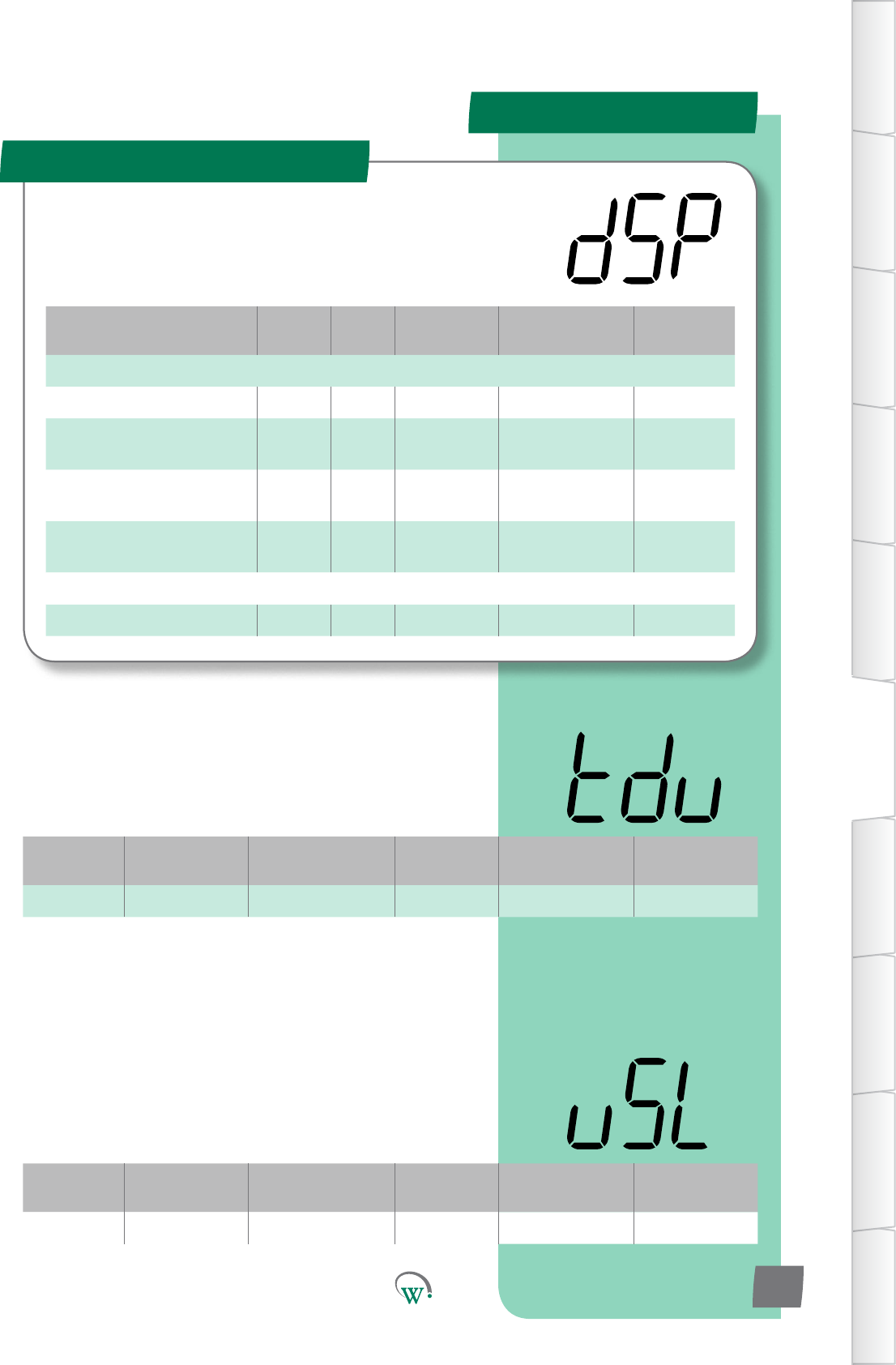
PARAMETERS
Parameter Name Digital
Display Pages Increments
&Units Range Default
DISPLAY
Temperature Display Units tdu 57 °C or °F °C or °F °C
User Set Point Keypad Lock uSL 57 text Unlocked or
Locked Locked
Maximum Displayable
Temperature dSt 58 0.1 °C -10.0 to 30.0 °C 30 °C
Minimum Displayable
Temperature dP- 58 0.1 °C -10.0 to 30.0 °C -10 °C
TIME
Temperature Display Filter tdF 58 1 secs 0 to 30 secs 5 secs
Display Menu (dSP)
TABLE OF
CONTENTS
INTRODUCTION
& WARNINGS
DESCRIPTION
& INSTALLATION
FRONT PANEL
USER INTERFACE
GRAPHICAL
USER INTERFACE
PARAMETERS
UPGRADING
FIRMWARE
FAULTS &
ALARMS
TECHNICAL
SPECIFICATION
APPENDICES
PD0006 V2.0 – 08 Jan 2016 57
Theseparameterscongurewhatisshownonthedisplay
duringdierentcontrolmodesandcondions.
Digital
Display
Funconal
Category ParameterRange Increments
&Units Default Related Menus
tdu Display °C or °F °C or °F °C SP, SSP, tS1, tS2
TEMPERATURE DISPLAY UNITS (tdu)
Selects which temperature scale is displayed; Fahrenheit or
Celsius.Thisseleconautomacallyconvertsalltemperature
displays, from all menus, into the selected scale.
C = °C
F = °F
Digital
Display
Funconal
Category ParameterRange Increments
&Units Default Related Menus
uSL Display Unlocked or Locked text Locked
USER SET POINT KEYPAD LOCK (uSL)
Locks the front keypad, to prevent the setpoint temperature
beingmodiedbyshopownersorpassersby.Setpointcansll
bechangedviatheapp,oraerapasswordhasbeenentered
into the front keypad
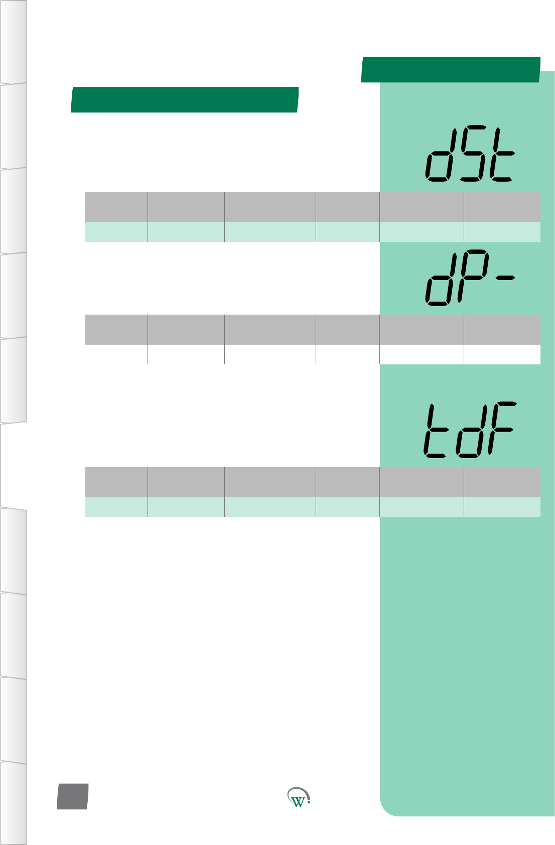
Display Menu (dSP) - cont
PARAMETERS
Display Menu (dSP) - cont
TABLE OF
CONTENTS
INTRODUCTION
& WARNINGS
DESCRIPTION
& INSTALLATION
FRONT PANEL
USER INTERFACE
GRAPHICAL
USER INTERFACE PARAMETERS UPGRADING
FIRMWARE
FAULTS &
ALARMS
TECHNICAL
SPECIFICATION APPENDICES
PD0006 V2.0 – 08 Jan 2016
58
Digital
Display
Funconal
Category ParameterRange Increments
&Units Default Related Menus
tdF Time 0 to 30 secs 1 secs 5 secs Not applicable
TEMPERATURE DISPLAY FILTER (tdF)
Themeconstantoftheresponseofthetemperaturedisplay
whenatemperaturechangeisdetected.Thispreventsthe
temperaturedisplayshowinganymisleadingtemperature
spikes.
Digital
Display
Funconal
Category ParameterRange Increments
&Units Default Related Menus
dSt Display -10.0 to 30.0 °C 0.1 °C 30 °C SPt
MAXIMUM DISPLAYABLE TEMPERATURE (dSt)
The maximum temperature that will be displayed.
Temperatures above this amount will be displayed as “-“.
Digital
Display
Funconal
Category ParameterRange Increments
&Units Default Related Menus
dP- Display -10.0 to 30.0 °C 0.1 °C -10 °C SP-
MINIMUM DISPLAYABLE TEMPERATURE (dP-)
The minimum temperature that will be displayed by the unit.
Temperatures below this amount will be displayed as “--“.
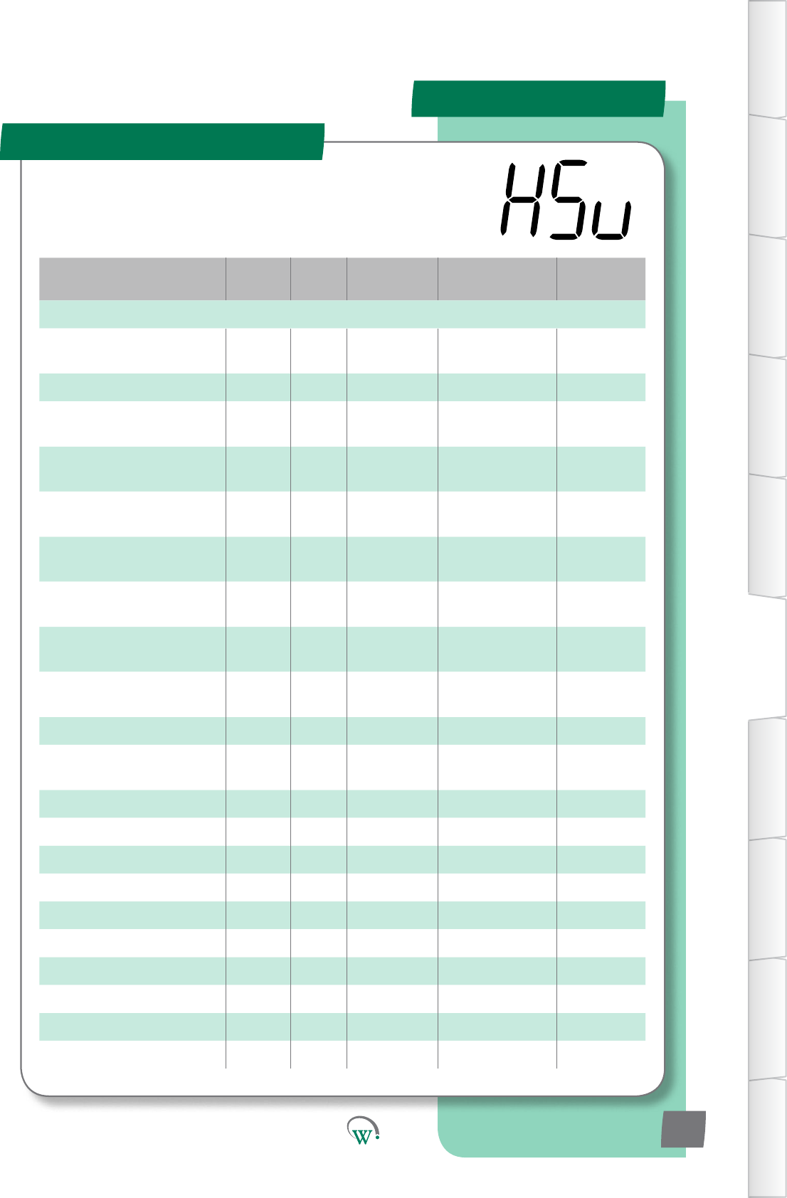
PARAMETERS
Parameter Name Digital
Display Pages Increments
&Units Range Default
INPUTS
ControlProbeCalibraon
Oset CAL 68 0.1 °C -10.0 to 10.0 °C 0.0 °C
Control Probe Response CPb 61 1 sec 5 secs 5 secs
Return Air Temperature Port rtP 62 Port ID AD1 - AD5
or N.C. AD1
Condensor Temperature Port CdP 62 Port ID AD1 - AD5
or N.C. N.C.
Ambient Temperature Port tPt 62 Port ID AD1 - AD5
or N.C. N.C.
Evap' Coil Temperature Port ELt 68 Port ID AD1 - AD5
or N.C. N.C.
Compressor Body
Temperature Port CPP 63 Port ID AD1 - AD5
or N.C. N.C.
Compressor Inlet
Temperature Port CtP 63 Port ID AD1 - AD5
or N.C. N.C.
Door Sensor Port
Conguraon dSC 63 Port ID AD1 - AD5
or N.C. AD4
Doorswitch State drS 63 integers 0 or 1 0
AcvitySensorPort
Conguraon SCF 64 Port ID AD1 - AD5
or N.C. N.C.
AcvitySensorState SrS 64 integers 0 or 1 0
NTC 1 Beta value n1b 64 integers 3400-4000 3960
NTC 1 Resistance n1r 65 1 ohm 1000-15000 10,000
NTC 2 Beta value n2b 65 integers 3400-4000 3960
NTC 2 Resistance n2r 65 1 ohm 1000-15000 10,000
AD1 NTC Type Ad1 65 integers 1-2 1
AD2 NTC Type Ad2 65 integers 1-2 1
AD3 NTC Type Ad3 66 integers 1-2 1
AD4 NTC Type Ad4 66 integers 1-2 1
AD5 NTC Type Ad5 66 integers 1-2 1
Hardware Set Up Menu (HSu)
TABLE OF
CONTENTS
INTRODUCTION
& WARNINGS
DESCRIPTION
& INSTALLATION
FRONT PANEL
USER INTERFACE
GRAPHICAL
USER INTERFACE
PARAMETERS
UPGRADING
FIRMWARE
FAULTS &
ALARMS
TECHNICAL
SPECIFICATION
APPENDICES
PD0006 V2.0 – 08 Jan 2016 59
TheHardwareSetUpParametersdenehowtheperipheral
RefrigeraonSystemcomponentsareconnectedtotheSCS
Connect for input and output control.
PARAMETERS
Parameter Name Digital
Display Pages Increments
&Units Range Default
OUTPUTS
Output Interval Time oPt 66 1 second 0 secs 0 secs
Compressor Port
Conguraon CPC 67 Port ID R, C
or N.C. C
Compressor State CPS 67 integers 0 or 1 0
Evaporator Fan Port
Conguraon EFC 67 Port ID S1,S2,S1&S2,
R or N.C. S1
Evaporator Fan Control Type ECt 67 text on/oorVar on/o
EvaporatorFanDIrecon EFd 68 Dir CW or CCW CCW
Condensor Fan Port
Conguraon CdC 68 Port ID S1, S2
or N.C. N.C.
Condensor Fan Control Type CCt 68 text on/oorVar on/o
CondensorFanDIrecon CFd 68 Dir CW or CCW CCW
DefrostPortConguraon dFC 69 Port ID R, C
or N.C. N.C.
Defrost State dFS 69 integers 0 or 1 0
LighngPortConguraon-
Channel A LCA 69 Port ID
LE1,LE2,LE3, S1,
S2, R, C
or N.C.
R
LighngPortConguraon-
Channel B LCb 70 Port ID
LE1,LE2,LE3, S1,
S2, R, C
or N.C.
N.C.
LighngPortConguraon-
Channel C LCC 70 Port ID
LE1,LE2,LE3, S1,
S2, R, C
or N.C.
N.C.
LighngStateChannelA LEA 70 integers 0 or 1 0
LighngStateChannelB LEb 71 integers 0 or 1 0
LighngStateChannelC LEC 71 integers 0 or 1 0
Hardware Set Up (HSu) - cont
TABLE OF
CONTENTS
INTRODUCTION
& WARNINGS
DESCRIPTION
& INSTALLATION
FRONT PANEL
USER INTERFACE
GRAPHICAL
USER INTERFACE PARAMETERS UPGRADING
FIRMWARE
FAULTS &
ALARMS
TECHNICAL
SPECIFICATION APPENDICES
PD0006 V2.0 – 08 Jan 2016
60
PARAMETERS
Digital
Display
Funconal
Category ParameterRange Increments
&Units Default Related Menus
CAL Hardware
Set Up -10.0 to 10.0 °C 0.1 °C 0.0 °C HSu
Digital
Display
Funconal
Category ParameterRange Increments
&Units Default Related Menus
CPb Hardware
Set Up 5 secs 1 sec 5 secs HSu
Hardware Set Up (HSu) - cont
LE2 AD5
AD4 AD3
R
C
S2
S1
LE3
LE1
DSO AD2 AD1
Port Idencaon
Digital
Switched
Output
AD5
TABLE OF
CONTENTS
INTRODUCTION
& WARNINGS
DESCRIPTION
& INSTALLATION
FRONT PANEL
USER INTERFACE
GRAPHICAL
USER INTERFACE
PARAMETERS
UPGRADING
FIRMWARE
FAULTS &
ALARMS
TECHNICAL
SPECIFICATION
APPENDICES
PD0006 V2.0 – 08 Jan 2016 61
* CONTROL PROBE RESPONSE (CPb)
DampenstheresponsemeoftheControlProbetominimize
theeectofmomentarytemperaturespikeswhichmay
otherwisetriggerunnecessarysystemcycles.Arollingaverage
iscalculatedoverthechosenamountofme.
* Not yet adjustable
CONTROL PROBE CALIBRATION OFFSET (CAL)
TheosetamountappliedtotheControlProbeoutputto
compensate between the measured value and the actual
product temperature inside the cabinet. This parameter is not
congurableintheeld.
PARAMETERS
Digital
Display
Funconal
Category ParameterRange Increments
&Units Default Related Menus
CdP Hardware
Set Up
AD1 - AD5
or N.C. Port ID N.C. Cht
Digital
Display
Funconal
Category ParameterRange Increments
&Units Default Related Menus
tPt Hardware
Set Up
AD1 - AD5
or N.C. Port ID N.C. SP, SSP, tS1, tS2,
dEF
Digital
Display
Funconal
Category ParameterRange Increments
&Units Default Related Menus
ELt Hardware
Set Up
AD1 - AD5
or N.C. Port ID N.C. EFC
Digital
Display
Funconal
Category ParameterRange Increments
&Units Default Related Menus
rtP Hardware
Set Up
AD1 - AD5
or N.C. Port ID AD1 CAL, SP, SSP, tS1,
tS2
Hardware Set Up (HSu) - cont
TABLE OF
CONTENTS
INTRODUCTION
& WARNINGS
DESCRIPTION
& INSTALLATION
FRONT PANEL
USER INTERFACE
GRAPHICAL
USER INTERFACE PARAMETERS UPGRADING
FIRMWARE
FAULTS &
ALARMS
TECHNICAL
SPECIFICATION APPENDICES
PD0006 V2.0 – 08 Jan 2016
62
EVAPORATOR COIL TEMPERATURE PORT (ELt)
SelectstheEvaporatorCoilTemperatureProbeconneconport:
N.C. = Not Connected
AD1–AD5=AnalogorDigitali/p
CONDENSER TEMPERATURE PORT (CdP)
SelectstheCondenserTemperatureProbeconneconport.
This may also be called the Gas Cooler Probe in CO2 systems:
N.C. = Not Connected
AD1–AD5=AnalogorDigitali/p
AMBIENT TEMPERATURE PORT (tPt)
SelectstheAmbientTemperatureProbeconneconport.
N.C. = Not Connected
AD1–AD5=AnalogorDigitali/p
RETURN AIR TEMPERATURE PORT (rtP)
SelectstheReturnAirTemperatureProbeconneconport:
N.C. = Not Connected
AD1–AD5=AnalogorDigitali/p
PARAMETERS
Digital
Display
Funconal
Category ParameterRange Increments
&Units Default Related Menus
CPP Hardware
Set Up
AD1 - AD5
or N.C. Port ID N.C. CPS, CtP
Digital
Display
Funconal
Category ParameterRange Increments
&Units Default Related Menus
CtP Hardware
Set Up
AD1 - AD5
or N.C. Port ID N.C. CPP, CPS
Digital
Display
Funconal
Category ParameterRange Increments
&Units Default Related Menus
dSC Hardware
Set Up
AD1 - AD5
or N.C. Port ID AD4 drS
Digital
Display
Funconal
Category ParameterRange Increments
&Units Default Related Menus
drS Hardware
Set Up 0 or 1 integers 0 dSC
TABLE OF
CONTENTS
INTRODUCTION
& WARNINGS
DESCRIPTION
& INSTALLATION
FRONT PANEL
USER INTERFACE
GRAPHICAL
USER INTERFACE
PARAMETERS
UPGRADING
FIRMWARE
FAULTS &
ALARMS
TECHNICAL
SPECIFICATION
APPENDICES
PD0006 V2.0 – 08 Jan 2016 63
Hardware Set Up (HSu) - cont
COMPRESSOR BODY TEMPERATURE PORT (CPP)
SelectstheCompressorBodyTemperatureProbeconnecon
port.
N.C. = Not Connected
AD1–AD5=AnalogorDigitali/p
COMPRESSOR INLET TEMPERATURE PORT (CtP)
SelectstheCompressorInletTemperatureProbeconnecon
port:
N.C. = Not Connected
AD1–AD5=AnalogorDigitali/p
DOOR SENSOR PORT CONFIGURATION (dSC)
SelectstheDoorSensorconneconport.Pleasealsoreferto
‘Door Switch State’ (drS).
N.C. = Not Connected
AD1–AD5=AnalogorDigitali/p
DOOR SWITCH STATE (drS)
Selects the sensor state when the cabinet door is open. Please
alsoreferto‘DoorSensorPortConguraon’(dSC).
0=Thecabinetdoorisopenwhenthei/phashighimpedance.
1 = The cabinet door is open when the i/p has low impedance.
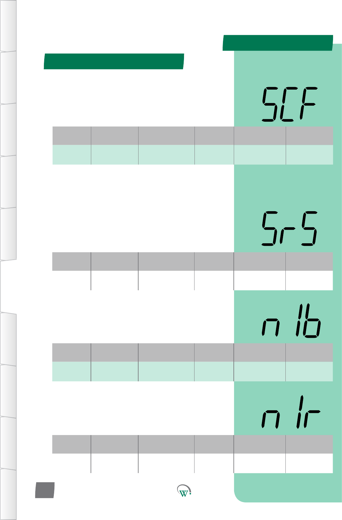
PARAMETERS
Digital
Display
Funconal
Category ParameterRange Increments
&Units Default Related Menus
SCF Hardware
Set Up
AD1 - AD5
or N.C. Port ID N.C. SrS
Digital
Display
Funconal
Category ParameterRange Increments
&Units Default Related Menus
SrS Hardware
Set Up 0 or 1 integers 0 SCF
Digital
Display
Funconal
Category ParameterRange Increments
&Units Default Related Menus
n1b Hardware
Set Up 3400-4000 integers 3960 n1r
Digital
Display
Funconal
Category ParameterRange Increments
&Units Default Related Menus
n1r Hardware
Set Up 1000-15000 1 ohm 10000 n1b
Hardware Set Up (HSu) - cont
TABLE OF
CONTENTS
INTRODUCTION
& WARNINGS
DESCRIPTION
& INSTALLATION
FRONT PANEL
USER INTERFACE
GRAPHICAL
USER INTERFACE PARAMETERS UPGRADING
FIRMWARE
FAULTS &
ALARMS
TECHNICAL
SPECIFICATION APPENDICES
PD0006 V2.0 – 08 Jan 2016
64
ACTIVITY SENSOR PORT CONFIGURATION (SCF)
SelectstheAcvitySensorconnectorport.Pleasealsoreferto
‘AcvitySensorState’(SrS).
N.C. = Not Connected
AD1–AD5=AnalogorDigitali/p
ACTIVITY SENSOR STATE (SrS)
SelectswhichstatetheRelayisinwhentheAcvitySensor
detectsacvity.Pleasealsoreferto‘AcvitySensorPort
Conguraon’(SCF).
0=TheAcvitySensordetectsacvitywhenthei/phashigh
impedance.
1=TheAcvitySensordetectsacvitywhenthei/phaslow
impedance.
NTC 1 BETA VALUE (n1b)
ThebetavalueuseforNTCtype1.TwodierentNTCtypescan
be used simultaneously.
NTC 1 RESISTANCE (n1r)
The resistance at 25°CforNTCtype1.TwodierentNTCtypes
can be used simultaneously.
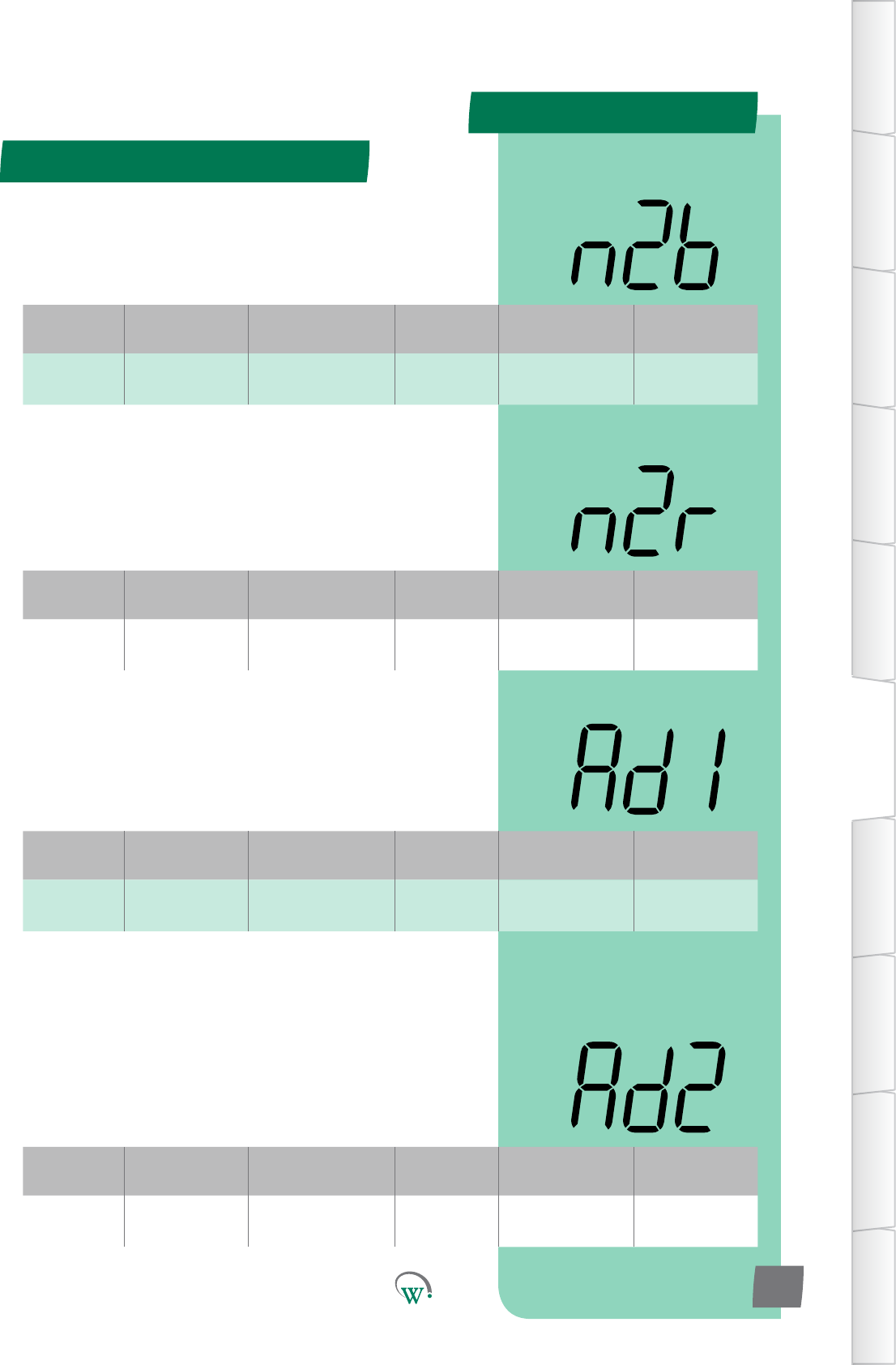
PARAMETERS
Digital
Display
Funconal
Category ParameterRange Increments
&Units Default Related Menus
n2b Hardware
Set Up 3400-4000 integers 3960 n2r
Digital
Display
Funconal
Category ParameterRange Increments
&Units Default Related Menus
n2r Hardware
Set Up 100-15000 1 ohm 10000 n2b
Digital
Display
Funconal
Category ParameterRange Increments
&Units Default Related Menus
Ad1 Hardware
Set Up 1-2 integers 1n1b,n1r,
n2b,n2r
Digital
Display
Funconal
Category ParameterRange Increments
&Units Default Related Menus
Ad2 Hardware
Set Up 1-2 integers 1n1b,n1r,
n2b,n2r
Hardware Set Up (HSu) - cont
TABLE OF
CONTENTS
INTRODUCTION
& WARNINGS
DESCRIPTION
& INSTALLATION
FRONT PANEL
USER INTERFACE
GRAPHICAL
USER INTERFACE
PARAMETERS
UPGRADING
FIRMWARE
FAULTS &
ALARMS
TECHNICAL
SPECIFICATION
APPENDICES
PD0006 V2.0 – 08 Jan 2016 65
NTC 2 BETA VALUE (n2b)
ThebetavalueuseforNTCtype2.TwodierentNTCtypescan
be used simultaneously.
NTC 2 RESISTANCE (n2r)
The resistance at 25°CforNTCtype2.TwodierentNTCtypes
can be used simultaneously.
AD1 NTC TYPE (Ad1)
Determines which NTC type is connected to AD1. The NTC type
isdenedbybetavalueandresistance.
AD1 NTC TYPE (Ad2)
Determines which NTC type is connected to AD2. The NTC type
isdenedbybetavalueandresistance.
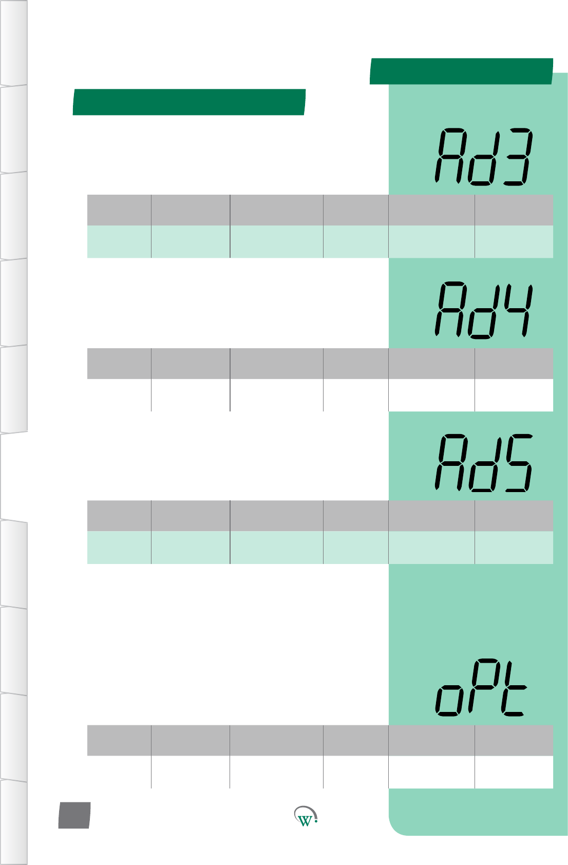
PARAMETERS
Digital
Display
Funconal
Category ParameterRange Increments
&Units Default Related Menus
oPt Hardware
Set Up 0 secs 1 second 0 secs hPC
Digital
Display
Funconal
Category ParameterRange Increments
&Units Default Related Menus
Ad3 Hardware
Set Up 1-2 integers 1n1b,n1r,
n2b,n2r
Digital
Display
Funconal
Category ParameterRange Increments
&Units Default Related Menus
Ad4 Hardware
Set Up 1-2 integers 1n1b,n1r,
n2b,n2r
Digital
Display
Funconal
Category ParameterRange Increments
&Units Default Related Menus
Ad5 Hardware
Set Up 1-2 integers 1n1b,n1r,
n2b,n2r
Hardware Set Up (HSu) - cont
TABLE OF
CONTENTS
INTRODUCTION
& WARNINGS
DESCRIPTION
& INSTALLATION
FRONT PANEL
USER INTERFACE
GRAPHICAL
USER INTERFACE PARAMETERS UPGRADING
FIRMWARE
FAULTS &
ALARMS
TECHNICAL
SPECIFICATION APPENDICES
PD0006 V2.0 – 08 Jan 2016
66
* OUPUT INTERVAL TIME (oPt)
Themedelaybetweenanytwodevicesturningontoprevent
overloading.Thestartupsequenceforconnecteddevicesisas
follows:
1.Lights
2. Evaporator Fan
3. Compressor
4. Condenser Fan
* Not yet adjustable
AD1 NTC TYPE (Ad3)
Determines which NTC type is connected to AD3. The NTC type
isdenedbybetavalueandresistance.
AD1 NTC TYPE (Ad4)
Determines which NTC type is connected to AD4. The NTC type
isdenedbybetavalueandresistance.
AD1 NTC TYPE (Ad5)
Determines which NTC type is connected to AD5. The NTC type
isdenedbybetavalueandresistance.
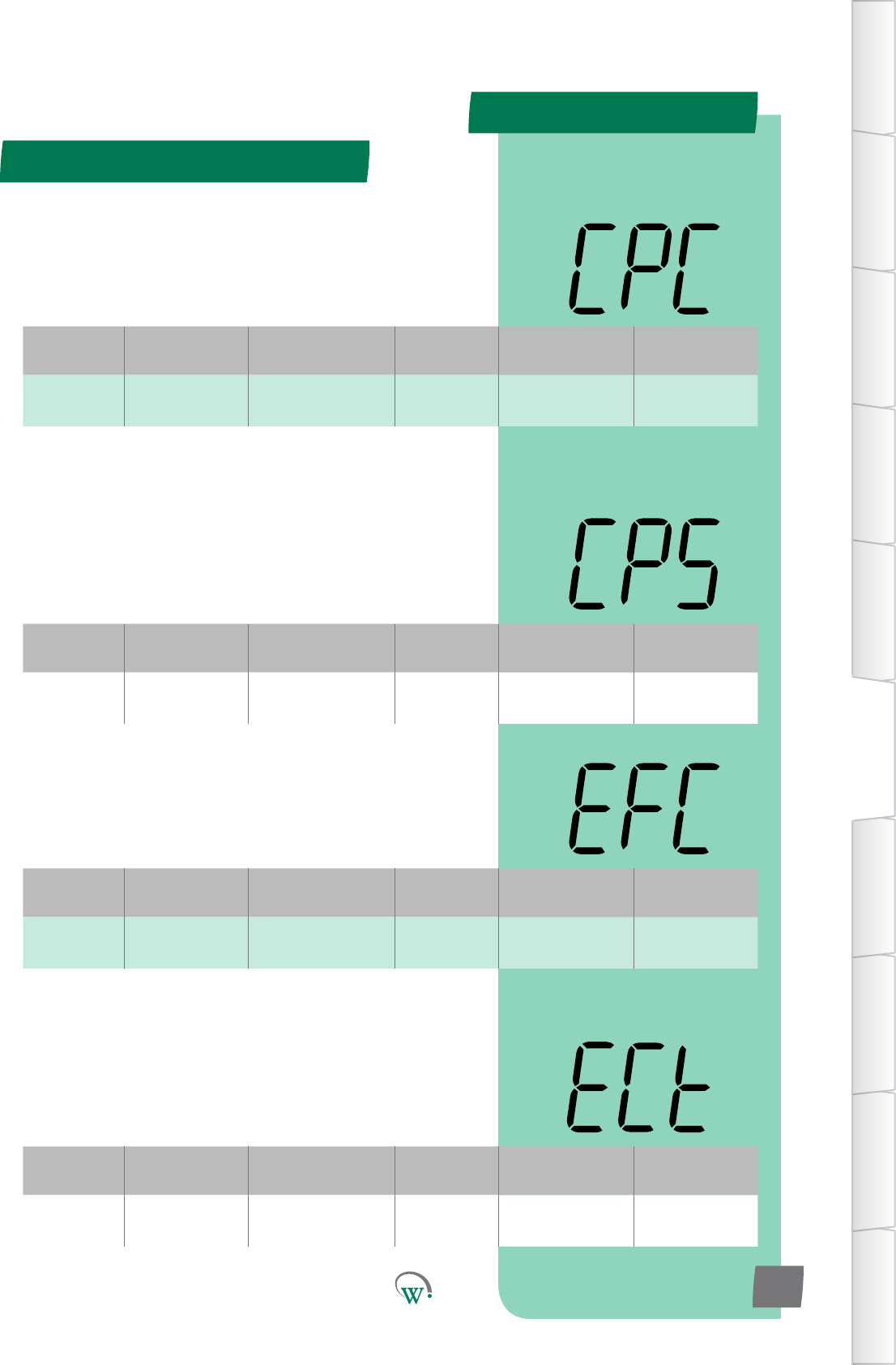
PARAMETERS
Digital
Display
Funconal
Category ParameterRange Increments
&Units Default Related Menus
CPC Hardware
Set Up
R, C
or N.C. Port ID C hPC, LPC
Digital
Display
Funconal
Category ParameterRange Increments
&Units Default Related Menus
CPS Hardware
Set Up 0 or 1 integers 0 CPP, CtP
Digital
Display
Funconal
Category ParameterRange Increments
&Units Default Related Menus
EFC Hardware
Set Up
S1,S2,S1&S2
R or N.C. Port ID S1 ECt
Digital
Display
Funconal
Category ParameterRange Increments
&Units Default Related Menus
ECt Hardware
Set Up on/oorvar text on/o
Hardware Set Up (HSu) - cont
TABLE OF
CONTENTS
INTRODUCTION
& WARNINGS
DESCRIPTION
& INSTALLATION
FRONT PANEL
USER INTERFACE
GRAPHICAL
USER INTERFACE
PARAMETERS
UPGRADING
FIRMWARE
FAULTS &
ALARMS
TECHNICAL
SPECIFICATION
APPENDICES
PD0006 V2.0 – 08 Jan 2016 67
COMPRESSOR PORT CONFIGURATION (CPC)
SelectstheCompressorconneconport:
N.C. = Not Connected
R = 5A Relay o/p
C = 12A Relay o/p
COMPRESSOR STATE (CPS)
Selects the Relay state when the Compressor is on. This
funconisonlyusedwhenanExternalRelayisedtothe
Compressor.
0 = Normally open (Relay contact open when Compressor is
o).Default.
1 = Normally closed (Relay contact closed when Compressor is
o).
EVAPORATOR FAN CONTROL TYPE (ECt)
Selects whether the Evaporator Fan Port operates as an ON/
OFF switch or as a variable speed fan control output.
0 = Normal Switch
1 = Variable Speed Fan Control
EVAPORATOR FAN PORT CONFIGURATION (EFC)
SelectstheEvaporatorFanconneconport.
N.C. = Not Connected
S1&S2=0.4/0.6ASolidStateRelayo/p
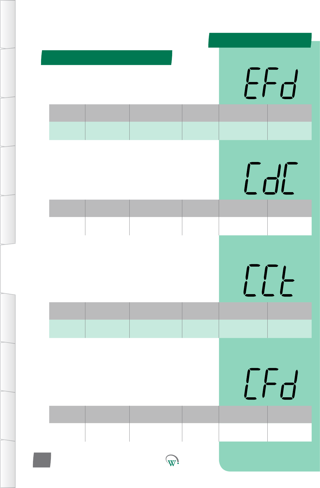
PARAMETERS
Digital
Display
Funconal
Category ParameterRange Increments
&Units Default Related Menus
EFd Hardware
Set Up CW or CCW text CCW
Digital
Display
Funconal
Category ParameterRange Increments
&Units Default Related Menus
CdC Hardware
Set Up
S1, S2
or N.C. Port ID N.C. Cht
Digital
Display
Funconal
Category ParameterRange Increments
&Units Default Related Menus
CCt Hardware
Set Up on/oorvar text on/o
Digital
Display
Funconal
Category ParameterRange Increments
&Units Default Related Menus
CFd Hardware
Set Up CW or CCW text CCW
Hardware Set Up (HSu) - cont
TABLE OF
CONTENTS
INTRODUCTION
& WARNINGS
DESCRIPTION
& INSTALLATION
FRONT PANEL
USER INTERFACE
GRAPHICAL
USER INTERFACE PARAMETERS UPGRADING
FIRMWARE
FAULTS &
ALARMS
TECHNICAL
SPECIFICATION APPENDICES
PD0006 V2.0 – 08 Jan 2016
68
CONDENSER FAN PORT CONFIGURATION (CdC)
SelectstheCondenserFanconneconport:
N.C. = Not Connected
S1&S2=0.4/0.6ASolidStateRelayo/p
CONDENSER FAN CONTROL TYPE (CCt)
Selects whether the Condenser Fan Port operates as an ON/OFF
switch or as a variable speed fan control output.
0 = Normal Switch
1 = Variable Speed Fan Control
EVAPORATOR FAN DIRECTION (EFd)
Selectsthedireconoftheevaporatorfanrotaon
CONDENSOR FAN DIRECTION (CFd)
Selectsthedireconofthecondensorfanrotaon
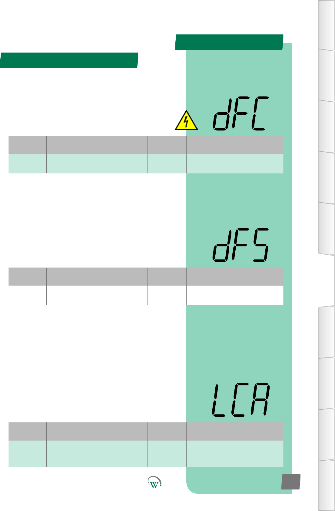
PARAMETERS
Digital
Display
Funconal
Category ParameterRange Increments
&Units Default Related Menus
dFC Hardware
Set Up
R, C
or N.C. Port ID N.C. dFS, dtP
Digital
Display
Funconal
Category ParameterRange Increments
&Units Default Related Menus
dFS Hardware
Set Up 0 or 1 integers 0dFC
Digital
Display
Funconal
Category ParameterRange Increments
&Units Default Related Menus
LCA Hardware
Set Up
LE1,LE2,LE3, S1, S2,
R, C
or N.C.
Port ID R LEA, LEb, LEC
Hardware Set Up (HSu) - cont
TABLE OF
CONTENTS
INTRODUCTION
& WARNINGS
DESCRIPTION
& INSTALLATION
FRONT PANEL
USER INTERFACE
GRAPHICAL
USER INTERFACE
PARAMETERS
UPGRADING
FIRMWARE
FAULTS &
ALARMS
TECHNICAL
SPECIFICATION
APPENDICES
PD0006 V2.0 – 08 Jan 2016 69
DEFROST PORT CONFIGURATION (dFC)
SelectstheDefrostCoilconneconport.Thisfunconisonly
used with a Heated Defrost Cycle. Please also refer to ‘Defrost
State’ (dFS).
N.C. = Not Connected
R = 5A Relay o/p
C = 12A Relay o/p
LIGHTING PORT CONFIGURATION–CHANNELA (LCA)
SelectsthelighngconneconPort.Pleasealsoreferto
LighngStateChannelA(LEA).
N.C. = Not Connected
R = 5A Relay o/p
C = 12A Relay o/p
S1, S2 = 0.4/0.6A Solid State Relay o/p
LE1–LE3=Switched24Vo/p
DEFROST STATE (dFS)
SelectstheRelaystatewhentheDefrostCycleiso.Please
alsoreferto‘DefrostPortConguraon’(dFC).
0 = Normally open (Relay contact open when Defrost Cycle not
running).Default.
1 = Normally closed (Relay contact closed when Defrost Cycle
notrunning).
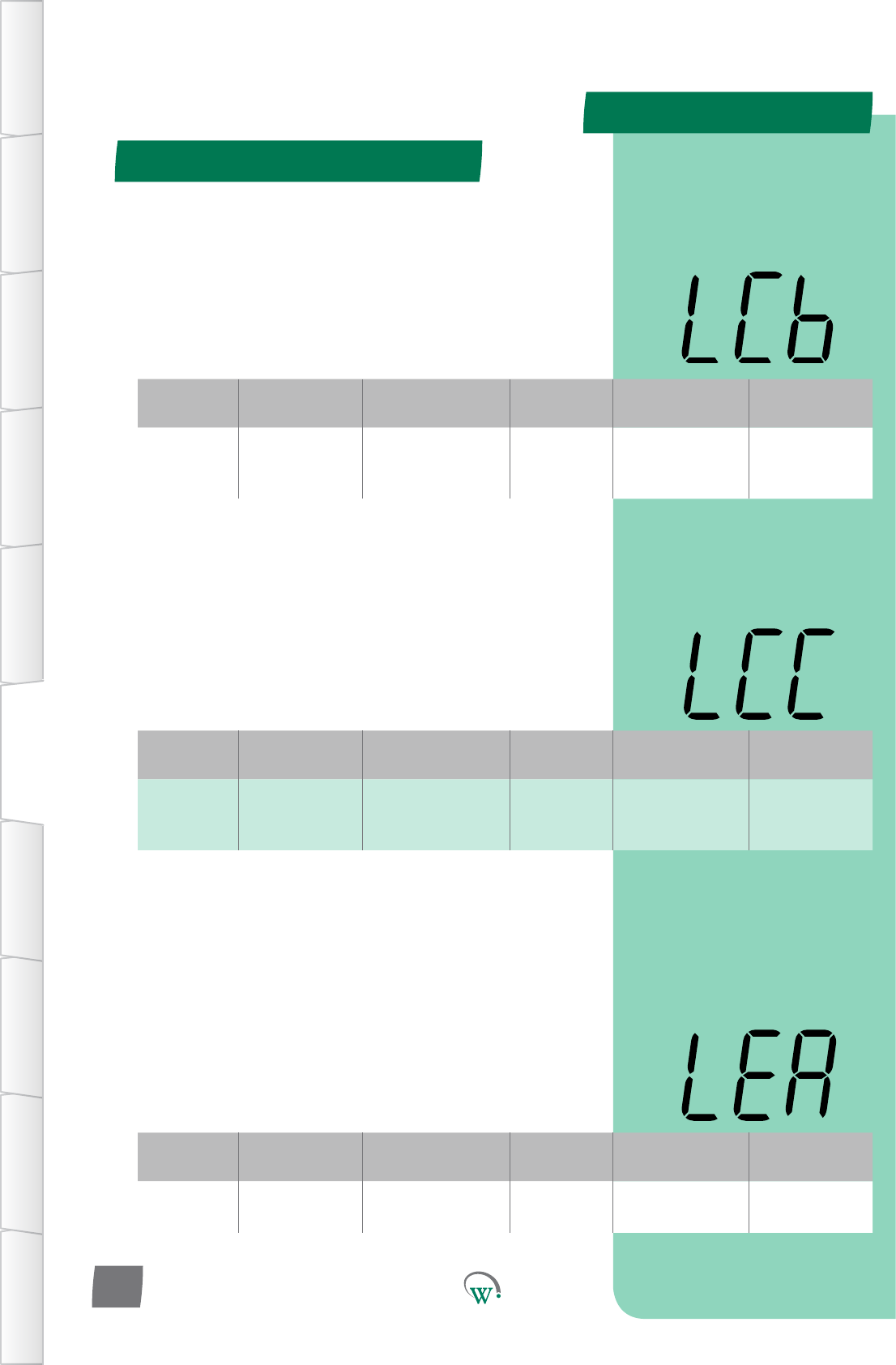
PARAMETERS
Digital
Display
Funconal
Category ParameterRange Increments
&Units Default Related Menus
LCb Hardware
Set Up
LE1,LE2,LE3, S1, S2,
R, C
or N.C.
Port ID N.C. LEA, LEb, LEC
Digital
Display
Funconal
Category ParameterRange Increments
&Units Default Related Menus
LCC Hardware
Set Up
LE1,LE2,LE3, S1, S2,
R, C
or N.C.
Port ID N.C. LEA, LEb, LEC
Digital
Display
Funconal
Category ParameterRange Increments
&Units Default Related Menus
LEA Hardware
Set Up 0 or 1 integers 0 LCA, LCb, LCC
Hardware Set Up (HSu) - cont
TABLE OF
CONTENTS
INTRODUCTION
& WARNINGS
DESCRIPTION
& INSTALLATION
FRONT PANEL
USER INTERFACE
GRAPHICAL
USER INTERFACE PARAMETERS UPGRADING
FIRMWARE
FAULTS &
ALARMS
TECHNICAL
SPECIFICATION APPENDICES
PD0006 V2.0 – 08 Jan 2016
70
LIGHTING PORT CONFIGURATION–CHANNELB (LCb)
SelectsthelighngconneconPort.Pleasealsoreferto
LighngStateChannelB(LEb).
N.C. = Not Connected
R = 5A Relay o/p
C = 12A Relay o/p
S1, S2 = 0.4/0.6A Solid State Relay o/p
LE1–LE3=Switched24Vo/p
LIGHTING PORT CONFIGURATION–CHANNELC (LCC)
SelectsthelighngconneconPort.Pleasealsoreferto
LighngStateChannelC(LEC).
N.C. = Not Connected
R = 5A Relay o/p
C = 12A Relay o/p
S1, S2 = 0.4/0.6A Solid State Relay o/p
LE1–LE3=Switched24Vo/p
LIGHTING STATE CHANNEL A (LEA)
Selectsthestatewhenthelighngiso.Pleasealsoreferto
theLighngPortConguraon–ChannelA(LCA).
0=NormallyOpen(Relaycontactopenwhenlightsareo)
(Switched24Vopenwhenlightsareo)
1=NormallyClosed(Relaycontactclosedwhenlightsareo)
(Switched24Vclosedwhenlightsareo)
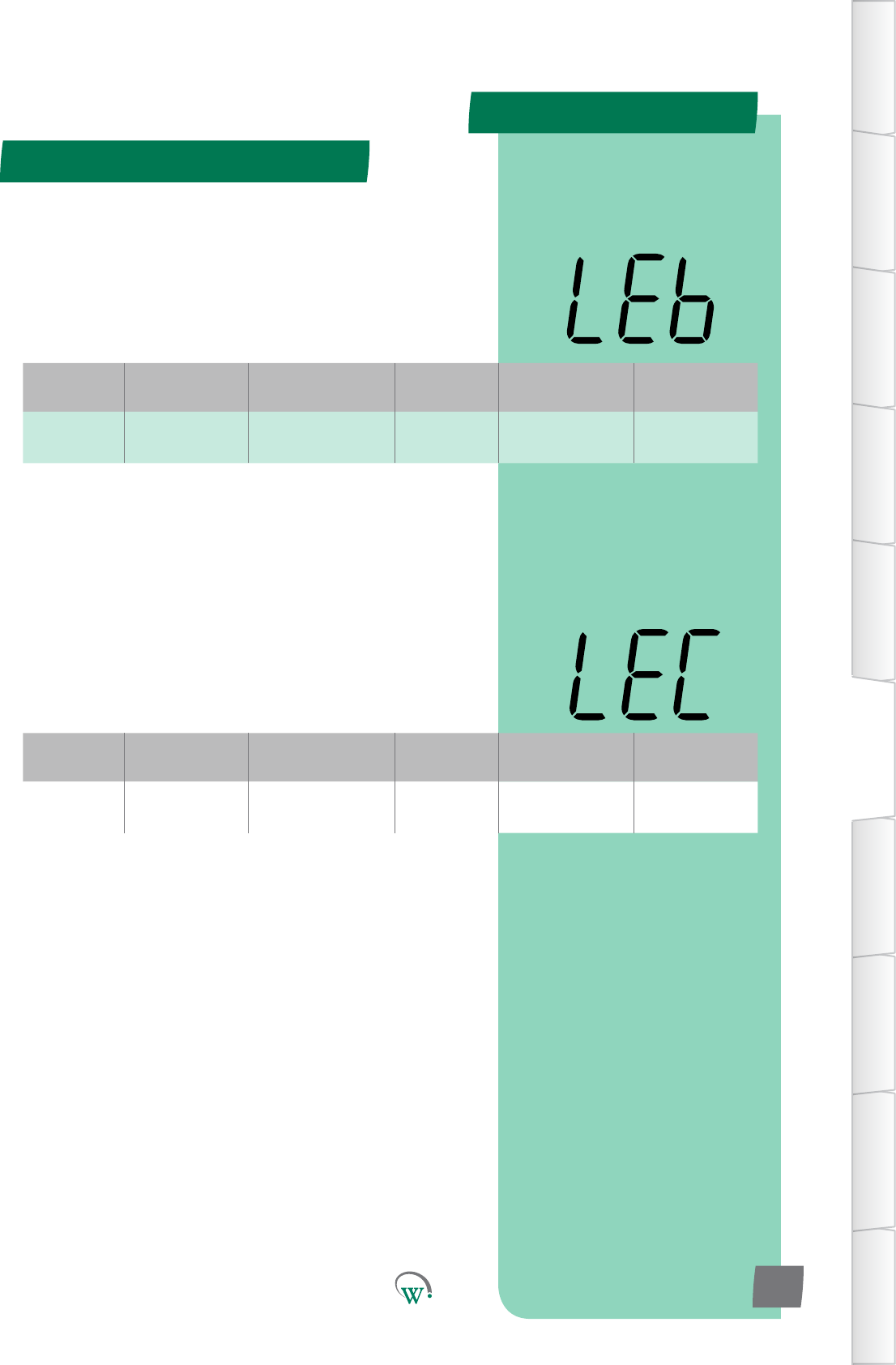
PARAMETERS
Digital
Display
Funconal
Category ParameterRange Increments
&Units Default Related Menus
LEb Hardware
Set Up 0 or 1 integers 0 LCA, LCb, LCC
Digital
Display
Funconal
Category ParameterRange Increments
&Units Default Related Menus
LEC Hardware
Set Up 0 or 1 integers 0 LCA, LCb, LCC
Hardware Set Up (HSu) - cont
TABLE OF
CONTENTS
INTRODUCTION
& WARNINGS
DESCRIPTION
& INSTALLATION
FRONT PANEL
USER INTERFACE
GRAPHICAL
USER INTERFACE
PARAMETERS
UPGRADING
FIRMWARE
FAULTS &
ALARMS
TECHNICAL
SPECIFICATION
APPENDICES
PD0006 V2.0 – 08 Jan 2016 71
LIGHTING STATE CHANNEL B (LEb)
Selectsthestatewhenthelighngiso.Pleasealsoreferto
theLighngPortConguraon–ChannelB(LCb).
0=NormallyOpen(Relaycontactopenwhenlightsareo)
(Switched24Vopenwhenlightsareo)
1=NormallyClosed(Relaycontactclosedwhenlightsareo)
(Switched24Vclosedwhenlightsareo)
LIGHTING STATE CHANNEL C (LEC)
Selectsthestatewhenthelighngiso.Pleasealsoreferto
theLighngPortConguraon–ChannelC(LCC).
0=NormallyOpen(Relaycontactopenwhenlightsareo)
(Switched24Vopenwhenlightsareo)
1=NormallyClosed(Relaycontactclosedwhenlightsareo)
(Switched24Vclosedwhenlightsareo)
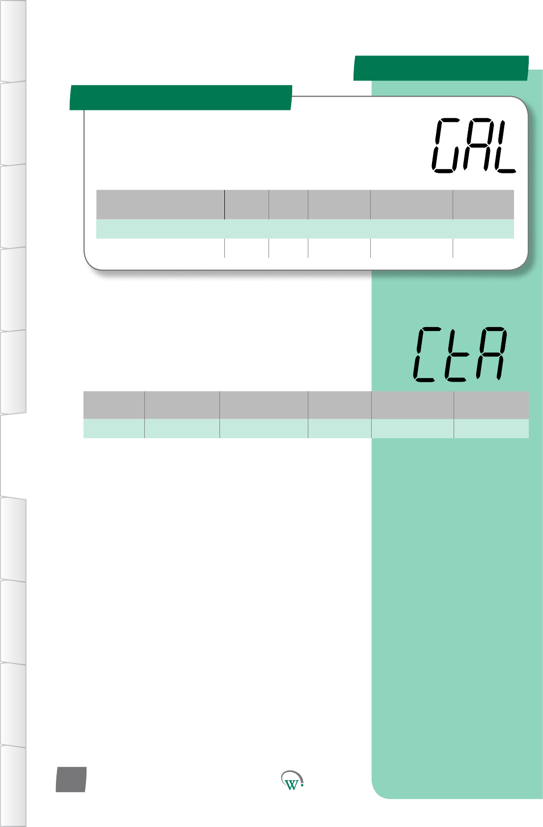
PleaseP
PARAMETERS
Parameter Name Digital
Display Pages Increments
&Units Range Default
ALARMS
Clear Terminal Alarm CtA 72 n/a yES or no no
Digital
Display
Funconal
Category ParameterRange Increments
&Units Default Related Menus
CtA Alarms yES or no text no rSF
General Alarms Menu (GAL)
TABLE OF
CONTENTS
INTRODUCTION
& WARNINGS
DESCRIPTION
& INSTALLATION
FRONT PANEL
USER INTERFACE
GRAPHICAL
USER INTERFACE PARAMETERS UPGRADING
FIRMWARE
FAULTS &
ALARMS
TECHNICAL
SPECIFICATION APPENDICES
PD0006 V2.0 – 08 Jan 2016
72
TheGeneralAlarmParametersareglobalparameterswhich
applyacrossallFunconalCategories.
CLEAR TERMINAL ALARM (CtA)
Clears all terminal system alarms and resets all terminal alarm
countersbacktozero.Tocleartheterminalalarmsthevalue
mustbemanuallychangedtothe‘yES’oponandentered.
Aerthishasbeendoneandtheterminalalarmshavebeen
successfully cleared, the display will revert back to the default
‘no’.
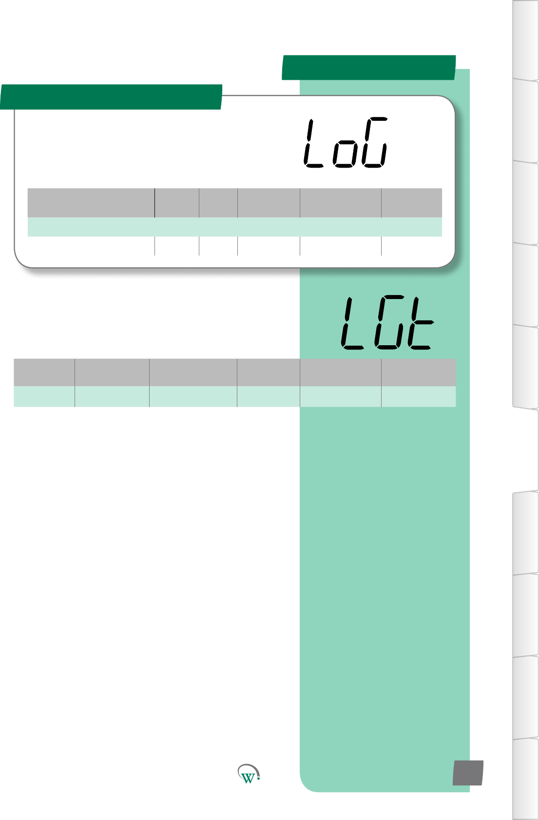
PleaseP
PARAMETERS
Parameter Name Digital
Display Pages Increments
&Units Range Default
Timers and Counter
LoggingInterval LGt 73 mins 30 to 1440 30
Digital
Display
Funconal
Category ParameterRange Increments
&Units Default Related Menus
LGt Logging 30 to 1440 mins 1 min 30 mins not applicable
Logging Menu (LoG)
TABLE OF
CONTENTS
INTRODUCTION
& WARNINGS
DESCRIPTION
& INSTALLATION
FRONT PANEL
USER INTERFACE
GRAPHICAL
USER INTERFACE
PARAMETERS
UPGRADING
FIRMWARE
FAULTS &
ALARMS
TECHNICAL
SPECIFICATION
APPENDICES
PD0006 V2.0 – 08 Jan 2016 73
TheLoggingParametersdenehowdataisloggedandsent
to the cloud
LOGGING INTERVAL (LGt)
Setsthemeinminsbetweenloggingofstascs.Stascs
areuploadedviatheassettrackingapplicaontothecloudfor
viewingofhistoricalstascs.
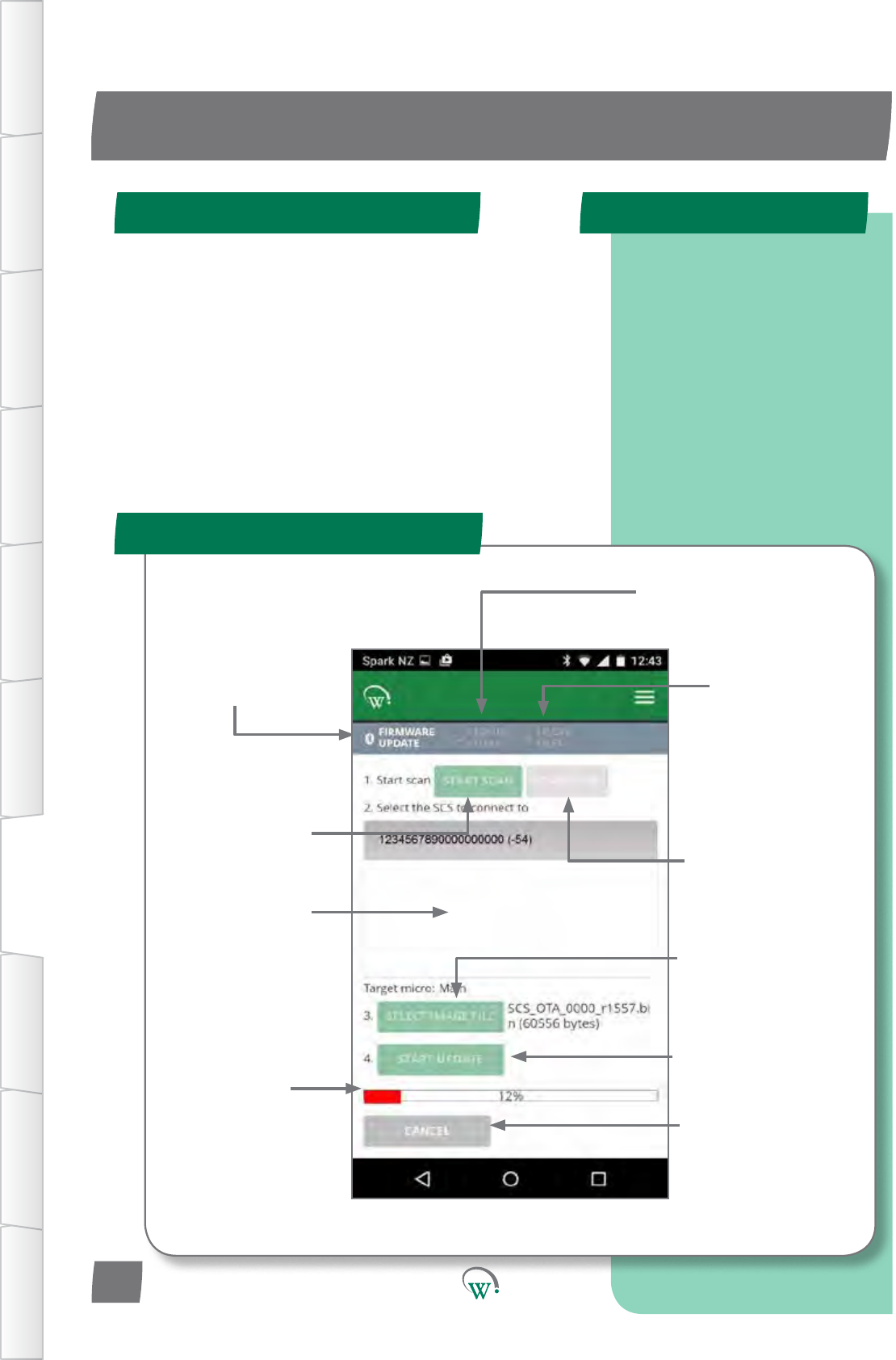
Navigatesto
this Screen
Screenforselecon
of Cloud stored
Firmware Files
Screen for
management
of locally stored
Firmware Files
IniatestheSCS
scanningprocess Stops the SCS
scanningprocess
Windowshowing
visible SCSs Forseleconof
rmwareletobere-
ashedontoSCS
Toiniatethe
reashingprocess
ReashingStatus
bar
To terminate
thereashing
process
UPGRADING FIRMWARE
Quick Read
FIRMWARE UPDATE Screen
SCS Programming Steps
TABLE OF
CONTENTS
INTRODUCTION
& WARNINGS
DESCRIPTION
& INSTALLATION
FRONT PANEL
USER INTERFACE
GRAPHICAL
USER INTERFACE PARAMETERS UPGRADING
FIRMWARE
FAULTS &
ALARMS
TECHNICAL
SPECIFICATION APPENDICES
Step 1: Select controller.
Step 2: Select Bin File.
Step 3: Connect.
Step4:VerifyandProgram.
PD0006 V2.0 – 08 Jan 2016
74
Firmware can be updated from either the mobile or desktop
app. The steps are the same for both. Screenshots used are
from the mobile app, but look the same on the desktop app
The SCS contains two microprocessors.
• Hi-side micro
Responsibleforallvoltage,powerandcurrent
monitoringandS1andS2switching
• Main micro
Responsibleforallcontrolalgorithms
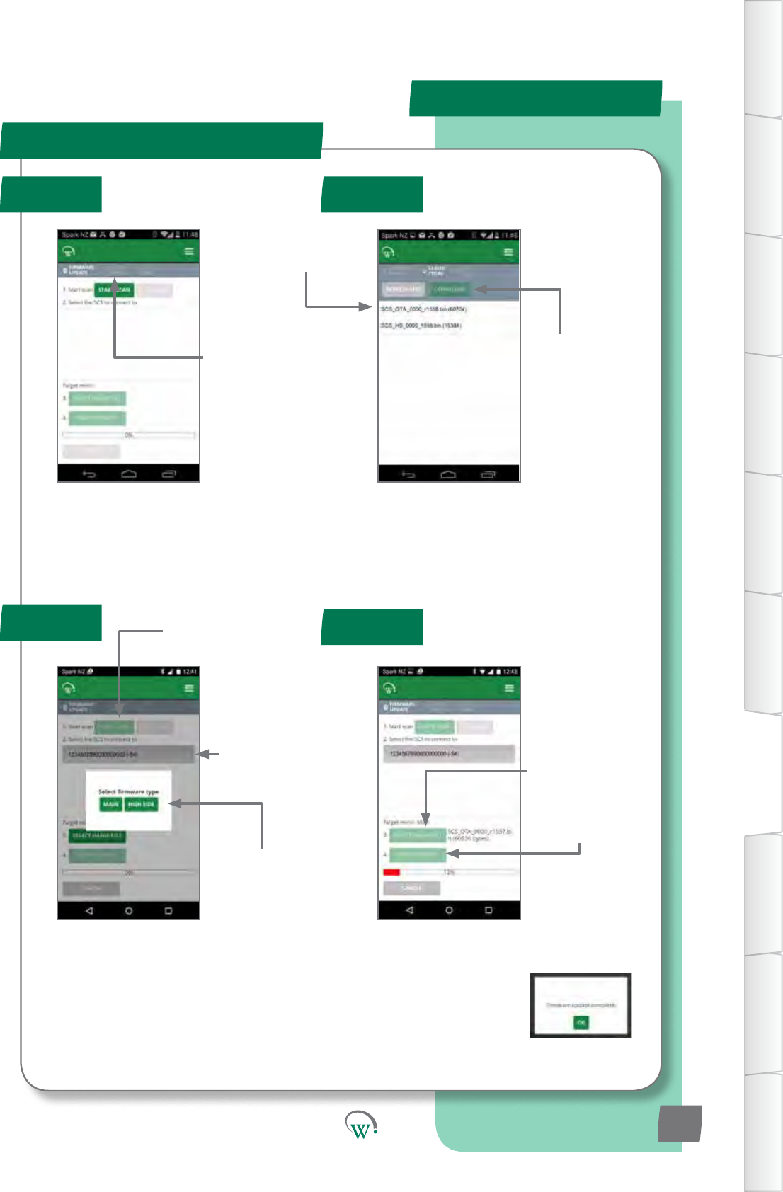
Note:
Ifyouchoose“MainMicro”,theSCSwill
resetitself,anddisplay“OtA”,whichmeans
itisreadytoupgradethemainmicro.
*Forhi-sideupgrades,earlyversionsofcoderequireanaddionalstep
notdocumentedhere.PleasecontactWellingtonforfurtherdetails
TABLE OF
CONTENTS
INTRODUCTION
& WARNINGS
DESCRIPTION
& INSTALLATION
FRONT PANEL
USER INTERFACE
GRAPHICAL
USER INTERFACE
PARAMETERS
UPGRADING
FIRMWARE
FAULTS &
ALARMS
TECHNICAL
SPECIFICATION
APPENDICES
PD0006 V2.0 – 08 Jan 2016 75
Step 2a:
Selectthele
you want to use
Note:
SCS_OTAareMainmicroles
SCS_HSareHi-sidemicroles
UPDATE PROCESS
Step 1 Step 2
Step 4
Step 3
Step 1:
Select Cloud
Stored Firmware
Files
Step 3a:
Startscanningfor
SCStoupgrade
Step 3b:
SelectSCStoUpgrade
(Bluetooth Indicator will
ashonselectedSCSonce
successfully connected)
Step 3c:
Choose which
micro*toupgrade
Step 2b:
Choose
DOWNLOAD
Step 4c:
Ensure“FirmwareUpdateComplete”is
displayedaerprogramming.Otherwise,
youwillneedtotryagain.
Step 4a:
Select Locally
Stored Firmware
leforUpgrade
Step 4b:
Starttheupgrade
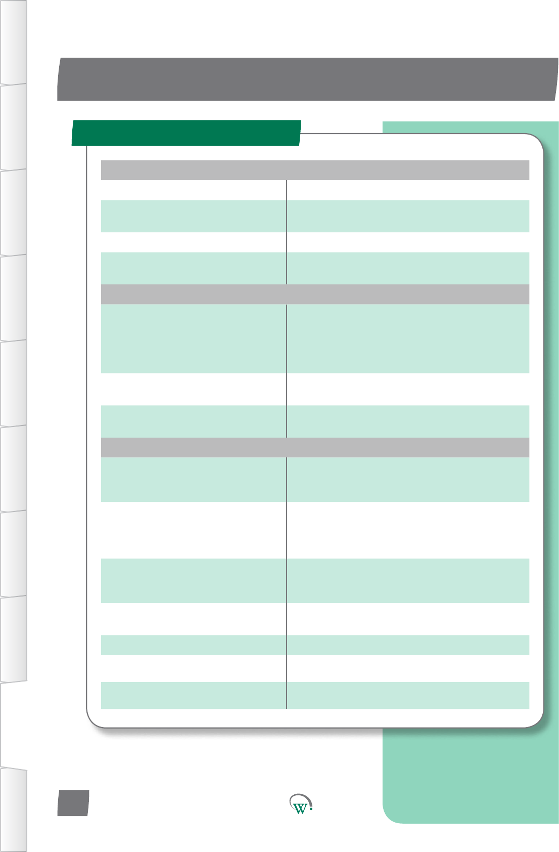
POWER
Power Supply 90 - 240Vac +10/-15% 50/60Hz
Input Connectors 6.08mm x 0.81mm QC tabs
Maximum rated current per terminal 12A
Power Consumption 3.5W maximum
Voltage Protection Compressor Over Voltage Protection
Compressor Under Voltage Protection
HV OUTPUTS
Output Ratings
C: Switched 12Arms*
R: Switched 5Arms*
S1: Switched 0.4Arms* (Switched 0.6Arms)**
S2: Switched 0.4Arms* (Switched 0.6Arms)**
Maximum total rated current 12A
Relay Operating Cycles EN60730-1: 30,000 operations
UL: 30,000 operations
Output Connectors 6.08mm x 0.81mm QC tabs
Maximum cable length: 10m
LV INPUTS/OUTPUTS
Sensor Temperature Range -50°C to 90°C @ 0.1°C
(-50°C to 300°C measurement range, limited
only by NTC capability)
Ratings
SELV
Digital 0 - 5V i/p
Analog NTC i/p
5V, 100mA o/p (AD4 only)
LV Connectors 2-way Stocko 7234-202-000-960-000-00-G
5-way Stocko 7234-005-000-960-000-00-G
Maximum cable length: 10m***
Supported Temperature Sensors NTC - 1k to 15k @ 25°C, Beta Value 3400
to 4000
Supported Digital Inputs High impedence voltage input
PWM outputs 0 - 24Vdc, PWM, 1A (x4)
UART Half duplex and Full duplex
TECHNICAL SPECIFICATIONS
Technical Specicaon Table
TABLE OF
CONTENTS
INTRODUCTION
& WARNINGS
DESCRIPTION
& INSTALLATION
FRONT PANEL
USER INTERFACE
GRAPHICAL
USER INTERFACE PARAMETERS UPGRADING
FIRMWARE
FAULTS &
ALARMS
TECHNICAL
SPECIFICATION APPENDICES
PD0006 V2.0 – 08 Jan 2016
76
* At 55°C with 105°C wire or at 42°C with 90°C wire
**At 42°C with 105°C wire
*** 2m when not installed in a cabinet (EN55014-1)
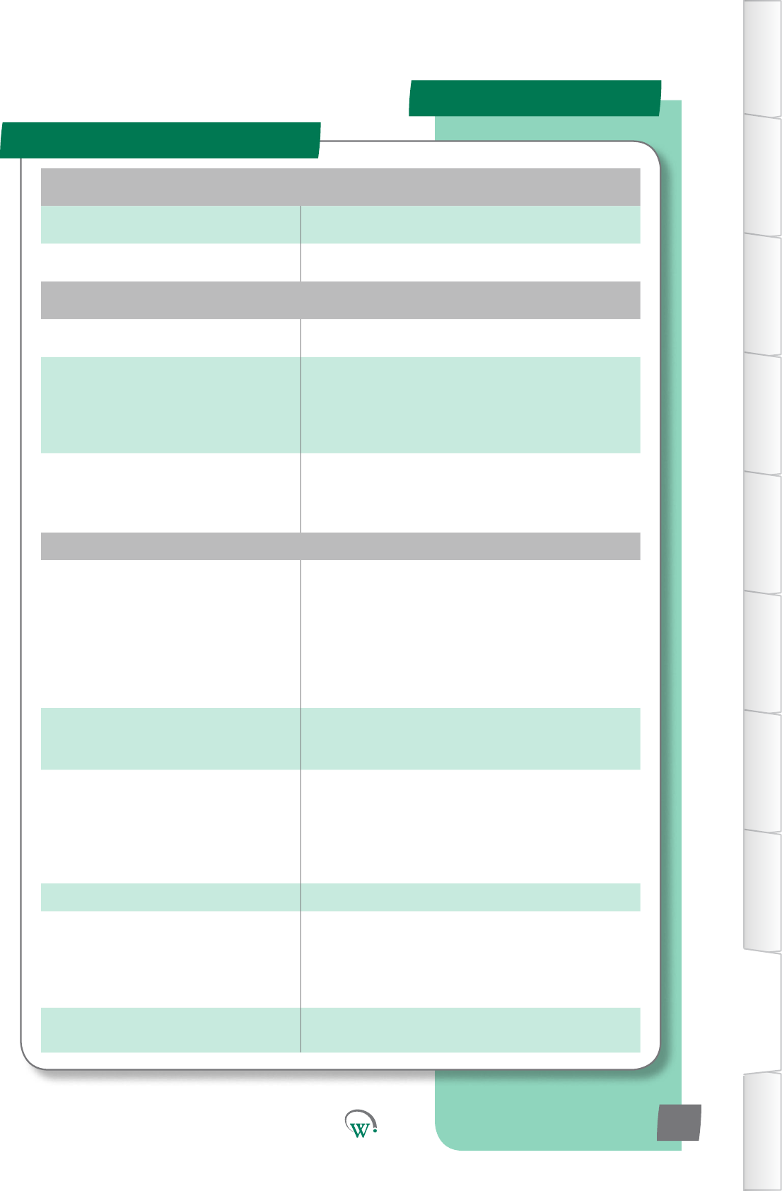
Specicaons Table - cont
SPECIFICATIONS
ENVIRONMENTAL
Operational Temperature Range -20°C to +55°C <90% RH non-condensing
Storage Conditions -40°C to +80°C <90% RH non-condensing
CONNECTIVITY
Bluetooth™ Capability Bluetooth™ LE
Supported Windows O/S
for GUI module
Windows XP SP 2
Windows Vista
Windows 7
Windows 8
Windows 8.1
Supported Mobile App Devices
Android with BT 4.0 and OS 4.4.3 or above
iPhone 4S or later
iPAD 3rd Gen or later
iPAD mini
PHYSICAL
Dimensions
SCS Overall Dimensions:
36.2mm (H) x 81.2mm (W) x 97.7mm (D)
Aperture Dimensions: 29mm (H) x 71mm
(W)
Maximum Mounting Panel Thickness: 9mm
Clearance Required for Escutcheon:
4mm above and below and 7mm to the left
and right of aperture hole.
Display 3 Digit LED Display, Digits 20mm high
Minimum Resolution: 0.1°C
Colours: Green, Blue, Red
Activity Indicators
Fan Indicator
Defrost Mode Indicator
Compressor Indicator
Night Mode Indicator
Alarm Indicator
Bluetooth™ Indicator
Interface 4 capacitive touch buttons
Housing Materials
Escutcheon: ABS, Color: Please enquire
Main Housing: PC, Color: Grey tinted clear
Seals: Silicone, Color: Black
Rear Cover: PC, Color: Gray tinted clear
Retaining Clips: POM, Color: Black
Cleaning Use only a damp cloth with neutral
detergents
TABLE OF
CONTENTS
INTRODUCTION
& WARNINGS
DESCRIPTION
& INSTALLATION
FRONT PANEL
USER INTERFACE
GRAPHICAL
USER INTERFACE
PARAMETERS
UPGRADING
FIRMWARE
FAULTS &
ALARMS
TECHNICAL
SPECIFICATION
APPENDICES
PD0006 V2.0 – 08 Jan 2016 77
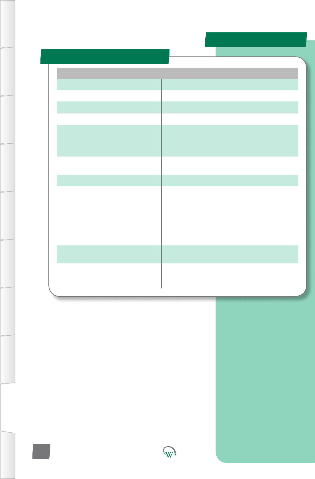
COMPLIANCE AND APPROVALS
Fire Rating UL94-V0
Electrical Insulation Rating Class II (when correctly installed)
Immunity against Voltage Surges 4000V (per EN61000-6-2)
Software Classication Class A
Safety Compliance
IEC-60335
IEC-60730*
UL-60730*
cUL*
Ingress Protection Front Panel: IP 68
Rear (Connectors enclosure): IP x5
Explosive Environments ATEX*, HC Compatible*
EMC
Immunity: EN6100-6-2, EN 301 489-1,
EN301 489-17
Emmissions: EN55014-1 , EN301 489-17 ,
EN300 328 V1.8.1
EN50371
FCC Part 15B and 15C EN 300 328
ICES-001, RSS-247, RSS-102
AS/NZS 4268, AS/NZS CISPR 22
European Directive: Restriction of
Hazardous Substances EU Directive 2002/95/EC (RoHS)
European Directive: Waste
Electrical and Electronic
Equipment EU Directive 2002/96/EC (WEEE)
*Pending
Specicaons Table - cont
SPECIFICATIONS
TABLE OF
CONTENTS
INTRODUCTION
& WARNINGS
DESCRIPTION
& INSTALLATION
FRONT PANEL
USER INTERFACE
GRAPHICAL
USER INTERFACE PARAMETERS UPGRADING
FIRMWARE
FAULTS &
ALARMS
TECHNICAL
SPECIFICATION APPENDICES
PD0006 V2.0 – 08 Jan 2016
78

FCC Declaraon
SPECIFICATIONS
TABLE OF
CONTENTS
INTRODUCTION
& WARNINGS
DESCRIPTION
& INSTALLATION
FRONT PANEL
USER INTERFACE
GRAPHICAL
USER INTERFACE
PARAMETERS
UPGRADING
FIRMWARE
FAULTS &
ALARMS
TECHNICAL
SPECIFICATION
APPENDICES
PD0006 V2.0 – 08 Jan 2016 79
Information to the user (FCC Part 15.105)
CLASS B DEVICE
This equipment has been tested and found to comply with the limits for a Class B digital
device, pursuant to Part 15 of the FCC Rules. These limits are designed to provide
reasonable protection against harmful interference in a residential installation. This
equipment generates, uses and can radiate radio frequency energy and, if not installed
and used in accordance with the instructions, may cause harmful interference to radio
communications. However, there is no guarantee that interference will not occur in a
particular installation. If this equipment does cause harmful interference to radio or
television reception, which can be determined by turning the equipment off and on,
the user is encourage to try to correct the interference by one or more of the following
measures:
• Reorient or relocate the receiving antenna
• Increase the separation between the equipment and receiver
• Connect the equipment into an outlet on a circuit different from that to which the
receiver is connected
• Consult the dealer or an experienced radio/TV technician for help
This device complies with Innovation, Science and Economic Development (ISED)
Canada’s licence-exempt RSS standards. Operation is subject to the following two
conditions:
1. This device may not cause interference; and
2. This device must accept any interference, including interference that may cause
undesired operation of the device.
DÉCLARATION DE CONFORMITÉ À LA FCC/IC
Cet appareil est conforme avec Innovation, Sciences et Developpement economic
Canada RSS standard exempts de licence(s). Son utilisation est soumise à Les deux
conditions suivantes:
1. cet appareil ne peut pas provoquer d’interférences et
2. cet appareil doit accepter Toute interférence, y compris les interférences qui peuvent
causer un mauvais fonctionnement du dispositif
CAN ICES-3 (B)/NMB-3(B)
Warning:AnychangesormodicaonsnotexpressivelyapprovedbyWellingtonDrive
TechnologiesLtdcouldvoidtheuser’sauthoritytooperatethisequipment

AC AlternangCurrent.
Acvity Anacvityisdenedasahumaninteraconwiththecabinet,
suchasopeningthecabinetdoortoaccesstheproductinside.
AcvitySensorState Usinginputsensorstodetermineiftherehasbeenanyacvity
orinteraconwiththecoolerunit.
Alarm Anaudibleorvisualsignalfromthecontrollerwhichwarnsthat
one or more parameters are outside of requirements.
Ambient Temperature Theaverageairtemperatureoutsideofthecoolerunit.
ATEX Mark TheATEXMarksigniesthattheproductconformstothe
relevantcategorystandardsfordeviceslocatedinpotenally
explosive environments, required by the European Economic
Area (EEA).
CCC Mark TheCCCMarksigniesthattheproductconformstothe
relevant product standards required by China.
CE Mark ConformitéEuropéenne.TheCEmarksigniesthattheproduct
conformstoallapplicableEuropeanDirecvesrequiredbythe
European Economic Area (EEA).
Compressor Adeviceforcompressingtherefrigerantmediumtochangeit
from vapour to liquid in the condenser coil.
Compressor Inlet Temperature The temperature detected on the outside of the compressor
inlet.
Condenser Thepartoftherefrigeraonsystemwheretherefrigeraon
mediumchangesphasefromvapourtoliquidthroughexternal
cooling.
Conguraon Aconguraonofagivenparameteriswhereaparcular
sengorvalueofaparameterhasbeensavedintotheSCS
Connectcontroller.Theparameteristhensaidtobecongured.
GLOSSARY
DenionTerm Used
TABLE OF
CONTENTS
INTRODUCTION
& WARNINGS
DESCRIPTION
& INSTALLATION
FRONT PANEL
USER INTERFACE
GRAPHICAL
USER INTERFACE PARAMETERS UPGRADING
FIRMWARE
FAULTS &
ALARMS
TECHNICAL
SPECIFICATION APPENDICES
PD0006 V2.0 – 08 Jan 2016
80

Control Probe An input device which provides data about a parameter.
Cooler Unit Theunitcontainingtherefrigeraonsystemandaninsulated
spaceforstoringanddisplayingproduct.
Counts Countsarethenumberofrecordedinstancesofaparcular
event, most usually associated with Alarm Parameters.
cUL Mark ThecULMarksigniesthattheproductconformstothe
relevant safety compliance required by the USA and Canada.
DC Direct Current.
Defrost Cycle Amodewheretherefrigeraonsystemswitchesothe
compressor to defrost the evaporator coil. This may be assisted
byheangandbytheevaporatorfanblowingairacrossthe
evaporator coil.
Diagnoscs Theprocessofanalyzingdatafromthecontrollertodetermine
thecurrentfunconoftheunit,parcularlyforinialsetupand
faultnding.
Dierenal Usedtomoderate,modifyorcalibrateagivenparameter,a
Dierenalisanosetdierencebetweentheusualupperand
lowervaluesoftheparameterandthepointwheresomethingis
triggered.
Duty Cycle TheraoofCompressoronmetoome.
EnergyManagement Acategoryofparametersconcernedwithenergyeciency.
EUDirecve2002/95/EC(RoHS) TheEUDirecvewhichgovernstheRestriconofHazardous
Substances(RoHS)ingoods.Thisdirecveiscloselylinkedwith
theWasteElectricalandElectronicEquipmentdirecve(WEEE).
EUDirecve2002/96/EC(WEEE) TheWasteElectricalandElectronicEquipmentdirecve(WEEE),
whichgovernsthecollecon,recyclinganddisposalofelectrical
andelectronicgoods.Thisdirecveiscloselylinkedwiththe
RestriconofHazardousSubstancesdirecve(RoHS).
Evaporator Fan The fan which is used to blow internal air over the evaporator
coil.Theevaporatorcoiltakesheatawayfromtheair,cooling
the air down.
DenionTerm Used
TABLE OF
CONTENTS
INTRODUCTION
& WARNINGS
DESCRIPTION
& INSTALLATION
FRONT PANEL
USER INTERFACE
GRAPHICAL
USER INTERFACE
PARAMETERS
UPGRADING
FIRMWARE
FAULTS &
ALARMS
TECHNICAL
SPECIFICATION
APPENDICES
PD0006 V2.0 – 08 Jan 2016 81

Evaporator Temperature The temperature detected on the outside of the evaporator coil.
GUI Graphical User Interface.
HACCP HazardAnalysis&CricalControlPointsisaprevenve
approachtofoodsafetyandstorageofmedicines,where
refrigeraoncontrolisrecognizedasacricalcontrolpoint.
HCCompable Suitableforusewithammablerefrigerantsinrefrigerators
complyingwithIEC60335-2-89.
HighVoltage Anypartoftherefrigeraonsystemwhichoperatesonvoltages
thatarehazardous.
Impedence Theopposiontotheowofelectricalcurrentinanelectrical
circuitwhenavoltageisapplied.
Input Ports (i/p) These are the connector ports on the back of the controller unit
forinboundcontrolsignals.
Internal Temperature The temperature detected inside the cooler unit where the
product is placed.
IRAM Mark TheIRAMMarksigniesthattheproductconformstothe
relevantproductstandardsrequiredbyArgenna.
LED LightEmingDiode.
N.C. NotConnected',inrelaontotheHardwareSetUpparameters.
Normal Mode Thestandardautomacrunningmode.
NSF Mark TheNSFMarksigniesthattheproductconformstothe
relevantfoodsafetyregulaonsfromtheindependentNSF
organisaon.
OEM OriginalEquipmentManufacturer.
DenionTerm Used
TABLE OF
CONTENTS
INTRODUCTION
& WARNINGS
DESCRIPTION
& INSTALLATION
FRONT PANEL
USER INTERFACE
GRAPHICAL
USER INTERFACE PARAMETERS UPGRADING
FIRMWARE
FAULTS &
ALARMS
TECHNICAL
SPECIFICATION APPENDICES
PD0006 V2.0 – 08 Jan 2016
82

Output Ports (o/p) These are the connector ports on the back of the controller unit
foroutboundsignalstocontrolleddevices.
OverVoltage Astatewherethesupplypowervoltageishigherthanthe
designlimitsoftheequipment.
Parameter Aquanablemeasureofsomekind.Parametersareusedto
controltherefrigeraonsystem.Examplesofparametersare
temperatureandme.
Perishable Mode Themodeusedwhenthegoodsbeingstoredcanbedamaged
ifnotkeptconnuouslycool,forexamplemedicinesanddairy
products.Standbymodesaredisabled.Thisfunconcomplies
withrulesandregulaonsunderHACCP.
Probes Probesaredeviceswhichgenerateasignalusedtocontrol
devicesasaresultofadetectedenvironmentalchange.
Probesareakindofsensor,andthetwotermsareoenused
interchangibly.
Products Productsaretheitemsbeingstoredinsidetherefrigerated
cabinet, for example chilled drinks.
Pulldown Time Themetakenbetweenwhenthecompressorandevaporator
fanstartsworkingandwhenthecooledproductreachesthe
required temperature.
PWM PulseWidthModulaon,amethodofcontrollingsupplied
powerusinghighfrequencyswitching.
RefrigeraonSystem Thecomponentscomprisingthecompleterefrigeraoncircuit,
includingcontroller,evaporator,expansionvalve,condenser,
compressor and evaporator fan.
Relays Thesearethehighvoltageswitchedconnectorsonthebackof
thecontrollerunitforcontrollinghighvoltageACdevices,such
as the compressor and evaporator fan.
SELV SafetyExtraLowVoltage.Anelectricalsysteminwhichthe
voltagecannoytexceed50Vrmsundernormalcondions,and
undersingle-faultcondions.
DenionTerm Used
TABLE OF
CONTENTS
INTRODUCTION
& WARNINGS
DESCRIPTION
& INSTALLATION
FRONT PANEL
USER INTERFACE
GRAPHICAL
USER INTERFACE
PARAMETERS
UPGRADING
FIRMWARE
FAULTS &
ALARMS
TECHNICAL
SPECIFICATION
APPENDICES
PD0006 V2.0 – 08 Jan 2016 83

Sensor Sensorsaredeviceswhichgenerateasignalusedtocontrol
devicesasaresultofadetectedenvironmentalchange.
Probesareakindofsensor,andthetwotermsareoenused
interchangibly.
Setpoint Thepreferredtargetvalueforagivenparameter.
SoStart Acontrolledmedelaybetweenwhenthepowercomesonand
when the compressor is allowed to start.
Standby Modes Asequenceofcontrolmodesusedtosaveenergyduring
periods of lower use.
States Thestateofadevice(eg;'on'or'oFF')isusedbytheSCS
Connectcontrolertomakelogicdecisionswhencontrollingthe
device.
Terminal Alarm ATerminalAlarmiscausedbyasignicantfault.Ifthe
Terminal Alarm fault count exceeds a certain number, then the
refrigeraonsystemisshutdowntoprotectitagainstdamage.
Thermostat Aswitchorsignaldevice,acvatedbychangesintemperature.
TransionModes Aseriesof“inbetween”modesthatcanbeusedtoadjust
set-pointandlighnglevels,withoutfullychangingbetween
Normal and Standby mode.
UL Mark TheULMarksigniesthattheproductconformstothe
relevant safety compliance standard published by Underwriters
Laboratories Inc.
UnderVoltage Astatewherethesupplypowervoltageislowerthanthe
requirements of the equipment.
VDE Mark TheVDEMarksigniesthattheproductconformstothe
relevantelectricalequipmentsafetyregulaonsfromthe
independentVDEorganisaon.
DenionTerm Used
TABLE OF
CONTENTS
INTRODUCTION
& WARNINGS
DESCRIPTION
& INSTALLATION
FRONT PANEL
USER INTERFACE
GRAPHICAL
USER INTERFACE PARAMETERS UPGRADING
FIRMWARE
FAULTS &
ALARMS
TECHNICAL
SPECIFICATION APPENDICES
PD0006 V2.0 – 08 Jan 2016
84

Quick Read
FAULTS AND ALARMS
TABLE OF
CONTENTS
INTRODUCTION
& WARNINGS
DESCRIPTION
& INSTALLATION
FRONT PANEL
USER INTERFACE
GRAPHICAL
USER INTERFACE
PARAMETERS
UPGRADING
FIRMWARE
FAULTS &
ALARMS
TECHNICAL
SPECIFICATION
APPENDICES
PD0006 V2.0 – 08 Jan 2016 85
The SCS Connectcontainsthefollowingfaultprotecon
mechanisms:
FAULTS (Displays Alarm Symbol)
Door Fail
Excessive Door Open Counts
OverVoltage
UnderVoltage
Condenser Overtemp
Maximum Compressor Starts in 1hr *
ALARMS (Displays Alarm Symbol and Alarm Code)
DoorLeOpenAlarm(AL1)
Excessive Condenser Overtemp (AL15) *
NTC Failure (AL17)
RefrigeraonFail(AL19)
Return Air Under Temp (AL20)
Triac Overcurrent (AL22 , AL23)
FAULTSarelogged,butdonotaectproducttemperature,and
requirenoaconbytheShopOwner.
ALARMSarelogged,buttheycanresultinwarmproduct.
Some faults can be cleared by the store owner, but others can
only be cleared by a service technician.
* Not yet implemented
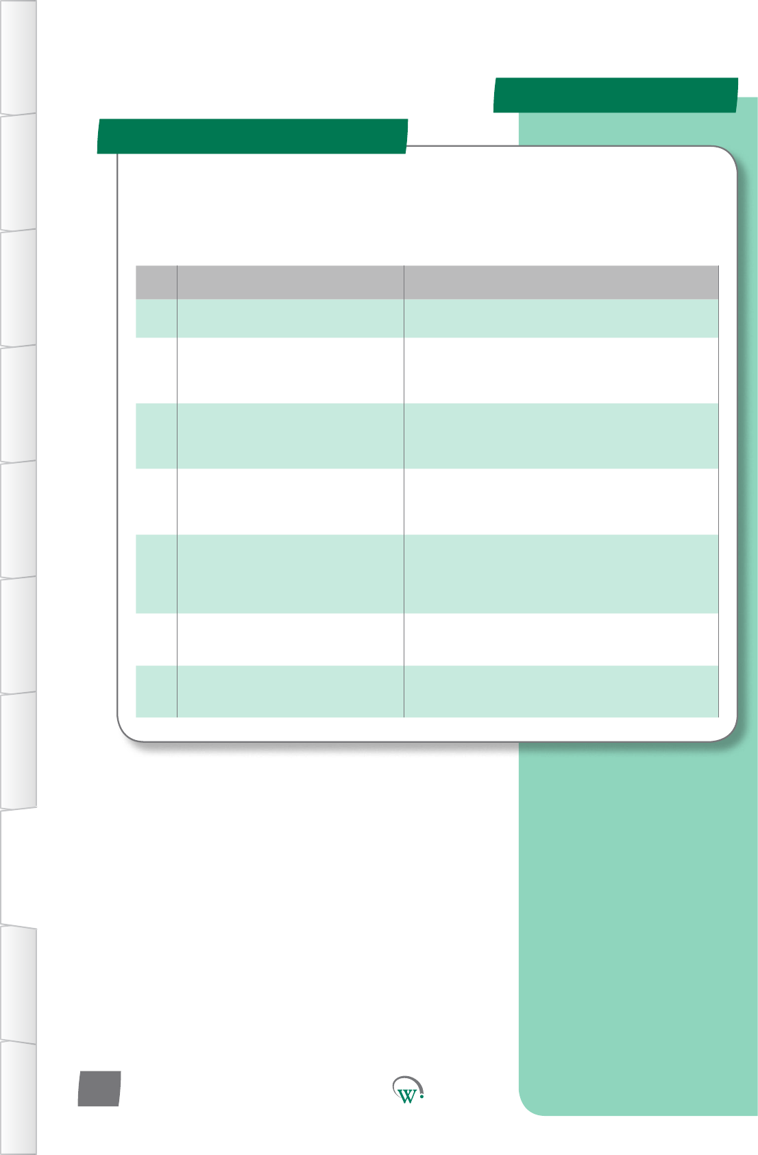
Fault
Code Fault PossibleCausesandAcons
1Door Open
Thedoorhasbeenleopen
Closingthedoorwillclearthisfault.Thedoormaynotbe
closeproperlyduetosagging,andmayrequireadjustment.
15
Excessive Condenser Overtemp
Thecondenserhasseenmulple
overtemperaturecondionsinashortspace
ofme.
Checkthatnothingisblockingthecondensere.g.boxes,and
thenresetbypowercycling.Ifthisfaultconnuestohappen,
checkthatthecondenserfanisfunconingcorrectly.
17
NTC Failure
Either the main temperature sensor probe or
thecondensertemperatureprobe(ifed)
has failed.
Thetemperatureprobeneedsreplacing.Thesystemwillnot
run while this fault is present.
19
Refrigeraon Failure
Thecompressorhasrunconnuouslyforthe
conguredmewithoutreachingthesetpint
temperature
Mulplepossibilies,prevenngthesystemfromacheiving
temperature.
Thesystemwillnotresetbypowercycling,onlybywringto
the“ClearTerminalAlarm”parameter(seepage72)
20
Return Air Under Temp
The temperature has dropped below the
normalmodesetpointbyaspeciedamount
Theproducttemperaturekeepsgengcolder,evenwhen
thecompressoristurnedo.Checkthecompressoris
correctlywired,andthatthe“CompressorState”parameter
is set correctly. Can also be due to an external secondary
compressorrelayfailure.(Seepage67)
21 Triac S1 Overcurrent
TheloadingonS1drawstoomuchcurrent
Ahighcurrentcomponents,suchasthecompressor,has
incorrectly been connected to the S1 output. Check the
wiring.
22 Triac S2 Overcurrent
TheloadingonS1drawstoomuchcurrent
Ahighcurrentcomponents,suchasthecompressor,has
incorrectly been connected to the S1 output. Check the
wiring.
Alarms
Alarm Codes
TABLE OF
CONTENTS
INTRODUCTION
& WARNINGS
DESCRIPTION
& INSTALLATION
FRONT PANEL
USER INTERFACE
GRAPHICAL
USER INTERFACE PARAMETERS UPGRADING
FIRMWARE
FAULTS &
ALARMS
TECHNICAL
SPECIFICATION APPENDICES
PD0006 V2.0 – 08 Jan 2016
86
Repornganalarmearlywillminimisethedownmeof
the cooler. An alarm code should always be supplied when
repornganalarm.
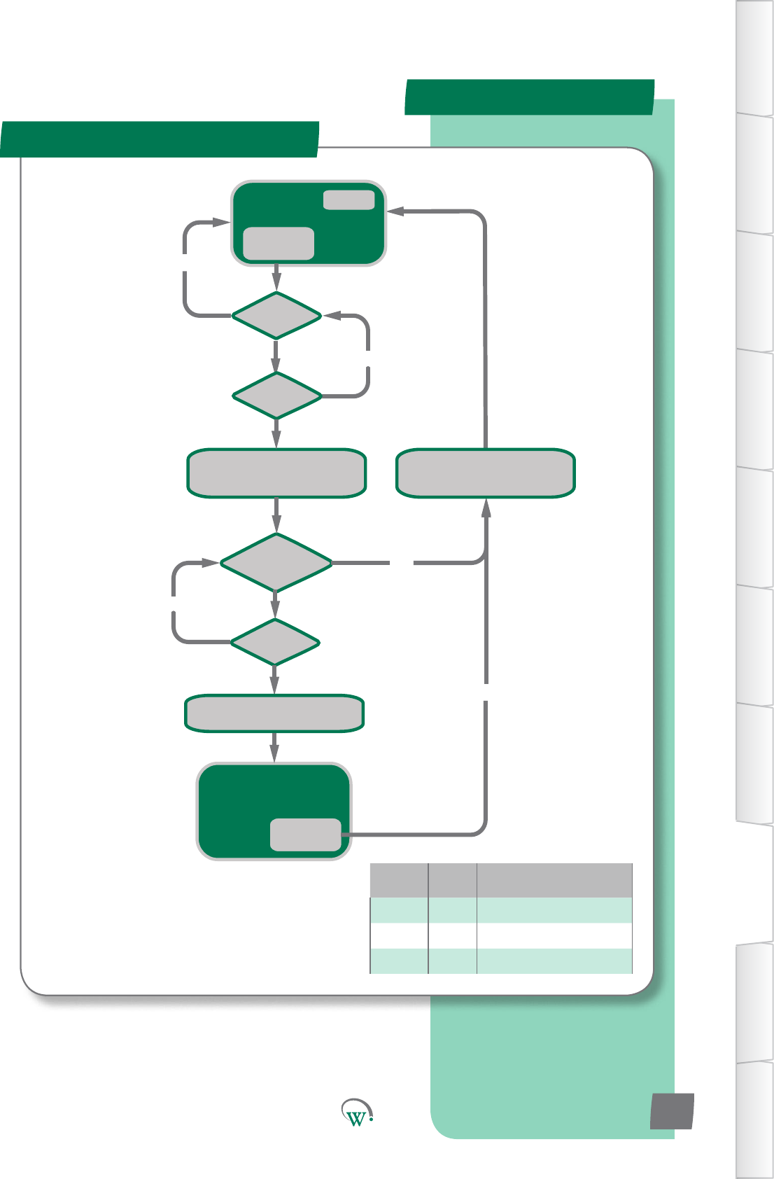
NORMAL
operation
dot = 0
Is dot > drd?
Is door closed?
Display AL1
Turn ON Alarm Symbol
Turn OFF Compressor
NO
YES
Is dot > dfd?
NO
YES
Is door open?
NO
Door Open
Event
NORMAL operation
Ignore door state
Alarm Symbol ON
Door Close
Event
Display temperature
RE-ENABLE Compressor
Display Temperature
Turn OFF Alarm Symbol
RE-ENABLE Compressor
Variable Type Descripon
dot Timer Door Open Time
drd Limit Door Open Delay
dfd Limit Door Fail Delay
Fault Logic
Door Open and Door Fail
TABLE OF
CONTENTS
INTRODUCTION
& WARNINGS
DESCRIPTION
& INSTALLATION
FRONT PANEL
USER INTERFACE
GRAPHICAL
USER INTERFACE
PARAMETERS
UPGRADING
FIRMWARE
FAULTS &
ALARMS
TECHNICAL
SPECIFICATION
APPENDICES
PD0006 V2.0 – 08 Jan 2016 87
*
* Compressor will not re-start unless it has
been off for the minimum off time
*
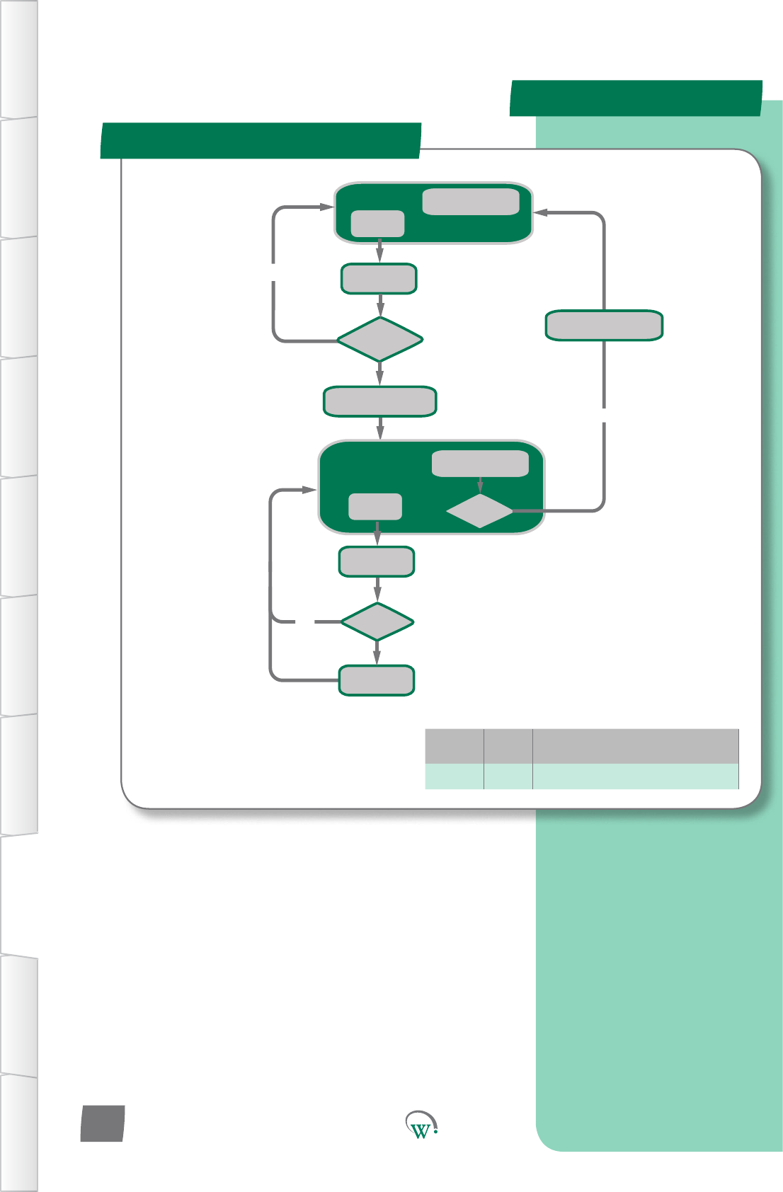
Normal Running
doC = doC + 60
YES
Is doC > 1800?
NO
Door Open
Event
Normal Running
Door Switch Ignored
Alarm Symbol Displayed
doC = doC + 60
NO
Door Open
Event
doC decrements
every 1 sec while > 0
Is doC = 0
doC decrements
every 1 sec while > 0
Is doC > 1800?
doC = doC + 60
Turn OFF Alarm Symbol
Turn ON Alarm Symbol
Variable Type Descripon
doc Limit Door Open Count
Fault Logic
Excessive Door Openings
TABLE OF
CONTENTS
INTRODUCTION
& WARNINGS
DESCRIPTION
& INSTALLATION
FRONT PANEL
USER INTERFACE
GRAPHICAL
USER INTERFACE PARAMETERS UPGRADING
FIRMWARE
FAULTS &
ALARMS
TECHNICAL
SPECIFICATION APPENDICES
PD0006 V2.0 – 08 Jan 2016
88
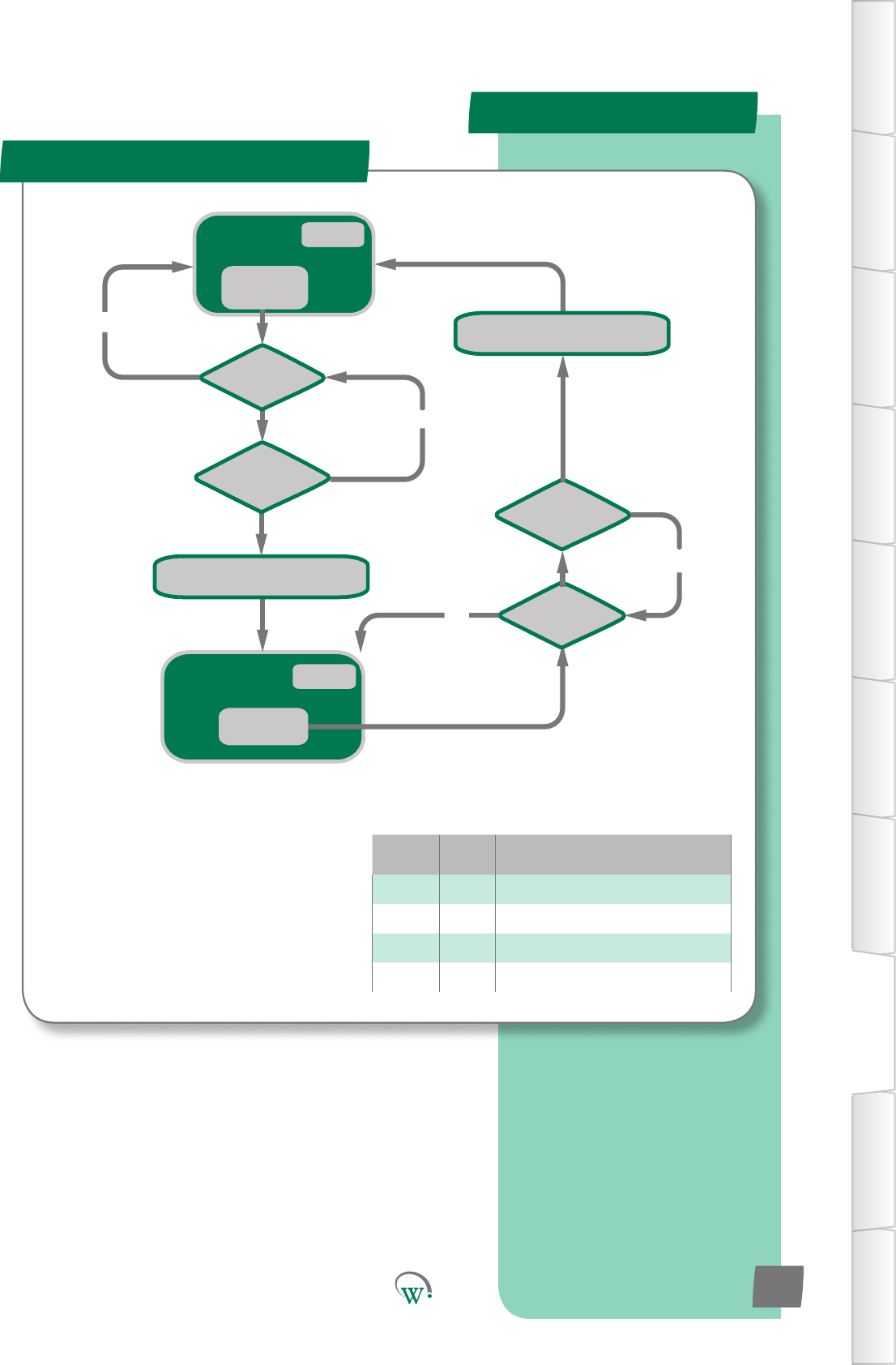
Alarm Symbol ON
Compressor OFF
Volts < hPC
Event
NORMAL
operation
Turn ON Alarm Symbol
Turn OFF Compressor
Turn OFF Alarm Symbol
RE-ENABLE Compressor
Is Volts > hPC?
Is tAmv > 10secs
NO
NO
Is Volts < hPC?
Is tBmv > 10secs
NO
NO
tAmv = 0
tBmv = 0
Volts > hPC
Event
Variable Type Descripon
Volts Input Currentvoltagelevel
hPC Limit MaximumRun/StartVoltage
tAmv Timer TimeABOVEmaximumvoltage
tBmv Timer TimeBELOWmaximumvoltage
Fault Logic
Over Voltage
TABLE OF
CONTENTS
INTRODUCTION
& WARNINGS
DESCRIPTION
& INSTALLATION
FRONT PANEL
USER INTERFACE
GRAPHICAL
USER INTERFACE
PARAMETERS
UPGRADING
FIRMWARE
FAULTS &
ALARMS
TECHNICAL
SPECIFICATION
APPENDICES
PD0006 V2.0 – 08 Jan 2016 89
*
* Compressor will not re-start unless it has
been off for the minimum off time
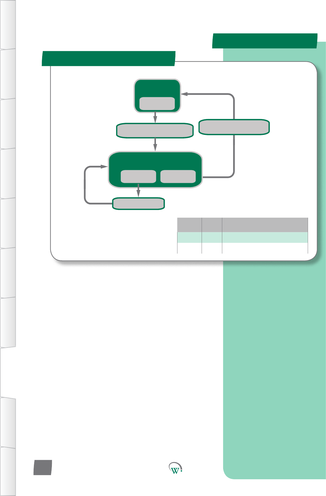
Alarm Symbol ON
Compressor starting DISABLED
Volts < uPC
Event
Volts > LPC
Event
NORMAL
operation
Turn ON Alarm Symbol
Starting DISABLED on Compressor
Volts < LPC
Event
Turn OFF Compressor
Turn OFF Alarm Symbol
RE-ENABLE Compressor
Variable Type Descripon
LPc Limit MinimumStartCompressorVoltage
uPC Limit MinimumRunCompressorVoltage
Fault Logic
Under Voltage
TABLE OF
CONTENTS
INTRODUCTION
& WARNINGS
DESCRIPTION
& INSTALLATION
FRONT PANEL
USER INTERFACE
GRAPHICAL
USER INTERFACE PARAMETERS UPGRADING
FIRMWARE
FAULTS &
ALARMS
TECHNICAL
SPECIFICATION APPENDICES
PD0006 V2.0 – 08 Jan 2016
90
*
* Compressor will not re-start unless it has
been off for the minimum off time
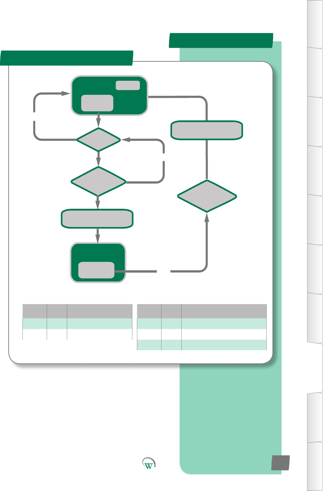
Is CT > Cht?
Is Ott > htd
Turn ON Alarm Symbol
Turn OFF Compressor
NO
NO
Wait 3 mins
Normal
Running
CT > Cht
Event
Ott = 0
Compressor OFF
Alarm Symbol ON
CT < Cht-htF
Event YES
Turn OFF Alarm Symbol
RE-ENABLE Compressor
Variable Type Descripon
Cht Limit CondenserHighTemperatureLimit
htd Limit HighTemperatureDelay
htF Limit HighTemperatureDierenal
Variable Type Descripon
CT Input Condenser Temperature
o Timer Over Temperature Timer
Fault Logic
Condenser Over Temp
TABLE OF
CONTENTS
INTRODUCTION
& WARNINGS
DESCRIPTION
& INSTALLATION
FRONT PANEL
USER INTERFACE
GRAPHICAL
USER INTERFACE
PARAMETERS
UPGRADING
FIRMWARE
FAULTS &
ALARMS
TECHNICAL
SPECIFICATION
APPENDICES
PD0006 V2.0 – 08 Jan 2016 91
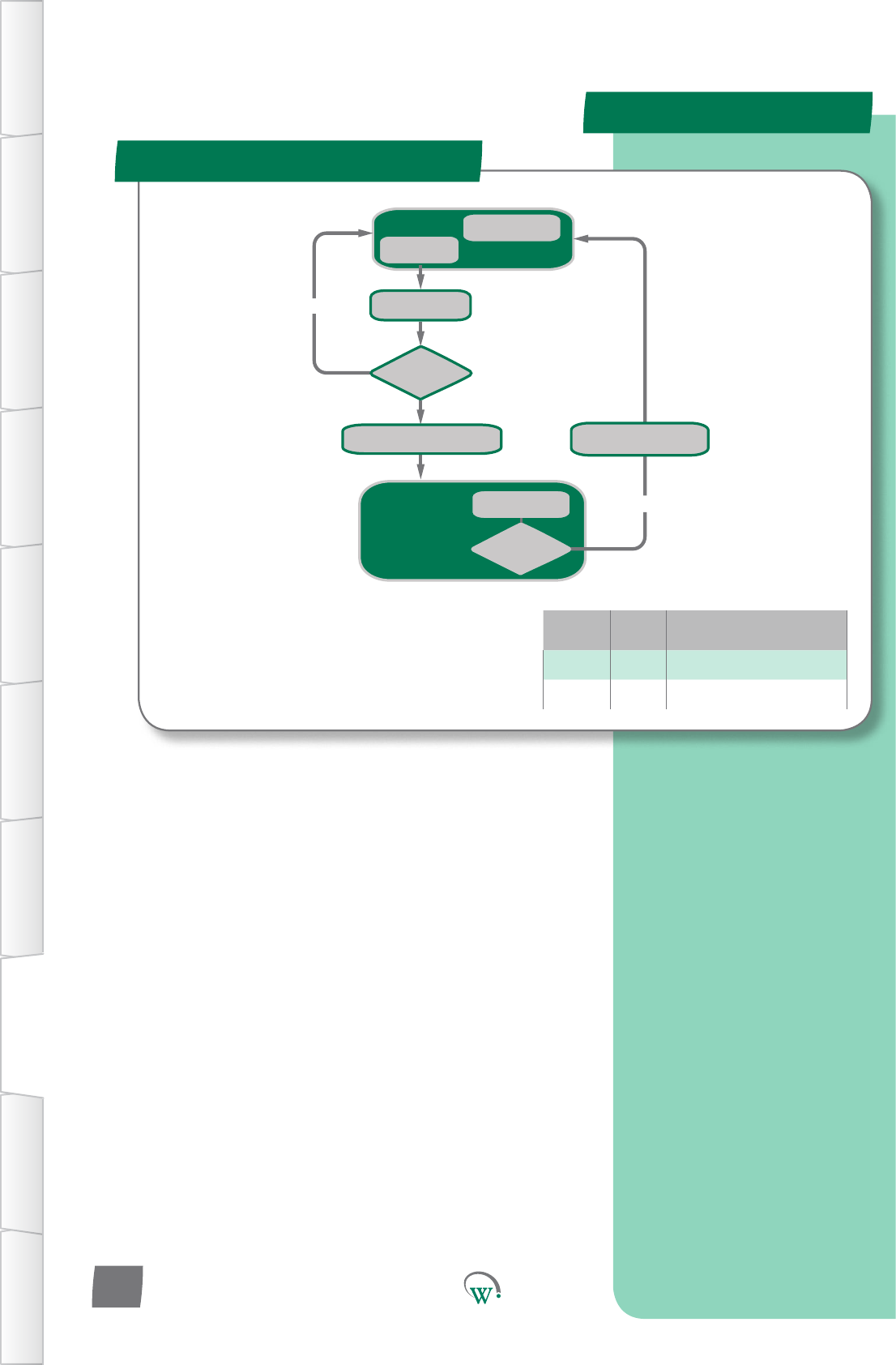
Variable Type Descripon
sPH Limit Compressor Starts per Hour
CST Timer Compressor Starts Timer
Normal Running
CST = CST + 3600/sPh
YES
Is CST >
(3600-(3600/sPh))?
NO
Compressor Start
Event
Alarm Code Displayed
Alarm Symbol ON
Compressor OFF
CST decrements
every 1 sec while > 0
CST decrements
every 1 sec while > 0
Turn OFF Alarm Symbol
RE-ENABLE Compressor
Turn ON Alarm Symbol
Turn OFF Compressor
Is CST <
(3600-(3600/sPh))?
Fault Logic
Max Compressor Starts in 1 hr
TABLE OF
CONTENTS
INTRODUCTION
& WARNINGS
DESCRIPTION
& INSTALLATION
FRONT PANEL
USER INTERFACE
GRAPHICAL
USER INTERFACE PARAMETERS UPGRADING
FIRMWARE
FAULTS &
ALARMS
TECHNICAL
SPECIFICATION APPENDICES
PD0006 V2.0 – 08 Jan 2016
92
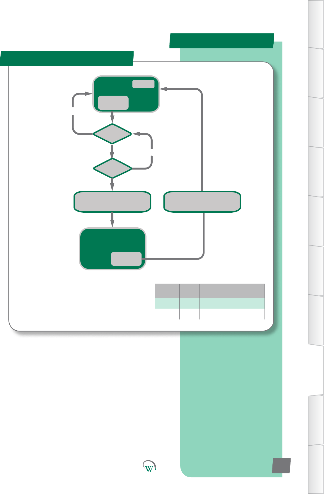
NORMAL
operation
dot = 0
Is dot > drd?
Display AL1
Turn ON Alarm Symbol
Turn OFF Compressor
NO
Is door open?
NO
Door Open
Event
Display AL1
Alarm Symbol ON
Compressor OFF
Door Close
Event
Display Temperature
Turn OFF Alarm Symbol
RE-ENABLE Compressor
Variable Type Descripon
dot Timer Door Open Time
drd Limit Door Open Delay
*
* Compressor will not re-start unless it has
been off for the minimum off time
Door Le Open
Alarm Logic
TABLE OF
CONTENTS
INTRODUCTION
& WARNINGS
DESCRIPTION
& INSTALLATION
FRONT PANEL
USER INTERFACE
GRAPHICAL
USER INTERFACE
PARAMETERS
UPGRADING
FIRMWARE
FAULTS &
ALARMS
TECHNICAL
SPECIFICATION
APPENDICES
PD0006 V2.0 – 08 Jan 2016 93
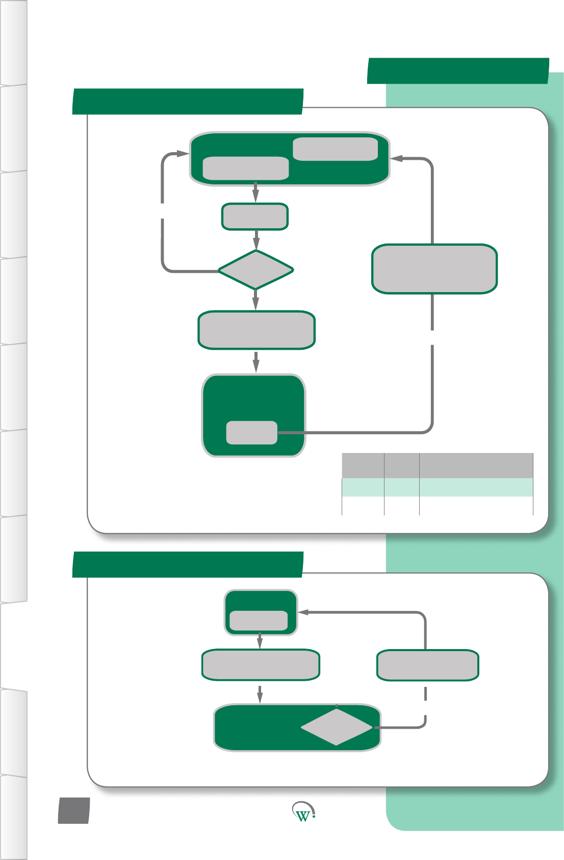
Normal Running
YES
NTC OC or SC
Event
Alarm Symbol Displayed
Alarm Code ON
Compressor OFF
Display Temperature
Turn OFF Alarm Symbol
RE-ENABLE Compressor
Display AL17
Turn ON Alarm Symbol
Compressor OFF
Is NTC
Reading correctly?
NTC Failure
Normal Running
Cot = Cot + 60
YES
Is Cot > 3600?
NO
Condenser Overtemp
Event
Alarm Code Displayed
Alarm Symbol ON
Compressor OFF
Power Cycle
Event
Cot decrements
every 1 sec while > 0
Display Temperature
Turn OFF Alarm Symbol
RE-ENABLE Compressor
Cot = 0
Display AL15
Tunr ON Alarm Symbol
Turn OFF compressor
Variable Type Descripon
SP Limit Current Mode Set-point
Cot Timer Compressor Overtemp Timer
*
* Compressor will not re-start unless it has
been off for the minimum off time
Alarm Logic
Excessive Condensor Over Temp
TABLE OF
CONTENTS
INTRODUCTION
& WARNINGS
DESCRIPTION
& INSTALLATION
FRONT PANEL
USER INTERFACE
GRAPHICAL
USER INTERFACE PARAMETERS UPGRADING
FIRMWARE
FAULTS &
ALARMS
TECHNICAL
SPECIFICATION APPENDICES
PD0006 V2.0 – 08 Jan 2016
94
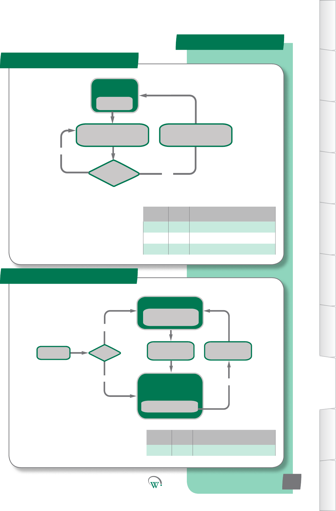
NORMAL
operation
Is Temp > SP + dIF?
Display AL20
Turn ON Alarm Symbol
Turn OFF all outputs
YES
NO
Temp < SP - rud
Event
Display Temperature
Turn OFF Alarm Symbol
RE-ENABLE all outputs
Variable Type Descripon
SP Limit Current Mode Set-point
di Limit Currentmodedierenal
rud Limit Return-AirUndertempDierenal
Normal Running
YES
Is AL19?
NO
Compressor Run for > rsF hrs
without reaching setpoint
Event
Refrigeration Failure
Alarm Code AL19 Displayed
Alarm Symbol Displayed
ALL outputs OFF
Clear Terminal Alarm set to 1
Event
Display AL19
Turn ON Alarm Symbol
Turn OFF all outputs
Power Cycle
YES
Display Temperature
Turn OFF Alarm Symbol
RE-ENABLE all outputs
Variable Type Descripon
rsF Limit RefrigeraonSystemFailureTime
Refrigeraon Failure
Alarm Logic
Return Air Under Temp
TABLE OF
CONTENTS
INTRODUCTION
& WARNINGS
DESCRIPTION
& INSTALLATION
FRONT PANEL
USER INTERFACE
GRAPHICAL
USER INTERFACE
PARAMETERS
UPGRADING
FIRMWARE
FAULTS &
ALARMS
TECHNICAL
SPECIFICATION
APPENDICES
PD0006 V2.0 – 08 Jan 2016 95
*
* Compressor will not re-start unless it has
been off for the minimum off time
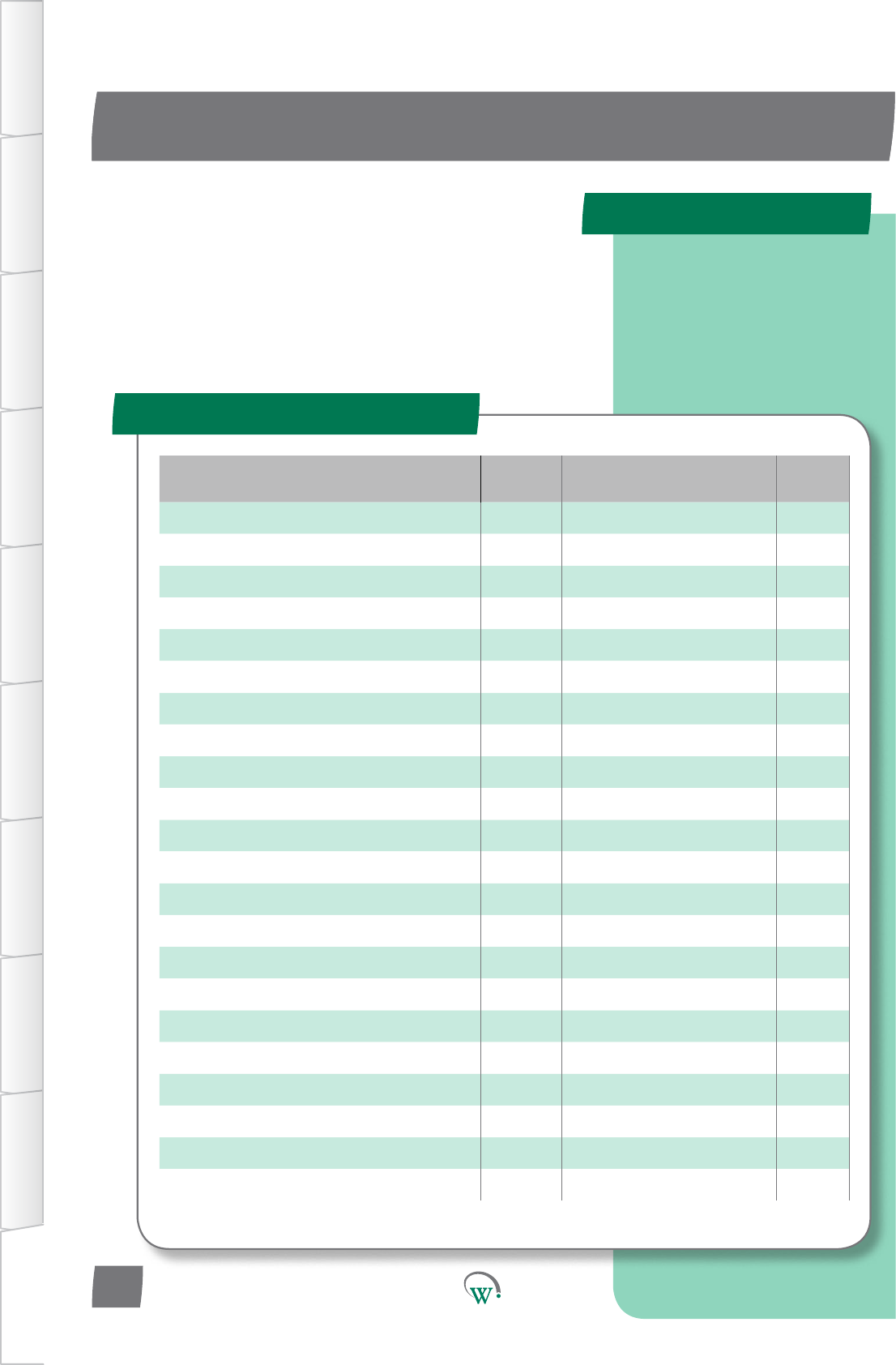
PARAMETER NAME SCS
DISPLAY MENU PAGES
AcvitySensorPortConguraon SCF Hardware Set-up 64
AD1 NTC Type Ad1 Hardware Set-up 65
AD2 NTC Type Ad2 Hardware Set-up 65
AD3 NTC Type Ad3 Hardware Set-up 66
AD4 NTC Type Ad4 Hardware Set-up 66
AD5 NTC Type Ad5 Hardware Set-up 66
Ambient Temperature Port tPt Hardware Set-up 62
Clear Terminal Alarm CtA General Alarms Menu 72
Compressor Body Temperature Port CPP Hardware Set-up 63
Compressor Inlet Temperature Port CtP Hardware Set-up 63
Compressor Maximum Starts per Hour CSh Compressor Menu 55
CompressorPortConguraon CPC Hardware Set-up 67
Compressor State CPS Hardware Set-up 67
CondenserFanDirecon CFd Hardware Set-up 68
CondenserFanPortConguraon CdC Hardware Set-up 68
Condenser Temperature Port CdP Hardware Set-up 62
Condensor Fan Control Type CCt Hardware Set-up 68
CondensorHighTemperatureLimit Cht Compressor Menu 68
ControlProbeCalibraonOset CAL Hardware Set-up 68
Control Probe response CPb Hardware Set-up 61
DefrostIniaonTemperature dIt Defrost 48
DefrostPortConguraon dFC Hardware Set-up 69
Quick Read
APPENDIX 1
Full Parameter List
TABLE OF
CONTENTS
INTRODUCTION
& WARNINGS
DESCRIPTION
& INSTALLATION
FRONT PANEL
USER INTERFACE
GRAPHICAL
USER INTERFACE PARAMETERS UPGRADING
FIRMWARE
FAULTS &
ALARMS
TECHNICAL
SPECIFICATION APPENDICES
Click on page numbers to go
to relevant section.
PD0006 V2.0 – 08 Jan 2016
96
Thefollowingtablelistsallcongurableparameters.In
electronicformat,clickonpagenumbersorthedisplaycode
togodirectlytotherelevantsecon.
PARAMETER NAME SCS
DISPLAY MENU PAGES
Defrost State dFS Hardware Set-up 69
DefrostTerminaontemperature d Defrost 48
Defrost Type dtP Defrost 49
Display Value - Defrost Cycle ddE Defrost 50
Display Value - Normal Mode dIS Normal Mode 30
Display Value - Standby Mode dSy Standby Mode 43
Door Open Delay drd Door Menu 52
DoorOpenEvapConnuousRunTemp FCr Door Menu 51
DoorSensorPortConguraon dSC Hardware Set-up 63
Door Switch State drS Hardware Set-up 63
DrippingTime dPt Defrost 49
Evaporator Coil Temperature Port ELt Hardware Set-up 68
Evaporator Fan Control type ECt Hardware Set-up 67
EvaporatorFanDirecon Efd Hardware Set-up 68
EvaporatorFanoTime-NormalMode FoF Normal Mode 51
Evaporator Fan on Time - Normal Mode Fot Normal Mode 30
EvaporatorFanPortConguraon EFC Hardware Set-up 67
HighTemperatureAlarmSetPoint htA Normal Mode 32
InacvityWaitTime-NormalMode Ytn Normal Mode 30
InacvityWaitTime-StandbyHoldMode yth Standby Mode 41
InacvityWaitTime-Transion1 yt1 Transion1Mode 34
InacvityWaitTime-Transion2 yt2 Transion2Mode 37
InacvityWaitTime-Transion3 yt3 Transion3Mode 45
LightState-ChannelA LEA Hardware Set-up 70
LightState-ChannelB LEb Hardware Set-up 71
LightState-ChannelC LEC Hardware Set-up 71
LightStateDoorOpen-ChannelA LdA Door Menu 52
LightStateDoorOpen-ChannelB Ldb Door Menu 52
LightStateDoorOpen-ChannelC LdC Door Menu 53
LightStateNormalMode-ChannelA LnA Normal Mode 31
LightStateNormalMode-ChannelB LnB Normal Mode 31
Full Parameter List- cont
APPENDIX 1
TABLE OF
CONTENTS
INTRODUCTION
& WARNINGS
DESCRIPTION
& INSTALLATION
FRONT PANEL
USER INTERFACE
GRAPHICAL
USER INTERFACE
PARAMETERS
UPGRADING
FIRMWARE
FAULTS &
ALARMS
TECHNICAL
SPECIFICATION
APPENDICES
PD0006 V2.0 – 08 Jan 2016 97
PARAMETER NAME SCS
DISPLAY MENU PAGES
LightStateNormalMode-ChannelC LnC Normal Mode 31
LightStateStandbyMode-ChannelA LSA Standby Mode 42
LightStateStandbyMode-ChannelB LSb Standby Mode 42
LightStateStandbyMode-ChannelC LSC Standby Mode 42
LightStateTransion1Mode-ChannelA L1A Transion1Mode 35
LightStateTransion1Mode-ChannelB L1b Transion1Mode 35
LightStateTransion1Mode-ChannelC L1C Transion1Mode 35
LightStateTransion2Mode-ChannelA L2A Transion2Mode 38
LightStateTransion2Mode-ChannelB L2b Transion2Mode 38
LightStateTransion2Mode-ChannelC L2C Transion2Mode 38
LightStateTransion3Mode-ChannelA L3A Transion3Mode 46
LightStateTransion3Mode-ChannelB L3b Transion3Mode 46
LightStateTransion3Mode-ChannelC L3C Transion3Mode 46
LighngPortConguraon-ChannelA LCA Hardware Set-up 69
LighngPortConguraon-ChannelB LCb Hardware Set-up 70
LighngPortConguraon-ChannelC LCC Hardware Set-up 70
LoggingInterval LGt Logging 73
Low Temperature Alarm Set Point LtA Normal Mode 32
MarkengMode tnG Standby Mode 43
Max user set point SPt Normal Mode 29
Maximum Defrost Cycle Time dCt Defrost 48
Maximum Defrost Interval dEI Defrost 49
Maximum Displayable Temperature dSt Display Menu 58
MaximumRun/StartCompressorVoltage hPC Supply Menu 56
Maximum Standby Time Sbt Standby Mode 41
Min user set point SP- Normal Mode 29
MinimumCompressorOTime Cot Compressor Menu 54
Minimum Displayable Temperature dP- Display Menu 58
MinimumStartCompressorVoltage LPC Supply Menu 56
NTC 1 Beta value n1b Hardware Set-up 64
Full Parameter List- cont
APPENDIX 1
TABLE OF
CONTENTS
INTRODUCTION
& WARNINGS
DESCRIPTION
& INSTALLATION
FRONT PANEL
USER INTERFACE
GRAPHICAL
USER INTERFACE PARAMETERS UPGRADING
FIRMWARE
FAULTS &
ALARMS
TECHNICAL
SPECIFICATION APPENDICES
PD0006 V2.0 – 08 Jan 2016
98
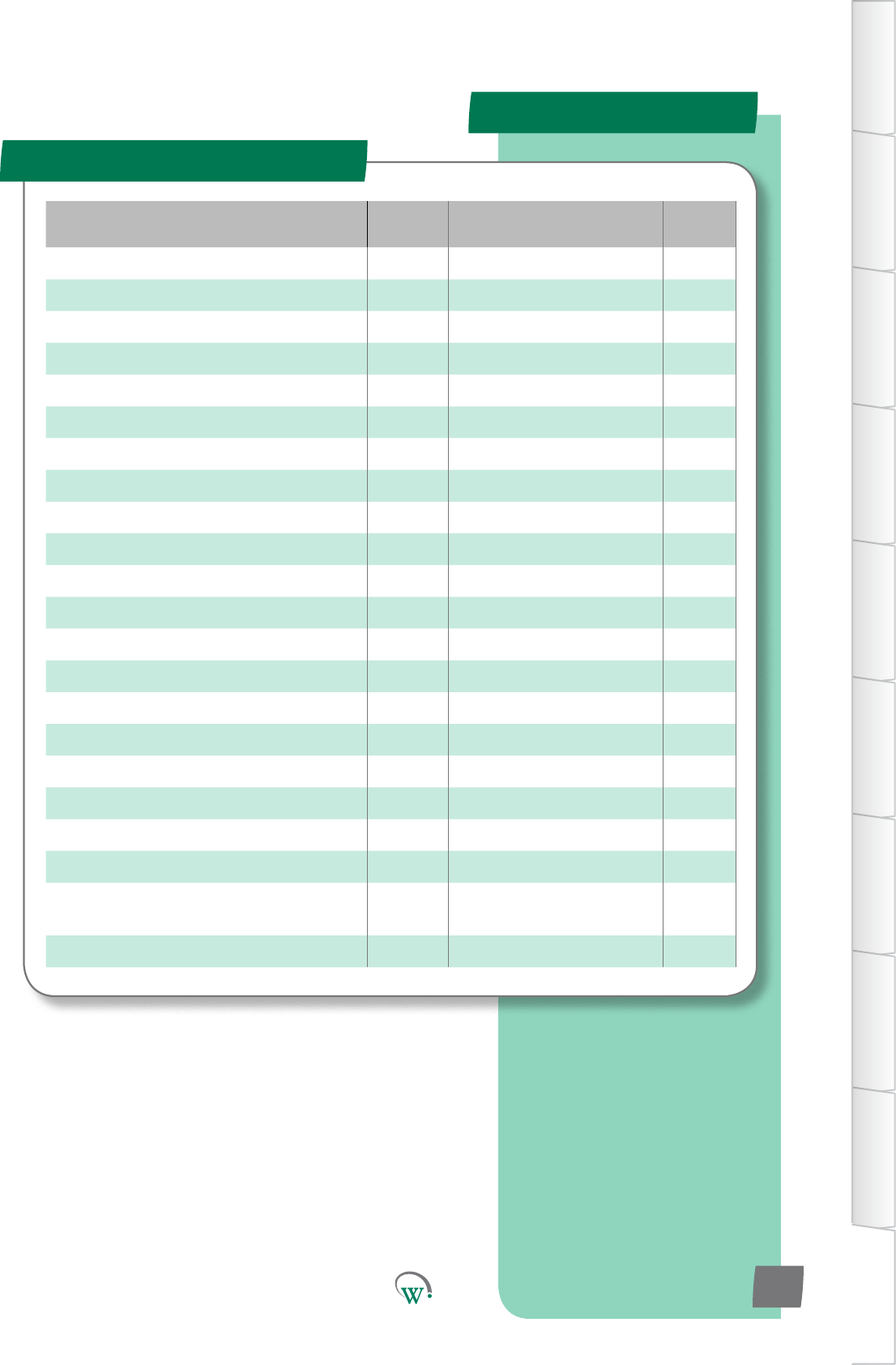
PARAMETER NAME SCS
DISPLAY MENU PAGES
NTC 1 Resistance n1r Hardware Set-up 65
NTC 2 Beta value n2b Hardware Set-up 65
NTC 2 Resistance n2r Hardware Set-up 65
OperaonalDierenal dIF Normal Mode 29
OperaonalSetPoint SP Normal Mode 29
Output Interval Time oPt Hardware Set-up 66
Perishable Mode Per Standby Mode 40
Pulldown Time Pdt Standby Mode 41
RefrigeraonSystemFailureTime rSF Compressor Menu 55
Return Air Temperature Port rtP Hardware Set-up 62
StandbyDierenal Sd Standby Mode 40
Standby Set Point SSP Standby Mode 40
Temperature Display Filter tdF Display Menu 58
Temperature Display Units tdu Display Menu 57
Transion1Dierenal td1 Transion1Mode 34
Transion1SetPoint tS1 Transion1Mode 34
Transion2Dierenal td2 Transion2Mode 37
Transion2SetPoint tS2 Transion2Mode 37
Transion3Dierenal td3 Transion3Mode 45
Transion3SetPoint tS3 Transion3Mode 45
UninterruptedPullDownAcvaon
Temperature Pdn Defrost 48
User Set Point Keypad Lock uSL Display Menu 57
Full Parameter List- cont
APPENDIX 1
TABLE OF
CONTENTS
INTRODUCTION
& WARNINGS
DESCRIPTION
& INSTALLATION
FRONT PANEL
USER INTERFACE
GRAPHICAL
USER INTERFACE
PARAMETERS
UPGRADING
FIRMWARE
FAULTS &
ALARMS
TECHNICAL
SPECIFICATION
APPENDICES
PD0006 V2.0 – 08 Jan 2016 99
SERVICE CENTER CONTACT ADDRESSES
South America
North America
Australasia
Asia
Europe
North America
Australasia
Asia
Europe
© 2016 Wellington Drive Technologies Limited
Saving Generaon for the Next Generaon
21 Arrenway Drive, Rosedale, Auckland 0632, New Zealand
PO Box 302-533, North Harbour, Auckland 0751, New Zealand
Phone: + 64 9 477 4500, Fax: + 64 9 479 5540,
Email: info@wdtl.com Website: www.wdtl.com
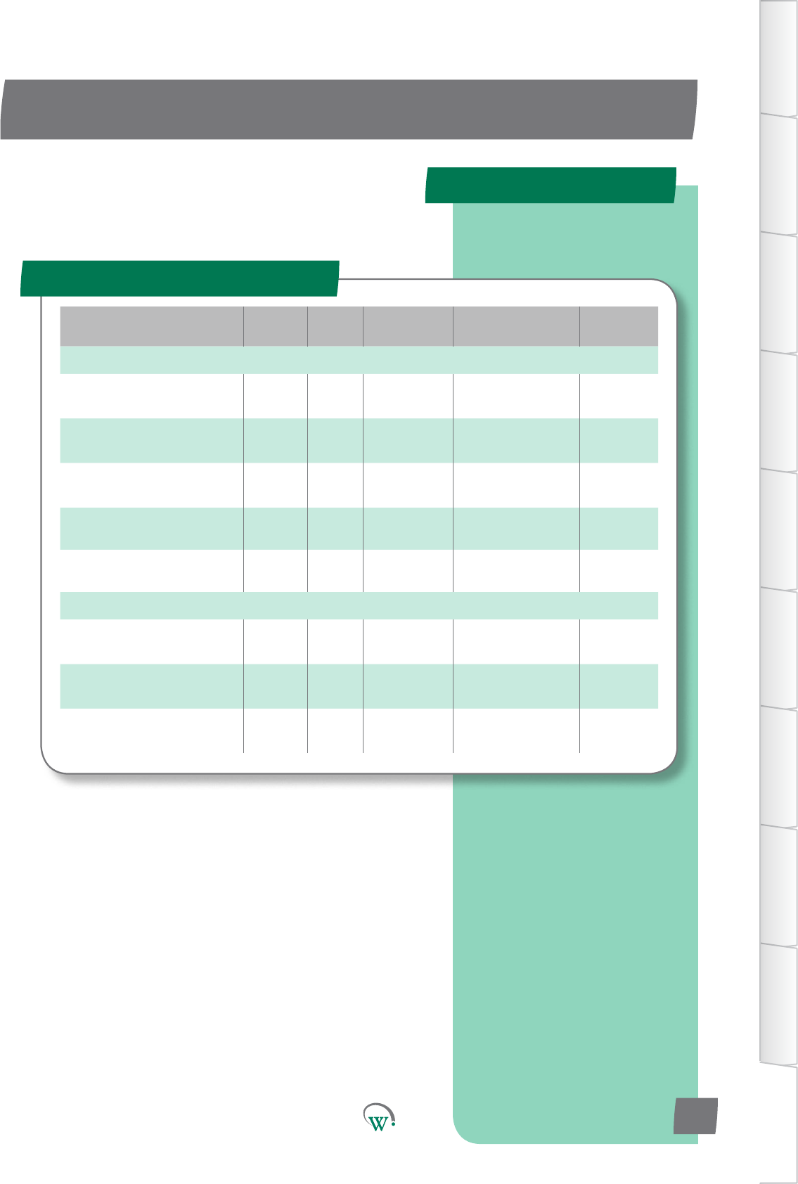
Parameter Name Digital
Display Pages Increments&
Units Range Default
EVAPORATOR
Evaporator Fan Control -
Normal Mode FCn integers 0 - 4 0
Evaporator Fan Setpoint -
Normal Mode FSP 0.1 °C -10 to 15 °C 3.5 °C
EvaporatorFanDIerenal-
Normal Mode Fnd 0.1 °C 0.1 to 10 °C 3 °C
Evaporator Fan Start Delay Fod 1 sec 0 secs 0 secs
Evaporator Fan Stop Delay FSd 1 sec 0 secs 0 secs
ALARMS
HighandLowTemperature
Alarm Delay tdy 1 min 0 to 15 mins 0
HighandLowTemperature
AlarmDierenal tAd 0.1 °C 0.1 °C to 5 °C 1 °C
ProductOutOfSpecicaon
Alarm PCA 1 min dISabled dISabled
Quick Read
APPENDIX 2
Normal - Adv (nrL)
TABLE OF
CONTENTS
INTRODUCTION
& WARNINGS
DESCRIPTION
& INSTALLATION
FRONT PANEL
USER INTERFACE
GRAPHICAL
USER INTERFACE
PARAMETERS
UPGRADING
FIRMWARE
FAULTS &
ALARMS
TECHNICAL
SPECIFICATION
APPENDICES
Advanced parameters
PD0006 V2.0 – 08 Jan 2016 101
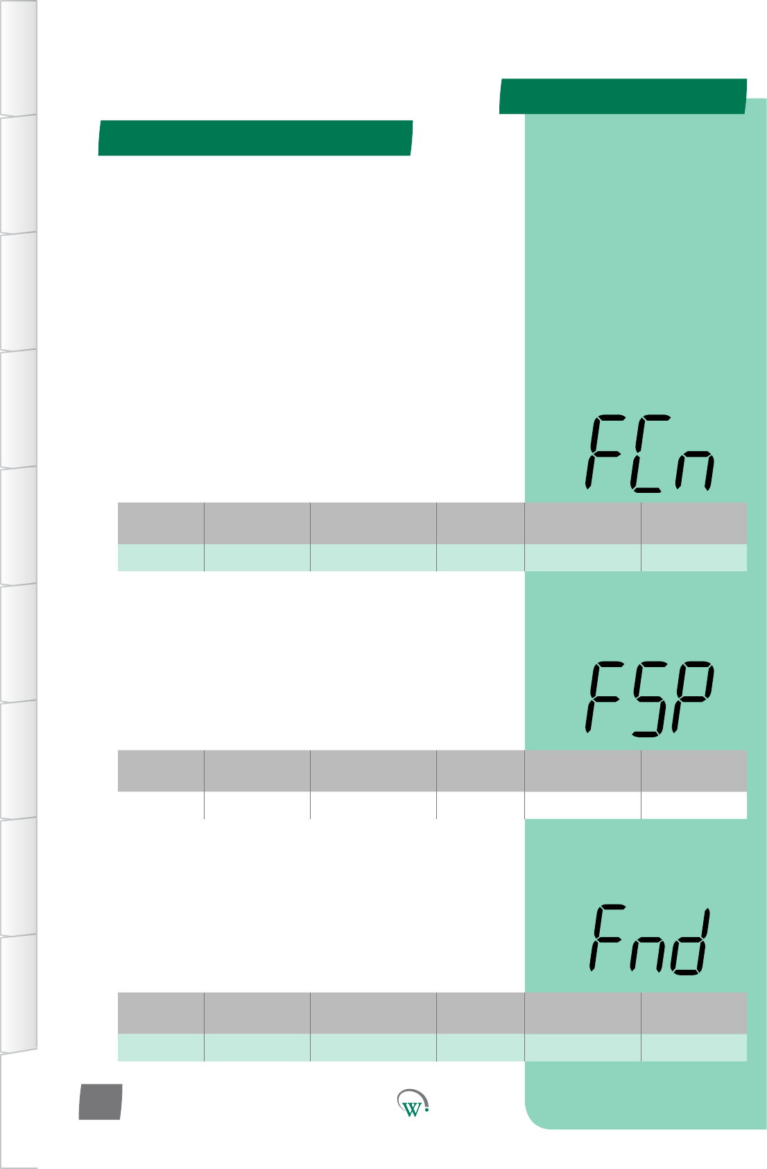
Digital
Display
Funconal
Category ParameterRange Increments
&Units Default Related Menus
FCn Evaporator 0 - 3 integers 0 SP, dIt, SSP
Digital
Display
Funconal
Category ParameterRange Increments
&Units Default Related Menus
FSP Evaporator -10 to 10 °C 1 °C 3.5 °C EFt, FCn
Digital
Display
Funconal
Category ParameterRange Increments
&Units Default Related Menus
Fnd Evaporator 0.1 to 10 °C 1 °C 3 °C FCn
APPENDIX 2
Normal - Adv (nrL) - cont
TABLE OF
CONTENTS
INTRODUCTION
& WARNINGS
DESCRIPTION
& INSTALLATION
FRONT PANEL
USER INTERFACE
GRAPHICAL
USER INTERFACE PARAMETERS UPGRADING
FIRMWARE
FAULTS &
ALARMS
TECHNICAL
SPECIFICATION APPENDICES
PD0006 V2.0 – 08 Jan 2016
102
EVAPORATOR FAN CONTROL - NORMAL MODE (FCn)
Selects how the Evaporator Fan is controlled in Normal Mode:
0 = The Evaporator Fan is on at DEFAULT speed when the
Compressor is on, and cycles at DEFAULT speed with the duty
parameterswhentheCompressoriso.
1 = The Evaporator Fan is on at DEFAULT speed when the
Compressor is on, and cycles at LOW speed with the duty
parameterswhentheCompressoriso.
2=TheEvaporatorFanisonoroatDEFAULTspeeddepending
on the Evaporator Fan temperature. This is independent of the
Compressor state.
3=TheEvaporatorFanisonoroatDEAFULTspeeddepending
on the Evaporator Fan temperature when the Compressor is
ON, and cycles with the duty parameters at DEAFULT speed
when the Compressor is OFF.
4 = The Evaporator fan speed is variably linearly controlled from
Low Speed at the current modes setpoint to Default Speed
atVariable-Evap-Fan-Temp-RangeABOVEthecurrentmodes
setpoint
EVAPORATOR FAN SET POINT (°C) (FSP)
The Set Point Temperature when the Evaporator Fan is in
Temperature Control Mode. This is used to control the
Evaporator Fan by Fan temperature rather than Compressor
cycles or duty cycles. Please also refer to FCn.
NOte:ThisfunconisonlyusedwhentheEvaporatorFanisset
to temperature control in the FCn Menu (1 or 2).
EVAPORATOR FAN DIFFERENTIAL (°C) (Fnd)
ThetemperaturedierenalwhentheEvaporatorFan is
in Temperature Control Mode. This is used to control the
Evaporator Fan by Fan temperature rather than Compressor
cycles or duty cycles. Please also refer to FCn.
Note:ThisfunconisonlyusedwhentheEvaporatorFanisset
to temperature control in the FCn Menu (1 or 2).
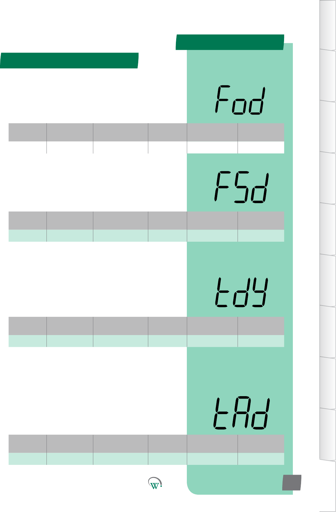
Digital
Display
Funconal
Category ParameterRange Increments
&Units Default Related Menus
FSd Evaporator 0 secs 1 sec 0 secs Fod
Digital
Display
Funconal
Category ParameterRange Increments
&Units Default Related Menus
Fod Evaporator 0 secs 1 sec 0 secs FSd
Digital
Display
Funconal
Category ParameterRange Increments
&Units Default Related Menus
tdy Alarms oFF 1 min oFF SP
Digital
Display
Funconal
Category ParameterRange Increments
&Units Default Related Menus
tAd Alarms 0 °C to 5°C 1 °C 1 °C htA, LtA, tdy
APPENDIX 2
Normal - Adv - cont
TABLE OF
CONTENTS
INTRODUCTION
& WARNINGS
DESCRIPTION
& INSTALLATION
FRONT PANEL
USER INTERFACE
GRAPHICAL
USER INTERFACE
PARAMETERS
UPGRADING
FIRMWARE
FAULTS &
ALARMS
TECHNICAL
SPECIFICATION
APPENDICES
PD0006 V2.0 – 08 Jan 2016 103
* EVAPORATOR FAN STOP DELAY (FSd)
ThemedelaybetweenwhentheCompressorstopsandwhen
the Evaporator Fan is allowed to stop.
* Not yet enabled
* EVAPORATOR FAN START DELAY (Fod)
ThemedelaybetweenwhentheCompressorstartsandwhen
the Evaporator Fan is allowed to start.
* Not yet enabled
*HIGH&LOWTEMPERATURE ALARM DELAY (tdy)
ThemaximumpermiedmethatSetPointTemperatures
canbeexceededbeforetriggeringanalarm.Thismedelay
preventsalarmstriggeringduetomomentarytemperature
spikes.
Thisfunconisdisabledwhensetto‘oFF’.
* Not yet enabled
*HIGH&LOWTEMPERATURE ALARM DIFFERENTIAL (tAd)
ThedierenalbelowtheHighTemperatureAlarmSetPoint
(htA), and above the Low Temperature Alarm Set Point (LtA)
which resets the audible alarm.
Notethatthealarmwillsllbeshownonthedisplayunlitis
acknowledgedbytheuser.
* Associated alarm not yet enabled
APPENDIX 2
Normal - Adv (nrL) - cont
TABLE OF
CONTENTS
INTRODUCTION
& WARNINGS
DESCRIPTION
& INSTALLATION
FRONT PANEL
USER INTERFACE
GRAPHICAL
USER INTERFACE PARAMETERS UPGRADING
FIRMWARE
FAULTS &
ALARMS
TECHNICAL
SPECIFICATION APPENDICES
PD0006 V2.0 – 08 Jan 2016
104
Digital
Display
Funconal
Category ParameterRange Increments
&Units Default Related Menus
PCA Alarms dISabled 1 min dISabled htA, LtA 1
* PRODUCT OUT OF SPECIFICATION ALARM (PCA)
TheduraonoftheaudiblealarmduetotheProductstored
inthecabinetbeingoutoftemperaturespecicaon.Please
alsorefertothehtAandLtAparameterswhichdenethe
temperatureswhichwilltriggerthisaudiblealarm.Ifthe
audiblealarmmesout,thealarmwillsllbeshownonthe
displayunlitisacknowledgedbytheuser.
oFF = Fully disabled alarm. The alarm display and the audible
alarm are both disabled.
0mins=Parallydisabledalarm.Thealarmshowsonthe
display, but is disabled audibly.
Note:evenwhen‘oFF’ischosen,thealarmeventisslllogged
and can be viewed by Service Technicians at a later date.
* Not yet enabled
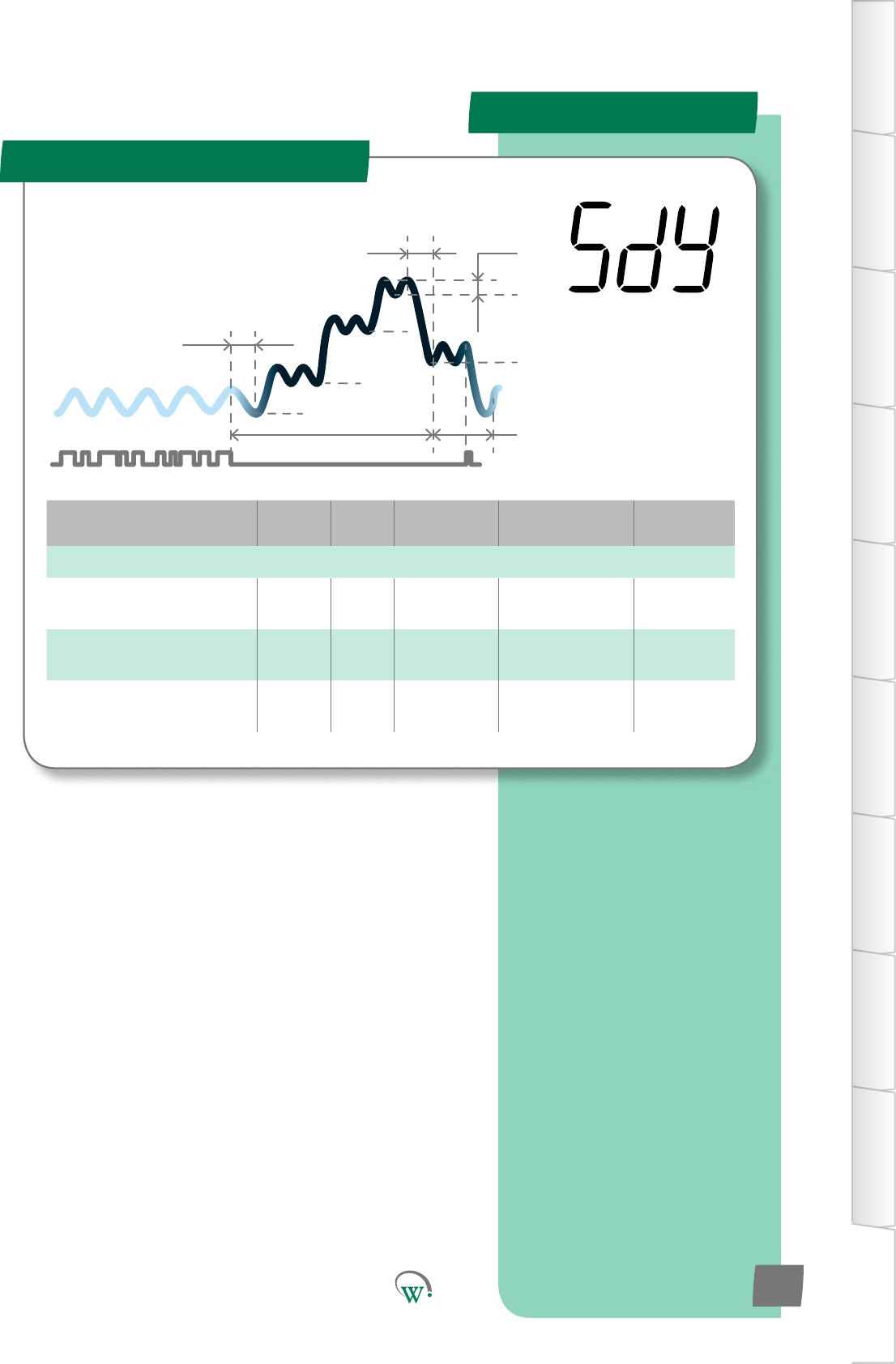
Parameter Name Digital
Display Pages Increments
&Units Range Default
EVAPORATOR
Evaporator Fan Control -
Standby Fby integers 0 - 2 2
Evaporator On Time -
Standby Fts 1min 0 - 30 mins 2 mins
EvaporatorOTime-
Standby Fos 1min 0 - 30 mins 2 mins
APPENDIX 2
Standby - Adv (SdY)
SP
tS1
Sbt
tS2
Ytn
SSP
Sd
Pdt
yt3
tS3
TABLE OF
CONTENTS
INTRODUCTION
& WARNINGS
DESCRIPTION
& INSTALLATION
FRONT PANEL
USER INTERFACE
GRAPHICAL
USER INTERFACE
PARAMETERS
UPGRADING
FIRMWARE
FAULTS &
ALARMS
TECHNICAL
SPECIFICATION
APPENDICES
PD0006 V2.0 – 08 Jan 2016 105
The Standby Modes are an
intelligentmethodtosavepower
whentheCoolersarenotbeing
accessedbycustomers,generally
outside of normal business hours.
The SCS™ Connect can
managethisprocessto
minimizethePulldown
mewhenbusinessesre-
open,oritcanmaximize
energysavingsoverall.
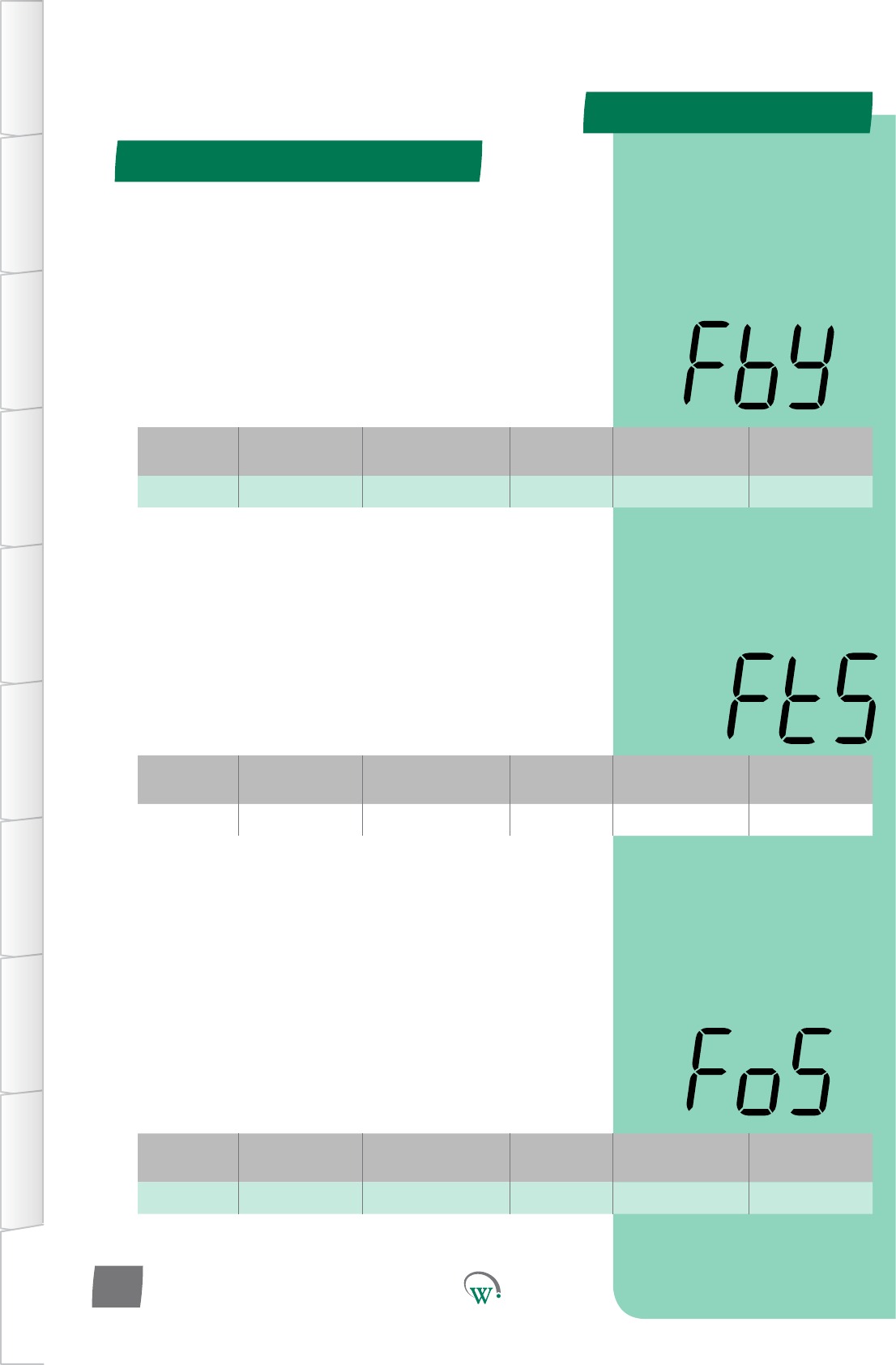
Digital
Display
Funconal
Category ParameterRange Increments
&Units Default Related Menus
Fby Evaporator 0 - 2 integers 2 SSP, FtS
Digital
Display
Funconal
Category ParameterRange Increments
&Units Default Related Menus
FtS Evaporator 1 to 180 secs 1 sec 120 secs FoS
Digital
Display
Funconal
Category ParameterRange Increments
&Units Default Related Menus
FoS Evaporator 0 to 180 secs 1 sec 0 secs FtS
APPENDIX 2
Standby - Adv (SdY) - cont
TABLE OF
CONTENTS
INTRODUCTION
& WARNINGS
DESCRIPTION
& INSTALLATION
FRONT PANEL
USER INTERFACE
GRAPHICAL
USER INTERFACE PARAMETERS UPGRADING
FIRMWARE
FAULTS &
ALARMS
TECHNICAL
SPECIFICATION APPENDICES
PD0006 V2.0 – 08 Jan 2016
106
EVAPORATOR FAN CONTROL - STANDBY MODE (Fby)
ThiscongureshowtheEvaporatorFaniscontrolledwhenthe
SCS™ Connect is in Standby Mode:
0 = The Evaporator Fan is on at LOW speed when the
Compressor is on, and cycles with the NORMAL MODE duty
parametersatLOWspeedwhentheCompressoriso.
1 = The Evaporator Fan is on at LOW speed when the
Compressor is on, and cycles with the STANDBY duty
parametersatLOWspeedwhentheCompressoriso.
2=FollowsALLNormalModesengsandparameters.
EVAPORATOR FAN ON TIME–STANDBY MODE (FtS)
ThelengthofmetheEvaporatorFanisonwhenthe
CompressorisoduringfullStandbyMode.
0=TheEvaporatorFanisalwayso.
Pleasenote:ThetotalEvaporatorFancycle=theonme+the
ome.PleasealsorefertoFoS.
Note:ThisisonlyacvewhenFby=1
EVAPORATOR FAN OFFTIME–STANDBY MODE (FoS)
ThelengthofmetheEvaporatorFanisowhenthe
CompressorisoduringfullStandbyMode.
0 = The Evaporator Fan is always on.
Pleasenote:ThetotalEvaporatorFancycle=theonme+the
ome.PleasealsorefertoFtS.
Note:ThisisonlyacvewhenFby=1
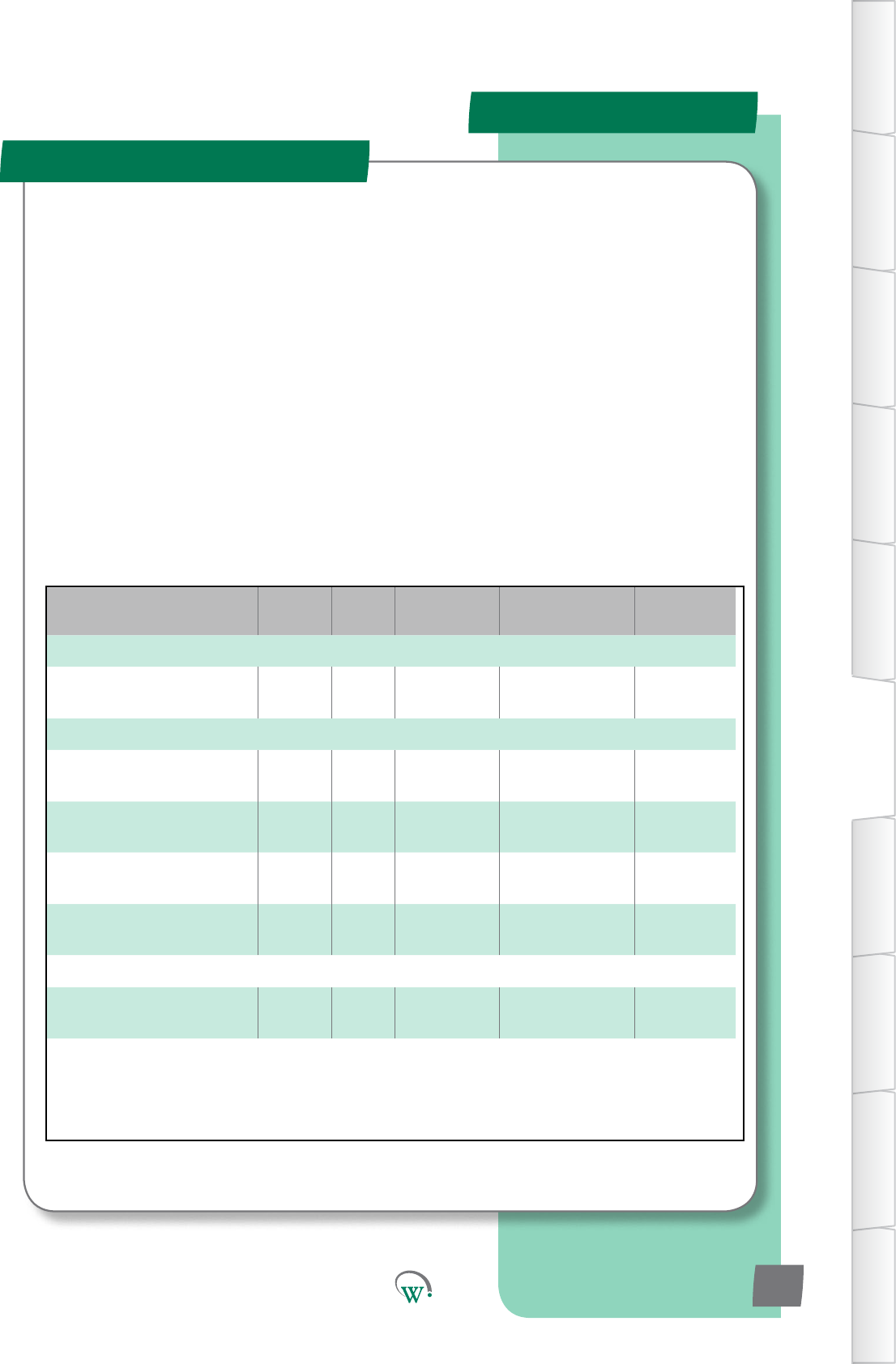
PARAMETERS
TABLE OF
CONTENTS
INTRODUCTION
& WARNINGS
DESCRIPTION
& INSTALLATION
FRONT PANEL
USER INTERFACE
GRAPHICAL
USER INTERFACE
PARAMETERS
UPGRADING
FIRMWARE
FAULTS &
ALARMS
TECHNICAL
SPECIFICATION
APPENDICES
PD0006 V2.0 – 08 Jan 2016 107
Parameter Name Digital
Display Pages Increments
&Units Range Default
TEMPERATURE
Variable Evap Fan
TemperatureRange Etr 106 0.1 °C 5.0 to 50 °C 5.0 °C
SPEED
Variable Evap Fan Speed -
Default ESd 106 10rpm 500 to 2300 1800 rpm
Variable Evap Fan Speed -
Low ESL 106 10rpm 500 to 2300 1300 rpm
Variable Cond Fan Speed -
Default CSd 106 10rpm 500 to 2300 1800 rpm
Variable Cond Fan Speed -
Low CSL 106 10rpm 500 to 2300 1300 rpm
TIME
Variable Cond Fan Reverse
Time CRt 106 1 min 0 to 15 0 mins
Variable Speeds - Adv (???)
TheVariableSpeedsengsareusedtosetdierentspeeds
whenrunninginvariablespeedmode.Iftheevaporatorand
Condensorfanarebothsettoon/omode,theseparameters
havenoeect.
PARAMETERS
TABLE OF
CONTENTS
INTRODUCTION
& WARNINGS
DESCRIPTION
& INSTALLATION
FRONT PANEL
USER INTERFACE
GRAPHICAL
USER INTERFACE PARAMETERS UPGRADING
FIRMWARE
FAULTS &
ALARMS
TECHNICAL
SPECIFICATION APPENDICES
PD0006 V2.0 – 08 Jan 2016
108
Digital
Display
Funconal
Category ParameterRange Increments
&Units Default Related Menus
Etr Temperature 5.0 to 50.0 °C 0.1 °C 5.0 °C
VARIABLE EVAP FAN TEMPERATURE RANGE (Etr)
The temperature ABOVE the current modes setpoint, at which
the evap fan will run at the Variable Evap Fan Speed - Default.
Speed increases linearly with temperature from Variable Evap
Fan Speed - Default when control temperature equals setpoint
temperature
Note:OnlyacvewhenFCn=4
VARIABLE EVAP FAN SPEED - DEFAULT (ESd)
Thespeedusedforallbasicevaporatorfanoperaonwhen
usingaspeedcontrolledmotor.Ifanon-speedcontrolled
motorisbeingused,thisparameterisignored
VARIABLE EVAP FAN SPEED - LOW (ESL)
The speed used as the evaporator fan slower speed if required
basedonconguraon
VARIABLE COND FAN SPEED - DEFAULT (CSd)
Thespeedusedforallbasiccondensorfanoperaon
Digital
Display
Funconal
Category ParameterRange Increments
&Units Default Related Menus
ESd Speed 500 to 2300rpm 10 rpm 1800 rpm
Digital
Display
Funconal
Category ParameterRange Increments
&Units Default Related Menus
ESL Speed 500 to 2300rpm 10 rpm 1300 rpm
Digital
Display
Funconal
Category ParameterRange Increments
&Units Default Related Menus
CSd Speed 500 to 2300rpm 10 rpm 1800 rpm
Variable Speeds - Adv (???) - cont
PARAMETERS
TABLE OF
CONTENTS
INTRODUCTION
& WARNINGS
DESCRIPTION
& INSTALLATION
FRONT PANEL
USER INTERFACE
GRAPHICAL
USER INTERFACE
PARAMETERS
UPGRADING
FIRMWARE
FAULTS &
ALARMS
TECHNICAL
SPECIFICATION
APPENDICES
PD0006 V2.0 – 08 Jan 2016 109
VARIABLE COND FAN SPEED - LOW (CSL)
The speed used as the condensor fan slower speed if required
basedonconguraon
VARIABLE COND FAN REVERSE TIME (Crt)
Themewhichthecondensorfanwillruninreverseatthe
lowspeed,beforestopping,aerthecompressorhasjustbeen
turnedo.Onlyacvewithaspeedcontrolledmotor.Ifanon-
speedcontrolledmotorisbeingused,thisparameterisignored
Digital
Display
Funconal
Category ParameterRange Increments
&Units Default Related Menus
CSL Speed 500 to 2300rpm 10 rpm 1300 rpm
Digital
Display
Funconal
Category ParameterRange Increments
&Units Default Related Menus
Crt Time 0 to 15 mins 1 min 0 mins
Variable Speeds - Adv (???) - cont
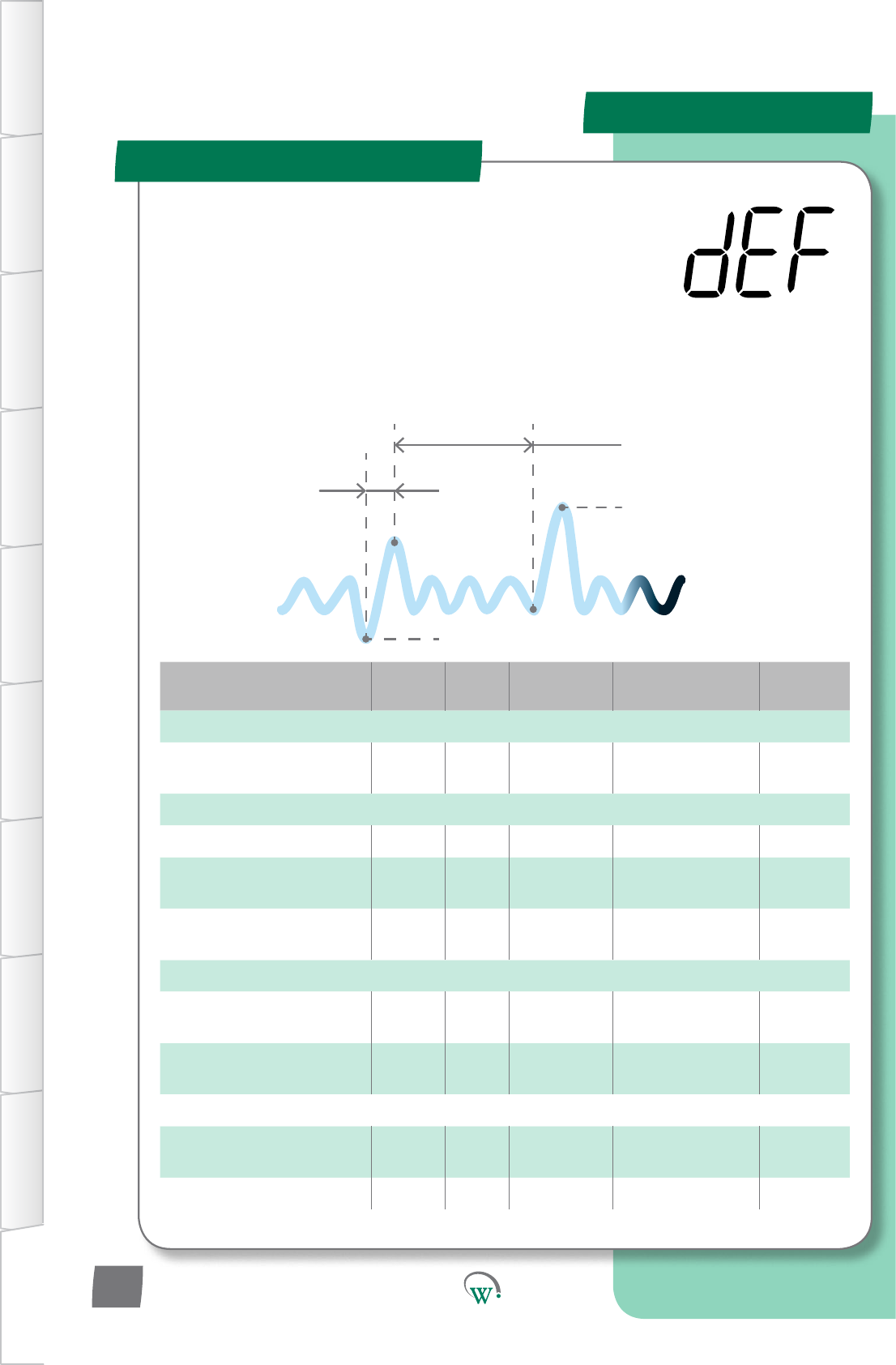
Parameter Name Digital
Display Pages Increments
&Units Range Default
TEMPERATURE
FreezeUpProtecon
Temperature FPt 1 °C dISabled dISabled
TIME
DefrostIniaonDelay ddy 1 sec 0 secs 0 secs
Defrost Relay Output On
Time Delay dod 1 sec 0 secs 0 secs
No Downwards Tendency
Defrost Time ndt 1 hr dISabled dISabled
LIGHTING & DISPLAY
Temperature Display Lock
TimeAerDefrost tdL 1 min 0 mins 0 mins
ForceLightsOnDuring
Defrost Lod n/a no no
ALARMS
DefrostTerminaonby
Alarm Count dtA 1 count dISabled dISabled
FreezeUpProteconDelay FPd 1 min 0 mins 0
APPENDIX 2
Defrost - Adv (dEF)
DefrostIniaonTemperature(dIt)
Defrost Cycle
Time (dCt)
Maximum
Defrost
Interval (dEI)
DefrostTerminaon
Temperature(d)
TABLE OF
CONTENTS
INTRODUCTION
& WARNINGS
DESCRIPTION
& INSTALLATION
FRONT PANEL
USER INTERFACE
GRAPHICAL
USER INTERFACE PARAMETERS UPGRADING
FIRMWARE
FAULTS &
ALARMS
TECHNICAL
SPECIFICATION APPENDICES
PD0006 V2.0 – 08 Jan 2016
110
TheDefrostCyclecanbeiniatedorterminatedbyeither
meortemperature.DuringtheDefrostCycletheNormal
OperaonalModeisoverriddentocontroltheCompressor,
EvaporatorFan,Lights,andifused,anyvalvesorheater
elements connected to the 5A Relay.
SupportedDefrostCyclemethodsare;hotgasdefrost(reverse
cycle),ambientdefrost(withthecompressorturnedo),and
a forced defrost (with an electric heater element).
Theseparametersprovidetheoponstocontroland
conguretheDefrostCycle.
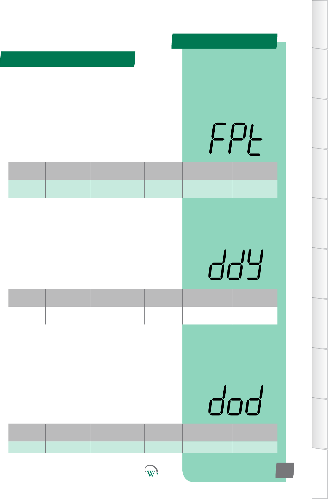
Digital
Display
Funconal
Category ParameterRange Increments
&Units Default Related Menus
FPt Temperature dISabled 1 °C dISabled dli,d
Digital
Display
Funconal
Category ParameterRange Increments
&Units Default Related Menus
dod Time 0 secs 1 sec 0 secs dtP, dFS
Digital
Display
Funconal
Category ParameterRange Increments
&Units Default Related Menus
ddy Time 0 secs 1 sec 0 secs dIt
APPENDIX 2
Defrost - Adv (dEF) - cont
TABLE OF
CONTENTS
INTRODUCTION
& WARNINGS
DESCRIPTION
& INSTALLATION
FRONT PANEL
USER INTERFACE
GRAPHICAL
USER INTERFACE
PARAMETERS
UPGRADING
FIRMWARE
FAULTS &
ALARMS
TECHNICAL
SPECIFICATION
APPENDICES
PD0006 V2.0 – 08 Jan 2016 111
* DEFROST INITIATION DELAY (ddy)
ThemethecontroltemperaturemustbebelowtheDefrost
IniaonTemperature(dIt)beforeDefrostwillbeacvated.
Please note: If the control temperature rises above the Defrost
IniaonTemperature(dIt),theDefrostIniaonDelay(ddy)
counter will be reset.
* Not yet enabled
* DEFROST RELAY OUTPUT ON TIME DELAY (dod)
Themeneededtobuildupsucienthotgasforahotgas
typedefrost.ThisfunconisonlyusedforhotgastypeDefrost
Cycles.ItisdenedastheamountofmetheCompressor
keepsrunningaeraDefrostCycleistriggered,whilethe
DefrostCycleRelayremainso.Aerthismehaselapsedthe
CompressorturnsoandtheDefrostCycleRelayturnson.This
parameter is only used when dtP is set to 2.
* Not yet enabled
* FREEZE UP PROTECTION TEMPERATURE (FPt)
The Evaporator Coil temperature below which the Compressor
willturnoandtheEvaporatorFanwillturnon.Thisisto
providesmartfreezeupproteconoftheevapcoil.Evaporator
Fanon/omerswillbesuspendedunlthetemperaturehas
risenabovetheFreeze-upprotecontemperature,andnormal
control has resumed.
Note: Only applicable when Evaporator Fan Coil sensor is
allocated
* Not yet enabled
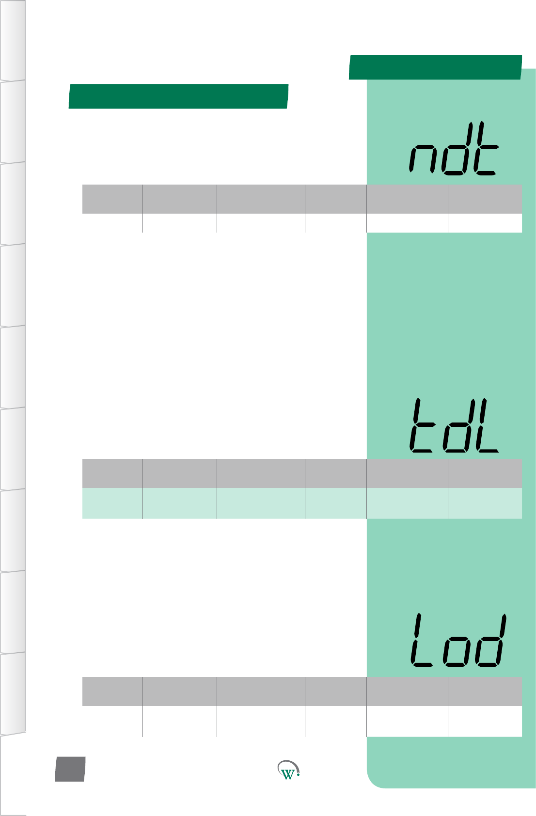
Digital
Display
Funconal
Category ParameterRange Increments
&Units Default Related Menus
Lod Lighng&
Display no n/a no LSy
Digital
Display
Funconal
Category ParameterRange Increments
&Units Default Related Menus
tdL Lighng&
Display 0 mins 1 min 0 mins ddE, dIS, SP
Digital
Display
Funconal
Category ParameterRange Increments
&Units Default Related Menus
ndt Time dISabled 1 sec 0 secs dtP, dFS
APPENDIX 2
Defrost - Adv (dEF) - cont
TABLE OF
CONTENTS
INTRODUCTION
& WARNINGS
DESCRIPTION
& INSTALLATION
FRONT PANEL
USER INTERFACE
GRAPHICAL
USER INTERFACE PARAMETERS UPGRADING
FIRMWARE
FAULTS &
ALARMS
TECHNICAL
SPECIFICATION APPENDICES
PD0006 V2.0 – 08 Jan 2016
112
* TEMPERATURE DISPLAY LOCK TIME AFTER DEFROST (tdL)
Themethedisplaywillconnuetoshowthevalueas
denedbyDisplayValueDuringDefrostCycle(ddE)once
theDefrostCyclehasnished.Thisdelayallowstheinternal
cabinettemperaturetore-stabilizebeforedisplayingthe
actual temperature. If the cabinet temperature reaches the
OperaonalSetPointTemperature(SP)beforetheLockTime
(tdL) has elapsed, the display will revert to Normal Display
Mode (dIS).
* Not yet enabled
* FORCE LIGHTS ON DURING DEFROST (Lod)
ForcesthecabinetlightstocomeonduringaDefrost,should
thelightsbeturnedo.Thishelpswarmupthecabinet.This
funconisofmostusewhenuorescentlampsareed.
* Not yet enabled
* NO DOWNWARDS TENDENCY DEFROST TIME (ndt)
Themeallowedwhilethecompressorisonwithoutthe
temperaturereducing,beforeadefrostcycleisforced.
* Not yet enabled
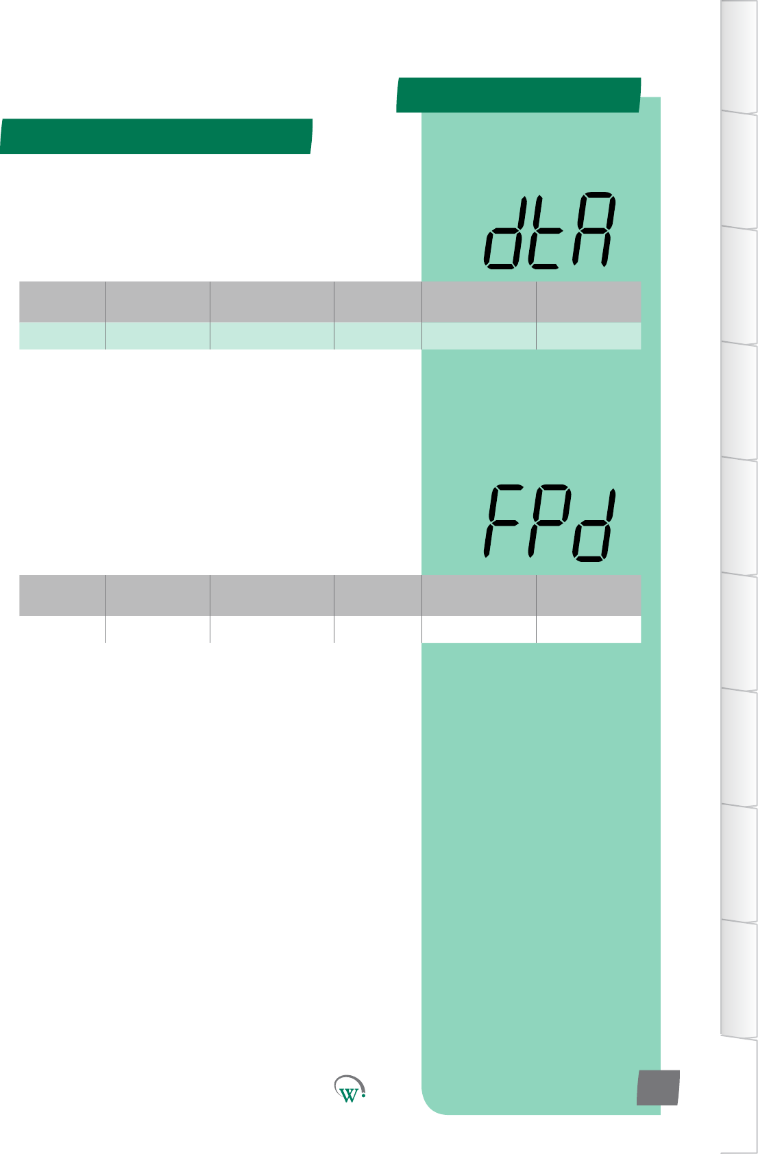
Digital
Display
Funconal
Category ParameterRange Increments
&Units Default Related Menus
dtA Alarms dISabled 1 count dISabled
Digital
Display
Funconal
Category ParameterRange Increments
&Units Default Related Menus
FPd Alarms 0 mins 1 min 0
APPENDIX 2
TABLE OF
CONTENTS
INTRODUCTION
& WARNINGS
DESCRIPTION
& INSTALLATION
FRONT PANEL
USER INTERFACE
GRAPHICAL
USER INTERFACE
PARAMETERS
UPGRADING
FIRMWARE
FAULTS &
ALARMS
TECHNICAL
SPECIFICATION
APPENDICES
PD0006 V2.0 – 08 Jan 2016 113
* DEFROST TERMINATION BY TIME ALARM COUNT (dtA)
Thenumberofdefrostterminaonbymeinstancesthat
canoccurbeforeanalarmistriggered.Usedwheredefrost
terminaonbytemperatureistheexpectednorm.
* Not yet enabled
* FREEZE UP PROTECTION DELAY (FPd)
Temperaturebelowwhichthecompressorwillturnoandthe
evaporatorfanwillturnon,overidinganyothersengs.Thisis
topreventtehevaporatorcoilsfromfreezingupinthecaseofa
low temperature overshoot.
* Not yet enabled
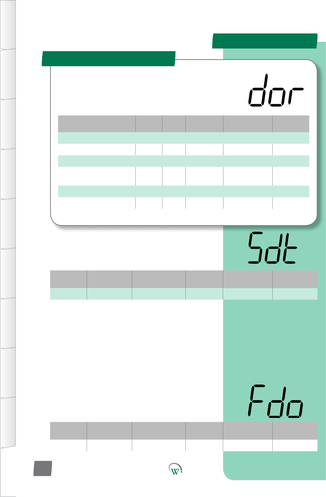
Parameter Name Digital
Display Pages Increments
&Units Range Default
TEMPERATURE
Sensorless Door Threshold sdt 0.01 °C 0 .10°C to 1.00 °C 0.5 °C
EVAPORATOR
Evaporator Fan Control
When Door Open Fdo integer 0 - 3 0
TIME
Door Switch Fail Delay dFd 1 min 5 mins to 15 mins 10 mins
Digital
Display
Funconal
Category ParameterRange Increments
&Units Default Related Menus
sdt Temperature 0.10 °C to 1.00 °C 0.01 °C 5.00 °C
SENSORLESS DOOR THRESHOLD (sdt)
Thesensivitytoatemperaturechangefordetermininga
sensorlessdooropening.
Digital
Display
Funconal
Category ParameterRange Increments
&Units Default Related Menus
Fdo Evaporator on or oFF text oFF Fby, FCn
APPENDIX 2
Door - Adv (dor)
TABLE OF
CONTENTS
INTRODUCTION
& WARNINGS
DESCRIPTION
& INSTALLATION
FRONT PANEL
USER INTERFACE
GRAPHICAL
USER INTERFACE PARAMETERS UPGRADING
FIRMWARE
FAULTS &
ALARMS
TECHNICAL
SPECIFICATION APPENDICES
PD0006 V2.0 – 08 Jan 2016
114
The SCS™ Connect uses the cabinet door switch as an input
devicetohelpcontroltheEvaporatorFan,Lightsandto
iniateAlarms.Pleasenote:Shouldthedoorswitchfail,these
parameterswillnotfunconcorrectly.
EVAPORATOR FAN CONTROL WHEN CABINET DOOR OPEN (Fdo)
Selects how the Evaporator Fan is controlled when the door is
open.Thisistoallowthefantoconnuouslyrun,whichcanbe
benecialbymaintaininganaircurtain.
0=TheEvaporatorFanisturnedowhilethedoorisopen.
1 = The Evaporator Fan is turned on at DEAFULT speed while
the door is open.
2 = The Evaporator Fan is turned on at LOW speed while the
door is open.
3 = The Evaporator Fan is controlled as if the door was not
open.

Digital
Display
Funconal
Category ParameterRange Increments
&Units Default Related Menus
dFd Time 5 mins to 15 mins 1 min 10 mins
DOOR SWITCH FAIL DELAY (dFd)
Themeaeradoorisseenasopen,beforethesystem
determinestehdoorswitchhasfailed.Aerthsme,the
systemwillignorethedoorswitchandrunnormally,unla
doorclosedstateisseen,whichresetsthemer.
APPENDIX 2
Door - Adv (dor) - cont
TABLE OF
CONTENTS
INTRODUCTION
& WARNINGS
DESCRIPTION
& INSTALLATION
FRONT PANEL
USER INTERFACE
GRAPHICAL
USER INTERFACE
PARAMETERS
UPGRADING
FIRMWARE
FAULTS &
ALARMS
TECHNICAL
SPECIFICATION
APPENDICES
PD0006 V2.0 – 08 Jan 2016 115
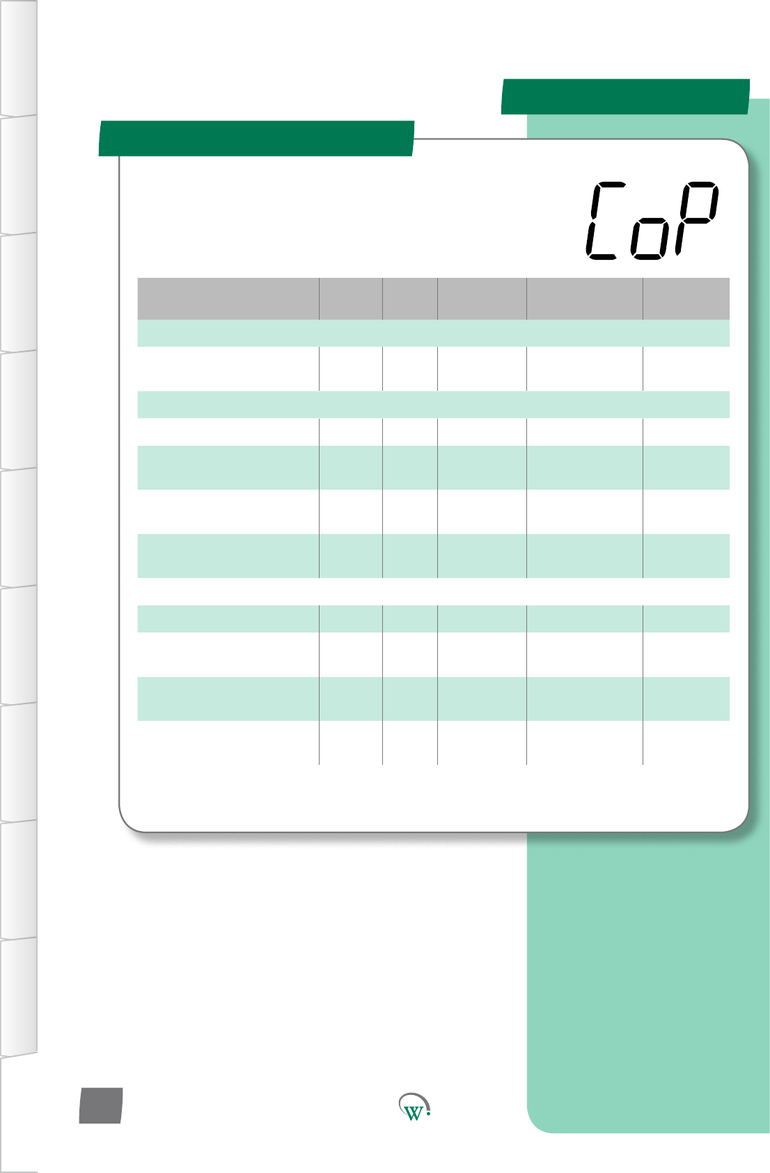
Parameter Name Digital
Display Pages Increments
&Units Range Default
TEMPERATURE
Return Air Under Temp
Dierenal rud 0.1 °C 0.1 °C to 15.0 °C 3 °C
TIME
Minimum Run Time rnt 10 sec 0secs 0 secs
Sensor Failure Compressor
Override Time SCt 1 hour dISabled dISabled
Sensor Failure Compressor
OTime SCo 1 min 1 to 60 mins 30 mins
Sensor Failure Compressor
On Time SCr 1 min 1 to 60 mins 10 mins
ALARMS
HighTemperatureDelay htd 1 sec 10 secs 10 secs
HighTemperature
Dierenal htF 1 °C 20 °C 20 °C
HighTemperatureLockout
Count htC counts dISabled dISabled
CondenserHigh
Temperature Alarm ChA 1 min dISabled dISabled
APPENDIX 2
Compressor - Adv (CoP)
TABLE OF
CONTENTS
INTRODUCTION
& WARNINGS
DESCRIPTION
& INSTALLATION
FRONT PANEL
USER INTERFACE
GRAPHICAL
USER INTERFACE PARAMETERS UPGRADING
FIRMWARE
FAULTS &
ALARMS
TECHNICAL
SPECIFICATION APPENDICES
PD0006 V2.0 – 08 Jan 2016
116
Theseparametersprovideoponstocontrolandcongure
theCompressorduringdierentpartsoftherefrigeraon
cycleandtoconguretheCompressorAlarms.
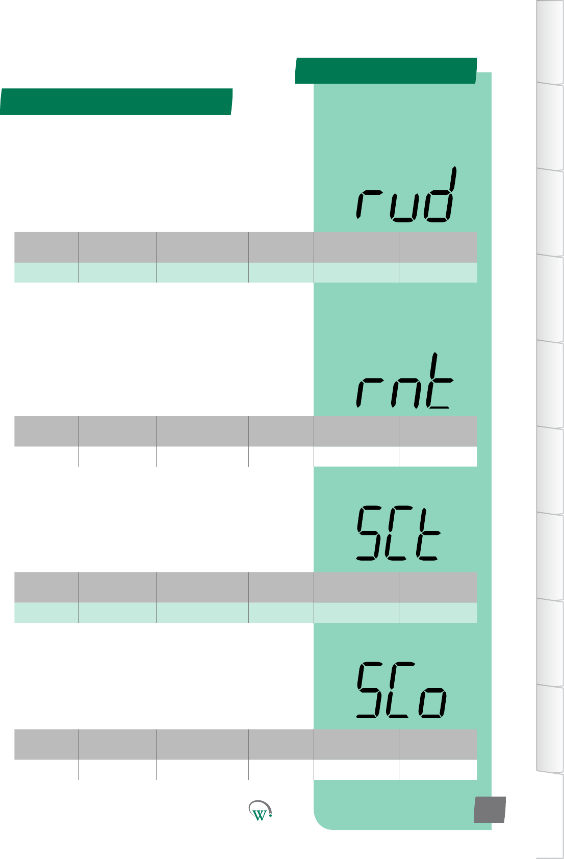
Digital
Display
Funconal
Category ParameterRange Increments
&Units Default Related Menus
rud Temperatue 0.1 °C to 15.0 °C 0.1 °C 3 °C
Digital
Display
Funconal
Category ParameterRange Increments
&Units Default Related Menus
SCt Time dISabled 1 hour dISabled
Digital
Display
Funconal
Category ParameterRange Increments
&Units Default Related Menus
SCo Time 1 to 60 mins 1 min 30 mins
Digital
Display
Funconal
Category ParameterRange Increments
&Units Default Related Menus
rnt Time 0 secs 10 secs 0 secs Pod, Cot
APPENDIX 2
Compressor - Adv (CoP) - cont
TABLE OF
CONTENTS
INTRODUCTION
& WARNINGS
DESCRIPTION
& INSTALLATION
FRONT PANEL
USER INTERFACE
GRAPHICAL
USER INTERFACE
PARAMETERS
UPGRADING
FIRMWARE
FAULTS &
ALARMS
TECHNICAL
SPECIFICATION
APPENDICES
PD0006 V2.0 – 08 Jan 2016 117
RETURN AIR UNDER TEMP DIFFERENTIUAL (rud)
The temperature below the normal mode setpoint at which all
outputswillbeturnedo.Thisistocompensateforincorrect
wiring,wherethecompressormaybewiredtoadierent
output,resulnginconnuouscompressorrunning,even
thoughthecontrollerthinksthecompressoriso.Normal
operaonwillresumeoncethesetpoint+dierenalofthe
current mode is reached.
* SENSOR FAILURE COMPRESSOR OVERIDE TIME (SCt)
Timeaerthecontroltemperaturesensorhasfailed,inwhich
thecompressorwillrunusingtheON/OFFmes,beforethe
compressor will shut down.
* Not yet enabled
* SENSOR FAILURE COMPRESSOR OFF TIME(SCo)
TheOFFdutymeofthecompressor,whenthecontrol
temperature probe has failed
*Funconalitynotyetenabled(SeeSCt)
* MINIMUM RUN TIME (rnt)
TheminimummethattheCompressorwillrun,unless
aprotecvecontrollimitstopsit.Thisfunconisusedto
reduce the number of Compressor starts per hour to improve
eciency.
* Not yet adjustable

Digital
Display
Funconal
Category ParameterRange Increments
&Units Default Related Menus
EEC Outputs N.C. Port ID N.C.
APPENDIX 2
Hardware - Adv (dSP) - cont
TABLE OF
CONTENTS
INTRODUCTION
& WARNINGS
DESCRIPTION
& INSTALLATION
FRONT PANEL
USER INTERFACE
GRAPHICAL
USER INTERFACE PARAMETERS UPGRADING
FIRMWARE
FAULTS &
ALARMS
TECHNICAL
SPECIFICATION APPENDICES
PD0006 V2.0 – 08 Jan 2016
118
ELECTRONIC EXPANSION VALVE PORT CONFIGURATION (EEC)
Selects the Electronic Expansion Valve Port.
N.C. = Not Connected
DSO*=DigitalSwitchedOutput:
AD5=Digital0–5Vi/p,AnalogNTCi/p,5V300mAo/p
LE1–LE3=PWM0V2ADCperchannel
* Not yet enabled
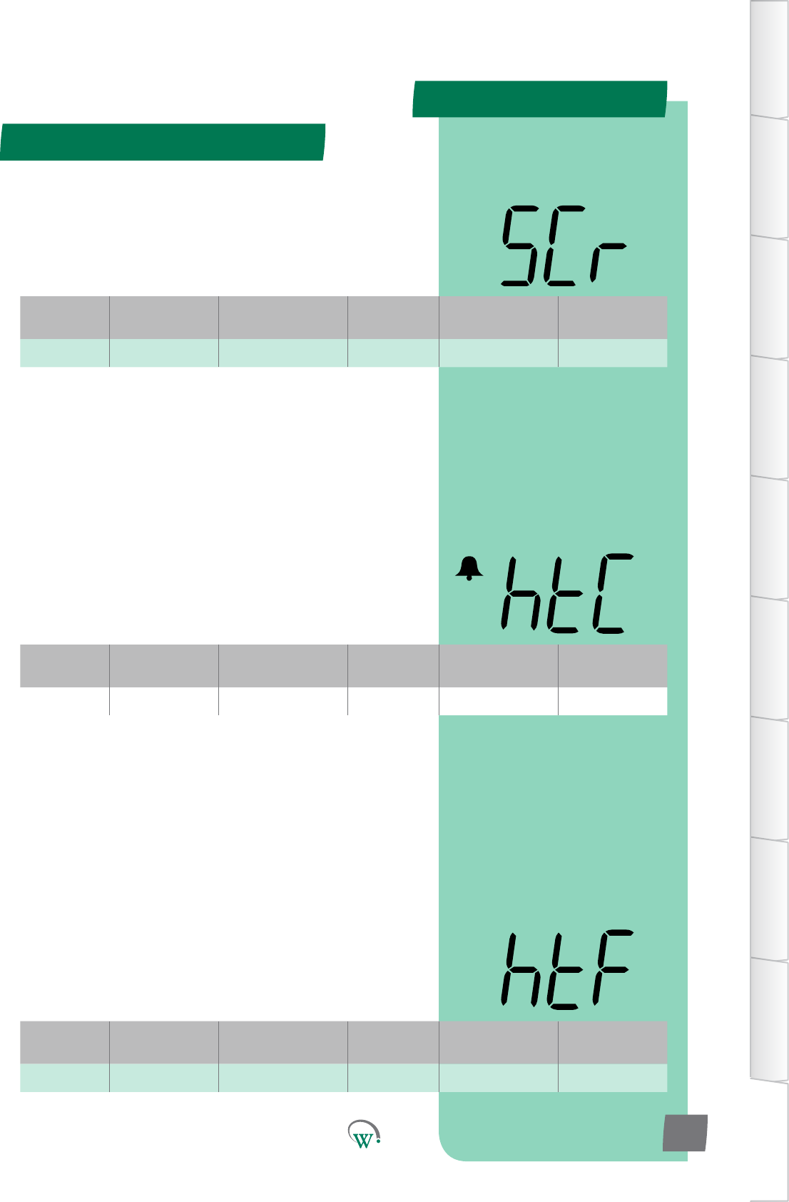
Digital
Display
Funconal
Category ParameterRange Increments
&Units Default Related Menus
SCr Time 1 to 60 mins 1 min 10 mins
Digital
Display
Funconal
Category ParameterRange Increments
&Units Default Related Menus
htC Alarms dISabled singlecounts dISabled ASP
Digital
Display
Funconal
Category ParameterRange Increments
&Units Default Related Menus
htF Alarms 20 °C 1 °C 20 °C htA, htr
Compressor - Adv (CoP) - cont
APPENDIX 2
TABLE OF
CONTENTS
INTRODUCTION
& WARNINGS
DESCRIPTION
& INSTALLATION
FRONT PANEL
USER INTERFACE
GRAPHICAL
USER INTERFACE
PARAMETERS
UPGRADING
FIRMWARE
FAULTS &
ALARMS
TECHNICAL
SPECIFICATION
APPENDICES
PD0006 V2.0 – 08 Jan 2016 119
* HIGH TEMPERATURE DIFFERENTIAL (htF)
ThetemperaturebelowtheCondenserHighTemperature
Limit (hCt), which will allow the Compressor to turn back on
aeraCondensorHighTemperatureLimit(hCt)event.The
temperaturemustremainbelowthislevelforthemeperiod
denedinHighTemperatureResetDelay(htr)beforethe
Compressor will turn back on.
* Not yet adjustable
* HIGH TEMPERATURE LOCK OUT COUNT (htC)
ThenumberofmesthattheCondensercanexceedthe
CondenserHighTemperatureLimit(hCt)beforeitislockedout
topreventdamage.ImportantNote:Thisprotecvefuncon
cannotberesetbypowercyclingthecabinetonando;itcan
onlyberesetbyanauthorizedServiceTechnician.
* Not yet enabled
* SENSOR FAILURE COMPRESSOR ON TIME (SCr)
TheONdutymeofthecompressorwhenthecontrol
temperature probe has failed
*Funconalitynotyetenabled(SeeSCt)
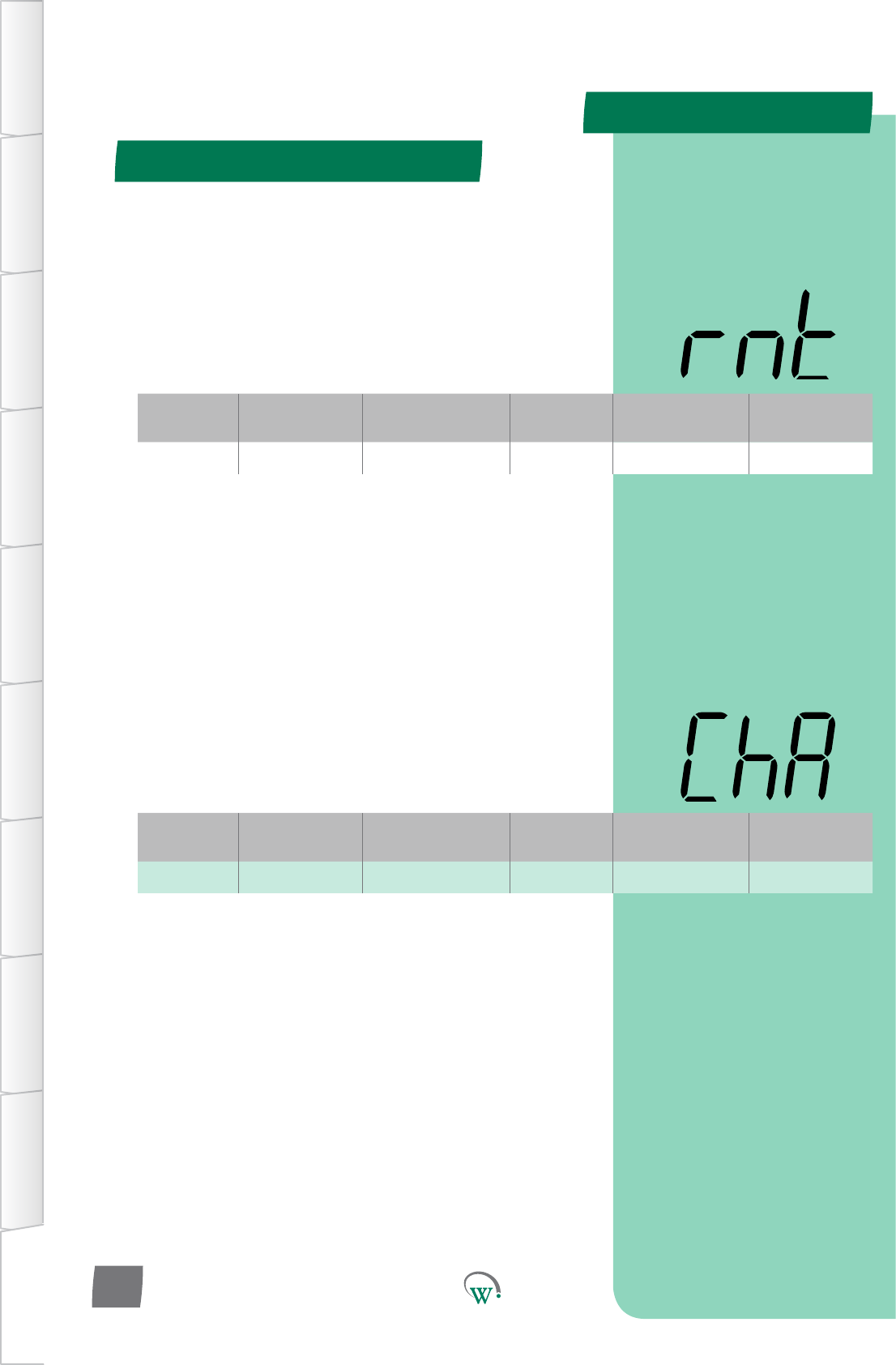
Digital
Display
Funconal
Category ParameterRange Increments
&Units Default Related Menus
htC Alarms dISabled singlecounts dISabled ASP
Digital
Display
Funconal
Category ParameterRange Increments
&Units Default Related Menus
ChA Alarms dISabled 1 min dISabled Cht
Compressor - Adv (CoP) - cont
APPENDIX 2
TABLE OF
CONTENTS
INTRODUCTION
& WARNINGS
DESCRIPTION
& INSTALLATION
FRONT PANEL
USER INTERFACE
GRAPHICAL
USER INTERFACE PARAMETERS UPGRADING
FIRMWARE
FAULTS &
ALARMS
TECHNICAL
SPECIFICATION APPENDICES
PD0006 V2.0 – 08 Jan 2016
120
* HIGH TEMPERATURE LOCK OUT COUNT (htC)
ThenumberofmesthattheCondensercanexceedthe
CondenserHighTemperatureLimit(hCt)beforeitislockedout
topreventdamage.ImportantNote:Thisprotecvefuncon
cannotberesetbypowercyclingthecabinetonando;itcan
onlyberesetbyanauthorizedServiceTechnician.
* Not yet enabled
* CONDENSER HIGH TEMPERATURE ALARM (ChA)
TheduraonoftheaudiblealarmduetotheCondenser
Temperaturebeingconnuouslyabovenormaloperang
temperature.PleaserefertotheCondenserHighTemperature
Limit (Cht) parameter.
oFF = Fully disabled alarm. The alarm display and the audible
alarm are both disabled.
0mins=Parallydisabledalarm.Thealarmshowsonthe
display, but is disabled audibly.
Note:evenwhen‘oFF’ischosen,thealarmeventisslllogged
and can be viewed by Service Technicians at a later date.
* Not yet enabled
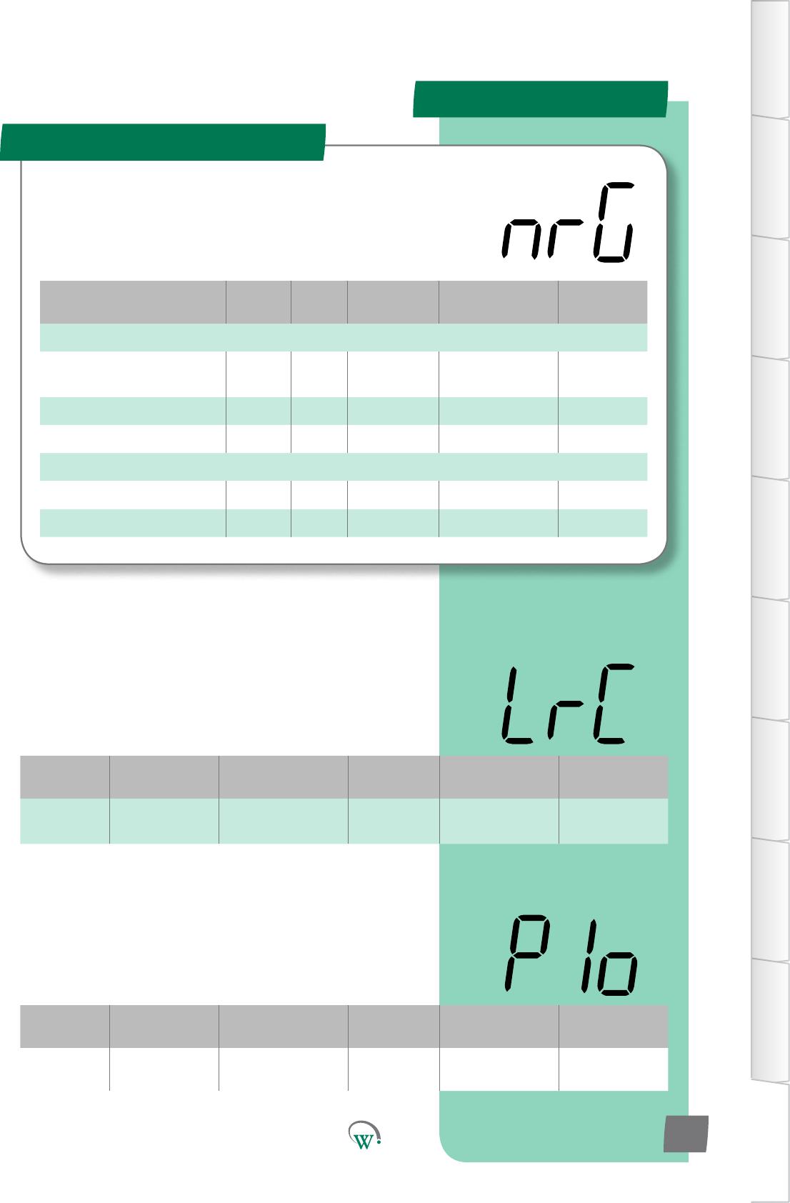
Parameter Name Digital
Display Pages Increments
&Units Range Default
SUPPLY
Minimum Run Compressor
Voltage LrC 1 V 79 V to 203 V
or dISabled 80 V
VoltageCut-In/OutDelay Plo 1 sec 10 secs 10 secs
OutOfVoltageCountLimit oPC counts dISabled dISabled
ALARMS
DuraonHighVoltageAlarm dhA 1 min 0 mins 0 mins
DuraonLowVoltageAlarm dLA 1 min 0 mins 0 mins
Digital
Display
Funconal
Category ParameterRange Increments
&Units Default Related Menus
LrC Supply 79 to 203 V
or dISabled 1 V 80 V hPC, oPt, LPC
Digital
Display
Funconal
Category ParameterRange Increments
&Units Default Related Menus
PIo Supply 0 to 20 secs 1 sec 10 secs hPC, LPC, LrC
APPENDIX 2
Supply - Adv (nrG)
TABLE OF
CONTENTS
INTRODUCTION
& WARNINGS
DESCRIPTION
& INSTALLATION
FRONT PANEL
USER INTERFACE
GRAPHICAL
USER INTERFACE
PARAMETERS
UPGRADING
FIRMWARE
FAULTS &
ALARMS
TECHNICAL
SPECIFICATION
APPENDICES
PD0006 V2.0 – 08 Jan 2016 121
TheSupplyParametersareusedtoconguretheacceptable
limitsfortheVoltagesupplyandtoconguretheassociated
alarms.Thisisrequiredtoprotecttherefrigeraonsystem
fromelectricaldamage.
MINIMUM RUN COMPRESSOR VOLTAGE (LrC)
TheminimumVoltageduringwhichtheCompressorisallowed
toconnuetorun.IfitisbelowthisVoltagetheCompressor
cannotrunandturnso.IftheVoltagerisestoanacceptable
levelthentheCompressorcanrestart,butonlyaerthe
Voltagehasbeenmaintainedforadelayperiod.Theseevents
areloggedintheSCS™Connect.
oFF=RunVoltageequalsStartVoltage.
* VOLTAGE CUT-IN/OUT DELAY (PIo)
ThemethatthepowersupplymustexceedtheOverVoltage
orUnderVoltagecondions,beforedevicesareturnedo.The
purposeofthismedelayistoallowformomentaryspikesin
the power supply.
* Not yet adjustable

Digital
Display
Funconal
Category ParameterRange Increments
&Units Default Related Menus
dhA Alarms 0 mins 1 min 0 mins hPC
Digital
Display
Funconal
Category ParameterRange Increments
&Units Default Related Menus
oPC Supply dISabled singlecounts dISabled hPC, LPC, LrC
Digital
Display
Funconal
Category ParameterRange Increments
&Units Default Related Menus
dLA Alarms 0 mins 1 min 0 mins LPC, LrC
Supply - Adv (nrG) - cont
APPENDIX 2
TABLE OF
CONTENTS
INTRODUCTION
& WARNINGS
DESCRIPTION
& INSTALLATION
FRONT PANEL
USER INTERFACE
GRAPHICAL
USER INTERFACE PARAMETERS UPGRADING
FIRMWARE
FAULTS &
ALARMS
TECHNICAL
SPECIFICATION APPENDICES
PD0006 V2.0 – 08 Jan 2016
122
* OUT OF VOLTAGE COUNT LIMIT (oPC)
ThenumberofOverVoltageorUnderVoltageinstances
permiedina24hourperiodbeforeanalarmistriggered.
Selecng‘0’asthecountnumberwillcauseanalarmtotrigger
on every event.
* Not yet enabled
* DURATION HIGH VOLTAGE ALARM (dhA)
TheduraonoftheaudiblealarmduetoexcessiveHigh
Voltage.PleasealsorefertotheMaximumRun/StartVoltage
(hPC).
oFF = Fully disabled alarm. The alarm display and the audible
alarm are both disabled.
0mins=Parallydisabledalarm.Thealarmshowsonthe
display, but is disabled audibly.
Note:evenwhen‘oFF’ischosen,thealarmeventisslllogged
and can be viewed by Service Technicians at a later date.
* Not yet adjustable
* DURATION LOW VOLTAGE ALARM (dLA)
TheduraonoftheaudiblealarmduetoUnderVoltage.Please
also refer to the LPC and LrC parameters.
oFF = Fully disabled alarm. The alarm display and the audible
alarm are both disabled.
0mins=Parallydisabledalarm.Thealarmshowsonthe
display, but is disabled audibly.
Note:evenwhen‘oFF’ischosen,thealarmeventisslllogged
and can be viewed by Service Technicians at a later date.
* Not yet adjustable
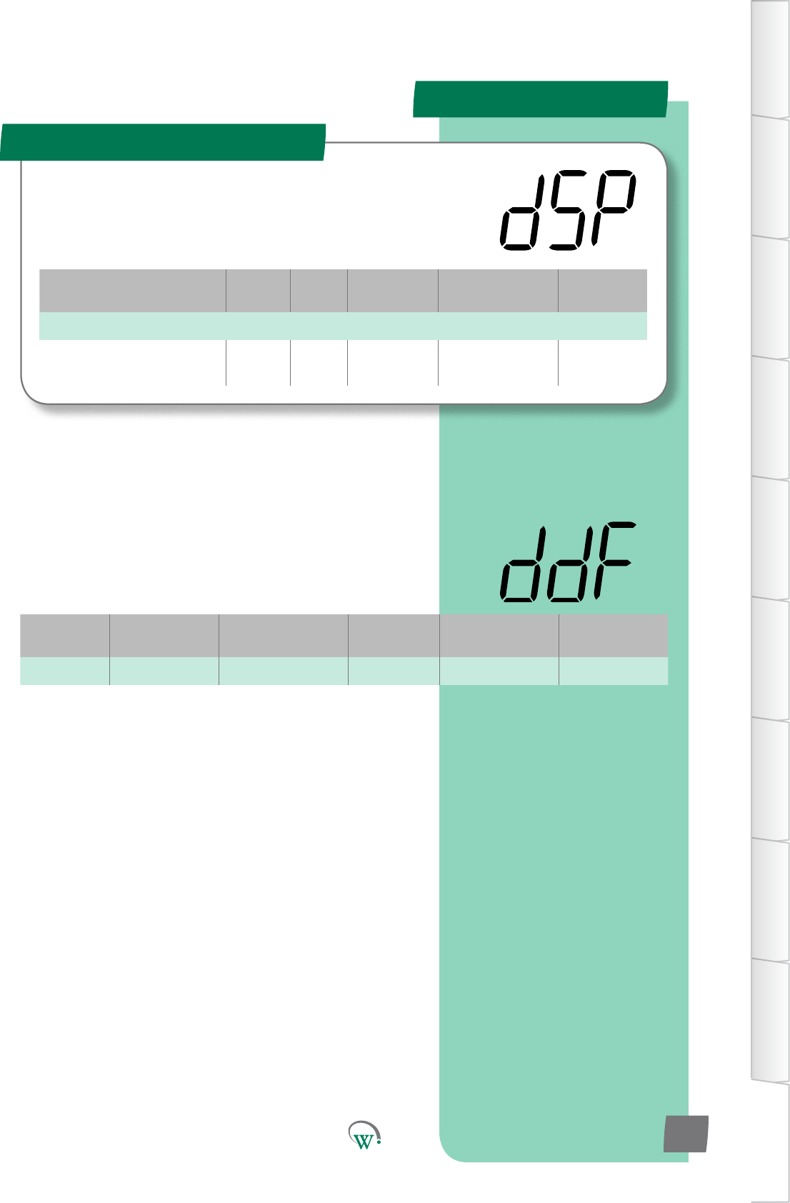
Digital
Display
Funconal
Category ParameterRange Increments
&Units Default Related Menus
ddF Time dISabled 1 secs dISabled udF
Parameter Name Digital
Display Pages Increments
&Units Range Default
TIME
Downwards Temperature
Display Filter ddF 1 secs dISabled dISabled
APPENDIX 2
Display - Adv (dSP)
TABLE OF
CONTENTS
INTRODUCTION
& WARNINGS
DESCRIPTION
& INSTALLATION
FRONT PANEL
USER INTERFACE
GRAPHICAL
USER INTERFACE
PARAMETERS
UPGRADING
FIRMWARE
FAULTS &
ALARMS
TECHNICAL
SPECIFICATION
APPENDICES
PD0006 V2.0 – 08 Jan 2016 123
* DOWNWARDS TEMPERATURE DISPLAY FILTER (ddF)
Themeconstantoftheresponseofthedisplayduringa
downwardstemperaturechangewhenrequiredtobedierent
toanupwardstemperaturechange.Thispreventsmisleading
temperaturespikesbeingshown,whileallowingafast
downwardsresponse.Ifthisisdisabled,thentheltervalue
used will be the same as that chosen for udF.
* Not yet enabled
Theseparameterscongurewhatisshownonthedisplay
duringdierentcontrolmodesandcondions.
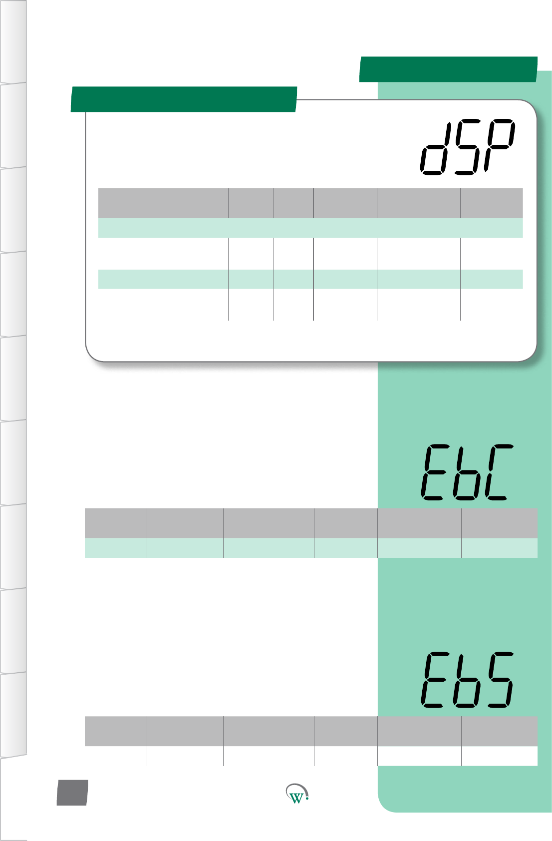
Digital
Display
Funconal
Category ParameterRange Increments
&Units Default Related Menus
EbC Outputs N.C. Port ID N.C.
Digital
Display
Funconal
Category ParameterRange Increments
&Units Default Related Menus
EbS Outputs 0 or 1 integers 0
Parameter Name Digital
Display Pages Increments
&Units Range Default
OUTPUTS
ExternalBuzzerPort
Conguraon EbC Port ID N.C. N.C.
ExternalBuzzerState EbS integers 0 or 1 0
Electronic Expansion Valve
PortConguraon EEC Port ID N.C. N.C.
Hardware - Adv (???)
Theseparameterscongurewhatisshownonthedisplay
duringdierentcontrolmodesandcondions.
APPENDIX 2
TABLE OF
CONTENTS
INTRODUCTION
& WARNINGS
DESCRIPTION
& INSTALLATION
FRONT PANEL
USER INTERFACE
GRAPHICAL
USER INTERFACE PARAMETERS UPGRADING
FIRMWARE
FAULTS &
ALARMS
TECHNICAL
SPECIFICATION APPENDICES
PD0006 V2.0 – 08 Jan 2016
124
EXTERNAL BUZZER PORT CONFIGURATION (EbC)
SelectstheExternalBuzzerPort.PleasealsorefertoExternal
BuzzerState(EBS)
N.C. = Not Connected
AD5* = Switched 24V o/p
*Not yet enabled
EXTERNAL BUZZER STATE (EbS)
SelectsthestatewhentheBuzzeriso.Pleasealsorefertothe
ExternalBuzzerPortConguraon(EBC).
0=Switched24Vopenwhenbuzzero
1=Switched24Vclosedwhenbuzzero
*Funconalitynotyetenabled(SeeEbC)