Welltronic Technology SIGMA-S400 Sigma Industrial remote controller User Manual Sigma handbook EN V120 FCC
Welltronic Technology CO. LTD. Sigma Industrial remote controller Sigma handbook EN V120 FCC
user manual

Sigma
Industrial Remote
Controller
OPRATION GUIDE
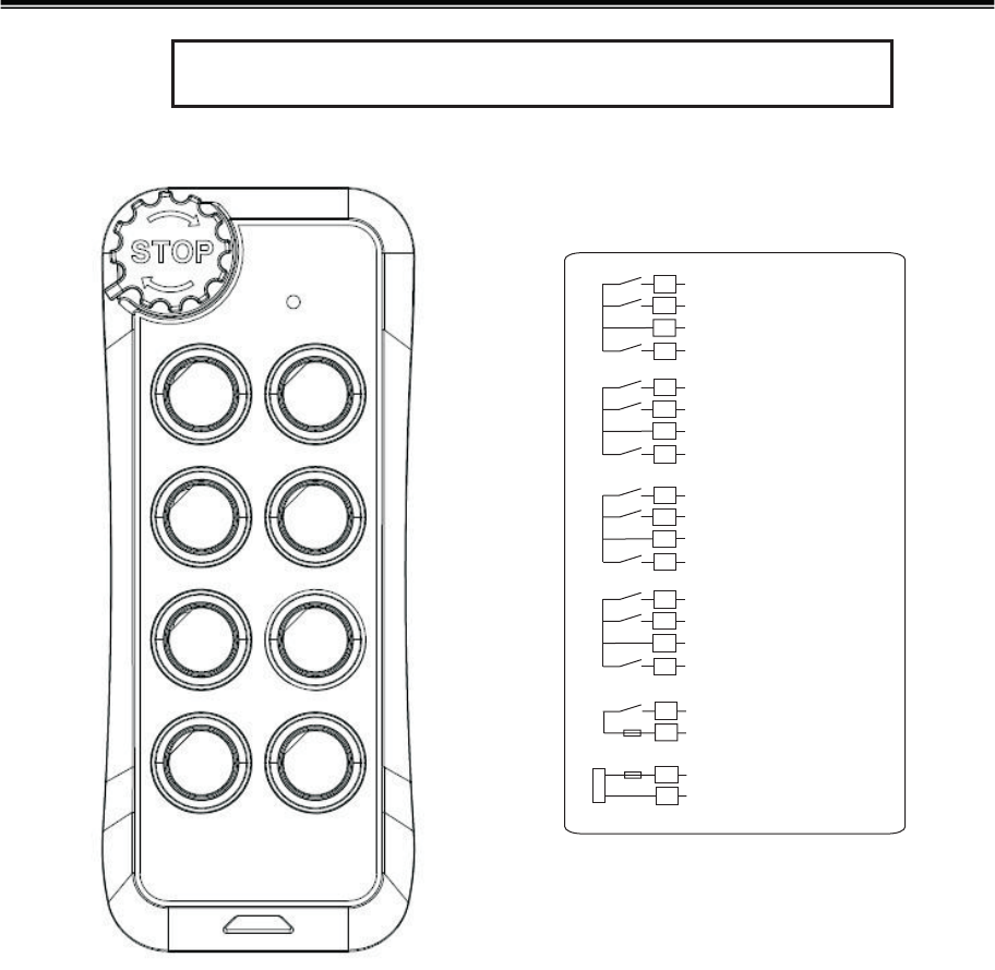
Sigma S300 -6 single step buttons
Sigma S302 -6 Buttons, 2 double step buttons+4single step buttons
Sigma S304 -6 Buttons, 4 double step buttons+2single step buttons
Sigma S306 -6 double step buttons
Sigma S400 -8 single step buttons
Sigma S402 -8 Buttons, 2 double step buttons+6single step buttons
Sigma S404 -8 Buttons, 4 double step buttons+4single step buttons
Sigma S406 -8 Buttons, 6 double step buttons+2single step buttons
Sigma S408 -8 double step buttons
Sigma S40xAB -8 Buttons + A/B select function
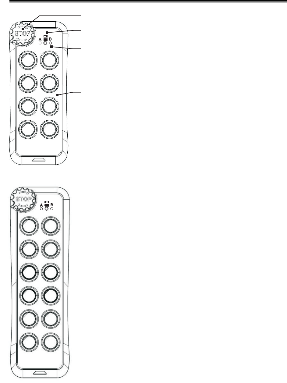
STOP
Button
A/B
indicatior
Status
indicator
Function
buttons
Sigma makes convenience!!
Σ
Σ
Transmitter specification-
Frequence range :
419.2MHz
Transmitting power : 10mW<
Modulation mode :FSK
Transmitting mode :F1D
Security codes : 4.2billion sets
Power source :
2 x AA (LR6) 1.5V alkaline batteries
Power consumption : 8mA<
Opration temperature :
-10°C~+40°C
Size S30x / S40x
S50x / S60x
230mm X 70mm X 43mm
:
175mm X 70mm X 43mm
Weight S30x / S40x 250g
S50x / S60x 310g
(batteries included)
:
Σ
Σ
Indicators of transmittor-
1. Red ON(2sec When STOP Button is pressed down,
the Red LED would light on 2 secs. Now it is in the
STOP Mode.
):
2. reen ON After clockwise turning ON the STOP
button, press any button(or press the Start-up Button,
it depends on the set up) then the Green LED would
light on. It is in the Start-up Procedure.
G:
3. reen flash During operation, the Green LED would
flash every 2 secs.
G:
4. ed flash During operation, if the Red LED flashes
per sec., it is telling you that the battery power is low.
Please renew 2 x AA alkaline batteries.
R:
5. A/B indicator In the type S40xAB,S50xAB and
S60xAB, this indicator can show which hoist (A and/or
B) is controlled.
:
S30x/S40x
Transmitter
S50x/S60x
Transmitter
Σ
Σ
Enclosure rating: IP60
0.03mW
Sigma makes convenience!!
Σ
Σ
Σ
Σ
Receiver specification-
Frequence range : 419.2MHz
Receive Sensitivity : 115dBm<-
Security codes : 4.2billion sets
Power source :AC110V
Power consumption :W<8
Opration temperature :
-10°C~+40°C
Size :
S50x / S60x
240mm X 120mm X90mm
S30x / S40x
220mm X 120mm X75mm
Weight :
S50x / S60x 950g
(Cable excluded)
S30x / S40x 760g
Contacts ability : 5A @ 250VAC
Enclosure rating: IP60
S30x/S40x Receiver
S50x/S60x Receiver
Current rating : 0.5 A

Sigma makes convenience!!
Σ
Σ
Σ
Σ
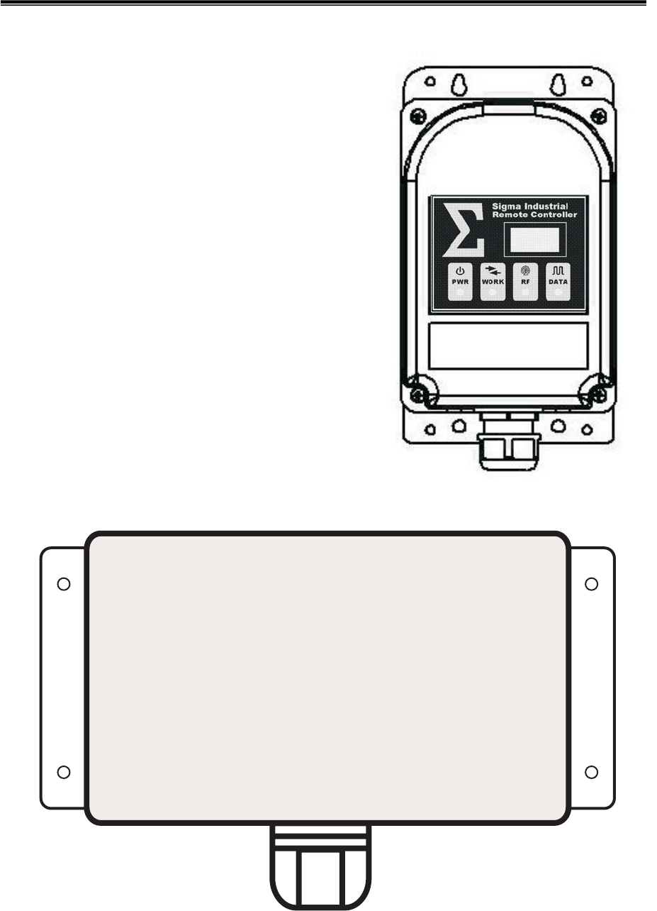
Indicators of receiver -
1. (Green
Power indicator. It lightens on when the power is fed in.
PWR ):
2. :
Green ON - The Receiver got the Start-up command, and is in Working
Mode, ready for the operation anytime.
Green OFF - The Receiver is still in the Stand-by Mode, and it needs to
receive the Start-up command to operate.
Red Flash - The Receiver is in the Security Code Learning Mode.
WORK
3.
Red ON -The RF signal is received.
Red OFF Non RF signal or low signal.
RF :
-
4. :
Red ON - The Receiver is waiting for the RF signal.
Red OFF - The RF signal received and decoded correctly.
Red fast Flash 5 times/sec The RF Signal received, but the Security
Code does not match with each other.
Red slow Flash 1 times/sec The RF signal received, but it is not Sigma's
Code. The receiver is interfered by other RF signals.
DATA
-,
-,
Σ
Σ
Opration of Sigma-
Start up
PWR LED
STOP STOP
Start-up Set-up
program Green LED
Start-up
Start-up WORK LED
Green LED
-
1. Power on the receiver and check the lightening or not.
2. Turn the Button clockwise and release, the will spring up.
(Please placed batteries into the transmitters at first,if have't placed
batteries)
3. Push any button, or the Button (if already set by
). Wait till the Transmitter indicator lightenen,
and the Transmitter will send the command to the Receiver.
Mean time, if the Receiver got the command, its
will lighten. Release the pressed button(s), and the transmitter's
will be off.
4. It is ready, and you can operate now.Sigma
-
1. Push down the Button anytime, the transmitter will send out the
command to the Receiver. The Receiver will cut down any output,
and the should be shut off. The transmitter's will
still lights on and sending command 2 secs.
2. Now, you may power off the Receiver.
Power off
STOP
STOP
WORK LED RED LED
STOP

Sigma makes convenience!!
Σ
Σ
Σ
Σ
Cautions-
①
②
....
If you are not a professional, please do not install or uninstall .
The equipments (or/and ) would be damaged from your errors.
The equipments must have the , ,
, and other safety protecting equipments.
To avoid the influence caused by electromagnetic wave, the location of
receiver should be away from motor/converter/welding machine and so
on which may bring it.
The 's receiver should not be mounted inside of any metal box. It
will weaken the strength of the RF signals, and may cause bad receiving
condition for your operation. The receiver should be mounted outside of
any metal box or other safe places that wouldn't cause bad receiving
condition.
If you will not use for a long time, about a week or more, the
batteries should be taken off to prevent the batteries electrolyte leakage
to etch the .
For PERMANENTLY CONNECTED EQUIPMENT, a readily accessible
disconnect device shall be incorporated external to the equipment
Sigma
Sigma
Sigma
Sigma
.
Main Power N.F.B. Main Power Relay
Limits SW.
PCB
③
④
⑤
⑥
Sigma makes convenience!!
Σ
Σ
Σ
Σ
Sigma Functions-
1. Interlocked -
Left/ right button is interlocked from each other.
3. ON/OFF -
ON/ OFF
FF ON
In this Function, you can set the Left/ Right Button as function.
The Left Button as , and the Right Button as . (This function
could be set by passing EMS.)
O
2. Non_Interlocked -
Left/ right button is not interlocked, and its Two kinds of movements as
below.
①
②
Normal ON OFF
Toggle ON
OFF
- Push down is , and release to be .
- Push down would output . Release and push down again,
output . (This function could be set by passing EMS.)
5. A/B Selector -
Button H
Button L Hoist A Hoist B
OFF A
A+B B OFF
LED A/ B
This Function only supports in S40xAB,
and in S60 x AB, as the A/B Selector to choose , ,
or A + (plus) B to work together. The moves in turns like this, -> ->
-> -> (Repeatedly). At the transmitter, it has the correspond
-ing to indicate which Hoist being controlled.
Button J in S50xAB
Relay 1
Relay 2
Relay 1
Relay 2
Step Step
0012
12
Standard Step Special 2nd Step
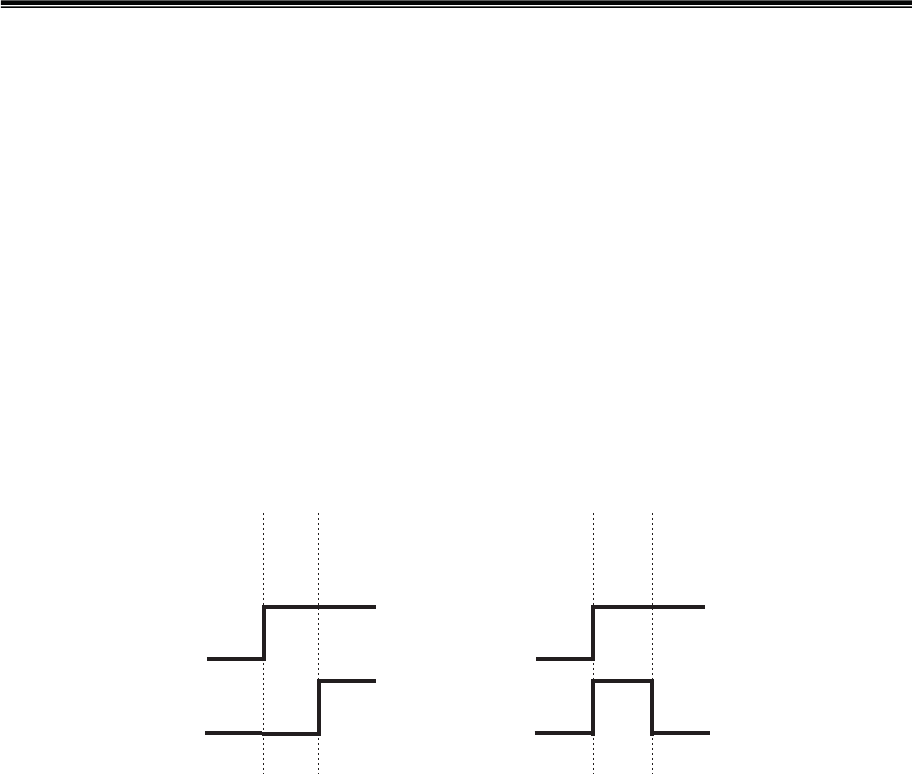
4. Special 2nd Step -
This function only supports the Special Two Step Button, and the
movement is like the below diagram.
6. Start Up mode -
For the safety and convenience, Sigma has 2 kinds of Start-up Mode.
①
②
Any button to start up - More convenience, but less safety.
Specified button to start up - In S4xx, press at the same time, in
S5xx, press , while in S6xx, press to start-up Sigma.
This mode could prevent from starting-up by mistake. It provides you
more safety.
G+H
I+J K+L

Sigma makes convenience!!
Σ
Σ
7. Working Mode -
Sigma has kinds of Working Modes to meet the need of various working
places.
-
①No Auto Stop
STOP
Auto Stop
Continues Link
Auto Stop Continues Link
Auto Stop
STOP
Auto Stop
- During operation, the Transmitter would not be shut
down automatically. You need to press the
Button for shutting down.
After starting up, the Transmitter could be automatic
-ally shut down after the set time-out period.
- After starting up, the Transmitter is set to be continu
-ally sending out the RF signals to the Receiver. This
function is for below purposes.
a. Preventing from any interfering RF signal that may
cut-off the regular signal-sending operation.
b. The equipment will be automatically stopped and
cut-off any Output, if the Receiver moves beyond
the effective remote distance.
Notes -
*1 - In the previous ode and mode:
The Transmitter consistently consumes power all the time. You need
to additionally set up the time. It can be selected among
3, 1, 2, 5, 10 minute(s) for shutting down the Transmitter. To resume
the operation, you can press the Button at first, then release
it to spring-up---- if the occurred.
*2 - Working Modes are for you to choose among Safety, Power Consum
-ption, and Convenience. The below table is for your reference.
Sigma
②
③
②m③
Continues
Link
Auto Stop
No
Auto Stop
Safety
Power
Consumption
Convenience High
Middle
Low
Low
Low
High
High
Low
Middle
Sigma makes convenience!!
Σ
Σ
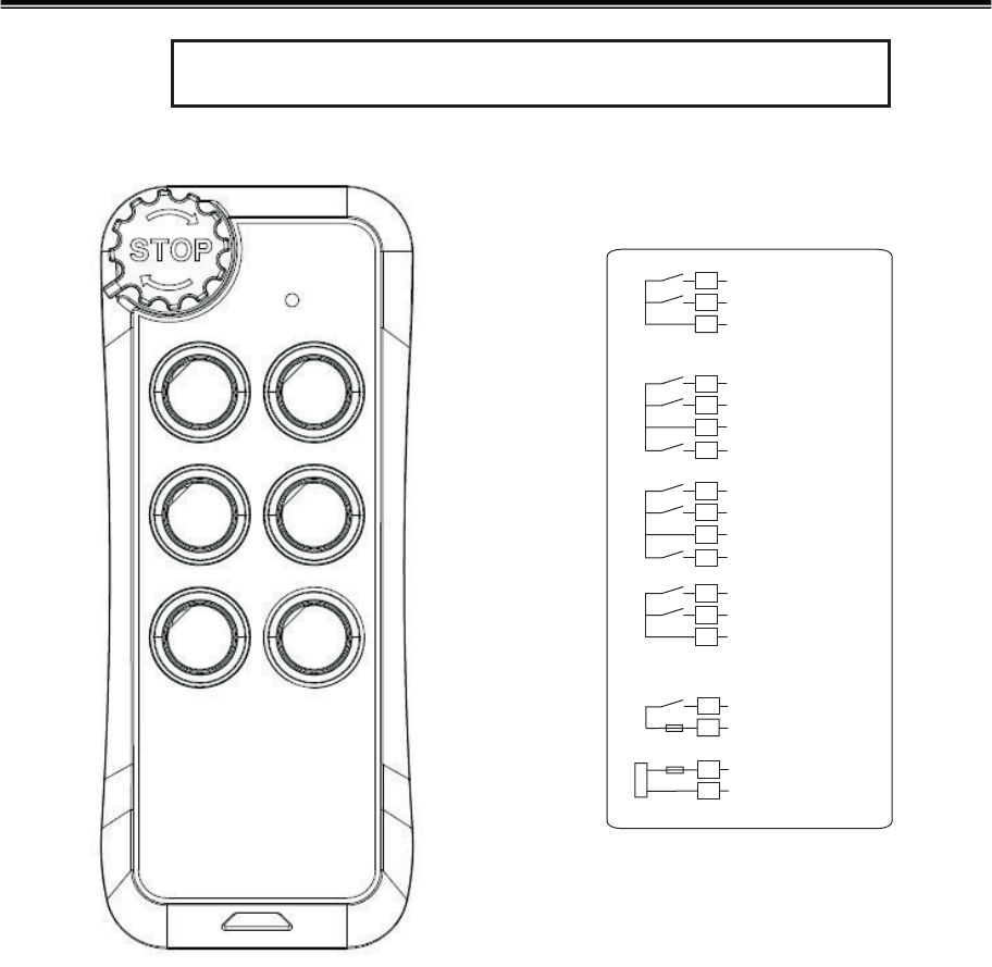
Sigma S300 series installation wiring diagram
Main
Main
1
2
3
13
14
15
16
Power
FUSE 0.5A
A/B Com
AStep 1
BStep 1
4
5
6
C/D Com
CStep 1
DStep 1
18
C/D Step 2
7
8
9
E/F Com
EStep 1
FStep 1
19
E/F Step 2
FUSE 5A
A
B
CD
EF
Sigma S300 series wiring
10
11
12
A/B 2Com
AStep 2
BStep 2
Sigma makes convenience!!
Σ
Σ
Sigma S400 series installation wiring diagram
Main
Main
1
2
3
13
14
15
16
Power
FUSE 0.5A
A/B Com
A Step 1
B Step 1
17
A/B Step 2
4
5
6
C/D Com
C Step 1
D Step 1
18
C/D Step 2
7
8
9
E/F Com
E Step 1
F Step 1
19
E/F Step 2
10
11
12
G/H Com
G Step 1
H Step 1 (Hoist A)
20
G/H Step 2 (Hoist B)
FUSE 5A
A
B
CD
EF
G
H
Sigma S40x series wiring
You are cautioned that changes or modifications not expressly approved by the
party responsible for compliance could void your authority to operate the
equipment.
This device complies with part 15 of the FCC rules. Operation is subject to the
following two conditions
(1) This device may not cause harmful interference and
(2) this device must accept any interference received, including interference
that may cause undesired operation.
-