Westel Wireless Systems CI00063 UHF BASE STATION TRANSCEIVER User Manual 653 003
Westel Wireless Systems Pty Ltd UHF BASE STATION TRANSCEIVER 653 003
Contents
INSTALLATION INSTRUCTIONS

Installation and Operator Handbook Installation Instructions
AMX–MA–00653 Issue 0.03 (USA) 1
TABLE OF CONTENTS
Page
3 Installation Instructions................................................................................................................................ 2
3.1 General .................................................................................................................................................... 2
3.2 Safety Precautions................................................................................................................................... 2
3.3 Site Requirements.................................................................................................................................... 3
3.3.1 Antenna Installation and Safe Operating Distances ................................................................. 3
3.3.2 Desk/Floor Space or Rack Mounting Considerations .............................................................. 3
3.3.3 Lightning Protection................................................................................................................. 4
3.4 Delivery and Unpacking.......................................................................................................................... 4
3.5 Installation............................................................................................................................................... 5
3.5.1 Tools Required......................................................................................................................... 5
3.5.2 Installing the DRB-25 Cabinet................................................................................................. 5
3.5.3 Configuring DRB-25 Identity (Box ID)................................................................................... 6
3.5.4 Installing the Modules.............................................................................................................. 7
3.6 Connections........................................................................................................................................... 11
3.6.1 Grounding Strap ..................................................................................................................... 11
3.6.2 AC Power............................................................................................................................... 11
3.6.3 DC Power............................................................................................................................... 11
3.6.4 Antenna Cabling..................................................................................................................... 11
3.6.5 External Interfaces.................................................................................................................. 11
LIST OF FIGURES
3-1 DRB-25 RACK MOUNTING ARRANGEMENT........................................................................................ 6
3-2 DRB-25 FRONT MODULE POSITIONS..................................................................................................... 7
3-3 DRB-25 WITH LOUDSPEAKER AND MICROPHONE FITTED ............................................................. 8
3-4 DRB-25 REAR MODULE POSITIONS....................................................................................................... 9
Installation and Operator Handbook Installation Instructions
AMX–MA–00653 Issue 0.03 (USA) 2
3 INSTALLATION INSTRUCTIONS
3.1 GENERAL
This chapter provides a detailed description of the installation procedure for the DRB-25 Dual Channel Radio
System and should be read before starting the installation. Use the Installation Instructions in conjunction
with the configuration checklist for the specific system being installed.
3.2 SAFETY PRECAUTIONS
Observe standard safety procedures for the handling of electronic equipment:
WARNING
FOLLOW CORRECT LIFTING PROCEDURES FOR HEAVY
ELECTRONIC EQUIPMENT.
ATTENTION
OBSERVE
PRECAUTIONS
FOR HANDLING
ELECTROSTATIC
SENSITIVE
DEVICES
When removing or handling cards, use an anti-static wrist strap
connected to ground and always place the card on an anti-static mat
Handle modules by their edges and do not touch components or
connectors.
Avoid placing the DRB-25 near any source of excessive heat
Avoid placing the DRB-25 near a naked flame
Avoid placing the DRB-25 in a wet or damp location
Do not subject the DRB-25 to severe mechanical shock

Installation and Operator Handbook Installation Instructions
AMX–MA–00653 Issue 0.03 (USA) 3
3.3 SITE REQUIREMENTS
Before installing the DRB-25 at the operating site, the following details regarding antenna installation and
safe operating distances, desk or floor space, rack clearance and lightning protection should be considered.
3.3.1 Antenna Installation and Safe Operating Distances
Use only manufacturer or dealer supplied antenna.
Antenna Minimum Safe Distance: 70 cm, 50% Duty Cycle.
Antenna Gain: zero dBd referenced to a dipole.
The Federal Communications Commission has adopted a safety standard for human exposure to RF (Radio
Frequency) energy which is below the OSHA Occupational Safety and Health Act) limits.
Antenna Mounting: The antenna supplied by the manufacturer or radio dealer must not be mounted at a
location such that during radio transmission, any person or persons can come closer than the above indicated
minimum safe distance to the antenna i.e. 70 cm.
To comply with current FCC RF Exposure limits, the antenna must be installed at or exceeding the minimum
safe distance shown above, and in accordance with the requirements of the antenna manufacturer or supplier.
Base Station Installation: The antenna should be fixed-mounted on an outdoor permanent structure. RF
Exposure compliance must be addressed at the time of installation.
Antenna Substitution: Do not substitute any antenna for the one supplied or recommended by the
manufacturer or radio dealer. You may be exposing person or persons to excess radio frequency radiation.
You may contact your radio dealer or the manufacturer for further instructions.
Warning: Maintain a separation distance from the antenna to a person(s) of at least 70 cm. You, as the
qualified end-user of this radio device must control the exposure conditions of bystanders to ensure the
minimum separation distance (above) is maintained between the antenna and nearby persons for satisfying RF
Exposure compliance. The operation of this transmitter must satisfy the requirements of 0ccupational
/Controlled Exposure Environment, for work-related use. Transmit only when person(s) are at least the
minimum distance from the properly installed, externally mounted antenna.
3.3.2 Desk/Floor Space or Rack Mounting Considerations
The DRB-25 is 19 inches (483 mm) wide (standard 19 inch rack mountable), 14 inches (355 mm) high, 17.4
inches (440 mm) deep, and weighs 58 lb (26 kg) for a single radio configuration, or 81 lb (37 kg) for a dual
radio configuration. When mounting the DRB-25 Cabinet:
• Ensure that the DRB-25 is securely mounted.
• Ensure that the DRB-25 air vents are clear of obstructions.
• Provide sufficient space on all sides to of the DRB-25 to allow adequate access to the equipment and
cables.
• Ensure that there is adequate space for entry of external cables (antenna and AC power cables) at the
rear of the unit without the need for small radius bends.

Installation and Operator Handbook Installation Instructions
AMX–MA–00653 Issue 0.03 (USA) 4
3.3.3 Lightning Protection
To minimize damage to equipment, or injury to maintainers, a complete system of lightning protection and
grounding connections should be installed. The following points should be considered:
• All down conductors, bonding interconnections, ground rings and radial tapes should be un-insulated
solid copper tape at least 25 x 3 mm in cross section. All connection clamps and supports should be
protected by non-reactive paste or tape.
• The use of gas lightning arresters or metal oxide varistors is recommended on line interfaces, including
antenna cables.
• Protected test points should be included where appropriate and sacrificial grounding lugs should be
clearly marked and accessible for periodic inspection and replacement if necessary.
• Use a large copper strap to take outer cable casings to a central ground bonding point.
• Antenna support structures, whether on the ground or on a building, should be connected to an o ring
arrangement (or equivalent) via sacrificial ground lugs.
• A ground ring consists of copper tape with driver ground electrodes or radial tapes around the base of
the structure (as close to it as possible), buried approximately 24 inches (0.6 m), where soil conditions
allow.
• The main building and any other metalwork structures within 3m should be connected to a ground
ring.
3.4 DELIVERY AND UNPACKING
The DRB-25 cabinet and supporting modules are packed and transported in customized packages which
conform to best commercial practices for transportation and protection of electronic assemblies.
The DRB-25 cabinet is delivered complete, requiring only the fitting of the plug in modules.
In addition to the DRB-25 cabinet, the Modules which may be supplied in separate packages are:
• One or two Power Supply Modules.
• One or two Power Amplifier Modules.
• One or two Transceiver Modules.
• Controller Module.
• Interface Module.
In addition a programming kit may be provided, including a programming disk and interface cable.
Before unpacking, examine the packages for evidence of external damage, water ingress or vermin activity
which may have occurred during transportation.
Examine the delivery docket or installation check list to confirm that the correct items for the intended DRB-
25 configuration has been delivered.
Notify the supplier or its agent immediately if any discrepancy is noted.

Installation and Operator Handbook Installation Instructions
AMX–MA–00653 Issue 0.03 (USA) 5
Unpack the DRB-25 as follows:
• Carefully remove the DRB-25 cabinet from its packaging and relocate to a convenient level work
surface.
• Remove all protective wrapping and inspect the cabinet for signs of damage or loose parts. Notify the
supplier or its agent immediately if any is noted.
• Remove each of the modules in turn from their packages, unwrap and inspect as for the cabinet.
Notify the supplier or its agent immediately if any damage or loose parts are noted.
3.5 INSTALLATION
Take care to align each module correctly into its guide rails. Ensure
that the module is correctly mated into the backplane of the DRB-25
and the connectors are firmly seated. Failure to do so may result in
damage to the module or DRB-25 system.
3.5.1 Tools Required
The following tools should be on hand during installation:
• Flat-bladed screwdrivers (small, medium and large).
• Cross-recessed (Phillips) screwdriver (large and medium).
• Cable ties and cutters.
• 9/32 inch (7 mm) hexagonal nut driver.
• Multimeter with pointed probes for continuity and DC voltage measurements.
3.5.2 Installing the DRB-25 Cabinet
If the DRB-25 is to be desk mounted then screw the supplied feet to the four threaded inserts on the underside
of the case and position the case as required.
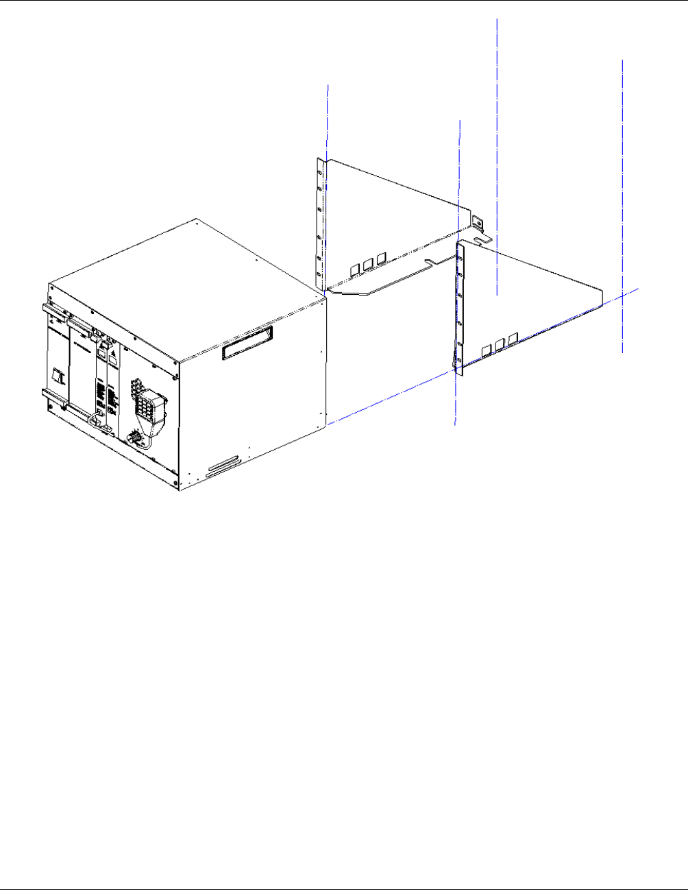
If the cabinet is to be rack-mounted then assemble the rack mounting brackets and case as shown in Figure 3-
1: DRB-25 Rack Mounting Arrangement :
1. Fit the brackets to the rack using the caged nuts and bolt supplied.
2. Slide the DRB-25 case into the brackets.
3. Fix the DRB-25 in place by locating the two studs at the rear of the case through the hole in each
bracket, and secure using the nuts supplied.
4. Set the DRB-25’s Identity (Box ID) and fit the modules as described in the following sections.
Installation and Operator Handbook Installation Instructions
AMX–MA–00653 Issue 0.03 (USA) 6
Figure 3-1 DRB-25 Rack Mounting Arrangement
3.5.3 Configuring DRB-25 Identity (Box ID)
An 8-way DIP switch on the backplane adjacent to Transceiver 2 enables a Box ID to be set for each DRB-25.
The switch is accessed from the front of the unit with the modules removed. A total of 256 identities are
available.
The Box ID is used by each Transceiver to determine its default settings on power-up. Transceiver modules
can be programmed with up to 512 operating channels, and the default operating channel for each Transceiver
is determined by the DRB-25 Box ID as detailed in Appendix A Table A-1.
DRB-25 Box ID settings may be defined in a plan that covers all DRB-25 units in the network. The Box ID is
also used by the Controller Module for network management purposes to enable it to identify itself within a
network.
The default factory setting is a box identity of zero.
To set the DIP switches:
1. LOCATE the DIP switch on the upper right of the backplane, through the front of the DRB-25 case
without the plug in modules fitted.
Installation and Operator Handbook Installation Instructions
AMX–MA–00653 Issue 0.03 (USA) 7
2. Using a screwdriver or pen, set the eight sections of the DIP switch to the desired Box ID, according
to and the intended DRB-25 Box numbering plan.
3. The Switch 1 (LSB) is the top switch; Switch 8 (MSB) is the lower switch. OFF is to the left, ON is to
the right.
3.5.4 Installing the Modules
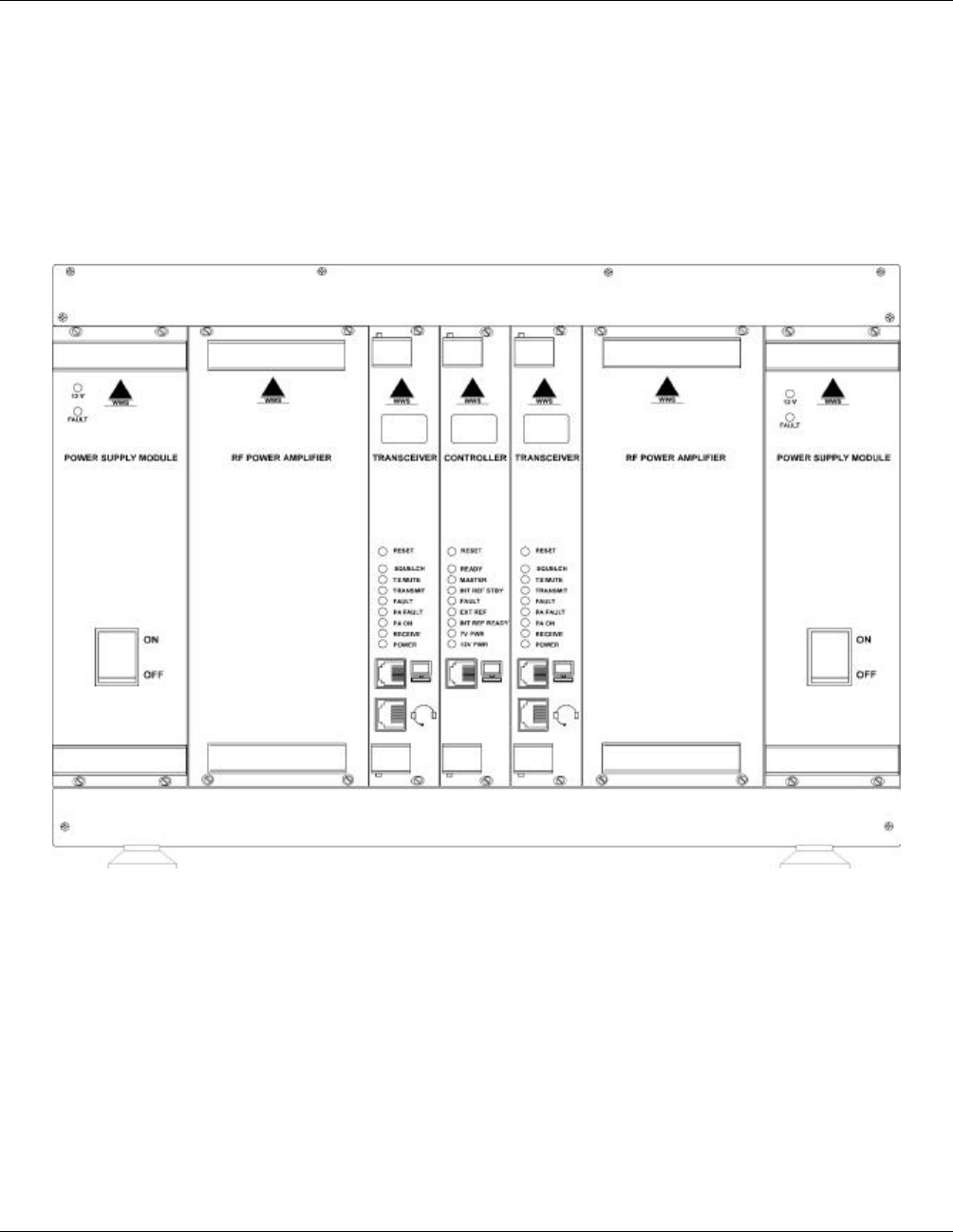
Refer to the following figures (Figure 3-2, Figure 3-3 and Figure 3-4) to identify the correct position for each
module within the DRB-25 cabinet. Install the supplied modules as detailed in the following paragraphs.
Figure 3-2 DRB-25 Front Module Positions
Installation and Operator Handbook Installation Instructions
AMX–MA–00653 Issue 0.03 (USA) 8
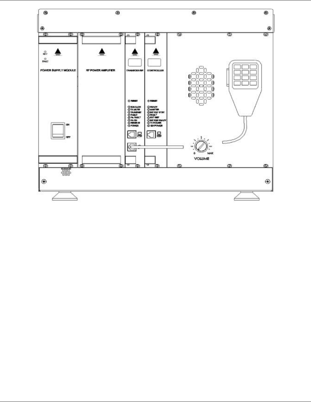
Figure 3-3 DRB-25 with Loudspeaker and Microphone fitted
Installation and Operator Handbook Installation Instructions
AMX–MA–00653 Issue 0.03 (USA) 9
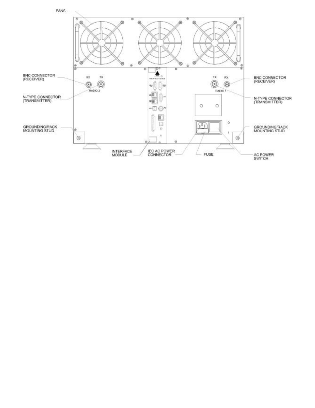
Figure 3-4 DRB-25 Rear Module Positions
3.5.4.1 Power Supply Module
To install the Power Supply Module:
1. Carefully insert the Power Supply Module into its position from the front of the cabinet by aligning the
guide rails and pushing home until the backplane connector is correctly mated and the panel is flush
with the adjacent panels.
2. Using a medium sized flat-bladed screwdriver, secure the Module with the four captive collar screws.
Do not over-tighten.
3. If two Power Supply Modules are supplied, repeat for the other module.
3.4.4.2 Power Amplifier Module
To install the Power Amplifier Module:
1. Locate the coax lead with a right-angled N-type connector. Stretch the lead out of the box and partially
insert the Power Amplifier into its card slot. Attach the N-type connector to the mating connector on
the Power Amplifier, then carefully insert the Power Amplifier Module fully into position from the
front of the cabinet. Push the module home so that the backplane connector is correctly mated and the
panel is flush with the adjacent panels.
2. Using a medium sized flat-bladed screwdriver, secure the Module using the four captive collar screws.
Do not over-tighten.
3. If two Power Amplifier Modules are supplied, repeat for the other module.

Installation and Operator Handbook Installation Instructions
AMX–MA–00653 Issue 0.03 (USA) 10
3.5.4.3 Transceiver Module
To install the Transceiver Module:
1. Carefully insert the Transceiver Module into its position from the front of the cabinet by aligning the
guide rails and pushing home until the backplane connector is correctly mated and the panel is flush
with the adjacent panels.
2. Using a medium sized flat-bladed screwdriver, secure the Module using the two captive collar screws.
Do not over-tighten.
3. If two Transceiver Modules are supplied repeat for the other module.
3.5.4.4 Controller Module
To install the Controller Module:
1. Carefully insert the Controller Module into its position from the front of the cabinet by aligning the
guide rails and pushing home until the backplane connector is correctly mated and the panel is flush
with the adjacent panels.
2. Using a medium sized flat-bladed screwdriver, secure the Module using the two captive collar screws.
Do not over-tighten.
3.5.4.5 Interface Module
To install the Interface Module:
1. Carefully insert the Interface Module into its position from the rear of the cabinet by aligning the guide
rails and pushing home until the backplane connector is correctly mated and the panel is flush with the
adjacent panels.
2. Using a medium sized Phillips screwdriver, secure the Module using the two captive screws. Do not
over-tighten.
3.5.4.6 Loudspeaker Panel and Microphone
A DRB-25 configured with only one transceiver may have a Loudspeaker Panel, (or a Loudspeaker Panel and
microphone) installed in place of Transceiver 2 and its associated PA and power supply.
To install the Loudspeaker Panel and microphone:
1. The panel is installed on the right hand side of a single channel DRB-25 in place of Transceiver 2. An
internal cable is connected from the rear of the loudspeaker panel to the connector marked “TR1
Audio” on the DRB-25 backplane adjacent to Transceiver 2.
2. Carefully align the panel and using a medium sized flat-bladed screwdriver secure the panel using the
six captive collar screws.
3. If the panel is supplied with a microphone, the cable is connected to the Transceiver 1 front panel
audio connector (RJ45).

Installation and Operator Handbook Installation Instructions
AMX–MA–00653 Issue 0.03 (USA) 11
3.6 CONNECTIONS
3.6.1 Grounding Strap
Before connecting the DRB-25, it is recommended that a secure ground strap be connected from the
grounding stud at the rear left hand side of the DRB-25 case to a substantial ground system:
1. Locate the primary grounding stud at the rear of the chassis on the lower left hand side.
2. Connect a grounding strap from an external grounding point or ground ring to the chassis primary
grounding stud.
3. Ensure good electrical contact and security of all connections.
3.6.2 AC Power
An IEC standard AC power cable is provided with the AC and DC revert configurations. Connect the AC
power cable as follows:
1. Set the power switch on the rear of the DRB-25 to OFF.
2. Plug-in the IEC connector of the cable to the recessed IEC plug on the rear of the DRB-25.
3. Connect the other end of the AC power cable to a properly protected and grounded AC power outlet.
3.6.3 DC Power
External DC power connection for DC and DC revert configurations is via a 2-way terminal block mounted
on the rear of the DRB-25 above the mains input receptacle. Connect DC power cable as follows:
1. Ensure that DC power is not applied to the cables being connected to the DRB-25.
2. Strip back 3/8” of cable insulation on both positive and negative cables.
3. Insert positive supply into the topmost terminal (Red)and negative supply into the lower terminal
(Black).
4. Secure both terminal screws and apply DC power to cable.
DC configurations include an internal fuse within the DRB-25, however to allow isolation of the unit it is
recommended that a circuit breaker or DC switch is placed in the DC circuit to the DRB-25.
3.6.4 Antenna Cabling
The length and type of antenna cabling required depends on the system configuration and will be supplied
separately. Connect the Transmit (N-type) and Receive (BNC type) cables to the Transmit and Receive
connectors on the rear of the cabinet to the Antenna system.
3.6.5 External Interfaces
The DRB-25 supports the following external interfaces:
• Transceiver Module audio connector

Installation and Operator Handbook Installation Instructions
AMX–MA–00653 Issue 0.03 (USA) 12
• Transceiver Module programming connector.
• Radio serial data.
• Analog line connections for PSTN, PBX, Microwave or tone remote control unit.
• RS-485 serial data (for future use as APCO Project 25 Fixed Station Interface (Ef) and digital console
interface.
• Ethernet connection for future use as a network management interface.
• General purpose input/output lines.
• External 10 MHz reference source input.
• Standby power to maintain temperature of reference oscillator oven during power outages.
• -48 V DC input for operation of E & M signalling interface.
3.6.5.1 Transceiver Module Audio Connector
Function: Connects external microphone or speaker or both to Transceiver Module
Located: Transceiver Module front panel (lower connector)
Connector: RJ45
Pin allocation: (Pin 1 is the top pin looking from the front of the module)
Pin Function
1 Microphone audio
2 Ground
3 Line/speaker output (link selectable on the Tx module)
4 Microphone supply (+12 V)
5 PTT (Active Low)
6 Monitor (Active Low)
7 SW1 (Active Low)
8 SW2 (Active Low)

Installation and Operator Handbook Installation Instructions
AMX–MA–00653 Issue 0.03 (USA) 13
3.6.5.2 Transceiver Module Programming Connector
Function: Connects programming PC to Transceiver Module
Located: Transceiver Module front panel (upper connector)
Electrical: RS-232
Connector: RJ11
Pin allocation: (Pin 1 is the top pin looking from the front of the module)
Pin Function
1 N/C
2 Reserved
3 Transmit data (output)
4 Receive data (input)
5 Ground
6 N/C
3.6.5.3 Controller Module Serial Data Connector
Function: Connects Diagnostic PC to DRB-25
Located: Controller Module front panel
Electrical: RS-232
Connector: RJ11
Pin allocation: (Pin 1 is the top pin looking from the front of the module)
Pin Function
1 RTS (outpuyt)
2 CD (input)
3 Transmit data (output)
4 Receive data (input)
5 Ground
6 CTS (input)
3.6.5.4 Radio Serial Data
Function: APCO Project 25 Data Host Interface (Ed) for circuit switched data
Status: Future enhancement, software upgrade
Located: Interface Module
Label: Serial One, Serial Two (one per transceiver module)
Electrical: RS-232
Connector: DB9 (female)

Installation and Operator Handbook Installation Instructions
AMX–MA–00653 Issue 0.03 (USA) 14
Pin allocation:
Pin Function
1 Reserved
2 Receive data (input)
3 Transmit data (output)
4 Reserved
5 Ground
6 Reserved
7 Reserved
8 Reserved
9 Reserved
3.6.5.5 Analog Line Connection
Function: Provides line connections for PSTN, PBX, Microwave or tone remote control unit. (4 wire
functional, 2 wire future enhancement).
Located: Interface Module
Label: Line One and Line Two (one per transceiver module)
Electrical: See table below
Connector: RJ45
Pin allocation: (Pin 1 is the lower pin on the connector)
Pin Function (2 wire) Function (4 wire)
1 Reserved SB
2 Reserved M lead
3 Reserved DRB-25 Receive Audio (+) - balanced signal, 600R,
0 dBm (nominal)
4 Ring DRB-25 Transmit Audio (+) - balanced signal, 600R,
0 dBm (nominal)
5 Tip DRB-25 Transmit Audio (-) - balanced signal, 600R,
0 dBm (nominal)
6 Reserved DRB-25 Receive Audio (-) - balanced signal, 600R,
0 dBm (nominal)
7 Reserved SG
8 Reserved E
4 Wire Console/Exchange Pin Allocation: The default configuration of the 4 wire interface is as a console
interface with pin allocation as shown above, suitable for connection to a tone remote console.
The interface may be reconfigured by jumper placement to an exchange interface suitable for connection to a
PSTN or PABX network. The exchange configuration has pin 3 connected to DRB-25 Transmit Audio (-), pin
4 connected to DRB-25 Receive Audio (+), and is otherwise the same as the console configuration pin
allocation.

Installation and Operator Handbook Installation Instructions
AMX–MA–00653 Issue 0.03 (USA) 15
To configure the pin allocation as either a console or exchange interface place the jumpers on connectors
XL5, XL6 (line 1) and XL3, XL4 (line 2) as follows:
Line 1 Line 2
Connectors XL5 & XL6 XL3 & XL4
Console configuration jumper position (default) pin 1- pin 2 pin 1- pin 2
Exchange configuration jumper position pin 2- pin 3 pin 2- pin 3
3.6.5.6 RS-485 serial data
Function: Provides vocoded voice for APCO Project 25 Fixed Station Interface (Ef) or for a digital
console interface. Future enhancement, software upgrade.
Located: Interface Module front panel
Label: LINK
Electrical: RS-485
Connector: DB9 (male)
Pin allocation:
Pin Function
1 Reserved
2 Transmit data + (out of IAC)
3 Transmit data - (out of IAC)
4 Reserved
5 Ground
6 Reserved
7 Receive data + (into IAC)
8 Receive data - (into IAC)
9 Reserved
3.6.5.7 Ethernet
Function: Network management interface and APCO Project 25 Data Host Interface (Ed) for packet
data.
Status: Future enhancement, software upgrade.
Located: Interface Module
Label: NET
Electrical: 10Base-T
Connector: RJ45

Installation and Operator Handbook Installation Instructions
AMX–MA–00653 Issue 0.03 (USA) 16
Pin allocation: (Pin 1 is the lower pin of the connector)
Pin Function
1 Transmit data + (out of IDC)
2 Transmit data - (out of IDC)
3 Receive data + (into IAC)
4 Reserved
5 Reserved
6 Receive data - (into IAC)
7 Reserved
8 Reserved
3.6.5.8 General Purpose Input/Output Lines
Function: Provides 6 general purpose inputs and outputs for control of transmit/receive antenna
change-over relays, external site alarms and functions.
Located: Interface Module
Label: I/O
Connector: DB25 (female)
Pin allocation:
Pin Function
1 Antenna relay output radio 1: +
14 Antenna relay output radio 1: -
2 Antenna relay output radio 2: +
15 Antenna relay output radio 2: -
3 General purpose output 3: +
16 General purpose output 3: -
4 General purpose output 4: +
17 General purpose output 4: -
5 General purpose output 5: +
18 General purpose output 5: -
6 General purpose output 6: +
19 General purpose output 6: -
7 Transmit disable input radio 1: +
20 Transmit disable input radio 1: -
8 Transmit disable input radio 2: +
21 Transmit disable input radio 2: -
9 General purpose input 3: +
22 General purpose input 3: -
10 General purpose input 4: +
23 General purpose input 4: -
11 General purpose input 5: +
24 General purpose input 5: -

Installation and Operator Handbook Installation Instructions
AMX–MA–00653 Issue 0.03 (USA) 17
Pin Function
12 General purpose input 6: +
25 General purpose input 6: -
13 Ground
Transmit disable inputs: When the + input is connected to +12 V and the - input to ground the relevant
transmitter is disabled.
Antenna relay outputs: Ensure that 4 links are present on Interface Module XM3. When the radio PTT is
active, the + output is connected to +12V, the - output is connected to ground
3.6.5.9 External 10 MHz reference source
Function: Provides 10 MHz input. When present automatically used in preference to internal 10
MHz reference
Located: Interface Module
Label: REF IN
Electrical: Level between 450 mV peak-peak and 4v peak-peak, impedance 50 Ohm
Connector: BNC
Pin allocation:
Pin Function
Inner External reference input
Outer Ground
3.6.5.10 Standby power
Function: Maintain internal reference oscillator during power outages.
Located: Interface Module
Label: STDBY IN
Electrical: 12 V DC (+/- 5%) input, max. current 1A
Connector: 2 pin (male). Mating plug: Phoenix Contact MSTB 2.5/2-ST-5.08
Pin allocation:
Pin Function
Upper +12 V DC ground (0 V)
Lower +12 V DC input
3.6.5.11 -48 V DC input
Function: Provides –48 V DC input for E/M signaling
Located: Interface Module
Label: -48 V DC
Connector: 2 pin (male) Mating plug: Phoenix Contact MSTB 2.5/2-ST-5.08
Pin allocation:
Pin Function
Upper -48 V DC ground (0 V)

Installation and Operator Handbook Installation Instructions
AMX–MA–00653 Issue 0.03 (USA) 18
Pin Function
Lower -48 V DC input