Westell 7500XX-07 Versalink Wifi Device User Manual

Westell Inc Versalink Wifi Device

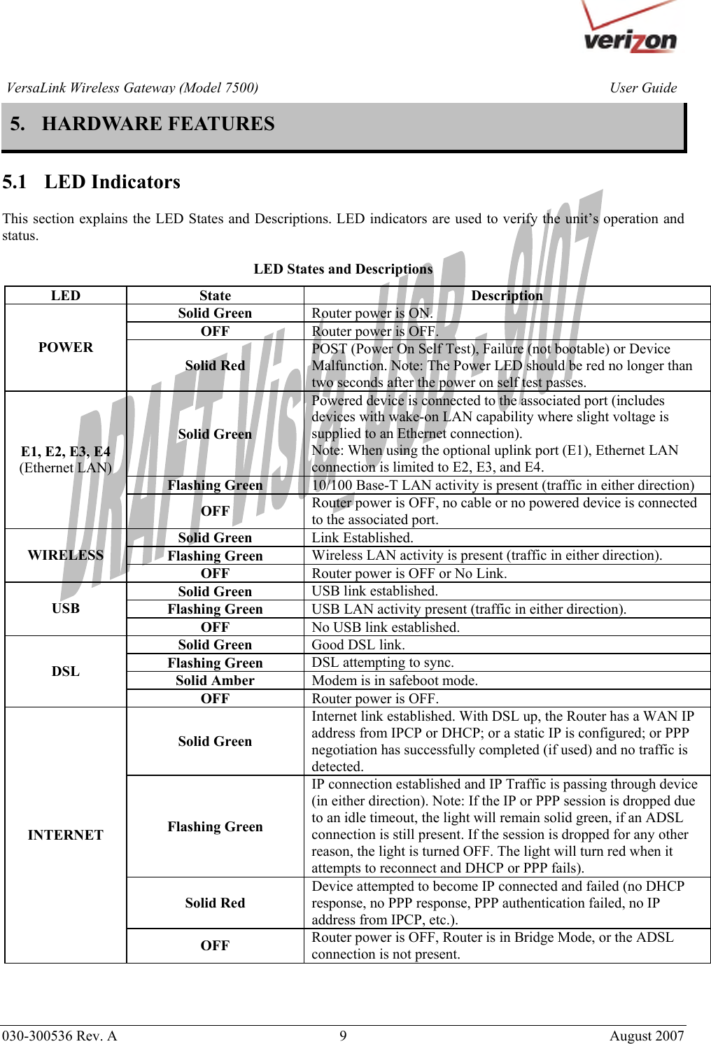
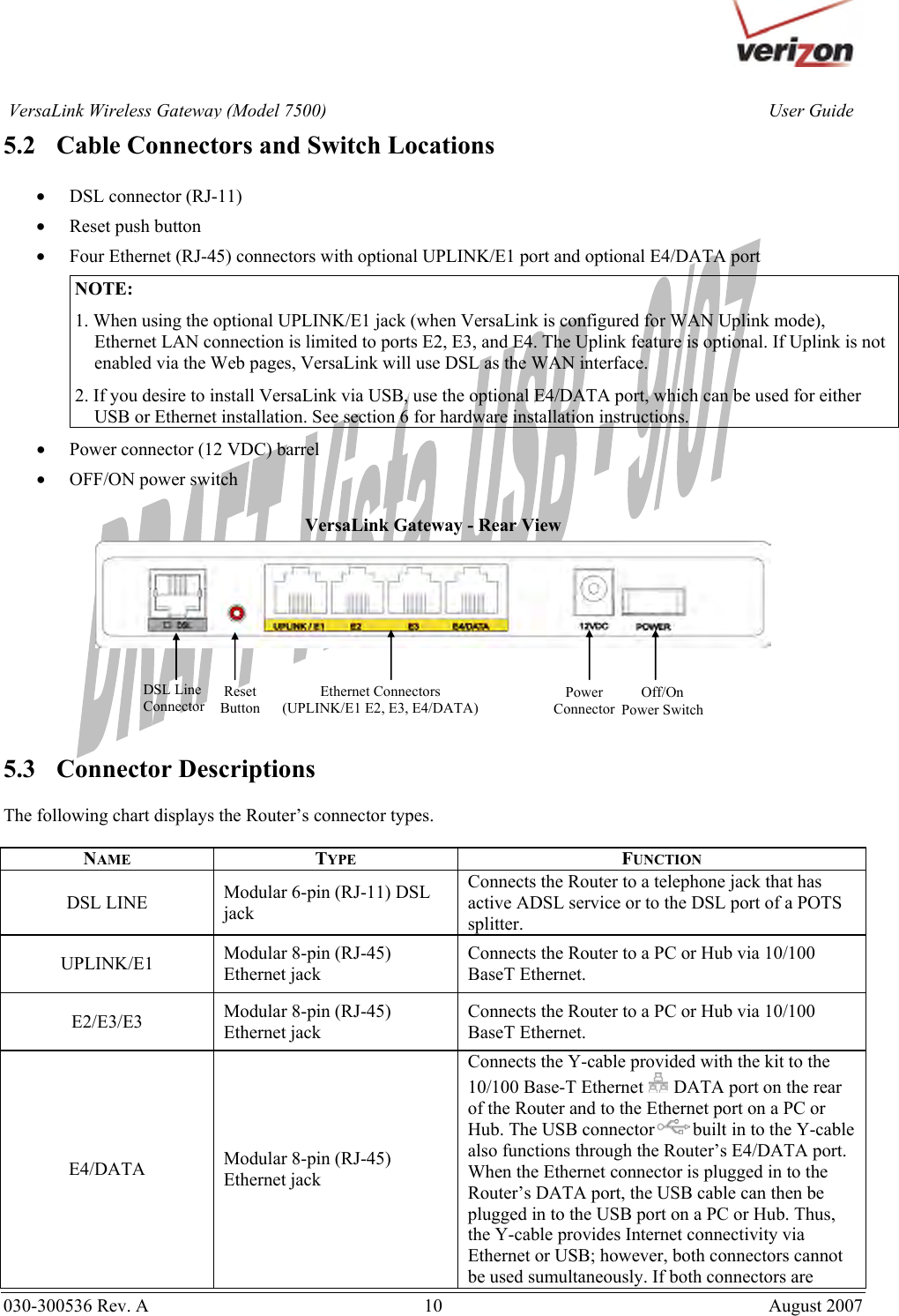
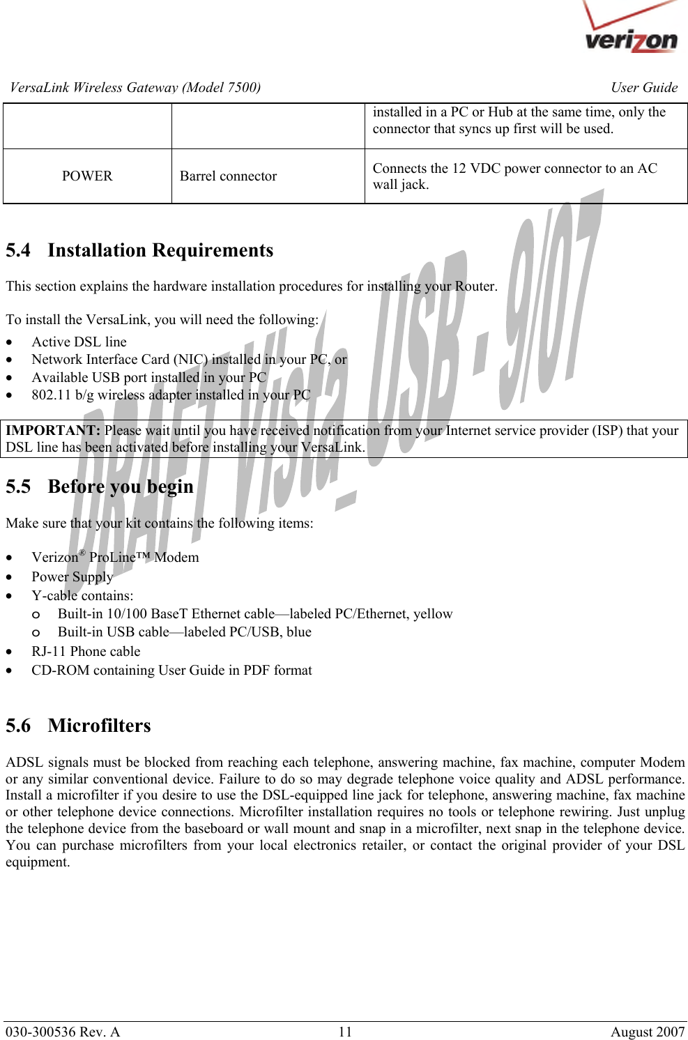
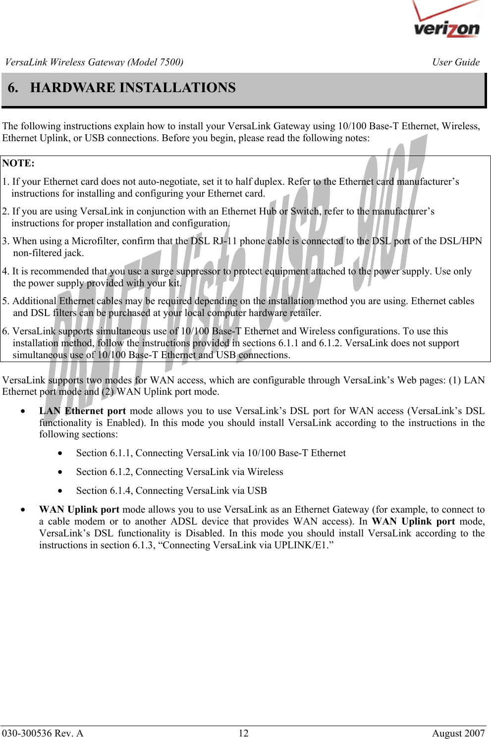
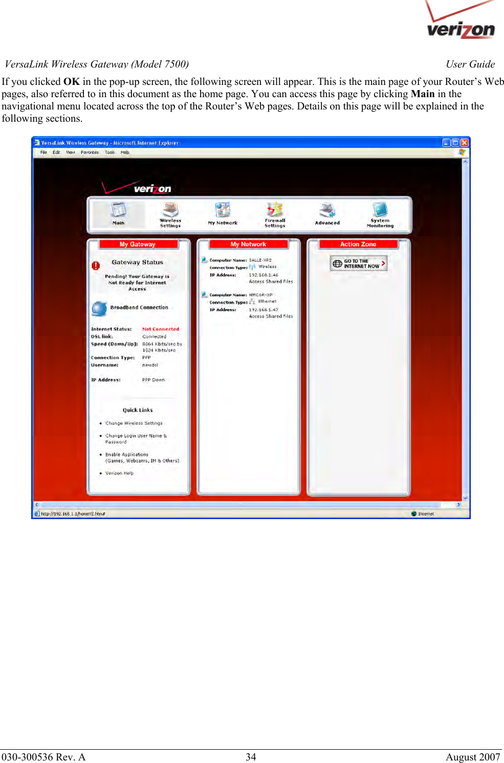
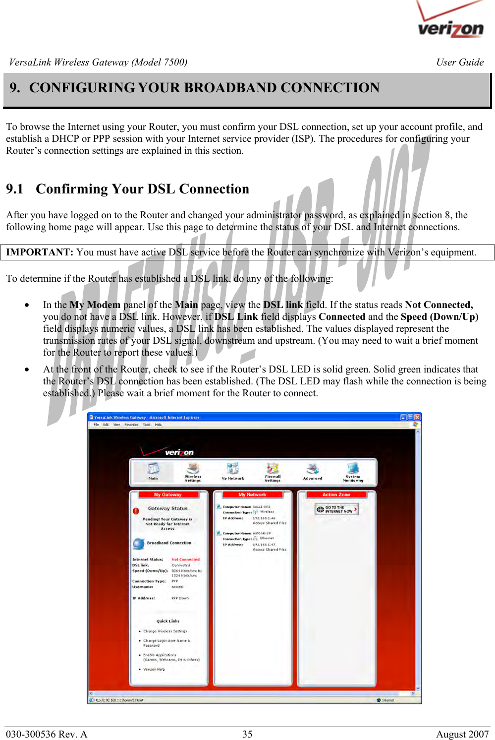
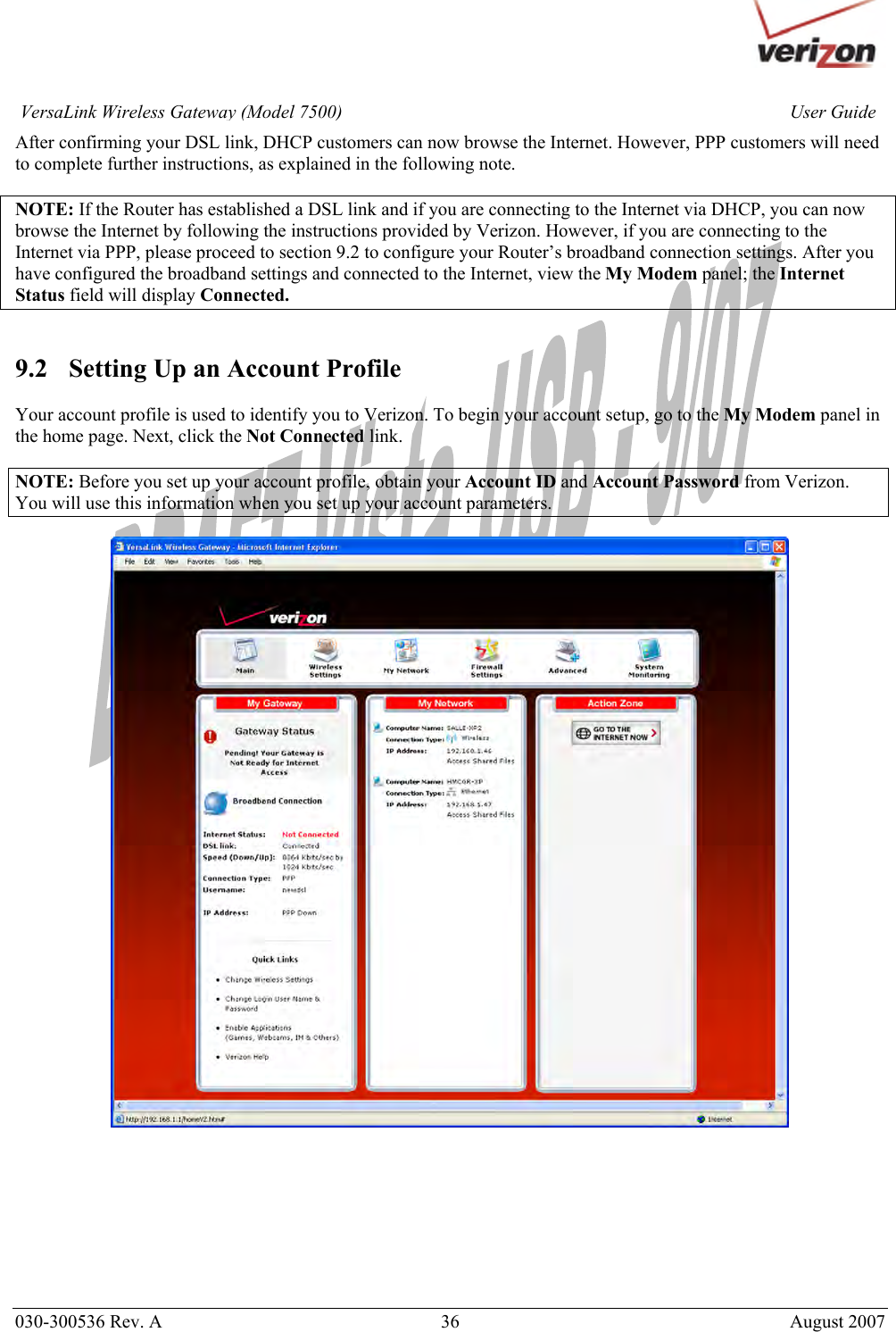
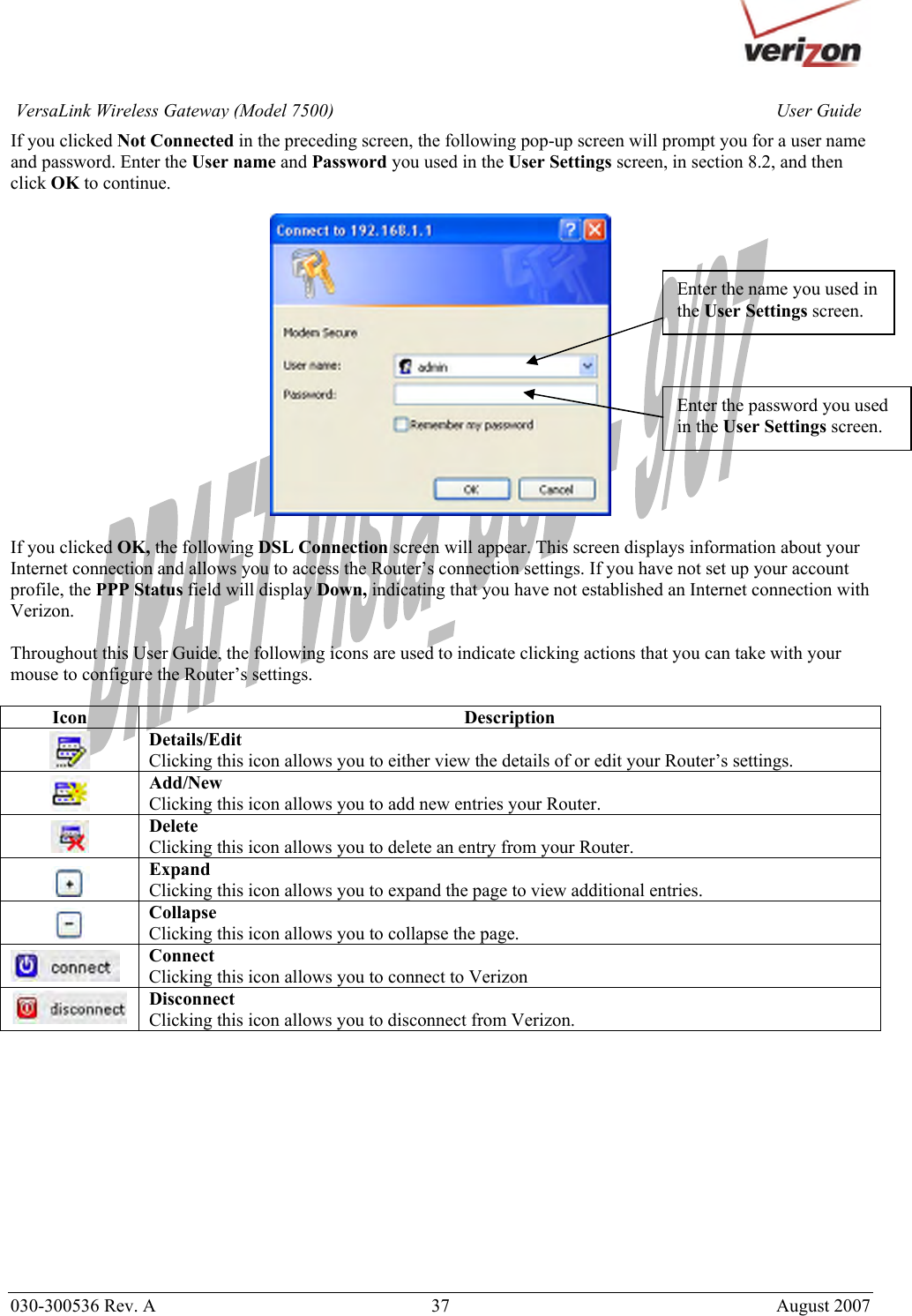
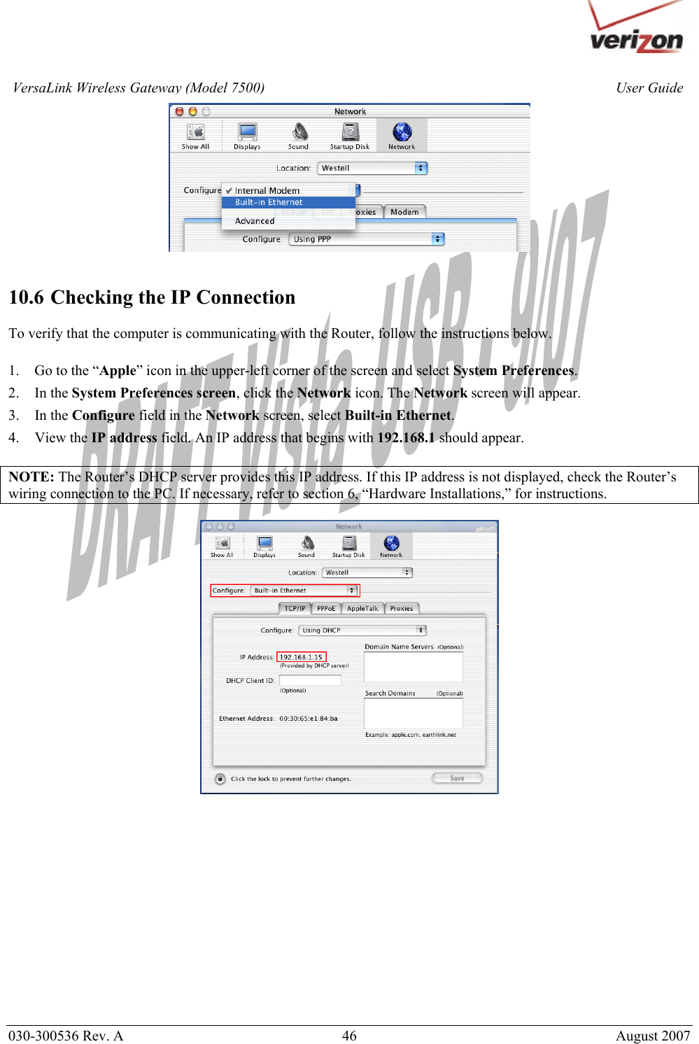
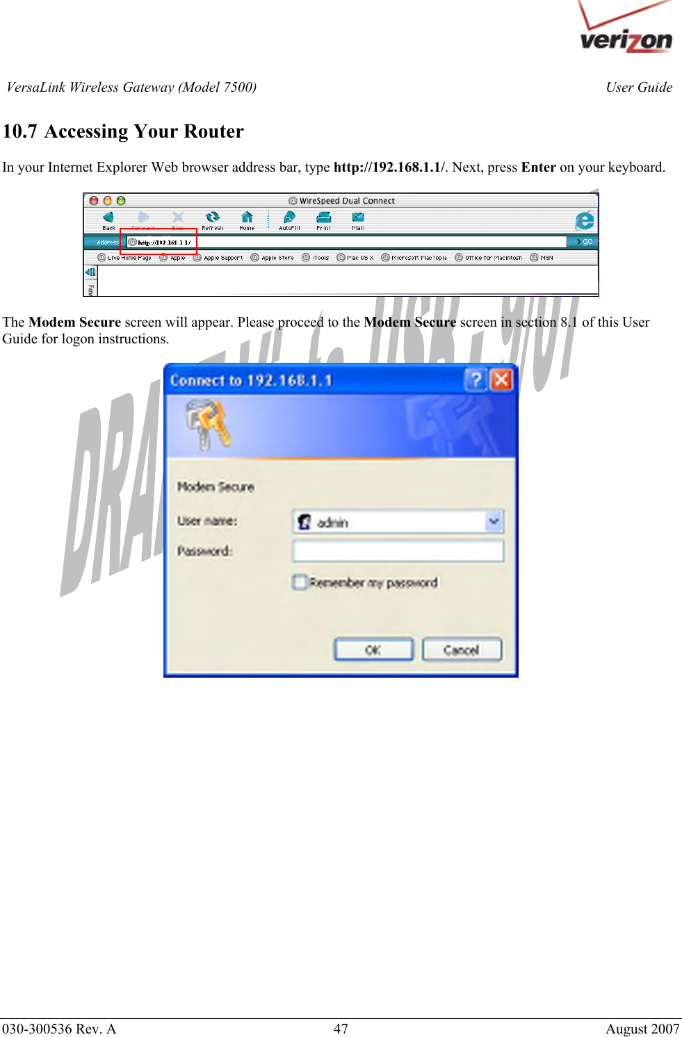
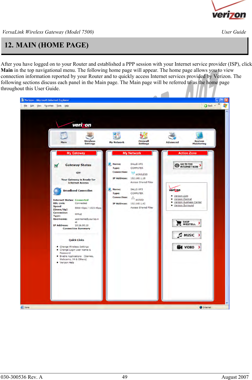
User Manual Part One

 030-300536 Rev. A  1       August 2007    VERSALINK™   WIRELESS GATEWAY (MODEL 7500) USER GUIDE
      030-300536 Rev. A  2       August 2007 User GuideVersaLink Wireless Gateway (Model 7500)CONTENTS  1. PRODUCT DESCRIPTION ..................................................................................................................................5 2. SAFETY INSTRUCTIONS ...................................................................................................................................5 3. REGULATORY INFORMATION ........................................................................................................................6 3.1 FCC Compliance Note...............................................................................................................................6 3.2 Canada Certification Notice.......................................................................................................................7 4. NETWORKING REQUIREMENTS .....................................................................................................................8 5. HARDWARE FEATURES....................................................................................................................................9 5.1 LED Indicators...........................................................................................................................................9 5.2 Cable Connectors and Switch Locations..................................................................................................10 5.3 Connector Descriptions............................................................................................................................10 5.4 Installation Requirements ........................................................................................................................11 5.5 Before you begin......................................................................................................................................11 5.6 Microfilters ..............................................................................................................................................11 6. HARDWARE INSTALLATIONS.......................................................................................................................12 7. INSTALLING THE USB DRIVERS...................................................................................................................17 7.1 Installing the USB Driver for Windows 98 SE........................................................................................17 7.2 Installing the USB Driver for Windows ME............................................................................................23 7.3 Installing the USB Driver for Windows 2000..........................................................................................25 7.4 Installing the USB Driver for Windows XP.............................................................................................28 7.5 Installing the USB Driver for Windows Vista™ .....................................................................................30 8. ACCESSING VERSALINK ................................................................................................................................31 8.1 Logging on to VersaLink .........................................................................................................................31 8.2 Changing the Password............................................................................................................................32 9. CONFIGURING YOUR BROADBAND CONNECTION .................................................................................35 9.1 Confirming Your DSL Connection..........................................................................................................35 9.2 Setting Up an Account Profile .................................................................................................................36 9.3 Connecting to the Internet........................................................................................................................41 9.4 Disconnecting from the Internet...............................................................................................................42 10. SETTING UP MACINTOSH OS X.....................................................................................................................44 10.1 Opening the System Preference Screen ...................................................................................................44 10.2 Choosing the Network Preferences..........................................................................................................44 10.3 Creating a New Location .........................................................................................................................45 10.4 Naming the New Location .......................................................................................................................45 10.5 Selecting the Ethernet Configuration.......................................................................................................45 10.6 Checking the IP Connection ....................................................................................................................46 10.7 Accessing Your Router ............................................................................................................................47 11. BASIC CONFIGURATION ................................................................................................................................48
      030-300536 Rev. A  3       August 2007 User GuideVersaLink Wireless Gateway (Model 7500)12. MAIN (HOME PAGE).........................................................................................................................................49 12.1 My Gateway Panel...................................................................................................................................50 12.2 My Network Panel ...................................................................................................................................50 12.3 Action Zone Panel....................................................................................................................................51 13. WIRELESS SETTINGS.......................................................................................................................................52 13.1 Wireless Status.........................................................................................................................................52 13.2 Simple Config..........................................................................................................................................53 13.3 Basic Security Settings ............................................................................................................................56 13.4 Advanced Security Settings .....................................................................................................................58 14. MY NETWORK...................................................................................................................................................70 14.1 Network Status.........................................................................................................................................70 14.2 Network Connections...............................................................................................................................74 15. FIREWALL SETTINGS ......................................................................................................................................95 15.1 General Firewall Security Settings...........................................................................................................95 15.2 Editing Firewall Security Rules ...............................................................................................................96 15.3 Port Forwarding .......................................................................................................................................98 15.4 DMZ Host—Single IP Address Passthrough.........................................................................................118 15.5 Remote Administration..........................................................................................................................123 15.6 Static NAT .............................................................................................................................................126 15.7 Security Log...........................................................................................................................................129 16. ADVANCED......................................................................................................................................................131 16.1 Diagnostics.............................................................................................................................................132 16.2 Restore Defaults.....................................................................................................................................135 16.3 Reboot Gateway.....................................................................................................................................136 16.4 Users ......................................................................................................................................................137 16.5 QOS .......................................................................................................................................................138 16.6 Remote Administration..........................................................................................................................139 16.7 ALG .......................................................................................................................................................140 16.8 Detect WAN Configuration ...................................................................................................................141 16.9 Dynamic DNS Configuration.................................................................................................................144 16.10 DNS Server............................................................................................................................................145 16.11 Configuration File..................................................................................................................................148 16.12 Firmware Upgrade .................................................................................................................................149 16.13 VPN .......................................................................................................................................................152 16.14 Universal Plug and Play.........................................................................................................................153 16.15 Time.......................................................................................................................................................154 16.16 Routing...................................................................................................................................................156
      030-300536 Rev. A  4       August 2007 User GuideVersaLink Wireless Gateway (Model 7500)16.17 IP Address Distribution..........................................................................................................................157 16.18 Private LAN—Configuring NAT ..........................................................................................................160 16.19 Public LAN—Multiple IP Address Passthrough ...................................................................................161 16.20 RIP Configuration..................................................................................................................................164 17. SYSTEM MONITORING..................................................................................................................................166 17.1 Gateway Status ......................................................................................................................................167 17.2 Advanced Status.....................................................................................................................................168 18. PORT FORWARDING SERVICES..................................................................................................................179 19. TECHNICAL SUPPORT INFORMATION ......................................................................................................183 20. PRODUCT SPECIFICATIONS.........................................................................................................................183 21. SOFTWARE LICENSE AGREEMENT............................................................................................................184 22. PUBLICATION INFORMATION.....................................................................................................................186
      030-300536 Rev. A  5       August 2007 User GuideVersaLink Wireless Gateway (Model 7500)1. PRODUCT DESCRIPTION   The Verizon® VersaLink™ Wireless Gateway provides reliable, high-speed, Internet access to your existing small office phone line and is capable of data rates hundreds of times faster than a traditional analog modem. But unlike analog modems, the VersaLink Gateway allows you to use the same phone line for simultaneous voice/fax communications and high-speed Internet access, eliminating the need for dedicated phone lines for voice and data needs. In addition, VersaLink supports a variety of networking interfaces such as Wireless 802.11b/g, ADSL, Ethernet and USB, along with the following optional features:  • UPLINK/E1: Alternate WAN uplink port • E4/DATA: Alternate Ethernet/USB connection • Layer w/2 QOS with VLAN tagging • HotSpot • Simultaneous public/private network support  Hereafter, the Verizon® VersaLink™ Wireless Gateway will be referred to as “VersaLink,” “Router,” or “Modem.”  2. SAFETY INSTRUCTIONS    • Never install any telephone wiring during a lightning storm. • Never install telephone jacks in wet locations unless the jack is specifically designed for wet locations. • Never touch non-insulated telephone wires or terminals unless the telephone line has been disconnected at the network interface. • Use caution when installing or modifying telephone lines.    WARNING   Risk of electric shock. Voltages up to 140 Vdc (with reference to ground) may be present on telecommunications circuits.
      030-300536 Rev. A  6       August 2007 User GuideVersaLink Wireless Gateway (Model 7500)3. REGULATORY INFORMATION   3.1 FCC Compliance Note   (FCC ID: CH87500XX-07)  This equipment has been tested and found to comply with the limits for a Class B digital device, pursuant to Part 15 of the Federal Communication Commission (FCC) Rules. These limits are designed to provide reasonable protection against harmful interference in a residential installation. This equipment generates, uses, and can radiate radio frequency energy, and if not installed and used in accordance with the instructions, may cause harmful interference to radio communications. However, there is no guarantee that interference will not occur in a particular installation. If this equipment does cause harmful interference to radio or television reception, which can be determined by turning the equipment OFF and ON, the user is encouraged to try to correct the interference by one or more of the following measures:  • Reorient or relocate the receiving antenna. • Increase the separation between the equipment and the receiver. • Connect the equipment to a different circuit from that to which the receiver is connected. • Consult the dealer or an experienced radio/TV technician for help. • This device complies with part 15 of the FCC Rules. Operation is subject to the following two conditions: (1) this device may not cause harmful interference, and (2) this device must accept any interference received, including interference that may cause undesired operation.  WARNING: While this device is in operation, a separation distance of at least 20 cm (8 inches) must be maintained between the radiating antenna and users exposed to the transmitter in order to meet the FCC RF exposure guidelines. Making changes to the antenna or the device is not permitted. Doing so may result in the installed system exceeding RF exposure requirements. This device must not be co-located or operated in conjunction with any other antenna or radio transmitter. Installers and end users must follow the installation instructions provided in this guide.  Modifications made to the product, unless expressly approved, could void the users’ rights to operate the equipment.  PART 68 – COMPLIANCE REGISTRATION  This equipment is designated to connect to the telephone network or premises wiring using a compatible modular jack that is Part 68 compliant. A FCC compliant telephone cord and modular plug is provided with the equipment. See the Installation Information section of this User Guide for details.   A plug and jack used to connect this equipment to the premises wiring and telephone network must comply with the applicable FCC Part 68 rules and requirements adopted by the ACTA. A compliant telephone cord and modular plug is provided with this product. It is designed to be connected to a compatible modular jack that is also compliant. See installation instruction for details.  If this terminal equipment (Model 7500) causes harm to the telephone network, the telephone company may request you to disconnect the equipment until the problem is resolved. The telephone company will notify you in advance if temporary discontinuance of service is required. If advance notification is not practical, the telephone company will notify you as soon as possible. You will be advised of your right to file a complaint with the FCC if you believe such action is necessary. If you experience trouble with this equipment (Model 7500), do not try to repair the equipment yourself. The equipment cannot be repaired in the field. Contact Verizon for instructions.
      030-300536 Rev. A  7       August 2007 User GuideVersaLink Wireless Gateway (Model 7500)The telephone company may make changes to their facilities, equipment, operations, or procedures that could affect the operation of this equipment. If this happens, the telephone company will provide advance notice in order for you to make the modifications necessary to maintain uninterrupted service.  If your home has specially wired alarm equipment connected to the telephone line, ensure that the installation of this equipment (Model 7500) does not disable your alarm equipment. If you have questions about what will disable alarm equipment, consult your telephone company or a qualified installer.  This equipment cannot be used on public coin phone service provided by the telephone company. Connection of this equipment to party line service is subject to state tariffs.  3.2 Canada Certification Notice  The Industry Canada label identifies certified equipment. This certification means that the equipment meets certain telecommunications network protective, operations and safety requirements as prescribed in the appropriate Terminal Equipment Technical Requirements document(s). The department does not guarantee the equipment will operate to the user’s satisfaction.  This equipment meets the applicable Industry Canada Terminal Equipment Technical Specification. This is confirmed by the registration number. The abbreviation, IC, before the registration number signifies that registration was performed based on a Declaration of Conformity indicating that Industry Canada technical specifications were met. It does not imply that Industry Canada approved the equipment. The Ringer Equivalence Number (REN) is 0.0. The Ringer Equivalence Number that is assigned to each piece of terminal equipment provides an indication of the maximum number of terminals allowed to be connected to a telephone interface. The termination on an interface may consist of any combination of devices subject only to the requirement that the sum of the Ringer Equivalence Numbers of all the devices does not exceed five.  Before installing this equipment, users should ensure that it is permissible to be connected to the facilities of the local Telecommunication Company. The equipment must also be installed using an acceptable method of connection. The customer should be aware that compliance with the above conditions may not prevent degradation of service in some situations. Connection to a party line service is subject to state tariffs. Contact the state public utility commission, public service commission, or corporation commission for information.  If your home has specially wired alarm equipment connected to the telephone line, ensure that the installation of this equipment (Model 7500) does not disable your alarm equipment. If you have questions about what will disable alarm equipment, consult your telephone company or a qualified installer.  If you experience trouble with this equipment (Model 7500), do not try to repair the equipment yourself. The equipment cannot be repaired in the field and must be returned to the manufacturer. Repairs to certified equipment should be coordinated by a representative, and designated by the supplier. Contact Verizon for instructions.   The termination on an interface may consist of any combination of devices subject only to the requirement that the sum of the Ringer Equivalence Numbers of all the devices does not exceed five.  Users should ensure, for their own protection, that the electrical ground connections of the power utility, telephone lines, and internal, metallic water pipe system, if present, are connected together. This precaution may be particularly important in rural areas.      CAUTION  Users should not attempt to make such connections themselves, but should contact the appropriate electrical inspection authority, or electrician, as appropriate.
      030-300536 Rev. A  8       August 2007 User GuideVersaLink Wireless Gateway (Model 7500)4. NETWORKING REQUIREMENTS   The following system specifications are required for optimum performance of the Router via 10/100 Base-T Ethernet or USB installations.  Connection Type  Minimum System Requirements ETHERNET    UPLINK/E1     E2     E3     E4/Data  • Pentium® or equivalent class machines or higher • Microsoft® Windows® (Vista™, XP, 2000, ME, NT 4.0, 98 SE) Macintosh® OS X, or Linux installed • 64 MB RAM (128 MB recommended) • 10 MB of free hard drive space • 10/100 Base-T Network Interface Card (NIC) • Internet Explorer 5.5 or later or Netscape Navigator 7.x or later • Computer Operating System CD-ROM on hand USB • Pentium® or equivalent class machines or higher • Microsoft® Windows® (Vista™, XP, 2000, ME, 98 SE) installed • 64 MB RAM (128 MB recommended) • 10 MB of free hard drive space • USB Version 1.1 or higher compliant bus • Internet Explorer 5.5 or higher or Netscape Navigator 7.x or later • Computer operating system CD-ROM WIRELESS IEEE 802.11b/g  • Pentium® or equivalent class or higher • Microsoft® Windows® (Vista™, XP, 2000, ME, NT 4.0, 98 SE) or Macintosh® OS X installed • 64 MB RAM (128 MB recommended) • 10 MB of free hard drive space • Internet Explorer 5.5 or Netscape Navigator 7.x or later • An available IEEE 802.11b/g PC adapter • Computer Operating System CD-ROM on hand
      030-300536 Rev. A  9       August 2007 User GuideVersaLink Wireless Gateway (Model 7500)5. HARDWARE FEATURES  5.1 LED Indicators  This section explains the LED States and Descriptions. LED indicators are used to verify the unit’s operation and status.   LED States and Descriptions  LED State  Description Solid Green  Router power is ON. OFF  Router power is OFF. POWER Solid Red POST (Power On Self Test), Failure (not bootable) or Device Malfunction. Note: The Power LED should be red no longer than two seconds after the power on self test passes. Solid Green Powered device is connected to the associated port (includes devices with wake-on LAN capability where slight voltage is supplied to an Ethernet connection). Note: When using the optional uplink port (E1), Ethernet LAN connection is limited to E2, E3, and E4. Flashing Green  10/100 Base-T LAN activity is present (traffic in either direction) E1, E2, E3, E4 (Ethernet LAN) OFF  Router power is OFF, no cable or no powered device is connected to the associated port. Solid Green  Link Established. Flashing Green  Wireless LAN activity is present (traffic in either direction). WIRELESS OFF  Router power is OFF or No Link. Solid Green  USB link established. Flashing Green  USB LAN activity present (traffic in either direction). USB OFF  No USB link established. Solid Green  Good DSL link. Flashing Green   DSL attempting to sync. Solid Amber  Modem is in safeboot mode. DSL OFF  Router power is OFF. Solid Green Internet link established. With DSL up, the Router has a WAN IP address from IPCP or DHCP; or a static IP is configured; or PPP negotiation has successfully completed (if used) and no traffic is detected. Flashing Green IP connection established and IP Traffic is passing through device (in either direction). Note: If the IP or PPP session is dropped due to an idle timeout, the light will remain solid green, if an ADSL connection is still present. If the session is dropped for any other reason, the light is turned OFF. The light will turn red when it attempts to reconnect and DHCP or PPP fails). Solid Red Device attempted to become IP connected and failed (no DHCP response, no PPP response, PPP authentication failed, no IP address from IPCP, etc.).  INTERNET OFF  Router power is OFF, Router is in Bridge Mode, or the ADSL connection is not present.
      030-300536 Rev. A  10       August 2007 User GuideVersaLink Wireless Gateway (Model 7500)5.2 Cable Connectors and Switch Locations  • DSL connector (RJ-11) • Reset push button • Four Ethernet (RJ-45) connectors with optional UPLINK/E1 port and optional E4/DATA port NOTE: 1. When using the optional UPLINK/E1 jack (when VersaLink is configured for WAN Uplink mode), Ethernet LAN connection is limited to ports E2, E3, and E4. The Uplink feature is optional. If Uplink is not enabled via the Web pages, VersaLink will use DSL as the WAN interface. 2. If you desire to install VersaLink via USB, use the optional E4/DATA port, which can be used for either USB or Ethernet installation. See section 6 for hardware installation instructions. • Power connector (12 VDC) barrel • OFF/ON power switch  VersaLink Gateway - Rear View       5.3 Connector Descriptions  The following chart displays the Router’s connector types.   NAME TYPE FUNCTION DSL LINE  Modular 6-pin (RJ-11) DSL jack  Connects the Router to a telephone jack that has active ADSL service or to the DSL port of a POTS splitter. UPLINK/E1  Modular 8-pin (RJ-45) Ethernet jack  Connects the Router to a PC or Hub via 10/100 BaseT Ethernet.  E2/E3/E3  Modular 8-pin (RJ-45) Ethernet jack Connects the Router to a PC or Hub via 10/100 BaseT Ethernet.  E4/DATA  Modular 8-pin (RJ-45) Ethernet jack Connects the Y-cable provided with the kit to the 10/100 Base-T Ethernet   DATA port on the rear of the Router and to the Ethernet port on a PC or Hub. The USB connector built in to the Y-cable also functions through the Router’s E4/DATA port. When the Ethernet connector is plugged in to the Router’s DATA port, the USB cable can then be plugged in to the USB port on a PC or Hub. Thus, the Y-cable provides Internet connectivity via Ethernet or USB; however, both connectors cannot be used sumultaneously. If both connectors are DSL Line Connector  Off/On   Power Switch Power Connector Ethernet Connectors (UPLINK/E1 E2, E3, E4/DATA)Reset Button
      030-300536 Rev. A  11       August 2007 User GuideVersaLink Wireless Gateway (Model 7500)installed in a PC or Hub at the same time, only the connector that syncs up first will be used.  POWER  Barrel connector  Connects the 12 VDC power connector to an AC wall jack.   5.4 Installation Requirements  This section explains the hardware installation procedures for installing your Router.  To install the VersaLink, you will need the following: • Active DSL line   • Network Interface Card (NIC) installed in your PC, or • Available USB port installed in your PC • 802.11 b/g wireless adapter installed in your PC  IMPORTANT: Please wait until you have received notification from your Internet service provider (ISP) that your DSL line has been activated before installing your VersaLink.  5.5 Before you begin  Make sure that your kit contains the following items:  • Verizon® ProLine™ Modem • Power Supply • Y-cable contains: o Built-in 10/100 BaseT Ethernet cable—labeled PC/Ethernet, yellow o Built-in USB cable—labeled PC/USB, blue • RJ-11 Phone cable • CD-ROM containing User Guide in PDF format   5.6 Microfilters  ADSL signals must be blocked from reaching each telephone, answering machine, fax machine, computer Modem or any similar conventional device. Failure to do so may degrade telephone voice quality and ADSL performance. Install a microfilter if you desire to use the DSL-equipped line jack for telephone, answering machine, fax machine or other telephone device connections. Microfilter installation requires no tools or telephone rewiring. Just unplug the telephone device from the baseboard or wall mount and snap in a microfilter, next snap in the telephone device. You can purchase microfilters from your local electronics retailer, or contact the original provider of your DSL equipment.
      030-300536 Rev. A  12       August 2007 User GuideVersaLink Wireless Gateway (Model 7500)6. HARDWARE INSTALLATIONS  The following instructions explain how to install your VersaLink Gateway using 10/100 Base-T Ethernet, Wireless,  Ethernet Uplink, or USB connections. Before you begin, please read the following notes:  NOTE: 1. If your Ethernet card does not auto-negotiate, set it to half duplex. Refer to the Ethernet card manufacturer’s instructions for installing and configuring your Ethernet card. 2. If you are using VersaLink in conjunction with an Ethernet Hub or Switch, refer to the manufacturer’s instructions for proper installation and configuration.  3. When using a Microfilter, confirm that the DSL RJ-11 phone cable is connected to the DSL port of the DSL/HPN non-filtered jack. 4. It is recommended that you use a surge suppressor to protect equipment attached to the power supply. Use only the power supply provided with your kit. 5. Additional Ethernet cables may be required depending on the installation method you are using. Ethernet cables and DSL filters can be purchased at your local computer hardware retailer. 6. VersaLink supports simultaneous use of 10/100 Base-T Ethernet and Wireless configurations. To use this installation method, follow the instructions provided in sections 6.1.1 and 6.1.2. VersaLink does not support simultaneous use of 10/100 Base-T Ethernet and USB connections.  VersaLink supports two modes for WAN access, which are configurable through VersaLink’s Web pages: (1) LAN Ethernet port mode and (2) WAN Uplink port mode.  • LAN Ethernet port mode allows you to use VersaLink’s DSL port for WAN access (VersaLink’s DSL functionality is Enabled). In this mode you should install VersaLink according to the instructions in the following sections:  • Section 6.1.1, Connecting VersaLink via 10/100 Base-T Ethernet • Section 6.1.2, Connecting VersaLink via Wireless • Section 6.1.4, Connecting VersaLink via USB • WAN Uplink port mode allows you to use VersaLink as an Ethernet Gateway (for example, to connect to a cable modem or to another ADSL device that provides WAN access). In WAN Uplink port mode, VersaLink’s DSL functionality is Disabled. In this mode you should install VersaLink according to the instructions in section 6.1.3, “Connecting VersaLink via UPLINK/E1.”
      030-300536 Rev. A  13       August 2007 User GuideVersaLink Wireless Gateway (Model 7500)6.1.1 Connecting VersaLink via 10/100 Base-T Ethernet   To connect your VersaLink using the 10/100-BaseT Ethernet connection, please follow these steps:  1. Connect the DSL phone cable from the connector marked DSL on the rear panel of the Modem to the DSL-equipped telephone line jack on the wall. Please use the DSL phone cable that was provided with your kit. IMPORTANT: Plug the RJ-11 DSL phone cable from the Router into the DSL port of the microfilter plugged into the telephone jack at the wall. 2. Use the Y-cable provided with your kit. Plug the Ethernet jack (labeled PC/Ethernet, yellow) into the Ethernet port on your computer. Then, at the other end of the Y-cable, plug the other Ethernet jack (labeled PC/Ethernet, yellow) into any of the four Ethernet connectors on the rear panel of the Router. NOTE: You can connect to any of the four Ethernet jacks on the rear panel of your Router as they serve as an Ethernet switch. However, when using the optional uplink port (labeled UPLINK/E1), Ethernet LAN connection is limited to ports E2, E3, and E4/DATA. 3. Connect the power supply cord to the power connector marked 12VDC on the rear panel of the Modem. Plug the other end of the power supply into an AC wall socket, and then turn on the Router (if it is not already on). 4. Check to see if the POWER LED is solid green. Solid green indicates that the Router is functioning properly. 5. Check to see if the DSL LED is solid green. If it is solid green, DSL is functioning properly. 6. Check to see if the ETHERNET LED is solid green. Solid green indicates that Ethernet is functioning properly. Check the ETHERNET LED for the Ethernet jack you are using on the VersaLink. 7. After you have logged on to your account and established an Internet connection, as explained later in section 9, check to see if the Modem’s INTERNET LED is solid green. Solid green indicates that the Internet link has been established. (Flashing green indicates the presence of IP traffic.)  Congratulations! You have completed the Ethernet hardware installation. No software installation is required when using only an Ethernet connection. Now proceed to section 8 to access VersaLink’s Web pages.    6.1.2 Connecting VersaLink via Wireless  IMPORTANT: If you are connecting to VersaLink via a wireless network adapter, the SSID must be the same for both VersaLink and your PC’s wireless network adapter. The default SSID for VersaLink is the serial number of the unit (located below the bar code on the bottom of the modem and also on the shipping carton). Locate and run the utility software provided with your PC’s Wireless network adapter and enter the SSID value. The PC’s wireless network adapter must be configured with the SSID (in order to communicate with VersaLink) before you begin the account setup and configuration procedures. Later, for privacy you can change the SSID by following the procedures outlined in section 13, “Wireless Settings.”  NOTE: Client PCs can use any Wireless 802.11b/g card to communicate with VersaLink. The Wireless card and VersaLink must use the same Wired Equivalent Privacy (WEP) security code type. The factory default for WEP is Enabled. Please be sure that your computer’s wireless adapter is configured properly for whichever network setting you use: WEP or WPA. You can access the settings in the advanced properties of the wireless network adapter.
      030-300536 Rev. A  14       August 2007 User GuideVersaLink Wireless Gateway (Model 7500)To network VersaLink to computers in your home or office using a wireless installation, you will need to confirm the following:  1. Ensure that each PC on your wireless network has an 802.11b/g wireless network adapter installed. 2. Ensure that appropriate drivers for your wireless adapter have been installed on each PC. 3. Connect the DSL phone cable from the connector marked DSL on the rear panel of VersaLink to the DSL-equipped telephone line jack on the wall. Please use the DSL phone cable that was provided with your kit. IMPORTANT: Plug the RJ-11 DSL phone cable from the Router into the DSL port of the microfilter plugged into the telephone jack at the wall. 4. Use the Y-cable provided with your kit. Plug the Ethernet jack (labeled PC/Ethernet, yellow) into the Ethernet port on your computer. Then, at the other end of the Y-cable, plug the other Ethernet jack (labeled PC/Ethernet, yellow) into any of the four Ethernet connectors on the rear panel of the Router. NOTE: You can connect to any of the four Ethernet jacks on the rear panel of your Router as they serve as an Ethernet switch. However, when using the optional uplink port (labeled UPLINK/E1), Ethernet LAN connection is limited to ports E2, E3, and E4/DATA. 5. Connect the power supply cord to the power connector marked 12VDC on the rear panel of the VersaLink. Plug the other end of the power supply into an AC wall socket, and then turn on VersaLink (if it is not already on). 6. Check to see if VersaLink’s POWER LED is solid green. This indicates that VersaLink is powered on. 7. Check to see if VersaLink’s DSL LED is solid Green. If it is solid Green, VersaLink is functioning properly.  8. Check to see if the ETHERNET LED is solid green. Solid green indicates that the Ethernet connection is functioning properly. Check the ETHERNET LED for the Ethernet jack you are using on the VersaLink. 9. Check to see if VersaLink’s WIRELESS LED is solid Green. This means that the Wireless interface is functioning properly. 10. After you have logged on to your account and established an Internet connection, as explained later in section 9, check to see if VersaLink’s INTERNET LED is solid green. Solid green indicates that an Internet link has been established. (Flashing green indicates the presence of IP traffic.)  Congratulations! You have completed the Wireless installation for VersaLink. Now proceed to section 8 to access VersaLink’s Web pages.
      030-300536 Rev. A  15       August 2007 User GuideVersaLink Wireless Gateway (Model 7500)6.1.3 Connecting VersaLink via UPLINK/E1  The Uplink feature is optional. If you want to install your Router so that it uplinks to another ADSL device, follow the steps outlined below:  1. Connect the attached ADSL device to the ADSL-equipped jack on the wall, using the RJ-11 phone cord that was provided with the kit. If you are using a microfilter at the wall jack, you must connect the RJ-11 DSL phone cable from the DSL port of the ADSL device to the DSL port of the microfilter. NOTE: The ADSL device to which you are connecting will function as your WAN interface to the Internet. Be sure you have connected the ADSL device appropriately. If needed, refer to the manufacturer’s instructions. 2. Use the Y-cable provided with your kit. Plug the Ethernet jack from the port marked UPLINK/E1 on the rear panel of VersaLink to the Ethernet port on the attached ADSL device, and then turn on the power switch of the attached ADSL device (if it is not already on). NOTE: Later, in VersaLink’s Web pages, be sure to select WAN Uplink port mode to allow VersaLink to uplink to the ADSL device. When VersaLink is configured for WAN Uplink port mode, VersaLink’s DSL transceiver will not be used. The ADSL device to which VersaLink is connected will be your WAN interface to the Internet. LAN Ethernet port is VersaLink’s factory default setting, refer to section 14.2.3 for details. 3. Connect additional PCs to VersaLink using the Ethernet jacks marked E2, E3, or E4/DATA on the rear panel of VersaLink; each jack serves as an Ethernet switch. (Additional Ethernet cables are not provided with the kit.) 4. Connect the power supply cord to the power connector marked 12VDC on the rear panel of the VersaLink. Plug the other end of the power supply into an AC wall socket, and then turn on the power (if it is not on). 5. Check to see if the VersaLink’s POWER LED is solid green. This indicates that VersaLink is powered on. 6. Check to see if the ETHERNET LED is solid green. Solid green indicates that the Ethernet connection is functioning properly. Check the ETHERNET LED for the Ethernet jack you are using on VersaLink. 7. After you have logged on to your account and established an Internet connection, as explained later in section 7, check to see if the VersaLink’s INTERNET LED is solid green. Solid green indicates that an Internet link has been established. (Flashing green indicates the presence of IP traffic.)  Congratulations! You have completed the UPLINK/E1 installation for VersaLink. No software installation is required when using the uplink connection. Now proceed to section 8 to access VersaLink’s Web pages.   6.1.4 Connecting VersaLink via USB  It is recommended that you connect your VersaLink via Ethernet connections. However, if you choose to connect your computer via USB, you must follow the instructions in this section.   IMPORTANT: The USB installation will not function for Macintosh computers. Macintosh users will need to install the Router via Ethernet connection. See section 6.1.1 for Ethernet installation instructions.  To install your Router using a USB connection, please follow these steps in the order presented:   1. Insert the CD-ROM provided with your kit into the CD-ROM drive of the PC that will connect via USB. 2. Use the Y-cable provided with your kit. At the “Y” end of the cable, plug the USB connector (labeled PC/USB, blue) into the USB port on your computer. Then, at the other end of the Y-cable, plug the Ethernet jack (labeled PC/Ethernet, yellow) into the Ethernet connector marked E4/DATA on the rear panel of the Router.  3. Connect the power supply cord to the power connector marked 12VDC on the rear panel of the Router. Plug the other end of the power supply into an AC wall socket, and then turn on the Router (if it is not already on).
      030-300536 Rev. A  16       August 2007 User GuideVersaLink Wireless Gateway (Model 7500)4. Complete the instructions outlined in section 7, “Installing the USB Drivers.” Then, return to this section to complete the remaining steps. 5. Connect the DSL phone cable from the connector marked DSL on the rear panel of the Modem to the DSL-equipped telephone line jack on the wall. Please use the DSL phone cable that was provided with your kit. IMPORTANT: Plug the RJ-11 DSL phone cable from the Router into the DSL port of the microfilter plugged into the telephone jack at the wall. 6. Check to see if the POWER LED is solid green. This indicates that VersaLink is powered on. 7. Check to see if the DSL LED is solid green. If it is, DSL is functioning properly 8. After the USB drivers have been installed, check to see if the USB LED is solid green. Solid green indicates that the USB connection is functioning properly. 9. After you have logged on to you account and established an Internet connection, as explained later in section 9, check to see if the Modem’s INTERNET LED is solid green. Solid green indicates that the Internet link has been established. (Flashing green indicates the presence of IP traffic.)  Congratulations! You have completed the USB hardware installation. Now proceed to section 8 to access VersaLink’s Web pages.
      030-300536 Rev. A  17       August 2007 User GuideVersaLink Wireless Gateway (Model 7500)7. INSTALLING THE USB DRIVERS  This section explains how to install the USB drivers for your Router. If you are using only an Ethernet connection, USB driver installation is not necessary. The Microsoft Plug and Play auto-detect feature recognizes when new hardware has been installed. After you connect the Router to the PC, the Router will be detected automatically.  IMPORTANT: Make sure that the CD-ROM provided with your kit is inserted into the PC’s CD-ROM drive before you connect the blue USB cable to the Router and the PC, as explained in section 6.1.4, “Connecting VersaLink via USB.”  Determine which operating system is installed on your PC, and then follow the USB driver instructions that match your operating system. The following table provides a reference to the USB driver installation instructions. After you have completed the USB driver installation, return to section 6.1.4 to complete the USB hardware installation instructions.   Your Operating System Refer to this section for USB driver instructions Windows 98 SE  7.1 Installing the USB Driver for Windows 98 SE Windows ME  7.2 Installing the USB Driver for Windows ME Windows 2000  7.3 Installing the USB Driver for Windows 2000 Windows XP  7.4 Installing the USB Driver for Windows XP Windows Vista™  7.5 Installing the USB Driver for Windows Vista™   7.1  Installing the USB Driver for Windows 98 SE  IMPORTANT: Confirm that the CD-ROM provided with the Router kit is inserted into the PC’s CD-ROM drive before beginning this installation.   1. Windows 98 SE: After you connect the Router to your PC, the Found New Hardware window will appear (Figure 1). After a brief delay, the Add New Hardware Wizard window will appear (Figure 2) Click Next.   Figure 1. Windows 98 SE
      030-300536 Rev. A  18       August 2007 User GuideVersaLink Wireless Gateway (Model 7500)   Figure 2. Windows 98 SE  2. Windows 98 SE:  Select Search for the best driver for your device. (Recommended). See Figure 3. Click Next.     Figure 3.  Windows 98 SE
      030-300536 Rev. A  19       August 2007 User GuideVersaLink Wireless Gateway (Model 7500)  3. Windows 98 SE:  Select CD-ROM drive (Figure 4). Click Next. Windows will search for the driver.   Figure 4.  Windows 98 SE  Note: If Figure 4 does not appear at this step, and Figure 5 appears with the text ‘USB Composite device’, ‘C:\Windows\Inf\USB.Inf’, do not continue. Click Back to Step 3 and specify the location of the CD-ROM.   4. Windows 98 SE: Select The updated driver (Recommended) Westell USB Network Interface (Figure 5). Click Next.   Figure 5.  Windows 98 SE
      030-300536 Rev. A  20       August 2007 User GuideVersaLink Wireless Gateway (Model 7500)   5. Windows 98 SE: Windows will display the location of the driver (Figure 6). The drive “letter” may vary. Click Next.   Figure 6.  Windows 98 SE  6. Windows 98 SE: Remove the CD from the CD-ROM Drive. Next, insert the Windows operating system CD into the CD-ROM Drive (Figure 7). Click OK.   Figure 7.  Windows 98 SE  7. Windows 98 SE: The system will begin copying files (Figure 8).   Figure 8.  Windows 98 SE
      030-300536 Rev. A  21       August 2007 User GuideVersaLink Wireless Gateway (Model 7500) 8. Windows 98 SE: Figure 9 may pop up, depending on how Windows 98 SE was installed on the computer. The installation of the Router requires files that are supplied by Microsoft for Windows 98 SE. If Figure 10 pops up, insert the Windows 98 SE Operating System CD into the computers CD-ROM drive, wait a moment for the CD to be recognized by the system, and then click on OK. The system should find the required files on the Windows 98 SE CD-ROM and automatically complete the installation.   Figure 9.  Windows 98 SE If the Operating System CD is not available, or if Figure 9 pops up again, you will have to manually specify the location of the files. The required files may be stored on your hard drive. A common location for these files is "C:\Windows\Options\Cabs." Try specifying this path or the path to your CD-ROM drive (usually "D:\") by clicking the Browse… button in the Insert Disk screen (Figure 10). When you have specified the correct path, click on OK. The system will begin copying the files.  IMPORTANT: It is very important that the Windows 98 SE files be installed. Do not click on Cancel or Skip File in the dialogs; doing so will result in an improper installation, and the Router will not function correctly.   Figure 10. Windows 98 SE
      030-300536 Rev. A  22       August 2007 User GuideVersaLink Wireless Gateway (Model 7500)  9. Windows 98 SE: The window below confirms that the PC has finished loading the drivers (Figure 11). Click Finish.   Figure 11.  Windows 98 SE  10. Windows 98 SE: Click Yes to restart your computer (Figure 12).   Figure 12.  Windows 98 SE  Congratulations! You have completed the software installation for the USB drivers. Now return to section 6.1.4, “Connecting VersaLink via USB,” to complete the hardware installation instructions.
      030-300536 Rev. A  23       August 2007 User GuideVersaLink Wireless Gateway (Model 7500) 7.2 Installing the USB Driver for Windows ME  IMPORTANT: Confirm that the CD-ROM provided with the Router kit is inserted into the PC’s CD-ROM drive before beginning this installation.   1. Windows ME: After you connect the Router to your PC, the Found New Hardware window will appear (Figure 13). After a brief delay, the Add New Hardware Wizard will appear (Figure 14). Select Automatic search for a better driver (Recommended). Click Next.   Figure 13.  Windows ME   Figure 14.  Windows ME
      030-300536 Rev. A  24       August 2007 User GuideVersaLink Wireless Gateway (Model 7500)  2. Windows ME: Windows will display the location of the driver (Figure 15). Click Next.   Figure 15.  Windows ME  3. Windows ME: The window below confirms that the PC has finished loading the drivers (Figure 16). Click Finish.    Figure 16.  Windows ME
      030-300536 Rev. A  25       August 2007 User GuideVersaLink Wireless Gateway (Model 7500) 4. Windows ME: When the System Settings Change screen appears, the USB drivers are installed properly (Figure 17). Click Yes.   Figure 17. Windows ME  Congratulations! You have completed the software installation for the USB drivers. Now return to section 6.1.4, “Connecting VersaLink via USB,” to complete the hardware installation instructions.  7.3 Installing the USB Driver for Windows 2000   IMPORTANT: Confirm that the CD-ROM provided with the Router kit is inserted into the PC’s CD-ROM drive before beginning this installation.   1. Windows 2000: After you connect the Router to your PC, the Found New Hardware window will appear (Figure 18). After a brief delay, the Found New Hardware Wizard will appear (Figure 19). Click Next.    Figure 18. Windows 2000   Figure 19. Windows 2000
      030-300536 Rev. A  26       August 2007 User GuideVersaLink Wireless Gateway (Model 7500)  2. Windows 2000: The Install Hardware Device Drivers window appears (Figure 20). Select Search for a suitable driver for my device (recommended). Click Next.   Figure 20.  Windows 2000   3. Windows 2000: The Locate Driver Files window appears. Select CD-ROM drives (Figure 21). Click Next.   Figure 21.  Windows 2000
      030-300536 Rev. A  27       August 2007 User GuideVersaLink Wireless Gateway (Model 7500)  4. Windows 2000: The Driver Files Search Results window appears (Figure 22). Note: The drive “letter” may vary. Click Next.   Figure 22.  Windows 2000  5. Windows 2000: The window below confirms that the PC has finished loading the drivers (Figure 23). Click Finish.   Figure 23.   Windows 2000
      030-300536 Rev. A  28       August 2007 User GuideVersaLink Wireless Gateway (Model 7500)  6. Windows 2000: When the System Settings Change screen appears, the USB drivers are installed properly (Figure 24). Click Yes.   Figure 24. Windows 2000  Congratulations! You have completed the software installation for the USB drivers. Now return to section 6.1.4, “Connecting VersaLink via USB,” to complete the hardware installation instructions.   7.4 Installing the USB Driver for Windows XP   IMPORTANT: Confirm that the CD-ROM provided with the Router kit is inserted into the PC’s CD-ROM drive before beginning this installation.   1. Windows XP: After you connect the Router to your PC, the following screen will appear. (Figure 25). Select Install the software automatically (Recommended). Click Next.    Figure 25. Windows XP
      030-300536 Rev. A  29       August 2007 User GuideVersaLink Wireless Gateway (Model 7500)   2. Windows XP: The window below confirms that the PC has finished loading the drivers (Figure 26). Click Finish.   Figure 26.  Windows XP  Congratulations! You have completed the software installation for the USB drivers. Now return to section 6.1.4, “Connecting VersaLink via USB,” to complete the hardware installation instructions.
      030-300536 Rev. A  30       August 2007 User GuideVersaLink Wireless Gateway (Model 7500) 7.5 Installing the USB Driver for Windows Vista™  IMPORTANT: Confirm that the CD-ROM provided with the Router kit is inserted into the PC’s CD-ROM drive before beginning this installation.   1. Windows Vista™: After you connect the Router to your PC, the following Found New Hardware screen will appear (Figure 27). Click Next.    Figure 27.  Windows Vista  2. Windows Vista™: The window below confirms that the PC has finished loading the drivers (Figure 28). Click Close.   Figure 28.  Windows Vista  Congratulations! You have completed the software installation for the USB drivers. Now return to section 6.1.4, “Connecting VersaLink via USB,” to complete the hardware installation instructions.
      030-300536 Rev. A  31       August 2007 User GuideVersaLink Wireless Gateway (Model 7500)8. ACCESSING VERSALINK   8.1 Logging on to VersaLink  This section explains the logon procedures for your VersaLink. This procedure should be used any time you want to access or make changes to VersaLink’s configurations or firewall settings.  IMPORTANT: VersaLink is capable of automatically sensing protocol type (DHCP or PPPoE). This process is designed to start after you have connected VersaLink. To access VersaLink, your PC must be configured for DHCP. Refer to your Windows help screen for information on configuring your computer for DHCP. At your PC, click Start, then Help to access the Windows help screen.  To log on to VersaLink, start your Web browser and type the following IP address in the browser’s address bar:   http://192.168.1.1   After you type the IP address, press Enter on your keyboard. The following Modem Secure screen will appear. Type the default user name (which is admin) and the default password (which is password) in the fields provided. Click OK.  NOTE: Hereafter, the VersaLink Wireless Gateway will be referred to as the “Router” or “Modem.”             adminpassword
      030-300536 Rev. A  32       August 2007 User GuideVersaLink Wireless Gateway (Model 7500) 8.2 Changing the Password  After you have clicked OK in the Modem Secure screen, the following User Settings screen will appear. This screen allows you to change the default administrator name and password to the values of your choice. The password change is required to continue your network logon. If the Router is password protected and you are not an authorized user, you will not be able to change the values in this screen. The Router cannot be configured unless an authorized user is logged in. If necessary, contact your network administrator for further instructions.  IMPORTANT:   1. The User Settings screen allows you to use admin as your administrator name (your administrator name can match your user name). However, this screen does not allow you to use “password” as your administrator password. If you enter password in the fields, this screen will not continue the logon. You must enter a different password in order for this screen to take effect. The values in these fields are case sensitive. Once you decide on an administrator name and password, please record them for future reference.  2. This feature changes the Administrator’s password, not the PPP password.  Type your administrator User Name and Password in the fields provided. The password fields will be masked for security purposes.              Type admin or the name of your choice. Type a new password. (Do not type the word password here.)
      030-300536 Rev. A  33       August 2007 User GuideVersaLink Wireless Gateway (Model 7500) After you have entered the desired values, click Apply.    If you clicked Apply, the following pop-up screen will appear. Click OK to allow the changes to take effect.
      030-300536 Rev. A  34       August 2007 User GuideVersaLink Wireless Gateway (Model 7500)If you clicked OK in the pop-up screen, the following screen will appear. This is the main page of your Router’s Web pages, also referred to in this document as the home page. You can access this page by clicking Main in the navigational menu located across the top of the Router’s Web pages. Details on this page will be explained in the following sections.
      030-300536 Rev. A  35       August 2007 User GuideVersaLink Wireless Gateway (Model 7500)9. CONFIGURING YOUR BROADBAND CONNECTION   To browse the Internet using your Router, you must confirm your DSL connection, set up your account profile, and establish a DHCP or PPP session with your Internet service provider (ISP). The procedures for configuring your Router’s connection settings are explained in this section.   9.1 Confirming Your DSL Connection  After you have logged on to the Router and changed your administrator password, as explained in section 8, the following home page will appear. Use this page to determine the status of your DSL and Internet connections.  IMPORTANT: You must have active DSL service before the Router can synchronize with Verizon’s equipment.   To determine if the Router has established a DSL link, do any of the following:  • In the My Modem panel of the Main page, view the DSL link field. If the status reads Not Connected, you do not have a DSL link. However, if DSL Link field displays Connected and the Speed (Down/Up) field displays numeric values, a DSL link has been established. The values displayed represent the transmission rates of your DSL signal, downstream and upstream. (You may need to wait a brief moment for the Router to report these values.) • At the front of the Router, check to see if the Router’s DSL LED is solid green. Solid green indicates that the Router’s DSL connection has been established. (The DSL LED may flash while the connection is being established.) Please wait a brief moment for the Router to connect.
      030-300536 Rev. A  36       August 2007 User GuideVersaLink Wireless Gateway (Model 7500)After confirming your DSL link, DHCP customers can now browse the Internet. However, PPP customers will need to complete further instructions, as explained in the following note.  NOTE: If the Router has established a DSL link and if you are connecting to the Internet via DHCP, you can now browse the Internet by following the instructions provided by Verizon. However, if you are connecting to the Internet via PPP, please proceed to section 9.2 to configure your Router’s broadband connection settings. After you have configured the broadband settings and connected to the Internet, view the My Modem panel; the Internet Status field will display Connected.     9.2 Setting Up an Account Profile  Your account profile is used to identify you to Verizon. To begin your account setup, go to the My Modem panel in the home page. Next, click the Not Connected link.  NOTE: Before you set up your account profile, obtain your Account ID and Account Password from Verizon. You will use this information when you set up your account parameters.
      030-300536 Rev. A  37       August 2007 User GuideVersaLink Wireless Gateway (Model 7500)If you clicked Not Connected in the preceding screen, the following pop-up screen will prompt you for a user name and password. Enter the User name and Password you used in the User Settings screen, in section 8.2, and then click OK to continue.    If you clicked OK, the following DSL Connection screen will appear. This screen displays information about your Internet connection and allows you to access the Router’s connection settings. If you have not set up your account profile, the PPP Status field will display Down, indicating that you have not established an Internet connection with Verizon.   Throughout this User Guide, the following icons are used to indicate clicking actions that you can take with your mouse to configure the Router’s settings.  Icon Description  Details/Edit Clicking this icon allows you to either view the details of or edit your Router’s settings.  Add/New Clicking this icon allows you to add new entries your Router.  Delete Clicking this icon allows you to delete an entry from your Router.  Expand Clicking this icon allows you to expand the page to view additional entries.  Collapse Clicking this icon allows you to collapse the page.  Connect Clicking this icon allows you to connect to Verizon   Disconnect Clicking this icon allows you to disconnect from Verizon.             Enter the name you used in the User Settings screen. Enter the password you used in the User Settings screen.
      030-300536 Rev. A  38       August 2007 User GuideVersaLink Wireless Gateway (Model 7500) To set up your account profile. Click the Edit   icon.    • Connection Name: The name of the connection profile your are using for your Internet connection. • Default: The name of the default profile that is used when the Router auto connects to the ISP. • PPP Status: The status of the PPP connection. Down = no PPP connection, Up = PPP connection is established. • Action: Click the icon in the Action column to connect to Verizon or to disconnect from Verizon (end your PPP session). If you end your PPP session, this does not end your DSL connection. • Add: Click the Add link to add additional profiles to your Router. • Edit: Click the Edit icon for My Connection to set up your connection profile. My Connection is the name of the default connection profile that you will use to connect to Verizon. Then, if you want, you can click Add to add additional connection profiles, and assign one as your default profile.  If you clicked Edit in the preceding screen, the following Edit Connection Profile screen will appear. Type your account parameters in the fields provided. The following account parameters are required for your Internet connection:  • Connection Name: The Connection Name is a word or phrase that you use to identify your account.  • Account ID: The Account ID is provided by Verizon • Account Password: The Account Password is provided by Verizon.
      030-300536 Rev. A  39       August 2007 User GuideVersaLink Wireless Gateway (Model 7500)    Next, select the connection type (Manual, On Demand, Always On) that you want to use for your default connection profile.   • Manual: Select this option if you want to manually establish your PPP session. • On Demand: Select this option if you want the Router to automatically reestablish your PPP session on demand anytime your PC requests Internet activity (for example, browsing the Internet, email, etc.). Please note that when you have Internet traffic, this setting may cause a delay. • Always On: Select this option if you want the Router to automatically establish a PPP session when you log on or if the PPP session goes down. The Router’s factory default setting is Always On.  If you enable the Router’s timeout feature, the Router will end the PPP session upon reaching the number of minutes you specify for connection timeout. To configure connection timeout, do the following:  1. In the Connection Type field, select either Manual or On Demand as the connection setting. NOTE: The Time Out Enable feature does not apply to Always On, only to On Demand and Manual, and the timeout option will be dimmed if you select Always On. The Router’s default connection type is Always On. 2. Next, click the Time Out Enable check box (a check mark will appear in the box). 3. Type the number of minutes in the Minutes for Connection Time Out box.
      030-300536 Rev. A  40       August 2007 User GuideVersaLink Wireless Gateway (Model 7500) To save your account password, in the Save Password field, click the top option. Clicking this option allows the Router to make a PPP connection without first prompting you for a password. (By default this option is already selected; the Router will automatically save the account password.) If you want the Router to prompt you for the account password, select Manual as the connection type, and then click the bottom option in the Save Password field. (The Router will prompt you for a password only if you have selected Manual as the connection type.)  After you have entered the appropriate settings in the Edit Connection Profile screen, click Apply to allow the settings to take effect. The following DSL Connection screen will appear.
      030-300536 Rev. A  41       August 2007 User GuideVersaLink Wireless Gateway (Model 7500) 9.3 Connecting to the Internet  After you have set up your account profile using the steps explained in section 9.2, you are ready to establish a PPP session (Internet connection) with Verizon. View the DSL Connection screen. If the PPP Status field displays Down, you do not have an Internet connection established. To establish an Internet connection, click connect. The PPP Status field will briefly display connecting; this means that the Router is establishing a PPP session. After Router’s establishes a PPP session, the PPP Status field will display Up. Congratulations! You can now browse the Internet.  NOTE: Whenever the PPP Status displays Down, you do not have a PPP session established. If your Router’s connection setting is set to Always On or On Demand, after a brief delay the PPP session will be established automatically, and PPP Status will display Up. However, if the connection setting is set to Manual, you must click the connect button to establish a PPP session. Once the PPP session has been established (PPP Status displays Up), you can browse the Internet.
      030-300536 Rev. A  42       August 2007 User GuideVersaLink Wireless Gateway (Model 7500)9.4 Disconnecting from the Internet  If you have finished browsing the Internet and want to disconnect from your Internet service provider, from the My Modem panel in the home page, click the connected link (next to Internet Status). The following DSL Connection screen will appear. Click disconnect to end your PPP session.    If you clicked disconnect, the following pop-up screen will appear. Click OK to continue.  IMPORTANT: If you disconnect the PPP session, this will disconnect the Router from the Internet, and Internet access for any device connected to your LAN will be unavailable until the PPP session is reestablished.
      030-300536 Rev. A  43       August 2007 User GuideVersaLink Wireless Gateway (Model 7500)If you clicked OK to disconnect your PPP session, after a brief moment, the PPP Status in the DSL Connection screen should display Down.   Also, at the home page in the My Modem panel, the Internet Status field will display Not Connected. Although your Internet connection is down, your DSL session will not be affected. When you are ready to end your DSL session, simply turn off the Router via the power switch on the Router’s rear panel.     NOTE:  When you are ready to exit the Router’s interface, click the X (close) in the upper-right corner of the window. Closing the window will not affect your PPP Status (your PPP session will not be disconnected) or your DSL connection. You must click the disconnect button to disconnect your PPP session. When you are ready to restore the Router’s interface, start your Internet browser, and then type http://192.168.1.1 in the browser’s address bar. Next, press Enter on your keyboard.
      030-300536 Rev. A  44       August 2007 User GuideVersaLink Wireless Gateway (Model 7500)10. SETTING UP MACINTOSH OS X   This section provides instructions on how to use Macintosh Operating System 10 with the Router. Follow the instructions in this section to create a new network configuration for Macintosh OS X.  NOTE: Macintosh computers must use the Router’s Ethernet installation. Refer to section 6 “Hardware Installations,” for details.   10.1 Opening the System Preference Screen  After you have connected the Router to the Ethernet port of your Macintosh, the screen below will appear. Click the “Apple” icon in the upper-left corner of the screen and select System Preferences.      10.2 Choosing the Network Preferences  After selecting System Preferences from the previous screen, the following screen will appear. Click the Network icon.
      030-300536 Rev. A  45       August 2007 User GuideVersaLink Wireless Gateway (Model 7500) 10.3 Creating a New Location  After clicking the Network icon, the Network screen will appear. Select New Location from the Location field.     10.4 Naming the New Location  After selecting New Location in the Network screen, the following screen will appear. In the field labeled Name your new location:, change the text from “Untitled” to “Westell.” Click OK.     10.5 Selecting the Ethernet Configuration  After clicking OK in the preceding screen, the Network screen will appear. The Network screen shows the settings for the newly created location. From the Configure field in the Network screen, select Built-in Ethernet. Click Save to save the settings.  NOTE: Default settings for the Built-in Ethernet configuration are sufficient to operate the Router.
      030-300536 Rev. A  46       August 2007 User GuideVersaLink Wireless Gateway (Model 7500)   10.6 Checking the IP Connection  To verify that the computer is communicating with the Router, follow the instructions below.  1. Go to the “Apple” icon in the upper-left corner of the screen and select System Preferences. 2. In the System Preferences screen, click the Network icon. The Network screen will appear. 3. In the Configure field in the Network screen, select Built-in Ethernet. 4. View the IP address field. An IP address that begins with 192.168.1 should appear.  NOTE: The Router’s DHCP server provides this IP address. If this IP address is not displayed, check the Router’s wiring connection to the PC. If necessary, refer to section 6, “Hardware Installations,” for instructions.
      030-300536 Rev. A  47       August 2007 User GuideVersaLink Wireless Gateway (Model 7500) 10.7 Accessing Your Router  In your Internet Explorer Web browser address bar, type http://192.168.1.1/. Next, press Enter on your keyboard.     The Modem Secure screen will appear. Please proceed to the Modem Secure screen in section 8.1 of this User Guide for logon instructions.
      030-300536 Rev. A  48       August 2007 User GuideVersaLink Wireless Gateway (Model 7500)11. BASIC CONFIGURATION  IMPORTANT: The following sections assume that you have active DSL and Internet service.  VersaLink allows you to make changes to the configurable features of your Router such as account profiles, routing configurations, and firewall settings. The following sections explain each feature and show you how to make changes to the Router’s settings. The navigational menu displayed at the top of each page allows you to navigate to the various configuration screens of your Router. Whenever you change the configurable settings of your Router, you must click Apply (or Save where applicable) to allow the changes to take effect in the Router.   NOTE: If you need help, go to the Quick Links section in the home page and then click Verizon Help. Clicking this link takes you to Verizon’s OnLine Help site where you can find additional information about your DSL Router.   To configure the basic settings in your Router, follow the instructions provided in sections 12 through 15.  NOTE: The menu options displayed will vary according to the configuration you have chosen to use: LAN Ethernet port or WAN Uplink port. If you are using WAN Uplink port, some menu options will not be available. However, all menu options will be available when the Router is configured for LAN Ethernet port. Instructions on enabling and disabling LAN Ethernet port and WAN Uplink port are explained in the section 14.2.3, “Configuring VersaPort.” This document was created with the Router configured for LAN Ethernet port mode.
      030-300536 Rev. A  49       August 2007 User GuideVersaLink Wireless Gateway (Model 7500)12. MAIN (HOME PAGE)  After you have logged on to your Router and established a PPP session with your Internet service provider (ISP), click Main in the top navigational menu. The following home page will appear. The home page allows you to view connection information reported by your Router and to quickly access Internet services provided by Verizon. The following sections discuss each panel in the Main page. The Main page will be referred to as the home page throughout this User Guide.
      030-300536 Rev. A  50       August 2007 User GuideVersaLink Wireless Gateway (Model 7500) 12.1 My Gateway Panel  In the home page, the My Modem panel allows you to view details about your Router’s connections and to access the connection settings in your Router. A green check mark displayed in the Modem Status check box signals you to Go! You can now browse the Internet. The Quick Links section allows you to quickly access Help information related to your Router and information on your Router’s configurable settings. The following details are displayed in the My Modem panel.  My Modem Internet Status  This field displays status of your Internet connection. Click this link to set up new account profiles, edit existing account profiles, and connect to or disconnect from Verizon. Additional details about your Router’s broadband connection can be found in section 9.2, “Setting Up an Account Profile,” of this User Guide. DSL Link   This field allows you to view the status of your DSL connection. Speed (Down/Up)  This field displays the transmission rates (in Kbits/sec) of your DSL signal. Down is the rate at which data is transmitted downstream (from the Internet to your computer). Up is the rate at which data is transmitted upstream (from your computer to the Internet). Connection Type  This field displays the protocol used for your Internet connection, provided by Verizon.  Username   This field displays the username that you used to connect to Verizon. The username and password are provided by Verizon. Internet IP Address  This is a WAN IP address that has been assigned to your Router by Verizon. You will receive the WAN IP address only after your Router has established an Internet connection with Verizon. (The LAN IP address of your Router is “192.168.1.1” which is assigned to your Router by factory default.) Change Wireless Settings  Click this link to change the Router’s wireless settings. Change Login User Name & Password Click this link to change the administrator user name and password. Enable Applications (games, webcams, IM, etc.) Click this link to set up a service profile and attach VPN, Gaming, or other NAT services to the profile. Verizon Help  Click this link to access Verizon’s Online Help where you can obtain detailed information about your Router.   12.2 My Network Panel   In the home page, the My Network panel allows you to view information about devices that are connected to your network. If your network provides access to shared files, you can access the files by clicking the Access Shared Files link. The following details are displayed in the My Network panel.  My Network Computer Name  The ASCII (text) name of the device connected network Connection Type   The physical connection used to interface with your Router. IP Address   The IP address assigned to your computer by your Router’s DHCP server. Access Shared Files   Click this link to access shared files from a device on your local network. (The device must have file sharing enabled.) Note: If the device has a firewall turned on, you will not be able to access shared file from the device.
      030-300536 Rev. A  51       August 2007 User GuideVersaLink Wireless Gateway (Model 7500) 12.3 Action Zone Panel  In the home page, the Action Zone panel allows quick access to Internet services provided by Verizon. The following details are displayed in the Action Zone panel.  NOTE: The links displayed in the Action Zone panel are specific to the services offered by Verizon and will be available only after you have established a PPP session (Internet connection) with Verizon.  Action Zone Go to the Internet Now Click this button to go to the default page of your Web browser. (Clicking this button will take you to the browser’s default page. However, if your PPP session is down, you do not have Internet access. To browse the Internet, you must first establish a PPP session with Verizon.) When you are ready to return to the Router’s Web interface, type http://192.168.1.1/ in your Internet browser’s address bar, and press Enter on your keyboard. Verizon   Click the links in this section to access networking services provides by Verizon. Shop Westell  Click this button to go to Westell’s home page. Music  Click this button to go to the Verizon Surround - Music page. Video  Click this button to go to the Verizon Surround - Movies page.
      030-300536 Rev. A  52       August 2007 User GuideVersaLink Wireless Gateway (Model 7500)13. WIRELESS SETTINGS  This section explains the wireless features of your Router and guides you through the configurable settings.  13.1 Wireless Status  If you select Wireless Settings from the top navigational menu and then select Wireless Status in the submenu options at the left of the screen, the following screen will appear. At this screen, you can view your Router’s wireless connection settings.
      030-300536 Rev. A  53       August 2007 User GuideVersaLink Wireless Gateway (Model 7500)13.2 Simple Config  If you select Wireless Settings from the top navigational menu and then select Simple Config in the submenu options at the left of the screen, the following screen will appear. Simple Config allows you to configure wireless access to your Router. Devices that support Wi-Fi protected setup can quickly connect to your Router using the Router’s simple config button, without first requesting long keywords or passphrases. By default, this feature is disabled in the Router.  Simple Config offers two methods for quick wireless connection to your Router.  • Push Button method: Clicking this option allows you to press a button on the Router and on the client (usually a software button) to automatically setup secure wireless access to the Router.  • PIN entry method: Clicking this option allows you to enter a PIN code, generated by the client (PC, Wireless Printer, Dual Mode Phone, etc.), into the Router to automatically setup secure wireless access to the Router.   NOTE: 1. To use either method, your Router must be configured for WPA-PSK, WEP Open, or WPA2-PSK settings 2. Security settings “WEP Shared Key” and “WPA Enterprise” are not supported by Simple Config. 3. Your wireless client must support wi-fi protected setup. If needed, refer to your device manufacturer’s user guide for details about your device.    13.2.1  Push Button Method  To configure wireless connection to the Router using the push button method, do the following:  1. At the Router’s Simple Config screen, click the black Enable Simple Config button, and then select Use Push Button Method. 2. Either click the simple config button  in the screen, or press the simple config button on your Router. 3. Within 2 minutes of pressing the simple config button, return to your client and click the client's software button to run the wi-fi protected setup application. The client will search for the device and make the wireless connection to the Router.   13.2.2  Pin Entry Method  To configure wireless connection to the Router using the pin entry method, do the following:  1. Run your client’s wi-fi protected setup application to generate a pin value. 2. At the Router’s Simple Config screen, click the black Enable Simple Config button, and then select Use Pin Entry Method. 3. Enter the pin value in the field provided. 4. Either click the simple config button   in the screen, or press the simple config button on your Router. Within 2 minutes of pressing the simple config button, return to your client and click the client's software button to run the wi-fi protected setup application. The client will search for the device and make the wireless connection to the Router.
      030-300536 Rev. A  54       August 2007 User GuideVersaLink Wireless Gateway (Model 7500)The following example illustrates Simple Config using the Push Button Method:  1. At the Simple Config screen, click the black Enable Simple Conf button, and then select Use Push Button method.     2. Next, either click the simple config button  in the screen, or press the simple config button on your Router.  IMPORTANT: You must return to the client and run the wi-fi protected setup Wizard within 2 minutes of either pressing the Simple Config button on your Router or clicking the Simple Config button in the screen.             Simple Config Button
      030-300536 Rev. A  55       August 2007 User GuideVersaLink Wireless Gateway (Model 7500)3. Run the client’s wi-fi protected setup Wizard—for the “push button” method.  NOTE: Your device’s wi-fi protected setup Wizard may differ from the Wizard screens shown in this example.    4. Complete the instructions in the setup Wizard, and then confirm your wireless network connection to the Router. Repeat these steps for each wireless client that you want to connect to your Router. (Confirm that the client supports wi-fi protected setup.)
      030-300536 Rev. A  56       August 2007 User GuideVersaLink Wireless Gateway (Model 7500)13.3  Basic Security Settings  If you select Wireless Settings from the top navigational menu and then select Basic Security Settings in the submenu options at the left of the screen, the following screen will appear. This screen allows you to configure basic security settings for your Router such as SSID and WEP security values. Enter the appropriate settings in the fields provided, and then click Apply to allow the settings to take effect. The following table explains the details of this feature.  IMPORTANT:   1. If you are connecting to VersaLink via a wireless network adapter, the computer’s wireless network adapter must be configured with VersaLink’s Service Set ID (SSID) in order to communicate with VersaLink; that is, the SSID used in the wireless network adapter must be identical to VersaLink’s SSID. The default SSID for VersaLink is the serial number of the unit (located below the bar code on the bottom of the unit and also on the shipping carton). Locate and run the utility software provided with the wireless network adapter, and then enter the identical SSID and security settings displayed in the VersaLink. For privacy, you can change the SSID and security settings to your desired values.  2. In order for every computer on your network to connect to the VersaLink wirelessly, confirm that each computer is using the same security settings you have configured in VersaLink’s Basic Security Settings screen. After you have configured all the settings in this screen, please record the settings for future reference.
      030-300536 Rev. A  57       August 2007 User GuideVersaLink Wireless Gateway (Model 7500)Basic Security Settings Wireless Operation  Factory Default = On Choose the desired setting. When On is selected, wireless stations (wireless computers or other wireless devices) can connect to the Router, as long as the appropriate settings are configured in the wireless station’s network adapter. When Off is selected, computers will not be able to connect to the Router wirelessly. Network Name (SSID)  Factory Default = 07B407578407 This string, (30 characters or less) is the name of your wireless network. To connect to the Router, the SSID on a computer’s wireless card must match the SSID on the Router. You can change the SSID to any name or code you want. Channel  Factory Default = 6 This is the channel of the frequency band at which the Router communicates.  The Router transmits and receives data on this channel. The number of channels to choose from is pre-programmed into the Router. A computer’s wireless card does not have to be set to the same channel as the Router; the wireless cards scan all channels, and look for a Router to connect to. Note: In the United States, use channels 1 through 11. WEP configured  Factory Default = On Click the desired option. If WEP is selected, the Router will allow you to enter WEP key values for wireless security, and any wireless computer can connect to the Router (as long as its SSID and security settings matches the Router’s). If Off is selected, you will not be allowed to enter WEP key values, and wireless traffic will not be encrypted. This maximizes the risk of unauthorized access to your computer. WEP Key Entry Type  Factory Default = Hex Choose the desired WEP Key Entry Type from the drop-down menu. A WEP key is treated as either a string of text (ASCII) characters or a set of hexadecimal (Hex) characters.  Possible Responses: Hex (hexadecimal) – Selecting Hex allows you to enter characters from (A-F) or (0-9) as the key code. ASCII (text) – Selecting ASCII allows you to enter characters from (A-Z) or (0-9) as the key code. WEP Key  Choose the desired WEP Key encryption from the drop-down menu. The WEP key value is used to encrypt your wireless traffic. The Router supports 64/40-bit, 128/104-bit, or 256/232-bit WEP encryption.  Key Code  Enter the key code values in this field. ASCII: If you are using an ASCII key code, the number of characters entered into this field must be either 5 (for 40/64 bit encryption), 13 (for 128 bit encryption) or 29 (for 256 bit encryption).  HEX: If you are using a Hex key code, the number of characters that you can enter into this field must be either 10 (for 40/64 bit encryption), 26 (for 128 bit encryption) or 58 (for 256 bit encryption). The only allowable hexadecimal characters are: A-F and 0-9. Note: Do not use symbols or blank spaces in the key code field. 4x Support  Factory Default = Off Select On to turn on the 4X feature.  Select Off to turn off the 4X feature. When On is selected, this feature provides additional algorithms for increased wireless throughput. Note: This feature will only operate with wireless clients that support this feature. Verify with the manufacturer of your wireless client that 4X is supported.  Current Wireless Status Displays the settings and packet information for your Wireless connection. Settings displayed in this window can be configured through the Basic Security Settings screen or through the Advanced Security Settings screen.
      030-300536 Rev. A  58       August 2007 User GuideVersaLink Wireless Gateway (Model 7500)13.4 Advanced Security Settings  If you select Wireless Settings from the top navigational menu and then select Advanced Security Settings in the submenu options at the left of the screen, the following screen will appear. The following table explains the details of the Advanced Security Settings screen.  IMPORTANT: Only the advanced user should change the settings in this screen. If you need to reset the Router to factory default settings, press the reset button at the rear of the Router. Or follow the instructions in section 16.2, “Restore Defaults,” to restore the Router to factory default settings.    Advanced Security Settings Wireless Security  Factory Default = WEP (recommended) WEP – Selecting WEP allows you to enable a WEP key for wireless security. The Router’s card supports 64-bit, 128-bit, or 256-bit WEP encryption. If WEP is selected, any station can connect to the Router (as long as its SSID matches the Router’s SSID). WPA – Selecting WPA allows you to enable a pre-shared key for home network or more advanced security for an enterprise network. SSID Broadcast  Allows you to prevent unauthorized wireless access to your Router by blocking the Router’s SSID on the network. When SSID Broadcast is enabled, any computer or wireless device using the SSID of “ANY” can see the Router. To prevent this from happening, disable SSID broadcast so that only the wireless devices that know your SSID can access your Router.
      030-300536 Rev. A  59       August 2007 User GuideVersaLink Wireless Gateway (Model 7500)Wireless MAC Authentication Allows you to limit access to your wireless network by allowing only devices with specific MAC address to connect to your Router. 802.11b/g Mode  Allows you to limit access to your Router based on technology type. 11b only: Communication with VersaLink is limited to 802.11b 11g only: Communication with VersaLink is limited to 802.11g Mixed Mode: Computers using any of the 802.11b or 802.11g rates can communicate with VersaLink.   13.4.1  Securing the Wireless Traffic  In the Advanced Security Settings screen, select one of the following options to secure your wireless traffic.  • WEP: Clicking this option allows you to enable a WEP key for wireless security. (WEP is the recommended setting.)  • WPA: Clicking this option allows you to enable a pre-shared key for a home network or for more advanced security for an enterprise network.
      030-300536 Rev. A  60       August 2007 User GuideVersaLink Wireless Gateway (Model 7500)13.4.1.1 WEP Security  If you select WEP in the Advanced Security Settings screen, the following screen will be displayed.  NOTE: A WEP key is treated as either a string of text (ASCII) characters or a set of hexadecimal (Hex) characters. The number of text characters must be either 5 (for 40/64 bit encryption), 13 (for 128 bit encryption) or 29 (for 256 bit encryption). The number of Hex characters must be either 10 (for 40/64 bit encryption), 26 (for 128 bit encryption) or 58 (for 256 bit encryption). The only allowable hexadecimal characters are: A-F and 0-9.
      030-300536 Rev. A  61       August 2007 User GuideVersaLink Wireless Gateway (Model 7500)13.4.1.2 WPA Security  If you select WPA in the Advanced Security Settings screen, the following screen will appear. Enter the appropriate values in the fields, and then click Apply to allow the settings to take effect.  NOTE: A WPA key is treated as either a string of text (ASCII) characters or a set of hexadecimal (Hex) characters. The WPA key can be either 8 to 63 text (ASCII) characters or 64 hexadecimal (Hex) characters. The only allowable hexadecimal characters are: 0-9 and A-F.
      030-300536 Rev. A  62       August 2007 User GuideVersaLink Wireless Gateway (Model 7500)WPA Authentication Method  Factory Default = Personal (Pre-Shared Key) Personal (Pre-Shared Key) – WPA stations share a pre-shared key (string format) with the Router and do not authenticate with the RADIUS server. Enterprise 802.1x – WPA stations authenticate with the RADIUS server using EAP-TLS over 802.1x, a standard for passing extensible authentication protocol (EAP) for authentication purposes. EAP is used to communicate authentication information between the supplicant and the authentication server. With 802.1x EAP messages are packaged in Ethernet frames, rather than using and PPP.  WPA Type  Factory Default = WPA Any WPA Any – Allows stations that support WPA, WPA2, or WPA Any to connect to the Router. WPA – Allows stations that support WPA v.1 to connect to the Router. WPA2 – Allows stations that support WPA v.2 to connect to the Router. WPA2 Pre-Authentication Factory Default = Disabled To Enable this feature, click the box (a check mark will appear in the box).  Group Key Update Interval (in seconds) The number of seconds between rekeying the wPA group key. A value of zero means that rekeying is disabled. WPA Shared Key  The WPA key can be either 8 to 63 text (ASCII) characters or 64 hexadecimal (Hex) characters. The only allowable hexadecimal characters are: A-F and 0-9.  After you have entered your values and clicked Apply in the WPA screen, the following pop-up screen will appear. The pop-up screen indicates that wireless access may be interrupted. Click OK to continue.  NOTE: Wireless access to the Router may be interrupted and wireless stations may require reconfiguration.
      030-300536 Rev. A  63       August 2007 User GuideVersaLink Wireless Gateway (Model 7500)13.4.2  SSID Broadcast  If you click the SSID Broadcast link in the Advanced Security Settings screen, the following screen will be displayed. When SSID Broadcast is enabled, any computer or wireless device using the SSID of “ANY” can see the Router. To prevent this from happening, click the Disable option. This will disable SSID Broadcast so that only the wireless devices that are configured with your SSID can access your Router.  Click the desired option, and then click Apply to allow the settings to take effect. Click Back to return to the Advanced Security Settings screen.
      030-300536 Rev. A  64       August 2007 User GuideVersaLink Wireless Gateway (Model 7500)13.4.3  Wireless MAC Authentication  If you select the Wireless MAC authentication link in the Advanced Security Settings screen, the following screen will appear. This screen allows you configure wireless MAC address authentication in the Router. By enabling the Access List, you can permit or restrict wireless access to the Router based on specific MAC addresses.  To limit access to the Router using the MAC address of specific wireless devices, follow the steps below:  1. Click the Enable Access List check box (a check mark will appear in the box). 2. Click Apply to save the setting, and then click OK in the pop-up screen.  To add, edit, or delete the MAC addresses of wireless devices, click the desired button below the List window.  For example, to Add a MAC address, click Add.
      030-300536 Rev. A  65       August 2007 User GuideVersaLink Wireless Gateway (Model 7500) If you clicked Add, the following screen will appear. Enter the desired settings, and then click Apply.     Traffic  Allowed: When the MAC Filter is enabled, only stations in the MAC Filter Table (which are set to “Allowed”) will have access to the Router. Blocked: This allows a computer to remain in the table, but it is not allowed access to the Router. MAC Address  The MAC address assigned to the computer that you want to allow access to. (A hardware address is assigned to a computer or device by the manufacturer.) Station Name  The computer name or description that you want to associate with the MAC address. This is an optional field that is useful in identifying the station.
      030-300536 Rev. A  66       August 2007 User GuideVersaLink Wireless Gateway (Model 7500) The following screen provides an example of values entered into the fields.    After you have entered your values and clicked Apply in the preceding screen, the following pop-up screen will appear. The pop-up screen indicates that wireless access may be interrupted. Click OK to continue.  NOTE: Wireless access to the Router may be interrupted and wireless stations may require reconfiguration.
      030-300536 Rev. A  67       August 2007 User GuideVersaLink Wireless Gateway (Model 7500)If you clicked OK in the pop-up screen, the following screen will appear. The MAC address has been added to the list of MAC addresses. Confirm that a ckeck mark is displayed Enable Access List check box, and then click Apply. Repeat this process for each wireless device that you want to add to the list.

Navigation menu