Westell 7500XX-07 Versalink Wifi Device User Manual
Westell Inc Versalink Wifi Device
UserManual.wiki
>
Westell
>
7500XX-07 User Manual
>
User Manual Part Three
Contents
1.
User Manual Part One
2.
User Manual Part Three
3.
User Manual Part Two a
4.
User Manual Part Two b
User Manual Part Three
Navigation menu
Upload a User Manual
Namespaces
Wiki Guide
HTML
PDF
Info
Views
User Manual
Discussion / Help
Navigation

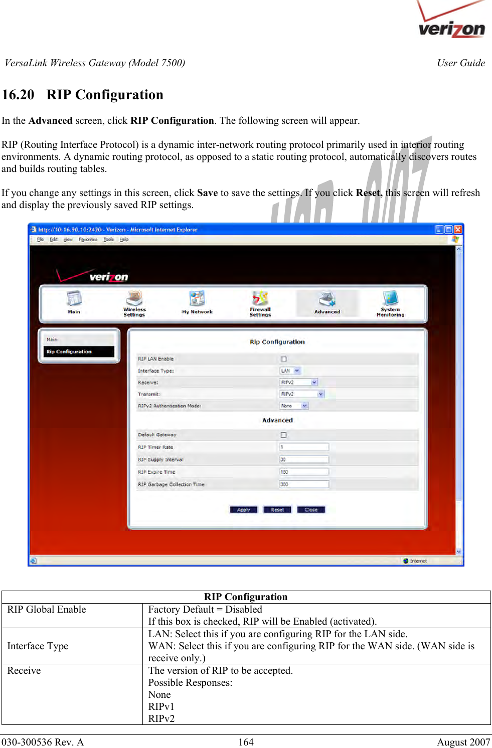
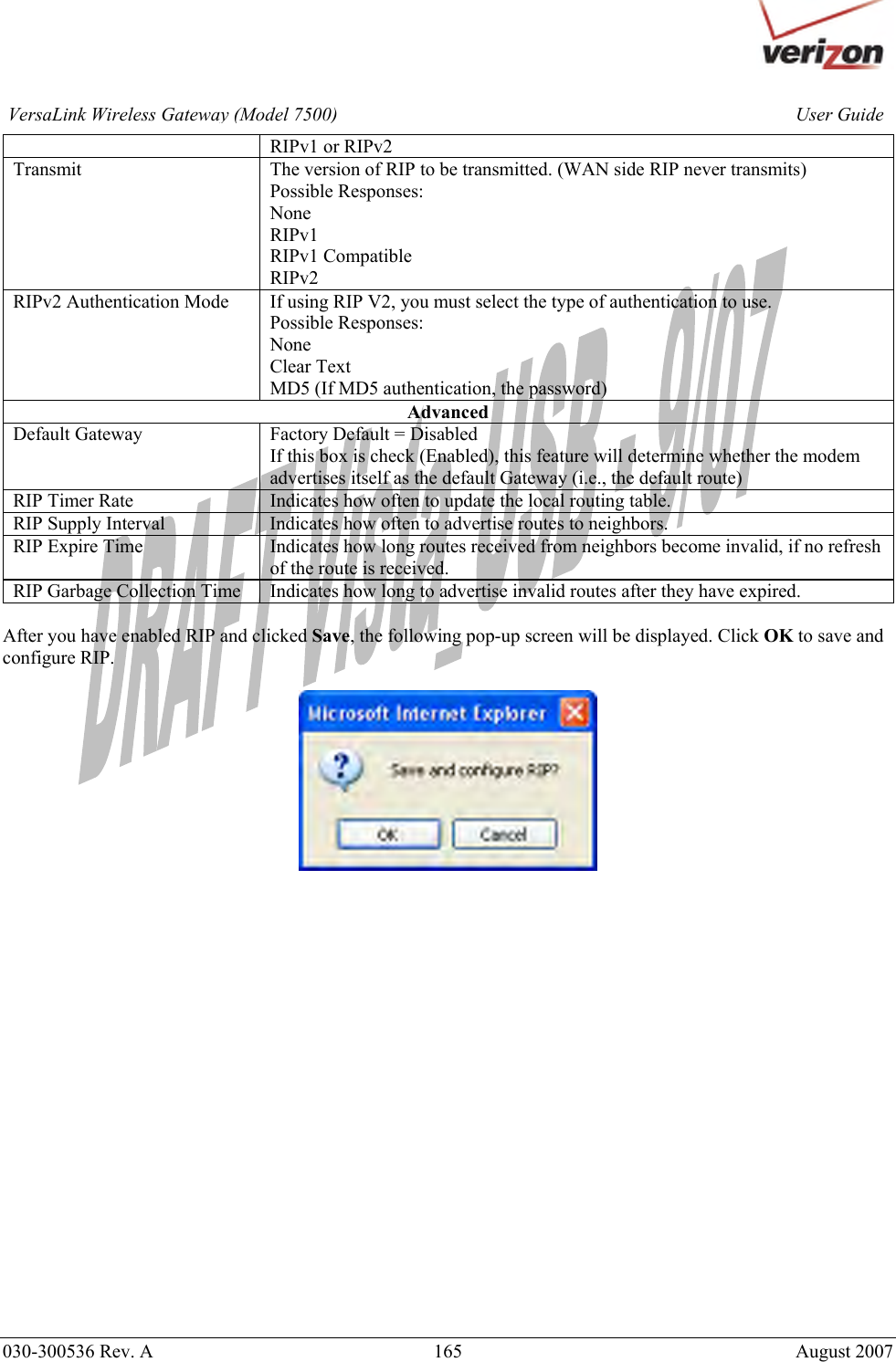
![030-300536 Rev. A 169 August 2007 User GuideVersaLink Wireless Gateway (Model 7500)17.2.1 System Logging In the Advanced Status screen, click System Logging. The following screen will be displayed. At the Logs drop-down menu, do any of the following: • Select All to list both Connection and System logs. • Select Connection to list all events related to connection activity (any traffic on the USB, Ethernet, or DSL ports). • Select System to list all events related to system activity (Time, Errors, Boot Information, etc.) • Select Diagnostic Tests to list all events related to the diagnostic logs • Select Wireless to list all events related to the voice event logs [Shouldn’t this screen display “wireless event logs”?]](https://usermanual.wiki/Westell/7500XX-07.User-Manual-Part-Three/User-Guide-882562-Page-44.png)
![030-300536 Rev. A 182 August 2007 User GuideVersaLink Wireless Gateway (Model 7500)UDP Unreal Tournament server 7777 (default gameplay port) 7778 (server query port) 7779,7779+ are allocated dynamically for each helper UdpLink objects, including UdpServerUplin objects. Try starting with 7779-7781 and add ports if needed. 27900 server query, if master server uplink is enabled. Home master servers use other ports like 27500. Port 8080 is for UT Server Admin. In the [UWeb.WebServer] section of the server.ini file, set the ListenPort to 8080 and ServerName to the IP assigned to the Gateway from Verizon. USENET News Service 143 TCP VNC, Virtual Network Computing 5500 TCP, 5800 TCP, 5900 TCP Westwood Online, C&C 4000 TCP/UDP, 1140-1234 TCP/UDP World Wide Web (HTTP) 80 TCP 443 TCP (SSL) 8008 or 8080 TCP (PROXY) Xbox Live 88 TCP/UDP, 3074 TCP/UDP Yahoo Messenger Chat 5000-5001 TCP Yahoo Messenger Phone 5055 UDP NAT/VPN Support IPSec Encryption IPSec using AH can not be supported through NAT. IPSec using ESP and L2TP can be supported via an ALG L2TP IPSec using ESP and L2TP can be supported via an ALG. PPTP Works through NAT.](https://usermanual.wiki/Westell/7500XX-07.User-Manual-Part-Three/User-Guide-882562-Page-57.png)