Contents
- 1. User Manual Part One
- 2. User Manual Part Three
- 3. User Manual Part Two a
- 4. User Manual Part Two b
User Manual Part Three
030-300536 Rev. A 126 August 2007
User GuideVersaLink Wireless Gatewa
y
(
Model 7500
)
15.6 Static NAT
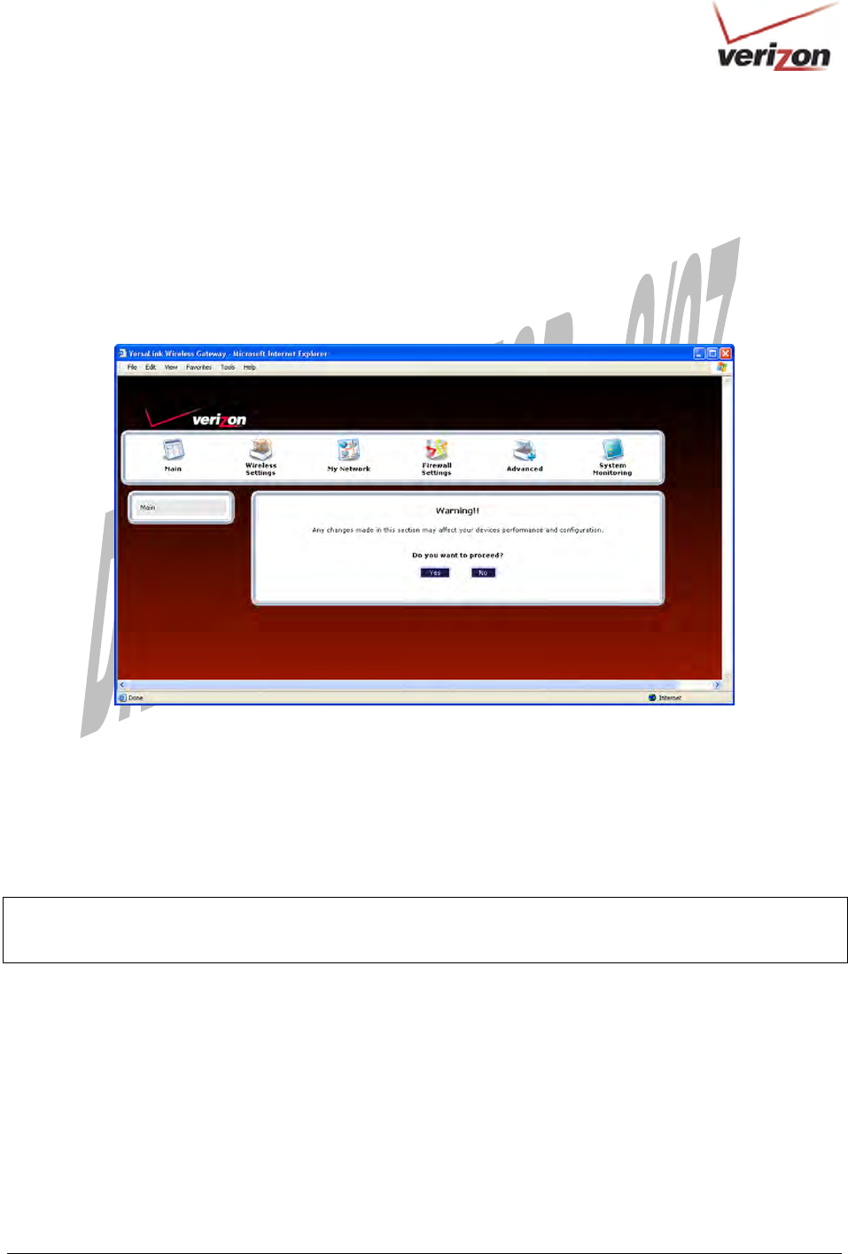
In the Firewall Settings screen, select Static NAT from the submenu options displayed at the left of the screen. A
warning screen will display the following message:
Any changes made in this section may affect your device’s performance and configuration.
Do you want to proceed?
Click Yes to proceed.
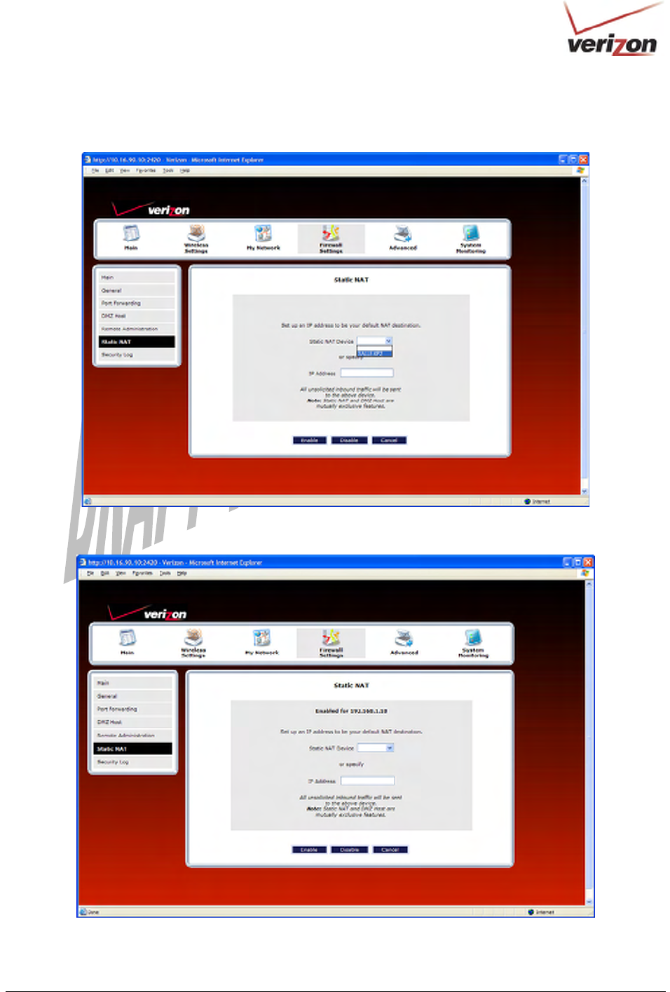
15.6.1 Enabling Static NAT
If you clicked Yes in the warning screen, the following Static NAT screen will appear. The Static NAT screen
allows you to configure your Router to work with the special NAT services. When the Router is configured for
Static NAT, any unsolicited packets arriving at the WAN will be forwarded to the selected device. This feature can
be used when you want to host a server for a specific application.
IMPORTANT:
Static NAT and DMZ Host are mutually exclusive features. Before you enable static NAT, confirm that DMZ Host
is disabled. If needed, refer to section 15.4.2 for details on disabling DMZ Host.
030-300536 Rev. A 127 August 2007
User GuideVersaLink Wireless Gatewa
y
(
Model 7500
)
To enable Static NAT, select a device from the Static NAT Device drop-down menu, or enter the IP address of the
device to which you want to assign Static NAT. Next, click Enable.
The following screen shows that Static NAT has been enabled for the device you selected.
030-300536 Rev. A 128 August 2007
User GuideVersaLink Wireless Gatewa
y
(
Model 7500
)
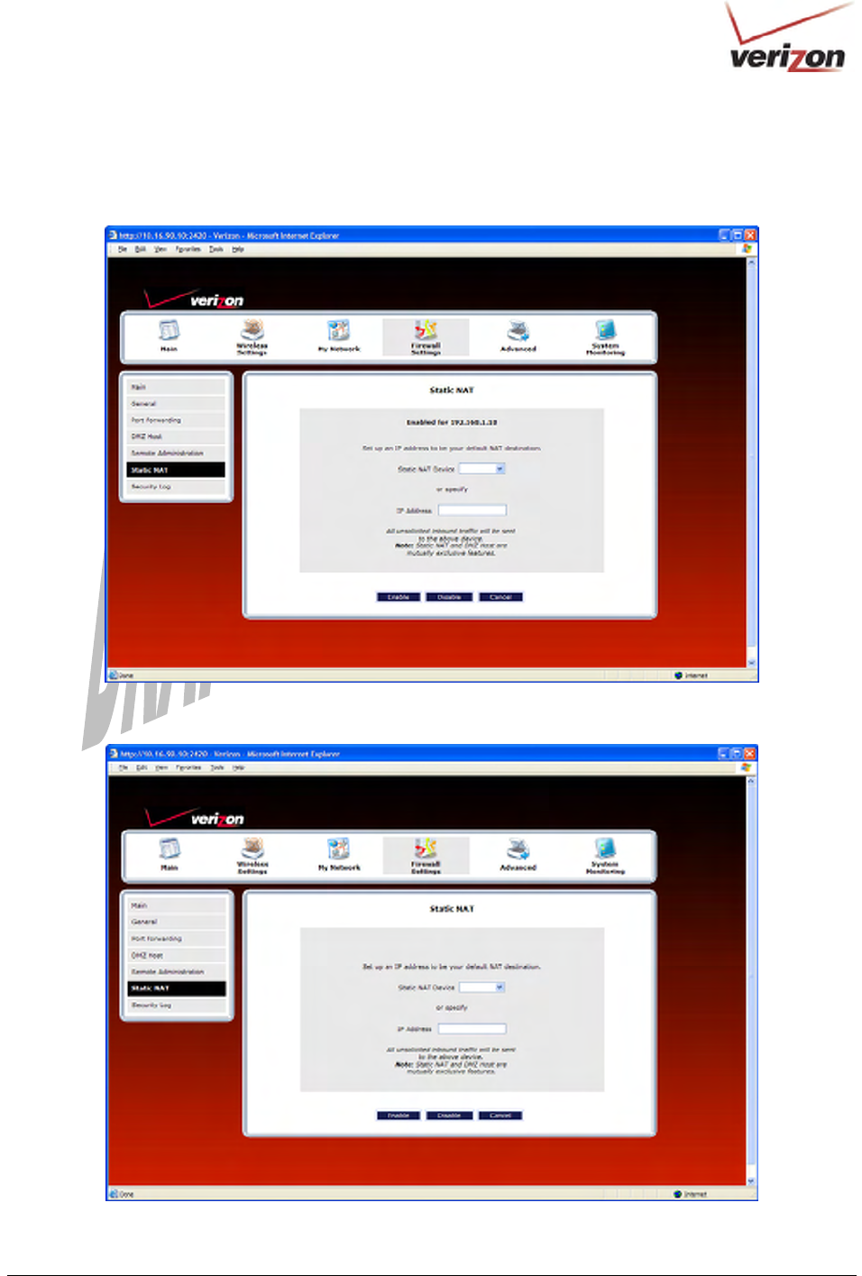
15.6.2 Disabling Static NAT
To disable Static NAT (if it has been previously enabled), click Disable in the Static NAT screen.
After you have disabled Static NAT the following screen will show no devices enabled for static NAT.

030-300536 Rev. A 129 August 2007
User GuideVersaLink Wireless Gatewa
y
(
Model 7500
)
15.7 Security Log
In the Firewall Settings screen, select Security Log from the submenu options displayed at the left of the screen. A
warning screen will display the following message:
Any changes made in this section may affect your device’s performance and configuration.
Do you want to proceed?
Click Yes to proceed.
If you clicked Yes in the warning screen, the following Security Log screen will appear. This screen alerts you of
noteworthy information sent to VersaLink from the Internet. The screen can contain 1000 entries, but a maximum of
50 entries are displayed at a time. Once 1000 entries have been logged, the oldest entry is removed to make space
for the new entries as they occur.
030-300536 Rev. A 130 August 2007
User GuideVersaLink Wireless Gatewa
y
(
Model 7500
)
Security Log
Close Clicking this button closes the security log screen.
Clear log Clicking this button removes all entries from the log.
Settings Clicking this button opens a new window that contains configuration settings for
selecting the information that you want logged.
Printable/savable format Clicking this button opens a new window that contains a list of all the logged
packets that can be saved or printed. You can send a copy of the Firewall log to a
designated printer.
Refresh Clicking this button updates the screen so that it displays the most current data.
Time Displays the time that the packet was sent.
Direction/Source Displays the direction of transmission.
Rule/Reason Displays the internal rule that caused the logged event. The internal rule is set up
under Firewall rules.
Alert Displays a description of the logged event.
Details Displays details about logged event.
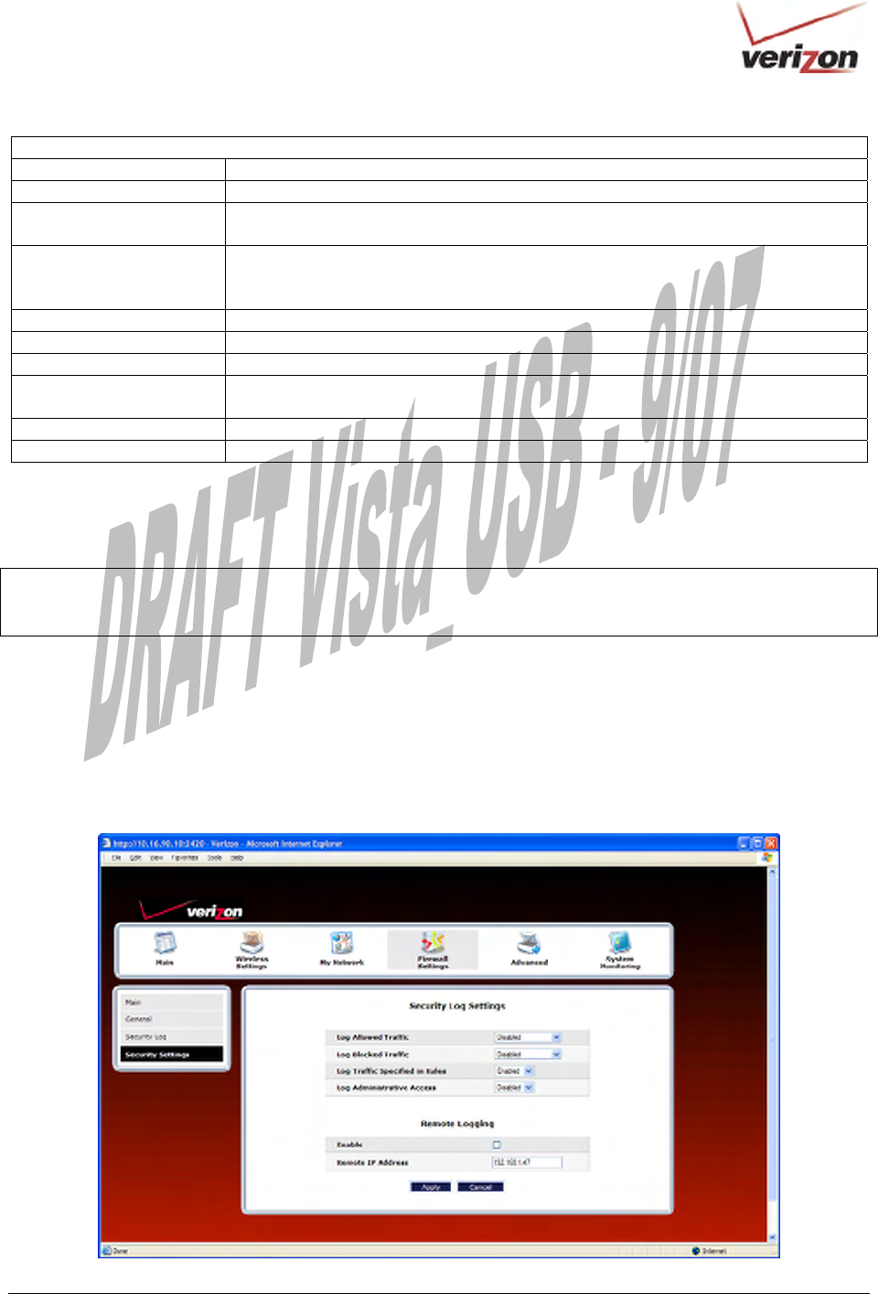
If you clicked Settings in the preceding Security Log screen, the following Firewall Log Settings screen will
appear. This screen allows you to configure firewall remote logging. Remote logging allows the firewall logs to be
sent to a machine running a syslog server.
NOTE: The syslog server must be configured to isten on udp port 514, which is usually the default port. In order for
the logs to be saved to the syslog server, the server should be configured to save the logs to a file. Some of the free
syslog servers available on the Internet are kiwisyslog, MT_syslog and 3Csyslog.
To configure Remote Logging, do the following:
1. Select the desired firewall log settings from the drop-down menus.
2. Click the Enable check box below Remote Logging (a check mark will appear in the box).
3. Type the IP address of the syslog server in the Remote IP Address field.
4. Click Apply to allow the settings to take effect.
030-300536 Rev. A 131 August 2007
User GuideVersaLink Wireless Gatewa
y
(
Model 7500
)
16. ADVANCED
The following sections discuss the advanced features of your Router, such as IP address distribution, firmware
upgrades, etc.
IMPORTANT: This section assumes that you have active DSL and Internet service.
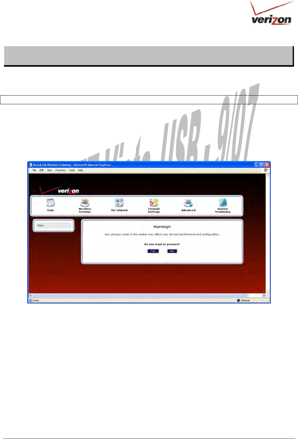
If you select Advanced in the top navigational menu, a warning screen will display the following message:
Any changes made in this section may affect your device’s performance and configuration.
Do you want to proceed?
Click Yes to proceed.
030-300536 Rev. A 132 August 2007
User GuideVersaLink Wireless Gatewa
y
(
Model 7500
)
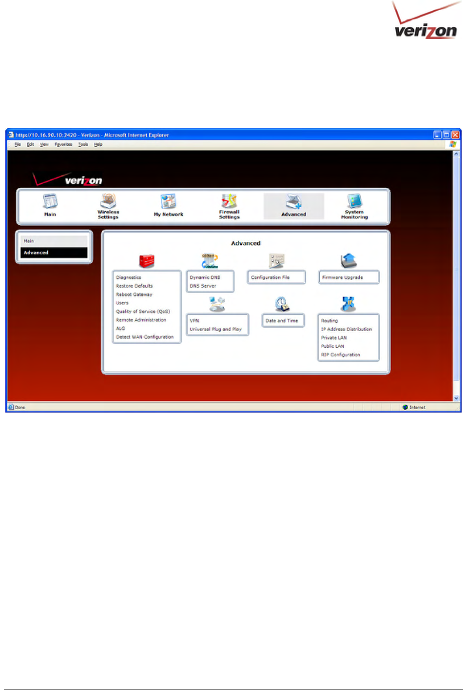
If you clicked Yes in the preceding warning screen, the following screen will appear. The Advanced screen allows
you to access various configurable features in your Router. To access a feature, click the link of the feature that you
want to access. The features shown in this page will be discussed in the following sections.
16.1 Diagnostics
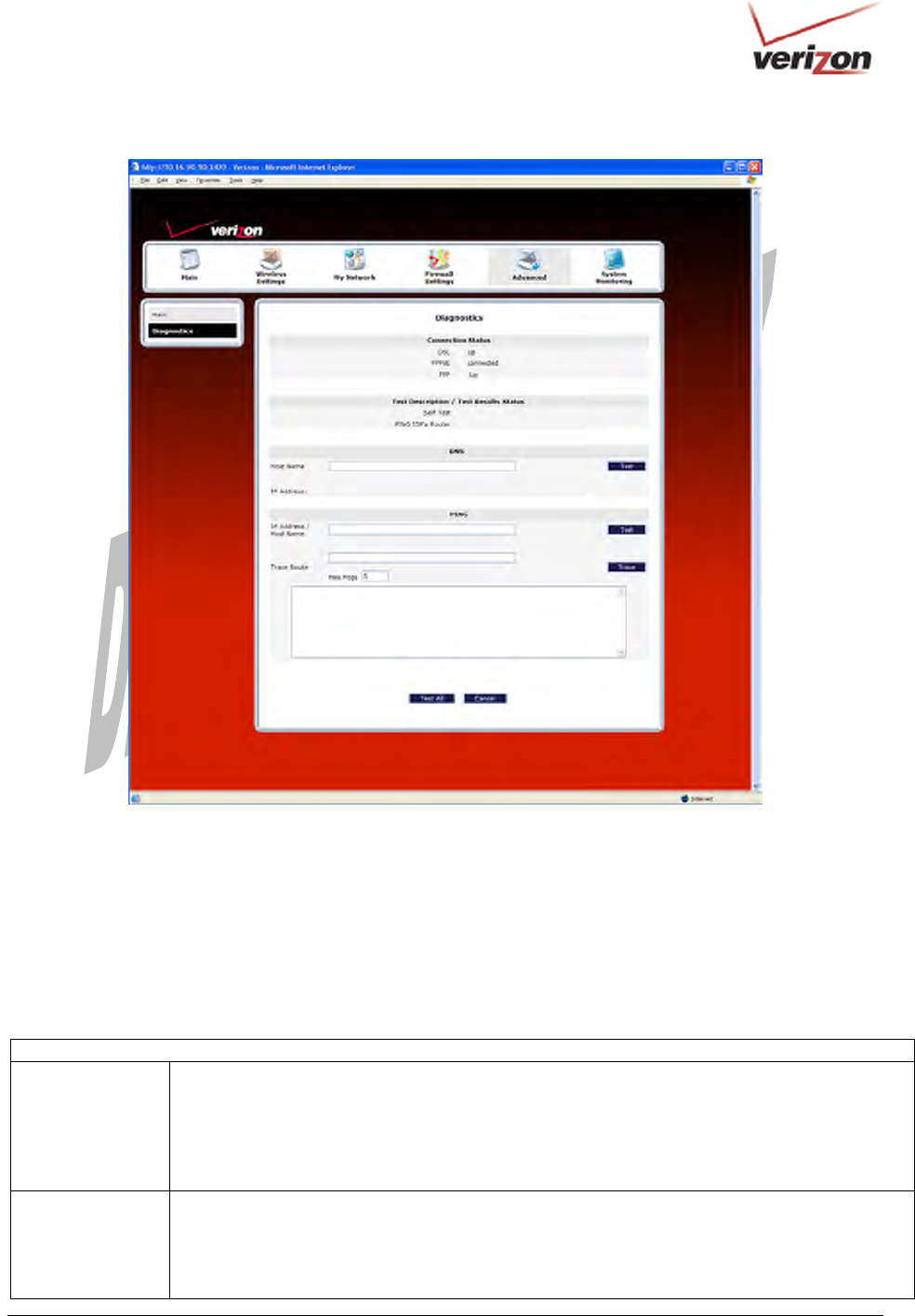
In the Advanced screen, click Diagnostics. The following screen will appear. Using this screen, you can run the
following diagnostics tests:
• To run a DNS test, type the appropriate host name in the field provided, and then click test.
• To run a PING test, type the appropriate IP address or host name in the field provided, and then click test.
• To run a Trace Route, type the appropriate IP address or host name in the field provided, and then click
trace.
• To run a full diagnostic test on your Router, click Test All.
030-300536 Rev. A 133 August 2007
User GuideVersaLink Wireless Gatewa
y
(
Model 7500
)
If you want to PING using the System Self Test screen (diagnostics page) shown above, enter your DNS or IP
address in the fields provided and click on the test button. The System Self Test will run a diagnostic test that
executes independent of firewall security settings. See the following table for test descriptions and possible
responses.
If you want to PING using the MS-DOS (shell) window, first you will need to check your firewall security setting.
(If you PING via DOS shell you are susceptible to firewall rules, as this PING is dependent on VersaLink's firewall
settings.) If your firewall is set to Medium or High, you will not be able to PING. You must set your firewall
security setting to Low or None.
Diagnostics
DSL VersaLink checks the status of the DSL connection.
Possible Responses:
Connection Up: VersaLink is operating correctly and has obtained synchronization with the
opposing network device.
Connection down: VersaLink is operating correctly, but has not synchronized with the opposing
device.
PPPoE Indicates that a PPPoE session is or is not established.
Possible Responses:
Session Up: A valid PPPoE session has been detected.
No Session: Currently there is no active PPPoE session established.
Initiating Session: A PPP session must be connected from the home page.

030-300536 Rev. A 134 August 2007
User GuideVersaLink Wireless Gatewa
y
(
Model 7500
)
PPP Indicates that a PPPoE or PPPoA session must already be established.
Possible Responses:
Connection Up: VersaLink has established a connection
No Connection: There is no PPP connection
Initiating Connection: The PPP connection process has been initiated
Connection Halted: A successful PPP connection was halted
Cannot Connect: A PPP connection could not be made because of a PPPoE session failure.
Authorization Failure: The user name or password is incorrect.
Link Control Protocol Failed: Reestablish the session (from the home page).
Test Description / Test Results
Self Test Performs an integrity check of certain internal components of VersaLink.
PING ISP’s
Router
Performs an IP network check (i.e., an IP Ping) of the service provider’s VersaLink. This test
verifies that VersaLink can exchange IP traffic with an entity on the other side of the DSL line.
Possible Responses:
Success: VersaLink has detected an IP Remote Router connection.
No Response: The IP Remote Router does not answer the IP Ping.
Could not test: The test could not be executed due to Router settings. Check your DSL link or
your PPP session. You must have both a DSL link and a PPP connection established to execute a
PING.
DNS Performs a test to try to resolve the name of a particular host. The host name is entered in the
input box.
Possible Responses:
Success: VersaLink has successfully obtained the resolved address. The IP address is shown
below the host name input box.
No Response: VersaLink has failed to obtain the resolved address.
Host not found: The DNS Server was unable to find an address for the given host name.
No data, enter host name: No host name is specified.
Could not test: The test could not be executed due to VersaLink settings. Check your DSL link
or your PPP session. You must have both a DSL link and a PPP connection established to
execute a PING.
IP Address IP Address of the Host Name.
PING
(via IP Address or
Host Name)
Performs an IP connectivity check to a remote computer either within or beyond the service
provider’s network. You can PING a remote computer via the IP address or the DNS address. If
your PING fails, try a different IP or DNS address.
Possible Responses:
Success: The Remote Host computer was detected.
No Response: There was no response to the Ping from the remote computer.
No name or address to PING: No host name or IP address was specified.
Could not test: The test could not be executed due to Router settings. Check your DSL link or
your PPP session. You must have both a DSL link and a PPP connection established to execute a
PING.
Trace Route
Determines the route taken to destination by sending Internet Control Message Protocol (ICMP)
echo packets with varying IP Time-To-Live (TTL) values to the destination. Trace Route is used
to determine where the packet is stopped on the network.
030-300536 Rev. A 135 August 2007
User GuideVersaLink Wireless Gatewa
y
(
Model 7500
)
16.2 Restore Defaults
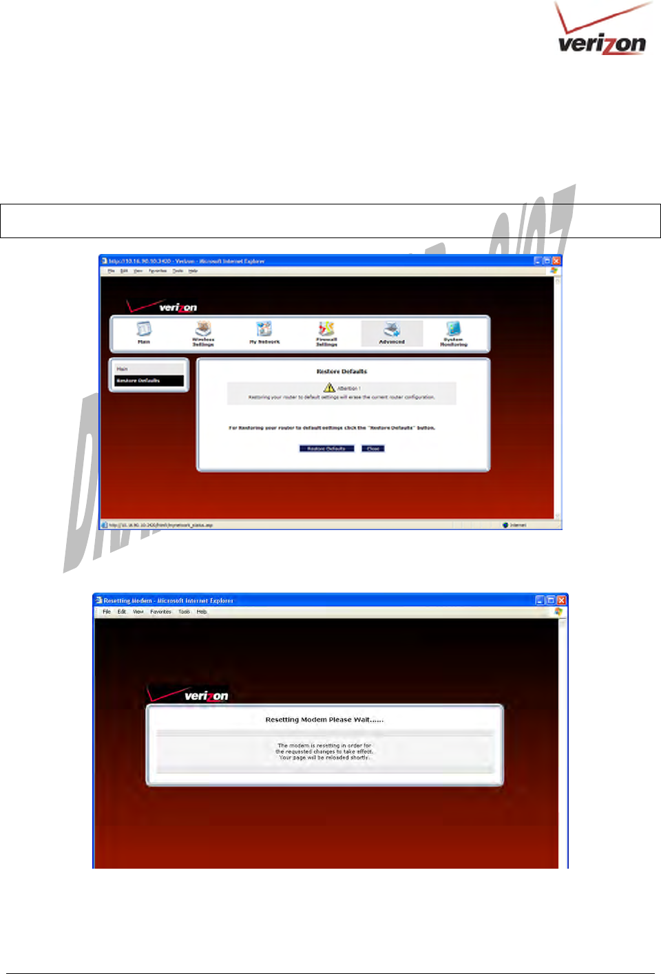
In the Advanced screen, click Restore Defaults. This screen allows you to restore the Router to its factory default
settings. To restore the Router, click the Restore Defaults button.
IMPORTANT: If you click Restore Defaults, any settings that you have configured in the Router will be erased,
and any data that the Router has reported will be lost.
If you clicked Restore Defaults, the following screen will appear. Please wait a brief moment while the Router
resets.
After the Router has reset, the Router Secure screen will be displayed. Follow the instructions explained in section
8.1, “Logging on to the Router,” to log on to your Router.
030-300536 Rev. A 136 August 2007
User GuideVersaLink Wireless Gatewa
y
(
Model 7500
)
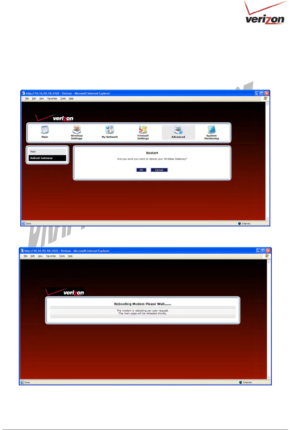
16.3 Reboot Gateway
In the Advanced screen, click Reboot Gateway. This screen allows you to reboot your Router without losing any
customized settings that you have made in the Router. Click OK to reboot your Router.
If you clicked OK, the following screen will appear. Please wait a brief moment while the Router reboots.
030-300536 Rev. A 137 August 2007
User GuideVersaLink Wireless Gatewa
y
(
Model 7500
)
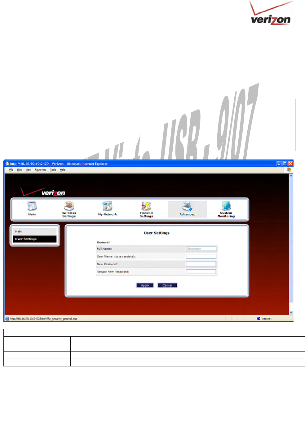
16.4 Users
In the Advanced screen, click Users. The following User Settings screen allows you to change the administrator’s
user name and password. Type the desired values in the fields provided, and then click Apply to allow the settings
to take effect. Refer to section 8.2, “Changing the Password,” for details on this feature.
NOTE:
1. If the Router is password protected and you are not an authorized user, you will not be able to change the values
in this screen. (The Router cannot be configured unless an authorized user is logged on.) Contact your network
administrator for further instructions.
2. The values typed in the password fields will be masked for security purposes.
3. This feature changes the Administrator’s password, not the PPP password.
User Settings
Full Name Displays the Administrator name. This field will be dimmed and unavailable for changes.
User Name Type the Administrators user name. (This field is case sensitive.)
New Password Type the administrator’s new password.
Retype New Password Confirm the administrator’s new password
030-300536 Rev. A 138 August 2007
User GuideVersaLink Wireless Gatewa
y
(
Model 7500
)
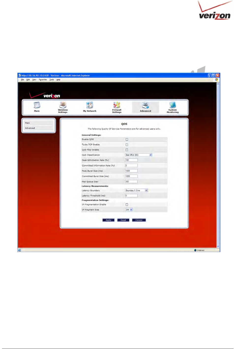
16.5 QOS
In the Advanced screen, click QOS. This screen allows you to configure Quality of Service parameters in the
Router. Select the desired Quality of Service settings, and then click Apply to allow the setting to take effect.
030-300536 Rev. A 139 August 2007
User GuideVersaLink Wireless Gatewa
y
(
Model 7500
)
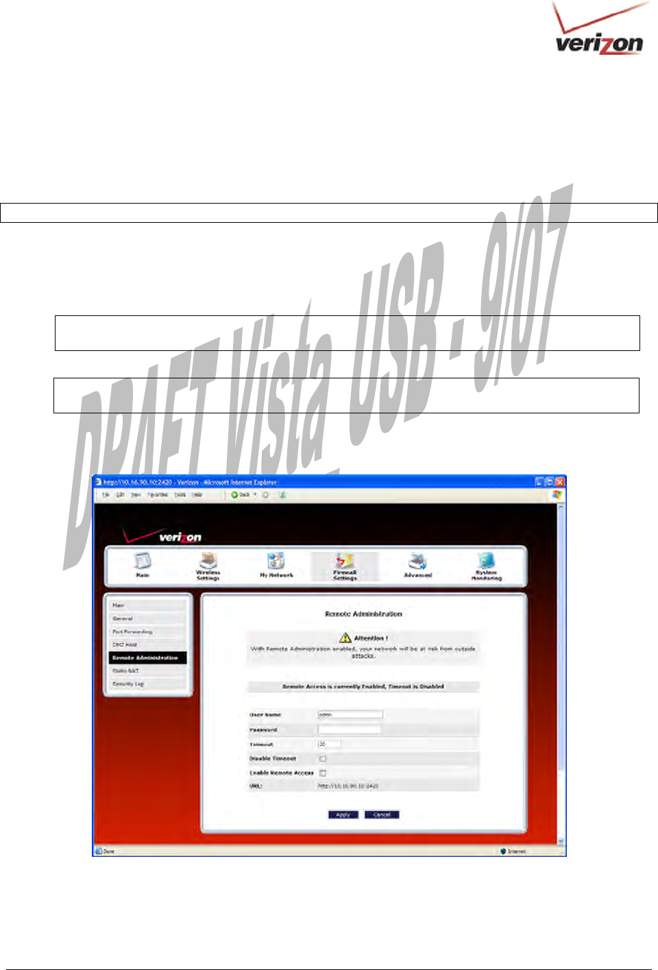
16.6 Remote Administration
In the Advanced screen, click Remote Administration. This screen allows you to configure your Router so that it
can be accessed remotely via a URL. Configure this feature to allow maintenance or troubleshooting for your Router.
WARNING: With Remote Administration enabled, your network will be at risk from outside attacks.
To enable Remote Administration, do the following:
1. Type the desired user name.
2. Type the desired password.
NOTE: The password should be at least 4 characters long and should not exceed 32 characters. Do not
type a blank space or asterisks in the Password field. The password is case sensitive.
3. Enter the number of minutes after which remote access will disconnect, if it is idle.
NOTE: If you click the Disable Timeout check box (a check mark will appear in the box), this will
override the preceding timeout minutes, and remote access will remain activated once you enable it.
4. Click the Enable Remote Access check box (a check mark will appear in the box).
5. Click Apply to allow the settings to take effect.
030-300536 Rev. A 140 August 2007
User GuideVersaLink Wireless Gatewa
y
(
Model 7500
)
Remote Administration
User Name Default = admin
The name used for the Remote Administration session. The only valid characters are (a-
z, A-Z, 0-9). The user name must be at least 6 characters and must not exceed 12
characters long.
Password The password used for the remote administration session. Do not use spaces or double-
quotes in the password field. The user name must be at least 6 characters and must not
exceed 12 characters long.
Timeout Default = 20 minutes
The interval (in minutes) after which the remote access will disconnect, if it is idle.
Disable Timeout Default = deactivated
To activate the Disable Timeout feature, click this box (a check mark will appear).
Clear the box to deactivate this feature.
Enable Remote Access Default = deactivated
Click this box (a check mark will appear) to activate Enable Remote Access.
Clear the box to deactivate this feature.
Remote URL Displays the URL for the remote access session.
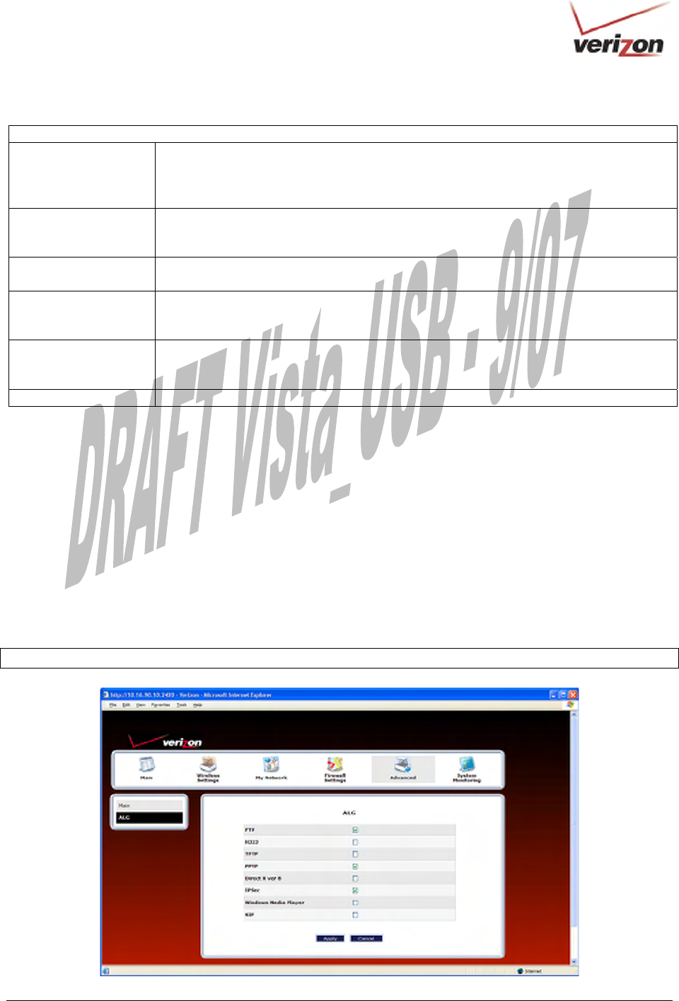
16.7 ALG
In the Advanced screen, click ALG. This screen allows you to configure your Router so that it can be accessed
remotely via a URL. Configure this feature to allow maintenance or troubleshooting for your Router. This page
enables you to configure application-level gateway (ALG) services for your Gateway. Click on the box of each
service that you want to enable (a check mark will appear in the box). After you have configured the desired
settings, click Save to save the settings.
Enabling an ALG service opens the IP ports associated with the corresponding service. For example, if you have an
IPSec client running on a LAN-side PC attached to the TriLink, it is necessary to enable the IPSec ALG. Enabling
IPSec opens the default ports used by IPSec, 500 and 1500 so that traffic to and from the IPSec client may pass through.
NOTE: When the firewall level is set to “High,” some services may not be configurable.
030-300536 Rev. A 141 August 2007
User GuideVersaLink Wireless Gatewa
y
(
Model 7500
)
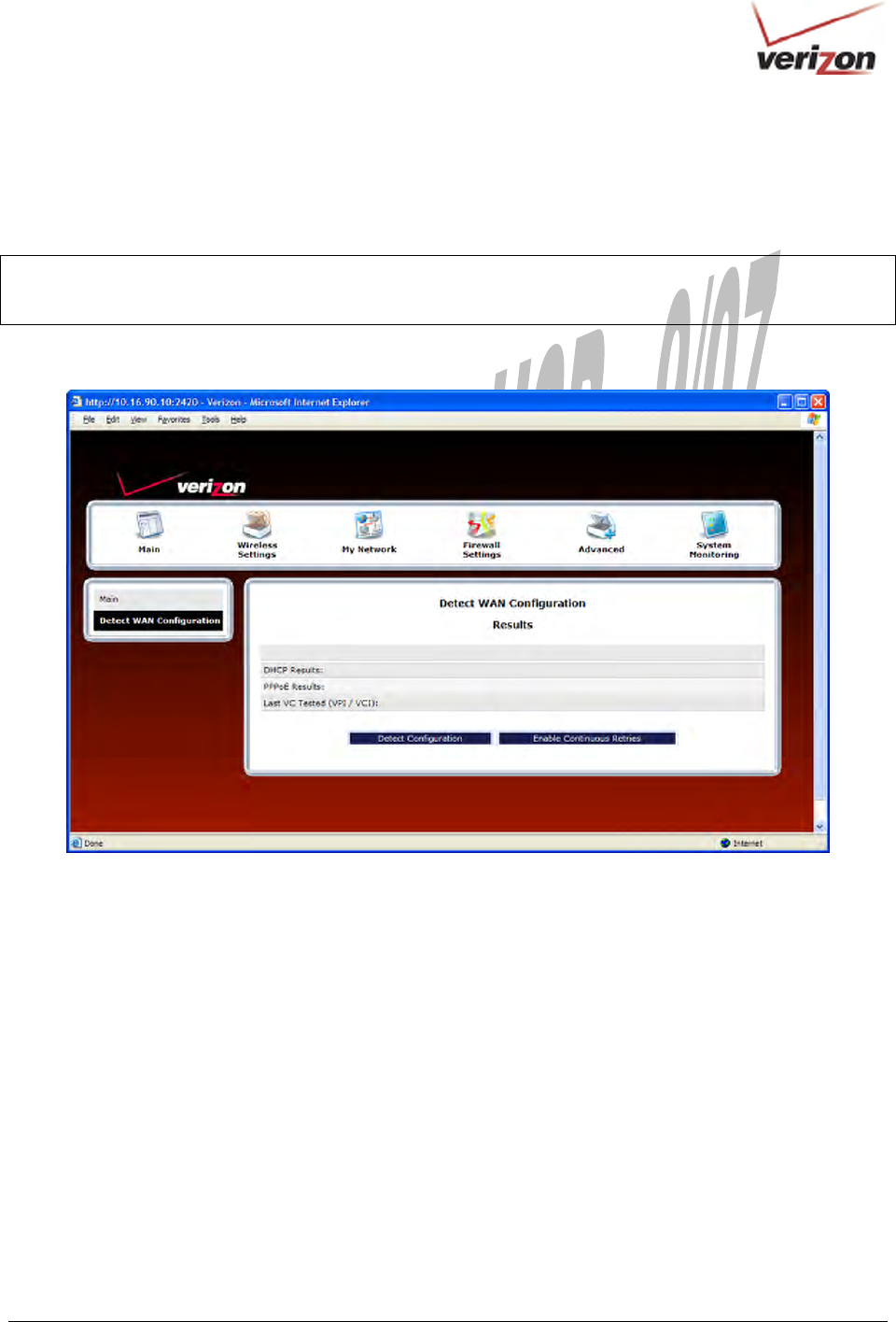
16.8 Detect WAN Configuration
In the Advanced screen, click Detect WAN Configuration. This screen displays the details of your WAN
connection.
NOTE: If you have not established and DSL connection with Verizon’s equipment and have not established an
Internet connection with Verizon, the Router will report Detection Disabled. Confirm that you have Internet
connection with Verizon. If problems persist, contact Verizon.
To check your WAN connection, click Detect Configuration. The Router will be reset.
030-300536 Rev. A 142 August 2007
User GuideVersaLink Wireless Gatewa
y
(
Model 7500
)
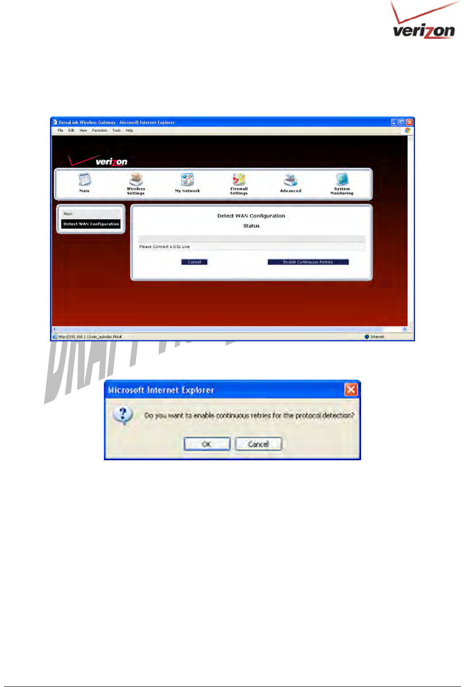
If no connection is detected, the following screen will appear. Click Enable Continuous Retries. The Router will
automatically continue to check the WAN connection. After a WAN connection is detected, the Router will report
the results.
If you clicked Enable Continuous Retries, the following pop-up screen will appear. Click OK to continue.
030-300536 Rev. A 143 August 2007
User GuideVersaLink Wireless Gatewa
y
(
Model 7500
)
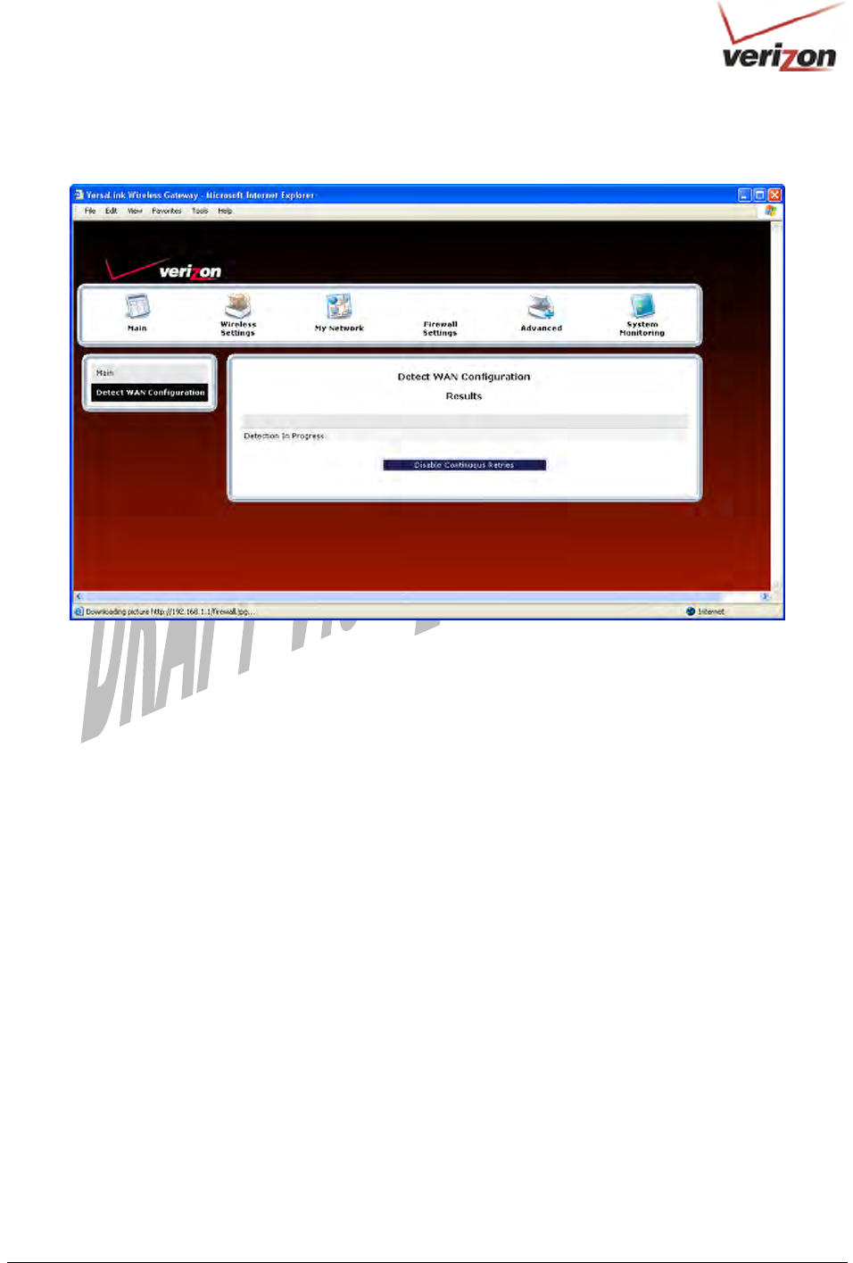
If you clicked OK, the following screen will appear. If want to disable continuous retries, click Disable Continuous
Retries.
030-300536 Rev. A 144 August 2007
User GuideVersaLink Wireless Gatewa
y
(
Model 7500
)
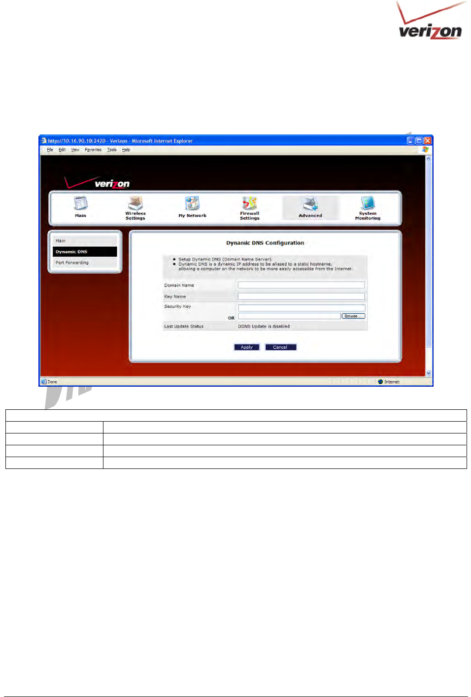
16.9 Dynamic DNS Configuration
In the Advanced screen, click Dynamic DNS Configuration. Dynamic DNS is a dynamic IP address that can
aliased to a static hostname, allowing a computer on the network to be more easily accessible from the Internet.
Dynamic DNS Configuration
Domain Name This is the domain name with which the dynamic DNS client is registered.
Key Name Provided by your service provider.
Security Key Provided by your service provider.
Last Update Status Provided by your service provider.
030-300536 Rev. A 145 August 2007
User GuideVersaLink Wireless Gatewa
y
(
Model 7500
)
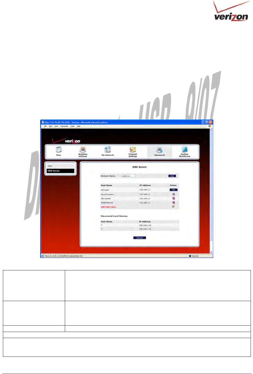
16.10 DNS Server
In the Advanced screen, click DNS Server. The following screen will appear. Your Router contains a built-in DNS
server. When an IP address is assigned, the Router will interrogate the new device for a machine name using several
well-known networking protocols. Any names learned will dynamically be added to the DNS server’s table of local
hosts.
Do any of the following:
• To rename the Domain Name, type a domain in the Domain Name field and then click Set.
• To add a host name, click Add DNS Entry
Domain Name
NOTE: Some ISP’s may
require the name for
identification purposes.
This field allows you to enter a Domain Name for your Router
To add a Domain Name, in the field under User Assigned DNS, type in your new
domain name and click Set.
Host Name This field allows you to enter a HOST name for Router.
To add a new Host name, in the field under Static Host Assignment, type in the Host
Name and the IP address and click Set.
IP Address Displays the IP address that is assigned to the Host Name.
Discover Local Devices
This field displays a list of the computers on the LAN that were assigned a DHCP Address. The DNS name and
IP address entry of each discovered device is displayed. (The values in this field will be displayed barring any
propagation delays. If ‘No Discovered Devices’ is displayed, manually refresh the screen.)
030-300536 Rev. A 146 August 2007
User GuideVersaLink Wireless Gatewa
y
(
Model 7500
)
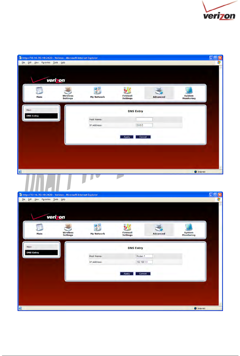
If you clicked ADD DNS Entry, the following screen will appear. Type the Host Name and IP Address in the
fields provided. Then, click Apply to continue.
For example, the following screen shows DNS values in the fields. Click Apply.
030-300536 Rev. A 147 August 2007
User GuideVersaLink Wireless Gatewa
y
(
Model 7500
)
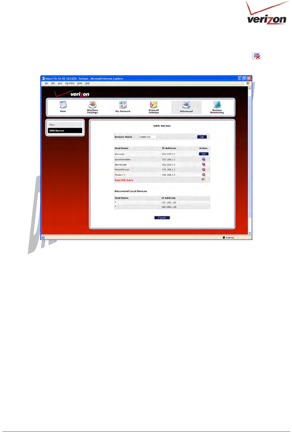
If you clicked Apply, the following screen will be displayed. This screen shows that the Host Name and IP
Address have been added to the DNS server. If you want to delete a DNS entry, click the delete icon next to the
Host Name and IP address that you want to delete.
030-300536 Rev. A 148 August 2007
User GuideVersaLink Wireless Gatewa
y
(
Model 7500
)
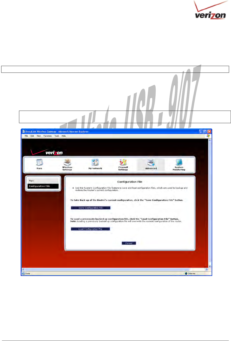
16.11 Configuration File
In the Advanced screen, click Configuration File. This screen allows you to save and load configuration files, which
are used to back up and restore the Router’s current configuration.
NOTE: Backup settings are stored in a separate area of flash, not to an external backup source.
Do one of the following:
• Click Save Configuration File to back up the Router’s current configuration.
• Click Load Configuration File to load a previously backed up configuration file.
IMPORTANT: Loading a previously backed up configuration file will overwrite the Router’s current
configuration, and any data the Router has reported will be lost.
030-300536 Rev. A 149 August 2007
User GuideVersaLink Wireless Gatewa
y
(
Model 7500
)
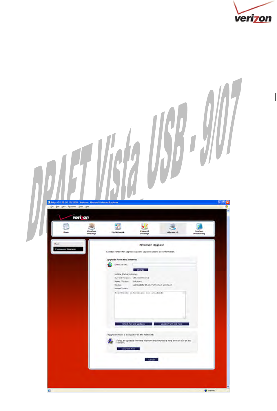
16.12 Firmware Upgrade
In the Advanced screen, click Firmware Upgrade. This screen is used to update the firmware that controls the
operation of your Router. The updated firmware may be loaded from a CD-ROM, from a file stored on a local hard
drive within your network, or from an update file stored on an Internet server.
IMPORTANT: The configurable settings of your Router may be erased during the upgrade process.
Do any of the following:
• Click change to edit the path of the firmware update file. The path will appear in the Check at URL field.
• Click check for web updates to retrieve the firmware update file and display any available update
information. You must be connected to the Internet to use this option. NOTE: If you click check for web
updates and the page returns “bug information not available,” this indicates that the firmware update file is
not available.
• Click update from web now to download the firmware update file and to automatically update the Router
firmware if an update is available and applicable. You must be connected to the Internet to use this option.
• Click upgrade now to retrieve the firmware update file from a local hard drive or CD-ROM on your
Network. Internet connection is not required for this option.
030-300536 Rev. A 150 August 2007
User GuideVersaLink Wireless Gatewa
y
(
Model 7500
)
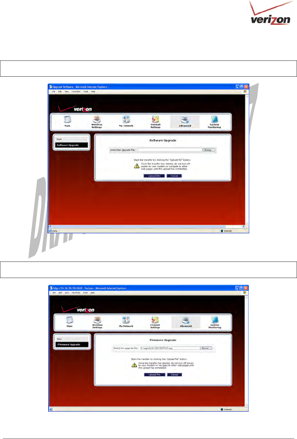
If you clicked Upgrade Now, the following screen will appear.
IMPORTANT: Once the transfer has started, do not turn off your Router’s power, and do not navigate to other
Web pages until the upload has completed.
Click Browse and then navigate to the location of the upgrade file; the path will appear in the window. Next, click
Upload file to begin the upload to your Router.
IMPORTANT: Once the transfer has started, do not turn off your Router’s power, and do not navigate to other
Web pages until the upload has completed.

030-300536 Rev. A 151 August 2007
User GuideVersaLink Wireless Gatewa
y
(
Model 7500
)
After the upload has completed, the following screen will appear. Please wait a brief moment while your Router is
being reset.
After the Router has been reset, the home page will appear. Confirm that you have a DSL link and that the PPP
Status displays UP. (If necessary, click Connect to establish your PPP session.)
030-300536 Rev. A 152 August 2007
User GuideVersaLink Wireless Gatewa
y
(
Model 7500
)
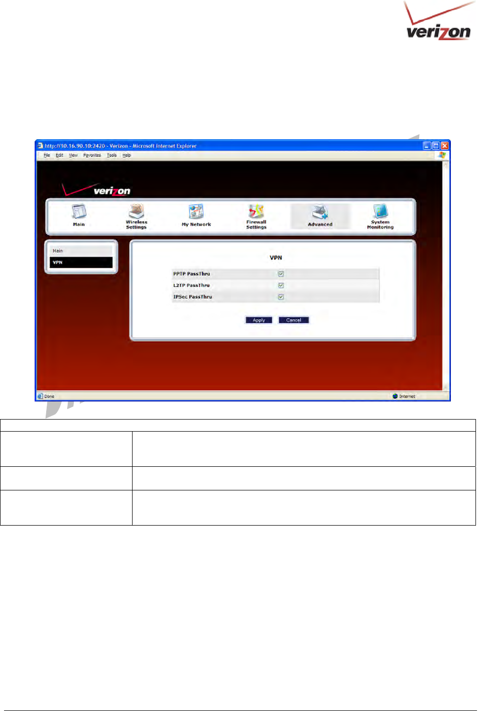
16.13 VPN
In the Advanced screen, click VPN. This feature allows you to select the VPN options for your Router.
VPN
PPTP Passthrough Factory Default = Enabled
If enabled (a check mark will appear in the box), PPTP will work through the
Gateway’s NAT function.
L2TP Passthrough Factory Default = Enabled
If enabled, IPSec using ESP and L2TP can be supported via an ALG.
IPSec Passthrough Factory Default = Enabled
If enabled, IPSec using ESP can be supported via an ALG. IPSec using AH cannot
be supported through NAT.
030-300536 Rev. A 153 August 2007
User GuideVersaLink Wireless Gatewa
y
(
Model 7500
)
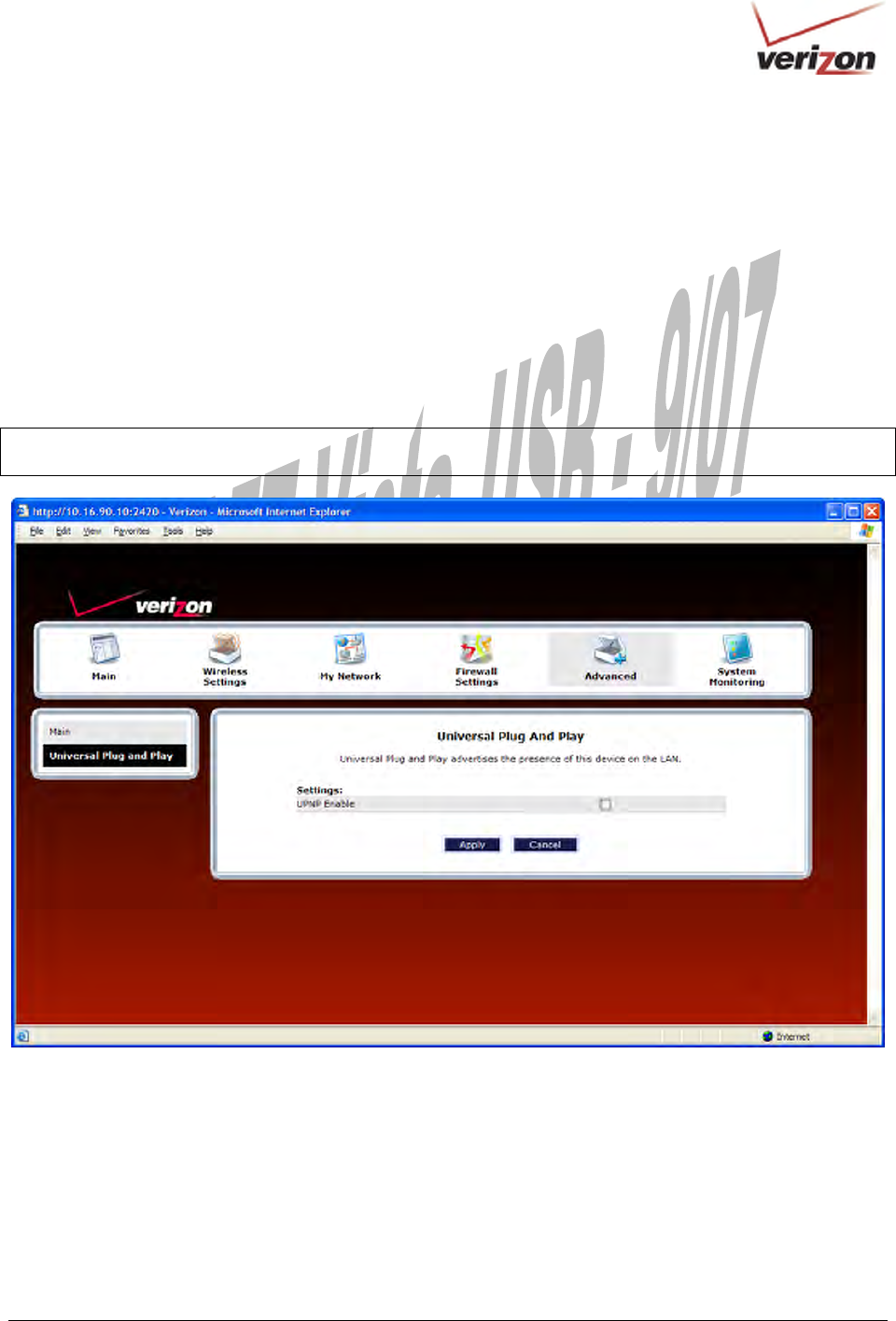
16.14 Universal Plug and Play
In the Advanced screen, click Universal Plug and Play. This feature advertises the presence of your Router on the
LAN.
To enable UPnP in your Router, do the following:
1. Click the UPNP Enable box (a check mark will appear in the box).
2. Click Apply to allow the change to take effect.
3. Click OK in the pop-up screen to reset the Router.
NOTE: By factory default UPnP is disabled. If you have previously enabled UPNP and now want to disable it, click
the UPnP Enable box to remove the check mark, and then click Apply.
030-300536 Rev. A 154 August 2007
User GuideVersaLink Wireless Gatewa
y
(
Model 7500
)
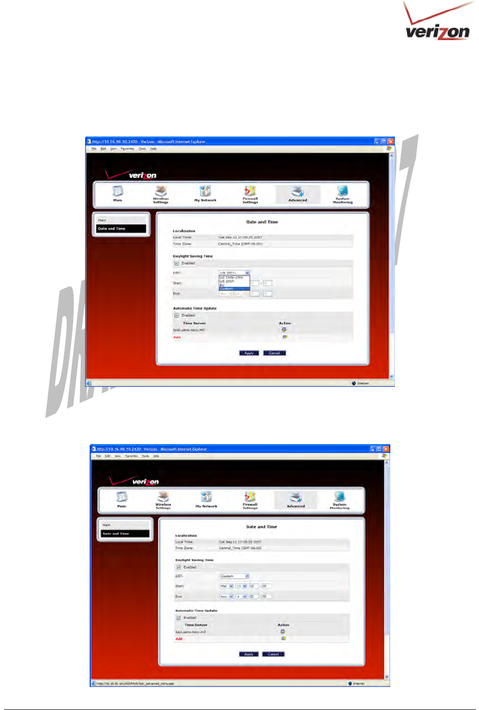
16.15 Time
In the Advanced screen, click Time. This feature allows you to set the date and time values on your Router. Enter the
desired settings, and then click Apply.
For example, if you selected Custom from the DST drop-down menu, the following screen will appear. Place a
check mark in the Daylight Saving Time check box, and then enter the desired Start and End values in the fields
provided. Click Apply to save the settings.
030-300536 Rev. A 155 August 2007
User GuideVersaLink Wireless Gatewa
y
(
Model 7500
)
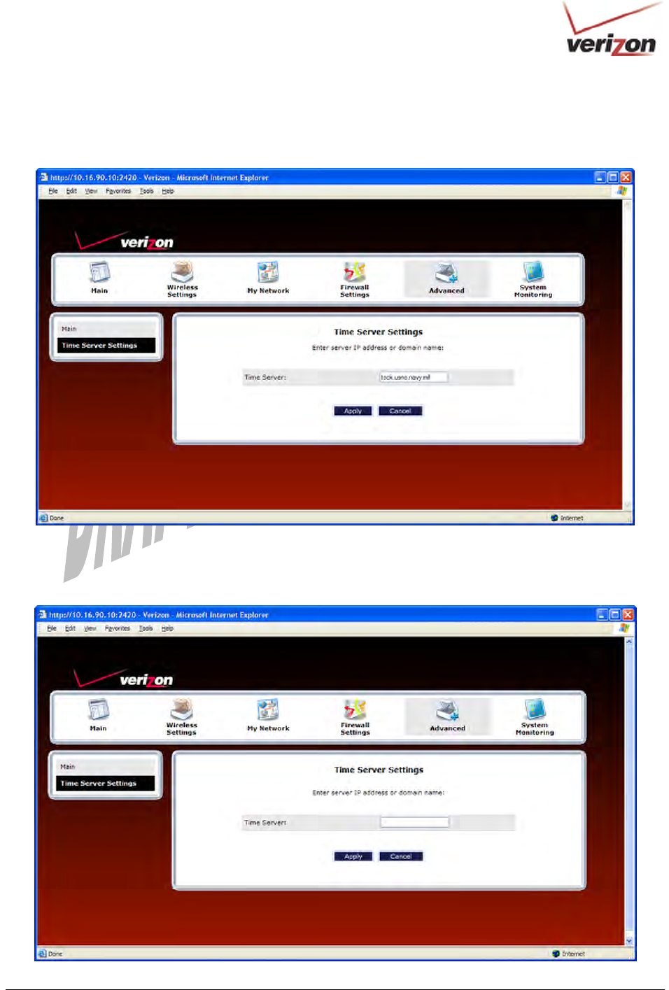
To edit the time server settings, in the Date and Time screen, click the adjacent edit icon. The following screen will
appear. Next, enter the IP address or domain name of the server you want to use. After you have entered the desired
value, click Apply to save the settings.
To add a time server entry, at the Date and Time screen, click Add. The following screen will appear. Next, enter
the IP address or domain name of the server you want to use. After you have entered the desired value, click Apply
to save the settings.
030-300536 Rev. A 156 August 2007
User GuideVersaLink Wireless Gatewa
y
(
Model 7500
)
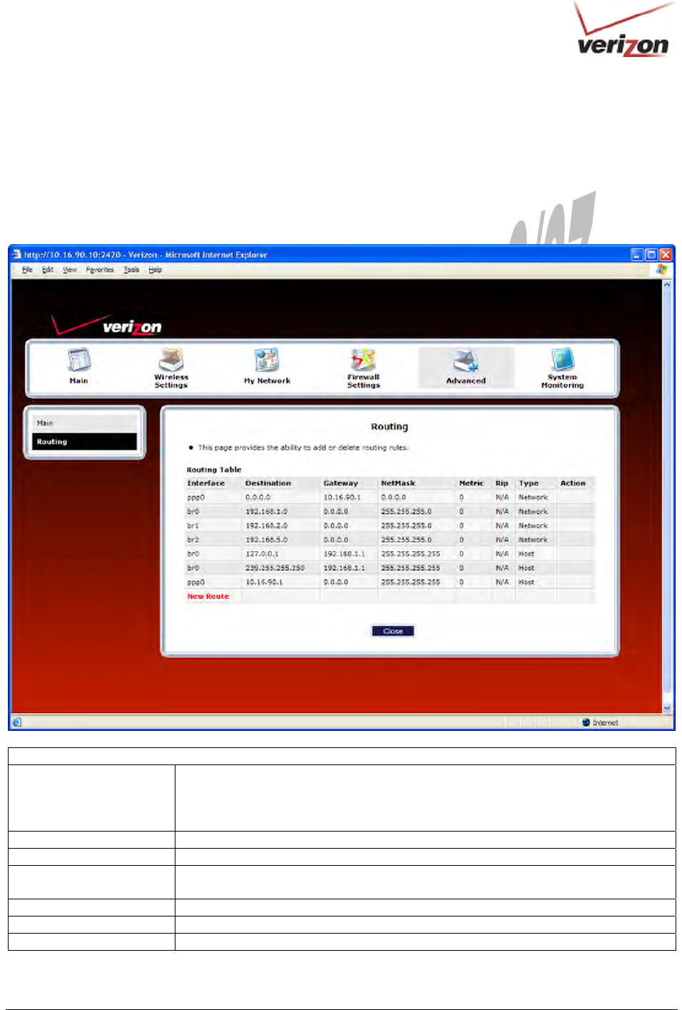
16.16 Routing
In the Advanced screen, click Routing. The Routing table maintains the routes or paths of where specific types of
data will be routed across a network.
To add a new static route in the Router, click New Route.
Routing
IP Interfaces The list of active interfaces on the Router and their IP and Subnet mask address.
eth0 is the local LAN interface.
lo0 is the loopback interface.
mainPPP is the WAN interface
Destination The IP address or subnet of the Route.
Gateway Indicates were to send the packet if it matches this route.
Netmask If the Route is a Network route, Subnet Mask is used to specify the subnet address.
If the Route is a Host route, then the Host Route check box should be selected.
Metric The RIP metric to be assigned to this route if and when it is advertised using RIP.
RIP Indicates whether a static route should be advertised via RIP.
Type Indicates the type of route: Network route or Host route.
030-300536 Rev. A 157 August 2007
User GuideVersaLink Wireless Gatewa
y
(
Model 7500
)
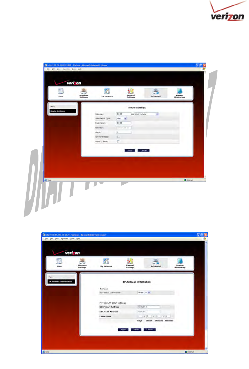
If you clicked New Route, the following screen will appear. Enter the appropriate values in the fields, and then click
Apply.
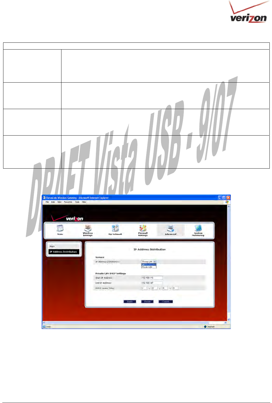
16.17 IP Address Distribution
In the Advanced screen, click IP Address Distribution. The following screen will appear. IP Address Distribution
allows you to configure the Router’s DHCP server to automatically assign IP address to local devices connected to
your LAN.
030-300536 Rev. A 158 August 2007
User GuideVersaLink Wireless Gatewa
y
(
Model 7500
)
IP Address Distribution
IP Address
Distribution
Factory Default = Private LAN
This setting allows VersaLink to automatically assign IP addresses to local devices
connected to the LAN.
Off = DHCP Server is disabled
Private LAN = DHCP addresses will be issued from the Private LAN DHCP server.
Start IP Address Factory Default = 192.168.1.15
This field displays the first IP address that the DHCP server will provide. The DHCP
Start Address must be within the IP address and lower than the DHCP End Address.
You can use any number from 0 to 254 in this address.
End IP Address Factory Default = 192.168.1.47
This field displays the last IP address that the DHCP server will provide. The DHCP
End Address must be within the IP address and higher than the DHCP Start Address.
You can use any number from 0 to 254 in this address.
DHCP Lease Time Factory Default = 01:00:00:00
Displays the amount of time the provided addresses will be valid, after which the DHCP
client will usually resubmit a request.
Note: This value must be greater than 10 seconds. Seconds must be between 0 and 59,
minutes must be between 0 and 59, and hours must be between 0 and 23.
By default Private LAN is already enabled. To disable the Private LAN DHCP server, select Off from the IP
Address Distribution drop-down menu.
030-300536 Rev. A 159 August 2007
User GuideVersaLink Wireless Gatewa
y
(
Model 7500
)
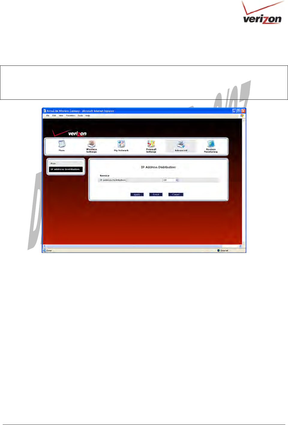
If you selected Off, the following screen will appear. Click Apply to save the settings. If you click Reset, the screen
will refresh, and the previously saved settings will remain active.
IMPORTANT:
1. Whenever you change the settings in a screen, the screen will display the changes; however, you must click
Apply to allow the changes to take effect in the Router. (Private LAN is the default for DHCP Server.)
2. After you disable the Private LAN DHCP server, reboot your computer to allow the changes to take effect.
030-300536 Rev. A 160 August 2007
User GuideVersaLink Wireless Gatewa
y
(
Model 7500
)
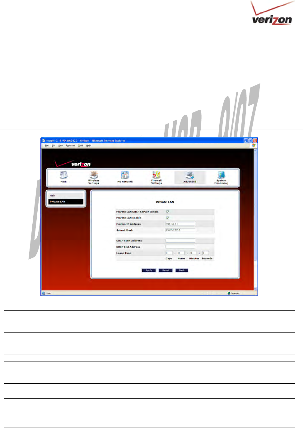
16.18 Private LAN—Configuring NAT
In the Advanced screen, click Private LAN. The following screen will appear. Private LAN allows you to set up a
network behind your Router.
If you change the settings in this screen, click Apply. If you click Reset, the screen will refresh and the previously
saved settings will remain active.
IMPORTANT: Whenever you change the settings in a screen, the screen will display the changes; however, you must
click Apply to allow the changes to take effect in the Router. (Private LAN is the default setting for VersaLink.)
Private LAN
Private LAN DHCP Server Enable Default = Enabled
If this box contains a check mark, this enables DHCP addresses to be
served from the Private LAN pool.
Private LAN Enable Default = Enabled
If this box contains a check mark, this enables the addresses from the
Private LAN to use the NAT interface.
Modem IP Address Displays the Router’s IP address.
Subnet Mask Displays the Subnet Mask, which determines what portion of an IP
address is controlled by the network and which portion is controlled by the
host.
DHCP Start Address Displays the first IP address that the DHCP server will provide.
DHCP End Address Displays the last IP address that the DHCP server will provide.
DHCP Lease Time Displays the amount of time the provided addresses will be valid, after
which the DHCP client will usually resubmit a request.
Note: The DHCP Lease Time value must be greater than 10 seconds. The default = 01:00:00:00. Seconds must be
between 0 and 59, minutes must be between 0 and 59, and hours must be between 0 and 23.
030-300536 Rev. A 161 August 2007
User GuideVersaLink Wireless Gatewa
y
(
Model 7500
)
If the settings you have entered in the Private LAN Configuration screen are incorrect, the following warning
messages may be displayed in pop-up screens. If this occurs, check the settings in the Private LAN Configuration
screen.
Warning Message Check Private LAN DHCP Settings
Start Address is not part of the Subnet Check the value in the DHCP Start Address field
End Address is not part of the Subnet Check the value in the DHCP End Address field
End Address is below the Start Address Check the value in the DHCP End Address field
Lease time must be greater than 10 seconds Check the values in the DHCP Lease Time fields
Seconds must be between 0 and 59 Check the Seconds value in the DHCP Lease Time field
Minutes must be between 0 and 59 Check the Minutes value in the DHCP Lease Time field
Hours must be between 0 and 23 Check the Hours value in the DHCP Lease Time field
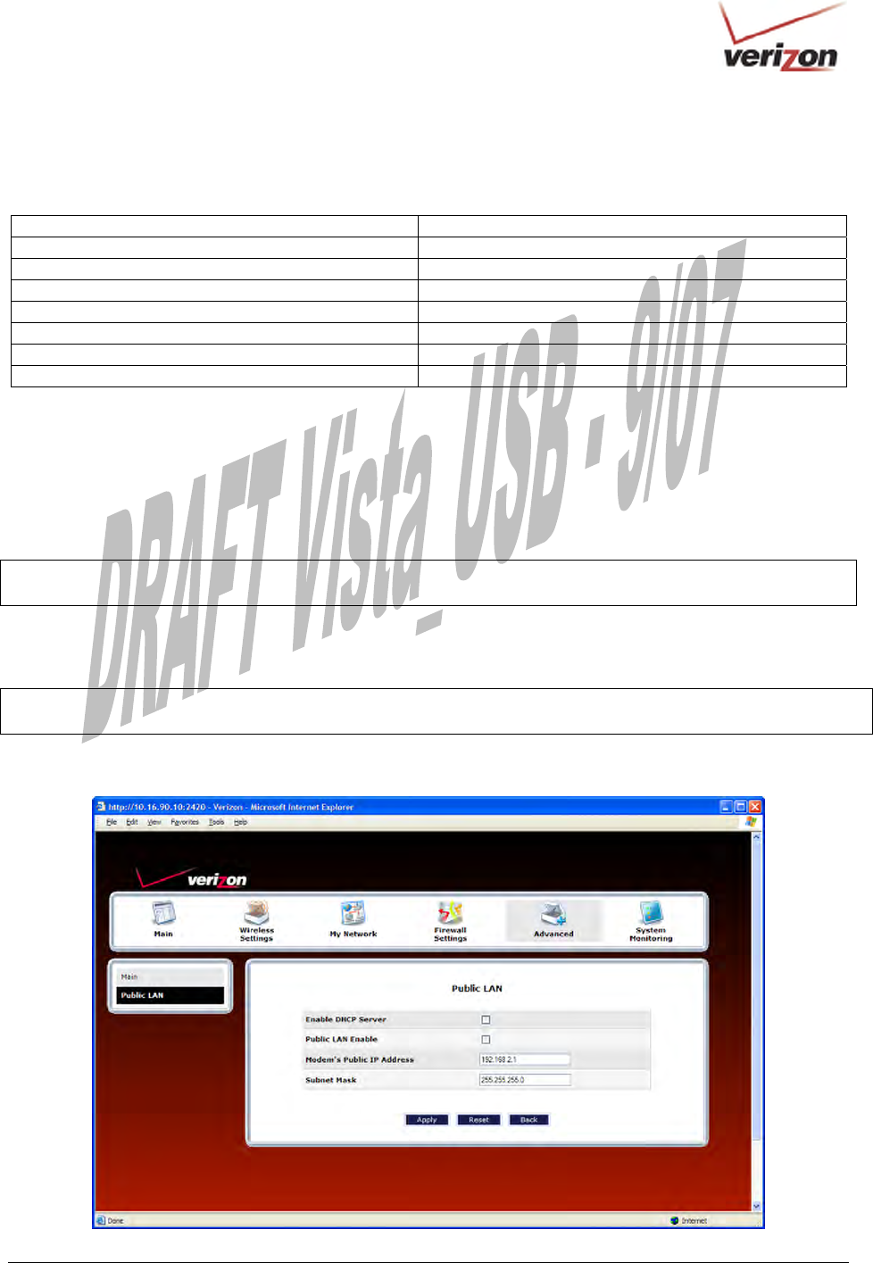
16.19 Public LAN—Multiple IP Address Passthrough
In the Advanced screen, click Private LAN. The following screen will appear. The Public LAN feature allows
VersaLink to use LAN IP addresses that are accessible from the WAN. Public LAN allows your computer to have
global address ability.
NOTE: To utilize the Public LAN feature in your VersaLink, Verizon must support Public LAN and Static IP. If
you have questions about the feature, contact Verizon for details.
If you change the settings in this screen, click Apply. If you click Reset, the screen will refresh and the previously
saved settings will remain active.
IMPORTANT: Whenever you change the Private LAN settings, the screen will display the changes; however, you
must click Apply to allow the changes to take effect in the Router. (Private LAN is the default setting for VersaLink.)
To enable Public LAN, click the Public LAN DHCP Server Enable box (a check mark will appear in the box).
030-300536 Rev. A 162 August 2007
User GuideVersaLink Wireless Gatewa
y
(
Model 7500
)
Public LAN
Public LAN DHCP Server Enable Default = Disabled (deselected)
If this box contains a check mark, this enables DHCP addresses to be
served from the Public LAN pool.
Public LAN Enable Default = Disabled (deselected)
If this box contains a check mark, this enables the addresses from the
Public LAN to bypass the NAT interface.
Public LAN IP Address Provides a Public IP Address if the service provider does not
automatically provide one.
Public LAN Subnet Mask Provides a Public Subnet Mask if the service provider does not
automatically provide one.
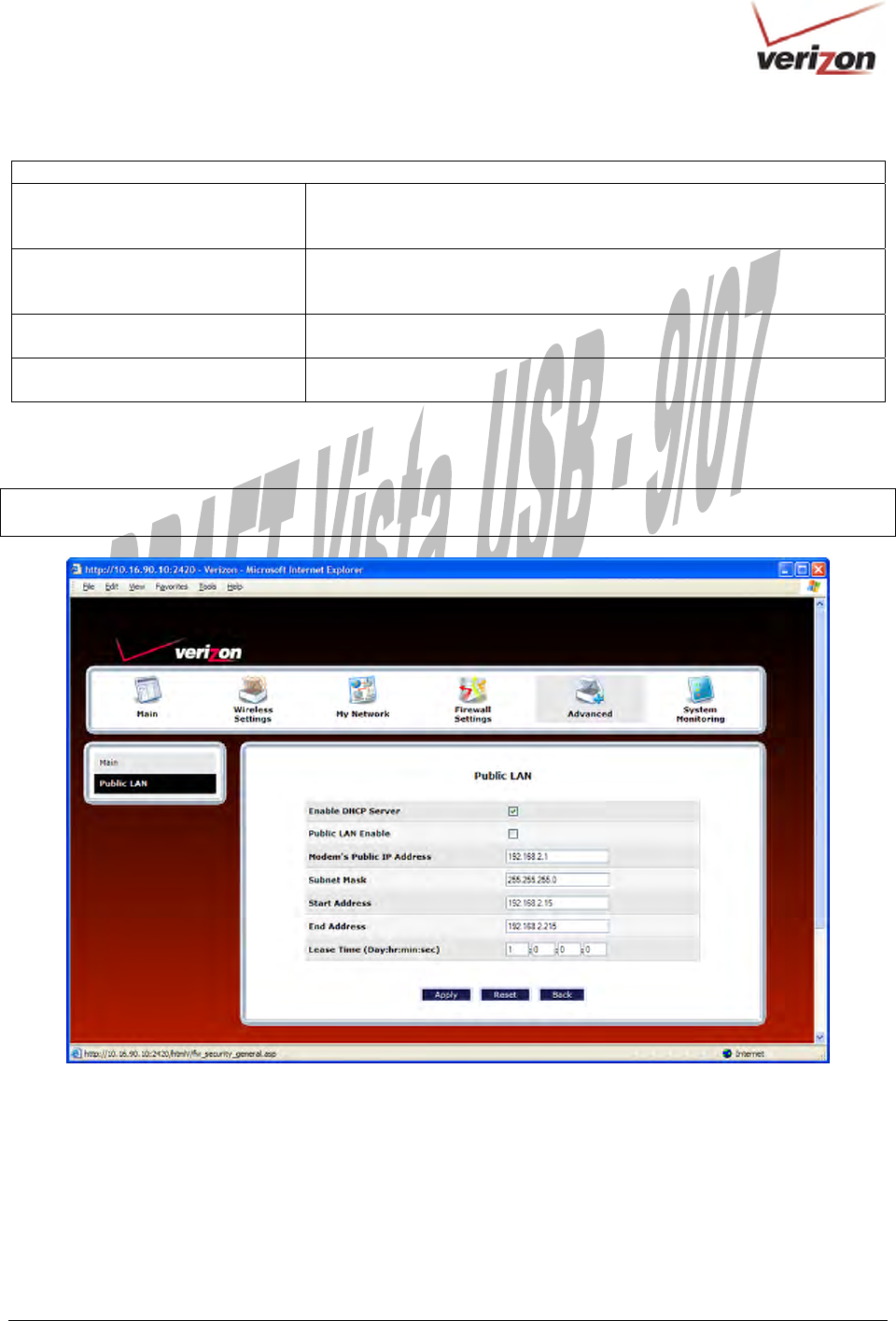
If you clicked the Public LAN DHCP Server Enable box, the following screen will appear. Click the Public LAN
Enable box (a check mark will appear in the box).
WARNING: By enabling the Public LAN DHCP Server, you automatically disable the Router’s Private LAN
DHCP Server. (Private LAN DHCP is the default setting for VersaLink.)
030-300536 Rev. A 163 August 2007
User GuideVersaLink Wireless Gatewa
y
(
Model 7500
)
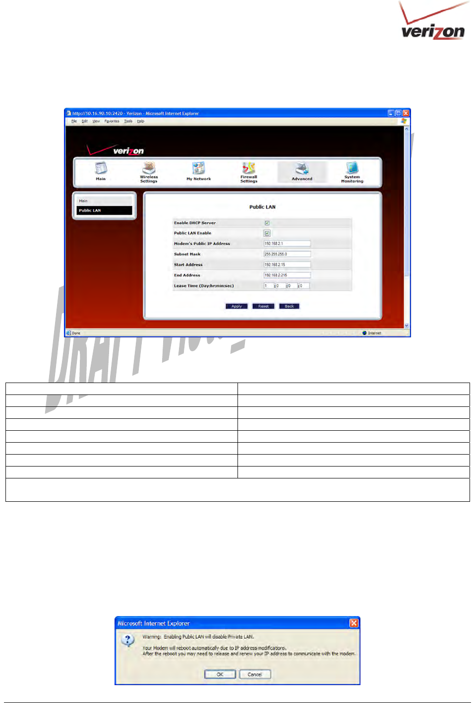
If you clicked the Public LAN Enable box, the following screen will appear. After you have made changes to this
screen, click Apply to allow the settings to take effect.
If the settings you have entered in the Public LAN Configuration screen are incorrect, the following warning
messages may be appear in pop-up screens. If this occurs, check the Public LAN Configuration settings.
Warning Message Check Public LAN DHCP Settings
Start Address is not part of the Subnet Check the value in the DHCP Start Address field
End Address is not part of the Subnet Check the value in the DHCP End Address field
End Address is below the Start Address Check the value in the DHCP End Address field
Lease time must be greater than 10 seconds Check the values in the DHCP Lease Time fields
Seconds must be between 0 and 59 Check the Seconds field at DHCP Lease Time
Minutes must be between 0 and 59 Check the Minutes field at DHCP Lease Time
Hours must be between 0 and 23 Check the Hours field at DHCP Lease Time
Note: The DHCP Lease Time value must be greater than 10 seconds. The default = 01:00:00:00. Seconds must be
between 0 and 59, minutes must be between 0 and 59, and hours must be between 0 and 23.
If you clicked Apply in the Public LAN screen, a warning screen will display the following message:
Warning: Enabling Public LAN will disable Private LAN.
Your Modem will reboot automatically due to IP address modifications.
After the reboot, you may need to release and renew your IP address to communicate with the modem.
Click OK to allow the modem to reboot. After the modem has rebooted, confirm that you have a DSL link and that
your PPP Status displays UP.
030-300536 Rev. A 164 August 2007
User GuideVersaLink Wireless Gatewa
y
(
Model 7500
)
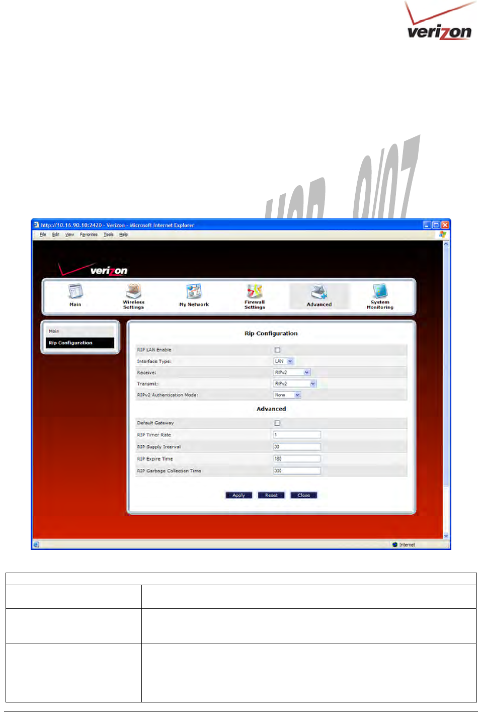
16.20 RIP Configuration
In the Advanced screen, click RIP Configuration. The following screen will appear.
RIP (Routing Interface Protocol) is a dynamic inter-network routing protocol primarily used in interior routing
environments. A dynamic routing protocol, as opposed to a static routing protocol, automatically discovers routes
and builds routing tables.
If you change any settings in this screen, click Save to save the settings. If you click Reset, this screen will refresh
and display the previously saved RIP settings.
RIP Configuration
RIP Global Enable Factory Default = Disabled
If this box is checked, RIP will be Enabled (activated).
Interface Type
LAN: Select this if you are configuring RIP for the LAN side.
WAN: Select this if you are configuring RIP for the WAN side. (WAN side is
receive only.)
Receive The version of RIP to be accepted.
Possible Responses:
None
RIPv1
RIPv2
030-300536 Rev. A 165 August 2007
User GuideVersaLink Wireless Gatewa
y
(
Model 7500
)
RIPv1 or RIPv2
Transmit The version of RIP to be transmitted. (WAN side RIP never transmits)
Possible Responses:
None
RIPv1
RIPv1 Compatible
RIPv2
RIPv2 Authentication Mode If using RIP V2, you must select the type of authentication to use.
Possible Responses:
None
Clear Text
MD5 (If MD5 authentication, the password)
Advanced
Default Gateway Factory Default = Disabled
If this box is check (Enabled), this feature will determine whether the modem
advertises itself as the default Gateway (i.e., the default route)
RIP Timer Rate Indicates how often to update the local routing table.
RIP Supply Interval Indicates how often to advertise routes to neighbors.
RIP Expire Time Indicates how long routes received from neighbors become invalid, if no refresh
of the route is received.
RIP Garbage Collection Time Indicates how long to advertise invalid routes after they have expired.
After you have enabled RIP and clicked Save, the following pop-up screen will be displayed. Click OK to save and
configure RIP.
030-300536 Rev. A 166 August 2007
User GuideVersaLink Wireless Gatewa
y
(
Model 7500
)
17. SYSTEM MONITORING
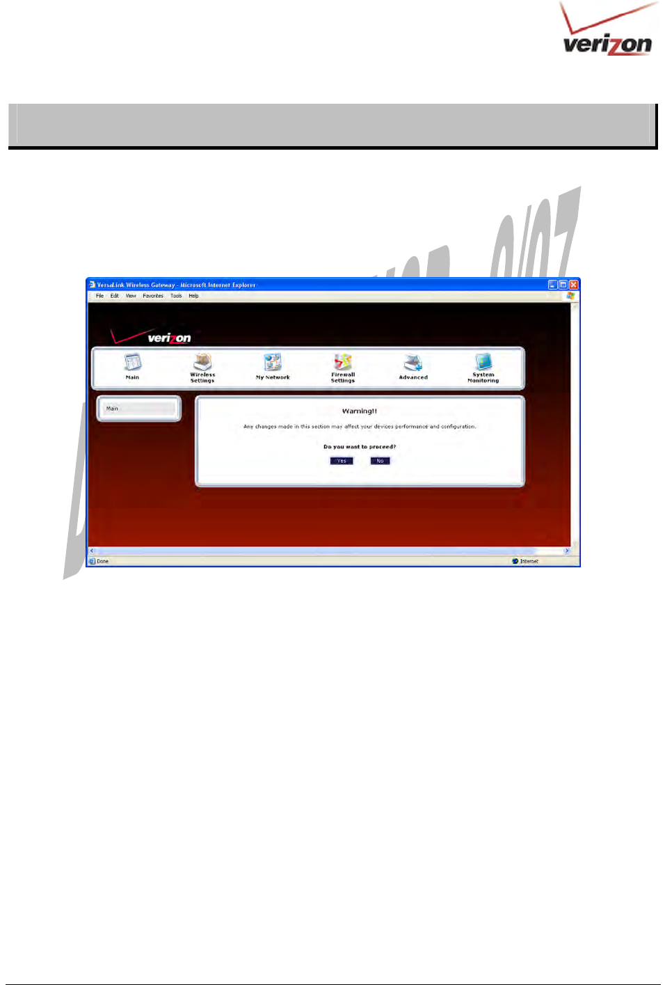
If you click System Monitoring in the top navigational menu, a warning screen will display the following message:
Any changes made in this section may affect your device’s performance and configuration.
Do you want to proceed?
Click Yes to proceed.
030-300536 Rev. A 167 August 2007
User GuideVersaLink Wireless Gatewa
y
(
Model 7500
)
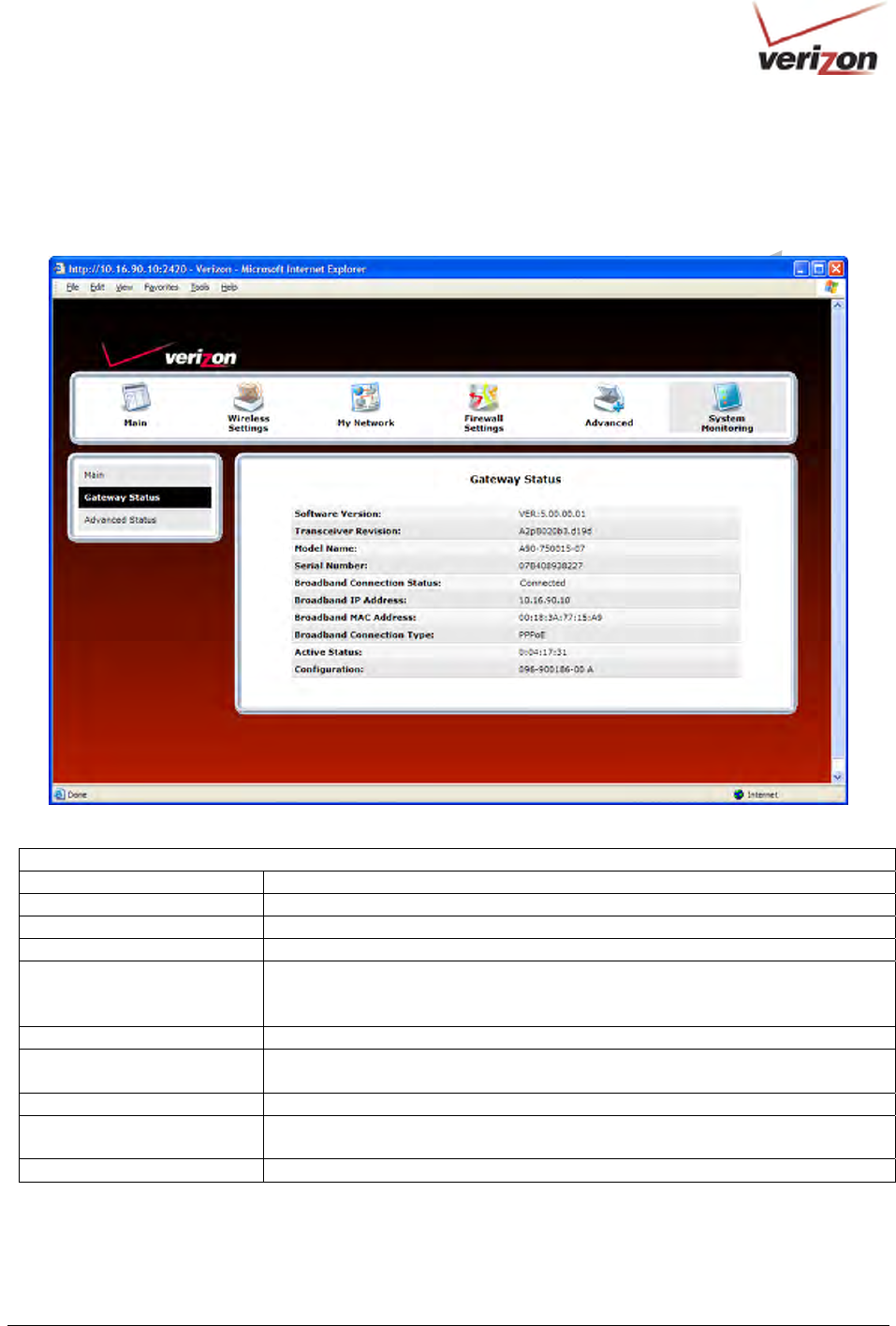
17.1 Gateway Status
If you clicked Yes in the warning screen, the following Gateway Status screen will appear. This screen allows you
to view details about your Router.
Gateway Status
Software Version VersaLink’s software version.
Transceiver Revision VersaLink’s transceiver version.
Model Name VersaLink manufacturer’s model name.
Serial Number VersaLink’s serial number.
Broadband Connection Status The status of your Internet connection.
Up = Internet connection established
Down = No Internet connection established
Broadband IP Address VersaLink’s WAN IP Address, assigned or provided by Verizon.
Broadband MAC Address Media Access Controller (MAC) i.e., hardware address of this device, assigned
by the manufacturer.
Broadband Connection Type The protocol used to establish an Internet connection with Verizon.
Active Status The duration that VersaLink has been in use (measured in hours: minutes:
seconds).
Configuration Proprietary configuration number for VersaLink.
030-300536 Rev. A 168 August 2007
User GuideVersaLink Wireless Gatewa
y
(
Model 7500
)
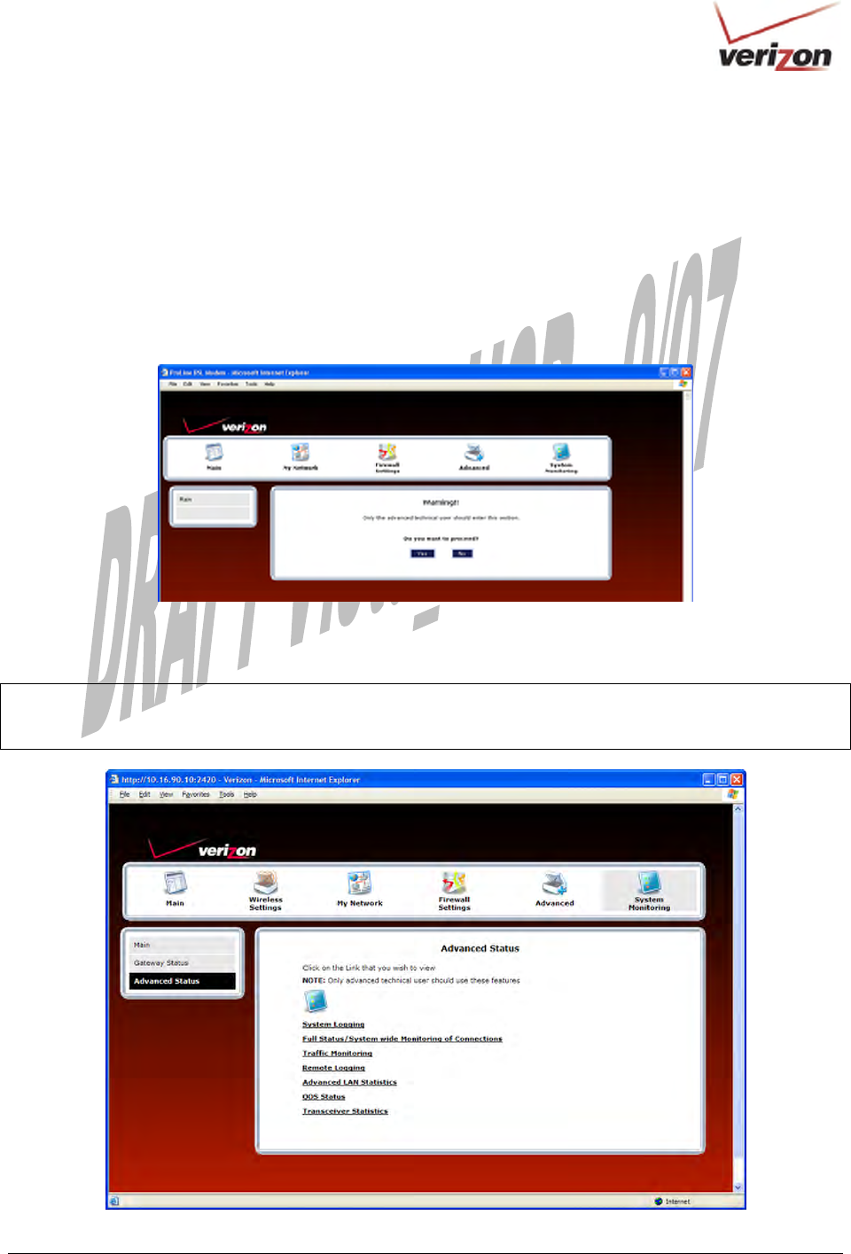
17.2 Advanced Status
If you select System Monitoring in the top navigational menu, and then click Advanced Status in the menu options
at the left of the screen, a warning screen will display the following message:
Any changes made in this section may affect your device’s performance and configuration.
Do you want to proceed?
Click Yes to proceed.
If you clicked Yes, in the Warning screen, the following screen will appear. From this screen, you can access
various logging and monitoring information recorded by your Router. Click the desired link to go to that screen.
NOTE: Only advanced users should use these features. If you need to reset the Router to factory default settings,
press the reset button on the rear of the Router. Or follow the instructions in section 16.2, “Restore Defaults,” to
restore the Router to factory default settings.
030-300536 Rev. A 169 August 2007
User GuideVersaLink Wireless Gatewa
y
(
Model 7500
)
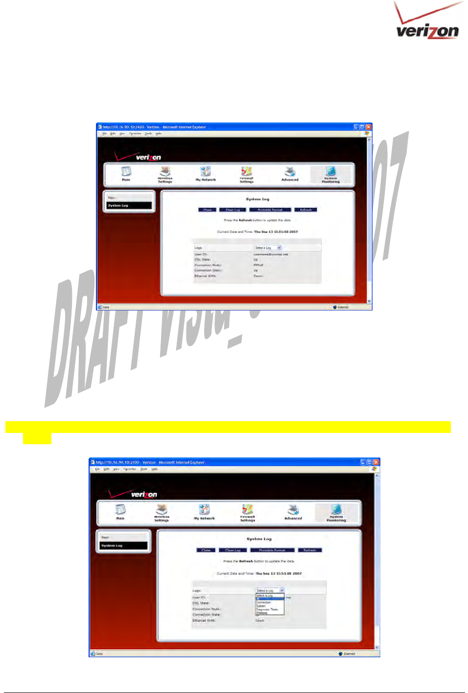
17.2.1 System Logging
In the Advanced Status screen, click System Logging. The following screen will be displayed.
At the Logs drop-down menu, do any of the following:
• Select All to list both Connection and System logs.
• Select Connection to list all events related to connection activity (any traffic on the USB, Ethernet, or DSL
ports).
• Select System to list all events related to system activity (Time, Errors, Boot Information, etc.)
• Select Diagnostic Tests to list all events related to the diagnostic logs
• Select Wireless to list all events related to the voice event logs [Shouldn’t this screen display “wireless event
logs”?]
030-300536 Rev. A 170 August 2007
User GuideVersaLink Wireless Gatewa
y
(
Model 7500
)
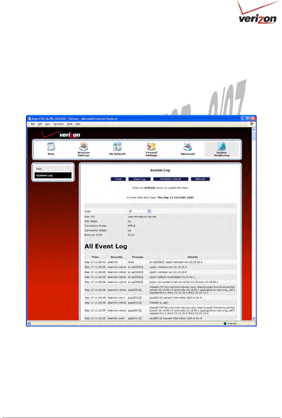
If you selected All from the Logs drop-down menu, the following screen will appear. You may need to scroll down
to the bottom of the logs screen to view all the logged events. After you have viewed the logs, do any of the
following:
• Click Close to close the logs page and to return to the Advanced Status screen.
• Click Clear Log to clear the logs screen.
• Click Printable Format to save a copy of the logs to a location on your computer.
• Click Refresh to update the logs screen so that it displays the most current information.
030-300536 Rev. A 171 August 2007
User GuideVersaLink Wireless Gatewa
y
(
Model 7500
)
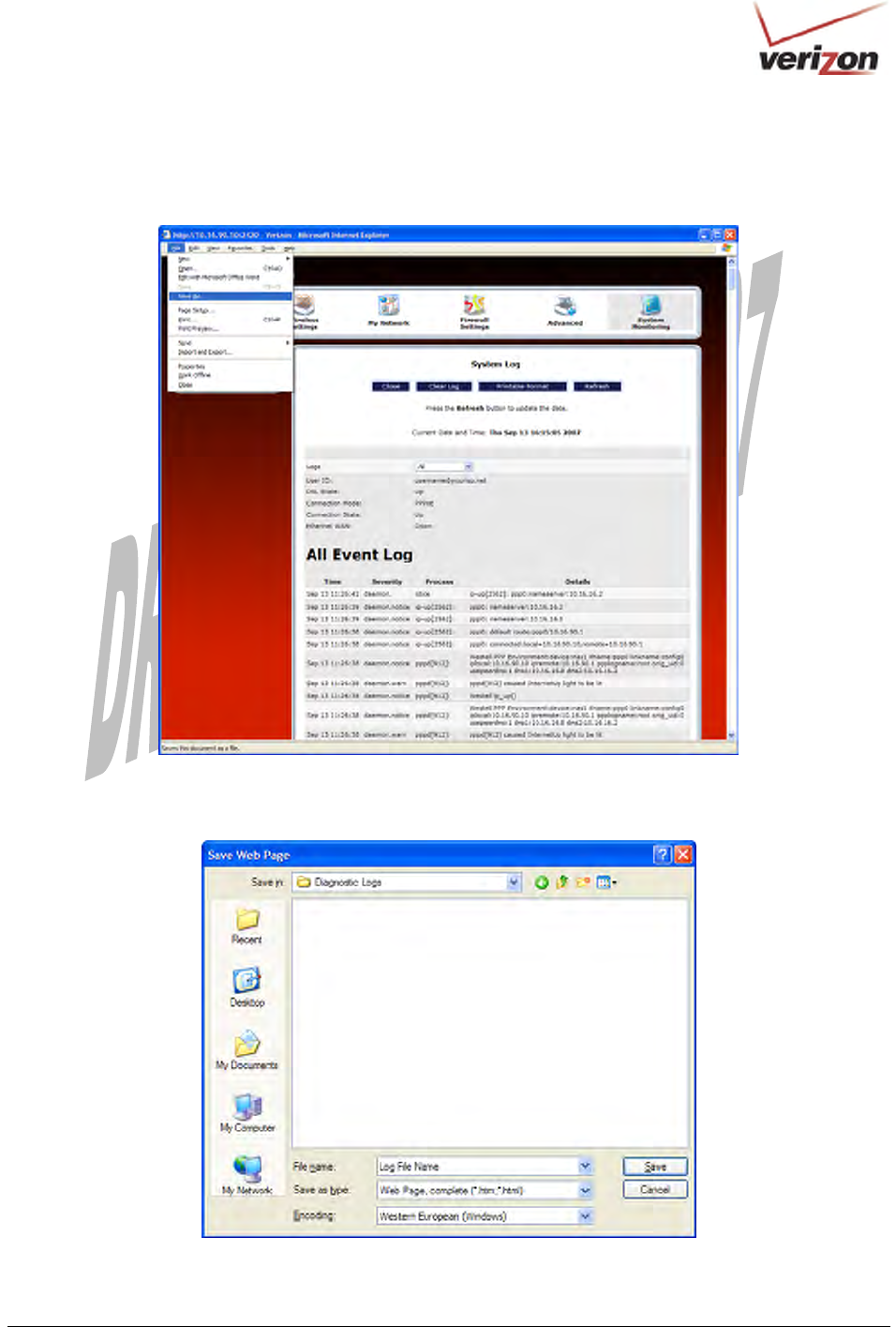
To save a copy of the logs to a location on your computer, in the System Log page, click Printable Format. The
following screen will appear. Click File > Save As from the menu options, and then save the file to the desired
location.
At the Save Web Page dialog box, select a destination for your log file from the Save in drop-down menu. Next,
enter a name for your log file in the field labeled File name, and then click Save to save the log file.
030-300536 Rev. A 172 August 2007
User GuideVersaLink Wireless Gatewa
y
(
Model 7500
)
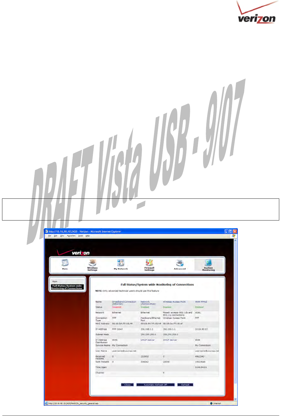
17.2.2 Full Status/System-wide Monitoring of Connections
In the Advanced Status screen, click Full Status/System-wide Monitoring of Connection. The following screen
will be displayed. After viewing the details of your Router’s connection, you can do any of the following:
• Click the Broadband Connection link to go to the VersaPort page and edit your broadband settings. Refer to
section 14.2.3 for additional details on this feature.
• Click the Network (Home/Office) link to go to the Private LAN DHCP page and edit your Private LAN
DHCP settings. Refer to section 16.18 for additional details on this feature.
• Click Wireless Access Point link to go to the Basic Security Settings page and edit your wireless settings.
Refer to section 13.3 for additional details on this feature.
• Click the WAN PPPoE link to go to the Advanced DSL Configuration page and edit your connection settings.
Refer to section 14.2.2 for additional details on this feature.
• Click the DHCP Server link to go to the Private LAN page and edit your Private LAN DHCP Server settings.
Refer to section 16.17 for additional details on this feature.
• Click the Close button to return to the Advanced Status screen.
• Click the Automatic Refresh Off/On button to turn on or turn off the screen’s automatic refresh feature.
• Click the Refresh button to manually refresh the screen.
NOTE: When the Automatic Refresh button displays Automatic Refresh Off, this means that the auto-refresh
feature is turned Off. Click the Automatic Refresh button to turn on automatic refresh. When the button displays
Automatic Refresh On, the page will refresh automatically.

030-300536 Rev. A 173 August 2007
User GuideVersaLink Wireless Gatewa
y
(
Model 7500
)
Full Status/System-wide Monitoring of Connections
Name A descriptor used to identify the Router’s connection type
Network (Home/Office)-Displays information about the Routers LAN connection
WAN PPPoE-Displays information about the Router’s WAN/Braodband connection
Status The status of the connection (Enabled/Disabled)
Network Ethernet- The the interface used to connect the Router to your LAN
xDSL - The interface used to connect to the Router to the WAN
Connection Type Hardware Ethernet Port- The physical connection type; the hardware used for the LAN
connection
PPP the virtual connection type; the protocol use for WAN/Braodband connection
MAC Address The Media Access Controller; the hardware address assigned to the deviced by the
manufacturer
IP Address The Router’s LAN and WAN/Braodband IP Addresses
Subnet Mask Displays the Router’s Subnet Mask, which determines what portion of an IP address is
controlled by the network and which portion is controlled by the host
IP Address Distribution The method by which IP address are allocated to devices on your LAN
Service Name The connection profile name to used to establish your Internet connection
User Name The user name (Account ID) used to identify you to Verizon and to establish your Internet
connection, provided by Verizon
Received Packets The number of packets received in to the Router’s LAN and WAN interfaces
Sent Packets The number of packets sent out from the Router’s LAN and WAN interfaces
Time Span The duration your PPP session has been connected (measured in hours: minutes: seconds)
Channel The channel of the wireless access point.
030-300536 Rev. A 174 August 2007
User GuideVersaLink Wireless Gatewa
y
(
Model 7500
)
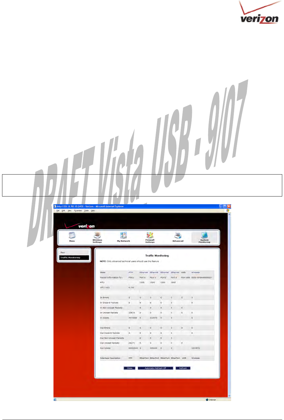
17.2.3 Traffic Monitoring
In the Advanced Status screen, click Traffic Monitoring. The following screen will be displayed. After viewing
your Router’s traffic details, you can do any of the following:
• Click the ATM link to go to the Advanced DSL Configuration page and edit your connection settings. Refer to
section 14.2.2 for additional details on this feature.
• Click the Ethernet link to go to the Private LAN DHCP page and edit your Private LAN DHCP settings. Refer
to section 16.18 for additional details on this feature.
• Click the Wireless link to go to the Basic Security Settings page and edit your wireless settings. Refer to
section 13.3 for additional details on this feature.
• Click the Close button to return to the Advanced Status screen.
• Click the Automatic Refresh Off/On button to turn on or turn off the screen’s automatic refresh feature.
• Click the Refresh button to manually refresh the screen.
NOTE: When the Automatic Refresh button displays Automatic Refresh Off, this means that the auto-refresh
feature is turned off. Click the Automatic Refresh button to turn on automatic refresh. When the button displays
Automatic Refresh On, the page will refresh automatically.
030-300536 Rev. A 175 August 2007
User GuideVersaLink Wireless Gatewa
y
(
Model 7500
)
Traffic Monitoring
Stats Represents the statistics for each interface type: ATM, Ethernet, or USB
Packet Information for The packet information for the interface.
VPI/VCI The VPI/VCI values obtained from Verizon.
In Errors The number of error packets received on the interface.
In Discard Packets The number of discarded packets received on the interface.
In Non Unicast Packets The number of non-Unicast packets received on the interface.
In Unicast Packets The number of Unicast packets received on the interface.
In Octets The number of bytes received on the interface.
Out Errors The number of outbound packets that could not be transmitted due to errors.
Out Discard Packets The number of outbound packets discarded.
Out Non Unicast Packets The number of non-Unicast packets transmitted on the interface.
Out Unicast Packets The number of Unicast packets transmitted on the interface.
Out Octets The number of bytes transmitted on the interface.
Interface Description A description field that refers to the interface type.
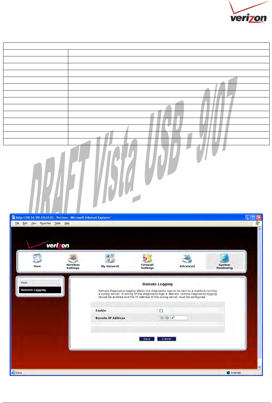
17.2.4 Remote Logging
In the Advanced Status screen, click Remote Logging. The following screen will be displayed. Remote diagnostics
logging allows the diagnostics logs to be sent to a machine running a syslog server.
To save the diagnostics logs, click the Enable box (a check mark will appear in the box). Next, type the IP address
of the syslog server in the Remote IP Address field. Click Save to save the settings.
030-300536 Rev. A 176 August 2007
User GuideVersaLink Wireless Gatewa
y
(
Model 7500
)
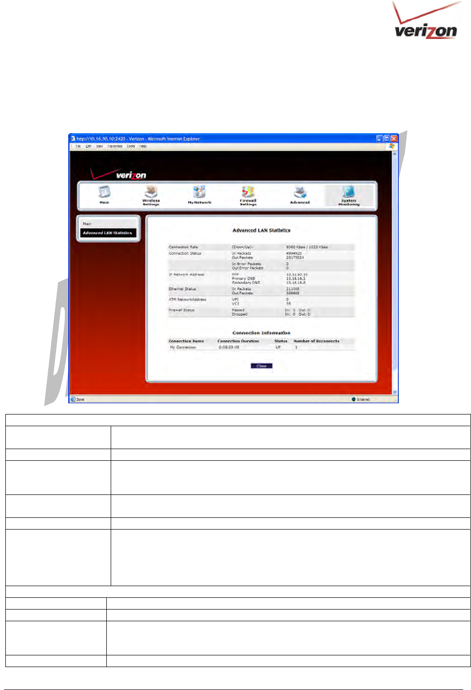
17.2.5 Advanced LAN Statistics
In the Advanced Status screen, click Advanced LAN Statistics. The following screen will be displayed. After you
have viewed the details in this page, click Close to return to the Advanced Status screen.
DSL Connection Information
Connection Rate This field will let you know if you have a DSL signal and the DSL rate at which you are
connected.
Connection Status This field will show how much information was received (IN) or sent (OUT) in packets.
IP Network Address PPP = An IP address identifies your device on the Internet
Primary DNS = Provided by your Service Provider
Secondary DNS = Provided by your Service Provider
Ethernet Status This field will display your Ethernet information that was received (IN) or sent (OUT) in
packets on your Ethernet port.
ATM Network Address This field will display your VPI and VCI values, which are provided by your ISP.
Firewall Status This field will display your firewall traffic in packets.
Passed: Monitors information traffic that was successfully received (IN) or transmitted
(OUT) in packets.
Dropped: Monitors information traffic that was not successfully received (IN) or
transmitted (OUT) due to your firewall settings.
PPP Connection Information
Connection Name This is from the connection profile that you established in section 8.
Connection Duration This field will display how long your PPP session has been connected.
Status This field will display the status of your PPP session.
UP=Connected
DOWN=Disconnected
Number of Reconnects This field will display the number of attempts that were made to establish a PPP session.
030-300536 Rev. A 177 August 2007
User GuideVersaLink Wireless Gatewa
y
(
Model 7500
)
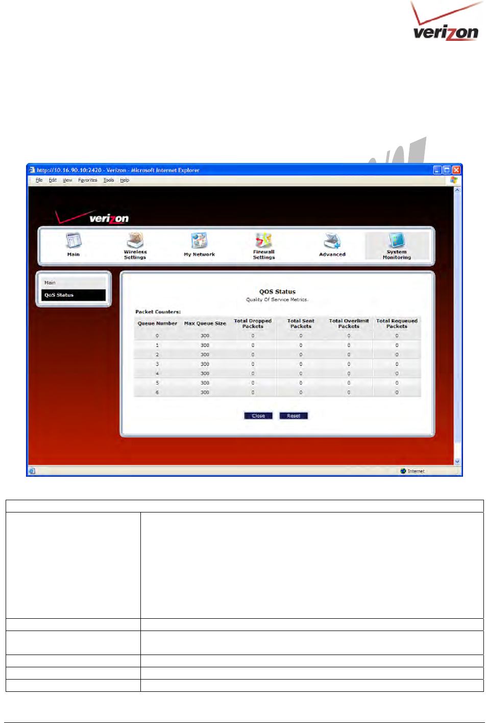
17.2.6 QOS Status
In the Advanced Status screen, click QOS Status. The following screen will be displayed. Click the Clear button
to clear all counts and statistics (not just latency counts). Clicking Clear does not affect the Router’s configuration.
(QOS must be enabled on the Router for this table to be populated.) After you have viewed the details in this page,
click Close to return to the Advanced Status screen.
QOS Status
Queue Number Indicates the DiffServ Queue.
Queue Number Descriptions:
0 = Best Effort (BE)
1 = Assured Forwarding 1 (AF1)
2 = Assured Forwarding 2 (AF2)
3 = Assured Forwarding 2 (AF3)
4 = Assured Forwarding 2 (AF4)
5 = Expedited Forwarding (EF)
6 = Routing Protocols (DiffServ priorities 6 and 7)
Max Queue Size The maximum number of packets that can be queued for this priority.
Total Dropped Packets Indicates how many packets of this priority have been dropped by QOS due to
lack of buffer space or filtering rules.
Total Sent Packets Displays the number of packets, destined for the WAN, that have been received.
Total Overlimit Packets Displays the current number of overlimit packets.
Total Requeued Packets Displays the most number of packets that have been requeued for this priority.
030-300536 Rev. A 178 August 2007
User GuideVersaLink Wireless Gatewa
y
(
Model 7500
)
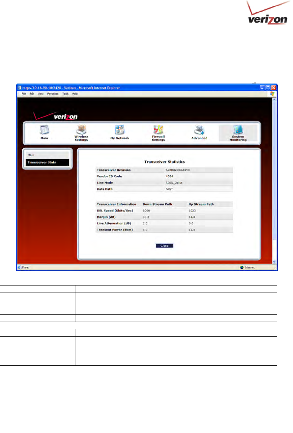
17.2.7 Transceiver Statistics
In the Advanced Status screen, click Transceiver Statistics. The following screen will be displayed. After you
have viewed the details in this page, click Close to return to the Advanced Status screen.
Transceiver Statistics
Transceiver Revision The transceiver software version number.
Vendor ID Code The CPE Vendor’s ID code for their chipset.
Line Mode The operational mode. Modes supported are No Mode, Multi Mode, T1.413
Mode, G.DMT Mode, and G.LITE Mode.
Data Path The data path used (either Fast or Interleaved).
Transceiver Information-Down Stream/Up Stream Path
DSL Speed (Kbits/Sec) The transmission rate that is provided by your service provider.
SNR Margin (dB) The Signal-to-Noise Ratio (S/N) where 0 db = 1x10⁻⁷, which inhibits your DSL
speed.
Line Attenuation (dB) The DSL line loss.
Transmit Power (dBm) The transmitted signal strength.
030-300536 Rev. A 179 August 2007
User GuideVersaLink Wireless Gatewa
y
(
Model 7500
)
18. PORT FORWARDING SERVICES
For your convenience, VersaLink supports protocols for Applications, Games, and VPN-specific programs. The
following chart provides port/protocol information for the supported services.
NOTE: To configure the Router for a service or application, follow the steps in section 15.3.3, “Configuring Port
Forwarding Services,” of this User Guide.
Applications/Games/VPN Support
Application/Game Port/Protocol
Aliens vs. Predator 80 UDP, 2300 UDP, 8000-8999 UDP
Age of Empires II: The
Conquerors
6073 UDP, 47624 TCP, 2300-2400 TCP/UDP
This service will open up ports for both traffic directions.
Americas Army TCP – 20045
UDP – 1716 to 1718, 8777, 27900
America Online 5190 TCP/UDP
Anarchy Online TCP/UDP – 7012,7013, 7500 -7505
AOL Instant Messenger 4099 TCP, 5190 TCP
Asheron's Call 9000-9013 UDP, 28800-29000 TCP
Battlecom 2300-2400 TCP/UDP, 47624 TCP/UDP
Battlefield 1942 UDP - 14567, 22000, 23000 to 23009, 27900, 28900
Black and White 2611-2612 TCP, 6667 TCP, 6500 UDP, 27900 UDP
Blizzard Battle.net (Diablo II) 4000 TCP, 6112 TCP/UDP
Buddy Phone 700, 701 UDP
Bungie.net, Myth, Myth II Server 3453 TCP
Calista IP Phone 3000 UDP, 5190 TCP
Citrix Metaframe 1494 TCP
Client POP/IMAP 110 TCP
Client SMTP 25 TCP
Counter Strike 27015 TCP/UDP, 27016 TCP/UDP
Dark Reign 2 26214 TCP/UDP
Delta Force ( Client and Server ) 3568 UDP, 3100-3999 TCP/UDP
Delta Force 2 3568-3569 UDP
DeltaForce: Land Warrior UDP 53
TCP 21
TCP 7430
TCP 80
UDP 1029
UDP 1144
UDP 65436
UDP 17478
DNS 53 UDP
Elite Force 2600 UDP, 27500 UDP, 27910 UDP, 27960 UDP
Everquest 1024-7000 TCP/UDP
F-16, Mig 29 3863 UDP
F-22 Lightning 3 4660-4670 TCP/UDP, 3875 UDP, 4533-4534 UDP, 4660-4670 UDP
F-22 Raptor 3874-3875 UDP
Fighter Ace II 50000-50100 TCP/UDP
Fighter Ace II for DX play 50000-50100 TCP/UDP, 47624 TCP, 2300-2400 TCP/UDP
FTP 20 TCP, 21 TCP

030-300536 Rev. A 180 August 2007
User GuideVersaLink Wireless Gatewa
y
(
Model 7500
)
GameSpy Online UDP 3783
UDP 6515
TCP 6667
UDP 12203
TCP/UDP 13139
UDP 27900
UDP 28900
UDP 29900
UDP 29901
Ghost Recon TCP 80
UDP 1038
UDP 1032
UDP 53
UDP 2347
UDP 2346
GNUtella 6346 TCP/UDP, 1214 TCP
Half Life Server 27005 UDP(client only)
27015 UDP
Heretic II Server 28910 TCP
Hexen II 26900 (+1) each player needs their own port. Increment by one for
each person.
Hotline Server 5500, 5503 TCP 5499 UDP
HTTPS 443 TCP/UDP
ICMP Echo 4 ICMP
ICQ OLD 4000 UDP, 20000-20019 TCP
ICQ 2001b 4099 TCP, 5190 TCP
ICUII Client 2000-2038 TCP, 2050-2051 TCP, 2069 TCP, 2085 TCP, 3010-3030
TCP
ICUII Client Version 4.xx 1024-5000 TCP, 2050-2051 TCP, 2069 TCP, 2085 TCP, 3010-3030
TCP, 2000-2038 TCP6700-6702 TCP, 6880 TCP, 1200-16090 TCP
IMAP 119 TCP/UDP
IMAP v.3 220 TCP/UDP
Internet Phone 22555 UDP
IPSEC ALG IPSEC ALG
IPSEC ESP PROTOCOL 50
IPSEC IKE 500 UDP
Ivisit 9943 UDP, 56768 UDP
JKII:JO (Jedi Knight II: Jedi
Outcast)
UDP - 28070 (default)
UDP- 27000 to 29000
KALI, Doom & Doom II 2213 UDP, 6666 UDP (EACH PC USING KALI MUST USE A
DIFFERENT PORT NUMBER STARTING WITH 2213 + 1)
KaZaA 1214 TCP/UDP
Limewire 6346 TCP/UDP, 1214 TCP
Medal Of Honor: Allied Assault TCP 80
UDP 53
UDP 2093
UDP 12201
TCP 12300
UDP 2135
UDP 2139
TCP/UDP 28900
mIRC Chat 6660-6669 TCP
Motorhead Server 16000 TCP/UDP, 16010-16030 TCP/UDP
030-300536 Rev. A 181 August 2007
User GuideVersaLink Wireless Gatewa
y
(
Model 7500
)
MSN Game Zone 6667 TCP, 28800-29000 TCP
MSN Game Zone (DX 7 & 8 play) 6667 TCP, 6073 TCP, 28800-29000 TCP, 47624 TCP, 2300-2400
TCP/UDP This service will open up ports for both traffic directions.
MSN Messenger 6891-6900 TCP, 1863 TCP/UDP, 5190 UDP, 6901 TCP/UDP
Napster 6699 TCP
Need for Speed 3, Hot Pursuit 1030 TCP
Need for Speed, Porsche 9442 UDP
Net2Phone 6801 UDP
NNTP 119 TCP/UDP
Operation FlashPoint 47624 UDP, 6073 UDP, 2300-2400 TCP/UDP, 2234 TCP
Outlaws 5310 TCP/UDP
Pal Talk 2090-2091 TCP/UDP, 2095 TCP, 5001 TCP, 8200-8700 TCP/UDP,
1025-2500 UDP
pcAnywhere host 5631 TCP, 5632 UDP, 22 UDP
Phone Free 1034-1035 TCP/UDP, 9900-9901 UDP, 2644 TCP, 8000 TCP
Quake 2 27910 UDP
Quake 3 27660 UDP
Each computer playing QuakeIII must use a different port number,
starting at 27660 and incrementing by 1. You'll also need to do the
following:
1. Right click on the QIII icon
2. Choose "Properties"
3. In the Target field you'll see a line like "C:\Program Files\Quake
III Arena\quake3.exe"
4. Add the Quake III net_port command to specify a unique
communication port for each system. The complete field should look
like this: "C:\Program Files\Quake III Arena\quake3.exe" +set
net_port 27660
5. Click OK.
6. Repeat for each system behind the NAT, adding one to the
net_port selected (27660,27661,27662)
Quicktime 4/Real Audio 6970-32000 UDP, 554 TCP/UDP
Rainbow Six & Rogue Spear 2346 TCP
RealOne Player TCP - 554, 7070 to 7071
UDP - 6970 to 7170
Real Audio 6970-7170 UDP
Return To Castle Wolfenstein Default -27960 TCP/UDP
UDP - 27950 to 27980
Roger Wilco TCP/UDP 3782
UDP 3783 (BaseStation)
SIP ALG SIP ALG
ShoutCast Server 8000-8005 TCP
Spinner Radio/Netscape Music TCP - 554
SSH Secure Shell 22 TCP/UDP
Starcraft 2346 TCP
Starfleet Command 2300-2400 TCP/UDP, 47624 TCP/UDP
SOF/SOFII (Soldier of Fortune /
Soldier of Fortune II)
UDP - 28910 to 28915
Telnet 23 TCP
Tiberian Sun & Dune 2000 1140-1234, 4000 TCP/UDP
Tribes2 TCP - 15104, 15204, 15206, 6660 to 6699
UDP - 27999 to 28002
Ultima Online 5001-5010 TCP, 7775-7777 TCP, 8800-8900 TCP, 9999 UDP, 7875

030-300536 Rev. A 182 August 2007
User GuideVersaLink Wireless Gatewa
y
(
Model 7500
)
UDP
Unreal Tournament server 7777 (default gameplay port)
7778 (server query port)
7779,7779+ are allocated dynamically for each helper UdpLink
objects, including UdpServerUplin objects. Try starting with 7779-
7781 and add ports if needed.
27900 server query, if master server uplink is enabled. Home master
servers use other ports like 27500.
Port 8080 is for UT Server Admin. In the [UWeb.WebServer]
section of the server.ini file, set the ListenPort to 8080 and
ServerName to the IP assigned to the Gateway from Verizon.
USENET News Service 143 TCP
VNC, Virtual Network Computing 5500 TCP, 5800 TCP, 5900 TCP
Westwood Online, C&C 4000 TCP/UDP, 1140-1234 TCP/UDP
World Wide Web (HTTP) 80 TCP
443 TCP (SSL)
8008 or 8080 TCP (PROXY)
Xbox Live 88 TCP/UDP, 3074 TCP/UDP
Yahoo Messenger Chat 5000-5001 TCP
Yahoo Messenger Phone 5055 UDP
NAT/VPN Support
IPSec Encryption IPSec using AH can not be supported through NAT. IPSec using
ESP and L2TP can be supported via an ALG
L2TP IPSec using ESP and L2TP can be supported via an ALG.
PPTP Works through NAT.

030-300536 Rev. A 183 August 2007
User GuideVersaLink Wireless Gatewa
y
(
Model 7500
)
19. TECHNICAL SUPPORT INFORMATION
Contact your Internet service provider for technical support.
20. PRODUCT SPECIFICATIONS
System Requirements for 10/100 Base-T/Ethernet
• Pentium® or equivalent class machines or
higher
• Microsoft® Windows® (Vista™, XP,
2000, ME, NT 4.0, 98 SE) Macintosh®
OS X, or Linux installed
• 64 MB RAM (128 MB recommended)
• 10 MB of free hard drive space
• 10/100 Base-T Network Interface Card
(NIC)
• Internet Explorer 5.5 or higher or
Netscape Navigator 7.x or higher
• Computer Operating System CD-ROM
System Requirements for USB
• Pentium® or equivalent class machines or
higher
• Microsoft® Windows® (Vista™, XP,
2000, ME, 98 SE) installed
• 64 MB RAM (128 MB recommended)
• 10 MB of free hard drive space
• USB Version 1.1 or higher compliant bus
• Internet Explorer 5.5 or higher or
Netscape Navigator 7.x or higher
• Computer operating system CD-ROM
System Requirements for Wireless
• Pentium® or equivalent class machines or
higher
• Microsoft® Windows® (Vista™, XP,
2000, ME, 98 SE) installed
• 64 MB RAM (128 MB recommended)
• 10 MB of free hard drive space
• USB Version 1.1 or higher compliant bus
• Internet Explorer 5.5 or higher or
Netscape Navigator 7.x or higher
• Computer operating system CD-ROM
• IEEE 802.11b/g PC adapter
LEDs
• Power
• E1, E2, E3, E4
• Wireless
• USB
• DSL
• Internet
Connectors
• DSL: 6-pin RJ-11 modular jack-DSL
• USB: 4-pin Type B connector
• Ethernet: 8-pin RJ-45 modular jack
• Power: Barrel connector
Power
• Power Supply: External 120 VAC (10%) to
12 VDC wall-mount power supply
• Power Consumption: Less than 8 watts
typical, from 120 VAC
Dimensions
• Height: 1.3 in. (3.30 cm)
• Width: 7.0 in (17.78 cm)
• Depth: 4.9 in. (12.44 cm)
Weight
• Approx. 1 lb (0.45 kg)
Environmental
• Ambient Operating Temperature: +32 to
+104 °F (0 to +40 °C)
• Relative Humidity: 5 to 95%, non-condensing
EMC/Safety/Regulatory Certifications
• FCC Part 15, Class B
• ANSI/UL Standard 60950-1
• CAN/CSA Standard C22.2 No. 60950-01
First Edition dated
• UL, CSA, ACTA 968-A-3
• Industry Canada CS03

030-300536 Rev. A 184 August 2007
User GuideVersaLink Wireless Gatewa
y
(
Model 7500
)
21. SOFTWARE LICENSE AGREEMENT
READ THE TERMS AND CONDITIONS OF THIS LICENSE AGREEMENT CAREFULLY. THIS
SOFTWARE IS COPYRIGHTED AND LICENSED (NOT SOLD). BY INSTALLING AND OPERATING
THIS PRODUCT, YOU ARE ACCEPTING AND AGREEING TO THE TERMS OF THIS LICENSE
AGREEMENT. IF YOU ARE NOT WILLING TO BE BOUND BY THE TERMS OF THIS LICENSE
AGREEMENT, YOU SHOULD PROMPTLY RETURN THE SOFTWARE AND HARDWARE TO
WESTELL TECHNOLOGIES, INC. THIS LICENSE AGREEMENT REPRESENTS THE ENTIRE
AGREEMENT CONCERNING THE SOFTWARE BETWEEN YOU AND WESTELL TECHNOLOGIES,
INC. (REFERRED TO AS "LICENSOR"), AND IT SUPERSEDES ANY PRIOR PROPOSAL,
REPRESENTATION, OR UNDERSTANDING BETWEEN THE PARTIES.
1. License Grant. Licensor hereby grants to you, and you accept, a nonexclusive license to use the Compact
Disk (CD) and the computer programs contained therein in machine-readable, object code form only
(collectively referred to as the "SOFTWARE"), and the accompanying User Documentation, only as
authorized in this License Agreement. The SOFTWARE may be used only in connection with the number of
systems for which you have paid license fees as dictated in your support agreement. You agree that you will
not assign, sublicense, transfer, pledge, lease, rent, or share your rights under this License Agreement. You
agree that you may not nor allow others to reverse assemble, reverse compile, or otherwise translate the
SOFTWARE.
You may retain the SOFTWARE CD for backup purposes only. In addition, you may make one copy of the
SOFTWARE in any storage medium for backup purposes only. You may make one copy of the User's
Manual for backup purposes only. Any such copies of the SOFTWARE or the User's Manual shall include
Licensor's copyright and other proprietary notices. Except as authorized under this paragraph, no copies of
the SOFTWARE or any portions thereof may be made by you or any person under your authority or control.
2. Licensor's Rights. You acknowledge and agree that the SOFTWARE and the User's Manual are
proprietary products of Licensor protected under U.S. copyright law. You further acknowledge and agree
that all right, title, and interest in and to the SOFTWARE, including associated intellectual property rights,
are and shall remain with Licensor. This License Agreement does not convey to you an interest in or to the
SOFTWARE, but only a limited right of use revocable in accordance with the terms of this License
Agreement.
3. License Fees. The fees paid by you under the support agreement are paid in consideration of the licenses
granted under this License Agreement.
4. Term. This License Agreement is effective upon your opening of this package and shall continue until
terminated. You may terminate this License Agreement at any time by returning the SOFTWARE and all
copies thereof and extracts there from to Licensor. Licensor may terminate this License Agreement upon the
breach by you of any term hereof. Upon such termination by Licensor, you agree to return to Licensor the
SOFTWARE and all copies and portions thereof.
5. Limitation of Liability. Licensor's cumulative liability to you or any other party for any loss or damages
resulting from any claims, demands, or actions arising out of or relating to this Agreement shall not exceed
the license fee paid to Licensor for the use of the SOFTWARE. In no event shall Licensor be liable for any
indirect, incidental, consequential, special, or exemplary damages or lost profits, even if Licensor has been
advised of the possibility of such damages. SOME STATES DO NOT ALLOW THE LIMITATION OR
EXCLUSION OF LIABILITY FOR INCIDENTAL OR CONSEQUENTIAL DAMAGES, SO THE ABOVE
LIMITATION OR EXCLUSION MAY NOT APPLY TO YOU.

030-300536 Rev. A 185 August 2007
User GuideVersaLink Wireless Gatewa
y
(
Model 7500
)
6. Governing Law. This License Agreement shall be construed and governed in accordance with the laws of
the State of Illinois. You submit to the jurisdiction of the state and federal courts of the state of Illinois and
agree that venue is proper in those courts with regard to any litigation arising under this Agreement.
7. Costs of Litigation. If any action is brought by either party to this License Agreement against the other
party regarding the subject matter hereof, the prevailing party shall be entitled to recover, in addition to any
other relief granted, reasonable attorney fees and expenses of litigation.
8. Severability. Should any term of this License Agreement be declared void or unenforceable by any court of
competent jurisdiction, such declaration shall have no effect on the remaining terms hereof.
9. No Waiver. The failure of either party to enforce any rights granted hereunder or to take action against
the other party in the event of any breach hereunder shall not be deemed a waiver by that party as to
subsequent enforcement of rights or subsequent actions in the event of future breaches.

030-300536 Rev. A 186 August 2007
User GuideVersaLink Wireless Gatewa
y
(
Model 7500
)
22. PUBLICATION INFORMATION
Verizon® VersaLink™ Wireless Gateway (Model 7500)
Document Part Number 030-300536 Rev. A
© 2007 Verizon
All rights reserved.
All trademarks and registered trademarks are the property of their respective owners.