Contents
- 1. User Manual Part One
- 2. User Manual Part Three
- 3. User Manual Part Two a
- 4. User Manual Part Two b
User Manual Part Two a
030-300536 Rev. A 68 August 2007
User GuideVersaLink Wireless Gatewa
y
(
Model 7500
)
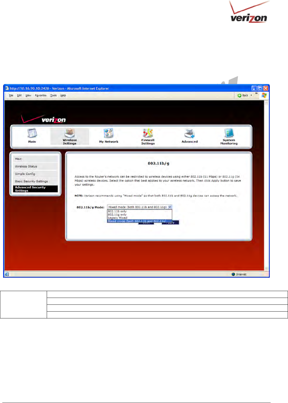
13.4.4 802.11b/g Mode
If you select the 802.11b/g Mode link in the Advanced Security Settings screen, the following screen will be
displayed. This screen allows you to limit access to your Router based on technology type. From the drop-down
menu, select the desired setting. Then, click Apply to allow the settings to take effect.
11b only: Communication with VersaLink is limited to 802.11b
11g only: Communication with VersaLink is limited to 802.11g
Legacy Mixed: Communication with VersaLink is limited to 802.11b/g
802.11b/g Mode
Mixed mode: Computers using 802.11b or 802.11g technology can communicate with VersaLink.
030-300536 Rev. A 69 August 2007
User GuideVersaLink Wireless Gatewa
y
(
Model 7500
)
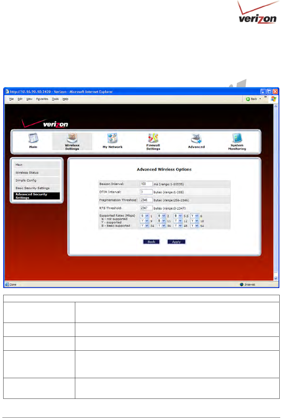
13.4.5 Other Advanced Wireless Options
If you select the Other Advanced Wireless Options link in the Advanced Security Settings screen, the following
screen will appear. From the drop-down menus, select the desired settings. Then, click Apply to allow the settings to
take effect.
Wireless Advanced Configuration
Beacon Interval The time interval between beacon frame transmissions. Beacons contain rate and
capability information. Beacons received by stations can be used to identify the
access points in the area.
DTIM Interval The number of Beacon intervals between DTIM transmissions. Multicast and
broadcast frames are delivered after every DTIM
Fragmentation Threshold Any MSDU or MPDU larger than this value will be fragmented into an MPDU of
the specified size.
RTS Threshold RTS/CTS handshaking will be performed for any data or management MPDU
containing a number of bytes greater than the threshold. If this value is larger than
the MSDU size (typically set by the fragmentation threshold), no handshaking will
be performed. A value of zero will enable handshaking for all MPDUs.
Supported Rates (Mbps)
802.11b Rates (Mbps)
802.11g Rates (Mbps)
These are the allowable communication rates that VersaLink will attempt to use.
The rates are also broadcast within the connection protocol as the rates supported
by VersaLink.
030-300536 Rev. A 70 August 2007
User GuideVersaLink Wireless Gatewa
y
(
Model 7500
)
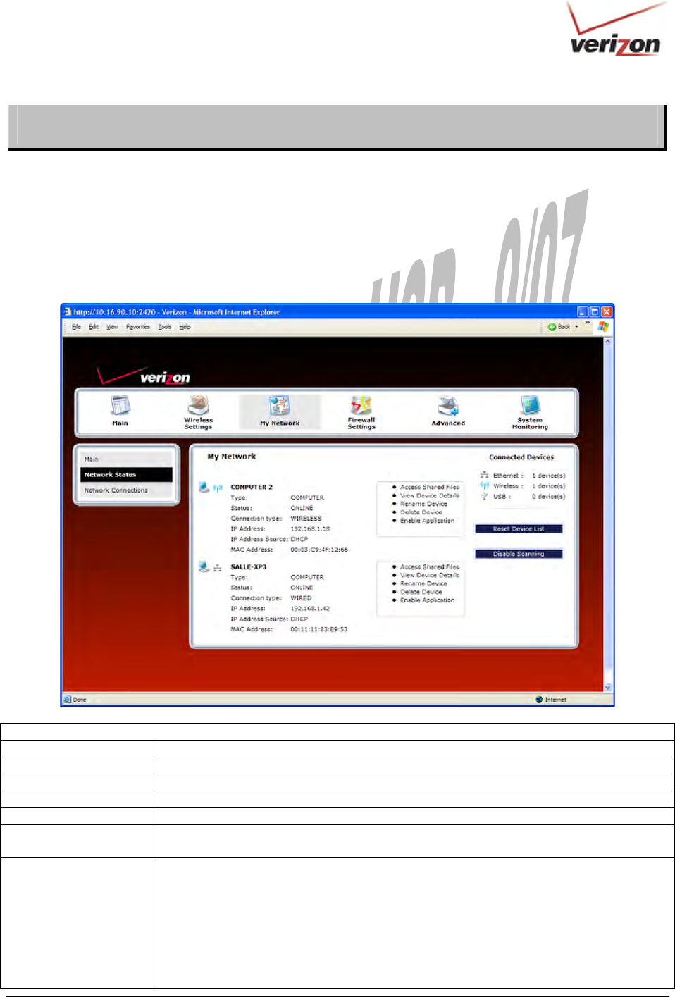
14. MY NETWORK
This section discusses details about your Router’s network.
14.1 Network Status
To view your Router’s network settings, from the top navigational menu, select My Network. Next, click Network
Status in the submenu at the left of the screen. The following screen will appear. This screen displays information
about the devices connected to your local area network (LAN).
My Network
Type The type of device connected to your network
Status The connection status for the device.
Connection Type The physical connection used to interface with your Router.
IP Address The IP address assigned to your computer.
IP Address Source The method by which your computer receives its IP address.
MAC Address The Media Access Controller; the hardware address assigned to the deviced by the
manufacturer.
Connected Devices The interfaces used to connect to your Router to the computer.
Ethernet: Displays the number of devices that are connected to the Router via Ethernet
10/100 BaseT connection.
Wireless: Displays the number of devices that are connected to the Router wirelessly.
USB: Displays the number of devices that are connected to the Router via USB
connection.
Note: If you have computers on your network that are not being displayed, check the
firewall setting on the PCs to ensure that the firewall is disabled.
030-300536 Rev. A 71 August 2007
User GuideVersaLink Wireless Gatewa
y
(
Model 7500
)
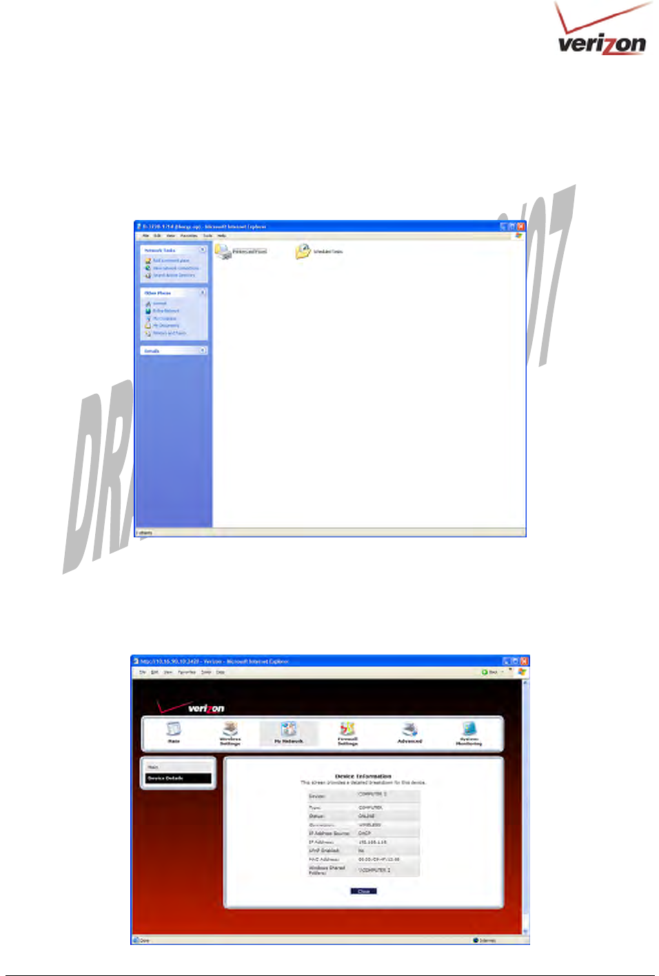
14.1.1 Access Shared Files
In the My Network panel, click the Access Shared Files link to access files from a device on your local network.
(The device from which you will access files must have file sharing enabled.) If the device has a firewall turned on,
you will not be able to access shared files from the device.
14.1.2 View Device Details
In the My Network panel, click the View Device Details link to view details about your device. After you have
finished viewing this screen, click Close to return to the My Network page.
030-300536 Rev. A 72 August 2007
User GuideVersaLink Wireless Gatewa
y
(
Model 7500
)
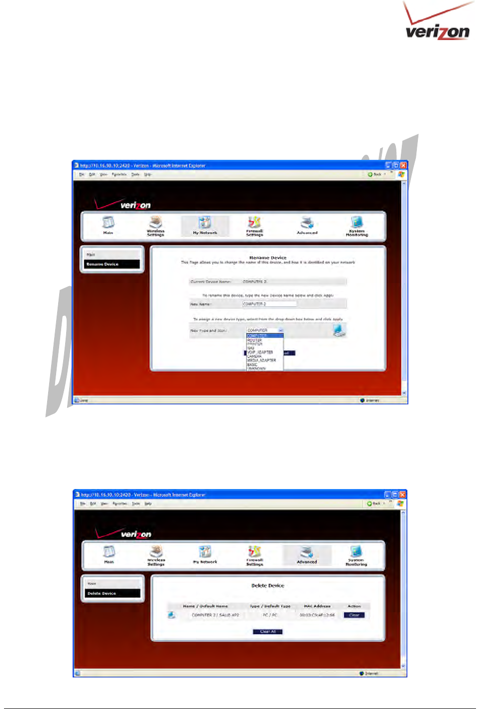
14.1.3 Rename Device
In the My Network panel, click the Rename Device link to rename a device on your network. In the following
screen, type the desired name in the New Name box, and then (if desired) select an icon from the New Icon drop-
down menu to assign a different icon to this device. Next, click the Rename Device button to allow the changes to
take effect. Click Back to return to the My Network panel.
14.1.4 Delete Device
In the My Network panel, click the Delete Device link to remove a device from your network. Click the Clear button next
to the device that you want to remove from your network, or click Clear All to remove all devices from your network.
030-300536 Rev. A 73 August 2007
User GuideVersaLink Wireless Gatewa
y
(
Model 7500
)
14.1.5 Enable Application
In the My Network panel, click the Enable Application link to set up applications for your service profile. This
feature enables applications (Games, Webcams, IM & Others) by opening a tunnel between remote (Internet)
computers and a specific device port inside your local area network (LAN). Details on this screen will be discussed
later in section 15.3, “Port Forwarding.”
030-300536 Rev. A 74 August 2007
User GuideVersaLink Wireless Gatewa
y
(
Model 7500
)
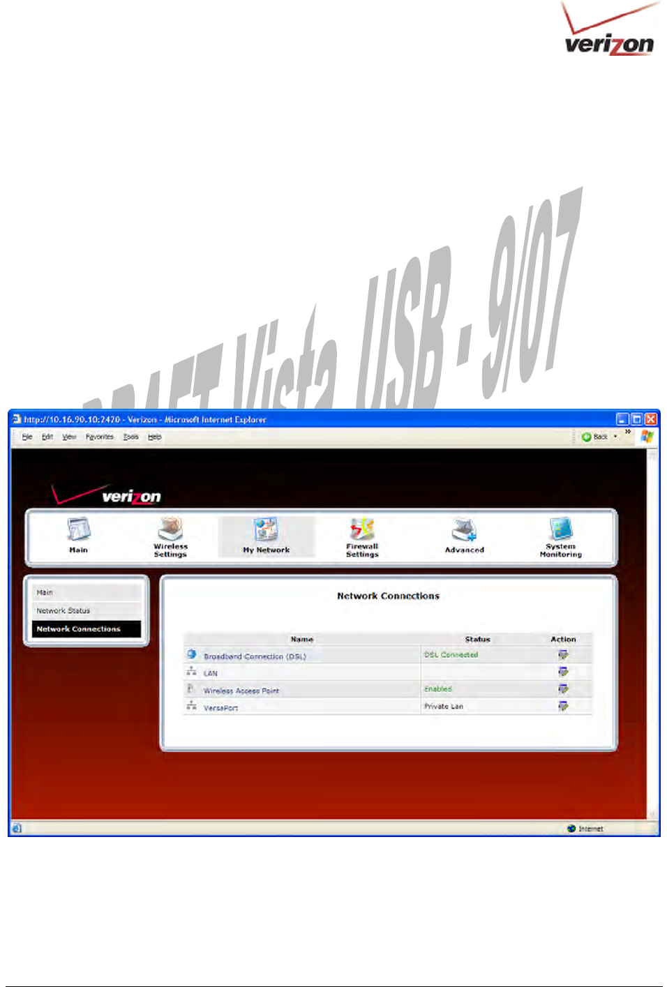
14.2 Network Connections
To edit your connection settings, from the top navigational menu select My Network. Next, select Network
Connections in the submenu options at the left of the screen; the following screen will be displayed. This screen
allows you to access your Router’s connection settings and your local area network (LAN) settings. The following
sections discuss the details of this screen.
• To access the Router’s Broadband connection settings, in the Network Connections screen click the
Broadband Connection (DSL) link. The Basic DSL Configuration screen will appear. Refer to section 14.2.1
for details about this feature.
• To access the Router’s LAN settings, in the Network Connections screen click the LAN link. The Private
LAN screen will appear. Refer to section 16.18 for details about this feature.
• To access the Router’s Wireless settings, in the Network Connections screen, click the Wireless Access Point
link. Refer to section 13.3 for details about this feature.
• To access the Router’s Uplink settings, in the Network Connections screen, click the VersaPort link. Refer to
section 14.2.3 for details about this feature.
030-300536 Rev. A 75 August 2007
User GuideVersaLink Wireless Gatewa
y
(
Model 7500
)
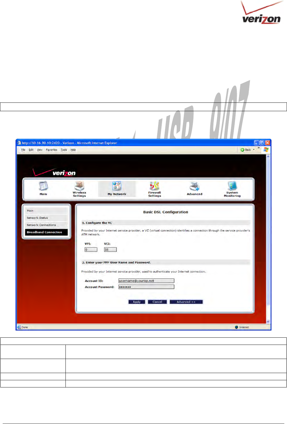
14.2.1 Basic DSL Configuration
If you clicked the Broadband Connection (DSL) link in the Network Connections screen, the following screen
will appear. This screen displays the virtual connection (VC) settings and the account information needed to
authenticate your Internet connection. A virtual connection identifies a connection through the service provider’s
ATM network to Verizon. Unlike physical hardware connections, virtual connections are defined by data. The
VPI/VCI and account parameters are provided by Verizon.
IMPORTANT: You should not change the VPI/VCI settings unless instructed by Verizon.
If you change any settings in this screen, click Apply to allow the settings to take effect. To access the Advanced
DSL Configuration screen, click the Advanced button.
Basic DSL Configuration
VPI Displays the VPI (Virtual Path Indicator) value for a particular VC, which is defined by
Verizon.
VCI Displays the VCI (Virtual Channel Indicator) value for a particular VC, which is defined
by Verizon.
Account ID The account ID is provided by Verizon.
Account Password The account password is provided by Verizon.
030-300536 Rev. A 76 August 2007
User GuideVersaLink Wireless Gatewa
y
(
Model 7500
)
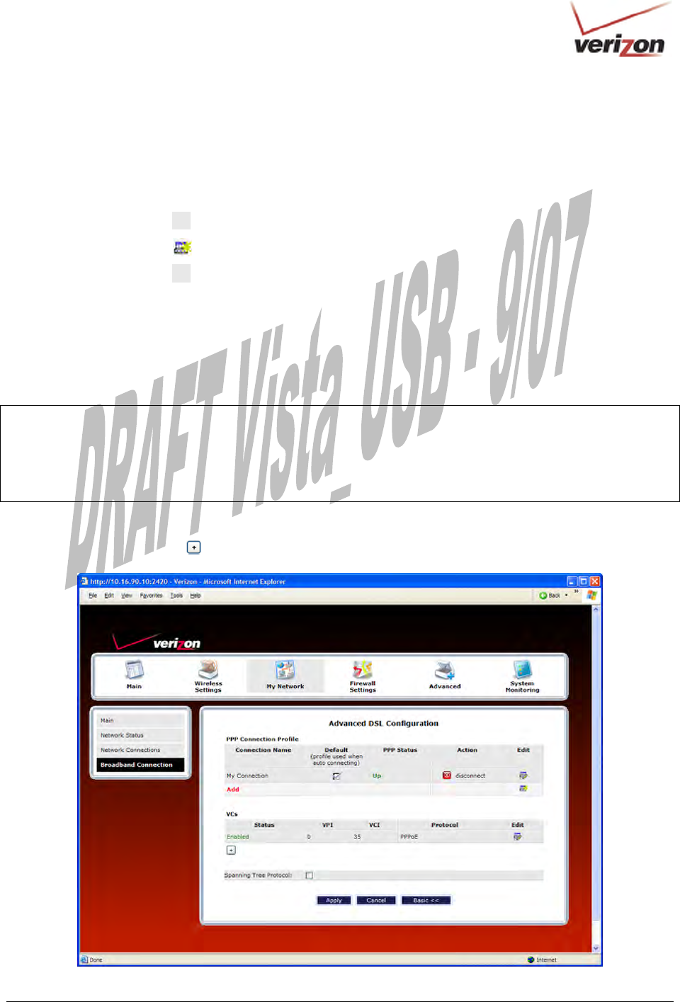
14.2.2 Advanced DSL Configuration
If you clicked Advanced in the preceding screen, the following Advanced DSL Configuration screen will appear.
Depending on the connection settings you want to edit, you can:
• Click the Edit icon adjacent to My Connection to edit your connection profile settings.
• Click the New icon (or click Add) to add a new connection profile.
• Click the Edit icon in the VCs section to edit your virtual connection (VC) settings.
14.2.2.1 Editing VC Protocol Settings
The following sections discuss your virtual connection (VC) settings. A virtual connection (VC) identifies a
connection through the service provider’s ATM network to Verizon.
IMPORTANT:
1. The screens displayed in the following sections reflect the Router when it is configured for LAN Ethernet port
mode, which is the Router’s factory default setting. For details on configuring the Router’s VC settings while in
WAN Uplink port mode, refer to section 14.2.3, “Configuring VersaPort.”
2. You should not change the VC settings unless instructed by Verizon.
If you change any settings in this screen, you must click Apply to allow the settings to take effect. To expand the
VCs list, click the expand icon located below Status.

030-300536 Rev. A 77 August 2007
User GuideVersaLink Wireless Gatewa
y
(
Model 7500
)
VC Settings
Status Allows you to enable or disable your VC (Virtual Connection). This field must
display “Enable” in order to allow edits to the VC settings.
VPI Displays the VPI (Virtual Path Indicator) value for a particular VC, which is
defined by your Service Provider.
VCI Displays the VCI (Virtual Channel Indicator) value for a particular VC, which
is defined by your Service Provider.
Protocol
NOTE: The configuration
specified by your Service
Provider will determine which
Protocols are available to you.
Displays the Protocol for each VC, which is specified by your Service
Provider.
Possible Responses:
PPPoA = Point to Point Protocol over ATM (Asynchronous Transfer Mode)
PPPoE = Point to Point Protocol over Ethernet
Bridge = Bridge Protocol
Classical IPoA = Internet Protocol over ATM (Asynchronous Transfer Mode).
This is an ATM encapsulation of the IP protocol.
Bridge Broadcast
Factory Default = Enabled (box contains a check mark)
When this setting is enabled, the Router will allow Broadcast IP packets
to/from the WAN.
When this setting is disabled (box is cleared), the Router will block Broadcast
IP packets to/from the WAN.
Bridge Broadcast is only valid if one of the Virtual Channels is configured for
Bridge mode.
Bridge Multicast Factory Default = Enabled
When this setting is disabled, the Router will block Multicast IP packets
to/from the WAN.
When this setting is enabled, the Router will allow Multicast IP packets
to/from the WAN.
Bridge Multicast is only valid if one of the Virtual Channels is configured for
Bridge mode.
Spanning Tree Protocol Factory Default = Disabled
Spanning Tree Protocol is a link management protocol that provides path
redundancy while preventing undesirable loops in the network. For Ethernet
network to function properly, only one active path can exist between two
stations.
When enabled, two bridges are used to interconnect the same two computer
network segments. Spanning Tree Protocol will allow the bridges to exchange
information so that only one of them will handle a given message that is being
sent between two computers within the network.
030-300536 Rev. A 78 August 2007
User GuideVersaLink Wireless Gatewa
y
(
Model 7500
)
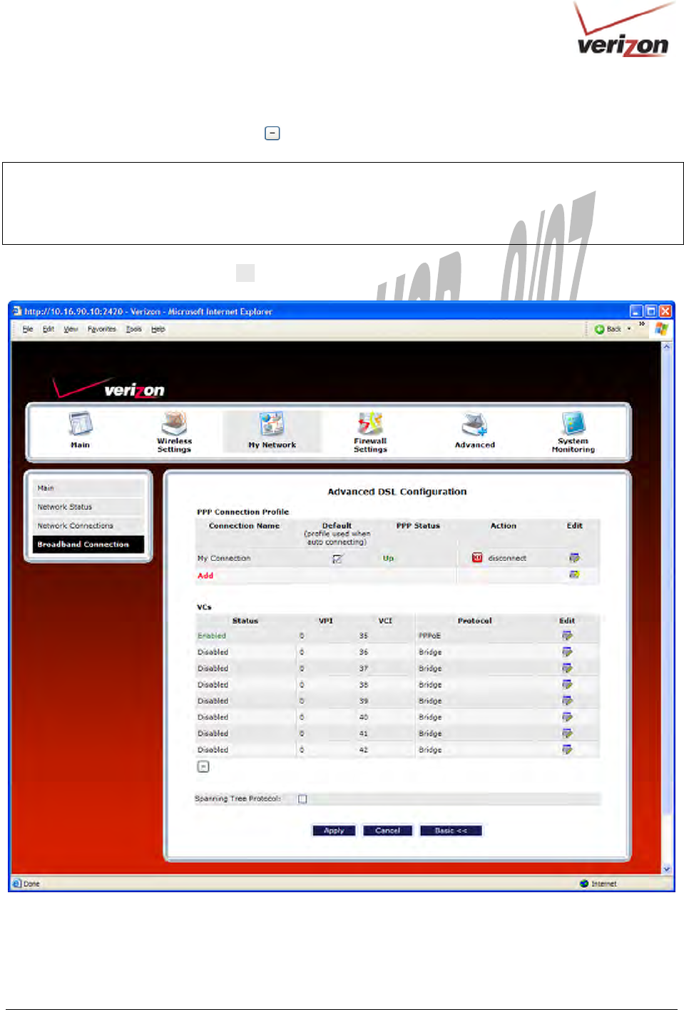
If you clicked the expand icon in the preceding screen, the following screen will appear. When you are ready to
collapse the VCs list, click the collapse icon .
NOTE:
1. A VC’s Status field must display Enabled before you can edit its VC settings.
2. The actual values displayed in the following screen may vary, depending on the network connection established. If
you have questions about the settings in this screen, please contact Verizon.
To edit a VC setting, click the edit icon adjacent to the “Enabled” VC protocol that you want to edit.
030-300536 Rev. A 79 August 2007
User GuideVersaLink Wireless Gatewa
y
(
Model 7500
)
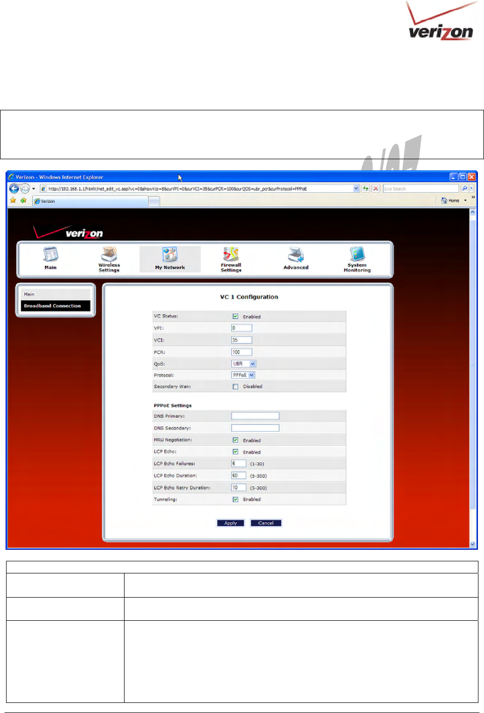
The following table explains the settings in the VC 1 Configuration screen. If you change any VC settings in this
screen, click Apply to save the settings.
NOTE: If you experience problems, reset the Router via the hardware reset button at the rear of the Router. Or
follow the instructions in section 16.2, “Restore Defaults,” to restore the Router to factory default settings.
After the Router has been reset, the values in the screens will display the factory default settings, and any settings
that you have previously configured will be discarded.
VC 1 Configuration
VPI This field allows you to change your VPI (Virtual Path Indicator) value for a
particular VC, which is defined by your Service Provider.
VCI This field allows you to change your VCI (Virtual Channel Indicator) value for a
particular VC, which is defined by your Service Provider.
PCR Factory Default = 100%
Peak Cell Rate (PCR)-The maximum rate at which cells can be transmitted across a
virtual circuit, specified in cells per second and defined by the interval between the
transmission of the last bit of one cell and the first bit of the next.
This value is a percentage of the current data rate.
100 allows this VC to use 100% of the available bandwidth.
80 allows this VC to use 80% of the available bandwidth.

030-300536 Rev. A 80 August 2007
User GuideVersaLink Wireless Gatewa
y
(
Model 7500
)
QoS Quality of Service, which is determined by your Service Provider.
Possible Responses:
CBR = Constant Bit Rate
UBR = Unspecified Bit Rate
VBR = Variable Bit Rate
Protocol The Protocol for each VC, which is specified by your Service Provider.
Possible Responses:
PPPoA = Point to Point Protocol over ATM (Asynchronous Transfer Mode)
PPPoE = Point to Point Protocol over Ethernet
Bridge = Bridge Protocol
Classical IPoA = Internet Protocol over ATM (Asynchronous Transfer Mode). This
is an ATM encapsulation of the IP protocol.
Status The protocol status.
PPPoE / PPPoA Settings
IP Address Displays the IP network address that your Router is on.
Gateway Displays the Router’s IP address
DNS Primary Provided by Verizon
DNS Secondary Provided by Verizon
MRU Negotiation Factory Default = Disabled
If Enabled, the Maximum Received Unit (MRU) would enforce MRU negotiations.
Note: Enable this option only at your Internets provider’s request.
LCP Echo Disable Factory Default = Disabled
If checked, this option will disable the modem LCP Echo transmissions.
LCP Echo Failures Indicates number of continuous LCP echo non-responses received before the PPP
session is terminated.
LCP Echo Duration The interval between LCP Echo transmissions with responses.
LCP Echo Retry Duration The interval between LCP Echo after no response.
Tunneling Factory Default = Enable
If Enabled, this option allows PPP traffic to be bridged to the WAN. This feature
allows you to use a PPPoE shim on the host computer to connect to the Internet
Service Provider, by bypassing the Router’s capability to do this.
Note: Tunneling is available in PPPoE mode only.
Note: The values for the IP Address, Gateway, DNS Primary, and DNS Secondary are all “Override of the value
obtained from the PPP connection,” They default to “0.0.0.0,” in which case the override is ignored. It is
recommended that you do not change the values unless your Internet service provider instructs you to do so.
030-300536 Rev. A 81 August 2007
User GuideVersaLink Wireless Gatewa
y
(
Model 7500
)
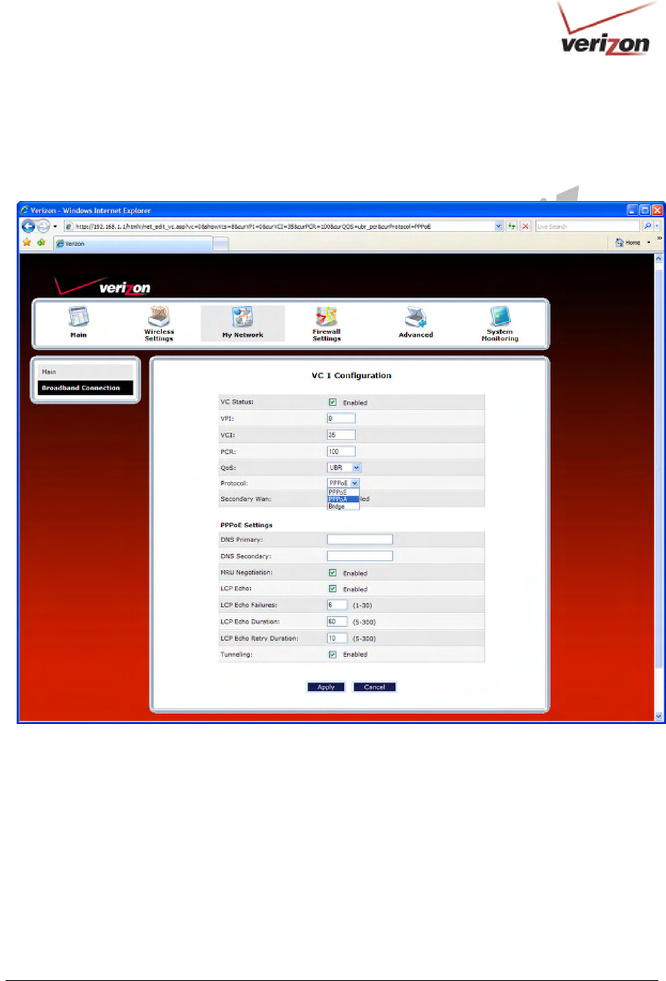
14.2.2.2 Configuring the Router’s Protocol Settings for PPPoE or PPPoA
To configure the Router’s protocol settings for PPPoE or PPPoA, access to the VC 1 Configuration screen, as
explained earlier in section 14.2.2.1 “Editing VC Protocol Settings.” At the VC 1 Configuration screen, select PPPoE
or PPPoA from the Protocol drop-down menu.
030-300536 Rev. A 82 August 2007
User GuideVersaLink Wireless Gatewa
y
(
Model 7500
)
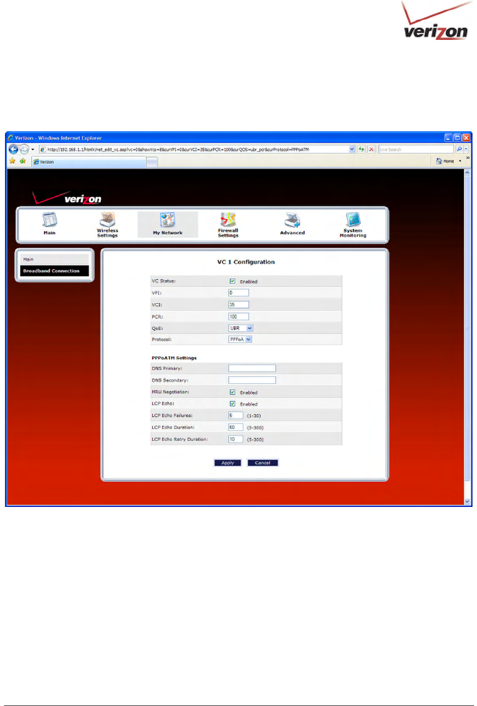
For example, the following VC 1 Configuration screen displays PPPoA as the selected Protocol. The PPPoA and
PPPoE screens have identical configuration options with the exception of the Tunneling feature. Tunneling is available
only for PPPoE protocol and is not displayed when the Router is configured for PPPoA protocol. After you have made
the appropriate changes to VC 1 Configuration screen, click Apply to continue.
030-300536 Rev. A 83 August 2007
User GuideVersaLink Wireless Gatewa
y
(
Model 7500
)
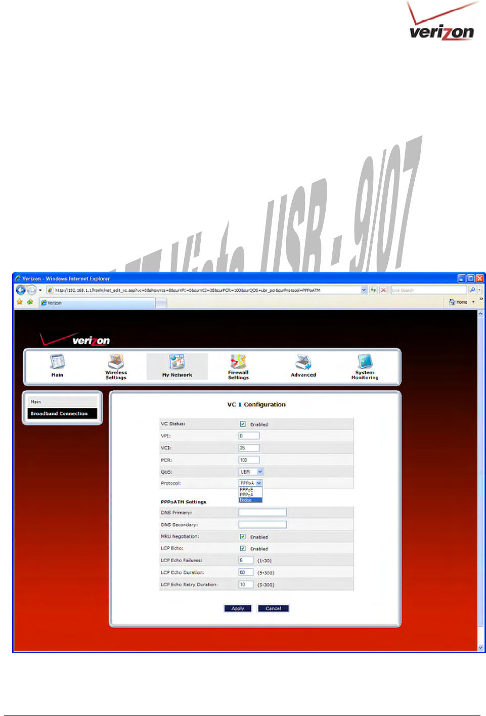
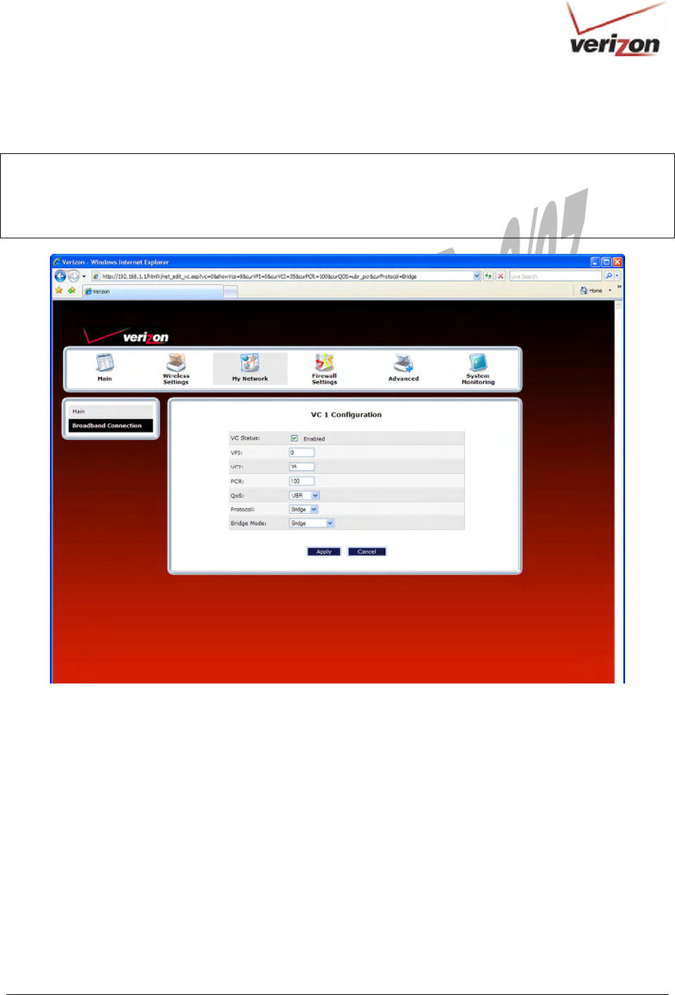
14.2.2.3 Configuring the Router’s Protocol Settings for Bridge
To configure the Router’s protocol settings for Bridge, access the VC 1 Configuration screen, as explained earlier in
section 14.2.2.1, “Editing VC Protocol Settings.”
To configure the Router’s Bridge settings, follow these steps at the VC 1 Configuration screen:
1. Select Bridge in the Protocol drop-down menu.
2. Select the desired Bridge mode from Bridge Mode drop-down menu.
3. Enter the desired values in the fields provided (if requested).
4. Click Apply to save your settings.
5. Click OK in the pop-up screen to reset the Router.
For example, at the VC 1 Configuration screen, select Bridge from the Protocol drop-down menu.
030-300536 Rev. A 84 August 2007
User GuideVersaLink Wireless Gatewa
y
(
Model 7500
)
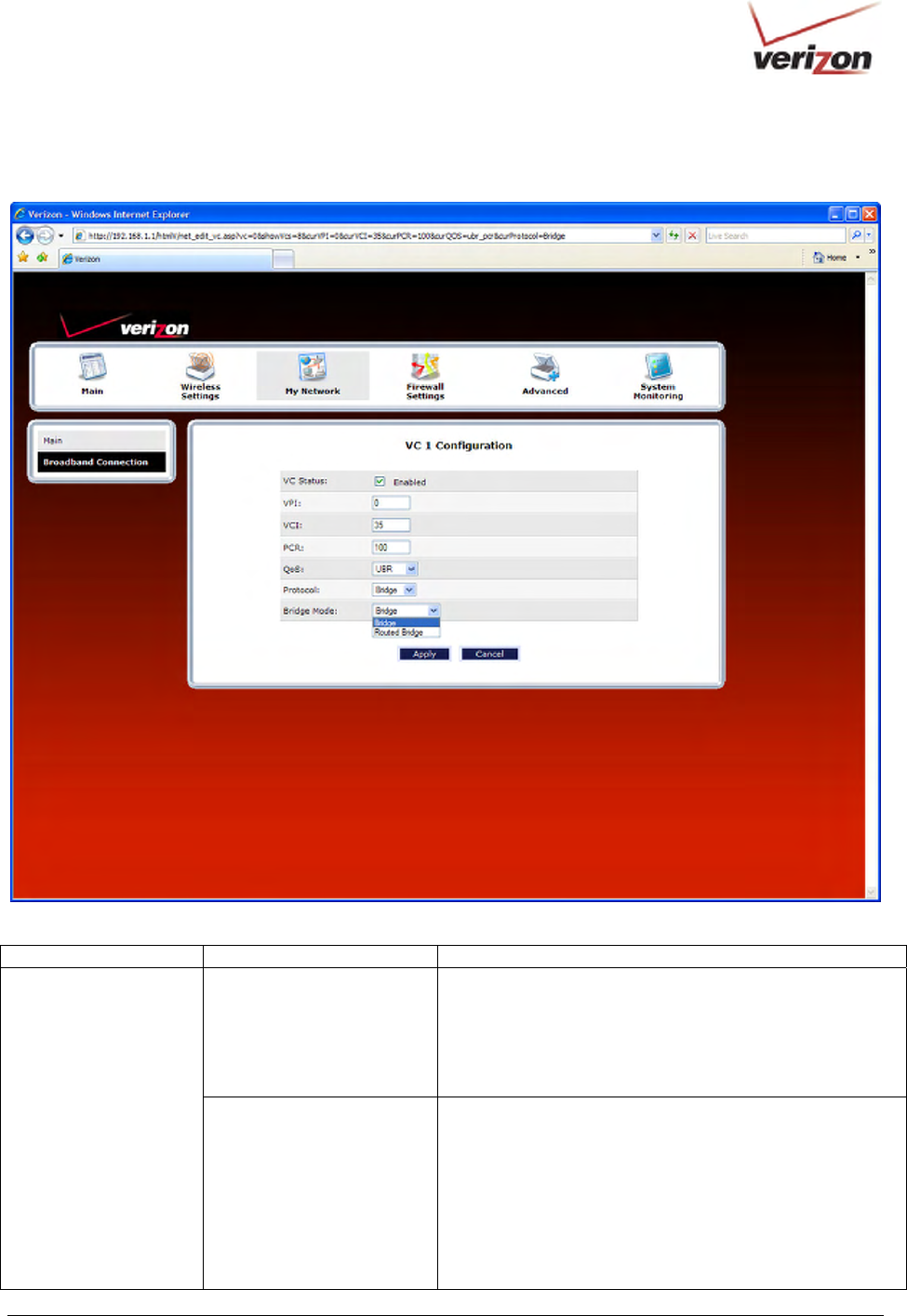
The following screen will appear. Bridge settings are described in the following table.
Protocol Mode Description
Bridge
A bridge is a layer 2 device that connects two segments of
the same LAN that use the same protocol such as Ethernet.
The modem does not have a WAN IP address in this mode.
The client PC will typically get an IP address from a DHCP
server in the network or the IP address can be assigned to
the client PC statically.
Bridge
Routed Bridge
Routed Bridged Encapsulation (RBE) is the process by
which a bridged segment is terminated on a routed
interface. Specifically, the Router is routing on an IEEE
802.3 or Ethernet header carried over RFC 1483 bridged
ATM. RBE was developed to address the known RFC1483
bridging issues, including broadcast storms and security.
The modem will get a WAN IP address through DHCP or
can be assigned statically. NAT will use the global address
assigned to the modem.
030-300536 Rev. A 85 August 2007
User GuideVersaLink Wireless Gatewa
y
(
Model 7500
)
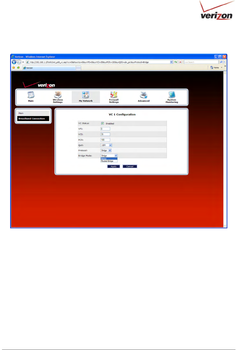
Next, select the desired Bridge mode from Bridge Mode drop-down menu.

030-300536 Rev. A 86 August 2007
User GuideVersaLink Wireless Gatewa
y
(
Model 7500
)
VC 1 – Bridge Protocol (Bridge Mode)
VC Status The protocol status is Enabled.
VPI This setting allows you to change your VPI (Virtual Path Indicator) value for a
particular VC, which is defined by your Service Provider.
VCI This setting allows you to change your VCI (Virtual Channel Indicator) value for a
particular VC, which is defined by your Service Provider.
PCR Factory Default = 100%
Peak Cell Rate (PCR)-The maximum rate at which cells can be transmitted across a
virtual circuit, specified in cells per second and defined by the interval between the
transmission of the last bit of one cell and the first bit of the next.
This value is a percentage of the current data rate.
100 allows this VC to use 100% of the available bandwidth.
80 allows this VC to use 80% of the available bandwidth.
QoS Quality of Service, which is determined by your Service Provider.
Possible Responses:
CBR = Constant Bit Rate
UBR = Unspecified Bit Rate
VBR = Variable Bit Rate
Protocol The Protocol for each VC, which is specified by your Service Provider.
Possible Responses:
PPPoA = Point to Point Protocol over ATM (Asynchronous Transfer Mode)
PPPoE = Point to Point Protocol over Ethernet
Bridge = Bridge Protocol
Bridge
A bridge is a layer 2 device that connects two segments of the
same LAN that use the same protocol such as Ethernet. The
modem does not have a WAN IP address in this mode. The client
PC will typically get an IP address from a DHCP server in the
network or the IP address can be assigned to the client PC
statically.
Bridge Mode
Routed Bridge
Routed Bridged Encapsulation (RBE) is the process by which a
bridged segment is terminated on a routed interface. Specifically,
the Router is routing on an IEEE 802.3 or Ethernet header carried
over RFC 1483 bridged ATM. RBE was developed to address the
known RFC1483 bridging issues, including broadcast storms and
security. The modem will get a WAN IP address through DHCP
or can be assigned statically. NAT will use the global address
assigned to the modem.
030-300536 Rev. A 87 August 2007
User GuideVersaLink Wireless Gatewa
y
(
Model 7500
)
If you select Bridge as the Protocol, and then select Bridge from the Bridge Mode drop-down menu, the following
screen will appear. Click Apply to save your selection.
IMPORTANT: If you configure the Router to use Bridge protocol and Bridge Mode, you must disable the Router’s
DHCP server. By disabling the DHCP server and using Bridge protocol (Bridge mode), you will allow the computer
to receive its IP address directly from the ISP’s DHCP server, not from the Router’s DHCP server. For instructions
on disabling the Router’s DHCP server, see section 16.17, “IP Address Distribution.” After you have disabled the
Router’s DHCP server, you must reboot the computer to allow the change to take effect.
030-300536 Rev. A 88 August 2007
User GuideVersaLink Wireless Gatewa
y
(
Model 7500
)
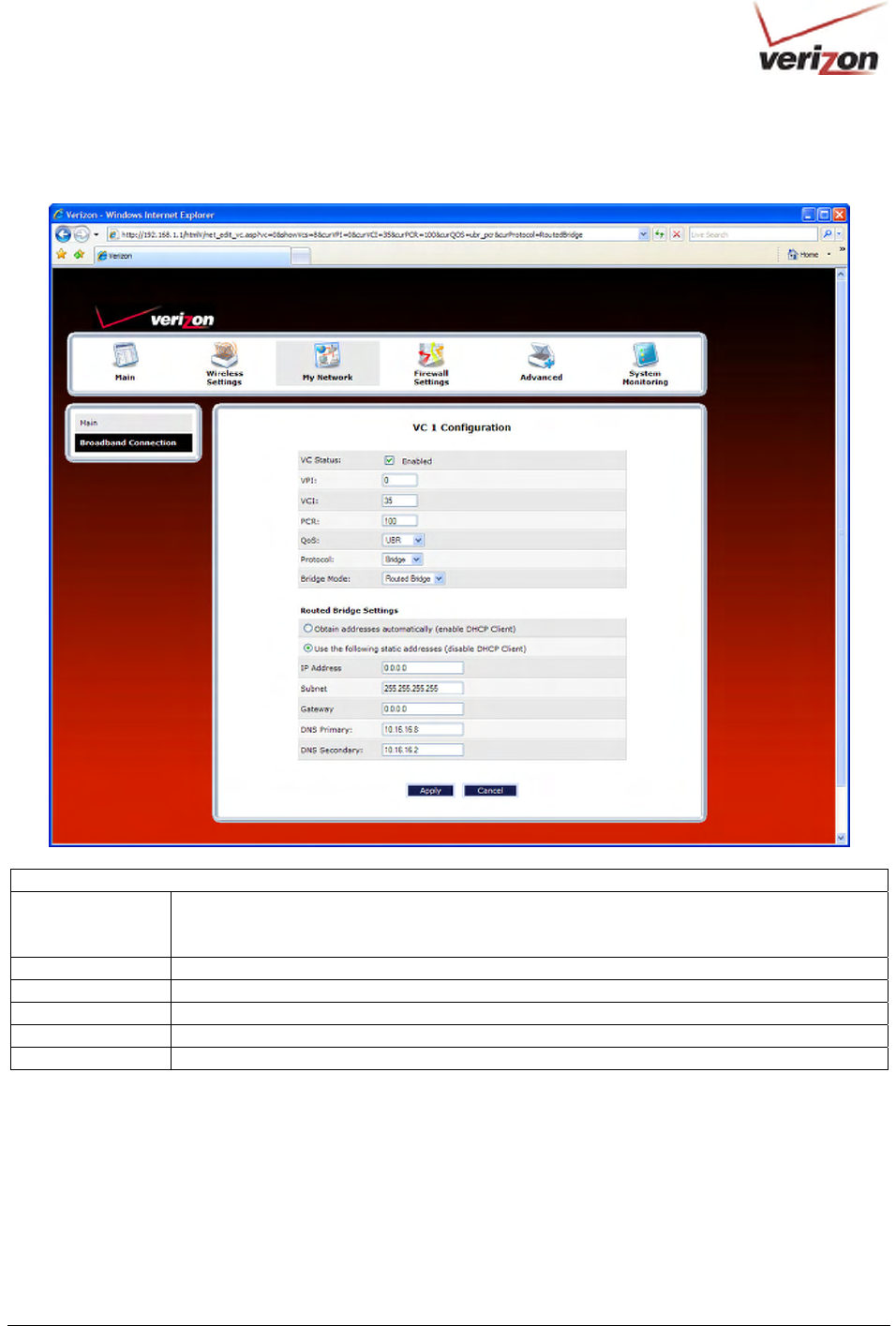
If you select Bridge as the Protocol, and then select Routed Bridge from the Bridge Mode drop-down menu, the
following screen will appear. Enter the desired values in the fields provided, and then click Apply.
VC 1 – Bridge Protocol (Routed Bridge Mode)
DHCP Client Allows you to either Enable or Disable the DHCP Client.
Select (enable DHCP Client) to obtain IP address automatically.
Select (disable DHCP Client) to use the static IP address that you enter into fields provided.
IP Address The IP network address that your Router is on.
Subnet Mask The subnet mask, which determines if an IP address belongs to your local network.
Gateway The Router’s IP gateway address.
DNS Primary This value is provided by Verizon.
DNS Secondary This value is provided by Verizon.
030-300536 Rev. A 89 August 2007
User GuideVersaLink Wireless Gatewa
y
(
Model 7500
)
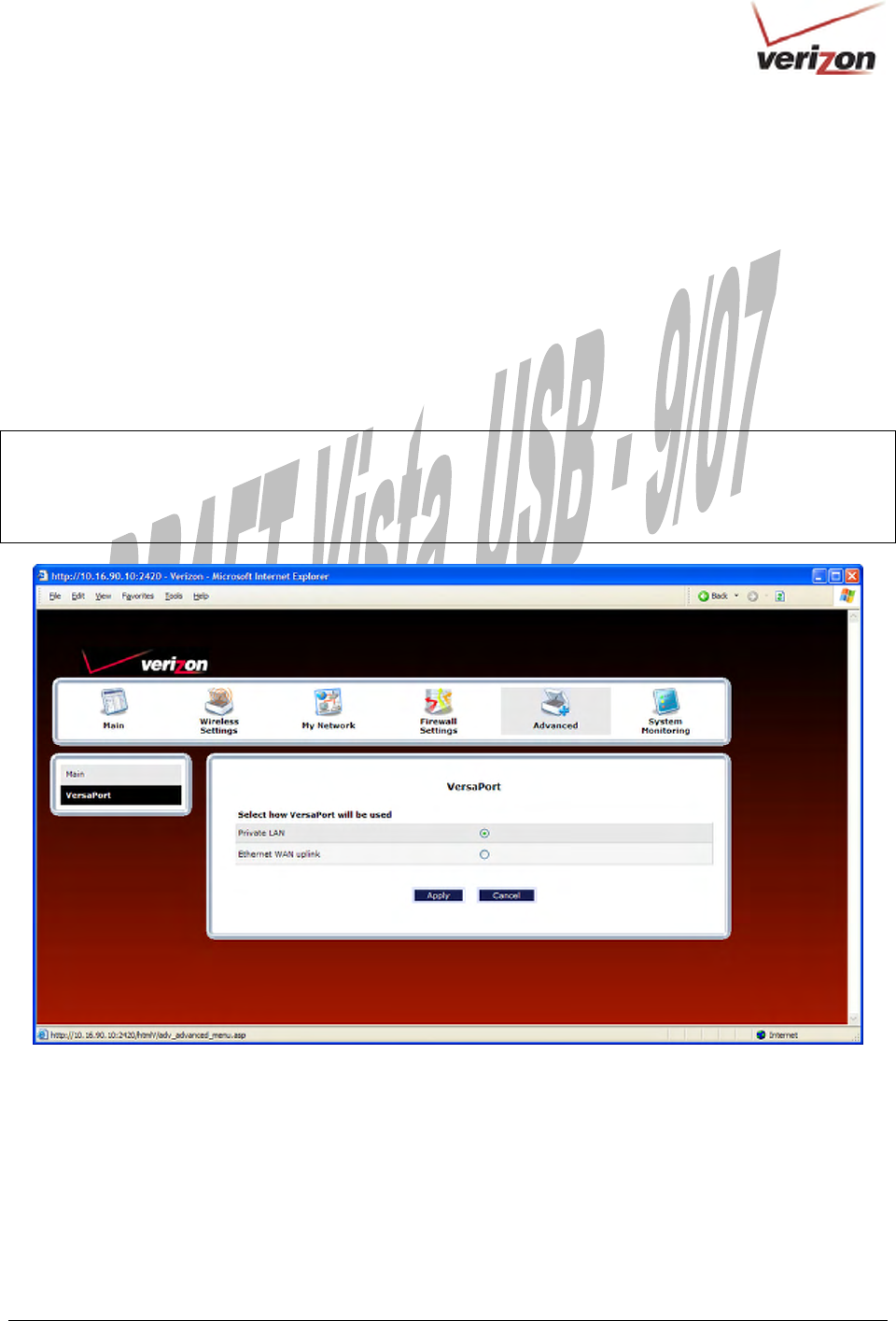
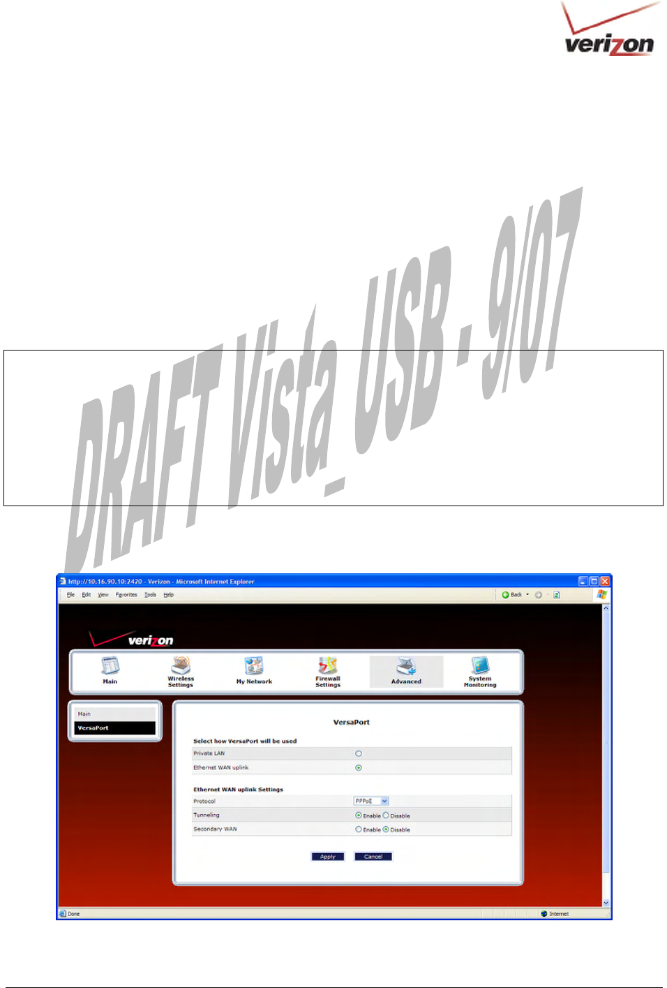
14.2.3 Configuring VersaPort (Ethernet WAN Uplink)
If you clicked the VersaPort link in the Network Connections screen, the following screen will appear. This screen
allows you to select how the UPLINK/E1 port on the rear of the Router will be used.
Select one of the following options:
• Private LAN: This mode allows you to use the Router’s DSL port for WAN access (the Router’s DSL
functionality is enabled).
• Ethernet WAN Uplink. This mode allows you to use the Router as an Ethernet Gateway (for example,
connecting to a cable modem or to another ADSL device that provides WAN access). In WAN Uplink
mode, the Router’s DSL functionality is disabled.
NOTE: The menu options displayed will vary according to the configuration you have chosen to use, LAN Ethernet
port or WAN Uplink port. If you are using WAN Uplink port, some menu options will not be available. However,
all menu options will be available when the Router is enabled for LAN Ethernet port. Instructions on enabling and
disabling LAN Ethernet port and WAN Uplink port are explained in the following sections. This document was
created with the Router configured for LAN Ethernet port.
030-300536 Rev. A 90 August 2007
User GuideVersaLink Wireless Gatewa
y
(
Model 7500
)
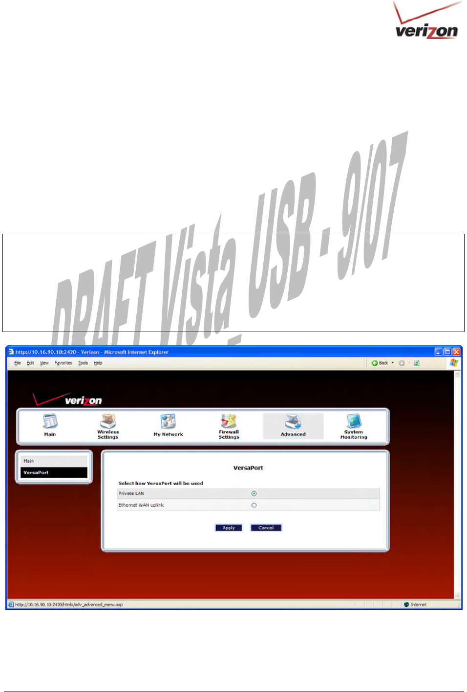
14.2.3.1 Enabling Private LAN—Disabling Ethernet WAN Uplink
If you selected Private LAN in the VersaPort screen, this will enable the Router’s DSL transceiver, and the Router
will use its DSL port as the WAN interface. This configuration will disable the WAN Uplink port (UPLINK/E1 on
the rear of the Router).
• When Private LAN is selected, the DSL port on the rear of the Router is enabled and is the WAN interface
to the Internet.
• When Ethernet WAN Uplink is selected, the UPLINK/E1 port on the rear of the Router is enabled and is
the WAN uplink to another ADSL device through which you will make your Internet connection.
Remember, you must click Apply to allow the settings to take effect in the Router.
NOTE:
1. When using the optional UPLINK/E1 port, Ethernet LAN connection is limited to E2, E3, and E4.
The WAN Uplink feature is optional and, if it is disabled, the Router will use DSL only as the WAN interface.
2. Some menu options are unavailable when the Router is configured for WAN Uplink port. However, all of the
Router’s menu options are displayed when the Router is configured for LAN Ethernet port.
3. The Router’s factory default setting is Private LAN.
4. If WAN Uplink is not enabled in the .ini file, the Router will use DSL only as the WAN interface.
030-300536 Rev. A 91 August 2007
User GuideVersaLink Wireless Gatewa
y
(
Model 7500
)
14.2.3.2 Enabling Ethernet WAN Uplink—Disabling Private LAN
If you selected Ethernet WAN Uplink in the VersaPort screen, this will disable the Router’s DSL transceiver and
the DSL port. This configuration allows the port labeled UPLINK/E1 on the rear of the Router to become the WAN
interface port. Then, you can use UPLINK/E1 to uplink to another ADSL device, through which you can connect to
the Internet.
• When Private LAN is selected, the DSL port on the rear of the Router is enabled and is the WAN interface
to the Internet.
• When Ethernet WAN Uplink is selected, the UPLINK/E1 port on the rear of the Router is enabled and is
the WAN uplink to another ADSL device through which you will make your Internet connection.
Remember, you must click Apply to allow the settings to take effect in the Router.
NOTE:
1. When using the optional UPLINK/E1 port, Ethernet LAN connection is limited to E2, E3, and E4.
The UPLINK feature is optional and, if it is disabled, the Router will use DSL only as the WAN interface.
2. All of the Router’s menu options are displayed when the Router is configured for LAN Ethernet port. However,
some menu options are unavailable when the Router is configured for WAN Uplink port. The sections explained
throughout this document will indicate when a menu item is unavailable.
3. The Router’s factory default setting is Private LAN.
4. If UPLINK is not enabled in the .ini file, the Router will use DSL only.
If you selected Ethernet WAN Uplink, the following screen will be displayed. Proceed to the next section for
instructions on editing the Ethernet WAN Uplink settings.
030-300536 Rev. A 92 August 2007
User GuideVersaLink Wireless Gatewa
y
(
Model 7500
)
14.2.3.3 Editing the VC Protocol Settings for Ethernet WAN Uplink
NOTE: The instructions in this section refer to the Router configured for Ethernet WAN Uplink mode. Be sure that
you have selected Ethernet WAN Uplink in the VersaPort screen.
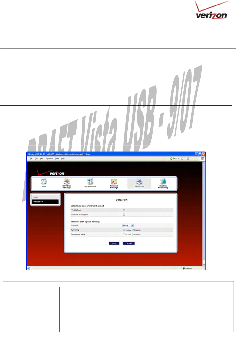
14.2.3.3.1 Configuring the WAN Uplink Protocol Settings for PPPoE
After you have selected Ethernet WAN Uplink, in the preceding steps, select the desired protocol from the
Protocol drop-down menu. If you select PPPoE, the following screen will appear. Select the desired options, and
then click Apply to save the settings.
NOTE:
1. If you experience any problems, reset the Router by pressing the reset button on the rear of the Router. Or follow
the instructions in section 16.2, “Restore Defaults,” to restore the Router to factory default settings. The actual
information displayed in this screen may vary, depending on network connection established.
2. PPPoE is the factory default setting for Ethernet WAN Uplink.
Uplink Settings for Ethernet WAN Uplink (PPPoE protocol)
Tunneling Factory Default = Enable
If Enabled, this option allows PPP traffic to be bridged to the WAN. This feature
allows you to use a PPPoE shim on the host computer to connect to the Internet
Service Provider, by bypassing the Router’s capability to do this. Factory default is
“Enable.”
Secondary WAN Factory Default = Disable
The secondary WAN interface is used for multicast traffic. This feature applies only
when you are using PPPoE as the Primary WAN protocol.
030-300536 Rev. A 93 August 2007
User GuideVersaLink Wireless Gatewa
y
(
Model 7500
)
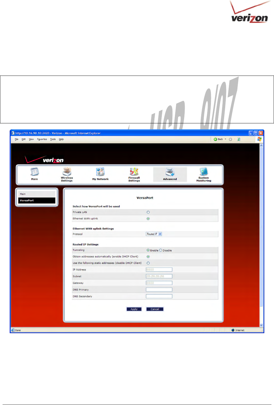
14.2.3.3.2 Configuring the Ethernet WAN Uplink Protocol Settings for Routed IP
If you select Routed IP from the Protocol drop-down menu, the following screen will appear. Enter the desired
options, and then click Apply to save the settings.
NOTE:
1. If you experience any problems, reset the Router by pressing the reset button on the rear of the Router. Or follow
the instructions in section 16.2, “Restore Defaults,” to restore the Router to factory default settings. The actual
information displayed in this screen may vary, depending on network connection established.
2. PPPoE is the factory default setting for Ethernet WAN Uplink.

030-300536 Rev. A 94 August 2007
User GuideVersaLink Wireless Gatewa
y
(
Model 7500
)
Uplink Settings for Ethernet WAN Uplink (Routed IP protocol)
Tunneling Factory Default = Enable
If Enabled, this option allows PPP traffic to be bridged to the WAN. This feature
allows you to use a PPPoE shim on the host computer to connect to the Internet
Service Provider, by bypassing the Router’s capability to do this.
DHCP Client Selecting a option allows you to either Enable or Disable the DHCP Client.
Click the top option labeled (enable DHCP Client) to allow the Router to obtain an IP
address automatically from your service provider.
Click the bottom option labeled (disable DHCP Client) to allow the Router to accept
static IP address information. Then, manually enter the IP values into the fields. Obtain
these values from Verizon.
IP Address The IP network address that your Router is on.
Subnet The IP subnet address that your Router is on.
Gateway The Router’s IP gateway address.
DNS Primary Provided by Verizon.
DNS Secondary Provided by Verizon.
Note: The values for the IP Address, Gateway, DNS Primary, and DNS Secondary are all “Override of the value
obtained from the PPP connection,” They default to “0.0.0.0,” in which case the override is ignored. It is
recommended that you do not change the values unless Verizon instructs you to do so.
030-300536 Rev. A 95 August 2007
User GuideVersaLink Wireless Gatewa
y
(
Model 7500
)
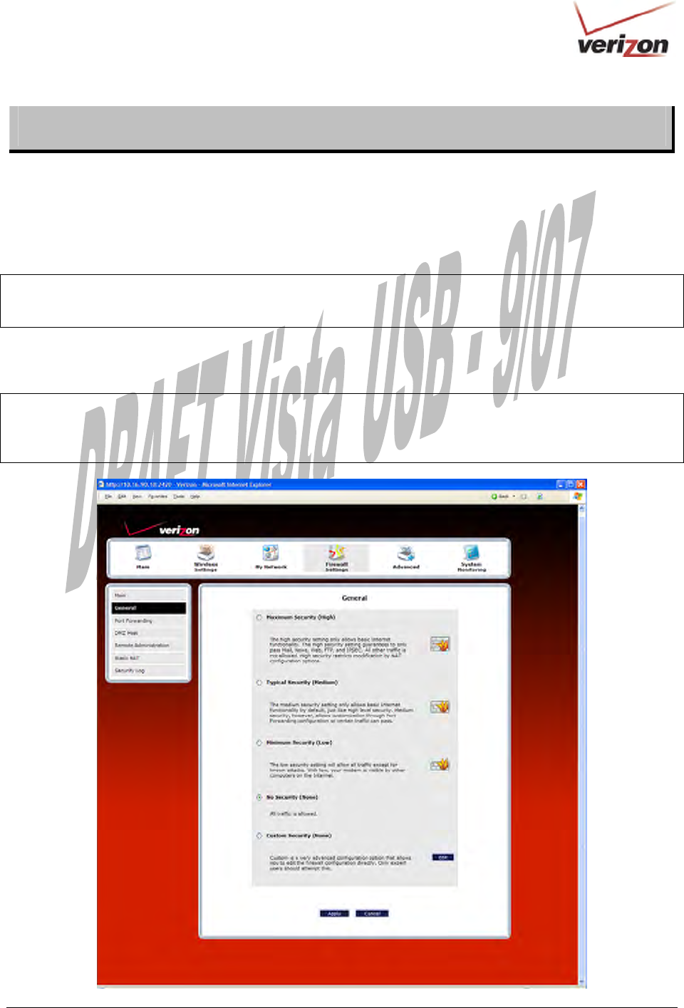
15. FIREWALL SETTINGS
15.1 General Firewall Security Settings
This section explains how to configure your Router’s firewall security features. The Router’s firewall security
settings allow you reduce the risk of unauthorized access to your network by prohibiting certain types of inbound
and outbound network traffic and by allowing you to configure specific firewall rules.
IMPORTANT: If you need help, click Main in the top navigational menu to go to the home page. In the Quick
Links section of the home page, click Verizon Help. Clicking this link takes you to Verizon’s OnLine Help site,
where you can access additional information about your DSL Router.
To change your firewall security level, click the option next to the desired security setting. Next, click Apply to
allow the changes to take effect.
IMPORTANT: It is recommended that you do not change the settings in this User Defined Firewall Rules screen.
If you need to reset your Router to factory default settings, push the reset button on the rear of the Router. Or follow
the instructions in section 16.2, “Restore Defaults,” to restore the Router to factory default settings.
The factory default security level for your Router is No Security (None).
030-300536 Rev. A 96 August 2007
User GuideVersaLink Wireless Gatewa
y
(
Model 7500
)
General Firewall Settings
Maximum Security
(High)
High security level only allows basic Internet functionality. Only Mail, News, Web,
FTP, and IPSEC are allowed. All other traffic is prohibited.
Typical Security
(Medium)
Like High security, Medium security only allows basic Internet functionality by
default. However, Medium security allows customization through NAT configuration
so that you can enable the traffic that you want to pass.
Minimum Security
(Low)
Low security setting will allow all traffic except for known attacks. With Low
security, your Router is visible to other computers on the Internet.
No Security
(None)
Factory Default = No Security (None)
The Firewall is disabled. (All traffic is passed)
Custom Security
(Custom)
Custom is a security option that allows you to edit the firewall configuration directly.
Note: Only the most advanced users should try this.
15.2 Editing Firewall Security Rules
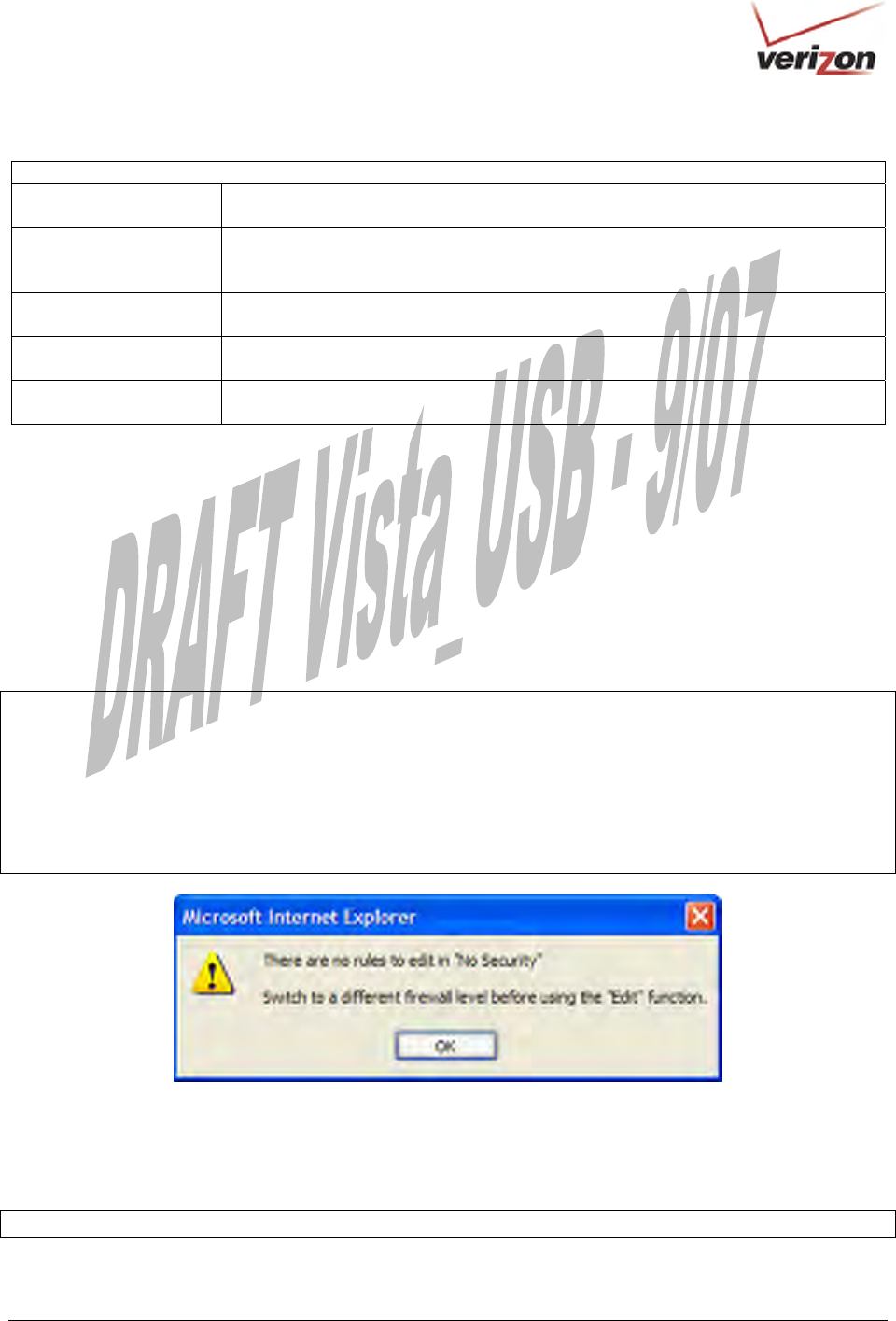
To edit the firewall security rules and customize them to your preference, in the General screen, click Edit. If no
security rules have been previously configured, the following pop-up screen will appear. Click OK in the pop-up
screen. At the General screen, select the security option that want to edit, and then click Apply.
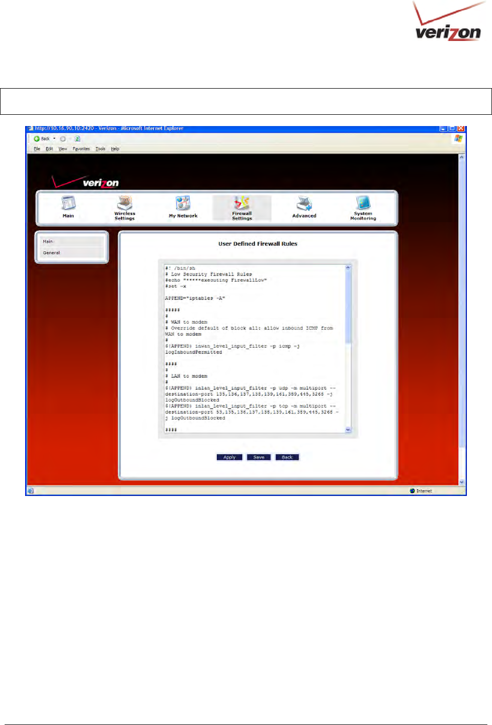
Next, select the Custom Security (None) option in the General screen, and then click Apply. Click Edit to go to
the User Defined Firewall Rules screen and edit the security rules for the security option you selected (High,
Medium, Low, None) in the General screen.
IMPORTANT:
1. Custom Security is a very advanced configuration option that allows you to edit the firewall configuration
directly. Only expert users should attempt this. It is recommended that you do not change the settings in this
screen. If you need to reset your Router to factory default settings, push the reset button on the rear of the Router.
Or follow the instructions in section 16.2, “Restore Defaults,” to restore the Router to default settings.
2. If you need help, click Main in the top navigational menu to go to the home page, and then click Verizon Help to
access Verizon’s Online Help Web site for your DSL Router.
The User Defined Firewall Rules screen allows you to configure the security parameters on your Inbound and
Outbound traffic. Inbound rules will restrict inbound traffic from the WAN to the LAN. Outbound rules will restrict
outbound traffic from the LAN to WAN. Enter the desired parameters, click Save, and then click Apply to allow the
settings to take effect in your Router.
NOTE: Clicking Save allows the firewall rules to be saved to flash (a temporary storage area in your Router).
030-300536 Rev. A 97 August 2007
User GuideVersaLink Wireless Gatewa
y
(
Model 7500
)
NOTE: The information displayed in this screen may differ from your actual screen, depending on the level of
security you have selected.
030-300536 Rev. A 98 August 2007
User GuideVersaLink Wireless Gatewa
y
(
Model 7500
)
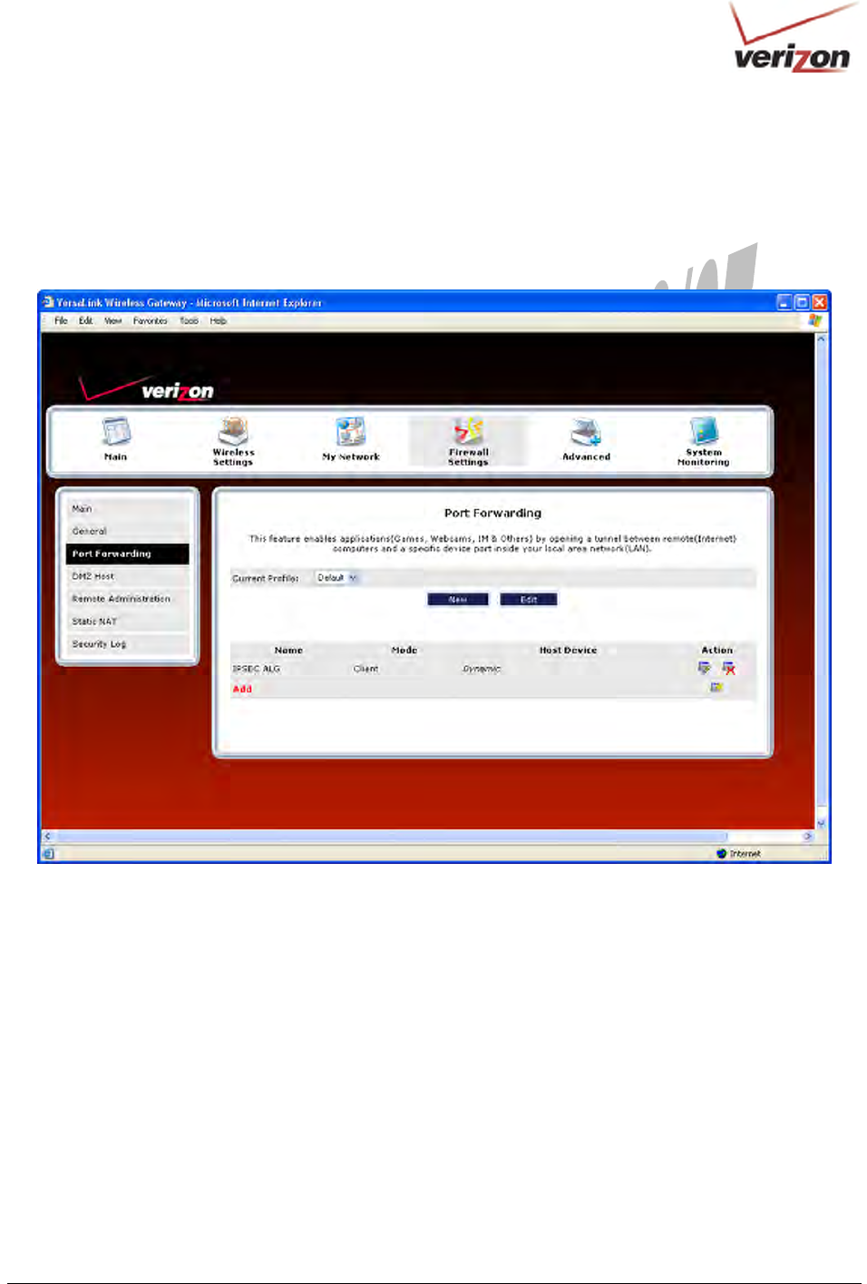
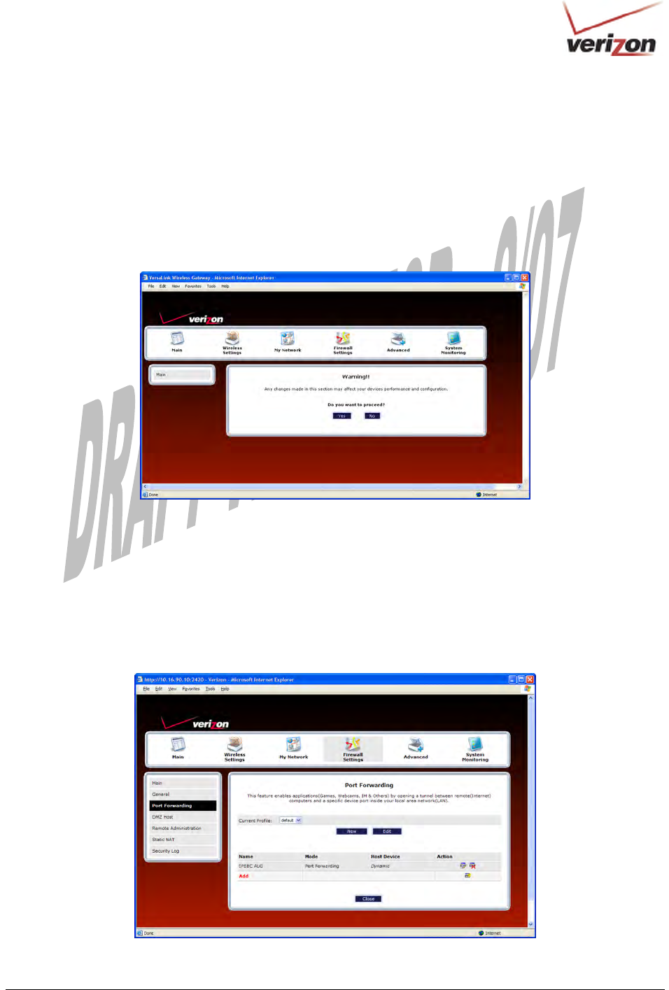
15.3 Port Forwarding
To access the Port Forwarding screen, from the top navigational menu, select Firewall Settings. Then select Port
Forwarding from the menu options at the left of the screen. A warning screen will display the following message:
Any changes made in this section may affect your device’s performance and configuration.
Do you want to proceed?
Click Yes to proceed.
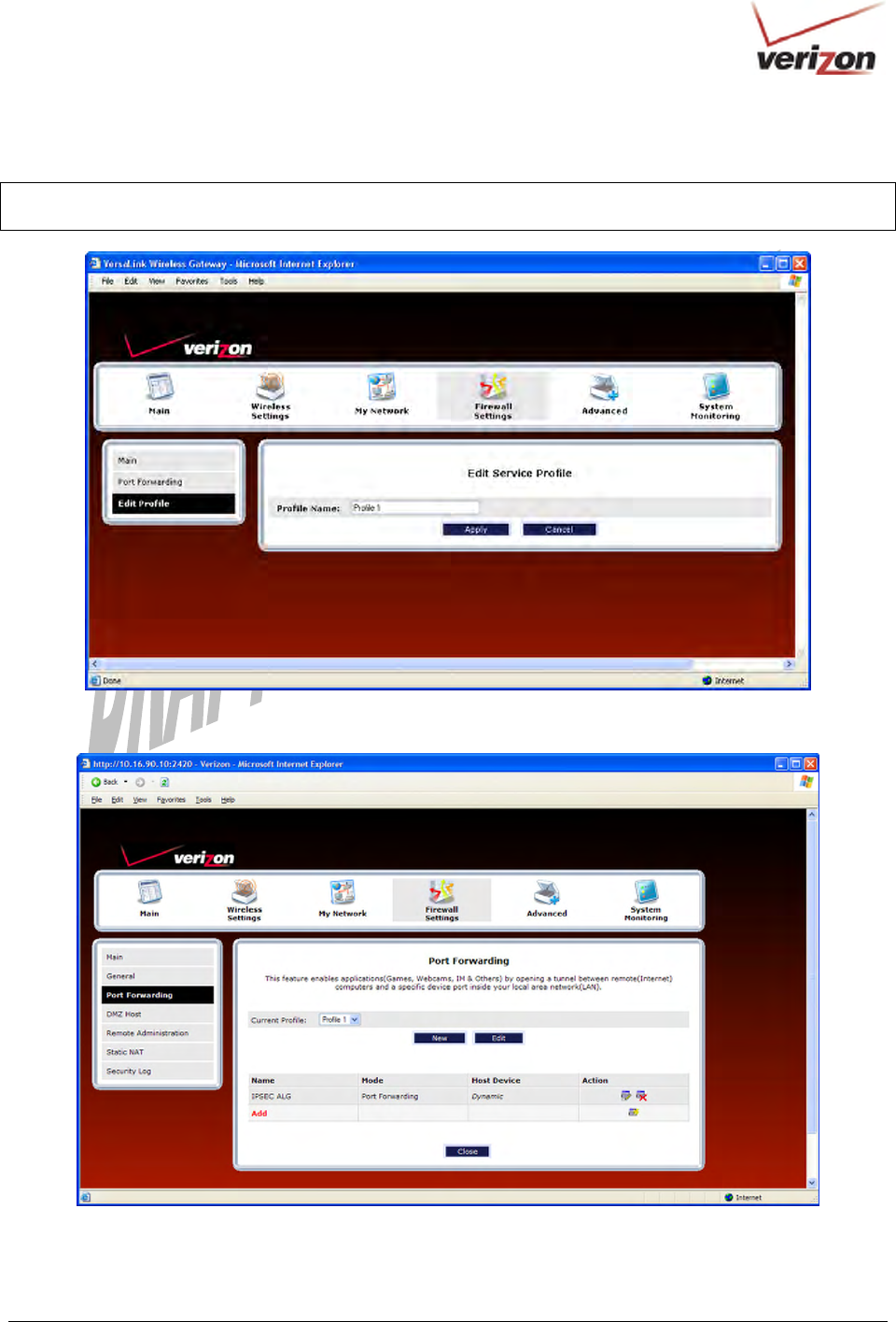
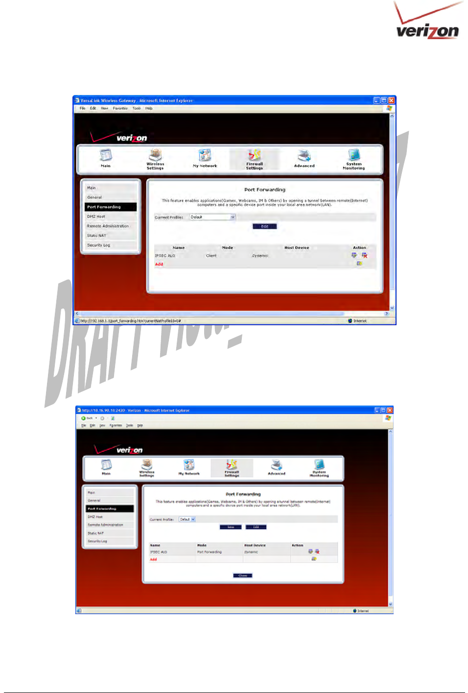
If you clicked Yes, in the preceding warning screen, the following Port Forwarding screen will be displayed.
This feature enables applications (Games, Webcams, IM & Others) by opening a tunnel between remote (Internet)
computers and a specific device port inside your local area network (LAN).
The Port Forwarding screen allows you to do the following:
• Edit connection profiles, create new connection profiles
• Configure port forwarding services: predefined, customized, and port forwarding/port triggering services
030-300536 Rev. A 99 August 2007
User GuideVersaLink Wireless Gatewa
y
(
Model 7500
)
15.3.1 Editing a Profile Name
Port Forwarding services can be added to connection profiles. To edit an existing profile name, and then later add
port forwarding services to the profile, follow the instructions in this section.
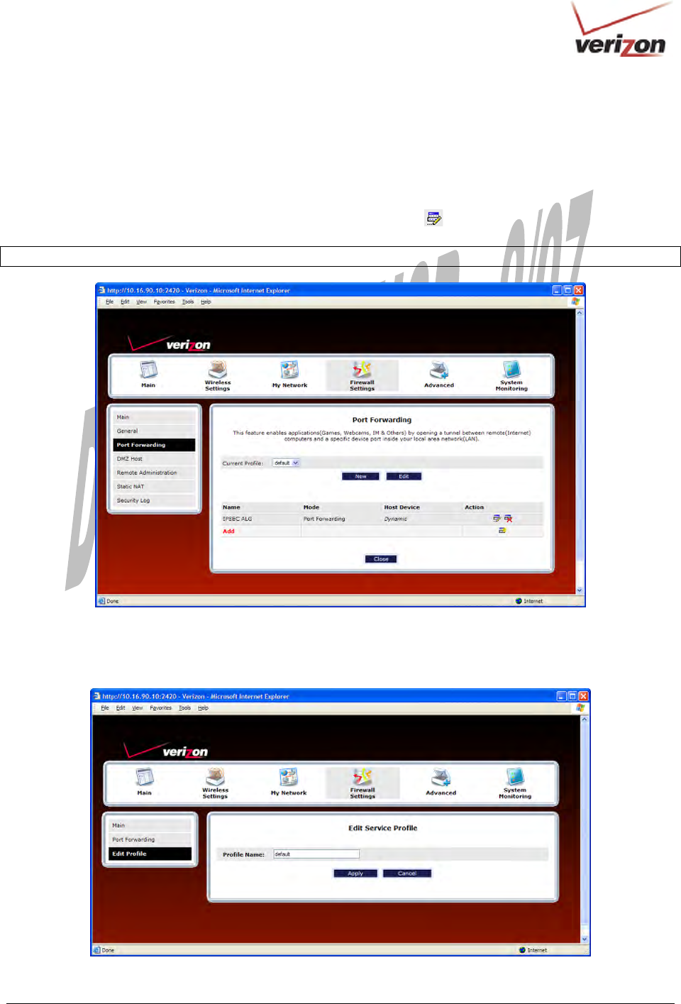
To edit a connection profile name, in the Port Forwarding screen, click the Current Profile drop-down menu, and
then select the name of the profile that you want to edit. Next, click Edit .
NOTE: If you have not previously configured a profile, the “Default” profile will be displayed.
If you have selected a profile and clicked Edit, the following screen will appear. In the following example,
“Default” has been selected from the Current Profile drop-down menu displayed in the preceding screen. This is
the profile name that will be edited.
030-300536 Rev. A 100 August 2007
User GuideVersaLink Wireless Gatewa
y
(
Model 7500
)
Type the name of your choice in the field provided. Then, click Apply to allow the change to take effect.
NOTE: If you reset your Router to factory default settings, the default profile “Default” will be displayed, and any
previously configured settings will be lost.
The name you entered should now be displayed in the Current Profile drop-down menu.
030-300536 Rev. A 101 August 2007
User GuideVersaLink Wireless Gatewa
y
(
Model 7500
)
15.3.2 Creating a New Connection Profile
If you desire to create a new profile, and then later add port forwarding services to the new profile, follow the
instructions in this section.
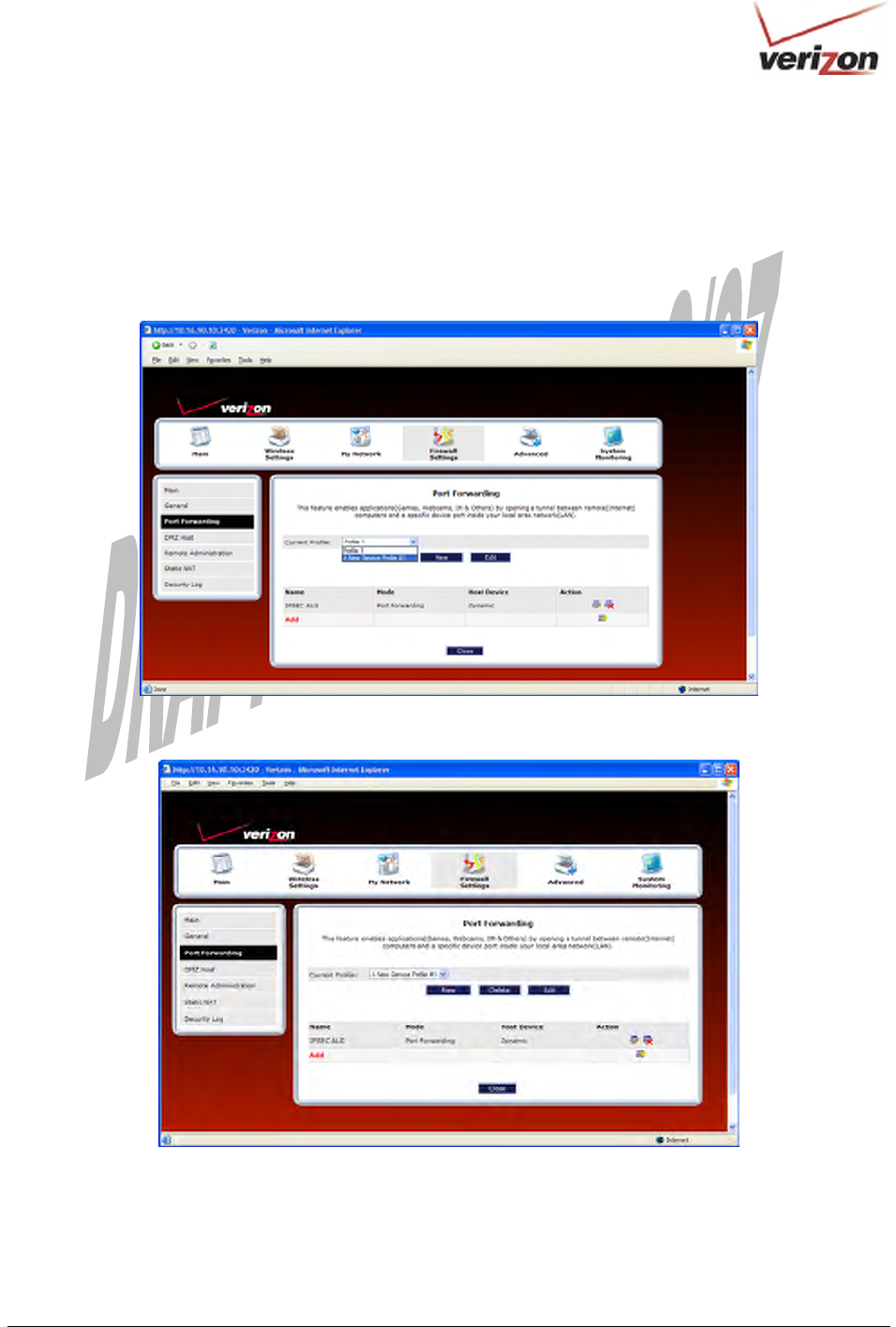
To create a new connection profile, in the Port Forwarding screen, click New. Then, from the Current Profile
drop-down menu, select A New Service Profile #1.
Next, click the Edit button to edit the profile.
030-300536 Rev. A 102 August 2007
User GuideVersaLink Wireless Gatewa
y
(
Model 7500
)
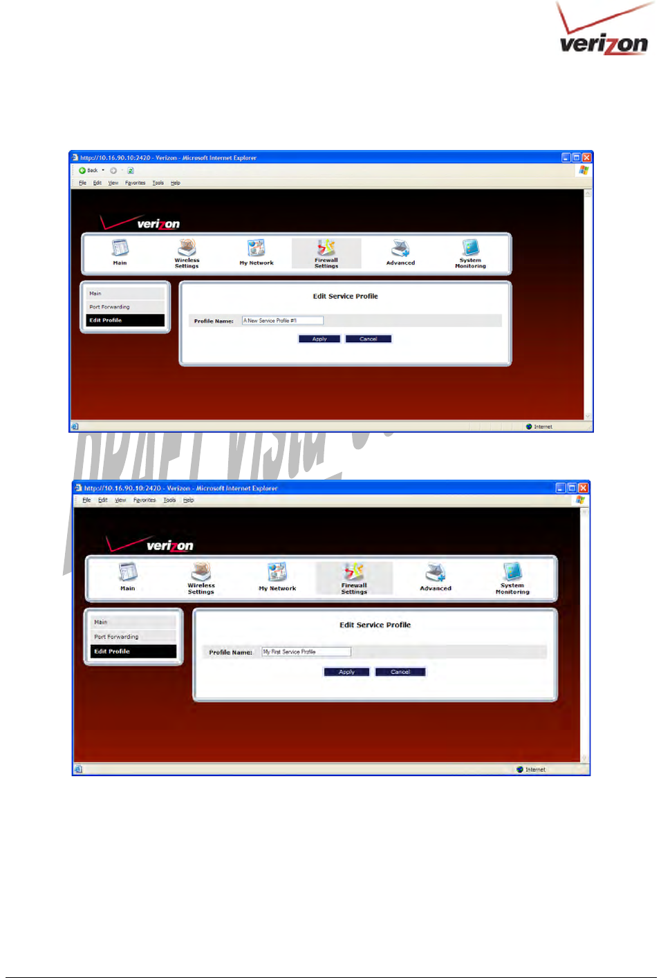
If you clicked the Edit button, the following screen will appear. Type the profile name of your choice in the field,
and then click Apply to allow the change to take effect.
For example, “My First Service Profile” is the name that has been entered in the Profile Name field. Click Apply.
030-300536 Rev. A 103 August 2007
User GuideVersaLink Wireless Gatewa
y
(
Model 7500
)
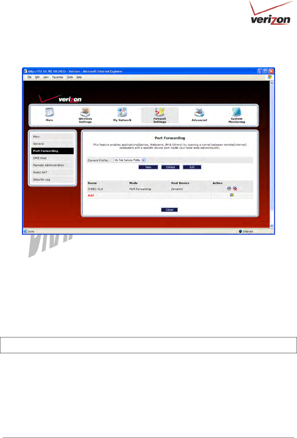
If you clicked Apply, the following screen will be displayed. The Current Profile field now displays the profile
name that you entered.
15.3.3 Configuring Port Forwarding Services
Port Forwarding Services contain specific service settings. The service can then be associated with connection
profiles, allowing you to customize profiles for specific users. For example, if you want to attach specific services to
a profile or if you want to set up a different connection setting for a profile. You can create new service profiles and
customize them to your preference.
Your Router contains a list of predefined Port Forwarding services, and you can select any service from this list. By
selecting your specific service and setting up a profile, you will ensure that the appropriate ports on your Router are
open and that the required application traffic can pass through your local area network (LAN). For a list of
supported services, go to section 18, “Port Forwarding Services.”
NOTE: You can create up to four service profiles and attach an unlimited number of services to each profile. The
current profile labeled “Default” is the factory default profile.
030-300536 Rev. A 104 August 2007
User GuideVersaLink Wireless Gatewa
y
(
Model 7500
)
15.3.3.1 Adding Port Forwarding Services to a Profile
To add a predefined service to a profile, in the Port Forwarding screen, click the Current Profile drop-down
menu, and then select the name of the profile to which you want to add services. Next, click Add.
030-300536 Rev. A 105 August 2007
User GuideVersaLink Wireless Gatewa
y
(
Model 7500
)
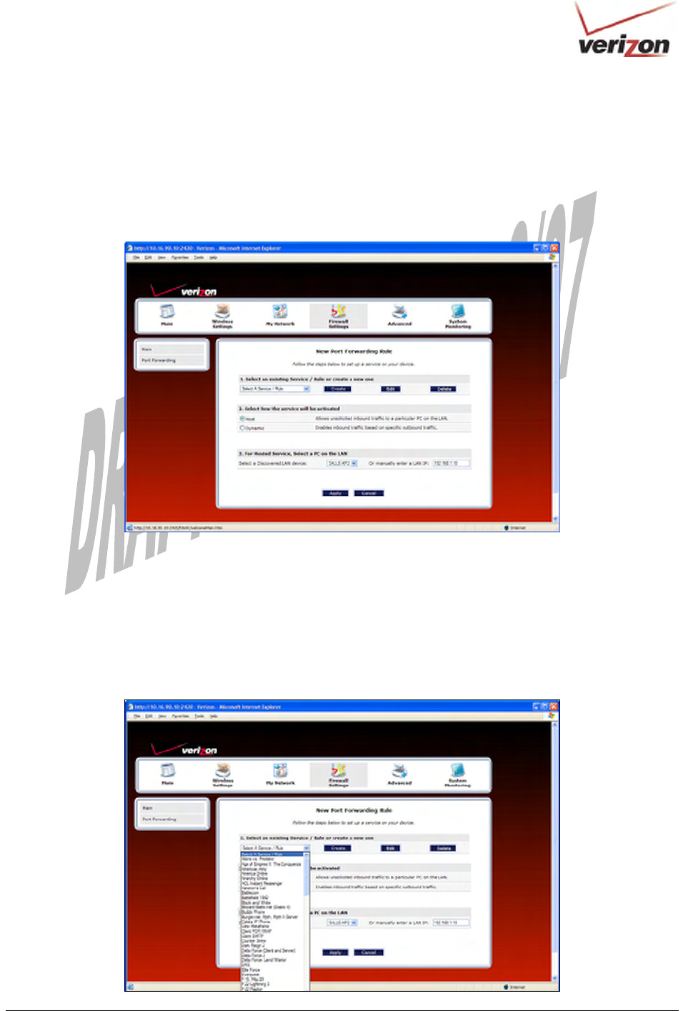
If you clicked Add, the following New Port Forwarding Rule screen will appear. Using this screen, you can do
any of the following:
• Add a predefined service to a profile
• Create a customized service
• Edit an existing service profile
• Delete an existing profile
15.3.3.2 Adding a Predefined Port Forwarding Service to a Profile
To add a predefined port forwarding service to a profile, in the New Port Forwarding Rule screen, perform the
following steps:
1. Select the desired service from the Select a Service drop-down menu. After you have selected a service, it will
appear in the window.
030-300536 Rev. A 106 August 2007
User GuideVersaLink Wireless Gatewa
y
(
Model 7500
)
2. Select the option that describes how you want the service to be activated.
• Host: Allows the unsolicited inbound traffic to a particular PC on the LAN
• Dynamic: Enables inbound traffic based on specific outbound traffic
3. Select the desired IP address from the drop-down menu or manually enter the LAN IP address of the device that
you want to host the service.
4. Click Apply to allow the settings to take effect.
NOTE: If you click Cancel in the New Port Forwarding Rule screen, the service you selected will be displayed;
however, it will not be assigned to a device on the LAN. You must click Apply to allow the settings to take effect.
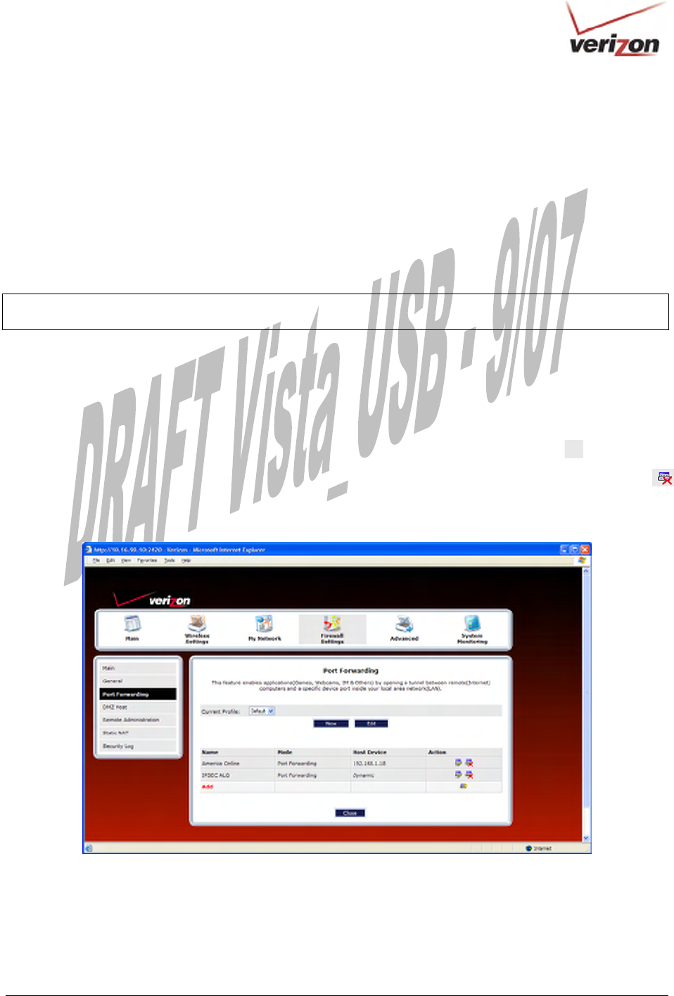
If you clicked Apply, the following screen will be displayed. In this example, the screen shows that service
“America Online” has been added to the “Default” profile.
• To add additional predefined services, in the Port Forwarding screen, first select the desired profile from
the Current Profile drop-down menu. Next, click Add and then repeat the preceding steps 1 through 4.
• To view the details of a service you have added, in the Action field click the details icon .
• To delete a service from your list of active services, at the Port Forwarding screen, click the delete icon
next to the service that you want to delete. The selected service will be deleted from the Router’s list of active
services.
030-300536 Rev. A 107 August 2007
User GuideVersaLink Wireless Gatewa
y
(
Model 7500
)
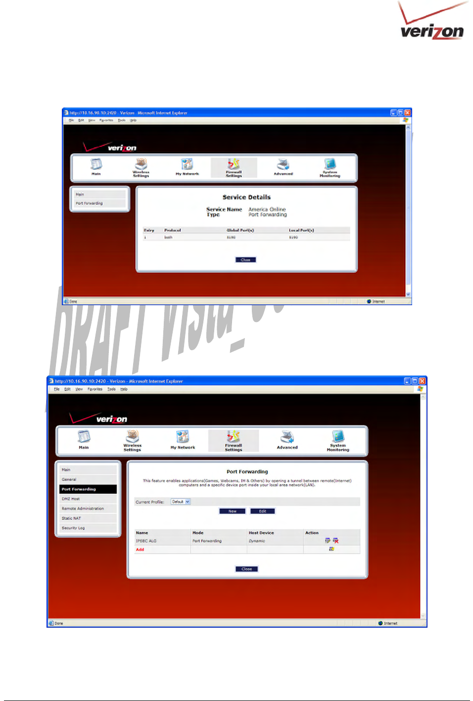
If you clicked the details icon in the preceding screen, the following screen will be displayed. Click Cancel when
you are ready to return to the Port Forwarding screen.
15.3.3.3 Creating a Customized Port Forwarding Service
To create a customized port forwarding service, click Add in the Port Forwarding screen.