Westell A90427XXX-07 Spread Spectrum Transmitter User Manual Part I
Westell Inc Spread Spectrum Transmitter Users Manual Part I
UserManual.wiki
>
Westell
>
A90427XXX-07 User Manual
>
Users Manual Part I
Contents
1.
Users Manual Part I
2.
Users Manual Part II
Users Manual Part I
Navigation menu
Upload a User Manual
Namespaces
Wiki Guide
HTML
PDF
Info
Views
User Manual
Discussion / Help
Navigation


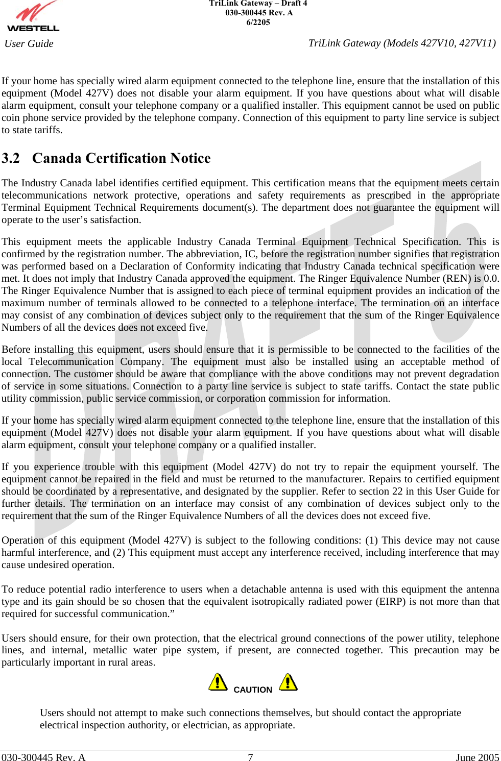
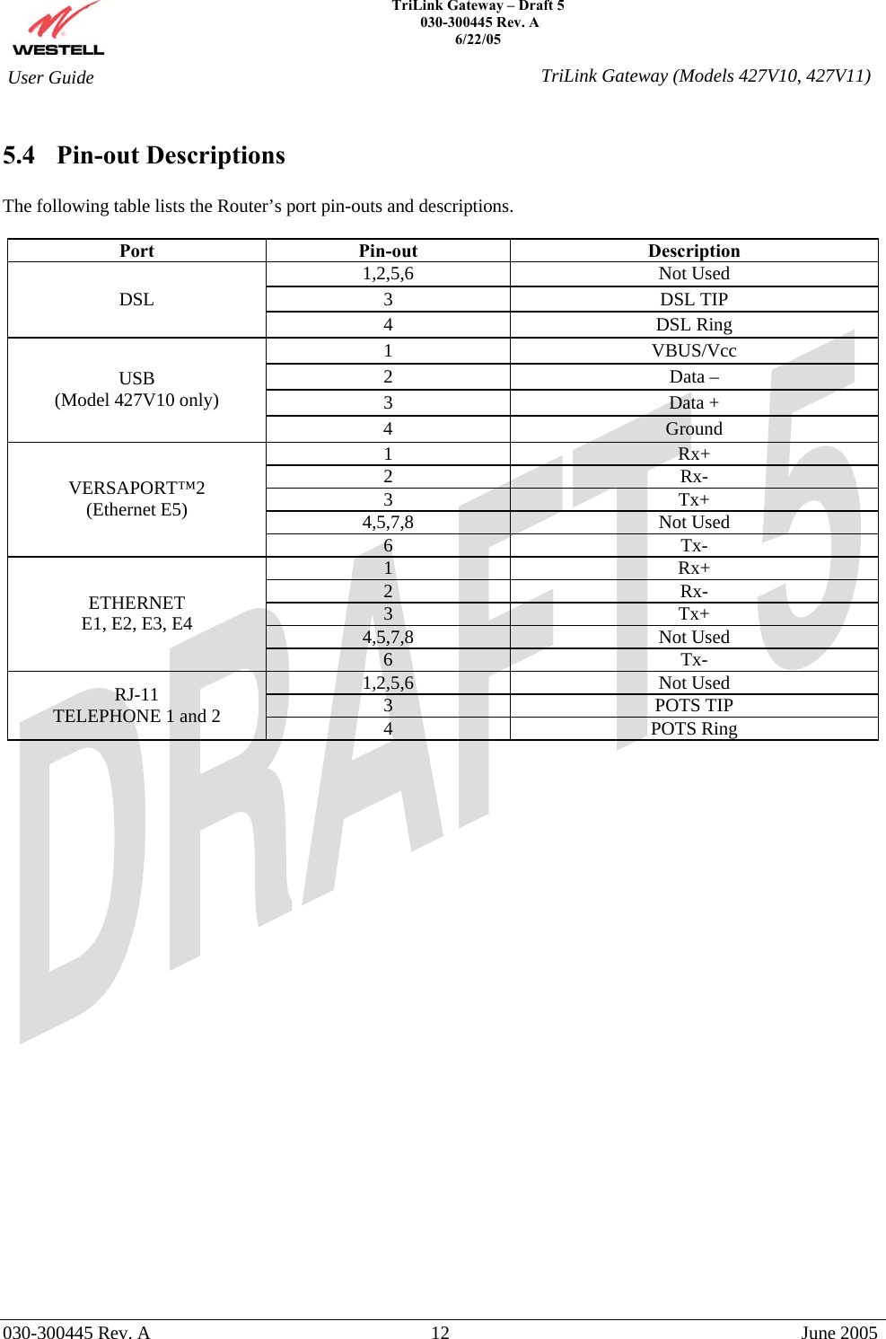

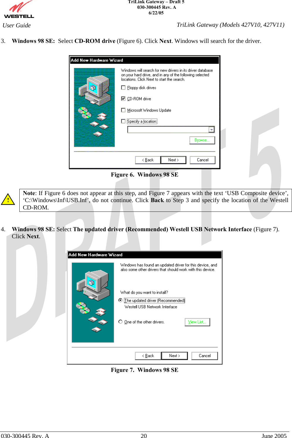

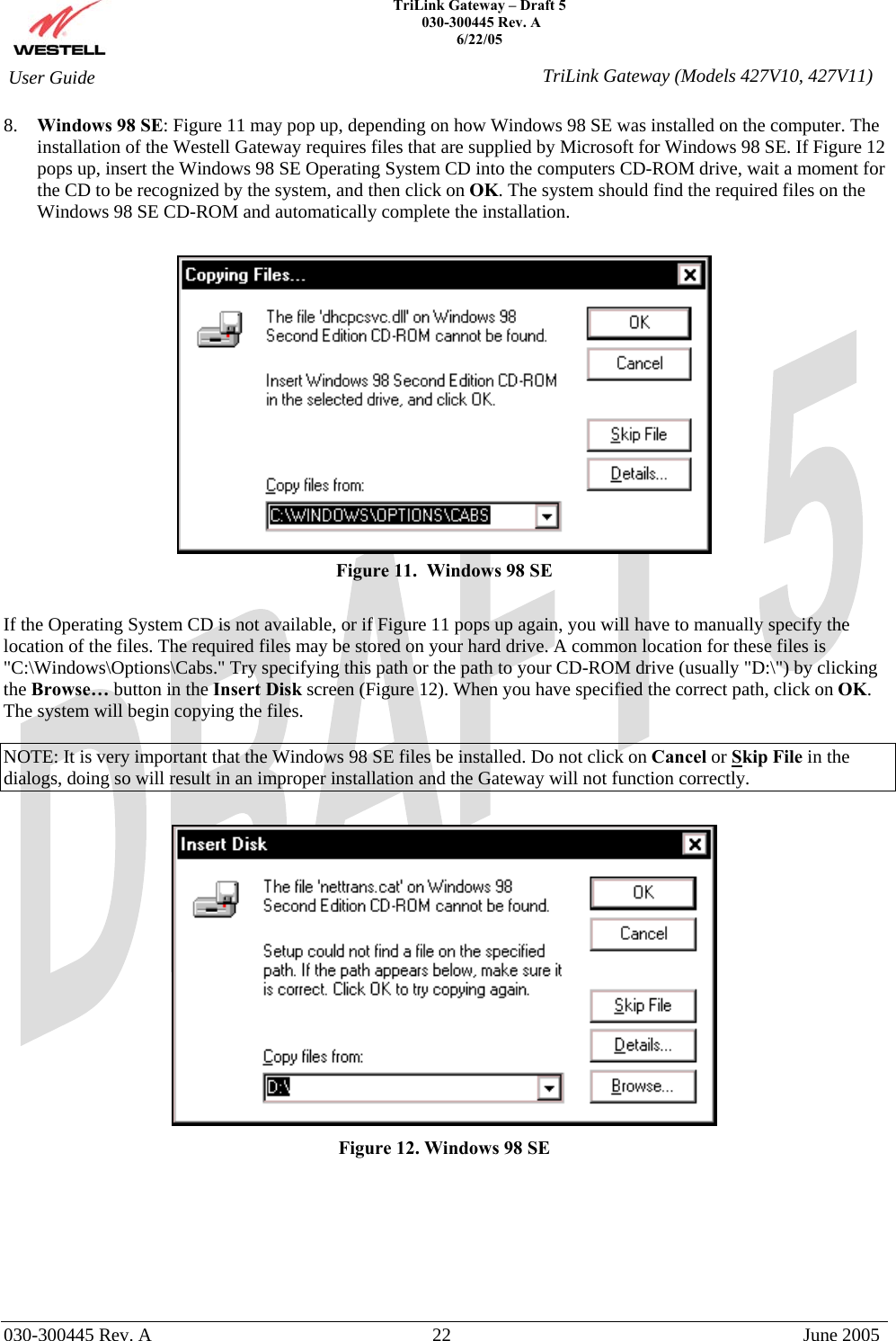
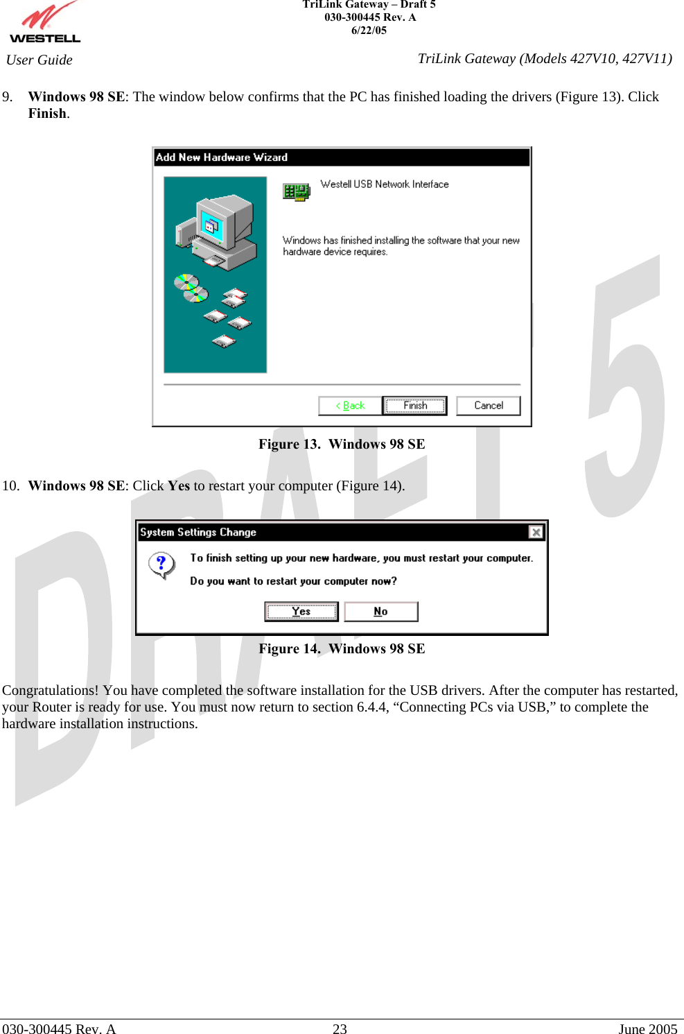
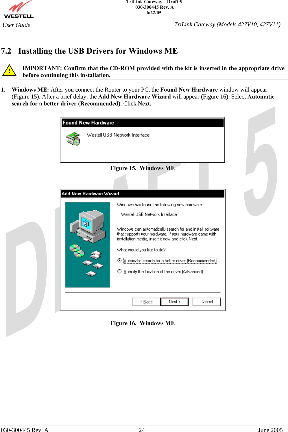
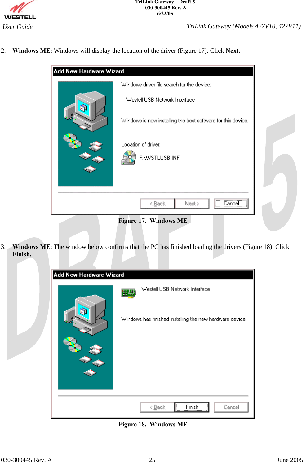
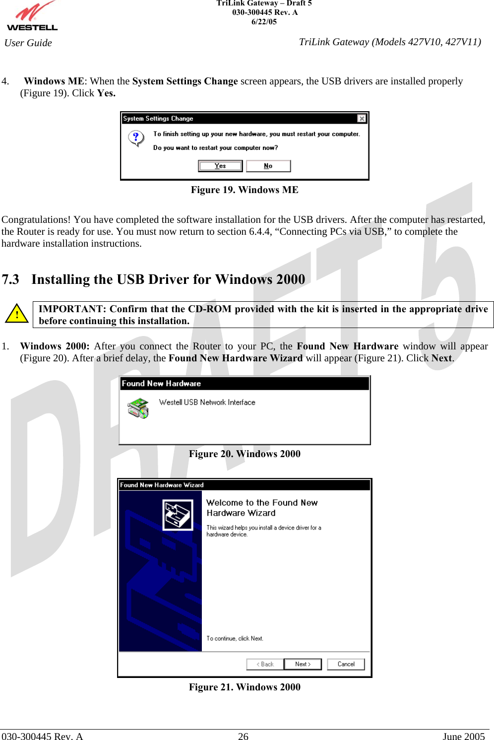
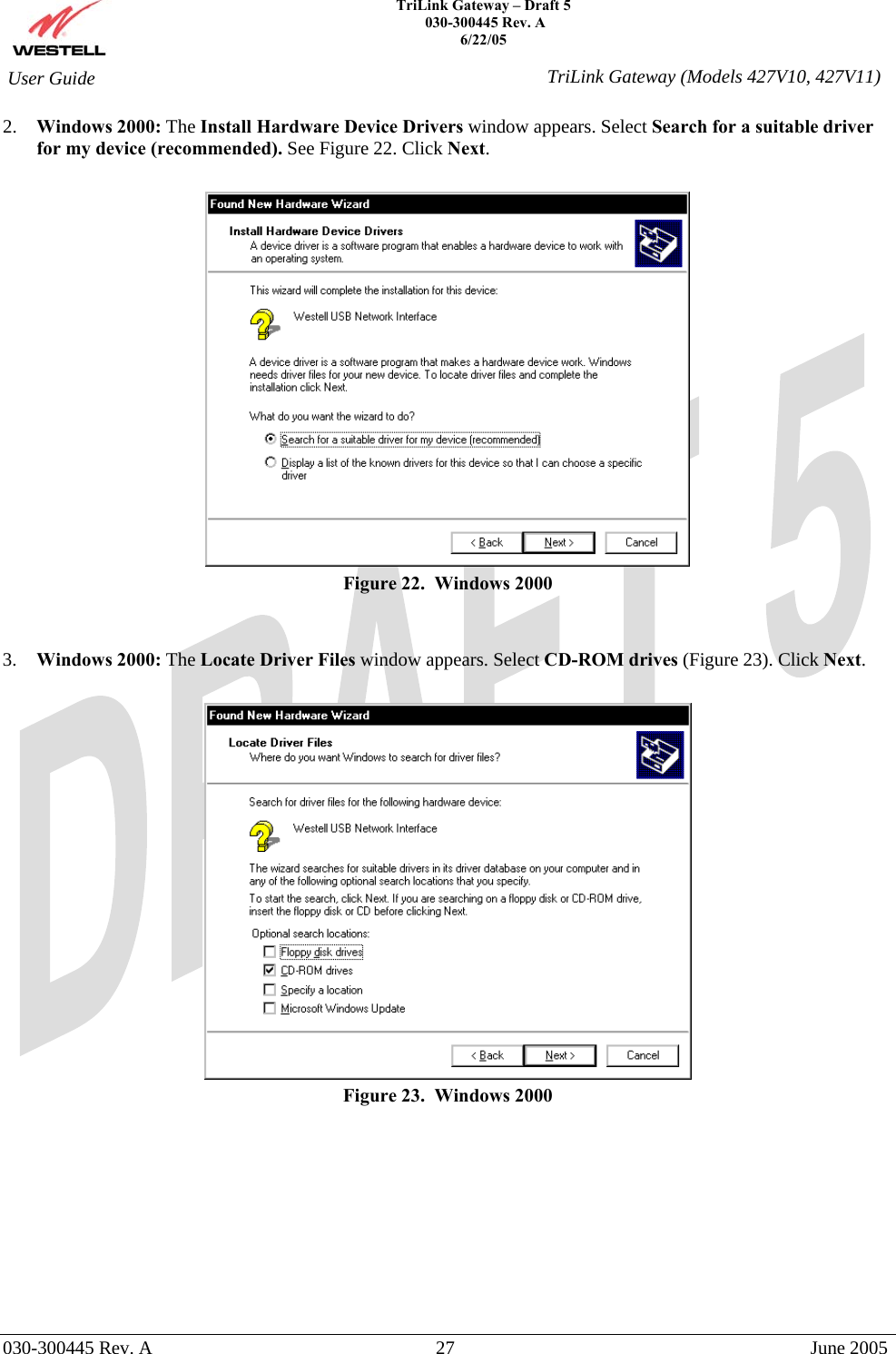
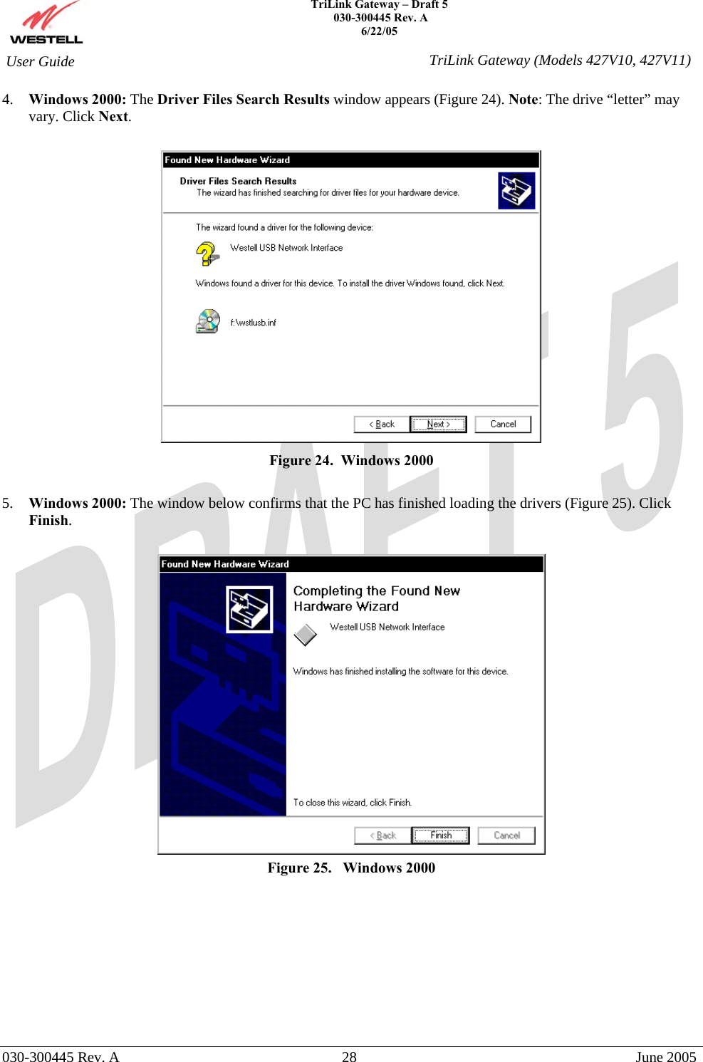
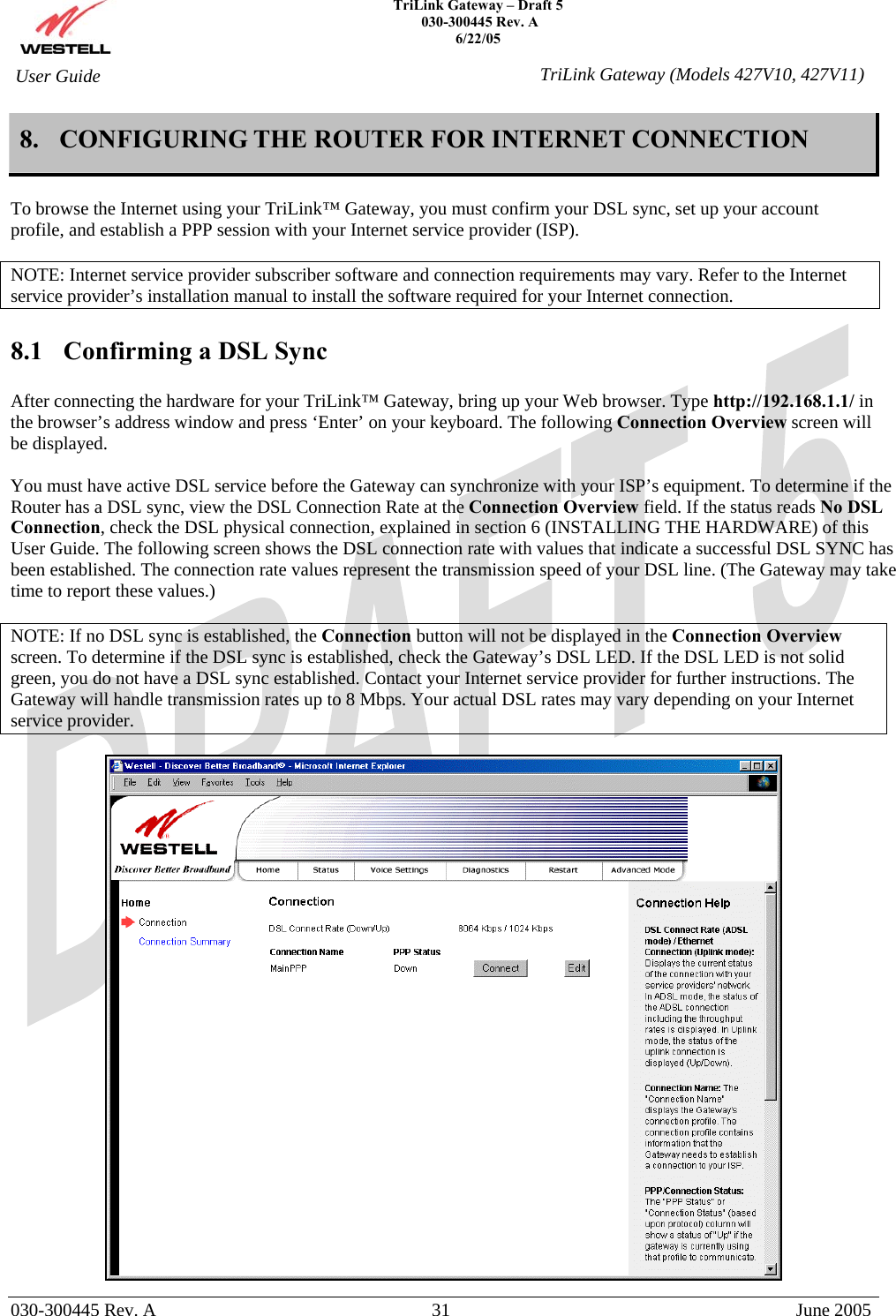
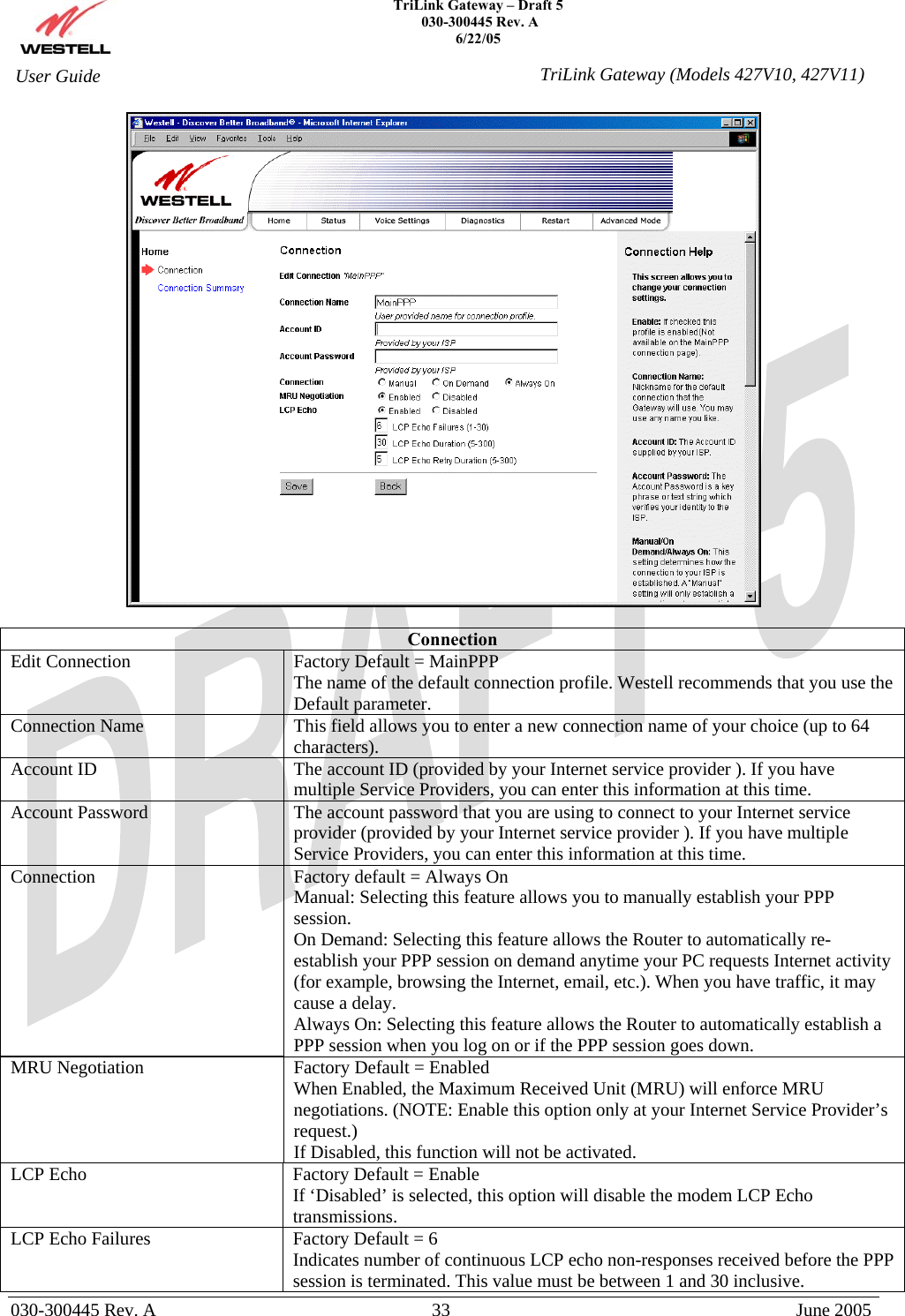
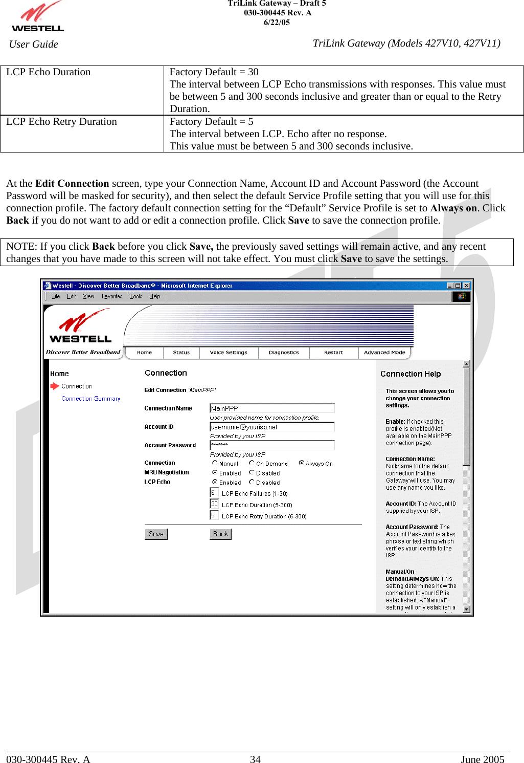
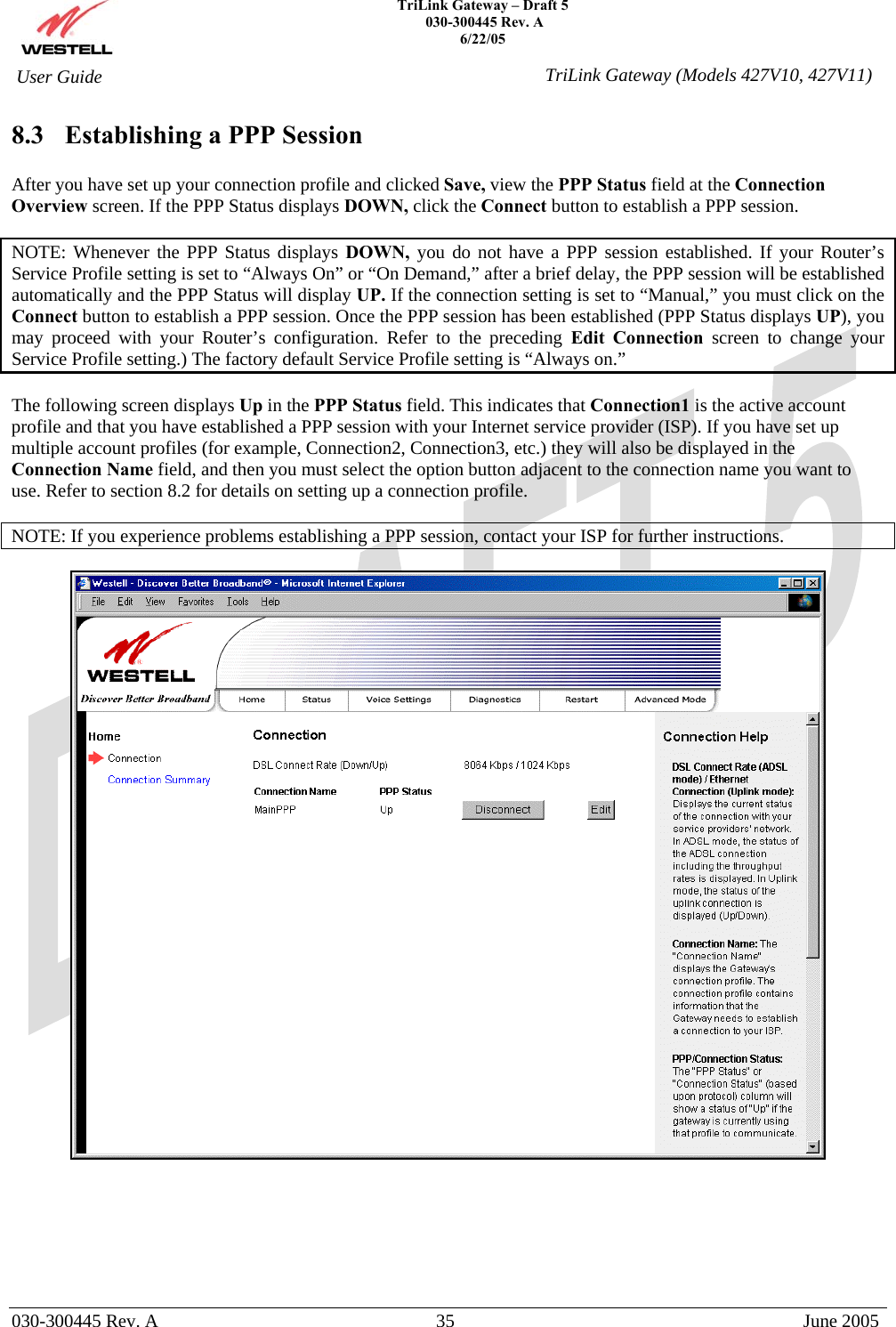
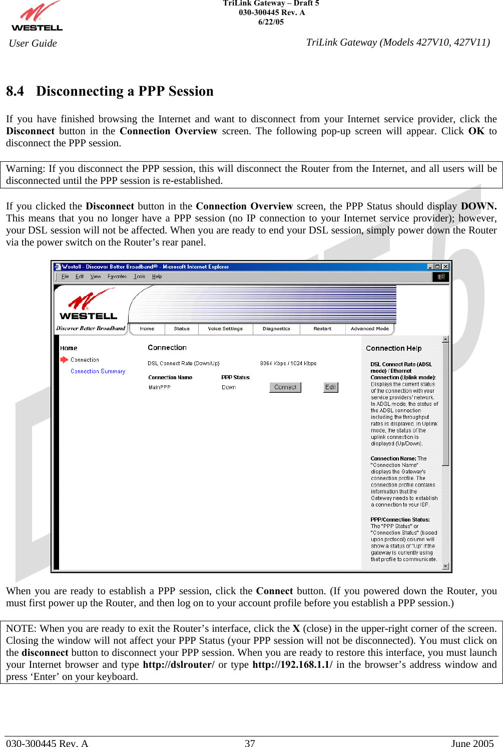
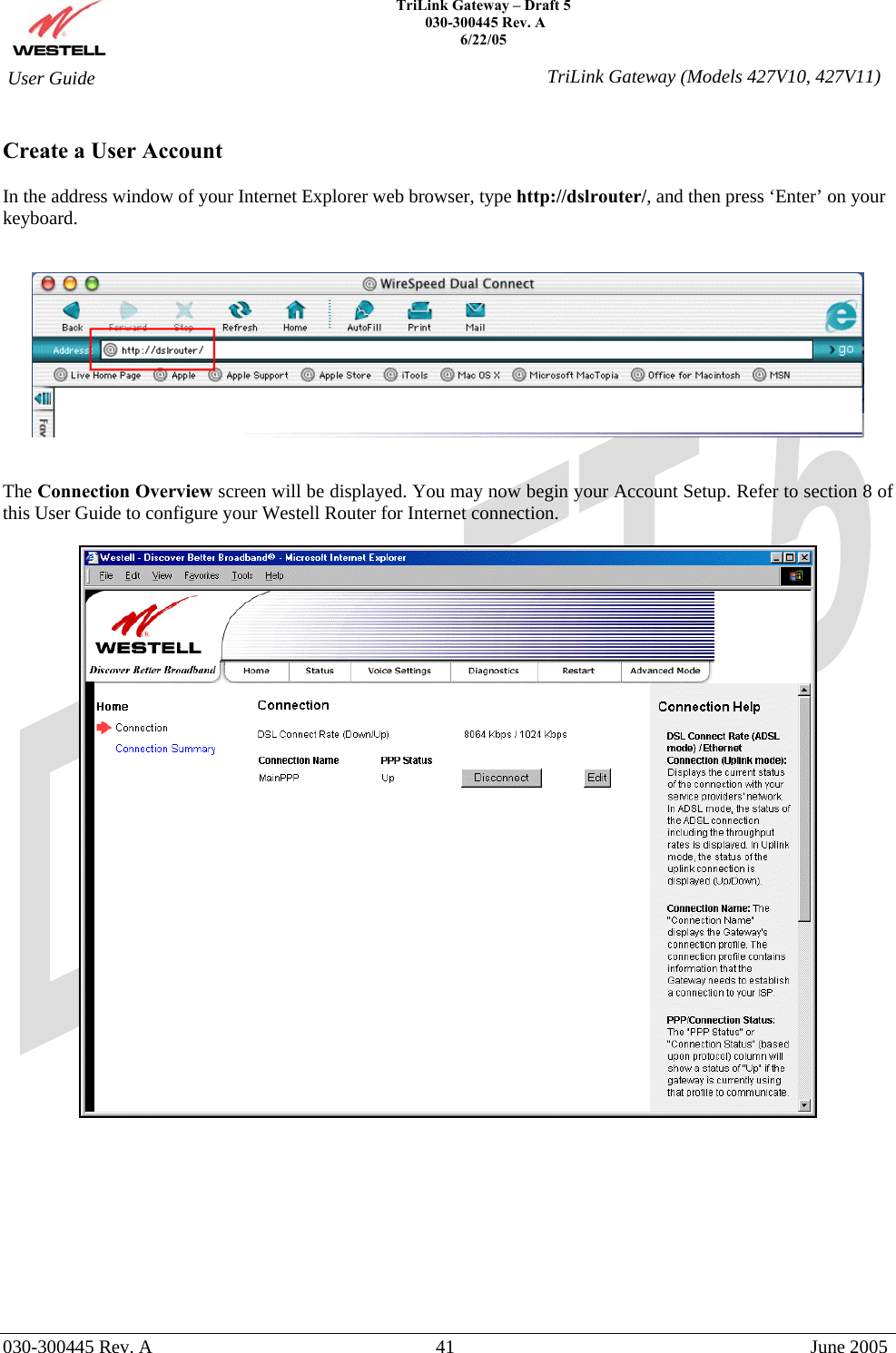
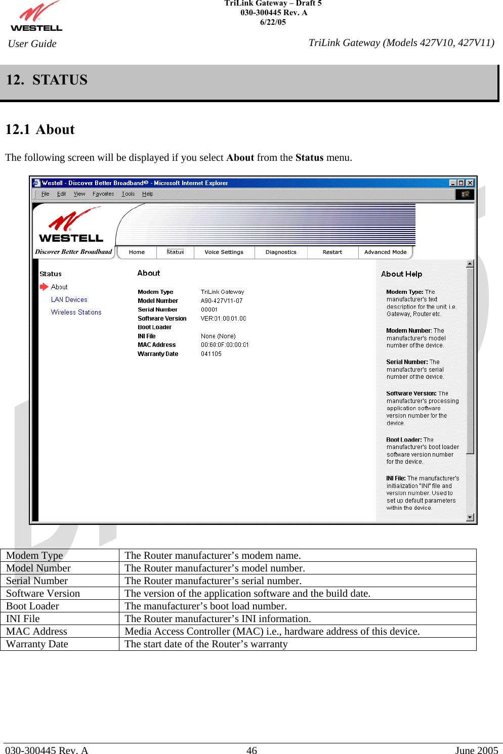

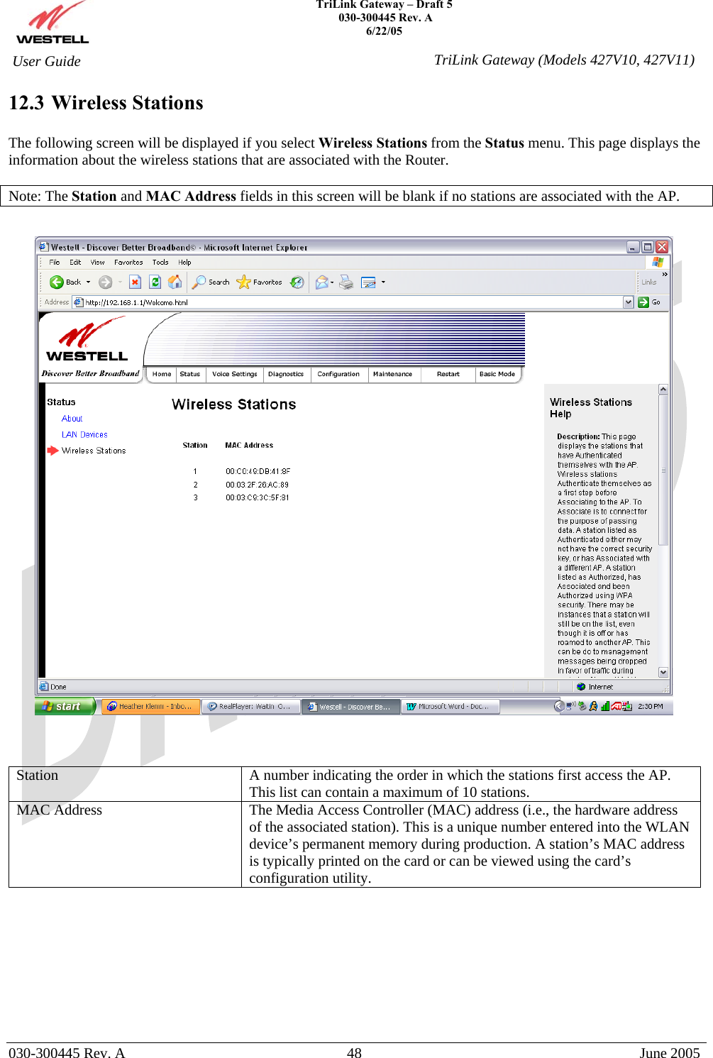

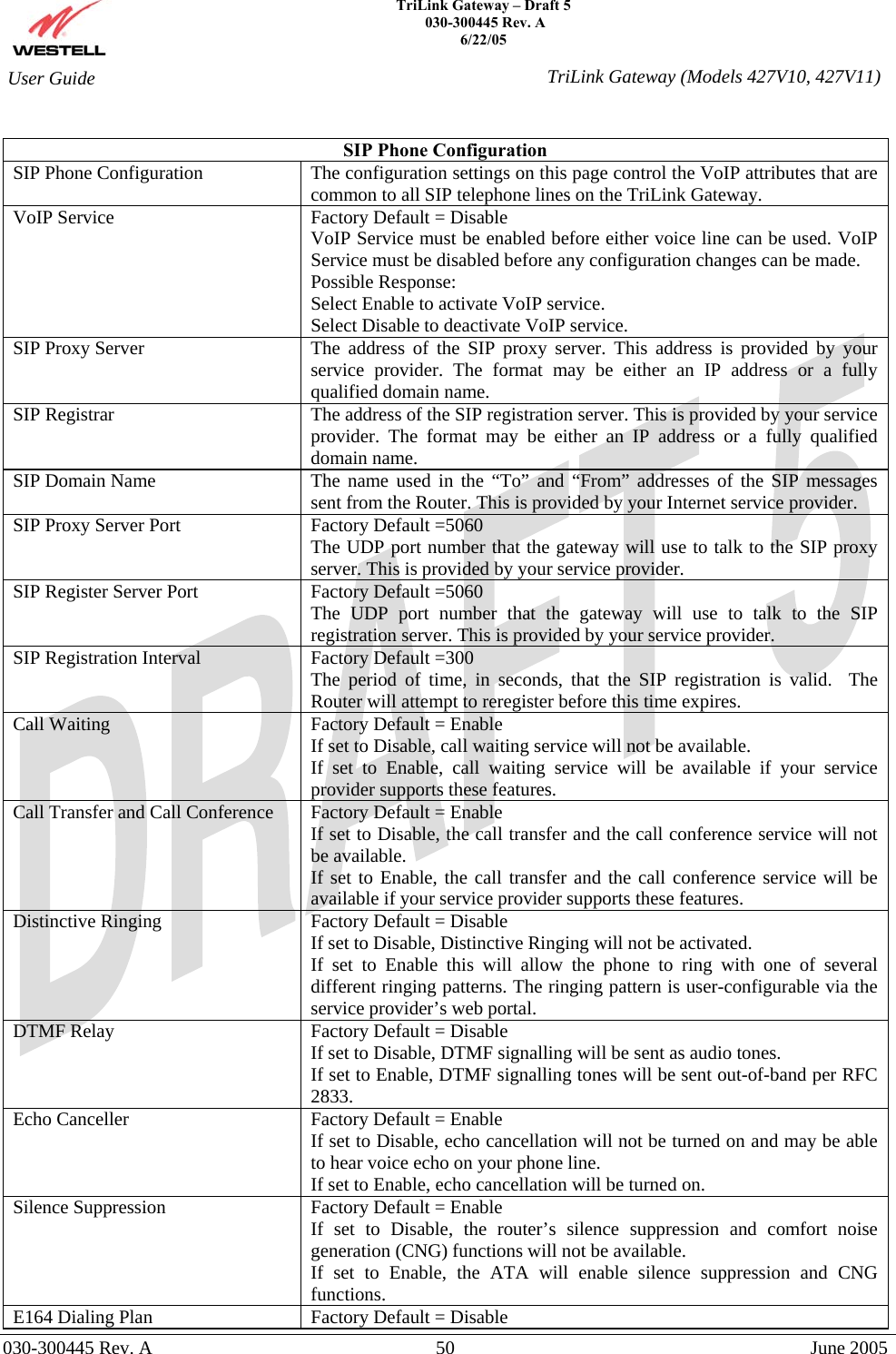
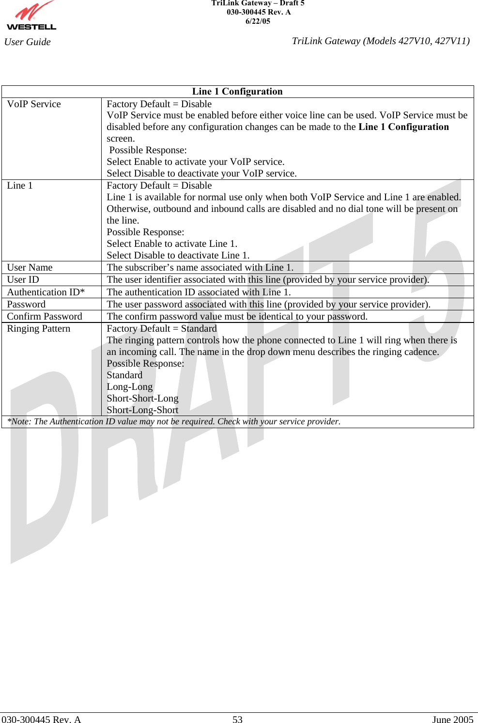
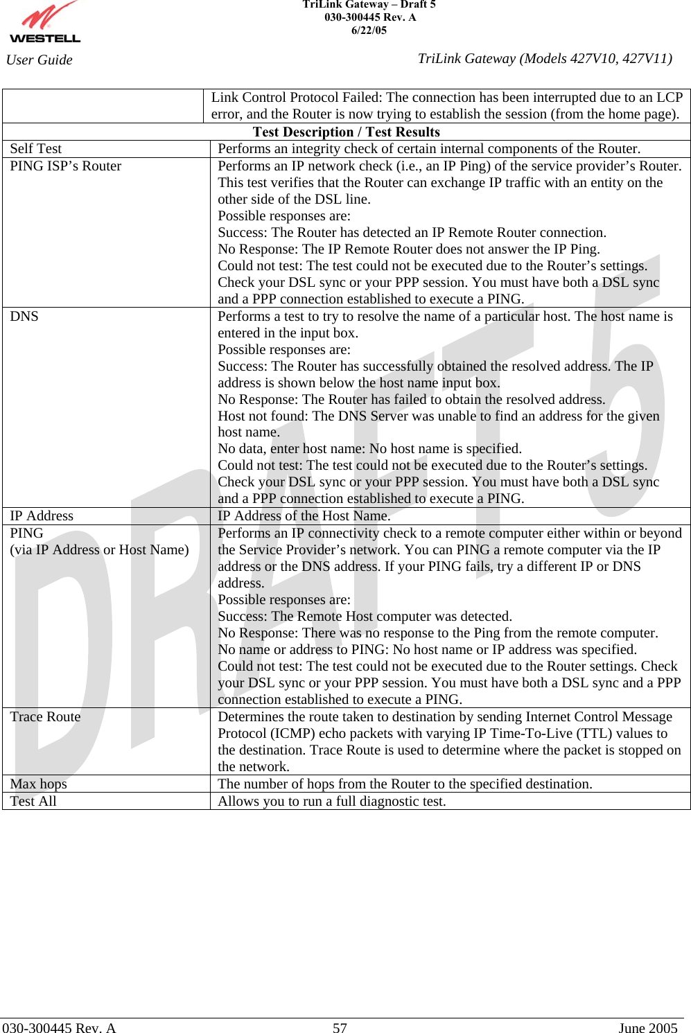
![TriLink Gateway – Draft 5 030-300445 Rev. A 6/22/05 030-300445 Rev. A 51 June 2005 User Guide TriLink Gateway (Models 427V10, 427V11)If set to Disable, the message headers in outbound INVITE messages will specify user addresses exactly as they are entered in the GUI. If set to Enable, the message headers in outbound INVITE messages will specify user addresses (i.e., phone numbers) in the E.164 format. (Note: It is recommended that you do not enable this option unless directed by your service provider.) 1st Choice Codec Factory Default = G.711µ The 1st choice CODEC (Coder/Decoder) specifies the preferred CODEC. The Router supports the following CODECs: G.711µ G.711A G.729A G.723.1 2nd Choice Codec Factory Default = None The 2nd choice CODEC (Coder/Decoder) specifies the second priority CODEC. If no second priority CODEC is desired select “None.” Possible Response: None G.711µ G.711A G.729A G.723.1 3rd Choice Codec Factory Default = None The 3rd choice CODEC (Coder/Decoder) specifies the third priority CODEC. If no third priority CODEC is desired select “None.” Possible Response: None G.711µ G.711A G.729A G.723.1 4th Choice Codec Factory Default = None The 4th choice CODEC (Coder/Decoder) specifies the lowest priority CODEC. If no fourth priority CODEC is desired select “None.” Possible Response: None G.711µ G.711A G.729A G.723.1 Local SIP Port Factory Default = 5060 The port number from which the TriLink sends SIP messages. Local RTP Base Port Factory Default =5090 The first UDP port number that the gateway will use to send the RTP voice packets. Digit Map You can configure the digit map string according to your dialing plan. The default digit map string is: 1XXXXXXXXXX|[2-9]XXXXXX|011. The individual digit maps are separated by the “|” character. The syntax is as follows X – Matches any single digit.](https://usermanual.wiki/Westell/A90427XXX-07.Users-Manual-Part-I/User-Guide-568738-Page-51.png)
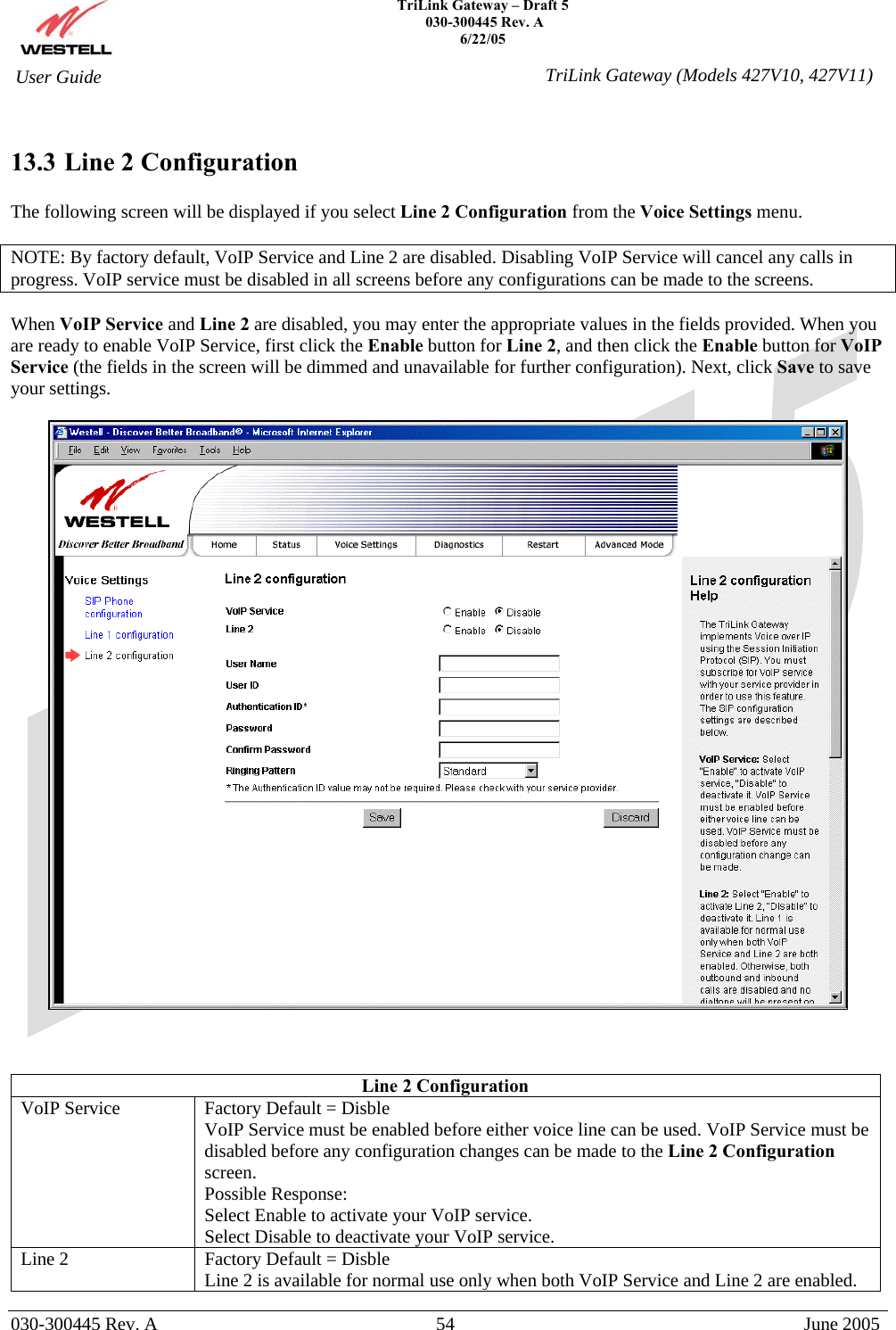
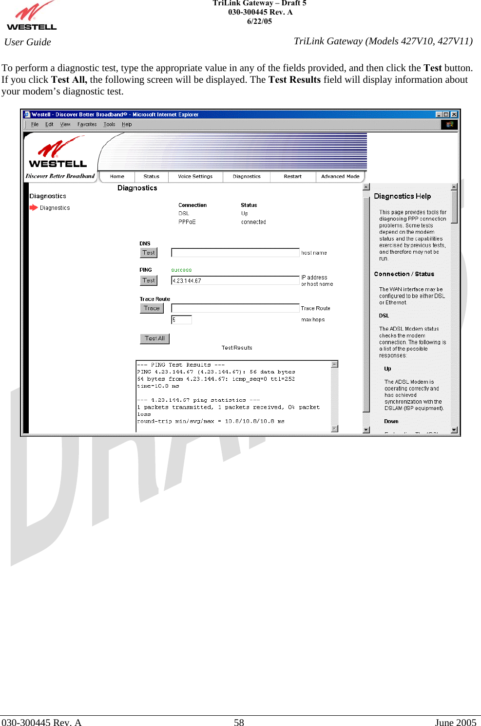
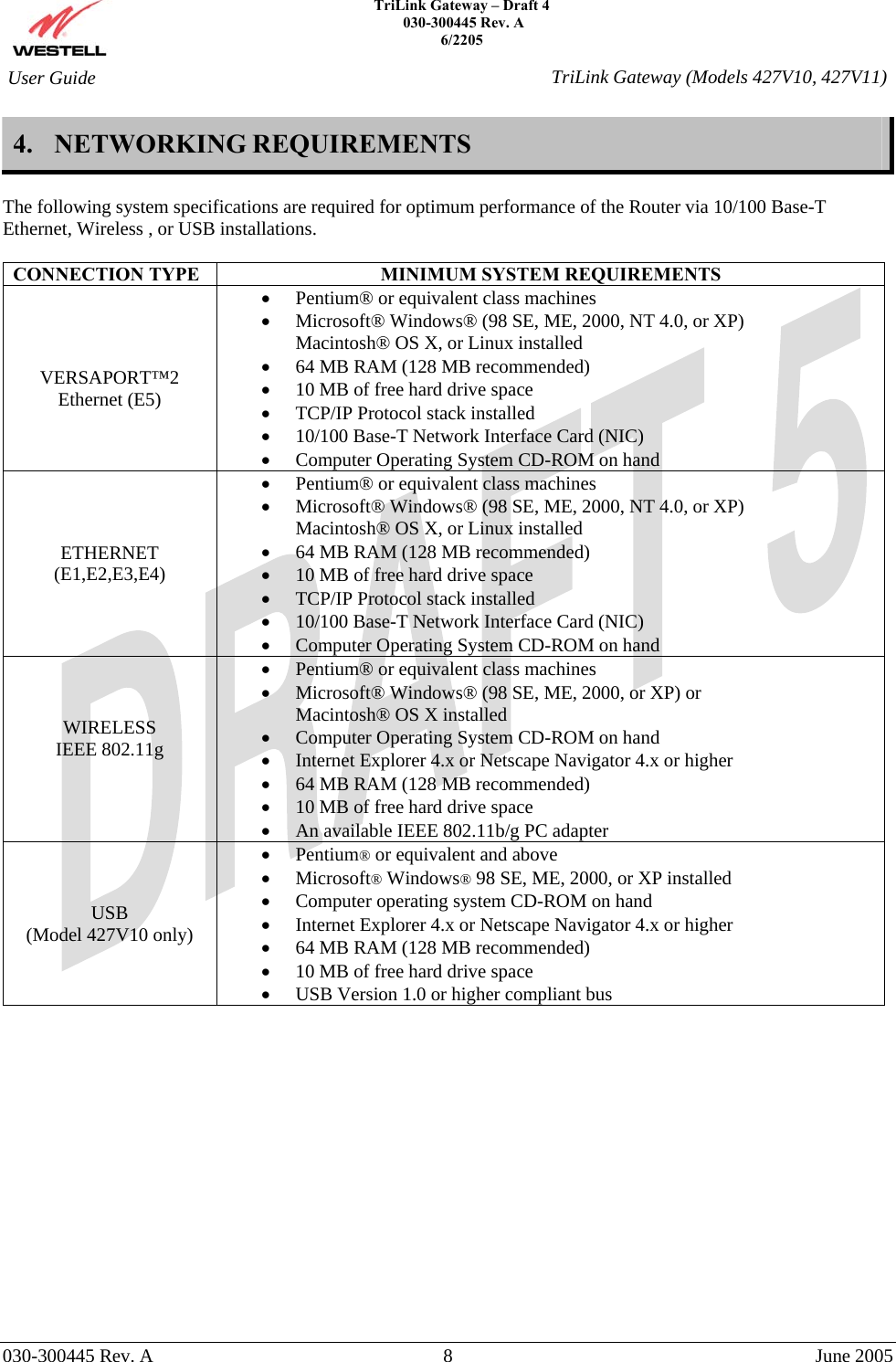
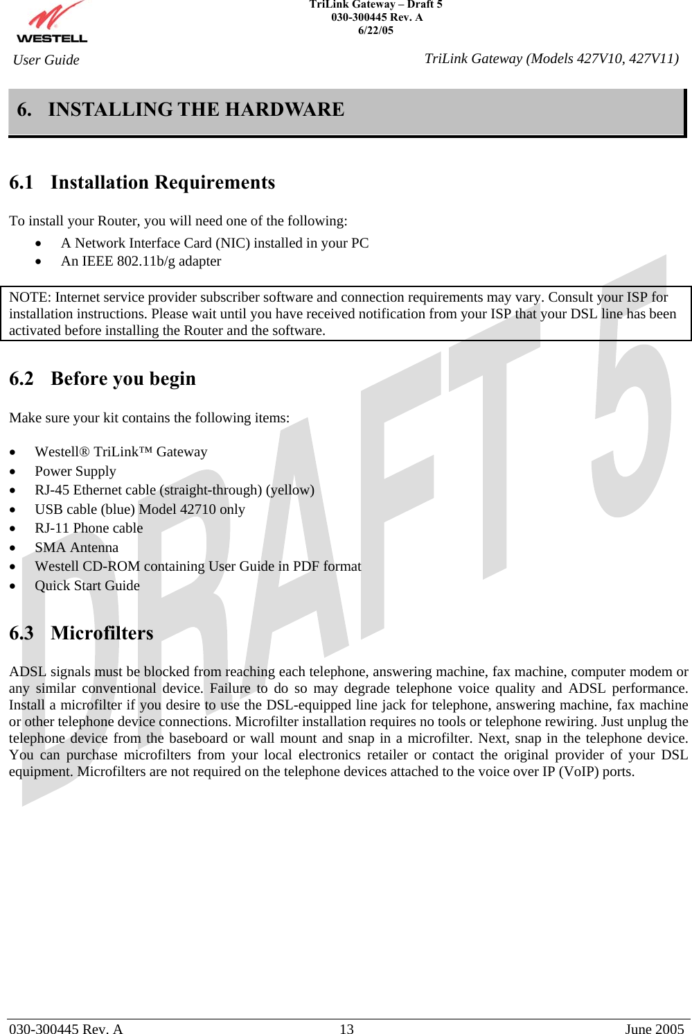
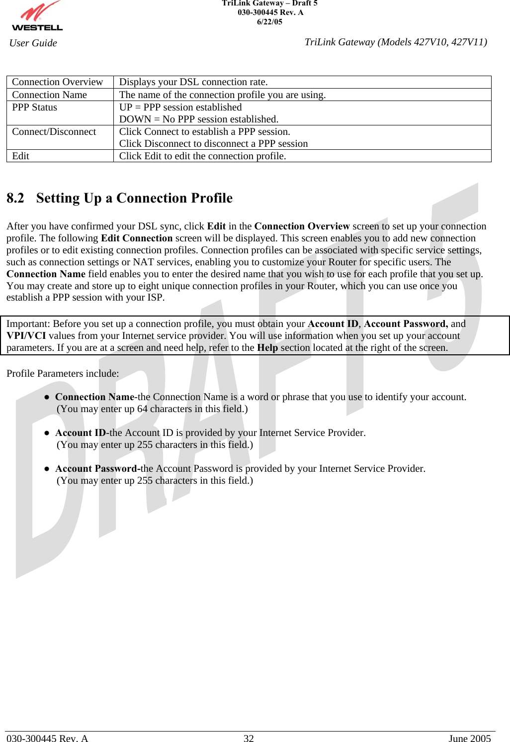
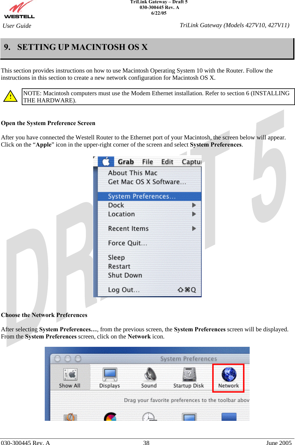
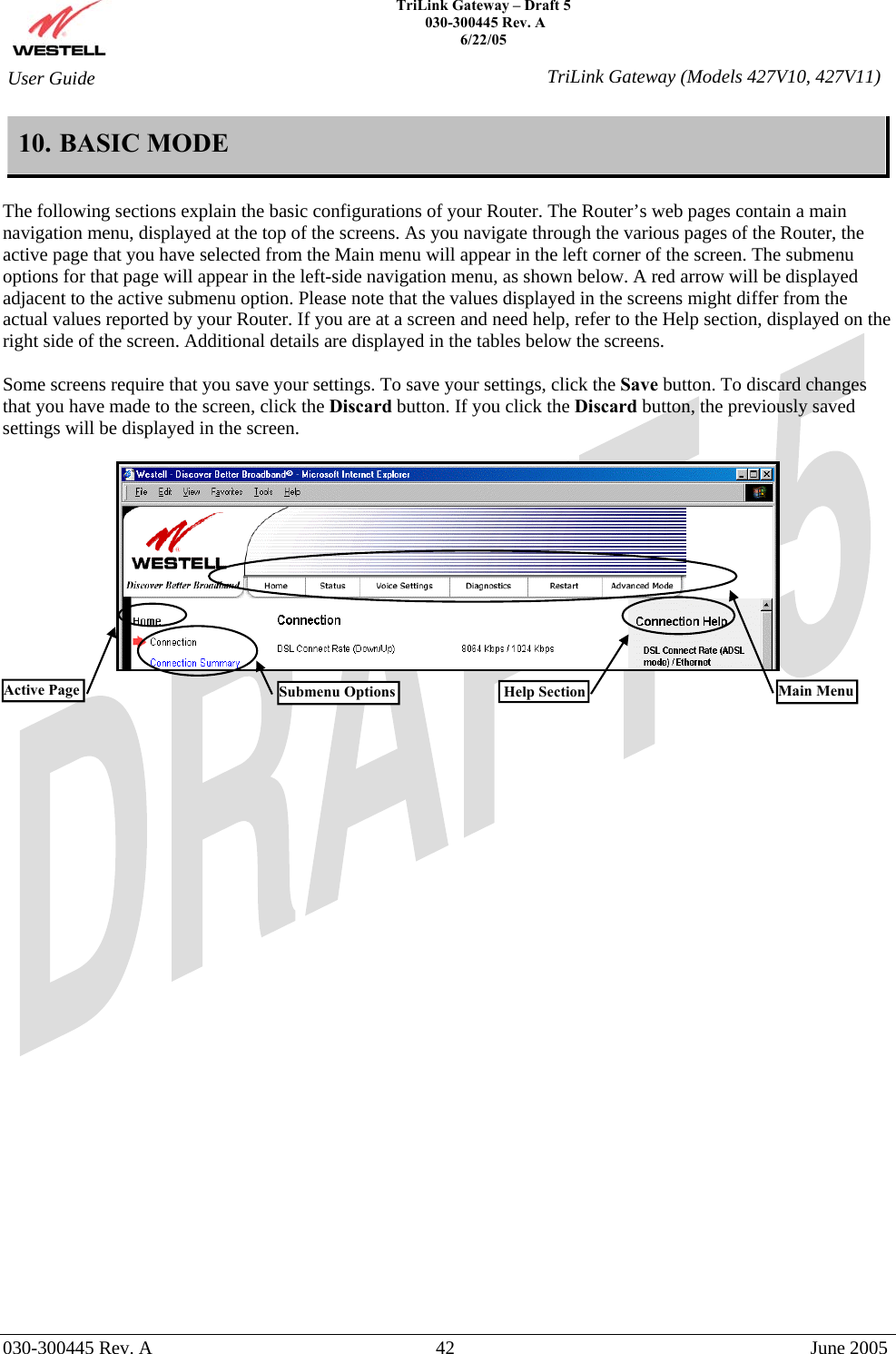
![TriLink Gateway – Draft 5 030-300445 Rev. A 6/22/05 030-300445 Rev. A 52 June 2005 User Guide TriLink Gateway (Models 427V10, 427V11)* – Represents the * character on you telephone keypad. In the example, the digit map *XX. supports feature code dialing. . – A period represents any arbitrary number of digits, including none. [2-9] – Any single digit in the specified range. [3,4,5] – Any single digit in the comma-separated list. SIP Debug Level Factory Default = 0 Possible Response: 0 = Fatal 1 = Error 2 = Warn 3 = Notice 4 = Info 5 = Dbg 6 = Dbgv 13.2 Line 1 Configuration The following screen will be displayed if you select Line 1 Configuration from the Voice Settings menu. NOTE: By factory default, VoIP Service and Line 1 are disabled. Disabling VoIP Service will cancel any calls in progress. VoIP service must be disabled in all screens before any configurations can be made to the screens. When VoIP Service and Line 1 are disabled, you may enter the appropriate values in the fields provided. When you are ready to enable VoIP Service, first click the Enable button for Line 1, and then click the Enable button for VoIP Service (the fields in the screen will be dimmed and unavailable for further configuration). Next, click Save to save your settings.](https://usermanual.wiki/Westell/A90427XXX-07.Users-Manual-Part-I/User-Guide-568738-Page-52.png)