Westell A90427XXX-07 Spread Spectrum Transmitter User Manual Part I
Westell Inc Spread Spectrum Transmitter Users Manual Part I
Westell >
Contents
- 1. Users Manual Part I
- 2. Users Manual Part II
Users Manual Part I

TriLink Gateway – Draft 5
030-300445 Rev. A
6/22/05
Copyright © 2005 Westell, Inc. 030-300445 Rev. A
Draft 5 contains VERSAPORT™2 and all new Advanced Config screens (w/ Port Triggering, Static NAT, Spanning
Tree, etc.)
TRILINK™ GATEWAY (MODEL 427V)
USER GUIDE

TriLink Gateway – Draft 4
030-300445 Rev. A
6/2205
030-300445 Rev. A 2 June 2005
User Guide TriLink Gateway (Models 427V10, 427V11)
TABLE OF CONTENTS
1. PRODUCT DESCRIPTION..................................................................................................................................5
2. SAFETY INSTRUCTIONS ..................................................................................................................................5
3. REGULATORY INFORMATION .......................................................................................................................6
3.1 FCC Compliance Note................................................................................................................................6
3.2 Canada Certification Notice .......................................................................................................................7
4. NETWORKING REQUIREMENTS ....................................................................................................................8
5. HARDWARE FEATURES...................................................................................................................................9
5.1 LED Indicators ...........................................................................................................................................9
5.2 Cable Connectors and Switch Locations ..................................................................................................10
5.3 Connector Descriptions ............................................................................................................................11
5.4 Pin-out Descriptions.................................................................................................................................12
6. INSTALLING THE HARDWARE.....................................................................................................................13
6.1 Installation Requirements.........................................................................................................................13
6.2 Before you begin ......................................................................................................................................13
6.3 Microfilters...............................................................................................................................................13
6.4 Hardware Installations..............................................................................................................................14
6.4.1 Installation via DSL.................................................................................................................................14
6.4.2 Installation via VERSAPORT™2 – Ethernet WAN Uplink....................................................................15
6.4.3 Connecting PCs via Wireless...................................................................................................................16
6.4.4 Connecting PCs via USB.........................................................................................................................17
6.4.5 VoIP Installation......................................................................................................................................17
7. INSTALLING THE USB DRIVERS..................................................................................................................18
7.1.1 CD-ROM Installation: .............................................................................................................................18
7.1.2 Installing the USB Drivers for Windows 98 SE ......................................................................................18
7.2 Installing the USB Drivers for Windows ME...........................................................................................24
7.3 Installing the USB Driver for Windows 2000 ..........................................................................................26
7.4 Installing the USB Driver for Windows XP.............................................................................................29
8. CONFIGURING THE ROUTER FOR INTERNET CONNECTION................................................................31
8.1 Confirming a DSL Sync ...........................................................................................................................31
8.2 Setting Up a Connection Profile...............................................................................................................32
8.3 Establishing a PPP Session.......................................................................................................................35
8.4 Disconnecting a PPP Session ...................................................................................................................37
9. SETTING UP Macintosh OS X...........................................................................................................................38
10. BASIC MODE.................................................................................................................................................42
11. HOME .............................................................................................................................................................43
11.1 Connection................................................................................................................................................43
11.2 Connection Summary...............................................................................................................................44
12. STATUS..........................................................................................................................................................46
12.1 About........................................................................................................................................................46
12.2 LAN Devices............................................................................................................................................47
12.3 Wireless Stations ......................................................................................................................................48
13. VOICE SETTINGS.........................................................................................................................................49
13.1 SIP Phone Configuration..........................................................................................................................49

TriLink Gateway – Draft 4
030-300445 Rev. A
6/2205
030-300445 Rev. A 3 June 2005
User Guide TriLink Gateway (Models 427V10, 427V11)
13.2 Line 1 Configuration ................................................................................................................................52
13.3 Line 2 Configuration ................................................................................................................................54
14. DIAGNOSTICS...............................................................................................................................................56
15. RESTART .......................................................................................................................................................59
16. ADVANCED MODE......................................................................................................................................61
17. CONFIGURATION ........................................................................................................................................62
17.1 Firewall Configuration .............................................................................................................................62
17.2 Port Forwarding Configuration.................................................................................................................63
17.3 Port Triggering .........................................................................................................................................67
17.4 ALG Configuration ..................................................................................................................................69
17.5 LAN Configuration ..................................................................................................................................70
17.5.1 DHCP.......................................................................................................................................................70
17.5.2 DNS .........................................................................................................................................................71
17.5.3 Public LAN – Multiple IP Address Passthrough .....................................................................................72
17.5.4 IP Passthrough – Single IP Address Passthrough ....................................................................................73
17.5.5 Static NAT...............................................................................................................................................78
17.5.6 Port Mapping ...........................................................................................................................................80
17.6 Spanning Tree...........................................................................................................................................81
17.7 WAN Configuration.................................................................................................................................82
17.7.1 VersaPort .................................................................................................................................................82
17.7.2 Private LAN – Configuring NAT ............................................................................................................83
17.7.3 Ethernet WAN Uplink .............................................................................................................................84
17.7.4 Public LAN – Multiple IP Address Passthrough .....................................................................................86
17.7.5 VCs..........................................................................................................................................................87
17.7.6 VPN .........................................................................................................................................................93
17.7.7 Routing Table ..........................................................................................................................................94
17.8 Wireless Configuration.............................................................................................................................95
17.8.1 Basic ........................................................................................................................................................95
17.8.2 Wireless Security.....................................................................................................................................97
17.8.3 MAC Filter.............................................................................................................................................100
17.8.4 Advanced Wireless Settings ..................................................................................................................103
18. MAINTENANCE..........................................................................................................................................104
18.1 Login Administration .............................................................................................................................104
18.2 Event Log ...............................................................................................................................................105
18.3 Firewall Log ...........................................................................................................................................107
18.4 Update Device........................................................................................................................................108
18.5 Remote Access .......................................................................................................................................109
18.6 Statistics..................................................................................................................................................110
18.6.1 Ethernet Port Statistics...........................................................................................................................110
18.6.2 Switch Ports Statistics............................................................................................................................111
18.6.3 Transceiver Statistics .............................................................................................................................112
18.6.4 USB Statistics ........................................................................................................................................113
18.6.5 Voice Statistics ......................................................................................................................................114
18.6.6 ATM Statistics.......................................................................................................................................115
18.6.7 Wireless Statistics..................................................................................................................................116

TriLink Gateway – Draft 4
030-300445 Rev. A
6/2205
030-300445 Rev. A 4 June 2005
User Guide TriLink Gateway (Models 427V10, 427V11)
19. NAT SERVICES...........................................................................................................................................117
20. PRODUCT SPECIFICATIONS....................................................................................................................121
21. TECHNICAL SUPPORT INFORMATION .................................................................................................123
22. WARRANTY AND REPAIRS.....................................................................................................................123
23. PUBLICATION INFORMATION................................................................................................................124
TriLink Gateway – Draft 4
030-300445 Rev. A
6/2205
030-300445 Rev. A 5 June 2005
User Guide TriLink Gateway (Models 427V10, 427V11)
1. PRODUCT DESCRIPTION
Your Westell® TriLink™ Gateway combines the functionality of a Voice over (VoIP) Analog Terminal Adapter
with that of a Westell® ADSL Gateway. The TriLink™ Gateway enables you to connect an analog phone to the
Gateway to make or receive phone calls over the Internet, and supports a variety of networking interfaces such as
wireless 802.11b/g, ADSL/2/2+, and Ethernet. The Gateway functions as a Router and enables you to connect
multiple PCs on your LAN to the Internet. The Gateway’s VersaPort™2 interface enables you to uplink your
Gateway to other ADSL network devices, and the 802.11 wireless interface enables you to establish a secure
wireless connection with mobile computing devices.
With the Westell® TriLink™ Gateway, you can to use the same phone line for simultaneous voice/fax
communications and high-speed Internet access, eliminating the need for dedicated phone lines for voice and data
needs. Your ADSL connection is “always-on,” ending the hassles of dial-up modems and busy signals, and
installation is easy ... no tools ... no headaches. Simply connect the hardware, apply power, and perform the simple
software configuration for your Gateway and you are on the Internet.
Hereafter, the Westell® TriLink™ Gateway will be referred to as the “Gateway” or the “Router.”
2. SAFETY INSTRUCTIONS
The following important safety instructions should be followed when using your telephone equipment.
WARNING: Please save these instructions.
Do not use this product near water, for example, near a bathtub, washbowl, kitchen sink or laundry tub, in a
wet basement or near a swimming pool.
Avoid using a telephone (other than a cordless type) during an electrical storm. There may be a remote risk
of electric shock from lightning.
Do not use the telephone to report a gas leak in the vicinity of the leak.
Do not connect this equipment in an environment that is unsuitable. The voice over IP (VoIP) ports of the
equipment are suitable for connection to intra-building or nonexposed wiring only.
Never install any telephone wiring during a lightning storm.
Never install telephone jacks in wet locations unless the jack is specifically designed for wet locations.
Never touch non-insulated telephone wires or terminals unless the telephone line has been disconnected at
the network interface.
Use caution when installing or modifying telephone lines.
WARNING
Risk of electric shock. Voltages up to 140 Vdc (with reference to ground) may
be present on telecommunications circuits.

TriLink Gateway – Draft 4
030-300445 Rev. A
6/2205
030-300445 Rev. A 6 June 2005
User Guide TriLink Gateway (Models 427V10, 427V11)
3. REGULATORY INFORMATION
3.1 FCC Compliance Note
(FCC ID: CH8-A90427XXX-07)
This equipment has been tested and found to comply with the limits for a Class B digital device, pursuant to Part 15
of the Federal Communication Commission (FCC) Rules. These limits are designed to provide reasonable protection
against harmful interference in a residential installation. This equipment generates, uses, and can radiate radio
frequency energy, and if not installed and used in accordance with the instructions, may cause harmful interference
to radio communications. However, there is no guarantee that interference will not occur in a particular installation.
If this equipment does cause harmful interference to radio or television reception, which can be determined by
turning the equipment OFF and ON, the user is encouraged to try to correct the interference by one or more of the
following measures:
• Reorient or relocate the receiving antenna.
• Increase the separation between the equipment and the receiver.
• Connect the equipment to a different circuit from that to which the receiver is connected.
• Consult the dealer or an experienced radio/TV technician for help.
Modifications made to the product, unless expressly approved by Westell Inc., could void the users’ right to
operate the equipment.
RF EXPOSURE
This device has been tested and complies with FCC RF Exposure (SAR) limits in typical laptop computer
configurations and this device can be used in desktop or laptop computers with side-mounted PCMCIA slots,
which can provide 1 cm separation distance from the antenna to the body of the user or a nearby person.
Thin laptop computers may need special attention to maintain antenna spacing while operating. This device
cannot be used with handheld PDAs (personal digital assistants). Use in other configurations may not ensure
compliance with FCC RF exposure guidelines. This device and its antenna must not be co-located or operate
in conjunction with another antenna or transmitter.
PART 68 – COMPLIANCE REGISTRATION
This equipment is designated to connect to the telephone network or premises wiring using a compatible modular
jack that is Part 68 compliant. An FCC compliant telephone cord and modular plug is provided with the equipment.
Refer to the installations instructions in this User Guide for details.
A plug and jack used to connect this equipment to the premises wiring and telephone network must comply with the
applicable FCC Part 68 rules and requirements adopted by the ACTA. A compliant telephone cord and modular plug
is provided with this product. It is designed to be connected to a compatible modular jack that is also compliant.
Refer to the installation instructions in this User Guide for details.
If this terminal equipment (Model 427V) causes harm to the telephone network, the telephone company may request
you to disconnect the equipment until the problem is resolved. The telephone company will notify you in advance if
temporary discontinuance of service is required. If advance notification is not practical, the telephone company will
notify you as soon as possible. You will be advised of your right to file a complaint with the FCC if you believe
such action is necessary. If you experience trouble with this equipment (Model 427V), do not try to repair the
equipment yourself. The equipment cannot be repaired in the field. Contact your ISP, or contact the original
provider of your DSL equipment.
The telephone company may make changes to their facilities, equipment, operations, or procedures that could affect
the operation of this equipment. If this happens, the telephone company will provide advance notice in order for you
to make the modifications necessary to maintain uninterrupted service.

TriLink Gateway – Draft 4
030-300445 Rev. A
6/2205
030-300445 Rev. A 7 June 2005
User Guide TriLink Gateway (Models 427V10, 427V11)
If your home has specially wired alarm equipment connected to the telephone line, ensure that the installation of this
equipment (Model 427V) does not disable your alarm equipment. If you have questions about what will disable
alarm equipment, consult your telephone company or a qualified installer. This equipment cannot be used on public
coin phone service provided by the telephone company. Connection of this equipment to party line service is subject
to state tariffs.
3.2 Canada Certification Notice
The Industry Canada label identifies certified equipment. This certification means that the equipment meets certain
telecommunications network protective, operations and safety requirements as prescribed in the appropriate
Terminal Equipment Technical Requirements document(s). The department does not guarantee the equipment will
operate to the user’s satisfaction.
This equipment meets the applicable Industry Canada Terminal Equipment Technical Specification. This is
confirmed by the registration number. The abbreviation, IC, before the registration number signifies that registration
was performed based on a Declaration of Conformity indicating that Industry Canada technical specification were
met. It does not imply that Industry Canada approved the equipment. The Ringer Equivalence Number (REN) is 0.0.
The Ringer Equivalence Number that is assigned to each piece of terminal equipment provides an indication of the
maximum number of terminals allowed to be connected to a telephone interface. The termination on an interface
may consist of any combination of devices subject only to the requirement that the sum of the Ringer Equivalence
Numbers of all the devices does not exceed five.
Before installing this equipment, users should ensure that it is permissible to be connected to the facilities of the
local Telecommunication Company. The equipment must also be installed using an acceptable method of
connection. The customer should be aware that compliance with the above conditions may not prevent degradation
of service in some situations. Connection to a party line service is subject to state tariffs. Contact the state public
utility commission, public service commission, or corporation commission for information.
If your home has specially wired alarm equipment connected to the telephone line, ensure that the installation of this
equipment (Model 427V) does not disable your alarm equipment. If you have questions about what will disable
alarm equipment, consult your telephone company or a qualified installer.
If you experience trouble with this equipment (Model 427V) do not try to repair the equipment yourself. The
equipment cannot be repaired in the field and must be returned to the manufacturer. Repairs to certified equipment
should be coordinated by a representative, and designated by the supplier. Refer to section 22 in this User Guide for
further details. The termination on an interface may consist of any combination of devices subject only to the
requirement that the sum of the Ringer Equivalence Numbers of all the devices does not exceed five.
Operation of this equipment (Model 427V) is subject to the following conditions: (1) This device may not cause
harmful interference, and (2) This equipment must accept any interference received, including interference that may
cause undesired operation.
To reduce potential radio interference to users when a detachable antenna is used with this equipment the antenna
type and its gain should be so chosen that the equivalent isotropically radiated power (EIRP) is not more than that
required for successful communication.”
Users should ensure, for their own protection, that the electrical ground connections of the power utility, telephone
lines, and internal, metallic water pipe system, if present, are connected together. This precaution may be
particularly important in rural areas.
CAUTION
Users should not attempt to make such connections themselves, but should contact the appropriate
electrical inspection authority, or electrician, as appropriate.

TriLink Gateway – Draft 4
030-300445 Rev. A
6/2205
030-300445 Rev. A 8 June 2005
User Guide TriLink Gateway (Models 427V10, 427V11)
4. NETWORKING REQUIREMENTS
The following system specifications are required for optimum performance of the Router via 10/100 Base-T
Ethernet, Wireless , or USB installations.
CONNECTION TYPE MINIMUM SYSTEM REQUIREMENTS
VERSAPORT™2
Ethernet (E5)
• Pentium® or equivalent class machines
• Microsoft® Windows® (98 SE, ME, 2000, NT 4.0, or XP)
Macintosh® OS X, or Linux installed
• 64 MB RAM (128 MB recommended)
• 10 MB of free hard drive space
• TCP/IP Protocol stack installed
• 10/100 Base-T Network Interface Card (NIC)
• Computer Operating System CD-ROM on hand
ETHERNET
(E1,E2,E3,E4)
• Pentium® or equivalent class machines
• Microsoft® Windows® (98 SE, ME, 2000, NT 4.0, or XP)
Macintosh® OS X, or Linux installed
• 64 MB RAM (128 MB recommended)
• 10 MB of free hard drive space
• TCP/IP Protocol stack installed
• 10/100 Base-T Network Interface Card (NIC)
• Computer Operating System CD-ROM on hand
WIRELESS
IEEE 802.11g
• Pentium® or equivalent class machines
• Microsoft® Windows® (98 SE, ME, 2000, or XP) or
Macintosh® OS X installed
• Computer Operating System CD-ROM on hand
• Internet Explorer 4.x or Netscape Navigator 4.x or higher
• 64 MB RAM (128 MB recommended)
• 10 MB of free hard drive space
• An available IEEE 802.11b/g PC adapter
USB
(Model 427V10 only)
• Pentium® or equivalent and above
• Microsoft® Windows® 98 SE, ME, 2000, or XP installed
• Computer operating system CD-ROM on hand
• Internet Explorer 4.x or Netscape Navigator 4.x or higher
• 64 MB RAM (128 MB recommended)
• 10 MB of free hard drive space
• USB Version 1.0 or higher compliant bus

TriLink Gateway – Draft 5
030-300445 Rev. A
6/22/05
030-300445 Rev. A 9 June 2005
User Guide TriLink Gateway (Models 427V10, 427V11)
5. HARDWARE FEATURES
5.1 LED Indicators
This section explains the LED States and Descriptions of your Router. LED indicators are used to verify the unit’s
operation and status.
LED States and Descriptions
LED State Description
Solid Green Router power is ON.
OFF Router power is OFF.
POWER
Solid Red
POST (Power On Self Test), Failure (not bootable) or Device
Malfunction. Note: The Power LED should be red no longer
than two seconds after the power on self test passes.
Solid Green
Powered device is connected to the associated port (includes
devices with wake-on LAN capability where slight voltage is
supplied to an Ethernet connection).
Flashing Green 10/100 Base-T Ethernet LAN activity is present (LAN traffic in
either direction).
ETHERNET
(Ethernet LAN)
E1, E2, E3, E4
OFF Router power is OFF, no cable or no powered device is
connected to the associated port.
Solid Green
Powered device is connected to the associated port (includes
devices with wake-on LAN capability where slight voltage is
supplied to an Ethernet connection).
Flashing Green 10/100 Base-T Ethernet WAN activity is present (WAN traffic
in either direction).
VersaPort™2
(E5)
Off Router power is OFF, no cable, or no powered device is
connected to the associated port.
Solid Green Wireless is enabled and functioning.
Flashing Green Wireless LAN activity present (traffic in either direction).
WIRELESS
Off Wireless is disabled or not functioning.
Solid Green SIP registration succeeded. Attached device is registered with
VoIP server.
Flashing Green Attached device is attempting to establish a VoIP call.
Telephone 1
Off Router power off, line not provisioned, line not registered with
VoIP server.
Solid Green SIP registration succeeded. Attached device is registered with
VoIP server.
Flashing Green Attached device is attempting to establish a VoIP call.
Telephone 2
Off Router power off, line not provisioned, line not registered with
VoIP server.
Flashing Green Message Waiting.
Message Waiting 1
(Line 1 message waiting) Off No Message.
Flashing Green Message Waiting.
Message Waiting 2
(Line 2 message waiting) Off No Message.
Solid Green USB link established
Flashing Green Transmit or Receive Activity
USB
(Model 427V10 only) OFF No USB link established
Solid Green Good DSL sync.
DSL
Flashing Green DSL attempting to sync.
TriLink Gateway – Draft 5
030-300445 Rev. A
6/22/05
030-300445 Rev. A 10 June 2005
User Guide TriLink Gateway (Models 427V10, 427V11)
Solid Amber OFF Router is in safeboot mode.
Off Router power is OFF.
Solid Green Internet link established.
Flashing Green
IP connection established and IP Traffic is passing through
device (in either direction).
Note: If the IP or PPP session is dropped due to an idle timeout,
the light will remain solid green, if an ADSL connection is still
present.
If the session is dropped for any other reason, the light is turned
OFF. The light will turn red when it attempts to reconnect and
DHCP or PPP fails).
Solid Red
Device attempted to become IP connected and failed (no DHCP
response, no PPP response, PPP authentication failed, no IP
address from IPCP, etc.).
INTERNET
OFF Modem power is OFF, Modem is in Bridge Mode, or the
connection is not present.
NOTE: Safe Boot is reflected when the Power and Internet LED’s are both Red and all other LED’s are off.
5.2 Cable Connectors and Switch Locations
• DSL connector (RJ-11)
• USB connector (Model 427V10 only)
• VERSAPORT™2 connector (RJ-45) yellow
• (4) Ethernet connector (RJ-45)
• (2) POTS connector (RJ-11)
• Power connector (barrel)
• ON/OFF Switch
• Wireless IEEE 802.11b/g SMA connector and antenna
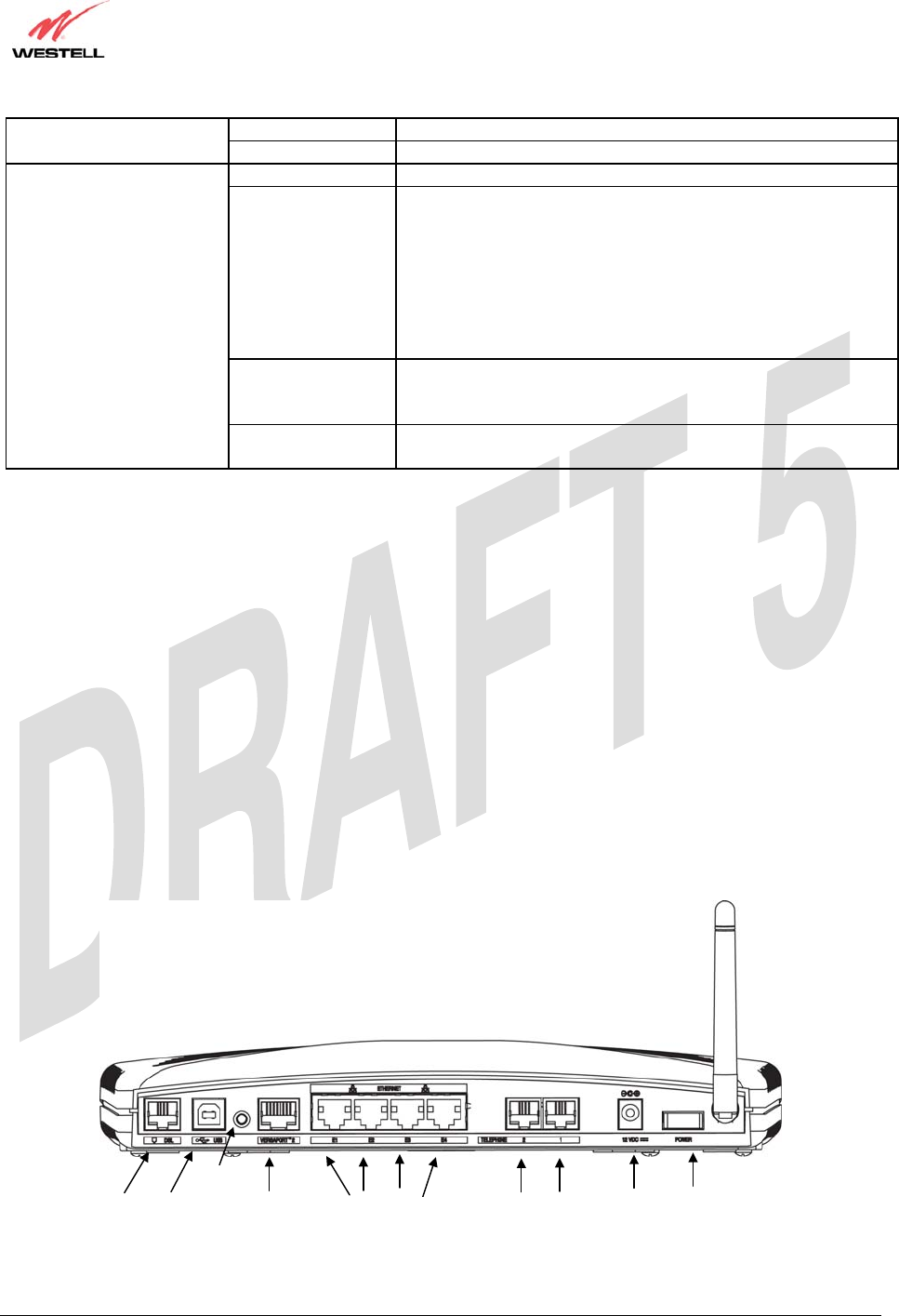
Figure 1. Rear View of TriLink™ Gateway (Model 427V10)
DSL VERSAPORT™ 2 ETHERNET
(
E1
,
E2
,
E3
,
E4
)
TELEPHONE 1 and 2 12 VDC POWE
R
USB
RESET
TriLink Gateway – Draft 5
030-300445 Rev. A
6/22/05
030-300445 Rev. A 11 June 2005
User Guide TriLink Gateway (Models 427V10, 427V11)
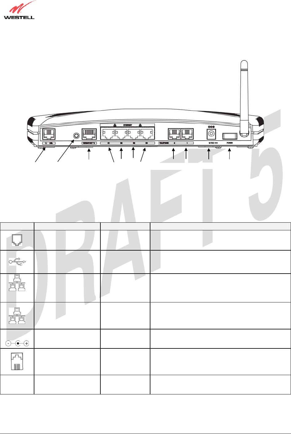
Figure 2. Rear View of TriLink™ Gateway (Model 427V11)
5.3 Connector Descriptions
The following chart displays the connector types for the TriLink™ Gateway.
SYMBOL NAME TYPE FUNCTION
DSL LINE RJ-11 Connects to an ADSL-equipped telephone jack or
DSL connection of a POTS splitter.
USB 4-pin USB Series
B connector Connects the USB device to the PC.
(Model 427V10 only)
VERSAPORT™2 RJ-45
The VersaPort™2 can function as a 10/100 Base-T
Ethernet connection to a WAN-side networking
device. (e.g., xDSL, etc.), a DMZ LAN Port, or a fifth
Ethernet LAN Port, depending on the configuration.
ETHERNET RJ-45 10/100 Base-T Ethernet Connection to PC or Hub.
12 VDC
POWER Barrel connector Connection to DC (12V) Power Connector .
TELEPHONE 1 and 2 RJ-11 Telephone Port connection to phone cable.
Wireless ANTENNA SMA connector
and antenna Connects to wireless IEEE 802.11b/g device.
DSL VERSAPORT™ 2 ETHERNET
(
E1
,
E2
,
E3
,
E4
)
12 VDC POWE
R
RESET TELEPHONE 1 and 2

TriLink Gateway – Draft 5
030-300445 Rev. A
6/22/05
030-300445 Rev. A 12 June 2005
User Guide TriLink Gateway (Models 427V10, 427V11)
5.4 Pin-out Descriptions
The following table lists the Router’s port pin-outs and descriptions.
Port Pin-out Description
1,2,5,6 Not Used
3 DSL TIP
DSL
4 DSL Ring
1 VBUS/Vcc
2 Data –
3 Data +
USB
(Model 427V10 only)
4 Ground
1 Rx+
2 Rx-
3 Tx+
4,5,7,8 Not Used
VERSAPORT™2
(Ethernet E5)
6 Tx-
1 Rx+
2 Rx-
3 Tx+
4,5,7,8 Not Used
ETHERNET
E1, E2, E3, E4
6 Tx-
1,2,5,6 Not Used
3 POTS TIP
RJ-11
TELEPHONE 1 and 2 4 POTS Ring

TriLink Gateway – Draft 5
030-300445 Rev. A
6/22/05
030-300445 Rev. A 13 June 2005
User Guide TriLink Gateway (Models 427V10, 427V11)
6. INSTALLING THE HARDWARE
6.1 Installation Requirements
To install your Router, you will need one of the following:
• A Network Interface Card (NIC) installed in your PC
• An IEEE 802.11b/g adapter
NOTE: Internet service provider subscriber software and connection requirements may vary. Consult your ISP for
installation instructions. Please wait until you have received notification from your ISP that your DSL line has been
activated before installing the Router and the software.
6.2 Before you begin
Make sure your kit contains the following items:
• Westell® TriLink™ Gateway
• Power Supply
• RJ-45 Ethernet cable (straight-through) (yellow)
• USB cable (blue) Model 42710 only
• RJ-11 Phone cable
• SMA Antenna
• Westell CD-ROM containing User Guide in PDF format
• Quick Start Guide
6.3 Microfilters
ADSL signals must be blocked from reaching each telephone, answering machine, fax machine, computer modem or
any similar conventional device. Failure to do so may degrade telephone voice quality and ADSL performance.
Install a microfilter if you desire to use the DSL-equipped line jack for telephone, answering machine, fax machine
or other telephone device connections. Microfilter installation requires no tools or telephone rewiring. Just unplug the
telephone device from the baseboard or wall mount and snap in a microfilter. Next, snap in the telephone device.
You can purchase microfilters from your local electronics retailer or contact the original provider of your DSL
equipment. Microfilters are not required on the telephone devices attached to the voice over IP (VoIP) ports.

TriLink Gateway – Draft 5
030-300445 Rev. A
6/22/05
030-300445 Rev. A 14 June 2005
User Guide TriLink Gateway (Models 427V10, 427V11)
6.4 Hardware Installations
NOTE: If you are using the Router in conjunction with an Ethernet Hub or Switch, refer to the manufacturer’s
instructions for proper installation and configuration. When using a Microfilter, be certain that the DSL phone cable
is connected to the “DSL/HPN” non-filtered jack. Please wait until you have received notification from your ISP that
your DSL line has been activated before installing the Router. Westell recommends the use of a surge suppressor
to protect equipment attached to the power supply. An additional Ethernet cable may be required depending on
the installation method you are using. Ethernet cables can be purchased at your local computer hardware retailer.
6.4.1 Installation via DSL
IMPORTANT: Before you connect via 10/100 Base-T, you must have an available Ethernet card installed in
your computer. If your Ethernet card does not auto-negotiate, you must set it to half duplex. Refer to the
Ethernet card manufacturer’s instructions for installing and configuring your Ethernet card.
1. Connect the DSL phone cable from the connector marked DSL on the rear panel of the Router to the DSL-
equipped telephone line jack on the wall. IMPORTANT: Do not use a DSL filter on this connection. You must
use the phone cord that was provided with the kit.
2. Connect the yellow Ethernet cable (provided with your kit) from any one of the Ethernet jacks marked
ETHERNET on the rear panel of the Router to the Ethernet port on your computer. Repeat this step to connect
up to three additional PCs to your Westell Router.
NOTE: When using the yellow VERSAPORT™2 jack in Private LAN mode, you may connect either the yellow
Ethernet cable (provided with your kit) or any other Ethernet cable to the VERSAPORT™2 jack as the
VERSAPORT™2 jack will function as a fifth Ethernet switch. You may also connect to any of the four black
Ethernet jacks on the rear panel of the Router as they serve as an Ethernet switch.
3. Connect the power supply cord to the power connector marked 12 VDC on the rear panel of the Router. Plug the
other end of the power supply into a wall socket, and then turn on the power switch (if it is not already turned on).
4. Check to see if the DSL LED is solid green. If the DSL LED is solid green, the Router is functioning properly.
5. Check to see if the Ethernet LED is solid green. Solid green indicates that the Ethernet connection is functioning
properly.
6. Check to see if the Internet LED is solid green. Solid green indicates that an Internet link has been established.
Congratulations! You have completed the DSL installation for your Router. No software installation is required when
using an Ethernet only connection. You must now proceed to section 8, “Configuring the Router for Internet
Connection.”
!

TriLink Gateway – Draft 5
030-300445 Rev. A
6/22/05
030-300445 Rev. A 15 June 2005
User Guide TriLink Gateway (Models 427V10, 427V11)
6.4.2 Installation via VERSAPORT™2 – Ethernet WAN Uplink
1. Connect the yellow Ethernet cable (provided with your kit) from the Ethernet jack marked VERSAPORT™2
on the rear panel of the Router to the Ethernet port on the attached ADSL device, and then power up the attached
ADSL device.
2. Connnect the attached ADSL device to the ADSL-equipped jack on the wall. IMPORTANT: If the attached
ADSL device is a Router, do not use a DSL filter on this connection. You must use the phone cord that was
provided with your kit. (Note: The Router’s DSL transceiver will not be used when the Router is in Ethernet
WAN UPLINK mode.) Refer to section 17.7.3 for the VERSAPORT™2 configuration parameters.
3. Connect an Ethernet cable from any one of the four Ethernet jacks marked ETHERNET on the rear panel of the
Router to the Ethernet port on your computer. Repeat this step to connect up to three additional PCs to the
Router.
NOTE: You may connect to any of the four Ethernet jacks on the rear panel of the Router as they serve as an
Ethernet switch.
4. Connect the power supply cord to the power connector marked 12 VDC on the rear panel of the Router. Plug the
other end of the power supply into a wall socket, and then turn on the power switch (if it is not already turned
on).
5. Check to see if the VERSAPORT™2 LED is solid green. Solid green indicates that the VERSAPORT™2
connection is functioning properly. (The Router’s LAN and WAN traffic will be uplinked to the attached ADSL
device.)
Note: You may need to set the VERSAPORT™2 to uplink mode. Refer to section 17.7 “WAN Configuration,”
for instructions.
6. Check to see if the Ethernet LED is solid green. Solid green indicates that the Ethernet connection is functioning
properly.
7. Check to see if the Internet LED is solid green. Solid green indicates that the Internet link has been established.
Congratulations! You have completed the VERSAPORT™2 - Ethernet WAN Uplink installation for your Router. You
must now proceed to section 8, “Configuring the Router for Internet Connection.”

TriLink Gateway – Draft 5
030-300445 Rev. A
6/22/05
030-300445 Rev. A 16 June 2005
User Guide TriLink Gateway (Models 427V10, 427V11)
6.4.3 Connecting PCs via Wireless
IMPORTANT: If you are connecting to the Router via a wireless network adapter, the SSID must be the same for
both the Router and your PC’s wireless network adapter. The default SSID for the Router is the serial number of the
unit (located below the bar code on the bottom of the unit and also on the Westell shipping carton). Locate and run
the utility software provided with your PC’s Wireless network adapter and enter the SSID value. The PC’s wireless
network adapter must be configured with the SSID (in order to communicate with the Router) before you begin the
account setup and configuration procedures. Later, for privacy you can change the SSID by following the procedures
outlined in section 17.8 (Wireless Configuration).
IMPORTANT: Client PCs can use any Wireless Fidelity (Wi-Fi) 802.11b/g/g+ certified card to communicate with
the Router. The Wireless card and Router must use the same security code type. If you use WPA-PSK or WEP
wireless security, you must configure your computer’s wireless adapter for the security code that you use. You
can access the settings in the advanced properties of your wireless network adapter.
To network the Router to additional computers in your home or office using a wireless installation, you will need to
confirm the following:
1. Ensure that an 802.11b/g wireless network adapter has been installed in each PC on your wireless network.
2. Install the appropriate drivers for your Wireless IEEE802.11b or IEEE802.11g adapter.
3. Make sure the SMA antenna connector is loose. Orient the antenna in the proper configuration. Then, tighten the
antenna knob to lock it into place.
4. Connect the DSL phone cable from the connector marked DSL on the rear panel of the Router to the DSL-
equipped telephone line jack on the wall. IMPORTANT: Do not use a DSL filter on this connection. You must
use the phone cord that was provided with the Router kit.
5. Connect the power supply cord to the power connector marked 12 VDC on the rear panel of the Router. Plug the
other end of the power supply into a wall socket, and then turn on the power switch (if it is not already turned
on).
6. Check to see if the DSL LED is solid green. If the DSL LED is solid green, the Router is functioning properly.
7. Check to see if the Router’s Wireless LED is solid green. This means that the Wireless interface is functioning
properly.
8. Check to see if the Internet LED is solid green. Solid green indicates that an Internet link as been established.
Congratulations! You have completed the Wireless installation for your Router. You must now proceed section 8,
“Configuring the Router for Internet Connection.”

TriLink Gateway – Draft 5
030-300445 Rev. A
6/22/05
030-300445 Rev. A 17 June 2005
User Guide TriLink Gateway (Models 427V10, 427V11)
6.4.4 Connecting PCs via USB
Westell recommends using the Router via Wireless or Ethernet connections. However, if you choose to connect via
USB, you must follow the instructions in this section.
NOTE: The USB installation will not function for Macintosh computers. Macintosh computers must install
via Ethernet connection. See section 6.4.1 for Ethernet installation instructions.
1. Connect the DSL phone cable from the jack marked on the rear panel of the Router to the DSL-equipped
telephone line jack on the wall. IMPORTANT: Do not use a DSL filter on this connection. You must use the
phone cord that was provided with the kit.
2. Connect the blue USB cable from the USB connector marked on the rear panel of the Router to the
USB port on the PC.
3. Connect the power supply cord to the power connector marked 12 VDC on the rear panel of the Router. Plug the
other end of the power supply into a wall socket, and then turn on the power switch (if it is not already turned
on).
4. Install the USB drivers according to the procedures outlined in section 7 and then return to this step to complete
the instructions in this section. (Note: The USB driver software is required for your USB connection.)
5. Check to see if the USB LED is solid green. Solid green indicates that the USB connection is functioning
properly.
6. Check to see if the DSL LED is solid green. If the DSL LED is solid green, the Router is functioning properly.
7. Check to see if the Internet LED is solid green. Solid green indicates that an Internet link as been established
Congratulations! You have completed the USB hardware installation for your Router (including the installation of
USB driver software needed for your USB connection). You must now proceed to section 8, “Configuring the Router
for Internet Connection.”
6.4.5 VoIP Installation
1. Install the Router as described in one of the preceding installation instructions.
2. Connect the cable from your telephone to one of the jacks marked TELEPHONE 1 or TELEPHONE 2 on the
rear panel of the Router.
3. Check to see if the Internet LED is solid green. Solid green indicates that the Internet link has been established.
VoIP services will not be available if you do not have an Internet connection.
4. For VoIP services, you must enter SIP Registration Server information into the router before the LINE 1 or
LINE 2 LED lights. Refer to section 13 (Voice Settings) for details on VoIP configuration. After you have
registered with the SIP Server, check to see if the TELEPHONE 1 or TELEPHONE 2 LED is solid green.
Congratulations! You have completed the hardware installation for your VoIP connection. Refer to section 13, “Voice
Settings,” for details on SIP Phone configuration.
!
TriLink Gateway – Draft 5
030-300445 Rev. A
6/22/05
030-300445 Rev. A 18 June 2005
User Guide TriLink Gateway (Models 427V10, 427V11)
7. INSTALLING THE USB DRIVERS
If you are using only Ethernet or Wireless connections, USB driver installation is not necessary. The Microsoft®
Plug and Play auto-detect feature recognizes when new hardware has been installed. After you connect the Router to
the PC, the Router will be detected automatically.
Before you begin the USB software installation, determine which operating system is installed on your PC, and then
follow the installation instructions that match your operating system. When you have completed the procedures in
this section, return to section 6.4.4 to complete the instructions on connecting PCs via USB. The following table
provides a reference to the USB driver installation instructions.
Your Operating System Refer to this section for USB driver instructions
Windows 98 SE Installing the USB Driver for Windows 98 SE
Windows ME Installing the USB Driver for Windows ME
Windows 2000 Installing the USB Driver for Windows 2000
Windows XP Installing the USB Driver for Windows XP
7.1.1 CD-ROM Installation:
1. Place the CD-ROM that you received in your kit into the CD-ROM drive of the PC that is connected to the USB
port.
2. Verify the connection to the computer by observing the state of the USB LED. Once the USB drivers have been
installed, the USB LED should be solid green. Solid green indicates a USB connection has been established.
3. Go to the USB driver installation section that matches your operating system (refer to the preceding table) and
follow the procedures outlined in that section.
NOTE: The actual information displayed in the USB screens may vary according to product.
7.1.2 Installing the USB Drivers for Windows 98 SE
IMPORTANT: Confirm that the CD-ROM provided with your kit is inserted in the appropriate
drive before continuing this installation.
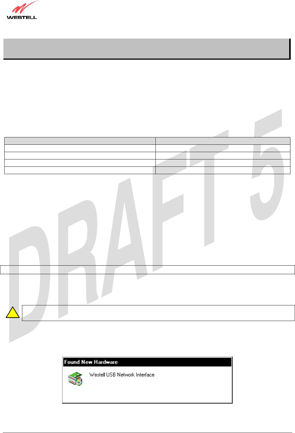
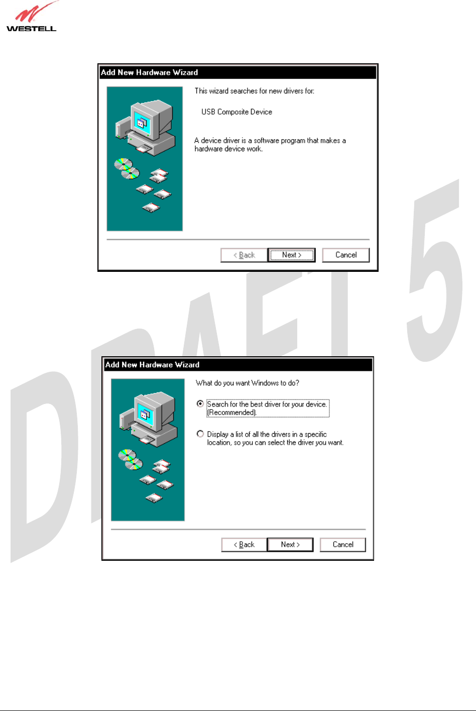
1. Windows 98 SE: After you connect the Router to your PC, the Found New Hardware window will appear
(Figure 3). After a brief delay, the Add New Hardware Wizard window will appear (Figure 4) Click Next.
Figure 3. Windows 98 SE
!
TriLink Gateway – Draft 5
030-300445 Rev. A
6/22/05
030-300445 Rev. A 20 June 2005
User Guide TriLink Gateway (Models 427V10, 427V11)
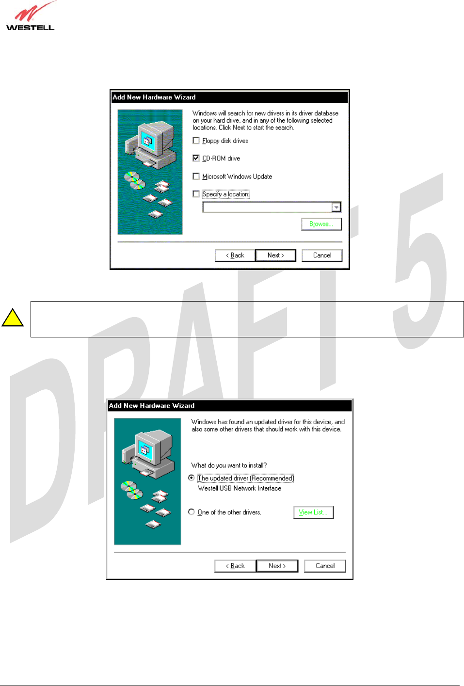
3. Windows 98 SE: Select CD-ROM drive (Figure 6). Click Next. Windows will search for the driver.
Figure 6. Windows 98 SE
Note: If Figure 6 does not appear at this step, and Figure 7 appears with the text ‘USB Composite device’,
‘C:\Windows\Inf\USB.Inf’, do not continue. Click Back to Step 3 and specify the location of the Westell
CD-ROM.
4. Windows 98 SE: Select The updated driver (Recommended) Westell USB Network Interface (Figure 7).
Click Next.
Figure 7. Windows 98 SE
!
TriLink Gateway – Draft 5
030-300445 Rev. A
6/22/05
030-300445 Rev. A 21 June 2005
User Guide TriLink Gateway (Models 427V10, 427V11)
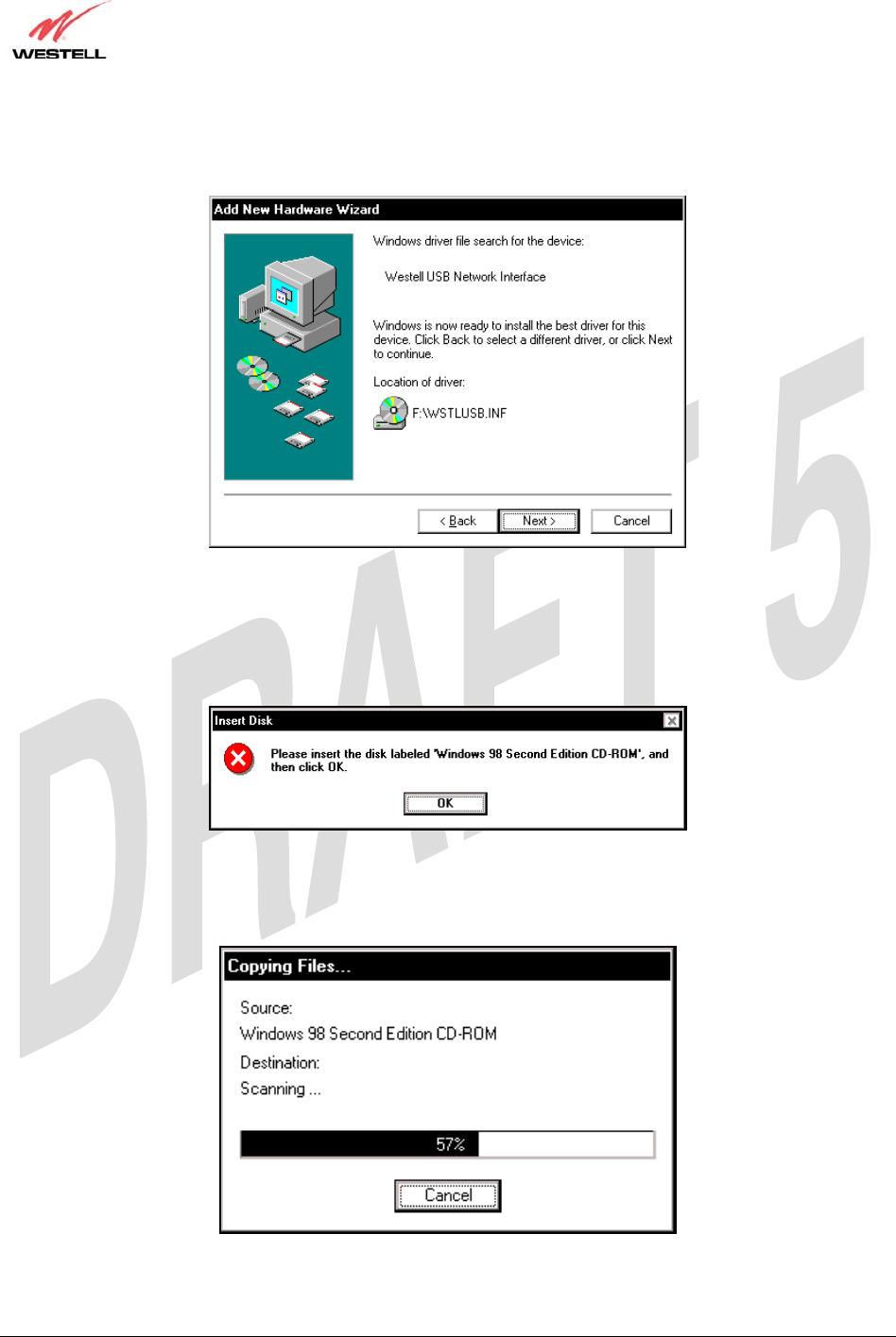
5. Windows 98 SE: Windows will display the location of the driver (Figure 8). The drive “letter” may vary. Click
Next.
Figure 8. Windows 98 SE
6. Windows 98 SE: Remove the Westell CD from the CD-ROM Drive. Next, insert the Windows operating system
CD into the CD-ROM Drive (Figure 9). Click OK.
Figure 9. Windows 98 SE
7. Windows 98 SE: The system will begin copying files (Figure 10).
Figure 10. Windows 98 SE
TriLink Gateway – Draft 5
030-300445 Rev. A
6/22/05
030-300445 Rev. A 22 June 2005
User Guide TriLink Gateway (Models 427V10, 427V11)
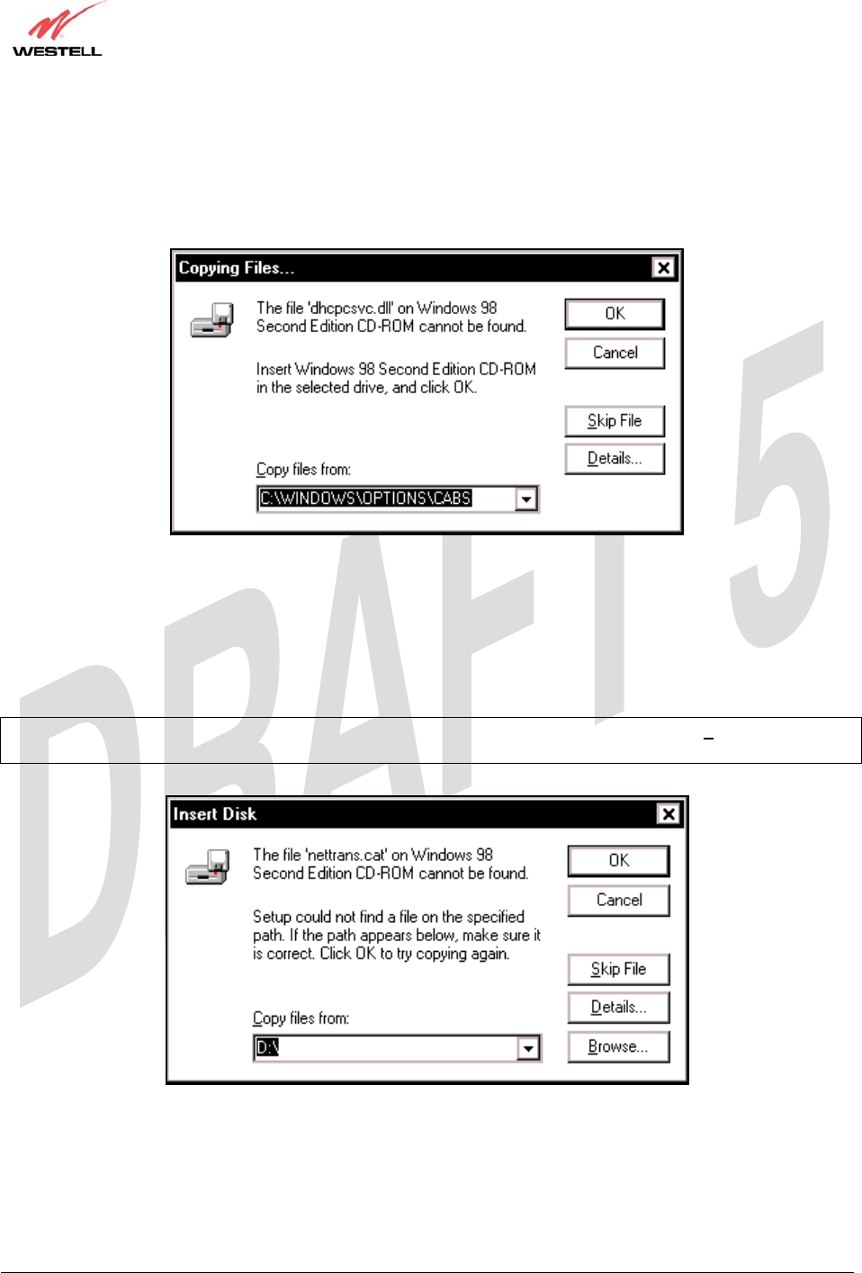
8. Windows 98 SE: Figure 11 may pop up, depending on how Windows 98 SE was installed on the computer. The
installation of the Westell Gateway requires files that are supplied by Microsoft for Windows 98 SE. If Figure 12
pops up, insert the Windows 98 SE Operating System CD into the computers CD-ROM drive, wait a moment for
the CD to be recognized by the system, and then click on OK. The system should find the required files on the
Windows 98 SE CD-ROM and automatically complete the installation.
Figure 11. Windows 98 SE
If the Operating System CD is not available, or if Figure 11 pops up again, you will have to manually specify the
location of the files. The required files may be stored on your hard drive. A common location for these files is
"C:\Windows\Options\Cabs." Try specifying this path or the path to your CD-ROM drive (usually "D:\") by clicking
the Browse… button in the Insert Disk screen (Figure 12). When you have specified the correct path, click on OK.
The system will begin copying the files.
NOTE: It is very important that the Windows 98 SE files be installed. Do not click on Cancel or Skip File in the
dialogs, doing so will result in an improper installation and the Gateway will not function correctly.
Figure 12. Windows 98 SE
TriLink Gateway – Draft 5
030-300445 Rev. A
6/22/05
030-300445 Rev. A 23 June 2005
User Guide TriLink Gateway (Models 427V10, 427V11)
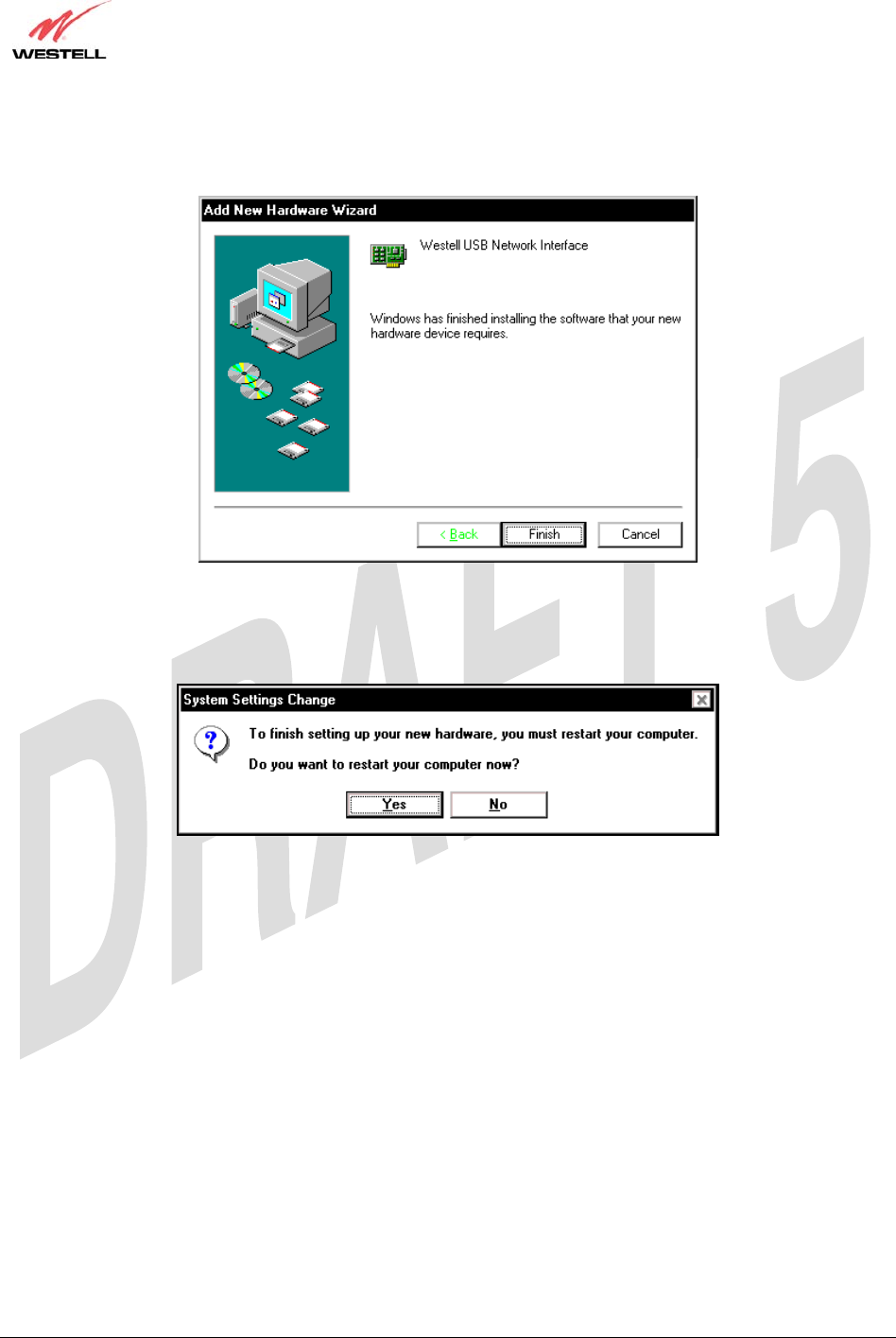
9. Windows 98 SE: The window below confirms that the PC has finished loading the drivers (Figure 13). Click
Finish.
Figure 13. Windows 98 SE
10. Windows 98 SE: Click Yes to restart your computer (Figure 14).
Figure 14. Windows 98 SE
Congratulations! You have completed the software installation for the USB drivers. After the computer has restarted,
your Router is ready for use. You must now return to section 6.4.4, “Connecting PCs via USB,” to complete the
hardware installation instructions.
TriLink Gateway – Draft 5
030-300445 Rev. A
6/22/05
030-300445 Rev. A 24 June 2005
User Guide TriLink Gateway (Models 427V10, 427V11)
7.2 Installing the USB Drivers for Windows ME
IMPORTANT: Confirm that the CD-ROM provided with the kit is inserted in the appropriate drive
before continuing this installation.
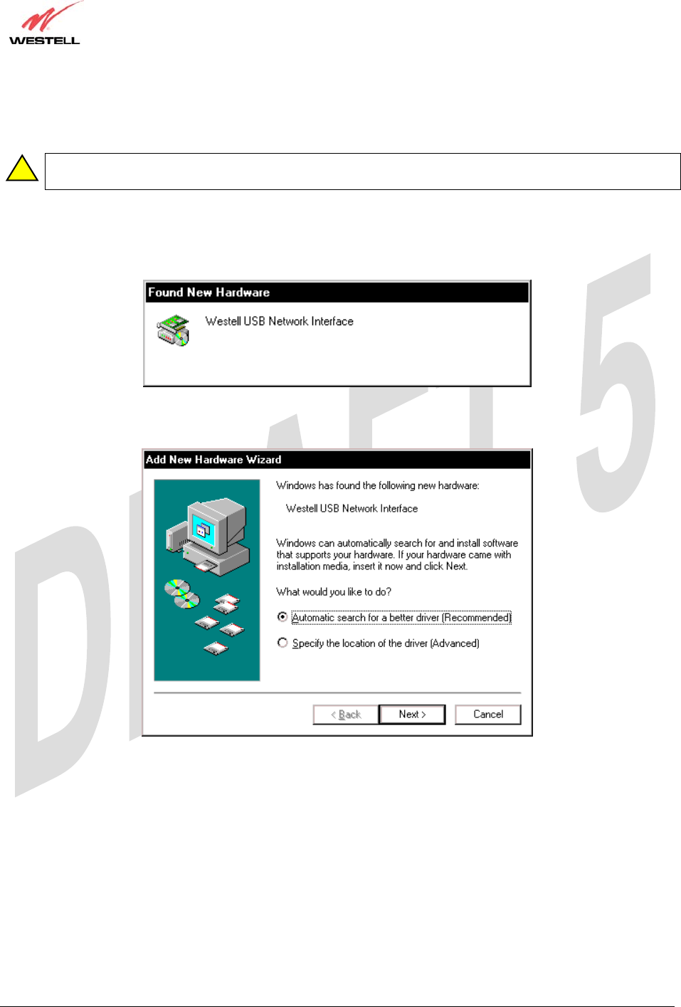
1. Windows ME: After you connect the Router to your PC, the Found New Hardware window will appear
(Figure 15). After a brief delay, the Add New Hardware Wizard will appear (Figure 16). Select Automatic
search for a better driver (Recommended). Click Next.
Figure 15. Windows ME
Figure 16. Windows ME
!
TriLink Gateway – Draft 5
030-300445 Rev. A
6/22/05
030-300445 Rev. A 25 June 2005
User Guide TriLink Gateway (Models 427V10, 427V11)
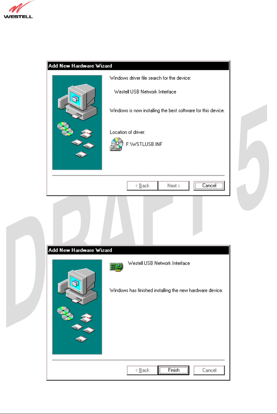
2. Windows ME: Windows will display the location of the driver (Figure 17). Click Next.
Figure 17. Windows ME
3. Windows ME: The window below confirms that the PC has finished loading the drivers (Figure 18). Click
Finish.
Figure 18. Windows ME
TriLink Gateway – Draft 5
030-300445 Rev. A
6/22/05
030-300445 Rev. A 26 June 2005
User Guide TriLink Gateway (Models 427V10, 427V11)
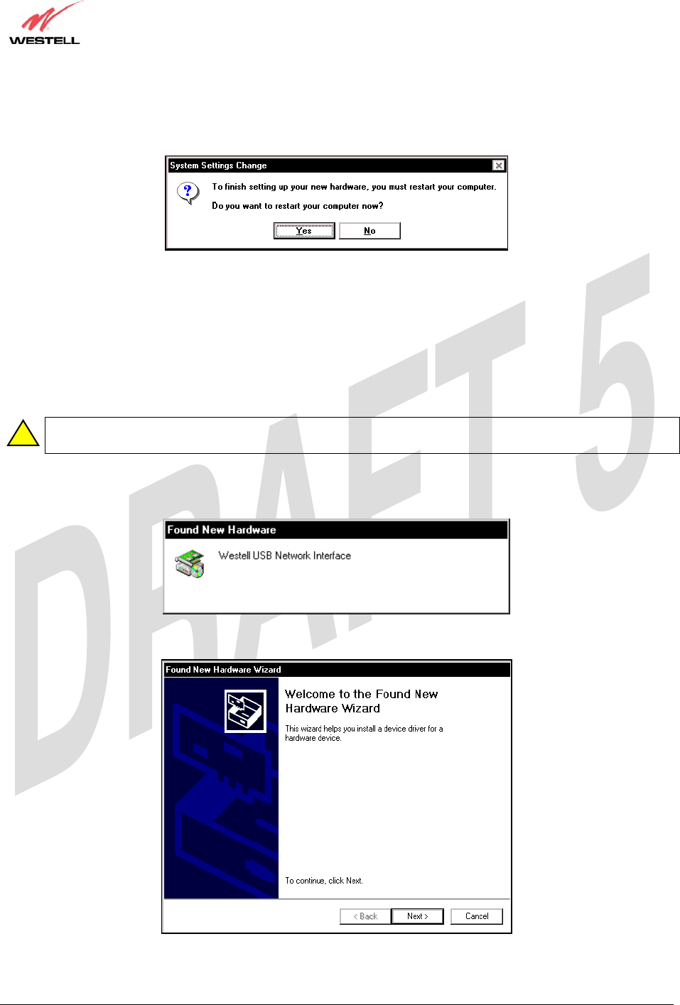
4. Windows ME: When the System Settings Change screen appears, the USB drivers are installed properly
(Figure 19). Click Yes.
Figure 19. Windows ME
Congratulations! You have completed the software installation for the USB drivers. After the computer has restarted,
the Router is ready for use. You must now return to section 6.4.4, “Connecting PCs via USB,” to complete the
hardware installation instructions.
7.3 Installing the USB Driver for Windows 2000
IMPORTANT: Confirm that the CD-ROM provided with the kit is inserted in the appropriate drive
before continuing this installation.
1. Windows 2000: After you connect the Router to your PC, the Found New Hardware window will appear
(Figure 20). After a brief delay, the Found New Hardware Wizard will appear (Figure 21). Click Next.
Figure 20. Windows 2000
Figure 21. Windows 2000
!
TriLink Gateway – Draft 5
030-300445 Rev. A
6/22/05
030-300445 Rev. A 27 June 2005
User Guide TriLink Gateway (Models 427V10, 427V11)
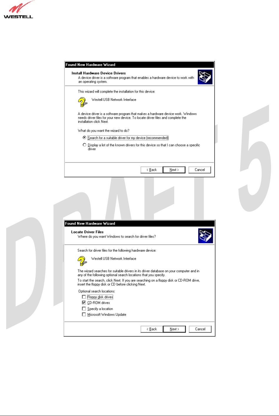
2. Windows 2000: The Install Hardware Device Drivers window appears. Select Search for a suitable driver
for my device (recommended). See Figure 22. Click Next.
Figure 22. Windows 2000
3. Windows 2000: The Locate Driver Files window appears. Select CD-ROM drives (Figure 23). Click Next.
Figure 23. Windows 2000
TriLink Gateway – Draft 5
030-300445 Rev. A
6/22/05
030-300445 Rev. A 28 June 2005
User Guide TriLink Gateway (Models 427V10, 427V11)
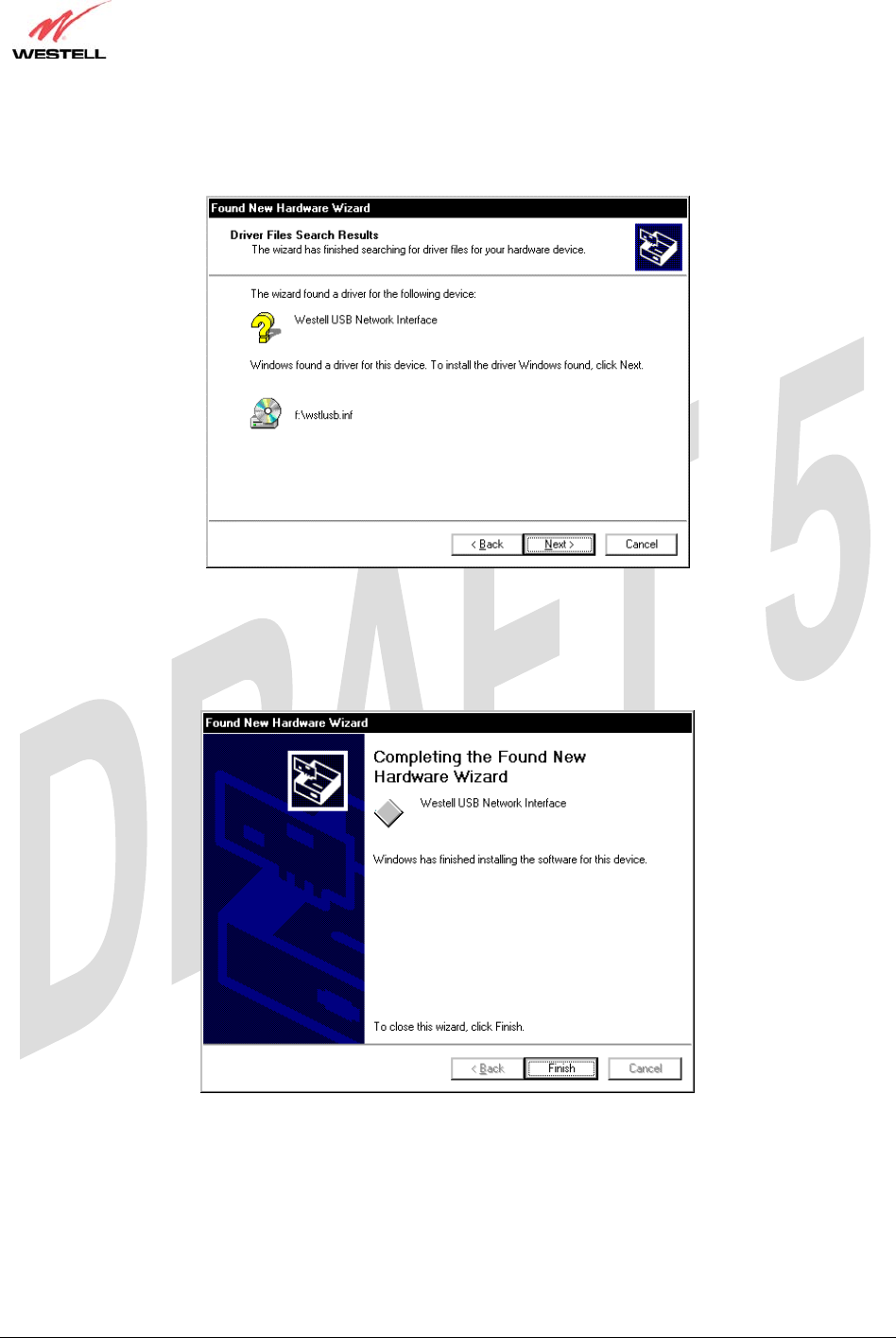
4. Windows 2000: The Driver Files Search Results window appears (Figure 24). Note: The drive “letter” may
vary. Click Next.
Figure 24. Windows 2000
5. Windows 2000: The window below confirms that the PC has finished loading the drivers (Figure 25). Click
Finish.
Figure 25. Windows 2000
TriLink Gateway – Draft 5
030-300445 Rev. A
6/22/05
030-300445 Rev. A 29 June 2005
User Guide TriLink Gateway (Models 427V10, 427V11)
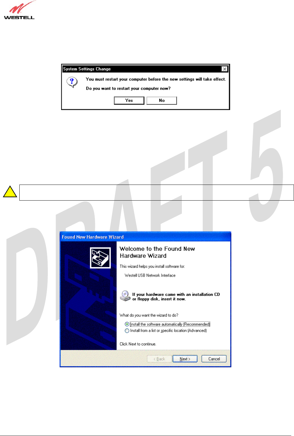
6. Windows 2000: When the System Settings Change screen appears, the USB drivers are installed properly
(Figure 26). Click Yes.
Figure 26. Windows 2000
Congratulations! You have completed the software installation for the USB drivers. After the computer has restarted,
VersaLink is ready for use. You must now return to section 6.4.4, “Connecting PCs via USB,” to complete the
hardware installation instructions.
7.4 Installing the USB Driver for Windows XP
IMPORTANT: Confirm that the CD-ROM provided with the kit is inserted in the appropriate drive
before continuing this installation.
1. Windows XP: After you connect the Router to your PC, the following screen will appear. (Figure 27). Select
Install the software automatically (Recommended). Click Next.
Figure 27. Windows XP
!
TriLink Gateway – Draft 5
030-300445 Rev. A
6/22/05
030-300445 Rev. A 30 June 2005
User Guide TriLink Gateway (Models 427V10, 427V11)
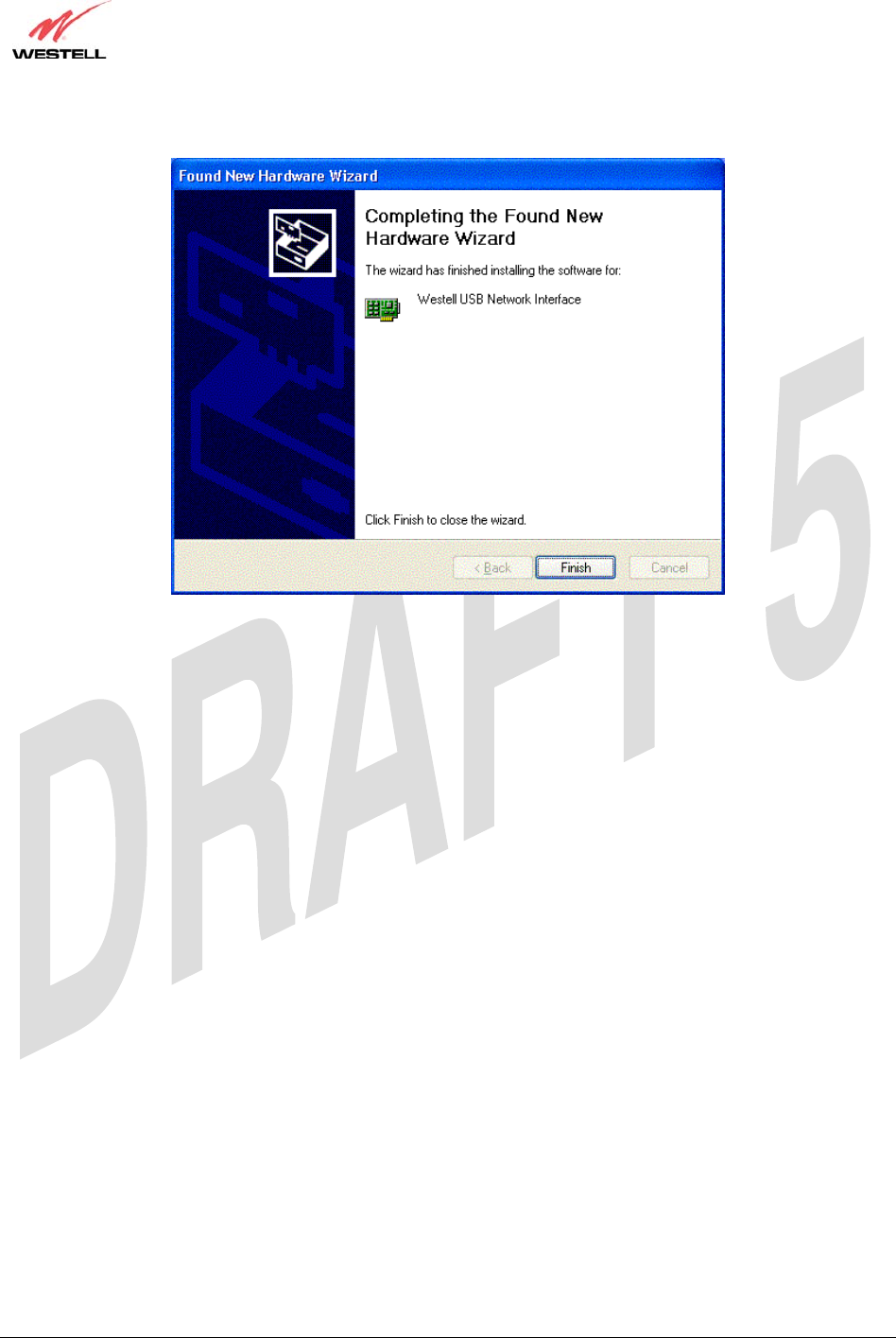
2. Windows XP: The window below confirms that the PC has finished loading the drivers (Figure 28). Click Finish.
Figure 28. Windows XP
Congratulations! You have completed the software installation for the USB drivers. After the computer has restarted,
your Router is ready for use. You must now return to section 6.4.4, “Connecting PCs via USB,” to complete the
hardware installation instructions.
TriLink Gateway – Draft 5
030-300445 Rev. A
6/22/05
030-300445 Rev. A 31 June 2005
User Guide TriLink Gateway (Models 427V10, 427V11)
8. CONFIGURING THE ROUTER FOR INTERNET CONNECTION
To browse the Internet using your TriLink™ Gateway, you must confirm your DSL sync, set up your account
profile, and establish a PPP session with your Internet service provider (ISP).
NOTE: Internet service provider subscriber software and connection requirements may vary. Refer to the Internet
service provider’s installation manual to install the software required for your Internet connection.
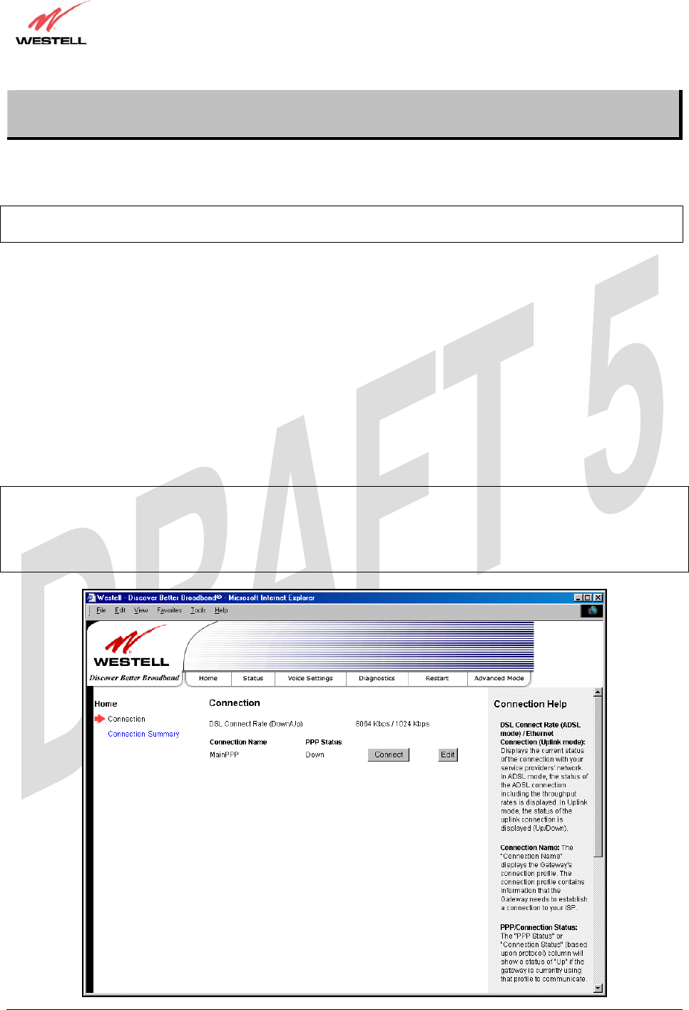
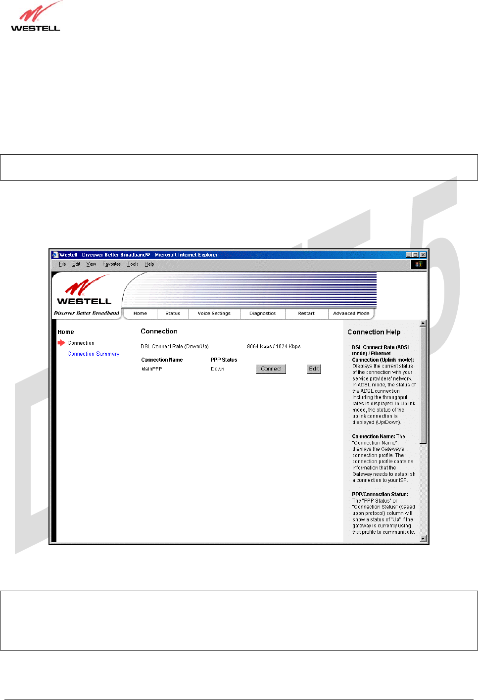
8.1 Confirming a DSL Sync
After connecting the hardware for your TriLink™ Gateway, bring up your Web browser. Type http://192.168.1.1/ in
the browser’s address window and press ‘Enter’ on your keyboard. The following Connection Overview screen will
be displayed.
You must have active DSL service before the Gateway can synchronize with your ISP’s equipment. To determine if the
Router has a DSL sync, view the DSL Connection Rate at the Connection Overview field. If the status reads No DSL
Connection, check the DSL physical connection, explained in section 6 (INSTALLING THE HARDWARE) of this
User Guide. The following screen shows the DSL connection rate with values that indicate a successful DSL SYNC has
been established. The connection rate values represent the transmission speed of your DSL line. (The Gateway may take
time to report these values.)
NOTE: If no DSL sync is established, the Connection button will not be displayed in the Connection Overview
screen. To determine if the DSL sync is established, check the Gateway’s DSL LED. If the DSL LED is not solid
green, you do not have a DSL sync established. Contact your Internet service provider for further instructions. The
Gateway will handle transmission rates up to 8 Mbps. Your actual DSL rates may vary depending on your Internet
service provider.

TriLink Gateway – Draft 5
030-300445 Rev. A
6/22/05
030-300445 Rev. A 32 June 2005
User Guide TriLink Gateway (Models 427V10, 427V11)
Connection Overview Displays your DSL connection rate.
Connection Name The name of the connection profile you are using.
PPP Status UP = PPP session established
DOWN = No PPP session established.
Connect/Disconnect Click Connect to establish a PPP session.
Click Disconnect to disconnect a PPP session
Edit Click Edit to edit the connection profile.
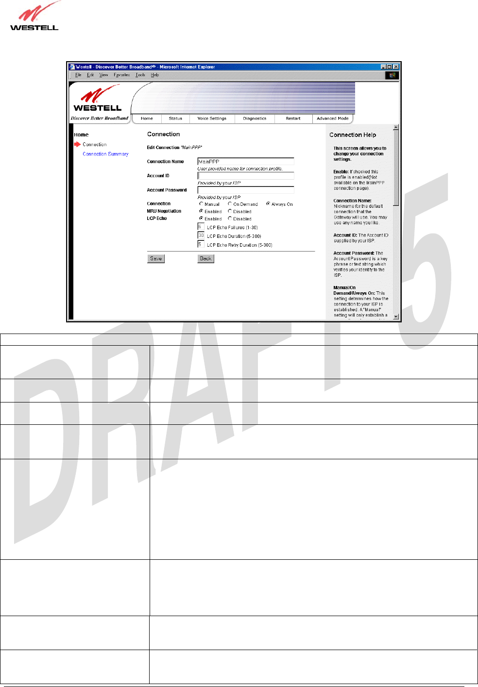
8.2 Setting Up a Connection Profile
After you have confirmed your DSL sync, click Edit in the Connection Overview screen to set up your connection
profile. The following Edit Connection screen will be displayed. This screen enables you to add new connection
profiles or to edit existing connection profiles. Connection profiles can be associated with specific service settings,
such as connection settings or NAT services, enabling you to customize your Router for specific users. The
Connection Name field enables you to enter the desired name that you wish to use for each profile that you set up.
You may create and store up to eight unique connection profiles in your Router, which you can use once you
establish a PPP session with your ISP.
Important: Before you set up a connection profile, you must obtain your Account ID, Account Password, and
VPI/VCI values from your Internet service provider. You will use information when you set up your account
parameters. If you are at a screen and need help, refer to the Help section located at the right of the screen.
Profile Parameters include:
● Connection Name-the Connection Name is a word or phrase that you use to identify your account.
(You may enter up 64 characters in this field.)
● Account ID-the Account ID is provided by your Internet Service Provider.
(You may enter up 255 characters in this field.)
● Account Password-the Account Password is provided by your Internet Service Provider.
(You may enter up 255 characters in this field.)
TriLink Gateway – Draft 5
030-300445 Rev. A
6/22/05
030-300445 Rev. A 33 June 2005
User Guide TriLink Gateway (Models 427V10, 427V11)
Connection
Edit Connection Factory Default = MainPPP
The name of the default connection profile. Westell recommends that you use the
Default parameter.
Connection Name This field allows you to enter a new connection name of your choice (up to 64
characters).
Account ID The account ID (provided by your Internet service provider ). If you have
multiple Service Providers, you can enter this information at this time.
Account Password The account password that you are using to connect to your Internet service
provider (provided by your Internet service provider ). If you have multiple
Service Providers, you can enter this information at this time.
Connection Factory default = Always On
Manual: Selecting this feature allows you to manually establish your PPP
session.
On Demand: Selecting this feature allows the Router to automatically re-
establish your PPP session on demand anytime your PC requests Internet activity
(for example, browsing the Internet, email, etc.). When you have traffic, it may
cause a delay.
Always On: Selecting this feature allows the Router to automatically establish a
PPP session when you log on or if the PPP session goes down.
MRU Negotiation Factory Default = Enabled
When Enabled, the Maximum Received Unit (MRU) will enforce MRU
negotiations. (NOTE: Enable this option only at your Internet Service Provider’s
request.)
If Disabled, this function will not be activated.
LCP Echo Factory Default = Enable
If ‘Disabled’ is selected, this option will disable the modem LCP Echo
transmissions.
LCP Echo Failures Factory Default = 6
Indicates number of continuous LCP echo non-responses received before the PPP
session is terminated. This value must be between 1 and 30 inclusive.
TriLink Gateway – Draft 5
030-300445 Rev. A
6/22/05
030-300445 Rev. A 34 June 2005
User Guide TriLink Gateway (Models 427V10, 427V11)
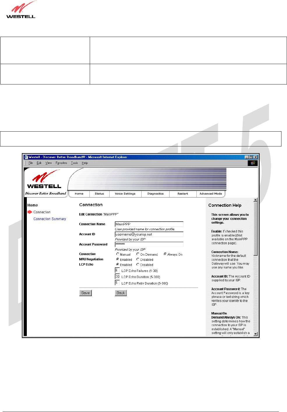
LCP Echo Duration Factory Default = 30
The interval between LCP Echo transmissions with responses. This value must
be between 5 and 300 seconds inclusive and greater than or equal to the Retry
Duration.
LCP Echo Retry Duration Factory Default = 5
The interval between LCP. Echo after no response.
This value must be between 5 and 300 seconds inclusive.
At the Edit Connection screen, type your Connection Name, Account ID and Account Password (the Account
Password will be masked for security), and then select the default Service Profile setting that you will use for this
connection profile. The factory default connection setting for the “Default” Service Profile is set to Always on. Click
Back if you do not want to add or edit a connection profile. Click Save to save the connection profile.
NOTE: If you click Back before you click Save, the previously saved settings will remain active, and any recent
changes that you have made to this screen will not take effect. You must click Save to save the settings.
TriLink Gateway – Draft 5
030-300445 Rev. A
6/22/05
030-300445 Rev. A 35 June 2005
User Guide TriLink Gateway (Models 427V10, 427V11)
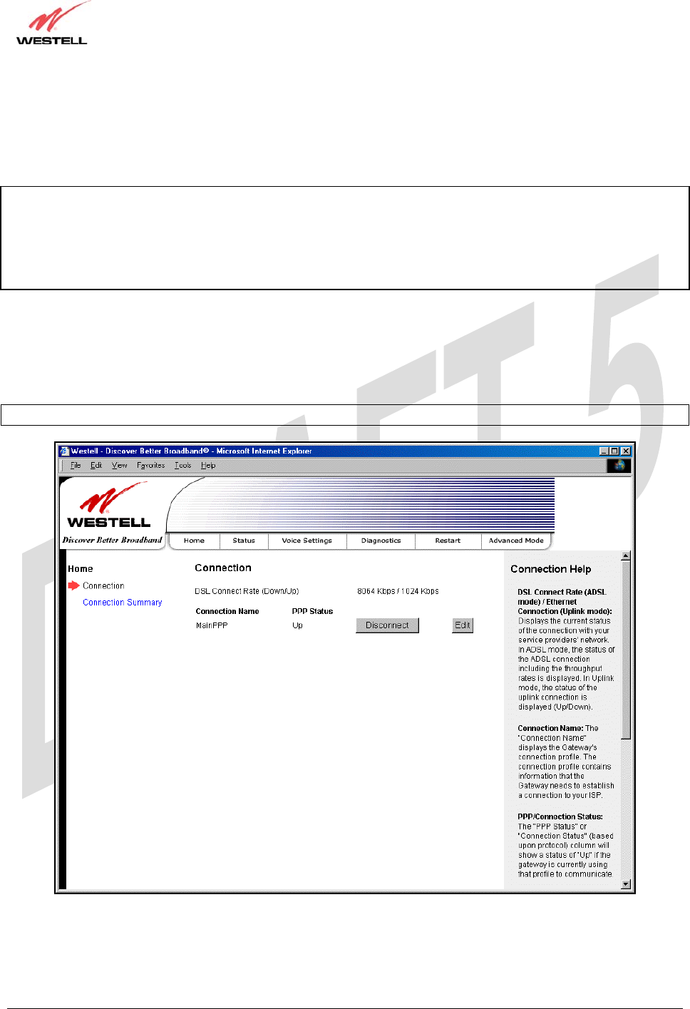
8.3 Establishing a PPP Session
After you have set up your connection profile and clicked Save, view the PPP Status field at the Connection
Overview screen. If the PPP Status displays DOWN, click the Connect button to establish a PPP session.
NOTE: Whenever the PPP Status displays DOWN, you do not have a PPP session established. If your Router’s
Service Profile setting is set to “Always On” or “On Demand,” after a brief delay, the PPP session will be established
automatically and the PPP Status will display UP. If the connection setting is set to “Manual,” you must click on the
Connect button to establish a PPP session. Once the PPP session has been established (PPP Status displays UP), you
may proceed with your Router’s configuration. Refer to the preceding Edit Connection screen to change your
Service Profile setting.) The factory default Service Profile setting is “Always on.”
The following screen displays Up in the PPP Status field. This indicates that Connection1 is the active account
profile and that you have established a PPP session with your Internet service provider (ISP). If you have set up
multiple account profiles (for example, Connection2, Connection3, etc.) they will also be displayed in the
Connection Name field, and then you must select the option button adjacent to the connection name you want to
use. Refer to section 8.2 for details on setting up a connection profile.
NOTE: If you experience problems establishing a PPP session, contact your ISP for further instructions.
TriLink Gateway – Draft 5
030-300445 Rev. A
6/22/05
030-300445 Rev. A 36 June 2005
User Guide TriLink Gateway (Models 427V10, 427V11)
After a PPP session has been established, you may browse the Internet. For example, to visit Westell’s home page,
type http://www.westell.com in your browser’s address window and then press ‘Enter’ on your keyboard.
When you are ready to return to the Router’s interface, type http://192.168.1.1 in your browser’s address window,
and then press ‘Enter’ on your keyboard.
TriLink Gateway – Draft 5
030-300445 Rev. A
6/22/05
030-300445 Rev. A 37 June 2005
User Guide TriLink Gateway (Models 427V10, 427V11)
8.4 Disconnecting a PPP Session
If you have finished browsing the Internet and want to disconnect from your Internet service provider, click the
Disconnect button in the Connection Overview screen. The following pop-up screen will appear. Click OK to
disconnect the PPP session.
Warning: If you disconnect the PPP session, this will disconnect the Router from the Internet, and all users will be
disconnected until the PPP session is re-established.
If you clicked the Disconnect button in the Connection Overview screen, the PPP Status should display DOWN.
This means that you no longer have a PPP session (no IP connection to your Internet service provider); however,
your DSL session will not be affected. When you are ready to end your DSL session, simply power down the Router
via the power switch on the Router’s rear panel.
When you are ready to establish a PPP session, click the Connect button. (If you powered down the Router, you
must first power up the Router, and then log on to your account profile before you establish a PPP session.)
NOTE: When you are ready to exit the Router’s interface, click the X (close) in the upper-right corner of the screen.
Closing the window will not affect your PPP Status (your PPP session will not be disconnected). You must click on
the disconnect button to disconnect your PPP session. When you are ready to restore this interface, you must launch
your Internet browser and type http://dslrouter/ or type http://192.168.1.1/ in the browser’s address window and
press ‘Enter’ on your keyboard.
TriLink Gateway – Draft 5
030-300445 Rev. A
6/22/05
030-300445 Rev. A 38 June 2005
User Guide TriLink Gateway (Models 427V10, 427V11)
9. SETTING UP MACINTOSH OS X
This section provides instructions on how to use Macintosh Operating System 10 with the Router. Follow the
instructions in this section to create a new network configuration for Macintosh OS X.
NOTE: Macintosh computers must use the Modem Ethernet installation. Refer to section 6 (INSTALLING
THE HARDWARE).
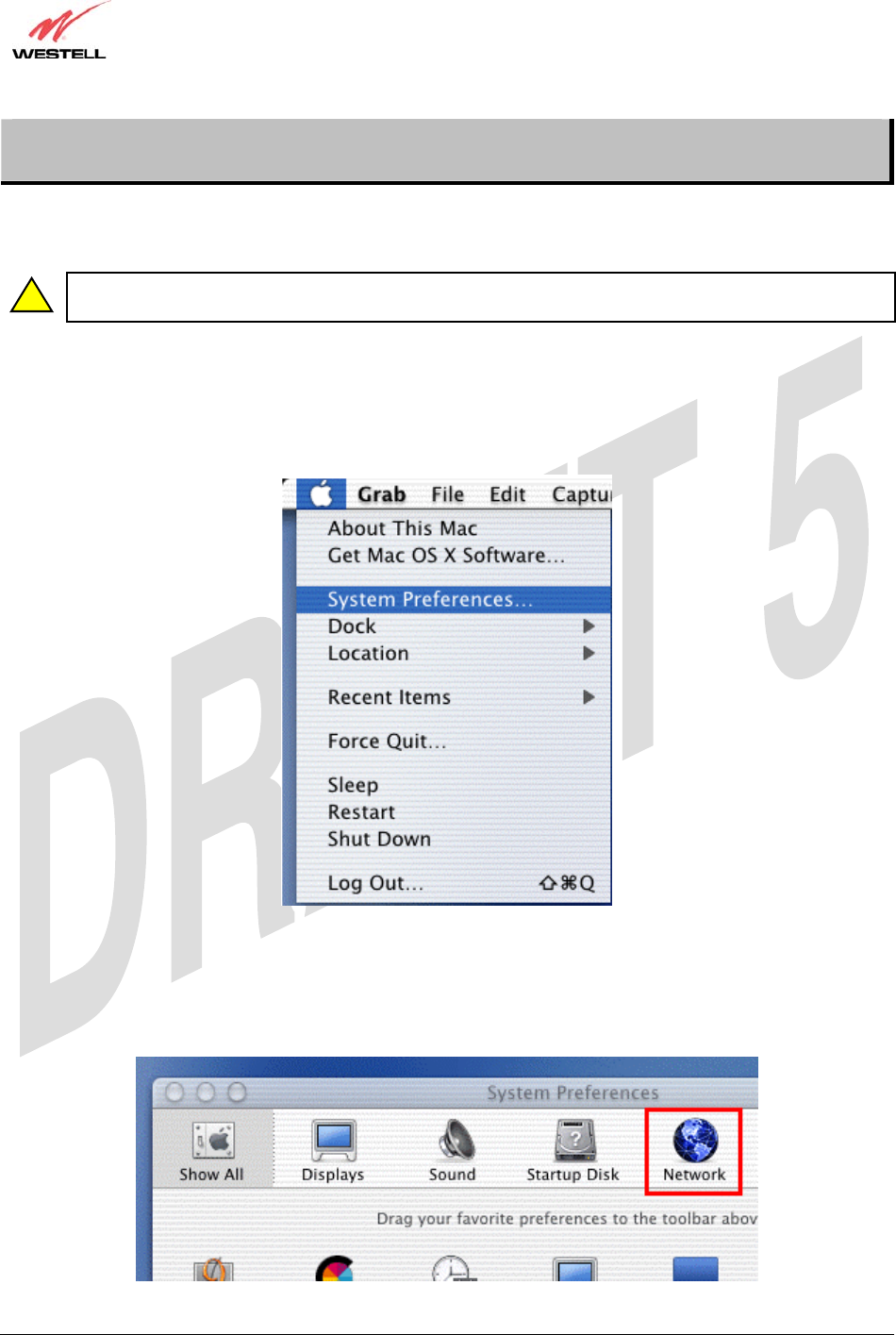
Open the System Preference Screen
After you have connected the Westell Router to the Ethernet port of your Macintosh, the screen below will appear.
Click on the “Apple” icon in the upper-right corner of the screen and select System Preferences.
Choose the Network Preferences
After selecting System Preferences…, from the previous screen, the System Preferences screen will be displayed.
From the System Preferences screen, click on the Network icon.
!
TriLink Gateway – Draft 5
030-300445 Rev. A
6/22/05
030-300445 Rev. A 39 June 2005
User Guide TriLink Gateway (Models 427V10, 427V11)
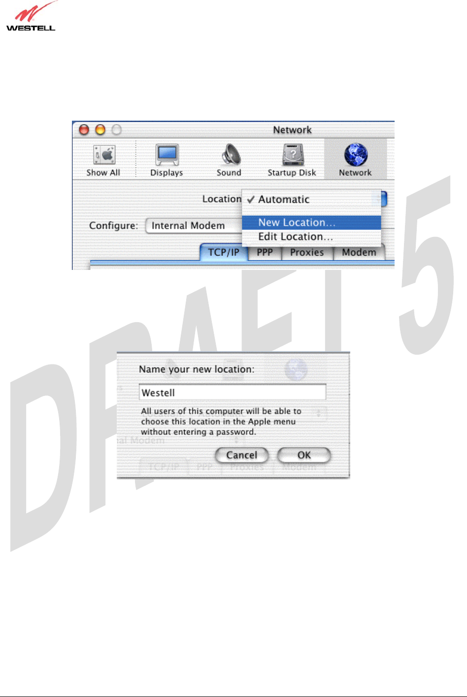
Create a New Location
After selecting the Network icon at the System Preferences screen, the Network screen will be displayed. Select
New Location from the Location field.
Name the New Location
After selecting New Location from the Network screen, the following screen will be displayed. In the field labeled
Name your new location:, change the text from “Untitled” to “Westell.” Click OK.
TriLink Gateway – Draft 5
030-300445 Rev. A
6/22/05
030-300445 Rev. A 40 June 2005
User Guide TriLink Gateway (Models 427V10, 427V11)
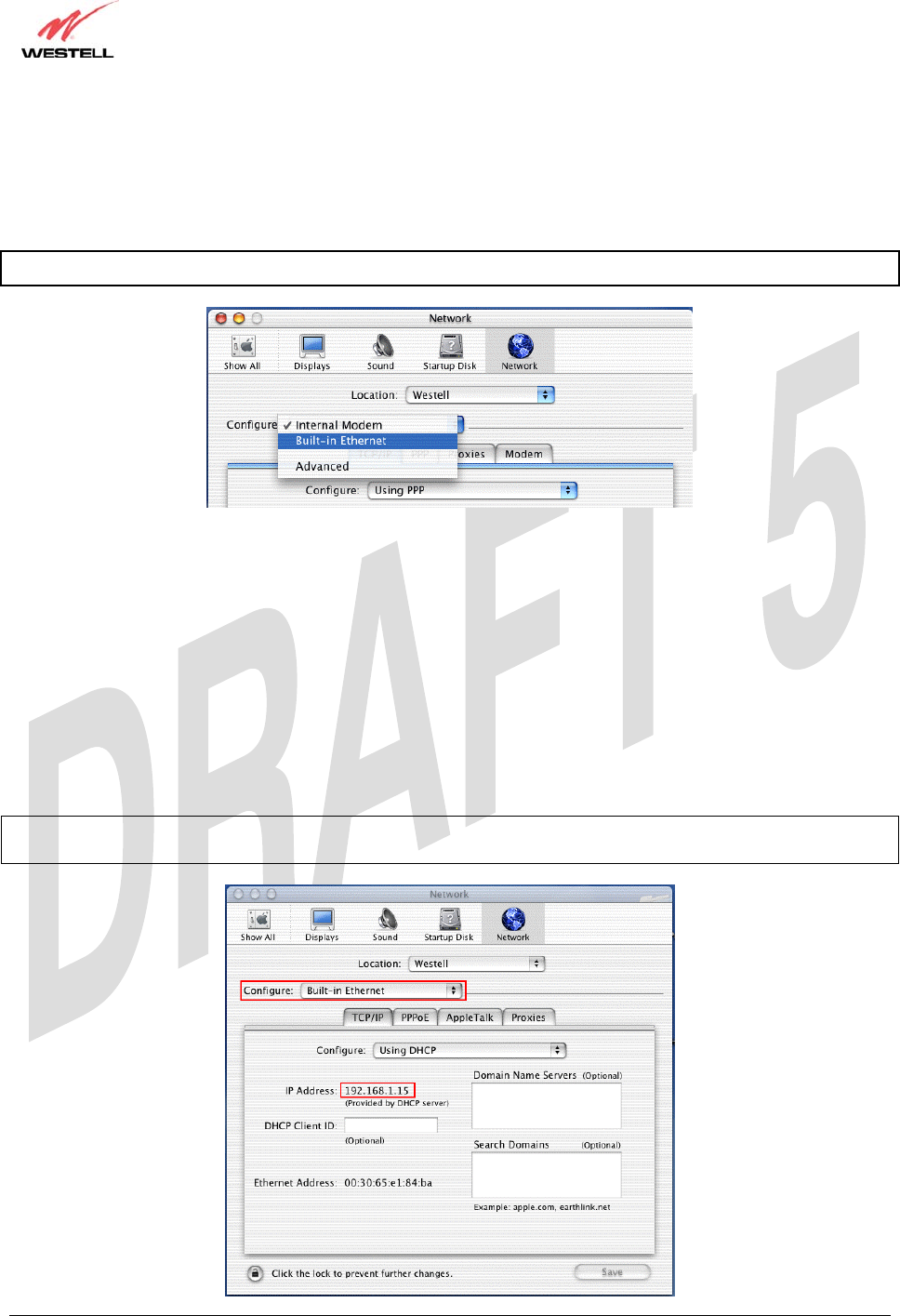
Select the Ethernet Configuration
After clicking on OK in the preceding screen, the Network screen will be displayed. The Network screen shows the
settings for the newly created location. From the Configure field in the Network screen, select Built-in Ethernet.
Click on Save.
NOTE: Default settings for the Built-in Ethernet configuration are sufficient to operate the Router.
Check the IP Connection
To verify that the computer is communicating with the Router, follow the instructions below.
1. Go to the “Apple” icon in the upper-right corner of the screen and select System Preferences.
2. From the System Preferences screen, click on the Network icon. The Network screen will be displayed.
3. From the Configure field in the Network screen, select Built-in Ethernet.
4. View the IP address field. An IP address that begins with 192.168.1 should be displayed.
NOTE: The DHCP server provides this IP address. If this IP address is not displayed, check the Router’s wiring
connection to the PC. If necessary, refer to section 5 for hardware installation instructions.
TriLink Gateway – Draft 5
030-300445 Rev. A
6/22/05
030-300445 Rev. A 41 June 2005
User Guide TriLink Gateway (Models 427V10, 427V11)
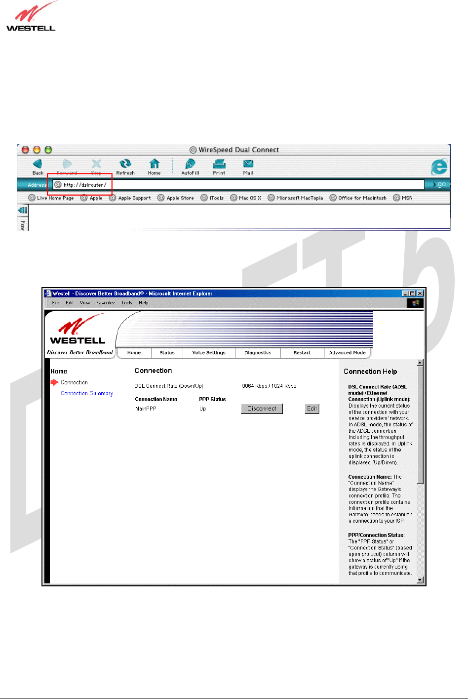
Create a User Account
In the address window of your Internet Explorer web browser, type http://dslrouter/, and then press ‘Enter’ on your
keyboard.
The Connection Overview screen will be displayed. You may now begin your Account Setup. Refer to section 8 of
this User Guide to configure your Westell Router for Internet connection.
TriLink Gateway – Draft 5
030-300445 Rev. A
6/22/05
030-300445 Rev. A 42 June 2005
User Guide TriLink Gateway (Models 427V10, 427V11)
10. BASIC MODE
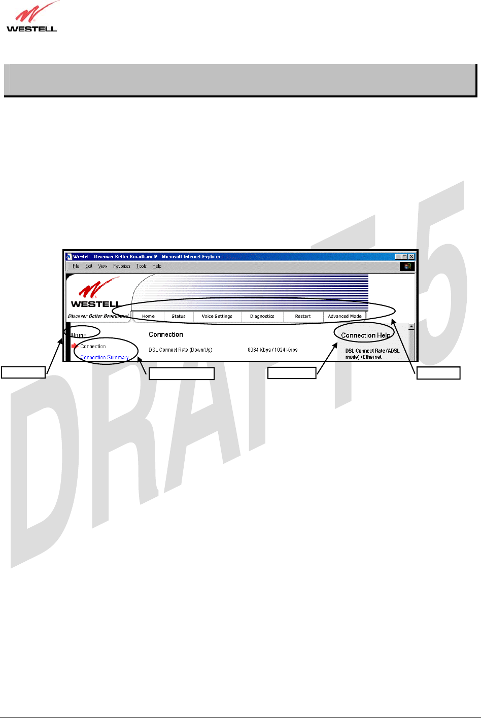
The following sections explain the basic configurations of your Router. The Router’s web pages contain a main
navigation menu, displayed at the top of the screens. As you navigate through the various pages of the Router, the
active page that you have selected from the Main menu will appear in the left corner of the screen. The submenu
options for that page will appear in the left-side navigation menu, as shown below. A red arrow will be displayed
adjacent to the active submenu option. Please note that the values displayed in the screens might differ from the
actual values reported by your Router. If you are at a screen and need help, refer to the Help section, displayed on the
right side of the screen. Additional details are displayed in the tables below the screens.
Some screens require that you save your settings. To save your settings, click the Save button. To discard changes
that you have made to the screen, click the Discard button. If you click the Discard button, the previously saved
settings will be displayed in the screen.
Main Menu
Help Section
Active Page Submenu Options
TriLink Gateway – Draft 5
030-300445 Rev. A
6/22/05
030-300445 Rev. A 43 June 2005
User Guide TriLink Gateway (Models 427V10, 427V11)
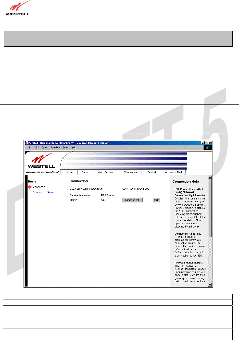
11. HOME
11.1 Connection
After you have set up your account profile and established your PPP session, as discussed earlier in section 8, you are
ready to select a menu option from the main navigation menu. If you select Home at the main menu, the following
Connection Overview screen will be displayed. As explained earlier in section 8, the Connection Overview screen
enables you to view your DSL connection status, set up account profiles (via the Edit button), and establish your PPP
session. Refer to section 8 for details on the Connection Overview screen.
NOTE: The following screen displays Connection1 as the active connection profile. However, if you have created
multiple connection profiles (for example, Connection2, Connection3, etc.) they will also be displayed in the
Connection Name field, and then you must click the option button adjacent to the connection name you want to use.
Refer to section 8.2 for details on setting up a connection profile. You may store up to eight unique connection
profiles in your Router.
Connection Overview Displays your DSL connection rate.
Connection Name The Connection Name is from the connection profile that you set up in section 8.
PPP Status UP = PPP session established
DOWN = No PPP session established.
Connect/Disconnect Click Connect to establish a PPP session.
Click Disconnect to disconnect a PPP session
Edit Click Edit to edit or add a connection profile. Refer to section 7 for details on
connections profiles.
TriLink Gateway – Draft 5
030-300445 Rev. A
6/22/05
030-300445 Rev. A 44 June 2005
User Guide TriLink Gateway (Models 427V10, 427V11)
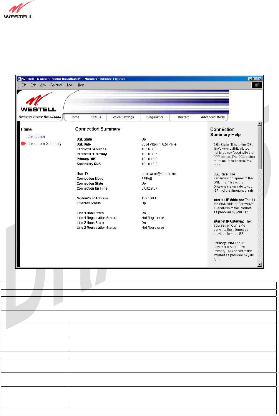
11.2 Connection Summary
If you select Connection Summary at the Home menu the following screen will be displayed. Refer to this screen
for information about your Router’s connections.
DSL State The DSL’s connectivity status.
DSL Rate The transmission speed of your DSL line.
Internet IP Address The WAN side or Gateway’s IP address to the Internet. Provided by your Internet
service provider.
Internet IP Gateway The IP address of your ISP’s server to the Internet. Provided by your Internet service
provider.
Primary DNS The IP address of your ISP’s primary DNS server. Provided by your Internet service
provider.
Secondary DNS The IP address of your ISP’s secondary DNS server. Provided by your Internet
service provider.
User ID The same as your Account ID. Provided by your Internet service provider.
Connection Mode The Gateway’s mode of connection to your ISP. This can be PPPoE, PPPoA,
Bridge, or IP.
Connection State The Gateway’s PPP connectivity status to the Internet. The DSL status must be up in
order for the PPP connectivity to be up.
Connection Up Time The duration of your PPP time status. This time field tell how long the Gateway has
had a PPP connection established, displayed in the format of
(hours:minutes:seconds).
Modem’s IP Address The IP Address on the LAN side of your Gateway.

TriLink Gateway – Draft 5
030-300445 Rev. A
6/22/05
030-300445 Rev. A 45 June 2005
User Guide TriLink Gateway (Models 427V10, 427V11)
Ethernet Status The Gateway’s LAN-side Ethernet connection status. This is the Ethernet status
between the Gateway and your computer.
Line 1 Hook State This indicates the state of the line. “Onhook” means the line is not in use. “Offhook”
means the telephone receiver is either in use or the receiver is offhook for some
other reason.
Line 1 Registration Status Indicates whether the line has registered with the SIP proxy server.
Line 2 Hook State This indicates the state of the line. “Onhook” means the line is not in use. “Offhook”
means the telephone receiver is either in use or the receiver is offhook for some
other reason.
Line 2 Registration Status Indicates whether the line has registered with the SIP proxy server.
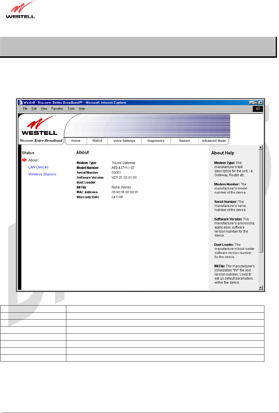
TriLink Gateway – Draft 5
030-300445 Rev. A
6/22/05
030-300445 Rev. A 46 June 2005
User Guide TriLink Gateway (Models 427V10, 427V11)
12. STATUS
12.1 About
The following screen will be displayed if you select About from the Status menu.
Modem Type The Router manufacturer’s modem name.
Model Number The Router manufacturer’s model number.
Serial Number The Router manufacturer’s serial number.
Software Version The version of the application software and the build date.
Boot Loader The manufacturer’s boot load number.
INI File The Router manufacturer’s INI information.
MAC Address Media Access Controller (MAC) i.e., hardware address of this device.
Warranty Date The start date of the Router’s warranty
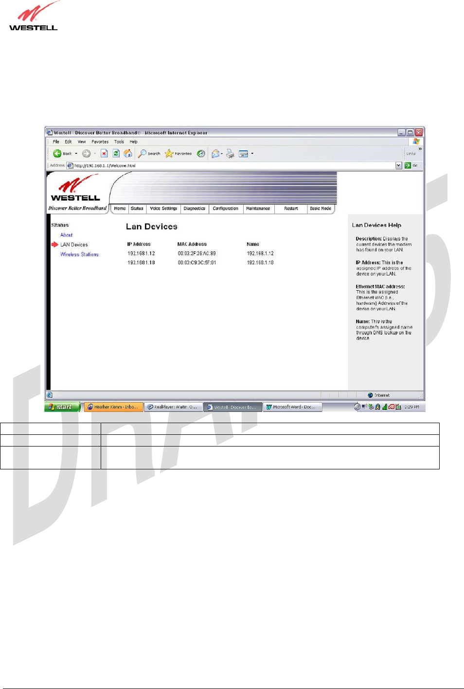
TriLink Gateway – Draft 5
030-300445 Rev. A
6/22/05
030-300445 Rev. A 47 June 2005
User Guide TriLink Gateway (Models 427V10, 427V11)
12.2 LAN Devices
The following screen will be displayed if you select LAN Devices from the Status menu. This screen displays all the
devices on the LAN.
IP Address The assigned IP address of the networking device.
MAC Address The assigned Ethernet MAC (i.e., hardware) address of the networking device.
Name The computer’s assigned name. Note: The computer name or the IP address may be
displayed in this field.
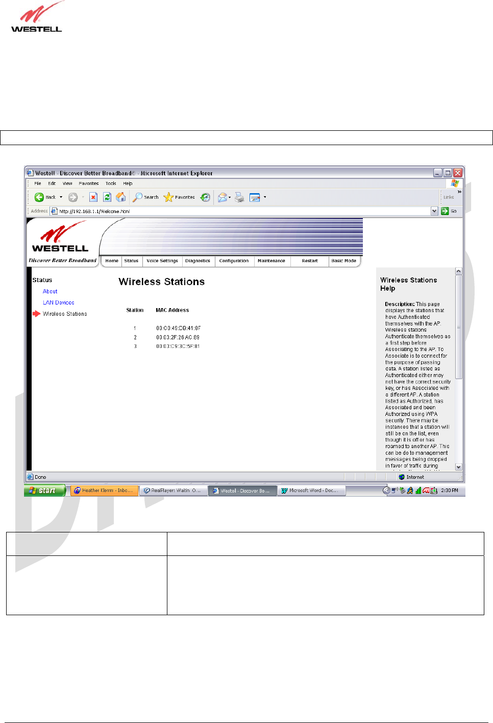
TriLink Gateway – Draft 5
030-300445 Rev. A
6/22/05
030-300445 Rev. A 48 June 2005
User Guide TriLink Gateway (Models 427V10, 427V11)
12.3 Wireless Stations
The following screen will be displayed if you select Wireless Stations from the Status menu. This page displays the
information about the wireless stations that are associated with the Router.
Note: The Station and MAC Address fields in this screen will be blank if no stations are associated with the AP.
Station A number indicating the order in which the stations first access the AP.
This list can contain a maximum of 10 stations.
MAC Address The Media Access Controller (MAC) address (i.e., the hardware address
of the associated station). This is a unique number entered into the WLAN
device’s permanent memory during production. A station’s MAC address
is typically printed on the card or can be viewed using the card’s
configuration utility.
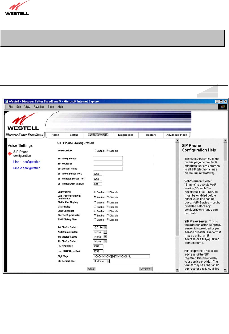
TriLink Gateway – Draft 5
030-300445 Rev. A
6/22/05
030-300445 Rev. A 49 June 2005
User Guide TriLink Gateway (Models 427V10, 427V11)
13. VOICE SETTINGS
13.1 SIP Phone Configuration
The following screen will be displayed if you select SIP Phone Configuration from the Voice Settings menu. If you
make changes to this screen, click Save to save your settings.
IMPORTANT: VoIP Service must be disabled in all screens before any configurations can be made to the screens.

TriLink Gateway – Draft 5
030-300445 Rev. A
6/22/05
030-300445 Rev. A 50 June 2005
User Guide TriLink Gateway (Models 427V10, 427V11)
SIP Phone Configuration
SIP Phone Configuration The configuration settings on this page control the VoIP attributes that are
common to all SIP telephone lines on the TriLink Gateway.
VoIP Service Factory Default = Disable
VoIP Service must be enabled before either voice line can be used. VoIP
Service must be disabled before any configuration changes can be made.
Possible Response:
Select Enable to activate VoIP service.
Select Disable to deactivate VoIP service.
SIP Proxy Server The address of the SIP proxy server. This address is provided by your
service provider. The format may be either an IP address or a fully
qualified domain name.
SIP Registrar The address of the SIP registration server. This is provided by your service
provider. The format may be either an IP address or a fully qualified
domain name.
SIP Domain Name The name used in the “To” and “From” addresses of the SIP messages
sent from the Router. This is provided by your Internet service provider.
SIP Proxy Server Port Factory Default =5060
The UDP port number that the gateway will use to talk to the SIP proxy
server. This is provided by your service provider.
SIP Register Server Port Factory Default =5060
The UDP port number that the gateway will use to talk to the SIP
registration server. This is provided by your service provider.
SIP Registration Interval Factory Default =300
The period of time, in seconds, that the SIP registration is valid. The
Router will attempt to reregister before this time expires.
Call Waiting Factory Default = Enable
If set to Disable, call waiting service will not be available.
If set to Enable, call waiting service will be available if your service
provider supports these features.
Call Transfer and Call Conference Factory Default = Enable
If set to Disable, the call transfer and the call conference service will not
be available.
If set to Enable, the call transfer and the call conference service will be
available if your service provider supports these features.
Distinctive Ringing Factory Default = Disable
If set to Disable, Distinctive Ringing will not be activated.
If set to Enable this will allow the phone to ring with one of several
different ringing patterns. The ringing pattern is user-configurable via the
service provider’s web portal.
DTMF Relay Factory Default = Disable
If set to Disable, DTMF signalling will be sent as audio tones.
If set to Enable, DTMF signalling tones will be sent out-of-band per RFC
2833.
Echo Canceller Factory Default = Enable
If set to Disable, echo cancellation will not be turned on and may be able
to hear voice echo on your phone line.
If set to Enable, echo cancellation will be turned on.
Silence Suppression Factory Default = Enable
If set to Disable, the router’s silence suppression and comfort noise
generation (CNG) functions will not be available.
If set to Enable, the ATA will enable silence suppression and CNG
functions.
E164 Dialing Plan Factory Default = Disable

TriLink Gateway – Draft 5
030-300445 Rev. A
6/22/05
030-300445 Rev. A 51 June 2005
User Guide TriLink Gateway (Models 427V10, 427V11)
If set to Disable, the message headers in outbound INVITE messages will
specify user addresses exactly as they are entered in the GUI.
If set to Enable, the message headers in outbound INVITE messages will
specify user addresses (i.e., phone numbers) in the E.164 format. (Note: It
is recommended that you do not enable this option unless directed by your
service provider.)
1st Choice Codec Factory Default = G.711µ
The 1st choice CODEC (Coder/Decoder) specifies the preferred CODEC.
The Router supports the following CODECs:
G.711µ
G.711A
G.729A
G.723.1
2nd Choice Codec Factory Default = None
The 2nd choice CODEC (Coder/Decoder) specifies the second priority
CODEC. If no second priority CODEC is desired select “None.”
Possible Response:
None
G.711µ
G.711A
G.729A
G.723.1
3rd Choice Codec Factory Default = None
The 3rd choice CODEC (Coder/Decoder) specifies the third priority
CODEC. If no third priority CODEC is desired select “None.”
Possible Response:
None
G.711µ
G.711A
G.729A
G.723.1
4th Choice Codec Factory Default = None
The 4th choice CODEC (Coder/Decoder) specifies the lowest priority
CODEC. If no fourth priority CODEC is desired select “None.”
Possible Response:
None
G.711µ
G.711A
G.729A
G.723.1
Local SIP Port Factory Default = 5060
The port number from which the TriLink sends SIP messages.
Local RTP Base Port Factory Default =5090
The first UDP port number that the gateway will use to send the RTP
voice packets.
Digit Map You can configure the digit map string according to your dialing plan. The
default digit map string is:
1XXXXXXXXXX|[2-9]XXXXXX|011.
The individual digit maps are separated by the “|” character.
The syntax is as follows
X – Matches any single digit.
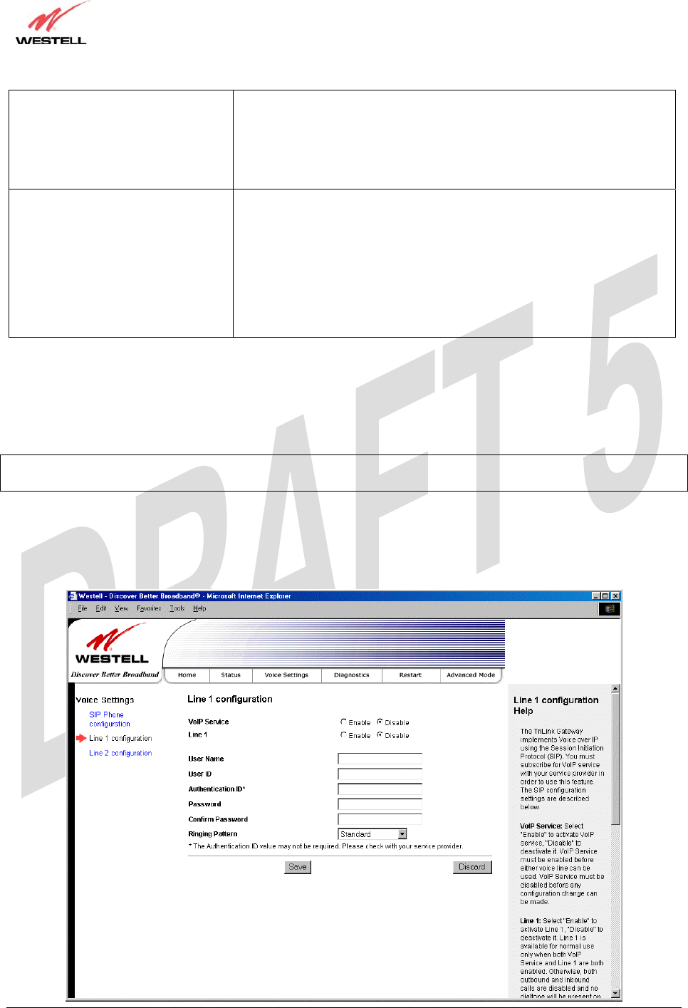
TriLink Gateway – Draft 5
030-300445 Rev. A
6/22/05
030-300445 Rev. A 52 June 2005
User Guide TriLink Gateway (Models 427V10, 427V11)
* – Represents the * character on you telephone keypad. In the example,
the digit map *XX. supports feature code dialing.
. – A period represents any arbitrary number of digits, including none.
[2-9] – Any single digit in the specified range.
[3,4,5] – Any single digit in the comma-separated list.
SIP Debug Level Factory Default = 0
Possible Response:
0 = Fatal
1 = Error
2 = Warn
3 = Notice
4 = Info
5 = Dbg
6 = Dbgv
13.2 Line 1 Configuration
The following screen will be displayed if you select Line 1 Configuration from the Voice Settings menu.
NOTE: By factory default, VoIP Service and Line 1 are disabled. Disabling VoIP Service will cancel any calls in
progress. VoIP service must be disabled in all screens before any configurations can be made to the screens.
When VoIP Service and Line 1 are disabled, you may enter the appropriate values in the fields provided. When you
are ready to enable VoIP Service, first click the Enable button for Line 1, and then click the Enable button for VoIP
Service (the fields in the screen will be dimmed and unavailable for further configuration). Next, click Save to save
your settings.

TriLink Gateway – Draft 5
030-300445 Rev. A
6/22/05
030-300445 Rev. A 53 June 2005
User Guide TriLink Gateway (Models 427V10, 427V11)
Line 1 Configuration
VoIP Service Factory Default = Disable
VoIP Service must be enabled before either voice line can be used. VoIP Service must be
disabled before any configuration changes can be made to the Line 1 Configuration
screen.
Possible Response:
Select Enable to activate your VoIP service.
Select Disable to deactivate your VoIP service.
Line 1 Factory Default = Disable
Line 1 is available for normal use only when both VoIP Service and Line 1 are enabled.
Otherwise, outbound and inbound calls are disabled and no dial tone will be present on
the line.
Possible Response:
Select Enable to activate Line 1.
Select Disable to deactivate Line 1.
User Name The subscriber’s name associated with Line 1.
User ID The user identifier associated with this line (provided by your service provider).
Authentication ID* The authentication ID associated with Line 1.
Password The user password associated with this line (provided by your service provider).
Confirm Password The confirm password value must be identical to your password.
Ringing Pattern Factory Default = Standard
The ringing pattern controls how the phone connected to Line 1 will ring when there is
an incoming call. The name in the drop down menu describes the ringing cadence.
Possible Response:
Standard
Long-Long
Short-Short-Long
Short-Long-Short
*Note: The Authentication ID value may not be required. Check with your service provider.
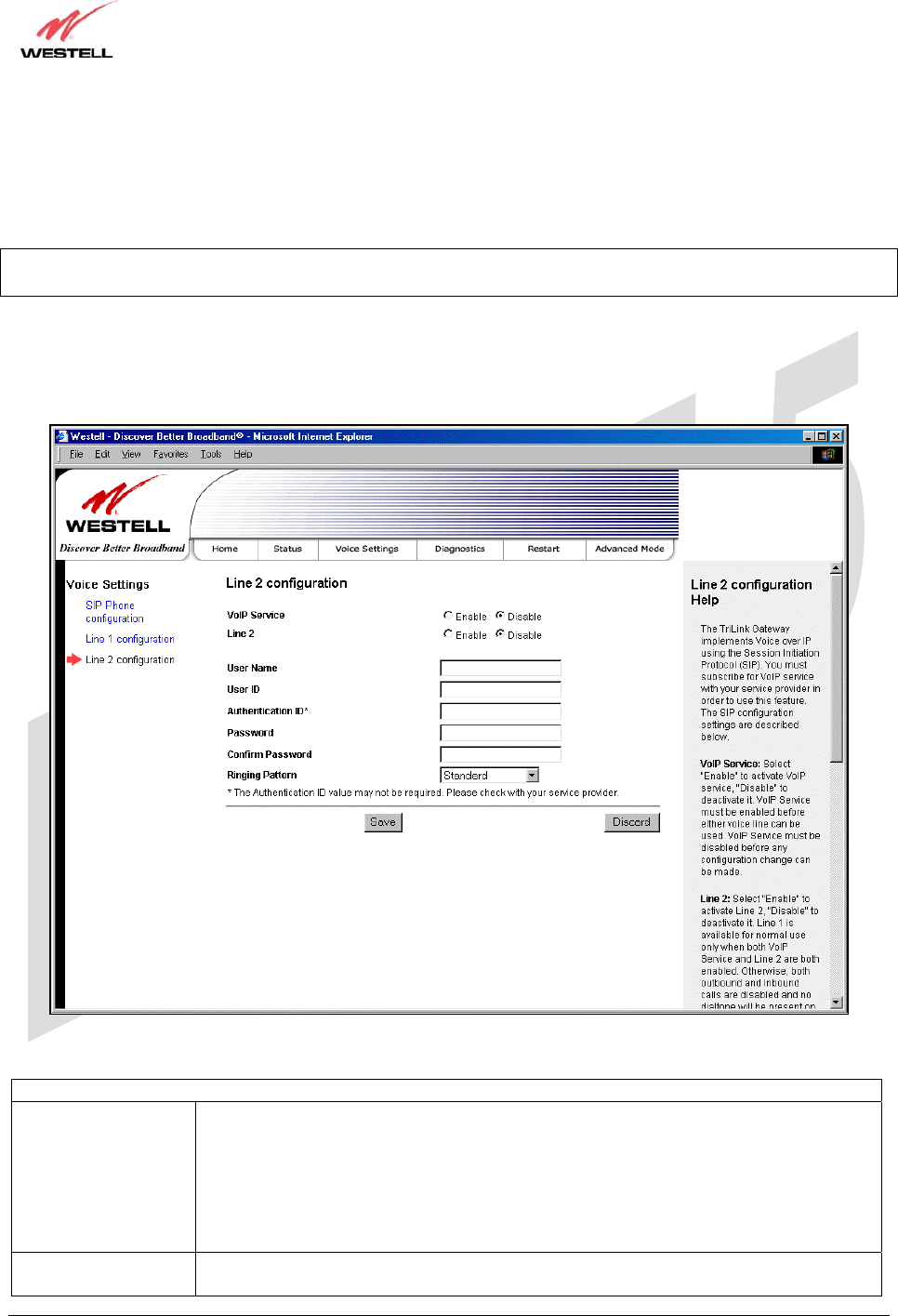
TriLink Gateway – Draft 5
030-300445 Rev. A
6/22/05
030-300445 Rev. A 54 June 2005
User Guide TriLink Gateway (Models 427V10, 427V11)
13.3 Line 2 Configuration
The following screen will be displayed if you select Line 2 Configuration from the Voice Settings menu.
NOTE: By factory default, VoIP Service and Line 2 are disabled. Disabling VoIP Service will cancel any calls in
progress. VoIP service must be disabled in all screens before any configurations can be made to the screens.
When VoIP Service and Line 2 are disabled, you may enter the appropriate values in the fields provided. When you
are ready to enable VoIP Service, first click the Enable button for Line 2, and then click the Enable button for VoIP
Service (the fields in the screen will be dimmed and unavailable for further configuration). Next, click Save to save
your settings.
Line 2 Configuration
VoIP Service Factory Default = Disble
VoIP Service must be enabled before either voice line can be used. VoIP Service must be
disabled before any configuration changes can be made to the Line 2 Configuration
screen.
Possible Response:
Select Enable to activate your VoIP service.
Select Disable to deactivate your VoIP service.
Line 2 Factory Default = Disble
Line 2 is available for normal use onl
y
when both VoIP Service and Line 2 are enabled.

TriLink Gateway – Draft 5
030-300445 Rev. A
6/22/05
030-300445 Rev. A 55 June 2005
User Guide TriLink Gateway (Models 427V10, 427V11)
Otherwise, outbound and inbound calls are disabled and no dial tone will be present on
the line.
Possible Response:
Select Enable to activate Line 2.
Select Disable to deactivate Line 2.
User Name The subscriber’s name associated with line.
User ID The user identifier associated with this line (provided by your service provider).
Authentication ID* The authentication ID associated with Line 2.
Password The user password associated with this line (provided by your service provider).
Confirm Password The confirm password value must be identical to your password.
Ringing Pattern Factory Default = Standard
Possible Response:
Standard
Long-Long
Short-Short-Long
Short-Long-Short
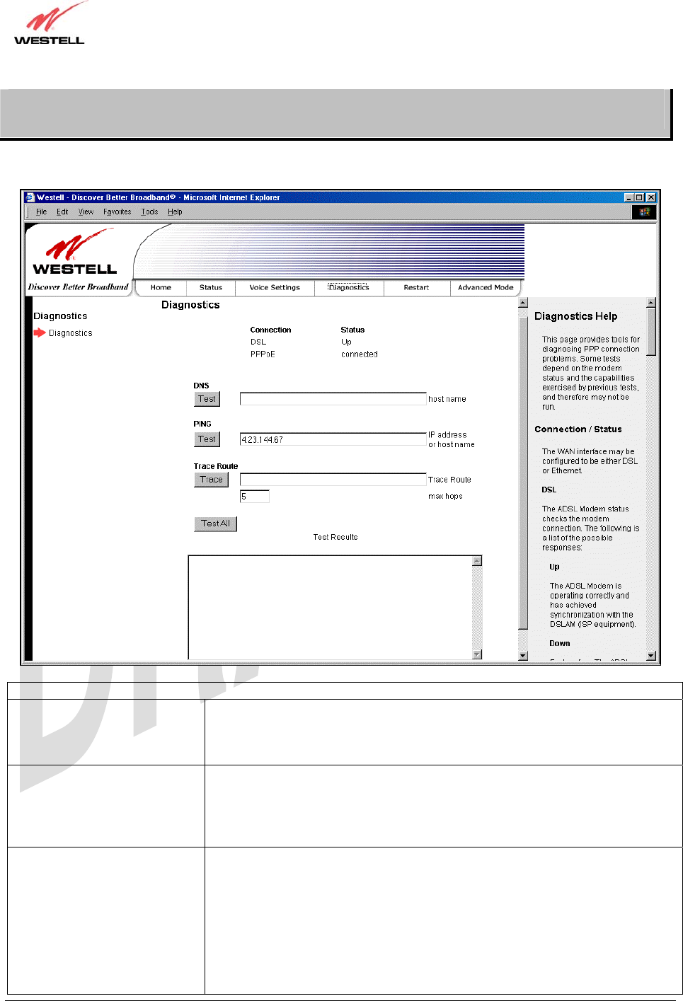
TriLink Gateway – Draft 5
030-300445 Rev. A
6/22/05
030-300445 Rev. A 56 June 2005
User Guide TriLink Gateway (Models 427V10, 427V11)
14. DIAGNOSTICS
The following screen will be displayed if you select Diagnostics from the Diagnostics main menu.
Connection/Status
DSL The Router checks the status of the DSL connection.
Possible responses are:
UP: The Router is operating correctly and has obtained DSL synchronization.
DOWN: The Router is operating correctly, but has not DSL synchronization.
PPPoE Indicates that a PPPoE session is or is not established.
Possible responses are:
Session Up: A valid PPPoE session has been detected.
No Session: Currently there is no active PPPoE session established.
Initiating Session: A PPP session must be connected from the homepage screen.
PPP Indicates that a PPPoE or session must already be established.
Possible responses are:
Connection UP: The Router has established a connection.
No Connection: There is no PPP connection.
Initiating Connection: The PPP connection process has been initiated.
Connection Halted: A successful PPP connection was halted.
Cannot Connect: A PPP connection could not be made because of a PPPoE
session failure.
Authorization Failure: The user name or password is incorrect.

TriLink Gateway – Draft 5
030-300445 Rev. A
6/22/05
030-300445 Rev. A 57 June 2005
User Guide TriLink Gateway (Models 427V10, 427V11)
Link Control Protocol Failed: The connection has been interrupted due to an LCP
error, and the Router is now trying to establish the session (from the home page).
Test Description / Test Results
Self Test Performs an integrity check of certain internal components of the Router.
PING ISP’s Router Performs an IP network check (i.e., an IP Ping) of the service provider’s Router.
This test verifies that the Router can exchange IP traffic with an entity on the
other side of the DSL line.
Possible responses are:
Success: The Router has detected an IP Remote Router connection.
No Response: The IP Remote Router does not answer the IP Ping.
Could not test: The test could not be executed due to the Router’s settings.
Check your DSL sync or your PPP session. You must have both a DSL sync
and a PPP connection established to execute a PING.
DNS Performs a test to try to resolve the name of a particular host. The host name is
entered in the input box.
Possible responses are:
Success: The Router has successfully obtained the resolved address. The IP
address is shown below the host name input box.
No Response: The Router has failed to obtain the resolved address.
Host not found: The DNS Server was unable to find an address for the given
host name.
No data, enter host name: No host name is specified.
Could not test: The test could not be executed due to the Router’s settings.
Check your DSL sync or your PPP session. You must have both a DSL sync
and a PPP connection established to execute a PING.
IP Address IP Address of the Host Name.
PING
(via IP Address or Host Name)
Performs an IP connectivity check to a remote computer either within or beyond
the Service Provider’s network. You can PING a remote computer via the IP
address or the DNS address. If your PING fails, try a different IP or DNS
address.
Possible responses are:
Success: The Remote Host computer was detected.
No Response: There was no response to the Ping from the remote computer.
No name or address to PING: No host name or IP address was specified.
Could not test: The test could not be executed due to the Router settings. Check
your DSL sync or your PPP session. You must have both a DSL sync and a PPP
connection established to execute a PING.
Trace Route
Determines the route taken to destination by sending Internet Control Message
Protocol (ICMP) echo packets with varying IP Time-To-Live (TTL) values to
the destination. Trace Route is used to determine where the packet is stopped on
the network.
Max hops The number of hops from the Router to the specified destination.
Test All Allows you to run a full diagnostic test.
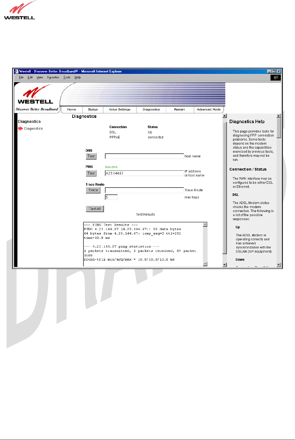
TriLink Gateway – Draft 5
030-300445 Rev. A
6/22/05
030-300445 Rev. A 58 June 2005
User Guide TriLink Gateway (Models 427V10, 427V11)
To perform a diagnostic test, type the appropriate value in any of the fields provided, and then click the Test button.
If you click Test All, the following screen will be displayed. The Test Results field will display information about
your modem’s diagnostic test.
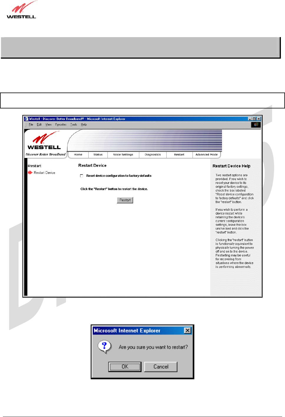
TriLink Gateway – Draft 5
030-300445 Rev. A
6/22/05
030-300445 Rev. A 59 June 2005
User Guide TriLink Gateway (Models 427V10, 427V11)
15. RESTART
The following screen will be displayed if you select Restart at the main menu. If you want to erase the stored
configuration, click on the check box labeled Restart device to configuration to factory defaults (a check mark
will appear in the box). Next, click the restart button to restart the Router.
Important: To reset the Router to factory default configuration, you must click the check box prior to clicking the
restart button. All custom configuration information will be erased.
After you click the restart button, the following pop-up screen will be displayed. Click OK to continue. Click cancel
if you do not want to restart the Router.
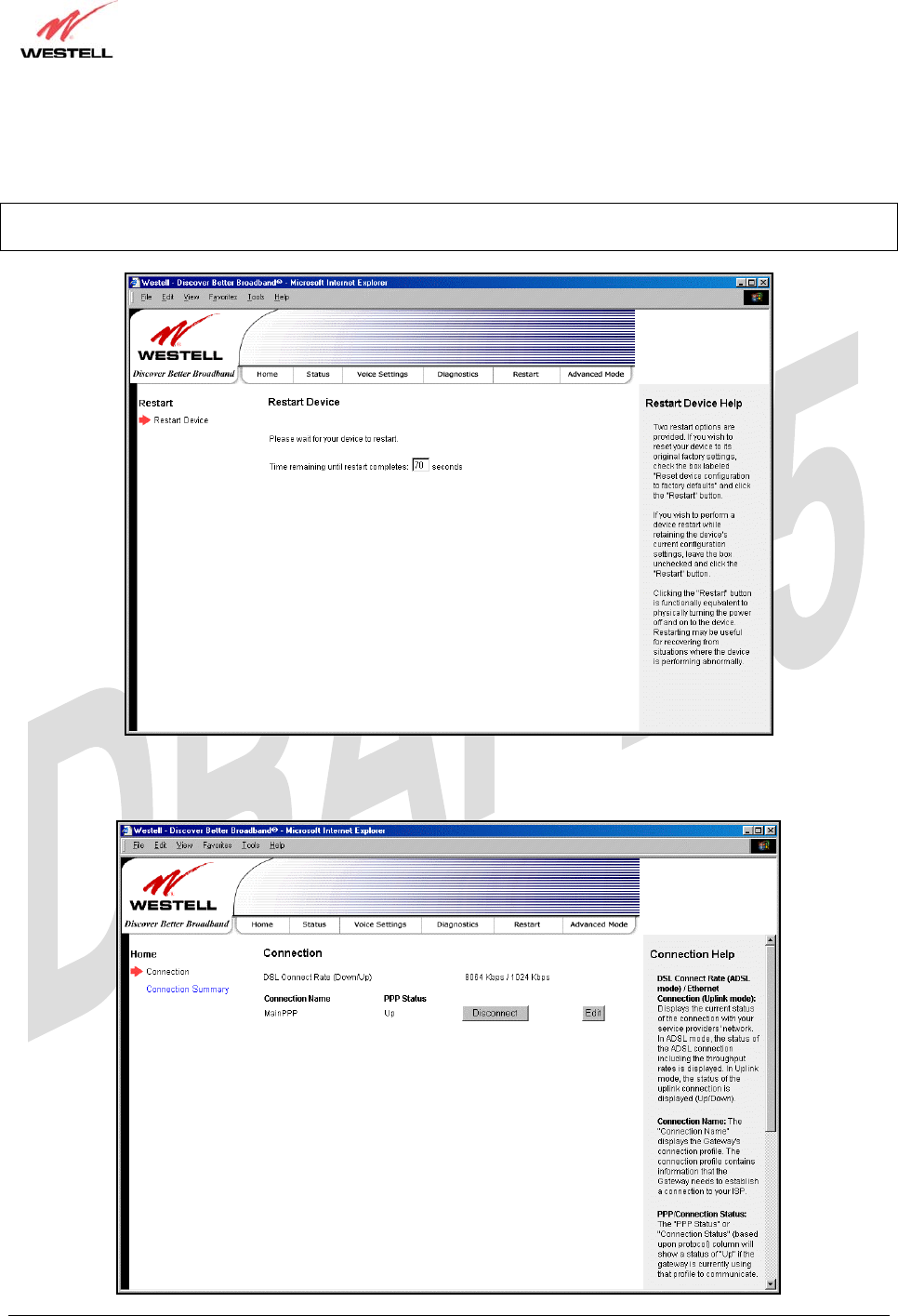
TriLink Gateway – Draft 5
030-300445 Rev. A
6/22/05
030-300445 Rev. A 60 June 2005
User Guide TriLink Gateway (Models 427V10, 427V11)
If you clicked OK in the preceding pop-up screen, the following screen will be displayed. Please wait for your
Router to restart. After your Router has restarted, the Edit Connection screen will be displayed.
Note: You may hear a click in the modem during restart. Please do not be alarmed as this will occur whenever the
modem restarts.
At the Edit Connection screen, confirm that the PPP Status field displays “Up” before you proceed with your
Router’s configuration.