Westell A90427XXX-07 Spread Spectrum Transmitter User Manual Part II
Westell Inc Spread Spectrum Transmitter Users Manual Part II
Westell >
Contents
- 1. Users Manual Part I
- 2. Users Manual Part II
Users Manual Part II
TriLink Gateway – Draft 5
030-300445 Rev. A
6/22/05
030-300445 Rev. A 61 June 2005
User Guide TriLink Gateway (Models 427V10, 427V11)
16. ADVANCED MODE
To set up the advanced configurations of your Router, select Advanced Mode (if you are in Basic Mode) from the
main menu. The following screen will be displayed.
NOTE: The basic operations of your Router were discussed earlier in this User Guide and provided details on the
Home, Status, Voice Settings, Diagnostics, and Restart features. For instructions on configuring any of these
features, refer to the Basic Mode sections (beginning with section 10) of this User Guide.
The advanced features of your Router will be discussed in sections 17, 18, and 19.
TriLink Gateway – Draft 5
030-300445 Rev. A
6/22/05
030-300445 Rev. A 62 June 2005
User Guide TriLink Gateway (Models 427V10, 427V11)
17. CONFIGURATION
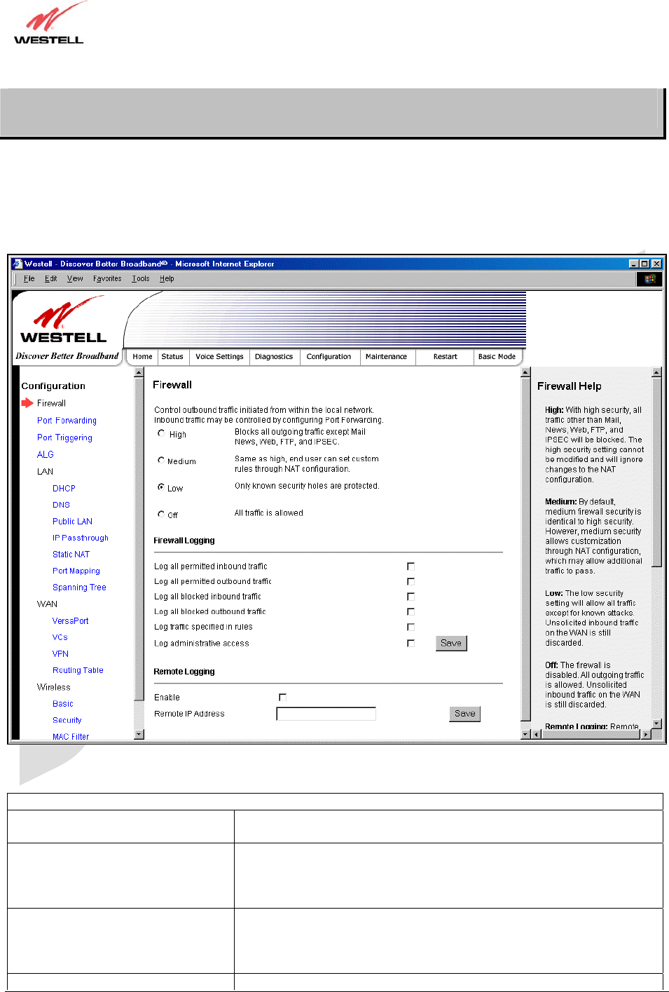
17.1 Firewall Configuration
The following screen will be displayed if you select Firewall from the Configuration menu. If you change any
settings in this screen, you must click save to save the settings.
Security Level
High High security level only allows basic Internet functionality. Only Mail,
News, Web, FTP, and IPSEC are allowed. All other traffic is prohibited.
Medium Like High security, Medium security only allows basic Internet
functionality by default. However, Medium security allows
customization through NAT configuration so that you can enable the
traffic that you want to pass.
Low Factory Default = Low
The Low security setting will allow all traffic except for known attacks.
If security is set to Low, the Router will be visible to other computers on
the Internet.
Off Firewall is disabled. (All traffic is passed)
TriLink Gateway – Draft 5
030-300445 Rev. A
6/22/05
030-300445 Rev. A 63 June 2005
User Guide TriLink Gateway (Models 427V10, 427V11)
Firewall Logging
Log all permitted inbound traffic Factory Default = Disabled
If Enabled (box is checked), this function will be activated.
Log all permitted outbound traffic Factory Default = Disabled
If Enabled (box is checked), this function will be activated.
Log all blocked inbound traffic Factory Default = Disabled
If Enabled (box is checked), this function will be activated.
Log all blocked outbound traffic Factory Default = Disabled
If Enabled (box is unchecked), this function will be activated.
Log traffic specified in rules Factory Default = Disabled
If Enabled (box is checked), this function will be activated.
Log administrative access Factory Default = Disabled
If Enabled (box is checked), this function will be activated.
Remote Logging
Enable Factory Default = Disable
If Enabled (box is checked), the Router will send firewall logs to a syslog
server.
Remote IP Address The IP address of the syslog server machine to which the diagnostics logs
to be sent.
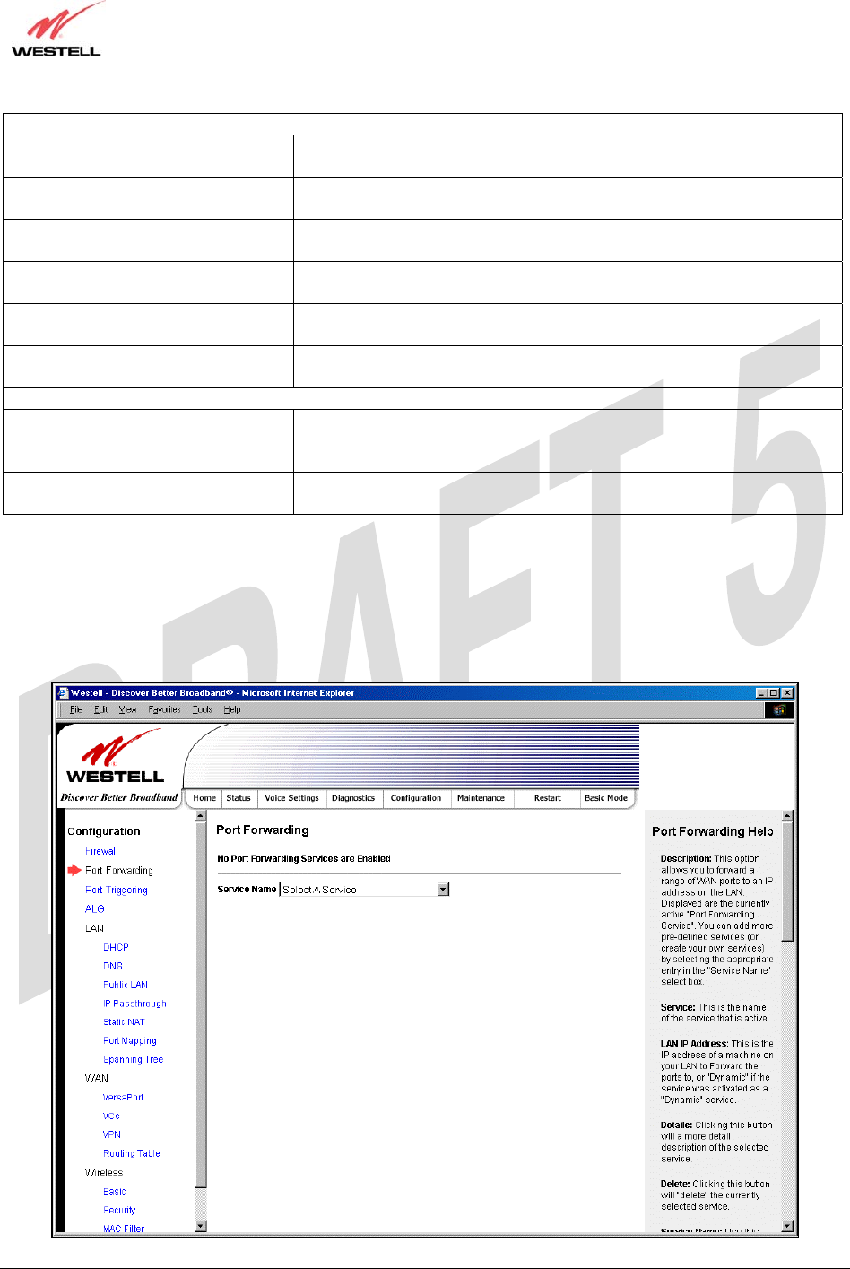
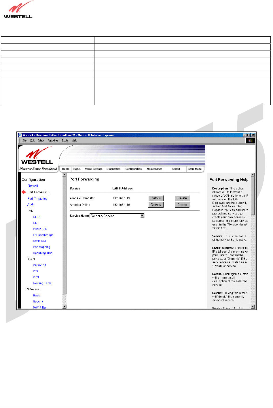
17.2 Port Forwarding Configuration
The following screen will be displayed if you select Port Forwarding from the Configuration menu. Port
Forwarding enables you to set up the Router’s port forwarding attributes for the services you add to your profile.
TriLink Gateway – Draft 5
030-300445 Rev. A
6/22/05
030-300445 Rev. A 64 June 2005
User Guide TriLink Gateway (Models 427V10, 427V11)
To set up port forwarding, select a service from the Service Name drop-down menu.
Note: You may add an unlimited numbers of services to your profile.
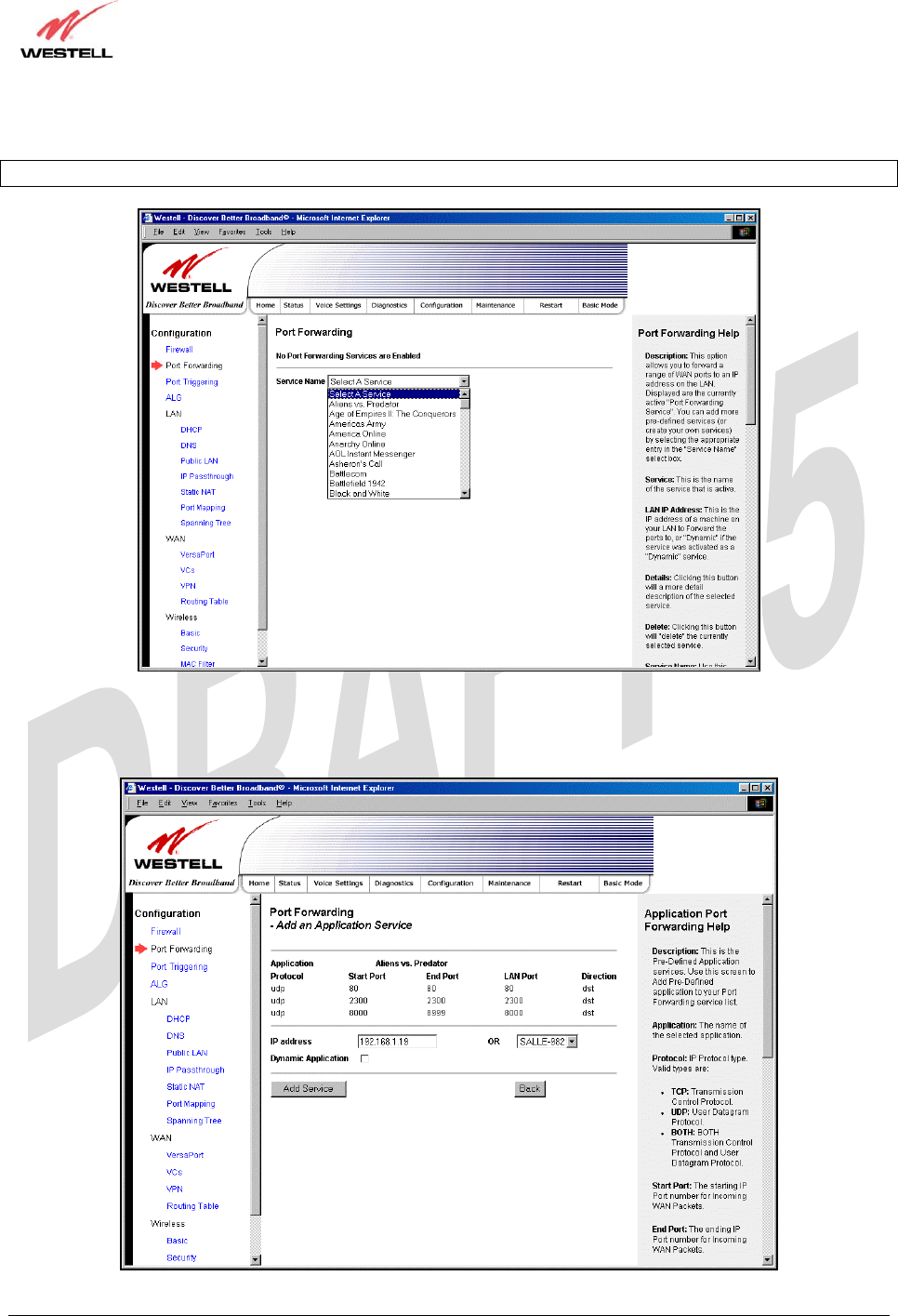
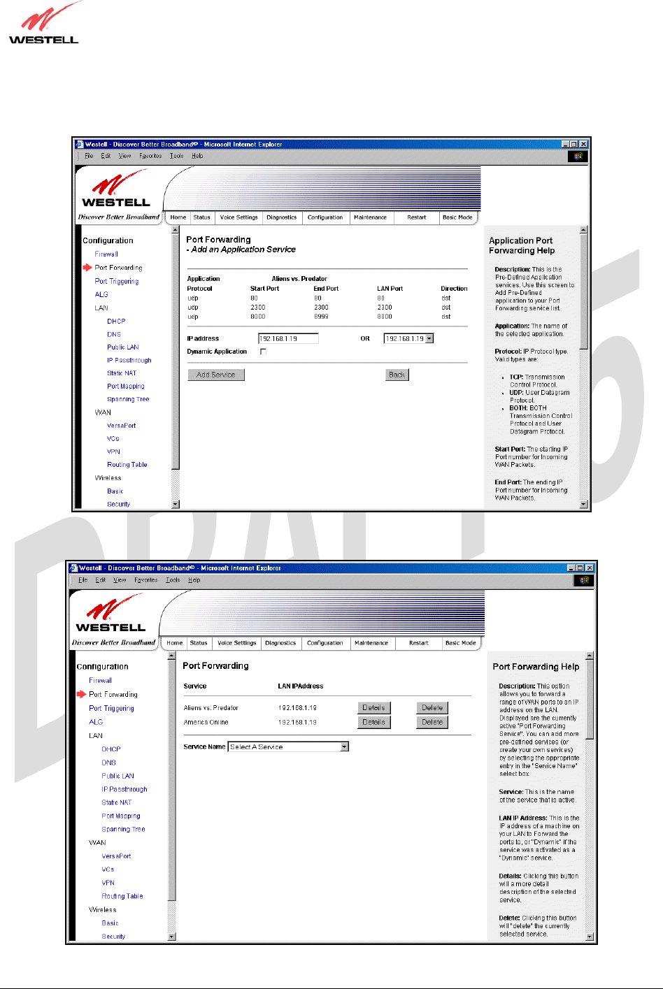
After you have selected a service name from the Service Name drop-down menu, the following Port Forwarding –
Add an Application Service screen will be displayed. Enter the appropriate IP address or machine name in the fields
provided and then click Add Service. Repeat these steps to add additional services to your profile.
TriLink Gateway – Draft 5
030-300445 Rev. A
6/22/05
030-300445 Rev. A 65 June 2005
User Guide TriLink Gateway (Models 427V10, 427V11)
Application Protocol The IP Protocol type that is assigned to this service.
Start Port The start port that is assigned to the service
End Port The end port that is assigned to the service
LAN Port The LAN port that is assigned to the service.
Direction The traffic direction assigned to the service.
IP Address The LAN IP address or the machine name assigned to your service
Dynamic Application Factory Default = Disabled
If Enabled (box is checked), this will only allow outgoing connections
from any local PC.
If Disabled, packets will be forwarded to the designated local PC.
If you clicked Add Service, the following screen will be displayed. To view the details of a service you have added,
click the Details button adjacent to the service you want to view.
TriLink Gateway – Draft 5
030-300445 Rev. A
6/22/05
030-300445 Rev. A 66 June 2005
User Guide TriLink Gateway (Models 427V10, 427V11)
If you clicked the Details button, the following screen will be displayed. After viewing the details of your service,
click Back to return to the preceding Port Forwarding screen.
To delete a service that you have added, click the Delete button adjacent to the service you want to remove.
TriLink Gateway – Draft 5
030-300445 Rev. A
6/22/05
030-300445 Rev. A 67 June 2005
User Guide TriLink Gateway (Models 427V10, 427V11)
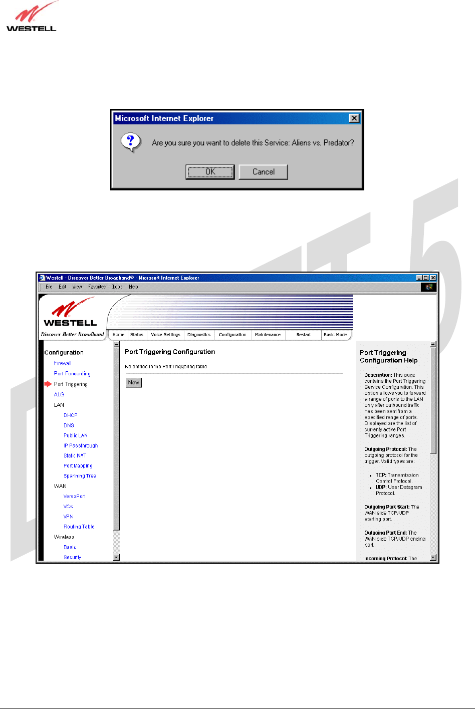
If you clicked Delete in the preceding screen, the following pop-up screen will be displayed. Click OK in the pop-
up screen; the service will then be removed from the list of selected services. Click Cancel if you do not want to
delete the selected service.
17.3 Port Triggering
The following screen will be displayed if you select Port Triggering from the Configuration menu. To create a trigger
port, click New.
TriLink Gateway – Draft 5
030-300445 Rev. A
6/22/05
030-300445 Rev. A 68 June 2005
User Guide TriLink Gateway (Models 427V10, 427V11)
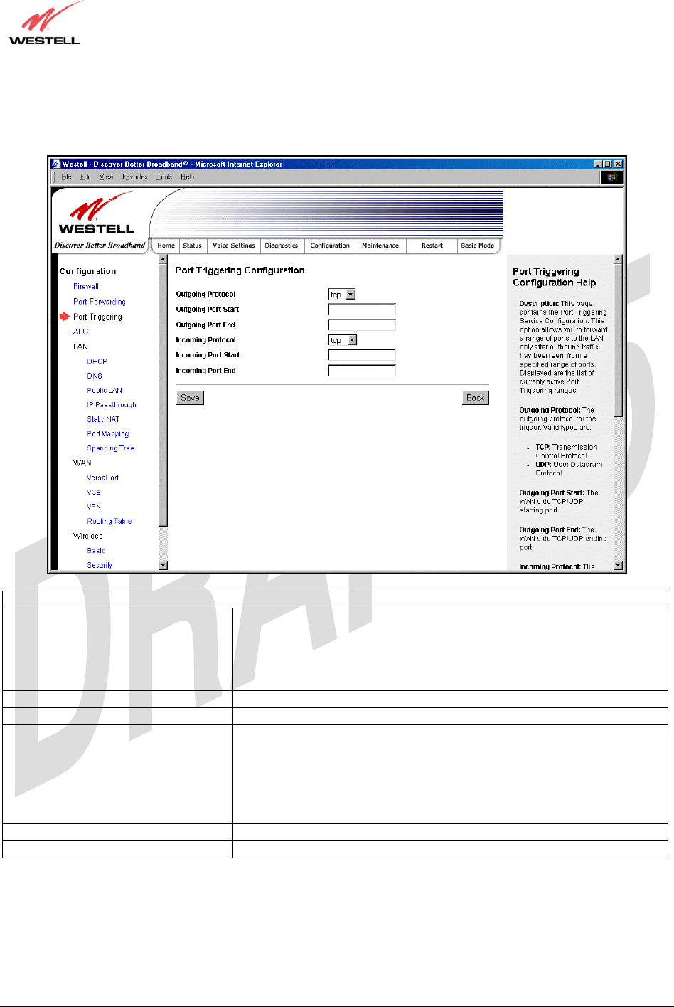
If you clicked New, the following screen will be displayed. Enter the appropriate values and click Save to save your
settings.
Port Triggering Configuration
Outgoing Protocol Factory Default = TCP
The outgoing protocol for the triggered ports.
Possible Response:
TCP – Transmission Control Protocol
UDP – User Datagram Protocol
Outgoing Port Start The WAN-side TCP/UDP starting port
Outgoing Port End The WAN-side TCP/UDP ending port
Incoming Protocol Factory Default = TCP
The incoming protocol for the triggered ports.
Possible Response:
TCP- Transmission Control Protocol
UDP- User Datagram Protocol
Both – TCP and UDP
Incoming Port Start The local LAN-side starting port.
Incoming Port End The local LAN-side ending port.
TriLink Gateway – Draft 5
030-300445 Rev. A
6/22/05
030-300445 Rev. A 69 June 2005
User Guide TriLink Gateway (Models 427V10, 427V11)
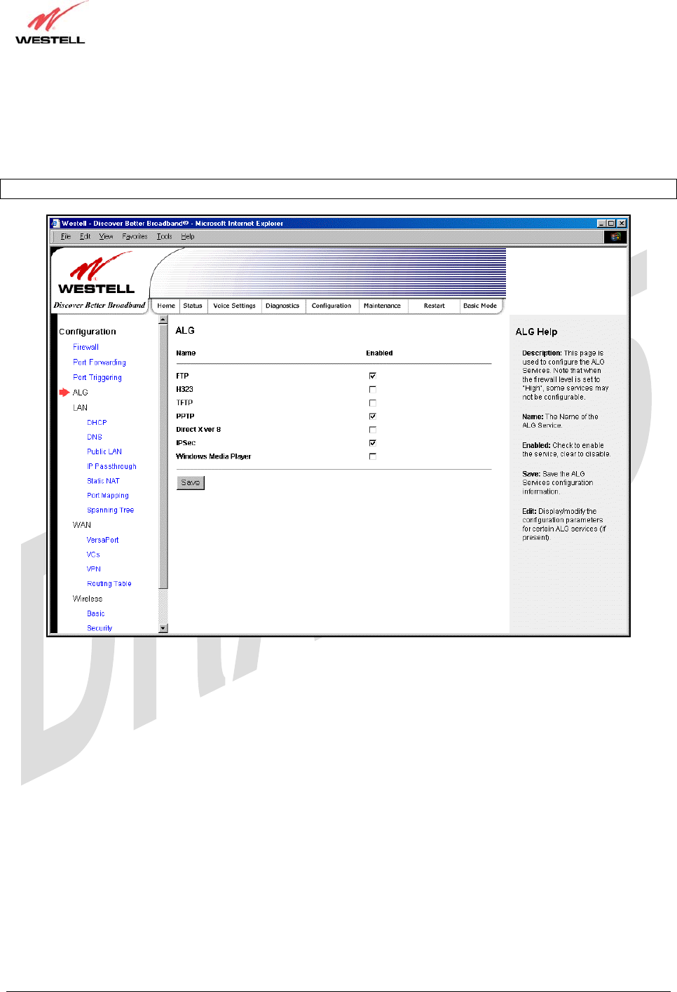
17.4 ALG Configuration
The following screen will be displayed if you select ALG from the Configuration menu. This page enables you to
configure ALG services for your Router. Enter the appropriate settings and then click Save to save the settings.
Note: When the firewall level is set to “High,” some services may not be configurable.
TriLink Gateway – Draft 5
030-300445 Rev. A
6/22/05
030-300445 Rev. A 70 June 2005
User Guide TriLink Gateway (Models 427V10, 427V11)
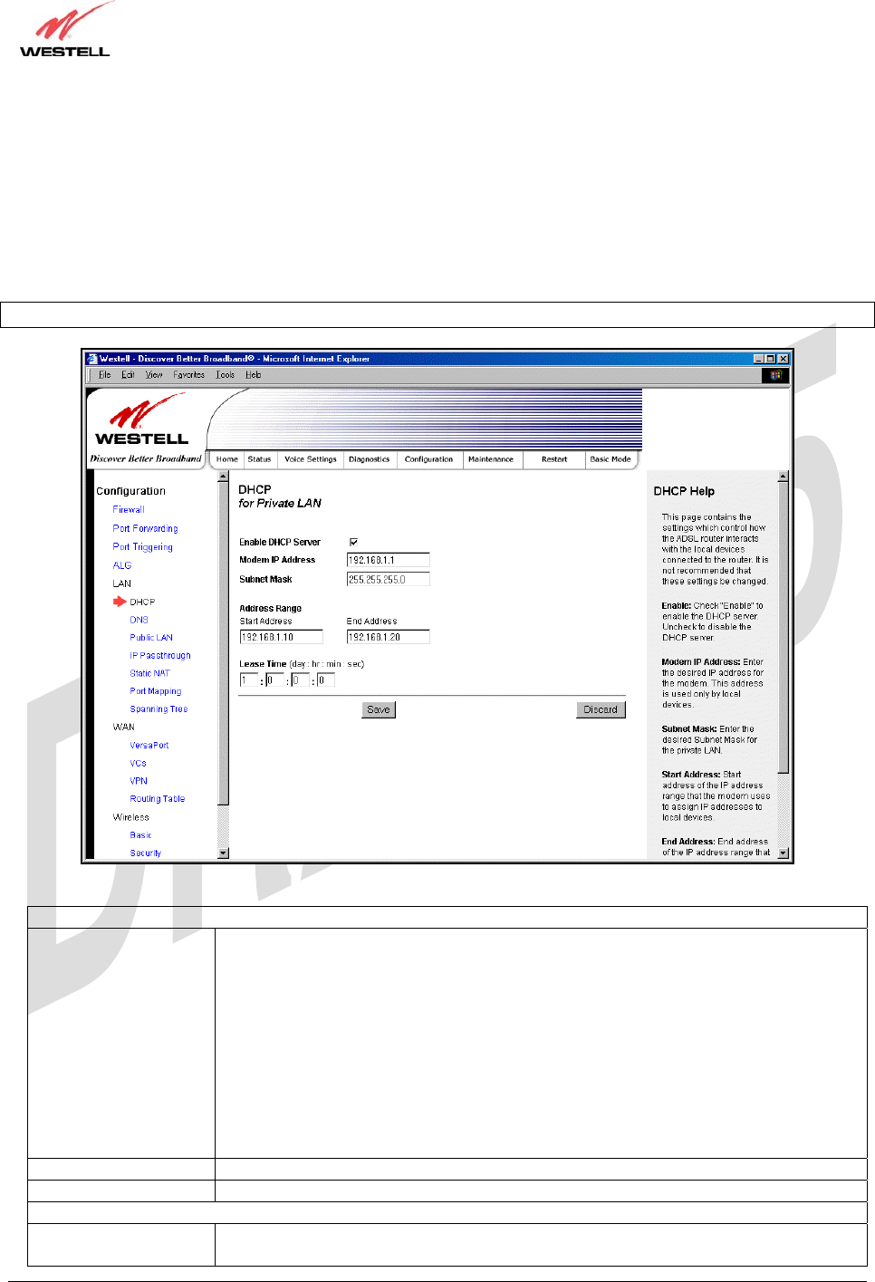
17.5 LAN Configuration
17.5.1 DHCP
The following screen will be displayed if you select LAN > DHCP from the Configuration menu. This page enables
you to control how the Router interacts with local devices to which it is connected. Enter the appropriate values, and
then click Save to save your settings.
Note: Westell recommends that you do not change these settings unless instructed by your Internet service provider.
DHCP Configuration for Private LAN
Enable DHCP Server Factory Default = Enable
This setting allows the Router to automatically assign IP addresses to local devices
connected on the LAN. Westell advises setting this to enabled for the private LAN.
Private LAN = DHCP addresses will be saved into the Private LAN configuration.
Public LAN = DHCP addresses will be saved into the Public LAN configuration. (This
option is only available if the Public LAN DHCP server is enabled.)
Possible Response:
If this box is checked, the DHCP server will be turned On.
If this box is unchecked, the DHCP server will be turned Off.
NOTE: These addresses will be overwritten if the Internet Service Provider supports
dynamic setting of these values.
Modem IP Address The IP Address of the Router
Subnet Mask The Subnet Mask of the Router
Address Range
DHCP Start Address Factory Default = 192.168.1.10
This field dis
p
la
y
s the first IP address that the DHCP server will
p
rovide. The DHCP
TriLink Gateway – Draft 5
030-300445 Rev. A
6/22/05
030-300445 Rev. A 71 June 2005
User Guide TriLink Gateway (Models 427V10, 427V11)
Start Address must be within the IP address and lower than the DHCP End Address.
You may use any number from 0 to 254 in this address.
DHCP End Address Factory Default = 192.168.1.20
This field displays the last IP address that the DHCP server will provide. The DHCP
End Address must be within the IP address and higher than the DHCP Start Address.
You may use any number from 0 to 254 in this address.
DHCP Lease Time Factory Default = 01:00:00:00
Displays the amount of time the provided addresses will be valid, after which the
DHCP client will usually re-submit a request.
NOTE: DHCP Lease Time is displayed in the format (day:hour:min:sec)*. This value
must be greater than 10 seconds. Seconds must be between 0 and 59, minutes must be
between 0 and 59, and hours must be between 0 and 23.
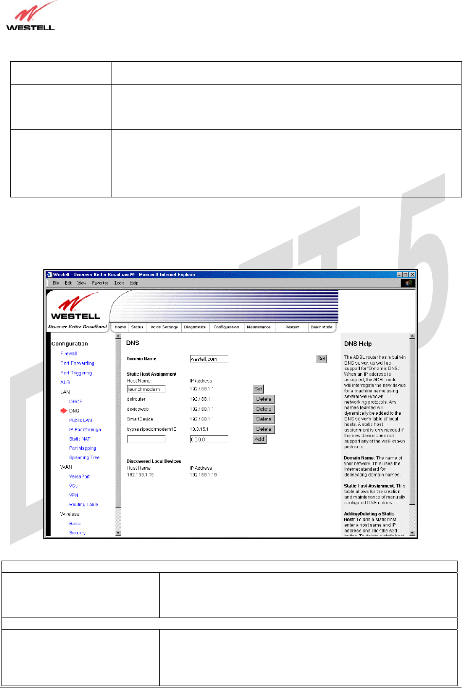
17.5.2 DNS
The following screen will be displayed if you select LAN > DNS from the Configuration menu.
DNS
Domain Name
NOTE: Some ISP’s may require the
name for identification purposes.
This field allows you to enter a Domain Name for the Router.
To add a Domain Name, in the field under User Assigned DNS, type in
your new domain name and click Set.
Static Host Assignment
Host Name This field allows you to enter a HOST name for the Router.
To add a new Host name, in the field under Static Host Assignment, type
in the Host Name and the associated IP address and then click Add.
To delete a Host name, click the Delete button adjacent to the Host Name
and IP Address you want to delete.
TriLink Gateway – Draft 5
030-300445 Rev. A
6/22/05
030-300445 Rev. A 72 June 2005
User Guide TriLink Gateway (Models 427V10, 427V11)
IP Address Displays the IP address that is assigned to the Host Name.
Discovered Local Devices
This field displays a list of the computers on the LAN that have been assigned a DHCP Address. The DNS name
and IP address entry of each discovered device is displayed. (NOTE: The values in this field will be displayed
barring any propagation delays. If ‘No Discovered Devices’ is displayed, manually refresh the screen.)
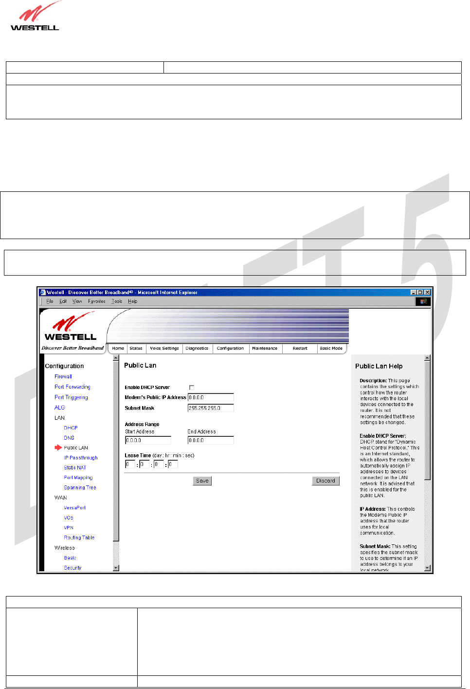
17.5.3 Public LAN – Multiple IP Address Passthrough
The following screen will be displayed if you select LAN > Public LAN from the Configuration menu.
NOTE: Selecting Public LAN will enable the VersaPort™2 port to function as an Ethernet LAN port allowing your
Router to use LAN IP addresses that accessible from the WAN. This allows your computer to have global address
ability. To use the Public LAN feature on the Router, your ISP must support Public LAN and Static IP. Contact your
ISP for details. When VersaPort™2 is configured for Public LAN, the Router’s DSL transceiver will be enabled.
Important: By enabling the Public LAN DHCP Server, you automatically disable the Private LAN DHCP Server on
your Router.
Public LAN Settings
Enable DHCP Server Factory Default = Disable
Possible Response:
If Enabled (box is checked), this will enable the Public LAN DHCP server and
allow IP address to be server from the DHCP Public LAN pool.
If Disabled (the box is unchecked), this will disable the Public LAN DHCP
server.
Modem’s Public IP Address The Router’s public IP address

TriLink Gateway – Draft 5
030-300445 Rev. A
6/22/05
030-300445 Rev. A 73 June 2005
User Guide TriLink Gateway (Models 427V10, 427V11)
Subnet Mask The Subnet Mask, which determines what portion of an IP address is controlled
by the network and which portion is controlled by the host.
Address Range
DHCP Start Address Displays the first IP address that the Public LAN DHCP Server will provide.
The DHCP Start Address must be within the IP address and lower than the
DHCP End Address.
DHCP End Address Displays the last IP address that the Public LAN DHCP Server will provide.
The DHCP End Address must be within the IP address and higher than the
DHCP Start Address.
DHCP Lease Time Factory Default = 01:00:00:00
Displays the amount of time the provided addresses will be valid, after which
time the Public LAN DHCP client will usually re-submit a request.
NOTE: DHCP Lease Time is displayed in the format (day:hour:min:sec)*. This
value must be greater than 10 seconds. Seconds must be between 0 and 59,
minutes must be between 0 and 59, and hours must be between 0 and 23.
If the settings you have entered in the Public LAN Settings fields are incorrect, the following warnings messages
may be displayed via pop-up screens. If this occurs, check the Public LAN settings.
Warning Message Check Public LAN DHCP Settings
Start Address is not part of the Subnet Check the value in the DHCP Start Address field
End Address is not part of the Subnet Check the value in the DHCP End Address field
End Address is below the Start Address Check the value in the DHCP End Address field
Lease time must be greater than 10 seconds Check the values in the DHCP Lease Time fields
Seconds must be between 0 and 59 Check the Seconds field at DHCP Lease Time
Minutes must be between 0 and 59 Check the Minutes field at DHCP Lease Time
Hours must be between 0 and 23 Check the Hours field at DHCP Lease Time
17.5.4 IP Passthrough – Single IP Address Passthrough
IP Passthrough enables you to select the device on your LAN that will share your Single Static IP address. Before
you begin this section, configure your PC settings to obtain an IP address from your Router automatically. (Refer to
your computer’s Windows® Help screen for instructions.)
NOTE: IP Passthrough enables the user to share the WAN assigned IP address with one device on the LAN. By
doing this, the device with the single static IP address becomes visible on the Internet. Network Address Translation
(NAT) and Firewall rules do not apply to the device configured for IP Passthrough. If you are using Routed IP
protocol, IP Passthrough configuration will not be available.
TriLink Gateway – Draft 5
030-300445 Rev. A
6/22/05
030-300445 Rev. A 74 June 2005
User Guide TriLink Gateway (Models 427V10, 427V11)
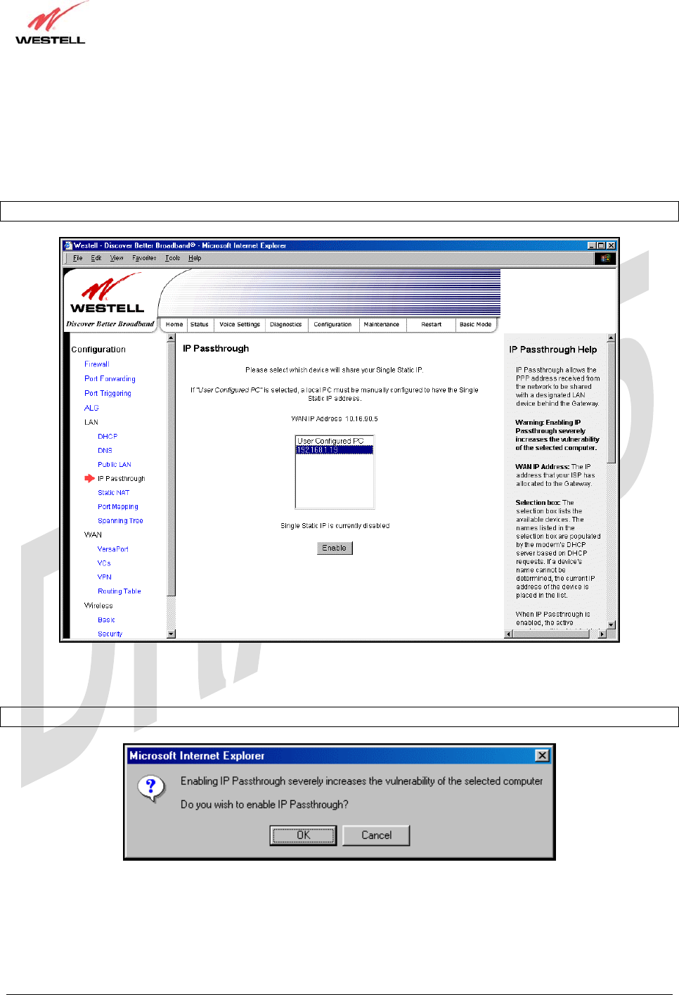
17.5.4.1 Enabling IP Passthrough – Single IP Address PassThrough
(Applicable for PPPoE or PPPoA Connections Only)
To enable IP Passthrough, select a device that will share your Single Static IP from the options listed in the window.
This screen enables you to select the device on your LAN that will share your Single Static IP. Click on enable.
NOTE: The actual device name may differ from the name displayed in this screen.
If you clicked Enable, the following pop-up screen will be displayed. Click OK to continue.
Warning: Enabling IP Passthrough severly increases the vulnerability of the selected computer.
TriLink Gateway – Draft 5
030-300445 Rev. A
6/22/05
030-300445 Rev. A 75 June 2005
User Guide TriLink Gateway (Models 427V10, 427V11)
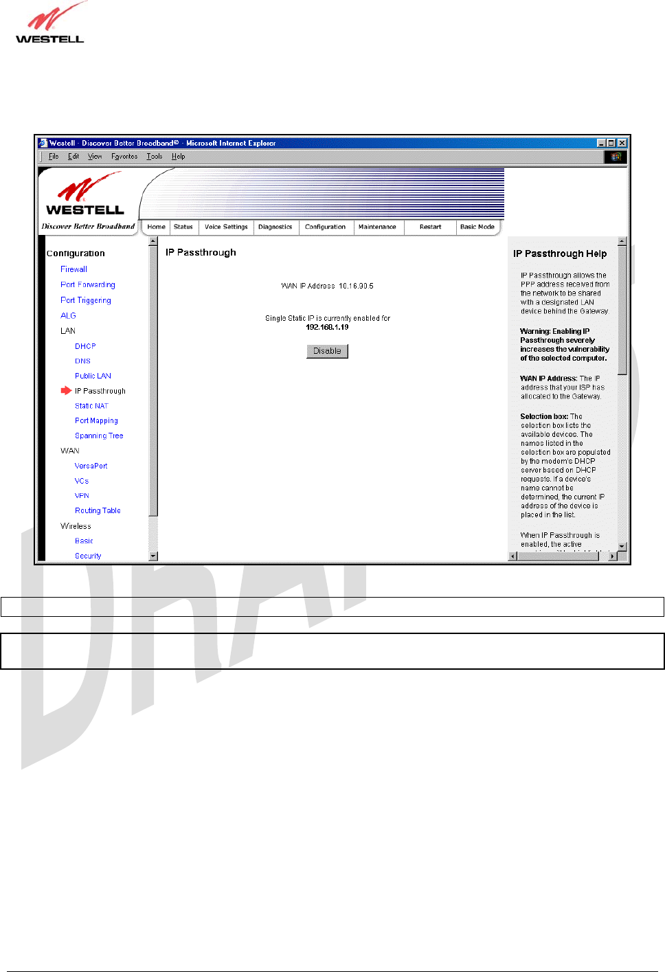
If you clicked OK in the preceding pop-up screen, the Router will be reset and the new configuration will take effect,
as shown in the following screen.
STOP! After you enable IP Passthrough, you must reboot your computer.
NOTE: If you chose to enable User Configured PC, wait for the Router to reset and then manually enter the WAN
IP, Gateway, and Subnet mask addresses you obtained from your Internet service provider into a PC.
TriLink Gateway – Draft 5
030-300445 Rev. A
6/22/05
030-300445 Rev. A 76 June 2005
User Guide TriLink Gateway (Models 427V10, 427V11)
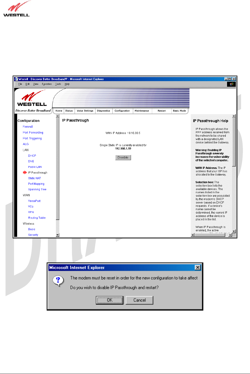
17.5.4.2 Disabling IP Passthrough – Single IP Address PassThrough
To disable IP Passthrough (if it has been previously enabled), select IP Passthrough from the Configuration>LAN
menu. Click on Disable.
If you clicked Disable following pop-up screen will be displayed. Click OK to continue.
TriLink Gateway – Draft 5
030-300445 Rev. A
6/22/05
030-300445 Rev. A 77 June 2005
User Guide TriLink Gateway (Models 427V10, 427V11)
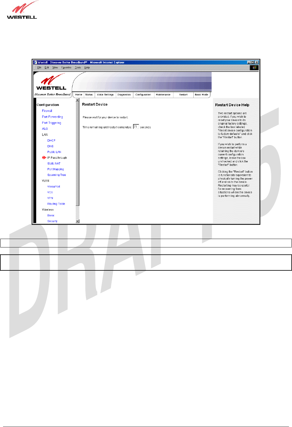
If you clicked OK in the preceding pop-up screen, the following screen will be displayed. The Router will be reset
and the new configuration will take effect.
STOP! After you disable IP Passthrough, you must reboot your computer.
NOTE: If you chose to enable User Configured PC, wait for the Router to reset and then manually enter the WAN
IP, Gateway, and Subnet mask addresses you obtained from your Internet service provider into a PC.
TriLink Gateway – Draft 5
030-300445 Rev. A
6/22/05
030-300445 Rev. A 78 June 2005
User Guide TriLink Gateway (Models 427V10, 427V11)
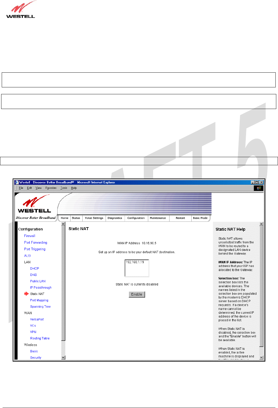
17.5.5 Static NAT
The following screen will be displayed if you select LAN > Static NAT from the Configuration menu. This screen
enables you to configure your Router to work with the special NAT services.
NOTE: When the Router is configured for Static NAT, any unsolicited packets arriving at the WAN would be
forwarded to this device. This feature is used in cases where the user wants to host a server for a specific application.
STOP: IP Passthough must be disabled (if it has been previously enabled) before you enable static NAT. Refer to
section 17.5.4.2 for instructions on disabling IP Passthrough.
17.5.5.1 Enabling Static NAT
To enable Static NAT, select an IP address or device name from the options listed in the Static NAT screen and then
click Enable.
NOTE: The actual IP addresses or device names may differ from the those displayed in the following screen.
TriLink Gateway – Draft 5
030-300445 Rev. A
6/22/05
030-300445 Rev. A 79 June 2005
User Guide TriLink Gateway (Models 427V10, 427V11)
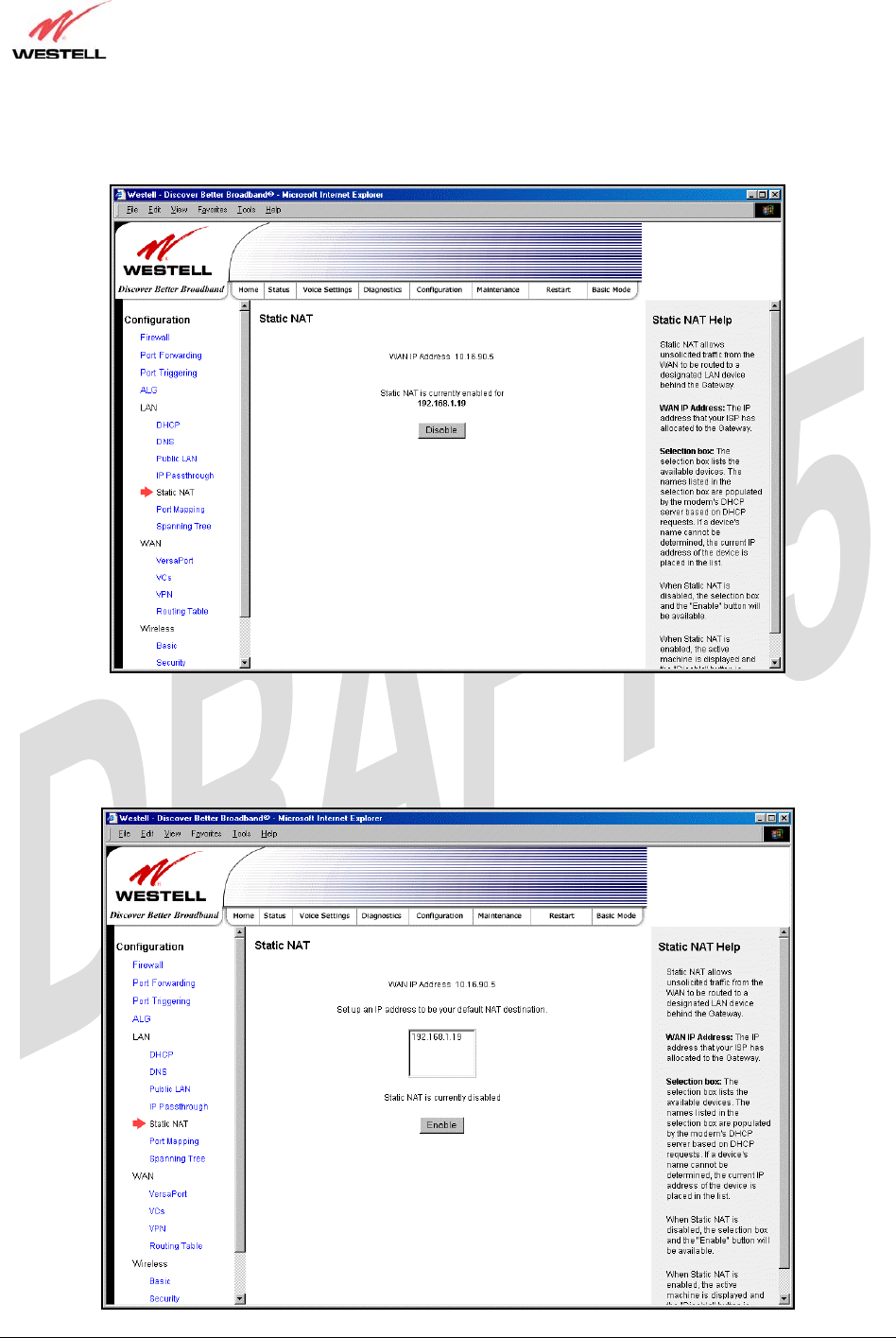
If you clicked Enable, the following screen will be displayed, with Static NAT enabled for the IP address or device
name you selected.
17.5.5.2 Disabling Static NAT
To disable Static NAT, click Disable in the Static NAT screen. The following screen will be displayed.
TriLink Gateway – Draft 5
030-300445 Rev. A
6/22/05
030-300445 Rev. A 80 June 2005
User Guide TriLink Gateway (Models 427V10, 427V11)
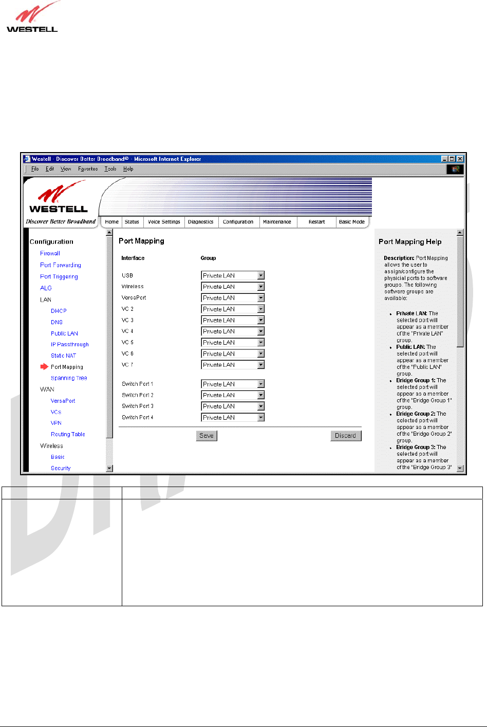
17.5.6 Port Mapping
The following screen will be displayed if you select LAN > Port Mapping from the Configuration menu. This
screen enables you to assign the physical ports to software groups. Enter the appropriate values, and then click save
to save your settings.
Interface The physical ports available for mapping
Group Factory Default: Private LAN
The software defined virtual LAN group to which the port should be assigned:
Possible Responses:
Private LAN
Public LAN
Bridge Group One
Bridge Group Two
Bridge Group Three
Bridge Group Four
TriLink Gateway – Draft 5
030-300445 Rev. A
6/22/05
030-300445 Rev. A 81 June 2005
User Guide TriLink Gateway (Models 427V10, 427V11)
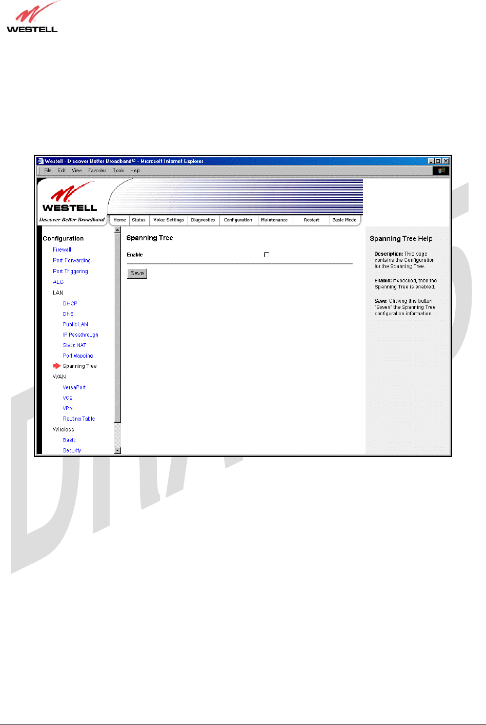
17.6 Spanning Tree
The following screen will be displayed if you select LAN > Port Mapping from the Configuration menu. This
screen enables you to assign the Router’s physical ports to software groups. To enable Spanning Tree functionality
for your Router, click the box adjacent to Enable (a check mark will appear in the box). Next, click Save to save
your settings.
TriLink Gateway – Draft 5
030-300445 Rev. A
6/22/05
030-300445 Rev. A 82 June 2005
User Guide TriLink Gateway (Models 427V10, 427V11)
17.7 WAN Configuration
17.7.1 VersaPort
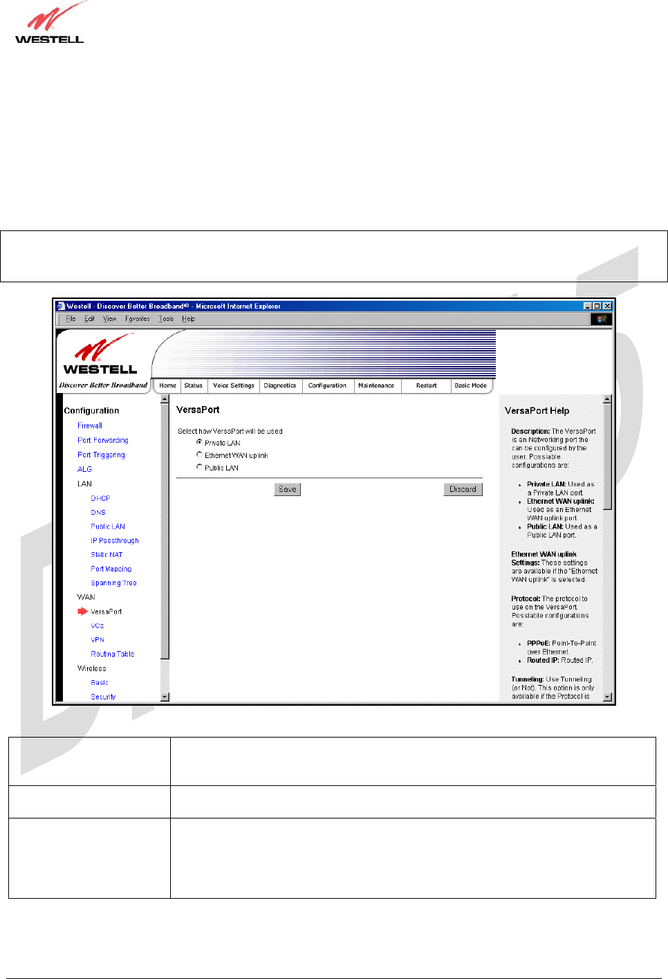
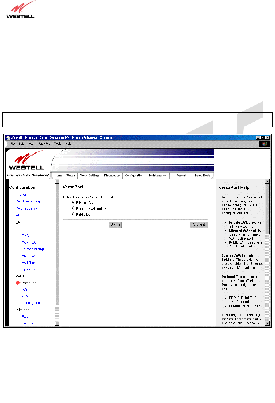
The following screen will be displayed if you select VersaPort from the Configuration menu. This function will
enable you to configure the VersaPort settings for your Router. From the options provided, select how VersaPort will
be used (Private LAN, Ethernet WAN Uplink, or Public LAN). Next, click Save to save your settings.
Important: Prior to configuring your Router’s VersaPort settings, please confirm that you are connected to the
VersaPort on your Router. Refer to section 6.4.2 (Installation via VersaPort) for details on your Router’s hardware
installation procedures.
Private LAN If selected, the VersaPort will function as a fifth Ethernet LAN port. Private LAN
allows you to set up a network behind the Router. When using Private LAN, the
Router’s DSL transceiver will be Enabled.
Ethernet WAN Uplink If selected, the VersaPort will function as an Ethernet WAN Uplink port, and the
Router’s DSL transceiver will be Disabled.
Public LAN If selected, the VersaPort will function as an Ethernet LAN port allowing your
Router to use LAN IP addresses that accessible from the WAN. This allows your
computer to have global address ability. To use the Public LAN feature on the
Router, your ISP must support Public LAN and Static IP. Contact your ISP for
details. When using Public LAN, the Router’s DSL transceiver will be Enabled.
TriLink Gateway – Draft 5
030-300445 Rev. A
6/22/05
030-300445 Rev. A 83 June 2005
User Guide TriLink Gateway (Models 427V10, 427V11)
17.7.2 Private LAN – Configuring NAT
If you select Private LAN in the VersaPort screen, the following screen will be displayed. Private LAN enables you
to set up a network behind the Router. After you have entered the appropriate values, click Save to save your
settings.
NOTE: Selecting Private LAN will enable you to set up a network behind your Router. When your Router is
configured for Private LAN, the VersaPort port functions as fifth Ethernet LAN port. To connection additional PCs
to your Router, use the four black Ethernet ports on the rear of the Router as they function as an Ethernet switch.
(Private LAN is the default VersaPort Configuration for your Router.)
Important: By enabling the Private LAN DHCP Server, you automatically disable the Public LAN DHCP Server on
your Router.

TriLink Gateway – Draft 5
030-300445 Rev. A
6/22/05
030-300445 Rev. A 84 June 2005
User Guide TriLink Gateway (Models 427V10, 427V11)
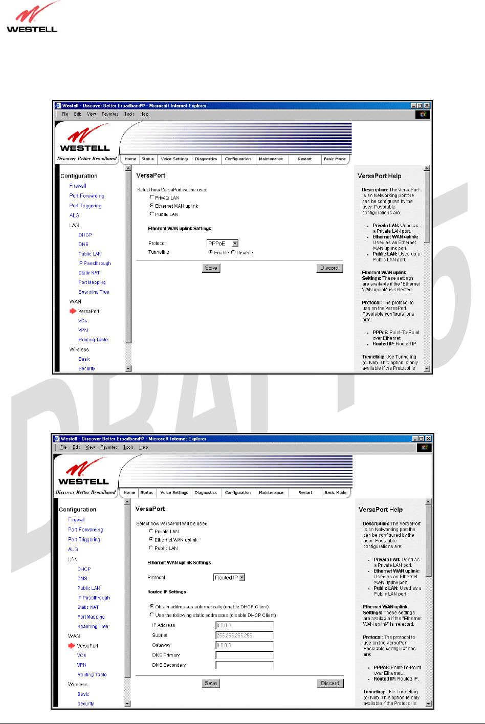
17.7.3 Ethernet WAN Uplink
If you select Ethernet WAN Uplink in the VersaPort Configuration screen, the following screen will be
displayed.
NOTE: Selecting Ethernet WAN Uplink will allow the Router’s WAN interface to use the VersaPort. This will
disable the Router’s DSL transceiver.
TriLink Gateway – Draft 5
030-300445 Rev. A
6/22/05
030-300445 Rev. A 85 June 2005
User Guide TriLink Gateway (Models 427V10, 427V11)
If you select PPPoE as the protocol for your Ethernet WAN Uplink setting, the following screen will be displayed.
Click Save to save your settings.
If you select Routed IP as the protocol for your Ethernet WAN Uplink setting, the following screen will be
displayed. Enter the appropriate values in the fields provided, and then click Save to save your settings.
TriLink Gateway – Draft 5
030-300445 Rev. A
6/22/05
030-300445 Rev. A 86 June 2005
User Guide TriLink Gateway (Models 427V10, 427V11)
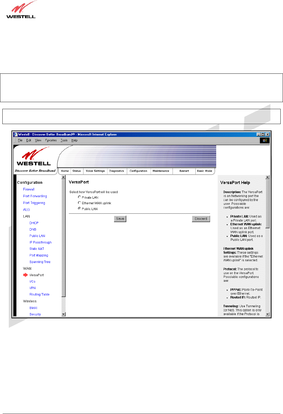
17.7.4 Public LAN – Multiple IP Address Passthrough
If you select Public LAN in the VersaPort Configuration screen, the following screen will be displayed.
NOTE: Selecting Public LAN will enable the VersaPort will function as an Ethernet LAN port allowing your Router
to use LAN IP addresses that accessible from the WAN. This allows your computer to have global address ability. To
use the Public LAN feature on the Router, your ISP must support Public LAN and Static IP. Contact your ISP for
details. When VersaPort is configured for Public LAN, the Router’s DSL transceiver will be enabled.
Important: By enabling the Public LAN DHCP Server, you automatically disable the Private LAN DHCP Server on
your Router.
TriLink Gateway – Draft 5
030-300445 Rev. A
6/22/05
030-300445 Rev. A 87 June 2005
User Guide TriLink Gateway (Models 427V10, 427V11)
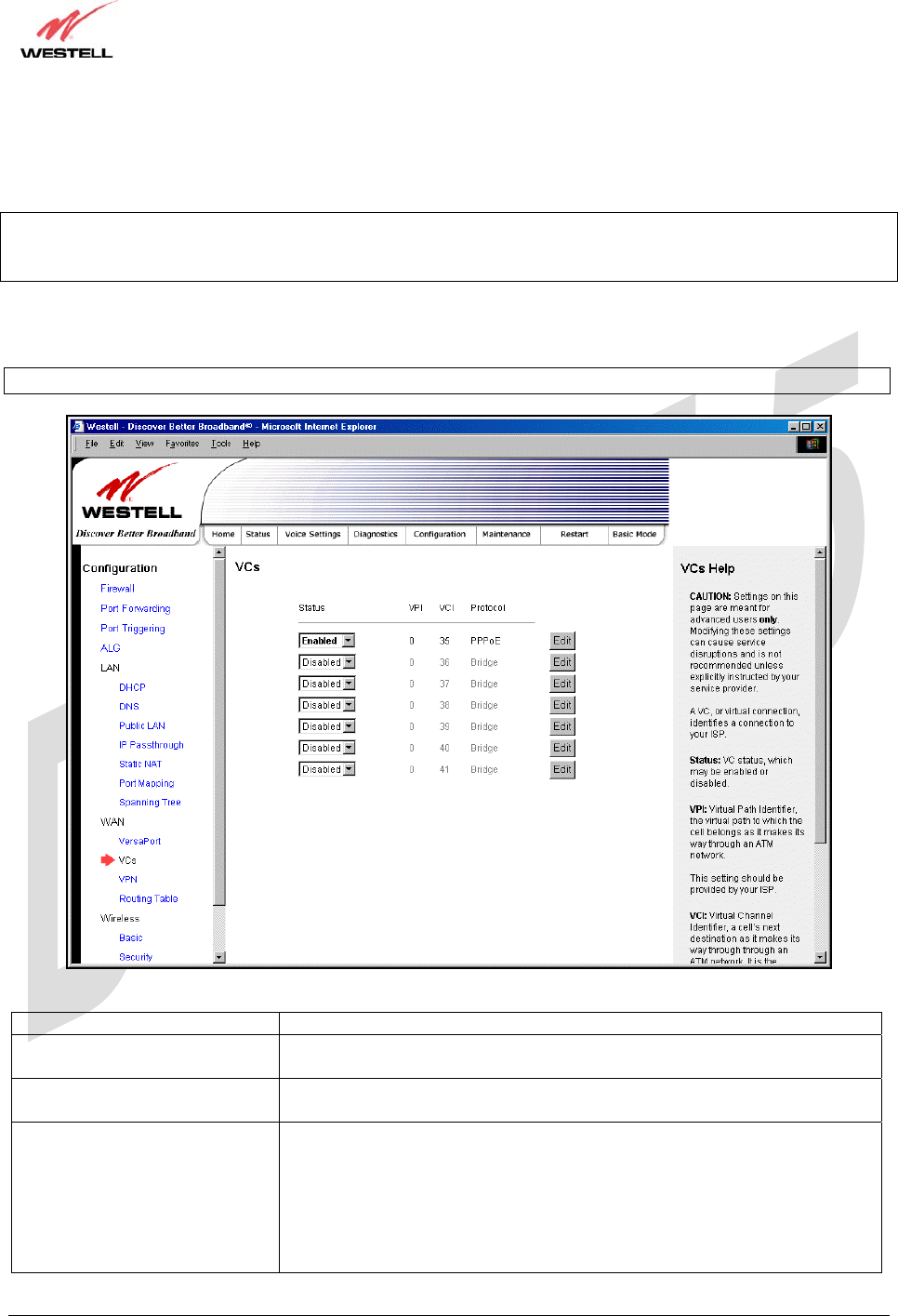
17.7.5 VCs
The following screen will be displayed if you select WAN > VCs from the Configuration screen.
NOTE: In order to enable or edit the VCs, first confirm that your Router is configured for ‘Private LAN’. To
configure your Router for Private LAN, return to the VersaPort screen and select Private LAN. Next, click Save to
save your settings.
The Edit button enables you to change the VC configuration settings of the Router. Details on the edit button are
explained later in this section.
NOTE: The actual information displayed in this screen may vary, depending on the network connection established.
Status Allows you to enable or disable your VC (Virtual Connection)
VPI Displays the VPI (Virtual Path Indicator) value for a particular VC, which is
defined by your Service Provider.
VCI Displays the VCI (Virtual Channel Indicator) value for a particular VC,
which is defined by your Service Provider.
Protocol
NOTE: The configuration
specified by your Service
Provider will determine which
Protocols are available to you.
Displays the Protocol for each VC, which is specified by your Service
Provider.
Possible Response:
PPPoA = Point to Point Protocol over ATM (Asynchronous Transfer Mode)
PPPoE = Point to Point Protocol over Ethernet
Bridge = Bridge Protocol
Routed IP = IP over ATM
TriLink Gateway – Draft 5
030-300445 Rev. A
6/22/05
030-300445 Rev. A 88 June 2005
User Guide TriLink Gateway (Models 427V10, 427V11)
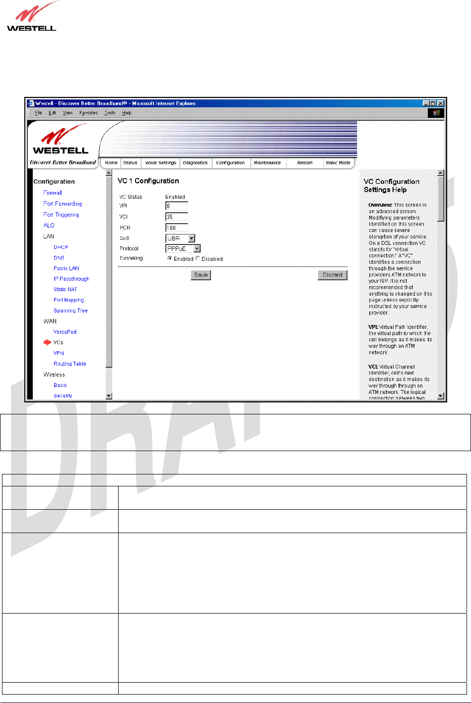
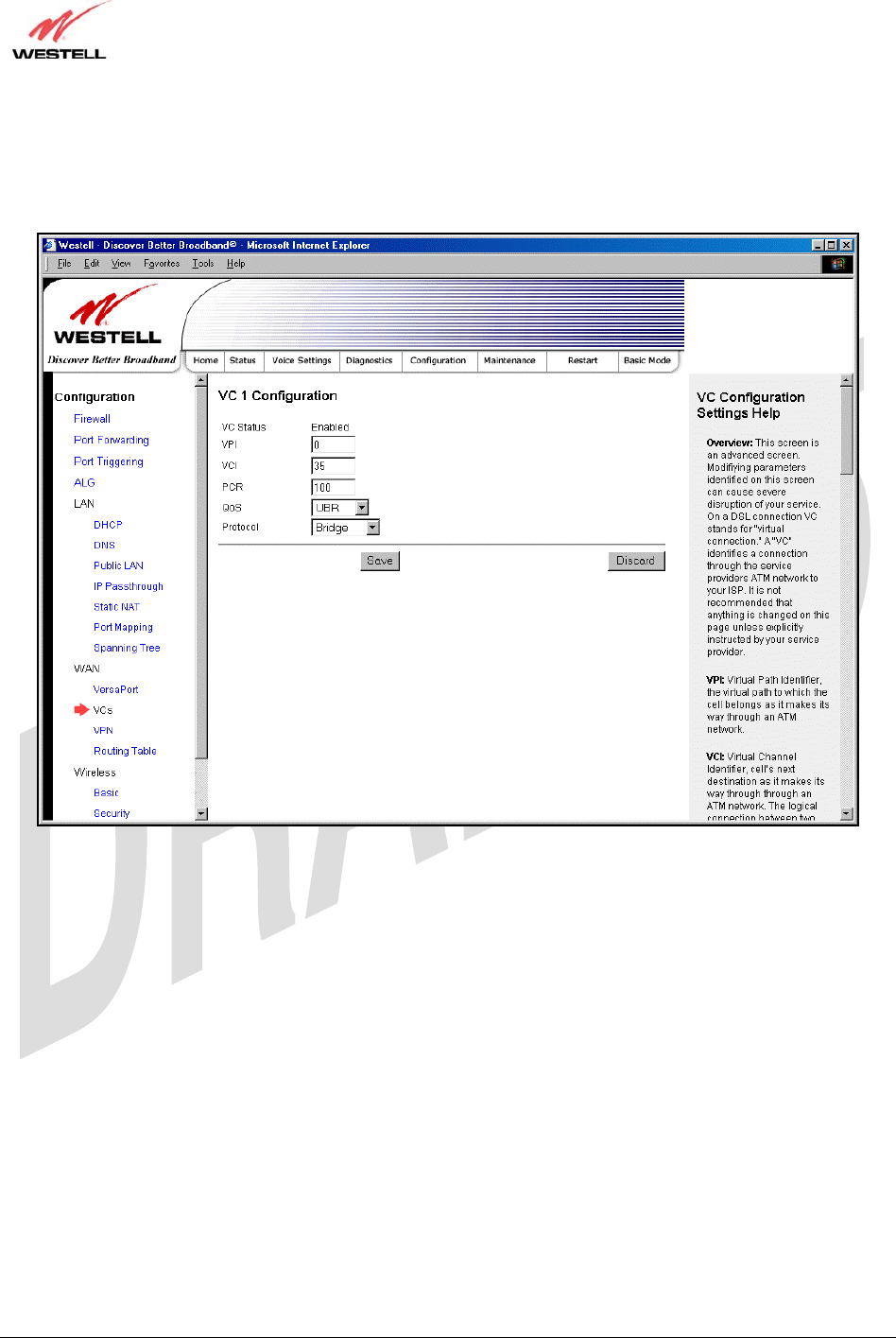
If you click edit in the VCs Configuration screen, the following screen will be displayed. Enter the appropriate
values, and then click Save to save your settings.
NOTE: The values for the IP Address, Gateway, DNS Primary, and DNS Secondary are all “Override of the value
obtained from the PPP connection,” They default to “0.0.0.0,” in which case the override is ignored. Westell
recommends that you do not change the values unless your Internet service provider instructs you to change them.
VC 1 Configuration
VPI This setting allows you to change your VPI (Virtual Path Indicator) value for a
particular VC, which is defined by your Service Provider.
VCI This setting allows you to change your VCI (Virtual Channel Indicator) value for a
particular VC, which is defined by your Service Provider.
PCR Factory Default = 100%
Peak Cell Rate (PCR)-The maximum rate at which cells can be transmitted across a
virtual circuit, specified in cells per second and defined by the interval between the
transmission of the last bit of one cell and the first bit of the next.
This value is a percentage of the current data rate.
100 allows this VC to use 100% of the available bandwidth.
80 allows this VC to use 80% of the available bandwidth.
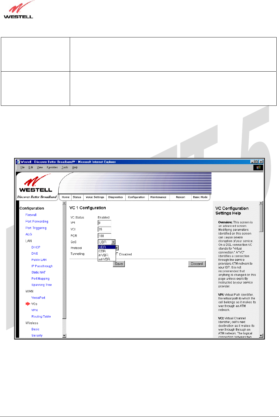
QoS Select the Quality of Service, which is determined by your Service Provider.
Possible Responses:
UBR = Unspecified Bit Rate
CBR = Constant Bit Rate
rt-VBR = real-time Variable Bit Rate
nrt-VBR = non-real-time Variable Bit Rate
Protocol The Protocol for each VC, which is specified by your Service Provider.
TriLink Gateway – Draft 5
030-300445 Rev. A
6/22/05
030-300445 Rev. A 89 June 2005
User Guide TriLink Gateway (Models 427V10, 427V11)
Possible Responses:
PPPoA = Point to Point Protocol over ATM (Asynchronous Transfer Mode)
PPPoE = Point to Point Protocol over Ethernet
Bridge = Bridge Protocol
Routed IP = IP over ATM
Tunneling Factory Default = Enable
If Enabled, this option enables PPP traffic to be bridged to the WAN. This feature
enables you to use a PPPoE shim on the host computer to connect to the Internet
service provider, by bypassing the Router’s capability to do this.
Note: Tunneling is available in PPPoE mode only.
17.7.5.1 Selecting the Quality of Service
To set the Quality of Service, select the desired option from the QoS drop-down menu, and then click Save to save
the settings.
TriLink Gateway – Draft 5
030-300445 Rev. A
6/22/05
030-300445 Rev. A 90 June 2005
User Guide TriLink Gateway (Models 427V10, 427V11)
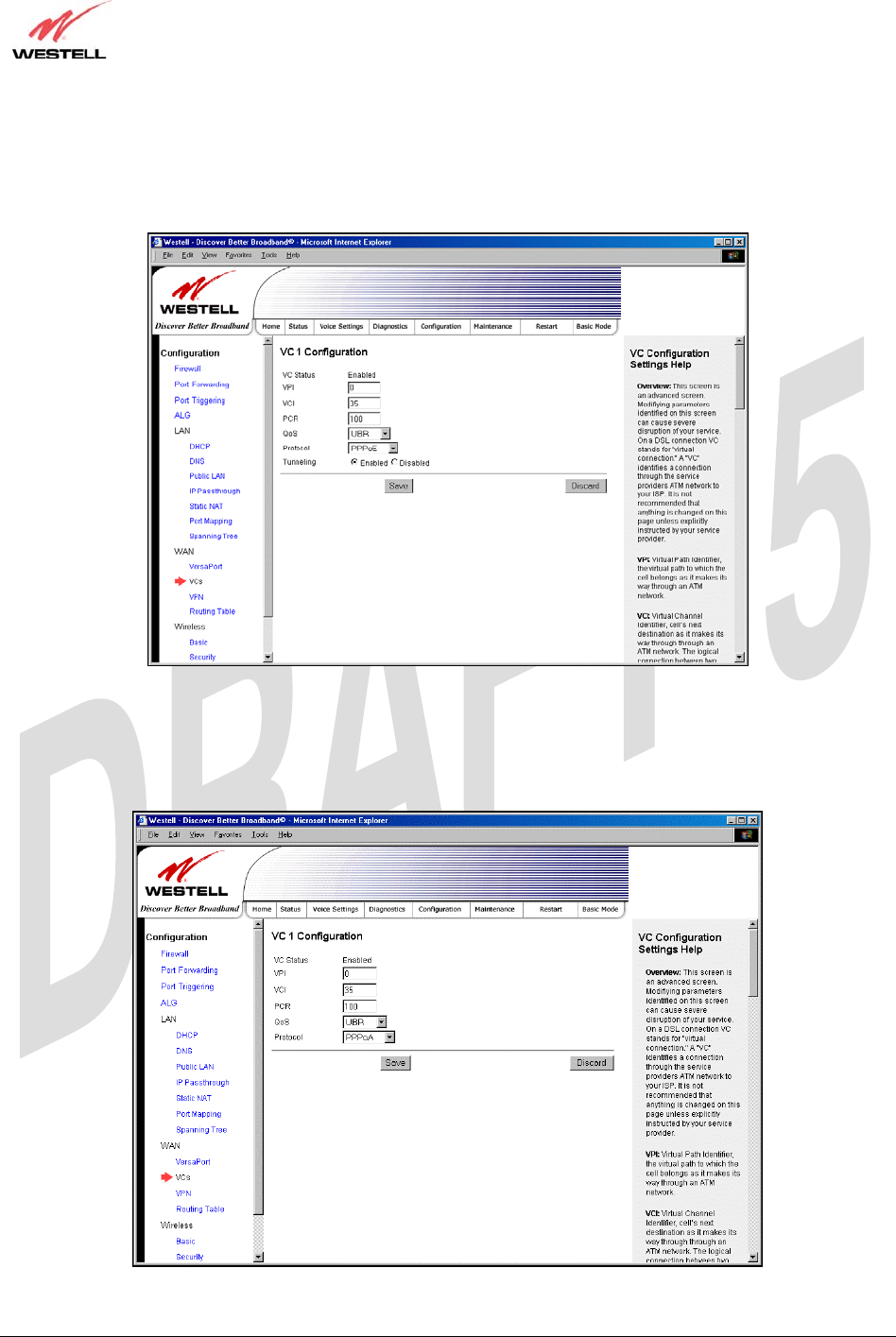
17.7.5.2 Configuring WAN VC Protocol for PPPoE mode
To configure the WAN VC Protocol for PPPoE mode, select PPPoE from the Protocol drop-down menu, the
following screen will be displayed. Enter the appropriate values, and then click save to save your settings.
17.7.5.3 Configuring WAN VC Protocol for PPPoA mode
To configure the WAN VC Protocol for PPPoA mode, select PPPoA from the Protocol drop-down menu, the
following screen will be displayed. Enter the appropriate values, and then click save to save your settings.
TriLink Gateway – Draft 5
030-300445 Rev. A
6/22/05
030-300445 Rev. A 91 June 2005
User Guide TriLink Gateway (Models 427V10, 427V11)
17.7.5.4 Configuring WAN VC Protocol for Bridge mode - (MAC Bridge)
To configure the WAN VC Protocol for Bridge mode, select Bridge from the Protocol drop-down menu, the
following screen will be displayed. Enter the appropriate values, and then click save to save your settings.
TriLink Gateway – Draft 5
030-300445 Rev. A
6/22/05
030-300445 Rev. A 92 June 2005
User Guide TriLink Gateway (Models 427V10, 427V11)
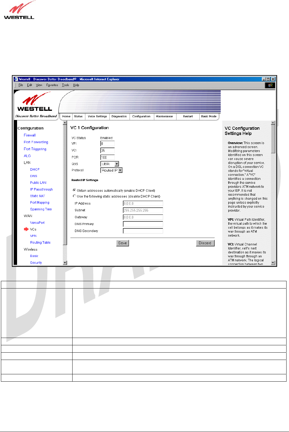
17.7.5.5 Configuring WAN VC Protocol for Routed IP mode
If you select Routed IP from the Protocol drop-down menu, the following screen will be displayed. Enter the
appropriate values, and then click save to save your settings.
VC 1 Routed IP Settings
DHCP Client Factory Default = Enable
If enabled the router will obtain its IP address, gateway address and DNS server
address automatically from the network. If disabled you must manually enter the
information.
Possible Response:
Select Enable to activate the DHCP client.
Select Disable to deactivate the DHCP client.
IP Address Displays the Router’s IP network address.
Subnet Displays the Router’s subnet mask settings.
Gateway Displays the Router’s IP gateway address
DNS Primary Displays the IP address of primary Domain Name Service (DNS) server your router
is using.
DNS Secondary Displays the IP address of secondary DNS server your router is using.
TriLink Gateway – Draft 5
030-300445 Rev. A
6/22/05
030-300445 Rev. A 93 June 2005
User Guide TriLink Gateway (Models 427V10, 427V11)
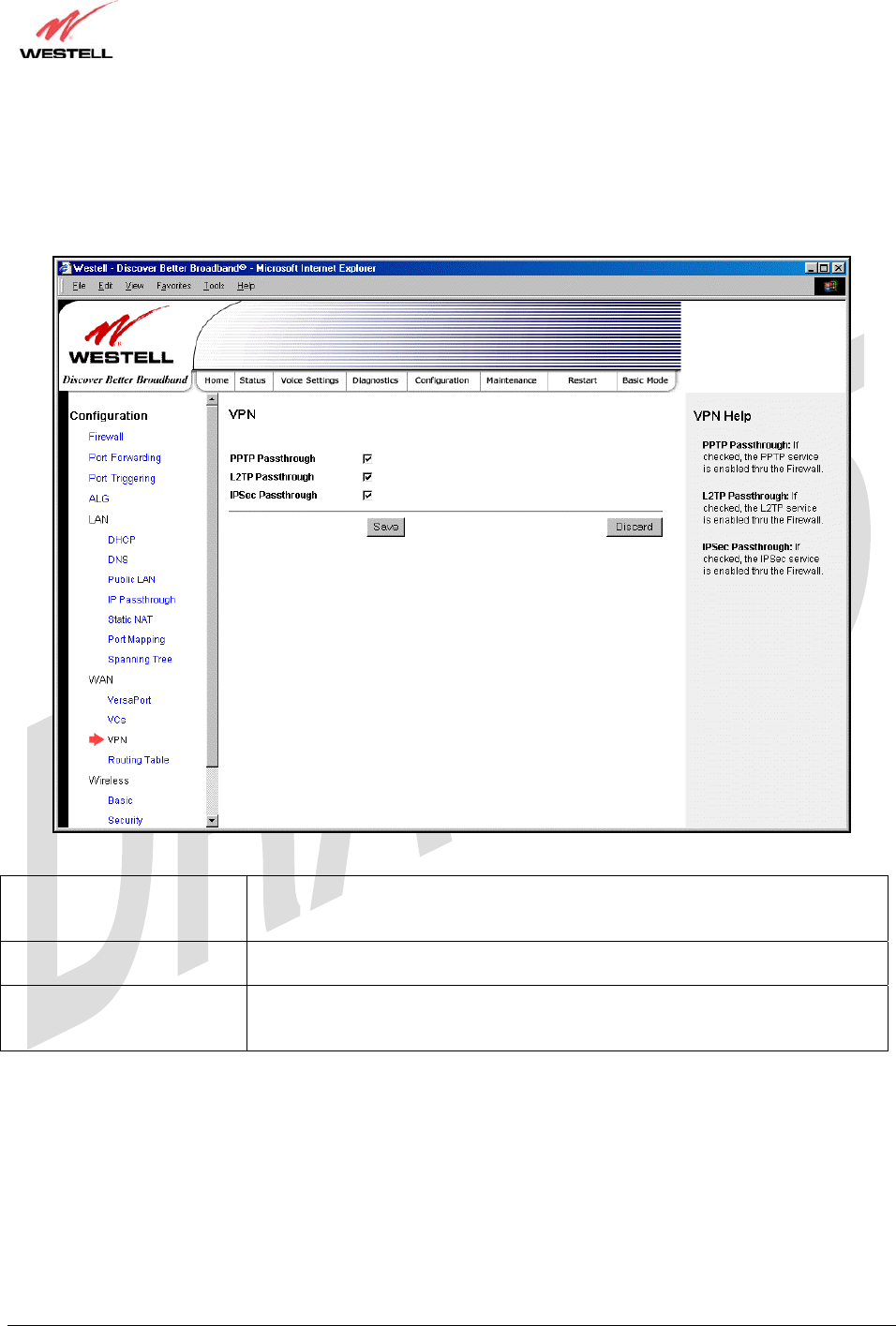
17.7.6 VPN
The following settings will be displayed if you select WAN > VPN from the Configuration menu. Enter the
appropriate values, and then click save to save your settings.
PPTP Passthrough Factory Default = Enabled
If enabled (a check mark will appear in the box), PPTP will work through the
Router’s NAT function.
L2TP Passthrough Factory Default = Enabled
If enabled, IPSec using ESP and L2TP can be supported via an ALG.
IPSec Passthrough Factory Default = Enabled
If enabled, IPSec using ESP can be supported via an ALG. IPSec using AH cannot
be supported through NAT.
TriLink Gateway – Draft 5
030-300445 Rev. A
6/22/05
030-300445 Rev. A 94 June 2005
User Guide TriLink Gateway (Models 427V10, 427V11)
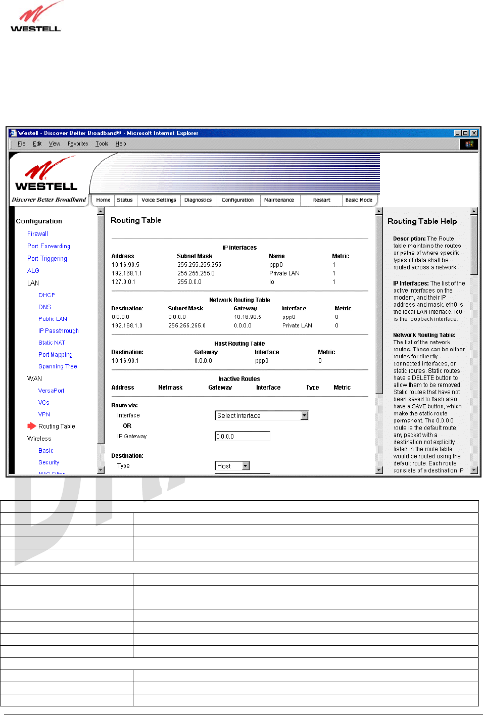
17.7.7 Routing Table
The following settings will be displayed if you select WAN > Routing Table from the Configuration menu. To add
a route to the Network Routing Table, enter the appropriate values, and then click Add Route.
IP Interfaces
Address The IP interface address.
Subnet Mask The IP interface subnet address.
Name The IP interface device name.
Metric
Networking Routing Table
Destination The IP address or subnet of the Route.
Subnet Mask If the Route is a network route, Subnet Mask is used to specify the subnet address.
If the Route is a Host route, then the Host Route check box is used.
Gateway Indicates were to send the packet if it matches this route.
Interface Indicates were to send the packet if it matches this route.
Metric The RIP metric to be assigned to this route if and when it is advertised using RIP.
Rip Indicates whether a static route should be advertised via RIP.
Host Routing Table
Destination
Gateway
Interface
TriLink Gateway – Draft 5
030-300445 Rev. A
6/22/05
030-300445 Rev. A 95 June 2005
User Guide TriLink Gateway (Models 427V10, 427V11)
Metric
RIP
Inactive Routes
Address
Netmask
Gateway
Interface Reference
Route Type
IP Destination
IP Netmask
IP Gateway
Metric
RIP Advertised
Save to Flash
17.8 Wireless Configuration
17.8.1 Basic
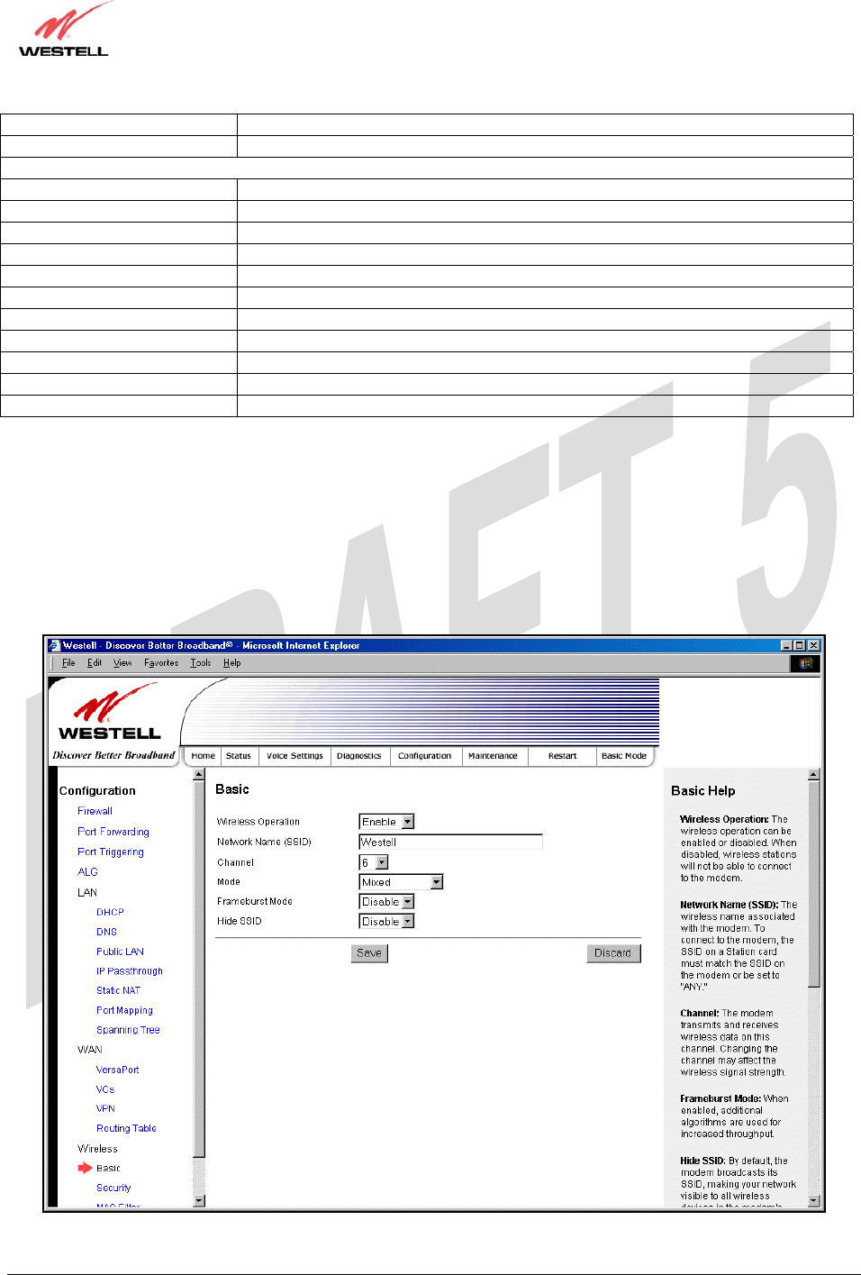
The following settings will be displayed if you select Wireless > Basic from the Configuration menu. Enter the
appropriate values, and then click save to save your settings.

TriLink Gateway – Draft 5
030-300445 Rev. A
6/22/05
030-300445 Rev. A 96 June 2005
User Guide TriLink Gateway (Models 427V10, 427V11)
Wireless Basic Configuration
Wireless Operation Factory Default = Enabled
When disabled, no wireless stations will be able to connect to the Router.
Network Name (SSID) Factory Default = Westell
This string (32 characters or less) is the name associated with the AP. To connect
to the AP, the SSID on a Station card must match the SSID on the AP card or be
set to “ANY.”
Channel Factory Default = 6
The AP transmits and receives data on this channel. The number of channels to
choose from is pre-programmed into the AP card. Station cards do not have to be
set to the same channel as the AP; the Stations scan all channels and look for an
AP to connect to.
Possible Response:
1 through 11
Mode Factory Default = Mixed
This setting allows station to communicate with the Router.
Possible Response:
Mixed: Station using any of the 802.11b, 802.11b+, and 802.11g rates can
communicate with the Router.
Legacy Mixed: Same as Mixed, but also allows older 802.11b cards to
communicate with the Router.
11b only: Communication with the Router is limited to 802.11b
11g only: Communication with the Router is limited to 802.11g
Frameburst Mode Factory Default = Disable
If enabled, additional algorithms are used for increased throughput.
Hide SSID Factory Default = Disable
If enabled, the Router will not broadcast the SSID. To connect to the Router, each
Station must configure its SSIDs so that it matches the Router’s Network Name
(SSID).
TriLink Gateway – Draft 5
030-300445 Rev. A
6/22/05
030-300445 Rev. A 97 June 2005
User Guide TriLink Gateway (Models 427V10, 427V11)
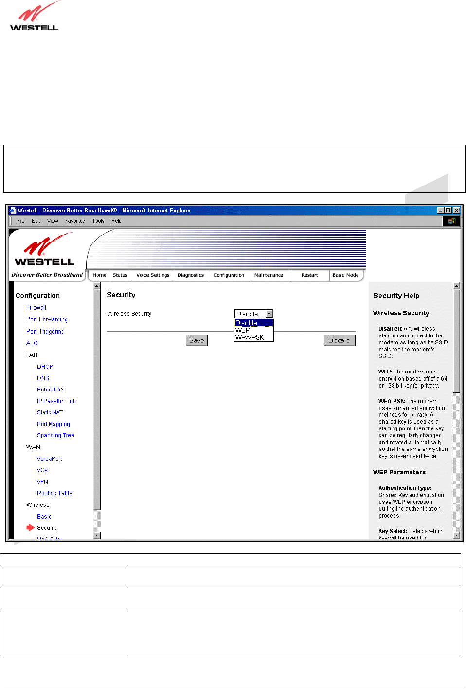
17.8.2 Wireless Security
The following screen will be displayed if you select Wireless > Security from the Configuration menu. Select the
desired security option from the Wireless Security drop-down menu. After you configured your wireless security
settings, click Save to save the settings.
IMPORTANT: Client PCs can use any Wireless Fidelity (Wi-Fi) 802.11b/g/g+ certified card to communicate with
the Router. The Wireless card and Router must use the same security code type. If you use WPA-PSK or WEP
wireless security, you must configure your computer’s wireless adapter for the security code that you use. You
can access the settings in the advanced properties of the wireless network adapter.
Wireless Security
Disable Factory Default = Disable
If Disable is selected, wireless security will not be activated on your Router.
WEP Selecting WEP enables you set up Wired Equivalent Privacy (WEP) on your
Router. WEP uses encryption based on a 64- or 128-bit key for privacy.
WPA-PSK Selecting WPA-PSK enables you set up Wi-Fi Protected Access-Pre-Shared Key
on your Router. WPA-PSK uses enhanced encryption methods for privacy. A
shared key is used as a starting point, and then the key can be regularly changed
and rotated automatically so that the same encryption key is never used twice.
TriLink Gateway – Draft 5
030-300445 Rev. A
6/22/05
030-300445 Rev. A 98 June 2005
User Guide TriLink Gateway (Models 427V10, 427V11)
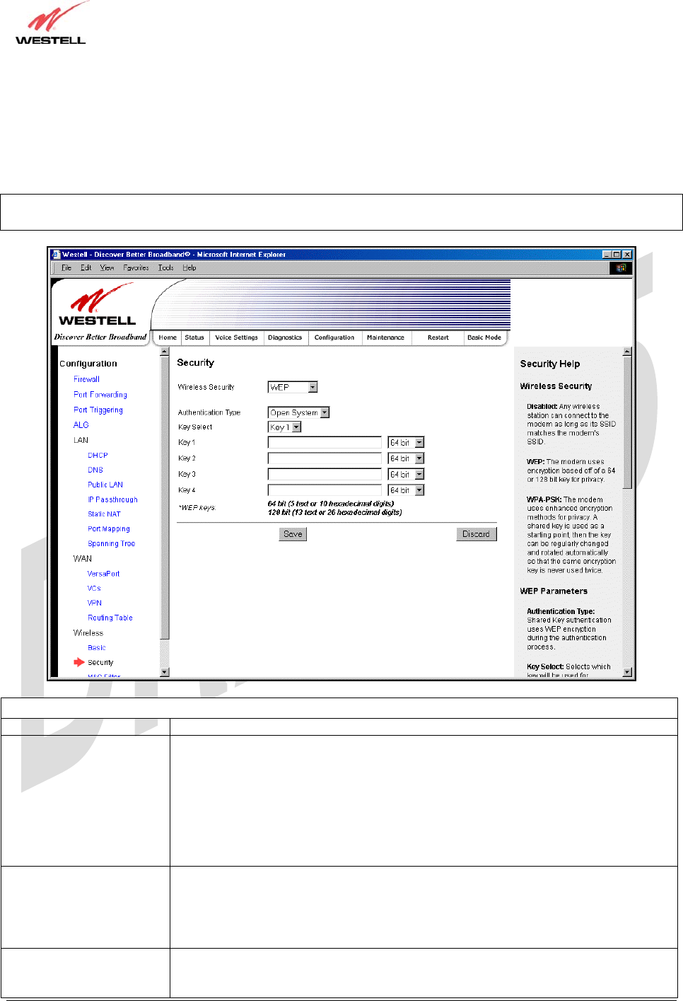
17.8.2.1 Enabling WEP Security
If you select WEP from the Wireless Security drop-down menu, the following screen will be displayed. Enter the
appropriate values, and then click Save to save the settings.
NOTE: The WEP key must be 64 bit (5 text characters or 10 hexadecimal digits in length) or 128 bit (13 text
characters or 26 hexadecimal digits in length).
Wireless Security (WEP)
Wireless Security WEP has been selected.
Authentication Type Factory Default = Open System
Possible Response:
Open System: Open System authentication allows any station to associate with the
wireless network but only stations with the valid WEP key can send or receive data
from the router. Open System authentication is considered to be more secure than
Shared Key authentication.
Shared Key: Shared Key authentication requires the station to authenticate with the
router using the WEP key before it can associate with the wireless network.
Key Select Factory Default = Key 1
Selects which WEP key the router should use.
NOTE: The WEP key must be the same value and type for both the Router and the
wireless network adapter.
Key 1
To
Key 4
Select the length of the WEP key from the pull down menu and enter key WEP Key in
the box. A 64-bit key must be either 5 text characters or 10 hexadecimal characters. A
128-
b
it ke
y
must be 13 text characters or 26 hexadecimal characters. The onl
y
TriLink Gateway – Draft 5
030-300445 Rev. A
6/22/05
030-300445 Rev. A 99 June 2005
User Guide TriLink Gateway (Models 427V10, 427V11)
allowable hexadecimal characters are 0-9 and A-F.
NOTE: The WEP key must be the same value and type for both the Router and the
wireless network adapter.
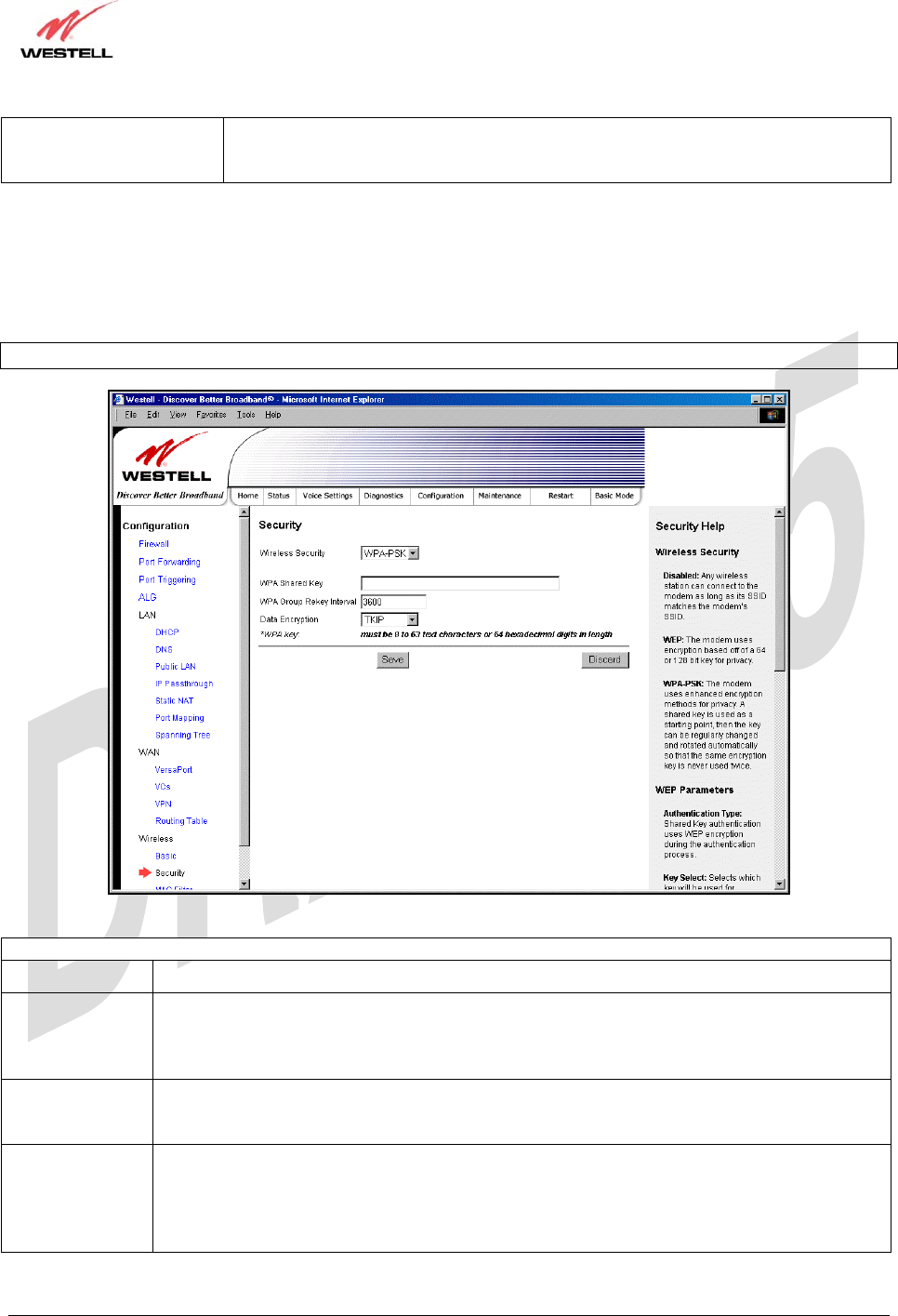
17.8.2.2 Enabling WPA-PSK Security
If you select WPA-PSK from the Wireless Security drop-down menu, the following screen will be displayed. Enter
the appropriate values, and then click Save to save the settings.
NOTE: The WPA key must be 8 to 63 characters or 64 hexadecimal digits in length.
Wireless Security (WPA-PSK)
Wireless Security WPA-PSK has been selected.
WPA Shared
Key This is a passphrase (also called a shared secret) that must be entered in both the wireless router
and the wireless client. This shared secret can be between 8 to 63 text characters and can
include special characters and spaces. The more random your WPA Shared Key, the more
secure it is.
WPA Group
Rekey Interval Factory Default = 3600
The number of seconds between rekeying the WPA group key. Zero “0” means that rekeying is
disabled.
Data Encryption Factory Default = TKIP
Possible Respone:
TKIP- Selecting this option enables the Temporal Key Integrity Protocol for data encryption.
AES- Selecting this option enables the Advanced Encryption Standard for data encryption.
TKIP/AES- Selecting this option enables the Router to accept either TKIP or AES encryption
TriLink Gateway – Draft 5
030-300445 Rev. A
6/22/05
030-300445 Rev. A 100 June 2005
User Guide TriLink Gateway (Models 427V10, 427V11)
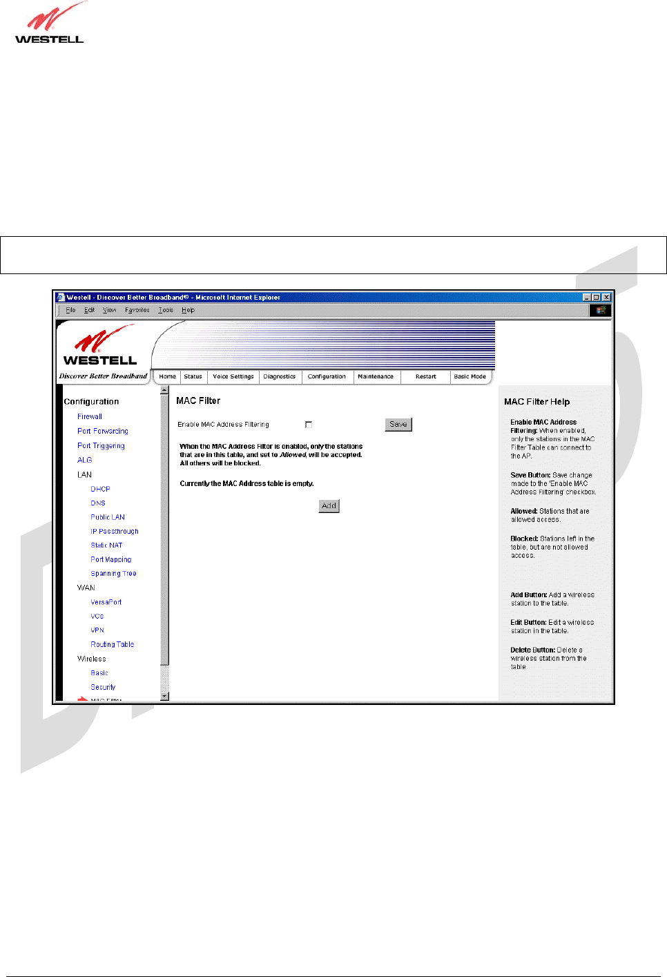
17.8.3 MAC Filter
The following settings will be displayed if you select Wireless > MAC Filter from the Configuration menu. This
screen enables you to configure the MAC filter settings for your Router.
After you have finished adding, editing or deleting MAC addresses from the MAC Filter table (as explained in the
following paragraphs), click the box adjacent to Enable MAC Address Filtering (a check mark will appear in the
box), and then click Save to save your settings.
NOTE: When the MAC address Filter is enabled (box is checked), only the stations that are in the MAC Filter table
and that are set to Allowed will be accepted by the Router. All other stations will be blocked.
TriLink Gateway – Draft 5
030-300445 Rev. A
6/22/05
030-300445 Rev. A 101 June 2005
User Guide TriLink Gateway (Models 427V10, 427V11)
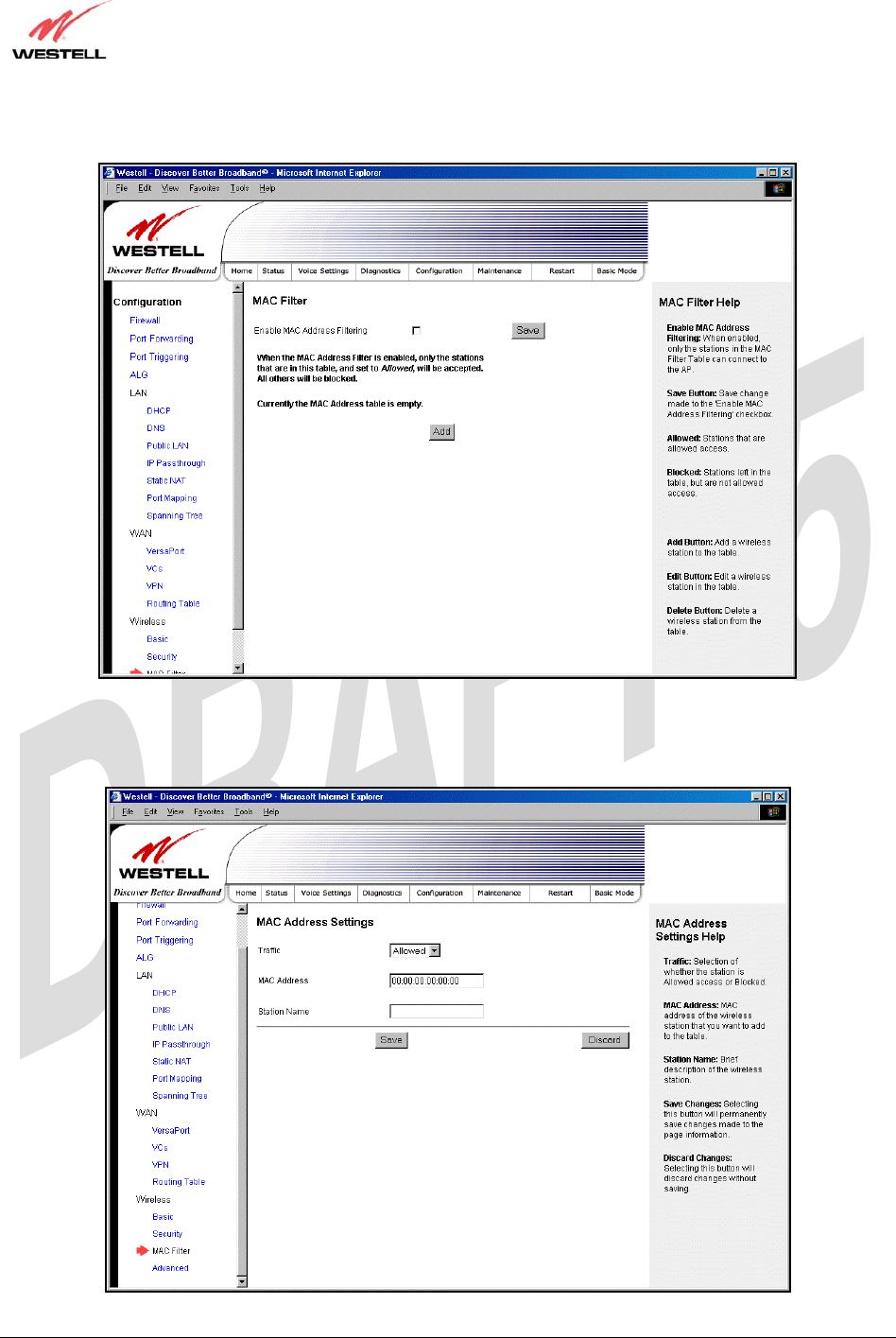
To add stations to the MAC Address table, click the add button.
If you clicked add, the following screen will be displayed. Enter the appropriate values in the fields provided, and
then click Save to save your settings.
TriLink Gateway – Draft 5
030-300445 Rev. A
6/22/05
030-300445 Rev. A 102 June 2005
User Guide TriLink Gateway (Models 427V10, 427V11)
MAC Address Settings
Traffic Factory Default = Allowed
If Blocked is selected, the station will be blocked (it cannot access the Router).
MAC Address Factory Default = 00:00:00:00:00:00
The MAC address of the wireless station you want to add.
Station Name The name of the wireless station you want to add.
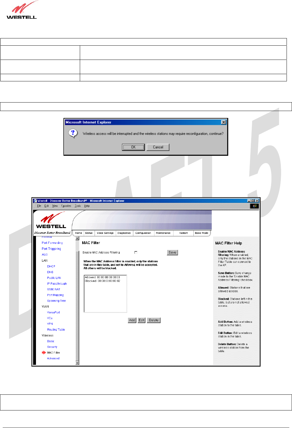
If you clicked Save, the following pop-up screen will be displayed. Click OK to continue.
NOTE: Wireless access will be interrupted and the wireless stations may require reconfiguration.
If you clicked OK, in the preceding pop-up screen, the following screen will be displayed. The screen displays the list
of MAC addresses added to the MAC Address Filter Table. You may now add, edit, or delete MAC addresses from
the table by clicking on the desired MAC address (displayed in the window) and then by clicking either Add, Edit, or
Delete. Next, click OK in the pop-up screen.
After you have finished adding, editing or deleting MAC addresses in the MAC Filter table, click the box adjacent to
Enable MAC Address Filtering (a check mark will appear in the box). Click Save to save your settings.
NOTE: When the MAC address Filter is enabled (box is checked), only the stations that are in MAC Filter table and
that are set to Allowed will be accepted by the Router. All other stations will be blocked.
TriLink Gateway – Draft 5
030-300445 Rev. A
6/22/05
030-300445 Rev. A 103 June 2005
User Guide TriLink Gateway (Models 427V10, 427V11)
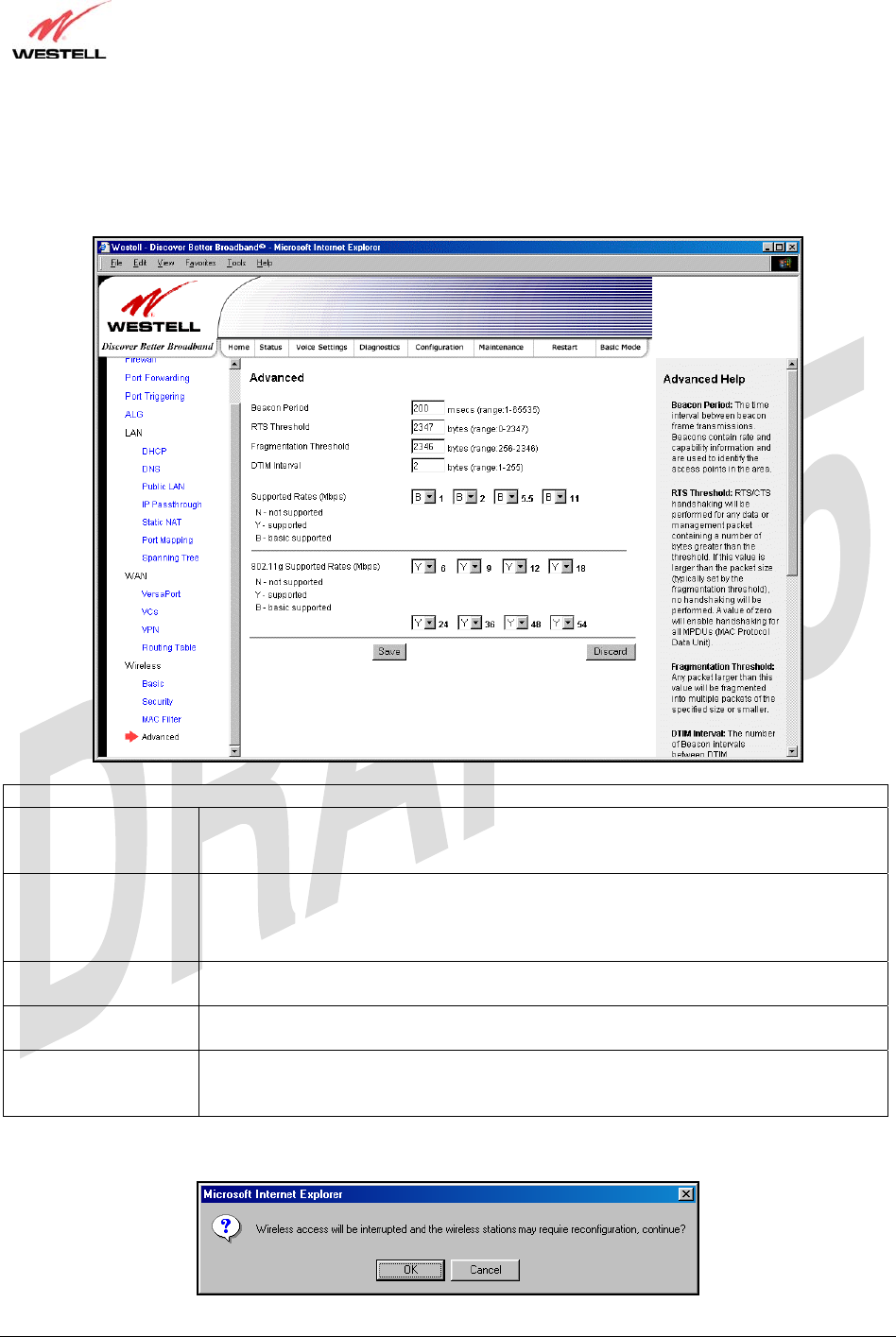
17.8.4 Advanced Wireless Settings
The following settings will be displayed if you select Wireless > Advanced from the Configuration menu. Enter the
appropriate values, and then click save to save the settings.
Wireless Advanced Configuration
Beacon Period The time interval between beacon frame transmissions. Beacons contain rate and
capability information. Beacons received by stations can be used to identify the access
points in the area.
RTS Threshold RTS/CTS handshaking will be performed for any data or management MPDU
containing a number of bytes greater than the threshold. If this value is larger than the
MSDU size (typically set by the fragmentation threshold), no handshaking will be
performed. A value of zero will enable handshaking for all MPDUs.
Fragmented Threshold Any MSDU or MPDU larger than this value will be fragmented into an MPDU of the
specified size.
DTIM Interval The number of Beacon intervals between DTIM transmissions. Multicast and broadcast
frames are delivered after every DTIM
Supported Rates
802.11b Rates (Mbps)
802.11g Rates (Mbps)
These are the allowable communication rates that the Router will attempt to use. The
rates are also broadcast within the connection protocol as the rates supported by the
Router.
If you clicked save, the following pop-up screen will be displayed. Click OK to continue.
TriLink Gateway – Draft 5
030-300445 Rev. A
6/22/05
030-300445 Rev. A 104 June 2005
User Guide TriLink Gateway (Models 427V10, 427V11)
18. MAINTENANCE
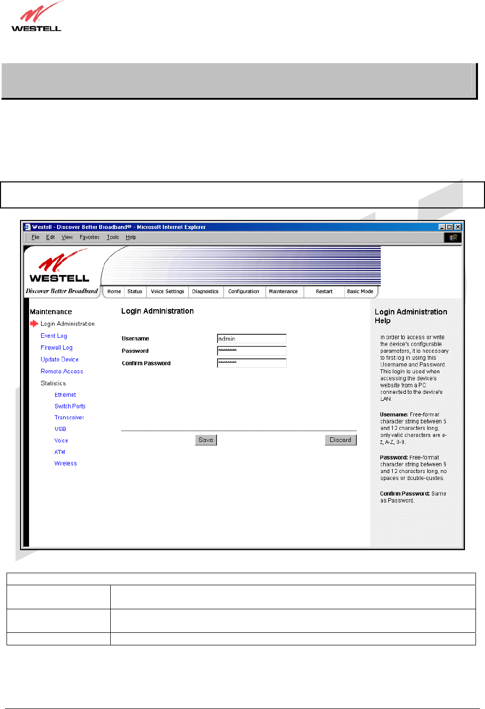
18.1 Login Administration
The following screen will be displayed if you select Admin Password from the Maintenance menu. Enter the
appropriate values, and then click save to save the settings.
Note: Password must be at least 6 characters and must not exceed 12 characters long. Alphanumeric values are
permitted. The Password and Confirm Password fields are masked with “*” for security measures.
Login Administration
Username The administrator’s username. This is a free-format character string between 5 and 12
characters long, no spaces.
Password The administrator’s password. This is a free-format character string between 6 and 12
characters long, no spaces.
Confirm Password The identical value that was entered in the password field.
TriLink Gateway – Draft 5
030-300445 Rev. A
6/22/05
030-300445 Rev. A 105 June 2005
User Guide TriLink Gateway (Models 427V10, 427V11)
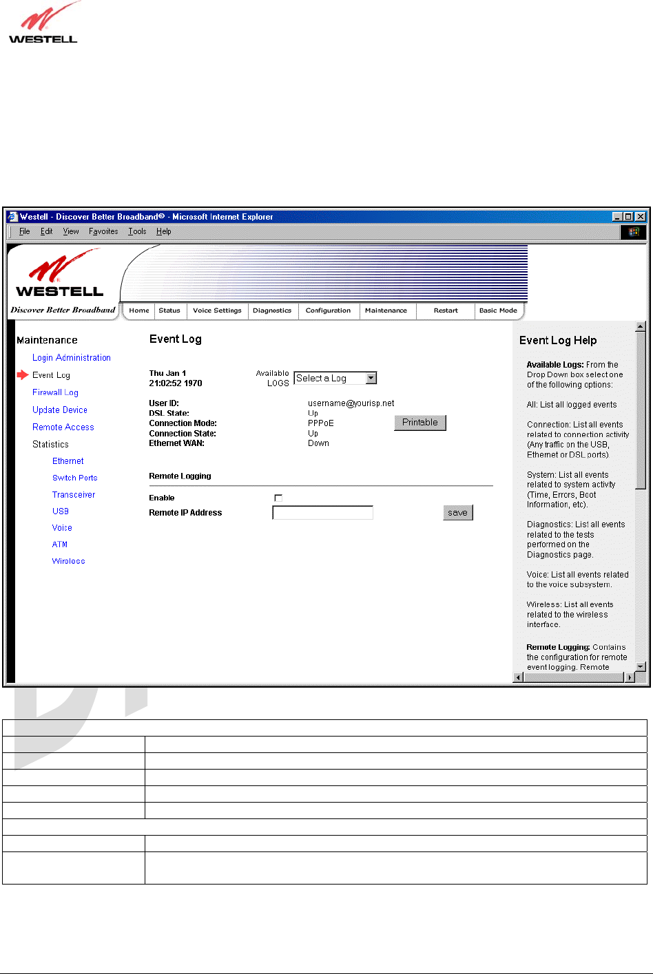
18.2 Event Log
The following screen will be displayed if you select Event Log from the Maintenance menu. The Remote Logging
function enables event logs to be sent to a machine running a syslog server. To enable Remote Logging, click the box
adjacent to Enable (a check mark will appear in the box) and then enter an IP address in the Remote IP Address
field. Click Save to save your settings.
Event Log
User ID The name of your connection.
DSL State The state of the DSL connection.
Connection Mode The mode of connection used to connect to your ISP.
Connection State The state of the PPP connection.
Ethernet WAN The state of the Ethernet WAN connection.
Remote Logging
Enable Enables remote logging of Event Logs
Remote IP Address The IP address of the syslog server machine on the local area network to which the
Event Logs are sent.
TriLink Gateway – Draft 5
030-300445 Rev. A
6/22/05
030-300445 Rev. A 106 June 2005
User Guide TriLink Gateway (Models 427V10, 427V11)
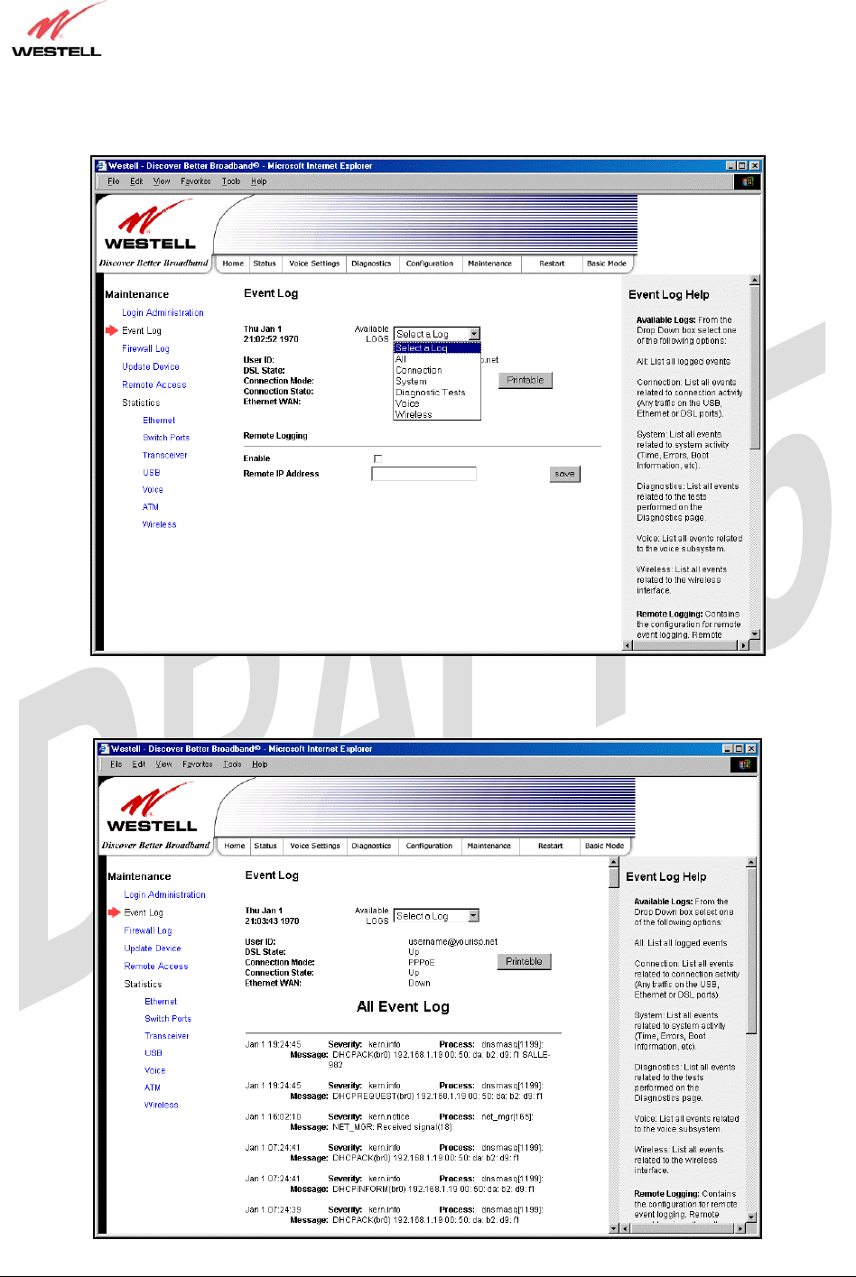
To view logged events, select an option from the Available LOGS drop-down menu.
If you select All, the following screen will be displayed. To obtain a printable version of the Event logs, click on
Printable.
TriLink Gateway – Draft 5
030-300445 Rev. A
6/22/05
030-300445 Rev. A 107 June 2005
User Guide TriLink Gateway (Models 427V10, 427V11)
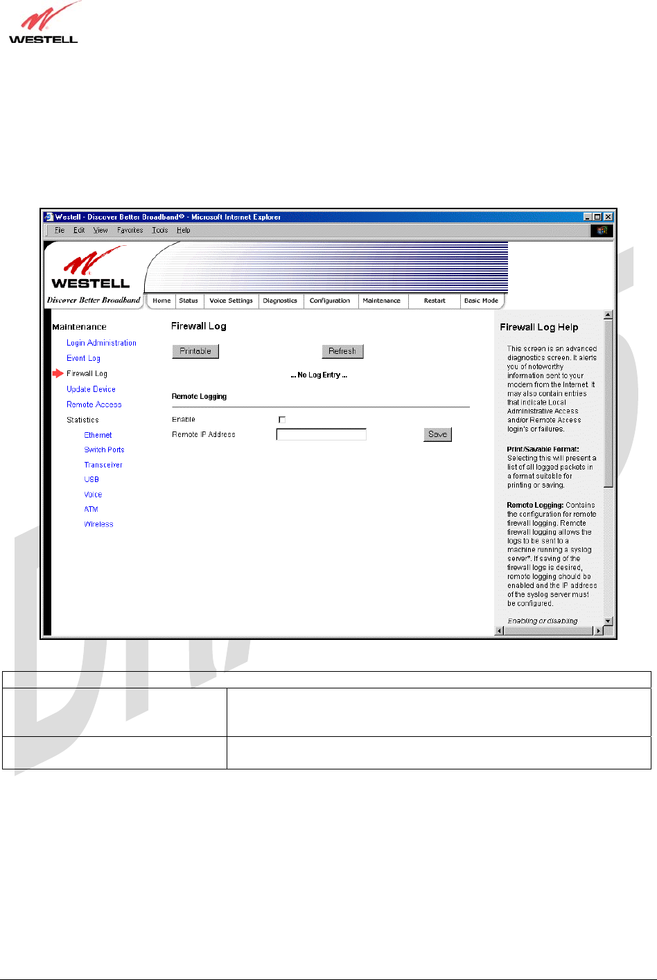
18.3 Firewall Log
The following screen will be displayed if you select Firewall Log from the Maintenance menu. To obtain a
printable version of the Event logs, click on Printable. Click on Refresh to refresh the screen. To enable Remote
Logging, click the box adjacent to Enable (a check mark will appear in the box) and then enter an IP address in the
Remote IP Address field. Click Save to save your settings.
Remote Logging
Enable Factory Default = Disable
If enabled (a check mark will appear in the box), the Router will send
firewall logs to a syslog server.
Remote IP Address The IP address of the syslog server machine to which the diagnostics logs
to be sent.
TriLink Gateway – Draft 5
030-300445 Rev. A
6/22/05
030-300445 Rev. A 108 June 2005
User Guide TriLink Gateway (Models 427V10, 427V11)
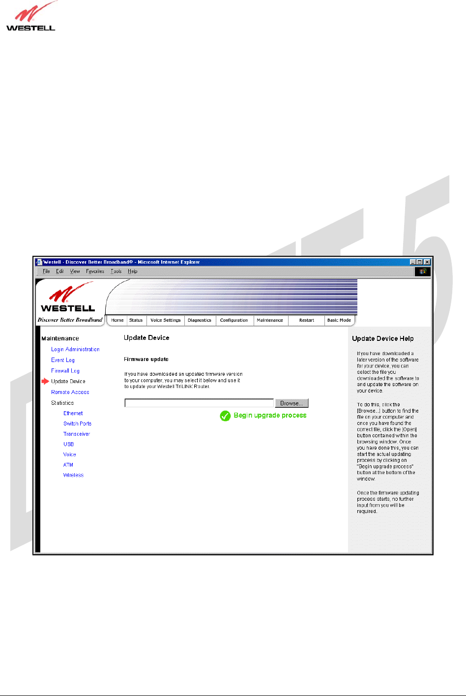
18.4 Update Device
The following screen will be displayed if you select Update Device from the Maintenance menu. This screen
enables you to identify the version of software in your device. You can also update the software in your device to the
latest version supported.
To update your modem to the latest software version supported, perform the following steps:
1. Download the update file and store it to a location on your PC.
2. Click the Browse button in the Update Modem screen, and then navigate to the update file stored on your PC.
3. Click on the update file and then click Open. The path to the update file will appear in the Browse bar.
4. Click Begin upgrade process to begin the software update for your modem.
5. After your modem has been updated, wait a brief moment for the modem to reset and establish a DSL sync.
6. Confirm that the DSL LED on your modem is solid green before continuing your modem’s configuration.
TriLink Gateway – Draft 5
030-300445 Rev. A
6/22/05
030-300445 Rev. A 109 June 2005
User Guide TriLink Gateway (Models 427V10, 427V11)
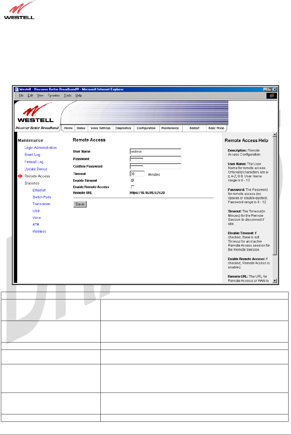
18.5 Remote Access
The following screen will be displayed if you select Remote Access from the Maintenance menu. This screen
enables you to configure Remote Access for your Router. Enter the appropriates values in the fields provided and
then click Save to save the settings.
Remote Access
User Name The name used for Remote Access session. The only valid characters are
(a-z, A-Z, 0-9). The User Name must be at least 6 characters and must
not exceed 12 characters long.
Password The password used for Remote Access session. Do not use spaces or
double-quotes in the password. The password must be at least 6
characters and must not exceed 12 characters long.
Confirm Password Enter the same values as the password.
Timeout The interval (in minutes) after which the Remote Access session will
disconnect, if it is idle.
Enable Timeout Factory Default = Enable
If Enabled (box is checked) this will activate the Remote Access timeout
function.
If Disabled, the Remote Access timeout function will be deactivated.
Enable Remote Access Factory Default = Disable
If Enabled (box is checked), Remote Access will be activated.
If Disabled, Remote Access will be deactivated.
Remote URL The URL for the Remote Access session.
TriLink Gateway – Draft 5
030-300445 Rev. A
6/22/05
030-300445 Rev. A 110 June 2005
User Guide TriLink Gateway (Models 427V10, 427V11)
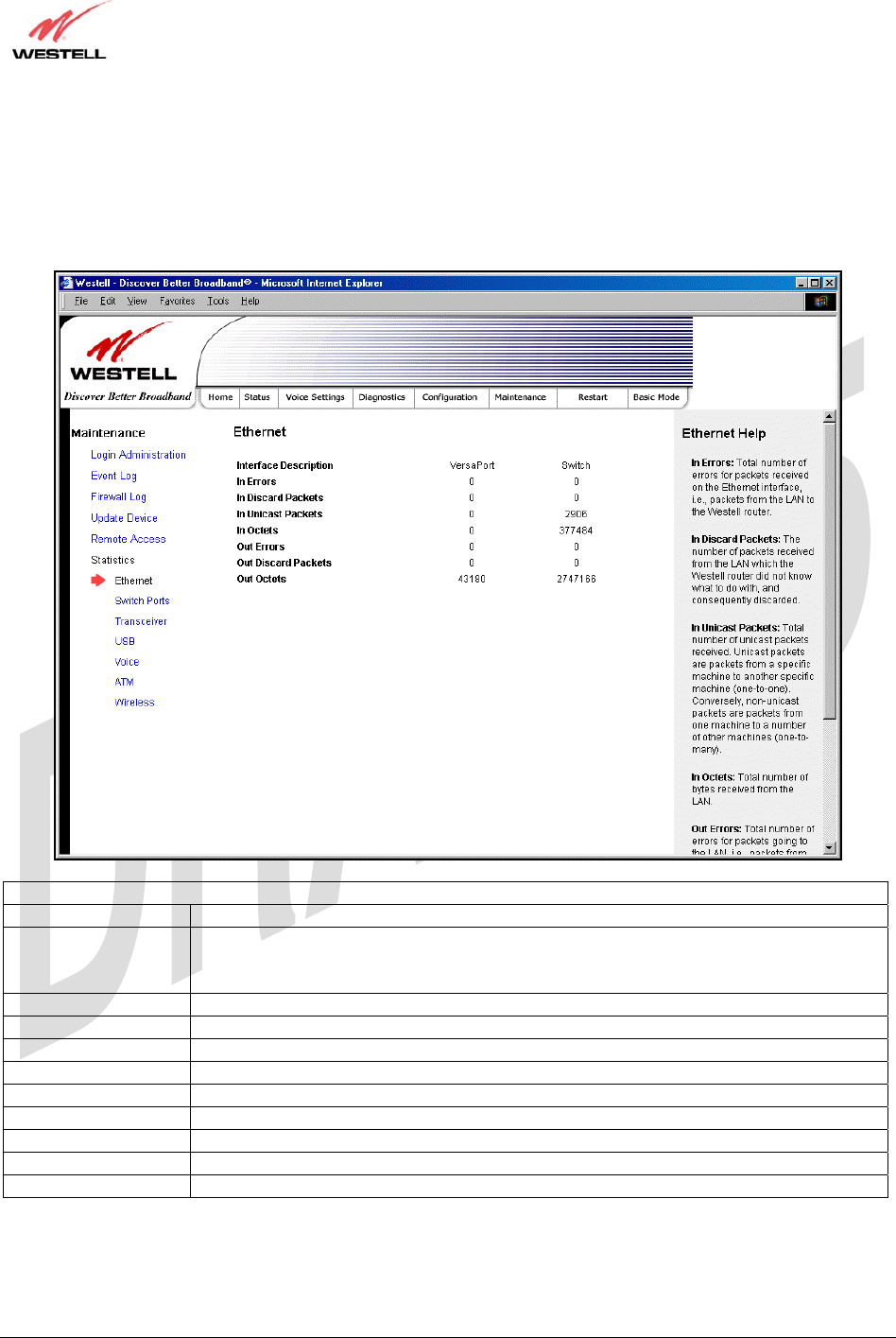
18.6 Statistics
18.6.1 Ethernet Port Statistics
The following settings will be displayed if you select Ethernet from the Statistics menu.
Ethernet Port Statistics
Interface Description The description of the Ethernet interface on the Router.
VersaPort The VersaPort™2 on the rear of the Router. Note: When VersaPort is configured for
Private LAN mode via the modem’s VersaPort configuration screen, section 17.7.1,
VersaPort™2 functions as a fifth Ethernet switch, (E5).
Switch The Ethernet ports (E1, E2, E3, E4). Each functions as an Ethernet switch on the Router.
In Errors The number of error packets received on the Ethernet interface.
In Discard Packets The number of discarded packets received.
In Unicast Packets The number of Unicast packets received on the Ethernet interface.
In Octets The number of bytes received on the Ethernet interface.
Out Errors The number of outbound packets that could not be transmitted due to errors.
Out Discard Packets The number of outbound packets discarded.
Out Unicast Packets The number of Unicast packets transmitted on the Ethernet interface.
Out Octets The number of bytes transmitted on the Ethernet interface.
TriLink Gateway – Draft 5
030-300445 Rev. A
6/22/05
030-300445 Rev. A 111 June 2005
User Guide TriLink Gateway (Models 427V10, 427V11)
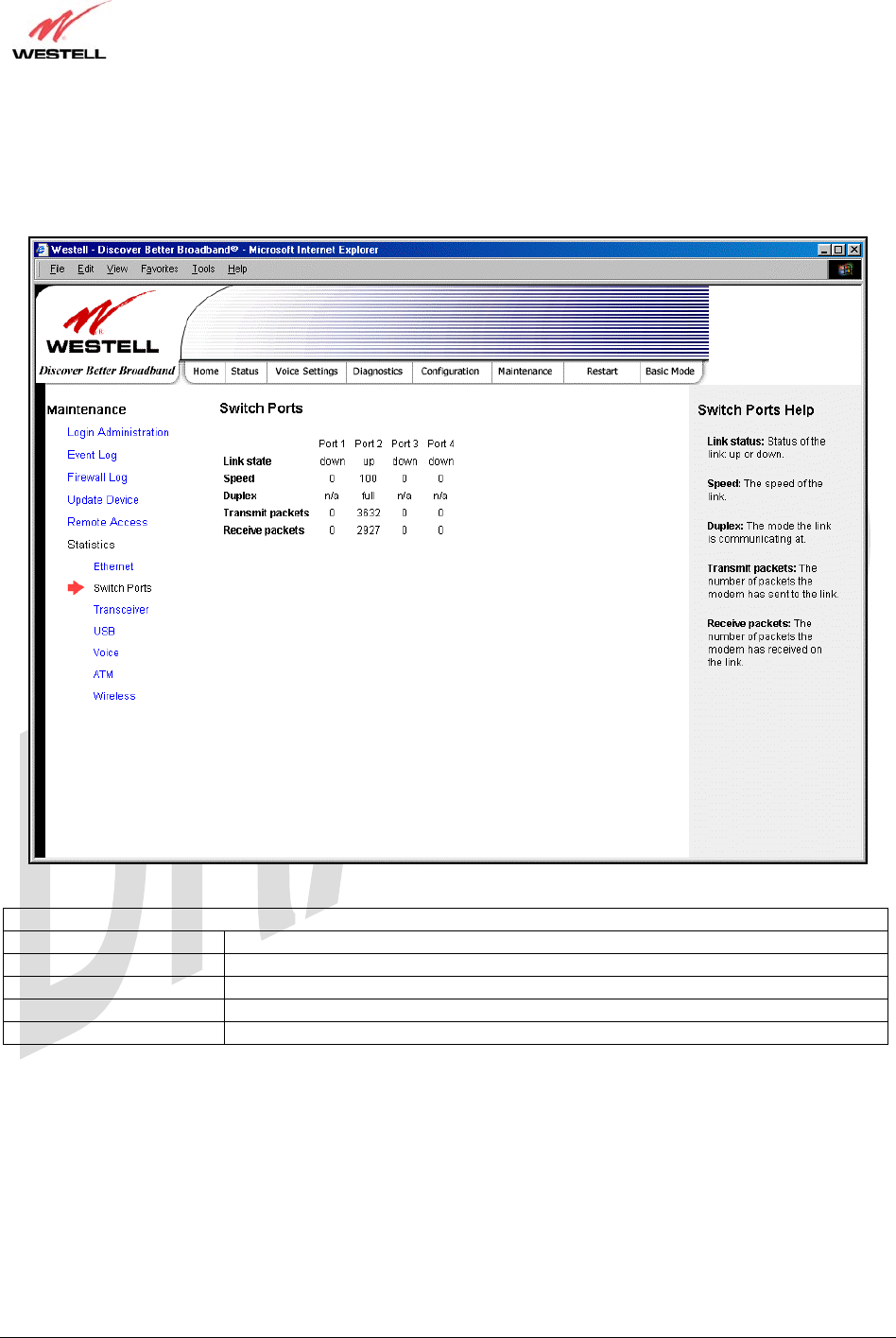
18.6.2 Switch Ports Statistics
The following settings will be displayed if you select Switch Ports from the Statistics menu.
Switch Ports Statistics
Link State The status of the switch port.
Speed The negotiated speed of the Ethernet link.
Duplex The communication mode of the switch port.
Transmit Packets The number of Ethernet packets transmitted from this port
Receive Packets The number of Ethernet packets received on this port.
TriLink Gateway – Draft 5
030-300445 Rev. A
6/22/05
030-300445 Rev. A 112 June 2005
User Guide TriLink Gateway (Models 427V10, 427V11)
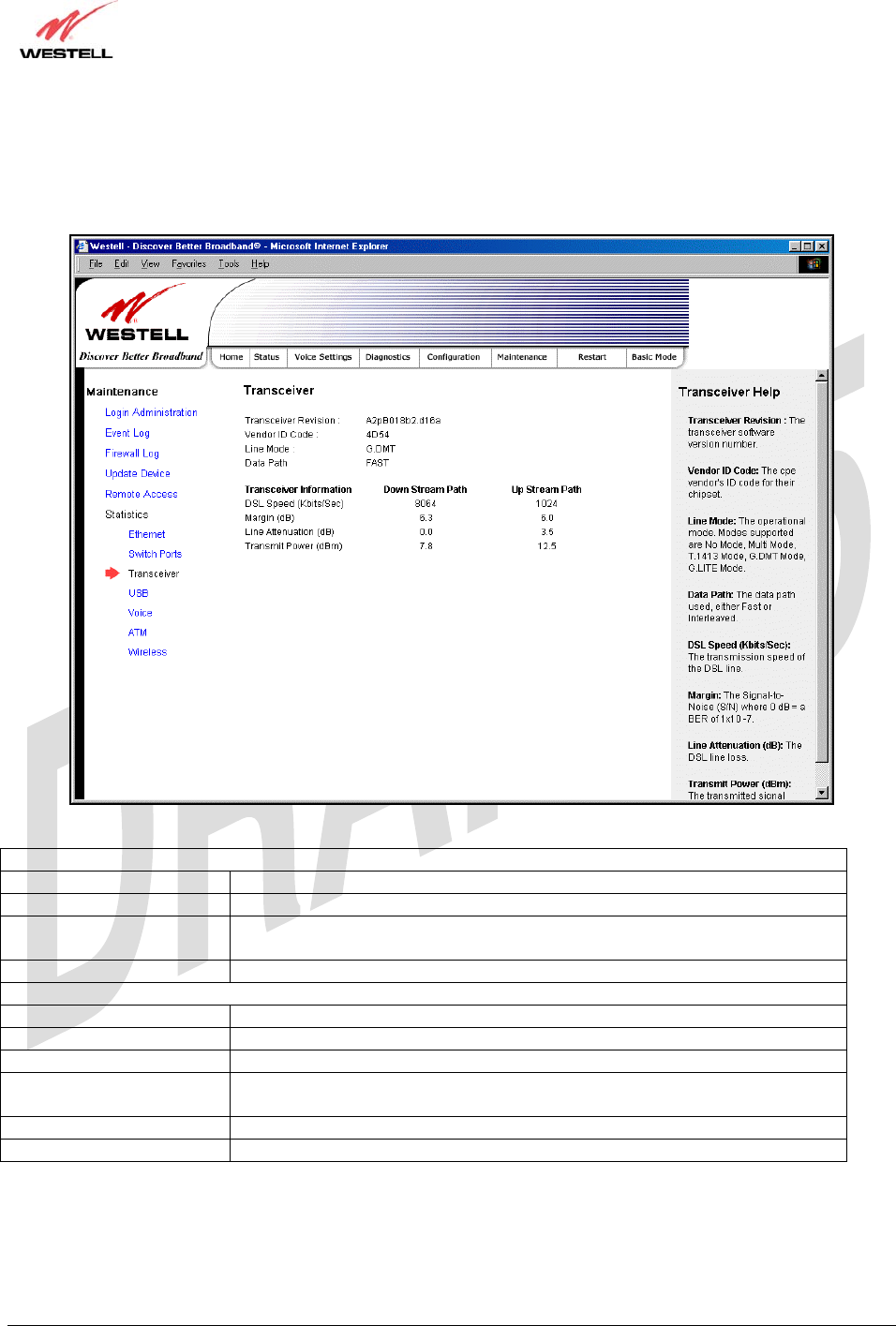
18.6.3 Transceiver Statistics
The following settings will be displayed if you select Transceiver from the Statistics menu.
Transceiver Statistics
Transceiver Revision The transceiver software version number.
Vendor ID Code The CPE Vendor’s ID code for their chipset.
Line Mode The operational mode. Modes supported are No Mode, Multi Mode, T.1413
Mode, G.DMT Mode, and G.LITE Mode.
Data Path The data path used (either Fast or Interleaved).
Transceiver Information-Down Stream/Up Stream Path
Down Stream Path The path from the network to your Router.
Up Stream Path The path from your Router to the network.
DSL Speed (Kbits/Sec) The transmission rate that is provided by your Internet service provider (ISP).
SNR Margin (db) The Signal-to-Noise Ratio (S/N) where 0 db = a BER of 1x10⁻⁷, which inhibits
your DSL speed.
Line Attenuation (dB) The DSL line loss.
Transmit Power (db/Hz) The transmitted signal strength.
TriLink Gateway – Draft 5
030-300445 Rev. A
6/22/05
030-300445 Rev. A 113 June 2005
User Guide TriLink Gateway (Models 427V10, 427V11)
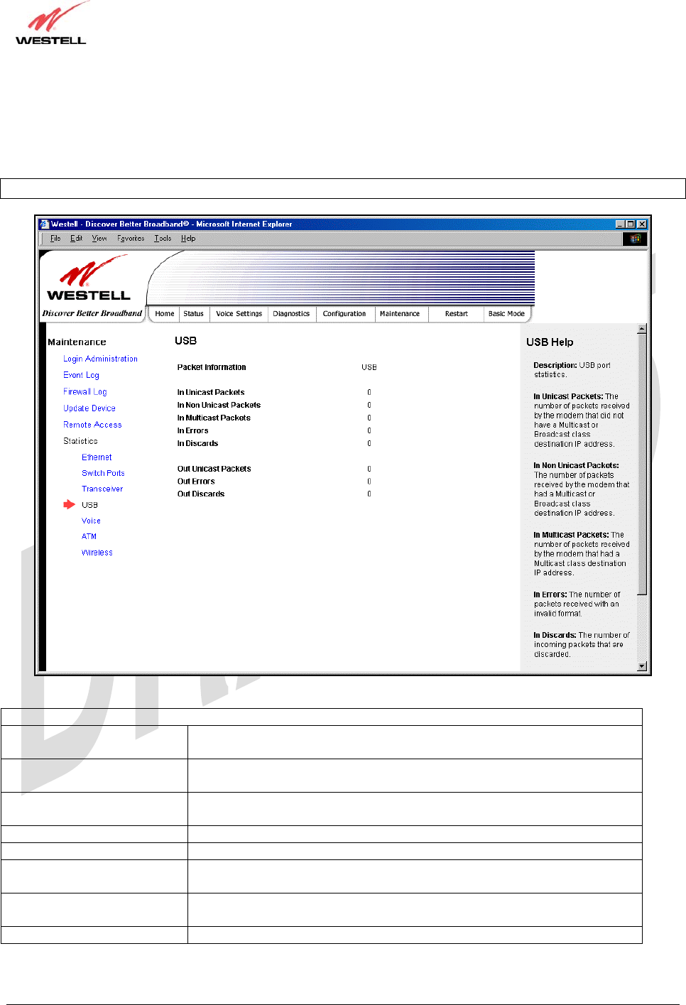
18.6.4 USB Statistics
The following settings will be displayed if you select USB from the Statistics menu.
Note: The values in this screen will be “0” if no USB connection has been established.
USB Statistics
In Unicast Packets The number of packets received by the Router that did not have a Multicast
or Broadcast class destination IP address.
In Non Unicast Packets The number of packets received by the Router that had a Multicast or
Broadcast class destination IP address.
In Multicast Packets The number of packets received by the Router that had a Multicast class
destination IP address.
In Errors The number of packets received with an invalid format.
In Discards The number of incoming packets that were discarded.
Out Unicast Packets The number of packets sent that did not have a Multicast or Broadcast class
destination IP address.
Out Errors The number of packets received by the Router but not sent to PC due to an
error condition.
Out Discards The number of outgoing packets that were discarded.
TriLink Gateway – Draft 5
030-300445 Rev. A
6/22/05
030-300445 Rev. A 114 June 2005
User Guide TriLink Gateway (Models 427V10, 427V11)
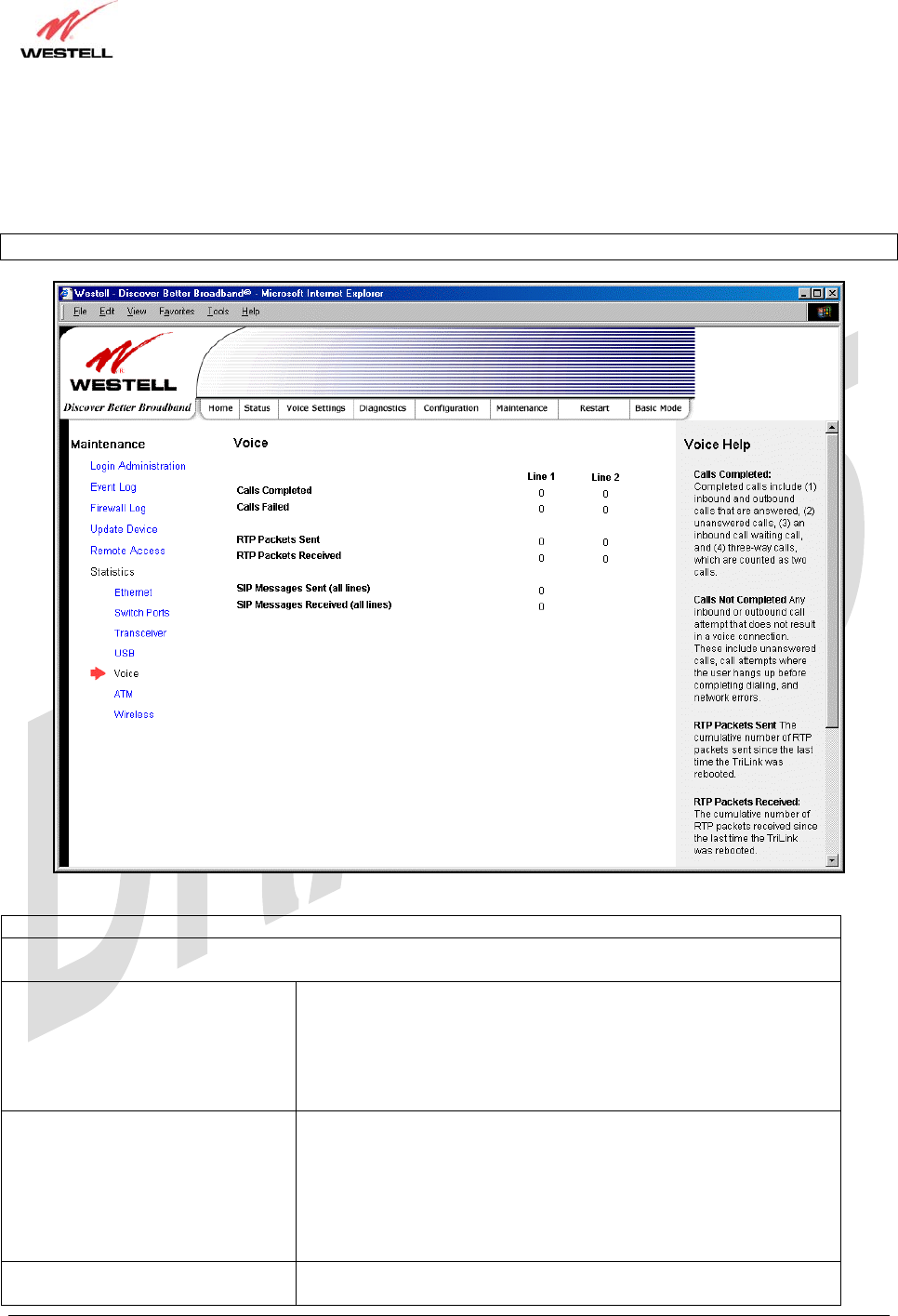
18.6.5 Voice Statistics
The following settings will be displayed if you select Voice from the Statistics menu.
Note: The values in this screen will be “0” if no voice connections have been established.
Voice Statistics
Line 1 = Calls associated with Telephone 1 on the Router.
Line 2 = Calls associated with Telephone 2 on the Router.
Calls Completed The number of completed calls.
Completed calls include:
1) Inbound and Outbound Calls that were answered
2) Unanswered calls
3) An inbound call-waiting call
4) Three-way calls, which are counted as two calls
Called Failed The number of incomplete calls.
Incomplete calls include:
1) Any inbound or outbound call attempt that does not result in a
voice connection.
2) Unanswered calls, call attempts where the user hangs up before
completing dialing.
3) Incomplete calls due to network errors.
RTP Packets Sent The cumulative number of RTP packets sent since the last time the
Router was rebooted.
TriLink Gateway – Draft 5
030-300445 Rev. A
6/22/05
030-300445 Rev. A 115 June 2005
User Guide TriLink Gateway (Models 427V10, 427V11)
RTP Packets Received The cumulative number of RTP packets received since the last time
the Router was rebooted.
SIP Messages Sent (all lines) The cumulative number of SIP messages sent since the last time the
Router was rebooted. This number is the sum for all lines.
SIP Messages Received (all lines) The cumulative number of SIP messages received since the last time
the Router was rebooted. This number is the sum for all lines.
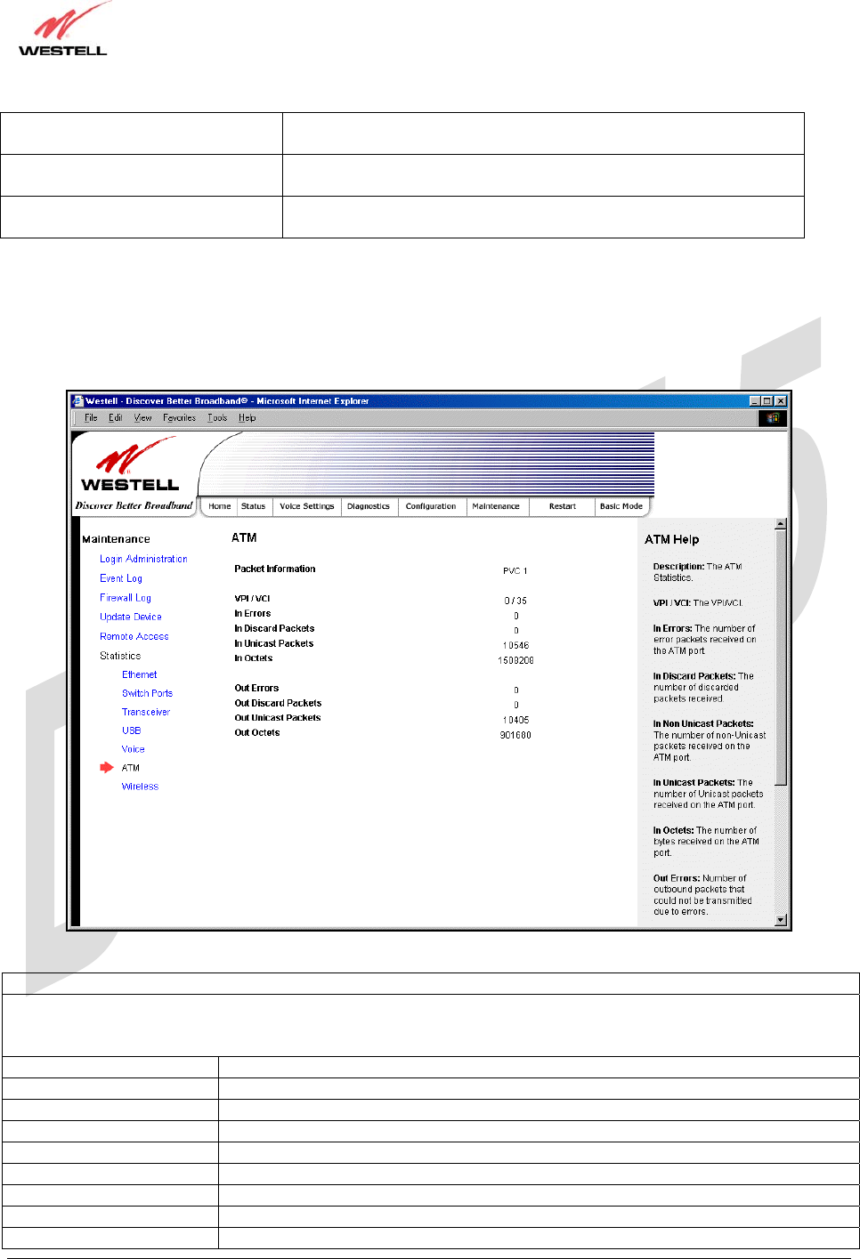
18.6.6 ATM Statistics
The following settings will be displayed if you select ATM from the Statistics menu.
ATM Statistics
NOTE: Data listed in the OUT column pertains to transmissions from the Router’s ATM port to the Internet; the
Router is the source. Data listed in the IN column pertains to data received by the Router’s ATM port from the
Internet; the Router is the destination.
VPI/VCI Displays the VPI/VCI values obtained from your Internet Service Provider.
In Errors The number of error packets received on the ATM port.
In Discard Packets The number of discarded packets received.
In Unicast Packets The number of Unicast packets received on the ATM port.
In Octets The number of bytes received on the ATM port.
Out Errors The number of outbound packets that could not be transmitted due to errors.
Out Discard Packets The number of outbound packets discarded.
Out Unicast Packets The number of Unicast packets transmitted on the ATM port.
Out Octets The number of bytes transmitted on the ATM port.
TriLink Gateway – Draft 5
030-300445 Rev. A
6/22/05
030-300445 Rev. A 116 June 2005
User Guide TriLink Gateway (Models 427V10, 427V11)
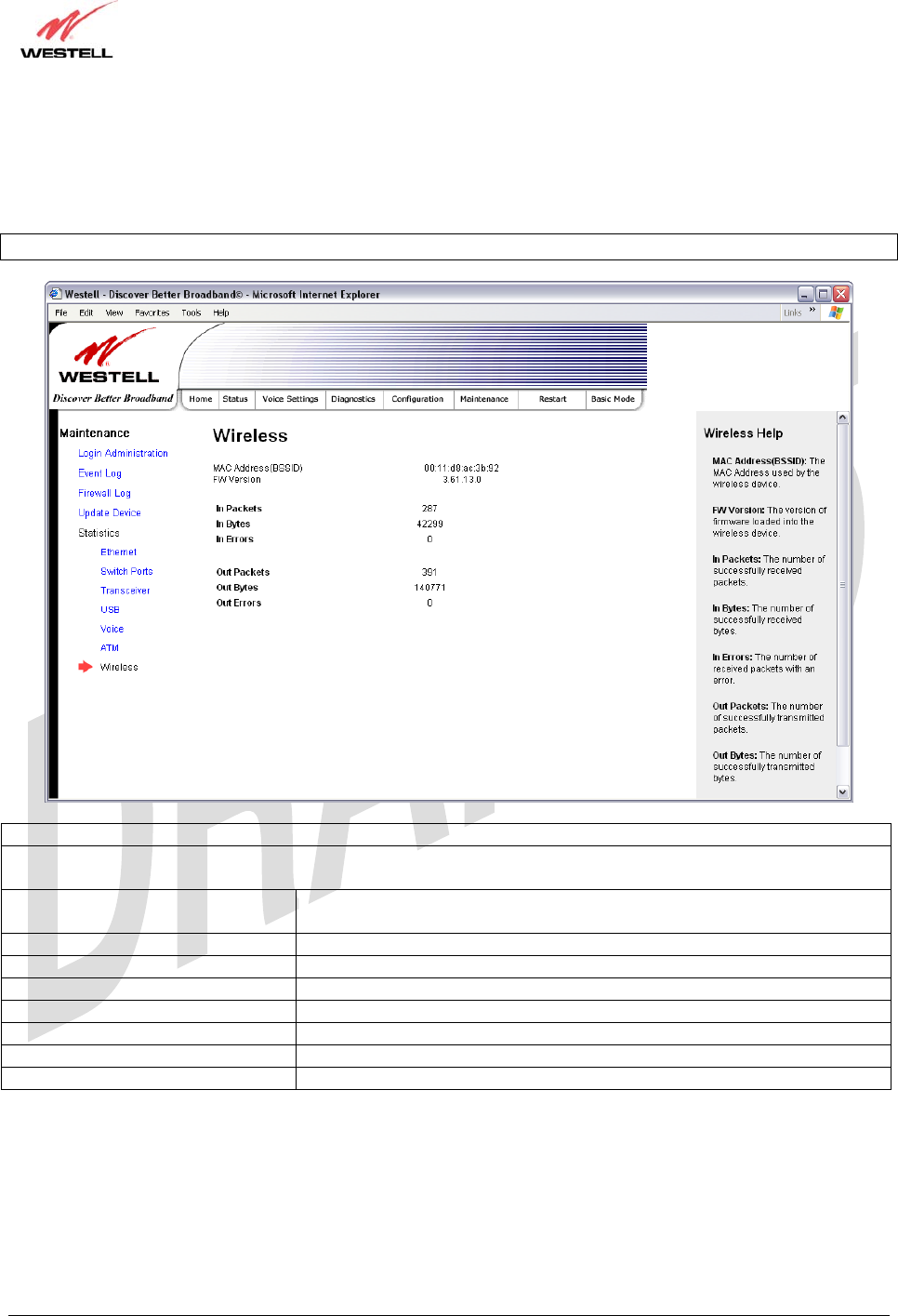
18.6.7 Wireless Statistics
The following settings will be displayed if you select Statistics > Wireless from the Maintenance menu.
Note: The fields in this screen will be blank if no stations are associated with the AP.
Wireless Statistics
NOTE: Data listed in the OUT column pertains to transmissions from the AP to a station; the AP is the source. Data
listed in the IN column pertains to data received by the AP; the AP is the destination.
MAC Address (BSSID) This is the Media Access Controller (the hardware address of the Router). It
is also the Basic Service Set Identifier (BSSID) for your Router.
FW Version The version of application firmware.
In-Packets The number of successfully received packets.
In-Bytes The number of successfully received bytes.
In-Errors The number of received packets with an error.
Out-Packets The number of successfully transmitted packets.
Out-Bytes The number of successfully transmitted bytes.
Out-Errors The number of packets that did not transmit due to an error.

TriLink Gateway – Draft 5
030-300445 Rev. A
6/22/05
030-300445 Rev. A 117 June 2005
User Guide TriLink Gateway (Models 427V10, 427V11)
19. NAT SERVICES
For your convenience, the Router supports protocols for Applications, Games, and VPN-specific programs. The
following chart provides protocol information for the services supported by the Router.
NOTE: To configure the Router for a service or application, follow the steps in section 17.2 (Port Forwarding) of this
User Guide.
Applications/Games/VPN Support
Application/Game Port/Protocol
Aliens vs. Predator 80 UDP, 2300 UDP, 8000-8999 UDP
Age of Empires II: The
Conquerors 6073 UDP, 47624 TCP, 2300-2400 TCP/UDP
This service will open up port’s for both traffic directions
Americas Army TCP - 20045
UDP - 1716 to 1718, 8777, 27900
America Online 5190 TCP/UDP
Anarchy Online TCP/UDP – 7012,7013, 7500 -7505
AOL Instant Messenger 4099 TCP, 5190 TCP
Asheron's Call 9000-9013 UDP, 28800-29000 TCP
Battlecom 2300-2400 TCP/UDP, 47624 TCP/UDP
Battlefield 1942 UDP - 14567, 22000, 23000 to 23009, 27900, 28900
Black and White 2611-2612 TCP, 6667 TCP, 6500 UDP, 27900 UDP
Blizzard Battle.net (Diablo II) 4000 TCP, 6112 TCP/UDP
Buddy Phone 700, 701 UDP
Bungie.net, Myth, Myth II
Server 3453 TCP
Calista IP Phone 3000 UDP, 5190 TCP
Citrix Metaframe 1494 TCP
Client POP/IMAP 110 TCP
Client SMTP 25 TCP
Counter Strike 27015 TCP/UDP, 27016 TCP/UDP
Dark Reign 2 26214 TCP/UDP
Delta Force ( Client and
Server ) 3568 UDP, 3100-3999 TCP/UDP
Delta Force 2 3568-3569 UDP
DeltaForce: Land Warrior UDP 53
TCP 21
TCP 7430
TCP 80
UDP 1029
UDP 1144
UDP 65436
UDP 17478
DNS 53 UDP
Elite Force 2600 UDP, 27500 UDP, 27910 UDP, 27960 UDP
Everquest 1024-7000 TCP/UDP
F-16, Mig 29 3863 UDP
F-22 Lightning 3 4660-4670 TCP/UDP, 3875 UDP, 4533-4534 UDP, 4660-4670 UDP
F-22 Raptor 3874-3875 UDP
Fighter Ace II 50000-50100 TCP/UDP
Fighter Ace II for DX play 50000-50100 TCP/UDP, 47624 TCP, 2300-2400 TCP/UDP

TriLink Gateway – Draft 5
030-300445 Rev. A
6/22/05
030-300445 Rev. A 118 June 2005
User Guide TriLink Gateway (Models 427V10, 427V11)
Application/Game Port/Protocol
FTP 20 TCP, 21 TCP
GameSpy Online UDP 3783
UDP 6515
TCP 6667
UDP 12203
TCP/UDP 13139UDP 27900
UDP 28900
UDP 29900
UDP 29901
Ghost Recon TCP 80
UDP 1038
UDP 1032
UDP 53
UDP 2347
UDP 2346
GNUtella 6346 TCP/UDP, 1214 TCP
Half Life Server 27005 UDP(client only)
27015 UDP
Heretic II Server 28910 TCP
Hexen II 26900 (+1) each player needs their own port. Increment by one for
each person
Hotline Server 5500, 5503 TCP 5499 UDP
HTTPS 443 TCP/UDP
ICMP Echo 4 ICMP
ICQ OLD 4000 UDP, 20000-20019 TCP
ICQ 2001b 4099 TCP, 5190 TCP
ICUII Client 2000-2038 TCP, 2050-2051 TCP, 2069 TCP, 2085 TCP, 3010-3030
TCP
ICUII Client Version 4.xx 1024-5000 TCP, 2050-2051 TCP, 2069 TCP, 2085 TCP, 3010-3030
TCP, 2000-2038 TCP6700-6702 TCP, 6880 TCP, 1200-16090 TCP
IMAP 119 TCP/UDP
IMAP v.3 220 TCP/UDP
Internet Phone 22555 UDP
IPSEC ALG ENABLES ALG
IPSEC ESP PROTOCOL 50
IPSEC IKE 500 UDP
Ivisit 9943 UDP, 56768 UDP
JKII:JO (Jedi Knight II: Jedi
Outcast) UDP - 28070 (default)
UDP- 27000 to 29000
KALI, Doom & Doom II 2213 UDP, 6666 UDP (EACH PC USING KALI MUST USE A
DIFFERENT PORT NUMBER STARTING WITH 2213 + 1
KaZaA 1214 TCP/UDP
Limewire 6346 TCP/UDP, 1214 TCP
Medal Of Honor: Allied
Assault TCP 80
UDP 53
UDP 2093
UDP 12201
TCP 12300
UDP 2135
UDP 2139
TCP/UDP 28900
mIRC Chat 6660-6669 TCP
Motorhead Server 16000 TCP/UDP, 16010-16030 TCP/UDP

TriLink Gateway – Draft 5
030-300445 Rev. A
6/22/05
030-300445 Rev. A 119 June 2005
User Guide TriLink Gateway (Models 427V10, 427V11)
Application/Game Port/Protocol
MSN Game Zone 6667 TCP, 28800-29000 TCP
MSN Game Zone (DX 7 & 8
play) 6667 TCP, 6073 TCP, 28800-29000 TCP, 47624 TCP, 2300-2400
TCP/UDP
This service will open up port’s for both traffic directions.
MSN Messenger 6891-6900 TCP, 1863 TCP/UDP, 5190 UDP, 6901 TCP/UDP
Napster 6699 TCP
Need for Speed 3, Hot Pursuit 1030 TCP
Need for Speed, Porsche 9442 UDP
Net2Phone 6801 UDP
NNTP 119 TCP/UDP
Operation FlashPoint 47624 UDP, 6073 UDP, 2300-2400 TCP/UDP, 2234 TCP
Outlaws 5310 TCP/UDP
Pal Talk 2090-2091 TCP/UDP, 2095 TCP, 5001 TCP, 8200-8700 TCP/UDP,
1025-2500 UDP
pcAnywhere host 5631 TCP, 5632 UDP, 22 UDP
Phone Free 1034-1035 TCP/UDP, 9900-9901 UDP, 2644 TCP, 8000 TCP
Quake 2 27910 UDP
Quake 3 27660 UDP
Each computer playing QuakeIII must use a different port number,
starting at 27660 and incrementing by 1. You'll also need to do the
following:
1. Right click on the QIII icon
2. Choose "Properties"
3. In the Target field you'll see a line like "C:\Program Files\Quake III
Arena\quake3.exe"
4. Add the Quake III net_port command to specify a unique
communication port for each system. The complete field should look
like this: "C:\Program Files\Quake III Arena\quake3.exe" +set
net_port 27660
5. Click OK.
6. Repeat for each system behind the NAT, adding one to the net_port
selected (27660,27661,27662)
Quicktime 4/Real Audio 6970-32000 UDP, 554 TCP/UDP
Rainbow Six & Rogue Spear 2346 TCP
RealOne Player TCP - 554, 7070 to 7071
UDP - 6970 to 7170
Real Audio 6970-7170 UDP
Return To Castle Wolfenstein Default -27960 TCP/UDP
UDP - 27950 to 27980
Roger Wilco TCP/UDP 3782
UDP 3783 (BaseStation)
ShoutCast Server 8000-8005 TCP
Spinner Radio/Netscape
Music TCP - 554
SSH Secure Shell 22 TCP/UDP
Starcraft 2346 TCP
Starfleet Command 2300-2400 TCP/UDP, 47624 TCP/UDP
SOF/SOFII (Soldier of
Fortune / Soldier of Fortune
II)
UDP - 28910 to 28915
Telnet 23 TCP
Tiberian Sun & Dune 2000 1140-1234, 4000 TCP/UDP
Tribes2 TCP - 15104, 15204, 15206, 6660 to 6699

TriLink Gateway – Draft 5
030-300445 Rev. A
6/22/05
030-300445 Rev. A 120 June 2005
User Guide TriLink Gateway (Models 427V10, 427V11)
Application/Game Port/Protocol
UDP - 27999 to 28002
Ultima Online 5001-5010 TCP, 7775-7777 TCP, 8800-8900 TCP, 9999 UDP, 7875
UDP
Unreal Tournament server 7777 (default gameplay port)
7778 (server query port
7779,7779+ are allocated dynamically for each helper UdpLink
objects, including UdpServerUplin objects. Try starting with 7779-
7781 and add
ports if needed
27900 server query, if master server uplink is enabled. Home master
servers use other ports like 27500
Port 8080 is for UT Server Admin. In the [UWeb.WebServer] section
of the server.ini file, set the ListenPort to 8080 and ServerName to the
IP assigned to the router from your ISP.
USENET News Service 143 TCP
VNC, Virtual Network
Computing 5500 TCP, 5800 TCP, 5900 TCP
Westwood Online, C&C 4000 TCP/UDP, 1140-1234 TCP/UDP
World Wide Web (HTTP) 80 TCP
443 TCP (SSL)
8008 OR 8080 TCP (PROXY)
Yahoo Messenger Chat 5000-5001 TCP
Yahoo Messenger Phone 5055 UDP
IPSec Encryption IPSec using AH can not be supported through NAT. IPSec using ESP
and L2TP can be supported via an ALG
L2TP IPSec using ESP and L2TP can be supported via an ALG.
PPTP Works through NAT.

TriLink Gateway – Draft 5
030-300445 Rev. A
6/22/05
030-300445 Rev. A 121 June 2005
User Guide TriLink Gateway (Models 427V10, 427V11)
20. PRODUCT SPECIFICATIONS
Voice Over IP Features
Signaling Protocol
• SIP version 2 (RFC 3261)
Voice Codecs
• G.711 µ-law
• G.711 A-law
• G.729A
• G.723.1
Voice Processing Features
• G.168 Echo Cancellation
• Silence Suppression and Voice Activity
Detection functions
• Comfort Noise Generation
• DTMF detection and generation
• DTMF Relay per RFC 2833
• Caller ID generation
• Adaptive Jitter Butter
• Packet loss recovery/concealment
• G.711 clear channel support for FAX, modem
and alarm operation.
Data Features
• Network Address Port Translation
• DHCP client/server
• DNS server/relay
• Static Routes
• Dynamic Routing with RIP v1 and v2
• PPTP/L2TP/IPSEC VPN NAPT passthrough
• NAT ALG support for common applications
• Stateful Inspection Firewall with logging
• Diffserv IP QOS
ADSL WAN
DSL Standards
• ANSI T1.413 issue 2
• ITU G.992.1 (G.DMT) and S=1/2
• ITU G.992.2 (G.lite)
• ITU G.992.3 (ADSL2 DMT)
• ITU G.992.3 Annex L READSL
• ITU G.992.4 (ADSL2 G.lite)
• ITU G.992.5 (ADSL2+)
WAN Protocol Features
• Bridge Encapsulation per RFC 1483
• Routed IP over ATM per RFC 2684
• PPP over Ethernet per RFC 2516
• PPP over ATM per RFC 2364
• Auto Protocol Detect
ATM Features
• Multi PVC support
• Auto PVC detect
• CBR, VBR-rt, VBR-nrt and UBR traffic
shaping
• OAM F4/F5 Loop-back
VersaPort™2 WAN/LAN
• Single 10/100 Base-T Ethernet
• Auto MDI/MDI-X detection
• Operates as an uplink, public LAN (DMZ) or
as a fifth LAN port
Uplink Features
• PPP over Ethernet per RFC 2516
• DHCP client
• Static IP address
Public LAN Features
• Dedicated DMZ port
• DHCP server
• Bridge mode mapped to a separate PVC
Ethernet LAN
• Four port 10/100 Base-T Ethernet switch
• Auto MDI/MDI-X detection
• VLAN tagging
Wireless LAN
• IEEE 802.11b/g with frame bursting
• WEP and WPA-PSK security
• MAC address filtering
• Upgradable to 802.11i, 802.11e, WME
• High gain removable external antenna
Management
• Web-based GUI
• Remote management via TR-069 or WT-087

TriLink Gateway – Draft 5
030-300445 Rev. A
6/22/05
030-300445 Rev. A 122 June 2005
User Guide TriLink Gateway (Models 427V10, 427V11)
System Requirements
Ethernet
• Pentium® or equivalent and above machines
• Microsoft Windows (98 SE, 2000, ME, NT
4.0, or XP), Macintosh OS X, or Linux
installed
• Internet Explorer 4.x or Netscape Navigator
4.x or higher
• Ethernet 10/100 Base-T interface
• TCP/IP Protocol stack installed
USB
• Pentium or equivalent and above class
machines
• Microsoft Windows (98 SE, ME, 2000
or XP) installed
• Operating system CD on hand
• Internet Explorer 4.x or Netscape
Navigator 4.x or higher
• 64 MB RAM (128 MB recommended)
• 10 MB of free hard drive space
• USB Version 1.0 or higher compliant bus
Wireless
• Pentium® or equivalent and above class
machines
• Microsoft® Windows® (98 ME, 2000, or XP)
or Macintosh® OS X installed
• Operating System CD on hand
• Internet Explorer 4.x or Netscape Navigator
4.x or higher
• 64 MB RAM (128 MB recommended)
• 10 MB of free hard drive space
• IEEE 802.11b/g/g+ PC adapter
Physical Specifications
Dimensions/Weight
• Height: 1.5 in (3.81 cm)
• Width: 10.0 in (25.4 cm)
• Depth: 6.50 in (16.5 cm)
• Weight: Approx. 1.26 lbs. (0.57 kg)
Environmental
• Ambient Operating Temperature: +32° to
+104° F (0° to +40° C)
• Relative Humidity: 5 to 95%, non-condensing
Network Interface
• WAN: 10/100 Base-T RJ-45 port
• LAN: 10/100 Base-T RJ-45 port (to PC or Hub)
Power
• Power Adapter:
Input: AC 120V/
Output: DC +12V
• Power Consumption: Less than 14W typical
from 120 VAC
LED Indicators
• Power
• VersaPort™2
• Ethernet
• Wireless
• Telephone 1, Telephone 2
• Message waiting 1, Message waiting 2
• USB
• DSL
• Internet
Connectors
• DSL: 6-pin (RJ-11)
• USB: 4-pin Type B connector (Model 42710 only)
• VersaPort™2: Ethernet 8-pin RJ-45
• Four Ethernet: 8-pin RJ-45
• Two VoIP Jacks: Telephone 1, Telephone 2
6-pin (RJ-11)
• Power: Barrel connector
• Wireless IEEE 802.11b/g SMA connector and
antenna
Compliance
EMC
• FCC Part 15 Class B
Safety
• UL 1950, 3rd Edition
• cUL, CAN/CSA-22.2 950-93
Regulatory Approval
• UL, CSA, FCC Part 68, Industry Canada
CS03, LE

TriLink Gateway – Draft 5
030-300445 Rev. A
6/22/05
030-300445 Rev. A 123 June 2005
User Guide TriLink Gateway (Models 427V10, 427V11)
21. TECHNICAL SUPPORT INFORMATION
Westell Technical Support
If technical assistance is required, contact your Internet service provider for support. By using one of the following
options:
North America U.K./Europe
Phone: 1-630-375-4900 Phone: (44) 01256 843311
Visit Westell at www.Westell.com to view frequently asked questions and enter on-line service requests, or send
email to global_support@westell.com to obtain additional information.
22. WARRANTY AND REPAIRS
Warranty
Westell warrants this product free from defects at the time of shipment. Westell also warrants this product fully
functional for the period specified by the terms of the warranty. Any attempt to repair or modify the equipment by
anyone other than an authorized representative will void the warranty.
Repairs
Westell will repair any defective Westell equipment without cost during the warranty period if the unit is defective
for any reason other than abuse, improper use, or improper installation, or acts of nature. Before returning the
defective equipment, request a Return Material Authorization (RMA) number from Westell. An RMA number
must be quoted on all returns. When requesting an RMA, please provide the following information:
• Product model number (on product base)
• Product serial number (on product base)
• Customer ship-to address
• Contact name
• Problem description
• Purchase date
After an RMA number is obtained, return the defective unit, freight prepaid, along with a brief description of the
problem to one of the following options:
North America U.K./Europe
Westell, Inc. Westell, Ltd.
ATTN: R.G.M Department Ringway House
750 N. Commons Drive Bell Road
Aurora, IL 60504-7940 USA Daneshill
Basingstoke
RG24 8FB
United Kingdom
Westell will continue to repair faulty equipment beyond the warranty period for a nominal charge. Contact a Westell
Technical Support Representative for details.

TriLink Gateway – Draft 5
030-300445 Rev. A
6/22/05
030-300445 Rev. A 124 June 2005
User Guide TriLink Gateway (Models 427V10, 427V11)
23. PUBLICATION INFORMATION
Westell® TriLink™ (Models 427V10, 427V11)
User Guide Part Number 030-300445 Rev. A
Copyright © 2005 Westell, Inc.
All rights reserved.
Westell, Inc.
750 North Commons Drive
Aurora, Illinois 60504 USA
www.westell.com
All trademarks and registered trademarks are the property of their respective owners.