Westell A9081XXYY-07 Spread Spectrum Transmitter User Manual 5645 rev 1
Westell Inc Spread Spectrum Transmitter 5645 rev 1
UserManual.wiki
>
Westell
>
A9081XXYY 07 User Manual
Users Manual
Navigation menu
Upload a User Manual
Namespaces
Wiki Guide
HTML
PDF
Info
Views
User Manual
Discussion / Help
Navigation

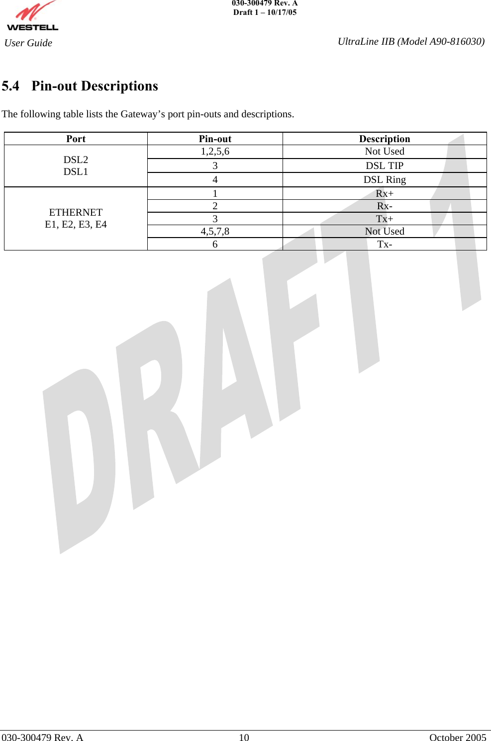
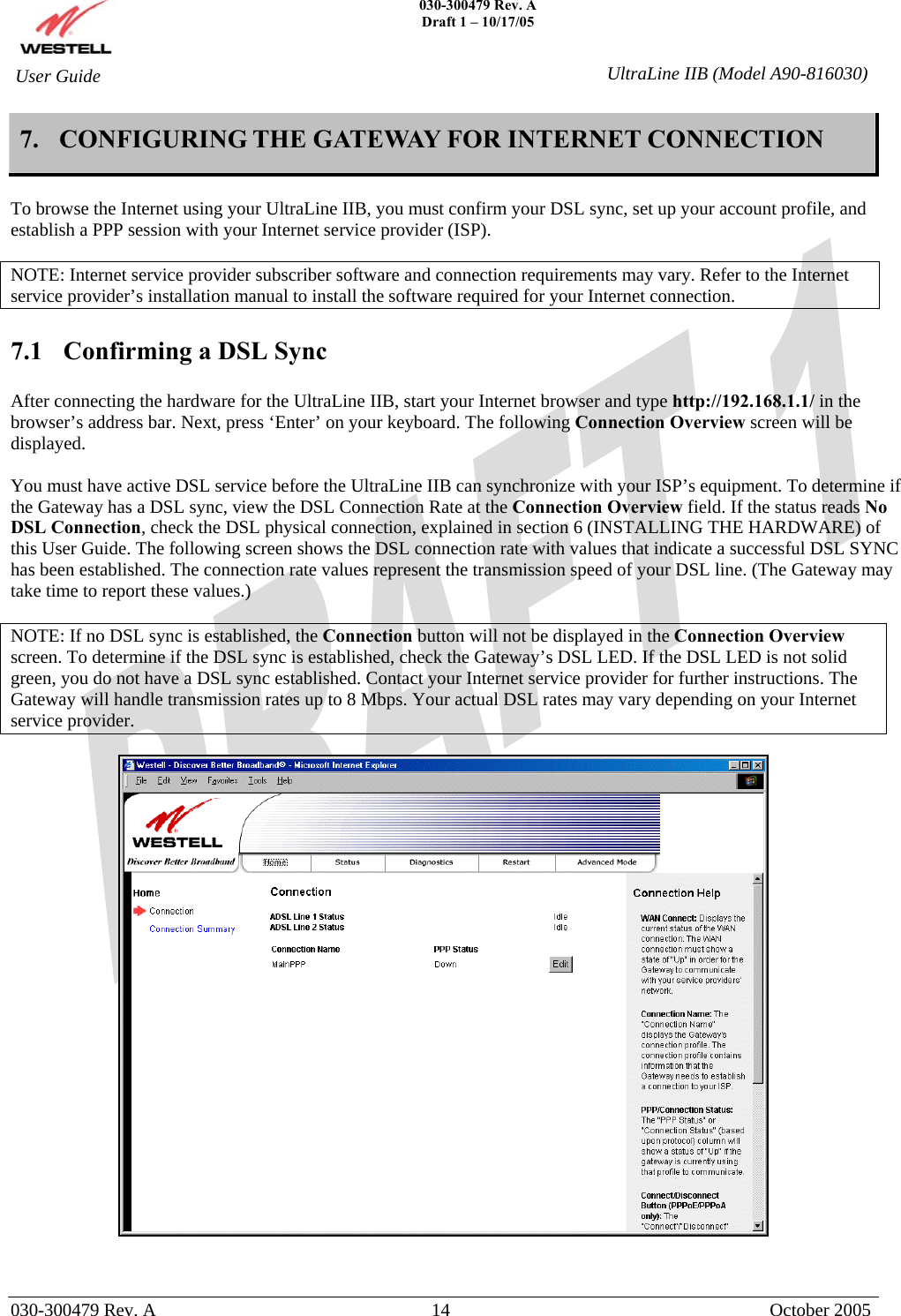
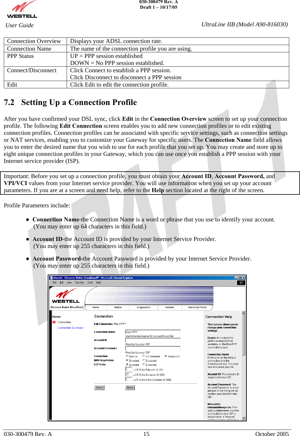
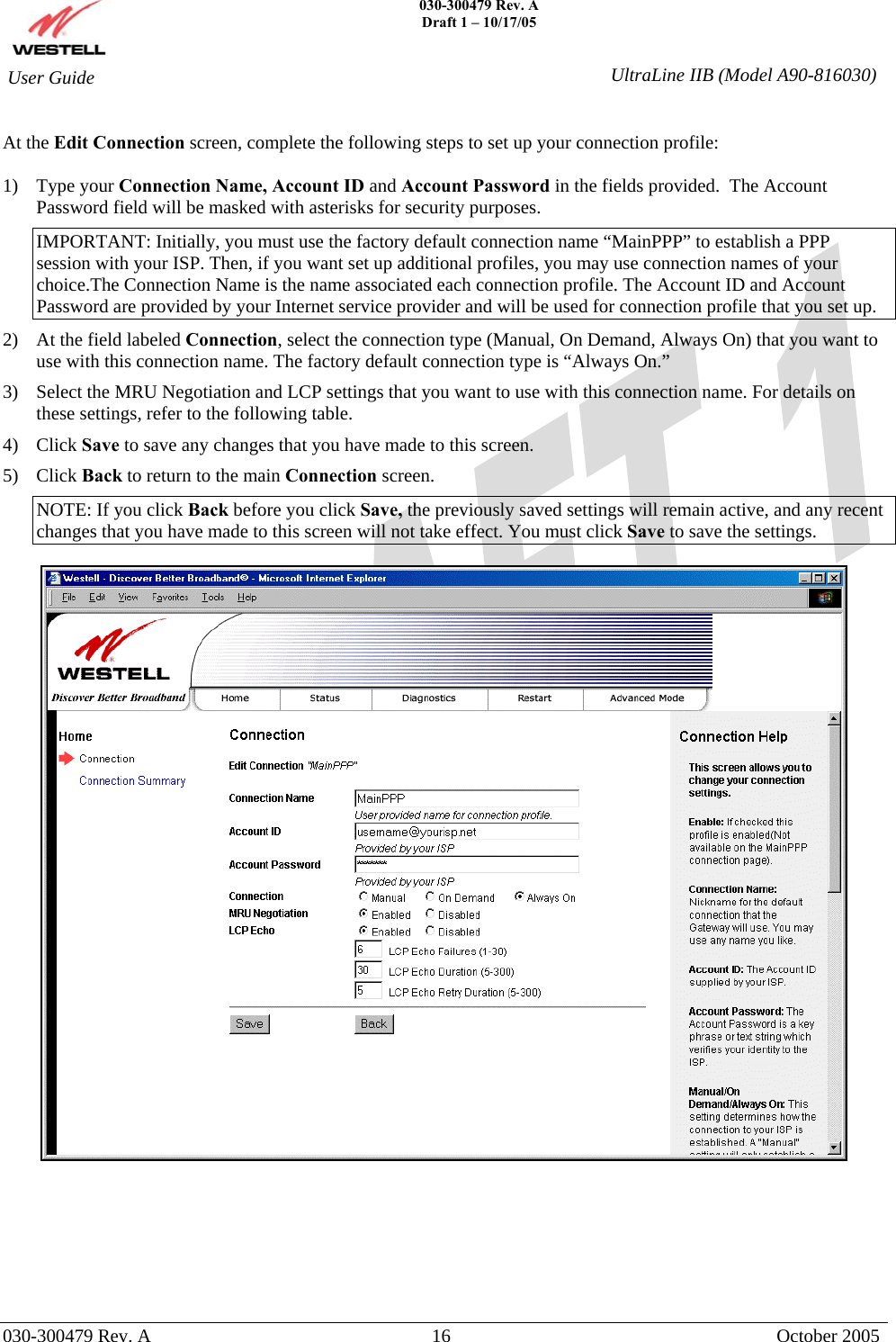
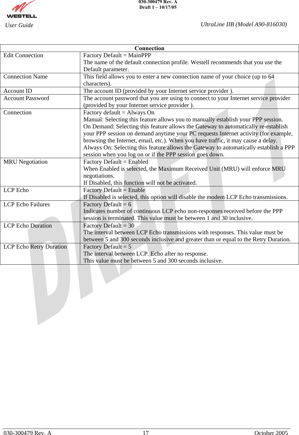
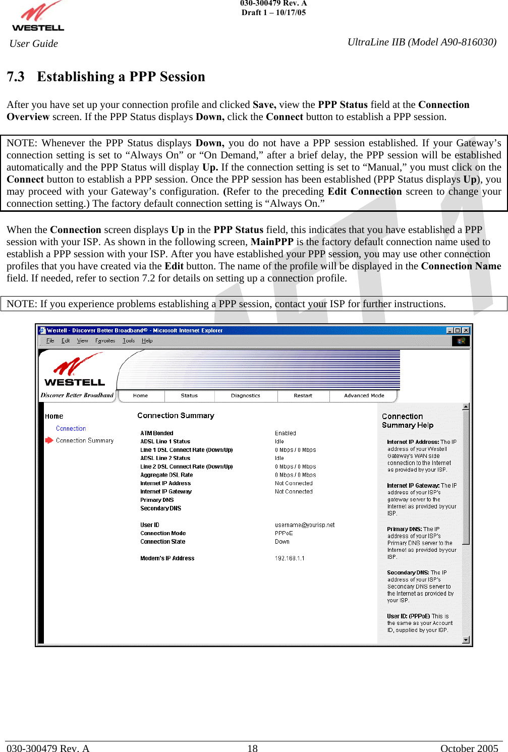
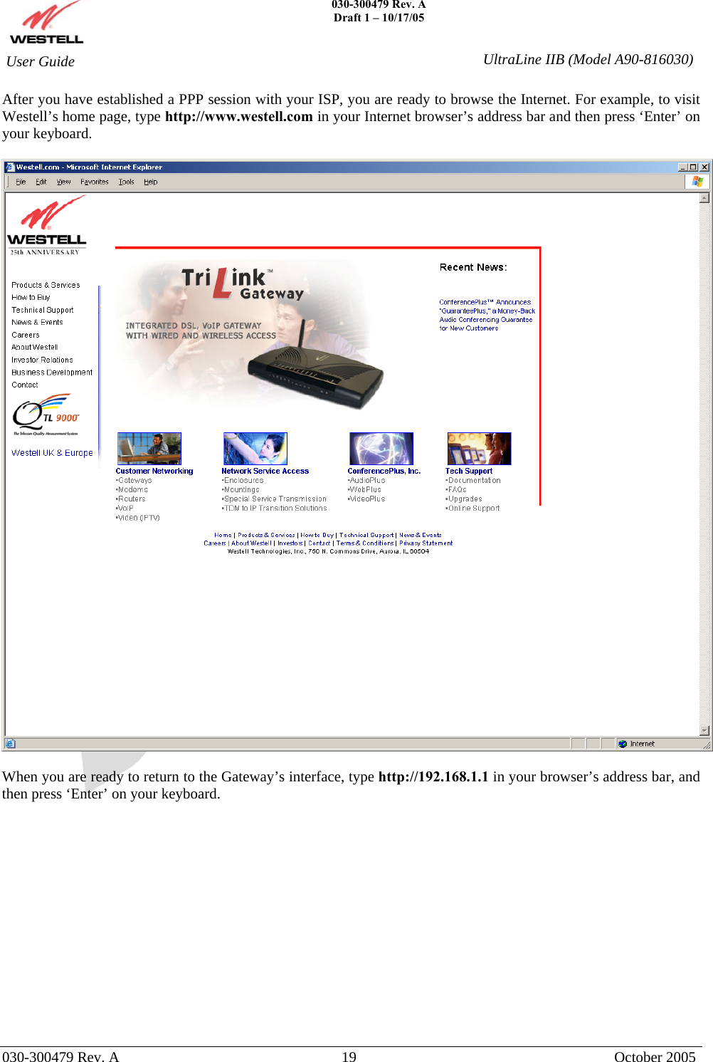
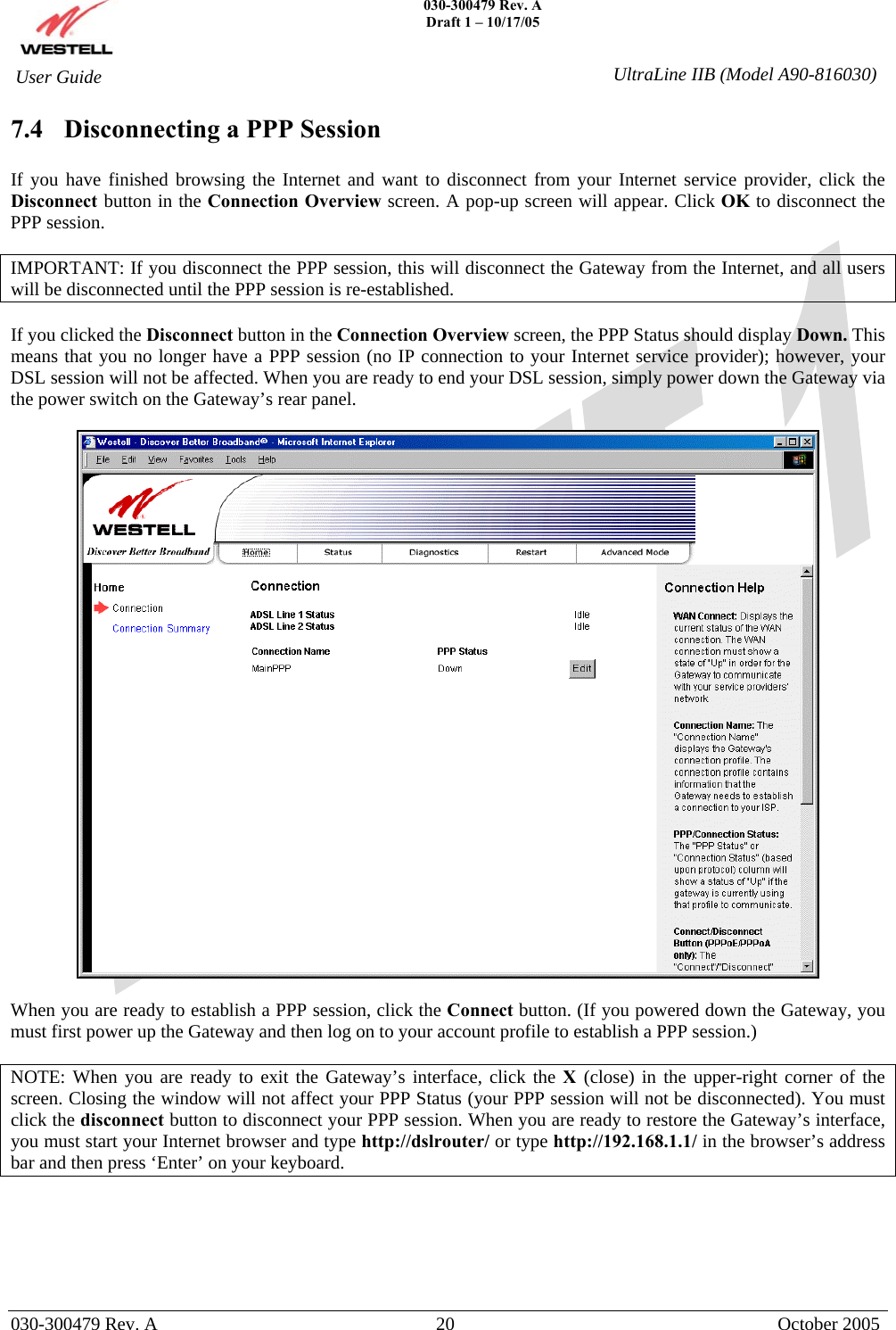
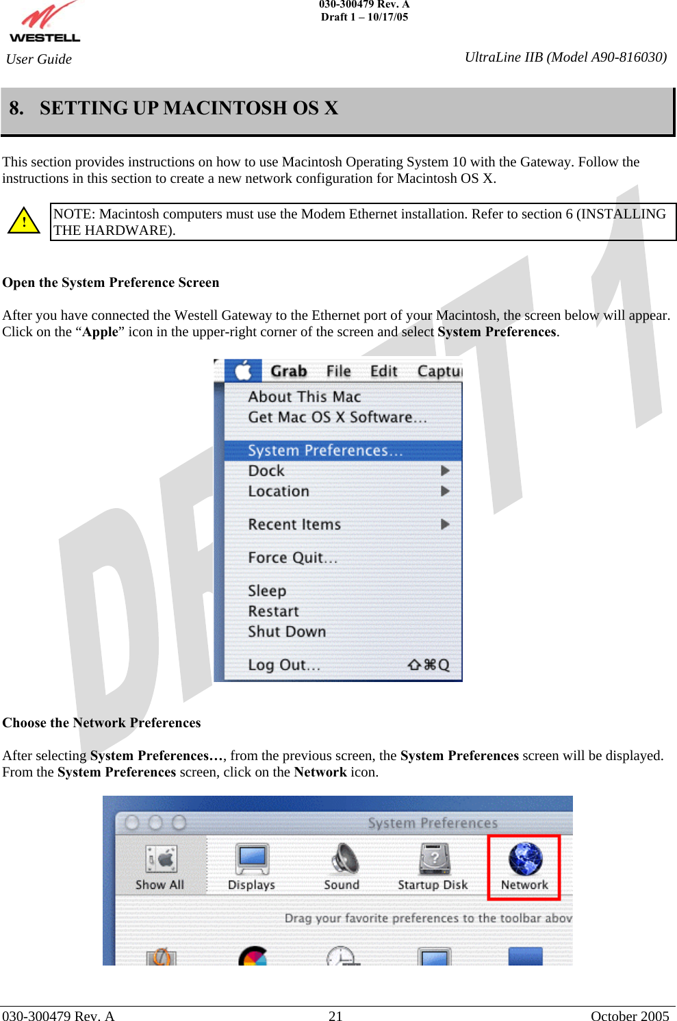
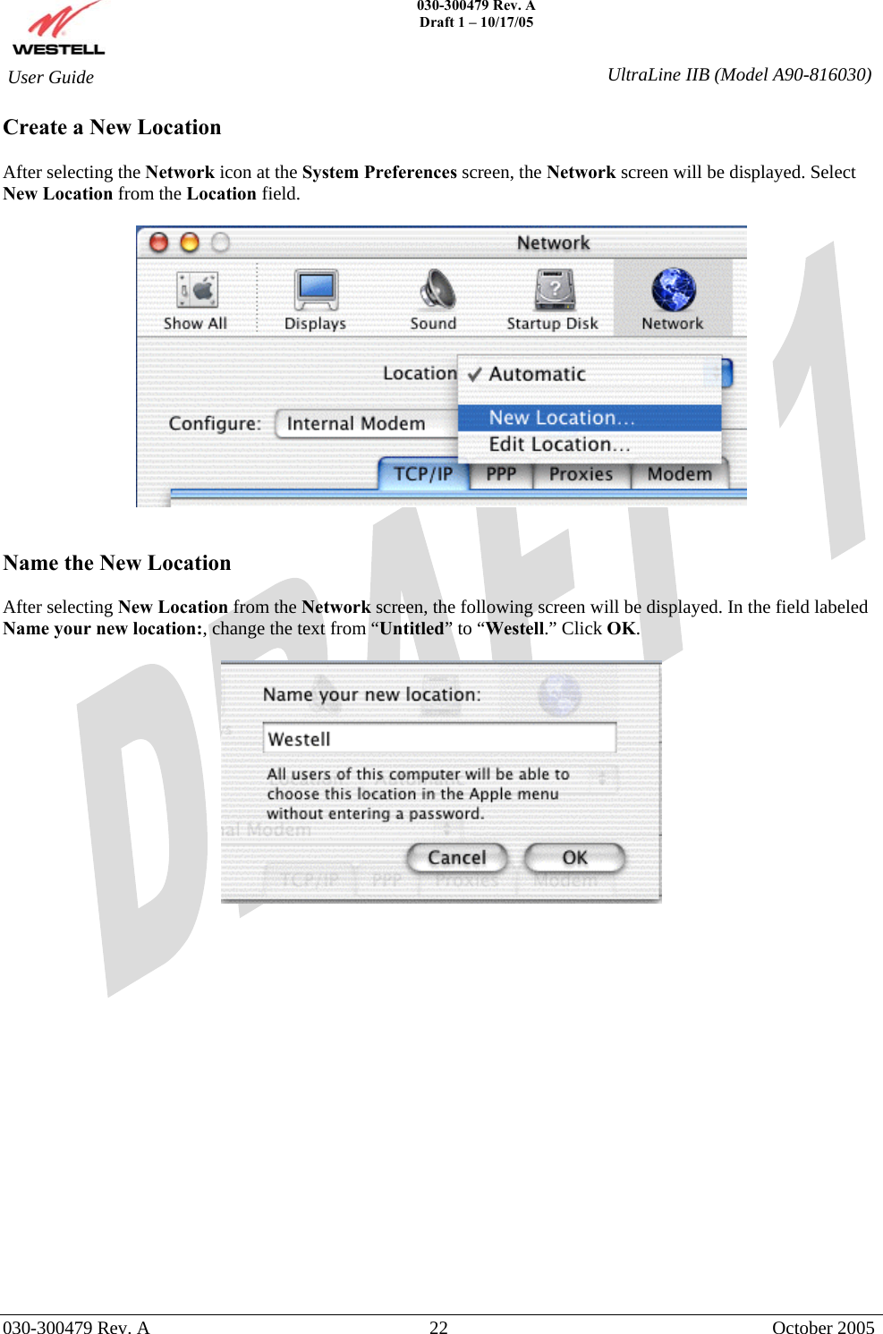
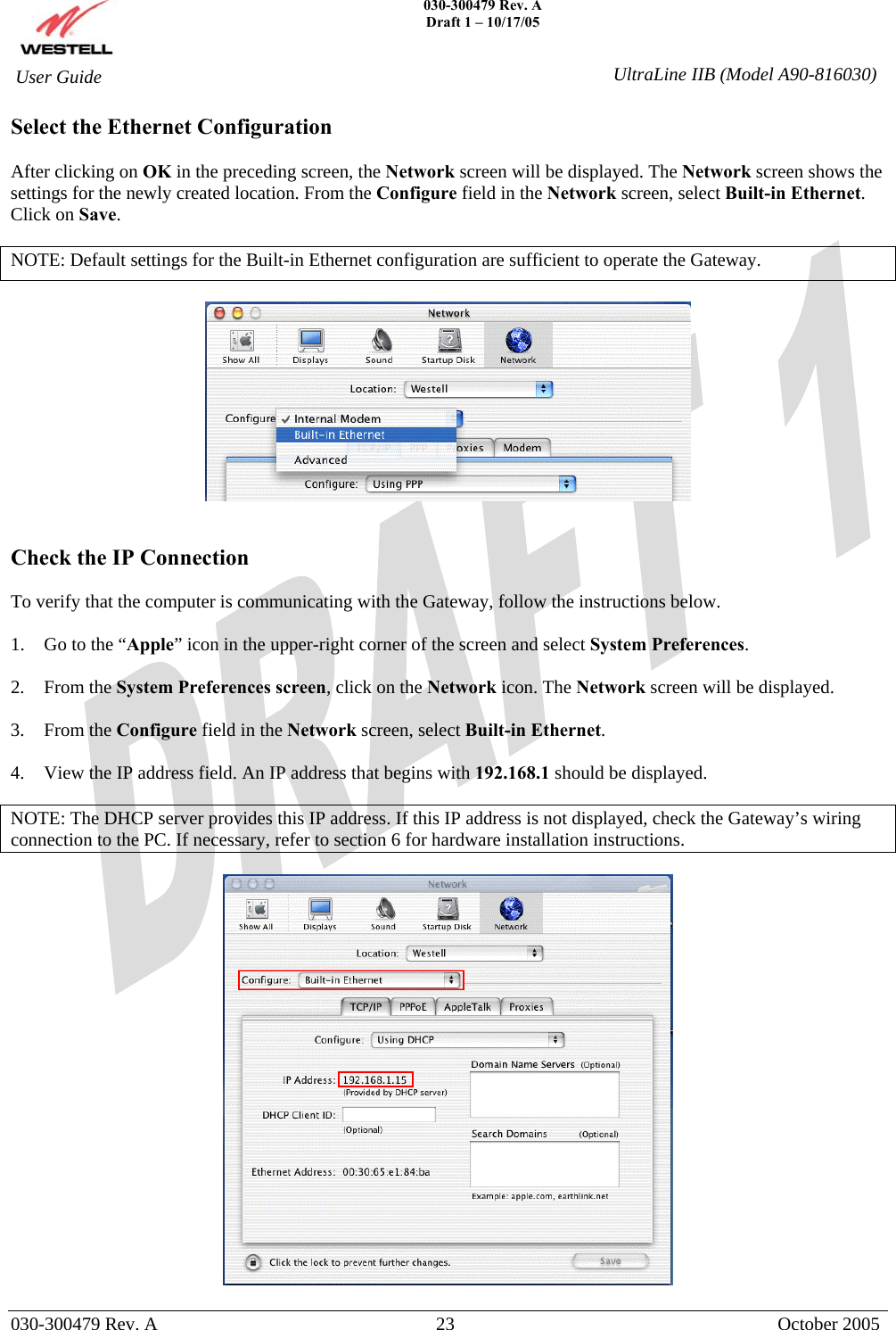
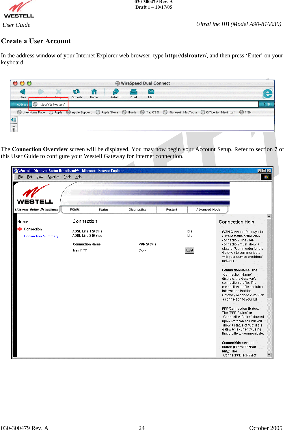
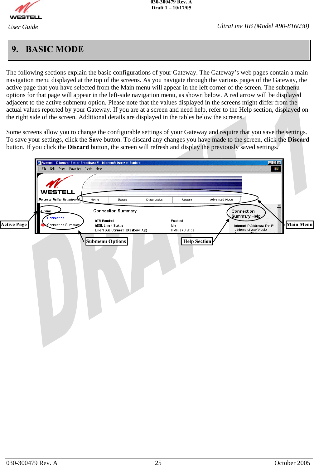
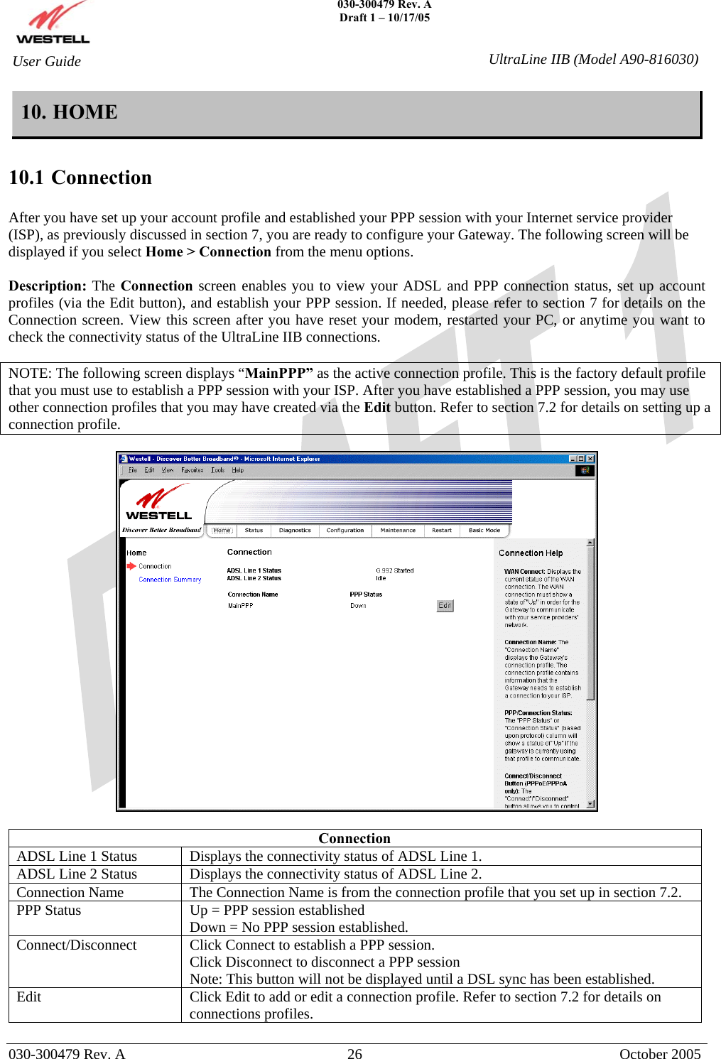
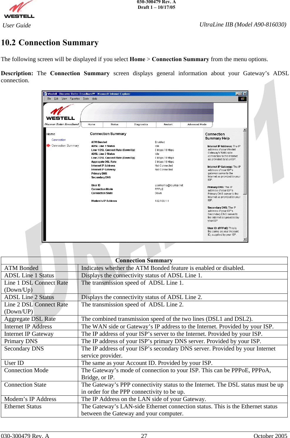
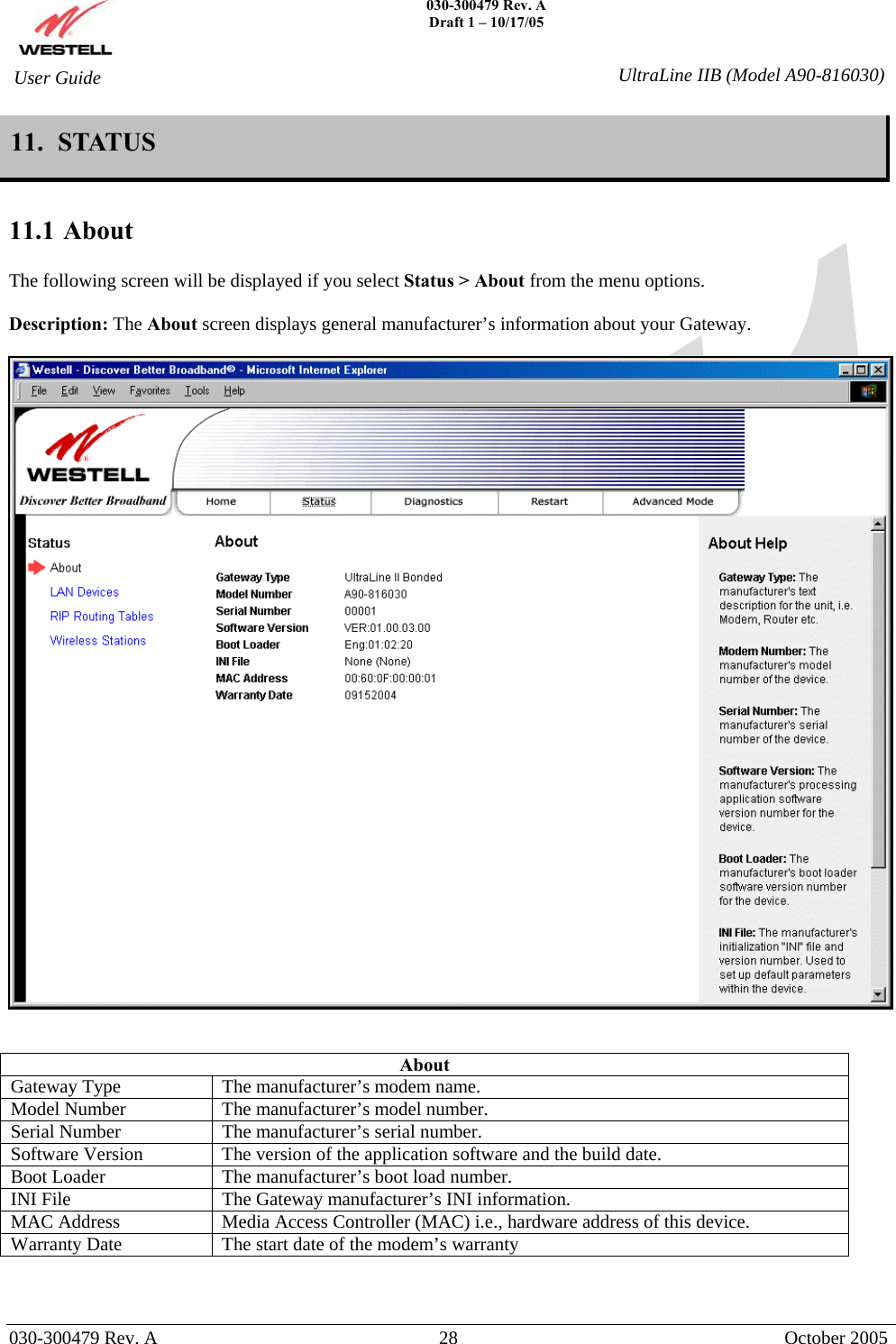
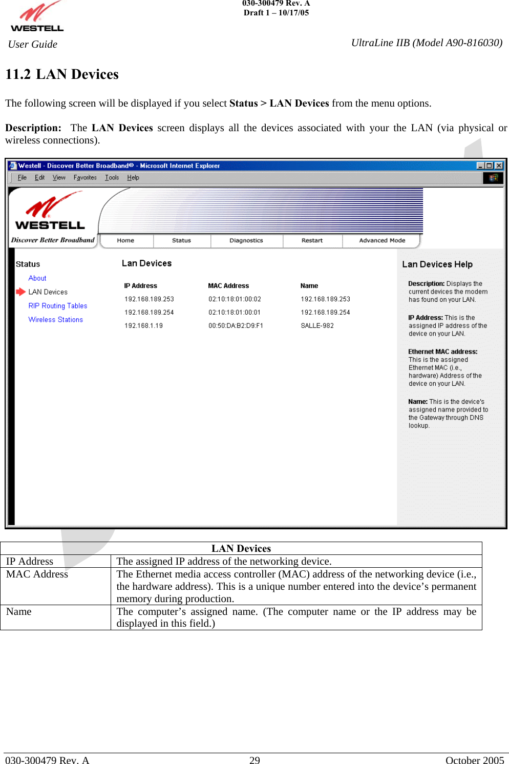
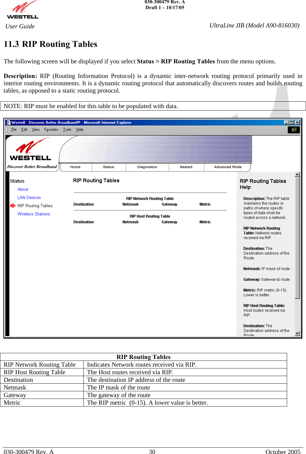
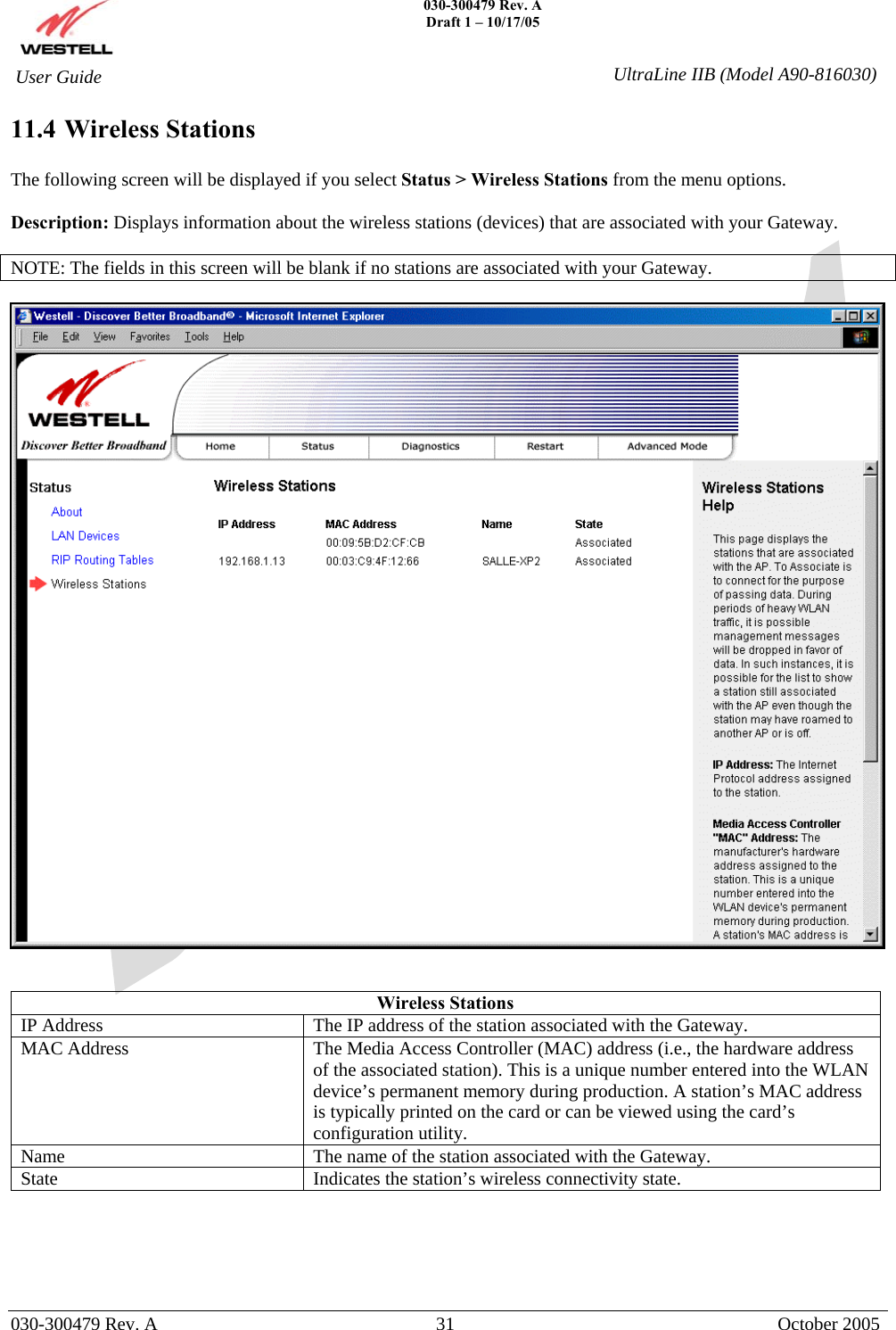
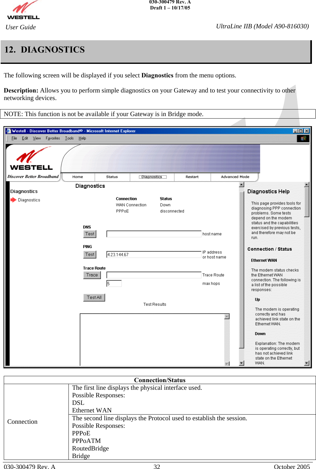
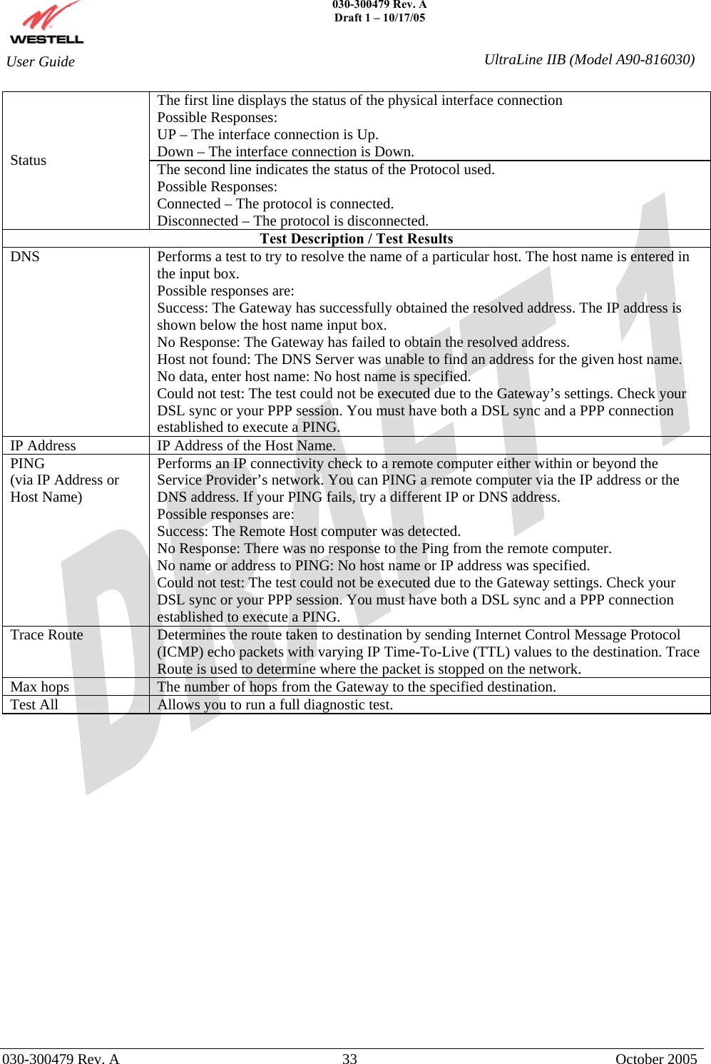
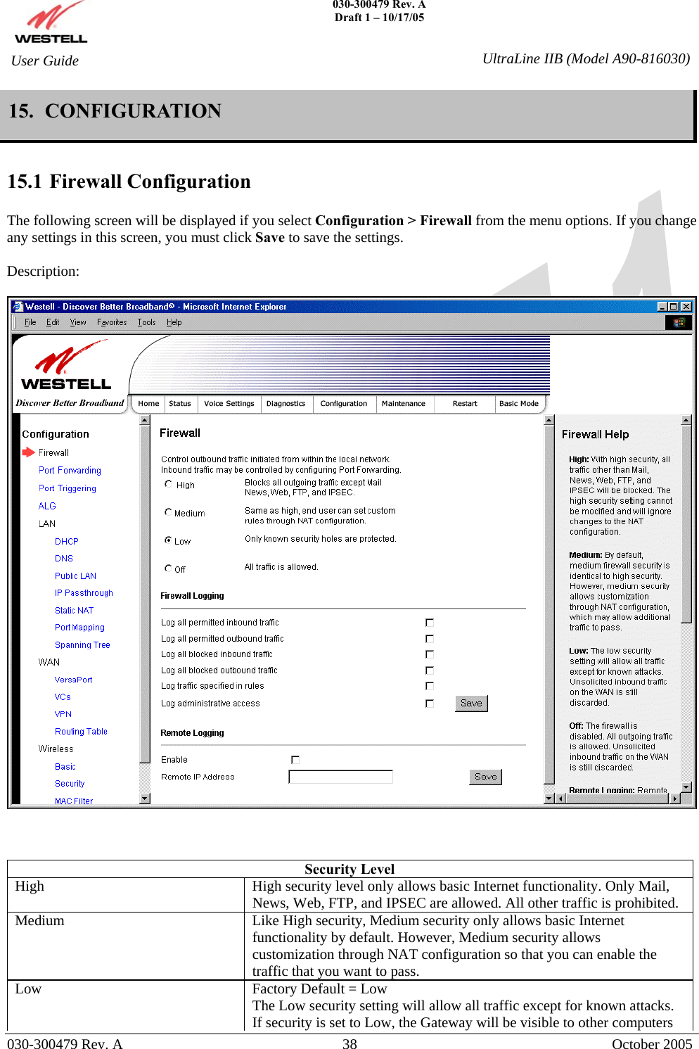
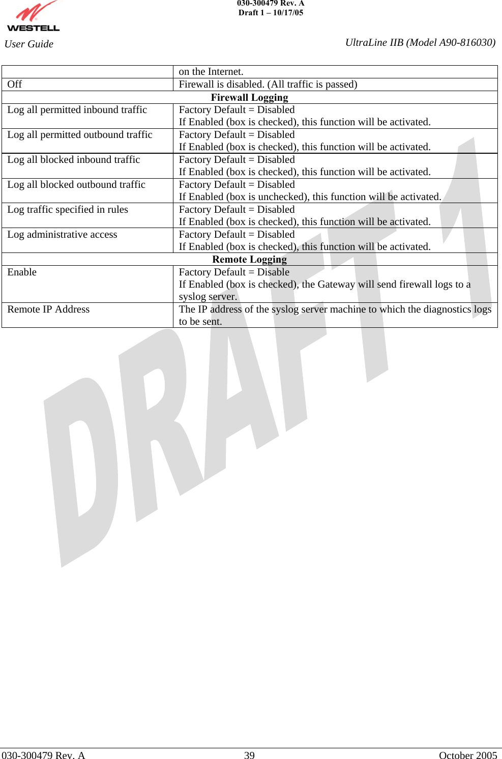
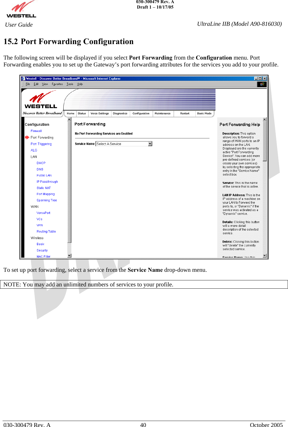
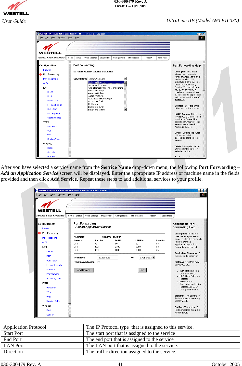
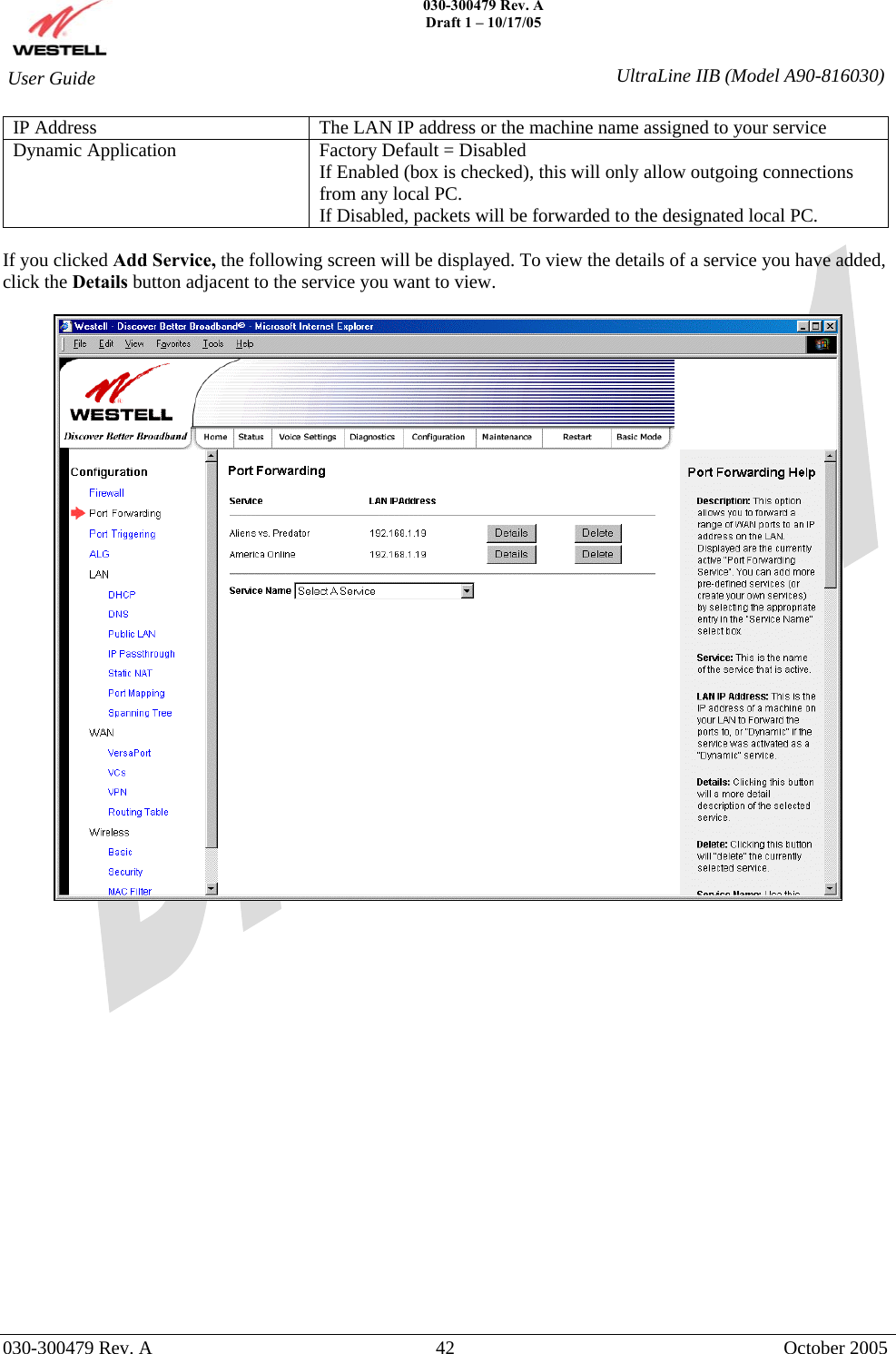
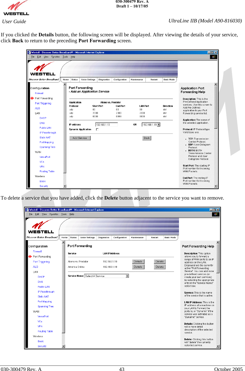
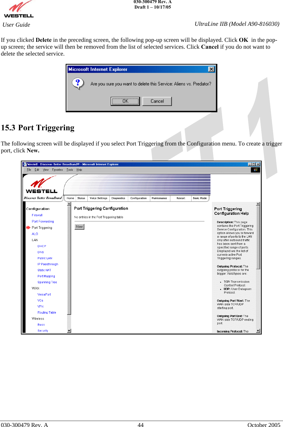
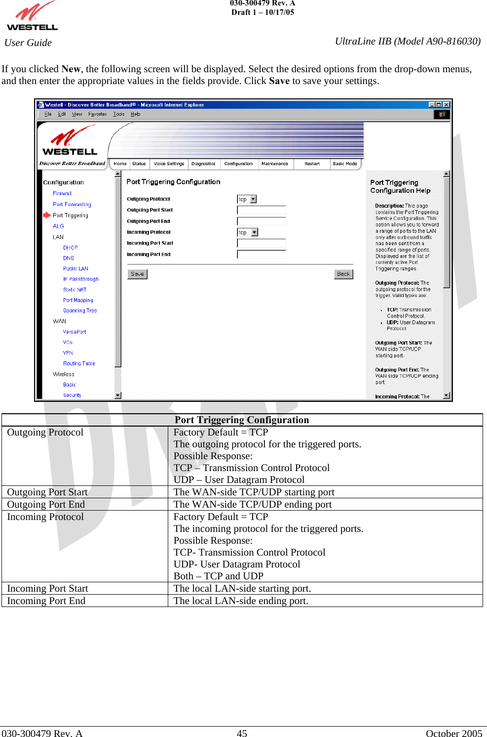
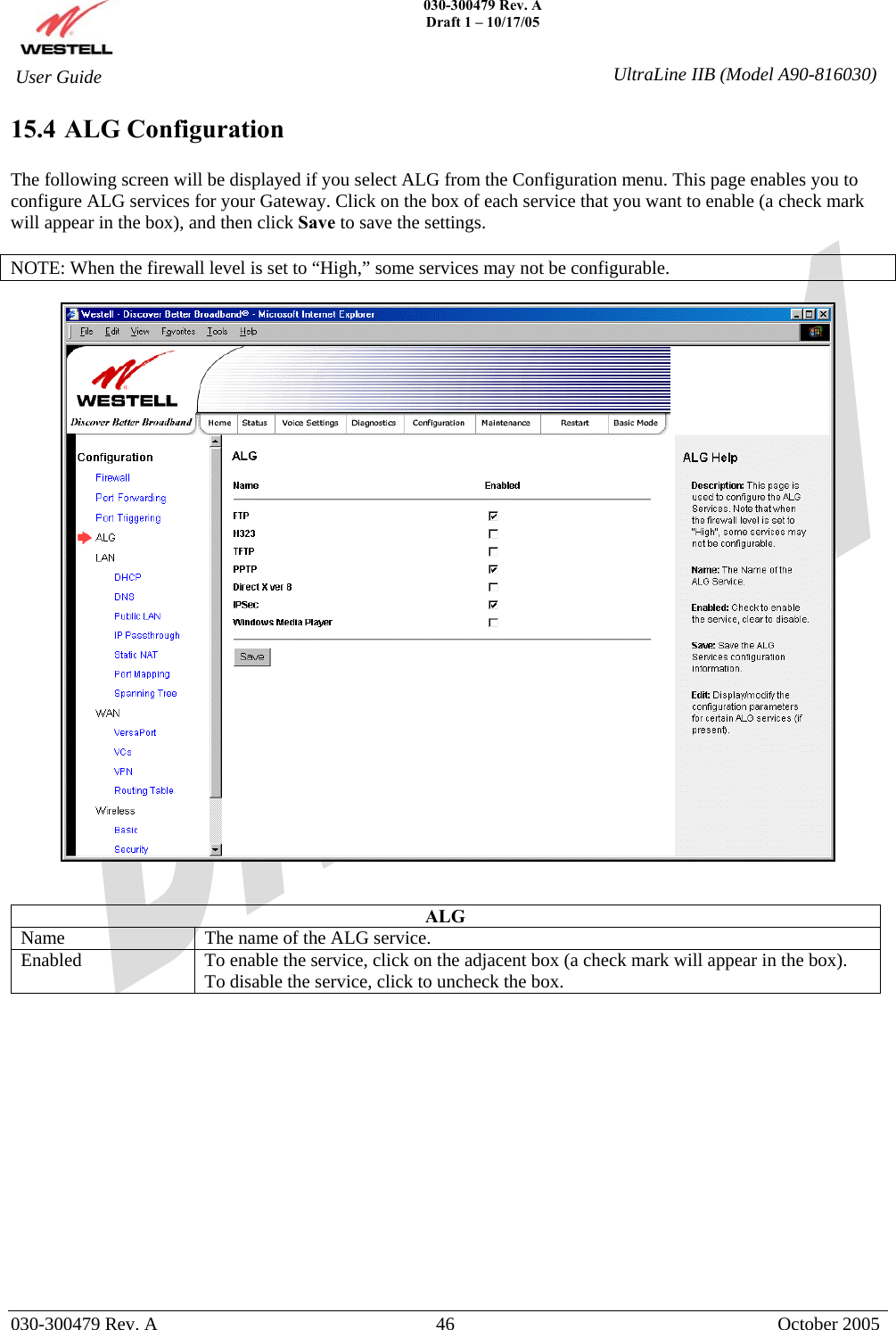
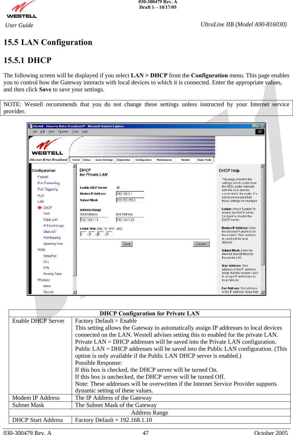
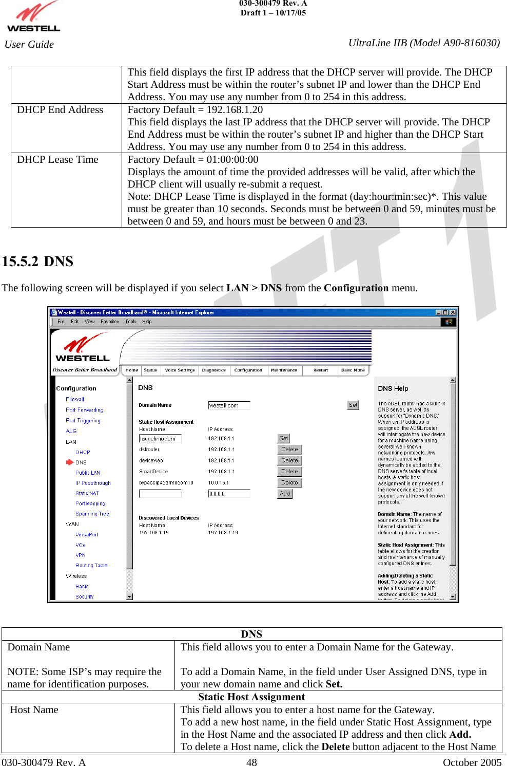
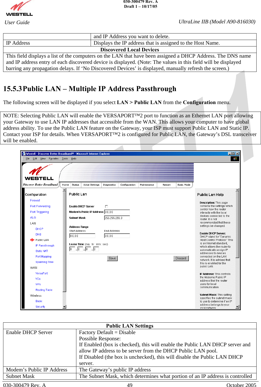
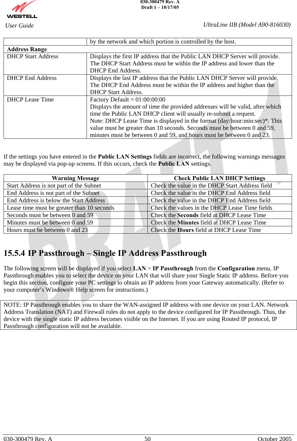
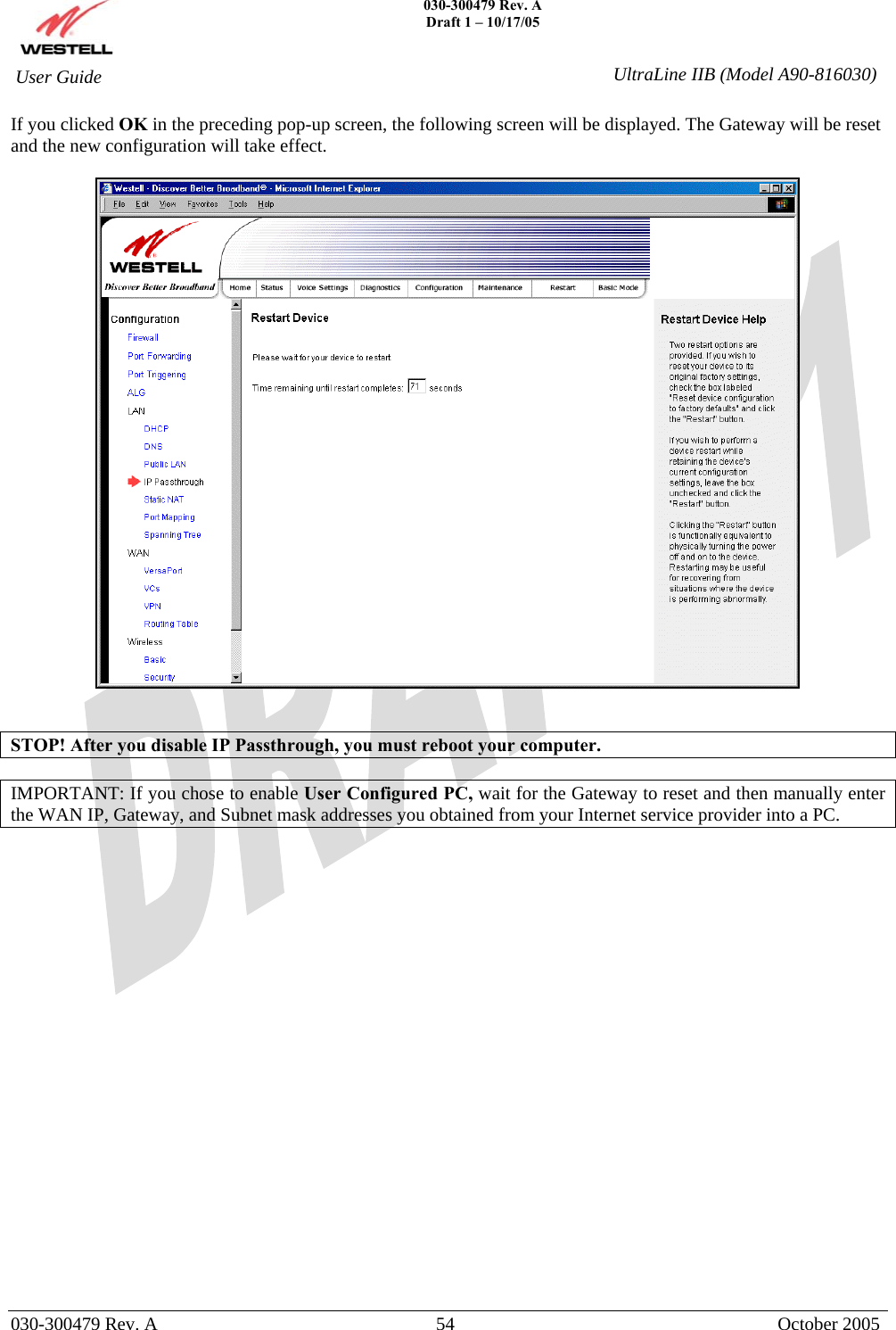
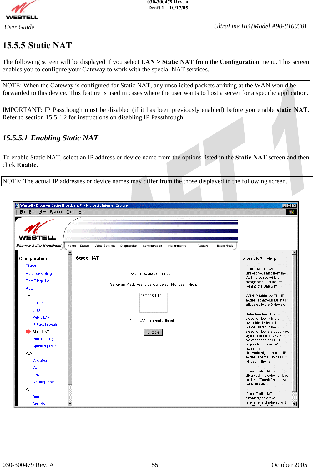
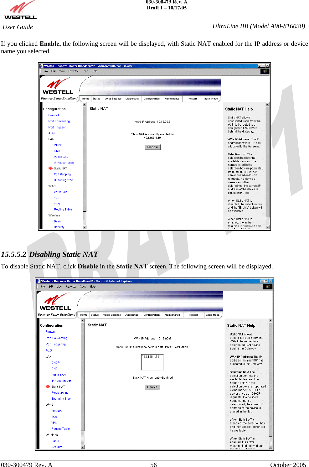
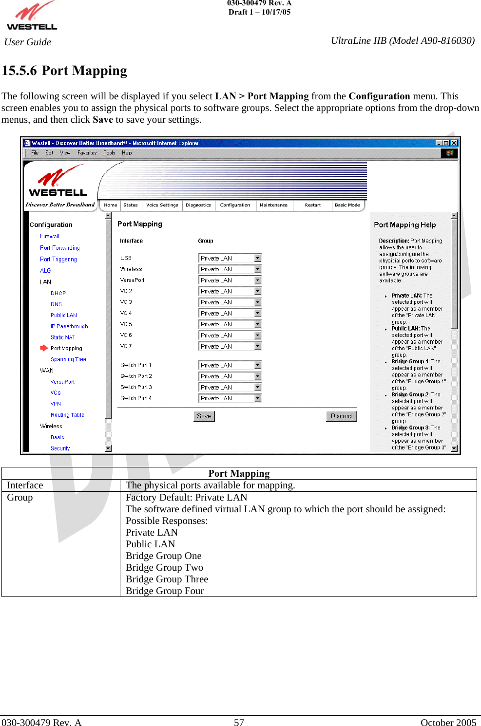
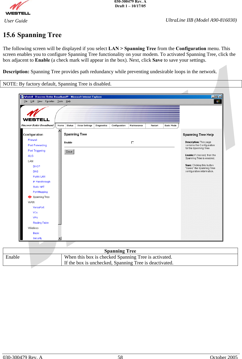
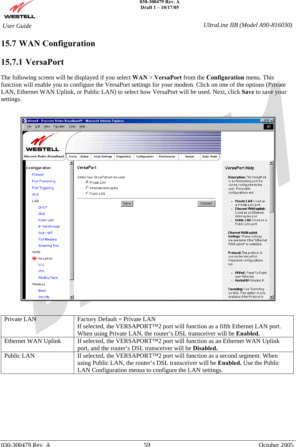
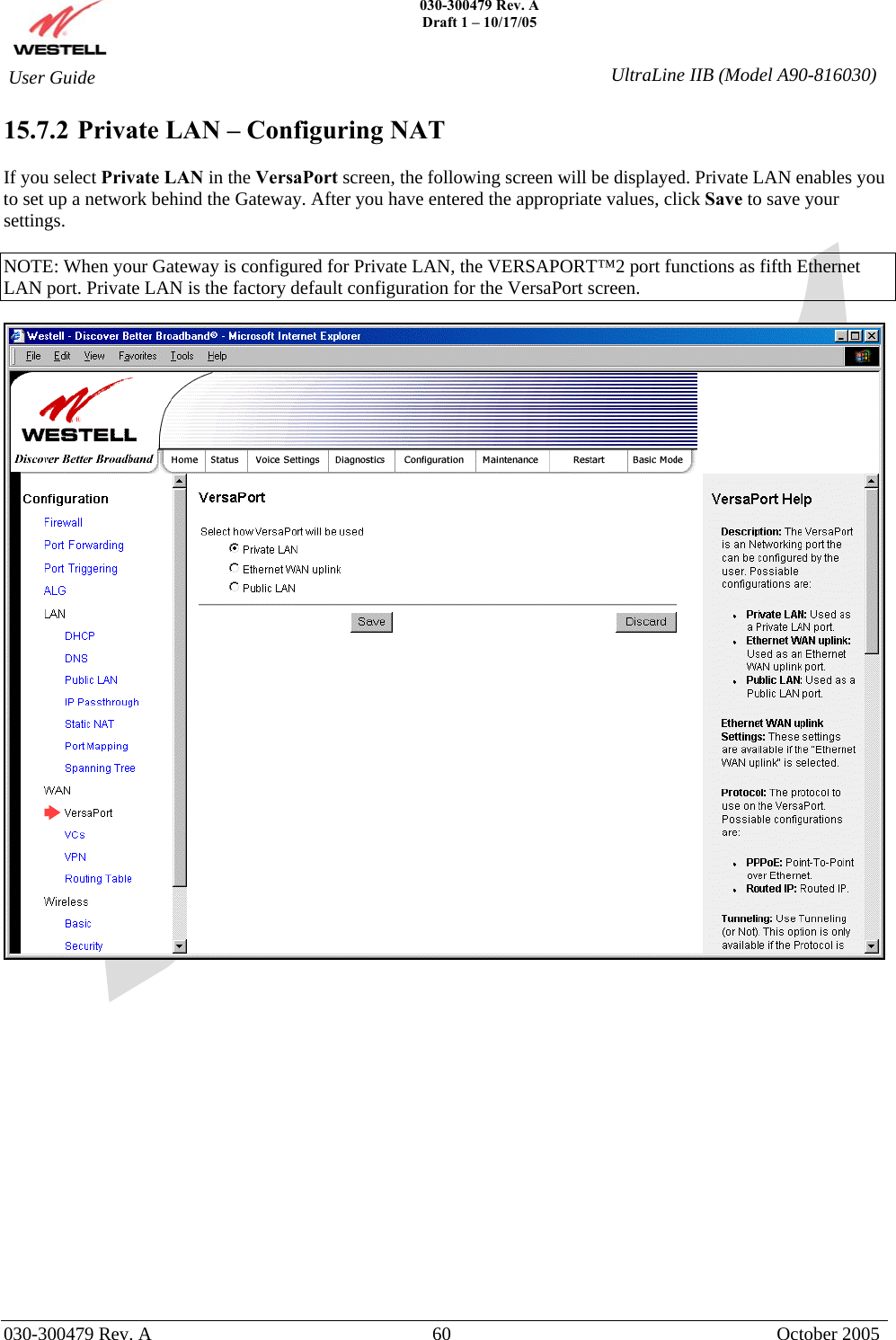
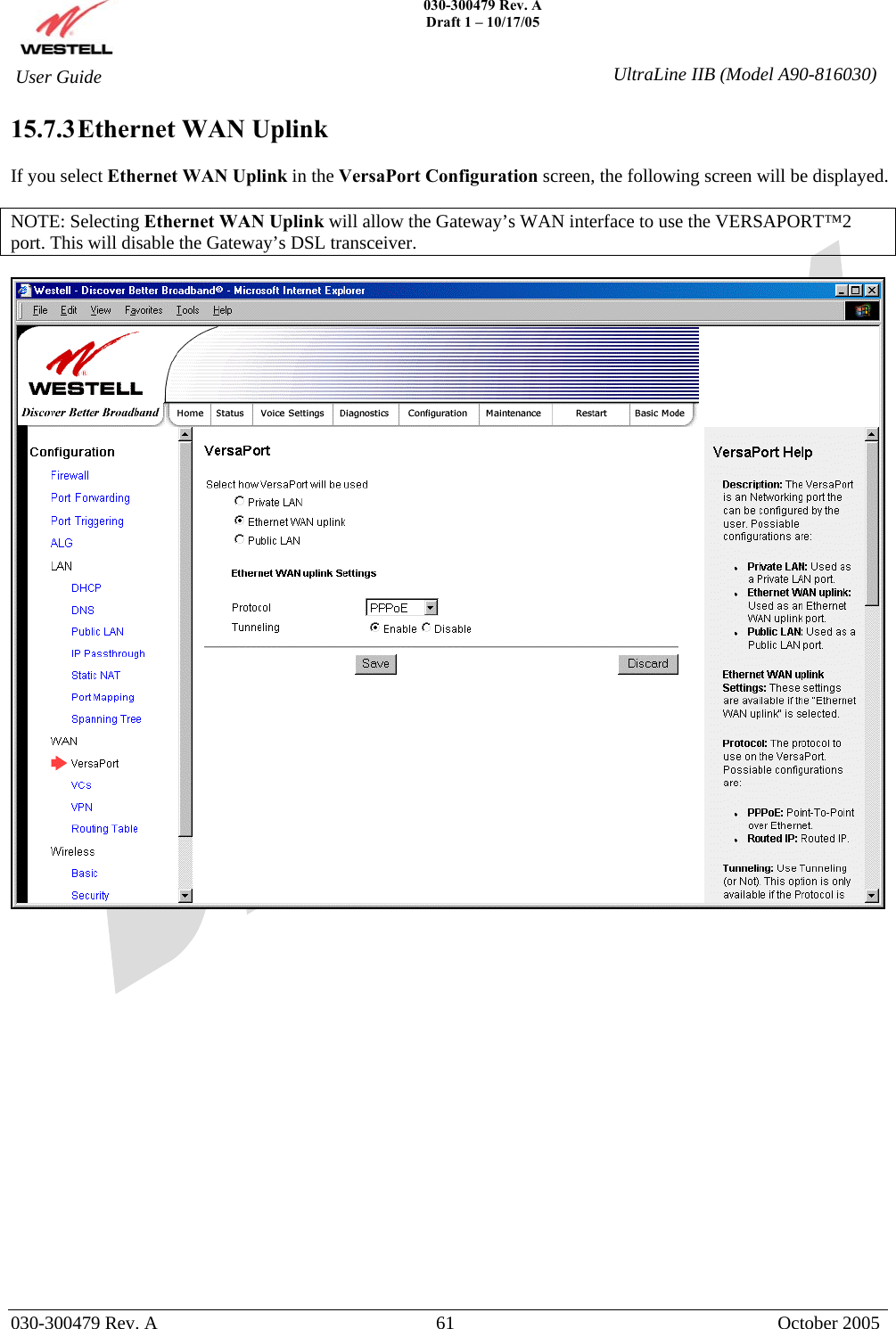
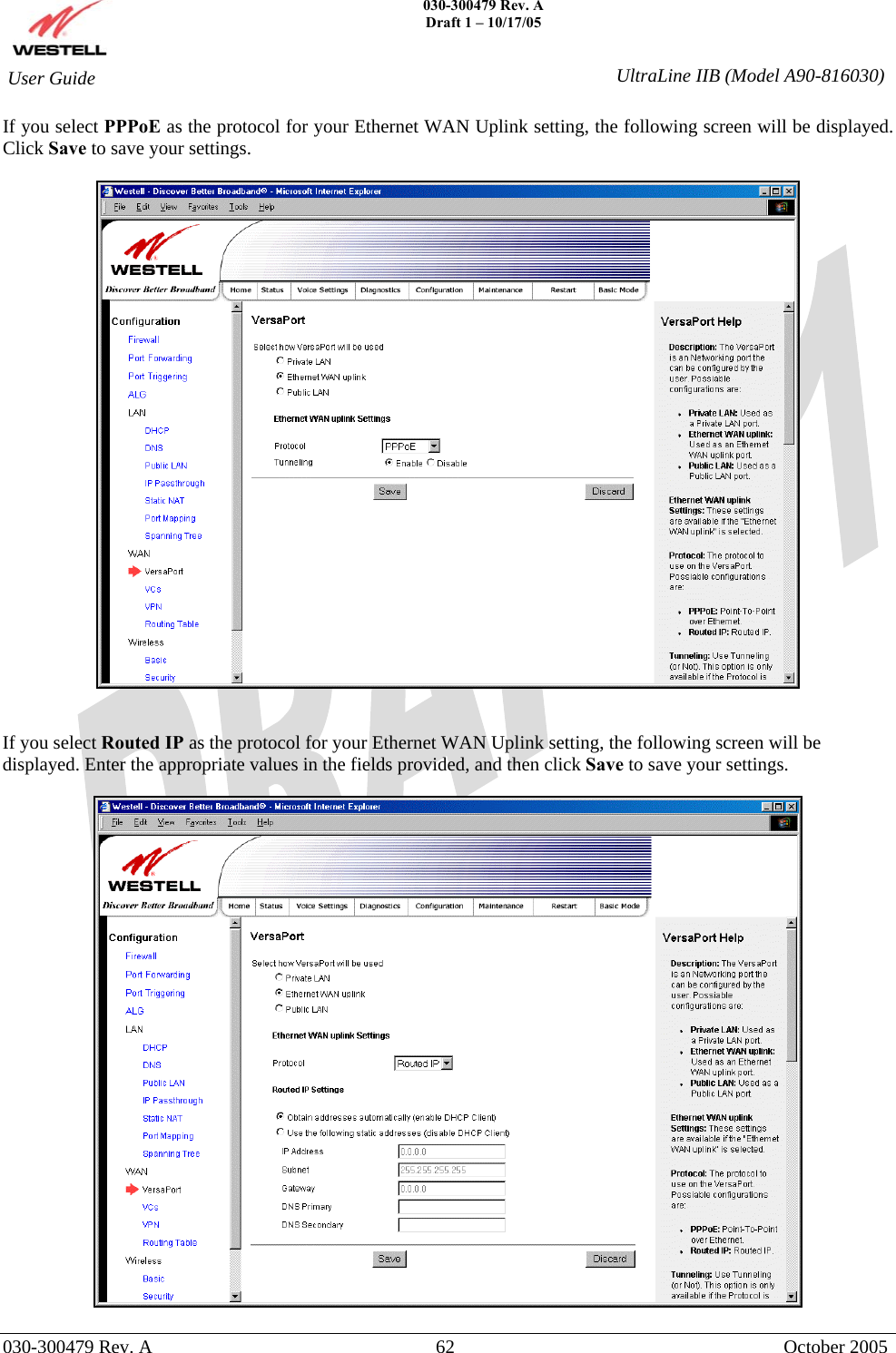
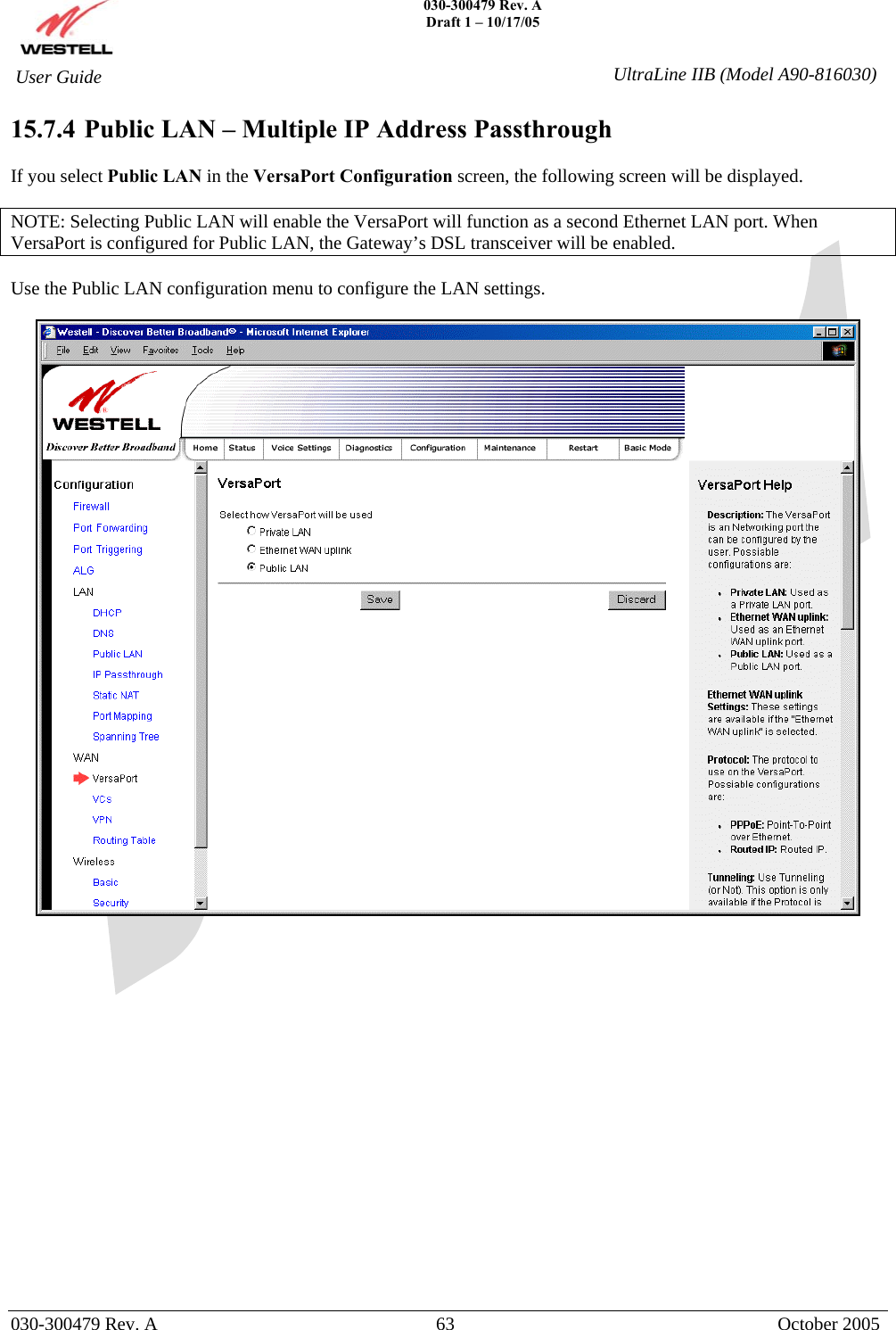
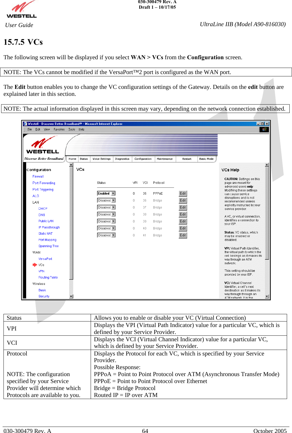
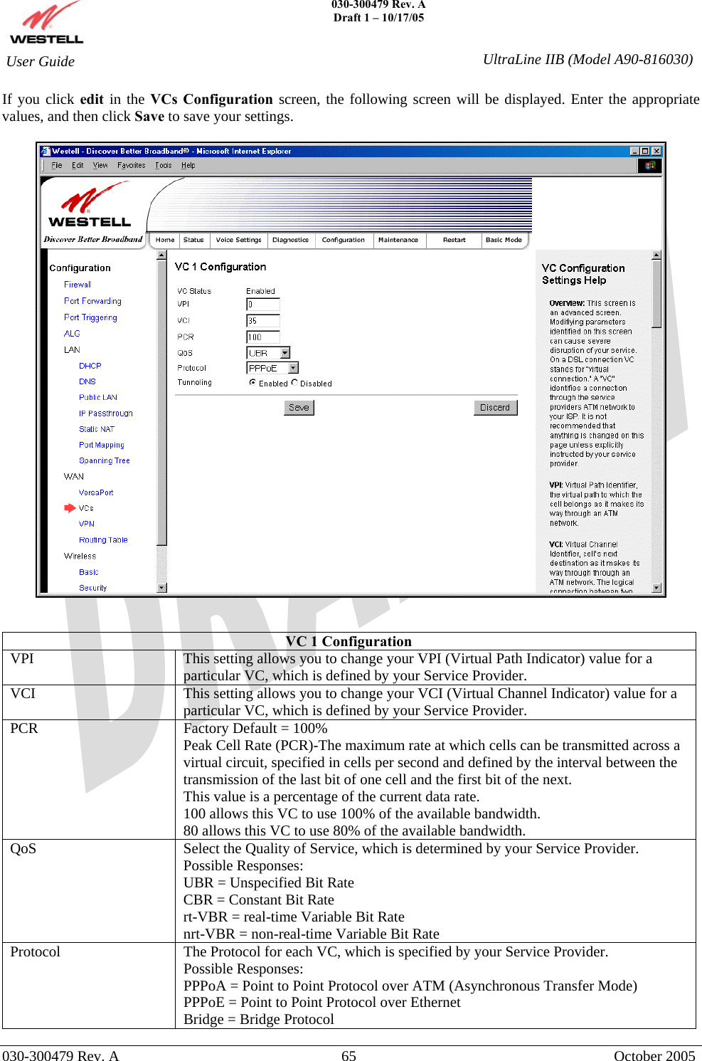
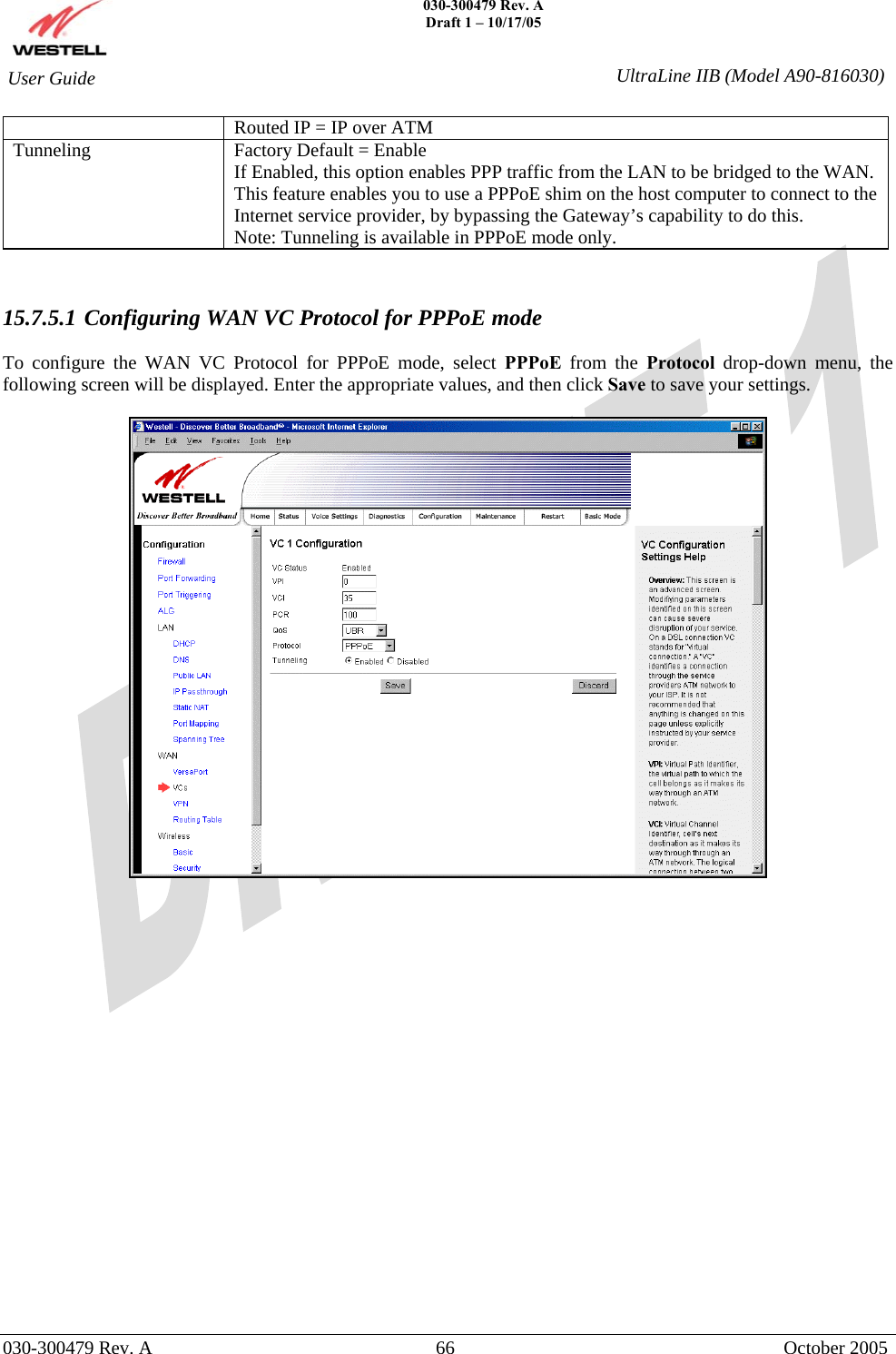
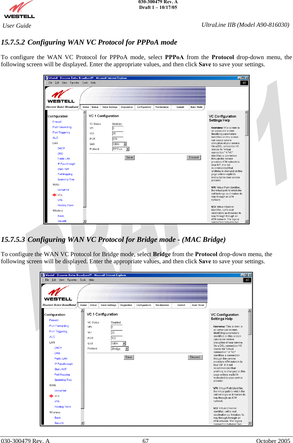
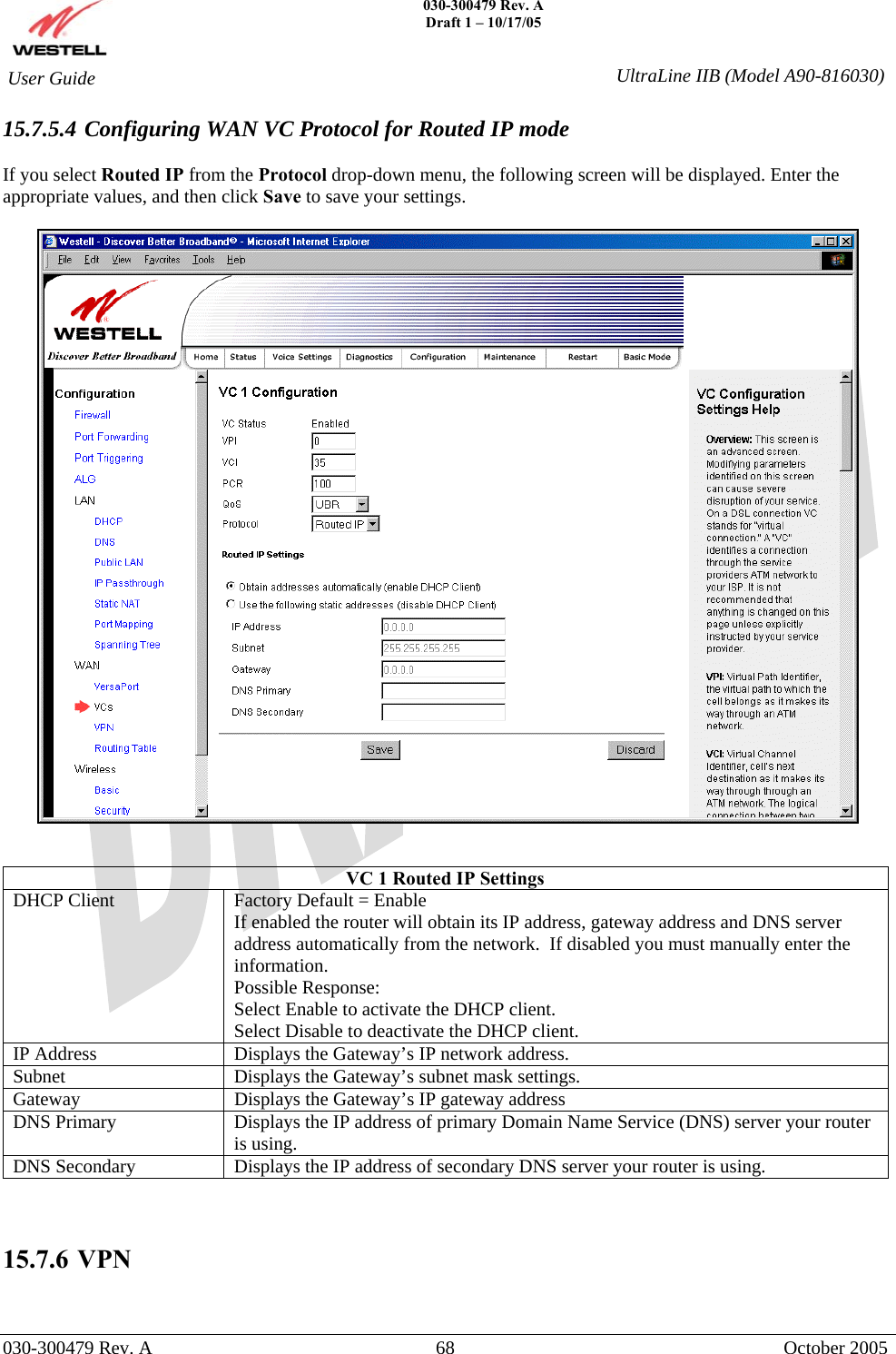
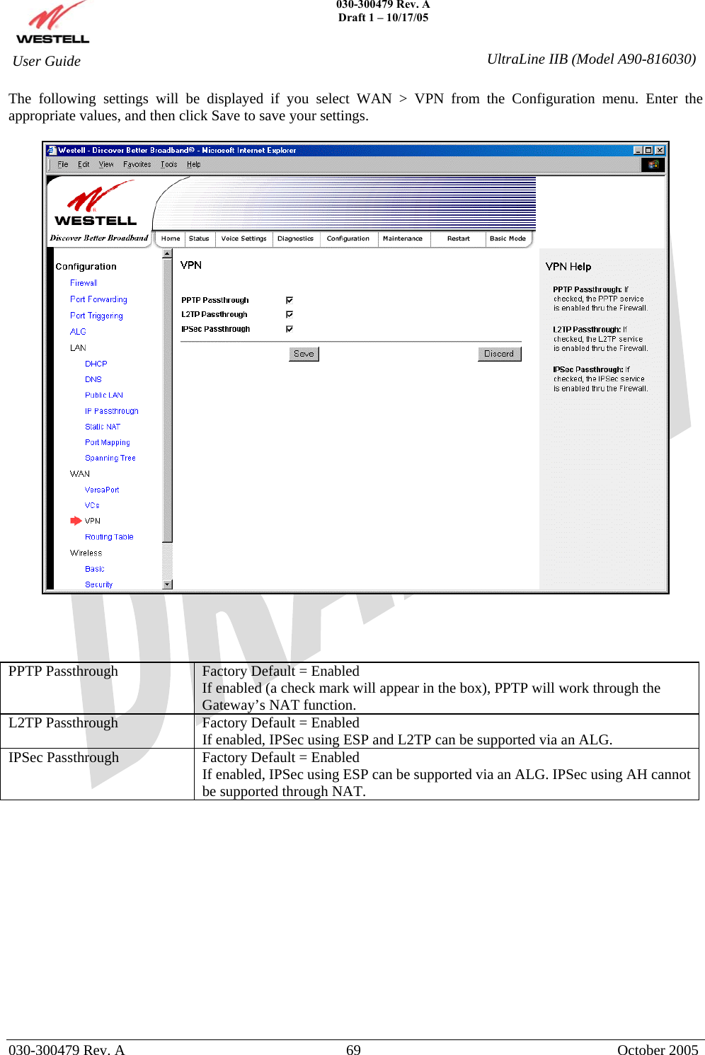
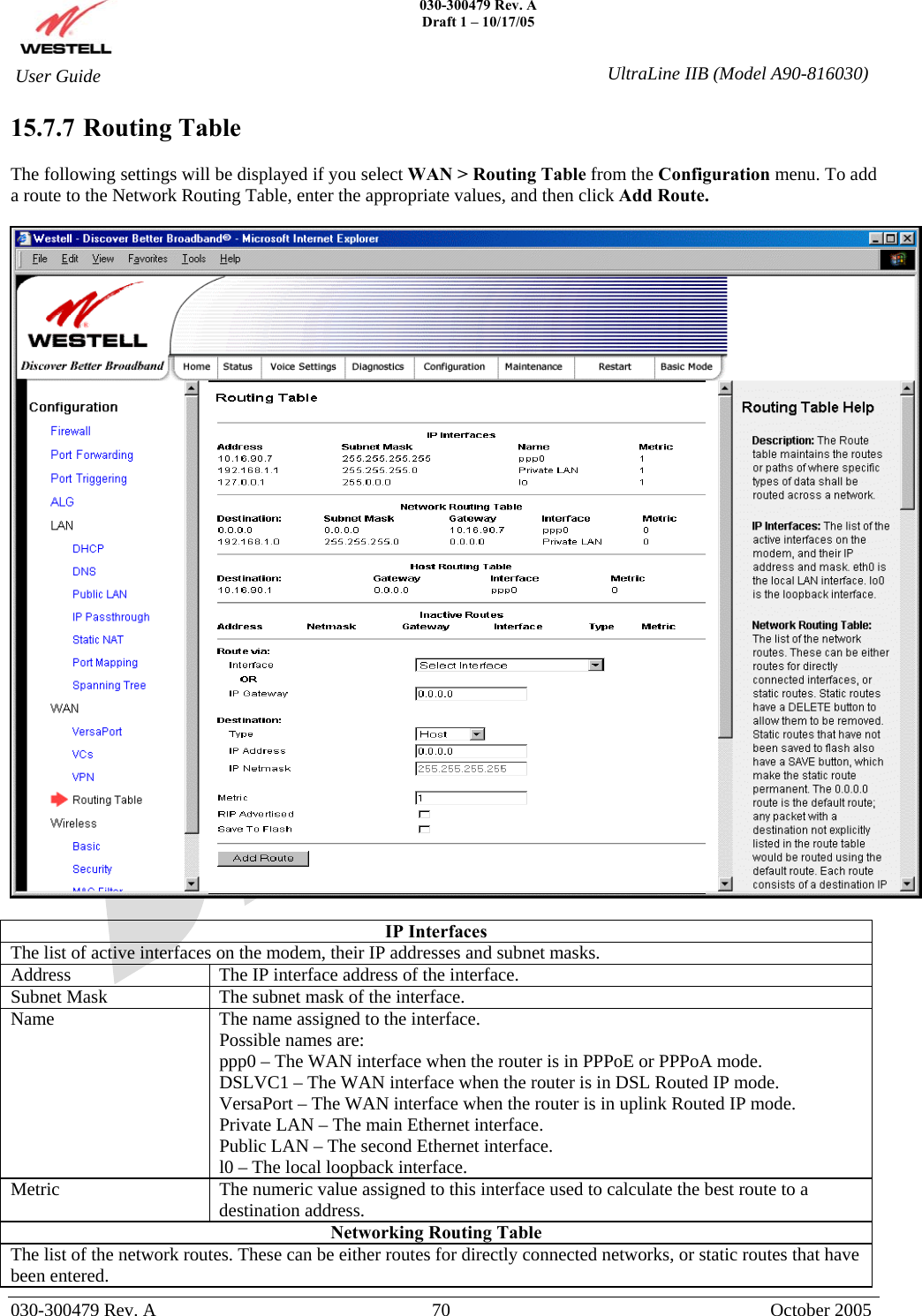
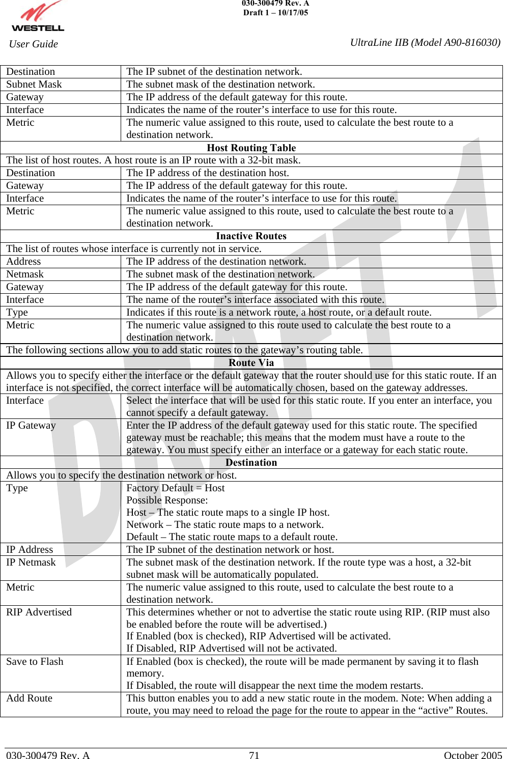
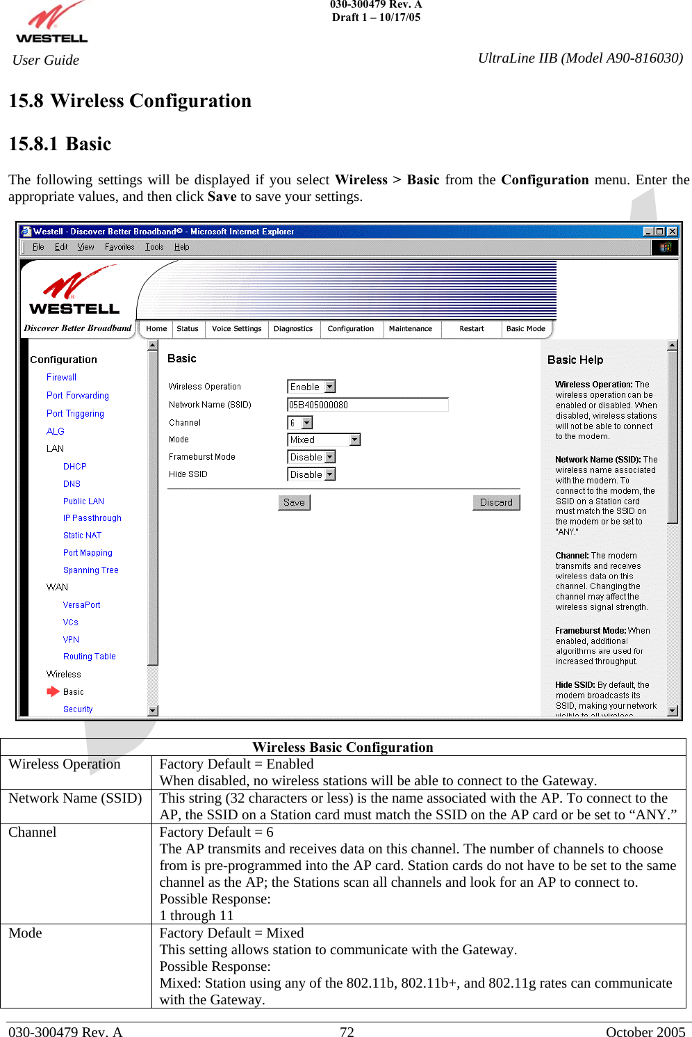
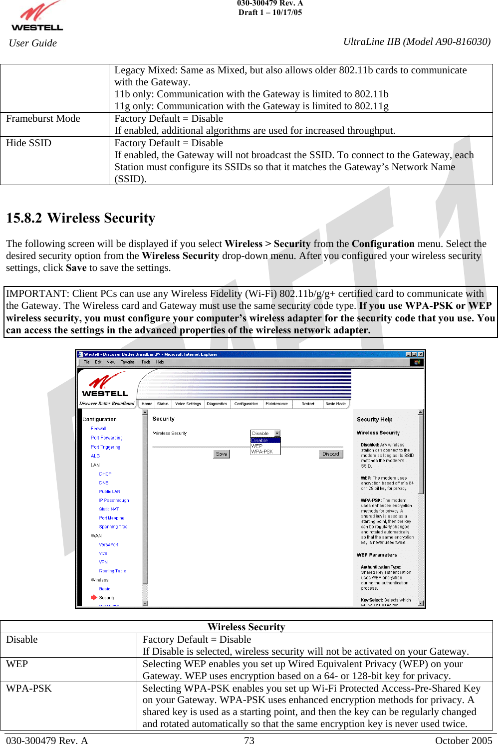
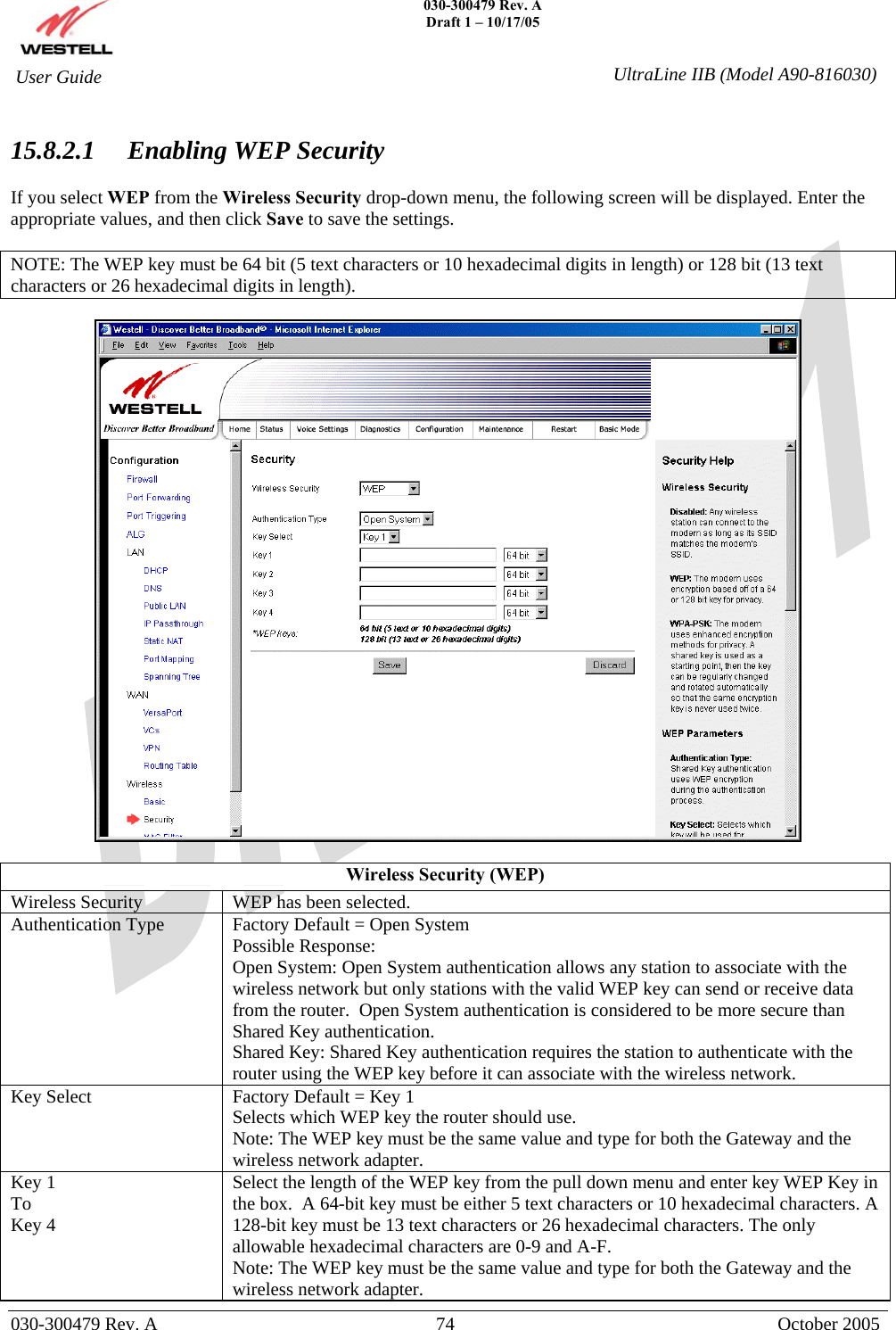
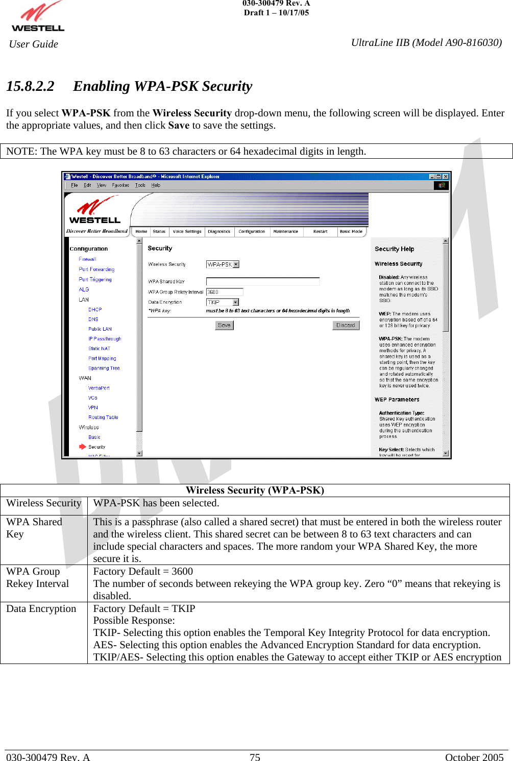
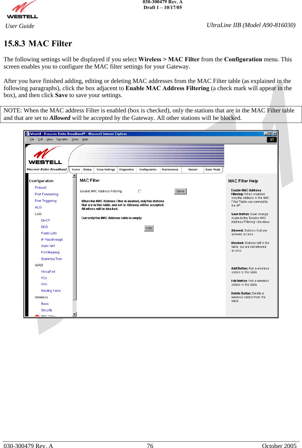
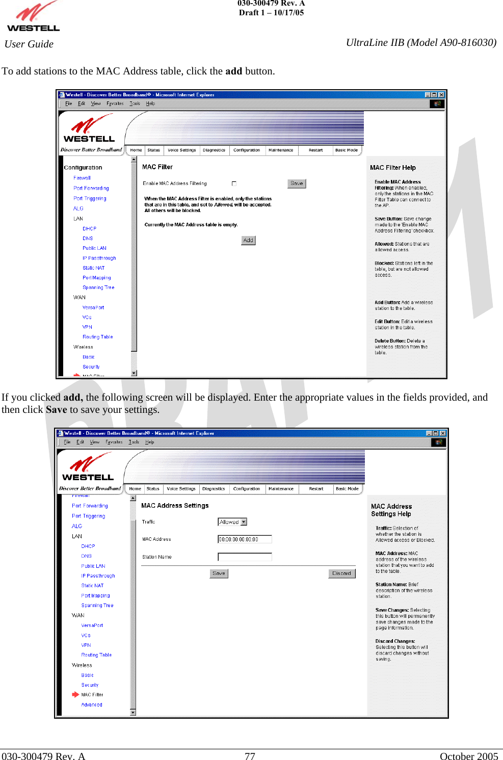
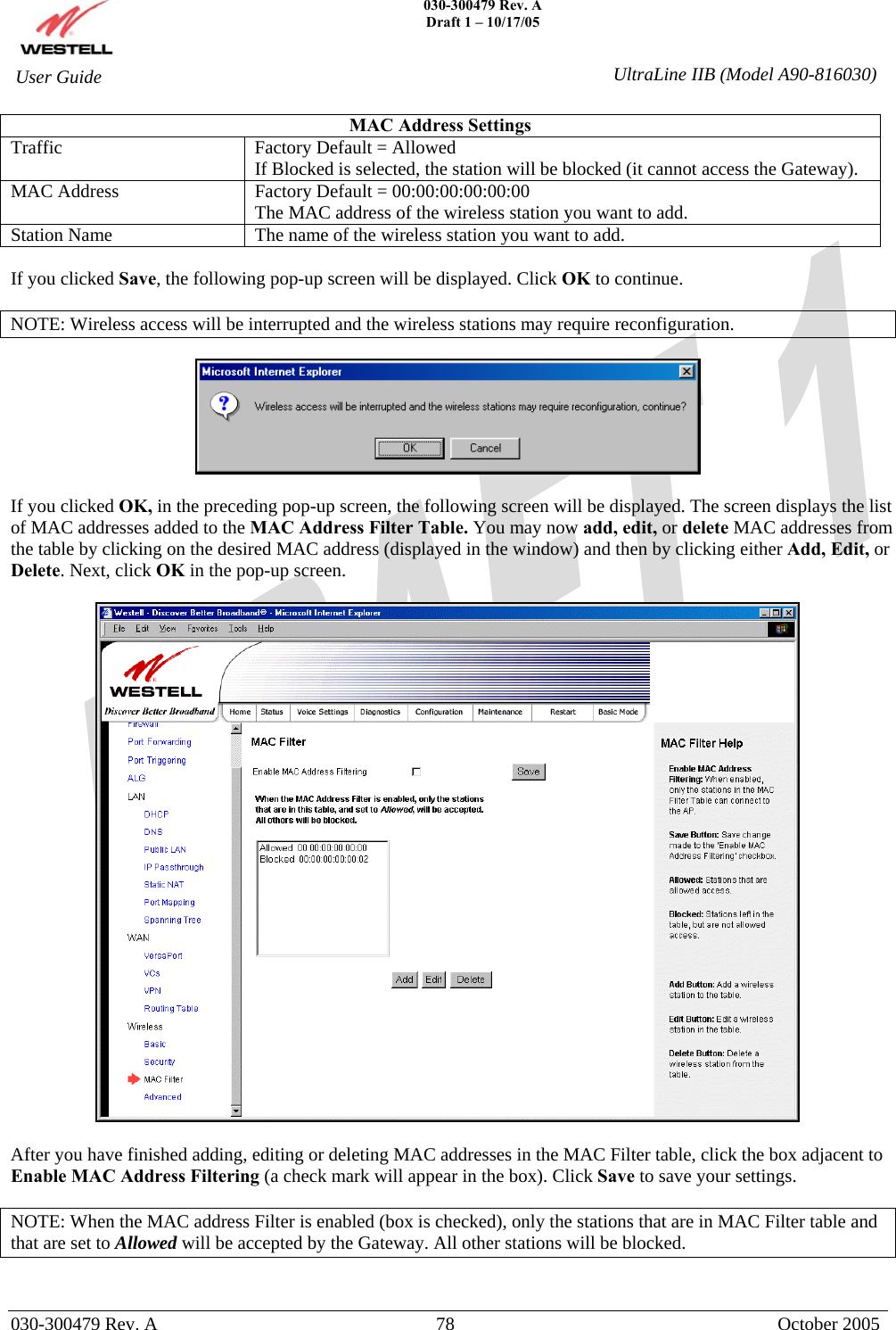
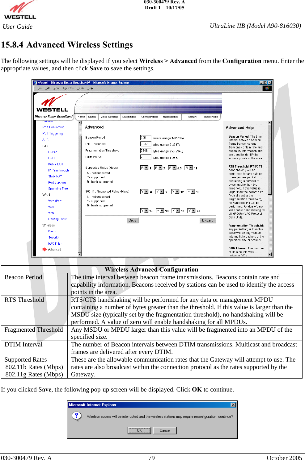
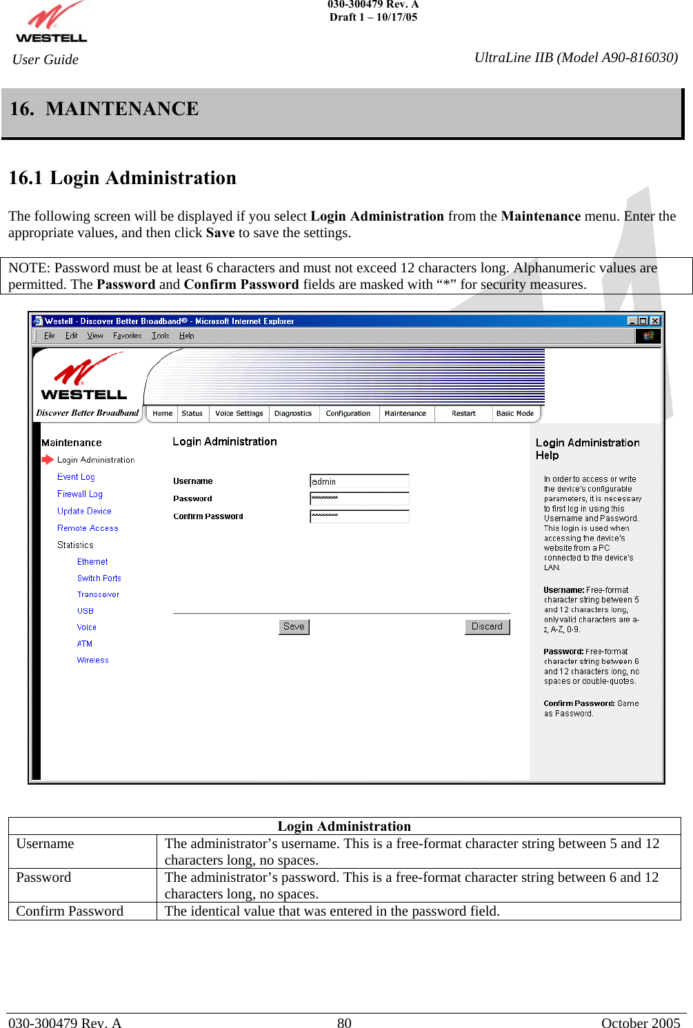
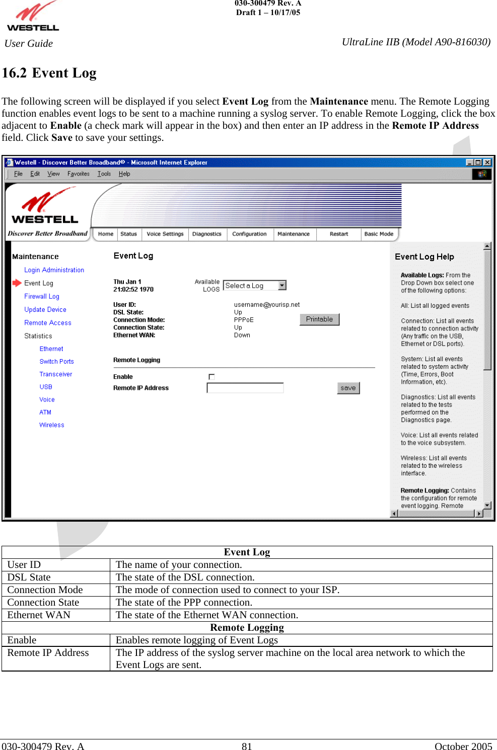
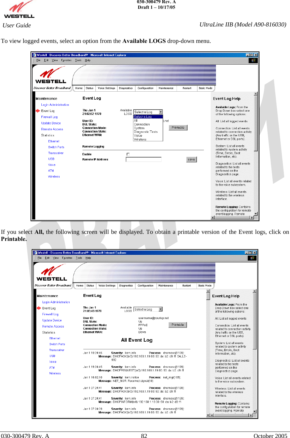
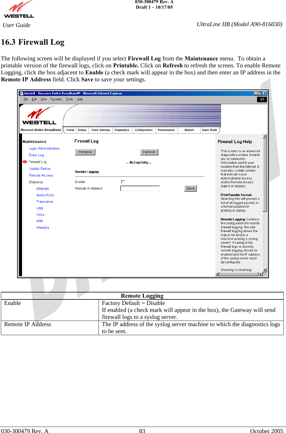
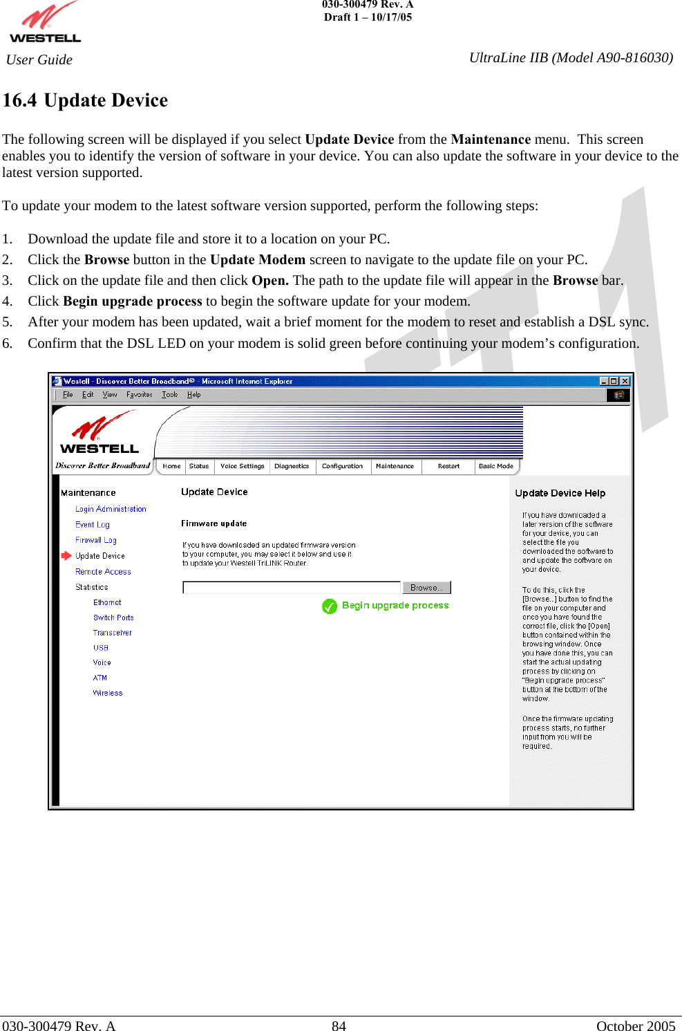
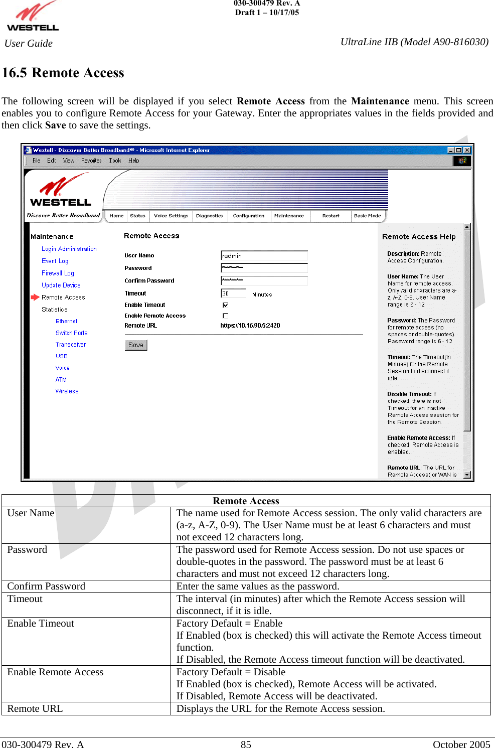
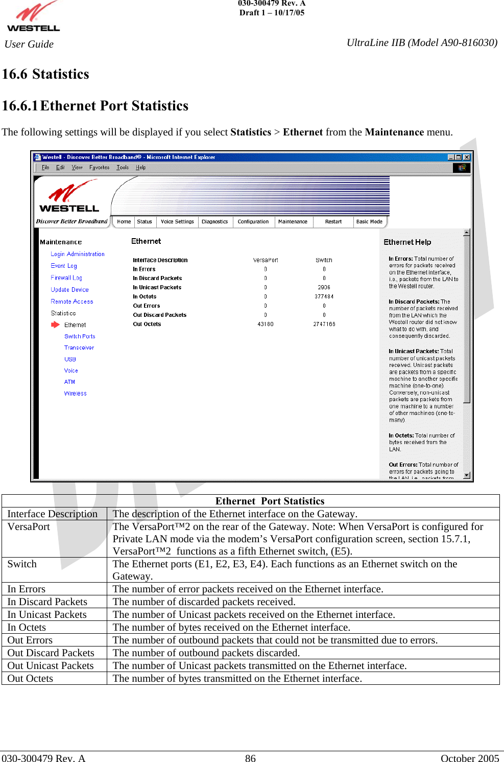
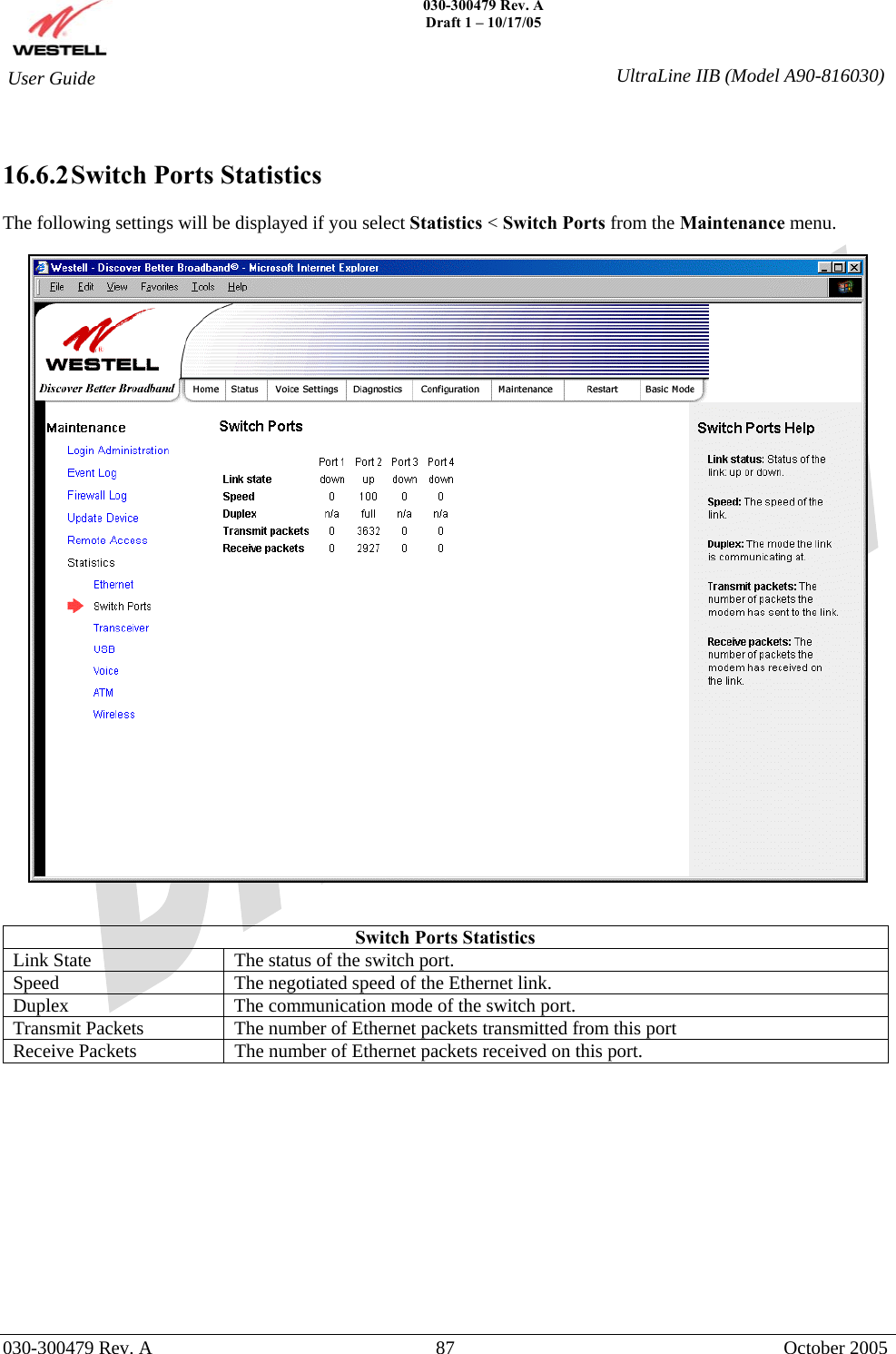
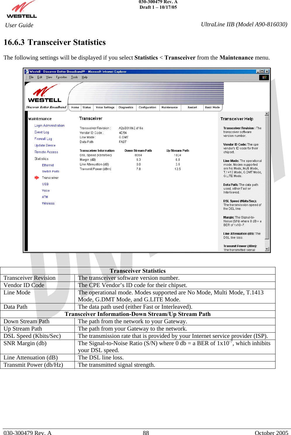
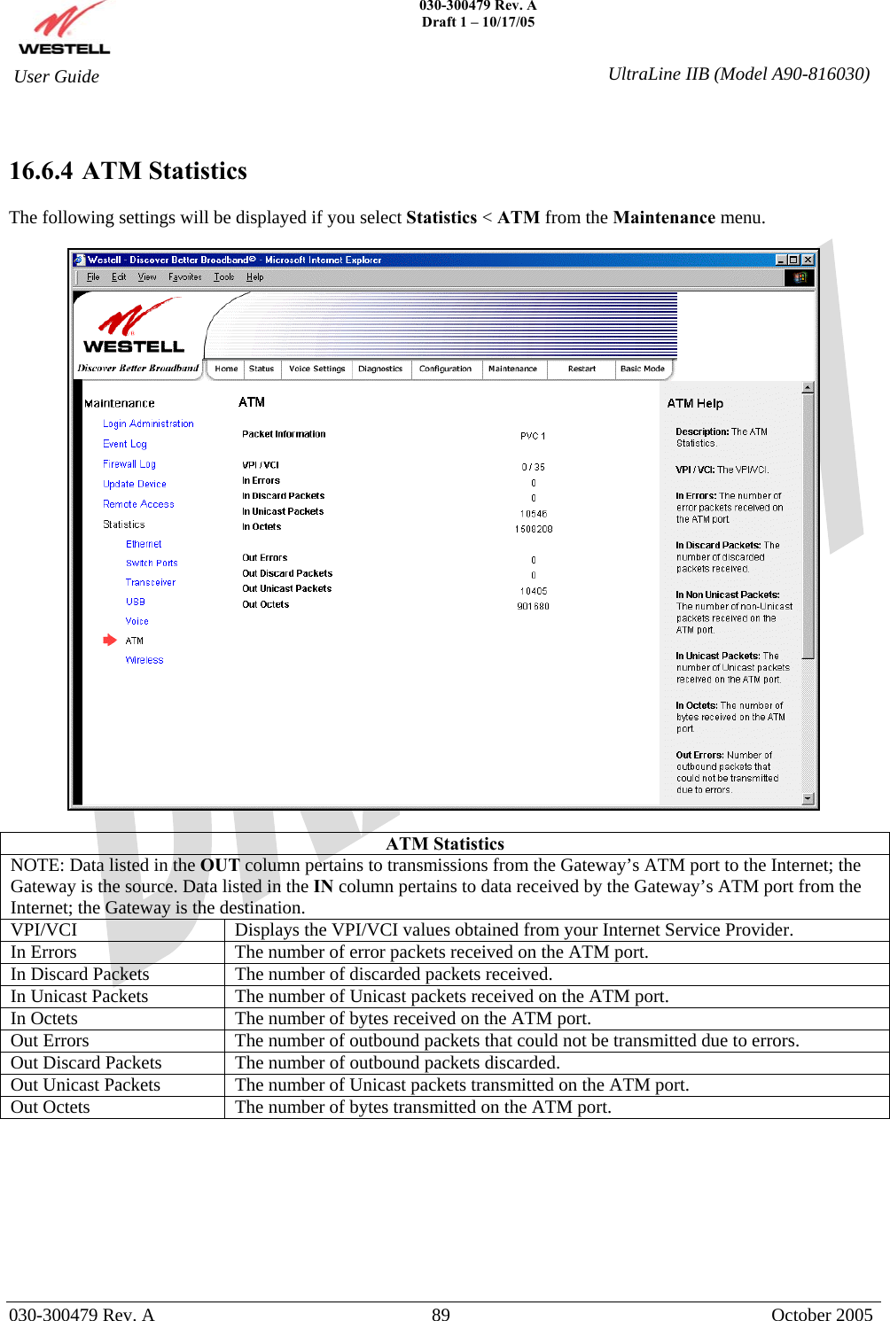
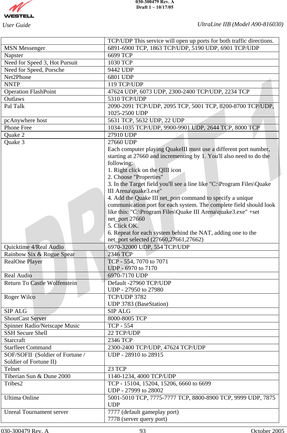
![030-300479 Rev. A Draft 1 – 10/17/05 030-300479 Rev. A 94 October 2005 User Guide UltraLine IIB (Model A90-816030)7779,7779+ are allocated dynamically for each helper UdpLink objects, including UdpServerUplin objects. Try starting with 7779-7781 and add ports if needed. 27900 server query, if master server uplink is enabled. Home master servers use other ports like 27500. Port 8080 is for UT Server Admin. In the [UWeb.WebServer] section of the server.ini file, set the ListenPort to 8080 and ServerName to the IP assigned to the router from your ISP. USENET News Service 143 TCP VNC, Virtual Network Computing 5500 TCP, 5800 TCP, 5900 TCP Westwood Online, C&C 4000 TCP/UDP, 1140-1234 TCP/UDP World Wide Web (HTTP) 80 TCP 443 TCP (SSL) 8008 or 8080 TCP (PROXY) Yahoo Messenger Chat 5000-5001 TCP Yahoo Messenger Phone 5055 UDP Xbox Live 88 TCP/UDP, 3074 TCP/UDP IPSec Encryption IPSec using AH can not be supported through NAT. IPSec using ESP and L2TP can be supported via an ALG L2TP IPSec using ESP and L2TP can be supported via an ALG. PPTP Works through NAT.](https://usermanual.wiki/Westell/A9081XXYY-07/User-Guide-595092-Page-94.png)